

Page 1
Water Softening
system
Safety Information . . . . . . . . . .2
Installation Instructions . .3–12
Step-by-step instructions . . .6–12
Operating Instructions
Breaking a salt bridge . . . . . . .14
Cleaning the nozzle and
venturi assembly . . . . . . . . . . .14
Features . . . . . . . . . . . . . . . . . .15
Service . . . . . . . . . . . . .13, 16–18
Water softener system . . . .13–18
Care and Cleaning . . . . . . . .19
Troubleshooting Tips . . . .20–22
Consumer Support
Consumer Support . .Back Cover
Parts list/catalog . . . . . . . .24–27
Warranty (U.S.) . . . . . . . . . . . .28
Warranty (Canada) . . . . . . . . .29
Modelos GXSF35E, GXSF39E
Manual del Propietario e
Instrucciones de Instalación
La sección en español empieza en la página 31
Sistema Suavizante
de Agua
www.GEAppliances.com
7247174 215C1173P010 49-50151 02-05 JR
Write the model and serial numbers here:
Model # ____________________________
Serial # ____________________________
To find these numbers, lift the cover and
look on the rim below the control panel.
Models GXSF35E, GXSF39E
Owner’s Manual &
Installation Instructions
Water Softening
System
System tested and certified by NSF International against NSF/ANSI Standard 44 for the
chemical reduction claims specified on the performance data sheet.
Sistema probado y certificado por NSF International contra norma 44 de NSF/ANSI para
las afirmaciones de reducción de los productos químicos especificadas en la hoja de datos
de funcionamiento.
Page 2
IMPORTANT SAFETY INFORMATION.
READ ALL INSTRUCTIONS BEFORE USING.
SAFETY PRECAUTIONS
■ Check and comply with your state and local
codes. You must follow these guidelines.
■ Use care when handling the water softening
system. Do not turn upside down, drop, drag
or set on sharp protrusions.
■ Water softening systems using sodium chloride
(salt) for recharge add sodium to the water.
Persons on sodium restricted diets should consider
the added sodium as part of their overall intake.
Potassium chloride can be used as an alternative
to sodium chloride in your softener.
■
The water softening system works on 24 volt-60 Hz
electrical power only. Be sure to use only the
included transformer.
■ Transformer must be plugged into an indoor
120 volt, grounded outlet only.
■ Use clean water softening salts only, at least
99.5% pure. NUGGET, PELLET or coarse
SOLAR salts are recommended. Do not use rock,
block, granulated or ice cream making salts.
They contain dirt and sediments, or mush and
cake, and will create maintenance problems.
■ Keep the salt hole cover in place on the softener
unless servicing the unit or refilling with salt.
WARNING: Do not use with water that is
microbiologically unsafe or of unknown quality
without adequate disinfection before or after
the system.
READ AND FOLLOW THIS SAFETY INFORMATION CAREFULLY.
SAVE THESE INSTRUCTIONS
PROPER INSTALLATION
■ Install or store where it will not be exposed to
temperatures below freezing or exposed to any
type of weather. Water freezing in the system will
break it. Do not attempt to treat water over 100°F.
■ Do not install in direct sunlight. Excessive sun or
heat may cause distortion or other damage to
non-metallic parts.
■ Properly ground to conform with all governing
codes and ordinances.
■ Use only lead-free solder and flux for all sweat-
solder connections, as required by state and
federal codes.
■
The water softening system requires a minimum
water flow of three gallons per minute at the inlet.
Maximum allowable inlet water pressure is 125 psi.
If daytime pressure is over 80 psi, nighttime
pressure may exceed the maximum. Use a pressure
reducing valve to reduce the flow if necessary.
■
Softener resins may degrade in the presence
of chlorine above 1 ppm. If you have chlorine
in excess of this amount, you may experience
reduced life of the resin. In these conditions,
you may wish to consider purchasing a GE
point-of-entry household filtration system with
a chlorine reducing filter.
WARNING: Discard all unused parts
and packaging material after installation.
Small parts remaining after the installation
could be a choke hazard.
This water softening system must be properly installed and located in accordance with the Installation
Instructions before it is used.
2
For your safety, the information in this manual must be followed to minimize the risk of electric shock,
property damage or personal injury.
WARNING!
Page 3
3
CAUTION: Certain plumbing skills are needed for installation. If you are unsure about
any part of the installation of this product, consult a professional plumber.
Installation instructions.
GEAppliances.com
Unpacking and Inspection
Be sure to check the entire softener for any
shipping damage or parts loss. Also note
damage to the shipping cartons. Contact the
transportation company for all damage and
loss claims. The manufacturer is not
responsible for damages in transit.
Small parts needed to install the softener are
packaged either in a bag or on a cardboard
sheet. To avoid loss of the small parts, keep
them packaged until you are ready to use them.
Be sure not to discard components hidden in
packaging.
■ Before you begin installation, read these
Installation Instructions completely. Then,
obtain all the materials and tools you will
need to make the installation. Failure to
properly install the softener voids the
warranty.
■ Check local codes. The installation must
conform to them.
■ In the Commonwealth of Massachusetts,
Plumbing Code 248 CMR shall be adhered to.
Consult with your licensed plumber.
■ Use only lead-free solder and flux for all
sweat-solder connections, as required by
state and federal codes.
■ Connect the softener to the main water
supply pipe before or ahead of the water
heater. DO NOT RUN HOT WATER THROUGH
THE SOFTENER. Temperature of water
passing through the softener must be
less than 120°F.
■ Use care when handling the softener.
Do not turn upside down, drop, drag
or set on sharp protrusions.
■ Maximum allowable inlet water pressure is
125 psi. If daytime pressure is over 80 psi,
nighttime pressure may exceed the
maximum. Use a pressure reducing valve
if necessary. (Adding a pressure reducing
valve may reduce the flow.)
■ The softener works on 24 volt-60 Hz
electrical power only. Be sure to use the
included transformer. Be sure the electric
outlet and transformer are in an inside
location to protect from moisture.
■ See Where to Install the Softener section for
more details.
WARNING:Do not use with water
that is microbiologically unsafe or of
unknown quality without adequate
disinfection before or after the system.
The water should be tested periodically
to verify that the system is performing
satisfactorily.
■ Small parts remaining after the installation
could be a choke hazard. Discard safely.
Important Installation Recommendations
Read entire manual. Failure to follow all guidelines and rules could cause personal injury or
property damage.
Page 4
4
Installation instructions.
Plan How You Will Install the Softener
You must first decide how to run in and out
pipes to the softener. Look at the house
main water pipe at the point where you will
connect the softener. Is the pipe soldered
copper, glued plastic or threaded galvanized?
What is the pipe size?
WARNING: Use only lead-free
solder and flux to prevent lead poisoning.
See Typical Installation Illustration, Fig. 1. Use
this as a guide when planning your particular
installation. Be sure to direct the incoming hard
water supply to the softener valve inlet fitting.
The valve is marked IN and OUT. See illustration
on page 5 to help you prepare.
Where to Install the Softener
■ Place the softener as close as possible to a
sewer drain, or other acceptable drain point
or standpipe.
■ It is recommended to keep outside faucets
on hard water to save soft water and salt.
■
Do not install the softener in a place where it
could freeze. Freeze damage is not covered by
the warranty.
■ Do not install the softener where it would
block access to the water heater or access to
the main water shutoff.
■ Put the softener in a place where water
damage is least likely to occur if a leak
develops. The manufacturer will not repair
or pay for water damage.
■ A 120 volt electric outlet is needed to plug
in the included transformer. The softener
has a 10 foot power cable. If the outlet is
remote (up to 100 feet), use 18 gauge wire
to connect. Be sure the electric outlet and
transformer are in an inside location, to protect
from wet weather. Be sure the outlet is
unswitched to prevent accidental shutoff.
■ If installing in an outside location, you must
take the steps necessary to assure the softener,
installation plumbing, wiring, etc., are as
well protected from the elements (sunlight,
rain, wind, heat, cold), contamination,
vandalism, etc., as when installed indoors.
Outdoor installation is not recommended and
voids the warranty.
■ Keep the softener out of direct sunlight.
The sun’s heat may distort non-metallic
parts and may damage the electronics.
■ In and out fittings included with the softener
are 3/4″ (nominal) copper sweat tubes.
You should maintain the same, or larger,
pipe size as the water supply pipe, up to the
softener inlet and outlet.
■ Use the included bypass valve to install the
softener. The bypass valve allows you to turn
off water to the softener for servicing, but
still have water in the house pipes. The in
and out fittings referred to above connect to
the bypass valve with the included nuts and
washers.
■ Use copper, brass or galvanized pipe and
fittings. Some codes may also allow CPVC
plastic pipes.
■ If additional drain hose is needed for valve
and salt tank drains, it can be ordered from
GE Parts at 800.626.2002.
■ If a rigid valve drain is needed to comply
with plumbing codes, you can buy the parts
needed to connect a 1/2″ copper tubing or
plastic pipe drain.
■ Clean nugget or pellet water softener salt is
needed to fill the brine tank, see Step 8 in
the Step-by-Step Installation Instructions.
Tools and Materials Required for Installation
Page 5
5
GEAppliances.com
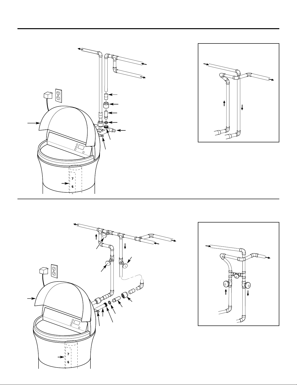
Typical Installation Illustration
Soft water
Hard water to
outside faucets
MAIN WATER PIPE
Hard water
NOTE: See Drain Hose Connections section.
24V transformer
120-volt outlet
Bypass valve
Hard water to
outside faucets
Inlet valve
Outlet valve
3-Valve Bypass System
For soft water service:
• Open the inlet and
outlet valves
• Close the bypass valve
For bypass hard water:
• Close the inlet and
outlet valves
• Open the bypass valve
Salt hole
cover
SALT
GOES HERE
Brinewell
INLET
Washer (2)
Copper tube, 3/4″ (2)
Installation nut (2)
Bypass Valve
• Pull out for soft water service
• Push in for bypass
NOTE: Fittings supplied are for
3/4″ copper plumbing. If you have
1″ plumbing, do not use the copper tubes
and nuts included. Buy 1″ NPT female
adapters and connect directly to the
1″ NPT male threads of the bypass valve.
Nut (2)
Copper tube, 3/4″ (2)
Washer (2)
Installation adapter (2) (see above)
NOTE: Fittings supplied are for
3/4″ copper plumbing. If you have
1″ plumbing, do not use the copper tubes
and nuts included. Buy 1″ NPT female
adapters and connect directly to the
1″ NPT male threads of the adapters.
INLET
Union (not supplied) (2)
Optional 3-Valve Bypass Installation Illustration
Adapters for this installation are not supplied with the softener. To order these adapters, call GE Parts 800.626.2000. (Ask for Part # WS60X10006.)
Fig. 1
CROSSOVER
Use if water supply flows from the left.
Include single or 3-valve bypass.
Hard water
From softener
outlet
Soft water
To softener
inlet
Fig. 2
CROSSOVER
Use if water supply flows from the left.
Include single or 3-valve bypass.
Hard water
From softener
outlet
Soft water
To softener
inlet
MAIN WATER PIPE
Hard water
Soft water
120-volt outlet
24V
transformer
Brinewell
SALT
GOES HERE
Salt hole
cover
Drain
Drain
Page 6
6
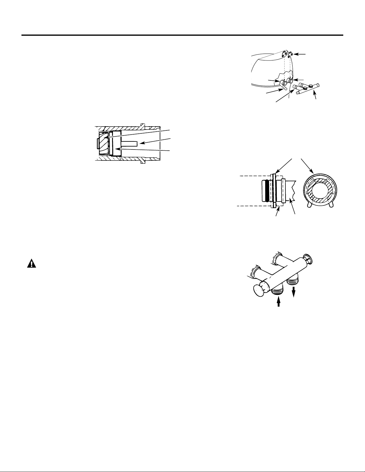
Fig. 3A
Fig. 3B
Fig. 3C
IN
OUT
Turn bypass valve
upside down to
connect to floor
level plumbing
Valve body
inlet or outlet
Bypass valve
(push all the way in)
Clip
END
VIEW
Clip
Outlet
Inlet
O-ring seal goes into
the outer groove only.
The clip snaps into the
inner groove (see below).
Bypass
valve
SIDE
VIEW
Step-by-step installation instructions.
■ Turn off the gas or electric supply to the water heater, in the possibility
that the water heater may be drained while draining pipes.
■ Turn off the water supply to pipes to be cut and drain the house
water pipes.
■ Open both hot and cold faucets at the lowest location possible.
Release 2 clips at rear of cover. Rotate cover forward and lift up.
NOTE: For easier installation, remove the top cover.
1. INSTALL BYPASS VALVE
• Remove plastic shipping plug and wire from valve outlet.
• Push the bypass valve (lubricate o-ring seals with silicone grease)
into both ports of the valve as shown in Fig. 3A.
• Snap the 2 large plastic clips in place, from the top, down as shown
in Figures 3A and 3B. Be sure they snap into place. Pull on the
bypass valve to make sure it is held securely in place.
2. MOVE THE SOFTENER ASSEMBLY INTO INSTALLATION POSITION
Be sure the installation surface is level and smooth. Sharp objects
under the tank may puncture it. If needed, place the tank on a section
of 3/4″ thick (minimum) plywood. Then, place shims under the
plywood as needed to level the softener.
3. PLUMB “IN” AND “OUT” PIPES TO AND FROM SOFTENER
CAUTION: Observe all of the following cautions as you
connect inlet and outlet plumbing. See illustrations on page 5.
• BE SURE INCOMING HARD WATER SUPPLY IS DIRECTED TO THE
SOFTENER VALVE INLET PORT. If house water flow is from the left,
use a plumbing crossover as shown in Fig. 1, page 5. If the house water
flows up from the floor level, turn the bypass valve upside down as shown
in Fig. 3C.
• If making a soldered copper installation, do all sweat soldering before
connecting pipes to the bypass valve. Torch heat will damage plastic
parts.
• When turning threaded pipe fittings onto plastic fittings, use care not
to cross-thread.
• Use pipe joint compound on all external pipe threads.
• Support inlet and outlet plumbing in some manner (use pipe hangers)
to keep the weight off of the valve fittings.
NOTE: Be sure the turbine and
support are firmly in place in the
valve outlet. Blow into the valve
port and observe the turbine
for free rotation.
Turbine
Valve outlet
Turbine shaft
and support
Drain Fitting
Page 7
7
GEAppliances.com
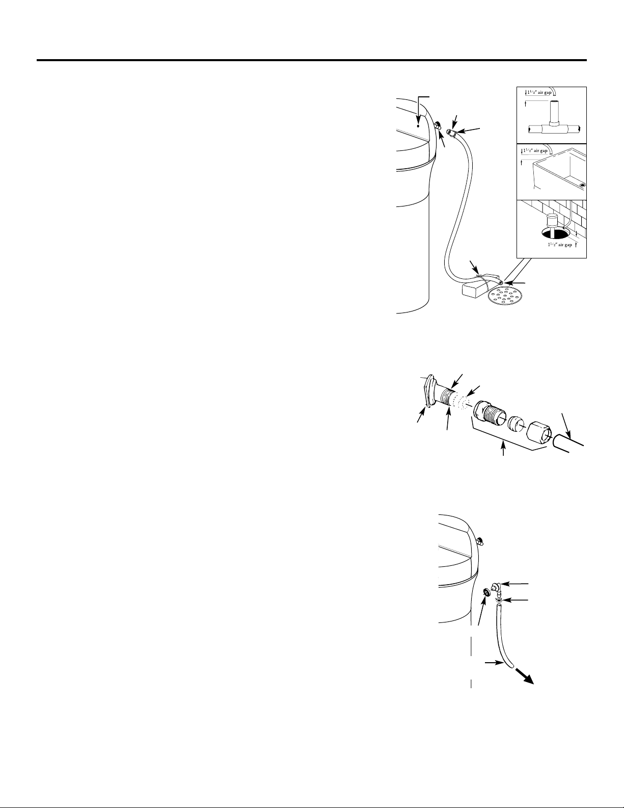
Fig. 4A
Fig. 5
To sewer drain
Overflow
drain hose
Hose clamp
Grommet
Clip
1/4″ NPT threads
Barbs
1/2″ O.D.
copper tube
(not furnished)
Cut barbs
from drain
fitting
Compression fitting,
1/4″ NPT X 1/2″ O.D. tube
(not furnished)
Do not connect to
valve drain hose.
Hose adapter
Fig. 4
Drain
fitting
on valve
Valve drain hose
FLOOR DRAIN
Tie or wire
hose in place
11⁄2″ air gap
LAUNDRY TUB
SUMP
Clamp
STANDPIPE
Blue indicator light
4. CONNECT AND RUN THE VALVE DRAIN HOSE
• Use the provided drain hose (20′ length included) to attach to the
valve drain fitting. To keep water pressure from blowing the hose off,
use a hose clamp to secure in place. Cut the necessary length and use
the remainder in Step 5.
• Locate the other end of the hose at a suitable drain point (floor drain,
sump, laundry tub, etc.) that terminates at the sewer. Check and comply
with local codes.
IMPORTANT: If more drain hose is needed, it should be ordered from
GE Parts at 800.626.2002. The water softener will not work if water
cannot exit this hose during recharge.
• Tie or wire the hose in place at the drain point. High water pressure will
cause it to whip during the back-wash and fast rinse cycles of recharge.
Also provide an air gap of at least 11⁄2″ between the end of the hose and
the drain point. An air gap prevents possible siphoning of sewer water
into the softener, if the sewer should “back-up.”
• Elevating the drain hose may cause back pressure that could reduce
the brine draw during recharge. If raising the drain line overhead is
required to get to the drain point, measure the inlet water pressure to
the softener first. For inlet pressures between 20 and 50 psi, do not raise
higher than 8′ above the floor. For inlet pressure above 50 psi, the drain
line may be raised to a maximum height of 14′.
4A. CONNECTING A RIGID VALVE DRAIN TUBE
To adapt a copper drain tube to the softener, use a hacksaw to cut the
barbed end from the drain fitting as shown in Fig. 4A. Rotate the drain
fitting so the cutting blade clears the valve housing to prevent damage to
valve. Buy a compression fitting (1/4″ female pipe thread x 1/2″ O.D. tube)
and needed tubing from your local hardware store.
5. INSTALL THE BRINE TANK OVERFLOW FITTINGS AND HOSE
• Insert the rubber grommet into the 3/4″ diameter hole in the brine
tank sidewall as shown in Fig. 5.
• Push the end of the hose adapter elbow into the grommet as shown
in Fig. 5.
• Attach a length of hose (use remaining hose from Step 4) to the hose
adapter elbow. Use a hose clamp to hold it in place.
• Locate the other end of the hose at the drain point. DO NOT ELEVATE
this hose higher than the elbow on the brine tank.
IMPORTANT: DO NOT TEE OVERFLOW HOSE TO VALVE DRAIN HOSE.
NOTE: This drain is for safety only. If the cabinet (brine tank) should
over-fill with water, the excess is carried to the drain.
Page 8
8
Step-by-step installation instructions.
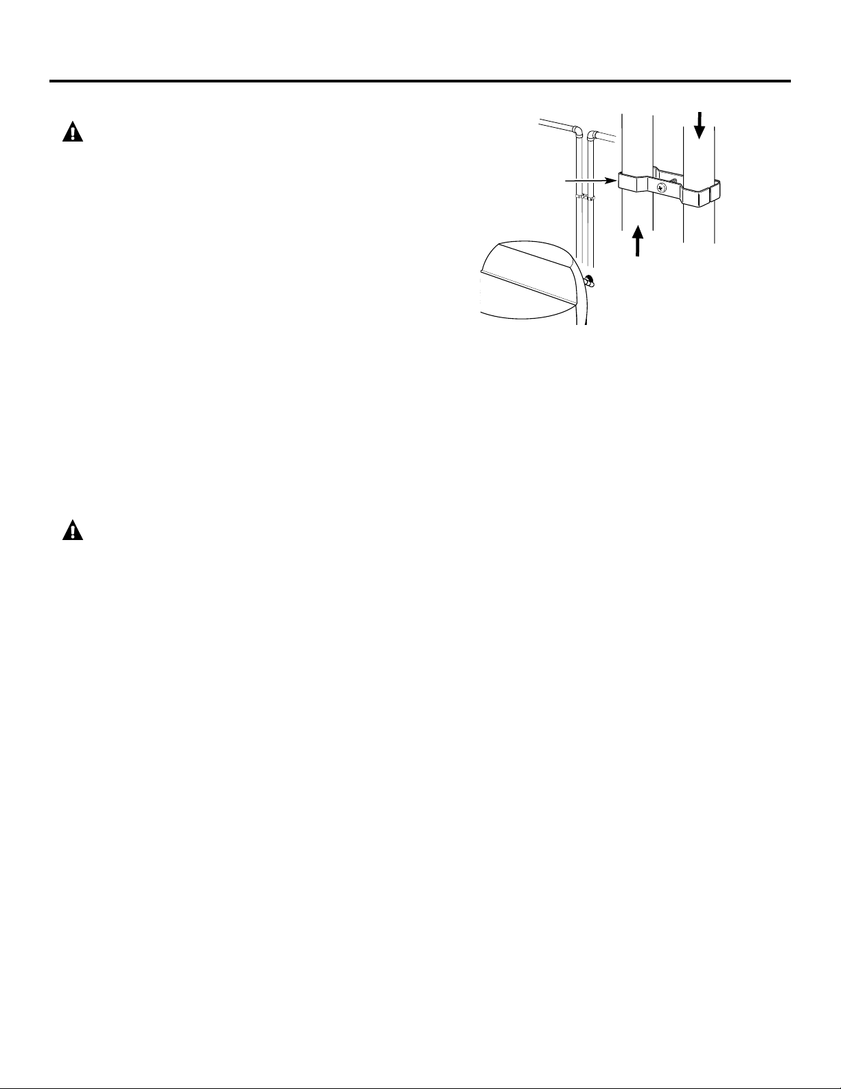
6. INSTALL GROUNDING CLAMP
DANGER: Failure to properly attach ground
clamp could result in electrical shock.
If plumbing is metal, to maintain electrical ground
continuity in the house cold water piping, install the
included ground clamps as shown in Fig. 6.
• Clean pipe with emery paper in the area where the
clamp is to be installed.
• Install grounding clamps as shown, making sure
ground clamps fit freely around pipe.
• Make sure lock washer is in place.
• Handtighten screw, then one more full turn with
screwdriver.
NOTE: When replacing an existing softener, also replace
grounding clamps.
If removing softener completely, hard-plumb the water
line with same type of pipes as the original to assure
plumbing integrity and ground continuity over the life
of the home.
7. FLUSH PIPES, EXPEL AIR FROM SOFTENER AND
TEST YOUR INSTALLATION FOR WATER LEAKS
CAUTION: To avoid water or air pressure
damage to softener inner parts, be sure to do the
following steps in exact order.
• Fully open 2 cold soft water faucets nearby the softener.
• Place bypass valve in “bypass” position by pushing the
stem inward.
• Fully open the house main water pipe shutoff valve.
Observe a steady flow from both faucets opened in
the step above.
• Place bypass valve in the “service” position EXACTLY
as follows. KEEP SOFT WATER FAUCETS OPEN.
• SLOWLY pull or slide the valve stem (out) toward the
service position, pausing several times to allow the
softener to pressurize slowly.
• After about 3 minutes, open a HOT water faucet
for 1 minute, or until all air is expelled, then close.
NOTE: If water appears cloudy or has salty taste,
allow to run for several more minutes, or until clear.
• Close all water faucets.
• Check your plumbing work for leaks and fix right
away if any are found. Be sure to observe previous
caution notes.
• Turn on the gas or electric supply to the water heater.
Light the pilot, if applicable.
8. ADD WATER AND SALT TO THE BRINE TANK
• Lift the salt hole cover. Add about 3 gallons of water
into the tank. Do not add into the brinewell.
• Fill tank with NUGGET, PELLET or coarse SOLAR
water softener salt with a purity of 99.5% or higher.
Do not use rock, block, granulated and ice creammaking salts, or salt with iron-removing additives
(except for Diamond Crystal®Red•Out®brand salt).
Maximum salt storage capacity is approximately 200 lbs.
Keep the salt hole cover closed unless servicing the unit
or refilling with salt.
NOTE: If the softener is installed in a humid basement or
other damp area, it is better to fill the tank with less salt,
more frequently. Eighty to 100 lbs. of salt will last for
several months, depending on water hardness, family size
and water softening system model.
9. CONNECT TO ELECTRICAL POWER
To gain access to the transformer/power cord assembly,
remove the salt hole cover from the softener. Unclip the
tabs on the rear of the top cover and rotate the cover
upwards to remove. DO NOT PULL OR DISCONNECT
WIRING.
• The softener works on 24 volt-60Hz electric power. The
included transformer changes standard 120-volt AC
house power to 24 volts. Plug the transformer into a
120-volt outlet only. Be sure the outlet is always live so
it can not be switched off by mistake.
• Replace the top cover.
• Replace the salt hole cover.
Fig. 6
Ground clamp
From valve outlet
To valve inlet
Page 9
9
GEAppliances.com
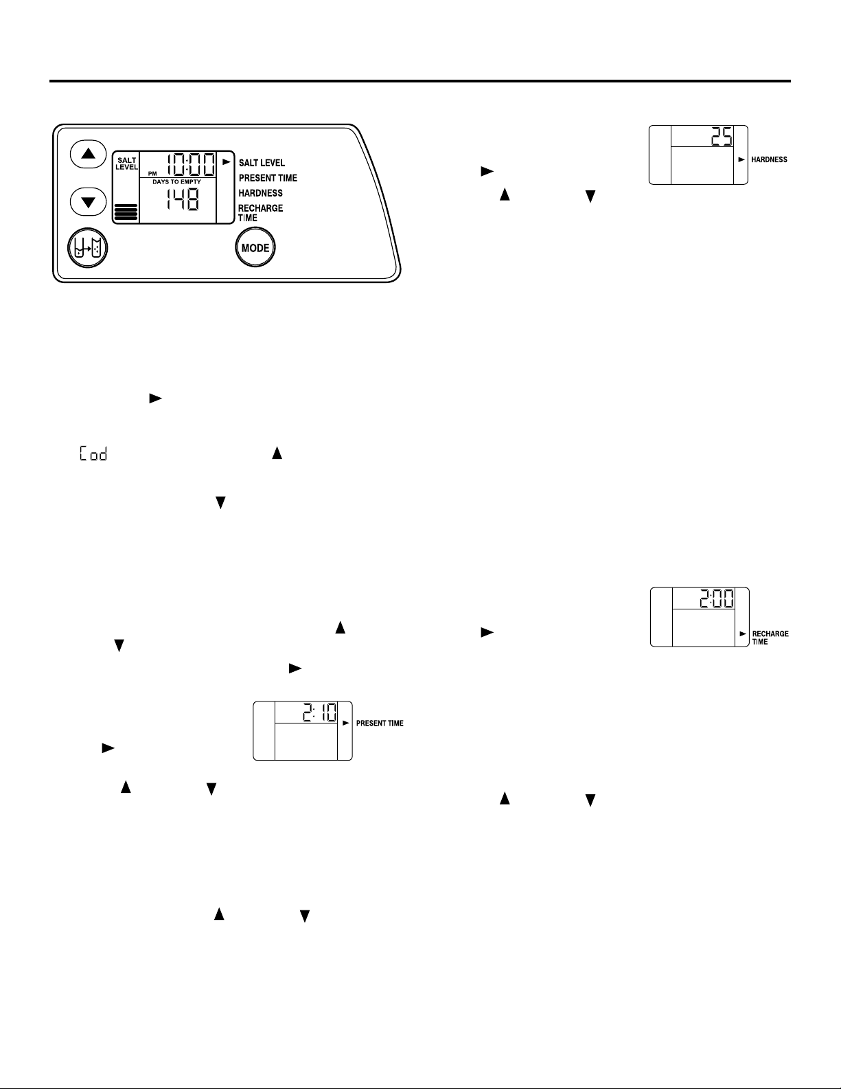
Programming the Control
CONTROL SETTINGS REQUIRED upon installation
and after an extended power outage.
NOTES:
■ WHEN THE TRANSFORMER IS PLUGGED INTO
THE ELECTRICAL OUTLET, 12:00 PM (flashing),
and an arrow is displayed next to PRESENT TIME
on the faceplate decal. The blue indicator light will
also flash. Program the control as instructed below.
■ If - - - is flashing, use the UP button to set
the correct F or H code as follows: F35 for GXSF35E
or F39 for GXSF39E. If you pass by the correct code
number, use the DOWN button. Then press the
MODE button to accept the correct model.
■ A “beep” sounds while pressing buttons for control
programming. One beep signals a change in the
control display. Repeated beeps mean the control
will not accept a change from the button you have
pressed, and you should select another button.
■ To program the control, you will use the UP ,
DOWN and MODE buttons.
■ Use the MODE button to scroll arrow to desired
control function.
SET PRESENT TIME OF DAY
1. Press the MODE button until
arrow points to PRESENT
TIME.
2. Press UP or DOWN button to set. The UP button
advances the time; the DOWN button moves the time
in reverse.
2. If the present time is between noon and midnight,
be sure PM shows in the display. If the present time
is between midnight and noon, be sure AM shows in
the display.
NOTE: Each press of an UP or DOWN button changes
the time by one minute. Holding the button changes the
time at a rapid rate.
3. When the present time is correct, press MODE to accept.
SET WATER HARDNESS NUMBER
1. Press the MODE button until
arrow points to HARDNESS.
2. Press UP or DOWN button
to set your water hardness number in the display. DOWN
decreases the hardness value. UP increases the hardness
value.
NOTE: Each press of a button changes the display by 1,
between 1 and 25. Above 25, the display changes 5 at a time
(25, 30, 35, etc.). Holding a button in changes the numbers
at a rapid rate.
3. When the display shows your water hardness (in grains
per gallon), press MODE to accept.
NOTE: If there is clear water iron in your water supply,
you will need to increase the hardness setting by 5 for
each 1 ppm of clear water iron in your water supply.
You can get the grains per gallon (gpg) hardness of your
water supply from a water analysis laboratory. If you are
on a municipal supply, call your local water department.
Or call Legend Technical Services, an independent
laboratory, to request a water hardness test kit at
1.800.826.8553, extension 47. If your report shows
hardness in parts per million (ppm) or milligrams per liter
(mg/l), simply divide by 17.1 to get the equivalent number
of grains per gallon.
SET RECHARGE (STARTING) TIME
1. Press the MODE button until
arrow points to RECHARGE
TIME.
NOTE: A flashing 2:00 AM (factory default) should show in
the display. This is a good time for recharge to start (takes
about 2 hours) in most households because water is not
in use. HARD WATER is bypassed to house faucets during
recharge.
If no change is needed, go to step 3. To change the
recharge starting time, follow step 2.
2. Press UP or DOWN button to set the desired
recharge start time. Be sure to observe the AM or PM
as you did when setting the time of day.
NOTE: Each press of a button changes the time by 1 hour.
Holding the buttons in changes the time at a rapid rate.
3. Press the MODE button to accept.
SALT
LEVEL
PM
SALT
LEVEL
AM
SALT
LEVEL
Page 10
10
Step-by-step installation instructions.
Programming the Control (cont.)
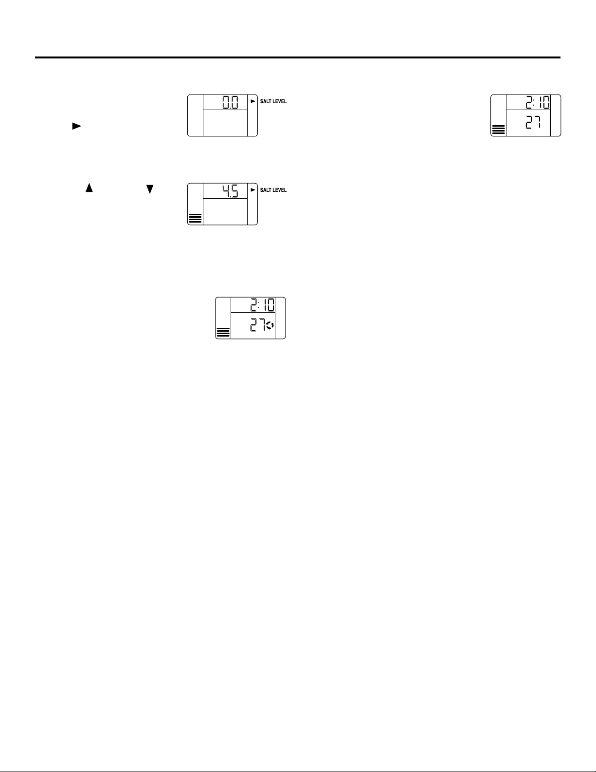
SET SALT LEVEL
1. Press the MODE button until
arrow points to SALT LEVEL.
2. Determine level of salt in brine tank using yellow
indicator on side of brine well, inside brine tank
(see illustration on page 5).
3. Press UP or DOWN
button to set the SALT LEVEL
to correspond to level on
yellow indicator in brine tank.
NOTE: Each press of a button changes the level by
increments of 0.5 up to 8.0. As the number increases,
the salt level bars increase on each whole number.
Lowering the salt level below zero turns the SALT LEVEL
indicator OFF.
4. Press the MODE button to accept. The
display shows the present time of day
and DAYS TO EMPTY. RECHARGE
TONIGHT may appear if unit is new.
DAYS TO EMPTY
The words DAYS TO EMPTY and a number
are shown in the lower half of the display.
This information is shown in the normal
run display. This is to inform the user of the number of days
before the salt level in the brine tank reaches Level 0.
There will be salt left in the salt tank, but it may not be
sufficient to fully recharge the system. Salt should be added
at this time to avoid hard water. The value is updated daily
and whenever the SALT LEVEL value is changed.
NOTE: For the first several weeks of operation, the DAYS TO
EMPTY may provide erratic operation. For example, the
blue indicator light may flash, showing that more salt is
required, when the actual salt level in the tank is well above
the Level 0. In some cases, the DAYS TO EMPTY may even
increase over a several week period.
It takes a couple of months for the water softener to learn
your water usage pattern. Once it does this, it will accurately
determine actual salt usage pattern. During this period,
check salt level when blue indicator light flashes. If the salt
level in the tank is at Level 1 or above, allow system to run.
Be sure to reset your salt level indicator each time you add
salt to the system.
SALT
LEVEL
SALT
LEVEL
SALT
LEVEL
PM
DAYS TO EMPTY
RECHARGE TONIGHT
SALT
LEVEL
PM
DAYS TO EMPTY
E
Page 11
GEAppliances.com
11
Optional Control Settings
The controller display has several options and features.
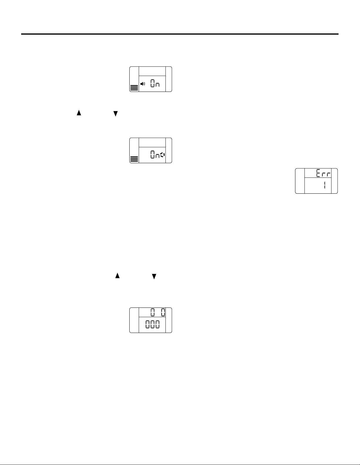
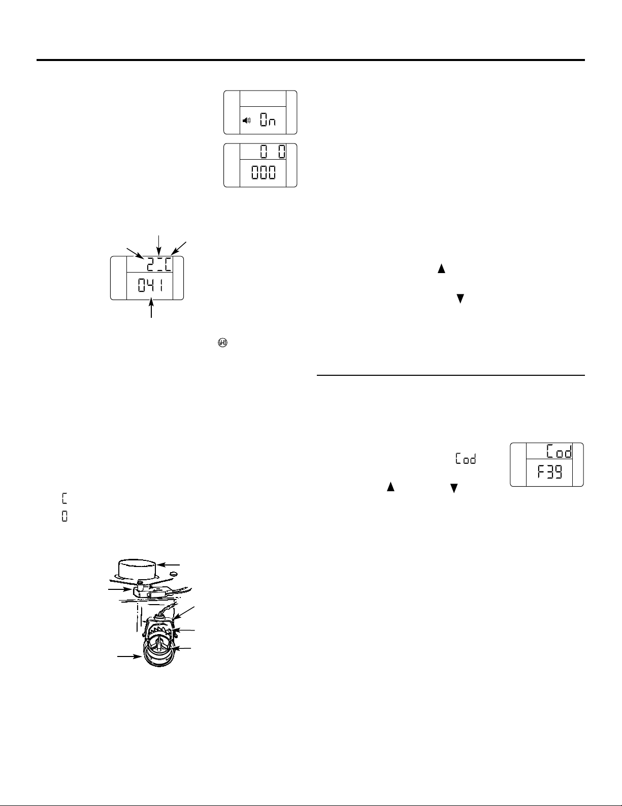
LOW SALT ALARM
The LOW SALT ALARM, when enabled,
will sound the beeper when the DAYS
TO EMPTY value is 15 days or less. To
change this setting, press and hold the MODE button for
3 seconds. ON (factory default) or OFF will flash in the
display. Press the UP or DOWN buttons to toggle
this feature ON or OFF. Press the MODE button to accept,
and the display will move to SALT EFFICIENCY.
SALT EFFICIENCY
When the SALT EFFICIENCY feature
is ON, the unit will operate at a salt
efficiency of at least 4000 grains of
hardness removed per pound of salt. This mode of
operation is the most efficient setting for salt usage,
because the system will tend to recharge more often,
with less salt usage. Turning the feature OFF will tend
to lengthen the time between recharge cycles, which will
provide the most efficient usage of water, but may use
more salt. The degree of difference between these
two cycles is highly dependent on the water usage and
hardness at a particular installation.
If you have very hard water, and you find your system
is regenerating every 1-2 days, turn the SALT EFFICIENCY
to OFF to lengthen the time between regenerations.
NOTE: California Regulations require this feature to be
ON for installations in California.
To change the setting, press the UP or DOWN
buttons to toggle the feature ON or OFF. Press the
MODE button to accept. The display will move to
SYSTEM/ELECTRONIC DIAGNOSTICS.
SYSTEM/ELECTRONIC DIAGNOSTICS
This display contains system
diagnostics information to assist in
troubleshooting problems with the
system. See pages 15–18 for details.
Press the MODE button to return to
the normal run display.
LOST TIME SIGNAL
If time is lost on the display due to power interruption, the
blue indicator light will flash 4 times every second, until the
present time of day is entered.
LOW SALT SIGNAL
When the DAYS TO EMPTY drops to 15, the blue indicator
light and DAYS TO EMPTY in the display will flash every
second and the alarm will beep every 30 seconds (from
8:00 AM to 8:00 PM), to notify the user that the unit is
running low on salt. As soon as any button is pressed,
the alarm will stop beeping. The blue indicator light and
DAYS TO EMPTY will continue to flash. Once salt is added
to the brine tank and the SALT LEVEL is reset, the DAYS TO
EMPTY will be reset.
ERROR SIGNALS
If there is an error code detected, the
blue indicator light will flash 4 times
every second, the display will flash Err
and the alarm will beep every 30 seconds (from 8:00 AM
to 8:00 PM), to signal that the softener requires service.
The alarm can be turned off by pressing any button, but
the blue indicator light and display will continue to flash.
See page 16 for information to assist in troubleshooting
error codes. Once the problem is corrected, disconnect the
transformer from the wall outlet momentarily, and plug it
back in. The normal display will appear. The motor may
run for several minutes, as the unit resets. If the problem is
not corrected, the error code will reappear in 6 minutes.
BLUE INDICATOR LIGHT
Steady blue light indicates that the unit is working
correctly. The light flashes when the unit needs attention
from the user.
• Light flashes and DAYS TO EMPTY flashes—check salt level
and add salt as required.
• Light flashes and Err is in the display—electrical problem
with system—see page 16.
• Light will also flash when power to the unit has been
interrupted. Check the PRESENT TIME setting.
SALT
LEVEL
SALT
LEVEL
E
SALT
LEVEL
SALT
LEVEL
Page 12
These systems conform to NSF/ANSI 44 for the specific capacity claims as verified and substantiated by test data.
* Testing was performed using pellet grade sodium chloride as the regenerant salt.
** Efficiency rating is valid only at the lowest stated salt dosage. These softeners were efficiency rated according to
NSF/ANSI 44.
*** Extent of iron removal may vary with conditions. The capacity to reduce clear water iron is substantiated by
WQA test data. State of Wisconsin requires additional treatment if water supply contains greater than 5 ppm
clear water iron. Use of Diamond Crystal
®
Red•Out®or Super Iron Out®will improve iron removal. Refer to
Cleaning Iron Out of the Water Softening System section.
**** Canada working pressure limits: 1.4–7.0 kg/cm
2
.
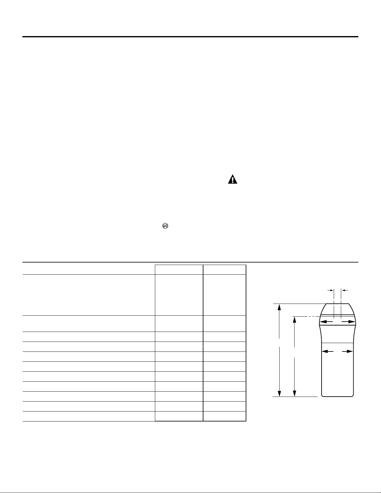
33⁄8″
OUTLET
INLET
INLET–OUTLET
471⁄2″
41
1
⁄4″
16″
Step-by-step installation instructions.
Sanitizing Procedures
To complete the installation, do the following
sanitizing procedures.
Care is taken at the factory to keep your
water softener clean and sanitary. Materials
used to make the softener will not infect or
contaminate your water supply and will not
cause bacteria to form or grow. However,
during shipping, storage, installing and
operating, bacteria could get into the
softener. For this reason, sanitizing as
follows is suggested when installing.
NOTE: Sanitizing is recommended by the
Water Quality Association for disinfecting.
1. Be sure to complete all installation steps,
including programming the control.
2. Pour about 3/4 oz. (11⁄2 tablespoons) of
common 5.25% unscented household bleach
(Clorox, Linco, Bo Peep, White Sail, Eagle,
etc.) into the brinewell. Refer to illustration
on page 5.
3. IMPORTANT: Press and hold for 3 seconds
the faceplate RECHARGE button to start
an immediate recharge. RECHARGE begins to
flash in the display. The bleach will be drawn
through the water softener and out the drain.
This process takes approximately 2 hours.
4. If, after sanitization, water from the house
faucet tastes salty or has a slight color, this is
a preservative from the resin tank. Turn on
the cold soft water faucets and drain for a
few minutes or until clear.
NOTE: When the sanitizing recharge is over,
all remaining bleach is flushed from the
conditioner and your house COLD water supply
is fully soft immediately. However, your water
heater is filled with hard water and as hot water
is used, it will refill with soft water. When all the
hard water is replaced in the water heater, hot
only and mixed hot and cold water will be fully
soft. If you want totally soft water immediately,
after the above recharge, drain the water heater
until the water runs cold.
WARNING:If you do drain the
water heater, use extreme care as the hot
water could cause burns. Turn the water
heater off prior to draining.
Specifications/Dimensions
19″
GXSF35E GXSF39E
Rated Capacity* 14,000 grains with 15,300 grains with
2.8 lbs. of salt 3.0 lbs. of salt
29,600 grains with 32,800 grains with
8.8 lbs. of salt 9.6 lbs. of salt
35,200 grains with 39,100 grains with
14.7 lbs. of salt 16.1 lbs. of salt
Rated Efficiency** 5,000 grains/lb. 5,100 grains/lb.
@ 2.8 lbs. of salt @ 3.0 lbs. of salt
Amount of High Capacity Resin (lbs/cu. ft) 47.8/0.92 52.5/1.01
Resin Tank Nominal Size (in., dia. x height) 9 x 40 9 x 40
Service Flow Rate (gpm) 8.5 8.0
Water Supply Maximum Hardness (gpg) 100 110
Water Supply Maximum Clear Water Iron (ppm)*** 6 8
Water Pressure Limits (min.–max. psi)**** 20–125 20–125
Pressure Drop at Rated Service Flow (psig) 15 15
Water Temperature Limits (min.–max. °F) 40–120 40–120
Maximum Flow Rate to Drain (gpm) 2.0 2.0
12
Page 13

13
About the water softener system.
GEAppliances.com
Service
When the water softening system is providing
soft water, it is called “Service.” During service,
hard water flows from the house main water
pipe into the water softening system. Inside the
water softening system resin tank is a bed made
up of thousands of tiny, plastic resin beads. As
hard water passes through the bed, each bead
attracts and holds the hard minerals. This is
called ion-exchanging. It is much like a magnet
attracting and holding metals. Water without
hard minerals (soft water) flows from the water
softening system and to the house pipes.
After a period of time, the resin beads become
coated with hard minerals and they have to be
cleaned. This cleaning is called recharge.
Recharge is started at 2:00 AM (factory setting)
by the water softening system control, and
consists of five stages or cycles. These are
FILL, BRINING, BRINE RINSE, BACKWASH and
FAST RINSE.
For emergency needs, hard water is available
to the home during the recharge cycles.
However, you should avoid using HOT water
because the water heater will fill with the
hard water.
Automatic Hard Water Bypass During Recharge
Fill
Salt dissolved in water is called brine. Brine is
needed to clean the hard minerals from resin
beads. To make the brine, water flows into the
salt storage area during the fill stage.
Brining
During brining, brine travels from the salt
storage area into the resin tank. Brine is the
cleaning agent needed to remove hard minerals
from the resin beads. The hard minerals and
brine are discharged to the drain.
The nozzle and venturi create a suction to
move the brine, maintaining a very slow rate
to get the best resin cleaning with the least salt.
Brine Rinse
After a pre-measured amount of brine is used,
the brine valve closes. Water continues to flow
in the same path as during brining, except for
the discontinued brine flow. Hard minerals and
brine flush from the resin tank to the drain.
Backwash
During backwash, water travels up through
the resin tank at a fast flow rate, flushing
accumulated iron, dirt and sediments from
the resin bed and to the drain.
Fast Rinse
Backwash is followed by a fast flow of water
down through the resin tank. The fast flow
flushes brine from the bottom of the tank,
and packs the resin bed.
After fast rinse, the water softening system
returns to soft water service.
Page 14
14
About the water softener system.
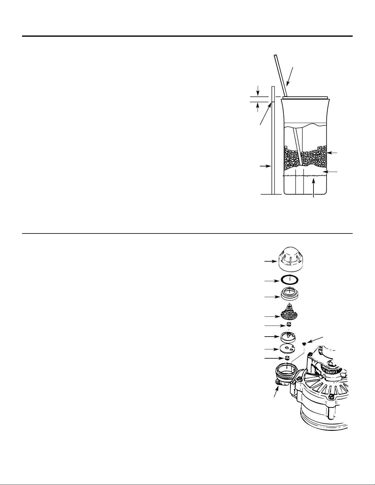
Breaking a Salt Bridge
Sometimes, a hard crust or salt bridge forms in
the salt storage area. It is usually caused by high
humidity or the wrong kind of salt. When the
salt bridges, an empty space forms between the
water and salt. Then salt will not dissolve in the
water to make brine.
If the brine tank is full of salt, it is hard to tell
if you have a salt bridge. Salt is loose on top,
but the bridge is under it. The following is the
best way to check for a salt bridge.
Salt should be loose all the way to the bottom
of the tank. Take a broom handle or like tool,
and carefully push it down into the salt,
working it up and down. If the tool strikes
a hard object (be sure it’s not the bottom or
sides of the tank), it’s most likely a salt bridge.
Carefully break the bridge with the tool.
Do not pound on the walls of the tank.
If the wrong kind of salt made the bridge, take
it out. Then fill the tank with nugget or pellet
salt only. In humid areas, it is best to fill with
less salt, more often to prevent a salt bridge
from forming.
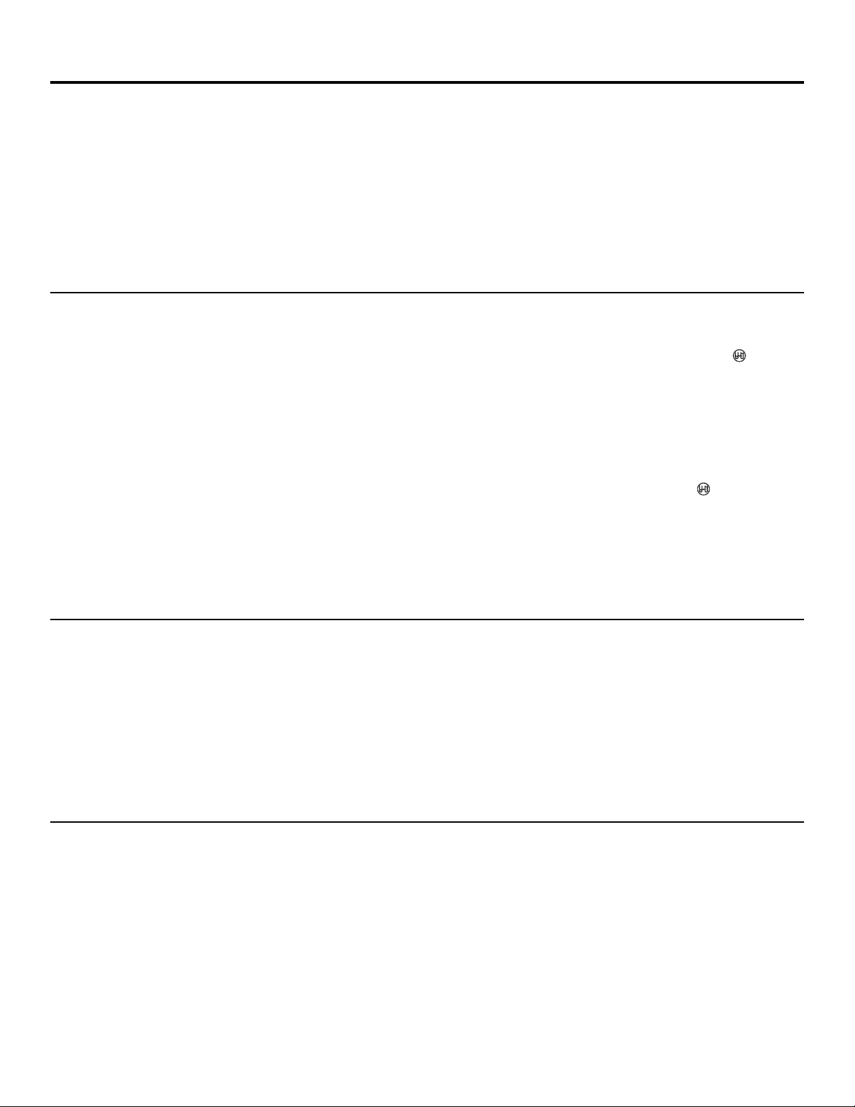
A clean nozzle and venturi is needed for the
water softening system to work properly. This
small unit makes the suction to move brine
from the salt storage area to the resin tank
during recharge. If it becomes plugged with
sand, dirt, etc., the water softening system
will not work and you will get hard water.
To get to the nozzle and venturi, remove
the water softening system top cover. Be sure
the water softening system is in service cycle
(no water pressure at nozzle and venturi).
Then, while holding the nozzle and venturi
housing with one hand, remove the cap. Lift
out the screen support and screen, then the
nozzle and venturi. Wash and rinse the parts in
warm water until clean. If needed, use a small
brush to remove iron or dirt. Also check and
clean the gasket.
NOTE: Some models have a small flow plug
located in the nozzle and venturi, and/or
a small cone shaped screen in the housing.
Be sure to check and clean these parts,
if your model is so equipped.
Carefully replace all parts in the correct order.
Lightly lubricate the o-ring seal with clean
silicone grease or petroleum jelly and place in
position. Install and tighten the cap, by hand only.
Do not overtighten the cap.
Cleaning the Nozzle and Venturi Assembly
Push tool into salt
bridge to break
Pencil
mark
Broom
handle
Salt
Salt
bridge
Water level
1″–2″
IMPORTANT: Be sure small holes in the gasket are
centered directly over the small holes in the nozzle and
venturi housing.
*Install with numbered side up, concave side down.
Cap
O-ring seal
Screen support
Screen
Screen
Nozzle & Venturi
Nozzle & Venturi
housing
Gasket
*Flow plug
*Flow plug
Page 15
15
GEAppliances.com
During normal operation, the present time of
day and AM or PM and DAYS TO EMPTY show
in the control display area. When the demand
computer determines a recharge is needed,
RECHARGE TONIGHT begins to flash in the
display along with the present time. RECHARGE
TONIGHT flashes until the next recharge start
time; then changes to RECHARGE, which flashes
until the recharge is over.
Normal Operation, Control Displays
Sometimes, a manually started recharge may
be desired or needed. Two examples:
■ You have used more water than usual
(house guests, extra washing, etc.) and
you may run out of soft water before the
next recharge.
■ The system ran out of salt.
Use one of the following features to start
a recharge immediately, or at the next preset
recharge start time.
RECHARGE TONIGHT
Touch (do not hold) the RECHARGE button.
RECHARGE TONIGHT flashes in the control
display area. A recharge will occur at the next
preset recharge start time. If you decide to
cancel this recharge, touch the same button
once more.
RECHARGE
Press and hold the RECHARGE button until
RECHARGE starts to flash in the control display
area. The water softening system begins an
immediate recharge and, when over in about
two hours, you will have a new supply of soft
water. Once started, you cannot cancel this
recharge.
Feature: Optional Recharge Controls
Feature: Memory
If electrical power to the water softening system
is interrupted, the control display is blank, and
the blue indicator light is off, but the control
keeps correct time for about 6 hours. When
power is restored, you have to reset the present
time only if the display and blue indicator light
are flashing. All other settings are maintained
and never require resetting unless a change
is desired.
If the time is flashing after a long power outage,
the water softening system continues to work
as it should to provide you with soft water.
However, recharge may occur at the wrong time
of day until you reset the control to the correct
time of day.
The control computer has a self-diagnostic
function for the electrical system (except
input power and water meter). The computer
monitors the electronic components and
circuits for correct operation. If a malfunction
occurs, an error code appears in the
control display.
The chart on Error Codes shows the error codes
that could appear and possible reasons for each
code. See Manually Initiated Electronic Diagnostics
to further isolate the defect.
Feature/Service: Automatic Electronic Diagnostics
Page 16

16
To remove an error code: 1. Unplug transformer.
2. Correct defect.
3. Plug transformer in.
4. Wait for at least 6 minutes. The error code will return if the reason for
the error code was not corrected.
NO SOFT
WATER
CONTROL SHOWS
WRONG TIME AND DAY,
AND/OR IS FLASHING.
CONTROL
DISPLAY
BLANK.
CONTROL DISPLAY SHOWS
CORRECT TIME AND DAY
AND IS STEADY.
Check electrical
power to control
(outlet, transformer,
power cable, all
connections).
Do manual
diagnostics.
NO POWER
POWER OK
REPAIR AS
NEEDED
CONTROL
DEFECTIVE
Do manual
diagnostics to
verify proper
function.
Electrical power was off.
Reset the correct time of
day.
Investigate reason for
power loss.
About the water softener system.
Service: Electronic Demand Time Features and Service
If you are not getting soft water, and an error
code is not displayed, use the procedures below
to find the problem. First make the following
visual checks.
VISUAL CHECKS:
1. Is there electrical power to the outlet the
water softening system transformer is
plugged into?
2. Is there sufficient salt in the storage tank?
3. Is the softener bypass valve directing water
for soft water service?
4. Is the valve drain hose open to the drain,
not more than 8′ above the softener, and
unobstructed? If hose is above 8′, see page 7,
section 4.
If you do not find a problem with the visual checks,
continue below.
Service: Timer/Softener, Service Checkout Procedure
ERROR CODE
DISPLAYED ERR 01 ERR 02 ERR 03 ERR 04 ERR 05
POSSIBLE DEFECT • Motor • Position • Motor • Position • Control
inoperative switch inoperative switch or
or wiring wiring
harness harness
• Wiring • Control • Control • Control
harness or
connection
to switch
• Position
switch
• Control
Page 17
17
GEAppliances.com
1. To enter diagnostics, press and hold
the MODE button for 3 seconds until
the LOW SALT ALARM screen shows.
2. Press the MODE button 2 times to
advance through LOW SALT ALARM
and SALT EFFICIENCY options. See
Programming the Control for details
on these two options.
3. OPERATION OF DIAGNOSTICS
• Valve Position—Press the RECHARGE button to
initiate a recharge cycle. Press again to manually index
valve to next position. See Service: Manually Advance
Recharge Check for details.
0 – Service
1 – Fill
2 – Brine
3 – Backwash
4 – Fast Rinse
• Motor Operation—Two dashes will circulate around
when motor should be running.
• Position Switch Operation—
– Closed—valve rotating to next position
– Open—valve in position, service, fill, brine, etc.
• Water Meter—Indicates whether water is flowing
through valve.
– 000 indicates no water is flowing through the valve
– Open nearby soft water faucet
– 000 to 199 (continual) shows water is flowing. Display
repeats for each gallon of water passing through the
meter. Control will beep at every gallon.
– If there is no reading in the display, with faucet
open, check the sensor. Pull the sensor from the
valve outlet port, and pass a small magnet in front
of the sensor. Counter should index in the display.
If counter does not index, check to make sure
harness is connected to board properly. If there is
a reading in the display, there may be a problem
associated with the turbine. Turn off water supply,
close the by-pass valve, and disconnect by-pass valve
from valve body. Check turbine for binding or
restriction due to debris. If this does not correct
the problem, the Timer, Sensor or Turbine may
require replacement.
4. Historical data about the softener is available.
• Press and hold the UP button to display the number
of days this control has had electrical power applied.
• Press and hold the DOWN button to display the
number of recharges initiated by this control since the
model code number was entered.
5. Press the MODE button to return to normal operation
and display.
Service: Set Model (F or H) Code
1. To change or check model code, first press and hold the
MODE button for 3 seconds until the LOW SALT ALARM
screen shows.
2. Press and hold the MODE button again
for 3 seconds. A display with at
the top will appear.
3. Press the UP or DOWN buttons
to select the correct model code.
SR22–GXSF27E, F31–GXSF31E, F35–GXSF35E,
F39–GXSF39E, H39–GXSH39E, H45–GNSH45E
4. Press the MODE button one time to return to normal
operation and display. If the model code was changed:
• the display will go blank momentarily, then display the
model code entered.
• the display will then return to the set present time
display, and the blue indicator light will flash. The
control will have to be reprogrammed. See Programming
the Control.
NOTE: If the control is left in any of the above diagnostic
displays, or a flashing display when setting time, hardness,
etc., it will revert back to the normal display in 4 minutes.
Service: Manually Initiated Electronics Diagnostics
Water meter
Valve
position
Position
switch
Motor
Motor
Turbine
Turbine support
and shaft
Sensor
housing
Position
switch
Valve
outlet
SALT
LEVEL
SALT
LEVEL
SALT
LEVEL
SALT
LEVEL
Page 18
18
About the water softener system.
NOTE: The control display must show a steady
time (not flashing).
1. Press the RECHARGE button and hold in
for three seconds. RECHARGE begins to flash
as the water softening system enters the fill
cycle of recharge. Remove the brinewell
cover and, using a flashlight, observe fill
water entering the brine tank. If water does
not enter the tank, look for an obstructed
nozzle, venturi, fill flow plug or brine tubing.
See Care and Cleaning of the Water Softener
System section.
2. After observing fill, press the RECHARGE
button to move the water softening system
into brining. A slow flow of water to the drain
will begin. Verify brine draw from the brine
tank by shining a flashlight into the brinewell
and observing a noticeable drop in the liquid
level over an extended period of time.
NOTE: Be sure a salt bridge is not preventing
water from contacting salt. See Care and
cleaning of the water softening system section.
If the water softening system does not draw brine,
check:
■ nozzle and/or venturi dirty or defective.
■ defective nozzle and venturi seal.
■ nozzle and venturi not seated properly
on gasket.
■ other inner valve defect (rotor seal, rotor
and disc, wave washer, etc.).
■ restricted drain (check drain fitting and
hose).
NOTE: If water system pressure is low, an
elevated drain hose may cause back pressure,
stopping brine draw.
3. Again, press the RECHARGE button to move
the water softening system into backwash.
Look for a fast flow of water from the drain
hose. A slow flow indicates a plugged top
distributor, backwash flow plug or drain hose.
4. Press the RECHARGE button to move the
water softening system into fast rinse. Again
look for a fast drain flow. Allow the water
softening system to rinse for a few minutes
to flush out any brine that may remain in
the resin tank from the brining cycle test.
5. To return the water softening system to
service, press the RECHARGE button.
Service: Manually Advance Recharge Check
Page 19
19
Care and cleaning of the water softening system.
GEAppliances.com
Brine (salt dissolved in water) is needed for
each and every recharge. The water for making
brine is metered into the salt storage area by
the water softening system valve and control.
However, you must keep the tank supplied
with salt.
When to refill with salt: If the blue indicator
light and DAYS TO EMPTY are flashing, there is
less than 15 days supply of salt. Refill with salt.
In humid areas it is best to refill with less salt
and more often, to avoid the forming of a
salt bridge (see page 14). After adding salt,
remember to reset the SALT LEVEL in the
control (see page 10). Never allow the salt
level to drop below zero on the yellow indicator
before you refill it. Without enough salt, you
will soon have hard water.
Use clean water softening salts only, at least
99.5% pure. NUGGET, PELLET or coarse
SOLAR salts are recommended. Do not use rock,
block, granulated or ice cream making salts.
They contain dirt and sediments, or mush and
cake, and will create maintenance problems.
CAUTION:
Water softening salt with
iron removing additives: Some salts may have
an additive to help the water softening
system handle iron in the water supply.
Although this additive may help to keep the
water softening system resin clean, it may
also release corrosive fumes that weaken
and shorten the life of some water softening
system parts. GE recommends using only
Diamond Crystal
®
Red•Out®brand salt.
Checking the Salt Storage Level and Refilling
Your water softening system takes hardness
minerals (calcium and magnesium) out of
the water. Also, it can control some (see the
Specification Guidelines section) “clear water”
iron. With clear water iron, water from a faucet
is clear when first put into a glass. After 15 to
30 minutes, the water begins to cloud or turn
rust colored. A water softening system will not
remove any iron that makes the water cloudy
or rusty as it comes from the faucet (called red
water iron). To take red water iron out of water,
or over the maximum of clear water iron,
an iron filter or other equipment is needed.
GE recommends using only Diamond Crystal
®
Red•Out®brand salts with Iron Fighter
®
additive to help keep the resin bed clean of
clear iron. If your water supply has clear water
iron, periodic resin bed cleaning is needed.
GE recommends using Super Iron Out®brand
resin bed cleaner to thoroughly clean your
resin bed if your iron content is high. Clean
the bed at least every six months, or more
often if iron appears in the soft water between
cleanings.
IMPORTANT: It is important to mix the resin bed
cleaner with water (following the manufacturer’s
instructions), pour it into the brinewell tube
(see page 5) and recharge the softener
immediately. Do not pour the resin bed cleaner
in with the salt, as it will not be as effective in
cleaning the resin, and can cause damage to
the softener if it is left in the brine tank for an
extended period due to the corrosive gases that
are formed.
Cleaning Iron Out of the Water Softening System
Page 20
20
Troubleshooting Tips
Save time and money! Review the chart on following pages first
and you may not need to call for service.
Problem Possible Causes What To Do
No soft water Faucet or fixture where sample was •
To conserve salt, the installer
may have isolated some fixtures
taken not plumbed to soft water
(outside faucets, toilets, etc.)
from soft water. From the outlet
NOTE:
Be sure sample is from a faucet of the water softening system, trace the water flow path,
that does not mix soft and hard water. in house plumbing. If soft water is not directed to a faucet
For example, a single lever kitchen faucet, or
fixture where wanted, consult a plumber.
if the cold side is plumbed to hard water.
No salt in the brine tank or • Check for a salt bridge or, if the
tank is empty, refill with
salt bridged recommended salt. Press (for 3 seconds) the RECHARGE
button to start an immediate recharge and restore
soft water supply.
Transformer unplugged at wall outlet or
• Check for a loss of electrical power to the water softening
power cable to softener not connected. system, due to any of these conditions and correct as needed.
Fuse blown or circuit breaker popped With the power supply restored, observe the faceplate time
on circuit to electrical outlet. display and read Programming the Control section.
Electrical outlet on a circuit that can
NOTE: The electrical outlet for the softener should be continuously
be switched off
live
so it cannot be accidentally switched off.
Manual bypass valve in • Be sure the bypass valve stem
is positioned properly, with the
bypass position
knob in the OUT position. Observe i
nstructions on the decal
at the end of the stem.
Valve drain hose pinched, plugged, •
Any restriction in this drain hose
may prevent proper
elevated too high or otherwise
operation of the
nozzle and venturi and reduce or prevent
restricted brine draw during recharge.
Nozzle and venturi dirty, incorrectly • Refer to Cleaning the Nozzle and Venturi Assembly
instructions.
assembled or damaged
With water pressure to the
water softening system off, take
the nozzle assembly apart. Inspect, clean and replace as
needed. Any foreign particle(s), scratches, nicks, etc., in the
passages can
prevent operation. Be sure holes in the gasket are
centered over holes in the housing.
NO SOFT WATER—Most Common Problems:
Check the following before calling for service:
• Not enough salt—should be at least 1/3 full.
•
Bypass valve in “Bypass” position—knob should be in the “OUT” (service) position.
• Hardness setting too low—check hardness setting and adjust. Verify hardness of
supply water—from local water company, water test or call the GE Answer Center.
• Salt Bridge—salt solidifies above water level so that brine water is not in contact
with salt. See the Breaking a Salt Bridge section.
Before you call for service…
Page 21

21
Problem Possible Causes What To Do
Water hard sometimes Using hot water while the water • Avoid using hot water during water softening system recharge
softening system is regenerating because the water heater will refill with hard water. See
Automatic Hard Water Bypass During Recharge section, page 13.
Control HARDNESS number setting • Press the MODE button until arrow points to HARDNESS.
too low Be sure the number shown is the same as the actual grains
per gallon hardness of your water supply. See the
Programming the Control section if a change in the setting
is needed.
Grains of hardness in your water •
Water hardness can change
over time, especially in well water.
supply have increased To check, have the water tested by a water analysis laboratory
or call your local water department. Adjust the HARDNESS
number setting as needed.
Water feels slippery Absence of hardness minerals • This is normal. Hardness in water gives it the abrasive feel
after installation of you may have been accustomed to. The slippery feel is the
water softening system clean feel of soft water.
Water softening system Water softening system is a • Does not use much salt to regenerate—very efficient.
not using any salt “demand” unit
Possible salt bridge • See the About the Water Softener System section, page 14.
Possible plugged nozzle and venturi • See the About the Water Softener System section, page 14.
Water is blue color Acidic water in copper plumbing • Have the water tested at once.
after water softening
system was installed
Water softening system Meter turbine stuck • See the Service: Manually Initiated Electronics Diagnostics
not regenerating section for troubleshooting procedures, page 17.
• Call for service.
Sensor wire not plugged into • See the Service: Manually Initiated Electronics Diagnostics
the control section for troubleshooting procedures, page 17.
• Call for service.
No power to unit • Check the circuit breaker or fuses.
Mechanical defect • Call for service.
Cloudiness on glassware Combination of soft water and • This is called etching and is permanent. To prevent this
(automatic dishwashers) too much detergent from happening, use less detergent if you have soft water.
Wash glassware in the shortest cycle that will get them clean.
Excessive/high level Valve drain hose pinched, • Any restriction in this drain hose may prevent proper
of water in brine tank plugged, elevated too high operation of the nozzle and venturi and reduce or prevent
or otherwise restricted brine draw during recharge.
Nozzle and venturi dirty, incorrectly • See the Cleaning the Nozzle and Venturi Assembly section,
assembled or damaged page 14. With water pressure to the water softening system
off, take the nozzle assembly apart. Inspect, clean and
replace as needed. Any foreign particle(s), scratches, nicks,
etc., in the passages can prevent operation. Be sure holes
in the gasket are centered over holes in the housing.
GEAppliances.com
Page 22

22
Problem Possible Causes What To Do
Salty tasting or Unit not sanitized • Complete the Sanitizing Procedures on page 12.
brown/yellow colored
• At completion of recharge cycle (approx. 2 hrs), run water
water after installation
from faucets to purge the salty water.
Low water pressure Check pressure.
• Drain height 8′ or less, pressure should be minimum of 20 psi.
• Drain height above 8′, pressure should be minimum of 50 psi.
Restricted drain hose • Clean and reconnect hose.
• Check for kinks in drain line.
Brown/yellow Unit was idle for a period of time • Complete the Sanitizing Procedures on page 12.
colored water
Resin beads showing Cracked distributor • Call for service.
up in drinking water
and sink
Sounds you might hear Running water from the unit • This is normal.
into a drain during recharge
Water has air bubbles Air in system after installation • Will go away after it runs for a while.
and is cloudy
Error Code on control Wiring may have worked loose • See page 16 for details.
in the control
• Unplug transformer.
• Remove control cover, release clips on side.
• Check for loose/incorrect wiring connections to electronic
board or switch. Reconnect as required.
• Reassemble control cover.
• Plug in Transformer.
• Wait six minutes for Error Code to reappear.
• If Error Code reappears, call for service.
Troubleshooting Tips
Before you call for service…
Blue light flashing
When power applied Control needs to be programmed • See the Programming the Control section, page 9–10.
to the system (a power outage may have occurred)
If “DAYS TO EMPTY” Low salt level, less than 15 days • Fill with salt.
is flashing
•Reset salt level.
If “Err” in display Electrical problem with system • See page 16 for details.
•See procedure above, Error code on control.
Page 23

23
Notes.
GEAppliances.com
Page 24

24
Parts list.
Page 25

25
GEAppliances.com
Page 26

26
GENERAL ELECTRIC PARTS CATALOG
GG
XX
SS
FF
33
59
EE
REF. NO. PART NO. PART DESCRIPTION (01) (01)
0003 WS35X10001 O-RING SEAL KIT 1 1
0004 WS34X10015 DECAL, FACEPLATE 1 1
0005 WS07X10004 HOSE, DRAIN, 20 FT. 1 1
0007 WS14X10002 DISTRIBUTOR, TOP 1 1
0008 WS14X10001 DISTRIBUTOR, BOTTOM 1 1
0009 WS01X10002 RESIN, 1 CU. FT. 1 1
0010 WS32X10011 RESIN TANK, 9 X 40 1 1
0011 WS31X10022 COVER, TOP W/ LENS 1 1
0012 WS31X10023 FACEPLATE 1 1
0013 WS21X10013 CONTROL 1 1
0016 WS26X10013 TRANSFORMER WITH
POWER CORD 1 1
0017 WS31X10021 COVER, SALT HOLE,
WITH LABELS 1 1
0018 WS33X10001 VAPOR BARRIER 1 1
0019 WS33X10007 RIM 1 1
0020 WS31X10024 COVER, BRINEWELL W/ DECAL 1 1
0021 WS02X10009 NUT 1 1
0022 WS32X10017 BRINEWELL W/ DECAL 1 1
0023 WS02X10027 SCREW 1 1
0024 WS32X10016 TANK, BRINE, ROUND 1 1
0025 WS18X10003 CLAMP, HOSE 2 2
0026 WS22X10016 ADAPTER, HOSE 1 1
0027 WS22X10017 GROMMET 1 1
0028 WS35X10035 GROUND CLAMP KIT 1 1
0029 WS15X10035 BRINE VALVE ASM. 1 1
0030 WS35X10036 FLOAT, STEM & GUIDE 1 1
0031 WS03X10006 CLIP 1 1
0032 WS15X10006 VALVE BODY, BRINE 1 1
0033 WS03X10007 CLIP 1 1
0034 WS03X10008 SCREEN 1 1
0035 WS07X10002 TUBING ASM. 1 1
0036 WS07X10015 BRINE TUBE ASM. 1 1
0037 WS31X10018 BACK COVER, ELECTRONICS 1 1
0038 WS02X10029 SPACER 1 1
0039 WS02X10030 FACEPLATE SUPPORT 1 1
0055 WS28X10003 RETAINER CLAMP 2 2
0056 WS28X10004 CLAMP 2 2
0101 WS02X10012 SCREW 1 1
0102 WS02X10013 SPACER 1 1
0103 WS21X10003 SWITCH 1 1
0104 WS03X10009 PIN, EXPANSION 1 1
0105 WS02X10014 SCREW 5 5
0106 WS31X10006 COVER, VALVE 1 1
0107 WS03X10010 WAVE SPRING 1 1
0108 WS26X10002 ROTOR & DISC ASM. 1 1
0109 WS19X10004 CAP, VENTURI 1 1
0110 WS03X10011 SEAL, O-RING 1 1
Parts catalog.
Page 27

27
GEAppliances.com
GENERAL ELECTRIC PARTS CATALOG
GG
XX
SS
FF
33
59
EE
REF. NO. PART NO. PART DESCRIPTION (01) (01)
0111 WS19X10005 SUPPORT SCREEN 1 1
0112 WS03X10013 SCREEN 1 1
0113 WS22X10020 FLOW PLUG, .10 GPM 1 1
0114 WS08X10005 GASKET & ASPIRATOR 1 1
0115 WS03X10015 CONE SCREEN 1 1
0116 WS22X10021 PLUG, FILL FLOW, .30 GPM 1 1
0117 WS03X10017 FERRULE NUT 1 1
0118 WS15X10034 NOZZLE/VENTURI BODY 1 1
0119 WS03X10018 RETAINER 1 1
0120 WS03X10019 SEAL, O-RING, 1/4″ X 3/8″ 22
0121 WS15X10010 BODY, VALVE 1 1
0122 WS03X10020 SPRING 1 1
0123 WS22X10022 PLUG, DRAIN SEAL 1 1
0124 WS15X10009 NOZZLE/VENTURI ASM. 1 1
0130 WS35X10005 SEAL KIT, 3/4″ 11
0132 WS22X10023 ADAPTER, DRAIN HOSE 1 1
0133 WS03X10021 O-RING, 5/8″ X 13/16″ 11
0134 WS03X10022 PLUG, FLOW, RINSE CONTROL 1 1
0135 WS03X10023 CLIP 1 1
0136 WS26X10003 CAM & GEAR 1 1
0137 WS26X10004 BEARING 1 1
0138 WS26X10005 PLATE, MOTOR, 3/4″ 11
0139 WS02X10015 SCREW, #6-20 X 3/8″ 22
0140 WS26X10011 MOTOR ASM. 1 1
0141 WS02X10016 SCREW, #6-20 X 7/8″ 22
0142 WS60X10001 NUT, INSTALLATION 2 2
0143 WS60X10002 TUBE, INSTALLATION 2 2
0144 WS60X10003 WASHER 2 2
0145 WS60X10004 CLIP 2 2
0146 WS28X10017 HARNESS WIRE, SENSOR ASSY., 3/4″ 11
0147 WS19X10006 TURBINE & SUPPORT ASM. 1 1
0150 WS03X10024 SEAL, O-RING 1 1
0151 WS15X10012 BYPASS ASM. 1 1
0152 WS03X10025 SEAL, O-RING 2 2
0153 WS60X10006 ADAPTER 2 2
0999 49-50151 OWNER’S MANUAL 1 1
WS35X10037 INSTALLATION KIT 1 1
Page 28

28
For The Period Of: We Will Replace:
One Year Any part of the Water Softening System which fails due to a defect in materials or workmanship.
From the date of the During this full one-year warranty, GE will also provide, free of charge, all labor and in-home service
original purchase to replace the defective part. All warranty service will be provided by a GE SmartWater™Authorized
Service agent.
Three Years The electronic monitor, if it fails due to a defect in materials or workmanship. During this three-year
From the date of the limited warranty, you will be responsible for any labor or in-home service costs.
original purchase
Ten Years A replacement brine tank or cabinet, if either fails due to a defect in materials or workmanship.
From the date of the During this ten-year limited warranty, you will be responsible for any labor or in-home service costs.
original purchase
■ Service trips to your home to teach you how to use
the product.
■ Improper installation, delivery or maintenance.
■ Failure of the product if it is abused, misused, or used for
other than the intended purpose or used commercially.
■ Defects that result from improper installation or damage
not caused by GE.
■ Liability on the part of GE under this or any other warranty
for any indirect or consequential damage.
■ Products that are used for commercial or industrial
applications.
■ Filters, membranes or batteries.
■ Replacement of house fuses or resetting of circuit breakers.
■ Damage to the product caused by accident, fire, floods or
acts of God.
■ Incidental or consequential damage caused by possible
defects with this appliance, its installation or repair.
■ Damage caused after delivery.
What Is Not Covered:
This warranty is extended to the original purchaser and any succeeding owner for products purchased for home use
within the USA. In Alaska, the warranty excludes the cost of shipping or service calls to your home.
Some states do not allow the exclusion or limitation of incidental or consequential damages. This warranty gives you
specific legal rights, and you may also have other rights which vary from state to state. To know what your legal rights
are, consult your local or state consumer affairs office or your state’s Attorney General. THIS WARRANTY IS INTENDED
TO BE IN LIEU OF ALL OTHER WARRANTIES, WHETHER EXPRESS OR IMPLIED, INCLUDING THE WARRANTIES OF
MERCHANTABILITY AND FITNESS FOR A PARTICULAR PURPOSE.
Warrantor: General Electric Company. Louisville, KY 40225
GE Water Softening System Warranty. (For Customers in the United States)
All warranty service provided by our SmartWater™Authorized
Servicer Network. To schedule service, on-line, 24 hours a day, visit
us at GEAppliances.com, or call 800.GE.CARES (800.432.2737) (U.S),
or 866.777.7627 (Canada).
Staple your receipt here.
Proof of the original purchase
date is needed to obtain service
under the warranty.
Page 29

29
All warranty service provided by our Factory Service Centers or an authorized technician.
For service, call toll free 1.866.777.7627.
What Is Not Covered:
■ Service trips to your home to teach you how to use
the product.
■ Improper installation.
If you have an installation problem, contact your dealer
or installer. You
are responsible for providing adequate
electrical, exhausting and other connecting facilities.
■
Replacement of house fuses or resetting
of circuit
breakers.
■ Failure of the product if it is misused, or used for other
than the intended purpose or used commercially.
■
Damage to product caused by accident,
fire, floods or
acts of God.
WARRANTOR IS NOT RESPONSIBLE FOR CONSEQUENTIAL DAMAGES.
Warrantor: CAMCO INC.
For The Period Of: We Will Replace:
One Year Any part of the Water Softening System which fails due to a defect in materials or workmanship.
From the date of the During this full one-year warranty, GE will also provide, free of charge, all labor and in-home service
original purchase to replace the defective part.
Three Years The electronic monitor, if it fails due to a defect in materials or workmanship. During this three-year
From the date of the limited warranty, you will be responsible for any labor or in-home service costs.
original purchase
Ten Years A replacement brine tank or cabinet, if either fails due to a defect in materials or workmanship.
From the date of the During this ten-year limited warranty, you will be responsible for any labor or in-home service costs.
original purchase
GE Water Softening System Warranty. (For Customers in Canada)
Page 30

Notes.
30
Page 31

Información de seguridad . . . . .32
Instrucciones para la
instalación . . . . . . . . . . . . . . .33–42
Instrucciones paso por paso . . .36–42
Instrucciones para la operación
Cómo limpiar la ensambladura
de la boquilla y el Venturi . . . . . . .45
Cómo romper un puente de sal . . .44
Funciones . . . . . . . . . . . . . . . . . . .46
Servicio . . . . . . . . . . . . . . . .43, 47–49
Sistema de descalcificación
de agua . . . . . . . . . . . . . . . . . .43–49
Cuidado y limpieza . . . . . . . . . . .50
Consejos para la solución
de averías . . . . . . . . . . . . . . . .51–54
Soporte al cliente
Garantía . . . . . . . . . . . . . . . . . . . . .62
Lista de partes/catálogo . . . . .56–59
Soporte al consumidor . . . . . . . . .63
Escriba aquí el modelo y los números
de la serie:
Modelo No. ______________________
Serie No. ________________________
Para encontrar estos números, levante
la cubierta y mire en el borde, debajo
del panel del control.
31
Page 32

INFORMACIÓN IMPORTANTE DE SEGURIDAD.
LEA TODAS LAS INSTRUCCIONES ANTES DEL USO.
PRECAUCIONES DE SEGURIDAD
■ Revise y cumpla con todos los códigos estatales y
locales. Observe las pautas aquí presentadas.
■ Tenga cuidado al manipular el sistema de
descalcificación de agua. No lo voltee, deje caer,
arrastre o coloque en protuberancias extremas.
■ Los sistemas de descalcificación de agua que
utilicen cloruro de sodio (sal) para la recarga
agregan sodio al agua. Las personas que siguen dietas
con restricciones de sodio deben considerar el sodio
adicional como parte de su consumo general. El cloruro
de potasio puede usarse como una alternativa para
el cloruro de sodio de su descalcificador.
■
El sistema de descalcificación de agua funciona
solamente con 24 voltios-60 Hz.
Cerciórese de usar
exclusivamente el transformador incluido.
■ El transformador se debe conectar únicamente
a un tomacorriente interior con conexión a tierra
de 120 voltios.
■ Utilice únicamente sales para descalcificación
del agua, al menos con 99.5% de pureza. Se
recomiendan las sales en PEPITAS, BOLITAS
o SAL GRUESA SOLAR. No utilice sales en roca,
bloque, granuladas o sales para la elaboración
de helados. Éstas pueden contener suciedad y
sedimentos, o pasta y masa y podrían crear
problemas de mantenimiento.
■ Mantenga la tapa del orificio de la sal en su lugar
en el descalcificador a menos que esté realizando
mantenimiento o reponiendo la sal.
ADVERTENCIA: No use con agua que
sea microbiológicamente insegura o de calidad
desconocida sin llevar a cabo la desinfección
adecuada antes o después del sistema.
LEA Y SIGA ESTA INFORMACIÓN DE SEGURIDAD CUIDADOSAMENTE.
GUARDE ESTAS INSTRUCCIONES
INSTALACIÓN CORRECTA
■ Instale o almacene donde no quede expuesto a
temperaturas por debajo del punto de congelación
ni esté expuesto a ningún tipo de inclemencias
atmosféricas. Si el agua llega a congelarse dentro
del sistema, éste podría romperse. No intente dar
tratamiento al agua si se encuentra a una
temperatura por encima de 38 ºC (100 ºF).
■ No instale expuesto a los rayos directos del sol.
Exposición al sol o calor excesivos podrían causar
distorsión u otros daños a las partes no metálicas.
■ Conecte a tierra de manera apropiada según los
códigos y ordenanzas aplicables.
■ Use solamente fundente y soldadura sin plomo para
todas las conexiones de condensación soldadas,
según los códigos estatales y federales aplicables.
■
El sistema de descalcificación de agua requiere un
flujo de agua mínimo de tres galones por minuto en
la entrada. La presión de entrada máxima permitida
es de 125 psi. Si la presión durante el día es por
encima de 80 psi, la presión nocturna podría exceder
el máximo. Use una válvula reductora de presión
para reducir el flujo si es necesario.
■
Las resinas de descalcificación podrían degradarse
ante la presencia de cloro por encima de 1 ppm.
Si usted tiene una cantidad de cloro mayor a ésta,
quizás experimente una vida menor de la resina.
En estas condiciones, es posible que quiera
considerar la compra de un sistema de filtración
del punto de admisión para casas GE con un filtro
reductor de cloro.
ADVERTENCIA:Deseche todas las
partes y los materiales de embalaje no utilizados
después de la instalación. Partes pequeñas
restantes después de la instalación podrían
representar un peligro de asfixia.
Este sistema de descalcificación de agua debe instalarse correctamente y colocarse de acuerdo a las
instrucciones de instalación antes de su uso.
32
Por su seguridad, se debe seguir la información en este manual con el fin de reducir el riesgo de una
descarga eléctrica, daños a la propiedad o daños personales.
ADVERTENCIA
Page 33

33
PRECAUCIÓN: Se necesita cierta habilidad de plomería para la instalación.
Si usted no está seguro acerca de la instalación de alguna de las partes de este producto,
consulte a un plomero profesional.
Instrucciones de instalación.
GEAppliances.com
Desempacado e inspección
Cerciórese de inspeccionar completamente el
descalcificador en busca de daños durante el
envío o partes que puedan haberse perdido.
También revise en busca de daños en la caja
de envío. Póngase en contacto con la compañía
de transporte para cualquier reclamo por daño
o pérdida. El fabricante no es responsable por
daños sufridos durante el tránsito.
Las partes pequeñas necesarias para instalar
el descalcificador se encuentran en una pieza
de cartón termoconformada o en una bolsa.
Para evitar la pérdida de las partes pequeñas,
manténgalas en el paquete hasta que esté
listo para usarlas. Cerciórese de no descartar
componentes que podrían estar escondidos
en el embalaje.
■ Antes de comenzar la instalación, lea estas
Instrucciones de instalación completamente.
Luego, obtenga todos los materiales y
herramientas que necesita para llevar a cabo
la instalación. No instalar correctamente el
descalcificador invalida la garantía.
■ Revise los códigos locales. La instalación
debe cumplir tales requisitos.
■ En el estado de Massachusetts, la instalación
debe ajustarse al Código de Plomería 248 CMR.
Consulte a su plomero certificado.
■ Use solamente fundente y soldadura sin
plomo para todas las conexiones de
condensación soldadas, según los códigos
estatales y federales aplicables.
■ Conecte el descalcificador en la tubería
de suministro principal antes del
calentador de agua. NO HAGA PASAR
AGUA CALIENTE A TRAVÉS DEL
DESCALCIFICADOR. La temperatura
del agua que pase a través del
descalcificador debe ser menor de
49 ºC (120 ºF).
■ Tenga cuidado cuando manipule el
descalcificador. No lo coloque boca
arriba, ni lo deje caer, ni lo arrastre,
ni lo apoye en protuberancias.
■ La presión de entrada máxima permitida
es de 125 psi. Si la presión durante el día es
por encima de 80 psi, la presión nocturna
podría exceder el máximo. Use una válvula
reductora de presión para reducir el flujo si
es necesario. (Agregar una válvula reductora
de presión podría reducir el flujo.)
■ El sistema de descalcificación funciona
solamente con 24 voltios-60 Hz. Cerciórese
de usar exclusivamente el transformador
incluido. Cerciórese de que el tomacorriente
eléctrico y el transformador están en el
interior de un recinto para protegerlos de
la humedad.
■ Consulte la sección Dónde instalar el
descalcificador para más detalles.
ADVERTENCIA:No use con
agua que sea microbiológicamente
insegura o de calidad desconocida sin
llevar a cabo la desinfección adecuada
antes o después del sistema. El agua debe
probarse periódicamente para verificar
que el sistema se encuentra funcionando
satisfactoriamente.
■ Partes pequeñas restantes después de la
instalación podrían representar un peligro
de asfixia. Deseche con toda seguridad.
Recomendaciones importantes para la instalación
Lea el manual completo. Ignorar las directrices y reglas podría causar lesiones personales o
daños a la propiedad.
Page 34

34
Instrucciones de instalación.
Dónde instalar el Descalcificador
■ Coloque el descalcificador lo más cercano
posible a un sumidero, o a otro punto de
drenaje o columna de suministro.
■ Se recomienda que los grifos externos se
dejen con agua dura para así ahorrar agua
descalcificada y sal.
■
No instale el descalcificador en un lugar
donde se pueda congelar. Los daños debido al
congelamiento no están cubiertos por la garantía.
■ No instale el descalcificador donde pueda
bloquear el acceso al calentador de agua o el
acceso a la válvula de cierre principal del agua.
■ Coloque el descalcificador en un lugar donde
sea menos probable que ocurra daño causado
por el agua si es que eventualmente ocurriese
alguna fuga. El fabricante no reparará ni pagará
por daños ocasionados por agua.
■ Un tomacorriente de 120 voltios es necesario
para conectar el transformador que viene
incluido. El descalcificador tiene un cable
eléctrico de 10 pies. Si el tomacorriente está
colocado demasiado lejos (hasta 100 pies),
use un cable calibre 18 para conectarlo.
Cerciórese de que el tomacorriente eléctrico y el
transformador estén en el interior de un recinto
para protegerlos de la humedad. Cerciórese de
que el tomacorriente esté desconectado para
prevenir un corte eléctrico accidental.
■ Si se dispone a llevar a cabo la instalación en
el exterior, debe tomar las medidas necesarias
para asegurarse de que el descalcificador, la
instalación de plomería, el cableado, etc. están
bien protegidos de los elementos (rayos del sol,
lluvia, viento, calor, frío), de la contaminación,
vandalismo, etc. tal y como lo estarían si fueran
instalados internamente. La instalación en el
exterior no es recomendada, y anula la garantía.
■ Mantenga el descalcificador alejado de los rayos
directos del sol. El calor del sol podría causar
distorsión u otros daños a las partes no
metálicas y podría hacer daño a las partes
electrónicas.
■ Los accesorios de entrada y salida incluidos
con el descalcificador son tubos de cobre de
condensación de 3/4″ (1,91 cm)—nominal.
Debe mantener un tamaño igual o mayor de
tubos que los tubos del suministro del agua,
hacia la entrada y salida del descalcificador.
■ Use la válvula de bypass incluida para instalar el
descalcificador. La válvula de bypass le permite
desconectar el suministro de agua hacia el
descalcificador para efectuar servicio, pero aún
mantiene el agua llegando a las tuberías de la
casa. Los accesorios de entrada y salida a que
nos referimos anteriormente se conectan a la
válvula de bypass con las tuercas y arandelas
incluidas.
■ Use accesorios y tuberías de cobre, latón o
galvanizados. Algunos códigos podrían permitir
el uso de tuberías plásticas CPVC.
■ Si una manguera adicional es necesaria para el
drenaje de la válvula y el tanque de sal, usted la
puede solicitar en Accesorios GE llamando al
800.626.2002.
■ Si necesita una válvula rígida de drenaje para
cumplir con los códigos de plomería, podrá
comprar las partes necesarias para conectar
un drenaje de tubería de cobre o plástico de
1/2″ (1,27 cm).
■ Sal del descalcificador en una pepita limpia o
bolita de agua es necesaria para llenar el tanque
de agua salmuera, consulte las Instrucciones de
Instalación Paso por Paso en el Paso 8.
Herramientas y materiales necesarios para la instalación
Lo primero que debe decidir es cómo instalar las
tuberías que entran y salen del descalcificador.
Fíjese en la tubería de agua en el punto donde
conectará el descalcificador. ¿La tubería está
soldada con cobre, pegada con plástico, o roscada
galvanizada? ¿Cuál es el tamaño de la tubería?
ADVERTENCIA: Use solamente
fundente y soldadura sin plomo para todas las
conexiones de condensación soldadas, según
los códigos estatales y federales aplicables.
Consulte la Ilustración de instalación normal, Fig. 1.
Úsela como una guía para planificar su instalación
particular. Cerciórese de dirigir el suministro de
agua dura entrante al acoplamiento de admisión
de la válvula del descalcificador. La válvula está
marcada IN (ENTRADA) y OUT (SALIDA). Consulte
la ilustración en la página 35 como ayuda para la
preparación.
Planifique la instalación del Descalcificador
Page 35

35
GEAppliances.com
Ilustración de instalación normal
Agua descalcificada
Agua dura hacia
los grifos externos
TUBERÍA DE AGUA PRINCIPAL
Agua dura
NOTA: Ver la sección Conexiones de la manguera de drenaje.
Transformador
de 24V
Tomacorriente
de 120 voltios
Válvula de
bypass
Agua dura hacia
los grifos externos
Válvula de
entrada
Válvula de
salida
Sistema de derivación
de 3 válvulas
Para el servicio de agua
descalcificada:
• Abra las válvulas de entrada
de salida
• Cierre la válvula de bypass
Para circunvalar el agua dura:
• Cierre las válvulas de
entrada y salida
• Abra la válvula de bypass
Tapa del
orificio
de la sal
LA SAL
VA AQUÍ
Depósito
de la
salmuera
ENTRADA
Arandela (2)
Tubo de cobre de 3/4″ (1,91 cm) (2)
Tuerca de instalación (2)
Válvula de bypass
• Tire hacia afuera para servicio de agua
descalcificada
• Empuje para bypass
NOTA: Los accesorios proporcionados son para
plomería de cobre de 3/4″ (1,91 cm). Si usted
tiene plomería de 1″ (2,54 cm), no use los
tubos de cobre y las tuercas incluidas. Compre
adaptadores hembras NPT de 1″ (2,54 cm) y
conéctelos directamente a las roscas macho
NPT de 1″ (2,54 cm) de la válvula de bypass.
Tuerca (2)
Tubo de cobre de 3/4″ (1,91 cm) (2)
Arandela (2)
Adaptador de instalación (2) (ver arriba)
NOTA: Los accesorios proporcionados son para
plomería de cobre de 3/4″ (1,91 cm). Si usted
tiene plomería de 1″ (2,54 cm), no use los
tubos de cobre y las tuercas incluidas. Compre
adaptadores hembras NPT de 1″ (2,54 cm) y
conéctelos directamente a las roscas macho
NPT de 1″ (2,54 cm) de los adaptadores.
ENTRADA
Unión (no incluida) (2)
Ilustración de la instalación opcional de una derivación de 3 válvulas
Los adaptadores para esta instalación no vienen incluidos con el descalcificador. Para ordenar estos adaptadores, llame a GE Parts al
800.626.2000. (Solicite la parte # WS60X10006.)
Fig. 1
VÍA DE ENLACE
Úsela si el flujo de suministro fluye
desde la izquierda. Incluya una derivación
sencilla o de 3 válvulas.
Agua
dura
De la
salida del
descalcificador
Agua
descalcificada
Hacia la entrada
del descalcificador
TUBERÍA DE AGUA PRINCIPAL
Agua dura
Agua descalcificada
Tomacorriente
de 120 voltios
Transformador
de 24V
Depósito
de la
salmuera
LA SAL
VA AQUÍ
Tapa del
orificio de
la sal
Fig. 2
VÍA DE ENLACE
Úsela si el flujo de suministro fluye
desde la izquierda. Incluya una derivación
sencilla o de 3 válvulas.
Agua dura
De la
salida del
descalcificador
Agua
descalcificada
Hacia la
entrada del
descalcificador
Drenaje
Drenaje
Page 36

Clip
Salida
Entrada
El sello del aro tórico va
en la muesca externa
solamente. El clip engrapa
en la muesca interna (ver
más adelante).
Válvula de
bypass
Accesorio de drenaje
36
Fig. 3A
Fig. 3B
Fig. 3C
ENTRADA
SALIDA
Gire la válvula
de bypass boca
arriba para
conectar a la
tubería al nivel
del piso.
Cuerpo de la válvula
de entrada o salida
Válvula de bypass
(empújela al máximo)
Clip
VISTA
POSTERIOR
VISTA
LATERAL
Instrucciones de instalación paso por paso.
■ Suspenda el suministro de gas o de energía eléctrica que alimenta el
calentador de agua, en la posibilidad de que el calentador pueda drenarse
mientras usted drena las tuberías.
■ Desconecte el suministro de agua hacia los tubos que han de ser cortados y
drene las tuberías de agua de la casa.
■ Abras ambos grifos, el de agua fría y el de agua caliente en el lugar más
bajo posible. Libere los dos clips en la parte posterior de la cubierta.
Rote la cubierta hacia adelante y levante.
NOTA: Para una instalación más fácil, remueva la cubierta superior.
1. INSTALE LA VÁLVULA DE BYPASS
• Remueva el tapón plástico de embalaje y el cable de la salida de la válvula.
• Empuje la válvula de bypass (lubrique los aros tóricos con grasa de
silicona) hacia ambas boquillas de la válvula como se muestra en
la Fig. 3A.
• Enganche los dos clips plásticos en sus posiciones, a partir de la parte
superior y hacia abajo, como se muestra en las Figs. 3A y 3B. Cerciórese
de engancharlos en sus lugares apropiados. Tire de la válvula de bypass
para cerciorarse de que se encuentra sostenida con seguridad en su lugar.
2. MUEVA LA ENSAMBLADURA DEL DESCALCIFICADOR HACIA SU
POSICIÓN DE INSTALACIÓN
Cerciórese de que la superficie de instalación se encuentre nivelada y lisa.
Cualquier objeto cortante debajo del tanque podría causar una hendidura
en el mismo. Si es necesario, coloque el tanque sobre una sección de
plywood de un grueso mínimo de 1,91 cm (3/4″). Luego, coloque cuñas
debajo del plywood según sea necesario para nivelar el descalcificador.
3. CONECTE LAS TUBERÍAS QUE ENTRAN Y SALEN DEL DESCALCIFICADOR
PRECAUCIÓN:Siga todas las precauciones siguientes
mientras conecta la plomería de entrada y salida. Vea las ilustraciones
en la página 35.
• CERCIÓRESE DE QUE EL SUMINISTRO DE AGUA DURA ESTÁ
DIRECTAMENTE CONECTADO AL PUERTO DE LA VÁLVULA DE
ENTRADA DEL DESCALCIFICADOR DE AGUA. Si el flujo del agua de
la casa es desde la izquierda, use un crossover de tubería como se muestra
en la Figura 1, página 34. Si el flujo del agua de la casa fluye hacia arriba
desde el nivel de piso, voltee la válvula de bypass boca abajo como se
muestra en la Figura 3C.
• Si se dispone a llevar a cabo una instalación con soldadura de cobre,
haga todas las soldaduras de condensación antes de conectar los tubos
a la válvula de bypass. El calor de antorcha dañará las partes plásticas.
• Cuando se encuentre girando accesorios de tubería roscados en
accesorios plásticos, cerciórese de no cruzar las roscas.
• Use un compuesto de junta de tuberías en todas las roscas externas.
• Apoye la tubería de entrada y de salida de alguna manera (use colgadores
de tubería) para evitar que el peso se deposite sobre los ajustes de las
válvulas.
NOTA: Cerciórese de que la
turbina y el soporte se encuentren
firmes en sus posiciones en la
salida de la válvula. Sople hacia
la boquilla de la válvula y observe
que la turbina se encuentra
rotando libremente.
Turbina
Salida de la válvula
Eje y soporte
de la turbina
Page 37

37
GEAppliances.com
Fig. 4
Válvula de la manguera
de drenaje
DRENAJE
DE PISO
Ate o amarre
la manguera
en su lugar
Espacio de
tolerancia de
3,8 cm (1
1
⁄2″)
Abrazadera
Luz indicadora azul
4. CONECTE Y HAGA FUNCIONAR LA MANGUERA DE DRENAJE
DE LA VÁLVULA
• Use la manguera de drenaje (se ha incluido una de 20 pies) para
adherirla al accesorio de drenaje de la válvula. Para evitar que la presión
del agua expulse la manguera, use una abrazadera de mangueras para
asegurarla en su lugar. Corte la longitud necesaria y use la parte restante
en el Paso 5.
• Ubique el otro extremo de la manguera en un punto apropiado
para drenar (drenaje de piso, sumidero, tina de lavandería, etc.)
que termine en el sistema de alcantarillado. Cerciórese de cumplir
con los códigos locales.
IMPORTANTE: Si necesita más manguera de drenaje, ordénela llamando
al Departamento de Partes de GE al 800.626.2002. El descalcificador de
agua no funciona si el agua no escapa por esta manguera durante las
generaciones.
• Ate o amarre la manguera en un lugar cercano al punto de drenaje.
Una alta presión de agua podría causar que el extremo de la manguera
se mueva erráticamente durante los ciclos de lavado regresivo y enjuague
rápido de la generación. También deje una tolerancia de aire de al
menos 3,8 cm (11⁄2″) entre el extremo de la manguera y el punto de
drenaje. Este espacio previene que ocurra un efecto sifón del agua de
alcantarillado hacia el descalcificador, si ocurriese un ciclo de lavado
regresivo.
• Elevar la manguera de drenaje podría causar una presión negativa que
podría reducir la toma del contenido de sal durante las generaciones.
Si fuera necesario levantar la manguera de drenaje hasta un nivel superior
al descalcificador para llegar hasta el punto de drenaje, mida primero
la presión de entrada de agua hacia el descalcificador. Para las presiones
de entrada entre 20 y 50 psi, no eleve más de 8 pies (2,67 m) por encima
del piso. Para la presión de entrada por encima de 50 psi, la manguera
de drenaje podría levantarse a una altura máxima de 14 pies.
4A. CÓMO CONECTAR UN TUBO DE DRENAJE DE VÁLVULA RÍGIDA
Para adaptar un tubo de drenaje de cobre al descalcificador, use una
sierra de arco para cortar el extremo de púa del accesorio de drenaje,
tal y como se muestra en la Fig. 4A. Rote el accesorio de drenaje de forma
tal que la hoja de corte evite el alojamiento de la válvula para prevenir
daños a la válvula. Compre un accesorio de compresión (tubo hembra
de rosca de 1/4″ [0,63 cm] x 1/2″ [1,27 cm] de diámetro externo) y
los tubos necesarios en una ferretería local.
5. INSTALE LOS ACCESORIOS DE SOBREFLUJO DEL TANQUE DE
SALMUERA Y LA MANGUERA
• Inserte una arandela de goma en el agujero de 3/4″ (1,9 cm) de diámetro
en el lado del tanque de salmuera como se muestra en la Fig. 5.
• Empuje el extremo del codo adaptador de la manguera hacia la
arandela como se muestra en la Fig. 5.
• Adhiera la manguera (use la manguera que sobre del Paso 4) al codo
adaptador de la manguera. Use una abrazadera de mangueras para
mantenerla firmemente en su lugar.
• Ubique el otro extremo de la manguera en el punto de drenaje.
NO ELEVE esta manguera más allá del codo en el tanque de salmuera.
IMPORTANTE: NO SOBREFLUYA EN T LA MANGUERA HACIA LA MANGUERA
DE DRENAJE DE LA VÁLVULA.
NOTA: Este drenaje es para seguridad solamente. Si el gabinete (el tanque de
salmuera) se llena demasiado de agua, el agua excesiva se lleva al drenaje.
Accesorio
de drenaje
en la válvula
Fig. 4A
Fig. 5
Hacia el drenaje
de la alcantarilla
Manguera
de drenaje
de sobreflujo
Abrazadera de
la manguera
Arandela
Clip
Roscas NPT de
1/4" (0,63 cm)
Lengüetas
Tubo de cobre de
1/2″ (1,27 cm) de
diámetro externo
(no incluido)
Corte las lengüetas
del accesorio de
drenaje
Accesorio de compresión, tubo de
1/4″ (0,63 cm) NPT X 1/2″ (1,27 cm)
de diámetro externo (no incluido)
No conectar la manguera
de drenaje de la válvula
Adaptador de
la manguera
TUBO REGULADOR
SUMIDERO
LAVADERO
Page 38

6. INSTALE LAS ABRAZADERAS DE TIERRA
PELIGRO:No adherir apropiadamente la
abrazadera de tierra podría resultar en una descarga
eléctrica.
Si las tuberías son de metal, para mantener continuidad
de tierra eléctrica en la tubería de agua fría, instale las
abrazaderas de tierra incluidas como se muestra en la Fig. 6.
• Limpie la tubería con papel de esmerilar en el área donde
la abrazadera será instalada.
• Instale las abrazaderas de conexión a tierra como se
muestra, cerciorándose que las abrazaderas ajustan
libremente alrededor de la tubería.
• Cerciórese de que la arandela de cierre está en su lugar
• Apriete con sus manos el tornillo, luego una vuelta
completa adicional con el destornillador.
NOTA: Cuando reemplace un descalcificador existente,
también reemplace las abrazaderas de conexión a tierra.
Si se dispone a remover el descalcificador completamente,
coloque tuberías en las líneas de agua del mismo tipo que
las tuberías usadas originalmente para asegurar la integridad
de las tuberías y continuidad en la conexión a tierra a lo
largo de la vida de la casa.
7. PURGUE LAS TUBERÍAS, SAQUE EL AIRE DEL
DESCALCIFICADOR Y PRUEBE SU INSTALACIÓN
EN BÚSQUEDA DE FUGAS DE AGUA
PRECAUCIÓN: Para evitar daños por la
presión de agua o de aire en las partes internas del
descalcificador, cerciórese de dar los pasos siguientes
en el mismo orden en que se presentan.
• Abra completamente 2 grifos de agua descalcificada
fría en grifos cercanos al descalcificador.
• Abra la válvula de bypass en la posición “bypass”
empujando el vástago hacia adentro.
• Abra completamente la válvula de cierre de la tubería
del agua principal de la casa. Observe un flujo fijo de
ambos grifos abiertos en el paso A, anteriormente.
• Coloque la válvula de bypass en la posición de
“servicio”, en la forma EXACTA como le especificamos
a continuación. MANTENGA LOS GRIFOS DE AGUA
DESCALCIFICADA ABIERTO.
• LENTAMENTE tire o deslice el vástago de la válvula
(hacia afuera) hacia “servicio”, pausando varias veces
para permitir que la presurización del descalcificador
comience lentamente.
• Después de unos 3 minutos, abra un grifo de agua
CALIENTE por 1 minuto, o hasta que todo el aire haya
sido extraído, luego ciérrelo. NOTA: Si parece que el agua
está turbia o tiene un sabor salado, permita que el sistema
funcione por unos minutos más, o hasta que se aclare.
• Cierre todos los grifos de agua.
• Inspeccione en búsqueda de fugas en la tubería que se
acaba de llevar a cabo y repare inmediatamente si
encuentra alguna. Cerciórese de observar las notas de
precaución anteriores.
• Conecte el suministro de gas o eléctrico hacia el calentador
de agua. Encienda el piloto si es aplicable.
8. AGREGUE AGUA Y SAL AL TANQUE DE SALMUERA
• Levante la tapa del orificio de la sal. Agregue
aproximadamente 3 galones de agua al tanque.
No la agregue al depósito de salmuera.
• Llene el tanque con sal de PEPITAS, BOLITAS o SAL
GRUESA SOLAR con una pureza de 99.5 % o mayor.
No use sal en roca, en bloques, granulada, ni de helado
(para descongelar hielo), ni sal con aditivos que elimine
el hierro (excepto la marca Diamond Crystal®Red•Out®).
La capacidad de almacenamiento de sal es de
aproximadamente 200 libras. Mantenga la tapa del
agujero de la sal en su lugar, a no ser que se encuentre
realizando servicios de mantenimiento o llenando de sal.
NOTA: Si el descalcificador se instala en un sótano húmedo o
en un área demasiado húmeda, es mejor llenar el tanque con
menos sal, y hacerlo más frecuentemente. De 80 a 100 libras
de sal durarán varios meses, dependiendo de la dureza del
agua, el tamaño de la familia, y del modelo del sistema de
descalcificación.
9. CONECTAR A LA FUENTE ELÉCTRICA
Para lograr acceso al transformador/ensambladura del
cable eléctrico, remueva la cubierta del agujero de sal del
descalcificador. Desengrape las orejillas en la parte
posterior de la cubierta superior y rote la cubierta hacia
arriba para remover. NO TIRE O DESCONECTE LOS
ALAMBRES.
• El descalcificador funciona con suministro eléctrico de
24 voltios-60 Hz. El transformador incluido cambia de
120 voltios AC, normal en las residencias, a 24 voltios.
Conecte el transformador en un tomacorriente de
120 voltios solamente. Cerciórese de que el
tomacorriente siempre tenga suministro eléctrico,
y que no vaya a ser desconectado accidentalmente.
• Reemplace la cubierta superior.
• Reemplace la cubierta del agujero de sal.
38
Instrucciones de instalación paso por paso.
Abrazadera de tierra
Proveniente de la
salida de la válvula
Hacia la entrada de la válvula
Fig. 6
Page 39

39
GEAppliances.com
Programación del control
Es necesario volver a AJUSTAR LOS CONTROLES después
de la instalación y después de una suspensión prolongada
en el suministro eléctrico.
NOTAS:
■ CUANDO EL TRANSFORMADOR SE CONECTA
EN EL TOMACORRIENTE, la hora 12:00 aparecerá
(intermitente) y una flecha aparece al lado de
PRESENT TIME (hora actual) en la calcomanía del plato.
También, la luz indicadora azul parpadeará. Programe
el control según las instrucciones a continuación.
■ Si aparecen unas líneas intermitentes - - - , use el
botón UP para ajustar el código apropiado F o H de
la siguiente forma siguiente: F35 para GXSF35E, o bien
F39 para GXSF39E. Si se le pasa el código correcto, use
el botón DOWN . Luego, oprima el botón MODE (modo)
para aceptar el modelo correcto.
■ Un “bip” sonará mientras usted oprime los botones para
la programación del control. Un bip significa un cambio
en la pantalla de control. Sonidos repetidos significan que
el control no acepta un cambio del botón que usted ha
oprimido, y que usted debe oprimir otro botón.
■ Para programar el control, usted usará los botones UP ,
DOWN y MODE (modo).
■ Utilice el botón MODE (modo) para desplazar la flecha
hacia la función de control deseada.
AJUSTE LA HORA DEL DÍA
1. Presione el botón MODE (modo)
hasta que la flecha señale
PRESENT TIME (hora actual).
2. Oprima el botón UP o DOWN para ajustar.
El botón UP se mueve hacia adelante; el botón DOWN
se mueve hacia atrás.
2. Si la hora actual es entre el medio día y la media noche,
cerciórese de que PM se visualice. Si la hora actual es
entre la media noche y el medio día, cerciórese de que
AM se visualice.
NOTA: Cada vez que usted oprime los botones UP o
DOWN , el tiempo cambiará en un minuto. Sostener
uno de los botones oprimido hará que la hora cambie a
un ritmo rápido.
3. Cuando se muestra la hora actual, oprima MODE (modo)
para aceptar.
AJUSTE EL NIVEL DE DUREZA
DEL AGUA
1. Oprima el botón MODE (modo)
hasta que la flecha señale
HARDNESS (dureza).
2. Oprima los botones UP o DOWN para ajustar la
dureza del agua en la pantalla. DOWN disminuye el nivel
de dureza. UP aumenta el nivel de dureza.
NOTA: Cada vez que usted oprime un botón, la visualización
cambia un número entre 1 y 25. Por encima de 25, la
visualización cambia los números de 5 en 5 (25, 30, 35, etc.).
Mantener un botón presionado hace que los números cambien
a un ritmo más rápido.
3. Cuando la pantalla muestre el nivel de dureza del agua
deseado, (en granos por galón) oprima MODE (modo)
para aceptar.
NOTA: Si hay hierro de agua clara en su suministro de agua,
deberá aumentar el nivel de dureza en 5 por cada 1 ppm de
hierro de agua clara en su suministro de agua.
Usted puede obtener la dureza de granos por galón (gpg) de
su suministro de agua a través de un laboratorio de análisis de
agua. Si recibe el suministro municipal, llame a la compañía
local de suministro de agua. O bien, llame al Legend Technical
Services, un laboratorio independiente, para ordenar el kit de
prueba de la dureza del agua, al 1.800.826.8553, extensión 47.
Si su informe muestra dureza en partes por millón (ppm) o
miligramos por litros (mg/l), simplemente divida por 17,1
para obtener el número equivalente de granos por galón.
AJUSTE LA HORA (DE INICIO)
DE RECARGA
1. Presione el botón MODE (modo)
hasta que la flecha señale
RECHARGE TIME (hora de recarga).
NOTA: La hora 2:00 AM intermitente (predeterminado en
fábrica) debe aparecer en la pantalla. Esta es una buena hora
para que la recarga comience (toma alrededor de 2 horas) en
la mayoría de las casas, porque el agua no está en uso. AGUA
DURA es circundada hacia los grifos durante la generación.
Si no es necesario ningún cambio, siga al paso 3. Para cambiar
el tiempo de inicio de la recarga, siga el paso 2.
2. Oprima el botón UP o DOWN para fijar la hora de
inicio deseada para la recarga. Cerciórese de ajustar AM o
PM al igual que lo hizo para ajustar la hora del día.
NOTA: Cada vez que usted oprima los botones la hora cambia
por 1 hora. Mantener los botones oprimidos cambia la hora a
un ritmo más rápido.
3. Oprima el botón MODE (modo) para aceptar.
SALT
LEVEL
PM
SALT
LEVEL
SALT
LEVEL
AM
Page 40

40
Instrucciones de instalación paso por paso.
Programación del control (cont.)
AJUSTE EL NIVEL DE SAL
1. Presione el botón MODE (modo)
hasta que la flecha señale
SALT LEVEL (nivel de sal).
2. Determine el nivel de sal en el tanque de salmuera
utilizando un indicador amarillo en el costado del
depósito de salmuera, dentro del tanque de salmuera
(vea la ilustración de la página 35).
3. Presione el botón UP o
DOWN para fijar el
SALT LEVEL (nivel de sal) que
corresponda al nivel en el
indicador amarillo en el tanque
de salmuera.
NOTA: Cada vez que presione el botón el nivel cambia en
incrementos de 0,5 hasta 8,0. A medida que el número
aumenta, las barras del nivel de sal aumentan en cada
número entero. Disminuir el nivel de sal por debajo de cero
lleva el indicador del SALT LEVEL (nivel de sal) a la posición
de apagado (OFF).
4. Presione el botón MODE (modo) para
aceptar. La pantalla muestra la hora
del día y el mensaje DAYS TO EMPTY
(días para desocupar). Es posible que
RECHARGE TONIGHT (recargue esta
noche) aparezca si la unidad es nueva.
DÍAS PARA DESOCUPAR
Las palabras DAYS TO EMPTY (días para
desocupar) y un número aparecen
en la mitad inferior de la pantalla.
Esta información aparece en la pantalla normal para informar
al usuario el número de días antes de que el nivel en el tanque
de salmuera llegue al nivel 0. Es posible que quede sal en el
tanque, pero no será suficiente para recargar plenamente el
sistema. Se debe agregar sal en este momento para evitar agua
dura. El valor se actualiza a diario y cada vez que el valor del
SALT LEVEL (nivel de sal) cambie.
NOTA: Por las primeras varias semanas de operación, los
DAYS TO EMPTY (días hasta desocupar) podría funcionar
erráticamente. Por ejemplo, la luz indicadora azul podría
parpadear, mostrando que se necesita más sal cuando el nivel
real de la sal en el tanque está muy por encima del Nivel 0.
En algunos casos, los DAYS TO EMPTY (días hasta desocupar)
podrían hasta aumentar al transcurrir de las semanas.
Se necesitan varios meses para que el sistema de
descalcificación de agua aprenda su ritmo de uso de agua.
Una vez lo haga, determinará fielmente sus necesidades.
Durante este período, inspeccione el nivel de la sal cuando
la luz azul indicadora del nivel de la sal parpadee. Si el nivel
de la sal en el tanque está en el Nivel 1 o en un nivel mayor,
permita que el sistema continúe funcionando. Cerciórese de
reajustar el indicador del nivel de la sal cada vez que agregue
sal al sistema.
SALT
LEVEL
SALT
LEVEL
SALT
LEVEL
PM
DAYS TO EMPTY
RECHARGE TONIGHT
E
SALT
LEVEL
PM
DAYS TO EMPTY
Page 41
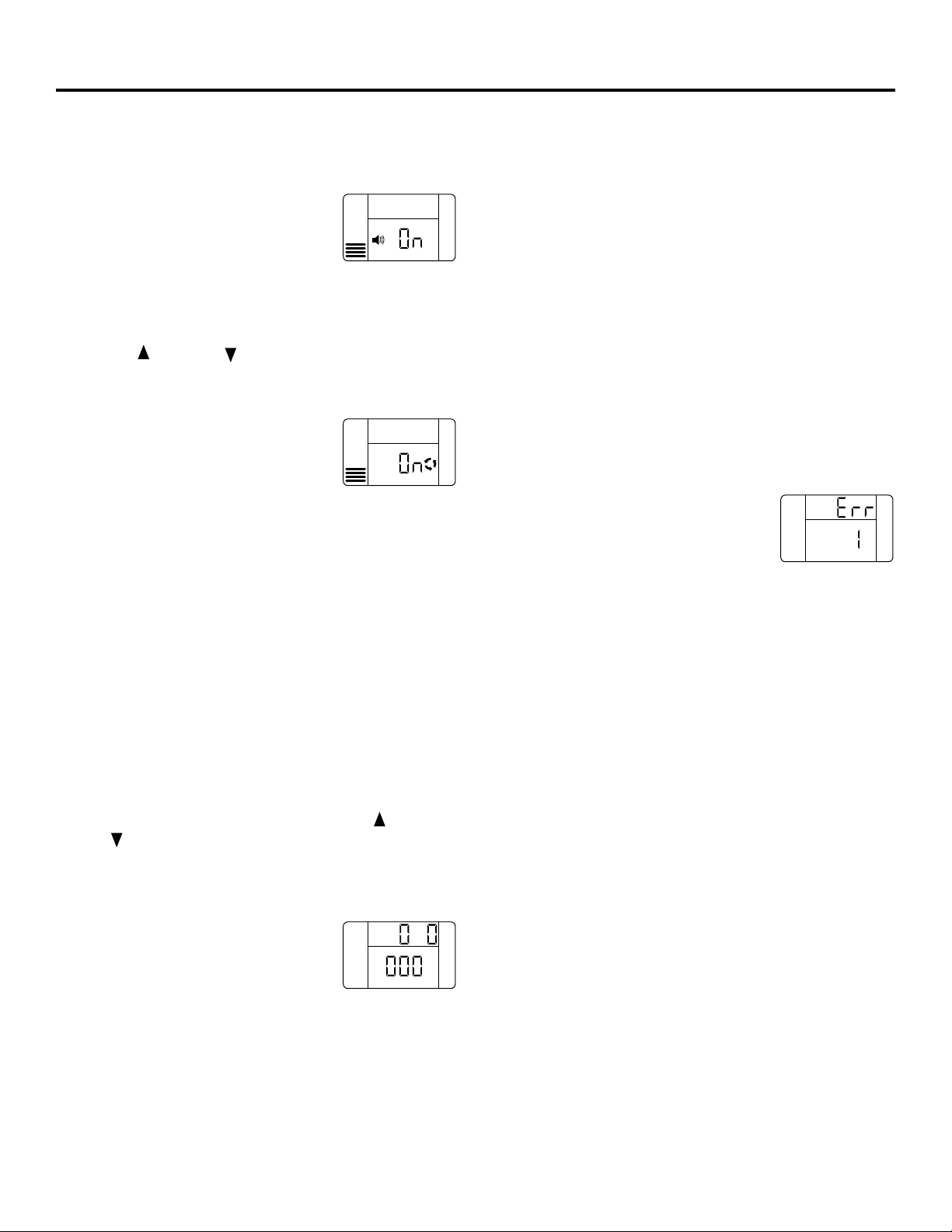
GEAppliances.com
41
Ajustes opcionales de control
La pantalla del controlador ofrece varias opciones y
características.
ALARMA DE BAJO NIVEL DE SAL
La LOW SALT ALARM (alarma de bajo
nivel de sal), cuando está activada, sonará
cuando el valor de DAYS TO EMPTY (días
para desocupar) sea de 15 días o menos. Para cambiar
este nivel, presione y sostenga el botón MODE (modo) por
3 segundos. Por configuración de fábrica, las palabras ON
y OFF aparecen intermitentes en la pantalla. Presione los
botones UP o DOWN para fijar esta función en ON
o en OFF. Presione el botón MODE (modo) para aceptar, y
la pantalla pasa a SALT EFFICIENCY (eficiencia de la sal).
EFICIENCIA DE LA SAL
Cuando la función de SALT EFFICIENCY
(eficiencia de la sal) de la sal esté
encendida (ON), la unidad opera a una
eficiencia de por lo menos 4000 granos de dureza removida
por libra de sal. Este modo de operación es el nivel más eficaz
para el uso de la sal, dado que el sistema tiende a regenerarse
más a menudo, con menos uso de sal. Fijar la función en la
posición de apagado (OFF) tiende a prolongar el tiempo entre
los ciclos de recarga, lo que ofrece el uso más eficiente del
agua, pero puede usar más sal. El grado de diferencia entre
estos dos ciclos depende en gran medida del uso del agua y
de la dureza en una instalación en particular.
Si usted tiene agua muy dura, y se da cuenta de que su
sistema está regenerando cada 1-2 días, fije la posición
de SALT EFFICIENCY (eficiencia de la sal) a la posición de
apagado (OFF) para alargar el tiempo entre regeneraciones.
NOTA: Las regulaciones de California exige que esta función
esté en la posición de encendido (ON) para instalaciones
en California.
Para cambiar este nivel, presione los botones UP o
DOWN para fijar la función en encendido o apagado.
Presione el botón MODE (modo) para aceptar. La pantalla
pasa a SYSTEM/ELECTRONIC DIAGNOSTICS (diagnóstico
electrónico/del sistema).
DIAGNÓSTICO ELECTRÓNICO/DEL SISTEMA
Esta visualización contiene información
sobre el diagnóstico del sistema para
ayudar a la solución de problemas del
sistema. Consulte las páginas 46–49 para detalles. Presione
el botón MODE (modo) para regresar a la visualización de
corrida normal.
SEÑAL DE HORA PERDIDA
Si la hora se pierde en la pantalla debido a una interrupción
en el suministro eléctrico, la luz indicadora azul se enciende
cuatro veces intermitentemente cada segundo, hasta que se
ingrese la hora actual del día.
SEÑAL DE BAJO NIVEL DE SAL
Si la función DAYS TO EMPTY (días para desocupar) está por
debajo de 15, la luz indicadora azul se enciende y la señal
DAYS TO EMPTY (días para desocupar) en la pantalla se enciende
cada segundo y la alarma suena cada 30 segundos (desde las
8:00 AM hasta las 8:00 PM) para avisar al usuario que la unidad
está en un nivel bajo de sal. Tan pronto como se presione
cualquier botón, la alarma deja de sonar. La luz indicadora
azul y el mensaje DAYS TO EMPTY (días para desocupar)
continúan intermitentes. Una vez que se agrega sal al tanque
de salmuera y el nivel de sal se vuelve a configurar, la función
de DAYS TO EMPTY (días para desocupar) se configura también.
SEÑALES DE ERROR
Si se detecta un código de error, la luz
indicadora azul se enciende 4 veces cada
segundo de forma intermitente, la pantalla
muestra Err y la alarma suena cada 30 segundos (desde las
8:00 AM hasta las 8:00 PM) para señalar que el descalcificador
necesita mantenimiento. Es posible apagar la alarma al
presionar cualquier botón, sin embargo, la luz azul indicadora
y la pantalla continúa intermitente.
Consulte la página 47 para información sobre la solución
de averías con los códigos de error. Una vez que corrija el
problema, desconecte por un momento el transformador
del tomacorriente y conéctelo nuevamente. Aparece la
visualización normal. Es posible que el motor opere unos
minutos, hasta que la unidad se vuelva a configurar. Si el
problema no se corrige, el código de error vuelve a aparecer
en 6 minutos.
LUZ INDICADORA AZUL
Una luz azul sólida indica que la unidad está trabajando
correctamente. La luz parpadea cuando la unidad necesita
atención de parte del usuario.
• La luz parpadea y DAYS TO EMPTY (días para desocupar)
parpadea—inspeccione el nivel de sal y agregue según
sea necesario.
• La luz parpadea y Err aparece en la pantalla—hay algún
problema eléctrico en el sistema—ver la página 47.
• La luz también parpadeará cuando la energía eléctrica
a la unidad haya sido interrumpida. Inspeccione los
ajustes en PRESENT TIME (hora actual).
SALT
LEVEL
SALT
LEVEL
SALT
LEVEL
E
SALT
LEVEL
Page 42

Instrucciones de instalación paso por paso.
Procedimientos de desinfección
Para completar la instalación, siga los procedimientos
de desinfección siguientes.
En la fábrica se siguen los cuidados para
mantener el descalcificador de agua limpio y
desinfectado. Los materiales usados para construir
el descalcificador no contaminarán ni infectarán
su suministro de agua ni causarán que se forme
o crezca bacteria. Sin embargo, durante el envío,
el almacenamiento, la instalación y la operación,
algún tipo de bacteria podría penetrar el
descalcificador. Por esta razón, el siguiente
proceso de desinfección se sugiere después
de la instalación.
NOTA: La desinfección es recomendada por la
Asociación de Calidad del Agua.
1. Cerciórese de completar todos los pasos de
instalación, incluyendo la programación
del control.
2. Vacíe aproximadamente 3/4 de onza de cloro
casero sin perfume 5,25 % (Clorox, Linco,
Bo Peep, White Sail, Eagle, etc.) en el depósito
de la salmuera. Consulte la ilustración en la
página 35.
3. IMPORTANTE: Oprima y sostenga oprimido por
3 segundos el botón RECHARGE (recargo)
del plato para comenzar una recarga inmediata.
El indicador de RECHARGE (recargo) aparece 4.
intermitente en la pantalla. El cloro es llevado
hacia y a través del descalcificador de agua.
Esta proceso dura aproximadamente 2 horas.
4. Si, después de la desinfección, el agua de la llave
de la casa tiene un sabor salado o tiene un color
ligero, esto es un preservativo del tanque de
resina. Abra los grifos de agua fría descalcificada
por unos minutos hasta que el agua se aclare.
NOTA: Cuando la recarga de limpieza termine,
todo el cloro restante es purgado de su
acondicionador y el suministro de agua FRÍA de su
casa está completa e inmediatamente descalcificada.
Sin embargo, su calentador de agua está lleno de
agua dura y a medida que el agua caliente se use,
el calentador se llena con agua descalcificada. Cuando
toda el agua dura se reemplace en el calentador
de agua, el agua caliente y el agua mezclada caliente
y fría, estarán completamente descalcificadas.
Si desea agua descalcificada inmediatamente,
después de la recarga anterior, drene agua
del calentador hasta que el agua salga fría.
ADVERTENCIA:Si usted drena
el calentador de agua, tenga cuidado extremo,
ya que el agua caliente lo podría quemar. Apague
el calentador de agua antes de proceder con
el drenaje.
Especificaciones/Dimensiones
33⁄8″
(8,7 cm)
Salida
ENTRADA–SALIDA
16″
19″
Estos sistemas se conforman a NSF/ANSI 44 para los reclamos de capacidad específica verificados y substanciados por datos de prueba.
* La prueba se llevó a cabo usando bolitas grado cloro de sodio como sal regeneradora.
** El ritmo de eficiencia es válido solamente ante la dosis de sal más baja. La eficiencia de estos descalcificadores fue evaluada de
acuerdo con NSF/ANSI 44.
*** La cantidad de hierro removido puede variar según las condiciones. La capacidad para reducir el hierro de agua clara es
sustentada por los datos de las pruebas WQA. El estado de Wisconsin requiere tratamiento adicional si el suministro de agua
contiene más de 5 ppm de hierro de agua clara. Use Diamond Crystal®Red•Out®o Super Iron Out®, lo que mejora la eliminación
del hierro. Consulte la sección Limpieza del hierro del agua del sistema de descalcificación.
**** Limites de presión de trabajo en Canadá: 1,4–7,0 kg/cm2.
GXSF35E GXSF39E
Ritmo de capacidad* 14000 granos con 15300 granos con
2,8 lbs. de sal 3,0 lbs. de sal
29600 granos con 32800 granos con
8,8 lbs. de sal 9,6 lbs. de sal
35200 granos con 39100 granos con
14,7 lbs. de sal 16,1 lbs. de sal
Ritmo de eficiencia** 5000 granos/lb. 5100 granos/lb.
@ 2,8 lbs. de sal @ 3,0 lbs. de sal
Cantidad de capacidad de resina alta (lbs/cu. pies) 47,8/0,92 52,5/1,01
Tamaño nominal del tanque de resina
(pulg., diam. x altura) 9 x 40 9 x 40
Ritmo de flujo de servicio (gpm) 8,5 8,0
Dureza máxima del suministro de agua (gpg) 100 110
Hierro de agua clara máximo en el agua de
suministro (ppm)*** 6 8
Límites de presión de agua (mín.–máx. psi)**** 20–125 20–125
Caída de presión al ritmo de flujo de servicio (psig) 15 15
Temperatura máxima del agua (mín.–máx. °F) 40–120 40–120
Ritmo de flujo máximo para drenaje (gpm) 2,0 2,0
Entrada
471⁄2″
(120,7 cm)
411⁄4″
(104,8 cm)
(40,6 cm)
(48,3 cm)
42
Page 43

43
Sobre el sistema de descalcificación de agua.
GEAppliances.com
Servicio
Cuando el sistema descalcificador de agua está
proporcionando agua descalcificada, a esto se le
llama “Servicio”. Durante el servicio, el agua dura
fluye desde la tubería de agua principal de la
casa hacia el sistema de descalcificación de agua.
En el interior del tanque de resina del sistema de
descalcificación de agua hay una película o capa
compuesta de miles de resinas plásticas diminutas.
Cuando el agua dura pasa a través de la capa, cada
resina diminuta atrapa los minerales duros. A esto
se le llama intercambio de iones. Es como un
imán que atrae y atrapa metales. Luego, el agua
sin minerales duros (agua descalcificada o agua
blanda) fluye hacia la casa desde el sistema de
descalcificación.
Después de un período de tiempo, la capa de
resina se obstruye o se satura con los minerales
duros y debe limpiarse. Esta limpieza se denomina
recarga. La recarga comienza a las 2:00 AM
(ajustado en fábrica) por el control del sistema
de descalcificación de agua, y consiste en cinco
etapas o ciclos. Éstas son FILL (llenado), BRINING
(proceso de salado), BRINE RINSE (enjuague salado),
BACKWASH (lavado regresivo) y FAST RINSE
(enjuague rápido).
En casos de emergencia, el agua dura está
disponible hacia la casa durante los ciclos
de recarga.
Sin embargo, usted debe evitar usar agua CALIENTE
porque el calentador de agua se llenará con
agua dura.
Circunvalación automática del agua dura durante la recarga
Llenado
La sal disuelta en agua es llamada salmuera. La
salmuera es necesaria para limpiar los minerales
duros de las diminutas partículas de resina. Para
formar la salmuera, el agua fluye hacia el interior
del tanque de sal durante el período de llenado.
Salado
Durante el proceso de salado, la salmuera se
desplaza del área del tanque de almacenamiento
de la sal hacia el tanque de la resina. La salmuera
es el agente de limpieza necesario para remover
los minerales duros de la capa de resina. Los
minerales duros y la salmuera son descargados
hacia el desagüe.
La boquilla y el Venturi crean una succión para
mover la salmuera, manteniendo un ritmo muy
bajo para obtener la resina de limpieza con la
menor cantidad de sal.
Enjuague Salado
Después de que se use una cantidad de salmuera
medida con anterioridad, la válvula de salmuera
se cierra. El agua continúa fluyendo en la misma
trayectoria que durante el proceso de salado,
excepto por el flujo de salmuera discontinuado.
Los minerales duros y la salmuera fluyen del
tanque de resina hacia el desagüe.
Lavado Regresivo
Durante el lavado regresivo, el agua viaja hacia
arriba a través del tanque de resina a un flujo de
ritmo rápido, purgando el hierro acumulado, la
suciedad y los sedimentos desde la capa de resina
hacia el desagüe.
Enjuague Rápido
El lavado regresivo es seguido por un flujo de
agua rápido hacia abajo a través del tanque de
resina. El flujo rápido purga la salmuera del fondo
del tanque, y rellena el tanque de resina.
A continuación del enjuague rápido, el sistema de
descalcificación de agua regresa al servicio de agua
descalcificada.
Page 44

44
Sobre el sistema de descalcificación de agua.
Cómo romper un puente de sal
A veces, una capa dura de sal o puente de sal se
forma en el área de almacenamiento de la sal.
Esto generalmente se debe a la humedad alta o
al uso de algún tipo de sal equivocada. Cuando
la sal forma puente, un espacio vacío se forma
entre el agua y la sal. Entonces la sal no se
disuelve en el agua para hacer la salmuera.
Si el tanque de la sal está lleno de sal, es difícil
saber si existe o no un puente de sal. La sal está
floja en la parte superior, pero el puente está
por debajo. A continuación, la forma más
efectiva de inspeccionar si existe la formación
de un puente de sal.
La sal debe estar floja desde arriba hasta el
fondo del tanque. Tome un palo de escoba o
algo parecido, y con cuidado, empújelo hacia
el interior del depósito de sal, introduciéndolo
y sacándolo. Si el instrumento golpea un objeto
duro (cerciórese de que lo que golpea no es
el fondo o las paredes laterales del tanque),
es posible que exista un puente de sal. Con
cuidado, rompa el puente con el instrumento.
No golpee las paredes del tanque.
Si el tipo de sal equivocada es usado para
hacer la salmuera, sáquela. Entonces llene el
tanque con sal de pepitas o bolitas solamente.
En áreas húmedas, es mejor llenar el depósito
con menos sal, y hacerlo más a menudo para
evitar la formación de puentes de sal.
Empuje el instrumento hacia
el interior del depósito de sal
para romper el puente
Marca
de lápiz
Instrumento
Sal
Puente
de sal
Nivel de agua
1″–2″
(2,54 cm–5,1 cm)
Page 45

45
Es necesario que la boquilla y el Venturi estén
limpios para que el sistema de descalcificación
de agua funcione apropiadamente. Esta pequeña
unidad ejecuta la succión para mover la
salmuera del área de almacenamiento de sal
hacia el tanque de resina durante la recarga.
Si está atascada con arena, sucia, etc., el sistema
de descalcificación de agua no funcionará y
usted solamente tendrá agua dura.
Para lograr acceso a la boquilla y al Venturi,
retire la tapa superior del sistema de
descalcificación de agua. Cerciórese de que
el sistema de descalcificación de agua está en
ciclo de servicio (que no haya presión de agua
en la boquilla y el Venturi). Luego, mientras
sostiene el alojamiento de la boquilla y el
Venturi, remueva la tapa. Levante el soporte del
filtro y el filtro, luego la boquilla y el Venturi.
Lave y enjuague las partes en agua cálida hasta
que estén limpios. Si es necesario, use un cepillo
pequeño para remover el hierro o la suciedad.
También inspeccione y limpie la junta.
NOTA: Algunos modelos tienen un pequeño
tapón de flujo localizado en la boquilla y
el Venturi, y/o un pequeño filtro en forma
de cono en el alojamiento. Cerciórese de
inspeccionar y limpiar estas partes, si su
modelo está equipado con ellos.
Con cuidado reemplace todas las partes en
el orden correcto. Lubrique ligeramente el
sello del aro tórico con una grasa de silicona
o con vaselina y coloque en su posición.
Instale y apriete la tapa con sus manos solamente.
No apriete la tapa demasiado.
Cómo limpiar la ensambladura de la boquilla y el Venturi
IMPORTANTE: Cerciórese de que los agujeros pequeños en
la junta estén centrados directamente sobre los pequeños
agujeros en el alojamiento de la boquilla y el Venturi.
*Instale con el lado que contiene números hacia arriba y
el lado cóncavo hacia abajo.
Tapa
Sello del aro
tórico
Soporte del
filtro
Filtro
Filtro
Boquilla y Venturi
Alojamiento de la
boquilla y el Venturi
Junta
*Tapón de flujo
*Tapón de flujo
GEAppliances.com
Page 46

46
Durante la operación normal, la hora actual
del día y AM o PM y DAYS TO EMPTY (días
hasta desocupar) se muestran en el área de la
pantalla de control. Cuando la computadora
de demanda determina que una recarga es
necesaria, el mensaje RECHARGE TONIGHT
(recargue esta noche) comienza a parpadear
en la pantalla con la hora actual. RECHARGE
TONIGHT (recargue esta noche) parpadea hasta
el momento de inicio de la próxima recarga,
cuando cambiará a RECHARGE (recargo), el cual
parpadea hasta que la recarga concluya.
Operación normal, Pantalla de control
A veces, es posible que usted desee o
necesite una recarga iniciada manualmente.
Dos ejemplos:
■ Usted ha usado más agua que de costumbre
(huéspedes en la casa, lavado adicional, etc.)
y quizás se quede sin agua descalcificada
antes de la próxima recarga.
■ Se le acabó la sal al sistema.
Use una de las funciones siguientes para
comenzar una recarga inmediatamente,
o en el próximo inicio de recarga
preprogramada.
RECARGUE ESTA NOCHE
Oprima (no sostenga oprimido) el botón de
RECHARGE (recargo) . RECHARGE TONIGHT
(recargue esta noche) comienza a parpadear
en el área de la pantalla de control. Una
recarga ocurrirá en el próximo inicio
de recarga preprogramada. Si decide cancelar
esta recarga, toque el mismo botón una vez más.
RECARGO
Oprima y sostenga oprimido el botón de
RECHARGE (recargo) hasta que RECHARGE
(recargo) comience a parpadear en la pantalla
de control. El sistema de descalcificación de
agua comienza una recarga inmediata y,
cuando termine en unas dos horas, usted
tendrá un nuevo suministro de agua
descalcificada. Una vez haya iniciado,
usted no puede cancelar la recarga.
Función: Controles opcionales de recargado
Función: Memoria
Si el suministro eléctrico del sistema de
descalcificación de agua es interrumpido, la
pantalla de control estará en blanco, y la luz
indicadora azul se apaga, pero el control
mantiene la hora correcta por seis horas
aproximadamente. Cuando el suministro es
restaurado, usted tendrá que reajustar la hora
actual solamente si la visualización y la luz
indicadora azul están intermitentes. Todos los
otros ajustes se mantienen y nunca requieren
ser ajustados a no ser que usted desee hacer
algún cambio.
Si la hora está intermitente después de una
interrupción prolongada en el suministro
eléctrico, el sistema de descalcificación de
agua continúa operando como debería para
proporcionarle agua descalcificada. Sin
embargo, la recarga podrían ocurrir a la
hora equivocada del día hasta que usted
reajuste el control a la hora correcta del día.
Sobre el sistema de descalcificación de agua.
La computadora de control tiene una función
de diagnóstico automático para el sistema
eléctrico (excepto para la energía de entrada
y la medición del agua). La computadora
monitorea los componentes electrónicos y los
circuitos para una operación correcta. Si ocurre
un error, un código de error aparece en la
pantalla de control.
La tabla de Códigos de Errores (Error Codes)
muestra los códigos de errores que podrían
aparecer y las razones posibles para cada
código. Ver Cómo iniciar el diagnóstico
electrónico manualmente para aislar el defecto
aún más.
Característica/Servicio: Diagnosis electrónica automática
Page 47

47
Para eliminar un código de error: 1. Desconecte el transformador.
2. Corrija el problema.
3. Conecte otra vez el transformador.
4. Espere por lo menos 6 minutos. El código de error regresará si la razón
del código de error no ha sido corregida.
NO HAY AGUA
DESCALCIFICADA
EL CONTROL MUESTRA LA
HORA Y EL DÍA EQUIVOCADOS,
Y/O ESTÁ INTERMITENTE.
LA PANTALLA
DE CONTROL
ESTÁ EN
BLANCO.
LA PANTALLA DE CONTROL
MUESTRA LA HORA
CORRECTA Y EL DÍA Y NO
ESTÁ INTERMITENTE.
Inspeccione la energía
eléctrica hacia el control
(interruptor, transformador,
cable eléctrico y todas las
conexiones).
Realice
diagnóstico
manual.
SIN SUMINISTRO
SUMINISTRO OK
REPARE SEGÚN
SEA NECESARIO
CONTROL
DEFECTUOSO
Lleve a cabo los
diagnósticos manuales
para verificar que todo
funciona correctamente.
El suministro eléctrico ha
sido interrumpido. Reajuste
la hora correcta del día.
GEAppliances.com
Servicio: Funciones y servicio del tiempo de demanda electrónico
Si usted no está recibiendo agua descalcificada,
y no aparece un código de error, use el
siguiente procedimiento para encontrar la
fuente del problema. Primero realice las
siguientes inspecciones visuales.
INSPECCIONES VISUALES:
1. ¿Hay energía eléctrica entrando hacia el
tomacorriente en el cual el transformador
del sistema de descalcificación de agua está
conectado?
2. ¿Hay suficiente sal en el tanque de
almacenamiento?
3. ¿Está la válvula de bypass de descalcificación
dirigiendo el agua para el servicio de
descalcificación?
4. ¿Está la manguera de drenaje de la válvula
abierta hacia el drenaje, a no más de 8 pies
(2,67 m) por arriba del descalcificador, y no
tiene ninguna obstrucción? Si la manguera
está más de 8 pies (2,67 m) por arriba del
descalcificador, ver la página 37, sección 4.
Si usted no encuentra el problema con la
inspección visual, continúe más adelante.
Servicio: Sincronizador/Descalcificador, procedimiento de inspección del servicio
CÓDIGO DE ERROR
VISUALIZADO ERR 01 ERR 02 ERR 03 ERR 04 ERR 05
POSIBLE DEFECTO • El motor no • Interruptor • Motor no • Interruptor • Control
funciona de posición funciona o de posición o
problemas en problemas en
el cableado el cableado
• Problemas en • Control • Control • Control
el cableado o
en la conexión
hacia el
interruptor
• Interruptor
de posición
• Control
Investigue la razón de la
interrupción eléctrica.
Page 48

48
Sobre el sistema de descalcificación de agua.
1. Para entrar a la función de diagnóstico,
oprima y mantenga oprimido el botón
MODE (modo) por tres segundos hasta
que aparezca la pantalla de LOW SALT
ALARM (alarma de bajo nivel de sal).
2. Presione el botón MODE (modo) 2 veces
para avanzar a las opciones LOW SALT
ALARM (alarma de bajo nivel de sal) y
SALT EFFICIENCY (eficiencia de la sal).
Vea la sección Programación del control
para detalles sobre estas dos opciones.
3. OPERACIÓN DE DIAGNÓSTICO
• Posición de la válvula—Presione el botón RECHARGE
(recargo) para iniciar un ciclo de recarga. Presione
de nuevo para llevar la válvula manualmente a la
siguiente posición. Consulte la sección Servicio: Revisión
de recarga con avance manual para detalles.
0 – Servicio
1 – Llenado
2 – Proceso de salado
3 – Lavado regresivo
4 – Enjuague rápido
• Operación del motor—Dos rayas circulan alrededor
cuando el motor debería estar operando.
• Operación del interruptor de posición—
– Cerrado—la válvula rota hacia la siguiente
posición
– Abierto—la válvula está en posición, servicio,
llenado, salado, etc.
• Medidor del agua—Indica si el agua fluye a través
de la válvula.
– 000 indica que no hay agua fluyendo hacia la válvula
– Abrir un grifo cercano de agua descalcificada
– 000 hasta 199 (continuo) muestra que el agua fluye.
La visualización se repite por cada galón de agua que
pasar por el medidor. El control produce un sonido
por cada galón.
– Si no hay lectura en la pantalla, con el grifo abierto,
revise el sensor. Hale el sensor del puerto de salida
de la válvula, y pase un pequeño imán por el frente
del sensor. El contador debe aparecer en la pantalla.
Si el contador no aparece, revise para cerciorarse de
que los cables están conectados correctamente al
tablero. Si hay una lectura en la pantalla, puede
haber un problema relacionado con la turbina.
Cierre el suministro del agua, cierre la válvula de
bypass, y desconecte la válvula de bypass del cuerpo
de la válvula. Revise la turbina en busca de ataduras
o restricciones por causa de restos. Si esto no corrige
el problema, es posible que deba reemplazar el
sincronizador, el sensor o la turbina.
4. Hay datos históricos disponibles sobre el descalcificador.
• Presione y mantenga presionado el botón UP para
visualizar el número de días que este control ha estado
con corriente eléctrica.
• Presione y sostenga el botón DOWN para visualizar
el número des recargas iniciadas por este control desde
que se ingresó el número del código del modelo.
5. Presione el botón MODE (modo) para regresar a la
operación normal y visualización.
Servicio: Diagnóstico electrónico iniciado manualmente
Medidor del agua
Posición de
la válvula
Interruptor
de posición
Motor
Motor
Turbina
Soporte de la
turbina y eje
Alojamiento
del sensor
Interruptor
de posición
Salida de
la válvula
SALT
LEVEL
SALT
LEVEL
SALT
LEVEL
Page 49

49
GEAppliances.com
1. Para cambiar o revisar el código del modelo,
presione primero y sostenga el botón MODE
(modo) por tres segundos hasta que aparezca
la pantalla de la LOW SALT ALARM (alarma de
bajo nivel de sal).
2. Presione y sostenga
el botón MODE (modo)
nuevamente por tres
segundos. En la parte
superior de la pantalla
aparece la palabra .
3. Presione los botones UP o DOWN
para seleccionar el código de modelo
correcto.
SR22–GXSF27E, F31–GXSF31E,
F35–GXSF35E, F39–GXSF39E,
H39–GXSH39E, H45–GNSH45E
4. Presione el botón MODE (modo) una vez
para regresar a la operación y visualización
normal. Si el código del modelo cambió:
• la pantalla se pondrá en blanco
momentáneamente, luego se visualiza
el código de modelo ingresado.
• la pantalla regresa a la visualización de
la hora actual y la luz indicadora azul se
prenderá de forma intermitente. Es
necesario reprogramar el control. Consulte
la sección Reprogramación del control.
NOTA: Si el control es dejado en una visualización
de diagnóstico o en una pantalla intermitente
cuando se ajusta la hora o la dureza, la hora
actual regresa automáticamente si un botón no
es oprimido dentro de cuatro minutos.
NOTA: La pantalla de control debe mostrar la
hora de manera estable (no intermitente).
1. Presione el botón RECHARGE (recargo)
y sosténgalo presionado por tres segundos.
La palabra RECHARGE (recargo) comienza
a parpadear a medida que el sistema de
descalcificación de agua inicia el ciclo
llenado de recarga. Retire la cubierta del
depósito de la salmuera y, con una linterna,
observe el agua de llenado entrando hacia el
tanque de salmuera. Si no hay agua entrando
al tanque, busque cualquier obstrucción en
una boquilla, el Venturi, el tapón de flujo de
llenado o la tubería de la salmuera. Consulte
la sección Cuidado y limpieza del sistema de
descalcificación de agua.
2. Después de observar el llenado, presione el
botón RECHARGE (recargo) para llevar al
sistema de descalcificación de agua al
proceso de salado. Un flujo lento de agua
hacia el drenaje debe comenzar. Verifique
la extracción de la salmuera del tanque
alumbrando con una linterna hacia el
depósito de la salmuera y observando un
goteo evidente en el nivel de líquido
durante un período de tiempo extenso.
NOTA: Cerciórese de que no es un puente
de sal el que está evitando el contacto con
la sal. Consulte la sección Cuidado y limpieza
del sistema de descalcificación de agua.
Si el sistema de descalcificación de agua no
extrae salmuera, inspeccione:
■ Que la boquilla y/o el Venturi no estén
sucios o defectuosos.
■ Que el empaque de la boquilla o el
Venturi no estén defectuosos.
■ Que la boquilla y/o el Venturi no estén
bien asentados en la junta.
■ Otro defecto de la válvula interna
(empaque del rotor, rotor y disco,
arandela de onda, etc.).
■ Que no exista un drenaje restringido
(inspeccione los accesorios del drenaje y
la manguera).
NOTA: Si la presión del sistema de agua es baja,
una manguera elevada podría causar presión
regresiva, evitando la extracción de la salmuera.
3. De nuevo, presione el botón RECHARGE
(recargo) para llevar el sistema de
descalcificación de agua al lavado regresivo.
Busque un flujo rápido de agua de la
manguera de drenaje. Un flujo lento indica
que se ha obstruido un distribuidor superior,
un tapón de flujo de lavado regresivo o la
manguera de drenaje.
4. Presione el botón RECHARGE (recargo)
para llevar el sistema de descalcificación de
agua al enjuague rápido. De nuevo, busque
un flujo rápido. Permita que el sistema de
descalcificación de agua enjuague por unos
minutos para purgar cualquier salmuera que
haya quedado en el tanque de resina durante
la prueba del ciclo del proceso de salado.
5. Para regresar el sistema de descalcificación
de agua a servicio, presione el botón
RECHARGE (recargo) .
Servicio: Inspección manual del avance de la recarga
Servicio: Configurar el código del modelo (F o H)
SALT
LEVEL
Page 50

50
Cuidado y limpieza del sistema de descalcificación de agua.
Se necesita salmuera (sal disuelta en agua)
para cada recarga. El agua para hacer la
salmuera es medida cuando entra al área de
almacenamiento de la sal a través de la válvula
del sistema de descalcificación de agua y el
control. Sin embargo, usted debe mantener el
tanque con sal.
Cuándo rellenar con sal: si una luz indicadora
azul se enciende y muestra DAYS TO EMPTY
(días hasta desocupar) parpadeando, hay menos
de 15 días de suministro de sal. Rellene con sal.
En áreas húmedas es mejor llenar con menos
sal y hacerlo más frecuentemente, para evitar
la formación de puentes de sal, consulte la
página 44. Después de agregar sal, recuerde
restablecer el SALT LEVEL (nivel de sal) en el
control, consulte la página 40. Nunca permita
que el nivel de sal dejar caer bajo cero en la
indicadora amarilla antes de usted rellenarlo.
Sin suficiente sal, pronto tendrá agua dura.
Utilice sales de sistemas de descalcificación de
agua solamente, por lo menos 99,5% puras.
Recomendamos PEPITAS, BOLITAS o SAL
GRUESA SOLAR. No use sal en roca, en bloques,
granulada ni de helado (para descongelar hielo).
Éstas contienen suciedad y sedimentos, o pasta
y masa, y crearán problemas de mantenimiento.
PRECAUCIÓN:
Sal descalcificadora de agua con aditivos que
remueven el hierro: Algunas sales podrían
tener aditivos para ayudar al sistema de
descalcificación de agua con el hierro en
el suministro de agua. Aunque este aditivo
puede ayudar a mantener limpio el sistema
de descalcificación de agua, el mismo
también puede crear gases corrosivos que
debilitan y acortan la vida de las partes
del sistema de descalcificación de agua.
GE solamente recomienda el uso de la
marca de sal Diamond Crystal®Red•Out®.
Inspeccione el nivel de almacenamiento de la sal y el rellenado
Su sistema de descalcificación de agua toma la
dureza de los materiales (calcio y magnesio) y
la extrae del agua. También, puede controlar
una cantidad considerable del hierro del
“agua clara” (Consulte la sección Directrices de
especificaciones). Con hierro de agua clara, el
agua de un grifo es clara cuando se coloca en
un vaso al principio. De 15 a 30 minutos más
tarde, el agua comienza a ponerse turbia o a
cambiar a un color rojo ladrillo. Un sistema de
descalcificación de agua no remueve el hierro
que causa que el agua se torne turbia o que
adquiera el color rojo ladrillo cuando sale del
grifo (llamada agua rojo ladrillo). Para extraer
el hierro de esta agua se requiere un filtro u
otro equipo.
GE recomienda que se usen las marcas de sal
Diamond Crystal®Red•Out®con aditivo Iron
Fighter®para ayudar a mantener la capa de
resina limpia del hierro. Si su suministro de
agua tiene hierro de agua clara, es necesario
que usted limpie periódicamente la capa de
resina. GE recomienda usar un limpiador de
capas de resina Super Iron Out®, para limpiar
así eficientemente dicha capa, especialmente
cuando el contenido de hierro es alto. Limpie
la capa por lo menos cada seis meses, o más a
menudo si comienza a aparecer hierro en su
agua descalcificada entre limpieza y limpieza.
IMPORTANTE: Es importante mezclar el
limpiador de la capa de resina con agua
(siga las instrucciones del fabricante) y vaciarlo
en el depósito de la salmuera (ver página 35)
y proceda a regenerar el descalcificador
inmediatamente. No vierta el limpiador de la
capa de resina con la sal, ya que no será tan
eficiente en su función de limpieza de la resina,
y puede causar daños al descalcificador si se
deja en el tanque de la sal por un período de
tiempo prolongado debido a que gases
corrosivos se formarían.
Cómo limpiar el hierro de su sistema de descalcificación de agua
Page 51

51
Consejos para la identificación y solución de averías
¡Ahorre tiempo y dinero! Revise las tablas en las siguientes páginas primero
y quizás no tenga que llamar para solicitar servicio.
Problema Posible causa Qué hacer
No hay agua El grifo o el accesorio donde la •
Para conservar sal, el instalador puede que haya aislado
descalcificada muestra
fue tomada no está conectado
algunos grifos (grifos fuera de la casa, inodoros, etc.)
al sistema de agua descalcificada
del sistema de descalcificación. A partir de la salida del
NOTA: Cerciórese de que la muestra no sistema de descalcificación de agua, rastree la trayectoria
es tomada de un grifo que mezcla agua de la tubería de la casa. Si el agua descalcificada no está
descalcificada con agua dura. Por ejemplo, conecada directamente a un grifo o accesorio donde a
un grifo de una sola palanca de la cocina, usted le gustaría que estuviera conectado, póngase en
si la tubería del agua fría de ese grifo está contacto con un plomero.
conectada al agua dura.
No hay sal en el tanque de la • Revise si hay un puente de sal, o si el tanque está vacío,
salmuera o hay un puente de sal llene otra vez con la sal recomendada. Presione (por tres
segundos) el botón RECHARGE (recargo) para dar inicio
a la recarga y restaurar el suministro de agua descalcificada.
El transformador está desconectado
• Inspeccione para cerciórese de que no ha habido una
en el
tomacorriente de la pared, o el interrupción energética hacia el descalcificador de agua
cable del descalcificador no está debido a algunas de estas condiciones y corrija según sea
conectado. Un fusible está fundido o se necesario. Una vez restaurada la energía, observe la
desconectó en el circuito eléctrico hacia visualización en el plato y lea la sección Programación
el tomacorriente. El tomacorriente del
control. NOTA: El tomacorriente para el interruptor del
está en un circuito que no puede ser
descalcificador debe estar permanentemente conectado para
desconectado
que no pueda ser desconectado accidentalmente.
La válvula de bypass manual está • Cerciórese de que la palanca de la válvula de bypass se
en la posición de bypass
encuentre en la posición correcta, con el botón en la posición
OUT (afuera). Observe las instrucciones en la etiqueta
en el extremo de la palanca.
La manguera de drenaje de la válvula •
Cualquier restricción en esta manguera de drenaje puede
está atascada, obstruida, elevada a una
prevenir
la
operación apropiada de la boquilla y el Venturi y
posición demasiado alta u obstruida reducir o evitar la toma de la salmuera durante la recarga.
de alguna forma
NO HAY AGUA DESCALCIFICADA—Problemas más comunes:
Inspeccione lo siguiente antes de llamar para solicitar servicio:
• No hay suficiente sal—debe estar por lo menos lleno hasta 1/3.
• La válvula de bypass está en la posición de “Bypass”—el indicador debe estar en la
posición “OUT” (servicio).
• El ajuste de dureza es demasiado bajo—inspeccione el ajuste de la dureza y ajústelo.
Verifique la dureza del suministro de agua—llamando a su compañía de agua local,
haciendo pruebas al agua o llamando al Centro de Respuestas de GE.
• Puente de sal—la sal se solidifica por encima del nivel del agua de forma tal que la
salmuera no está en contacto con la sal. Ver la sección Cómo romper un puente de sal.
Antes de llamar para solicitar servicio…
GEAppliances.com
Page 52

52
Antes de llamar para solicitar servicio…
el sistema de
descalcificación de
agua fue instalado
Problema Posible causa Qué hacer
No hay agua La boquilla y el Venturi están sucios, • Consulte las instrucciones para Limpiar la boquilla y el Venturi.
descalcificada (cont.) ensamblados incorrectamente Con la
presión del agua desconectada del sistema de
o dañados
descalcificación de
agua, desarme la ensambladura de la
boquilla. Inspecciónela, límpiela y reemplace cualquier
parte según sea necesario. Cualquier partícula extraña,
ralladura, muesca, etc., en los pasajes puede
impedir la
operación. Cerciórese de que los agujeros en la
junta estén
centrados directamente sobre los agujeros en el alojamiento.
A veces el agua Usar agua caliente mientras el • Evite usar agua caliente mientras el descalcificador de agua
está dura descalcificador de agua está en está en el proceso de recarga porque el calentador de agua
el proceso de regeneración se rellenará con agua dura. Consulte la sección Circunvalación
del agua dura automática durante la recarga, página 43.
El nivel de HARDNESS (dureza) • Presione el botón MODE (modo) hasta que la flecha señale
del control es muy bajo HARDNESS (dureza). Cerciórese de que el número que
aparece es igual que el número real de granos por galón,
la dureza de su suministro de agua. Consulte la sección
Programación del control si se necesita un cambio en los
niveles.
Los granos de dureza en su •
La dureza del agua puede cambiar con el paso del tiempo,
suministro de agua han especialmente cuando se trata de agua de pozo. Para
aumentado inspeccionar, hágale una prueba al agua en un laboratorio de
análisis o llame a su compañía local de suministro de agua.
Ajuste el valor de la HARDNESS (dureza) según sea necesario.
El agua se siente Ausencia de minerales de dureza • Esto es normal. La dureza le da la sensación abrasiva al agua
resbalosa después de la a la que usted está acostumbrado. Esta sensación de que el
instalación del sistema de agua resbalosa es porque ahora ha sido descalificada.
descalcificación de agua
El sistema de El sistema de descalcificación • No usa tanta sal para regenerarse, es muy eficiente.
descalcificación de de agua es una unidad de
agua no está usando “demanda”
ninguna sal
Posible puente de sal • Consulte la sección Sobre el sistema de descalcificación de
agua, en la página 44.
La boquilla o el Venturi • Consulte la sección Sobre el sistema de descalcificación de
posiblemente obstruidos agua, en la página 45.
El agua tiene un color Agua ácida en tuberías de cobre • Inmediatamente solicite que se le haga una prueba al agua.
azul después de que
Page 53

53
GEAppliances.com
Problema Posible causa Qué hacer
El sistema de La turbina del medidor está atascada • Consulte la sección Servicio: Diagnóstico electrónico iniciado
descalcificación no manualmente, para procedimientos de solución de averías,
está regenerando en la página 48.
• Llame y solicite servicio.
Alambre del sensor no conectado • Consulte la sección Servicio: Diagnóstico electrónico iniciado
en el control manualmente, para procedimientos de solución de averías,
en la página 48.
• Llame y solicite servicio.
No hay energía eléctrica en la unidad • Inspeccione el interruptor de circuito o los fusibles.
Defecto mecánico • Llame y solicite servicio.
Agua turbia en la Combinación de agua descalcificada • A esto se le llama grabado de aguafuerte y es permanente.
cristalería (en los y demasiado detergente Para evitar que esto suceda, use menos detergente si usted
lavaplatos automáticos) tiene agua descalcificada. Lave la cristalería en el ciclo más
corto que los pueda limpiar.
Nivel alto/excesivo La manguera de drenaje de la válvula • Cualquier restricción en la manguera de drenaje podría
de agua en el tanque está doblada y eso la está obstruyendo, evitar la operación apropiada de la boquilla y el Venturi y
de la salmuera o está demasiado elevada, o su flujo reduce o evita que se descargue la salmuera durante la
está obstruido de alguna otra forma recarga.
La boquilla o el Venturi están sucios, • Ver la sección de Cómo limpiar la ensambladura de la boquilla y
ensamblados incorrectamente el Venturi en la página 45. Con presión de agua suspendida
o dañados hacia el sistema de descalcificación, desarme la
ensambladura. Inspecciónela, límpiela y reemplace las
partes que puedan estar dañadas. Cualquier partícula
extraña, rasgaduras, picaduras, etc. en la vía podría evitar
la operación correcta. Cerciórese de que los agujeros en la
junta estén centrados sobre los agujeros en el alojamiento.
El agua sabe a sal o tiene La unidad no está limpia • Complete los Procedimientos de desinfección, de la página 42.
aspecto café o amarillo
• Después de que el ciclo de recarga haya sido completado
después de la instalación
(aproximadamente 2 horas), haga circular agua a través de
los grifos para purgar el agua salada.
Baja presión del agua Inspeccione la presión.
• Para altura del drenaje de 8′ o menor, la presión debería ser
de un mínimo de 20 psi.
• Para altura de drenaje superior de 8′, la presión debería ser
de un mínimo de 50 psi.
Manguera de drenaje restringida • Limpie y reconecte la manguera.
• Revise en busca de giros en la línea de drenaje.
Page 54

54
Problema Posible causa Qué hacer
Agua de color La unidad estuvo inoperante • Complete los Procedimientos de desinfección, de la página 42.
café/amarillo por un periodo de tiempo
Las partículas de Distribuidor agrietado • Llame para solicitar servicio.
resina aparecen en
el agua potable y
en los lavamanos
Un sonido que usted Agua circulando desde la unidad • Esto es normal.
puede escuchar hacia el drenaje durante la recarga
El agua tiene burbujas Se introdujo aire en el sistema • Esto desaparecerá después de haber funcionado un tiempo.
de agua y está turbia después de la instalación
Un error de código El cableado podría haberse • Consulte la página 47 para detalles.
en el control aflojado en el control
• Desconecte el transformador.
• Remueva la tapa del control, libere los clips en los costados.
• Inspeccione en búsqueda de conexiones sueltas/incorrectas
de cables hacia el tablero electrónico o interruptor. Vuelva a
conectar según sea necesario.
• Reensamble la tapa del control.
• Conecte el transformador.
• Espere seis minutos para que el error de código reaparezca.
• Si el error de código reaparece, llame para solicitar servicio.
Luz intermitente azul
Al conectar el sistema Se debe programar el control • Consulte la sección Programación del control, en la
(una interrupción el suministro páginas 39–40.
eléctrico podría haber ocurrido)
Si el mensaje Bajo nivel de sal, menos de 15 días • Llene con sal.
•Vuelva a establecer el nivel de sal.
Si la pantalla muestra Problema eléctrico con el sistema • Consulte la página 47 para detalles.
el mensaje “Err”
• Consulte el procedimiento anterior. Código de error en
el control.
Antes de llamar para solicitar servicio…
“DAYS TO EMPTY”
(días para desocupar)
está intermitente
Page 55

55
Notas.
GEAppliances.com
Page 56

56
Lista de partes.
Page 57

57
GEAppliances.com
Page 58

58
CATÁLOGO DE PARTES DE GENERAL ELECTRIC
GG
XX
SS
FF
33
59
EE
NO. REFER. NO. DE PARTE DESCRIPCIÓN DE LA PARTE (01) (01)
0003 WS35X10001 KIT DEL SELLO DEL ARO TÓRICO 1 1
0004 WS34X10015 ETIQUETA, PLACA FRONTAL 1 1
0005 WS07X10004 MANGUERA DE DRENAJE, 20 PIES 1 1
0007 WS14X10002 DISTRIBUIDOR, SUPERIOR 1 1
0008 WS14X10001 DISTRIBUIDOR, DE BAJO 1 1
0009 WS01X10002 RESINA, 1 PIE CÚBICO 1 1
0010 WS32X10011 TANQUE DE RESINA, 9 X 40 1 1
0011 WS31X10022 CUBIERTA, SUPERIOR CON LENTES 1 1
0012 WS31X10023 PLATO FRONTAL 1 1
0013 WS21X10013 CONTROL 1 1
0016 WS26X10013 TRANSFORMADOR CON CABLE
ELÉCTRICO 1 1
0017 WS31X10021 CUBIERTA, AGUJERO DE LA SAL,
CON ETIQUETAS 1 1
0018 WS33X10001 BARRERA DE VAPOR 1 1
0019 WS33X10007 BORDE 1 1
0020 WS31X10024 CUBIERTA, DEPÓSITO DE LA 1 1
SALMUERA CON ETIQUETA
0021 WS02X10009 TUERCA 1 1
0022 WS32X10017 DEPÓSITO DE LA SALMUERA 1 1
CON ETIQUETA
0023 WS02X10027 TORNILLO 1 1
0024 WS32X10016 TANQUE DE SALMUERA, REDONDO 1 1
0025 WS18X10003 ABRAZADERA DE LA MANGUERA 2 2
0026 WS22X10016 ADAPTADOR DE LA MANGUERA 1 1
0027 WS22X10017 ARANDELA DE GOMA 1 1
0028 WS35X10035 KIT DE ABRAZADERAS PARA 1 1
CONEXIÓN A TIERRA
0029 WS15X10035 ENSAMBLADURA DE LA VÁLVULA 1 1
DE LA SALMUERA
0030 WS35X10036 ENSAMBLADURA DE FLOTE, 1 1
PALANCA Y GUÍA
0031 WS03X10006 CLIP 1 1
0032 WS15X10006 CUERPO DE LA VÁLVULA, SALMUERA 1 1
0033 WS03X10007 CLIP 1 1
0034 WS03X10008 FILTRO 1 1
0035 WS07X10002 ENSAMBLADURA DE LA TUBERÍA 1 1
0036 WS07X10015 ENSAMBLADURA DE LA TUBERÍA 1 1
DE LA SALMUERA
0037 WS31X10018 CUBIERTA POSTERIOR, 1 1
SIST. ELECTRÓNICOS
0038 WS02X10029 ESPACIADOR 1 1
0039 WS02X10030 SOPORTE, PLACA FRONTAL 1 1
0055 WS28X10003 ABRAZADERA RETENEDORA 2 2
0056 WS28X10004 ABRAZADERA 2 2
0101 WS02X10012 TORNILLO 1 1
0102 WS02X10013 ESPACIADOR 1 1
0103 WS21X10003 INTERRUPTOR 1 1
0104 WS03X10009 PASADOR, EXPANSIÓN 1 1
0105 WS02X10014 TORNILLO 5 5
Catálogo de partes.
Page 59

59
GEAppliances.com
CATÁLOGO DE PARTES DE GENERAL ELECTRIC
GG
XX
SS
FF
33
59
EE
NO. REFER. NO. DE PARTE DESCRIPCIÓN DE LA PARTE (01) (01)
0106 WS31X10006 CUBIERTA DE LA VÁLVULA 1 1
0107 WS03X10010 RESORTE DE ONDA 1 1
0108 WS26X10002 ROTOR Y DISCO 1 1
0109 WS19X10004 TAPA, VENTURI 1 1
0110 WS03X10011 SELLO DE ARO TÓRICO 1 1
0111 WS19X10005 FILTRO DE APOYO 1 1
0112 WS03X10013 FILTRO 1 1
0113 WS22X10020 TAPÓN DE FLUJO, 0,10 GPM 1 1
0114 WS08X10005 JUNTA Y ASPIRADOR 1 1
0115 WS03X10015 FILTRO CÓNICO 1 1
0116 WS22X10021 TAPÓN, FLUJO DE LLANADO, 1 1
0,30 GPM
0117 WS03X10017 TUERCA DE LA FÉRULA 1 1
0118 WS15X10034 CUERPO DE LA BOQUILLA/VENTURI 1 1
0119 WS03X10018 RETENEDOR 1 1
0120 WS03X10019 SELLO DE ARO TÓRICO, 1/4″ X 3/8″ 22
0121 WS15X10010 CUERPO DE LA VÁLVULA 1 1
0122 WS03X10020 RESORTE 1 1
0123 WS22X10022 TAPÓN, SELLO DEL DRENAJE 1 1
0124 WS15X10009 ENSAMBLADURA DE LA 1 1
BOQUILLA/VENTURI
0130 WS35X10005 KIT DEL SELLO, 3/4″ 11
0132 WS22X10023 ADAPTADOR, MANGUGRA 1 1
DE DRENAJE
PARA DRENAJE
0133 WS03X10021 ARO TÓRICO, 5/8″ X 13/16″ 11
0134 WS03X10022 TAPÓN DE FLUJO, CONTROL 1 1
DE ENJUAGUE
0135 WS03X10023 CLIP 1 1
0136 WS26X10003 LEVA Y ENGRANAJE 1 1
0137 WS26X10004 RODAMIENTO 1 1
0138 WS26X10005 PLATO DEL MOTOR, 3/4″ 11
0139 WS02X10015 TORNILLO, #6-20 X 3/8″ 22
0140 WS26X10011 ENSAMBLADURA DEL MOTOR 1 1
0141 WS02X10016 TORNILLO, #6-20 X 7/8″ 22
0142 WS60X10001 TUERCA DE LA INSTALACIÓN 2 2
0143 WS60X10002 TUBO DE LA INSTALACIÓN 2 2
0144 WS60X10003 ARANDELA 2 2
0145 WS60X10004 CLIP 2 2
0146 WS28X10017 CABLEADO, ENSAMBLADURA 1 1
DEL SENSOR, 3/4″
0147 WS19X10006 ENSAMBLADURA DE LA TURBINA 1 1
Y SOPORTE
0150 WS03X10024 SELLO DE ARO TÓRICO 1 1
0151 WS15X10012 ENSAMBLADURA DE LA VÁLVULA 1 1
DE BYPASS
0152 WS03X10025 SELLO DE ARO TÓRICO 2 2
0153 WS60X10006 ADAPTADOR 2 2
0999 49-50151 MANUAL DEL PROPIETARIO 1 1
WS35X10037 KIT DE INSTALACIÓN 1 1
Page 60

60
Notas.
Page 61

61
Notas.
GEAppliances.com
Page 62

Por el período de: Reemplazamos:
Uno año Cualquier parte del Sistema de descalcificación de agua que falle debido a defectos de materiales o
A partir de la fecha en la fabricación. Durante este período de un uño completo de garantía, GE también le proporcionará,
de la compra original de manera gratuita, toda la mano de obra y servicios en su casa para reemplazar partes defectuosas.
Todos los servicios de garantía son proporcionados por un agente de Servicio Autorizado de
GE SmartWater.
™
Tres años El monitor electrónico, si el mismo falla debido a defectos de materiales o en la fabricación. Durante
A partir de la fecha este período de tres años de garantía limitada, usted será responsable por cualquier mano de obra o
de la compra original costos de servicio en su casa.
Diez años Un gabinete o tanque de salmuera de reposición, si cualquiera de los dos falla debido a defectos de
A partir de la fecha materiales o en la fabricación. Durante este período de diez años de garantía limitada, usted será
de la compra original responsable por cualquier mano de obra o costos de servicio en su casa.
■ Viajes de servicio a su casa para enseñarle cómo usar
el producto.
■ Instalación, entrega o mantenimiento inapropiada.
■ Fallas del producto debido a abuso, o uso del producto
indebido, o para usos comerciales.
■ Defectos que resulten de una instalación inapropiada o
daños no causados por GE.
■ Responsabilidad civil por parte de GE bajo ésta o
cualquier otra garantía por cualquier daño indirecto
o consecuencial.
■ Productos que se usan en aplicaciones comerciales
o industriales.
■ Filtros, membranas o baterías.
■ Reemplazo de los fusibles de la casa o reajustes de los
circuitos de interrupción.
■ Daño del producto causado por accidentes, incendios,
inundaciones o incidentes de fuerza mayor.
■ Daño incidental o consecuencial a la pr
opiedad causada por
defectos posibles de este electrodoméstico, su instalación
o reparación.
■ Daños causados después de la entrega.
Lo que no está cubierto:
Esta garantía es extendida al comprador original y a cualquier propietario posterior del producto comprado para uso
en el hogar dentro de EE.UU. En Alaska, la garantía excluye el costo de envío o los servicios de llamada a la casa.
Algunos estados no permiten la exclusión o la limitación de daños incidentales o consecuenciales. Esta garantía le da
a usted derechos legales específicos, y quizás usted tenga otros derechos, los que variarán de estado a estado. Para
saber cuáles son sus derechos legales, consulte a una oficina de asuntos del consumidor local o estatal o a póngase
en contacto con la oficina del Procurador General del estado (Attorney General). ESTA GARANTÍA REEMPLAZA TODAS
LAS OTRAS GARANTÍAS, YA SEA EXPRESAS O IMPLÍCITAS, INCLUYENDO LAS GARANTÍAS DE COMERCIABILIDAD E
IDONEIDAD PARA UN FIN EN PARTICULAR.
Garante: General Electric Company. Louisville, KY 40225
Garantía GE para el Sistema de Descalcificación de Agua.
Todos los servicios de garantía son proporcionados por nuestra red de
proveedores de servicios autorizados SmartWater.
™
Para programar un
servicio, por Internet, las 24 horas al día, visítenos en GEAppliances.com
o llame al 800.GE.CARES (800.432.2737).
Pegue su recibo aquí. La prueba
de la fecha de la compra original
es necesaria para recibir el
servicio bajo la garantía.
62
Page 63

63
Página Web de GE Appliances GEAppliances.com
¿Tiene alguna pregunta sobre su electrodoméstico? ¡Pruebe la página Web de GE Appliances 24 horas
al día, cualquier día del año! Para mayor conveniencia y servicio más rápido, ya puede descargar los
Manuales de los Propietarios, pedir piezas o incluso hacer una cita en línea para que vengan a realizar
una reparación. También puede “Ask Our Team of Experts™” (Preguntar a nuestro equipo de expertos)
sobre cualquier cuestión y mucho más...
Solicite una reparación GEAppliances.com
El servicio de expertos GE está a tan sólo un paso de su puerta. ¡Entre en línea y solicite su reparación
cuando le venga bien 24 horas al día cualquier día del año! O llame al 800.GE.CARES (800.432.2737)
durante horas normales de oficina.
Real Life Design Studio (Estudio de diseño para la vida real)
GEAppliances.com
GE apoya el concepto de Diseño Universal—productos, servicios y ambientes que pueden usar gente de
todas las edades, tamaños y capacidades. Reconocemos la necesidad de diseñar para una gran gama de
habilidades y dificultades físicas y mentales. Para más detalles cobre las aplicaciones de GE Diseño Universal,
incluyendo ideas de diseño para la cocina para personas con discapacidades, mire nuestra página Web hoy
mismo. Para personas con dificultades auditivas, favor de llamar al 800.TDD.GEAC (800.833.4322).
Garantías ampliadas GEAppliances.com
Compre una garantía ampliada y obtenga detalles sobre descuentos especiales disponibles mientras su garantía
está aún activa. Puede comprarla en línea en cualquier momento, o llamar al (800.626.2224) durante horas
normales de oficina. GE Consumer Home Services estará aún ahí cuando su garantía termine.
Piezas y accesorios GEAppliances.com
Aquellos individuos con la calificación necesaria para reparar sus propios electrodomésticos pueden
pedir que se les manden las piezas o accesorios directamente a sus hogares (aceptamos las tarjetas
VISA, MasterCard y Discover). Haga su pedido en línea hoy, 24 horas cada día o llamar por teléfono
al 800.626.2002 durante horas normales de oficina.
Las instrucciones descritas en este manual cubren los procedimientos a seguir por cualquier usuario. Cualquier
otra reparación debería, por regla general, referirse a personal calificado autorizado. Debe ejercerse precaución
ya que las reparaciones incorrectas pueden causar condiciones de funcionamiento inseguras.
Póngase en contacto con nosotros GEAppliances.com
Si no está satisfecho con el servicio que recibe de GE, póngase en contacto con nosotros en nuestra
página Web indicando todos los detalles así como su número de teléfono o escríbanos a:
General Manager, Customer Relations
GE Appliances, Appliance Park
Louisville, KY 40225
Registre su electrodoméstico GEAppliances.com
¡Registre su nuevo electrodoméstico en línea—cuando usted prefiera! El registrar su producto a tiempo
le proporcionará, si surgiera la necesidad, una mejor comunicación y un servicio más rápido bajo los
términos de su garantía. También puede enviar su tarjeta de registro pre-impresa que se incluye en el
material de embalaje.
Soporte al Consumidor.
Page 64

Consumer Support.
Printed in the United States
GE Appliances Website GEAppliances.com
Have a question or need assistance with your appliance? Try the GE Appliances Website 24 hours a day,
any day of the year! For greater convenience and faster service, you can now download Owner’s Manuals,
order parts, catalogs, or even schedule service on-line. You can also “Ask Our Team of Experts™”
your questions, and so much more...
Schedule Service GEAppliances.com
Expert GE repair service is only one step away from your door. Get on-line and schedule your service at
your convenience 24 hours any day of the year! Or call 800.GE.CARES (800.432.2737) during normal
business hours.
Real Life Design Studio GEAppliances.com
GE supports the Universal Design concept—products, services and environments that can be used by
people of all ages, sizes and capabilities. We recognize the need to design for a wide range of physical and
mental abilities and impairments. For details of GE’s Universal Design applications, including kitchen
design ideas for people with disabilities, check out our Website today. For the hearing impaired, please call
800.TDD.GEAC (800.833.4322).
Extended Warranties GEAppliances.com
Purchase a GE extended warranty and learn about special discounts that are available while your warranty
is still in effect. You can purchase it on-line anytime, or call 800.626.2224 during normal business hours.
GE Consumer Home Services will still be there after your warranty expires.
Parts and Accessories GEAppliances.com
Individuals qualified to service their own appliances can have parts or accessories sent directly to their
homes (VISA, MasterCard and Discover cards are accepted). Order on-line today, 24 hours every day or
by phone at 800.626.2002 during normal business hours.
Instructions contained in this manual cover procedures to be performed by any user. Other servicing generally
should be referred to qualified service personnel. Caution must be exercised, since improper servicing may cause
unsafe operation.
Contact Us GEAppliances.com
If you are not satisfied with the service you receive from GE, contact us on our Website with all the details
including your phone number, or write to: General Manager, Customer Relations
GE Appliances, Appliance Park
Louisville, KY 40225
Register Your Appliance GEAppliances.com
Register your new appliance on-line—at your convenience! Timely product registration will allow for
enhanced communication and prompt service under the terms of your warranty, should the need arise.
You may also mail in the pre-printed registration card included in the packing material.
 Loading...