

Page 1
Safety Instructions
Proper installation ............ 3
GEApp/iances
®®3
©
U3
Installation Instructions
Drain connections .......... 7, 8
Important recommendations . .4
Installation instructions ..... 4-6
Planning and location ......... 5
Programming the control ...... 9
Sanitizing .................. 10
Specifications and
dimensions ................. 10
Step-bDste p insuuctions ...7-10
Tools and materials required . .5
[Jnpacking and inspection ..... 4
Operating lnstructions, Tips"
Breaking a salt bridge ........ 12
Cleaning the nozzle and
venturi assembly ............ 12
Conuol displays ............. 13
Electronic diagnostics ........ 15
Features ................ 13, 14
Regenerating the system ..... 16
Service ..................... 11
Water softener syslem ..... 11-16
Care and Cleaning
Cleaning out iron ........... 16
Salt storage level and
refilling .................... 16
ModelsGXSF27BGNSF35ZGXSF39B
Systbme
Ad0ucisseurd'Eau
ModblesGXSF27BGNSF35ZGXSF39B
La sectionfran_aise commencea la page27
Sistema de
Descalcificaci6ndeAgua
ModelosGXSF27BGNSF35ZGXSF39B
La seccionen espa#olempieza en la pagina53
Troubleshooting Tips ... 17-19
Consumer Services
Important phone
numbers ........... Back Cover
Parts list/catalog ......... 20-23
Warranty (U.S.) ............. 24
Warranty (Canada) .......... 25
www.geappliances.com 7227946 215C1044P015 49-50061 08-00 JR
Page 2
GE& You,A ServicePartnership.
IMPORTANT!
Fill out tile ( onsumer Product Registration Card.
Twoeasyways to registeryourappliance!
• Through tile internet at _v.geappliances.com
• Complete and mail the enclosed Product Registration (ard
Write the model and serial numbers here:
FORYOURRECORDS
#
#
You can find dram on the back of the control bead.
Staple sales s/(p or cancelled check here.
Proof of dm original put(base date is needed t() obtain serx i(e under tl_e wanamy.
Inside you xdll lind many helpfifl hints on how to use and inaintain your water systeln properly..]ust a little
P READTHISMANUAL
preventive care on yoln part can save you a great deal of time and money over tile life of your system.
IFYOUNEEDSERVICE
¥{m'll find many answersto common problems in the Before YouCallForServicesection. If you review
our dlmt of TroubleshootingTipsfirst, you may ilot need to call f;n serviceat all.
If you do need se_Yice,you can rebLx knotting help is only a phone call away. A list of toll-tiee customer
se_ice numbers is included in the back section of this manual.
OR
Visit our Website at: tanan.'c.geappliances.cem
2
Page 3
iMPORTANTSAFETYiNFORMATiON.
READALL iNSTRUCTiONSBEFOREUSING.
A WARNING! Foryoursafe theinformationinthismanualmustbefollowedtominimizetheriskof
electric shock, property damage or personal injury.
SAFETYPRECAUTIONS
• Check and comply with your state and local codes.
You must fi)llow these guidelines.
• Use care when handling tile water softening system.
Do not turn upside dox_l_,drop, drag, or set on sharp
protrusions.
• Water softening systems using so_fium chloride (salt)
for regeneration add sodium to the water. Persons on
sodiumrestricted diets shouldconsider the addedsodium
aspart of their overallintake.Potassiumchloride can be
usedas analternative tosodiumchloridein yoursoftener
• Tile water softening system works on 94 voh-60 Hz
ele(uical power only. Be sure to use onlythe included
transformer
• Transformer must be plugged into an indoor
120volt, grounded outlet only.
• Use clean water softening salts only, at least 99.5%
pure. NUGGET, PEI,I,ET or coarse SOLAR salts are
recommended. Do not use rock, block, granulated
or ice cream making salts. They contain dirt and
sediments, or nmsh and cake, and will create
maintenance problems.
• Keep the salt hole cover in place on tile softener
unless servidng the unit or refilling with salt,
A WARNING:Do notuse with water that is
tnicrobiologically unsale or ofunknox_ll quality
without adequate disinlection belore or after the
system.
PROPERINSTALLATION
This water softening system must be properly installed and located in accordance with the Installation
Instructions before it is used.
• Install or store where it will not be exposed to
temperatures below fleezing or exposed to aW type
of weather. Water fieezing in the s):stem will break it.
Do not attempt to treat w:lter {)ver 1O0°F,
• Donotinst'all in (firect sunlight. Excessive sun
heat Illay cause distortion or other damage to
non-tnetallic parts.
• Properly ground to conform with all governing
(odes and ordinan( es.
• Use only lead-flee solder and fluxfi)r all sweat-solder
(onne(tions, as required by state and federal (odes.
• The water softening system requires a minimum water
flow of three gallons pet minute at the inlet. Maximum
allowable inlet water pressure is 125psi. Ifda)aime
pressure is over 80 psi, nighttime pressure may exceed
the maximum. Use a pressure redudng xvllveto re&me
the fl_)wifne_ssa U,
• Softener resins may degrade in the presence of
chlorine above 1ppm. Ifyou have chlorine in excess
of this amount, you may experience less life of the
resin. In these conditions, you may wish to consider
purchasing a (;E point-oi:ent U household fihration
system with a dflorine reducing fiher.
A WARNING'.Discard all unused parts and packalging
material after installation. Small parts remaining
after the installation couM be a choke hazard.
READANDFOLLOWTHISSAFETYINFORMATIONCAREFULLY.
SAVETHESEINSTRUCTIONS
Page 4
Installationinstructions.
_]tCAUTION: Certain plumbing skills are needed for installation. Ifyou are unsure about any part of the
installation of this product, consuh a professional plulnber.
Unpacking and Inspection
Be sure to (heck the endre softener for any shipping damage or parts loss. Also note damage to the
shipping cartons. ( ontact the transportation COlnpany ti)r all damage and loss clailns. The mamdacmrer is not
responsible for damages in transit.
Small parts, needed to install the softener, are on a skin-packed cardboard piece. To avoid loss of the small
parts, keep them on the skin-pa( k until you are ready to use them.
Important Installation Recommendations
Read entire manual. Failure to tollow all guidelines and rules could cause personal in iuU or property damage.
"Before you begin installation, read these Installation Instructions completely. Then, obtain all the materials
and tools you will need to make the installation. Failure to properly install the softener voids the warranty.
"Check local codes. The installation must contorm to them.
,,In the Commonwealth of Massachusetts, Plumbing Code 248 CMR shall be adhered to. Consult with your
licensed plumber.
• Use only lead-tiee solder and flux tot all swea/-solder connections, as required by state and tederal codes.
"( onnect the softener u) the main water supply pipe beforeor aheadof_e water heater. DONOTRUN
HOTWATERTHROUGHTHESOFTENER.Temperature of water passing through the softener nmst be less
than 120°F.
• Use care when handling the soliener. Do not U_rnupside down, drop, &ag, or set on shmp prou_usions.
"Maxinmm allowable inlet wamr pressure is 125 psi. If dwfime pressure is over 80 psi, nighttime pressure m W
exceed the maxinmm. Use a pressure re&icing x_dve if necessm T. (Adding apressure reducing valve m W
reduce the flow.)
"The softener works on 24 voh-60 Hz electrical power only. Be sure to use the included mmstbrmer. Be sure
the ele(tri( outlet and transformer are in an inside lo(ation to prote( t fiom wet weather.
"See Whereto Install theSoftenerse(tion for more details.
WARNING'.Do not use with water that is microbiologically unsalb or of unknown quality with{)ut
adequate disintecdon beti)re or atier the system. The water sh{mid be tested periodically to veri_ that the
sysmm is pertorming safisLmtofily.
Small pmls remaining atier the installation could be a choke hazard. Discmd sately.
4
Page 5
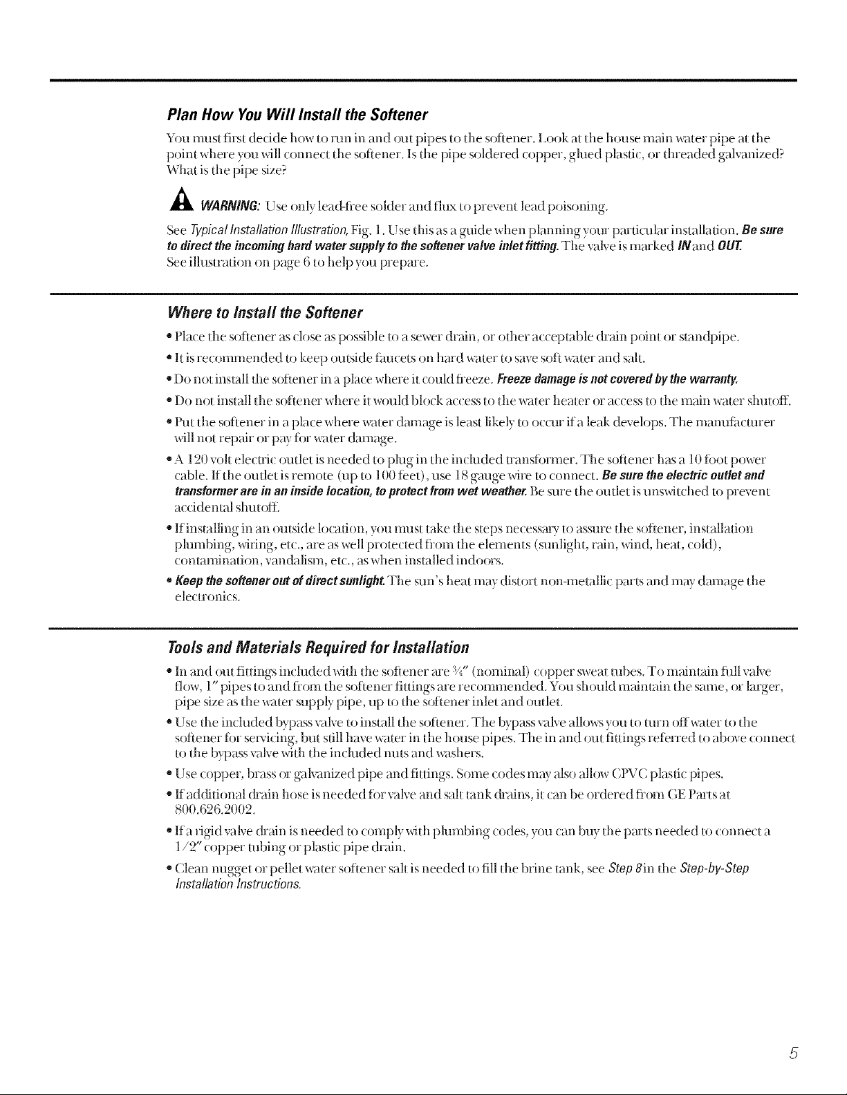
Plan How YouWill Install the Softener
Y(m nmst first decide how to nm in and out pipes to tile softener. Ix)ok at tile house main water pipe at tile
point where you xdll conne( t tile sotlener. Is tile pipe soldered (opper, gilled plas0(, or dueaded galvanized?
What is tile pipe size?
_WARNIN6: Use only lea&flee solder and flux to prevent lead poisoning
See YgpicalInstallationIllustration,Fig. 1. U se this as a guide when planning your par0cular installa0on. Be sure
todirecttheincominghardwater supplyto thesoftener valveinletfitting.Tile valve is marked INand OUT
See illusmltion on page 6 to help you prepare.
Whore to Install the Softener
• Place d_e softener as (;lose as possible to a sewer drain, or odier acceptable drain point or smn@ipe.
• It is recommended to keep outside thucets on hard water to save soft water and salt.
• Do not install tile softener in a place where it could fleeze. Freeze damage is not covered by the warranty.
• Do not install tile softener where it would block access to tlle water beater or access to tlle main water slmt oil.
*Put tile softener in a place where water damage is least likely to ocolr ifa leak develops. The manutiJcmrer
will not repair or PW tor water damage.
*A 120 volt electric outlet isneeded to phlg in tl_e in( bided nansiinmer. The sotiener has a l 0 toot power
(able. If tile oudet is remote (up to 1O0te_et),use 18 gauge xdre to connect. Be sure the electric outlet and
transformer are in an inside location, to protect from wet weather. Be sure tile oudet isunswit(hed to prevent
a( cidenml shutoiL
• If installing in an outside loca0on, you nmst take tile steps necessa U to assure the softener, installation
phmlbing, wiring, etc., are as well protected tiom the elements (sunlight, rain, wind, heat, cold),
contamination, vandalism, et(., as when installed indoors.
• Keep the softener out of direct sunlight. Tile sun's heat may distort non-metallic parts and may damage tl_e
electronics.
Toolsand Materials Required for Installation
• In and out fittings in(luded with the softener are %" (nominal) (opper sweat robes. To maintain tifil vah'e
flow, 1"pipes to and tiom the softener fittings are recommended. You should maintain tlle same, or larger,
pipe size as the water supply pipe, up to die softener inlet and outlet.
• Use the included bypass valve to install the softener. The bypass valve all()ws you to mrn offwater to tile
sotiener tbr se_'icing, but still have water in the house pipes. The in and out fittings retFrred to abtwe connect
to dm bypass valve wid_ the inchlded mils and washers.
• Use copper, brass or galvanized pipe and fittings. Some codes may also all()w CIWC plasuc pipes.
• If additional &ain hose is needed fin valve and salt tank &ains, it (:an be ordered iiom GE Parts at
800.626.2002.
=Ifa rigid valve drain is needed to comply with plumbing (;odes, you can buy tile parts needed to connect a
1/2" copper robing or plastic pipe drain.
*Clean mlgget or pellet water softener salt is needed to fill tl_ebrine tank, see Step 8in tlle Step-bg-Step
InstallationInstructions.
5
Page 6
Installationinstructions.
Typical Installation Illustration
Soft water
120-voltoutlet
Hardwater
Hardwaterto
outsidefaucets
Onion(not supplied)(2)
installationnut(2)
cover
removed
GOESHERE
Brineweil
24Vtransformer
J
I
Coppertube,3/4" (2)
_" Pullout forsokwaterservice
-_) " Pushinforbypass
INLET
NOTE:SeeDrain Hose
Connectionssection.
BypassValve
NOTE:Threadsontile bypass
valveare1" malepipe.If1"
pipesareneeded,donot use
thecoppertubesandnuts
included.Buy1" pipetbread
femaleadapter,andplumb
directlyto1" threads.
Optional 3-Valve Bypass Installation illustration
Adaptersforthisinstallationare notsuppliedwith thesoftener.
Toordertheseadapters,callGEParts800-626-2000.(AskforPart#WS6OX10006.)
Softwater
Bypassvalve
Fig. 1
CROSS-OVER
Useifwatersupplyflowsfromtbe left.
includesingleor3-valvebypass.
Hardwater
Fromsotiener^ll II
outlet lrll I1_1]_T°s°ftener
.4_J'f_Y inlet
Hardwaterto
outsidefaucets
120-voltoutlet
24Vtransformer
Outletvalve
MA/N
hfletvalve
Copper
tube,
Wasber(2)
Installation adapter (2) (see above)
INLET
3/4"(2)
NOTE:Threadsontheinstallationadaptersare 1"
malepipe.if 1" pipesareneeded,donotusetbe
coppertubesandnutsincluded.Buy1" pipethread
femaleadapterandplumbdirectlyto I" threadson
installationadapters.
",,_l_lfPIPE- Hardwater
3-valvebypasssystem
Forsoftwaterservice:
• Opentbe inletandoutlet
valves
• Closethebypassvalve
Forbypasshardwater:
• Closetheinletandoutlet
NLit(2)
valves
• Opentbe bypassvalve
Fig. 2
Hardwater
Fromsoftener
outlet
Tosoftenerinlet
CROSS-OVER
Useif watersupplyflows ftom
tbeleft. Includesingleor
3-valvebypass.
Page 7
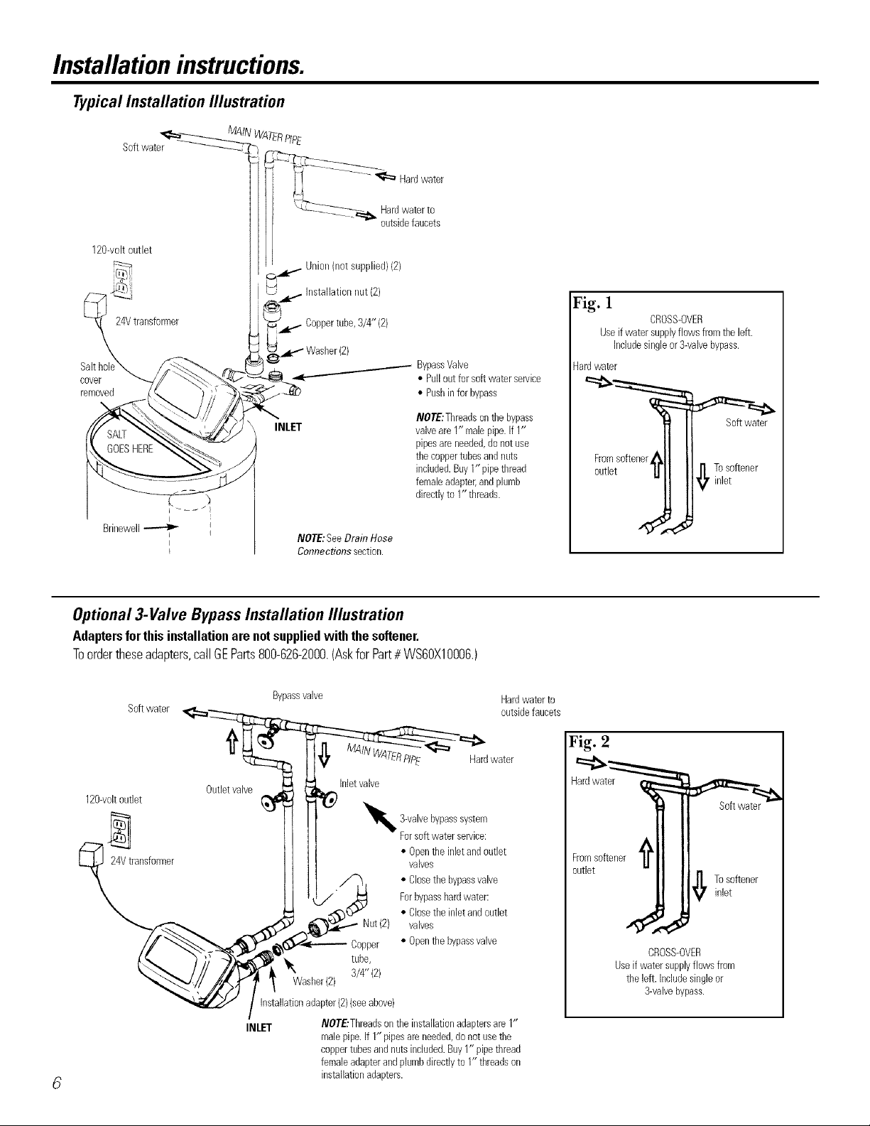
Step-by-stepinstallationinstructions.
• Turn off the gas or elecuic supply to tile water heater, in tile possibiliff that the
water heater may be chained while &aining pipes.
Fig. 3A
• Turn off the w;iter supply to pipes to be cut and chain the h_)use water pipes.
• Open both hot and coM fimcets.
1.INSTALL BYPASS VALVE
• Rem()ve plastic shipping plug and wire flom valve outlet.
NOTE: Be sure the turbine
and support me firmly in
Turbine
place in the xvtlve outlet.
Blow into the xvdveport
and observe the turbine
tot fiee rotation.
• Push the bypass xvdve (lubricate o-ring seals with silicone grease) into both ports
of the valve as shm_ql in Fig. 3A. Fig. 3B
° Snap the 2 large plastic clips in place, flom the top, dox_11as shox_i_ in Figures 3A
and 3B. Be sure they snap into place. Pull on the bypass valve to make sure it is SIDE
held securely in place. VIEW
2. MOVE THE SOFTENER ASSEMBLY INTO INSTALLATION POSITION:
e outlet
Turbine sMft
and suppo_
Met
O-ringsealgoesinto
the outergrooveonly.
Theclipsnapsintothe
innergroove(see
below).
• Be sure the installation suriime is level and smooth. Sharp objects under tile tank
mW puncune it. If needed, place the lank on a section of 3/4" thick (minimum)
pl)wood. Then, place shims under the pl)wood as needed to level the softener.
3, PLUMB INAND OUT PIPES TO AND FROM SOFTENER:
CAUTION: Obsecve all of tile tbllowing cautions asyou connect inlet and
outlet plumbing. See Fig. 1or 2.
• BE SURE IN( OMING HARD WATER SUPPI N IS DIRECTED TO THE
SOFTENER VA137E INLET PORT. If house w;tter flow isfioln the left, use a
plumbing cross-over as shox_l_in Fig. 1.
Fig. 3C
• If making a soMered copper installation, do all sweat soldering before connecting
pipes to the bypass,calve. Torch heat will damage plastic pmls.
• When turning threaded pipe fittings onto plastic fittings, use care not to
cross-thread.
° Use pipe joint compound on all external pipe flneads.
• )"
Support inlet and outer phnnbing in some manner (use pipe hangers) to keep
the weight off of the valve fittings.
4. CONNECt AND RUN THE VALVE DRAIN HOSE:
Fig. 4
° Use tile provided dr?fin hose (20' length included) to attach to tile valve &ain
fitting. To keep water pressure tiom bh)wing tile hose off, use a hose clamp tO
seone in place.
• I_ocate the other end of the hose at a suitable drain point (floor drain, sump,
laund U rob, et_.) that temfinates at the sewer. Check and comply with local codes.
IMPORTANT: If more drain hose is needed, it sh{)uM be ordered flom GE Pmts
at 800.626.2002. The water softener will not work if water cannot exit this hose
during regenerations.
• Tie or wire the hose in place at the drain point. High water pressure will cruise it to
whip during the back-w:tsh and tast rinse tycles of regeneration. Also provide an
ak gap of at least 1-1/2" between the end of the hose and the drain point. An air
gap prevents possible siphoning of sewer water into the softener, if the sewer
sh_)uld "back-up."
° If raising tlle drain hose overhead is required to get to file drain point, do not
raise higher than 8' above the floor. Elevating the hose may _ause a ba_ k-pressme
that could reduce brine draw during regenerations.
J
Valvebodyinletor
outlet
Valye
drain
hose
Clip
Outlet
Bypassvalve
NOT£'Thmadsonthe
bypassvalveam1" male
pipe.if1" pipesareneeded,
donot usethecoppertubes
andnutsincluded.Buy 1"
pipethreadfemaleadapter,
andplumbdirectlytoI"
threads.
Clip
X END
VIEW
Q
Bypassvalve
(pushall the way in)
Turnbypassvalve
upsidedownto
connecttofloor
levelplumbing
STANDPIPE
ur gap
FLOORDRAIN
1½"airgap 7
Page 8
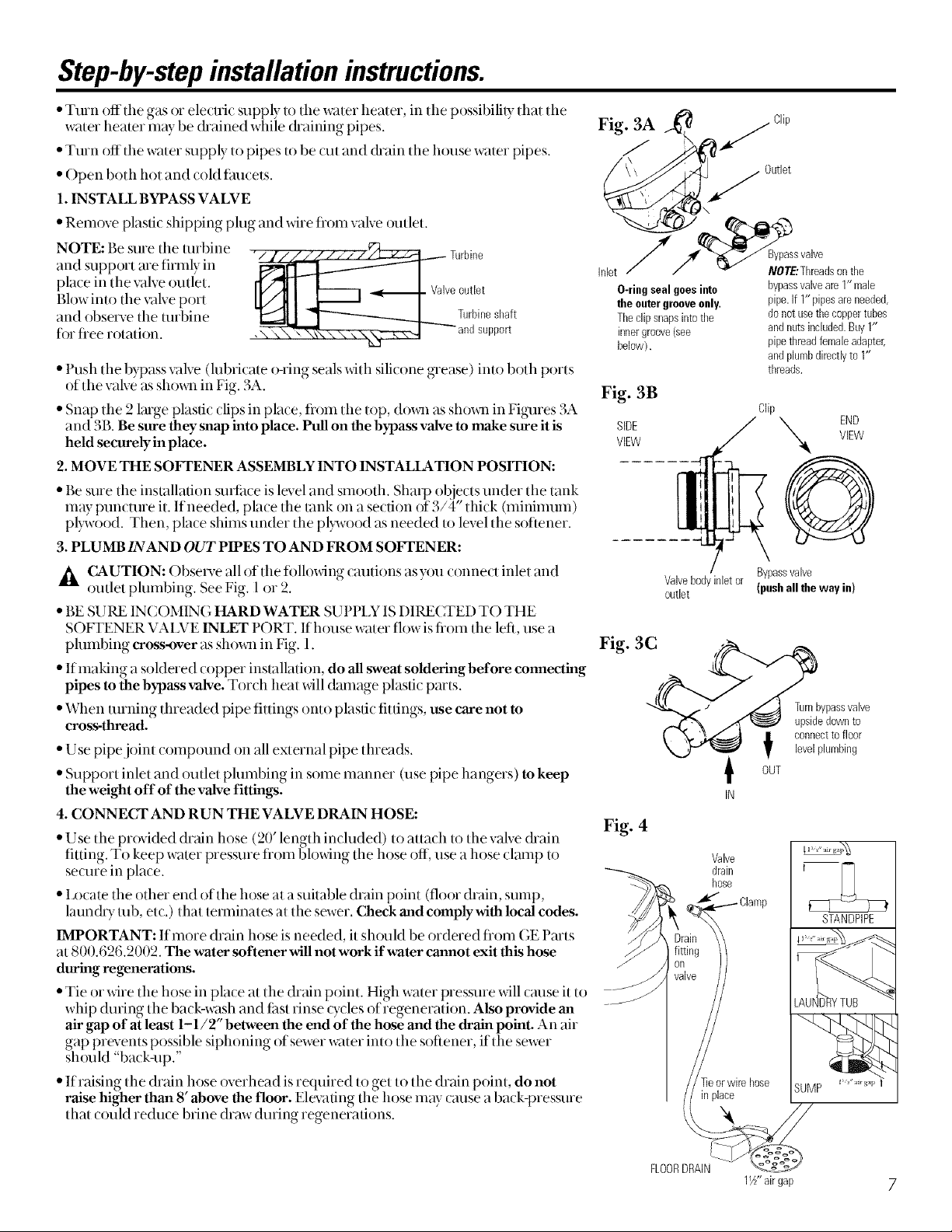
Step-by-stepinsta/lation instructions.
4A. CONNECTING A RIGID VALVE DRAIN TUBE Fig. 4A 1/4"NPTthreads
from tile drain fitting as shown in Fig. 4.4. Rotate tile drain lifting so tile cutting Barbs coppertube{net
•To adapt a (ol)per &ain robe u, the s(,Jr/ener, use a ha(ksa,, to (ut dm bmbe den d --7_/h _/" t.__? 1/2" O.D.
blade,dears,tile.xake housing,,t°,prevent (kmlage,to vake. Buv..a (ompression, lit ring, j ,. ::' i_ furnished)
(1/4 female pipe dnead x l/2 ().D. robe) and needed robing from your local
hardware store.
5. INSTALL THE BRINE TANK OVERFLOW FITTINGS AND HOSE OH
InseHtherubbe_ gtommetmtoflle3/4 dlametel hole in dm brine tank sidewall eutbarbs
asshown in Fig. 5. fromdrain Compressionfitting,1/4"
• Pushthe end of din hoseadapter elbow into tile grommet asshown in Fig.5. fitting NPTX1/2"0.D.tube(not
•Attach alenelh of hose (userem_fining hoseflom Step 4) to tile hose adapter furnished}
elbow. L sea hose clamp to hold U m place. Fig. 5
• Locate tile other end of the hoseat tile drain point. DO NOT ELEVATE this hose
higher than the elbow on tile brine tank.
IMPORTANT: DO NOT TEE OVERFLOW HOSE TO VALVE DRAIN HOSE. \ S
NOTE: This drain is fi)r safety only If tile tabinet (brine tank) shoukl over-till with
water, tile ex(ess is (anted to tile drain.
6. INSTALL GROUNDING C_AMPS AND WIRE pter
A DANGER: Failure to properly atta(h ground wire tould resuh in electri(al sho(k.
• If plumbing is metal, u) maintain electrical ground continuity in tile house (:okl
water piping, install tile included ground ( kunps as shown in Fig. 6. Be sure tlie Grommet
pipes are (lean llndei tile clamps to assuie good cent}tot. Donotconnecttovalve
7. FLUSH PIPES, EXPEL AIR FROM SOFTENER, AND TEST YOUR
INSTALLATION FOR WATER LEAKS:
A CAUTION: To avoid water or air pressure damage to softener inner parts,
be sure to do the following steps in exact order.
A. Fully open 2 cold soft water faucets nearby the softener.
B. Place bypass valve in "bypass" position by pushing the stem inward, drain
C. Fully open the house main water pipe shutoff valve. Observe a steady flow from Fig. 6
both faucets opened in step A, above. Tuvalvehdet
D. Place bypass valve in the "service" position EXACTLY as follows. KEEP SOFT
WATER FAUCETS OPEN.
SLOWLY pull or slide the valve stem (out) toward the service position, pausing
several times to allow the softener to pressurize slowly.
E. After about 3 minutes, open a HOT water faucet for 1 minute, or until all air
is expelled, then close. NOTE: If water appears t loudy or has sahy taste, allow to wire
run fiw several more minutes, or until clear.
F. Close allwater faucets.
G. Check your plumbing work for leaks and fix right away if any are found.
Be sure to observe previous caution notes. Fromvalveoutlet
IZLTurn on the gas or electric supply to the water heater. Light the pilot, if applicable.
8.ADD WATER AND SALT TO THE BRINE TANK:
"I Jfl tile (abinet (brine tank) / oxel. Add about 3galhms of water into tile tank. I)o not add into tile brinewell.
• Fill tank x_ith NUGGET, PEI ] £T or coarse SOLAR water softener sah with a purity of 99.5% or lfigher. Do not use rock, block,
uranulated, and ice cream-making salts, or salt w_th _ron-removmg additwes (except for Ihamond Crystal '_Red.OuP brand sah).
Sah storage capacHv is approxmlatelv 200 lbs. Keep tile sah hole cover m place on the softener unless serxacmg tile unU or rehlhng
with salt.' ....
NOTE: Iftilesoftener isinstalledin a humid basement or oflmr damp mea,itisbetter to fillthe tank with lesssalt,more frequently.
EightytoI00Ibs.ofsallxfilllastlotseve_vdmonths,dependingon waterhardness,familysizeandwatersofteningsystelnmodel
9.CONNECT TO tLECTRICAL POWER:
• Iftransfi)rmer wiring is not visible at tile back of the control bead, remove control cover. DO NOT PUI]. ON OR DIS(_ONNECT
WIRING. I.ocate the long wire with "U" shaped connectors on one end. Route this wire tlnough the rear of the control housing.
Replace the control covei.
• Fasten the 2 power cable lugs ("U" shaped connectors) to the 2 screws on the transformer, and tighten the screws. Then, plug the
transforlner into the electri{:al outlet.
• Tile softener works on 24 voh:60Hz electric power. Tile included transfi)rmer changes stan(bnd 120 voh A( house power to
24 vohs. Plug the transformer into a 120 volt oudet only. Be sure tile outlet is alwayslive so it can not be switched off by inistake.
10. PROGRAM THE CONTROL:
o° • See Programming tile Control se(tion.
• _ Hoseclamp
Y
fT
Overflowdrainhose
drainhose.
To
sewer
Page 9
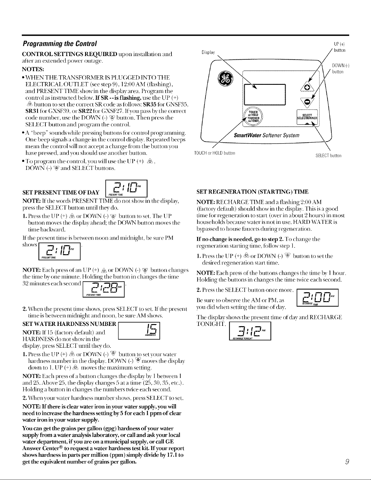
Programming the Control
CONTROL SETTINGS REQUIRED upon installation and
after an extended power outage.
NOTES:
• WHEN THE TIL*_NSFORMER IS PI,UGGED INTO THE
ELECTRICAL OUTLET (see step 9), 12:00 AM (flashing),
and PRESENT TIME show in the display area. Program the
conuol as insu_ucted below, ff SR -- is flashing, use tile UP (+)
/o\ button to set the correct SR code as ti)lh)ws: SR35 fi)r GNSF35,
SR31 ti)r GXSF39, or SR22 ti)r GXSF27. Ifyou pass by tile correct
code number, use the DOWN (-) W button. Then press the
SEI_ECT button and program the control.
• A "beep" sounds while pressing buttons tor conuol programming.
One beep signals a change in the conuol (fisplay. Repeated beeps
mean the conuol will not accept a change flom tile button you
haw pressed, and you should use another button.
• Toprogramtheconuol, youwillusetheUP (+) /o\,
DOWN (-) W and SEI_ECT buttons.
Display
TOUCHorHOLDbutton
UP(4
SmartWater Softener System-_,J
SELECTbutton
SET PRESENT TIME OF DAY .....
NOTE: If tile words PRESENT TIME do not sh_)w in tile display,
press tile SEI_ECT button until they do.
1. Press the UP (+) _ or DO_VN (-) _ button to set. The UP
button moves the display ahead; the DOWN button moves the
time backward.
If tile present time is between noon and midnight, be sure PM
l&
shows _, ff-I,_ I"
C ' 0d
NOTE: Each press of an UP (+) _ or DOWN (-) W button changes
the time by one minute. Holding tile button in changes tile time
32 minutes each second ,_,,_r-_l'l'-I'-i'-'_-I_J_ •
2. When tile present time shows, press SELECT to set. If the present
time is between midnight and noon. be sure AM sh_)ws.
SET WATER HARDNESS NUMBER 11--7-
NOTE: If 15 (facto U defauh) and /,_!
tLa.RDNESS do not show in the
display, press SEI_ECT until they do.
1. Press the UP (+)/o\ or DOX.VN (-) _] button to set w)ur water
hardness number in the display. DOWN (-) W moves the display
down u) 1. UP (+) _ moves tile maximum setting.
NOTE: Each press of a button changes the display by 1 between 1
and 25. Above 25, the display changes 5 at a time (25, 30, 35, etc.).
Hol(fing a button in changes the numbers twice each second.
2. When your water hardness number sh_)ws, press SEI _ECT to set.
NOTE: If there is clear water iron in your water supply, you will
need to increase the hardness setting by 5 for each 1 ppm of clear
water iron in your water supply.
You can get the grains per gallon (gpg) hardness of your water
supply from a water analysis lalmratory, or call and ask your local
water department, if you are on a mmficipal supply, or call GE
Answer Center ® to request a water harthless test kit. If your report
shows hardness in parts per million (ppm) simply divide by 17.1 to
get the equivalent number of grains per .qallon.
ImEs_r rl_
SET REGENERATION (STARTING) TIME
NOTE: RECtL_R(;E TIME and a flashing 2:00 AM
(tacto U detault) should show in the display. This isa good
time fi)r regeneration lo start ((wet in about 2 hours) in most
households because water is not in use. HARD WATER is
bypassed to house fimcets during regeneration.
If no chmage is needed, go m step 2. To change the
regeneration starting time, fifth)w step 1.
1.Press the UP (+) _ or DOWN (-) W button to set the
desired regeneration start time.
NOTE: Each press of the buttons changes tim time by l hour.
Holding the buttons in changes the time twice ea(h second.
2. t tess tile SELECT button once more.
Be sure to observe tile AM or l M, as _ _
you did when setting the time of day.
The display shows tile present time of day and RECHARGE
TONIGHT. I
itECHA PGE TON/Gt/T
, la II I
I
Page 10
Step-by-stepinstallationinstructions.
Sanitizing Procedures
Tocompletetheinstallation,dothe following sanitizingprocedures.
Care is taken at the thctoD_to keep y_)ur water softener clean and sanitmy. Materials used to make tile softener _dll not intect or
contmninate your water supply and _dll not cm_sebacteria to ti_rm or gr_w. H_wever, (hning shipping, storage, installing and
operating, bacteria c{mld get into the softener. For this reason, sanitizing as fifth_wsis suggested when installing.
NOTE:SanitizingisrecommendedbytheWaterQualityAssociationfordisinfecting.
[_Be sure to (omplete all installation steps, in( luding programming tile (onuol.
[_ Pour about 3/4 oz. (l {dtablespoons) of COlnlnon 5.25% household bleach (Clorox, Linco, Bo Peep, White Sail, Eagle, etc.)
into tile brinewell,Refer to illusuation on page 6.
_IMPORTANT: Press and hold fi)r 3 seconds the faceplate TOUCH/HOLDbillion to start an imme(fiate regeneration. RechargeNow
begins to flash in the display. The blea(h is (hm_l into and through the water softener.
[_] If after sanitization water flOln house thucet tastes sahv or has a slight color, this is a present,alive fiom the resin tank. Turn on
the cold soft water fimcets and &ain fi)r a few minutes or until clear.
NOTE'Whenthe above sanitizing regeneration is over, your house COLDwater supply is flflly soft imme(fiately. However, your water
heater isfilled with hard water and as hot water is used, it will refill with soft water. When all the hard water is replaced in the water
heater, hot only and mixed hot and cold water will be tully soft. Ifyou want totally soft water immediately, after the ab_ve
reg*_neration, drain the water heater until the water runs cold.
_kWARNING: If you do drain the water heater, use extreme (are as the hot water (ould (ause burns. Turn the water heater off
prior m draining.
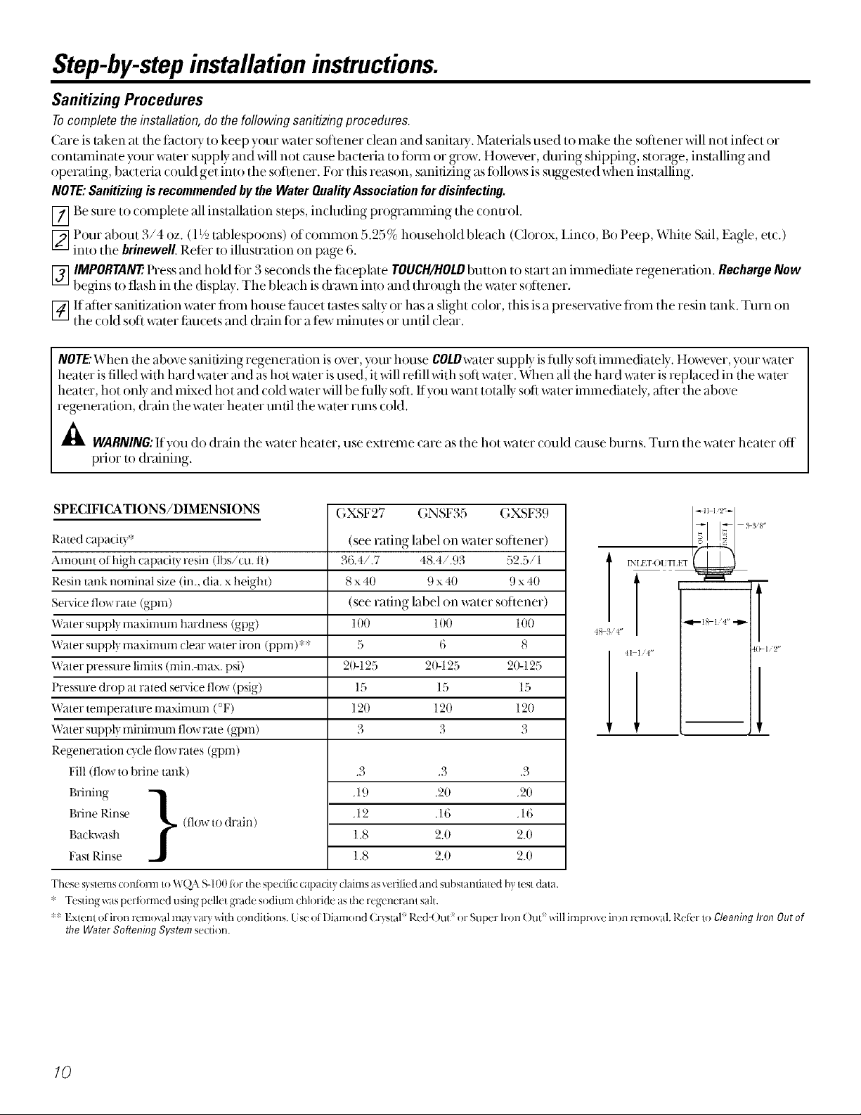
SPECIFICATIONS/DIMENSIONS
Rated capacily*
Amount ofhigh capacit? resin (lbs/cu. fl)
Resin tank nominal size (in., dia. x height)
Se_'ice tlow rate (gpm)
Water suppl) maxinmm hardness (_I _)
O" )o"
Water supply maximum clearwater iron (ppm)**
Water pressure limits (min.-m_e¢.psi)
l'ressure drop at rated service flow (psig)
Water temperature maximum (°F)
Water supply minimum flow rate (gpm)
Regeneration _)cle tlow rates (gpm)
Fill 0low to brine tank)
(,XSF2 ¢ (,NSF3b (,XSF3.)
(see rating label on water softener)
r_, r./l36A/.7 48A/.93 .2.0
8 x 40 9 x 40 9 x 40
(see rating label on water softener)
100 100 100
5 6 8
20-125 20-125 20-125
15 15 15
120 120 120
3 3 3
.3 .3 .3
'ti l't"
"11"--18 I'U
>I '2"
.19 20 20
l?,rine Rinse [low to drain)
l?,ackwash
l?,rining }
FastRinse
These syslems con/k_nnIoWQA S-100li)r the spedlic capadty claimsasvefilied and substantiated by lest dala.
Testing wasperti)rmed using pellet grade sodium chh wide asthe regeneranl sah.
'_'_Extant ol iron removal may varywith conditions, tse ol l)iamond ()ystal Red.Out or Super h-onOut' willimprove iron removal. Ref_r Iogleaning Iron Outof
the WaterSoftening Systemsecdon.
.12 A6 .16
1,8 2.0 2.0
1,8 2.0 2.0
/0
Page 11
Aboutthe water softener system.
Service
When tile _cater softening system is providing soft water, it is called "Sex,ice." During se,_ice, hard water flows
flom the house main water pipe into the water softening system. Inside the x_v_tersofienh_g system resin tank isa
bed made up of d_ousands of tiny, plasti( resin beads. As hard water passes d_rough the bed, each bead ama( ts
and holds tl_e hard minerals. This is (:ailed ion-exclmnging. It isnmch like a magnet amacting and holding
metals. \,\_lter without hard minerals (soft water) flows fiom the water sofiening systeI_n and to tlm house pipes.
After a period of time, the resin beads become coated with hard minerals and dmy have to be cleaned.
This cleaning is called regenem0on, or re( harge. Regeneration is started tit 2 00 AM (fh(to U sening) by tlle
water softening system control, and consists offixe stages or o,cles. These are FILLBRINING,BRINERINSE,
BACKWASHandFASTRINSE
Automatic Hard Water Bypass During Regeneration
For emergency needs, hard war er is available to the However, you should avoid using HOT water because
home during the regeneration cycles the water heater will fill with the hard water.
Fill
Salt dissolx ed in water is called brine. Brine is needed to clean tl_e hard minerals flom resin beads. To make the
brine, water flows into tim salt storage area during the fill stage.
Brining
During brining, brine m_xelsflom the salt storage area into the resin tank. Brine is the cleaning agent needed
to remove hard minerals flom the resin beads. The hard minerals and brine are dis( barged to tile drain.
The nozzle and venturi (reate a su( tion txxmove the brine, maintaining a veIT slow rate Ixxget the best resin
(leaning _4th the least sail.
Brine Rinse
After a pre-measured amount of brine is used, the brine xake (loses. Water continues Io flow in tim same path
as during brining, ex(ept fbr the dis(ontinued brine flow. Hard minerals and brine flush flom the resin tank Io
the drain.
Backwash
During ba(kwash, water m_ els up through the resin tank at a f:astflow rate, flushing a((umulated iron, dirt,
and sediments flom the resin bed and to drain.
Fast Rinse
Backwash is fbll_med by a fiJst fl_m of water down through tlm resin tank. The fiJst fl_rw flushes brine flom the
bottom of tank, and pa(ks the resin bed.
After thst rinse, tlm water softening system returns to soft water servi(e.
II
Page 12
Aboutthe water softener system.
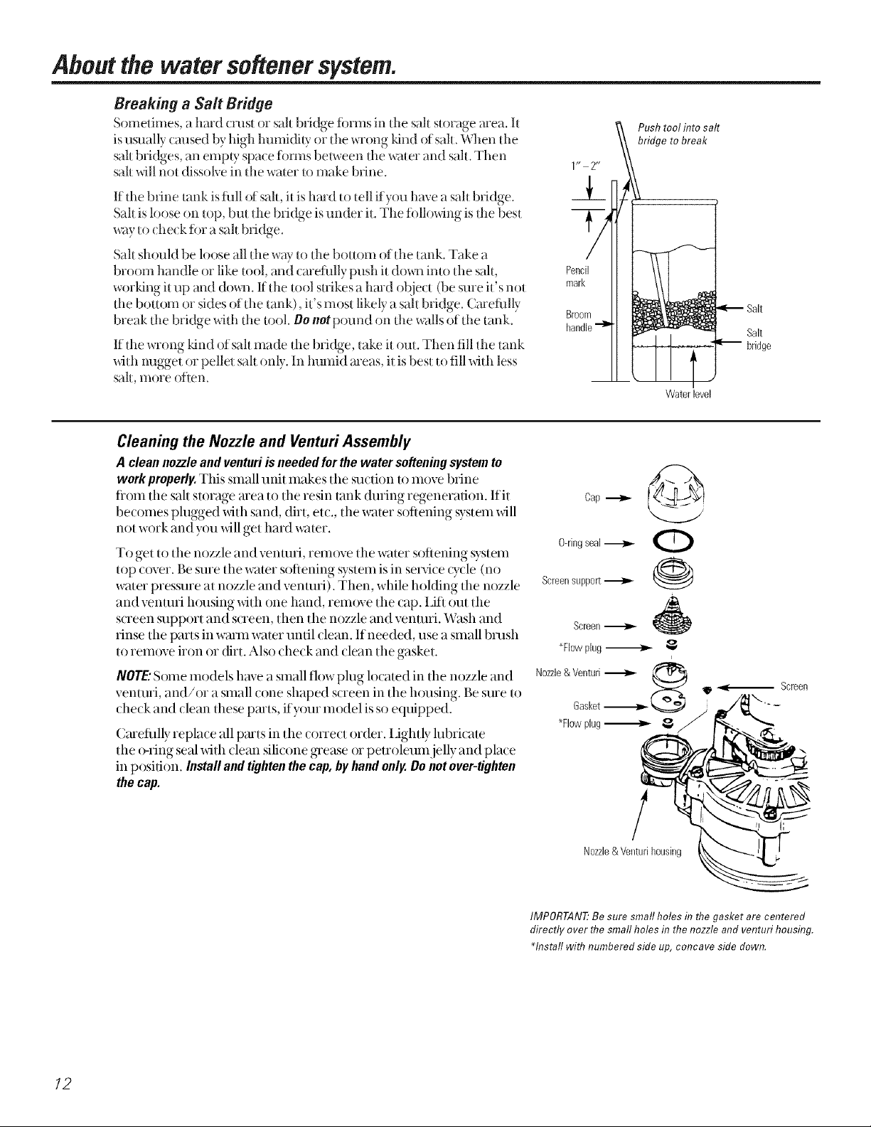
Breaking a Sail Bridge
Sometimes, a hard crest or salt bridge fiwms in tile sah storage area. It
is umally cruised by high humidity or the wrong Idnd of sah. When tile
sail bridges, an empty space fi)rms between the water and salt. Then
sall will not dissolve in the water to make brine.
If tile brine tank is flfll of salt, it is hard to tell if you ha,_e a salt bridge.
Sah is loose on top, but tile bridge isunder it. Tile fi)llowing is tile best
way to (he(k fi)r a salt bridge.
Salt should be loose all the way to tile bottom of the tank. Take a
broom handle or like tool, and carefiflly push it do_m into tile salt,
worldng it tip and do_m. If tile tool suikes a hmd object (be sure it's not
the bou()m or sides of the tank), it's most likely a salt bridge. Carefiflly
break the bridge with the tool. Oo not pound on the walls of the tank.
If tile wrong kind of salt made tile bridge, take it out. Then fill tile tank
with nugget or pellet salt only. In humid areas it is best to fill with less
sail, I;tlore otlen.
Cleaning the Nozzle and Ventufi Assembly
A cleannozzleandventuriisneededforthe watersofteningsystemto
workproperly.This small unit makes tile surtion to move brine
fl'om tile salt storage area to tile resin tank during regeneration. Ifit
becomes plugged with sand, dirt, etc., the water softening system will
not work and you will get hard water.
To get to tile nozzle and venmri, rem()ve tile water softening system
top cover. Be sure the wamr softening system is in service (ycle (no
water pressure at nozzle and venuni). Then, while holding the nozzle
and venmri h()using with one hand, rem()ve the cap. IJfl out the
screen support and soeen, then the nozzle and venmri. _¢\_Bhand
rinse the parts in warm water until clean. If needed, use a small brash
to remove iron or dirt. Also check and clean the gasket.
NOTE."Some models have a small flow plug located in tile nozzle and
venmri, and/or a small (one shaped screen in the housing. Be sure to
(lle(k and )lean these paris, ifyour model is st) equipped.
( mefillly replace all p_uts in tile correct order. IJghtly lubricate
the o-ring seal with clean silicone grease or petroleum jelly and place
in position. Installandtightenthecap,byhandonly.Donotover-tighten
thecap.
Push tool into saltbridge to break
1 r* 2**
Y
Pencil
mark
Broom
handle"-_
Cap ._
O-ringseal_
Screensupport ,,--I,,,-
Screen_ _
_Flowplug_
Nozzle&VenturiGasket_ $
*Flewplug_
Salt
Waterlevel
i
12
/
Nozzle& Venturihousing
IMPORTAN# Be sure small holes in the gasket are centered
directly over flTesmall holes in the nozzle and venturi housing.
Hnstall wifl7 numbered side up,concave side down.
Page 13
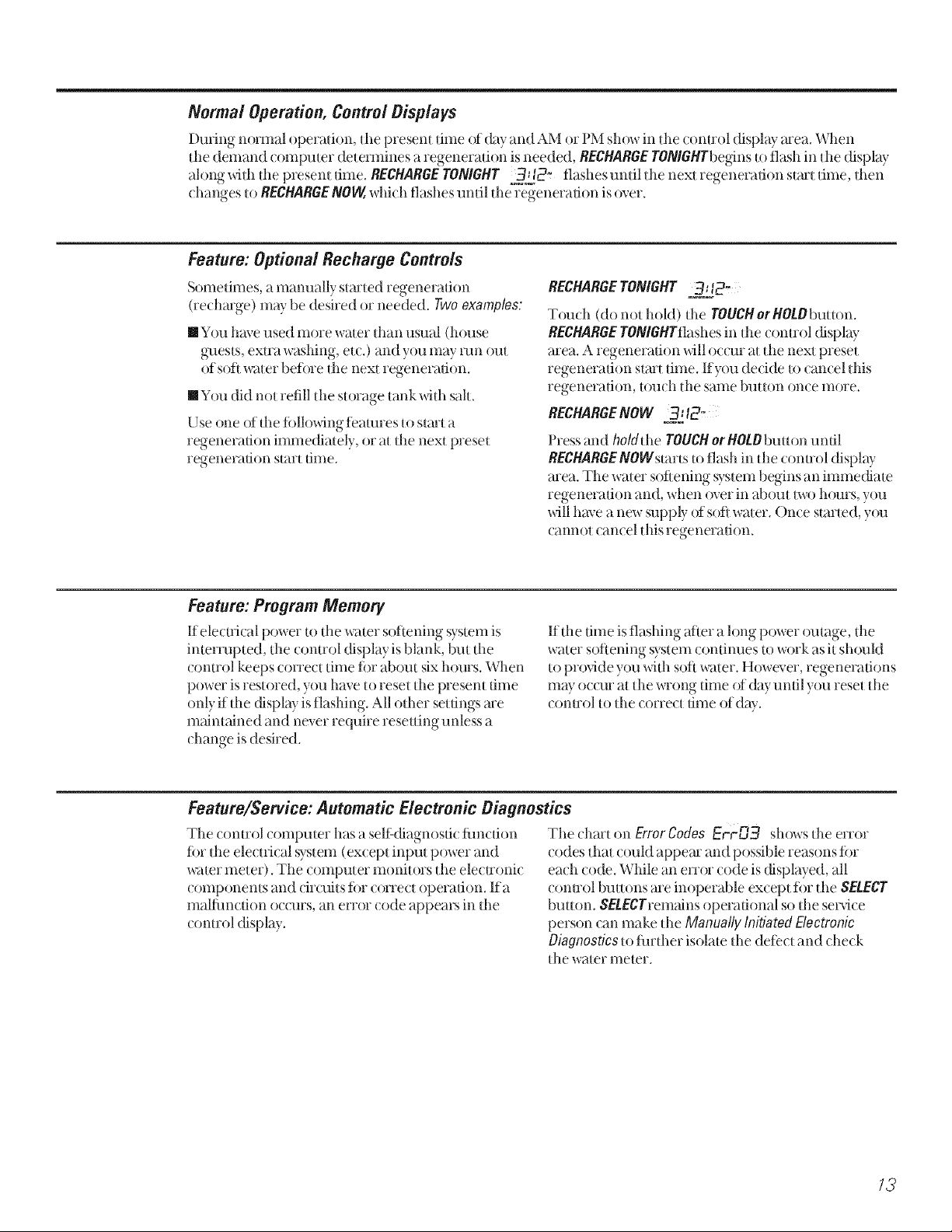
Normal Operation, Control Displays
During normal operation, )he present time of day and AM or PM show in dm (onuol display area. When
)lie demand ( omputer determines a regeneration is needed, RECHARGETONIGHTbeginsto flash in )lie display
along _dlh the presenl fime. RECHARGEYO/vlGHY 32j2" flashesunfildmnexlregenerafionslarllime, fl_en
(hanges U)RECHARGE/VOW,whi(h flashes until the regeneration is over.
Feature: Optional Recharge Controls
Sometimes, amanually stmled regeneration
(recharge) may be desired or needed. Two examples:
[] You have used more waler than ualal (house
guests, exUa washing, etc.) and yotl may mn out
of soft waler befi)re fl_e next regeneration.
[] You did nol refill d*e storage rank whh sail.
Use one of the fi)llowing ieamres to stmt a
regeneration immediately, or aI Ihe next preset
regeneration slarl time.
Feature: Program Memory
If ele(uical power to dm wmer soiiening system is
interrupted, the control display is blank, but fl_e
(onu'ol keeps correct time fi)r about six hours. When
power is restored, you have to reset the presem time
only if fl*edispl W is flashing. All oilier seuings me
m_fint_fined and never require resetting unless a
(hange is desired.
RECHARGETONIGHT 3]" 2,
Touch (do not hold) tim TOUCHorHOLObuuon.
RECHARGETO/vlGHTflashes in tile control display
area. A regeneration will occur at the next preset
regeneration start time. If you decide u) cancel this
regeneration, u)uch the same buuon once more.
RECHARGE/VOW 3_12_
Pressand ho/&he TOUCHorHOtObuuon until
RECHARGE/vOWst'artsto flash in tim (onuol display
area. The water sofiening system begins an immediate
regeneration and, xdmn oxer in about Ix_ohours you
will haxe a new supply of sod water. ()nee s)aned, you
(annot (an(el [his regeneration.
If tile time is flashing after a long power omage, tile
water soiiening system ( ontinues to work as it sh_)uld
to pro)vide you _dth soil water. H_)wever, regenerations
mW oc(ur at the wrong time of dayuntil you reset tile
(onnol to tl_e(orre( t time of dW.
Feature/Service: Automatic Electronic Diagnostics
The control compmer has a seli:(fiagnosfic fimcfion
fin tl_e ele( tri( al system (except input power and
water meter). The (omputer monitors the elecuoni(
(omponems and (irofits fi)r correct operation. Ifa
malfimction oc(:urs, an err_)r code appears in fl_e
conu:ol display.
The chart on ErrorCodes Er-rU3 shows the error
(;odes that could appear and possible reasons ior
each (:ode. While an error code is displayed, all
control bretons are inoperable except fi)r the SELECT
buuon. SEtECrrem_finsoperational so d_e service
person can make tl,e Manually Initiated Electronic
Diagnosticsto innher isolate fl_edeiect and check
tile water meter.
/3
Page 14
Aboutthe water softener system.
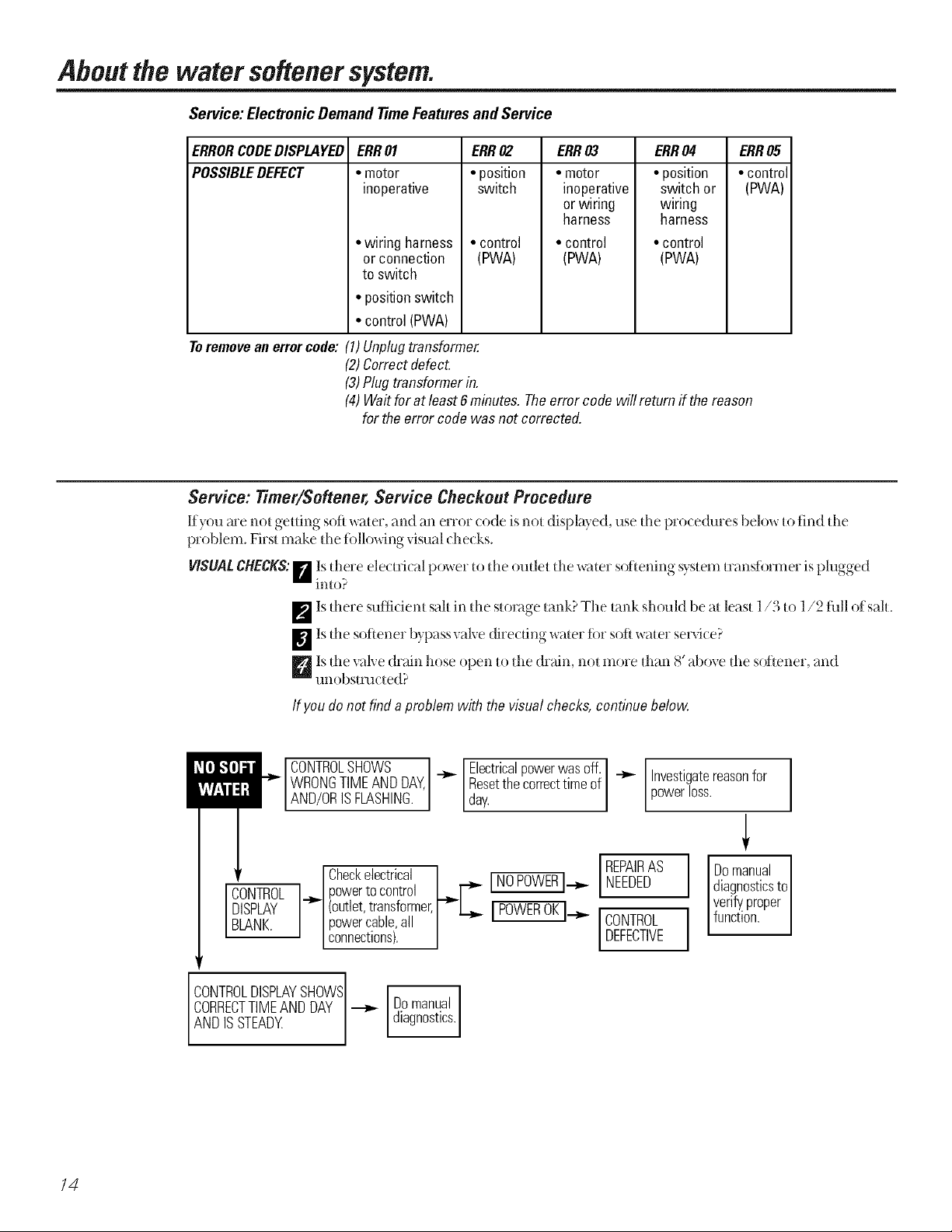
Service: Electronic Demand 77meFeaturesand Service
ERRORCODEDISPLAYED ERR03 ERR04
POSSIBLEDEFECT
Toremovean errorcode: (1)Unplugtransformer.
ERR01
• motor
inoperative
• wiring harness
or connection
to switch
• positionswitch
• control(PWA)
(2)Correctdefect.
(3)Plugtransformerin.
(4)Waitforat least 6minutes.Theerror code willreturn if the reason
for the error codewas not corrected.
ERR02
• position
switch
• control
(PWA)
• motor
inoperative
or wiring
harness
• control
(PWA)
• position
switch or
wiring
harness
• control
(PWA)
ERR05
• control
(PWA)
Service: Timer/Softener, Service Checkout Procedure
If you me not getting soft water, and an error (ode is not displayed, use tile l)ro(edures below to find tl_e
problem. First make [l_e%11()-_dngvimal (he( ks.
VISUALCHECKS:[] Isthere ele( tri( al power m dm oudet dm water softening system mmsfbrmer is plugged
imo?
_p'_Isdmre sufficient sail in dm storage lank? The tm_kshoukl be at least l/3 t() l/2 fhll ofsah.
_Is dm softener bypass valve direcdng water for soft water serx4ce?
Dis dm valve drain hose open Io dm drain, nol more d_an 8' aboxe d_e softener, and
tlnobs[Ftl(:[ ed?
If youdonot finda problemwith the visualchecks,continuebelow
CONTROLSHOWS I
WRONGTIMEANDDAY,
AND/ORSFLASHNG.
CONTROL
DISPLAY
BLANK.
CONTROLDISPLAYSHOWS Domanual
ANDISSTEADY
CORRECTTIMEANDDAY_ dagnostcs.
Checkelectrical INOPOWERI.__,,._NEEDED
powertocontrol LJ -_"
(outlet,transformer,r'-L_,. [ POWEROK].__,. I
powercable,all | CONTROL
connectons. | I DEFECTIVE
[Electricalpowerwasoff. _ Investigatereasonfor
[/day.Resetthecorrecttimeof poweross.
IREPAIRAS
Domanual
diagnosticsto
verifyproper
I function.
/4
Page 15
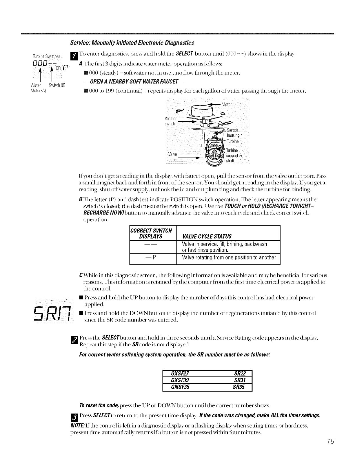
Service: Manually Initiated Electronic Diagnostics
TurbineSwitches [] To enter diagnosdcs, pressand hold [l_e SEI.ECTbullon undl (000 - -) showsin [lie display
_rl m A The firsl 3 digils indicale waler meter operadon asiollows:
IOR P
• 000 (sleady) = soft waler no[ in use_.noflow din)ugh [lie meter.
Water Switch(B)
Meter (A) • 000 tO 199 (condnual) = repeats displ_lyior each gallon of water passing through tl_e meter.
--OPEN A NEARBYSOFTWATERFAUCET--
swi!c/
Sensor
1 _ _)'-housing
I !_Tu[b ine
_Turbine
Valve t_'_l_" Support&
ou!,e! sha,
If you don't get a reading in die display, wid_ faucet open, pull die sensor from d_e; al',e omlet porL Pass
a small magnet back and fbrth in flonl of the sensor. You should get a reading in the display. If you get a
reading, shin of{waler supply, unhook [lie in and ouI plumbing and (hetk die [urbine ior binding.
BThe letter (P) and dash (es) indicate POSITION swhch operation. The letter appeming means tl_e
s_4t(;h is closed; d_e dash means tl_e swhch is open. Use the TOUCHor HOLB(RECHARGETONI6HT-
RECHARGENOW)buuon to mamlally advance die valve imo each Q,cle and check corred switch
operation.
CORRECTSWITCH
DISPLAYS
VALVECYCLESTATUS
Valvein service,fill, brining,backwash
orfast rinse position.
Ep
Valverotatingfrom one positionto another
CWhile in this diagnostic screen, the fi)llowing infi)rmation is available and may be benefidal for various
reasons. This intormation is retained by the computer fiom the first time electrical power isapplied to
the control.
• Press and hold the UP button to display the number of days this control has had electrical power
applied.
• Press and hold the DOWN button to display the number of regenerations initiated by this control
since the SR code number was entered.
F_ Press the SELECTbuttonand hold in three seconds until a Service Rating code appears in the display.
Repeat this step if the SRcode is not displayed.
Forcorrect water softening system operation,the SRnumbermustbe as follows:
GXSF27 SR22
GXSF39 SR31
GNSF35 SR35
Toresetthecode,pressthe L l or DO'vVN button until the correct number shows.
_] Press SELECTto rettlrn to the present time display, tithe cedewaschanged,makeALLthetimersettings.
NOTE:If the (ontrol is left in a diagnosti( display or a flashing display when setting times or hardness,
present time automatically returns ifa button is not pressed within ti)tli minutes.
/5
Page 16
Aboutthe water softener system.
Service: Manually Advance Regeneration Check
Tiffs check verifies proper operauon of tlle valve motor, brine tank fill, brine draw, regeneration fit)w rates and other (omroller
flmcdons. First, make tile initial checks and file Manually Initiated Electronic Diagnostics.
NOTE:The connol display nmst shrewa steady dine (not flashing).
F_ Press fl_e TOUCHorHOLDbutton and hoki in fin duee seconds. RECHARGENOWbegins m flash as the x_wtersoftening system
enters the fill Q,cle ofregenerauon. Remove the brinewell (over and, using a flashlight, obse_,e fill x_wterentering tl'le brine
tank. If water does not enter tl_e tank, look ti)r an obstm( ted nozzle, venmri, fill fl(rwphlg or brine robing. See Care and cleaning
ofthe water softenersystem secuon.
_ Atier obserx4ng fill, press dm TOUCHor HOLDbutton t()move d_e water softening svstem into brining. A slow flow ofwater to the
drain will begin. Veri_ brine (haw fiom the brine tank by shining a flashlight imo dm brinewell and obserx4ng a nod( eable (hop
in tile liquid level over an extended period of time.
NOTE:Be sure a salt bridge is not preventing water fiom contacting sah. See Care and cleaningof the water softeningsystem section.
If thewater softening systemdoesnot draw brine,check:
[] nozzle and/or venmri dirty or detective. [] detective nozzle and venmri seal
[] nozzle and venmri not seated properly on gasket. [] odler inner valve deter t (rotor seal, rotor & disc, wave washer, eL(.).
[] restri( ted drain (check drain fiuing and hose).
NOTE:Ifwater system pressure islow, an elevated &ain hose m W (arise balk pressure, stopping brine draw.
W] Again, press the TOUCHorHOLDbutton to move tile water sofiening system into backwash. I x)ok ti)r a fast flow of water fiom dm
d;ain hose. A slow flow indicates a plugged top distributor, backw_'M_flow plug, or drain hose.
D Press tl_e TOUCHorHOLDbutton to moxe the water softening system into £tst rinse. Again look tora ti_stdrain flow. Allow
tlle water softening svstem to rinse fin a few minutes to flusl'l t£ut any brine dial may ,)emain in fl_e resin tank flom tlle brining
()'cle test.
_Toremrndmwater sofieningsvstemmservi(e pressdm TOUCHorHOtDbmton.
Careandcleaning of the water softeningsystem.
Checking the Salt Storage Level and Refilling
Brine (salt dissolved in water) is needed tor each and eve_Tregeneration. The water fi)r making brine is metered into tile salt
storage mea by tile water soliening system valve and conuol. However,youmustkeepthetank supplied withsalt.
When to refill with salt: Check tile salt level a tew weeks atier you install tile water soliening system and eve D"week after that. Refill
when the brine rank is tiom l/3 to 1/2 fifll. In humid areas it is best to fill with lesssalt more olien. Never all()w tile water soliening
system to use all the salt beti)re you refill it. Without salt, you will soon have hard water.
Use clean water sotiening salts only, at least 99.5% pure. NUGGET, PEII_ET or coarse SOLAR salts me recommended. De net use
rock,block,granulatedoricecreammakingsalts.They contain dirt and sediments, or nmsh and cake, and will create maintenance
problems.
CAUTION:Waterse#ening salt with ironremoving additives:Some salts may have an additive to help the water softening system
handle iron in the water supply. Although this additive may help to keep the water sotiening system resin clean, it may also
release corrosive flmms that weaken and shorten the lite of some water sot/ening system pmts. GE recommends using only
Diamond Cusml' Red.Duff brand salt.
Cleaning Iron Outof the Water Softening System
Your water softening system takes h_udness minerals (caldum and magnesium) out of the water. Also, it can control some (see
Specification Guidelinessection) "clear water" iron. With clear water iron, water fiom a timcet is clem when first put into a glass. After
15 to 30 minutes, the water begins to cloud or turn rust colored. A water soliening system will notremove any iron that makes the
water cloudy or rusly as it comes tiom the taucet (called red water iron). To rake red water iron out of water, or over the maximum
of clem water iron, an iron fiher or other equipment is needed.
GE recommends using only Diamond Custal '_Red.Duff brand salts with hon Fighter '_additive to help keep the resin bed clean of
clem iron. Ify{)ur water supply has clear water iron, periodic resin bed cleaning is needed. GE recommends using Super hon Out"
brand resin bed cleaner to thor{)ughly clean your resin bed ify{)ur iron content is high. (lean the bed at least eve U six months, or
more often if iron appears in the sot/water belween cleanings.
IMPORTANT:It is important to mix the resin bed cleaner with water (tollowing the mamlthcmrer's insmlctions), pour it into the
Orinewell tube (see page 6) and regenerate the softener immediately. Do not pour the resin bed cleaner in xdth the salt, as it will not
be as ettecfive in cleaning the resin, and can cause damage to the sot/ener if it is let/in the brine tank ti)r an extended period due to
the corrosive gases that are limned.
16
Page 17
Troubleshooting 77ps
Save time and money! Review the chart on this
page first and you maynot need to call for service.
NO SOFT WATER - Most Common Problems:
Check the following before calling for service
• Not enough salt in softener-should be at least 1/3 full.
• Bypass vane in "Bypass" position-should be in "Service" position. Knob should
be in the OUT position.
• Hardness setting too low-Check hardness setting in control. Veri_ hardness of
supply water. Water hardness can vary throughout the year. See Programming the
Control section.
• Salt Bridge; water not in contact with salt-see Breaking a Salt Bridge section.
Problem PossibleCauses What ToDo
No soft water Faucet or fixture where sample was
taken not plumbed to soft water.
NOTE"Besuresampleis froma faucet
that doesnot mixsoft andhard water.
Forexample,a singleleverkitchen faucet,
if thecold side isplumbedto hard water
No salt in the brine tank or
salt bridged
Transformer unplugged at wall outlet or
power cable to softener not connected.
Fuse blown or circuit breaker popped
on circuit to electrical outlet.
Electrical outlet on a circuit that can
be s_itched off
Manual bypass valve in bypass position ° Be sure the bypass valve stem is positioned properly, xdth the
Valve drain hose pinched, plugged,
elevated too high or otherwise
restricted
• To conse_a:esalt, the installer may haw isolated some
fixttaes (outside thucets, toilets, etc.) flom soti _'ater.
From the outlet of the water softening system, uace the
water flow path, in house plumbing. If soti water is not
directed to a tm_cet or fixture where wanted, consult
a plumber.
• Check fin a salt bridge or, if the lank is empty, refill with
recommended salt. Press (fin 3 seconds) the TOUCHor
HOLDbutton to start an immediate regeneration and restore
soft water supply.
°Check fin a loss of elecuical power to the w:tter
sotiening system, due to any of these conditions and
correct as needed. With the power supply restored,
observe the taceplate time display and read Program
Memorysecuon. NOTE"Theelectricaloutletforthe softener
shouldbecontinuouslyliveso# cannot be accidentally
switched off.
hmb in the OUT position. Observe instructions on the decal
at the end of the stem.
• Any restriction in this drain hose ma) prevent {)roper
operation of the nozzle and venturi and reduce or
prevent brine (haw during regenerations.
Nozzle and venturi dirty, incorrectly
assembled or damaged
•ReFerto CleaningtheNozzleand VenturiAssemblyinstmctions.
With water pressure to the water soliening system off,
take the nozzle assembly apart. Inspect, clean and
replace as needed. Any fi)reign particle (s), scratches,
nicks, etc., in the passages can prexvnt operation. Besure
holes in the gasket are cenmred ox>r holes in the housing.
/7
Page 18
Before you call for service...
Q\ Troubleshooting -tips
Problem Possible Causes What To Do
Waterhardsometimes Using hot water while the water *Avoid using hot w_lter during w_ltersoftening system
softening system is regenerating regener;ldons bec;mse the w_ter heater _dll reiill with
h_adw_ter. SeeAutomatic Hard WaterBypassDuring
Regenerationsecdon.
Control hardness number setting , Press _md rele_lse the SEtECTbuttonuntil HARDNESSsh_)ws
too low in tile dispiriT. Be sure the number shown is tile same as
the _zttual grains per gallon hardness of yore w_lter
supply. See the Controlse( tion ira t hange in the seuing
is needed.
Grains of hardness in your water • W_t er hardness can change over time, especially in
supply have increased well water. To check, have the water tested by _lw_lter
analysis labor_to_y or tall your loc_d w_lter department.
A(!iust the hardness number setting as needed.
Water feels slippery Absence of hardness minerals • This is normal.
after installation of
water softening system
Water softening system Water softe_fing system is a , Does not use muth salt to regenerate-very eflitient.
not using any salt "demand" unit
Possible salt bridge • See the Operating Instructions, Tipsse(tion.
Possible plugged nozzle and ventu6 • See the Operating Instructions, Tipssection.
Water is blue color Acidic water in copper plumbing • Have the water tested at once.
after water softening
system was installed _k WARNING: Do notdrink the water until problem has
been corrected.
Water softening system Meter turbine stuck • ('_all i()r sel_,_i(e.
not regenerating
Sensor wire corroded • Call fi)r ser_i( e.
No power to unit = Check tile tircuit breaker or fllses.
Mechanical defect = Call for servi( e.
Cloudiness on glassware Combination of soft water and • This is tailed etching and is permanent. To prevent this
(automatic dishwashers) too much detergent fi'om happening, use less detergent if you have soil water.
\,\Sisl_ glassware in the shortest t_,( le that will gel them (lean.
Salty tasting water Insufficient backwash and • Press and hold TOUCH or HOtObutton until RECHARGE
after installation rinse thne st_Jrts to flash.
• At ( ompleuon of regeneration (Tile (approx. 2 hrs), mn water
from iim{ ets to purge the sail}' water.
Lowwater pressure • Che(k pressure; should be minimum 20 psi.
Restricted drain hose * Clean and reconnect bose.
/oo
Page 19
Problem Possible Causes What ToDo
Resinbeadsshewing Cracked distributor • Call lot se_ice.
upin drinkingwater
andsink
Soundsyoumighthear Running water from the unit into •This is normal.
a drain
Waterhasair bubbles Air in system after installation •_A]ll go away after it runs tbr a while.
andiscloudy
ErrorCode on control Wiring may have worked loose in
control
• Unplug transti)rmer.
• Rem,)ve control cover, release clips on side.
• Check ti)r loose/incorrect wiring connections to elecuonic
board or switch. Reconnect as required.
• Reassemble control o)ver.
• Plug in T_'ansli)rmer.
• Wait six minutes ti)r Error Code to reappear.
• If Error Code reappears, call ti)r sevvice.
/9
Page 20
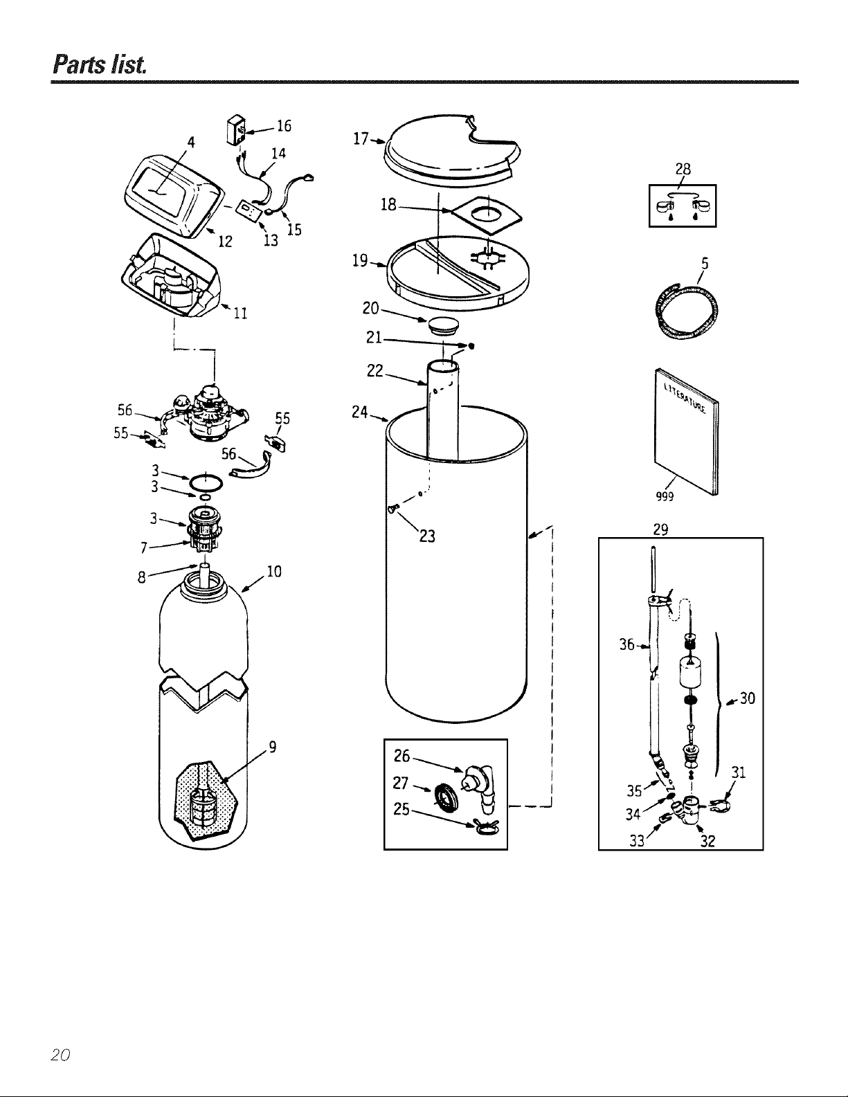
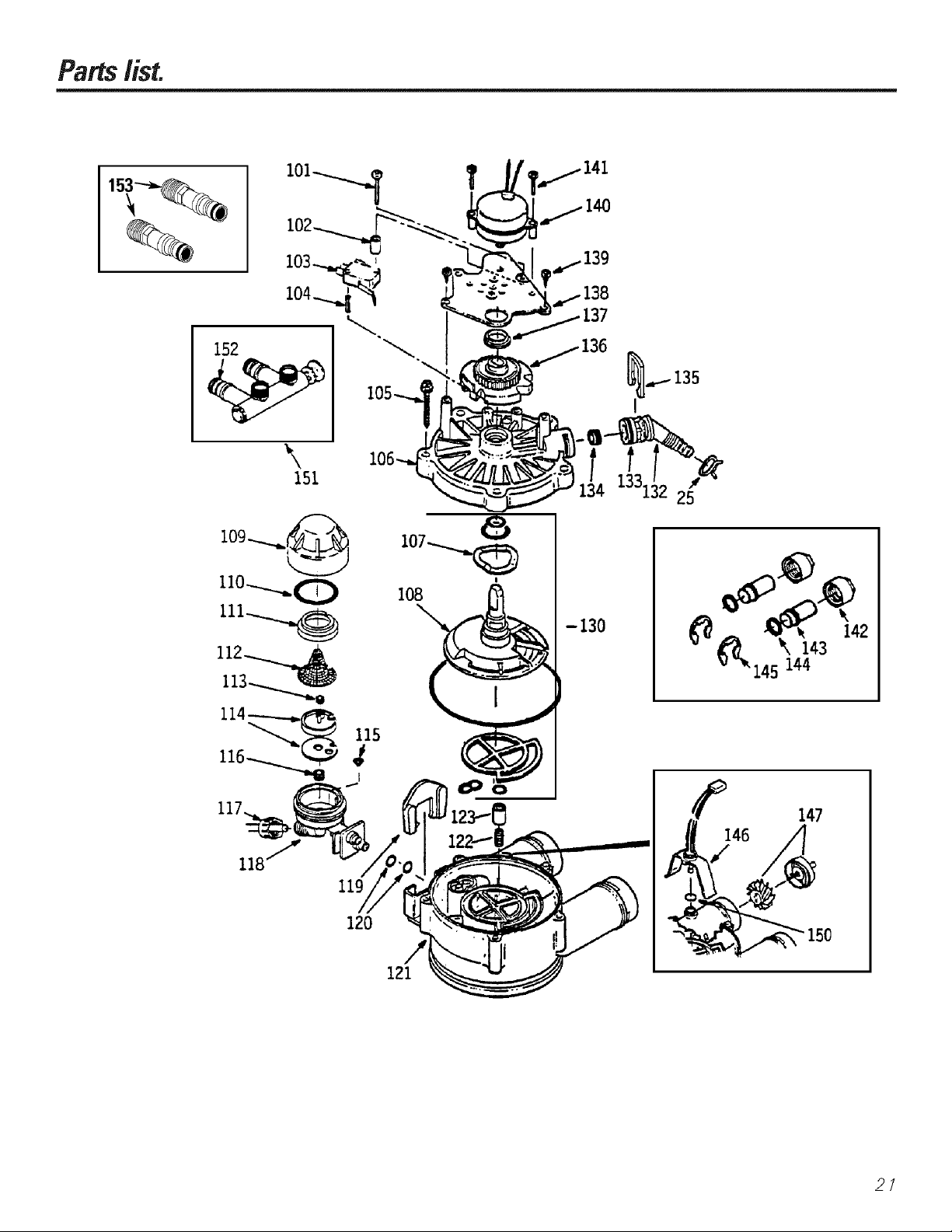
Partslist.
56_ 55
4 _ .....-.-16
28
/
18
I
56_
10
1
/If"
29
36-. _" _-30
2O
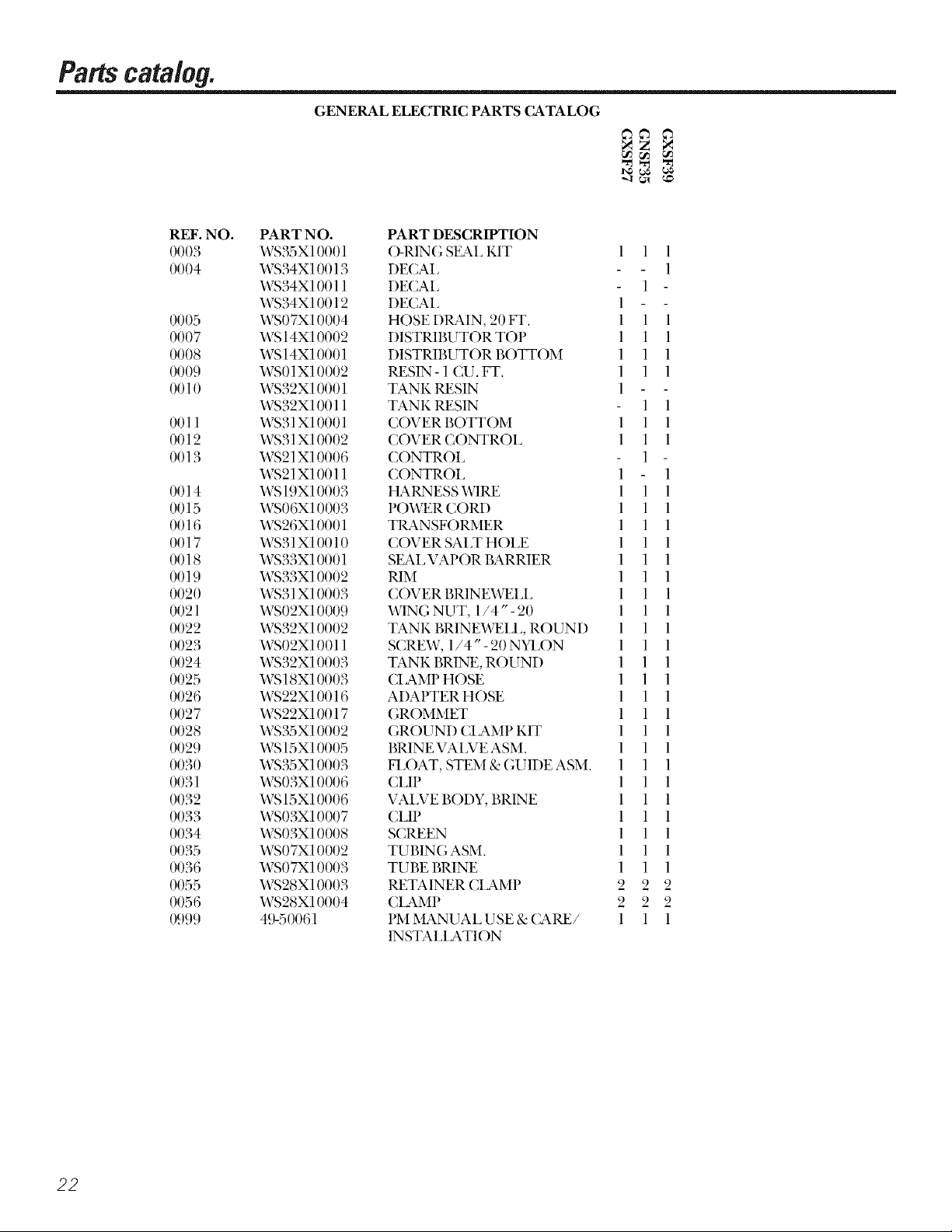
Page 21
Partslist.
152
\
151
120
-130
l
147
/
146 _
/
121
21
Page 22
Partscatalog.
REF. NO. PART NO. PART DESCRIPTION
0003 WS35X10001 ()-RINGSEA1, KIT 1 1 1
0004 WS34X10013 DECAl, 1
0005 WS07X10004 HOSEDILAIN, 20FT. 1 1 1
0007 WS14X10002 DISTRIBUTOR TOP 1 1 1
0008 WS14Xl0001 DISTRIBUTOR BOTTOM 1 1 1
0009 WS01X10002 _SIN-1 (U. FT. 1 1 1
0010 WS32X10001 TANK _SIN 1
0011 WS31X10001 COVER BOTTOM 1 1 1
0012 WS31X10002 COVERCONTRO1, 1 1 1
0013 WS21 X10006 CONTROl, 1
0014 WS19X10003 HARNESS WIRE 1 1 1
0015 WS06X10003 POWERCORD 1 1 1
0016 WS26X10001 TRANSFORMER 1 1 1
0017 WS31X10010 COVER SAI,T HOI,E 1 1 1
0018 WS33X10001 SLAI, VAPOR BARRIER 1 1 1
0019 WS33X10002 RIM 1 1 1
0020 WS31X10003 COVERBRINEWEI,I, 1 1 1
0021 WS02X10009 WING NUT, 1/4"- 20 1 1 1
0022 WS32X10002 TANK BRINEWEII,,ROUND 1 1 1
0023 WS02X10011 SCREW, 1/4"- 20 NYI,ON 1 1 1
0024 WS32X10003 TANKBRINE, R()UND 1 1 1
0025 WS18X10003 CIAMPHOSE 1 1 1
0026 WS22X10016 ADAPTER HOSE 1 1 1
0027 WS22X10017 GROMMET 1 1 1
0028 WS35X10002 GROUND (1AMPKIT 1 1 1
0029 WS15X10005 BRINEVAI,VEASM. 1 1 1
0030 WS35X10003 FIr)AT, STEM&GUIDEASM. 1 1 1
0031 WS03X10006 (I3P 1 1 1
0032 WS15X10006 VAI]VEBODY, BRINE 1 1 1
0033 WS03X10007 CI3P 1 1 1
0034 WS03X10008 SCREEN 1 1 1
0035 WS07X10002 TUBINGASM. 1 1 1
0036 WS07X10003 TUBEBRINE 1 1 1
0055 WS28X10003 P,,ETAINER CIAMP 2 2 2
0056 WS28X10004 (1AMP 2 2 2
0999 49-50061 PMMANUAI, USE&('ARE/ 1 1 1
GENERAL ELECTRIC PARTS CATALOG
WS34X10011 DECAl, 1
WS34X10012 DECAl, 1
WS32X10011 TANK_SIN 1 1
WS21X10011 ( ONTROI, 1 1
INSTAI,I ATI ON
22
Page 23
Partscata/og.
REF. NO. PART NO. PART DESCRIIVI'ION
0025 WSISXI0003 CIAMP HOSE 1 1 1
0101 WS02X10012 S(REW, #4- 24 X 1-1/8" 1 1 1
0102 WS02X10013 SPACER 1 1 1
0103 WS21X10003 S'v\ITCH 1 1 1
0104 WS03X10009 PIN EXPANSION 1 1 1
0105 WS02X10014 SCREW, #10- 14 X 2" 5 5 5
0106 WS31X10006 (OVERVAI.VE 1 1 1
0107 WS03X10010 WASHERWAVE 1 1 1
0108 WS26X10002 ROTOR&DIS(; 1 1 1
0109 WS19X10004 CAP 1 1 1
0110 WS03X10011 SL_L O-RING 1.1" X 1.4" 1 1 1
0111 WS19X10005 SUPPORT SCREEN 1 1 1
0112 WS03X10013 S(REEN 1 1 1
0113 WS22XI0020 FI_OWPIJUG, .1 GPM 1 1 1
0114 WS08X10005 GASKET, NOZZI_E/VENT 1 1 1
0115 WS03X10015 (;ONE SCREEN 1 1 1
0116 WS22X10021 PIJUG, FII,I_ FI_OW, .3 GPM 1 1 1
0117 WS03X10017 NUTFERRUI_E 1 1 1
011S WS15X10009 NOZZLE/VENTURIASM. 1 1 1
0119 WS03X10018 RETAINER 1 1 1
0120 WS03XI0019 SL_L O-RING 1/4" X 3/8" 2 2 2
0121 WS15X10010 BODYVALVE 1 1 1
0122 WS03X10020 SPRING 1 1 1
0123 WS22X10022 PLUG, DtL_klN SALT 1 1 1
0130 WS35X10005 SL_LKIT 1 1 1
0132 WS22X10023 ADAPTERDtL_klN HOSE 1 1 1
0133 WS03X10021 O-RING5/8"X13/16" 1 1 1
0134 WS03X10022 PI,UG FIfO'W, RINSE CONTROL 1 1 1
0135 WS03X10023 CIJP 1 1 1
0136 WS26X10003 CAM & GIC_kR 1 1 1
0137 WS26X10004 BL_kRIN(; 1 1 1
0138 WS26X10005 PI,_kTE MOTOR 1 1 1
0139 WS02X10015 SCREW, #6- 20 X 3/8" 2 2 2
0140 WS26X10006 MOTORASM. 1 1 1
0141 WS02X10016 SCREW, #6- 20 X 7/8" 2 2 2
0142 WS60X10001 NUTINSTALL_kTION 2 2 2
0143 WS60X10002 TUBEINSTALL_kTION 2 2 2
0144 WS60X10003 _,\D_kSHER 2 2 2
0145 WS60X10004 CI]P 2 2 2
0146 WS28X10005 HOUSING SENSOR 1 1 1
0147 WS19X10006 TURBINE & SUPPORTASM. 1 1 1
0150 WS03X10024 SL_kL, O-RING 1 1 1
0151 WS15X10012 VAI;VE BYPASS ASM. 1 1 1
0152 WS03X10025 SL_L, ()-RING 2 2 2
0153 WS60XI0006 ADAPTER 2 2 2
GENERAL ELECTRIC PARTS CATALOG
_NOTE:Codes in the Slate of Massachusetts require installation by a lit ensed
plumber and do not permit the use of the saddle valve. For installation, use
plumbing code 24&CMR of ihe Commonweahh of Massachusells.
2,7
Page 24
GEWater Softening System Warranty (ForCustomersintheUnitedStates)
For service, carl 800-GE-CARES.
All warranty service provided by our Factory Service Centers, or an authorized Customer Care_;technician.
For The Period Of: We Wit Replace:
One Year
From the date of the
original purchase
Three Years
From the date of the
original purchase
Ten Years
From the date of the
original purchase
What Is Not Covered:
Any part of tile W_lter Softening Syslem which iilils due Io a dete(::l in materials or workmanship.
During this full one-year warranty, GE xdll _llso proxide, free of charge, _lll labor _md in-home servi(e
to repla( e d_e deie( dye p_wL
The electronic monitor, if il ihils due Io a deiet:t in materials or workmanship. During dds three-year
limited warranty, you will be responsible fi)r m_y l_lbor or in-home sevvi( e ( osts.
A replacement brine tank or cabinet if eid_er ihils due 1o a de/e(:t in mat erials or workmanship.
During dds ten-year limited warranty, you _ll be responsible fi)r any labor or in-home servi( e (osts.
• Service trips to your home to teach you how to use the
product.
• Improper installation.
• Failure of the product if it is abused, misused, or used for
other than the intended purpose or used commercially.
• Filters, membranes or batteries.
• Replacement of house fuses or resetting of circuit breakers.
• Damage to the product caused by accident, fire, floods or
acts of God.
• Incidental or consequential damage caused bypossible
defects with this appliance.
This warranty is extended to the original purchaser and any succeeding owner for products purchased for home use
within the USA. In Alaska, the warranty excludes the cost of shipping or service calls to your home.
Some states do not allow the exclusion or limitation of incidental or consequential damages. This warranty gives you
specific legal rights, and you may also have other rights which vary from state to state. Toknow what your legal rights
are, consult your local or state consumer affairs office or your state's Attorney General.
Warrantor: General Electric Company.Louisville, KY 40225
24
Page 25

GEWater So#eningSystemWarranty(ForC.stomersi. Ca.adaJ
For service, call toll free 1-866-777-7627.
All warranty service provided by our Factory Service Centers or an authorized technician.
For The Period Of'. We Will Replace:
OneYear
Fromthedate of the
originalpurchase
ThreeYears
Fromthedate of the
originalpurchase
TenYears
Fromthedate of the
originalpurchase
What Is Not Covered'.
Any part of tile Water Softening System which fifils due to a detect in materials or w{)rkmanship.
During this full one-year warranty, GE ;fill also provide, free of charge, all labor and in-home sevvice
to replace the delecOxv part.
Theelectronic monitor, if it titils &_e to a delbct in materials or workmanship. During this three-year
limited warranty,y_)uwill be responsible fi)r any labor or in-home sevvice costs.
A replacement brine tank or cabine_ ifeither fails due to a detect in materials or workmanship.
During this ten-year limited warranty, you xdll be responsible for any labor or in-home sev_4_e _osts.
• Service trips to your home to teach you how to tlse the
product.
• hnproper installation.
If you have an installation problem, contact your dealer
or installer. You are responsible for providing adequate
electrical, exhausting and other connecting facilities.
I WARRANTOR IS NOT RESPONSIBI_E FOR CONSEQUENTIAI_DAMAGES. I
Warrantor: (:AM(:O INC. ]
• Replacement of house fuses or resetting of circuit
breakers.
• Failure of the produ(t if it is misused, or used for other
than the intended purpose or used (ommerdally.
• Damage to produt t caused by accident, fire, floods or acts
of God.
25
Page 26

Notes.
26
Page 27

ta section Fran aise.
S&urit_
Installation ad&tua/e ......... 29
Directives d'installation
grancheInent de la conduite
de vidange ............... 33, 34
DOballage et inspection ........ 30
Directives d'insta|lalion ..... 30-32
Directives d'installation
drape par drape ........... 33-36
OutilbNe et matOriel requis
pour l'installation ............ 31
Planification et localisation ..... 31
Proglammation du panneau
de commande ............... 35
Recommandations importantes
pour l'insmllation ............ 30
Sanitization ................. 36
SpOcifications et dimensions ...36
Instructions d' utilisation,
eonseils
Aflichages du panneau de
commande ................. 39
Diagnostics alecuxmiques ...... 41
F_limination d'un pont de sel ...38
Nettoyage de l'ensemble
gicleur et venmri ............. 38
Particulafitds ............. 39, 40
Se_wice ..................... 37
Syst6me adoucisseur d'eau..37-42
Syst6me de trigtin,ration ....... 42
Entretien et nettoyage
FJimination du fer. ........... 42
Niveau de l'entreposage
du sel et remplissage .......... 42
Conseils de d@annage . .43-45
Service aux consommateurs
(;arantie .................... 51
Liste des pi_,ces/catalogue . .46-49
Nulndros de/all@hone
importants .................... 52
27
Page 28
Vouset GE,un partenariat deservice.
IMPORTANT!
Remplissez la carte d'eme_strement du produit.
II y a deux manieres faciles d'enregistrer votre appareil!
• Parl'lnternetensaisiss'antl'adresse_.geappliances.com
• En remplissant et en exp_diant la carte d'enregisnement du produit d-incluse
Transcfivez les num#rosde mode/e et deserie ic£
,4CONSERVERSOIGNEUSEMENT
#
#
Vous les nouverez sur Fattache du r_Sse_'oir.
Agrafez /e regu de vente ou /e cheque annul6 icL
Pour obtenir le sel_ice sons garamie, i1est n_cessaire de disposer de la preuve de la date d'achat.
LISEZVOTREMANUEL
V_)usy/rouverez de nombreux conseils pour l'utilisation et 1'entretien de votre adoudssem d' emL Ces quehlues
mesures preventives w)us pem_ettront d'economiser du temps et de I'mgent pour la &nee de vie de l'appmeil.
SIVOUSAVEZBESOINDESERVICE
Vous Uouverez des solutions mix probl_mes courants que v(n]s pourriez rencontrer dans la section Avant
d'appelerun r6parateur.Et, en consultant d'abord nos Conseilsded6pannage,vous pourriez peut-t_ue_dter de
fidre appel aun rdparateur.
Sivous avez besoin de se_ice, vous savez que w)us n'avez qu'_ nous tdldphoner. Vous trouverez a la fin de ce
present manuel les numdr{_s sans flais du se_ice a la clientele.
OU
Visitez notre site Web au vvvvw.geappliances.com
28
Page 29

y y
MESURESDESECUR/TE/MPORTANTES.
USEZD'ABORDTOUTESLESDIRECTIVESAVERT/SSEMENT!
..A VERTISSEMENT! o,rvotres c,rit ,s,ivez,esdirectivesfo,mies a,s,e,r se,tma,,e,a,,
de minimiser les risques de chocs #lectriques, des d#ggts mat#riels et de
blessures graves.
S -CURIT -
• Vdrifiezet respectez lescodes de s_curit(_locaux et ceux de
l'_tat o_'_vous r_sidez. Vous devez suivre leslignes de
conduite suivantes.
• Faites attention lots de l'udlisadon de l'appareil
adoucisseur d'eau. Ne le placez pas la t6te en bas, ne le
laissezpas tomber, ne le drez pas ou ne letititespas passer
sur des aspdriff_spoinmes.
• Pour les adoudsseurs uulisanl lechlomre de sodium (sel)
pour lareg_?ndration,@)utez du sodium a l'eau. Los
personnessoumisesOdesrestrictions concernantlos
dbtes _ basedesodiumdoiventconsid&er /esodium
compl#mentairecommefaisantpartie de/a dose
quotidiennequ'dles prennent.I/est possiblede remp/acer
/echlorure de sodiumpar du ch/oruredepotassiumdans
votreI'adoucisseur.
• L'adou(isseur d'eau ti)n(lionne ave( line alimentadon
dlectrique de 24 xolts sous 60Hz seulement. Assurez-vous
d'utiliseruniquementle transformateurci-inclus.
• [_etranslbrmateurdoit etre branch,, dans une prise murale
ordinaire de 120V(3alveoles, nfisefi la terre).
• N'utilisezque du seladoucisseur d'eau propre avec une
puret(_minimale de 99,5%. Nous recommandons lesel
NU(;(;ET, PELLET Olldu selbrut SOLAR. N'utilisozpas
dnsol aI'etatsolido,onblocs,grannieonIo solservantala
fabricationde cremeglacee. Ce typede sel condent des
saletds,des s(_diments,du charbon et (Illcake qui
eIgen(treront des probl{'mes d'entrdien.
• Oardez lecouvercle de l'ofifice du sel en place sur
l'adoucisseur exceptd pour l'entreden de l'appareil ou sice
dernier est en cours de remplissage avecdu sel.
AAWRTISSEMENT:N'utilisozpasl'appareil sil'eau n'est pas
pure sur le plan microbiolo_que ou sisa qualite n'est pas
@rouv(_esansqu'elle n'ait dt_ddsinfbct_e avant ou apr_s
avoirdt_ trait(_epar l'appareil.
UNEINSTALLATIONADEQUATE
Avant d'utiliser votre adoucisseur, assurez-vous qu'il a #t# correctement install#, conform#ment aux Directives
d'instaflation.
• Installez ou enueposez l'appareil fil'abfi de temp_.ramres
int_rieures all point de coIg_lation, des intemp_fies au
aunes bpes de temps. Le gel de l'eau entrainera le bris de
l'appareil. Ne pas tenter de naiter de l'eau dent la
tempdrature est supdfieure fi100 degr_s F.
• N'installezpasl'appareil dans une zone soumise
directement a la lumiere du soleil. Une chaleur excessixe
engendrde par le soleilpeut entrainer des ddormadons ou
d'autres donunages aux (omposants non-m_talliques.
• Ette(mez lesraises a lamasse confi)rmdment aux codes el
r{'glements en cours.
• N'udlisez que de la soudureetdufluxd(_capant sans plomb
pour routes les soudures tai[es SOilSla base de soudure
ten&e, tellesque requises par les codes t6ddraux et ceux
de Fetal interest.
• L'adoucisseur exige un debit minimum de trois
gallons/minute a l'ofifice d'ennde. Lapression maximale
autofi_e est de 125psi.Siall cours de lajournde, la
pression est sup(_fieurea 80 psi, la pression au cours de la
nuit peut _?tresuperieure a lavaleur maximale. Si
ndcessaire, uulisez une valver(_ductricede pression pour
rdduire le debit.
• En presence de chlore ddpassant la proportion de 1 ppm,
il estpossible que les rdsines de l'adoucisseur seddgradent.
Sile chlore d@asse cette valeur, ilest possible que vous
constatiez une durde de vierdduite des r(_sines.Dans un tel
cas,vous pourfiez envisagerde tiure l'achat d'un systeme
de fihrage de GE.
A AVERTISSEMENT:Ddbarrassez-vousde toutcomposant
inudlis(_etdu matE'rid d'emballage apr_s l'installation.
Les petits composants restant apr_sl'installadon peuvent
constimer un danger d'dtouftbment apr_s ingestion.
VEUILLEZLIREETSUIVREATTENTIVEMENTCESMESURESDESdL-CURITE.
CONSERVEZCESDIRECTIVES
29
Page 30

Directivesd'installation.
,_kATTENTION :I1 est n6cessaire de possader une certaine experience en plombefie pour efiectuer
l'ins/allation. Si w)us n'6tes pas certain en ce qui concerne une ou plusieurs 6tapes d'installation de
l'appareil, veuillez consuher un plombier professionnel.
Deballage et inspection
Assurez-x_)us de verifier si l'appardl n'a pas e/e endommage au cours de l'expedition et si/ous les composan/s
sont pr_sems. Veuillez _galement noter si la bo_le ayant se_-i pour l'exp_dition n'a pas _t_ endommag_e.
Con/actez la ( ompagnie ay:mt eflecm_ le uansport en cas de dommage ou de perte. Le titbricant n'est pas
responsable en cas de dommages au cours du transport.
I_espetites pi_ces requises p{nn l'insmllation de l'adoucisseur sont emballees sur un canon s_)us Cellophane.
Pour _viter leur perte, gmdez-les dans leur emballage jusqu'm_ moment offelles seront requises.
Recommandations importantes pour I'installation
Veuillez pren&e connaissance du manuel m_complet. Negliger de suiwe t{)utes les consignes et r_gles peut
enuainer des blessures personnelles ou des dommages.
• Avant le debut de l'inslallation, prenez connaissance de tou/es les instructions conespondantes. Ensuite,
rOunissez tout le necessaire et 1'outillage requis p{)ur cetm operation. Une installation inconecte annule la
gmantie.
• Prenez connaissance des codes locm_x. I/installation dolt Otre confi)mm aces codes.
• Dans l'_tat du Massachusetts, il ya lieu de respecter le code de plomberie 248 CMR. Veuillez consulter votre
plombier qualifi&
• Utilisez seulement la soudure et leflux d_capant sans plomb p_)ur tousles branchements efiectu_s ;'_l'aide de
s_)udures tendres comme presoit par les codes t_ddrm_x et ceux de l'dmt considdrd.
• Branchez l'adoucisseur a la conduim d'alimentation d'em_ avantet en amontdu chm_fle-em_. NEFAITESPAS
PASSERDEL'EtlUBOUILLANTEDANS L'ADOUCISSEUR.La temperature de l'em_ qui uaverse l'appardl dolt 6tre
ini;firieure a 120 degres F.
° Manipulez l'adoudsseur avec procreation. N'inversez pas l'appardl, ne le laissez pas tomber, le tirez pas ou
ne l'ins/allez pas sur des surlimes componant des asperi/es acerees.
° I_t pression maximale d'm'rivee d'em_ est de 125 psi. Si m_cours de lajournee la pression s'etablit fi80 psi,
elle peut depasser le maximum tolere m_cours de la nuit. Si necessaire, utilisez une soupape de reduction de
pression (I/ajout d'un tel dispositif peut re&fire le debit d'eau).
3O
• I:adoudsseur ne fimctionne que s_)usune tension de 24 x_)hs, 60Hz. Assmez-x_)us de bien utiliser le
uansfi)m_ateur inclus. Assurez-vous que le transfi)m_ateur et la prise de courant soient a l'abri de 1'humidite.
° Ret;firez-vous a la section &) installerl'adoucisseurpourde plusamples delails.
AVERTISSEMENT:N'utilisez pas cet appmeil avec de l'em_ qui n'est pas microbiologiquement s&uritaire
ou de quali/d inconnue sans que l'em_ n'a pas eta ddsintectde avant ou apr6s avoir pdndUd dans
l'adoudsseur. Testez l'em_ pdriocfiquement pour vous assurer que l'appmeil timctionne de mani6re
satist_tisante.
I_esperils composants accompagnant l'appmdl qui n'ont pas ete utilises au monlage peuvent presenter
des dangers d'etotfltement. Deban'assez-vous en.
Page 31
Planifiez comment vousallez installer radoucisseur
Initialement, _ous devez d&ider comment ',pus allez brancher les myaux d'entrde el de sonie d'eau _
Fadoudsseur. E_uninez la (onduite prin( ipale d'aaTi_ de (I'eau dans Fhabitafion 15 o_1vous allez bran(her
Fappareil. Cette (onduite est-elle en (uivre, ell plastique ou en indlal gaE anisd ave( file(age? Ouelle est la
dimension de la (onduile?
_AVERTISSEMENT: N'utilisez que de la soudure et du flux ddcapant sans plomb pore 4viler lout
empoisonnemenl.
R4ti)rez-vous .l lafig. 1, Iflustrationd'une installation type utilisd, comme guide lors de voue installation
par6culi_re. Assurez-vousdedirigerI'eaud'arriv_edure(nontrait_e)dartsleraccordde/a soupapecontrOlant
I'admission d'oaua I'adouoisseur.La soupape pone les indi( aliens IN (entree)et OUT (settle).Voyez
l'illusualion ell page 32.
Ou installer I'adoucisseur
*I osmonnez 1 adou(lsseur le plus pres possfl)]e dtm egom d c'_acuanon ou de tom amre point d'& acua6on
OU tuyau de reto'tl]enlen! at (eplable.
=I1est re(ommand6 de laisser les robinets extdrieurs d0biler laeau dure (non Irail0e) aria de m('nager laeau
trait4e et le sel.
"N'installez pas l'adoucisseur 5un endroit o6 il pourrait geler. Toutdommage caus_ par le gel n'ost pas couvert
par la garantie.
N mstallez pas l adouosseur aun endron ou flre(erdaan I acres au chautib'-eau ou an robinet de iermemre
de l'arrix Oe d'eau.
*Posilionnez Fadou(isseur de telle fa(:on _'_ce que les dommages (ausds par une filite & emuelle d'eau soienl
minimis0s. Le fhbri(anI n'efie( mere pas les rdparations et lie d('dommagera pas le propridtaire ell (as de
dommages cans4s par l'eau.
=IIest ndcessaire de disposer d'Ime prise de 120 voh s p()ur y bran( her le mmsformateur ill( Ms I.a ]ongueur
du fil d'alimentafion de l'apparei] ea de l I)pi. Si ]a prise de (ouram est 41oignOe (100 pi ou moins), ufilisez
un fil de calibre 18 pour ]e bran(hemem. Assurez-vous qua Inprise de coumnt et /e Vansfonnateur soot
I'int_fieurdub_timentafin delesprot_gercentreI'humidit_.Assurez-voIlS que la prise est hers-tension afin de
pr4venir tom arr_t a( ddemel.
*Si l'appareil est installd 5 l'extdrieur, prenez mutes les dispositions n4cessaires pour xous assurer que
Fadoucisseur, les conduites serxant _'_l'installation, le cablage, etc. sore prot4g4s centre les 414meats (soleil,
pluie, xem, chaleur, froid), contamination, vandalisme, etc. comme si l'appareil mail 4td installd _'_Fimdrieur.
* Assurez-vousque/'adoucisseurno soitpas expos_directementaux rayonsdusolei/.I_achaleur du soleil peru
ddtbrmer les par6es non-mdtaHques et endommager les composanls dlectroniques.
Outil/age at materiel roquis pour 17nstallation
*Les raccords pour l'emr4e et ]a sortie de ]'eml, lesquels son( incMs avec l'adoucisseur son( des raccords de
olivre brasable de 3/4 po. Afin de maintenir un d4bit im4gral au robinet, il est recommand,5 d'ufifiser des
mymlx de I po. de diambtre pour les raccords d'enu4e et de sortie. Gmdez les m_mes dimensions oil des
dimensions sup4rieures pour les mymlx d'alimemation d'ean ;_l'emrde et ;l la sortie d'ean de l'adoucisseur.
*Pour installer l'adoucisseur, utilisez le robinet de ddrivation indus. I_erobinet de d4rivation permet d'arr,Ster
l'ean mTivam 5 l'adoucisseur aux fills d'entretien tout ell maintenant ceHe-ci dans les myaux de la
r4sidence. I_esraccords d'entr4e et de sortie mentionn4s ci-desms permet le branchemem au robinet de
d4rivation an moyen des dcrous et rondelles/pli sont in(Ms.
* Utilisez les mymlx et raccords el1 olivre, laiton oil m4tal galvanis4. Certains (:odespermettent l'utilisation des
myaux el1 plastique PVC.
oS'il est ndcessaire de disposer d'un myau d'dvacuation compl4memaire pour le robinet de vidange des
rdsec,'oirs de sel, vous pouvez le (ommander au servi(e des l)i_ces de GE ell tdldphonam au nmndro
800.626.2002.
=S'i] est n& essaire de disposer d'un twau d'4wlcuation rigide pour rester contbrme mix codes r4gissant le
plombage, vous pouvez acheter les pi_ces requises pour bran(her le myan de cuivre de 1/2 pp. de diam_?_re
oil un myan d'dvaolafion el1plastique.
=I1est ndcessaire d'avoir &_ sel d'adoucissement d'eml soils tbrme de pastilles oil de p@ites pour remplir
le r('servoir de solution saline. Voir I'Otapo8 dens les l)iroctivos d'installation £tapo par£tapo.
31
Page 32

Directivesd'installation.
Illustration d'une installation type
Eautrait6e
Prisede courantde120volts
Eaudure(nontrait6e)
Eaudure(nontraitee}vers
robinetsext6rieurs
Raccord(2)(nonfournis)
Transformateurde 24volts
Orificede
remplissagede
solutionsaline
couvercleretire
Contenantpour_ ii
solutionsaline i
Ecroud'installation (2/
Tubeencuivre,3/4 po(2)
ADMISSION
NOTE: VoirlasectionBranchements
autuyaude vidange
Robinetded6rivation
• ]]rezpourleserviceen eautrait_e
• Poussezpourd6rivation
NOTE:Lefiletagedesadaptateurs
utilis6spourI'installationsentpour
tuyauxm_lesde1 po dediam6tre.
Sidestuyauxde1pode diametre
sentrequis,nepasutiliserlestuyaux
et6crousen cuivreinclus.Achetez
unadaptateurpourtuyaude1 po
avecfiletagefemelleet raccerder
directementauxfiletagesde1po
desadaptateursutilis6spour
I'installation.
Fig. 1
Utilisezsi I'alimentationd'eauprovientdu c0t_
gauche.Incluezuned6rivationsimpleou
Eaudure(nontraitee)
CROISEMENT
3 soupapes.
EnproveoanceAll II
I'adoucisseur II 11 " I'adoucisseur
JJ
Illustration de 17nstallation optionnelle des mbinets de derivation a 3 voies
Lesadaptateurspourcetteinstallationnesontpasfournisavecradoucisseur.
Pourcommandercesadaptateurs,appelezleservicedespi_cesdeGEaunum6ro800-626-2000etdemandezlapieceportantle noWS60X10006.
Robinetde d6rivation
Eautrait6e _.._ _l sIt_rb_,l_'tnt:_;t_e_rs
- _ t _ UPRINCIPALE Eaudure(nontrait6e)
Robinetdesortie _: Robinetd'entr6e
Prisede120volts (_i_ _ _ .
_ i _ Circuitded_rivationa 3robinets
[ Pouraiimentationen eautrait_e:
[_ Transformateurde24volts / • dO_,Vro_i_srobinetsd'entr6eat
k -- -_ 'tJ.,,(_ Pourd6rivatio,,deI'eaudure(non
_ _ J _ • Fermezlesrobinetsd'entr6eet
//__ _e-_-i-T,,beencuivre, desortie
If "../'}_-_l _,. diametre3/4 • Ouvrezle robinetde d6rivation
k,._ /// ,_'_"_'_f L % po(2)
ADMISSION / (voirci-dessus)
NOTE:Lefiletagedesadaptateursutilis6spourI'instaiiationsentpourtuyauxm_lesde1pode diametre.Sidestuyauxde
1pedediametresentrequis,ne pasutiliserlestuyauxet6crousencuivreinclus.Aclletezun adaptateurpourtuyaude1po
avecfiletagefemelleetraccorderdirectementauxfiletagesde1 po desadaptateursutilis6spourI%stallation.
32
/ AdaptateurpourI'installation(2}
/
./_,,, • Fermezle rohinetded6rivation
_ , trait6e):
Ecrou(2)
Fig. 2
:°eril'f:cdetd'_
_ ,_ I'adouciss®r
CROI%MENT
Utilisezsi I'aiimentationd'eauprovientduc0te
gauche.Incluezuned6rivation
simpleoua 3 soupapes.
Page 33

Directivesd'installationetape par etape.
°Anetez l'alimentafion en _az ou en dlectrique du chaufie-eau dans le cas off ce
.... (_ . . .
dernmr son xade lorsque les (ondunes sont asse(hees.
• Arretez l'alimentation en eau aux conduites dex_mt etre coupdes et xidez les
conduites d'eau de la residence.
° OmTez les robinets d'eml chaude et floide.
1.INSTALLEZ LE CLAPET DE DI_RIVATION
° Enlever le bouchon en plastique ayant servi pour l'expedition de l'appardl ainsi
que le fil de le logement de sortie du clapet.
NOTE :Assurez-vous que la _ Turbine
turbine et son support sont '___'_ Sort
termement mont& dans le ieduclapet
logemem de sortie (Ill _[]/A [ _ _ [ Arbredeturbi,le&
clapet. Soufllez dans tP'.All I _ support
l'orifi(e du clapet et notez si
la turbine tourne libremem. .\ _, N_\\_,-_c::t
• Poussez sur le rob|net de derivation (lubrifiez les oims toriques avec la graisse fi
base de sth(one) dans les deux ot thces (Ill (lapel tel _u mdtque a la hgtn e 3A. Fig. 3B
• Mettez en position les deux grandes attaches en plastique de haul en bas, tel
...... , , , ..... VUE
(Ill lndi(/ue a la fiffure 3A et 3B.Assurez-vous (ill llssomnt bran en place. T_rez stw LATERALE
le clapet de d_nvatlon pour vous assurer qu'd est fermement mamtenu en place.
2. PLACER L'ENSEMBLE DE L'ADOUCISSEUR EN POSITION D'INSTALIATION :
o - _ ....
Assurez-vous que la sm_ace sur laquelle 1apparefl sera mstalle est bran
horizontale et sans aspO.rit&. Des objets pohhus sim6s sous le r6servoir peuvent
per(er (ehfi-d. Si nO(essaire, placer le r6sevvoir sur une plan(he de (ontre-plaqu6
dont 1epmsseur mmnnale est de 3/4 po. 1ms pla) ez des (ales sous la plan(he, le
{as _3(h6ant, pour que l'adoudsseur soil en position horizontale.
3. FAIRE LE RACCORDEMENT DES TUYAUX D'ARR1VI_E ET DE SORTIE
D'EAU DE L'ADOUCISSEUR :
_t ATTENTION: Respe(lez loules les consignes de raise en garde suivanleslors du
bran(hemenI des (0nduiles aux orifi(es (t"entr_e et de sortie Voir les figltres I el 2.
• ASSUREZA7OUS QUE L'FAU DURE (NON TRAITI_E) ARRIVANT EST DIRI(;I_E Fig. 3C
SUR L'ORIFICE D'ENTREE DU CIAPET DE IfADOUCISSEUR.
Sile debit d'eau provient du c6te gauche, utilisez un croisement illustre a la figlne 1.
St 1 mstallatum est tare Dar soudage de composants en cmwe, faire le soudage
tendre avant de raccorc_er les tuyaux au clapet de denvatmn. 141 ( haleur du
chahnneau endonnnagerait les composants en plasfique.
• I_ors de la ro/afion des raccords de myaux dans les raccords en plasfique, faites
attention de ne pas foirer le filetage.
• U filisez un uomposa sin tousles filetages ex/ernes des m}_mx.
° Faire un support pour la m}vtuterie d'mTiv_e et de sortie d'eau (supports a
myaux) afro d'all_ger le poids irnpos_ aux raccords de rob|nets. Fig. 4
4. RACCORDEZ ET FAITES FONCTIONNER LE TUYAU DE VIDANGE :
° Utilisez le mvau de vidange fourni (inclus et dont la longueur est de 20 pi.) et le
brancher au_raccord (Ill r_)binet de x4dange. Min d'em_acher la press|on de l'eau
de d_3brancher le myau, utilisez une attat_he pour le maintenir eft place.
I_ocahsez 1aulie extremtte du tuvau et placez-le a un orifice de xqdange appropne
(onhce de xadange du plan(her, resevvon, bac uuhse pour la vt(bmge de 1 eau de
laveuse, etc.) qm aboutlt a 1egout. Venfiez quels sont les codes locaux et /
respectez-les.
IMPORTANT :Sititle longateur suppl(_memaire de Iuyau de x5(tangeestne(essaire, vous
pouvez (ommander le myau au sem(e des prates (,E au no 8004!26-J)02. L adouctsseur ne
peut fonctionner sil'eau ne peut &lre_vacu_edu myau au cours des r_g_n_ratiorts.
°Attachez ou fixez le mvau en place _'_l'_fide d'un fil au tx)int de vidam_e. 141haute
Dl'eSslOn de 1 eall entialnela le Fell'at[ et des (a/des de llncaffe l'aDldes all COllls des
r,hg_3n_3rauons.De plus, m_nagez un espace minimum de 1-1/2 po. entre
I extre_mte du tuyau et du pomt de wdange. Un tel espa(e empeche 1eau d egout
d etre s@honnee a 1mteneur de 1 adoucBseur en (Tasde re*oulement de 1egout.
o _ ......
S fl est necessmre de soulever le mvau de xadange pour auemdre le p()mt de
• • % °
vMange, ne le soulevez pas &une hauteur sup_neure ai8 pL par rapport au
planc_er. I_efifit de le thire peut (auser une (ontre-pression risquant de r6duire
Faspiration de la solution saline au cours des regenerations.
Fig. 3A
Lejointtoriquen'est
plac6quedansla
rainureexterieure.
L'attacheseplacedarts
la rainureint@ieure(voir
ci-dessous).
VIDANGEAUSOL
Corpsduclapet,
entreeou sortie
t SO_RTIE
ENTREE
_qau de
vidange
Attache
Sortie
:lapetded@ivation
_OYE:Lefiletagedesadaptateurs
utiHs@pourb chpetded@ivation
sontpourtuyauxm_lesdeI pode
diam@e.SidestuyauxdeI pode
diametresontrequis,nepasutilber
destuyauxet@rousencuivreindus.
Achetezunadaptateurpourtuyaude
1poavecfibtagefemelbetraccorder
@ectemeotauxfibtagesde1po.
Attache
X VUE,_
Clapetded@ivation(poussez
completementa I'interieur}
L'EXmEMITE
Toumerle clapetde
d@ivationsur180
degr6spourle
branchera laconduite
setrouvantall niveau
dusol
'JL
TUYAUDERKOULEMENT
Espacede l_Apo
Espacedel_po. 33
Page 34

Directivesd'insta//ationetapeparetape.
4A.BRANCHEMENTD'UNTUYAUDEVIDANGERIGIDE Fig. 4A FiletageNPTU4po
l'extrdmitd barbelde (luraccord (levi(langecomme illustrd5 la figure 4A.Faire toumer leraccord (levidange Barbel6es tubeencuivre
*Pouraria}ter un tuyan de xidange etatui__e_'d'adoutisseur,attilisezatnes(ie_'tmdtaak,;}ourtouper -_7,_ _'/ v.."_''P 1/2po.0.D.
de tellemanibre (latelalame de.lascie soiidloigride,dtt logelnent dtt clapet pour_prdxenirtout domuiaue,5 ,,,,(; (nonfourni)
celum. Achetez un raccttrd a corn nresston (flletagefemelle(le 1/4 po.x 1/2 pit.pour le robe ().D.) et la i"L-
myanterie re(luisede xotre qaiincaillier.
5.INSTALLATIONDESRACCORDS DEDEBORDEMENTDU RESERVOIR DE SOLUTION SALINE A
ETLATUYAUTERIE
*Insg.rezl'oeilletetacaoutdtouc dins l'orifi(e de3/4 po. de diam(tre sm la pan_ilv_t_raledu rdsevvoircomme CoupezI'extr_mito
indiqud 5lafigure 5. barbel6edu
oPoussezl'extrdmitd du coude de l'adaptateur du tuyau dins l'oeillet comme inditlud5la figatre5. raccorddevidange Raccorddecompression
"Eixeztitle long_letlide tuvatl (utilisezle restede ttlVande l'dt_q)e4 aucoude de l'adnpt_teur (hittlvan. OID.{nonfoum[)
l_tilisezune aktachede myanpour tuaintetfir te demier etaplate. " Fig. 5
*Placerl'antre extrdmit_du tuyan an point (le fidange. N'ELEVEZPASce re)an5 une hauteur supdrieure mi
coude sty le t_servoir (lesohition saline.
IIVIPORTANT:NE FIXEZPAS LETUYAU DE DEBORDEMENTAUTUYAU DEVIDANGE. \ (
NOTE : Le robede vi(l_,igene sert (latepout des besoins de sd(uritd.Sile rdsetxoil (lesolution saline se remplit
ex(essi_ement(l'eau, l'excd(lent seradirigdsur)'orifi(e de vidange;
6.INSTALLATIOND'ATFACHESDE MISEA LAMASSEET CABLAGE
,A DANGER: i_ef_li[denepasuiettre5]auiasselefil servant5ceteftetpeat[canserdeschotsd]e(triques' _ tuyau
"Sila tuyauterie est en metal, et atin (le maintenir une continuit&demlse itlamasse _lectrique pour ]a _ Attachedutuyau
tuyantefie d'ean fifo)tie,montez leoattaches de raise_'tlamasseincluses _'tl'a ? ?areilcomme indiqud 5 la
f]g_lre13.Assurez_vous{latees tuyanx setroal,,,atatsoilsleoattachessont prt)pres af it d'assurer aliabon
c()ntactdlectfi(lue. Oeilleten Nepasbrancherstirle
7.RINCAGEDESTUYAUX,ELIMINATION DELAIR DEL'ADOUCISSEUR ET ESSAIDE tuyaudevidange.
L'INSTALLATION POUR DETECTER LESFUITESD'EAU :
,_ ATTENTION :Pour _vltertoutdommagecans_par l'ean oulapress)on de Fairpouvant affecter leo Tu'./audevidange
composantsinternes de l'adoudsseur, assurez-vousdesuivre leo_tapessuivantes dins l'ordre exact, pourd6bordement
A. Ouw'ez compl_tement 2rob)nets d'ean traiteefro)de ilproximit_ de l'adoucisseur.
B.Placez lerob)net de d6rivation sur laposition ,,bypass ,,(derivation)en poussant l'axe versl'int6rieur.
C.Ouvrez complbtement lerob)net prindpal d'alimentatlon en ean de lar6sidence. Notezs'il existeun d6blt
continu des deux rob)nets qui ont 6t6ouvertsitl'6tape A ci-dessus. Fig. 6
LIESROBINETS D'ALIMENTATION EN FAUTRAITEE SUR LAPOSITION OUVERTE. d'entrb_e
Tirez LENTEMENT ou faites gfisserla t'Nedu rob)net (out) (versl'exterie_) verslaposition <,service>_
D.Placezle rob)net ded_rivatlon sur la position _service _,(_rvice) EXACTEMENTcomme suit. GARDEZ _]_-'2"w_ _v
(service)en faisant plusieurs pauses afin de permettre g l'adoudsseur d'etre lentement ntis souspress)on, ttache(2)
E.Apl_s environ 3nfinutes, ouvrez un rob)net d'ean HOT (bouillante)pendant 1minute oujusqu'_ice que l'a ,,lq_ "_._, t
caoutchouc
1/4po.tubeNPTx1/2po.
Verslerob)oct
plusieursminutes ou jusqu'5 ce (latel'ean (levienneclaire.
F.Fermez tous les robi_ets, miseala
O.V_rlfiezles travaux de plomberie que vous avezeffectu_s pour d_tecter toute fuite. R_parez celles-d
imm_diatement lecas _ch_antet assurez-vousderespecter les notes de raise en garde pr_cedentes.
ait&re&vacu&puisle fermer. NOTE : Sil'ean parait trouble oatsile gofltest sald,(Otltitltlezpendant ___ tt_
H.Mettez en marche l'alimentation engazou en _lectricitepour le chanffeean. Allumezla flamme veilleuse
lecas _ch_ant. Enprovenancedu
8.AJOUTDEL'EAUETDU SELAU RI_SERVOIRDESOLUTIONSALINE:
•Levezlerouvercle du rdsetvoirsolution saline._joutez emiron 24gallons d'eau (lans lerdserroir. N'eta a.joutezpas dins le contetaant pour solution saline.
RemDhssezlereservoir a_e( leotoduttNL(,(,ET (pepltes) t EILET (pastilles)ou a',e( le belbrat OOtliad!)u(lsseulSOLARdont l,tputete dolt ette caale ou surtcneute
a99,J);. N utihsez pasdu selen roches, eu bl!_:s _ranule ou lesel sea ant a 1',tconfection de creme _lacee ou encore du selcontenant des additlfSservant a el)miner le
fer, ( 5l'exception du sel de mar(lue Diamond Crystal Red.Out). La capacitdd'entreposage du s_lestd'em4ron 200lbs. Gardezlecomercle de l'oritice du seletaplace
sur l'adoucisseur sauf au (:()tars(le l'entretien (lel'appareil ou lt)rstluele tempi)osagedu sela lieu.
NOTE: Sil'adoucisseur estinstallddins amsous-solhumi(le ou tout autre endroit dgalement hum)de, ilest prdt_rable (le remplh-lereservoir avecmoins de sel etplus
frequenmient. Une (luanfitd de 8!)5100lbs(le sel durera phasieursmoisetatbnctioti de 1',tduretd de l'eau, (lithombre de personnes dartslafhmilleet (lumo(l_le
(l'a(lotacisseur(l'eau.
9.BRANCttEMENTA LASOURCE D'ALIMENTATIONI_LECTRIQUE:
•Si le c;lble(lit transfilmaateurn'est pasrisible _'tl'arri+re (le l'appareil, retirer le couverde. NE TIREZPASSUR LE C\I',I£ OU NE LE Dt_.BI_NCHEZ I'AS.D_calisezle
long filcomporpantdes cotmecteurs etaU _il'tme des extrdmit_s.Faitespasser lefilau trivets (litlogement (litpatmean de comman(le. Remettez le c(_uvercleetaplace.
•Fixezleoconnecteurs etaU max2fisdu transtbmaateur etsetaez celles<i. Eustfite,bmnchez le transti)rmateur darts1',tpri_ de courant.
•L'ad!)ucisseurfi)nctionne sous tree tension de 24w_lts60Hz. Le transtormateur inclus _'tl'appareil rd(hfitlecourant (le 120u11tsCAstan(lar(1_'_24u_lts.Ne branchez le
transformateur que dins une prise de 120volts.Assurez-vous(lue 1',tprise estetapermanence soustension (le titq)n _ ce (tuel'alimenpation dlectfique ne soitpas cotpde
par etTeur.
10.PROGRAMMATION DU PANNFAU DE COMMANDE:
•Rdf(:rez-vous5 la section Progranamation du panneau de commande.
rob)netdesortie
masse
U
34
Page 35

Programmation du panneau de commande
PROGRAMMATION DU PANNEAU DE COMMANDE
REQUIS ;ll'installafion et apr_?sune longue panne de tornant.
NOTES :
• I,ORSQU E I,E TIL_kNSFORMATEUR EST B1L_NCH(< DANS
UNE PRISE DE COUtL_kNT (voyez l'dtape 9), l'aflichage 12:00
AM (clignotent) et PRESENT TIME (Temps acmel) apparait
dans la ten_?/re. ProgTamnmz panneau de commande comme
indiqud d-dessous. Si la 16gende SR-- cfignote, utilisez le bouton
UP (+) _ (Vers le haut) pour progTmnmer le code SR comme
suit : SR35 pour (;NSF35, SR31 pour C,XSF39, ou SR22 pour
GXSF27. Si vous avez ddpassd le bon code, ufilisez le bouton
DOWN (-) _. Ensuite, appuyez sur le bouton SEI,ECT
(S_?lection) et progTmnmez le pannem_ de commande.
• Un _<bip - se tait entencke lorsque vous appuyez sur des boumns
pour la pro_ammadon du panneau de commande. Un bip
indique un changement clans l'attichage N1 panneau de
commande. Des bips rdp414s signifient que le panneau de
commande n'accepte pas un changement provenant du bouton
sur lequel vous venez d'apptger et dans ce cas, v{)usdevez udliser
un atme bouton.
• Pour programmer le pannem_ de commande, vous devez ufiliser
les bou/ons UP (+) /o\, (Vers le hmlt), DOWN (-) _g (Vers le
bas) et SELECT (Sdlection).
AFFICHAGEDEL'HEUREACTUELLE ] ,_,,_y[ [,q,M__
NOTE :Si l'attichage PRESENT TIME (Heure Acmelle) n'apparait
pas dans la fbn_tre, appuyez sur lebouton SELECT (S41ecdonnez)
jusqu'_'t ce que cet attichage se tasse.
1.Appuyez sur lebouton UP (+) !& (Haut) ou DOWN (-) _ (Bas)
pour l'attichage. Le bouton UP (Haut) tait avancer l'attichage, le
bouton DOWN (Bas) fair reculer l'attichage.
Sil'heure acmelle se uouve enue midi et minuit, assurez-vous que
PM figme dans 1affichage ,=,_,_,_l_ {O!fF'_,_
NOTE :Chaque enti)ncement des boutons UP (+) ?b_(Haut) ou
DOWN (-) 3g (Bas) modifie l'heure d'une minute. I,e maintien (h_
bouton enti)ncd modifie l'heure _'t_aison de 32 minutes chaque
seconde _=_,_1"_,'/,...._"_l_'__L_l,_d"
2. I,)rsque l'heure acmelle s'afliche, appuyez sur SET
(S(qecdonnez) pour latiger. Sil'heure acmelle se uouve entre
minuit et micfi, assurez-vous que AM figure dans l'affichage.
AFFICHAGE DE LA DURETI_ DE L'EAU ] I
NOTE :Si le chittie 15 (rdglage standard _ _-_f
fhit en usine) et le terme HARDNESS
(Duretd) n'apparaissent pas dans l'attichage, appuyez sur SELECT
(Sdlectionnez)jusqu'5 ce que cet attichage se tasse.
1.Appuyez sur lebouton UP (+) /oZ (Haut) ou DOWN (-) _]
(Bas) pour r4gler la (hnet4 de l'eau dm_s la ten{-tre d'attichage.
Le bouton DOWN (-) W (Bas) tait descendre l'attichage sur 1.
Le bouton UP (+) /& (Haut) passe l'attichage sur la valeur
maximale.
NOTE : Chaque entoncement du boulon modifie l'_dtichagv de 1
unil4 enue 1et 25. Au dessus de 25, l'attichagv est modifi4 de 5 unil4s
a la Ibis (25, 30, 35, etc.). Demainden d'un boulon entbnc4 modifie
les chitties deux Ibis par seconde.
Bouton
UP(+1
(Haut}
Bouton
DOWN(-)
(Bas}
Fen6tre /
d'affichage @
L SmartWater SoftenerSystem
BoutonTOUCHou HOLD(Toucheroutenir)
Bouto. SELECT(S61ectionner}
2. I,orsque la xvdeurde la &nelO de l'eau apparait, appuyez sur
SELECT pour la figvr.
NOTE : S'il y a presence de fer dans l'eau traitee, vous devrez
accroitre le reglage de duret_ de 5 unit_s pour chaque 1 ppm de
fer dans cette can.
Vous pouvez obtenir le hombre de ,grainspar gallon (gpg) d'eau
d'tm laboramire effectuant des analyses d'eau ou encore,
appelez et demandez/_ votre service local des eaux si vous
recevez votre eau des autorites munidpales ou appdez le GE
Answer Center ®et demandez leur tree trousse de verification
de la durete de l'ean. Sile resultat indique que la durete est
evaluee en parties par million (ppm), divisez simplement la
valeur par 17,1 pour obtenir l'equivalent en nombre de grains
par gallon.
PROGRAMblATION DE UHEURE DE REGENERATION
(D£BUT)
NOTE : Le message RECtL__R(;E TIME (Heine de recharge) et
l'attichage 2:00 AM (2 heures du madn) (ROg]agestandard tidt
en usine) cbivenI apparahre clans la ten@e. I,'heu_e est
appropfide pour commencer la rdgx)ndradon (qui se tel_nine
apl_?senxfiron2 heures) pour la plupart des rdsidences _)tant
donnd que l'eau n'est pas utilisde dans cette p&Jode. I_'EAU
DURE (non uaitde) est ddfivde vers les robinets de la rdsidence
an cours de la rdgx)ndration.
Siaueune modification n'est ndcessalre, passez a l'_tape 2. Pour
modifier l'heure du ddbut de la rdgx)ndration, suixwzles
indications de l'dtape 1.
1.Appuyez sur le bouton UP (+) _. CHant) ou DOWN (-) W
(Bas) pour progTammer l'heure de dabut de la rdg&_)radon
ddsirde.
NOTE:ChaqueentkmcementduboutonUP (+) _ (Haul) ou
DOWN (-) W (Bas) modifie l'heure de une heure. Le maintien
des boutons entkmcds modifie l'heu_ e deux Ibis chaque
seconde.
2.Appu}ez sur le bouton SEX,ECTune Soisde _, F"I _"_.,_
I)hls. _"_er,_
t-- ' LdLd
Assmez-vous d'obserxer l'attichage AM ou PM comme vous
l'avez fait lots de la progTammation cDl'heure dujour.
La ten@e aftiche l'heure acmelle el le message RECHARGE
TONIGHT (Recha_gez cette nui0.
?5
Page 36

Directivesd'installationetapepar etape.
Methode de sanitization
PourterminerI'installation,suivezla m6thodesuivante:
Toutes les precautions out dtd prises en usine pour s'assurer que Fad(n]dsseur est propre et confi)rme mix (onditions d'h}giane.
I,es ma/drim]x ufilisds p(tur la titbricafion de l'appareil n'iittbcteront ni ne contmnineront voue eat] et ne cm]seront pas de
fi)rnla/ion de bactdries ou leur ddvdoppement. Cependam, il est possible que des bactdries pdnbUent dans l'adoudsseur m] c(turs
de 1'expddi/ion, 1'emreposage, l'insmllation et l'utilisation. C' est pour cette raison que nous suggdrons de pro(alder a une
sanitiza/ion lors de l'installa/ion.
NOTE:ta sanitizationestrecommandeeparla Water QualityAssociation(associationchargeede fairerespecterlaqualitedeI'eau)pour
assurerla desinfection.
[_ Assurez-vous d'acc()mplir routes les drapes de l'installation, la progrmnmation du panneau de connnande incluse.
[_] _ eisez emai (m 3/4 on(es d Eat] deJmel donmsuque ((m(enu eea ,%25/v (( h)rox, Lin( o, BoPeep, White Sail, Eagle, et(.) dans
le contenant de solution saline. Voir le s(hdnla ala page 32.
[3_IMPORTANT:Appuyez sur le bouton TOUCH/HOLD(Appuyez/Maintenez) et maintene>le enfon(d pendant 3 se( ondes pour
ddclencher tree rdgdndmtion innnddiate. I_e message RechargeNow(Rechargez maintenant) connnence fi clignoter. L Eau de
Javel est aspirde dans l'adoucisseur d'eau.
[_]Si apr_s avoir suivi (retie procddure, l'eau provenam des robinets de l'habitation atm goQt said ou est Kg_rement color,Se, ceci
est (,lt]se p,lt la mauei e pi esei_ am e pmx enam (It]iesei_(m de i esme. Om_ ez les iobmets d eat] h olde et laissez ( oulei l edu
pendam quelques minutes ou jusqu'5 (reque l'eau soil claire.
NOTE:Une _)is le processus de rdgdndrafion pour sanifization terminal, voUe eau FROIDEadff_compl(tement uaitde. Cependant,
voue chaldt(-eau est rempli d'eau (hHe (non traiff_e) et au fin et _'tmesure que l'eau est consonmV_e, celle-ci est remplacde par de
l'eau uaiff_e et l'eau bouillante ainsi que le m(qange eau bouillante/eau fioide sera composd complbtement d'eau uaitde. Si vous
souhaitez imm(_(fiatement avoir de l'eau traiff_e, videz le chauffe-eaujusqu'¢t ceque l'eau soit fioide apr& leprocessus de
r_gdn_radon.
A AVERTISSEMENT:Si vousvidez le (hauite-eau, faites tr(s attemi(m (ar l'eau bouillame peut (auser des brt_lures. (_teignez le
chm]fli_-em] ax:tilt de le xider.
SPI_CIHCATIONS/DIMENSIONS
Capacitd nominale*
Quantitd de rdsine de haute capacitd (lbs/pixn)
Dimensionn0minaleduresem)irderesine(diameu'eenp0m>sxpisnbe)
l)dbit de sel_ice (gpm)
l)uretd m_edmale de l'eau d'alimentation (,.-,l,.-,)
O" 10"
Fer mmdmal contenu dartsl'eau traitde (ppm)**
Iimites de pression d'eau (min.m_e<.psi)
Chutedepression5lavaleurnominaleduddbitdeservice(psN)
Tempdrature mmdmale de l'eau (degTdSF.)
l)dbit minimal de l'eau d'alimentation (gpm)
GXSF27 GNSF35 GXSF39
(Voyezl'dtiquettedescapacitdssimdesurl'adoucisseur)
36,4/,7 48,4/,93 52,5/1
8 x 40 9 x 40 9 x 40
(VoFzl'dtiquettedescapacitdssitu@sur l'adoucisseur)
100 100 100
5 6 8
20-125 20-125 20-125
15 15 15
120 120 120
3 3 3
u_381'O
1 t
48 _' t P() | _18 I ,I I>() _ /
ti ]'tPO 4(_I '21>0
l)dbit (Illcyclede rdgdndration (gpm)
Remplissage (ddbit all rdservoir de solution saline)
lm_ageavecsohltion saline -!
l>,incage,,de la solution saline_,_.m l'orifice(I)dbitverSde
Refibulement
I[
vi(tanoe_
Rinqage rapide .._
,3 ,3 ,3
,19 ,20 ,20
,12 ,16 ,16
1,8 2,0 2,0
1,8 2,0 2,0
1.c s?s@me esl (_'(mtbrme aux n()rmes 10 WQA S-100 pour les capadlds spddtiques tels quc vdritK'es et conlh'mdes par les donndes laisan( suite aux essais.
* l.cs essais on/Old lhits en udlisan( le chh)mre de sodium pour paslilles (_'()mineagcnt de r,Sg(-ndra(i( m.
*:'_la quanlit,5 de R'r dlimind peut varie!"avcc les conditi()ns existanles. Cet(e dlimination est amdli()rde en ufilisan( les pr()duits Diam()nd Crystal, Red.()ul
<)uSuper Iron Out. V()ir la section Himination du Nr contonu dons I'eau.
36
Page 37
Ausuiet dusystemeadoucisseurd'eau.
Service
I,orsque le systbme adoudsseur d' eau fimrnit de l'era1 traitde, il est appeld <<Seixice -. Dans celte tbncfion,
Feau dure (non traitde} en provenance de la conduite principale de la rdsidence s'4coule darts le syst_?me
adoucisseur d'emx. ]\ l'imdrieur &l rdservoir de rdsine se lrouve un <<lit - t onstim_ par des milliers de grains de
rasine-plastique de petites dimensions. Lorsque l'emx &ire (lion mtitde) passe an travers &l _<lit-, chaque
grain attire et garde les min4rmxx solides. Celte op4ration ea appel4e un 4change d'ions, comparable a un
aimam qui attirerait el garderait des paniofles m4talliques. 12eml qui lie conlient pas de min4raux &lrs (eau
traitde) s'& oule &l syst_me adoucisseur d'ean vers les con&lites de la rdsidence.
Apr& un cert>fin temps, les grains de r4sine sent recouverts de min4rmxx durs. Ils doivent doric atre neltw4s.
Ce nem/yage est appel4 r4g4n4ration ou recharge. Celte r4gdn4ration d4bute _'_2 heures &xmatin (r4glage thit
ell usine) pal le syst_?mede comr61e de l'adoucisseur et se tilit el1 cinq 4tapes ou cycles. Ces ()'des sent
REMPUSSAGE,Tga/rEMENrEJVSOWnONSAUNEraN€aGEOEM SOWT/ONSAUNE,REFOUtEMENTet
R/N_AGERAP/D£
Derivation automatique de l'eau dure (non traitee) au tours de la regeneration
Pour lesbesoinsurgems, l'eau dure (nor_uait_e) est Cependant,vousdevriez_viter d_tiliserdeI'eau
disponible d;ms la r4sidenxe pendant les xyxlesde BOUILLANTE6tant donn6 que le chauffe-eau so romplira
r_g_n(_ration, avecde/'eau dure(nontraitOe).
Remplissage
I_esel dissout dans l'ean ea appeK solution saline. Ceue solution est requise pour enlever les min4mux durs
des grains de r4sine. Pour tiJbriquer la sohltion saline, l'eau s'4coule dans la zone d'emreposage du sel au cours
du remplissage tel qu'indiqu4.
ravage avec solution saline
Au (;ours de ce lax'age, 1;isolution se ddplace du (omemmt d'entreposage du sel el se rend dans le rdservoir de
rdsine. I_a solution saline et l'agent de nettoyage requis pour enlever les mindraux &lrs des grains de rdsine.
Ces min4ranx el la sohltion sore 4vaol4s dans l'orifice de vidange.
I_egicleur et le xemuri crdem une su( cion d4placant la solution saline el1maimenam un ddbit trOs lent afin
d'assurer le meilleur neltoyage axe( le minimum de sel
RinGagede/a solution saline
Apr_s qu'une quanlitd prd-mesurde de sohltion saline est ulilisde, le Clalxelse terme. I_'eau (ominue 5 couler
dans le m0me sens except4 que le d4bit de solution saline lie sepro&lit phls. I_esmin4raux &its el la solution
saline sore dvaolds du rdsel_'oir de rdsine vers l'orifice de vidange.
Refoulement
Au (ours du refi/ulement, l'ean se d4place a traversdu rdsevvoir de r4sine axe( un ddbit rapide et rinse le ter
qui s'est ac( umuld, les salelds el les sddimems du <<lit ,,de rdsine el se dirige ensuite vers l'orifice de vidange.
Ringage rapide
Le refonlemem estsuM d'un ddbit rapide de l'eau autraversd'xm r4seI_,oir der4sine. Ce rin<age rapide rin(e
lasolution saline du fired du rOser',oir el re(onditionne le dit ,>de rOsine.
Aprt's le q,(le de rincage rapide, le syst_me adou( isseur d'eau repasse dans la tim( lion service de l'eau mfitde.
,77
Page 38

Au sujet du syst#meadoucisseurd'eau.
_'limination d'un pont de sel
Parlbis, une (rofite solide ou pont de sel se fi)rme dans la zone
d'enueposage &l se]. Habialellement, cette crofite est cmls4e par une
humidit(' 4lev4e ou l'utilisation d'un type de sel inflppropri4. Siun
tel pont se torme, un espace vide est cr44 enue l'eml el le sel. En
cons4quence, le sel ne se dissom pas dans l'ean pour ihire une solution
saline.
Sila solution saline contient beau( oup de sel, il est diflicile de
d4terminer si un pont de sel s'est tr44. Au sommet, le sel est iiiable
mais le pont se trouve en dessous. I.a m4d_ode suivame est la
meilleure pour savoir si cela est le cas.
I_esel devrafl _tre fliable jusqu'an fired &l r&ervoir. ]\ l'aide d'un
manche de balai ou d'un outil similaire, le pousser en prenam tomes
precautions dans le sel en hfi imprimant un mouvemem du hant
jusqu'en bas. Si l'outil rencontre un objet &lr (assurez-vous qu'il ne
s'agit pas &l fired ou des pmpis lat('rales &l r4servoir), il est probable
qu'il s'agh d'un pont de sel. A l'aide de cet outil, cassez le pont. Ne
pilonnez/*as les patois &l r('servoir.
Si]e pont a 414%rm4 a la suite de l'utilisation d'un mmwais b'pe de
sel, retire>le puis remplissez le r4seiwoir avec &l sel en pastilles ou en
p4pites exchlsivement. Dans des zones humides, il est pr('fKrab]e de
iifire le plein avec moins de se]mais phls ii4quemment.
1po. 2 po.
Repere
Manche
debaJal"-_'
PoussezI'outil dansle pont afin de le
Casser
Pontde
Niveau de
I'eau
Nettoyage de I'ensemble gicleur et venturi
Pour fonctionner correctement, le syst_me adoucisseur d'eau requiert tin
gicleur et un venturi propres.Au __nns de la r_g_n_ration, ce petit
ensemble assure la succion pour transporter la solution saline de la
zone d'entreposage (h_sel au reservoir de resine. En cas de bouchage
pro du sable ou des salel4s, etc., le systeme adoudsseur d'em_ ne
fimctionnera pas et vous n'mlrez que de l'em_ dure (non mtit4e).
Pour acc_.der m_gicleur et m_venmri, retirez le couvercle du syslc)me
adoucisseur d'emL Assurez-v_)us que le sys/t)me est en mode Se_-ice
(le gicleur et le venmri ne sont pas soumis a la pression de l'em]), En
tenant le logement du gicleur et ch_venmri avec une main, retirez le
couvercle. Soulevez le support de la grille et la grille elle-meme et
ensuite le gicleur et le venmri. Nettoyez ces pieces avec de l'em_
chaude. Si n4cessaire utilisez une petite br(_sse pc)ur enlever les
cKp6ts de ter ou les salelOs. V(hifiez et nettoyez (_galement lejoint.
NOTE: ( ertains mod(les sont equipes d'un petit bouchon de contr61e
de d_bit sim_ (hns l'ensemble gicleur/venmri et/_)u d'une petite
grille en torme de c6ne dans le logement. Assurez-v_ms de les verifier
et de les nettoyer si voue module en est dot&
Replacez soigneusement tous ces composants dans le bon ordre.
Lubrifiez Kg(hement les joints toriques avec de la graisse m_silicone
)u de la vaseline et remettez-les en place. InMallezet serrez le
couverclea la mainseulement.Ne serrezpasexcessivementle couvercle
oule Iogement.
Couvercie
Joint torique _
Supportdelagrille_
Grille _ &
_gouchonde
contrQleded6bit _ _'
Gicleur& Venturi
!
Logement du gicleur et
du venturi
i
38
IMPORTANT: Assurez-vous que los petits trous du joh?t
correspondent _ ceux du Iogement dugicleur et du venturi.
* Montez avec le cStfi numfirot# en haut, le cSt# concave
en bas.
Page 39

Affichages en utilisation normale
I.ors de l'utilisation normale, 1'heure acmelle ainsi que les termes AM ou PM sent aflich_s clans la tenO.ue.
I,orsque l'ordinateur ddtermine qu'une rdgdn&ation est requise, le message RECHARGETONIGHT(Rechmgez
cette nuit) commence a clignoter dans la tbn&re avec l'heure acmelle. RECHARGETONIGHT(Rechmgez cette
nuit) 3-j2- clignomjusqu'a l'heure o_'_la prochaine r4g4n&afion doit ax_)irlieu. I?aflichage change pour
dexvnir RECHARGENOW (Rechmgez maintenant) qui clignote jusqu'a ce que la rOg&_&afion prend fin.
Particularites : Commandespour recharge optionnelle
P_wlbis, il peut 0.Ire souhaitable ou vous pouvez
proc&ler a une r4g&l&ation (redlarge). Voicideux
exemples:
• Vous avez utilis_ plus d'eau que de coutume
(inxdtds, lavage suppldmentaire, etc.) et vous O.tesfi
COtli[d'eau traitde avant la prochaine rdg&l&ation.
• Vous n'avez pas rempli le r4set_oir avec du sel.
Uuhsez l une des paru(ularues su_vantes pour
d&rlencher une regen&adon imm&fiatement ou a
l'heure de debut pr&programmee de la prochaine
reg&l&'ation.
RECHARGETONIGHT(RECHARGECETTENUIT) .3'-j2"
Appuyez mais ne maintenez pas eiffonc4 sur le
bouton TOUCHorHOLD(Appuyez ou maintenez). I_e
message RECHARGETONIGHT(Rechargez cette nuit)
clignote dans la tenO.ue d'aflichage. Une regeneration
se produiva a la prochaine heure de r4g,_n&afion pr&
progTmnm4e. Si vous d&idez d'annuler cette
r4g&l&afion, appuyez une Ibis de plus sur le m&ne
bouton.
RECHARGENOW(RECHARGEMAINTENANT) _3_12_
Appuyez et maintenez entbnce le bouton TOUCHor
HOLD(Appuyez ou Maintenez)jusqu'a ce que le
message RECHARGENOW (Rechmgez maintenant)
commence a clignoter dans la ten&re d'aflichage.
I_esx_slc)mea&_ucisseur d'eau commence
immd(fiamment un processus de rdgdndration et
une lifts l'op&afion terminde au b_)ut deux heures
environ, w)us disposerez de suflisamment d'eau
traitOe. Une lifts que la reg&l&ation a commence,
vous ne pouvez pas arr&er le processus.
Particularite : Memoire du programme
En cas d'intemq_fion de l'alimentmion dlectrique, la Si l'heure clignote apr_s une hmgue interruption de
tengaue d'aflichage dexient xierge mais la mdmoire courant, le syst&ne adoudsseur d'em_ continue de
consevve la bonne heure pendant approximativement fimcfionner comme pr_vu alin de tburnir de l'em_
six heures. I _orsque le c_)urant est retabli, vous devez
progTammer l'heure acmelle seulement si les
donnees aflichees clignotent. I,e mmes donnees ne
sent pas aflbct4es et ne requi&ent pas de
reprogaammation smffsi vous dOsirez eflecmer une
modification.
u_fit(_e.Cependant, les rOgOn&ations peuvem se
produire atl illatlvais momentjusqu';_ ce que vous
reprogrammiez l'appareil avec l'heure exacte dujour.
Particular#e/Service : Oiagnostics e/ectroniques automatiques
12ordinateur est dot4 d'un syst&ne d'auto-diagnostics
pour les composants 41ecuiques (except,3
l'alimentadon 41ectrique el le compteur d'eau). I1
smveille les composants 41ecuoniques e_ les circuits
pour assurer un ben toncfionnement de l'appareil.
En (:asd'anomalie de timctionnement, un (:()de
d'erreur apparah dans la t0n&re d'a_i{ hage.
Sur le [ableau des Codesd'Erreur,l'afik:hage Er-rD__q
indique le (:()de d'erreur qui pourrait 4venmellement
apparai'lre et les raisons possibles pour _haque code.
I_orsqu'un code d' erreur est a_i( ha, u)us les boutons
&_pannem_ de commande sent inop4.rants a
l'exception &_ bouton SELECTCe bouton reste
op&adonnel de t%on ace que le _e_hnicien puisse
ufiliser la fimcdon Manually InitiatedElectronic
Diagnostics(Mise en circuit manuel des diagnostics
_31ecuoniques) pour pouvoir isoler l'anomalie e_
v4.rifier le compteur d'ean.
39
Page 40

Au suietdusyst#meadoucisseurd'eau.
Service: Patticularites du tableau de codes d'erreurs et service
CODED'ERREURAFFICHE
ANOMALIEPOSSIBLE
Poureliminer uncoded'erreur: (1)D#branchezle transformateur
ERR01
• moteur
inop6rant
•faisceau
de c_blage
ou branchement
I'interrupteur
• interrupteurde
position
•tableaude
commande
(PWA)
(2)RectifiezI'anomalie.
(3)Branchezle transformateur
(4)Attendezunminimumde6 minutes.Le code d'erreurs'affichera
ERR02 ERR03
• interrupteur • moteur
de position inop6rant
oufaisceau
de c_blage
• tableaude •tableau de
commande commande
(PWA) (PWA)
nouveausi la cause deI'anomalien'a pas#t#rectifi#e.
ERR04
•interrupteur
de position
ou faisceau
de c_blage
•tableaude
commande
(PWA)
ERR05
•tableau
de
commande
(PWA)
Service : Minuterie/Adeucisseur, methode de verification de service
Sivous n'obtenez pas (Fern1traitae et qu'un code d'eneur n'est pas aflic]K', ud]isez les mathodes (14crites (i-
dessous pour ( erner le probl_me. Failes inidalemem les v_rifi( adons 5melles mivames.
VERIFICATIONSVISUELLES: [] I.a prise de (om:mI dans laquelle Fadou( isseur est bl_tn(]l(_ibn( [ionne-l-elle?
Ya-[=ilsufiisamment de sel darts le r_'servoir? I_e ff'servoir doiI _ue au moins de
1/3 _'_1/2 plein.
BLe (lapet de d_'rivation de laadou( isseur dirige-l-il laeau pour le sepd( e daeau
trait4e?
@I_e clapet contr6lant la conduite de vidange est-il omerL se uoux e-t-il a une
distance non sup4rieure _'_8 pi par rapport _'_l'adoucisseur et est-il libre de mute
obstruction?
Si aucunproblOmen'est d#tect6Iors delavbrificationsvisuelle,continuezla proc#dure
commeindiqu#ci-dessous,
LAFENETRED'AFFICHAGE]NDIQUELA i.__r L'alimentation_lectriquea6t6
MAUVAKHEUREETLEMAUVAISJOUR / interrompue.Reprograrnrnez
ET/OULESNDCATONSCLGNOTEN]_[I'heureexactedujou_
VerifiezI'alimentation PAS
[ EENETBE 1.._J61ectriqueausyst_meLF_'_I D'ALIMENTATIONI-- 1
/ D'AFFICHAGEII(prise,transformateur,l-'-/. .__
/VlERGEI Ic bled'alirnentation/'-'AUMEoNTATION
L _ ' [et touslesraccords).| I I/
LAFENETRED'AFFICHAGE
INDIQUELABONNEHEURE Fakesun
ETLEDONJOURETLES _ diagnostic
INDICATIONSSONT manue.
STABLES.
--_ Recherchezlacausede
nterruptondecourant.
R_PAREZSI
NECESSAIRE
D'AFFICHAGE
EST
LESYSTEME[
DEFECTUEUX
/
Faitesun
diagnostic
manuelpour
v_rifiersile
syst6me
fonctionne
normalement.
40
Page 41

Service: Diagnostics manuelsinities manuel/ement
Jnterrupteursdeturbine _ Pour enirer darts lafimction diagnostics, appuyez el maimenez enfimt:4 le boulon SELECT(S_lecfion)
n n n _ iusqu'5 ce que (000--) apparaisse dans la fellgaIie d'afiichage.
LIULJ-- _ .-_
OUpa ALes 3 premiers (hiflies indiquenl que let ompleur d'eml tim( donne (omme suil:
I=000 (slable) = eau uaiff'e non enudlisadon...pas de d_bil dans le( ompleur.
C0mpteur Interrupteur{B}
d'eau(A) --OUVREZUNROB/NETPROCHED'EAUTRA/TEE
• 000 i_199 (cominu) =r4p(fidon de l'aflit:hage pour chaque gallon d'eau passam dans le compleur.
1_-,gE---- Meteur
9
nterrupteur_ _,_.
de position _
• "_'r_""_ Suppert
Snrt,edu [_Y deturbine
clapet _ I_ &arbre
Si vous n'avez auome indicalion dans la ten_ue d'aflichage lorsque le robinet est ouvert, redrez le
d4tecteur de l'orifice de sorde &] clapel. Faites un mouvemem ahernadfarriare el avant avec un pedt
aimam que vous passez devant le d4tedeur. Vous devriez avoir un aflichage dans la ibnatre. Dans
l'aflirmadve, arrtfez l'arriv6e d'eau, d6bran( hez les con&]ires d'enu4e el de sorde d'eau el v4rifiez la
turbine pour d4te( ter tout blocage.
_ kegemem au
! __ d_tecteur
!_ Turbine
S i"-i I_
BI.a lettre (P) el le(st tirel (st indique (m) que l'intermpteur toncfionne sur POSITION. I.a lettre qui
apparail signifie que Fimermpteur ea tbrm4; le drel signifie qu'il ea ouve,l. Udlisez le bomon TOUCHor
HOLD(Appwez ou maintenez) (RECHARGETONIGHT-RECHARGENOW)(Re( hargez ceue nuit:Re( hargez
maimenan0 pour fitire manuellemem avan(er le( lapet dans chaque Q,cleet pour v6rifier le
fimctionnement de l'intermpteur.
AFFICHAGESCORRECTS
DEL'INTERRUPTEUREpSTATUTDUCYCLEDUCLAPET
Clapeten service, remplissage,lavageavec
la solutionsaline,positionde refoulement
ou de rin£agerapide
Leclapettourne d'une position_ uneautre
position
CI.orsque l'6cran est dans la tonclion diagnostic, les infi)rmations suivantes sent disponibles et peuvent
_.tre b_nOfiques pour diverses raisons. 12infi)rmation est conserv_e par l'ordinamur a partir tie la
premiere raise s(tus tension du syst_me.
• Appuyez et maintenez enfimcO le b(tuton UP (Haut) p(/ur aliicher le nombre tle.j{turs pendant lesquels
l'alimentation _leclrique a _/Oappliqu_e au syst_me.
• Appuyez et mainmnez enlbncc:' le bouton DOWN (l_ts) pour atticher le nombre tie r4g4n4ra/ions qui
ont _t_ ini/i4es pay le sysl_me depuis que le num4ro tie code SR a 4_4 entr&
p'_ Appuyez sur le bouton SELECTetmaintenez-le etffon(d pentkmt trois se(ondes iusqu'a <equ'un (ode tie
rendement tie Ser_4ceapp__dsse dans la ten_.ue d'aflichage. R_p6tez cette 6tal::iesi le code SRn'est p_tsaflich&
Pourassurer le bonfouctionnementdus ,st_meadoucisseurd'eau,le uumeroSRdoit _tre commesuit:
GXSF27 SR22
GXSF39 SR31
GNSF35 SR35
Pour afficher le code, appuyez sur le bouton U P ou DO'v\_'q (Haul ou Bas).iusqu';'_ ce que les donnees
_orrettes apparaissent.
_ Appuyez sur le bouton SELECTpourrm:enir sur l'afii( hage tit] temps aduel. Si le code a ete change, fares
TOUSles reglages de codes.
NOTE: Si le syst_me est laiss4 dans le mode d'aflk hage ties diagnostk sou dans le mode d'aflk hage
dignotent lorsque l'heure ou la duret_ tie l'eau est progr;mm]_e, l'heure aduelle revient
automatiquement si un bouton n'est pas etffon( e dans les quatre minutes. 4 1
Page 42

Au sujet du systemeadoucisseurd'oau.
Service •Verification de/'avance manuelle de regeneration
Cartev(_fificationperntetdes'assnrerd/1fi)nctionnetnentconectduntotenrduclapet,du_emplissagedu,&e_soirtiesohttionsaline,del'aspMtitmde1;tsohltitmsaline,tiesd&itstie
r@n('sationetalltresfbnctiomdus)steme.D'abord,filiteslesx&iticatitmsinitialesetlesDiagnosticsManualsfniti_sManuelloment.
NOTE:L'at*ichagedanslati_n&uedoitindiqueruneheurestable(nonclignotante).
|p'J Appmezsmlebtmtonrouenornote(AppmezouMaintenez)etmaintenez-leentbncapendanttroissecondes.LemessageBECnARGENOWcommenceaclignoterlorsquele
s)st_tYteadoucissemd'eauentre<lanslecyclederemplissagedelar@n&atit)n.Retirezlect)mercledncontenalltdesolutionsalineetenvous(:clabantal'aided'unetorche
&ctriqne,obser,ezl'eallpanatrerdansler(_se_stktiesohttionsaline.Sil'ealtnep_nauepasdamler&ervob,x&itiezqu'iln'yapasd'obsmlctiondugicleur,duxenturi,du
btmchondecontr61e(leremplissageondutuyal_delasolutionsaline.Vo)ezlasectionEntretianetnattovagoN systOmodoucisseurd'aau.
F4IApr_saxoiro!)secv&leremplissage,appuyezsurleboutonTOUCHorHOLD(Appn?eztmMaintenez)ptmrplacerles?.st_meadoucissenrdanslemodest)lutitmsaline.Cecientra_neun
d&itlent(l'eallversl'ofiticededdange.V&ifiezlasucciondelasohttitmsalineenproxenanced/!r(:seaoiren(:clairantlecontenalltdesolutionsalinealecunetorchedlectriqueet
enobsecvalltuner(_ductionsubstantiellednnivealt(luliquideallcoursd'nnep(:riodedetempsallongde.
NOTE.Assurez-vonsquunpontdeseln entpechepasleaudesemettreal_ctmtactdusel. o)ezlasecnonEntretlenetnettovogedusgstomeadouclsseurdeau.
Sil'afloucisseurn'aspirepaslasolutionsaline,v#rifiez;
IlllQuelegicleuretioulexenturinesentpassalesouddfectnemx, i Quelejointdngicleuretduvenmrin'estpas(ldti_ctneux.
IlllQnelegicleuretlevenlurinereposentpascorrectementsnrlejoint, illQn'iln'?.apasd'alltresant)maliesinternesduclapet(joint
III@relaconduite(leddangen'estpasobsml(:e(v&ifiezleraccordetletnyal_), derotor,rotor&disque,rondelle,etc.).
NOTE:Silapressit)n(lePeauestbasseunesurdl&ationdt tuyalldevidangepeutcrderunecontregressimetala&ter1'_spiratitmdelast)htitmsaline
W_Appusez5.nt)uveausurleboutonTOUCHorNoLoAppuvezt)uM;dntenez)pourpasserl'adtmcissenrdanslemodederefbulement.Notezqueled(:bitd'eauprovenantdumsaude
ddangeestrapide.1.5nd&itlentindiquequ'ilxaunbet&ageduct>mercledudistributenr,dnboucht)ndecontrdleded&itderetoulementoudutreat1deddange.
D Appmezsurleboutonrouenor/./0l/7(AppmezouMaintenez)pourpasserl'adoucisseursurlemodederincagerapide.Uneloisencore,notezqualed&itd'eauversl'orificede
ddalgeestrapide.Laissezl'adoncisseurd'ealifitireunrincagependantquelquesminutespour&ninerroutetracedesolutionsalinequiauraitpuresteraprasl'essaiducyclerelatit
l'(:laborationdelast)lutionsaline.
_,'_JPt)urremettrel'adoucisseurenseNce,app/x)ezsurlebtmtonrouenorHOLD(Appu)eztmMaintenez).
Entretienet nettoyagedusystemeadoucisseurd'eau.
Verification du niveau de rentreposage dusel et remplissage
L_soh_t'onsarne(seld'ssoutdans1eau)estrequisepourchaqueettouteslesrdgatarations.L'eauser_aitafi_briquerlas_)lut'onsarneestdos&daksleraser_;rduselgraceaur_)l)inet
etauxcommaltdesdus}st&mead_mcisseurd'eau.Cepondant,vansdevezveilleraceqneleselremplisselerOservoir,
Qnandfaut.ilremplirlerOservoiraveclesel:V&itiezlenixeauduselqnelqtessemainesapr_savoirinstall&les}st&meadouci.'_seurd'ealetetkstire,chaquesemaineR&iteslepleinlorsqte
ler(_servoirdesohttionsalineestremplidutiersalamoiti&desacapacit&.DanslesendroitsMmides,ilestprd_rablederemplirlerdservoiralecmainsdeselmaisplustidquemment.Ne
jamaislaisserles}stimleadoucisseurd'eaumilisertoutleselsalksquevtmsneleremplissiez.Sanssel,_oneeaudedendrarapidementdure(nontrait(_e).
N'utilisezqueduseladoucisseurd'eauprupreavecunepuretaminimalede99,55_.NousrecontmandonsleselNUGGET,PELLETouduselbratSOL4R.NDtilisezposdnselaI_tat
solide,enblocs,grannlOonleselservantalafabricationdecremeglacOe.CeDpedeselct)ntientdessalet0s,dess(_ditnents,duchmaot)netducakequiengendremntdesprol)l_tnes
d'enu_tien.
,_ ATTENTION:Selponradoneissenrd'eancontenantdesadditifspourrOliminationdnfer:(_rtains_l_Sdeselpeuventcontenirunadditifti_cilitantlenavaildus?:sti:meaduucisseur
d'eaudanslenaitementdutarpr(_sentdansl'eau.Nanquecatadditifaideaga_dealai_sinedu syst&meadoucisseurd'eaupropre,ilpeutaussiddgagerdesthm(_escam)siresqui
aItail)limnteta_duirontladui_)edeviedecertainscontpt)sal-ttsdel'adtmcisseur.GEi_commandel'utilisationexclusivedesmalquesde_1I)ialnt)ndCt)stal_etRed.Out.
_'limination du fer dans le systeme adoucisseur d'eau
Voti_systemeadnucisseurd'eau&ninelesminarme,:dm:s(calciumetmagnasium)& l'eau.Deplus,ilpeuttraiteruncertainnombredem(:tauxfietr_uxpi_sentsdalks,,l'eauclaire,,
(Voyezlasection&idadesspecifications).Lorsqu'dlecontientdutar,l'eauclaireenprovenancednrobinetestclaireseulementloi;squ'elleestvei:sg:edansunverre.Aprbsuntemps
valiantde12)a30minutes,l'eaudevianttroubleoupassealacouleu_delarouille.Unsyst_meadoucisseurd'eaun'OlimineraposlefarquirendreaunoubleouMdt)tuteunecouleu_de
rouillelorsqu'dlecouledurobinet(cestaera1estappel&eaurougieparletar).Ptm_g:liminerle_erdecetteeauparlaqnelledieestmugieousilaconcenuationmmximale& _etdans
l'eauclab_a(:tdatteinte,ilestndcessaii_dedisposerd'untiltrea_ieroud'auu__ped'accesst)ires.
GErecomman&l'utilisationdeselDimntmdCiystal®Red,Out_avecunadditifIronFighter_aIind'aideragal_lerpmpi_le<,lit,,dei_sine.Sivoueeauestdel'eaurougieparle[i_r,ilest
ng:cessab_deprocdderpdriodiqnementmlnettoyagedu<,lit,,de1*?sine.GErecommandel'utilisationduproduitSuperIronOut_p(mrlenettoyagedu<,lit, dei_sinea.[indenettoyer
contpl&tementleditlitsilecontem_entarest(:lard.Nettuyezle,,lit,,tonslessixrot)isouplussaraantsiletarsemaniIiestedansl'eaunaitdeetmelesnetttgages.
IMPORTANT:I1estimportantdem&ngerl'agentdenett(gagedu,,lit,,derg:sineavecdel'eau(suivezlesinsmlctitmsdu_al)ricant).Verserlepmduitdal-tsletnyaudecontenantdesol,tion
saline(voyezlapage32)eti_gdng:i_zl'adoucissemimmg:diatement.Nevei,'sezpaslenettoyantdu<,lit,,derdsineavecleselcalcecidiminueraitsonetIicacitdetpeutcaltserdes
dommagesal'a&:mcisseursilenett(gantestlaiss(:dansler{sela,r_irdesolutionsalinependantunep(:fiodesubstantiellealasuitedelaproductitmdegazcam)sits.
42
Page 43

Avant d'a e/er un r# arateur...
Conseils de d_pannage
Economisez de I'argent! Consultez d'abord les tableaux quisuivent
et vous pourrez peut-#tre #viter de faire appel _ un r#parateur.
PAS D'EAU TRAITl_E - PROBLI_MES LES PLUS COMMUNS
V_rifiozlos points suivants avant d'appolor unr@aratour
• Pas assez sel dans l'adoucisseur....au minimum, l'appareil doit 6tre au 1/3 plein.
• Robinet de d_fivation dans la position <<D_rivation ,>-doit 6tre dans la position
<<Service ,,. Le bouton doit awe sur la position OUT (Sortie).
• R_glage de duret_ trop bas-V_fifiez le r_glage de duretO sur le panneau de
commande. V&ifiez la duretO de l'eau. Cette duret_ peut varier au cours de l'ann_e
(voyezla section ProgFammation du panneau de commande).
• I1y a un pont de sel. L'eau ne touche pas le sel (voyez la section I_limination d'un
pont de sel).
Probleme Causespossibles Correctifs
Pasd'eautraitee Le robinet ou autre dispositif
d'alimentation ayant permis la prise
d'un specimen non connect6
&la source d'eau trait6e
NOTE: Assurez-vousquele sp#cimen
provientd'unrobinetquine m#langepas
I'eautrait#e_ celle wine I'estpas,
par exemple,unrobinetde cuisine
#quip#d'unlevierdecommandesimple
sile c6t# eau froide est raccord#
la source d'eaudure (nontrait#e).
Pas de sel dans le r6servoir de solution
saline ou le sel fait un pont
Le trmlsformateur est d6brmlch6 de la
prise ou le cfible d'alimentation
n'est pas branch6 &l'adoucisseur.
Le fusible est brfil6 ou le disjoncteur
a sant6 sur le panneau des disjoncteurs.
La prise 61ectrique est connect6e
un circuit qui ne peut 6tre mis
hors-tension.
Robinet manuel de d6rivation
sur la position bypass (d6rivafion)
• Pour conse_-er le sel, il est possible que
l'installateur ait isol4 certains composants (robinets
ext4rieurs, toilettes, etc.) de la source d'em_ mtit4e.
_.\protiT (h_point de sortie du systtSmeadoudsseur,
d4/erminez quel est l'acheminement de l'em_ dans
les con&files de la residence. Sil'em_ trai/4e n'est pas
achemin4e vers un robinet ou vers un mme accessoire
qui dexTait recevoir cette era], consulmz un plombier.
oVerifiez s'il existe un pont de sel ou si le reservoir est vide,
remplissez-le avec le sel recommande. Appuyez
(pendant 3 secondes) sur le bouton TOUCHor 14010
(Appuyez ou Maintenez) p{)ur declencher une regeneration
immediam et pour re/ablir l'alimentation d'em_ mtitee.
•Verifiez s'il ya perte d'alimen/afion electfique du sysl6me
adoucisseur qui aurait pu se pro(hfire pour l'une quelconque
des raisons suivantes et recfifiez. Une Ibis l'alimemation
elecuique re/ablie, notez l'affichage de l'heure sur le
pannem_ de commande et lisez la section Programmation
dela re#moire.NOTE:Laprisedecourantde I'adoucisseur
dolt#tre enpermanencesoustensionpour #viterque
I'appareilspitaccidentellement#teint.
oAssurez-vous que l'axe du robinet de d(_rixv_tionest
correctement posifionn_5, le bouton dtant sur la position
OUT (Sortie). Noter les directives sur le d_calcomanie
_'_1'exudmitd de l'axe.
Tuyau de vidange pinc6, bouch6,
plac6 trop haut ou faisant l'objet
de restriction de fonctionnement.
Gicleur et venturi sales, non mont6s
correctement ou endommag6s.
°Toute resUiction du tuyau de vidange peut emp4cher
le tbncfionnement correct (It] gicleur et du x_ntufi,
rO&fisant ainsi ou s'opposant a l'aspivafion
de la solution saline pendant les rOgOnOrations.
°ROti_rez-v_)usaux directives Nettoyage de I'ensemble
gicleur et venturi. Une t0is la pression de l'eau au systi'me
adoucisseur d'eau arr6t(-e, d_montez l'ensemble du gicleur,
v(_rifiezet nettoyez-le puis remontez-le. Toute (s) particule(s)
(-trang&re(s), raDnes, enmilles, etc., dans les passages peut
(peuvent) erupt-chef le fi)nctionnement. Assurez-vous que les
trous dans lejoint sont align(-s avec cetLx:du logement. 43
Page 44
Pvant d'appeler un r#parateur...
\ Conseils de d@annage
Profll#me Causespossibles Correctifs
Patio& I'oauest dure Utifisadon de l'eau chaude alors Evllez d tmhser 1e;m ( handeau cents des r4g4n4rations
qne le syst_me adouclsseur d'eau du syst(me aden( isseur d'eau prore que le (hmlflb-eml se
est en train de r6g_n_rer remplira d'eau dnre. Voyez la section O_rivafionautomatique
de I'eaudure (nontrait_e)au cours dela rOgOn_ration.
Le nombre affich_ correspondant +Appuyez sin le boulon SELECTIONNER(Aflichez) et ]e rel_cher
illa duret_ de l'eau est trop bas .jusqu';_ (e que HARONESS(Duret4) apparaisse dans la
ien_Ue. Assurez-vous que le nombre aflichd est le m_me qui
correspond 5 la duretd en grains par gallon de votre eal.
Voyez la set;lion Pannoau de commando siun changemenI
de valeur es[ n4cessaire.
Le nombre de .grains d6flnlssant • I ;I duret+) de l'em_ peul varlet dans le temps, parti(:uli_?remenl
la duret_ de votre eau a augment6 l'eml prt wenant de pulls. Aux fins de vdrification, iaites lester
l'eau par un laboratoire d'analyses ou appelez votre se_vk:e
local de fi)urnimre d'ean. Rdglez la duret4 de l'eau le (;as
dchdanl.
Apres/'installation Absence de mln_raux d_termh_ant +Ceci esl normal.
du systeme adoucisseur la duret6 de l'ean
d'eau,/'eauparait
#tre aglissanteJ_
te systeme adoucisseur Le syst6me adouclsseur d'eau est un +I] ne Lml pas beaut ou I) de se] pour rdg4ndrer.
d'oau ne consomme syst6me fondlonnant <<fila demande - I.e sysl_?meesl u& efli( ace.
aucun sol
Apres/'installation Presence d'eau aclde dm_s la condulte +Failes immddialemenl lesler l'ean.
dnsystemeadoucissenr
d'eau,I'eauestdecouleur
bleue _kAVERTISSEMENT:Nepashoirecetteeau tantqueleprohleme
te syst#me adoncissenr Turbine du compteur bloqu_e *Appelez le r_paraleur.
d'eaunerOgOnOrepas
Los verres (clans tTfle
machinealaver
la vaisselle automatique)
ne sentpas transparents
I1est possible qu'un pont de sel solt +Voyez la secdon Instructions d'utilisation, consoils.
pr6sent
I1est possible que le gicleur et le venmrl +Voyez la secdon Instructions d'utilisation, conseils.
solent bouch_s
n'a pas #tOrectifi#.
Corrosion du fil du d_tecteur +Apl)elez le rdl)araleur.
Aucune alimentatlon _lectrlque •Vdritiez le disjon( leur ou les filsibles.
de l'apparell
D_faut m_cmfique +Appelez le r4paraleur.
Combination d'eau tralt_e et
d'un exc_s de d_tergent
+Cetle parficularil4 est appelde opacit#et erie est permaneme.
Pour emp_cher ce phdnomt?ne de se prochfire, rdduire la
quantild de d4tergent si votre ean est mfilde. I+avezles verres
sur le tTcle le plus courl assuranl leur propret4.
44
Page 45

Probleme Causes possibles Correctifs
Apres rinstallation, Refoulement et temps de rincage
I'oau a un go_t sale insuffisants
• Appuyez sur le bouton TOUCHorHOLD(Appuyez ou
Maintenez) et le maintenir enibnc_ jusqu'3 ce que
RECHARGE(Rechmge) commence a clignoter pour
amorcer une regeneration.
• Une fbis le (Tcle de rdgdndrafion termind (emiron 2 heures),
t_dtes couler l'eau des robinets alin de purger l'eau salde.
Pression de l'eau basse .Verifiez la pression qui dexTait m_Ininilxmln etre de 20 psi.
Restriction dans le tuyau de vidange • Nett{)yez et rebranchez le my_m.
Les grains de resine sont Distributeur fill6 • Appelez le r_pmateur.
presentsdansI'eaude
tableet dansI_vier
Bruits de I'appareil L'eau coulant de l'appareilvers l'orifice • Ced est norlnal.
de vidange
II y a desbullesdans
I'eau quiesttrouble
Erreurde codesur
lepanneaudecommande
I1y a de Fair dans le syst_me apr_s • I_es bulles dispm'aitront apres que l'adoucisseur a ti)ncfionn_
l'installation pendant un certain temps.
Possibilit6 de cfibles mal branch6s
dans le panneau de commande
• DObranchez le transti)rmateur.
°Refirez le couvercle du pannem_ de commande, libOrez
les attaches lat_rales.
°VOrifiez s'il y a des ills real branchOs au panneau Olecuonique
ou 3 l'intem_pteur. Rebranchez si nOcessaire.
°Remettez le couvercle (h_panneau de commande en place.
° Branchez le transti)rmatem.
°Attendez sixminutes pour savoir si le code d'erreur
rOappma_l.
° Dans l'aflirmative, appelez le rOparateur.
45
Page 46

Listedespieces.
4 _ .....-.-16
28
/
18
L_.__
56_ 55
56_
10
I
5
0
i
/If"
29
46
36-. _" _-30
Page 47
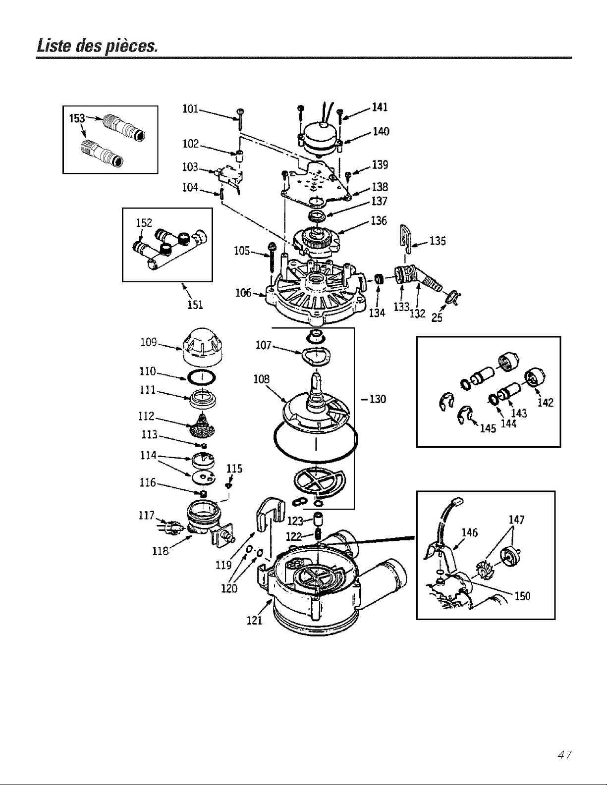
Listedespi6,ces.
152
141
138
\
151
1331:25
120
- 130
147
/
146
/
121
47
Page 48

Cataloguedespioces.
GENERAL ELECTRIC CATALOGUE DES PII_CES
NODE
R :FERENCE
0003
0004
0005
0007
0008
0009
0010
()011
0012
0013
0014
0015
0016
0017
0018
0019
0020
0021
0022
0023
0024
0025
0026
0027
0028
0029
0030
00B1
0032
0033
0034
0035
0036
0055
0056
0999
NO DEPII_CE
WSBSX10001
WSB4X10013
WSB4X10011
WSB4X10012
WS07X10004
WS14XI0002
WS14XI0001
WS01XI0002
WSB2X10001
WS32X1001l
WSB1XI0001
WS31X10002
WS21XI0006
WS21X10011
WS19XI0003
WS06XI0003
WS26XI0001
WSB1XI0010
WS33XI0001
WS33X10002
WS31XI0003
WS02XI0009
WS32X10002
WS02X10011
WS32XI0003
WS18X10003
WS22XI0016
WS22X10017
WS35XI0002
WSI5XI0005
WS35XI0003
WS{}3XI0006
WSISXI0006
WS03XI0007
WS03XI0008
WS07XI0002
WS07X10003
WS28X10003
WS28X10004
49-50061
DESCRIPTIONDESPIECES
TROUSSEDEJOINTSTORIO.UES l I l
DECAI.COMANIE I
DI_2CALCOMANIE I
D_2CALCOMANIE I
TUYA[ DEVIDAN(;E,20PI 1 1 1
COUVERCI£DUDISTRIBtTEtR I 1 I
FONDD[ DISTRIBtTE[R 1 1 1
R}2SINE-1I'I.CUBE I 1 I
Rf2SERVOIRDERESINE l
Rf2SERVOIRDER_2SINE I l
COUVER(IEDE'FOND l l l
COETER(£EI)UPANND_UI)EC(),_I,_L4NI)El l l
t'ANNE4_UDECOMXL_NDE l
t'ANNE_UDECOMXL_NDE l l
FAISCE_UDEFILS l l l
FILD'MIMENTATION l l l
TRANSFORXL_TEUR l l l
COUVERCLED'ORIFICEDE 1 1 1
REMPIISSAGED[ SEI
_2CK_ND'_2TANCH_2ITI:2,_IAVAPEURI 1 1
BORD 1 I 1
COUVERCIE DUCONTENANT 1 1 1
DESOLUTIONSAIINE
ECROt t'At}III_ON,1/4 PO.-20 I 1 I
(2__VIT}2DURf2SERVOIRDE I I I
SOLUTIONSALINE,ARRONDI
VIS,1/4PO.-90NYLON 1 1 1
RI"2SERVOIRDESOI,UTION 1 I I
SAI,INE,ARRONDI
ATTACHEDET1.'_24_1 1 1 I
ADAPTEURPOURTt'_2_[.' I 1 I
RON1)EII£ l 1 l
TROtSSE DEFI?"L__TIONAt SOL l 1 l
ENSEMBI£D[ ROBINET l 1 l
DESOI,UTIONSAIINE
ENSEMBI£D[ H,OTTEUR, I I I
TI(;EET(;tIDE
ATTACHE 1 1 1
CORPSI)UROBINETI)ESOLUTIONSALINE1 1 1
ATTACHE 1 1 1
(;RILI£ 1 1 1
ENSEMBI£DESCONDtlTES 1 1 1
CONDUITEDESOIITTIONSAIJNE 1 1 1
ATTACHEDEH?,,L_TION 2 2 2
COIIIER DESERRA(;E 2 2 2
XL_NI.ELDUPROPPdETMRE l I l
ETDIRECTIVESD'INSTAII ATION
48
Page 49

Cataloguedespieces.
GENERAL ELECTRIC CATALOGUE DES PII_CES
NODE
R]E_RENCE NO DEPII);CE DESCRIPTIONDESPI]ECES
0025 WS1SXI0003 ATTACHE DE TUYAI. l l l
0101 WS02X10012 VISNO4-24XI-I/SPO 1 1 1
0102 WS02X10013 ENTRETOISE 1 1 1
0103 WS21X10003 INTERRUt}TEUR 1 1 1
0104 WS03X10009 BROCHED'EXt'ANSION 1 1 1
0105 WS02X10014 VISNOI0-14X2PO 5 5 5
0106 WS31X10006 COI.VERCI£DEROBINET 1 1 1
0107 WS03X10010 RONDELI£ 1 1 1
0108 WS26X10002 ROTOR&DISOI'E 1 1 1
0109 WS19X10004 COI.VERCI£ 1 1 1
01D WS03X10011 JOINTTORIOUEI.1 POX1.4PO 1 1 1
0111 WS19X10005 SUPPORTDE(;RILI£ 1 1 1
0112 WS03K10013 GRIII£ 1 1 1
0113 WS22X10020 BOI.CHONR_2GUIATEI.RDE 1 1 1
0114 WS08X10005 JOINT, GI(I£UR/VENTURI 1 1 1
0115 WS03K10015 (;RIII£CONIQUE 1 1 1
0116 WS22XI0021 BOI.CHONDECONTROIE 1 1 1
0117 WS03X10017 EMBOUTD'f2CROU 1 1 1
0118 WS15X10009 ENSEMBI£DE6ICI.EI,R/ 1 1 1
0119 WS03X10018 BOI,I,ONDERETENUE 1 1 1
0120 WS03X10019 JOINTTORR)UE1/4POX3/8t}O 2 2 2
0121 WS15X10010 CORPSDEROBINET 1 1 1
0122 WS03X10020 RESSORT 1 1 1
0123 WS22X10022 BOUCHON,VIDAN(;EDI.SEI 1 1 1
0130 WS35X10005 TROUSSEDEJOINTS 1 1 1
0132 X_\S22Xl()023 ADAPTEI.RPOI.RTI.YAI. DE 1 1 1
0133 WS03X10021 JOINTTORIOUES/8 POX13/16 PO 1 1 1
0134 WS03X10022 BOUCHONREGI.IATEURDE 1 1 1
0135 WS03X10023 ATTACHE 1 1 1
0136 WS26X10003 CAME&ENGRENA6E 1 1 1
0137 WS26X10004 PAIIER 1 1 1
0138 WS26X10005 PIA().UEDUMOTEUR 1 1 1
0139 WS02X10015 VISNO 6-20 X3/8 PO 2 2 2
0140 WS26X10006 ENSEMBI£DUMOTEUR 1 1 1
0141 WS02X1001{; VISNO{;- 20X7/8 PO 2 2 2
0142 WS60X10001 f2CROI.[)'INSTAllATION 2 2 2
0143 WS60X10002 T[BED'INSTAIIATION 2 2 2
0144 WS60X10003 RONDELI.E 2 2 2
0145 WS60X10004 ATTACHE 2 2 2
0146 WS28X10005 LOGEMENTDUDI'_2TECTEUR 1 1 1
0147 WS19X10006 ENSEMBI£DEIATURBINE&SVt}PORT1 1 1
0150 WS03X10024 JOINTTOPdOI.E 1 1 1
0151 WS15X10012 ENSEMBIEDUROBINETDE 1 1 1
0152 WS03X10025 JOINTTORIQI,E 2 2 2
0153 _\S60X1()006 ADAPTEI.R 2 2 2
DEBIT,.1GI'M
DEREMPIISSA(;E,.3Gt'M
VENTt RI
VIDANGE
[)I_2t3IT,COMMANDEDERIN(_A(;E
DERIVATION
_NOTE:I_es(;odes de l'dtat du Massachusetts exigent que l'insmllafion soit efli_cmde par un plombier
qualifid et n'autorisent pas l'ufilisation de robinet f,bride. Pour l'installafion, ufilisez le {;ode de plombage
24&CMR du Commonweahh du Massachusetts.
49
Page 50

Notes
50
Page 51

Garantiedu sltst#me adoucisseurd'eau de GE(pourconsommateurs auCanada)
_ ous les services couverts par la garantie sent fournis par les Centres de Service de I'usine ou par un
technicien. Pour le service, appelez sans frais 1-866-777-7627.
Pour la periode de : /VoLtsremplacemns :
Unan
/_partir de la date
d'achatoriginal
Troisans
/_partir de la date
d'achatoriginal
Oixans
/_partir de la date
d'achatoriginal
Ce qui n'est pas couvert :
• I,es d(_placements de service a domicile pour vous
enseigner (omment utiliser le produit.
• Installation in(orre(te.
Si vous avez un probl0me d'installation, contactez votre
vendeur ou votre installateur. Vous (_tesresponsable
pour fimrnir une installation (_lectrique ad(_quate,
l'(Schappement et d'autres possibilit(Ss de branchement.
Toutcomposantdusyslt_meadoudsseur d'em] qui cesserade fimcfionner ;'_la suite d'un (letimt
matdriel ou de fhbrication. At] corns de cette garantiecomplOtede uneannee,GEassurerasansfrais
les travaux et secvice a domMle pc)ur le remplacement des pi(Sces(l_Iecmeuses.
t_cran electronique s'il mmbe en panne a la suite d'un d4iimt mat4riel ou de t,tbrication. At] cours
de cette garantie limitee de trois ans,vous serez responsable de t{)us fiais de main-d' oeuwe ou
de sevvice a domicile.
Pourleremplacementdureservo#desolutionsalineoudureservo#deresinesil'un ou l'aune
prdsente un ddfaut matdriel ou de thbri(ation. Au (ours de (erie garantie limitee de dix
annees, vous serez responsable de tous flais de main-d'oeuwe ou de service a donficile.
• Le remplacement des fl]sibles de la r4sidence ou le
r4en(lenchement des disjon(teurs.
• I,e non-tbnctionnement du produit si cehfi-ci n'a pas (_t(_
correctement utilis(_ ou s'il a (_t(_utilis(_ dans un but autre
que cehfi pour lequel il a (_t(_cono], ou encore s'il a (_t(_
utilis(_ commercialement.
• I,es dommages caus4s par accident au produfl, les
in( endies, inondations ou a(tes de Diet].
........... _ _RESPONSABI E DES DOMMAGES INDIRECTS
L OR(,ANISME (,ARANT NEST IAS ..... ]
[ Organisme garant : (_AMCO INC. ]
51
Page 52

Num6msdeteldphonepourleservice.
GEAnswerCente_ auxEtets-Unis:800-626-2000
I,e (;E Answer (enter <'_estouvert 24 heures sur 24touslesjours de la semaine.
AuCanada,uontactez le Directeur des Relauons avec le ( onsommateur, 1Facto U I,ane,
Suite 310, Mon(ton, N,B, E1C 9M3
OIl
Visitez notre site Web a www.geappliances.com
Serviceder4parations_ domicileAuxE-tats-Unis:800-432-2737
I,'expert du servk e de r_paration de (;E peut _:tre rejoint par un simple appel t_l_phonique.
Au Canada, appelez sans flais 1-866-777-7627.
Servicedesbesoinssp4ciauxAuxE-tats-Unis:800-626-2000
GE oflie sans fiais un ddpliant pour Lwiliter la disposition d'une cuisine sans barri_re p_tur personnes
amobilit_ r_&fite. AuxEtats-Unis,appelezle 800-TDD-GEAC(800-833-4322).
AuCanada,contactez le Directeur des Relations avec le ()mSOlnlnateui, 1Facto U I,ane,
Suite 310, Moncton, N,B, E1C 9M3,
ContratsdeserviceAux /_tats-Unis: 800-626-2224
Faires l'achat d'un conu at de selx'ice (;E aloi s que voti e gat anUe est tou'oui s ell vigueui et vous
bdndficierez d'une rdduction substantielle. I,e ser_dceaux consommateurs de (;E sera toujours
prdsent lorsque votre garantie sera expirde.
Au Canada, appelez le 1-800-461-3636.
Pieces et accessoires Aux I_tats-Unis: 800-626-2002
I,es personnes qualifiOes pour assurer l'enueden de leurs appareils mOnagers peuvent obtenir
des pi_?(es ou a_cessoires qui seront exp_di_s dire( tement fileur domkile (les (aries VISA,
Master Card et Discover sont acceptdes).
Lesinstructions contenues dans ce manuel couvrent les procedures a effectuer par tout usager.Les
autres types de service deivent engeneral _tre referes a dupersonnel de service qualifie. Prendre
teutesprecautions car une intervention de service incerrecte peut rendre I_tilisatien hasardeuse.
Au Canada, consultez les pages jaunes pour obtenir le no local de Camco.
52
Satisfactiondu service
Sivous _:tes insatisfait du service recu de (;E :
Initialement,contactez les personnes qui ont assui_?le service de voue appardl.
Ensuite, aux Etats-Unis, sivous _:testoujours insadsi_tit, envoyez t{tus les ddt;fils incluant votre no
de tdldphone a : Manager, Customer Relations, GE Appliances, Appliance Prok, I,ouisville, KY
40225. Ou, au Canada: Directeur, Relations avec le ( onsommateur, (amco Inc., 1 Facto U I,ane,
Suite 310, Moncton, N.B., E1C 9M3.
Imprim6 aux Etats-Unis
Page 53

Laseccion Espa oL
b_strucciones de Seguridad
Instalad6n apropiada ........... 55
Instrucciones de instalaci6n
Conexiones de desagOe ...... 59, 60
Desempaquetado e inspecd6n ...56
Desinfecci6n ................... 62
Especificaciones y dimensiones...(32
Herramientas y materiales
requeridos .................... 57
Instrucciones de instalaci6n . .56-58
Instrucciones paso por paso . .59-62
Planificaci6n y localizaci6n ...... 57
Programaci6n del control ....... 61
Recomendaciones importantes . .56
Consejos sobre las instrucciones
de oTheraci6n
Caracteristicas .............. (35, (3(3
C6mo limpiar la ensambladura
de la boquilla y el Venturi ....... 64
C6mo regenerar el sistema ...... 68
Diagn6sticos electr6nicos ........ 67
Rotura de un puente de sal ...... 64
Se,s'icio ....................... 63
Sistema de descalcificaci6n
de agua .................... 63-68
Visualizaciones de los controles . .65
Cuidado y limpieza
I,impieza del hierro del agua ..... 68
Nivel de almacenamiento y
rellenado de sal ................ 68
Consejos para la identificaci6n
y soluci6n de av_as ...... (39-71
Selwicios al consumidor
Garantia ..................... 76
Lista de partes/cat_logo ..... 72-75
Nflmeros telef_3nicos
importantes ......................... 79
53
Page 54
GE& Usted,UnaAsociaci6n deSetvicio.
ilMPORTANTE!
IJene 1;iT_njeta de Regisuo del l'roducto del Consumidor.
iDes formas faciles de registrar su electrodomestico!
• A Um-ds de l_llnternet en m_v.geappli_mces.com
• Complete y envfe per coneo la Taljeta de Registro del Pro&acre
PARASUSRECORDS
Escriha /os n#meros de mode/o y serie aquL"
#
#
I'uede en(onunrlos en el sopone de] sumidero.
Guarde los recibos de venta o los cheques cancelados aqut
I_J pmeba de l;i ie(hn de (omprn originnl es ne(esnrin pnvn obtenev serd( io b_ljo l;Jg;irnmia.
(_ LEAESTEMANUAL
En el interior en(omrar_ mu(has ideas fltiles de c6mo usar y mantener su sistema de agua apropiadamente. Un
po(o de (uidado preventive de su pane le puede ahonar mu(ho tiempo y (finero durante la vida de su sistema.
SINECESITASERVICIO
U sted en(onuar_ muchas respuestas a problemas comunes en la se(ci6n Antes de Llamar para Soficitar Servicio.
Si inspecciona pfimero nues[i_l tabla de Consejos para la Identificaci6n y Soluci6n de Averias, quizas no [ellg_l que
llamar para solicitar sendcio.
Si en etecto usted necesita secdcio, rel_jese y tenga la segufidad de que la a)a_cla necesafia la enconuar_ con soh)
llamarnos per teKfi)no.
Heroes inchfido una lista de nfimeros de secdcio gramitos para el cliente en la cubiena posterior.
Visite nuestra p_na en la Internet: www.geappliances.com
54
Page 55
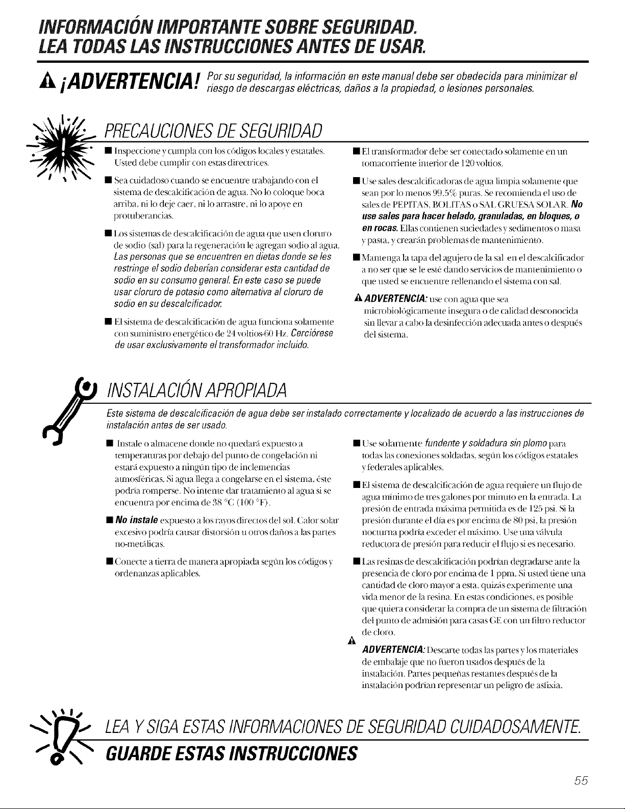
f
INFORMACIONIMPORTANTESOBRESEGURIDAB.
LEATODASLASINSTRUCCIONESANTESBEUSAR.
riesgo de descargas el_ctricas, dafios a la propiedad, o lesiones personales.
PRECAUCIONESDESEGURIDAD
• h-lspecdone y cuml)la con los c6digos locales yestatales.
Usted debe _xmlplir con estas directrices.
• Sea €uidadoso cuando se encuentre trabajando con el
sistema de descalcificaci6n de agx]a. No 1ocoloque boca
arriba, ni lo deie caer, ni lo arrastre, ni lo apoye en
protuberancias.
• 1x)s sistemas de descalcificaci6n de agua que lBen domro
de sodio (sal) para la regeneraci6n le agTegan sodio al ag'ua.
tas personas que se encuentren en dietas donde se les
restringe el sodio deberfan considerar esta cantidad de
sodio en su consume general. En este caso se puede
usar cloruro de potasio como alternativa al cloruro de
sodio en su descalcificador.
• El sistema de descalciti_ aci6n de agua fundona solanmnte
con suministm energ-atico de 24 vohios-60 Hz. Cergi&ese
de usar exclusivamente el transformador incluido.
• El translibrl-nador debe set conectado solal-nente ell llll
tomacorriente interior de 120 voltios.
• Use sales descalcificadoras de ag'ua limpia solamente que
sean por 1omenos 99,5% puras. Se recomienda el uso de
sales de PEF'ITAS, B( )LITAS o SAL (_RU ESA SOLAR./'fie
use sales para hacer helado, granuladas, enblowes, o
en rocas. Ellas contienen suciedades y sedimentos o masa
y pasta, y crearfin problenlas de nlantenimiento.
• Mantenga la tapa del agl_iero de la sal en el descalciticador
a no set que se le estd dando servicios de mantenimiento o
que listed se encuentre rellenando el sisterna con sal.
A ADVERTENCIA: use con aglla que sea
rnicrobiol6gicanmnte insegura o de calidad desconocida
sin llevar a cabo la desintecci6n adecuada antes o despuas
del sistema.
INSTALACIONAPROPIADA
Estesistemade descalcificaci6n de aguadebeser instaladocorrectamentey localizadodeacuerdo alas instrucciones de
instalaci6nantesde serusado.
• lnstale o ahnacene donde no quedarfi expuesto a
temperaturas por debajo del punto de congelaci6n ni
estarfi expuesto a ningfin tipo de indemencias
amlosff, ricas. Si ag'ua llega a congelarse en el sistema, d'ste
podria romperse. No interne dar tratamiento al agua si se
encuentra por encima de 38 °C (100 °F').
• 17o instale expuesto a los rayos directos del sol. Calor solar
excesivo podria causar distorsidn u otros dafios alas partes
no-l-netfilicas.
• Conecte a tierra de rnanera apropiada segOn los c6digos y
ordenanzas aplicables,
• Use solamen/e fundente y soldadura sin plomo para
todas las conexiones soMadas, segtln los cddigos estatales
ytederales aplicables.
• E1sistema de descalciticaci6n de ag_la requiere tm fluio de
agna nlillil-no de tres galones pot nlilllltO ell la entrada, l_a
presi6n de entrada maxima permitida es de 125 psi. N la
presi6n durante el dia es pot encima de 80 psi, la presidn
nocmrna podria exceder el rnfixirno, Use tma vfilvula
reductora de presi6n para reducir el flujo sies necesario,
• I as resinas de descalciticaci6n podrian degradarse ante la
presencia de cloro por encima de 1 ppm. Si usted tiene tma
cantidad de cloro mayor a esta, quizfis experimente una
vida menor de la resina. En estas condiciones, es posible
que quiera considerar la compra de tin sistema de fihraci6n
del punto de admisi6n para casas GE con tm fihro reductor
de doro.
A
ADVERTENCIA:Descarte todas laspanes y los materiales
de embala.jeque no _ueron usados despuas de la
instalaci6n. Partes pequefias restantes despuas de la
instalaci6n podrlan representar tm peligro de ast£-da.
LEAYSIGAESTASINFORMACIONESDESEGURIDADCUIDADOSAMENTE.
GUARDEESTASINSTRUCCIONES
55
Page 56

Instruccionesde instalacion.
_PRECAUCION: Se necesita ciena habilidad de plomeria para la instalaci6n. Si usted no est_ seguro acerca
de la instalad6n de alguna de las panes de este produ(to, (onsuhe a un plomero profesional.
Desempacado e inspeccion
Cerci6rese de inspeccionar completamente el descalcificador en busca de dafios durante el env_o o panes que
puedan haberse perdido. Tmnbi_n note dafios al (art6n de env_o. P6ngase en contacto (on la compafi_a de
Uanspone para (ualquier redamo per dafio o pdrdida. E1 fhbfi(ante no es responsable per dafios sufiidos
durante el u_nsito.
I_as partes pequefias necesafias para instalar el descaldfk ador se encuentran en una pieza de (an6n
tem_oconfom_ada. Para evitm la p6rdida de las panes pequefias, mantengalas en el paquete
tem_o( onfom_ado hasta que usted est6 listo para usmlas.
Recomendaciones importantes para la instalacion
I_eael manual complete. No guiarse per las (firecuices y reglas po(h_a causm lesiones personales o dafios a la
propiedad.
• Antes de comenzar la insmlad6n, lea estas Instmcdones de instalad6n complemmente. I amgo, obtenga
todos los matefiales y henamientas que necesitm_ pma llevm a cab() la ins/alad6n. No ins/aim
conecmmente el descalcificador invalida la gmamia.
• Revise los c6digos locales. I,a instalaci6n debe cumplir tales requisites.
• En el estado de Massachusetts, la instalaci6n debe ajustarse al C6digo de Plomeria 248 CMR. Consulte a su
plomero certificado.
° Use solamenm fimdenm y solda(hna sin plomo pma todas las conexiones dulces soldadas, segOn los c6digos
estatales y tederales aplicables.
• Conecte el descaldficador en la/uberia (D suminisuo pfindpal antes del calenmdor de agua. NO HAOR
PASAR AGUA CALIENTEA TrAVES OELDESCALCIFICADOR.I_t temperamra del agua que pase a uaves del
descaldficador debe set menor de 49 °( (120 °F).
• Tenga cuidado cuando maneje el descaldficador. No lo coloque boca aniba, ni lo deje caer, ni lo anasue, ni
lo apoye en promberancias.
• I_xpresi6n de enuada maxima penniti(h es de 125 psi. Si la presi6n dman/e el (lia es pot endma de 80 psi, la
presi6n nocmrna po(hia exceder el maximo. Use una wilxafla reductora de presi6n pma redudr el flujo si es
necesmio. (Agregm una valxafla re(hloora de presi6n po(h_a re(h_dr el flujo.)
• E1sistema de descaldficaci6n fimdona solmnente con 24 volfios-6/! Hz. ( erci6rese de usar ex( lusivamente el
uansfi )nnador incluido. ( erci6rese de que el tomaconiente el(_ctfico y el transfi)mmdor estan en el interior
de un recinto pma protegerlos de la humedad.
• Consuhe la secci6n 06ndo instalar el doscalcificador pma m_s delalles.
56
_ADVERTEIVCIA: No use (on agua que sea mi(rol)iol6gi(amente insegura o de (alidad desconocida
sin llevar a cabo la desintecd6n adecua(h antes o despuOs del sistema. E1 agua debe set proba(h
pefi6dicamente pma vefificar que el sistema seem uenua fimdonando safisfimtofiamente.
Panes pequefias restantes despu_s de la instalaci6n po&_an represemm un peligro de astixia.
Page 57

Planifique come instalargl el descalcificador
I_oprimero que debe de( idir es (dine insmlar las mberias entrando y saliendo del des( aMfi(ador. F!jese en
la all)erie de ague en el Dmto donde usted conectar5 el descalcificador. _Est5 la tuber_a soldada con cobre,
pegada (on plastic:o, o ros( ada galvanizada? _Cual es el tamaflo de la tuber_a?
_ABVERTENC/A: Use solamente flmdente y soldadura sin plomo para todas las conexiones soldadas,
prevenir envenenamiento de plomo.
Consuhe la Ilustracidn de instalacidn tipica,Fig. I. 0sela come una guia pare planificar su instalacidn protitular.
CerciOresededirigirelsuministro deagueduraentranteal aceplamientede admisiOnde la v_/vu/ade/
descaloificador.Lav_il'm]aest;imar(ada IN (ENTRAOA)yOUT(SAUOA).Vea la ilusuad6n en lap_igina 58 para
ayudarle a prepararse:
Oondeinstalar el descalcificador
=Coloque el descaMficador lo re;is cercano posib]e a un sumidero, o a otto puree de (henaje o cohmma
de suministro.
=Se recomienda que los gri%s externos se dejen con agua &ira para asi ahorrm agua descaMficada y sal.
=No instale el descalcificador en un hlgar deride se Dmda (onge]ar. Los da_es debide al cengelamiente no est_n
cubiertosper lagarantia.
*No insmle el descal( ificador donde pueda b]oquear el acceso al (alenmdor de agua o el acceso a la vaMfia de
(ierre prin(ipal del agua.
*Coloque el des( al(ifi(ador en un lugar donde sea menos probable que ocurra daflo causado per el agua si
es que evenmalmente ocurriese alguna fllga. E1tilbricame no reparara ni pagara per daflos ocasionados
per ague.
*Un tomacorrieme de 120 volOos es necesario pare (onecmr el nansfinmador que viene inchfido. El
descalcificador fiene un cable eldctrico de 10 pies. Si el tomacorriente esta colocado demasiado lejos (haste
1O0pies), use un (;able calibre 18 pma conectmlo. CerciOresedequeel tomaoorrienteel_ctricoy el
transformadorest_nen el interiordeunreointoparaprotegerlos de lahumedad.Cer(i6rese de que el
tomacorriente estd desconectado pare prevenir un corte el4cnico accidental.
oSi se dispone a llevar a cabo la instalacidn en el exterior, usted debe dar los pesos necesarios para asegurarse
de que el descal( ificador, ]a insmlacidn de plomeria, el (ableado, etc. estan mmbidn prote_dos de los
elementos (rayos del sol, lluvia, viento, calor, file), de la comaminacidn, vandalismo, etc. tel y come lo
estar_an si tueran insmlados in[ernamente.
• Mantenga el desoalcificador alejado de los rages direotes de/sot E1calor del sol podr_a causer distorsidn u
otros defies a las panes no-met;ill( as y podr*a hacer daflo a las pazles electrdnicas.
Herramientas ymateria/es neeesariospare la instalacion
*I_os ajustes de entrada ysalida in(brides (on el descal(ificador son robes de (obre de 1,91 (m (3/4")-
nominal. Pma mantener llena la v_ilvula de flujo, se recomienda el use de robes de 2,54 cm (1") a parfir de los
ajust es del descaMficador. Come robe alimentador de agua, usted debe mantener el un tamafio igual o
mayor, hacia la enuada y salida del descalcificador.
o Use la wih'ula de bypass inchfida pare insmlm el descaMficador. Ia %lvula de bypass le permite desconectar
el suminisuo de agua hacia el descalcificador pma proporcionmle servicio, pete afln manfiene el agua
llegando alas mber_as de la casa. I_os ajustes de entrada y salida a que nos retbrimos anteriormente se
conectan a la %lvula de bypass con las mercas y arandelas inchfidas.
o Use ajustes y mbeffas de cobre, lat6n o galvanizados. Algunos cddigos po&*an permifir el use de tuber_as
plasticas CIWC.
oSi una manguera adicional es necesmia para el drenaje de lavalvula y el mnque de sal, usted la puede solicitor
Ham_indonos al Cemro de Respuestas de GE (GE Answer Cemer: ) a] 800-626-2000.
oSi necesim una wilvula r_gida de drenaje pma ('umplir con los c6digos de plomer_a, po&*a comprar las palles
necesarias para conectm un drenaje de mberia de cobre o p]asfico de 1,27 cm (1/2").
oSal del descalcificador en una pepim limpia o bolim de agua es necesaria para Henar el mnque de agua
salrm_era, consuhe las Instruccionesde Instalacidn PasoporPasoen el Paso8.
57
Page 58
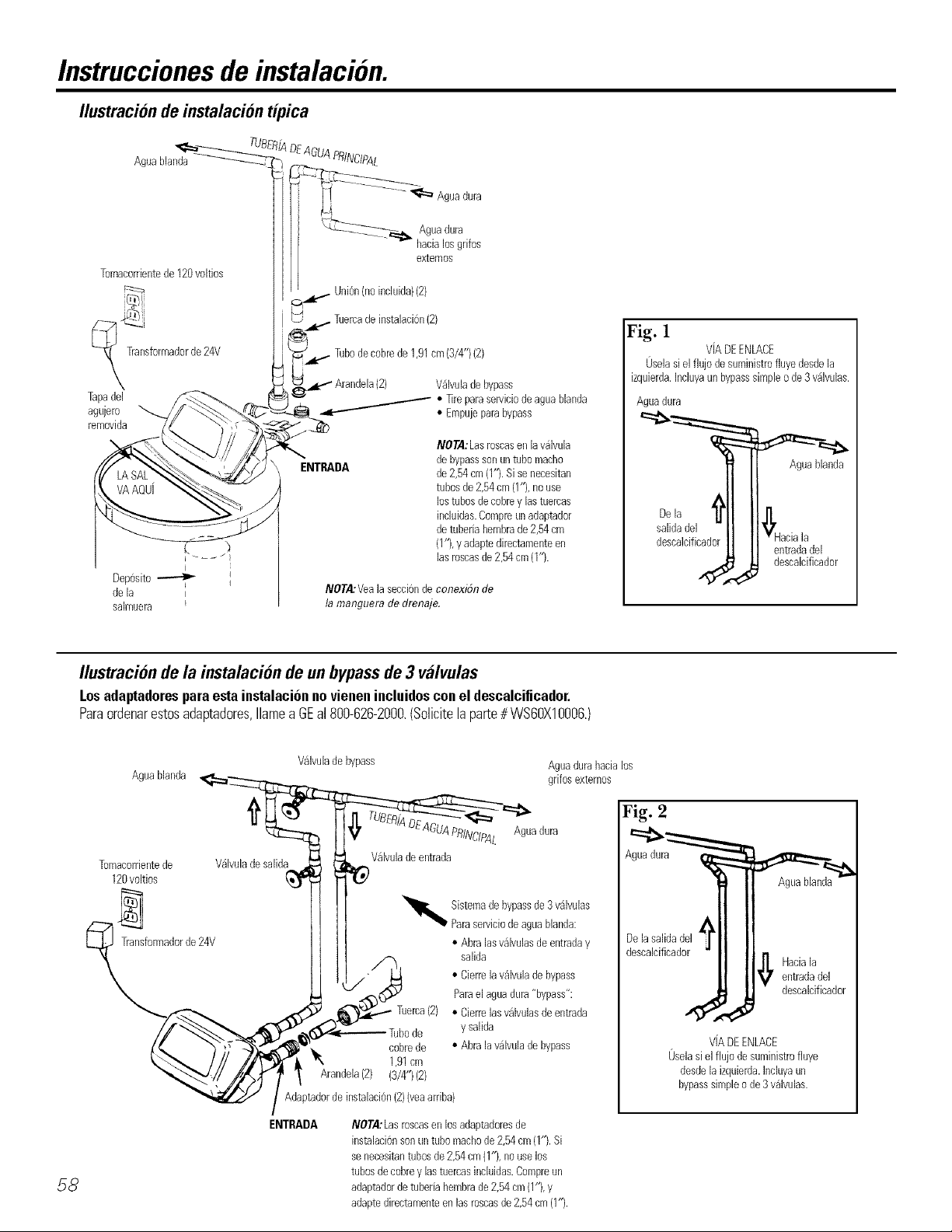
Instruccionesde instalacion.
Ilustracion de instalacion #pica
Aguablanda
Tomacorrientede120voltios
Transformadorde 24V
Tapadel
agujero
removida
Deposito_
dela i
salmuera
j I
DEAGUAPRINCIPAL
Aguadura
Aguadura
hacialosgrifos
exteroos
Uni6n(noincluida)(2)
Tuercadeinstalaci6n(2)
Tubodecobrede1,91cm(9/4")(2)
V_lvulade bypass
_,, ]]re paraserviciodeaguablanda
ENTRADA debypasssonuntubo macho
NOTA:Veala secci6nde conexiSnde
la manguera de drenaje.
• Empujeparabypass
NOTA:Lasroscasenlavalvula
de2,54cm(1").Sisenecesitan
tubosde2,54cm(1%nouse
lostubosdecobreylastuercas
inciuidas.Compretinadaptador
detuberiahembrade2,54cm
(1"},y adaptedirectamenteen
lasroscasde2,54cm(1%
Fig. 1
VIADEENLACE
0seiasiei fiujodesuministrofiuyedesdeia
izquierda.Inciuyaun bypasssimpleode 3 v_ivulas.
Aguadura
Aguablanda
Deia
salidadel
descalcificador
entradadel
descalcificador
Ilustracion de la instalacionde un bypassde 3 valvulas
Losadaptadoresparaestainstalaci6nnovienenincluidosconel descalcificador.
Paraordenarestosadaptadores,Ilamea GEal 800-626-2000.(Solicitelaparte# WS6OX10006.)
Valvulade bypass Aguadurahacialos
DEAGuAPRINCIPAL Aguadura
Valvulade entrada
"_iiiiii Sistemadebypassde3valvulas
cobrede
1,91cm
Arandela(2) (3/4")(2)
Adaptadordeinstalacion(2)(veaarriba)
ENTRADA
NOTA:Lasroscasenlosadaptadoresde
instalaci0nsonuntubomachode2,54cm(1%Si
senecesitantubosde2,54cm(1"),nouselos
tubosdecobreylastuercasincluidas.Compreun
adaptadordetuberiahembrade2,54cm(1%y
adaptedirectamenteen lasroscasde2,54cm(1%
Paraserviciodeaguablanda:
• Abralasvalvulasdeentraday
salida
• Cierrela valvuladebypass
Paraelaguadura"bypass":
• Cierrelas valvulasdeentrada
de
y salida
• Abralavalvuladebypass
58
Aguablanda grifosexternos
Tomacorrientede
120voitios
Transformadorde24V
V_lvulade salida
Fig. 2
Agua dura
A
Delasaiidadel
descalcificador
,J
ViADEENLACE
0selasielfiujo desuministrofluye
desdeiaizquierda,inciuyaun
bypasssimpleo de9 vaivulas.
Aguablanda
_! r Hacialaentradadei
descalcificador
Page 59

Instruccionesde instalacionpasopor paso.
• Suspertda el suminisu'o de gas o de energ'ia el(?cu'ica que alimenta el cMentador de agua,
en la posibilidad de que el (alentador p{ieda drenarse mientras usted drena las tube}'ias.
• l)esconecte el suministro de aglla hacia los tubos que han de ser cortados y drone las
tuberias de agua de la casa.
• Abra los gritos de agxla caliente y los de agxlaIlia.
1.1NSTALE LA VALVULA DE BYPASS
__I Salida
• Remueva el tap6n plfistico de embalaje y el alambre de la salida de la v;ilvula.
,, ;22sbg2Sso, ,a
NOTA: (;el ci6rese de que la mrbina
y el soporte se encuentrcn Ill-rues cn
sus posiciones en la salida de la
vfilxatla. Sople hacia la boquilla de la
v_il_tla y ol)set_m que la turbina se
encuentra rot_/ndo libremente.
Salidade la valvula
Ejedeturbina
y soporte
• Empuje la v_ilvula (to b_pass (lubrique los aros t6ricos c()n g-rasa (to silicona) hacia ambas
1)oqu_llas de la vfilvula }:inno se muestra en la Fig. 3A. '
• Enganche los dos clips pl_isticos ell sus p(lsiciones, a partir del la parle superior vhacia Fig. 3g
al)_jo, (;omo se muestra el1las Figs. 3A y 3B. Cerci6rese de engancharlos en sus lu,gares
apropiados. Tire de la _r,ilvula de bypass para cerciorarse de que se encuen_ra sostenida VISTA
con seglwidad en su lugar. LATERAL
2.MUEVA IA ENSAMBLADURA DEL DESCALCIFICADOR HACJA SU
POSICION DE INSTALACION:
• Cerci6rese (teque la superti_ie tie instala(idn se encuenu'a nivela(ta v lisa. Cual(luier objeto
cortante debajo del tanque podria causar una hendidura ell el misn{o. Si es necesario. "
coloque el tati(lue sobre una secci6n (te pl)_vood tie urt grueso rn_iximo tie 1,91 crn (3)4").
(lesi_dciticador.IAlepo, coloque Ctll'/asdeba'o.] (tel pl'_-,vood,segOn sea necesario Data nivelar el
3. APLOME HACIA DENTRO Y HACIA AFUERA LAS TUBERiAS HACIA YDESDE EL
DESCA_LCIFICADOR:
PRECAUCION: Si a to(las las -/recauciones simfiemes miemras cone('ta la -/lomeria lie
enu'a(la y sallda. Vea las Ftgs. 1) 2,
• _ ._ _; ..... _ ........ 1;
A • (;F21_.(;IOI_.F2SEI)F2(!LIE F2LSUMINISTP.() I)E AGUA DURA I)E ENTILkI)A EST,:& Fig. 3C
I)IP.E(;TAMENTE (;()NECTAI)() A l _'_B( )QU ILl_'_ I)E ENTRADA I)EL
I)ESCAI _(;IFI(;AI)()P.. Si el tlu odel agua (te la casa viene (tes(le la iz{tuier(ta, use una
via de enlace de plomerla (omo se lnuestra ell la Fig. 1.
• Sise dispone a llevar a cabo una instalaci6n con soldadura de cobre, haga mdas las
soldaduras antes de coneetar los tubos a la vfilvula de bypass. El calor (to antorcha daft arfi
las partes pl_sticas.
• (_uan(to se encuertu'e giran(lo aBlstes lie tul)eiia roscados hacia @isles plfisticos, cerddrese
de no cruzar las roscas.
• Use un compuesto de junta de tul)erias en todas las roscas externas.
• _pove;, ....la tu )ella de entrada.,v lie salida de al_,una manera,(use, c( lgadores, de tuberia) para Fig. 4
evltar que el peso sea depos_tado sobre los ajustes de las vfilvulas.
4. CONECTE Y HAGA FUNCIONAR LA VALVULA DE LA MANGUERA DE
DRENAJE:
• Use la vfilvula de la mang_lera (te (lrenaje (so ha in¢lui(to una (te 20 pies) para adherirla al
@lste (te la wilvula de (h:enaje del ajust& Para evitar que la presidn del aglm expulse la
nlal-tgtlera, llSe [ll-la abraza(tera de nlal-l_tleras para aseg-urarla ell Stl lugar.
• O
Ixlcalice el otro extremo (le la rnang_lera en [lll punto apropiado para drenar (drenaje (le /
piso, sumidero, tina de lavanderla, etc.) que termine en el sistem_ide alcantarillado."
Cereidrese de cumplir con los eddigos locales.
IMPORTANTE: Si necesita m_ismanouera lie drena e, orddnela llamando al
• , )• , , _ • o.t - { t " * • *
I)epartarnento de I artes (to (,F_a18004)20-2002. E1desealofieador de ag'ua no ftmoona s_
esta agua no eseapa por esta manguera durante las regeneradones.
• Ate o amarre la manguera ell tin lugar cercano _-llpunto (to (lrenaje. Una aha presi6n de
ag'ua podria causar (iue el extremo _le la manoueril se rnueva errdticamente (ltwante los
ctclos de lavado reg-restvo v enlua_o-t}er_1pKtolie la generaodn. Tanbl&n deje tma toleranOa
de aire de al menos 3,80 em (i-1/}' ) enlre el exlremo de la mang'uera y el ptmto de
drenaje. Este espacio previene que ocurra un etecto sit_Sndel aglm (to alcantarillado hacia
el (tescalciticador, si ocurriese un ciclo (to lavado regresivo.
• O
Sitilera necesario levantar la rnang-uera basra un nivel superior al descalcilicador para
llegar hasta el punto (to (lren_!je, r_0 la eleve por eneima de 8 pies del piso. Elevar la
manguera demasiado podria causar una presi6n negativa que podria reducir la toma del
conteni(lo de sal (turante las regeneraciones.
Elsellodelarotorico valvuladebypasssonun
vaen[a muesca
externasolamente.El
clipengrapaen la muesca
interna(yeam_sadolante}.
Cuerpode la
valvuladeentrada
osalida
i SALIDA
VNvulade ! Espaciode ,
lamanguera 1 I'ZTom(I/Zr')_]
dedrenaje
DRENAJEDEPISO
tubomachode2,54cm(1'3.
Sisonecesitantubosde2,54
cm(1"),nouselostubosde
cobrey las tuercas incluidas.
Compre tin adaptador de
tuberiahembrade2,54cm
(1%yadaptedirectamente
enlasroscasde2,54cm(1").
Clip
X ISTADEL
Vfilvuladebypass
(empfijela al maximo)
ENTRADA
FRONTAL
Girelav_lvuladebypass
bocaarribaparaconectar
ala tuberiaalniveldelpiso.
toDtancia de
Abrazadera
COMUNADEAUMENTACION
Espaciodetoleranciade 5_
1,27cm(1/2")
Espaciode _"
toleranciade
Page 60
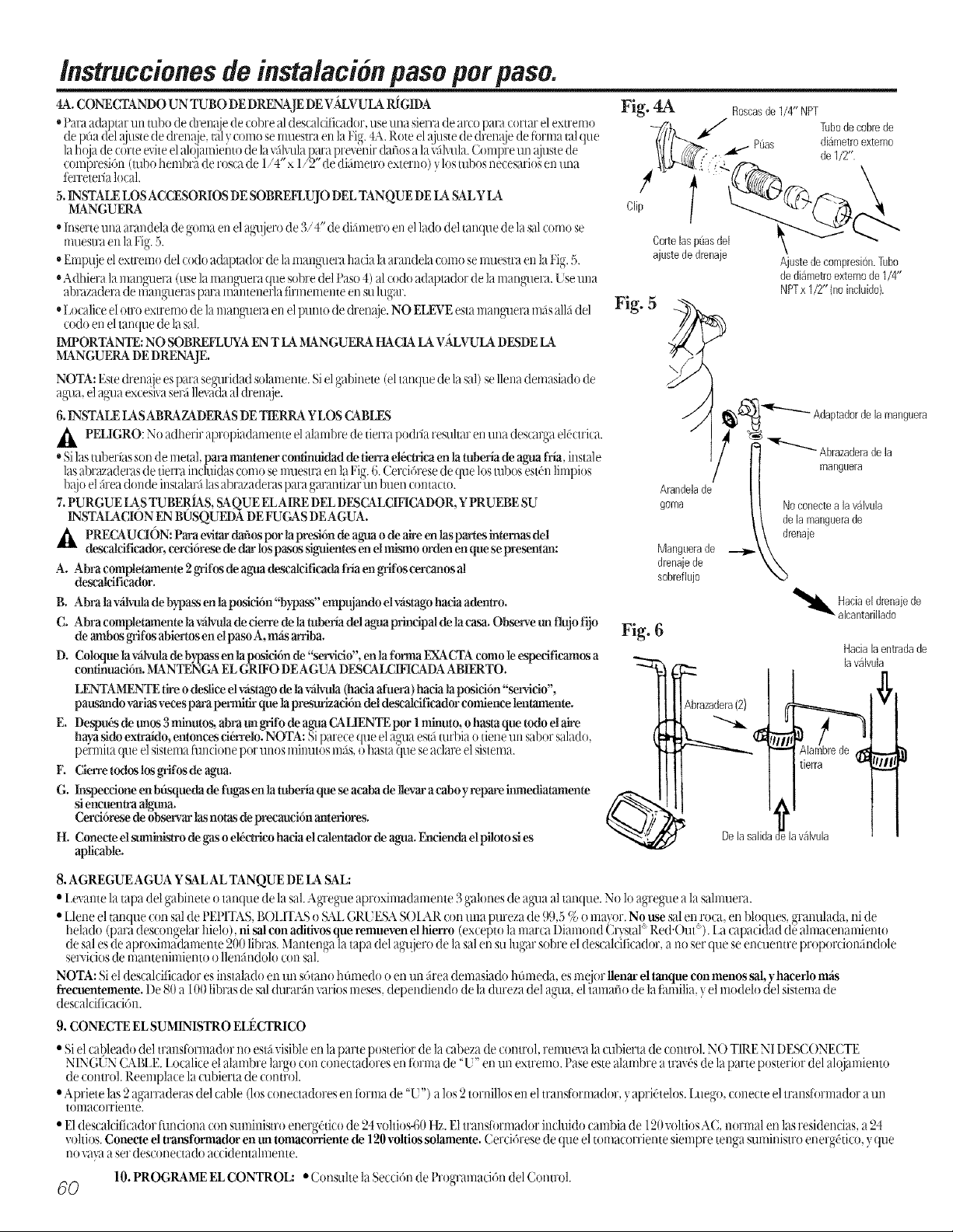
lnstruccionesdeinstalacionpasoporpaso.
4A.CONECTANDO UN TUBO DE DRENAJE DE VALVULARI[GIDA
*Para a(lklp[a[" lln tuba de (h'enaje detobre al des_alcil]cador, use lli]_l sierra (le al'(O para (oi't;u" el ex[Fell]O
de pfia delajuste de (lren;_e, [;il,,coma semuestra en la Fig.4A.Rote el ajustede drenaje de farina tal que
la ha a de cdrte eviteel alqjamieiatode la?_ilvula)_}u'apre',enir dafios a la:_-filxula.Clm@'e Iliaajuste de
(omi)resi6n (m ?ohem ?riide ['osGlde 1,4 x , 2 de difimetro externo) ,. as m ?as necesario_en alna
ferreteFa local.
5.INSTALE LOS ACCESORIOS DESOBREFLUJO DEL TANQUE DELA SALY LA
MANGUERA
'_lnserte una arandela de goma en elag_4jerode 3/4" de difimetro en ellado deltanque de la ,_dcoma se
muestra en laNg. 5.
,}Emp_{jeel extremo del coda adaptador de la mangalera hada la arandela coma senmesu'a en laFig.5.
"Adhiera la mangamra (use la mangl.mra(ue sabre delPaso 4) alcoda adaptador de la manglaera. Use una
abrazadera de lllangllel'aS pala ialantenerla firllleialente eli stl ltlgar.
'_Localiceel afro extremo dela mangamm en elpunto de dren_!ie.NO ELEVE esta mang_.mramilsallfidel
coda en eltanque de la s01.
DAPORTANTE:NO SOBREFLUYA EN T LA MANGUERA HACIALA VALVULA DESDELA
MANGUERA DE DRENAJE.
NOTA' Fste drena e espara segalridadsolamente Siel mbinete (eltanque de la sal/se llena demasiado de
agala,el againexces]xa serfillevadaaldrem!le.
6.INSTALE [ASABRAZADERAS DE TIERRA Y LOS CABI£S
_ PELIGRO: No adherir apmpiadamente el alambre de tierra podria resuhar en una descaNa eldctrica.
'_Silasmberias son de metal, pm-amanlener confinttidad de fien'a elficMcaen tamberia deagua fria, instale
lasabl'azaderas de tierra incluidas coit]ose lnuestra en lal.ig.6. Cerddrese de (lie los tllbosestdn limpios
1)@}elfirea (lon(le instalarfi las abr_wadel'aspara garantizar iln buen (ontacto.
7.PURGUE IAS TUBERIAS, SAQUE ELAIRE DEL DESCALCIFICADOR, YPRUEBE SU
INSTA[A(]ION EN BUSQUEDA DE FUGAS DE AGUA.
,_t PRECAUCI6N: Para evitar dafiospar la presidn de agua ode aire en las partes internas del
desealeificador, eereidrese de din'los pasos sigtfientesenel mismo arden en que se presentan:
A. Abra eompletamente 2grifus deagua desealcificada friaen grifuscereanusal
descak'ifieador.
B. Abra la vfilvulade bypass en laposici6n "bypass" empujmldo elv_istagohacia adentxo.
C. Abra completamente la vfilvulade cierre de la mberia del aguaprincipal de la casa. Observe un flujo fijo
deambos grifusabiertus en el pasoA, m_ arriba.
D. Coloque la v.,ilvulade bypassen la posieidn de"servicio', enla farina EXACTAcoma leespecificamos a
confinuaeidn.MANTENGA ELGRIFO DEAGUA DESCALCIFICADAABIERTO.
LENTAI_NTE tireo deslice elvfistago de la vfilvula(haciaafuera) hacia la posici6n "servieio',
pausando variasvecespara permitk- que lapresm'haci6n del descalcificador comienee lenmmente.
E. Despudsdeunos3minutos, abram_grlfodeaguaCALIENTEpor lnfinum, ohastaquetodoelaire
hayasido extraido, entonces ci6_Telo.NOTA: Siparece que elagalaestfiturbia o tiene un sabor salado,
perrnita que el sistema tilllCiol]epar ilnos lllinutos mils,o basra }lalese aclare el sistelna.
E (ilerre todos los g'rifosde agua.
G. Inspeccione enbfisqueda de ft_s en la tuberia que se aeaba de llevaracabo y repare hmmdia_nente
siencuen_a alg'maa.
Cerd6rese de observarlas notas de precauei6n m'tleriores.
H. Conecteel sumirfistrode gaso el,Sc_eo haeia elcalentador de agua. Fa'miendael pilolo sies
aplicable.
Fig. 4A
Fig. 5
Fig. 6
Roscasde1/4" NPT
Puas diametroexterno
Cortelasp(lasdel
ajustededrenaje
Tubode code de
de1/2".
Ajustedecompresi0n.Tubo
dediametroexternode1/4"
NPTx 1/2" (noinciuido).
\/
Abrazaderadela
nlarlguera
Arandelade
goma
Manguerade
drenajede
sobreflujo
_ lavalvula
DelasalidadelavNvula _ i
Noconectea lav_lwfla
dela manguerade
drenaje
iguera
Hacialaentradade
8. AGREGUE AGUA YSALAL TANQUE DELASAL:
• I exante la tapa del oabinete o tanque de la sal kg]'eo_e aproximadamente 3gal{mesde agamaal tanque No lo ap-reo_eala salmuera
• } } (( _ 0
Llene el tanque con sal de t Et ITAS,BOLITAS o SAL(;P,UESASOI AP, con una pureza de ,1,1,5_, o ma_or. No use salen roca, eta bloques. _-ranulada, ni de
helado (paHdes{on_ela_ lnelo),nlsalconadiUvosqueremuevendhielTo (exteptolamamfl)mmond(_nstal 1,,ed.Out ).Latapaodaddeahnatenam_ento
de sales deap_oxH'aadamente 200 hba,Is.Mantenga la tapa del ,tga_.le_o de la salen su lugar sol)_e eldescaloht ador, a no sei que se eno.mntre p_at)at o{mandole
sep,icios de mantenimiento o llend n(lolo con sal.
NOTA: Siel descalciticador es instalado en un s6tano hflmedo o etaun firea demasiado hflmeda, esme orllenar el tanque con menos sal,yhaeerlo m_
freeuentemente. I)e 80a (t( I )ras de sal durarfin,,at" as meses, dependiendo de la dureza de agama,eliamafio de a fami a, ye modelo de sistema de
descalciticaci6n.
9. CONECTE EL SUMINISTRO ELECTRICO
• Si el cal)leado del transformador no estfi",isibleetala parte posterior de la cabeza de control, remuex a la cubierta de control. N() TIRE NI 1)ESCONECTE
NINC,EN CABLI-LLocalice el alambre largo con conectadores etafi')rmade "L'" en un extremo. Pase este alambre atra,,dsde la parte posterior del alo amiento
de tonu ol. keemplace la(lll)]ei ta de {ontr{ft.
• Apriete las 2 agarraderas del cable (losconectadores en torma de "U") a los 2tornillos en el transtormador, y aprid'telos.I,uego, conecte el translormador a un
[omacomen[e.
• E1descalciticador flmciona con suministro energg,tico de ,24"_oltios4:}0_. E1transtormador incluido cambia de 120voltiosA(, normal etalasresidencias, a24
xohios. Conecte eltransformador en un tomaeorriente de 120voltios solamente. Cerci6rese de que el tomacorriente siempre tenga suministro energdtico, }que
no vayaa ser desconectado accidentahnente.
60
10. PROGRAME EL CONTROL: • Consuhe la Secd6n de Programad6n del Control.
Page 61
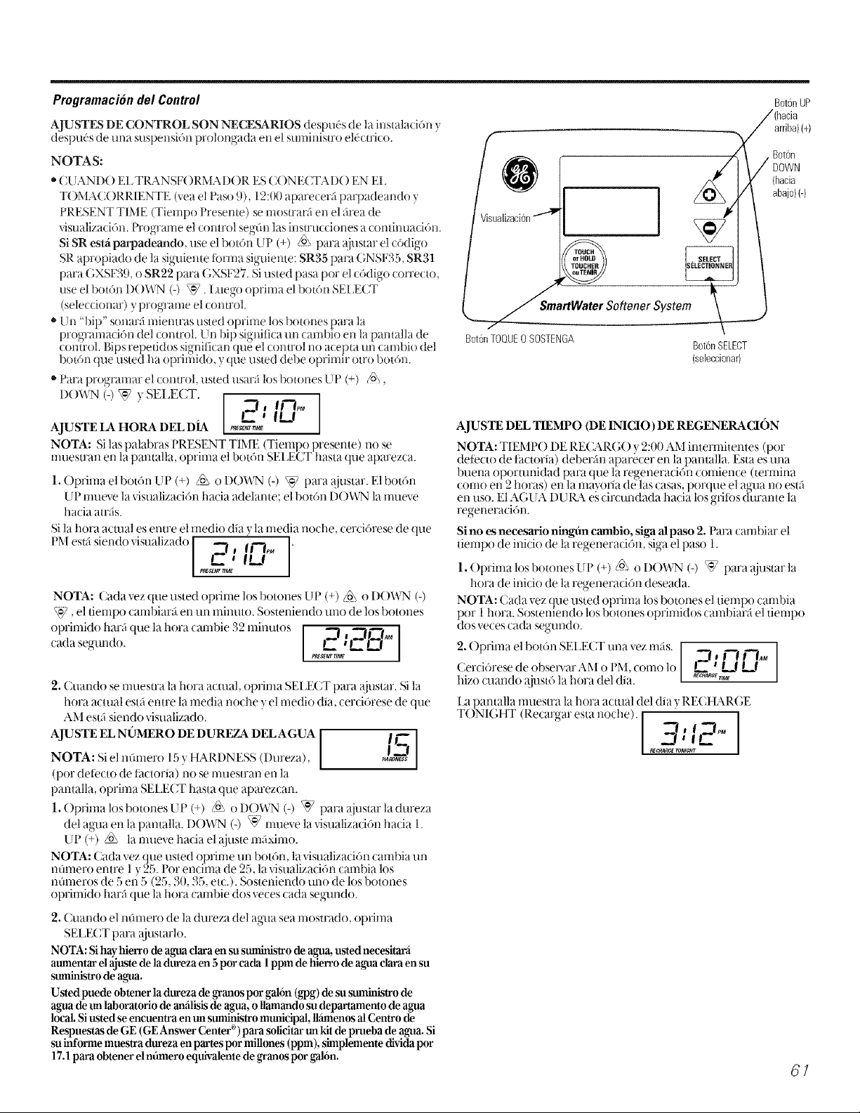
ProgramaciondelControl
AJUSTES DE CONTROL SON NECESARIOS despu(_s de la instalaci6n y
despu(.s de una suspensi6n prolongada en el suministro el,5(tri(o.
NOTAS:
• CUANDO EL TlL_NSF( )RMAD( )R ES CONE(;TAD() EN EL
TOMA( ()RRlENTE (yea el Paso 9), 12:00 aparecerfi parpadeando y
PRESENT TIME (Tiempo Presente) se mosu'a_ en el _irea de
visualizad6n. Programe el control segfin las instrucciones a continuaci6n.
Si SR estfi parpadeando, use el bot6n UP (+) _ pard ajustar el c6digo
SR apropiado de la siguiente torma siguiente: SR35 parD GNSF35, SR31
parD GXSF39, o SR22 parD GXSF27. Si usted pasa por el c6digo correcto,
use el bot6n D()WN (-) \*7. Ixmgo oprima el bot6n SEI_ECT
(seleccionar) yprograme el control.
• Un "hip" sonarfi mientras usted oprime los botones pard la
progTamaci6n del control. Un hip significa un cambio en la pantalla de
comrol. Dips repetidos significan que el control no acepta ttl-icambio del
bot6n que usted ha oprimido. ) que usted debe oprimir otro botdn.
"ParD programar el control, usted usarti los botones UP (+) _,
DOWN y ECT. r-rt I-tn'°
AJUSTE LA HORA DEL DIA ,,_%"_
NOTA: Si las palabras PRESENT TIME (Tiempo presente) no se
rnuestran en la pantalla, oprirna el boron SEI£CT hasta que aparezca.
1. ()prima el bot6n UP (+) _ o 1)()'_%I (-) _ parD aiustar. El b()t6n
LIPrnueve la visualization hacia adelante; el botOn I)( )_\q',Jla mueve
hacia atnis.
Sila hora actual es erure el medio diD)la rnedia noche, cercidrese de que
PM estfi siendo visualizado ___1_] I I_![f'--6M"
PgEsggr ntv_
NOTA: Cada vez que usted oprirne los botones UP (+) _ o I)( )'O,T,l(-)
, el tiernpo carnbiarfi en url illill[lt(L SosteMendo lnao de los botones
cada°l)rinlid°harfi que la h°ra carnbie 32 nlinut°s[segau-l(to. _s_--I_'_,_' I._ )"'l' _"__I_AM [
2. Cuando se muesu'a la hora actual, oprima SEIJECT pard ajustar. Si la
hora actual estfi entre la media noche y el medio diD, cerci6rese de que
AM eslfi siendo visualizado.
AJUSTE EL NOMERO DE DUREZA DEL AGUA [ h=
NOTA: Si el namero 15 )HARI)NESS (Dureza), ] _£_
(por detecto de titctoria) no se muestran en la
pantalla, optima SEI £CT hasta que aparezcan.
1, ()prima los botones UP (+) /_ o D()WN (-) _ parD ajustar la dureza
del ag_laen la pantalla. D( YO,?,I6) _] mueve la visualizaci6n hacia 1.
UP (+) /o\ la mueve hacia el ajuste maxim().
NOTA: Cada vez que usted oprime un botdn, la visualizad6n cambia un
nfimero entre 1 ', 25.1 or encima de _5, la visualizaci6n cambia los
nOmeros de 5 eli 5 (25, 30, 35, etc.). Sosteniendo uno de los botones
oprimido harfi que la hora cambie dos veces cada seglmdo.
2. Cuando el nOmero de la dureza del aDm sea mostrado, optima
SE'LECT parD ajustarlo.
NOTA: Sihay hielTo de ag_ claraen su suministro de agua, usIed necesitara
atmmnIar el aj uste de la dm'eza en 5por cada 1ppm de hierro de ag'ua clm'aen su
stmfinistro de agua.
UsIed puede obtenerla dureza de granos por galdn (gpg) de su stmfinistro de
agua de tm laboratorio de amilisis de agua, ollamando su departamento de agua
local.Si listed se encuentra en tm suministro municipal, II_mnos alCentro de
Respuestas de GE (GE Answer Center®)pard solicitar un kit deprueba de agua. Si
su informe muestra dureza enpates por millones (ppm), simplemente divida por
17.1pard obtener elnfimero equivalente de granos por gal6n.
Botc3nUP
/(hacia
"N/arriba) (+)
/ DOWN
/
Visualizacion
,rtWater Softener System_
Bot6nTOQUE0 SOSTENGA
AJUSTE DEL TIEMPO (DE 1NICIO )DE REGENERACJON
NOTA: TIEMPO DE RECAR(;O y 2:00 AM intennitentes (pot
detecto de tactoria) deben_n aparecer en la pantalla. Esta es una
regeneration.
Sino es neeesario niIgfin eanbio, siga al paso 2. ParD cambiar el
tiernpo de inicio de la regeneraci6n, siga el paso 1,
1. ()prima los botones UP (+)/o\ o DOWN (-) _ pard ajustar la
hora de inicio de la regeneraci6n deseada.
NOTA: Cada vez que usted oprima los botones el tiernpo carnbia
por 1hora. Sosteniendo los botones oprirnidos cambiar_ el tiernpo
dos veces cada segundo.
2. ()prima el bot6n SEI_ECT una vez rnfis. _1 a i""[ rl,,,,,
Cercidrese de obsep,_ar AM o PM. como 1o I_ t I_! k.I
hizo cuando _tiust6 la hora del diD. _ "_
1_apantalla muestra la hora actual del diD) RECHAR(;E
T()NI(;HT (Recargar esta noche). I
_E mNJG_T
Bot6nSELECT
(seleccionar)
7"i, I TJJ,,_
"-i, Ir-
(hacia
abajo)(-)
f Boton
I
61
Page 62

Instruccionesde instalacionpasopor paso.
Procedimientosde desinfeccion
Paracompletarla instalacidn,sigalos procedimientosde desinfecciSnsiguientes.
En la tiibrica sees Qfidadoso para mantener el descalcificador de aglla limpio y desinlectado. Ix/s materiales usados para constmir el
descalcificador rl(/contarnirlaFfirl rli irlteCtar_]n SUsurnirlistI'O de ag'ua rli Ca[lsaF_tn que se tibrllle o (rezca bacteria. Sirl embargo, durante el elwJO,
el almacenanliento, la irlstalaci6n y la operaci6n, algim tipo de bacteria podria penetrar el descalcificador. Pot esta r_6n, el siguiente proceso
de desirltecci6n se sugiere despuds de la irlstalacidrl.
NOTA: ta desinfeccion es recomendada pot la Asociacion de Calidad del Agua.
[_ Cerci6rese de cornpletar todos los pasos de instaklci6n, illclu) elMo la programaci6n de sincronizacidrL
[_ Vacie 3/4 de onza aproximadarner_te de doro casero 5,25 % (Clorox. Iinto. Bo Peep. White Sail. Eagle, etc.) en la sMmuera. Consuhe la
ilustracidr_ en la pfigina 58.
_]IMPORTANTE: ( )prirna y sostenga oprirnido por 3 segurldos el bot6n TOUCH/HOLD(toque/sostenga)para comenzar una regeneraci6n
inrnediata. Recharge Now (recarg_le ahora) aparecerfi intermiter_te en la pantalla, El cloro es llevado hacia y a travds del descalcificador
de agua.
[_]Si despuds de la desinteccidn, el aglla de algm-_ode los gritos de la casa tiene un sabor salado o tiene un color ligero, esto es un preservativo
del tanque de resina. Abra los gritbs de ag_la fi'ia descalcificada pot unos minutos hasta (tue el agua se aclare.
NOTA:Cuando la regeneraci6n anterior termina, el suministro de ag'ua FRIAde su casa estfi completamente descalcificada inmediatamente. Sin
embargo, su calentador de ag'ua estfi llerlo de agua dura ) a lnedida (lue el aKua calierlte va) a sierldo usada, el calentador se llenarfi corl ag'ua
descalcilicada. Cuar_do toda el agua dura sea reempl_ada en el calentador de agua, el agala caliente _ el ag_mrnezclada calierlte v fl'ia, estarfin
colnt)letamente............... descalcilicadas 'Siusted desea agua descalcificada........... inmediatarnerlte des')u(,si_de la re_ene_'acidrl....... anterior (kene)lO_m del
calentador hasta que el aglla salga fl'ia.
A_VERTENC_A: Siusted drena e_ca_ermld_r de agua_ tenga cuidad_ extrern_ ya que e_aglra ca_ierlte _ p(_dria quemar. Apague e_
calentador de aglla antes de proceder con el drem!je.
ESPE C1FIC_&CIONES/DIMENSIONES
Capacidad considerada*
Cantidad de capacidad de resina aha
(lbs/cu. pies)
Tamafio nominal del tanque de resina
(pulg. diam x ahura) 8 x 40 9 x 40 9 x 40
Ritmo de flujo de servicio (gpm) (ver etktueta de consideraci6n para
l)ureza rnSxima del suministro de agama(_ _)
l)ureza rnfixima de surnirfistro de aglla (ppln)**
Limites de presidn de aglla (rain - infix, psi)
Caida de presi6n al ritmo de fluio de servicio
(psig)
Telnperatura m_xima del aglla (°F)
Ritmo de flujo mfiximo del suministro
de aglla (pgm)
Ritmos de thljo del ciclo de regeneraci6rl (gpm)
Llenar (t]u)o al tanque de la sal)
Enjuagado lavado (fltljo hacia
I_avado regresivo drenado)
Sakmdo }
Enjuagale rfipido
_: 121pill( I)_t ltle lle,,_lda _tcabo us_llldo b{ )]il_ls g'l'Hdo C]OF{) de sodio c(nno saI l_(_enel31dol}l.
':* 121cm_tidad de hierro rem()vido puede'_tl"iar _'g{in las ctmdicion¢ s. IUs¢ Diamond (:l)S[ill Red,Oul o Super Iron OuI, lo (lue nKjorarfi kl removida d¢l hi€m).
(;()nstlh¢ la s( cci6n timpieza del Hierro del Agua. '
o-9o-
GXSF27 GNSF35 GXSF39
(yeaetiqueta de consideracidn de la scc
para descalcificadores de aglla)
36,4/,7 48,4/,93 52,5/1
descalcilicadores de agua)
100 100 100
5 6 8
20-125 20-125 20-125
15 15 15
120 120 120
3 3 3
,3 ,3 ,3
,l 9 ,20 20
,12 ,16 ,16
1,8 2,( 2,(
1,8 2,( 2,(
entrada_alida
t8 _'t'* ] _"_-'18 l't'*
tl ]'U
[
)or merlos dams.
wl '2"
62
Page 63

Acerca de/sistema de desca/cificacion de agua.
Servicio
Cuando el sistema des( al(ificador de agua est_ l)roportionando agua des(akifi(ada, a esto se le llama
"Serxicio". Durante el seF_icio, el agua dura fluye desde la mber_a de agua prindpal de ]a casa hacia el sistema
de Descalcificaci6n de agua. En el interior del tanque del sistema de Des( al( ifi( aci6n de agua hW una pe]icula
o capa compuesta de miles de resinas plastic:as dimimlms. Cuando el agua &ira pasa a mlv4s de ]a capa, cada
dimimlta resina atrapa los minera]es &lros. A esto se le llama intercambio de iones. Es (omo un iman
auayendo y atrapando meta]es. Entonces, el agua sin minerales &lros (agua descalcificada o agua blanda)
fluye hacia la casa desde el sistema de descalcificaci6n.
Despu4s de un periodo de 6empo, la capa de resina se obsuuye o se samra (:onlos minerales &lros y debe ser
limpiada. Esm limpieza es llmnada regeneraci6n, o recargado. I.a regeneraci6n ( omienza alas 2:00 AM (ajuste
por detecto) pox el control del sistema de descalciticaci6n de agua, y consiste en cinco etapas o ci( los. Elias son
FILL(I/enado),BRINING(procesodesalado),BRINERINSE(enjuaguede aguasalada),BACKWASH(lavadoregresivo)
y FASTR/NSE(/avador@ido).
Circunva/acion automatica de/agua dura durante /a mgeneracion
En (asos de emergen(ia, el agua dura est_ disponib]e Sin embargo, usted debe evitar usar agua CAUENTE
hacia la casa durante los ciclos de regeneraci6n, porque el ealentador de agua se Ilenara con agua dura.
tlenado
E1agua disueha en agua es llacnada salmuera. I_asalmuera es necesaria para liml)iar los minerales duros
de las dinlilmtas parttculas de resina. Para %rmar la salmuera, el agua flwe hatia el interior del tanque de sal
&rotate el periodo de llenado.
Procesodesalado
Durame el proceso de sala(lo, la sahnuera se desplaza del _rea del tanque de alma(enamiento de la sal ha(ia
el mnque de la resina. I_asalmuera es el ageme de limpieza necesmio pma rem()ver los minerales &lros de
la capa de resina. I_os minerales &lros y la salmuera son des( argados hacia el al( amariHado.
I_a boquiHa y el Venmri (rean una suc(i6n para mover la salmuera, mameniendo un Fi[iI_o t_lL!ybajo paIa
oblener la resina de limpieza (on la menor (antidad de sal.
Enjuague de agua salada
Despu4s de que una cantidad de salmuera premedida es usada, la %Mfia de salmuera se cierra. El agua
cominfia flwendo en la misma lrayectoria que &lrame el proceso de salado, exceplo por el flujo de salnmera
dis( ominuado. I_os minerales &lros'' la salnmera fluyen del tanque de resina hacia el al( amarillado.
tavado mgmsivo
]Durante el lavado regresivo, el agua x_aia Hacia Arriba a m_x4s del tanque de resina a un thljo de ritmo rapid(),
purgando el hierro acumulado, el sucio vlos sedimemos desde la capa de resina hacia el ak:anlariHado.
Enjuague rapido
E1 lavado regresi_ o es seguido por un flll io de agua r_pido Hacia Abajo durante el tanque de resina. E1flujo
rapido purga la salmuera del fondo del tanque, y rellena el tanque de resina.
A continuaci6n del eniuague rapid(), el sistema de descaMficaci6n de agua regresa al serx_cio de agua
descaMficada.
83
Page 64
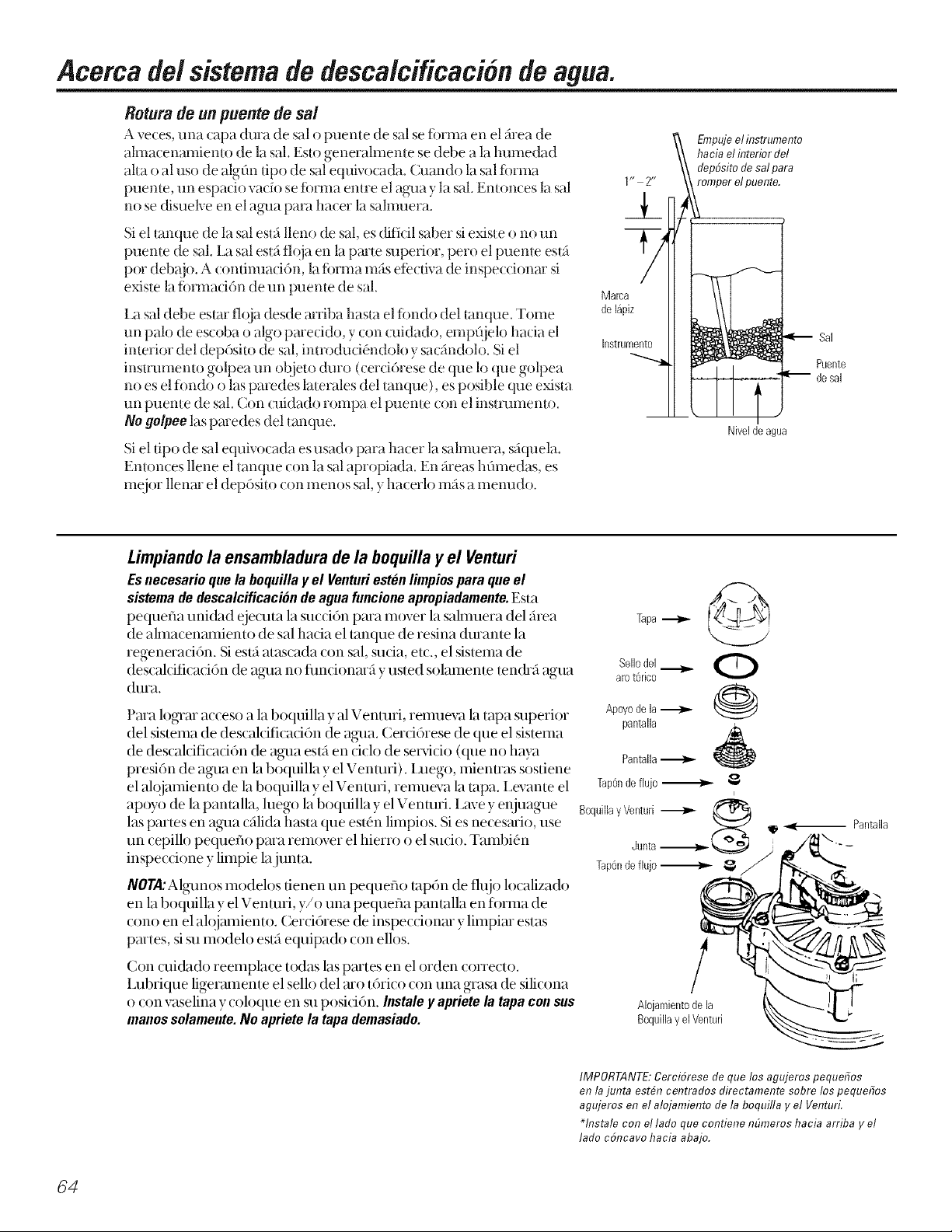
Acercade/sistemadedesca/cificaciondeagua.
Rotura de un puente de sal
A veces, una capa (Jura de sal o lmente de sal se iorma en el _rea de
ahnacenamiento de la sal. Esto generalmente se debe a la lmmedad
alta o al uso de algOn tipo de sal equivocada. Olando la sal fi)rma
puente, un espacio ratio se torma emre el agua y la saL Emonces la sal
no se disuelve en el agua paxw ha(er la salnmera.
Si e] tanque de ]a sal esta Hem) de sal, es dificil saber si existe o no un T4
pueme de sal. [_i sal esui floja ei1 la parle superior, pero el puente est_
pot debajo. A (onfinuati6n, la forma ross eff'(fiva de inspe(( ionar si
existe la forma(i6n de un pueme de sal. Mama
I.a sal debe estm floja desde arfiba basra el fimdo del tanque. Tome
un palo de es(oba o algo parecido v con cuidado, empQ}elo hacia el
interior del dep6sito de sal, introduci4ndolo ysacandolo. Siel Instrument0
instmmento golpea un objeto dmo (cerci6rese de que lo que golpea "_
no es el fimdo o las paredes laterales del [an(]ue), es posible que exista
un puente de sal. (_on (uidado ionlpa el pueme (Oil e] instrumento.
No go/pee ]as paredes del Ianque.
Si el fipo de sal equix ocada es usado para hacer la sahnuera, s_quela.
Entonces llene el tanque con la sal apropiada. En _reas hflmedas, es
me)or llenar el depGsito (on menos sal, y ha(erlo m_s a menudo.
de15pJz
1 r* 2**
;/
hacia el interior del
Empujeel instrumento
dep6sito de salpara
romper elpuente.
I
Niveldeagua
Sal
Puente
Limpiando la ensambladura de la boquilla y el Venturi
Esnecesarioquela boquillay el Venturiestenlimpiosparaqueel
sistemadedescalcificaciondeaguafuncioneapropiadamente.Esta
pequefla uni&ld eje(uta la sucti6n pma mover la salmuera del _hea
de almacenmniento de sal hada el mnque de resina duranm la
regenerad6n. Si esl:i atascada con sal, suda, etc., el sistema de
descalcificaci6n (D agua no flmcionm_ y usted solamente ten&a agua
dura.
Pma logrm acceso a la boquilla yal Venmfi, remueva la tapa superior
del sistema de descalcificad6n de agua. Cerd6rese de que el sislema
de descaldficaci6n de agua esui en dclo de servicio (que no haya
presi6n de agua en la boquilla y el Venmfi). I_uego, mienuas sostiene
el alojamienm de la boquilla y el Venmfi, renmeva la tapa. I_evante el
apoyo de la pantalla, luego la boquilla y el Venmfi. I_avey enjuague
las partes en agua c_ilida hasta que esl(Snlimpios. Si es necesmio, use
un cepillo pequeflo pma rem{)ver el hierro o el sudo. Tambi4n
inspeccione y limpie lajunta.
NOTA:Algunos modelos fienen un pequeflo tap6n de flujo localizado
en la boquilla y el Venmfi, y/o una pequefla pantalla en fi)nna de
cono en el alojmniento. Cerci6rese de inspecdonm y limpim estas
pmtes, sisu modelo esl:i equipado con ellos.
Con cuidado reemplace todas las pmtes en el orden correcto.
I_ubfique ligermnente el sello del mo t6fico con una grasa de silicona
o (on vaselina y (oloque en su posici6n. Instaleyaprietelatapaconsus
manossolamente.Noaprietela tapademasiado.
Tapa
SeRedel
arot6fico
Apoyode la
pantalla
Pantalla
Tap6ndeflujo
Boquilla¥Venturi
Alojamientodela
Boquilla y el Venturi
@
O
@
i
Pantalla
!
64
IMPORTANTE:Cerci6rese de que los agujeros pequefios
en la junta est#n centrados directamente sobre lospequefios
agujeros en el alojamiento de la boquilla y el Venturi.
*hTstale con ellado que contiene nOmeros hacia arriba yel
lado c6ncavo hacia abajo.
Page 65

Operationnormal, panta/la de control
Durame la opera(i6n normal, la hora a(mal del dia y AM o PM se muema en el _irea de la pantalla de (onuoL
Cuando la (ompuladofa de demanda determina que una regene_(iGn es ne(esaria, el mensaje RECHARGE
TONIGHT(recargueestanoche)(omienza a parpadea en1;tpanmlla (on lahora a(mal. RECHARGETONIGHT
(recargue esta noche) _3_2 _ parpadea hastaelmomenu) de iniciode lapr6xh'aaregeneraci6n,cuando
cambiar_i a RECHARGENOW(recargue ahora), lo cual parpadear_ basra que la regeneraciGn termine.
Caracteristica: Controles opcionales de mcargado
A _eces, es posible que usted desee o necesita una
generaciGn iniciada manuahnente (recarga). Dos
ejemplos:
[] Usted ha usado ross agua que de cosmmbre
(hu4spedes en la casa, lavado adicional, etc.) y
usted quiz_s se quede sin agua descalcificada antes
de la pr6xima generaci6n.
[] Usted no rellen6 el [anque de almacenamienlo
(till SHE
RECHARGETON/GHT(reoargueestanoche) 3:J2-
Oprima (nosostengaoprimido)elbot6nde
TOUCH/HOLD(toque/sostenga).RECHARGETONIGHT
(recargue esta noche) (omienza a parpadear en el _rea
de la panIalla de conuol. Una regeneraci6n ocurrir_
en el pr6ximo ini(io de regeneraci6n preajustada.
Si usted decide cancelar esta regeneraciGn, toque
el IlliSlllO boIoI1 llna _ez nlas.
RECHARGENOW(reoargueahora) _.!12"
Use una de loscaracterisdcas siguientes para
conlei1z_tr [ilia regeneratiGn imne(lialamenle, o en
el prGximo ini(io de regenera(iGn preajuslada.
Oprima y sostenga oprimido el bot6n de TOUCH
(toque)oHOLD(sostenga)basraque RECHARGENOW
(reoargueahora)(omien(e ai)arpadem en la pantalla
de control. El sistema de des(al(iiica('i6n de agua
(omienza una regeneraci6n inmediata y, (:uando
termine en unas dos horas, usted ten(ha un m_evo
suministro de agua descalcificada. Una vez haya
ini( iado, usted no Dlede can( elar la regeneracidn.
Caracteristica: Memoria de/proorama
Si el suminisno el4ctri( odel sistema de
descalcificaci6n de agua es inlermmpido, la panlalla
de conuol estara en blanco, pero el conuol manliene
la hora (one( Ia pot seis horas apro_madamenle.
Cuando el suminisuo es rest;mrado, usted tendr_i que
reajustar el dempo presente solamente si la
visualizaci6n esta pmpadeando. Todos los otros
@isLes se mantienen y nunca requieren seTajustados
Sila hora est,1intermitente despu4s de una
intermp(i6n prolongada en el suministro el4ctri( o,
el sistema de des( alciiicaci6n de agua continfia
trabajando como deberia pava proporcionarle agua
des( alciiicada. Sin embargo, las regeneraciones
po&ian o(:urrir en el momento del dia equivocado
hasla que usted reajuste el control a la hora conecta
del (lia.
a no set que usted desee ha(er algOn (ambio.
Caractoristica/Semicio: OiagnGsticos eloctronicos automaticos
I.a computadora de control [iene una flmci6n de
diagn6sdco antom_idco del sislema el4cuico (excep[o
para la energia de enuada y el medidor de agua). La
computado_J monitorea que los componentes
eleclr6nicos y circuitos fimcionen (orrectmnente. Si
o(:urre un real tm_cionmniento, el c6digo de error
aparece en la panlalla de control.
La tabla en C6digosdeError ErrU,3 muesua los
(6digos de errores que podrian aparecer ylos razones
posibles para coda c6digo. Mienuas un c6digo de
error es mostmdo, todos los botones de control dejan
de operar, excepIo el bot6n de SELECT(Selecoione).
SELECT(Seleooione) permanece en operaci6n para
que el t2cnico Dmda hacer los Oiagn6sticos
electr6nicosiniciadosmanualmenteyaislm m_isel
deibcto e inspeccionar el medidor de agua.
85
Page 66

Acerca de/sistema de desca/cificacion de agua.
Servicio:Caracteristicasy servicio del tiempode demandaelectronico
CI_DIGODEERRORVlSUALIZADO
POSIBLEDEFECTO
Pare remover un codi#odeerror: (1)Desconecte eltransformador
ERR01
• el motor no
funciona
• problemas en
el cableado o
en la conexi6n
hacia el
interru ptor
• interruptor de
posici6n
• control (PWA)
(2)Corrija el problema.
(3)Conecte otra vezel transformador
(4)Esperepor Iomenos 6minutos. El c6digo de error
regresar# si la razdn del c6digo de error no ha sido
corregida.
ERR02
• interruptor
de
posici6n
• control
(PWA)
ERR03 ERR04
• motor no
funciona o
problemas
enel
cableado
• control
(PWA)
• interruptor
de
posici6n o
problemas
en el
cableado
• control
(PWA)
ERR05
• control
(PWA)
Servicio:Sincmnizador/Desca/cificador,pmcedimiento de inspection de servicio
Siusled no esI5re(ibiendo agua des(ak ifi( aria, yun (6digo de error no espreseniado, use el siguieme
procedh_fiemo para enconuar ]a fl]eme de] problema. Primero realice ]assiguiemes inspet:dones visuales.
INSPECCIONES
VISUALES:
CONTROLESTA
LAPANTALLADE
ENBLANCO.
_4Hay energia el_cuica enmmdo hacia el [omaconieme en el cual el nansf_)rmador de]
sislema de descalcificaci6n de agua esl_ conectado?
_Hay stfliciente salen el tanque de almacenamiemo? E1t}mque debe eslar lleno de
_l/5"al/2 de sal.
I_ 4Es[_ Ia %lx_lla de bypass de dest:ak:ificad6n dirigiendo el agua para el se_,icio de
descalcificadGn?
_1_ 4Esl_ la %Mfla de la manguera de drenaje abierla hada el &enaje, a no m_s de 8 pies
del descak:ificador, v no [iene ninguna obsmlct:i6n?
Si usted no encuentra el problema con la inspecciSn visual, continue m_s adelante.
ELCONTROLMUESTRAI
LAHORAYELDIA
EQUIVOCADOS,Y/O
ESTAINTERMITENTE
Inspeccionela
energ[ael6ctrica
haciael control
(interruptor,
transformador,
cableel_ctrico,y
todas las
conexiones).
ElSuministroEl_ctrico
hasidointerrumpido.
Reajustelahoracorrecta
I
deldia.
E:',
--, suM,.,STROOK
Investiguelaraz6nde la I
interrupci6nel_ctrica.
REPARESEGON
DEFECTVO
klevea cabo los
diagn6sticos
manualespara
verificarque
t0d0func_0na
c0rrectamente.
I
I
66
LAPANTALLADECONTROL
MUESTRALAHORAYEL
DIACORRECTAYNOESTA
INTERMITENTE
Llevea
cabolos
diagn6sticos
manuaes.
Page 67
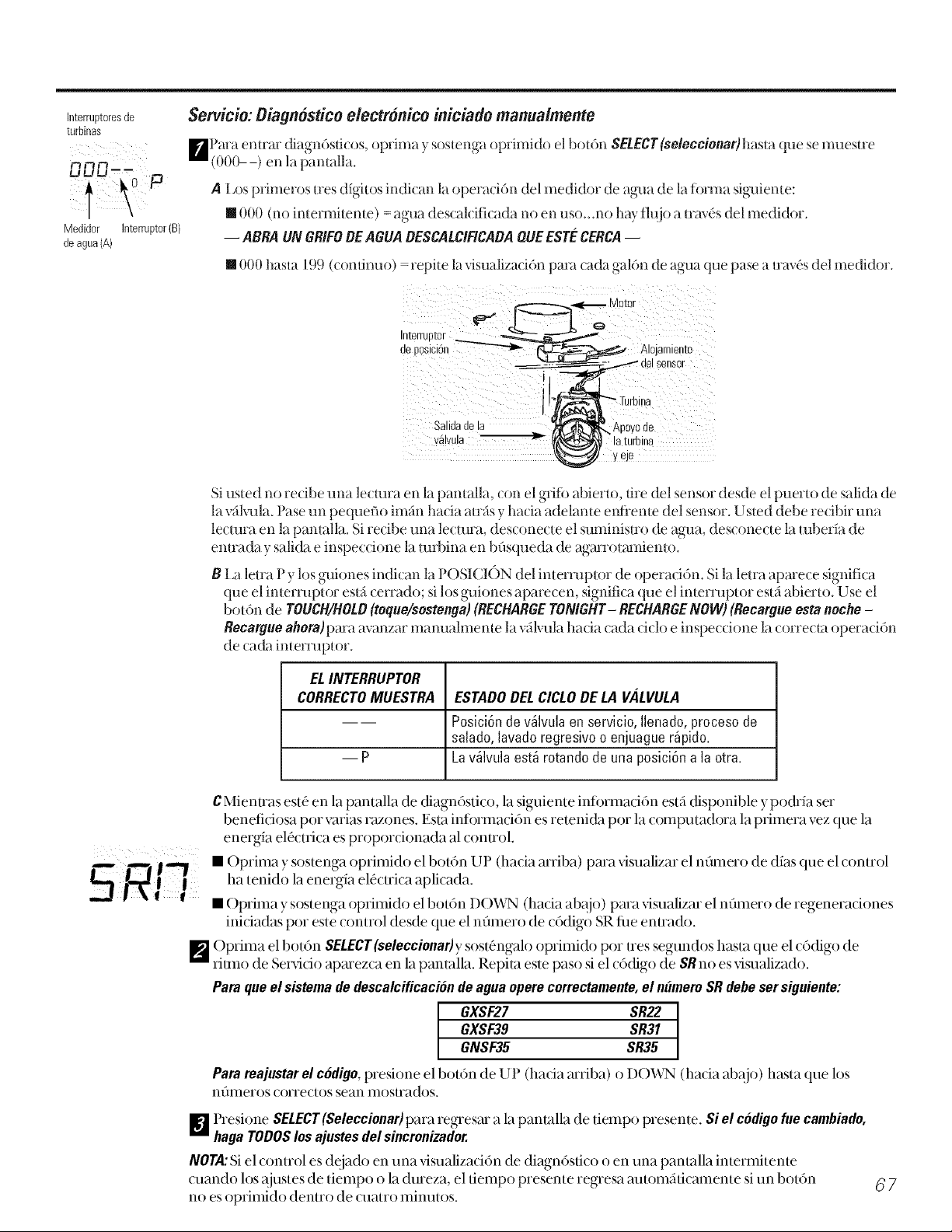
Interruptoresde
turbinas
Medidor Interruptor(B)
deagua{A)
Servicio:Diagnosticoelectronico iniciado manua/mente
BPara entrav diagnGsfi( os, optima y sostenga oprimido el botGn SELECT(seleccionar)hasta que semuestre
(000--) en la pamalla.
A I _osprimeros tres digit os indi( an la opera(iOn del medidor de agua de la fi)rma siguiente:
[] 000 (no intermiteme) = agua descak ifi( ada no en uso...no hay flujo a mwGs del medidor.
-- ABRA UN GRIFOOEAGUA OESCALCIFICAOA QUE ESTECERCA--
[] 000 hasla 199 (confinuo) - repite la visualizadGn para cada galGn de agua que pase a uav(,s del medidor.
d!Pgsi!i!n AL;ja;r:lise;_!
i
Salidadela _Apoyo de
v_lvula _ _ "la'turbina
y eJe
Si usted no recibe una lecmra en la pantalla, con el gri% abierto, fire del sensor desde el puerto de salida de
la wilvula. Pase un pequeflo im_n hacia auSs y hacia adelame e_dieme del sensor. U sted debe recibir una
lecmra en la pamalla. Si redbe una lecmra, desconecte el suminisuo de agua, desconecle la mber_a de
enuada y salida e inspeccione la mfl)ina ei1 b0squeda de a_arrolanfieilto.
B La letra P y los guiones indican la POSICI()N del intermplor de operaciGn. Si la letra apmece significa
que el inlenlipt()r esl_ cerrado; si los guiones aparecen, significa que el intermptor esl5 abierto. Use el
boIGn de TOUCH/HOLO(teque/sestenga) (RECHARGETONIGHT- RECHARGENOW) (Recargue esta neche -
Recargue ahora)para avanzar mawaalmente 1;iv_lvula hacia (ada (i(h/e inspe( (ione 1;ic(/rre( ta (/peraci6n
de cada interpaptor.
ELINTERRUPTOR
CORRECTOMUESTRA
ESTADOOELCICLODE LA VALVULA
Posici6nde%lvula en servicio,Ilenado,procesode
salado,lavadoregresivoo enjuaguer_pido.
--p
La%lvula est_ rotandode unaposici6na la otra.
CMienuas est(_en la pantalla de diagn6stico, la siguiente infi)rmad6n esta disponible y pochia set
benefidosa pot varias razones. Esla infi)rmaci6n es remnich pot" la computadora la primera vez que la
energia elOctrica es proporcionada al conuol.
• Optima y sostenga oprimido el bot6n UP (ha(ia arriba) para xdsualizar el nflmero de dias que el (onuol
ha tenido laenergia el(_(tri(a aplicada.
• Optima y sostengaoprimido elbot6n DOWN (hacia ab_{io)para visualizar el nflmero de regeneradones
inidadas pot estecontrol desde que elnflmero de c6digo SRtim enuado.
[] Optima el bot6n SELECT(seleccionar)ysost,fingalo oprimido pot Ires segundos hasta que el c6digo de
ritmo de Servicio aparezca en la pantalla. Repita este paso si el (6(figo de SR no es visualizado.
Paraqueel sistemadedescalcificaciondeaguaoperecorrectamente,el numemSRdebesersiguiente:
GXSF39 SR31
GXSF27 SR22 I
GNSF35 SR35
Paramajustarelcodigo,presione el botGn de UP (hacia arriba) o DO_,,\_ (hacia aba.io)hasta que los
nflmeros (orrectos sean mosu'ados.
[] Presione SELECT(Seleccionar)para regresar a la pantalla de tiempo presente. Si el codigo fue cambiado,
hagaTOOOSlosajustesdelsincronizador.
NOTA:Siel (onuol es deiado en una xdsualiza( i6n de diagn6sfi(o o en una pantalla interlnitente
cuando los ajustes de tiempo o la dureza, el fiempo presente regresa automaficamente si un bot6n
no esoprimido denuo de (:laatrominutos.
67
Page 68

Acercade/sistemadedesca/cificacidndeagua.
Servicio:Inspecci6n manualdel avance do/a regoneraci6n
Esta inspet d6n verifica la opera(i6n apropiada del motor de la vfilvula, del llenado del tar_que de la salrauera, extra(d6n de la salmuera, l'itmos
de tluio de regeneraci6n v otras fundones del controlador, l'rimero, lleve a cabo las inspecciones iniciales vel Diagnostico eloctrdnico iniciodo
manualmente. "
NOTA:I.a pantalla de conu'ol debe mostrar el tiempo de rnanera estable (no intemfitente).
_ l'resione el botdn TOUCH(toque) o HOLD(sostetNa) per tres segtmdos. RECHARGENOW (reoa_ue ahora) comienza a parpadear mientras el
sistema de descalciticaci6n de agua enu'a el ciclo de llenado de regenerad6n. Remueva la cubierta del depdsito de la sahmlera ,,, usando una
linterna, observe el agala de llenado entrando hacia el tanque de la salmuera. Si no hay agata entrando al tan( ue. bus( tie una b()quilla
obstruida, el Venmri'; el tapdn de thljo de llenado, o la tuberia de la sahnuera. (;onstflie ia secci6n para el Cuidado g timpioza dol Sistema do
Oescalcificacidn deAgua.
F,_ Despu(.s de obsel_,ar el llenado, presione el bot6n TOUCH(toque) o HOLD(sostenga)para mover el Sistema de descah:ifi( a(i6n de ag'ml hada
el proceso de salado. Un tlujo lento de ag-Llahacia el dreriaje debe comenzar. Verilk tie que la exu'acd6n de la salmuera del tanque de la
salnmera alurnbrando con {ma linterna hacia el dep6sito de la salmuera y observando un goteo evidente en el nivel de liquido durante un
per'it)do de tiempo extenso.
NON: Cerci6rese de que no es tm pnente de sal el que estti evitando el contacto con la sal. Consnlte la secci6n de Cuiflaflo y fimpieza flol Sistema do
OescalcificaciSndeAgua.
Si el sistema de descalcificaci6n de agua no extrae salmuera, inspeccione:
• Que la boquilla y/o el Venmri no est(,n su(ios o detectuosos. • Que no exista un sello de la boquilla y/o el Venmri dafiado.
• Que la boquilla y/o el Venmri no estdn bien asentados en lajunta. •()tro detecto de la vSl,mla interna (sello del rotor, rotor ydisco,
• Que rio exista un drenaje restringido (inspecciorie los ajustes del araridela de onda, etc).
drerl_!je )la marlgllera).
NOTA"Si la presi6n..... del sistema de agua es baja., una mang-aera,.......elevada podria causar presi6n regresiva, , evitando.... la extracci6n de la sahnuera.
l)e.nuevo.., el bot6n TOUCH(toque) o HOLD(sostenga).l)ara, mover.el <sistema...... de descalciticaci6n.. . de<..,.a¢ua hacia el.lavado reoTesivo<..,< . Bus(:ltleun
_ t]ulo rapldo de agua de la mang-aera de dren_!le. Un thllo lento lndlca que hay un dlstrlbuldor superior obstruldo, un tap61-1de tlulo de lavado
regresivo, o la mariguera de drenaie.
_'_ l'resiorie el bot6ri TOUCH(toque) o HOLD(sostenga) para mover el sisterna de descalcitTcacidri de ag'aa hacia eriiuague rtipido. De rmevo, busque
tm tluo r_pido. Permita que el sisterna de descalcificacidri de ag'aa eniuague per trees minutes para purgar dualquier salrnuera que ha,.a
qued_;ido eri el tanque de resina durarite la prueba del ciclo del proceso de salado.
_ l'ara regresar el sistema de descalciticaci6r_ de agua a sela-icio, presione el b()t6n TOUCH(toque) o HOLD(sosteuga).
Cuidadoylimpieza del sistemade descalcificacion de agua.
Inspeccione el nivel de almacenamientode la sal y el rellenado
Se necesita sah-nuera (sal disueha en agua) para cada regeneraci6n. E1agua para hacer la sah-nuera es medida cuando enu'a al _rea de
ahnacenamiento de la sal a travds de la v_1lvuladel sistenia de descalciticaci6n de ag_Ja) el control. Sin embargo, usted debe manteuer el suministro
de/tanqueconsat
Cuandorellenarconsaklnspec(ione el nix,elde la sal unas semanas despu('s de hater la instalad(,n del sistema de descal( iii(aci(,n de agua ', (ada
semana despues. Rellene (uando el tanque de la salmuera esm de 1/3 a 1/2 lleno. En areas humedas es meier llenar (on mends sal ', ha( erlo m_s
fl'ecuentemente. Nunca permita que el sistema de descalciticacidn de aglla use toda la sal antes de usted rel'lenarlo. Sin sal, pronto tendr_1 agua
dura.
s s" : s': "s <i'" "=:" "".... . _,. cot e (ra os _ • S, ), _ So& ,(' g ;_S.
Use salesdeslstentasdedes(alclhc,tclorideag-uaso!amente, porlomenos !1!1,5_ pur__,' R'""nn li" m slFllT_ B( [IT_ SAI ,R I_
S()I AIl. No use sal en roca, en bloques, granuJada, #itde helado (para desoongelar hiMo) Ellas contienen suciedad y sed mentos, o pasta ) terra, y
crear_in problemas de mantenimiento.
_tl PRECAUCION:Sal desoaloificadora de agua DOnaditivos que remueven el hierro: Alglmas sales podrian tenet aditivos para ayudar el sistema
de descalciticaci6n de agua con el hierro en el sunfinistro de ag'aa. Aunque este aditivo puede aytldar a mantener limpid el sistema de
descalciticaci6n de agu_i, el mismo tambidn puede crear gases corrosives que debilitan ) acortan la vida de las partes del sistema de
descalciticacidn de agua. (;,E solamente recomienda el use de la marca de sal Diamond Cl) stal ':'Red.()uti
Comolimpiar el hierro de su sistema de descalcificacion de agua
Su sistema de des(al(-itk a( i(nt de ag_Ja toma la dureza de los materiales (cakio v magnesio) ,, la exuae del agua. Tambi(.n, puede controlar una
cantidad considerable del hierro del "ag'ua clara" (Vea la secci6n de Oirectrices"de _specificaciones). Cori hierro de ag_.lacl:;lra,el ag'aa de un grito
es clara ctialtdo se coloca el-ititt vase al principle. De 15 a 50 nlitttltOS l-ltfistarde, el a<_tia €omiel-iZa a ponerse turbia o a cal-libiar a tin color roi0
ladrillo. U n sistema de descalciticaci6n de ag'aa no romueve el hierro que causa que _1 ag'aa se tome mrbia o que adquiera el color reid ladrillo
cuando sale del g-rile (llamada agua rojo ladrillo). Para exu'aer el hierro de esta agua se requiere un filtro u OtTOequipo.
GE recornierida que se useri las rnarcas de sal I)iarnond Cr', staF: Red.Out" con aditivo lr(m Fighter :_:para avudar a rnanterier la capa de resina
lint -tiadel hierro Sisu surniriistro de a "aa tiene hierro de i_ma clara es necesario ( tie usted l_m )ie )eft( dlcarnerite la ca )a de resina GE
! " " ' " r . : -,,g -,s ° ' 1 , 1 1 ..... ., 1 . ; -
(( _ O ) )
descaldlicada eriu'e limpieza y limpieza.
IMPORTANTEfEsirnportante rnezcla[ el lirnpiador de la capa de resina c()na<_tia(siga las irisu'ucdones del t{d)ricante) vvadarlo en el tubode
depfisitode lasalmuem(yeapfig-ina58) vproteda a regerierar el desca](ifica_lor im:nediatarnerite. No vierta el ]impiad()r de la (apa de resiria con
la sal, )a que no ser_itan eti( iel:ite en su hu-i( i(,n de lin<ipieza de la resina, y puede ( ausar dafios al des(alcificador si se deja en el tarique de la sal
per uri perk)do de tiernpo prolorigado debido a que gases corrosives se tormarian.
68
Page 69

AntesdeIlamarpara solicitar servicio...
Consejos para la identificaci6n y soluci6n de averfas
iAhorre tiempo y dinero! Revise la tab& en esta p#gina primero y quiz#s
no tenga que Ilamar para solicitar servicio.
NO HAYAGUA DESCALCIFICADA - Problemas mrs comuanes:
Inspeccione I0siguiente antes de Ilamar para solicitar servicio
• Nivel de sal en el descalcificador no hay suficiente. E1tanque debe estar lleno hasta por lo menos 1/3.
• I_avfilvula de b_T)assse est_ en la posici6n de "B_0ass"-debe estar en la posici6n "Servicio." I _apalanca
debe estar en la posici6n OUT (fllera).
• I,os ajustes de la dureza demasiado bajo-Inspeccione los ajustes de la dureza en el conu_fl. Verifique la
dureza del suministm de again. I,a dureza del aglm puede variar durante el afio. Vea la secci6n
ProgTamaci6n del Conu_)l.
• Un puente de sal, donde el agua no est_ en conlacto con la sal (yea la secci6n Rotura de un Puente
de Sal.)
Problema Posible causa Que hacer
No hay agua
descalcificada
El grifo o d accesorio donde la muestra
fue tomada no es_ conectado al sistema
de agua descalcificada.
NOTA:Cerci6rese de que la muestra no
es tomada de un grifo que mezclaagua
descalcificada con agua dura. Por ejemplo,
un grifo de unasola palanca de la cocina, si
la tuber& del agua fr& de esegrifo estfi
conectada al agua dura.
No hay s_ en el tanque de
almacenamiento o existe un puente
de sal en el tanque de almacenamiento
El transformador est_ desconectado en el
tomacorriente de la pared, o el cable del
descalcificador no es_ conectado. Un
fusible es_ fundido o se desconect6 en el
circuito el6ctrico hacia el tomacorriente.
El tomacorriente es_ en un circuito que
no puede ser desconectado.
La vfilvula de bypass manual es_ en la
posici6n de bypass.
Lavfilvulade la manguera de drenaje es_
ata_ada, obstruida, devada a una
posici6n demasiado alta u obstruida de
alguna forma.
"Para conservar sal, el instalador puede que haya aislado alglmos
grifos (grifos fuera de la casa, inodoros, etc.) del sistema de
descalcificaci6n. A parfir de la salkla del sistema de descalcificaciGn
de agua, rastree la traye( toria de la tuber_a de la casa. Si el agua
descalcificada no estfi cone( tada dire( tamente a un grifo o _ccesorio
donde a usted le gllstar_a que estuxiera conectado, p6ngase en
contacto con tm plomero.
"Inspeccione el mnque pot un puente de sal, o siel mnque est,1vac_o,
llene otra vez el mnque con sal. ()prima (pot tres seglmdos) el
bot6n TOUCH/HOLD(toque/sostenga)para dar inicio a laregenerad6n
yrestaurar el suministro de agua blanda.
"Inspeccione para cercio_'arse de que no ha habido una inmrmpci6n
energ,_tica hada el descalcificador de ag_la debido a alglmas de estas
condiciones y conija segfln sea necesario. Una vez restaurada la
energ_a, observe la visualiza( i6n en la (ara del plato y lea la Se( (i6n
sobre laMemoria del Program&
NOTA:Eltomacorriente para el interruptor del descalcificador debe estar
constantemente conectado para que no pueda ser desconectado
accidentalmente.
"Cerci6rese de que la palanca de la %lvula de bypass se encuentra en
la posk:i6n con'e(ta, con el bot6n en la posi(i6n ()UT (afuera).
Observe las instmcciones en la etiqueta en el extremo de la palan(a.
"Cualquier restricci6n en esta manglmra de drenaje puede prevenir
la opera(i6n apropiada de la boquilla } el Venturi } redu(ir o evitar
l_t 1o111_tde la salmueFa durante las regeneraciones.
La boquilla y el Venturi estainsucios,
ensamblados incorrectamente o dafiados.
"Consuhe lasinstmcciones para Limp&rlaBoquillay el Vonturi.Con la
presidn del ag_mdes(onectada del sistema de descal(ifi(addn de
agua, desarme la ensambladura de laboquilla. [nspeci6nela,
l[mpiela y _eemplace cualquier parm seg%msea necesario. Cualquier
panicula extrafia, ralladura, muesca, etc., en los pasajes pueden
impedir la operaci6n.: Cerci6_ese de que los agu.jeros pequehos en
lajunta est6n cenn'ados directamenm sob_e los pequehos aglljeros
en el alojamiento.
69
Page 70

Antes de Ilamarpara solicitar servicio...
Problema Posible causa Quehacer
A veces el agua Usar agua caliente mientras el • Esite usar agua caliente mientras el descalcificador de aglla est5 en
est# dura descalcificador de agua estai en el proceso el proceso de regeneraci6n porque el calentador de ag_la se
de regeneracidn rellenar5 con agua du_'a. Consulte la Secci6n de Circunvalaci6n del
Los niveles del numero de dla-eza del "Prcsione y liberc el bot0n SEThasta que HARDNESSaparezca en la
control estVfinmuybajos, panmlla. Aseg_'lrcse de que el nfmmro que aparcce es el mismo que
Los granos de dm'eza en su agua ban • I_a dureza del aglm puede cambiar con el paso del dempo,
aumentado especialmenm cuando se nata de aglm de pozo. Para inspeccionar,
Elagua se siente Ausenda de dla-eza de materiales "Esto es normal.
resbalosa despu#s
de la instalacion
del sistemade
descalcificacion
de agua.
Elsistema de E1 sistema de descalcificad6n de agua • No usa mnm sal para regenerarse, es muy eficienm.
descalcificacion es una unidad de "demanda"
de agua no est#
usandoninguaa
sal Posible puente de sal "Consulte la Secci6n de Consojos para las Instrucciones do OperaciOn.
Agua DuraAutom#tica durante la Regeneraci6n.
los granos reales por dureza en un gal6n de su suministro de a_lla.
Consulte la secci6n Controlsi se necesita un cambio en los niveles.
hfig'ale una prueba al aglla en un laboc, m)rio de anfilisis o llame a su
l)eparmmento local de Aglm. A.jusm el sincronizador segfin sea
necesario. Consulm laTabla de Regeneraci6n.
Boquilla o Venturi posiblemente "Consulte la Seccidn de Consojos para las Instruccionos do Oporacidn.
obstruidos
El agua tiene un Agua _idda en tuberias de cobre "Inmediatamente solicim que se le haga una prueba al ag_m.
color azul
despues de que el _'k ADVERTENCIA: NO tome de esa agua hasta que el problema haya
sistema de sido corregido.
descalcificacion
de agua fue
instalado
El sistema de La tm'bina dd medidor es_ atascada
descalcificacion
de agua no est# El cable del sensor estaicorroido
regenerando
No hay energia el_ctrica en la unidad
Defecto mecanico
Agua turbiaonIn Combinacidn de agua descalcificada y
cristaleria (on los demasiado detergente
lavaplatos
automaticos)
Agua sabea sal
despuesde la
instalacion
Insufidente lavado regresivo y
enjuagado.
"I_lame y solicim se_Mcio.
"Llame y solicim se_Mcio.
"Inspeccione el inmrruptor de circuito o los filsibles.
• I_lame y solicim se_Mcio.
• A esto se le llama grabado do aguafuorto yes permanente. Paca edtar
que esto su(eda, use menos detergente si usted tiene ag'lla
descalcificada. I_ave la cristale_:_a ell el ciclo mils corto que los pueda
limpiar.
• ()prima y sostenga ot)rimido el botdn TOUCH/HOLD(toque/sostenga)
hasta (lue RECHARGE(recargar)se vuelva intermitente para iniciar
una regene_'acidn.
"Despuds de que el ciclo de regeneraci6n haya sido completado
(aproximadamenm 2 horas), haga circular aglm a trav(.s de los gritos
paca ptugar el agua salada.
7O
Baja presidn del agua
Manguera de drenaje restringida
', Inspeccione la presidn; debe esmr a un mfilimo de 20 psi.
"I Jmpie y reconecm la manglmm.
Page 71

Problema Posible caosa Que hacer
Lasparticulas
deresina
aparecenen el
aguapotabley
enlos
lavamanos
Un sonido qne
osted puede
escnchar
El agoa tiene
borbnjas de
agoa y esta
torbia
Un error de
codigo en el
control
Distribuidor a_ietado * l_lame pare solMtar se_icio.
Agua circulando desde la unidad hacia el "Esto es n(_rmal
drenaje
Se introdujo aire en el sistema despu_s de "Esto desaparecerfi despuds de hal)er funcionado un tiempo.
la instalacidn
El cableado podria haberse aflojado en el
control
" l)esconecte el tc,msformador.
• Remueva la mpa del conm)l, lit)ere los (:lips en los lados.
"Inspeccione en bfisqueda de conexiones de alambres o tal)leros
electrdnicos o inmrruptores que puedan estar flojos. Recondcmlos
si es necesafio.
"Reensaml)le la tapa del control.
• Conecte el tcanslbrmador.
"Espere seis minutos para que el error de cddigo desaparezca.
"Si el error de cddigo no desaparece, llame pare solicitor servicio.
7/
Page 72

Listadepartes.
4 _ ....--16
_ 14
4
56_ 55
56_
28
/
5
/
0
22._.....24-.,._
_""23
10
26-......_
72
Page 73

Listadepartes.
152
\
151
-_'- I38
/137
1331:
25
120
- 130
147
/
121
73
Page 74
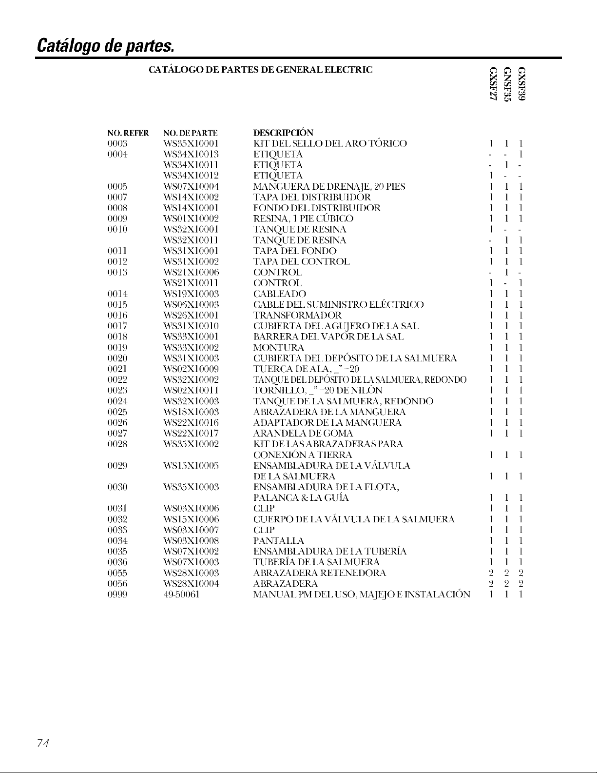
CatMogodepartes.
CA.TJkLOGO DE PARTES DE GENERAL ELECTRIC
NO.REFER
OOO3
0004
OOO5
0007
OOO8
OOO9
0010
O01l
0012
0013
0014
0015
0016
0017
0018
0019
OO20
0021
0022
0023
0024
OO25
0026
0027
OO28
OO29
OO30
0031
0032
0033
0034
OO35
0036
0055
OO56
0999
NO. DE PARTE
WS35X1000 l
WS34X10013
WS34X1001 l
WS34X10012
WS07X10004
WS 14X10002
WS 14X10001
WS01 X10002
WS32X10001
WS32X10011
WS3I Xl000 l
WS31 X10002
WS21 X10006
WS21 Xl0011
WS 19X10003
WS06X10003
WS26X10001
WS31Xl0010
WS33X10001
WS33X10002
WS31 X10003
WS02X10009
WS32X10002
WS02X10011
WS32X10003
WS 18X10003
WS22X10016
WS22X10017
WS35X10002
WS15XI0005
WS35X10003
WS03X10006
WS15X10006
WS03X10007
WS03X10008
WS07X10002
WS07X10003
WS28X10003
WS28X10004
49-50061
DESCRIPCXON
KIT DEI. SEI.I.O DEI.AROTORICO 1 1 1
ETIO.U ETA 1
ETI O.U ETA 1
ETIOU ETA l
MANGUEP_ DE DRENA.]E, 20 PIES 1 1 1
TAPA DEI. DISTRIBUIDOR 1 1 1
FONDODEI. DISTRIBUIDOR 1 1 1
RESINA, 1 PIECI_TBICO 1 1 1
TANO.U E DE RESINA 1
TANQUEDERESINA 1 1
TAPADEI.FONDO 1 1 1
TAPADEI. CONTROI. 1 1 1
CONTROl. 1
CONTROl. 1 1
(ABIJL_kDO 1 1 1
CABI,EDEI,SUMINISTROEI,(_CTRICO 1 1 1
TILhNSFORMADOR 1 1 1
CUBIERTA DEI,AGUJERO DEIA SAI, 1 1 1
BARREILh DEI,VAPOR DE IA SAI, 1 1 1
MONTURA 1 1 1
CUBIERTA DEI,DEPOSITO DEIA SAI,MUEIL_k 1 1 1
TUERCADEAIA,_"-20 1 1 1
TANQUE DEE [)El ()SIT() DE I_ SALMUERA, REDONDO 1 1 1
TORNII,I,O,_" -20 DENII,ON 1 1 1
TAN@JEDE IA SAIMUERA, REDONDO 1 1 1
AI'flL_XZ_XDERA DE IA MANGUEIL_k 1 1 1
ADAPTADORDEIAMANGIJEIL_ 1 1 1
AIL_KNDEIA DE GOMA 1 1 1
KIT DE IAS ABIL_KZ_KDEIL_KSI'AIL_K
CONEXION A TIERIL_K 1 1 1
ENSAMBIADUtL_K DE IA V/\I57UIA
DE IA SAI.MUEP_ l l l
ENSAMBIADUP_ DE IA FI.OTA,
PAIANCA&IAGUIA 1 1 1
(I.IP 1 1 1
CUERPO DE IA V/\I?_TUIA DE IA SAIMUEIL_k 1 1 1
CEIP 1 1 1
PANTAHA 1 1 1
ENSAMBIADUP_*_ DE IA TUBERIA 1 1 1
TUBERIA DE IA SAI.MUEP_& 1 1 1
ABIL_TADEtL_K RETENEDOIL_K 2 2 2
ABtL_KZ_KDEIL_ 2 2 2
MANUAl, PM DEI, USO, M_JE.]O E INSTAIACION 1 1 1
)
74
Page 75

Catalogodepartes.
CATJtLOGO DE PARTES DE GENERAL ELECTRIC
NO. REFER NO. DE PARTE
0025 WS18X10003
0101 WS02XI0012
0102 WS02X 10013
01 {)3 WS21 Xl {){){)3
01{)4 WS03X10009
0105 WS02X 10014
01{)6 WS3 lX10006
0107 WS03X 10010
01{)8 WS26X10002
0109 WS19X10004
0110 WS03X 10011
0111 WS 19X10005
0112 WS03X10013
0113 WS22X1 {){)2{)
0114 WS08X 10005
0115 WS03X10015
0116 WS22X10021
0117 WS03X10017
0118 WS15X10009
0119 WS03X10018
0120 WS03X10019
0121 WS15X10010
0122 WS03X10020
0123 WS22X10022
0130 WS35X10005
0132 WS22X10023
0133 WS03Xl{){)21
0134 WS03Xl{){)22
0135 WS03Xl{){)23
0136 WS26X1 {){){)3
0137 WS26X1 {){){)4
0138 WS26X10005
0139 WS02XI0015
0140 WS26X10006
014l WS02XI0016
0142 WS60X10001
0143 WS60X 1{){){)2
0144 WS60X 1{){){)3
0145 WS60X 1{){){)4
0146 WS28X1 {){){)5
0147 WS 19X10006
0150 WS03X10024
0151 WS15X10012
0152 WS03X10025
0153 WS60X10006
DESCRIPCION
ABRATADEIL_ DE IA MANGUEtL_K
TORNIII,O, #4 - 24 X 1-1/8"
ESPACIADOR
INTERRU PTOR
1L_SADOR DE EXPANSION
TORNII I,O, #10 - 14 X 2"
(U BI ERTA DE I A Vi\I _VUI A
A1L_KNDEI A DE ONDA
ROTOR Y DISC()
TAPA
SEII,O DEAR(-) TORICO 1.1" X 1.4"
I'ANTAI,I A DE APOYO
PANTAI i A
TAPON DE FIIJJO .l GPM
JUNTA BOQL!II I A/VENTURI
1L_NTAIIA CONICA
TAPON, FI,U]O DE II,ENADO, ,3 (d M
TU ERCA CONTERA
ENSAMBIADUIL_ DE IA BOQUIIIA/VENTURI
RETENEDOIL_
SEI,I,O DE AR( ) TORICO 1/4" X 3/8"
CU ERPO DE IA Vi\I,VUI A
RESORTE
TAPON DEI, DREN&JE DE IA SAI,
KIT DEI, SEI I,O
ADAt'TADOR DE I A MAN(;UEIL_ DE D_N&JE
ARO TORICO 5/8" X 13/16"
TAPON 1)E FII_JJO CONTROl, 1)E EN.JUA(;UE
CI3P
I,EVA & ENGK'_KNA.JE
RODAMIENTO
PI ATO DEI, MOTOR
TORNIII,O, #6 - 2{) X 3/8"
ENSAMBI ADUtL_K DEI, MOTOR
TORNIII,O, #6 - 2() X 7/8"
TU ERCA DE IN STAI A (ION
TUBO DE INSTAIACION
AIL_KNDEIA
CIdP
SENSOR DEI, AI Q]AMI ENTO
ENSAMBIADURA DE IA TURBINA YAPOYO
SEI,I,O, ARO TORICO
ENSAMBIADUtL_K DE IA V_a_I,VUIA DE 1WI}ASS
SEI,I,O, ARO TORICO
ADAI'TADOR
1
1 1
1
1 1
1
1 1
1
1 1
1
1 1
5
5 5
1
1 1
1
1 1
1
1 1
1
1 1
1
1 1
1
1 1
1
1 1
1
1 1
1
1 1
1
1 1
1
1 1
1
1 1
1
1 1
1
1 1
2
2 2
1
1 1
1
1 1
1
1 1
1
1 1
1
1 1
1
1 1
1
1 1
1
1 1
1
1 1
1
1 1
1
1 1
2
2 2
1
1 1
2
2 2
2
2 2
2
2 2
2
2 2
2
2 2
1
1 1
1
1 1
1
1 1
1
1 1
2
2 2
2
2 2
*NOTA:I,osC6digos en el Estado de Massachuseus requieren que la insmlad6n
sea eje{utada pot un plomero licendado y no permite el uso de la v_iMfla de
monmva. Pma la insmlaci6n use el C6digo de Plomeria 248 CMR del Estado de
Massachuseus.
75
Page 76

GarantiaGEparael Sistemade Besca/cificacibn deAgua
Servicio al Cliente. Para servicio, /lame a 800-GE-CARES
Todos los servicios de garantfa son proporcionados por nuestros Centros de Servicio de Factorfa, o un tbcnico autorizado de
Por el periodode:
Un afio
A part# de/a fecha de
la compra original
Tres afos El monitor electronico, si el mismo fitlla debido a detbctos de materiales o en la fi_bricad6n. Durante un
A partir de la fecha de periodo de tres a_os de garantia limitada, usted ser_ responsable por cualquier mano de obra o costos de
la compra original sex_-icio en su casa.
Diez afios Un gabinete de reposicion (el tanque de la salmuera), o un tanque deresina, si cualquiera de los dos falla
A partir de la fecha de debido a defe(tos de materiales o en lafhbrica(i6n. Dumnte un periodo de diez a#os de garantia
la compra original limitada, usted ser_ responsable por (ualquier mano de obra o (ostos de ser_d(io en su (asa.
Nosotrosremplazaremos:
Cualquierparte del Sistema de des(al(iti(a(i6n de agua (me falle debido a dele(tos de materiales o en la
fhbri(a(i6n. Durante un periodo de un an_ocompleto de _agarantia, (;E tambi_n le propor(ionar;i, de
manera gratuita, toda la mano de obra y ser_dcios en su casa para remplazar panes (lefecmosas.
Loque no esta cubierto:
• Viajes de servicio a su casa para ensefiarle como usar
el producto.
• Instalacion inapropiada.
• Fallas del producto debido a abuso, o uso del producto
indebido, o para usos comerciales.
• Filtros, membranas o baterias.
• Reemplazo de los fusibles de la casa o reajustes de los
circuitos de interrupcion.
• Dafio del producto causado por accidentes, incendios,
inundaciones o incidentes de fuerza mayor.
• Dafio incidental o consecuencial causada por defectos
posibles de este electrodom_stico.
Esta garantia es extendida al comprador original y a cualquier propietario posterior del producto comprado para uso en el
hogar dentro de EE.UU.EnAlaska, la garantfa excluye el costo de envio olos servicios de Ilamada a la casa.
Algunos estados nopermiten la exclusiSn o la limitaciSn de dafios incidentales o consecuenciales. Estagarantfa le da a
usted derechos legales especfficos, y quiz#s usted tenga otros derechos, los que variar#n de estado a estado. Para saber
cu#les son sus derechos legales, consulte a una oficina de asuntos del consumidor local o estatal oa p6ngase en
contacto con la oficina del Procurador General del estado (Attorney General).
Garante: General Electric Company.Louisville,KY40225
76
Page 77

Notas
77
Page 78

Notas
70°
Page 79

NumemsTelefonicosdeServicio.
GEAnswerCenter®(CentroderepuestasGE)8oo42_-2ooo
E1( entro de Respuestas (;E esta abierto 24 horas al dia, 7 dias a la semana.
0
Visftenos en la lnternet al: www.geappliances.com
ParaServiciosdeReparaci6nenel Hogar800-432-2737
E1servido experto de (;E se en_uenUa apenas auna simple llamada de distanda.
Serviciosde NecesidadesEspeciales800-626-2000
800-TDD-GEAC(800-833-4322)
(;E ofie(e, gratuitamente, un folleto para asistir en la planifi(ad6n de (odnas libres de barreras para
personas _on mox41idad limitada.
Contratosde Servicio800-626-2224
Compre un contrato de servicio de (;E mientras su garantia to(kr&l esta en etecto yrecibir_ un descuento
substancial. E1departamento de Servidos al Consumidor GE estara (fisponible despues de la fedm de expirad6n
de la garanda.
PartesyAccesorios800-626-2002
Aquellos indMduos que sepan c6mo &u servMo asuspropios electrodomOsticos pueden solMtm que seles
env_enpmtes o accesoriosen suscasas(Acepmmos Visa, MasterCmd y Discover).
Lasinstruccionescontenidasen este manualcubrenlosprocedimientosa serIlevadosa cabopor cualquier
usuario.Otrotiposerviciodebeser Ilevadoa caboporpersonal de servicio calificado.Sea precavido,ya que
hacerreparacionesinapropiadaspodria resultaren operacioninsegura.
Satisfacci6ndeServicio
Siusted no esl_ satistecho con el servido redbido pot GE:
Primero,p6ngase en conmcto con el personal que dio se_ido a su electrodom_stico.
Segundo, si afln usted no eslfi sadsti_cho, escriba todos los demlles-incluyendo su nflmero de teldtimo-a:
Manager, Customer Relations, GE Appliances, Appliance Prok, I,ouisville, KY 40225.
79
Page 80
Service TelephoneNumbers.
GEAnswerCente¢_ intheU.S.:800-626-2000
Tile (,E Ans_e_ (_ente_ is open 24 holn s a day, / days a week.
InCanada, contact: Manager, Consumer Relations, ( ;:ltlicoInc., 1Factoi)7 I,alle, Suite 31O,
Men(ton, N.B., El(; 9M3.
OR
Visit our Website at: wvvw.geappliances.com
In-HomeRepairServiceintheU.S.:800-432-2737
Expert (;E repair se_,i(e is only a phone (all away.
InCanada, (:all toll flee 1-866-777-7627.
SpecialNeedsServiceintheU.S.:800-626-2000
GE offers, tiee of charge, a brochure to assist in planning a bmrier-flee kitchen ti)r persons _dth limited mobility.
In the U.S.,call800-TDD-GEAC(800-833-4322).
In Canada,contact:
Manager, Consumer Relations, Cmn(o Inc., 1 Facto U I.ane, Suite 310, Mon(ton, N.B., E1C 9M3.
ServiceContractsintheU.S.:800-626-2224
l ur( hase a (,E sexual(e {ontra(t while your warranty Issull m efle(t and you ll re(ewe a substanual dis( ount.
(iE Consumer Se_4ce will still be there atier your warranty expires.
In Canada,call 1-800-461-3636.
PartsandAccessories/ntheU.S.:800-626-2002
Individuals qualified to se_x-i(etheir ()_1_appliances can have parts or accessories sent (fire(tly to their homes
(VISA, MasterCard and Discover cmds me accepted).
Instructionscontainedin thismanualcoverprocedurestobeperformedbyanyuser.Otherservicinggenerallyshouldbe
referredto qualifiedservicepersonnel.Cautionmustbeexercised,sinceimproperservicingmaycauseunsafeoperation.
In Canada,pleaseconsultyouryellowpagesforyourlocalCamconumber.
ServiceSatisfaction
If you are not satisfied with the se_-i(e y()u receive flom GE:
First,contact the people who se_wicedy()ur appliance.
Next, if you me still not pleased, in the U.S.,x_ite all the det:fils-including your phone number-to:
Manager, Customer Relations, GE Appliances, Appliance Prok, Louisville, KY 40225; or,
in Canada, to Director, Consumer Relations, Camco Inc., 1Facto U I_ane, Suite 310, Men(ton, N.B., E1C 9M3.
8O
Printed in the United States
 Loading...