

Page 1
0
Safetg information ............. 2
installation Instructions ...s-12
Step-bg-step instructions ....... 6-12
Operating Instructions
Breaking a salt bridge ............. 1/4
Cleaning the nozzle and
venturi assemblg ................. 14
Features ......................... !5
Service .................... 13, 16-18
Water softener sgstem ........ 16-18
Care and Cleaning ............ 19
Troubleshooting Tips ...... 20-22
ge.com
Water Softening
Sgstem
Model GXSF30H
Sistema Suavizante
de Agua
Consumer Support
Consumer Support ....... Back Cover
Parts list/catalog .............. 23-26
Warrantg (U.S.) ................... 27
Warrantg (Canada) ............... 28
Sgstem tested and certified bg NSF International against NSF/ANSI Standard 44 for the
chemical reduction claims specified on the performance data sheet.
Sistema probado g certificado par NSF International contra norma 44 de NSF!ANSI para las
afirmaciones de reducci6n de los productos quimicos especificadas en la hoja de datos de
funcionamiento.
Mode!o GXSFgOH
La secci6n en espafiol empieza en la p_gina 29
Write the model and serial
numbers here:
Model #
Serial #
To find these numbers, lift the
cover and look on the rim
below the control panel.
7283918 215Cl173P021
49-50177 06-06 JR
Page 2
IMPORTANT SAFETY INFORMATION.
READ ALL INSTRUCTIONS BEFORE USING.
;i WARNING!
For your safety, the information in this manual must be followed to minimize the risk of electric
shock, property damage or personal injurg.
SAFETYPRECAUTIONS
::Ji::Check and complg with gour state and local codes.
You must follow these guidelines.
::Ji::Use care when handling the water softening
sgstem. Do not turn upside down, drop, drag
or set on sharp protrusions.
?_:Water softening sgstems using sodium chloride
(salt) for recharge add sodium to the water.
Persons on sodium restricted diets should consider
the added sodium as part of their overall intake.
Potassium chloride can be used as on alternative
to sodium chloride in your softener.
?_:The water softening sgstem works on 24 volt-60 Hz
electrical power onlg. Be sure to use only the
included transformer.
iJi::Transformer must be plugged into an indoor
120 volt, grounded outlet onlg.
::Ji::Use clean water softening salts onlg, at least 99.5%
pure. NUGGET,PELLETor coarse SOLARsalts are
recommended. Do not use rock, block, granulated
or ice cream making salts. Theg contain dirt and
sediments, or mush and cake, and will create
maintenance problems.
::J_::Keep the salt hole cover in place on the softener
unless servicing the unit or refilling with salt.
WARN ING: DOnot usewith water that
is microbiologicallg unsafe or of unknown qualitg
without adequate disinfection before or after the
sgstem.
PROPERINSTALLATION
This water softening system must be properlg installed and located in accordance with the
Installation Instructions before it is used.
?_:Install or store where it will not be exposed to
temperatures below freezing or exposed to ang
tgpe of weather. Water freezing in the sgstem will
break it. Do not attempt to treat water over 100°R
::Ji::Do not install in direct sunlight. Excessive sun or
heat mag cause distortion or other damage to
non-metallic parts.
?_:Properlg ground to conform with all governing
codes and ordinances.
!;_:Use onlg lead-free solder and flux for all
sweat-solder connections, as required bg
state and federal codes.
?_:Softener resins mag degrade in the presence of
chlorine above 2 ppm. If gou have chlorine in excess
of this amount, gou mag experience reduced life
of the resin. In these conditions, gou mag wish to
consider purchasing a GEpoint-of-entrg household
filtration sgstem with a chlorine reducing filter.
A WARNING: Discard all unused parts
and packaging material after installation. Small
parts remaining after the installation could be
a choke hazard.
Thewater softening sgstem requires a minimum
water flow of three gallons per minute at the inlet.
Maximum allowable inlet water pressure is 125 psi.
If dagtime pressure is over 80 psi, nighttime pressure
mag exceed the maximum. Usea pressure reducing
valve to reduce the flow if necessarg.
READAND FOLLOWTHISSAFETYINFORMATIONCAREFULLY.
SAVETHESEINSTRUCTIONS
Page 3
nstructlons Model G×SF30H
iJns'a"a:ionIwaterso'tenin0systemI
I [_ Questions? Call 800.GE.CARES (800.432.2737) or Visit our Website at: ge.com I
WARNING: Read entire manual. Failure to follow all guides and rules could cause personal
injurg or propertg damage.
• Check with gour state and/or local public works department for plumbing codes. You must follow their
guides as gou install the Water Softening sgstem.
NOTE: Failure to complg with these installation instructions will void the product warrantg, and the
installer will be responsible for ang service, repair or damages caused therebg.
BEFORE BEGINNING INSTALLATION
Read these instructions completelg and carefullg.
• IMPORTANT - savetheseinstructions
for local inspector's use.
• IN PORTANT - Observeallgoverning
codes and ordinances.
• Note to Installer- Besure to leave these
instructions with the Consumer.
• Note to Consumer- Keep these instructions
for future reference.
• Proper installation is the responsibility of the
installer.
• Product failure due to improper installation
is not covered under the Warranty.
• A shutoff valve must be available or added near
the installation point.
IMPORTANT INSTALLATION
RECOMMENDATIONS
• In the Commonwealth of Massachusetts,
Plumbing Code 248 CMR shall be adhered to.
Consult with your licensed plumber.
• Useonlg lead-free solder and flux for all sweat-
solder connections, as required bg state and
federal codes.
IMPORTANT INSTALLATION
RECOMMENDATIONS (CONT.)
• Use care when handling the softener. Do not
turn upside down, drop, drag or set on sharp
protrusions.
Maximum allowable inlet water pressure is 125
psi. If daytime pressure is over 80 psi, nighttime
pressure may exceed the maximum. Use a
pressure reducing valve if necessary. (Adding a
pressure reducing valve may reduce the flow.)
The softener works on 24 volt-60 Hz electrical
power onlg. Be sure to use the included
transformer. Be sure the electric outlet and
transformer are in an inside location to protect
from moisture.
• See Where to Install the Softener section
for more details.
AWARNI NG:Do not use with water
that is microbiologicall9 unsafe or of unknown
qualitg without adequate disinfection before or
after the system. The water should be tested
periodicallg to verify that the system is
performing satisfactorily.
• Small parts remaining after the installation could
be a choke hazard. Discard safelg.
• Connect the softener to the main water supplg
pipe before or ahead of the water heater.
DO NOT RUN HOT WATER THROUGH THE
SOFTENER. Temperature of water passing
through the softener must be less than 120°R
Page 4
Installation Instructions
UNPACKING AND INSPECTION
Be sure to check the entire softener for ang
shipping damage or parts loss. Also note damage
to the shipping cartons. Contact the transportation
compang for all damage and loss claims. The
manufacturer is not responsible for damages
in transiL
Small parts needed to install the softener are
packaged either in a bag or on a cardboard
sheet. To avoid loss of the small parts, keep them
packaged until gou are readg to use them. Be sure
not to discard components hidden in packaging.
TOOLS AND MATERIALS REQUIRED
FOR INSTALLATION
• Pliers
Screwdriver
• Teflon tape
• Razor knife
o
Two adjustable wrenches
o
Additional tools may be required if modification
to home plumbing is necessarg.
In and out fittings included with the softener
are !" NPT male adapters. You should maintain
the same, or larger, pipe size as the water supplg
pipe, up to the softener inlet and outlet. Then,
use the necessarg adapters to connect the
water supplg to the !" NPT male adapters.
Use the included bgpass valve to install the
softener. The bgpass valve allows gou to turn off
water to the softener for servicing, but still have
water in the house pipes. The NPT male adapters
referred to above connect to the bgpass valve
with the included plastic clips.
WHERE TO INSTALL THE SOFTENER
Place the softener as close as possible to a
sewer drain, or other acceptable drain point
or standpipe.
It is recommended to keep outside faucets
on hard water to save soft water and salt.
Do not install the softener in a place where it
could freeze. Freeze damage is not covered bg
the warrantg.
Do not install the softener where it would block
access to the water heater or access to the main
water shutoff.
Putthe softener in a place where water damage
is least likelg to occur if a leak develops. The
manufacturer will not repair or pag for water
damage.
A &20-volt electric outlet is needed to plug in the
included transformer. The softener has a !0-foot
power cable. If the outlet is remote (up to !00
feet), use 18 gauge wire to connect. Be sure the
electric outlet and transformer are in an inside
location, to protect from wet weather. Be sure
the outlet is unswitched to prevent accidental
shutoff.
If installing in an outside location, gou must
take the steps necessarg to assure the softener,
installation plumbing, wiring, etc., are as well
protected from the elements (sunlight, rain, wind,
heat, cold), contamination, vandalism, etc., as
when installed indoors. Outdoor installation is
not recommended, and voids the warrantg.
Keep the softener out of direct sunlight.
The sun's heat mag distort non-metallic
parts and mag damage the electronics.
Use appropriate fitting/pipe material (i.e., copper,
brass, galvanized or CPVC) to connect the !" NTP
plastic adapters to the house plumbing.
If additional drain hose is needed for valve and
salt tank drains, it can be ordered from GE Parts
at 800.626.2002, part number WS07X!0004.
If a rigid valve drain is needed to complg with
plumbing codes, gou can bug the parts needed
to connect a 1/2" copper tubing or plastic pipe
drain. See Step 4.
Clean nugget or pellet water softener salt is
needed to fill the brine tank. See Step 8.
Page 5
Installation Instructions
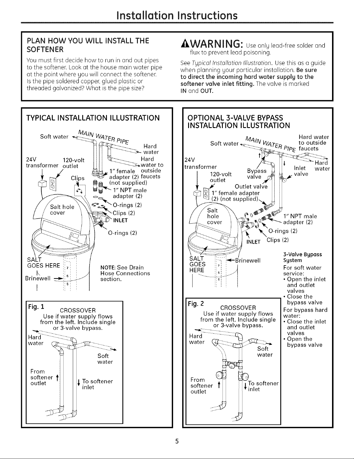
PLAN HOW YOU WILL INSTALL THE
SOFTENER
You must first decide how to run in and out pipes
to the softener. Look at the house main water pipe
at the point where gou will connect the softener.
Is the pipe soldered copper, glued plastic or
threaded galvanized2 What is the pipe size2
TYPICAL INSTALLATION ILLUSTRATION
-&WARNING: Use onlg lead-free solder and
flux to prevent lead poisoning.
See Typical Installation Illustration. Use this as a guide
when planning gour particular installation. Be sure
to direct the incoming hard water supplg to the
softener valve inlet fitting. The valve is marked
IN and OUT.
OPTIONAL 3-VALVE BYPASS
INSTALLATION ILLUSTRATION
Hard water
Soft water
24V Hard
transformer Inlet water
120-volt valve
outlet
to outside
Pip E faucets
Fig. 1
from the left. Include single
water
From
softener t
outlet
CROSSOVER
Use if water supply flows
or 3-valve bypass.
To softener
inlet
Soft
water
Fig. 2
from the left. Include single
Hard--.................::i-_-T.
water
From
softener t
outlet
CROSSOVER
Use if water supply flows
or 3-valve bypass.
?Tn_e_°ft ener
1" NPT male
"q_"'--add pter (2)
_, O-rings (2)
INLET Clips (2)
3-Valve Bgpass
Sgstem
For soft water
service:
• Open the inlet
For bypass hard
water:
• Close the inlet
• Open the
Soft
water
and outlet
valves
Close the
bypass valve
and outlet
valves
bypass valve
S
Page 6
Installation Instructions
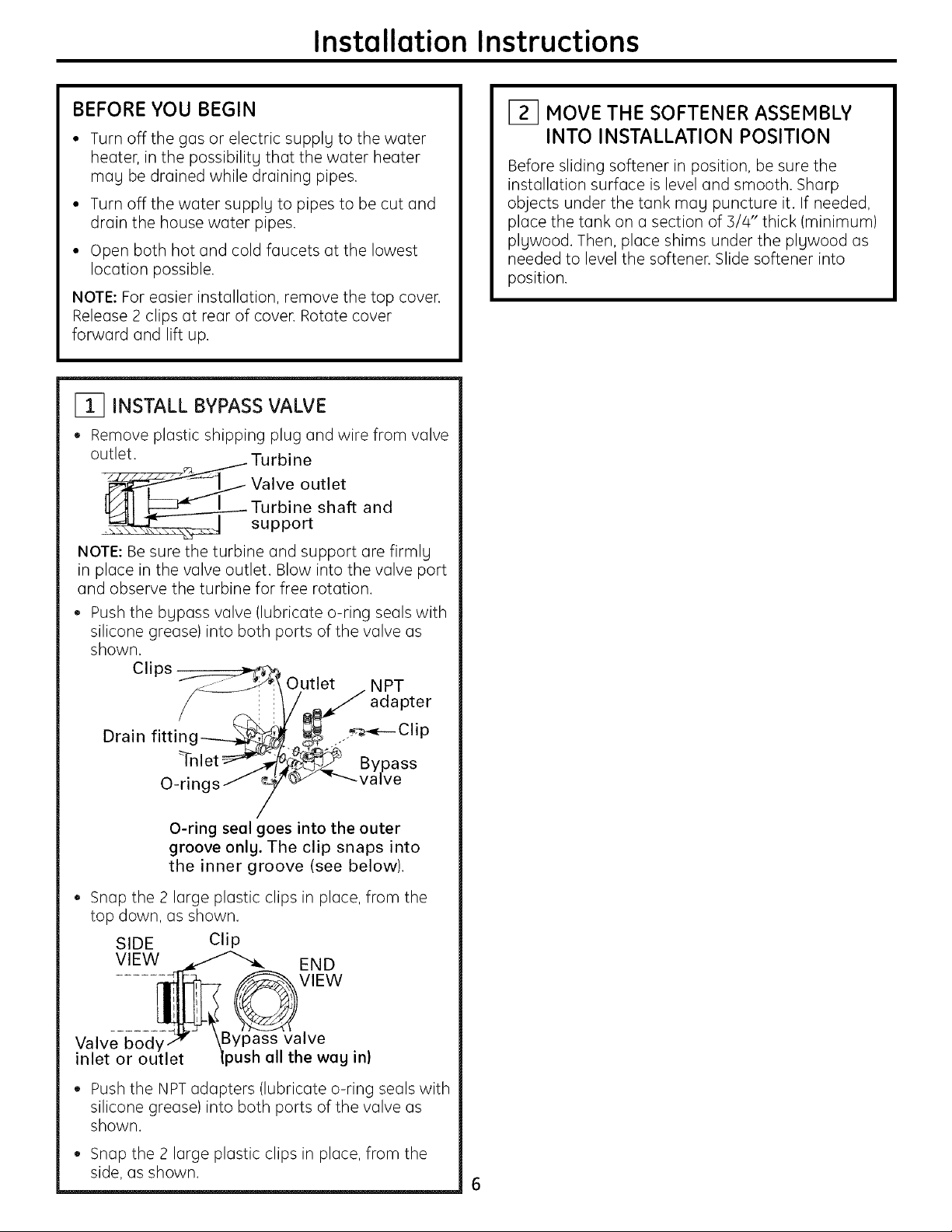
BEFORE YOU BEGIN
• Turn off the gas or electric supplg to the water
heater, in the possibilitg that the water heater
mag be drained while draining pipes.
• Turn off the water supplg to pipes to be cut and
drain the house water pipes.
• Open both hot and cold faucets at the lowest
location possible.
NOTE: For easier installation, remove the top cover.
Release 2 clips at rear of cover. Rotate cover
forward and lift up.
I_1 INSTALL BYPASS VALVE
• Remove plastic shipping plug and wire from valve
outlet.
"'_ Valve outlet
• _J support
NOTE: Be sure the turbine and support are firmlg
in place in the valve outlet. Blow into the valve port
and observe the turbine for free rotation.
• Push the bgpass valve (lubricate o-ring seals with
silicone grease) into both ports of the valve as
shown.
Clips __
Turbine
Turbine shaft and
:! Outlet . NPT
[_ MOVE THE SOFTENER ASSEMBLY
INTO INSTALLATION POSITION
Before sliding softener in position, be sure the
installation surface is level and smooth. Sharp
objects under the tank mag puncture it. If needed,
place the tank on a section of 5/4" thick (minimum)
plgwood. Then, place shims under the plgwood as
needed to level the softener. Slide softener into
position.
Drain fitti K_ _clip
n_g_ I/ _ adapter
_nlet --_-, _._ Bypass
O-rings_ '_ "'---valve
/
O-ring seal goes into the outer
groove only. The clip snaps into
the inner groove (see below).
• Snap the 2 large plastic clips in place, from the
top down, as shown.
SIDE Clip
VIEW END
VlEW
Valve bod, Bypass valve
inlet or )ush all the wag in)
• Push the NPT adapters (lubricate o-ring seals with
silicone grease) into both ports of the valve as
shown.
• Snap the 2 large plastic clips in place, from the
side, as shown. 6
Page 7
Installation Instructions
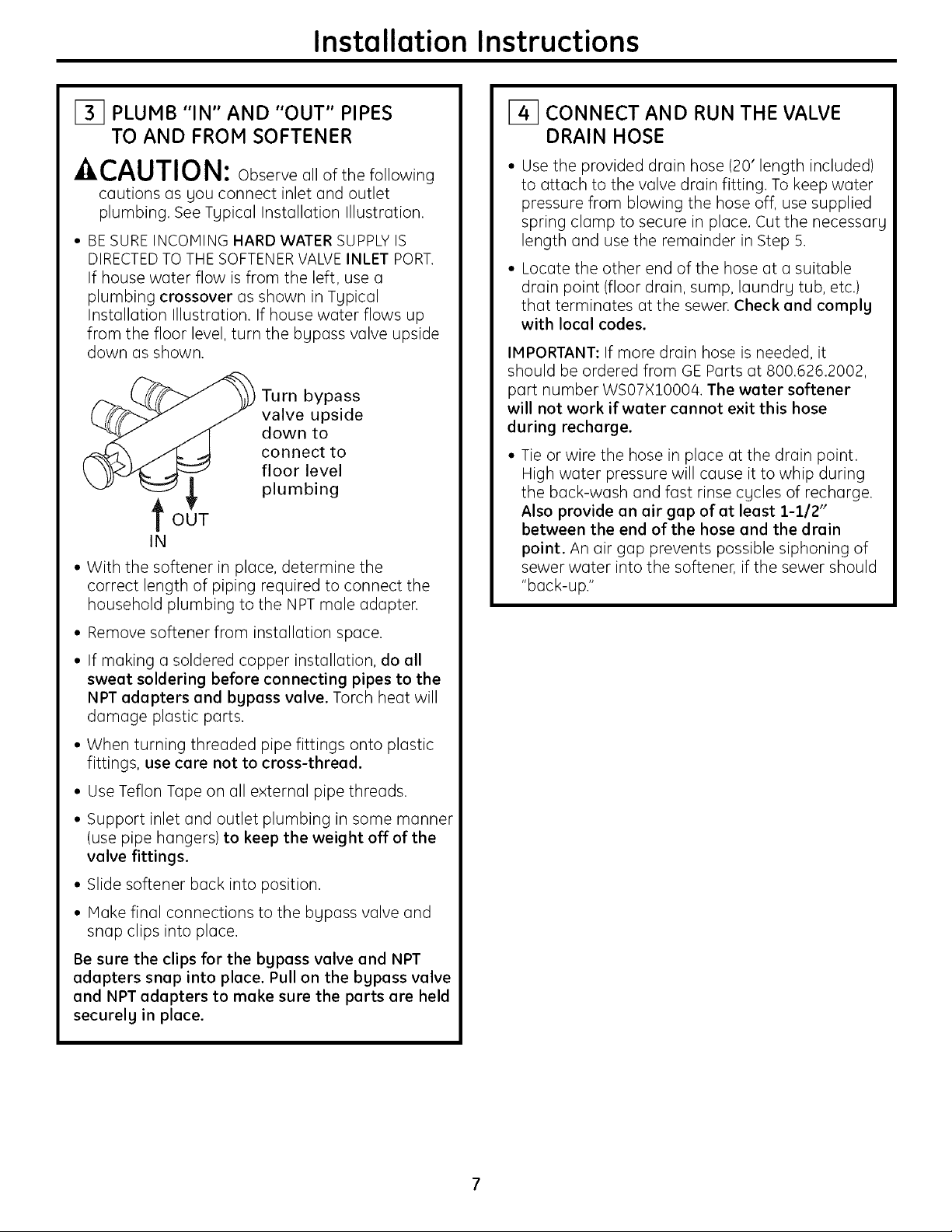
131 PLUMB "IN" AND "OUT" PIPES
TO AND FROM SOFTENER
,CAUTION: Observe all of the following
cautions as gou connect inlet and outlet
plumbing. See Typical Installation Illustration.
• BE SUREINCOMING HARD WATER SUPPLY IS
DIRECTEDTO THE SOFTENER VALVE INLET PORT.
If house water flow is from the left, use a
plumbing crossover as shown in Tgpical
Installation Illustration. If house water flows up
from the floor level, turn the bgpass valve upside
down as shown.
Turn bypass
valve upside
down to
connect to
floor level
plumbing
tOUT
IN
• With the softener in place, determine the
correct length of piping required to connect the
household plumbing to the NPT male adapter.
141 CONNECT AND RUN THE VALVE
DRAIN HOSE
Use the provided drain hose (20' length included)
to attach to the valve drain fitting. To keep water
pressure from blowing the hose off, use supplied
spring clamp to secure in place. Cut the necessarg
length and use the remainder in Step 5.
Locate the other end of the hose at a suitable
drain point (floor drain, sump, laundrg tub, etc.)
that terminates at the sewer. Check and complg
with local codes.
IMPORTANT: If more drain hose is needed, it
should be ordered from GE Parts at 800.626,2002,
part number WS07X10004, The water softener
will not work if water cannot exit this hose
during recharge.
• Tie or wire the hose in place at the drain point,
High water pressure will cause it to whip during
the back-wash and fast rinse cgcles of recharge.
Also provide an air gap of at least 1-112"
between the end of the hose and the drain
point. An air gap prevents possible siphoning of
sewer water into the softener, if the sewer should
"back-up."
• Remove softener from installation space.
• If making a soldered copper installation, do all
sweat soldering before connecting pipes to the
NPT adapters and bypass valve. Torch heat will
damage plastic parts.
• When turning threaded pipe fittings onto plastic
fittings, use care not to cross-thread.
• Use Teflon Tape on all external pipe threads.
• Support inlet and outlet plumbing in some manner
(use pipe hangers) to keep the weight off of the
valve fittings.
• Slide softener back into position.
• Make final connections to the bgpass valve and
snap clips into place.
Be sure the clips for the bypass valve and NPT
adapters snap into place. Pull on the bypass valve
and NPT adapters to make sure the parts are held
securely in place.
Page 8
Installation Instructions
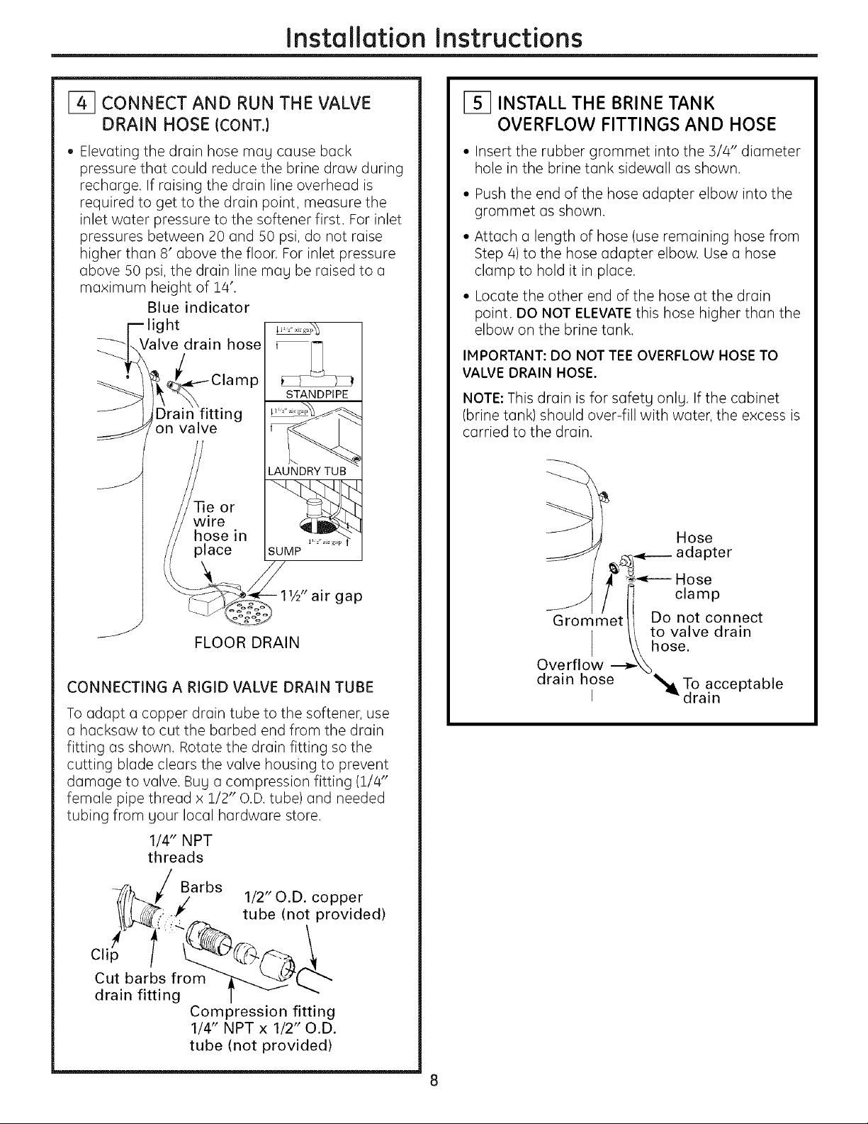
F_ CONNECT AND RUN THE VALVE
DRAIN HOSE (CONTJ
• Elevating the drain hose may cause back
pressure that could reduce the brine draw during
recharge. If raising the drain line overhead is
required to get to the drain point, measure the
inlet water pressure to the softener first. For inlet
pressures between 20 and 50 psi, do not raise
higher than 8' above the floor. For inlet pressure
above 50 psi, the drain line may be raised to a
maximum height of 14'.
Blue indicator
light
[_ INSTALL THE BRINE TANK
OVERFLOW FITTINGS AND HOSE
• Insert the rubber grommet into the 3/4" diameter
hole in the brine tank sidewall as shown.
• Push the end of the hose adapter elbow into the
grommet us shown.
• Attach a length of hose (use remaining hose from
Step 4) to the hose adapter elbow. Use a hose
clamp to hold it in place.
• Locate the other end of the hose at the drain
point. DO NOT ELEVATEthis hose higher than the
elbow on the brine tank.
IMPORTANT: DO NOT TEE OVERFLOW HOSE TO
VALVE DRAIN HOSE,
NOTE: This drain is for safety only. If the cabinet
(brine tank) should over-fill with water, the excess is
carried to the drain.
11½" air gap
FLOOR DRAIN
CONNECTING A RIGID VALVE DRAIN TUBE
To adapt a copper drain tube to the softener, use
a hacksaw to cut the barbed end from the drain
fitting as shown. Rotate the drain fitting so the
cutting blade clears the valve housing to prevent
damage to valve. Bug a compression fitting (1/4"
female pipe thread x 1/2" O.D. tube) and needed
tubing from your local hardware store.
1/4" NPT
threads
/
7_t_/,,,_./ Barbs 1/2" O.D. copper
J
jj Hose
_y _----- adapter
___i Hose
_ t i clamp
Grommet II Do not connect
/I to valve drain
I \\hose.
Overflow ---_
drain hose _To acceptable
I "_drain
Cli_:-/€'p / tube (not provided)
Cut barbs from
drain fitting
Compression fitting
1/4" NPT x 1/2" O.D.
tube (not provided)
8
Page 9
Installation Instructions
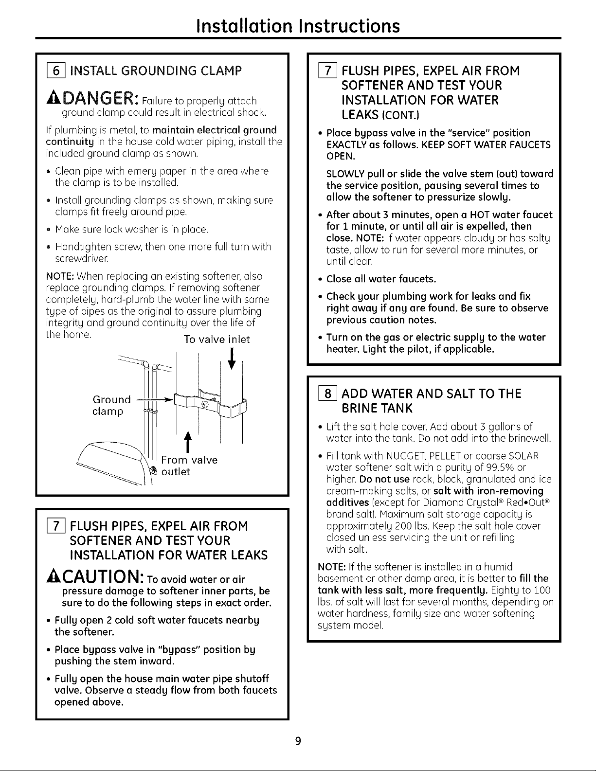
16] INSTALL GROUNDING CLAMP
-ADANGER: Failure to properly attach
ground clamp could result in electrical shock.
If plumbing is metal, to maintain electrical ground
continuity in the house cold water piping, install the
included ground clamp as shown.
• Clean pipe with emery paper in the area where
the clamp is to be installed.
Install grounding clumps us shown, making sure
clamps fit freely around pipe.
Make sure lock washer is in place.
Hundtighten screw, then one more full turn with
screwdriver.
NOTE: When replacing an existing softener, also
replace grounding clamps. If removing softener
completely, hard-plumb the water line with same
type of pipes as the original to assure plumbing
integrity and ground continuity over the life of
the home. To valve inlet
171 FLUSH PIPES, EXPEL AIR FROM
SOFTENER AND TEST YOUR
INSTALLATION FOR WATER
LEAKS ICONT.)
• Place bypass valve in the "service" position
EXACTLY as follows. KEEP SOFT WATER FAUCETS
OPEN.
SLOWLY pull or slide the valve stem tout) toward
the service position, pausing several times to
allow the softener to pressurize slowly.
After about 3 minutes, open a HOT water faucet
for 1 minute, or until all air is expelled, then
close. NOTE: If water appears cloudy or has salty
taste, allow to run for several more minutes, or
until clear.
• Close all water faucets.
Check your plumbing work for leaks and fix
right away if any are found. Be sure to observe
previous caution notes.
Turn on the gas or electric supply to the water
heater. Light the pilot, if applicable.
Ground i
clamp
i
From valve
outlet
171 FLUSH PIPES, EXPEL AIR FROM
SOFTENER AND TEST YOUR
INSTALLATION FOR WATER LEAKS
-4,CAUTION: Toavoidwateror air
pressure damage to softener inner parts, be
sure to do the following steps in exact order.
• Fully open 2 cold soft water faucets nearby
the softener.
• Place bypass valve in "bypass" position by
pushing the stem inward.
I_ ADD WATER AND SALT TO THE
BRINE TANK
• Lift the salt hole cover. Add about 3 gallons of
water into the tank. Do not add into the brinewell.
Fill tank with NUGGET, PELLET or coarse SOLAR
water softener salt with a purity of 99.5% or
higher. Do not use rock, block, granulated and ice
cream-making salts, or salt with iron-removing
additives (except for Diamond Crystal ®Red•Out ®
brand salt). Maximum salt storage capacity is
approximately 200 Ibs. Keep the salt hole cover
closed unless servicing the unit or refilling
with salt.
NOTE: If the softener is installed in a humid
basement or other damp area, it is better to fill the
tank with less salt, more frequently. Eighty to 100
Ibs. of salt will last for several months, depending on
water hardness, family size and water softening
system model.
• Fully open the house main water pipe shutoff
valve. Observe a steady flow from both faucets
opened above.
Page 10
Installation Instructions
_] CONNECT TO ELECTRICAL POWER
To gain access to the transformer/power cord
assemblg, remove the salt hole cover from the
softener. Unclip the tabs on the rear of the top cover
and rotate the cover upward to remove. DO NOT
PULL OR DISCONNECT WIRING.
• The softener works on 24 volt-60Hz electric
power. The included transformer changes
standard !20-volt AC house power to 24 volts.
Plug the transformer into a 120-volt outlet onlg.
Be sure the outlet is alwags live so it can not be
switched off bg mistake.
• Replace the top cover.
Replace the salt hole cover.
PROGRAMMING THE CONTROL
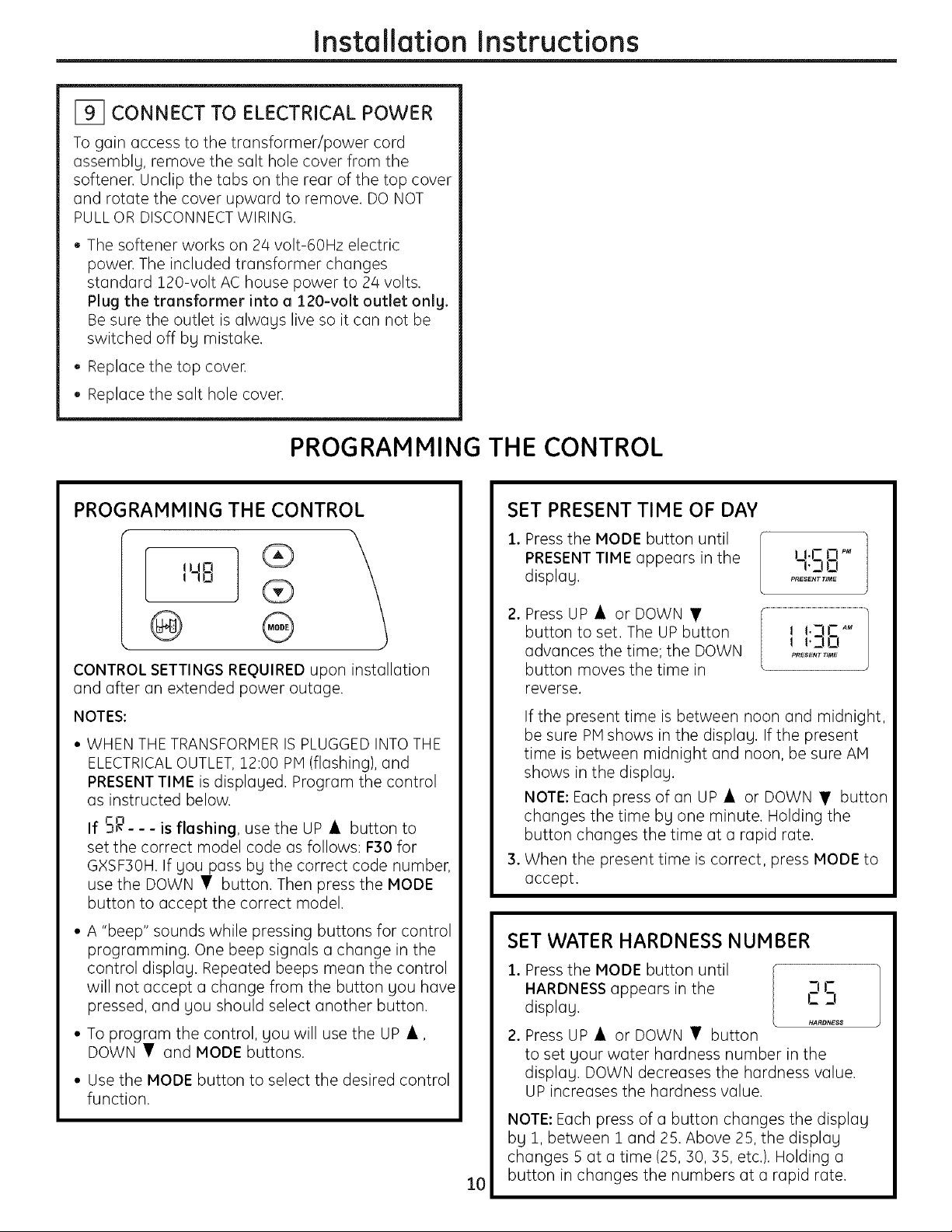
PROGRAMMING THE CONTROL
CONTROL SETTINGS REQUIRED upon installation
and after an extended power outage.
NOTES:
• WHEN THE TRANSFORMER IS PLUGGED INTO THE
ELECTRICALOUTLET, 12:00 PM (flashing), and
PRESENT TIME is displaged. Program the control
as instructed below.
If -_ - - - ,s flashing, use the UP • button to
set the correct model code as follows: F30 for
GXSF30H. If gou pass bg the correct code number,
use the DOWN • button. Then press the MODE
button to accept the correct model.
• A "beep" sounds while pressing buttons for control
programming. One beep signals a change in the
control displag. Repeated beeps mean the control
will not accept a change from the button gou have
pressed, and gou should select another button.
• To program the control, gou will use the UP •,
DOWN • and MODE buttons.
• Use the MODE button to select the desired control
function.
SET PRESENT TIME OF DAY
Press the MODE button until
,
PRESENTTIME appears in the
displag.
,
Press UP • or DOWN •
button to set. The UP button
I I 1.3C A_
advances the time; the DOWN
button moves the time in
L PRESENT TIME
reverse.
If the present time is between noon and midnight,
be sure PMshows in the displag. If the present
time is between midnight and noon, be sure AM
shows in the displag.
NOTE: Each press of an UP • or DOWN • button
changes the time bg one minute. Holding the
button changes the time at a rapid rate.
,
When the present time is correct, press MODE to
accept.
SET WATER HARDNESS NUMBER
1. Press the MODE button until
HARDNESS appears in the CIS
displag.
2. Press UP • or DOWN • button
to set gour water hardness number in the
displag. DOWN decreases the hardness value.
UP increases the hardness value.
NOTE: Each press of a button changes the displag
bg 1, between 1 and 25. Above 25, the displag
changes 5 at a time (25, 30, 35, etc.). Holding a
button in changes the numbers at a rapid rate.
10
1.1 tl
n.DO
PRESENT _ME
HARDNESS
Page 11
Installation Instructions
SET WATER HARDNESS NUMBER (CONT.)
3. When the displag shows gour water hardness
(in grains per gallon), press MODE to accept.
NOTE: If there is clear water iron in your water
supply, you will need to increase the hardness
setting bg 5 for each 1 ppm ofclearwater iron
in your water supply.
You can get the grains per gallon (gpg} hardness
of your water supply from a water analysis
laboratory. If you are on a municipal supply,
call your local water department. Or call Legend
Technical Services, an independent laboratory,
to request a water hardness test kit at
1.800.949.8220, option 4. If your report shows
hardness in parts per million (ppm) or milligrams
per liter (rag/I), simply divide by 17.1 to get the
equivalent number of grains per gallon.
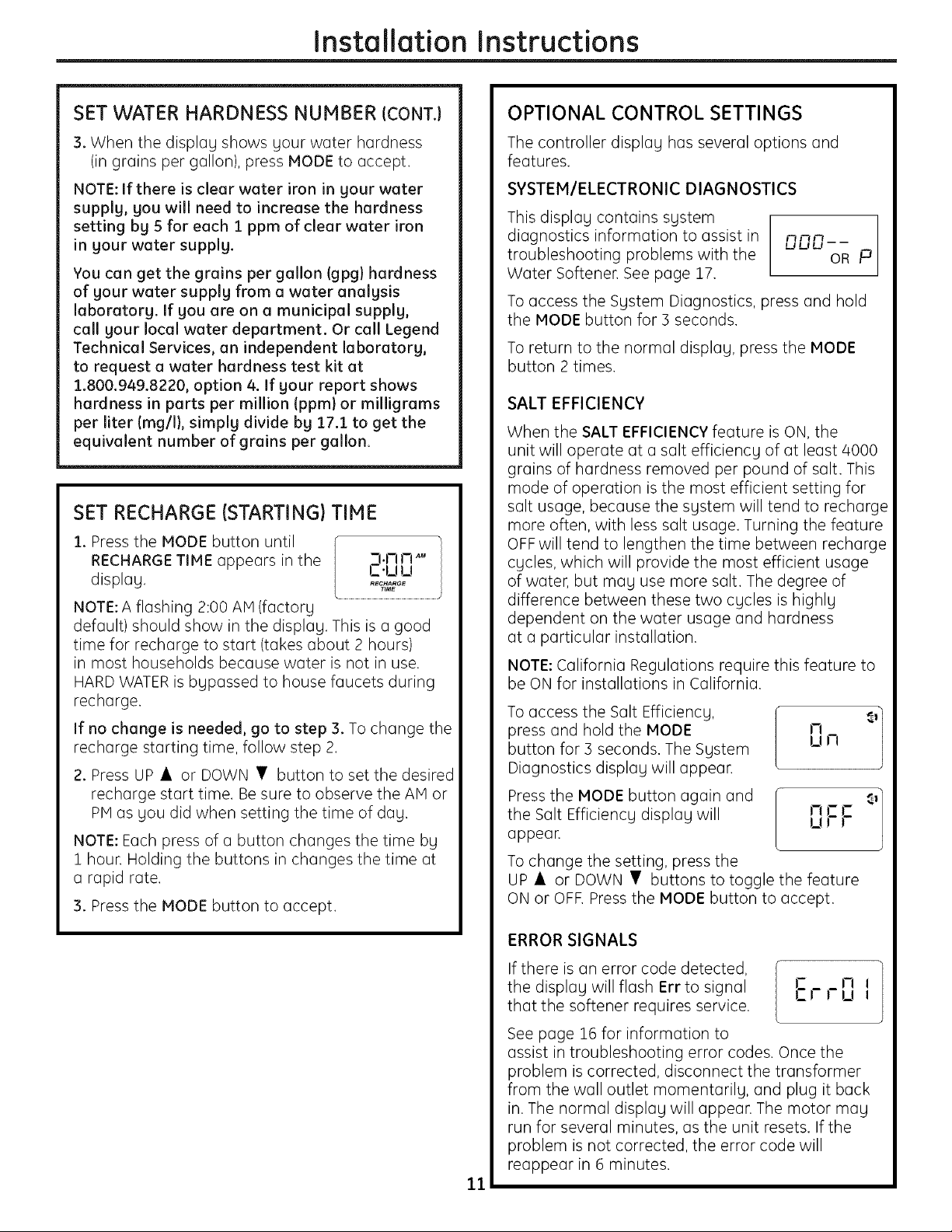
SET RECHARGE (STARTING) TIME
1.Press the MODE button until r
RECHARGE TIME appears in the / _-I.rll-I "M
d isplag, k................................._°;_i:u.............................
NOTE: A flashing 2:00 AM (factorg
default) should show in the displag. This is a good
time for recharge to start (takes about 2 hours)
in most households because water is not in use.
HARD WATER is bgpassed to house faucets during
recharge.
If no change is needed, go to step 3. To change the
recharge starting time, follow step 2.
2. Press UP • or DOWN • button to set the desired
recharge start time. Be sure to observe the AM or
PM as gou did when setting the time of dag.
NOTE: Each press of a button changes the time bg
1 hour. Holding the buttons in changes the time at
a rapid rate.
3. Press the MODE button to accept.
OPTIONAL CONTROL SETTINGS
The controller displag has several options and
features.
SYSTEM/ELECTRONIC DIAGNOSTICS
This display contains system
diagnostics information to assist in
troubleshooting problems with the
Water Softener. See page 17.
To access the Sgstem Diagnostics, press and hold
the MODE button for 3 seconds.
To return to the normal displag, press the MODE
button 2 times.
SALT EFFICIENCY
When the SALT EFFICIENCY feature is ON, the
unit will operate at a salt efficiencg of at least 4000
grains of hardness removed per pound of salt. This
mode of operation is the most efficient setting for
salt usage, because the sgstem will tend to recharge
more often, with less salt usage. Turning the feature
OFF will tend to lengthen the time between recharge
cgcles, which will provide the most efficient usage
of water, but nag use more salt. The degree of
difference between these two cgcles is highlg
dependent on the water usage and hardness
at a particular installation.
NOTE: California Regulations require this feature to
be ON for installations in California.
To access the Salt Efficiencg,
press and hold the MODE
button for 3 seconds. The Sgstem
Diagnostics displag will appear.
Press the MODE button again and
the Salt Efficiencg displag will
appear.
To change the setting, press the
UP • or DOWN • buttons to toggle the feature
ON or OFK Press the MODE button to accept.
!_1 IJ LJ --
nnn P
OR
LT,-,
NCC
urr
ERROR SIGNALS
If there is an error code detected,
the displag will flash Err to signal
that the softener requires service.
See page Z6 for information to
assist in troubleshooting error codes. Once the
problem is corrected, disconnect the transformer
from the wall outlet momentarilg, and plug it back
in. The normal displag will appear. The motor mag
run for several minutes, as the unit resets. If the
problem is not corrected, the error code will
reappear in 6 minutes.
11
Er rl] I
Page 12
SANITIZING PROCEDURES
Installation Instructions
To complete the installation, do the following
sanitizing procedures.
Care is taken at the factory to keep your water
softener clean and sanitary. Materials used to make
the softener will not infect or contaminate your water
supplg and will not cause bacteria to form or grow.
However, during shipping, storage, installation and
operation, bacteria could get into the softener. For
this reason, sanitizing as follows is suggested when
installing.
NOTE: Sanitizing is recommended bg the
Water Oualitg Association for disinfecting.
1. Be sure to complete all installation steps, including
programming the control.
2. Pour about 3/4 oz. (lY_ tablespoons) of common
5.25% unscented household bleach (Clorox, Linco,
Bo Peep, White Sail, Eagle, etc.) into the brinewell.
Refer to illustration on page 5.
3. IMPORTANT: Press and hold for 3 seconds
the faceplate RECHARGE @ button to start an
immediate recharge. RECHARGE begins to flash in
the display. The bleach will be drawn through the
water softener, and out the drain. This process
takes approximatelg 2 hours.
4. If, after sanitization, water from the house
faucet tastes salty or has a slight color, this is a
preservative from the resin tank. Turn on the cold
soft water faucets and drain for a few minutes or
until clean
NOTE: When the sanitizing recharge is over, all
remaining bleach is flushed from the conditioner
and your house COLD water supply is fully soft
immediatelg. However, your water heater is filled
with hard water and as hot water is used, it will refill
with soft water. When all the hard water is replaced
in the water heater, hot only and mixed hot and cold
water will be fullg soft. If you want totallg soft water
immediatelg, after the above recharge, drain the
water heater until the water runs cold.
ZI,WARNING:,fyoudodrainthewater
heater, use extreme care as the hot water could
cause burns. Turn the water heater off prior to
draining.
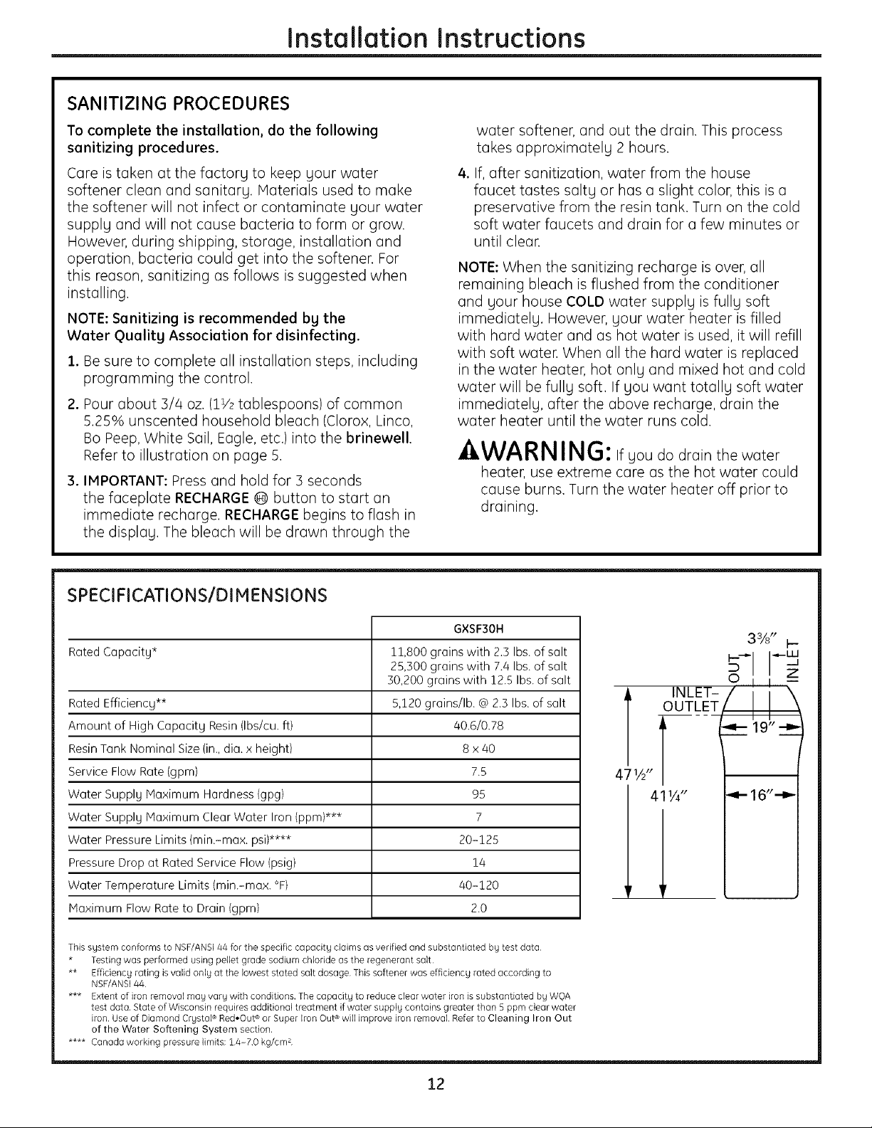
SPECIFICATIONS/DIMENSIONS
GXSF30H
Rated Capacity* 11,800 grains with 2.3 Ibs. of salt
25,300 grains with 7.4 Ibs. of salt
50,200 grains with 12.5 Ibs. of salt
Rated Efficiency** 5,120 grains/lb. @ 2.3 Ibs. of salt
Amount of High Capacity Resin (Ibs/cu. ft) 40.6/0.78
Resin Tank Nominal Size {in., dia. x height) 8 x 40
Service Flow Rate (gpm) 7.5
Water Supply Haximum Hardness (gpg) 95
Water Supply Maximum Clear Water Iron (ppm)*** 7
Water Pressure Limits (min.-max. psi)**** 20-125
Pressure Drop at Rated Service Flow (psig) 14
Water Temperature Limits (min.-max. °F) 40-120
Haximum Flow Rate to Drain (gpm) 2.0
This system conforms to NSF/ANS144 for the specific capacity claims as verified and substantiated bg test data
* Testing was performed using pellet grade sodium chloride as the regenerant salt
** Effidencg rating is valid only at the lowest stated salt dosage This softener was effidencg rated according to
NSF/ANS144
*** Extent of iron removal may vary with conditions, The capadtg to reduce clear water iron is substantiated by WOA
test data, State of Wisconsin requires additional treatment if water supply contains greater than 5 ppm clear water
iron Use of Diamond Crystal ® Red,Out ® or Super Iron Out ®will improve iron removal Refer to Cleaning Iron Out
of the Water Softening System section,
**** Canada working pressure limits: 14-70 kg/cm 2
3%" I--
i..__ i I_u..I
INLET-
OUTLET
471A"
41 I/4"
12
Page 13
About the water softener system, ge.com
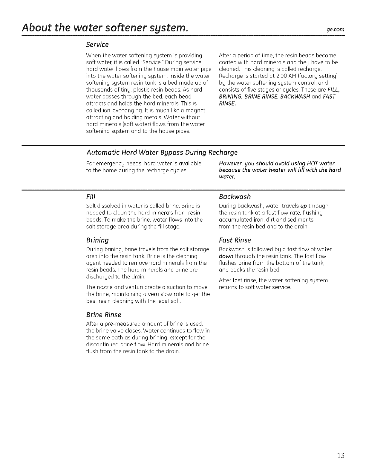
Service
When the water softening system is providing
soft water, it is called "Service." During service,
hard water flows from the house main water pipe
into the water softening system. Inside the water
softening system resin tank is a bed made up of
thousands of tiny, plastic resin beads. As hard
water passes through the bed, each bead
attracts and holds the hard minerals. This is
called ion-exchanging. It is much like a magnet
attracting and holding metals. Water without
hard minerals (soft water) flows from the water
softening system and to the house pipes.
After a period of time, the resin beads become
coated with hard minerals and theg have to be
cleaned. This cleaning is called recharge.
Recharge is started at 2:00 AH (factory setting)
by the water softening system control, and
consists of five stages or cgcles. These are FILL,
BRINING, BRINE RINSE, BACKWASH and FAST
RINSE.
Automatic Hard Water Bgpass During Recharge
For emergencg needs, hard water is available
to the home during the recharge cgcles.
Fill
Salt dissolved in water is called brine. Brine is
needed to clean the hard minerals from resin
beads. To make the brine, water flows into the
salt storage area during the fill stage.
However, gou should avoid using HOT water
because the water heater will fill with the hard
water.
Backwash
During backwash, water travels up through
the resin tank at a fast flow rate, flushing
accumulated iron, dirt and sediments
from the resin bed and to the drain.
Brining
During brining, brine travels from the salt storage
area into the resin tank. Brine is the cleaning
agent needed to remove hard minerals from the
resin beads. The hard minerals and brine are
discharged to the drain.
The nozzle and venturi create a suction to move
the brine, maintaining a very slow rate to get the
best resin cleaning with the least salt.
Brine Rinse
After a pre-measured amount of brine is used,
the brine valve closes. Water continues to flow in
the same path as during brining, except for the
discontinued brine flow. Hard minerals and brine
flush from the resin tank to the drain.
Fast Rinse
Backwash isfollowed by a fast flow of water
dawn through the resin tank. The fast flow
flushes brine from the bottom of the tank,
and packs the resin bed.
After fast rinse, the water softening system
returns to soft water service.
15
Page 14
About the water softener sgstem.
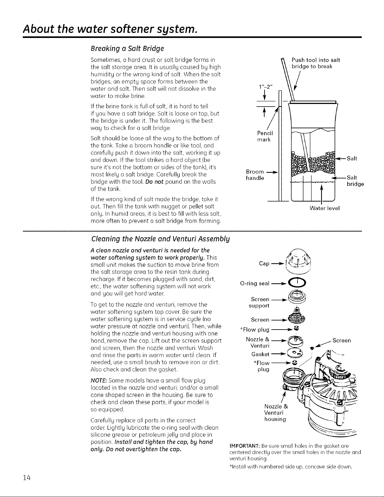
Breaking a Salt Bridge
Sometimes, a hard crust or salt bridge forms in
the salt storage area. It is usuallu caused bu high
humidity or the wrong kind of salt. When the salt
bridges, an empt Uspace forms between the
water and salt. Then salt will not dissolve in the
water to make brine.
If the brine tank is full of salt, it is hard to tell
if Uou have a salt bridge. Salt is loose on top, but
the bridge is under it. The following isthe best
wag to check for a salt bridge.
Salt should be loose all the wag to the bottom of
the tank. Takea broom handle or like tool, and
carefullu push it down into the salt, working it up
and down. If the tool strikes a hard object (be
sure it's not the bottom or sides of the tank), it's
most likelu a salt bridge. Carefullu break the
bridge with the tool. Do not pound on the walls
of the tank.
If the wrong kind of salt made the bridge, take it
out. Then fill the tank with nugget or pellet salt
only. In humid areas, itis best to fill with less salt,
more often to prevent a salt bridge from forming.
Push tool into salt
bridge to break
/
Pencil
mark
Broom
handle
bridge
Water level
14
Cleaning the Nozzle and Venturi Assemblg
A clean nozzle and venturi is needed for the
water softening system to work properly. This
small unit makes the suction to move brine from
the salt storage area to the resin tank during
recharge. If it becomes plugged with sand, dirt,
etc., the water softening sustem will not work
and Uouwill get hard water.
To get to the nozzle and venturi, remove the
water softening sustem top cover. Be sure the
water softening sustem is in service cgcle (no
water pressure at nozzle and venturi). Then, while
holding the nozzle and venturi housing with one
hand, remove the cap. Lift out the screen support
and screen, then the nozzle and venturi. Wash
and rinse the parts in warm water until clean. If
needed, use a small brush to remove iron or dirt.
Also check and clean the gasket.
NOTE;Some models have a small flow plug
located in the nozzle and venturi, and/or a small
cone shaped screen in the housing. Be sure to
check and clean these parts, if uour model is
so equipped.
Carefullu replace all parts in the correct
ordeE Lightlu lubricate the o-ring seal with clean
silicone grease or petroleum jellu and place in
position. Install and tighten the cap, by hand
only. Do not overtighten the cap.
Cap -_
O-ring seal _0
Screen --_._ @
support
Screen
*Flow plug _
Nozzle & __ _ Screen
Venturi _ _--
Gasket _v=_
plug
*Flow -_l__
Nozzle &
Venturi
housing
IMPORTANT: Be sure smoll holes in the gasket are
centered directlg over the small holes in the nozzle and
venturi housing.
*Install with numbered side up, concove side down.
i
Page 15
Normal Operation, Control Displays
During normal operation, the present time of day
and AM or PM show in the control display area.
When the demand computer determines a
recharge is needed, RECHARGE TONIGHT begins
to flash in the display along with the present
time. RECHARGE TONIGHT flashes until the next
recharge start time, then changes to RECHARGE,
which flashes until the recharge is over.
Feature: Optional Recharge Controls
Sometimes, a manually started recharge may
be desired or needed. Two examples:
::Ji::You have used more water than usual (house
guests, extra washing, etc.) and you mag run
out of soft water before the next recharge.
!i::iThe sgstem ran out of salt.
Use one of the following features to start a
recharge immediately, or at the next preset
recharge start time.
ge.com
RECHARGE TONIGHT
Touch (do not hold) the RECHARGE 0 button.
RECHARGE TONIGHT flashes in the control
display area. A recharge will occur at the next
preset recharge start time. If you decide to cancel
this recharge, touch the same button once more.
RECHARGE NOW
Press and hold the RECHARGE _ button until
RECHARGE NOW starts to flash in the control
display area. The water softening system begins
an immediate recharge and, when over in about
two hours, you will have a new supply of soft
water Once started, you cannot cancel this
recharge.
Feature: Memory
If electrical power to the water softening system
is interrupted, the control display is blank, and
the blue indicator light is off, but the control
keeps correct time for about 6 hours. When
power is restored, you have to reset the present
time only if the display and blue indicator light
are flashing. All other settings are maintained
and never require resetting unless a change is
desired.
If the time isflashing after a long power outage,
the water softening sgstem continues to work as
it should to provide you with soft water. However,
recharge may occur at the wrong time of day
until you reset the control to the correct time
of day.
Feature/Service: Automatic Electronic Diagnostics
The control computer has a self-diagnostic
function for the electrical system (except input
power and water meter). The computer monitors
the electronic components and circuits for
correct operation. If a malfunction occurs,
an error code appears in the control display.
The chart on Error Codes shows the error
codes that could appear and possible reasons
for each code. See Monuollbl Initiated Electronics
Diognostics to further isolate the defect.
15
Page 16
About the water softener system.
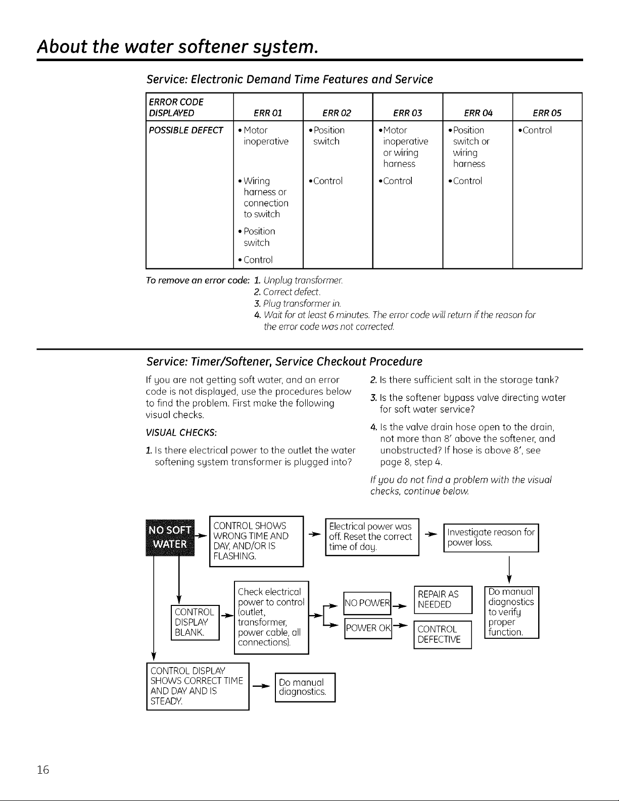
Service: Electronic Demand Time Features and Service
ERRORCODE
DISPLAYED ERR03 ERR04 ERR05
POSSIBLEDEFECT • Control
Toremove an error code: 1. Unplugtransformer.
ERR01
• Motor
inoperative
• Wiring
harness or
connection
to switch
• Position
switch
• Control
Z Correctdefect.
& Plug transformer in.
4. Wait for ot leost 5 minutes. The error code will return if the reasonfor
theerror code was not corrected.
ERR02
•Position
switch
•Control
•Motor
inoperative
or wiring
harness
•Control
•Position
switch or
wiring
harness
• Control
Service: Timer/Softener, Service Checkout Procedure
If gou are not getting soft water, and an error
code is not displaced, usethe procedures below
to find the problem. First make the following
visual checks.
VISUAL CHECKS:
1.Is there electrical power to the outlet the water
softening sgstem transformer is plugged into?
CONTROL SHOWS
WRONG TIME AND
DAY,AND/OR IS
FLASHING.
Electricalpower was I Investigate reason for
off. Resetthe correct _ Ipower oss.
time of dag.
Checkelectrical
power to control
CONTROL
DISPLAY
BLANK.
transformer,
.._ (outlet,
power cable,all
connections).
"-_"C POWEROK--_- I CONTROL
Z Isthere sufficient salt in the storage tank?
3. Isthe softener bypass valve directing water
for soft water service?
4. Is the valve drain hose open to the drain,
not more than 8' above the softener, and
unobstructed? If hose is above 8', see
page 8, step 4.
tf bloudo not find a problem with the visual
checks, continue below.
INO POWERI.__. REPAIRAS
NEEDED
DEFECTIVE
diagnostics
Domanual
to verifg
function.
i proper
16
CONTROL DISPLAY
SHOWS CORRECTTIME
AND DAYAND IS
STEADY.
Domanual
diagnostics.
Page 17
Service: Manually Initiated Electronics Diagnostics
ge.com
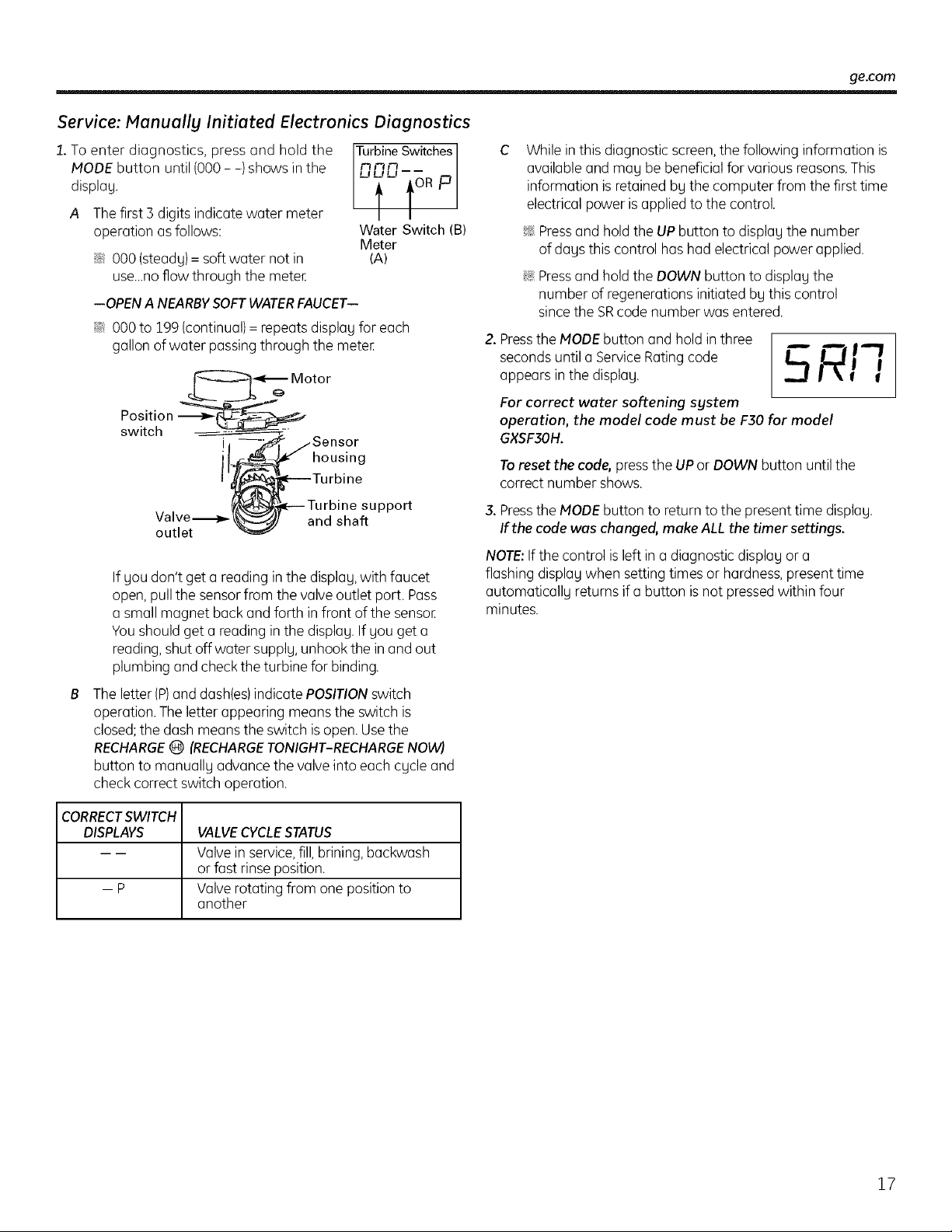
1.To enter diagnostics, press and hold the
MODE button until (000 - -) shows in the
Turbine Szjtches 1
displag.
A The first ] digits indicate water meter
operation asfollows:
Water Switch (B)
Meter
::J_::000 (steady)= soft water not in
use_.noflow through the meter.
--OPEN A NEARBY SOFT WATER FAUCET--
::J_::000 to 199 (continual)=repeats display for each
gallon of water passing through the meter.
switch
Valve-_-
outlet
..Sensor
housing
and shaft
If you don't get a reading in the display, with faucet
open, pullthe sensorfrom the valve outlet port. Pass
a small magnet back and forth in front of the sensor.
Youshould get a reading in the display. If you get a
reading,shut off water supply,unhook the in and out
plumbing and check the turbine for binding.
The letter (P)and dash(es)indicate POSITIONswitch
operation. Theletter appearing means the switch is
closed;the dash means the switch isopen.Usethe
RECHARGE0 (RECHARGETONIGHT-RECHARGENOW)
button to manually advance the valve into each cycle and
check correct switch operation.
(A)
pport
While in this diagnostic screen,the following information is
available and may be beneficial for various reasons.This
information is retained by the computer from the first time
electrical power isapplied to the control.
?_:Pressand hold the UP button to display the number
of days this control hashad electrical power applied.
?_:Pressand hold the DOWN button to display the
number of regenerations initiatedby this control
sincethe SRcode number was entered.
2. Press the MODE button and hold in three
seconds until a Service Rating code
appears in the displag,
For correct water softening system
operation, the model code must be F30 for model
GXSF3OH,
To reset the code, press the UP or DOWN button until the
correct number shows.
3, Press the MODE button to return to the present time displag,
If the code was changed, make ALL the timer settings.
NOTE: If the control is left in a diagnostic display or a
flashing display when setting times or hardness, present time
automatically returns if a button is not pressed within four
minutes.
5 i'--EI-"/
I I
CORRECTSWITCH
DISPLAYS
-p
VALVECYCLESTATUS
Valvein service,fill,brining,backwash
or fast rinse position.
Valverotating from one position to
another
!7
Page 18
About the water softener system.
Service: Manuallg Advance Recharge Check
NOTE:The control display must show a steady
time (not flashing).
1. Pressthe RECHARGE@ button and hold in for
three seconds. RECHARGENOW begins to 3.
flash as the water softening system enters the
fill cycle of recharge. Remove the brinewell
cover and, using a flashlight, observe fill water
entering the brine tank. If water does not enter
the tank, look for an obstructed nozzle, venturi, 4.
fill flow plug or brine tubing. See Coreand
Cleaning of the Water Softener System section.
2. After observing fill, press the RECHARGE@
button to move the water softening system
into brining. A slow flow of water to the drain
will begin. Verify brine draw from the brine
tank by shining a flashlight into the brinewell
and observing a noticeable drop in the liquid
level over an extended period of time.
NOTE:Be sure a salt bridge is not preventing
water from contacting salt. SeeCore and
cleoning of the water softening system section.
If the water softening system does not draw
brine, check:
::Ji::nozzle and/or venturi dirty or defective.
::J_::defective nozzle and venturi seal.
::Ji::nozzle and venturi not seated properly
on gasket.
::Ji::other inner valve defect {rotor seal, rotor and
disc, wave washer, etc.).
?_:restricted drain {check drain fitting and
hose).
NOTE:If water sgstem pressure is low, an
elevated drain hose mag cause back pressure,
stopping brine draw.
Again, press the RECHARGE0 button to move
the water softening sgstem into backwash.
Look for a fast flow of water from the drain
hose. A slow flow indicates a plugged top
distributor, backwash flow plug or drain hose.
Press the RECHARGE0 button to move the
water softening sgstem into fast rinse. Again
look for a fast drain flow. Allow the water
softening sgstem to rinse for a few minutes
to flush out ang brine that mag remain in
the resin tank from the brining cgcle test.
5.
To return the water softening sgstem to
service, press the RECHARGE_ button.
18
Page 19

Care and cleaning of the water softening system, geeom
Checking the Salt Storage Level and Refilling
Brine (salt dissolved inwater)is needed for each
and every recharge. The water for making brine
is metered into the salt storage area by the
water softening system valve and control.
However, gou must keep the tank supplied
with salt.
When to refill with salt: Check the salt level a
few weeks after you install the water softening
system and periodically after that. Refill when
the tank gets lessthan !/3 full. In humid areas it
is best to refill with less salt and more often, to
avoid forming a salt bridge (see page 14).Never
allow the softening system to use all the salt
before you refill it. Without salt, you will soon
have hard water.
Cleaning Iron Out of the Water Softening Sgstem
Use clean water softening salts only, at least
99.5% pure. NUGGET,PELLETor coarse SOLAR
salts are recommended. Do not use rock, block,
granulated or ice cream making salts. They
contain dirt and sediments, or mush and cake,
and will create maintenance problems.
CAUTION: Wotersoftening salt
with iron removing additives: Some salts
may have an additive to help the water
softening system handle iron in the water
supply. Although this additive may help to
keep the water softening system resin clean,
it may also release corrosive fumes that
weaken and shorten the life of some water
softening system parts. GE recommends
using only Diamond Crystal®Red,Out®
brand salt.
Your water softening system takes hardness
minerals (calcium and magnesium) out of
the water. Also, it can control some (see the
Specification Guidelines section) "clear water"
iron. With clear water iron, water from a faucet
is clear when first put into a glass. After 15 to 30
minutes, the water begins to cloud or turn rust
colored. A water softening system will not
remove any iron that makes the water cloudy
or rusty as it comes from the faucet (called red
water iron).To take red water iron out of water,
or over the maximum of clear water iron,
an iron filter or other equipment is needed.
GErecommends using only Diamond Crystal®
Red.Out ®brand salts with Iron Fighter®additive
to help keep the resin bed clean of clear iron. If
your water supply has clear water iron, periodic
resin bed cleaning is needed. GErecommends
using Super Iron Out®brand resin bed cleaner
to thoroughly clean your resin bed if your iron
content is high. Clean the bed at least every six
months, or more often if iron appears in the soft
water between cleanings.
IMPORTANT:It isimportant to mix the resin bed
cleaner with water (following the manufacturer's
instructions), pour it into the brinewell tube
(seepage 5) and recharge the softener
immediately. Do not pour the resin bed cleaner
in with the salt, as it will not be as effective in
cleaning the resin, and can cause damage to
the softener if it is left in the brine tank for an
extended period due to the corrosive gases
that are formed.
19
Page 20

Before you call for service...
Save time and moneg! Review the chart on the following
pages first and gou mag not need to call for service.
Troubleshooting Tips
NO SOFTWATER- Most Common Problems:
Check the following before coiling for service:
• Not enough saltishould be at least 1/3 full.
• Bypass valve in "Bypass" positioniknob should be in the "OUT" (service)position.
• Hardness setting too low. Check hardness setting and adjust. Verify hardness of supply
water--from local water company, water test or call the GEAnswer Center.
• Salt Bridgeisalt solidifies above water level so that brine water is not in contact with
salt. See the Breaking a Salt Bridge section.
Problem Possible Causes What To Do
No soft water Faucet or fixture where sample was •
taken not plumbed to soft water.
NOTE:Be sure sample is from a faucet
that does not mix soft and hard waten
For example, o single lever kitchen faucet,
if the cold side is plumbed to hard woten
Nosalt inthe brine tank or
salt bridged
Transformer unplugged at wall outlet or
power cableto softener not connected.
Fuseblown or circuit breaker popped
on circuit to electrical outlet.
Electrical outlet on a circuit that can
continuously be switched off
Manual bypass valve in bypass position • Be surethe bypass valve stem ispositionedproperly, with the
Valve drain hose pinched, plugged,
elevated too high or otherwise
restricted
Toconservesalt,the installermay haveisolatedsomefixtures
(outsidefaucets, toilets,etc.)from softwater.Fromthe outlet
of the water softening system, trace the water flow path,
in house plumbing. If soft water isnot directed to a faucet
or fixture where wanted,consult a plumber
Checkfor a salt bridge or,ifthe tank isempty, refill with
recommended salt. Press(for3 seconds)the RECHARGE@
button to start an immediate recharge and restore
soft water supply.
Checkfor a lossof electrical power to the water softening
system, due to any of these conditions and correct as needed.
With the power supply restored, observethe faceplate time
display and read Programming the Controlsection.
NOTE:Theelectricaloutlet forthe softenershouldbe
liveso it cannot be accidentally switched off
knob in the OUTposition.Observeinstructions on the decal
at the end of the stem.
• Any restriction inthis drain hosemay preventproper
operationof the nozzle andventuri and reduce or prevent
brine draw during recharge.
20
Nozzleand venturi dirty, incorrectly
assembled or damaged
Referto Cleaningthe Nozzle and VenturiAssemblg instructions.
With water pressureto the water softening system off,take the
nozzleassembly apart. Inspect, clean and replace asneeded.
Any foreign particle(s),scratches, nicks,etc.,in the passagescan
preventoperation.Besureholesin thegasket are centeredover
holesinthe housing.
Page 21

Problem Possible Causes What To Do
Water hard sometimes Using hot water while the water , Avoid usinghot water during water softening sgstem
softening sgstem is regenerating recharge because the water heater will refill with hard wateE
SeeAutomatic Hard Water BypassDuringRechargesection,
page !3.
Control HARDNESSnumber setting oPressthe MODEbutton until arrow pointsto HARDNESS.
too low Be surethe number shown isthe same asthe actual grains per
gallon hardness of your water supplg Seethe Programming
the Control section ifa change in the setting is needed.
Grains of hardness in gout water o Water hardnesscan change over time, especiallg in wellwateE
supplg have increased To check, havethe water tested bg a water analgsis laboratorg
or call gour localwater department. Adjust the HARDNESS
number setting as needed.
Water feels slippery Absenceof hardness minerals , This is normal. Hardnessin water gives it the abrasive feel
after installation of gou mag have been accustomed to. The slipperg feelisthe
water softening system clean feelof soft wateE
Water softening system Water softening sgstem isa , Does not use much salt to regenerate-verg efficient.
not using any salt "demand" unit
Possible salt bridge , Seethe About the Water SoftenerSgstem section,page 14.
ge.eom
Possible plugged nozzle and venturi _ Seethe About the Water SoftenerSystem section,page 14.
Water is blue color Acidic water in copper plumbing o Have the water tested at once.
after water softening
system was installed
Water softening system Meter turbine stuck , Seethe Service:Manually Initiated ElectronicsDiagnostics
not regenerating section for troubleshooting procedures,page 17.
, Callfor service.
Sensorwire not plugged into , Seethe Service:Manually Initiated ElectronicsDiagnostics
the control section for troubleshooting procedures,page 17.
, Callfor service.
No power to unit , Checkthe circuit breakeror fuses.
Mechanical defect , Callfor service.
Cloudiness on glassware Combination of soft water and , This is called etching and is permanent. To prevent this
(automatic dishwashers) too much detergent from happening, uselessdetergent if gou havesoft wateE
Wash glassware in the shortest cgcle that will get them clean.
Excessive/high level Valve drain hose pinched, , Ang restriction in this drain hosemag prevent proper
of water in brine tank plugged, elevated too high operation of the nozzleand venturi and reduceor prevent
or otherwise restricted brine draw during recharge.
Nozzleand ventud dirtg, incorrectlg
assembled or damaged
See the Cleaning the Nozzle and Venturi Assembly section,
page !4. With water pressure to the water softening sgstem
off, take the nozzle assemblg apart. Inspect, clean and
replace as needed. Ang foreign particle(s), scratches, nicks,
etc., in the passages can prevent operation. Be sure holes
in the gasket are centered over holes in the housing.
21
Page 22

Before you call for service...
Troubleshooting Tips
Problem Possible Causes What To Do
Salty tasting or Unit not sanitized * Complete theSanitization Procedureson page 12.
brown/yellow colored • At completion of recharge cucle (approx.2 hrs),run water
water after installation from faucets to purge the salty water.
Lowwater pressure Checkpressure.
• Drain height 8' or less,pressureshouldbe minimum of 20 psi.
• Drain height above8', pressureshouldbe minimum of 50 psi.
Restricted drain hose • Clean and reconnect hose.
• Check for kinksin drain line.
Brown/yellow Unit was idle for a period of time • Complete the Sonitizotion Procedureson page 12.
colored water
Resinbeads showing Cracked distributor • Callfor service,
up in drinking water
and sink
Soundsgou might hear Running water from the unit • Thisisnormal.
into a drain during recharge
Water has air bubbles Air in sgstem after installation • Will go away after it runs for a while.
and is cloudy
Error Code on control Wiring mag have worked loose • Seepage 16for details.
in the control
• Unplug transformer,
• Removecontrol cover,releaseclips on side.
• Checkfor loose/incorrect wiring connections to electronic
board or switch. Reconnect asrequired.
• Reassemblecontrol cover.
• Plugin Transformer,
• Wait six minutes for Error Codeto reappear,
• If ErrorCodereappears,call for service.
22
Page 23

Parts list. g_._om
11
4
\
28
16
55 / 55
3_
\
12
13
22
ggg
2g
/
24
36
33 32
_- 3O
$ 31
23
Page 24

Parts list.
_135
,_¢-25
124-- 115
,/
134 133
-- 130
132
145
J
146 147
24
117
118
119
120
121
150
S
Page 25

Parts catalog, go. o
GENERAL ELECTRIC PARTS CATALOG
G
X
S
F
3
0
H
REF. NO. PART NO. PART DESCRIPTION (02)
0003 WS35XlO001 O-RING SEAL KIT 1
0004 WS34XlO015 DECAL, FACEPLATE 1
0005 WSO7XlO004 HOSE, DRAIN, 20 FT. i
0007 WS14XlO002 DISTRIBUTOR, TOP i
0008 WS14XlO001 DISTRIBUTOR, BOTTOM i
0009 WSO1XIO002 RESIN, i CU. FT. i
0010 WS32XlO011 RESIN TANK, 9 X 40 i
0011 WS31XlO022 COVER, TOP W/LENS i
0012 WS31XlO023 FACEPLATE 1
0013 WS21XlO017 CONTROL 1
0016 WS26XlO013 TRANSFORMER WITH
POWER CORD i
0017 WS31XlO021 COVER, SALT HOLE,
WITH LABELS 1
0018 WS33XlO001 VAPOR BARRIER i
0019 WS33XIO007 RIM 1
0020 WS31XlO024 COVER, BRINEWELL W/DECAL 1
0021 WSO2XlO009 NUT 1
0022 WS32XlO017 BRINEWELL W/DECAL 1
0023 WSO2XlO027 SCREW 1
0024 WS32XlO016 TANK, BRINE, ROUND 1
0025 WS18XIO003 CLAMP, HOSE 2
0026 WS22XlO016 ADAPTER, HOSE 1
0027 WS22XlO017 GROMMET 1
0028 WS35XlO035 GROUND CLAMP KIT 1
0029 WS15XlO035 BRINE VALVE ASM. 1
0030 WS35XlO036 FLOAT, STEM & GUIDE 1
0031 WSO3XIO006 CLIP 1
0032 WS15XIO006 VALVE BODY, BRINE 1
0033 WSO3XIO007 CLIP 1
0034 WSO3XIO008 SCREEN 1
0035 WSO7XIO002 TUBING ASM. 1
0036 WSO7XIO015 BRINE TUBE ASM. 1
0037 WS31XIO018 BACK COVER, ELECTRONICS 1
0038 WSO2XlO029 SPACER 1
0039 WSO2XIO030 FACEPLATE SUPPORT 1
0055 WS28XlO003 RETAINER CLAMP 2
0056 WS28XlO004 CLAMP 2
0101 WSO2XIO012 SCREW 1
0102 WSO2XIO013 SPACER 1
0103 WS21XIO003 SWITCH 1
0104 WSO3XIO009 PIN, EXPANSION 1
0105 WSO2XIO014 SCREW 5
0106 WS31X10006 COVER, VALVE 1
0107 WS03X10010 WAVE SPRING 1
0108 WS26X10002 ROTOR & DISC ASM. 1
0109 WS19X10004 CAP, VENTURI 1
0110 WS03X10011 SEAL, O-RING 1
NOTE: Codes in the State ofMassachusetts require installation bg a licensed
plumber and do not permit the use of the saddle valve. For installation, use
plumbing code 248-CMR of the Commonwealth of Massachusetts.
25
Page 26

Parts catalog.
GENERAL ELECTRIC PARTS CATALOG
REF. NO. PART NO. PART DESCRIPTION (02)
0111 WSI9XIO005 SUPPORT SCREEN 1
0112 WSO3XIO013 SCREEN 1
0113 WS22X10020 FLOW PLUG, .10 GPM 1
0114 WS08X10005 GASKET & ASPIRATOR 1
0115 WSO3X10015 CONE SCREEN 1
0116 WS22X10021 PLUG, FILL FLOW, .30 GPM 1
0117 WS03XI0017 FERRULE NUT 1
0118 WS15X10034 NOZZLE/VENTU RI BODY 1
0119 WSO3X10018 RETAINER 1
0120 WSO3XlO019 SEAL, O-RING, 1/4" X 3/8" 2
0121 WSI5XIO010 BODY, VALVE 1
0122 WS03X10020 SPRING 1
0123 WS22X10022 PLUG, DRAIN SEAL 1
0124 WS15X10009 NOZZLE/VENTU RI ASM. 1
0130 WS35X10005 SEAL KIT,3/4" 1
0132 WS22X10023 ADAPTER, DRAIN HOSE 1
0133 WS03X10021 O-RING, 5/8"X 13/16" 1
0134 WS03X10022 PLUG, FLOW, RINSE CONTROL 1
0135 WS03X10023 CLIP 1
0136 WS26X10003 CAM & GEAR 1
0137 WS26X10004 BEARING 1
0138 WS26X10005 PLATE, MOTOR, 3/4" 1
0139 WS02X10015 SCREW, #6-20 X 3/8" 2
0140 WS26X10011 MOTOR ASM. 1
0141 WS02X10016 SCREW, #6-20 X 7/8" 2
0143 WS60X10013 ADAPTER-NPT THREADED-STD VALVE 2
0145 WS60X10004 CLIP 4
0146 WS28X10017 HARNESS WIRE, SENSOR ASS?'.,3/4" 1
0147 WS19X10006 TURBINE & SUPPORT ASM, 1
0150 WS03X10024 SEAL, O-RING 4
0151 WS15X10053 BYPASS VALVE ASM, 1
0152 WS03X10025 SEAL, O-RING 4
0999 49-50177 OWNER'S MANUAL 1
G
X
S
F
3
0
H
WS60X10014 INSTALLATION KIT 1
26
NOTE: Codes in the State of Massachusetts require installation by a licensed
plumber and do not permit the use of the saddle valve. For installation, use
plumbing code 248-CMR of the Commonwealth of Massachusetts.
Page 27

GEWater Softening System Warranty. (For Customers in the United States)
All warrants service provided by our 5martWater T"Authorized Servicer
Network. To schedule service, call 800.952.5039 M.&) or 866.777.7627
(Canada). Please hove serial number and model number available when
calling for service.
Staple your receipt here.
Proof o1:the original purchase
dote is needed to obtain service
under the warranty.
For The Period Of: We Will Replace:
OneYear Any part of the Water Softening Sustemwhich fails due to a defect in materials or workmanship.
From thedate of the During this limited one-year warranty, GEwill also provide,free of charge, all labor and related
original purchase serviceto replacethe defective par[.
ThreeYears Theelectronic monitor, if it fails due to a defect in materials or workmanship. Duringthis
From thedate of the three-year limited warranty, Sou will be responsiblefor ang labor or related service costs.
original purchase
TenYears A replacement brine tank or cabinet, if eitherfails due to a defect in materials or workmanship.
From thedate of the During this ten-year limited warranty, Souwill be responsiblefor ang labor or relatedservicecosts.
original purchase
What Is Not Covered:
[] Service trips to sour home to teach Sou how to use
the product.
[] Improper installation, delivers or maintenance.
[] Failure of the product if it is abused, misused, altered, used
commercially or used for other than the intended purpose.
[] Use of this product where water is microbiologically unsafe
or of unknown quality, without adequate disinfection before
or after the system. Systems certified for cyst reduction may
be used on disinfected water that may contain filterable
cysts.
[] Replacement of house fuses or resetting of circuit breakers.
[] Damage to the product caused bg accident, fire, floods or
acts of God.
[] Incidental or consequentialdamage causedbg possible
defects with this appliance, its installation or repair.
[] Product not accessible to provide required service.
Limited Warranty. Any implied warranties, including the implied warranties of merchantability or fitness for
I EXCLUSION OF IMPLIED WARRANTIES--Your sole and exclusive remedy is product repair as provided in this I
a particular purpose, are limited to one gear or the shortest period allowed by law.
This warranty is extended to the original purchaser and an;] succeeding owner for products purchased for home use within
the USA. If the product is located in on area where service bbla GEAuthorized Servicer is not available, Sou may be
responsible for a trip charge or blOUma_j be required to bring the product to an Authorized GEService location for service.
InAlaska, the warranty excludes the cost of shipping or service ca!ls to your home.
Some states do not allow the exclusion or limitation of incidental or consequential damages. This warrants gives you
specific legal rights, and you mog also have other rights which vary from state to state. To know what your legal
rights are, consult your local or state consumer affairs office or your state's AttorneLj General.
Warrantor: General Electric Company. Louisville, KY40225
I
I
27
Page 28

GEWater Softening System Warranty. (For Customers in Canada)
All warranty service provided by our Factory Service Centers or an authorized technician. For service,
call toll free 1.866. 777.7627. Please hove serial number and model number available when coiling for service.
For The Period Of: We Will Replace:
One Year Any part ofthe Water Softening System which fails due to a defect in materials or workmanship.
From the date ofthe During this limited one-year warranty, GEwill also provide,free of charge, all labor and related
on_ginalpurchase service to replace the defective part.
ThreeYears Theelectronicmonitor, ifit fails due to a defect in materials or workmanship. During this
From the date ofthe three-year limited warranty, you will beresponsible for any labor or related service costs.
anginal purchase
TenYears Areplacement brine tank or cabinet, if either fails due to a defect in materials or workmanship.
From the date ofthe During this ten-year limited warranty, you will be responsiblefor any labor or related servicecosts.
anginal purchase
What Is Not Covered:
• Service tripsto your home to teach you how to use
the product.
• Improper installation, delivery or maintenance.
• Failure of the product if it is abused, misused, altered, used
commercially or used for other than the intended purpose.
• Useof this product where water is microbiologicallg unsafe
or of unknown quality, without adequate disinfection before
or after the system. Systemscertified for cyst reduction may
be used on disinfected water that may contain filterable
cysts.
EXCLUSION OF IMPLIED WARRANTIES--Your sole and exclusive remedy is product repair as provided in this
Limited Warranty. Any implied warranties, including the implied warranties of merchantability or fitness for
a particular purpose, are limited to one year or the shortest period allowed by law.
This warranty isextended to the original purchaser and any succeeding owner for products purchased for home use within
Canada. In-home warranty service will be prodded in areas where it is available and deemed reasonable by Mabe to provide.
WARRANTOR IS NOT RESPONSIBLE FOR CONSEQUENTIAL DAMAGES. ]
• Replacement of house fuses or resetting of circuit breakers.
• Damage to the product caused by accident, fire, floods or
acts of God.
• Incidental orconsequential damage caused by possible
defects with this appliance, its installation or repair.
• Product not accessible to provide required service.
II
28
I Warrantor: MABE CANADA INC. I
Page 29

Informaci6n de seguridad .... so
Instrucciones
de instalaci6n .............. ] t-4o
Instrucciones paso por paso .... 34-40
Instrucciones de operaci6n
C6mo limpiar la ensambladura
de la boquilla g el Venturi .......... 43
C6mo romper un puente de sal ..... 42
Funciones ........................ 44
Servicio ................... 41, 44-47
Sistema de descalcificaci6n
de agua ...................... 41-47
Cuidado g limpieza ............ 48
Consejos para la soluci6n
de avenas .................. 49-5!
Soporte al diente
Garant[a ......................... 58
Lista de partesicat61ogo ....... 54-57
Soporte al consumidor ............ 59
Escriba aqui los n_meros de modelo
y de la serie:
Modelo No.
Serie No.
Para encontrar estos nOmeros,
levante la cubierta g mire en el borde,
debajo del panel del control.
29
Page 30

INFORMACION INIPORTANTE DE SEGURIDAD.
LEA TODAS LAS INSTRUCCIONES ANTES DEL USO.
ADVERTENCIA
Par su seguridad, se debe seguir la informaci6n en este manual con el fin de reducir el riesgo de
una descarga eldctrica, dahos a la propiedad o dahos personales.
PRECAUCIONESDE SEGURIDAD
?_:Revisey cumpla con todos losc6digos estatales y
locales.Observelas pautas aqui presentadas.
::Ji::Tengacuidado al manipular el sistema de
descalcificaci6n de agua. NoIo voltee,deje caer,
arrastre o coloque en protuberancias extremas.
::Ji::Lossistemas de descalcificaci6n de agua que utilicen
cloruro de sodio (sadpara la recarga agregan sodio al
agua. Lospersonasque siguendietos conrestricciones
de sodiodeben considerar d sodio odicionalcoma
porte de su consumogeneral.Eldoruro depotosio
puede servir coma uno oltemotivo poro el cloruro de
sodiode su descolcificodor.
Elsistemade descalcificaci6nde agua funciona
solamente con 28voltios-60 Hz.Cerci6resede usar
exclusivomenteel tronsformodor incluido.
!b Eltransformador se debe conectar 0nicamente
a un tomacorriente interior con conexi6n a tierra
de 120 voltios.
?(:Utilice0nicamente salespara descalcificaci6n
del agua, al menos con 99,5%de pureza. Se
recomiendan las salesen PEPITAS,BOLITAS
o SALGRUESASOLAR.No utilice salesen roca,
bloque,granuladas o sales para la elaboraci6n
de helados. Estaspueden contener suciedad g
sedimentos,o pasta g masa g podrian crear
problemas de mantenimiento.
?(:Mantenga la tapa del orificio de la salen su lugar
en el descalcificador a menos que est6 realizando
mantenimiento o reponiendo la sal.
,ADVERTENCIA: No,, econagua
que sea microbiol6gicamente insegura o de calidad
desconocida sin Ilevara cabola desinfecci6n
adecuada antes o despu6s del sistema.
INSTALACION CORRECTA
Este sistema de descalcificaci6n de agua debe instalarse correctamente y colocarse de acuerdo o los
instrucciones de instalaci6n antes de su usa.
?_:Instale o almacene donde no quede expuesto a
temperaturas par debajo del punto de congelaci6n
ni est6 expuesto a ning0n tipo de indemencias
atmosf6ricas. Siel agua Ilegaacongelarse dentro
del sistema,@stepodria romperse. No intente dar
tratamiento al agua sise encuentra a una
temperatura par encima de B8°C (100°F).
?_:No instale expuesto a los ragas directos del sol.
Exposici6nal solacalor excesivos podrian causar
distorsi6n u otros da_os alas partes no met61icas.
::J_::Conectea tierra de manera apropiada seg0n los
c6digos g ordenanzas aplicables.
::Ji::Usesolamente fundente blsoldodum sinplomo para
todas las conexiones de condensaci6n soldadas,
seg0n losc6digos estatales g federales aplicables.
::Ji::Elsistema de descalcificaci6nde agua requiereun
flujo de agua minima de tres galonespar minuto en la
entrada. La presi6nde entrada m6xima permitida es de
125psi.Sila presi6ndurante el dia espor encima
de 80 psi,la presi6nnocturna podria exceder el
m6ximo. Useuna v61vulareductorade presi6n
para reducir el flujo si esnecesario.
_: Lasresinasde descalcificaci6npodrian degradarse
ante la presenciade cloro porencima de2 ppm.
Siusted tieneuna cantidadde cloro magor a 6sta,
quiz6sexperimente una vida menor de laresina.
Enestascondiciones,es posibleque quiera
considerar la compra de un sistema defiltraci6n
del punto de admisi6n para casas GEcon un filtro
reductor de cloro.
ADVERTENCIA:Desechetodaslas
partes g losmateriales de embalaje no utilizados
despu6s de la instalaci6n. Partespequer_as
restantes despu6sde la instalaci6n podrian
representar un peligro de asfixia.
LEAYSIGAESTAINFORMACIONDESEGURIDADCUIDADOSAMENTE.
GUARDE ESTASINSTRUCCIONES
30
Page 31

Instrucciones
Sistema Suavizante de Agua
de instalaci6n
r_ zPreguntas? Llame 800.GE.CARES (800.432.2737) o Visite nuestra p6gina en la red en: ge.com
Modelo G×SF30H
ADVERTENCIA: Lea este manual en su totalidad. No seguir todas las pautas g normas
podria causar lesiones personales o daSos a la propiedad.
• Consulte con la autoridad de obras pSblicas estatal/Iocal para los c6digos de plomeria. Deber6 seguir
estas pautas para instalar el sistema de filtraci6n de agua.
NOTA: No cumplir con estas instrucciones de instalaci6n invalidar6 la garantia del producto, g el instalador
ser6 responsable par cualquier servicio, reparaci6n o daSos causados.
ANTES DE EMPEZARLA INSTALACI6N
Lea estas instrucciones completa g
cuidadosamente.
•IMPORTANTE - Guardeestas
instrucciones puru usa del inspector local.
• IMPORTANTE - Observetodoslos
c6digos Y ordenanzas vigentes.
• Nota al instalador - Aseg0rese de dejar estas
instrucciones al consumidor.
• Nota al consumidor- Conserve estas
instrucciones para consultas poster(ores.
• La instalaci6n apropiada es la responsabilidad
del instalador.
• Las averfas del producto causadas por una
instalaci6n inadecuada no est6n cubiertas por
la garantia.
• Debe existir una v61vula de cierre disponible o se
debe agregar una cerca al punto de instalaci6n.
RECOMENDACIONES IMPORTANTES
PARA LA INSTALACION (CONT.)
Tenga cuidado cuando man(pule el
descalcificador. No Io coloque boca arriba.
ni Io deje caer. ni Io arrastre, ni Io apoye
en protuberancias.
La presi6n de entrada m6xima permitida es de
125 psi. Si la presi6n durante el dia es por encima
de 80 psi, la presi6n nocturna podria exceder el
m6ximo. Use una v61vula reductora de presi6n
para reducir el flujo si es necesario. (Agregar
una v61vula reductora de presi6n podria reducir
el flujo.)
El sistema de descalcificaci6n funciona
solamente con 24 voltios-60 Hz. Cerci6rese de
usar exclusivamente el transformador incluido.
Cerci6rese de que el tomacorriente el@ctrico y el
transformador est6n en el interior de un recinto
para protegerlos de la humedad.
• Consulte la secci6n Donde instolor el
descolcificodor para m6s detalles.
RECOMENDACIONES IMPORTANTES
PARA LA INSTALACION
• En el estado de Massachusetts, la instalaci6n
debe ajustarse al C6digo de Plomeria 248 CMR.
Consulte a su plomero certificado.
• Use solamente fundente y soldadura sin plomo
para todas las conexiones de condensaci6n
soldadas, seg0n los c6digos estatales y federales
aplicables.
• Conecte el descalcificador en la tuberia de
suministro principal antes del calentador de
agua. NO HAGA PASAR AGUA CALIENTE A
TRAVES DEL DESCALCIFICADOR. La temperatura
del agua que pase a tray,s del descalcificador
debe ser menor de/49 °C (120 °F).
kADVERTENCIA: Nousecon agua
que sea microbiol6gicamente insegura o de
col(dad desconocida sin Ilevar a cabo la
desinfecci6n adecuada antes o despu@s del
sistema. El agua debe probarse peri6dicamente
para verificar que el sistema se encuentra
funcionando satisfactoriamente.
• Partes pequeflas restantes despu@s de la
instalaci6n podrian representar un peligro
de asfixia. Deseche con toda seguridad.
31
Page 32

Instruccionesde instalaci6n
DESEMPACADO E INSPECCI6N
Cerci6resede inspeccionarcompletamente el
descalcificadoren busca de da_os durante el envioo partes
que puedan haberse perdido.Tambi@nreviseen buscade
da_os en la caja de envio.P6ngaseen contacto con la
compa_ia de transporte para cualquier reclamo por da_o
o p@dida.Elfabricante no es responsablepor da_os sufridos
durante eltr6nsito.
Laspartes pequeflas necesarias para instalar el
descalcificadorse encuentran en unapiezade cart6n
termoconformada. Para evitar la p@didade las partes
pequeflas, mant@ngalasen el paquete termoconformado
hasta que usted est@listo para usarlas.Cerci6resede no
descartar componentes que podrian estar escondidos
en el embalage.
HERRAMIENTAS Y MATERIALES
NECESARIOS PARA LA INSTALACI6N
• Alicates
• Destornillador
Cinta de tefl6n
• Cuchilla
DosIlavesajustables
Sepueden requerir herramientas adicionales,si se
necesitaefectuar modificaciones a la plomefia de la
vivienda.
Losaccesoriosde entrada Usalida incluidoscon el
descalcificador est6n adaptadores macho NPTde 1"
(2,5cm). Debemantener un tamar_oigual o mayor de
tubos que lostubos del suministro del agua, hacia la
entrada Usalida deldescalcificador.Luegouse los
adaptadores necesarios para conectar el suministro de
agua, hacia losadaptadores macho NPTde 1" (2,5cm).
• Usela v61vulade bypass incluida parainstalar
el descalcificador.Lav61vulade bupassle permite
desconectar el suministro de agua hacia el
descalcificador para efectuar servicio,peroa0n mantiene
el agua Ilegandoalas tuberias de lacasa.Los
adaptadores macho NPTa que nos referimos
anteriormente seconectan a la v61vulade bupass
con lastuercas Uarandelas incluidas.
Utilicematerial de conexi6n/tubefia apropiado (por
ejemplo: cobre,lat6n, galvanizadoo CPVC)para conectar
losadaptadores pl6sticosNTPde 1" a la plomeria de la
vivienda.
Si una manguera adicionales necesariapara el drenaje
de lav61vulaUel tanque de sal, usted la puede solicitar
en AccesoriosGEIlamando a1800.626.2002,no. de parte
WS07X10004.
Si necesitauna v61vularigidade drenaje para cumplir
con losc6digosde plomeria, podr6 comprar laspartes
necesariaspara conectar un drenajede tubefia de cobre
o pl6stico de 1/2" (1,27cm).Consulteel Paso4.
Saldel descalcificador en una pepita limpia o bolita
de agua es necesariapara Ilenar eltanque de agua
salmuera. Consulteel Paso8.
DONDE INSTALAR
EL DESCALCIFICADOR
• Coloqueel descalcificador Io m6s cercano posiblea un
sumidero,o a otro punto de drenaje ocolumna de
suministro.
Se recomienda que losgrifos externos sedejen con agua
dura para asiahorrar agua descalcificada y sal.
Noinstale el descalcificadoren un lugar donde sepueda
congelar.Losda_os debido al congelamiento no est6n
cubiertos por la garantia.
• No instale el descalcificadordonde pueda bloquear el
acceso al calentador de agua o el acceso a lav61vulade
cierre principaldel agua.
Coloqueel descalcificadoren un lugar donde sea menos
probable que ocurra da_o causado por el agua siesque
eventualmente ocurriese alguna fuga. Elfabricante no
reparar6 ni pagar6 por dar_osocasionadospor agua.
Untomacorriente de 120voltios esnecesario para
conectar eltransformador que viene incluido.El
descalcificador tiene un cableel@ctricode 10 pies.Siel
tomacorriente est6 colocado demasiado lejos(hasta100
pies),useun cable calibre 18 para conectarlo.Cerd6rese
de que el tomacorriente el_ctrico g el transformador
est_n en el interior de un recinto para protegerlos de la
humedad. Cerci6resede que eltomacorriente est@
desconectado para prevenirun corte el@ctricoaccidental.
• Sise dispone a Ilevara cabo la instalaci6n enel
exterior,debe tomar lasmedidas necesariaspara
asegurarse de que el descalcificador,la instalaci6nde
plomefia,el cableado, etc.est6n tambi@nprotegidosde
loselementos (rayos del sol,Iluvia,viento, calor,frio),de la
contaminaci6n, vandalismo, etc.tal Ucomo Ioestadan si
fueran instalados internamente, la instalaci6n en el
exterior no es recomendada, y anula la garantia.
• Mantenga el descalcificador alejado de los rayos
directos del sol. Elcalor delsol podria causar distorsi6n
u otros dahos alas partes no met61icasUpodria hacer
daBo alas parteselectr6nicas.
32
Page 33

Instrucciones de instalaci6n
PLANIFIQUELA INSTALACI6N
DELDESCALCIFICADOR
Lo primero que debe decidir esc6mo instalar lastuberbs que
entran g salen del descalcificador.Fijeseen la tuberia de agua
en el punto donde conectar6 eldescalcificador.4Latuberb est6
soldada con cobre,pegada con pldstico,o roscada
gdvanizada? 4Cu61esel tamaflo de la tuberb?
ILUSTRACION DE INSTALACI6N NORMAL
TUB_R/4 0_ A
Agua _-._-'-'--------C'
_._.A L Agua
descalcificada _ I
Transformador Tomacorriente
de 24V de 120 voltios
_ Adaptadores grifos
_ _/ Clips
VAtOUi ,,"'_"'-,"
Deo6sito ,,6, ,
LA_SAL ,_
de la I's, ,
salmuera " ' '
ii
i i i
Fig. 1 VIA DE ENLACE
0sela si el flujo de suministro fluye
desde la izquierda. Incluya una
derivaci6n sencilla o de 3 valvulas.
ura (__;_
descalcificada
hembra de 1" externos
... (2,5cm)(no incluidos)(2)
_ Adaptadores macho
NPT de 1" (2,5 cm) (2)
as (2)
ENTRADA
Aros toricos (2)
NOTA: Ver la seccion
Conexiones de la
manguera de drenaje.
Agua
dura
gua dura
hacia los
(2)
ADVERTENCIA:Usesobmente fundente
g soldadura sinplomo para evitar envenenamiento
de plomo.
Consultela Ifustraci6nde instotoci6nnormal. 0sela como una
gub para planificar suinstabci6n particular.Cerci6resede
dirigir el suministro de agua dura entrante al acoplamiento
de admisi6n de la v61vuladel descalcificador. Lov61vubest6
marcada IN(ENTRADA}g OUT(SALIDA).
ILUSTRACI6N DE LA INSTALACI6N OPCIONAL
DE UNA DERIVACI6N DE3 V_,LVULAS
Agua dura
Agua descalcificada .,..--__ ""-_UA
Transformador _--_
de 24V / _
_ . Valvula
Iomacornente deb ass
de 120 voltios YP _I_
Fig. 2
Usela si el flujo de suministro fluye
desde la izquierda. Incluya una
derivacion sencilla o de 3 valvulas.
Agua
dura (_
TUBERfA DE AGU
daptadores hembra de 1
_A2 Valvula de salida
,5 cm) (no incluidos) (2)
_i_ Aros toricos (2)
ENTRABA Clips (2)
VIA DE ENLACE
descalcificada
?1JCIPAL externos
11
Agua
hacia los
grifos
- Agua
Valvula dura
de
_" entrada
Adaptadores
macho NPT de
(2,5 cm) (2)
Sistema de
derivaci6n de
3 valvulas
Para el servicio de
agua descalcificada:
• Abra las v_lvulas
de entrada y de
salida
Cierre la valvula
de bypass
Para circunvalar
el agua dura:
• Cierre las v,_lvulas
de entrada y de
salida
• Abra la v_lvula de
bypass
De la
salida del t
descalcificaitor
Hacia la
entrada del
descalcificador
33
De la
salida del t
descalcificador
C)
Hacia la
entrada del
descalcificador
S
Page 34

Instrucciones de instalaci6n
ANTESDECONENZAR
• Suspenda elsuministro de gas o de energia el_ctrica que
alimenta el calentador de agua,en la posibilidad de que
el calentador pueda drenarse mientras usted drena las
tuberfas.
• Desconecte el suministrode agua hacia lostubos que han
de sercortados y drene las tubefias de agua de la casa.
• Abra losgrifos de agua caliente y los de agua fffa en una
ubicaci6n baja.
NOTA:Parauna m6s f6cil instalaci6n, remueva lacubierta
superior.Liberelosdosganchos en la parte posterior de la
cubierta. Rotela cubierta hacia adelante y levante.
J_ INSTALELA VALVULADE BYPASS
* Remuevael tap6n pl6stico de embalaje y el cable de la
salidade lav61vula. Turbina
" " _ Salida de la valvula
Eje y soporte
L]
NOTA:Cerci6resedequelaturbina yelsoporteseencuentrenfirmesen
susposicionesenlasalidadelav61vula.Soplehacialaboquilladela
v61vulag observequelaturbinaseencuentrarotandolibremente.
de la turbina
I_ MUEVALA ENSAMBLADURADEL
DESCALCIFICADORHACIASUPOSICION
DEINSTALAClON
Antesdedeslizareldescalcificadorasuhgar,cerci6resede
quelasuperficiedeinstalaci6nseencuentreniveladaglisa,
Cualquierobjetocortantedebajodeltanquepodriacausar
unahendiduraenelmismo,Siesnecesario,coloqueeltanque
sobreunasecci6ndeplywooddeungruesom6ximode1,91
cm(3/4"),Luego,coloquecu_asdebajodelplywoodseg0n
seanecesarioparanivelareldescalcificador.Desliceel
descalcificadorasulugar.
* Empujela v61vulade bypass (lubrique losaros t6ricos con
grasa de silicona)haciaambas boquillas dela v61vula
como se muestra.
Clips _ _:t_
__'_ri_ Salida . Adaptador
drenae " _ '"=
J E ntrada___ Valvula
Aros t6ricos/ _'_ "_de bypass
/
El sello del aro torico va en la muesca
externa solamente. El clip engrapa en
la muesca interna (ver rnas adelante).
• Enganchelosdos clips pl6sticosen sus posiciones,a partir
de la parte superior y hacia abajo,como se muestra.
VISTA
LATERAL VISTA
Cuerpo de la
valvula de entrada o salida
Clip
POSTERIOR
/alvula de bypass
(emptijela al mziximo)
• Empujelosadaptadores NPT(lubrique los arost6ricos con
grasa de silicona)en ambas entradas de lav61vulacomo
se muestra.
•Asegurelosdos clips pl6sticosgrandes en su lugar,
lateralmente, como se muestra,
34
Page 35

Instrucciones de instalaci6n
_I CONECTELASTUBERJASOUEENTRANY
SALENDELDESCALCIFICADOR
PRECAUCION:Sigatodas lasprecauciones
siguientesmientras conecta la plomefia de entrada g
salida.Vea la ilustraci6nde instalaci6n normal.
• CERCI6RESEDEQUEELSUMINISTRODEAGUA DURADE
ENTRADAESTEDIRECTAMENTECONECTADOALPUERTODE
ENTRADADELAVALVULADELDESCALCIFICADOR,Sielflu]o
del agua de la casa vienedesdela izquierda,use una via
de enlace de plomefia comose muestra en la ilustraci6n de
instalaci6n normal. Siel agua de lacasa fluge hacia arriba
des@ elpisode la casa, voltee la v61vulade bgpass boca
aba]ocomo semuestra.
Gire la valvula
de bypass boca
arriba para
conectar a la
tuberia al nivel
del piso
t
SALIDA
ENTRADA
• Manteniendo el descalcificadoren su lugar,determine la
Iongitud correcta de latuberia necesaria para conectar las
tuberias de su hogar al adaptador macho NPT.
• Retireel descalcificador del lugar deinstalaci6n.
• Sise dispone a Ilevara cabo una instalaci6ncon soldadura
de cobre,haga todas las soldaduras de condensaci6n
antes de conectar los tubos a los adaptadores NPTg a la
v61vulade bgpass. Elcalor de antorcha da_ar6 laspartes
pl6sticas.
• Cuando seencuentre girando accesorios detubefia
roscadosen accesorios pl6sticos,cerci6rese de no cruzar
las roscas.
• Usela cinta de tefl6n entodas las roscas externas.
• Apoge la tuberia de entrada g de salidade alguna manera
(usecolgadores detubefia) para evitar que el peso se
deposite sobre los ajustes de lasv61vulas.
• Desliceel descalcificador nuevamente a su lugar.
• Realicelas conexionesfinales a lav61vulade bgpass g
asegurelos clips ensu lugar.
Compruebe que los clips para la v61vulade bgpass g los
adaptadores NPTse aseguran en su lugar. Jale lav61vula
de bgpass g los adaptadores NPTpara verificar que las
piezas sernantienen seguras en su lugar.
[_ CONECTE Y HAGA FUNCIONAR LA
MANGUERA DE DRENAJE DE LA
VALVULA
• Uselamangueradedrenaje(sehaincluidounade20pies)
paraadherirlaalaccesoriodedrena]edelav61vula,Para
evitarquelapresi6ndelaguaexpulselamanguera,use
laabrazaderaderesorteprovistaparaasegurarlaen su
lugar,CortelaIongitudnecesariaguselaparterestante
enelPaso5,
• Ubique el otro extremo de lamanguera en un punto
apropiado para drenar (drenajede piso,sumidero,tina de
lavanderia,etc.)que termine en el sistema dealcantarillado.
Cerci6rese de cumplir con los c6digos locales.
IMPORTANTE:Sinecesitam6s manguera de drenaje,
ord6nela Ilamando al Departamento de Partesde GEal
800.626.2002,no.de parte WS07X10004.Eldescalcifieador
de agua no funciona si el agua no escapa por esta
manguera durante las regeneraciones.
• Ate o amarre la manguera en un lugar cercano al punto
de drenaje.Unaalta presi6n deagua podria causar que el
extremo de la manguera semueva err6ticamente durante
losciclos de lavado regresivog enjuague r6pido de la
regeneraci6n.Tambi_n deje una toleraneia de aire deal
menos 1 1/2" 13,81cm)entre el extremo dela manguera
g el punto de drenaje. Esteespacio previeneque ocurra
un efecto sif6n del agua de alcantarillado hacia el
descalcificador,siocurriese un ciclo de lavadoregresivo.
35
Page 36

Instruccionesde instalaci6n
141CONECTE Y HAGA FUNCIONAR LA
MANGUERA DE DRENAJE DE LA VALVULA
(CONT.)
• Elevarlamangueradedrena]epod@causaruna
presi6nnegativaquepod@reducirlatomadelcontenido
desaldurantelasregeneraciones.Sifueranecesario
levantarla mangueradedrenajehastaun nivelsuperior
aldescalcificadorparaIlegarhastaelpuntodedrenaje,
midaprimerolapresi6ndeentradadeaguahaciael
descalcificador.Paralaspresionesdeentradaentre20 g50
psi,noelevem6sde8 pies(2,67m)potencimadelpiso.Para
lapresi6ndeentradapotencimade50psi,la manguerade
drena]epod@levantarseaunaalturam6ximade 14pies.
r_ Luz indicadora azul
| Manguera de
_J drenaje de la
_J'_ valvula
_,i_, _ razadera
I jAccesorio de
drenaje en la
/ valvula
I5] INSTALE LOS ACCESORIOS DE
SOBREFLUJO DEL TANQUE DE
SALMUERA Y LA MANGUERA
,, Inserteuna arandela de goma en el agujero de 3/4"
(1,91cm)de di6metro en el lado deltanque de salmuera
como se muestra.
Empujeelextremodelcodoadaptadordelamanguera
hacialaarandelacomosemuestra.
• Adhieralamanguera(uselamangueraquesobredel
Paso4)alcodoadaptadordelamanguera.Useuna
abrazaderademanguerasparamantenerla
firmementeensulugar.
Ubiqueel otro extremo de la manguera en el punto de
drenaje.NO ELEVEesta manguera m6s all6 delcodo en
eltanque de salmuera.
IMPORTANTE:NOCONECTEENT LA MANGUERADE
SOBREFLUJOHACIALA MANGUERADE DRENAJEDE
LAV_,LVULA.
NOTA:Estedrenaje espara seguridadsolamente. Siel
gabinete(eltanquedesalmuera)seIlenademasiadodeagua,
elaguaexcesivaseIlevaaldrenaje.
pacio de
tolerancia de
J
J
DRENAJE DE PISO
11/2"(3,8 cm)
COMO CONECTAR UN TUBO DE DRENAJE
DE V/_LVULA RJGIDA
Paraadaptaruntubodedrenajedecobrealdescalcificador,
useunasierradearcoparacortarelextremodep0a
delaccesoriodedrenaje,talg comosemuestra.Roteel
accesoriodedrena]edeformatal quela hojadecorteevite
elalojamientodelav61vulaparaprevenirda_osa lavdlvula.
Compreunaccesoriode compresi6n(tubohembrade rosca
del/a" [0,6Scm]x 1/2" [1,27cm]dedi6metroextemo)g los
tubosnecesariosenunaferreterialocal.
Roscas NPT de
1/4" (0,63 cm)
LengQetas 1/2" (1,27 cm) de
Clit (no incluido)
Corte las
lengLietas del
accesorio de
drenaje Accesorio de compresi6n,
tubo de 1/4" (0,63 cm) NPT
X 1/2" (1,27 cm) de diametro
externo (no incluido)
Tubo de cobre de
diametro externo
Adaptador de
_ M,,-_---.i la manguera
_S_-_ Abrazadera de
_ t i lamanguera
Arandela H No conecte hacia la
_I manguera de drenaje
I \k de la valvula,
Manguera -_-_-X_
de drenaje _AI drenaje
de sobreflujo 4L, aceptable
36
Page 37

Instrucciones de instalaci6n
[6] INSTALELAABRAZADERADETIERRA
-&PELIGRO:Noadherir apropiadamente la
abrazadera de tierra podria resultar en una descarga
el@ctrica.
Silastuberiasson de metal,para mantener continuidad
de tierra el_ctrica en latubeda de agua fda, instale la
abrazadera de tierra induida coma semuestra.
• Limpielatuberiaconpapeldeesmerilarenel6teadonde
laabrazaderaser6instalada.
• Instale lasabrazaderas de conexi6n a tierra coma se
muestra, cercior6ndoseque las abrazaderas ajustan
libremente alrededor de latubefia.
• Cerci6resede que la arandela de cierreest6 en su lugar.
• Apriete con sus manos eltornillo, luego una vuelta completa
adicionalcon el destornillador.
NOTA:Cuando reemplace un descalcificador existente,
tambi@nreemplace las abrazaderas de conexi6n a tierra.
Sisedisponea remover el descalcificadorcompletamente,
coloquetubefias en las lineasde agua del mismo tipo que
lastubefias usadas originalmente para asegurar la integridad
de lastuberias Ucontinuidad en la conexi6na tierra a Iolargo
delavidadelacasa.
Hacia la entrada de la valvula
[_ PURGUELASTUBERJAS,SAQ)UEELAIRE
DELDESCALCIFICADORY PRUEBESU
INSTALACI6N
EN BOSQ)UEDADE FUGAS
DEAGUA (CONT.)
• Coloque la v61vulade bypass en la posici6n de
"servicio', en la forma EXACTAcomo le especificamos
a continuaci6n. MANTENGALOSGRIFOSDEAGUA
DESCALCIFICADAABIERTOS.
LENTAMENTEtire o deslice el v6stago de la v61vula
(hacia afuera) hacia "servicio", pausando varias veces
para permitir que la presurizaci6n del descalciflcador
comience lentamente.
• Despu6s de unos 3 minutos, abra un grifo de agua
CALIENTEpor I minuto, o hasta que todo elaire haya
sido extraido, luego ci_rrelo. NOTA:Sipareceque el agua
est6turbia o tiene un sabor salado,permita que el sistema
funcione par unosminutos m6s,o hasta que seaclare.
• Cierre todos los grifos de agua.
• Inspeccione en bQsqueda de fugas en la tuberia que
se acaba de Ilevar a cabo y repare inrnediatamente si
encuentra alguna. Cerci6rese de observar las notas de
precauci6n anteriores.
• Conecte el suministro de gas o el_ctrico hacia el
calentador de agua. Enciendael piloto si es aplicable.
Abrazadera
Proveniente de la
_ salida de la valvula
[7] PURGUELASTUBERiAS,SAQUEELAIRE
DELDESCALCIFICADORYPRUEBESU
INSTALACIONEN BOSQ)UEDADEFUGAS
DEAGUA
PRECAUCION:Paraevitarda osporla
presi6n de agua o de aire en las partes internas del
descalcificador, cerci6rese de dar los pasos siguientes
en el mismo orden en que sepresentan.
• Abra completamente 2 grifos de agua descalcificada fria
en grifos cercanos al descalcificador.
• Abra la v61vulade bypass en la posici6n "bypass"
empujando el v6stago hacia adentro.
• Abra completamente la v61vulade cierre de la tuberia del
agua principal de la casa. Observe un flujo fijo de ambos
grifos abiertos anteriormente.
[8] AGREGUEAGUAY SALAL TANQ)UE
DESALMUERA
• Levante latapa del orificio de lasal.Agregue
aproximadamente 3 galonesde agua al tanque.
Nola agregue al dep6sito de salmuera.
• Lleneeltanque con salde PEPlTAS,BOLITASosalgruesa
SOLARcon una purezade 99,5%o mauor.No use salen
roca,en bloques, granulada,ni de helado (paradescongelar
hielo),nisal con aditivos que elimine elhierro (exceptola
marca Diamond Crystal®Red.Out®).Lacapacidad de
almacenamiento de sales deaproximadamente 200 libras.
Hantenga la tapa del agujero de la salen su lugar,a no ser
que seencuentre realizandoservicios de mantenimiento o
Ilenandode sal.
NOTA:Siel descalcificadorse instala en un s6tano h0medo
o en un 6rea demasiado h0meda, es mejor Ilenar el tanque
con rnenos sal, y hacerlo m_s frecuentemente. De 80 a 100
librasde saldurar6n varios meses,dependiendo de la dureza
del agua,el tama_o de la familia Udel modelo del sistema de
descalcificaci6n.
37
Page 38

Instruccionesde instalaci6n
1_ CONECTAR A LA FUENTE
Para Iograracceso al transformador/ensambladura del
cable el6ctricQremueva lacubierta clelagujero de sal del
ELI_CTRICA
descalcificador.Desengrapelasorejillasen la parteposterior
de la cubierta superiorg rotela cubierta hacia arriba para
remover.NOTIREODESCONECTELOSALAMBRES,
• Eldescalcificador funciona con suministro el_ctrico de
24 voltios-60 Hz.Eltransformador incluido cambia de 120
voltios AC,normal en las residencias,a 24 voltios.Conecte
el transformador en un tomacorriente de 120voltios
solamente. Cerci6resede que el tomacorriente siempre
tenga suministro el@ctrico,g queno vaga a ser
desconectado accidentalmente.
• Reemplacela cubierta superior.
• Reemplacela cubierta del agujero de sal.
PROGRAMACI6N DEL CONTROL
PROGRAMACI6N DEL CONTROL
Esnecesariovolver a AJUSTAR LOSCONTROLES despu@s
de la instalaci6n g despu6s de una suspensi6nprolongada
en el suministro el6ctrico.
NOTAS:
• CUANDOELTRANSFORMADORSECONECTAENEL
TOMACORRIENTE,la hora 12:00 aparecer6 (intermitente)g
PRESENTTIMElhora actual) se visualice.Programe el
control seg0n lasinstruccionesa continuaci6n.
Siaparecen unas lJn_s intermitentes S_ - - -, useel
bot6n UP• paraajustar elc6digo del modelo correcto de
la siguiente forma siguiente:F30para G×SF3OH.Sisele paso
el c6digo correcto, use el bot6n DOWN•. Luego,optima el
bot6n MODElmodo) para aceptar el modelo correcto.
• Un "bip" sonar6 mientras usted oprime losbotones para
la programaci6n del control. Unbip significa un cambio
en la pantalla de control. Sonidosrepetidossignificanque
el control no acepta un cambio del bot6n que usted ha
oprimido, g que usteddebe oprimir otro bot6n.
• Paraprogramar el control, usted usar6 losbotones UP •,
DOWN• g MODE(modo).
• Utilice el bot6n MODE(modo) para seleccionarla funci6n de
control deseada.
AJUSTELA HORADELDiA
IpM
1. Presioneel bot6n MODE(modo)
hasta que PRESENTTIME(horo
actual} se visualice.
2.Optima el bot6n UP• oDOWN •
para ajustar.Elbot6n UPsemueve
haciaadelante; el bot6n DOWNse
mueve hacia atr6s.
i1.1 1t
-1.DO
PRESENt _ME
......................................................
Silahoraactualesentreelmediadiaglamedianoche,
cerci6resedequePMsevisualice.Silahoraactuales
entrelamedianochegel mediadia,cerci6resedeque
AMsevisualice.
NOTA:CarlavezqueustedoprimelosbotonesUP• o
DOWN•, eltiempocambiar6enunminuto.Sostener
unodelosbotonesoprimidohat6quelahoracambiea
unritmor6pido.
3.Cuandosemuestralahoraactual,optimaMODE(modo)
paraaceptar.
AJUSTEELNIVELDEDUREZADELAGUA
1. Oprima el bot6n MODE(modo) hasta
que HARDNESS(dureza)sevisualice.
2.Oprima los botones UP• o DOWN
• para ajustar la durezadel agua en
la pantalla. DOWNdisminuge el nivel
de dureza. UPaumenta el nivelde dureza.
NOTA:Cadavez que usted oprime un bot6n, la visualizaci6n
cambia un n0mero entre I g 25.Parencima de 25,la
visualizaci6ncambia los n0meros de 5 en 5(25,30,35, etc.).
Mantener un bot6n presionado hace que losn0meros
cambien a un ritmo m6s r6pido.
38
Page 39

Instrucciones de instalaciGn
AJUSTEELNIVELDE DUREA DELAGUA(CONT.)
3. Cuandola pantalla muestre el nivel de durezadel agua
deseado(engranos por galGn),oprima MODE(modo)
para aceptar-
NOTA:Sihag hierro de agua clara en su suministro de
agua, deber6 aumentar el nivel de dureza en 5 por cada
I ppm de hierro de agua clara en su suministro de agua.
Usted puede obtener la dureza de granos por galGn(gpg)
de su suministro de agua a tray,s de un laboratorio de
anGlisisde agua. Sirecibe el suministra municipal, Ilame
a la compafiia local de suministro de agua. 0 bien, Ilame al
Legend Technical Services, un laboratorio independiente,
para ordenar el kit de prueba de la dureza del agua al
1.800.949.8220,opciGn4. Sisu informe muestra dureza
en partes por millGn(ppm)o milogramos por litras (mg/I),
simplemente divida por 17,1para obtener el nOmero
equivalente de granos por galGn.
AJUSTELA HORA(DE INICIO) DERECARGA
1. Presioneel bot6n MODE(modo) hasta 3.r'l rl .,M
que RECHARGETIME(hora de recarga) l:.uu
sevisualice.
NOTA:Lahora 2:00AMintermitente (predeterminadoen
fdbrica) debe aparecer en la pantalla. Estaesuna buena hora
para que la regeneraci6n comience (toma alrededor de 2
horas)en la magoria de lascasas,porque el agua no est6
en uso. ElAGUADURAescircundada hacia losgrifos durante
la regeneraci6n.
Sino es necesario ningOncambio, siga al paso 3. Para
cambiar el tiempo de inicio de la recarga,siga el paso 2.
2.Oprima el botGnUP • o DOWN • parafijar lahora de
inicio deseadapara la regeneraciGn.CerciGresede ajustar
AMo PMaligual que Iohizo para ajustar la hora deldia.
NOTA:Cada vezque usted oprima los botones la hora cambia
por 1 hora. Mantener losbotones oprimidos cambia la hora a
un ritmo mds rGpido.
3.Oprima el bot6n MODE(modo)para aceptar-
;
AJUSTESOPCIONALESDECONTROL
La pantalla del controlador ofrece varias opciones g
caractefisticas.
DIAGN6STICO ELECTRONICO/
DEL SISTEMA
Estavisualizaci6ncontiene informaci6n
sobreel diagn6stico del sistema para
agudar a la soluci6ne identificaci6n de problemas del
descalcificador-Vet la p6gina 46.
Para ingresaral sistema de diagn6stico, presione g sostenga
presionadoel bot6n MODEpor 3segundos.
Pararegresarala pantallanormal,presioneelbot6nMODE
dosveces.
EFICIENCIA DELA SAL
Cuando lafunciGnde SALTEFFICIENCY{eficiencia de la sal)
est6 encendida (ON),la unidad operar6 a una eficienciade sal
de pot Io menos/4000 granosde dureza removidas pot libra
de sal Estemodo de operaciGnes el nivelmGseficaz para el
uso de la sal,dado que el sistematiende a regenerarsemGsa
menudo, con menos usode sal Fijarla funciGnen la posiciGn
de apagado (OFF)tiendea prolongar eltiempo entre los ciclos
de recarga, Io que ofrece el usomGseficiente del agua, pero
puede usar mGssal Elgrado de diferencia entre estosdos
ciclosdepende en gran medida del uso del agua g dela
durezaen una instalaciGnen particular,
NOTA:LaregulaciGnde Californiaexige que esta funciGn
est6 en la posiciGnde encendido (ON)parainstalaciones
en California
Para Iograracceso a la eficienciade sal,
presioneg sostengael bot6n MODEpor
tres segundos.La pantalladel sistema
de diagn6stico aparecer6.
Presioneel bot6n MODEotra vez g la
pantalla de eficiencia de sal aparecer6.
Para cambiar este nivel,presione los
botones UP • o DOWN • para fijar la
funci6n en encendidoo apagado (ONo bien OFF).
Presioneel bot6n MODE(modo) para aceptar-
SENALESDE ERROR
Sisedetecta un c6digo de error,la
pantalla muestra Err para seflalar que el
descalcificador necesitamantenimiento.
nrin
u L_f Lt ----
oP
17
ur!
..................................,-,,-,-
urr ]
Consultelap6gina45parainformaci6nsobrelasoluci6n
deavefiasconlosc6digosdeerror,Unavezquecorrijael
problema,desconecteporunmomentoeltransformador
deltomacorrientegcon6ctelonuevamente.Aparecela
visualizaci6nnormal.Esposiblequeelmotoropereunos
minutos,hastaquelaunidadsevuelvaaconfigurar-Siel
problemanosecorrige,elc6digodeerrorvuelveaaparecer
en6 minutos.
39
Page 40

Instruccionesde instalaci6n
PROCEDIMIENTOS DE DESINFECCION
Para completer la instalaci6n, siga los procedimientos de
desinfecci6n siguientes.
EnlafGbricasesiguen loscuidadosparamantener
eldescalcificadordeagualimpiog desinfectado.Losmateriales
usadosparaconstruireldescalcificadornocontaminarGn
niinfectarGnsusuministrodeaguanicausarGnque
seformeocrezcabacteria.Sinembargo,duranteelenvio,
elalmacenamiento,lainstalaciGng laoperaciGn,alg0ntipo
debacteriapodriapenetrareldescalcificador.ParestarazGn,
elsiguienteprocesodedesinfecciGnsesugieredespuGsde
lainstalaciGn.
NOTA:Ladesinfecci6n es recomendada par la Asociaci6n
de Calidad del Ague.
1. CerciGresede completar todos lospasosde instalaciGn,
inclugendo la programaci6n del control.
2. Vacieaproximadamente 3/4 de onzade clara casero 5,25%
(Clorox,Linco,BoPeep,White Sail,Eagle,etc.)en la salmuera,
Consultela ilustraciGnen la pGgina33.
3. IMPORTANTE:Oprima g sostenga oprimido por 3 segundos
el botGnRECHARGE(recarga) @ del plato para comenzar
una recarga inmediata, Elindicador de RECHARGE(recarga}
aparece intermitente en la pantalla.Elclaraes Ilevadoa
travGsdeldescalcificadordeagua.Esteprocesodura
aproximadamente2horas.
4.SidespuGsdeladesinfecciGn,elaguadelaIlavedelacasa
tieneunsabotsaladootieneuncolorligero,estoesun
preservativodeltanquederesina.Abralosgrifosdeagua
friadescalcificadaparunosminutoshastaqueelagua
seaclare.
NOTA:Cuando la recarga de limpiezatermine,todo el clara
restante espurgado de sa acondicionador g el saministro de
agua FRIAde su casa est6 completamente descalcificada
inmediatamente Sinembargo, sa calentador de agua est6
Ilenode agua dura g a medidaque el agua caliente seuse,
el calentador seIlena con agua descalcificada.Cuandotoda
el agua dura se reemplace en el calentador de agua, el
agua caliente g el agua mezclada caliente g fib, estar6n
completamente descalcificadas Sideseaagua descalcificada
inmediatamente, despu6s de la recarga anterior,drene agua
del calentador hasta que el agua salga fria
-&ADVERTENCIA:si usted drena el calentador de
agua, tenga cuidado extremo, ga que el agua caliente Io
podria quemar.Apague elcalentador de agua antes de
procedercon el drenaje.
Especificaciones/Dimensiones
G×SF30H
Capacidad calificada* 11800 granos con 2,SIbs. de sal
25300 granos con 7,4 Ibs. de sal
50200 granos con 12,5Ibs. de sal
Ritmo de eficiencia** 5120 granos/Ib. @ 2,3 Ibs. de sal
Cantidad de capacidad de resina alta (Ibsicu. pies) 40,6/0,78
TamaBo nominal del tanque de resina
(pulg. diam. x altura) 8 x 40
Ritmo de flujo de servicio (gpm) 7,5
Dureza m6xima del suministro de agua (gpg) 95
Hierro de agua clara m6xima del suministro
de agua (ppm)*** 7
Limites de presi6n de agua (min.-m6x. psi)**** 20-125
Caida de presi6n al ritmo de flujo de servicio (psig) 14
Limites de la temperatura del agua (min.-m6x. °F) 40-120
Ritmo de flujo m6ximo del suministro de agua (pgm) 2,0
Esto sistema se conforma a NSF/ANSI 4/4 para los reclamos de capacidad especffica verificados g substanciados par dates
de prueba
* La prueba se Ilev6 a cabo usando bolitas grade clara de sadie coma sal regeneradora
** El dtmo de eficiencia es v61ido solamente ante la dosis de sal m6s baja La eficiencia de esto descalcificador fue evaluada de acuerdo
con NSF/ANSI/4/4
*** La cantidad de hierro removido puede vadar segun las condiciones La capacidad para reducir el hierro de agua clara es sustentada per
los datos de los pruebas WaA El estado de Wisconsin requiere tratamiento adicional si el suministro de agua contiene m6s de S ppm de
hierro de agua clara Use Diamond CrgstaP Red,Out ®o Super Iron Out®,Io que mejora laeliminaci6n del hierro Consulte la secci6n
Limpieza del hierro del agua del sistema de descalcificaci6n,
**** Limites de presi6n de trabajo en Canad6:1,4-7,0 kg/cm 2
ENTRADA-SALIDA! I I
4711/2" / ! (48,3 cm)
(120,7 |
cm) /
(104,8 cm) (40,6 cm)
33A"
(8,6 cm)
IT
411A " _ 16",,-_-
4O
Page 41

Sobre el sistema de descalcificaci6n de agua. ge.eom
Servicio
Cuando el sistema descalcificador de agua est6
proporcionando agua descalcificada,a esto sele
llama "Servicio".Durante el servicio,el agua dura
fluge desde latuberia de agua principal de la
casa hacia el sistema de descalcificaci6n de agua.
Enel interior deltanque de resina del sistema de
descalcificaci6n de agua hag una peliculao capa
compuesta de miles de resinas pl6sticas diminutas.
Cuando el agua dura pasa a trav6s de la capa,cada
resina diminuta atrapa los minerales duros.A esto
se lellama intercambio de iones.Escomo un im6n
que atrae g atrapa metales. Luego,el agua sin
minerales duros (agua descalcificada o agua
blanda) fluge hacia la casa desdeel sistema de
descalcificaci6n.
Despu6sde un periodo de tiempo, la capa de
resina seobstruge o se satura con losminerales
duros g debe limpiarse.Estalimpieza sedenomina
recarga. La recarga comienza a las2:00AM
(ajustado en f6brica) pot el control del sistema
de descalcificaci6n de agua, g consiste en cinco
etapas o ciclos.Estasson FILL(llenada), BRINING
(proeesode salado)oBRINERINSE(enjuague
salado), BACKWASH(lavado regresivo) g FAST
RINSE(lavado r(_pido).
Circunvalaci6n autom6tica del agua dura
En casos de emergencia, el agua dura est6
disponible hacia la casa durante los ciclosde
recarga.
Llenado
La saldisuelta en agua es Ilamada salmuera. La
salmuera es necesaria para limpiar los minerales
duros de lasdiminutas particulas de resina. Para
format la salmuera, el agua fluge hacia el interior
del tanque de sal durante el periodo de Ilenado.
Sa/ado
Durante el proceso de salado, la salmuera se
desplaza del 6tea del tanque de almacenamiento
de la salhacia el tanque de la resina.Lasalmuera
esel agente de limpieza necesario para remover los
minerales duros de la capa de resina.Losminerales
duros g la salmuera son descargados hacia el
desagOe.
La boquilla g el Venturi crean una succi6n para
mover la salmuera, manteniendo un ritmo mug
bajo para obtener la resinade limpieza con la
menor cantidad de sal.
durante la recarga
Sin embargo, usted debe evitar usar agua
CALIENTEporque el calentador de agua se Ilenar6
con agua dura.
Lavado Regresivo
Durante el lavado regresivo,el agua viaja haeia
arriba a trav6s del tanque de resina a unflu]o de
ritmo r6pido,purgando el hierro acumulado, la
suciedad,g lossedimentos desde la capa de
resina hacia el desagee.
Enjuague R6pido
Ellavado regresivo esseguido por un flujo de agua
r6pido hacia abajo a trav6s del tanque de resina.El
flujo r6pido purga la salmuera del fondo del tanque,
g rellenael tanque de resina.
A continuaci6n del enjuague r6pido, el sistema de
descalcificaci6n de agua regresa al servicio de agua
descalcificada.
Enjuague de Salmuera
Despu6sde que se useuna cantidad de salmuera
medida con anterioridad, lav61vulade salmuera
secierra. Elagua continua flugendo en la misma
tragectoria que durante el proceso de salado,
excepto pot el flujo de salmuera discontinuado.
Losminerales duros g la salmuera flugen
del tanque de resina hacia el desagge.
41
Page 42

Sabre el sistema de descalcificaci6n de agua.
C6mo romper un puente de sol
A veces, una capa dura de sal o puente de sal
se forma en el 6rea de almacenamiento de la sal.
Esto generalmente se debe a la humedad alta o
al uso de algL_ntipo de sal equivocada. Cuando
la sal forma puente, un espacio vacio seforma
entre el agua g la sal. Entonces la sal no se
disuelve en el agua para hacer la salmuera.
Si el tanque de la sal est6 Ileno de sal, es dificil
saber si existe o no un puente de sal. La sal est6
floja en la parte superior, pero el puente est6 por
debajo. A continuaci6n, la forma m6s efectiva de
inspeccionar si existe la formaci6n de un puente
de sal.
La sal debe estar floja desde arriba hasta
el fondo del tanque. Tome un palo de escoba
o algo parecido_ g con cuidado_emp_jelo hacia
el interior del dep6sito de sal_introduci6ndolo g
sac6ndolo. Siel instrumento golpea un objeto
duro (cerci6rese de que Io que golpea no es
el fondo o las paredes laterales del tanque)_
es posible que exista un puente de sal. Con
cuidado rompa el puente con el instrumento.
No golpee las paredes del tanque.
Si el tipo de sal equivocada es usado para
hacer el puente_s6quela. Entonces Ilene el
tanque con la sal apropiada. En 6teas hQmedas_
es mejor Ilenar el dep6sito con menos saL g
hacerlo m6s a menudo.
Empuje el instrumento
hacia el interior del
dep6sito de sal para
romper el puente
/
Marca
de lapiz
Instrumento
de sal
Nivel de agua
42
Page 43

C6mo limpiar la ensambladura de la boquilla g el Venturi
Esnecesario que la boquilla g el Venturi est6n
limpios para que el sistema de descalcificaci6n
de agua funcione apropiadamente. Esta
pequefia unidad ejecuta la succi6n para mover
la salmuera del 6tea de almacenamiento de sal
hacia el tanque de resina durante la recarga. Si
est6 atascada con sal, sucia, etc., el sistema de
descalcificaci6n de agua no funcionar6 y usted
solamente tendr6 agua dura.
Para Iograr acceso a la boquilla y al Venturi,
retire la tapa superior del sistema de
descalcificaci6n de agua. Cerci6rese de que
el sistema de descalcificaci6n de agua est6 en
ciclo de servicio (que no haya presi6n de agua en
la boquilla Y el Venturi). Luego, mientras sostiene
el alojamiento de la boquilla Yel Venturi,
remueva la tapa. Levante el soporte
del filtro Yel filtro, luego la boquilla Y el Venturk
Lave Yenjuague las partes en agua c61idahasta
que est@nlimpios. Si es necesario, use un cepillo
pequefio para remover el hierro o la suciedad.
Tambi@ninspeccione Y limpie la junta.
NOTA:Algunos modelos tienen un pequeBo
tap6n de flujo Iocalizado en la boquilla Y
el Venturi, y/o un pequeflo filtro en forma
de cono en el alojamiento. Cerci6rese de
inspeccionar y Iimpiar estas partes, si su
modelo est6 equipado con ellos.
Con cuidado reemplace todas las partes en
el orden correcto. Lubrique ligeramente el sello
del aro t6rico con una grasa de silicona o con
vaselina y coloque en su posici6n. Instale g
apriete la tapa con sus manos solamente.
No apriete la tapa demasiado.
IMPORTANTE:Cerci6rese de que los agujeros
pequeBos en lajunta est6n centrados directamente
sobre los peque_os agujeros en el alojamiento de la
boquilla y el Venturi.
*lnstale con el lado que contiene nOmeros hacia
arriba y el lado c6ncavo hacia abajo.
Alojamiento
de la Boquilla
y el Venturi
ge.com
_ Filtro
!
43
Page 44

Sabre el sistema de descalcificaciGn de agua.
Operaci6n normal, Pantalla de control
Durante la operaciGn normal, la hora actual
del dia g AM o PMse muestra en el 6rea de la
pantalla de control. Cuando la computadora
de demanda determina que una recarga es
necesaria, el mensaje RECHARGETONIGHT
(recargue esta noche) comienza a parpadear
Funci6n: Controles opcionales de recargado
A veces, es posible que usted desee o
necesite una recarga iniciada manualmente.
Dos ejemplos:
::J_::Usted ha usado mcisagua que de costumbre
(huGspedes en la casa, lavado adicional, etc.) g
quizcis se quede sin agua descalcificada antes
de la prGxima recarga.
i_t]iSele acab6 la sal al sistema.
Use una de las funciones siguientes para
comenzar una recarga inmediatamente,
o en el pr6ximo inicio de recarga preprogramada.
en la pantalla con la hora actual. RECHARGE
TONIGHT(recargue esta noche) parpadea
hasta el momenta de inicio de la prGxima
recarga, cuando cambiar6 a RECHARGE
(recargaL el cual parpadea hasta que la
recarga concluga.
RECARGUE ESTA NOCHE
Oprima (no sostenga oprimido) el bot6n de
RECHARGE(recarga) 0. RECHARGETONIGHT
(recargue esta noche) comienza a parpadear
en el _rea de la pantalla de control. Una recarga
ocurrir_ en el prGximo inicio de recarga
preprogramada. Sidecide cancelar esta
regeneraciGn, toque el mismo botGn una
vez mc]s.
RECARGUE AHORA
Oprima g sostenga oprimido el botGn de
RECHARGE(recarga) _ hasta que RECHARGE
NOW (recargue ahoraJ comience a parpadear
en la pantalla de control. Elsistema de
descalcificaciGn de agua comienza una recarga
inmediata g, cuando termine en unas dos horas,
usted tendr_ un nuevo suministro de agua
descalcificada. Una vez haga iniciado,
usted no puede cancelar la recarga.
Funci6n: Memoria
Si el suministro elGctrico del sistema de
descalcificaciGn de agua es interrumpido,
la pantalla de control estar6 en blanco, g la
luz indicadora azul se apaga, pero el control
mantiene la hora correcta par seis horas
aproximadamente. Cuando el suministro es
restaurado, usted tendr6 que reajustar la hora
actual solamente si la visualizaciGn g la luz
indicadora azul estGn intermitentes. Todos los
otros ajustes se mantienen g nunca requieren
ser ajustados a no ser que usted desee hacer
algOn cambio.
Si la hora est6 intermitente despuGs de una
interrupciGn prolongada en el suministro elGctrico,
el sistema de descalcificaciGn de agua continOa
operando coma deberia para proporcionarle
agua descalcificada. Sin embargo, la recarga
podrian ocurrir a la hora equivocada del dia
hasta que usted reajuste el control a la hora
correcta del dia.
Caracteristica/Servicio: Diagn6stico electrGnico autom_tico
La computadora de control tiene una funciGn
de diagn6stico automGtico para el sistema
elGctrico (excepto para la energia de entrada g la
mediciGn del agua). La computadora monitorea
los componentes electrGnicos g los circuitos para
una operaciGn correcta. Si ocurre un error, un
cGdigo de error aparece en la pantalla de control.
La tabla de CGdigosde Errores (ErrorCodes)
muestra los c6digos de errores que podrfan
aparecer g las razones posibles para cada
c6digo. Ver DiagnGstico electrGnico iniciado
manualmente para aislar el defecto aOn mrs.
44
Page 45

Servicio: Funciones g servicio del tiempo de demanda electr6nico
CODIGODEERROR
VISUALIZADO ERR03 ERR04 ERR05
POSlBLEDEFECTO •Control
Para eliminar un c6d_go de error: 1.Desconecteel tmnsformador.
ERR01
• Elmotor no
funciona
• Problemasen
el cableado o
en la conexi6r
hacia el
interruptor
• Interruptor
de posici6n
• Control
2. Corrijoel problema.
3. Conecteotto vezel tronsformadon
4. EspereparIo menos 6 minutos. Elebdigo de error regresardsiIoraz6n
ERR02
• Interruptor
de posici6n
•Motor no
funciona o
•Interruptor
problemas en
el cableado
•Control
•Control
• Control
dd e6digo de error no ha sido eorregido.
de posici6n o
problemas en
el cableado
ge.com
Servicio: Sincronizador/Descalcificador, procedimiento de inspecci6n del servicio
Si usted no est6 recibiendo agua descalcificada, 2./Hag suficiente sal en el tanque de
g no aparece un c6digo de error, use el siguiente
procedimiento para encontrar la fuente del
problema. Primero realice las siguientes
inspecciones visuales.
INSPECCIONES VISUALES:
1. _Hag energia el6ctrica entrando hacia el
tomacorriente en el cual el transformador
del sistema de descalcificaci6n deagua estc_
conectado?
ELCONTROL MUESTRA
LA HORA Y EL D/A
EQUIVOCADOS, Y/O
ESTA INTERMITENTE.
LAPANTALLA el_ctrica hacia el
DECONTROL control (interruptor:
ESTAEN transformador: cable
BLANCO. el&ctrico,g todas las
LA PANTALLA DE
CONTROL MUESTRA LA
HORA CORRECTAY EL diagn6stico
D/A Y NO ESTA manual.
INTERMITENTE
Inspeccione la energia
conexiones).
Realice
almacenamiento?
3. )Est6 la v61vula de bgpass de descalcificaci6n
dirigiendo el agua para el servicio de
descalcificaci6n?
4. _Est6 la manguera de drenaje de la v61vula
abierta hacia el drenaje, a no m6s de 8 pies
(2,67 m) par arriba del descalcificador, U no
tiene ninguna obstrucci6n? Sila manguera
est6 m6s de 8 pies (2,67m) par arriba del
descalcificador, ver la p6gina 36, paso 4.
Si usted no encuentra el problema con la
inspecci6n visual, continOe rods adelante.
t__1 nvestiguelaraz6n
ha sido interrumpido.
Reajuste la hora
EIsuministro el_ctrico
correcta del dia.
REPARE
SEGON SEA
NECESARIO
CONTROL
DEFECTUOSO
delainterrupci6n
el_ctrica.
I leve a cabo los
diagn6sticos
manualespara
I erificarquetodo
funciona
correctamente.
I
45
Page 46

Sabre el sistema de descalcificaci6n de agua.
Servicio: Diagn6stico electr6nico iniciado manualmente
1. Para entrar diagn6sticos, oprima g
sostenga oprimido el bot6n MODE (modo)
hasta que se muestre (000.... ) en la
pantalla.
A Los primeros tres dfgitos indican la
operaci6n del medidor de agua de la
forma siguiente:
de turbinas
On ,'_-/,----
Interruptores 1 C
Medidor Interruptor
de agua (B)
(A)
?_:000 (no intermitente)= agua descalcificada no en
uso_.no hag flujo a trav6s del medidor.
- ASRAUNGRIFODEAGUADESCALCIFICADAqUE
EST_LCERCA--
?_:000 hasta 199 (continuo)= repite la visualizaci6n para
cada gal6n de agua que pase a trav6s del medidoE
_ Motor
Interruptor
de posicion
J amiento
I del sensor
i
Salida de la -_
valvula
Si usted no recibe una indicaci6n en la pantalla,
con el grifo abierto, tire el sensor desde el puerto de
salida de la vSIvula. Pase un pequer_o imSn hacia
atr@sg hacia adelante enfrente del sensoc Usted
debe recibir una indicaci6n en la pantalla. Si recibe
una indicaci6n, desconecte el suministro de agua,
desconecte la tuberia de entrada g salida e inspeccione
la turbina en bOsquedade agarrotamiento.
La letra P g los guiones indican la POSICIONdel
interruptor de operaci6n. Si la letra aparece signified
que el interruptor est6 cerrado; si los guiones aparecen,
signified que el interruptor est@abierto. Use el bot6n
de RECHARGE(recarga) 0 (RECHARGETONIGHT-
RECHARGENOW) (Recargue esta noche - Recargue
ahora) para avanzar munualmente la v_lvulo hucia
cada ciclo e inspeccione la correcta operaci6n de cada
interruptor.
Soporte de la
turbina y eje
Mientras est6 en la pantalla de diagn6stico, la siguiente
informaci6n est6 disponible g podrfa ser beneficiosa por
varias razones. Esta informaci6n es retenida por la
computadora la primera vez que la energia el6ctrica
es proporcionada al control.
?_Oprima g sostenga oprimido el bot6n UP(hacia
arriba) para visualizar el nOmero de dias que el
control ha tenido la energia el6ctrica aplicada.
?_Oprima g sostenga oprimido el bot6n DOWN (hacia
abqjo) para visualizar el nOmero de regeneraciones
iniciadas pot este control desde que el nQmero de
c6digo SRfue entrado.
2_
Oprima el bot6n MODE (modo) y J'" J''l 1""7
sost6ngalo oprimido par tres segundos _ _ I I
hasta que el c6digo de ritmo de Servicio I \t f
aparezca en la pantalla.
Para que el sistema de descalcificaci6n de agua opere
eorreetamente, el e6digo del modelo debe ser 1:30 por
modelo GXSF3OH.
Para reajustar el c6digo, presione el bot6n de UP(hacia
arriba) o DOWN (hacia abajo) hasta que los nOmeros
correctos sean mostrados.
3. Presione MODE (modo) para regresar a la pantalla de
tiempo presente. Si el e6digo rue eambiado, haga TODOS
los ajustes del sineronizador.
NOTA:Si el control es dejado en una visualizaci6n de
diagn6stico o en una pantalla intermitente cuando los
ajustes de tiempo o la dureza, el tiempo presente regresa
autom@ticamente si un bot6n no es oprimido dentro de
cuatro minutos.
EL INTERRUPTOR
CORRECTO MUESTRA
-p
46
ESTADO DEL CICLO
DE LA VALVULA
Posici6n de vSIvula en servicio,
Ilenado, proceso de salado, lavado
regresivo o enjuague rSpido.
La vSIvula est5 rotando de una
posici6n a la otra.
Page 47

Servicio: Inspecci6n manual del avance de la recarga
ge.com
NOTA:La pantalla de control debe mostrar la
hora de manera estable (no intermitente).
1. Presione el bot6n RECHARGE(recarga) @
g sost@ngalopresionado pot tres segundos.
La palabra RECHARGENOW (recargue ahora)
comienza a parpadear a medida que el
sistema de descalcificaci6n de agua inicia el
ciclo de recarga. Retire la cubierta del dep6sito
de la salmuera g, con una linterna, observe el
agua de Ilenado entrando hacia el tanque de
salmuera. Si no hag agua entrando al tanque,
busque cualquier obstrucci6n en una boquilla,
el VenturL el tap6n de flujo de Ilenado o la
tuberia de la salmuera. Consulte la secci6n
Cuidado y limpieza del sistema de
descalcificaci6n de agua.
2. DespuGsde observar el Ilenado, presione el
bot6n RECHARGE(recarga) @ para Ilevar al
sistema de descalcificaci6n de agua al proceso
de salado. Un flujo lento de agua hacia el
drenaje debe comenzan Verifique
la extracci6n de la salmuera del tanque
alumbrando con una linterna hacia el
dep6sito de la salmuera g observando
un goteo evidente en el nivel de liquido
durante un perfodo de tiempo extenso.
NOTA:Cerci6rese de que no es un puente
de sol el que est6 evitando el contacto con
la sal. Consulte la secci6n Cuidodo bl limpieza
del sistema de descalcificaci6n de aguo.
5i el sistema de descalcificaciGn de agua no
extrae salmuera, inspeccione:
;;J:::q)ue la boquilla g/o el Venturi no estGn
sucios o defectuosos.
?_0ue el empaque de la boquilla o el Venturi
no estGndefectuosos.
?_Que la boquilla g/o elVenturi no estGnbien
asentados en la junta.
?_Otro defecto de la vcilvula interna (empaque
del rotor, rotor g disco, arandela de onda,
etc.).
;;Ji::Oue no exista un drenaje restringido
(inspeccione los accesorios del drenaje
g la manguera).
NOTA:Sila presi6n del sistema de agua es baja,
una manguera elevada podrfa causar presi6n
regresiva, evitando la extracci6n de la salmuera.
3. De nuevo, presione el bot6n RECHARGE
Irecarga) @ para Ilevar el sistema de
descalcificaci6n de agua al lavado regresivo.
Busque un flujo rcipido de agua de la
manguera de drenaje. Un flujo lento indica
que se ha obstruido un distribuidor superior,
un tap6n de flujo de lavado regresivo o la
manguera de drenaje.
4. Presione el bot6n RECHARGE(recarga) @
para Ilevar el sistema de descalcificaci6n de
agua al enjuague rc_pido.De nuevo, busque
un flujo rcipido, Permita que el sistema de
descalcificaci6n de agua enjuague por unos
minutos para purgar cualquier salmuera que
haga quedado en el tanque de resina durante
la prueba del ciclo del proceso de salado.
5. Para regresar el sistema de descalcificaci6n de
agua a servicio, presione el bot6n RECHARGE
trecarga) @.
47
Page 48

Cuidadog limpieza del sistema dedescalcificaci6n deagua.
Inspeccione el nivel de almacenamiento de la sal g el rellenado
Se necesita salmuera (sal disuelta en agua)
para cada recarga. Elagua para hacer la
salmuera es medida cuando entra al 6tea de
almacenamiento de la sal a trav6s de la v61vula
del sistema de descalcificaci6n de agua g el
control. Sin embargo, usted debe mantener
el tanque con sal.
Cu6ndo rellenar con sal: Inspeccione el nivel
de la sal dos o tres semanas despu6s de la
instalaci6n de su sistema de descalcificaci6n
de agua g peri6dicamente de ahi en adelante.
Rellene cuando el tanque est6 por debajo
de !/3 de su capacidad. En 6reas h0medas
es mejor Ilenar con menos sal g hacerlo rods
frecuentemente, para evitar la formaci6n de
puentes de sal; consulte la p6gina 42. Nunca
permita que el sistema de descalcificaci6n use
toda la sal antes de rellenar el tanque. Sin sal,
pronto dejar6 de tenet agua descalcificada.
Utilice sales de sistemas de descalcificaci6n
de agua solamente, pot Io menos 99,5% puras.
Recomendamos PEPlTAS,BOLITASo SALGRUESA
SOLAR.No use sal en roea, en bloques,
granulada, ni de helado (para deseongelar
hielo). Estas contienen suciedad g sedimentos,
o pasta g masa, g crear6n problemas de
mantenimiento.
PRECAUCI6N:
Sal descalcificadara de agua con aditivos
que remueven el hierro: Algunas sales
podrian tener aditivos para agudar al
sistema de descalcificaci6n de agua con
el hierro en el suministro de agua. Aunque
este aditivo puede agudar a mantener
limpio el sistema de descalcificaci6n de
agua, el mismo tambi6n puede crear gases
corrosivos que debilitan g acortan la vida de
las partes del sistema de descalcificaci6n de
agua. GEsolamente recomienda el uso de la
marca de sal Diamond Crystal ®Red,Out®.
C6mo limpiar el hierro de su sistema de descalcificaci6n de agua
Su sistema de descalcificaci6n de agua toma
la dureza de los materiales (calcio g magnesio)
g la extrae del agua. Tambi6n, puede controlar
una cantidad considerable del hierro del
"agua clara" (Consulte la secci6n Directrices de
especificociones). Con hierro de agua clara, el
agua de un grifo es clara cuando se coloca en
un vaso al principio. De 15 a 30 minutos m6s
tarde, el agua comienza a ponerse turbia o a
cambiar a an color rojo ladrillo. Un sistema de
descalcificaci6n de agua no remueve el hierro
que causa que el agua se tome turbia o que
adquiera el color rojo ladrillo cuando sale del
grifo (llamada agua rojo ladrillo). Para extraer
el hierro de esta agua se requiere un filtro u
otto equipo.
GErecomienda que se usen las marcas de sal
Diamond Crgstal®Red.Out ®con aditivo Iron
FighteP para agudar a mantener la capa de
resina limpia del hierro. Sisu suministro de agua
tiene hierro de agua clara, es necesario que
usted limpie peri6dicamente la capa de resina.
GErecomienda usar un limpiador de capas
de resina Super Iron Out®,para limpiar asi
eficientemente dicha capa, especialmente
cuando el contenido de hierro es alto. Limpie la
capa pot Io menos cada seis meses, o mds a
menudo si comienza a aparecer hierro en su
agua descalcificada entre limpieza g limpieza.
IMPORTANTE:Esimportante mezclar el
limpiador de la capa de resina con agua (siga
las instrucciones del fabricante) gvaciarlo en
el dep6sito de la salmuera (ver p6gina 33)
g proceda a regenerar el descalcificador
inmediatamente. No vierta el limpiador de la capa
de resina con la sal, ga que no serc_tan eficiente
en su funci6n de limpieza de la resina, g puede
causar daflos al descalcificador si sedeja en el
tanque de la sal por un periodo de tiempo
prolongado debido a que gases corrosivos
seformarian,
48
Page 49

Antes de llamar para solicitor servicio.., go.corn
Consejos para la identificaci6n blsoluciOn de averlas
iAhorre tiempo bldinero! Revise la tabla en esta p@ina primero y quizds
no tenga que Ilamar para solicitor servicio.
NO HAYAGUA DESCALCIFICADA- Problemas m6s comunes:
Inspeccione Io siguiente antes de llamar para so!idtar servicio:
• No hay suficiente salidebe estar por Io menos Ileno hasta 1/3.
• Lav61vulade bypassest6en la posici6nde"Bypass"Jel indicadordebeestaren la
posici6n"OUT"(servicio).
• Elajuste de dureza es demasiado bajo. Inspeccione el ajuste de ladureza g ajOstelo.
Verifique la dureza del suministro de aguaJllamando a su compaflia de agua local,
haciendo pruebas al agua o Ilamando al Centro de Respuestasde GE.
• Puente de salJla sal se solidifica pot encima del nivel del agua de forma tal que la
salmuera no est6 en contacto con la sal.Vet la secci6n C6mo romper un puente de sol.
Problema
No hag agua
descalcificada
Posible causa Ou6 hacer
Elgrifo o el accesorio donde la muestra
fue tomada no est6 conectado al sistema
de agua descalcificada.NOTA:Cerci6resede
que Iomuestro no estomodo de un grifo
que mezclo aguo descolcificodocon oguo
dura. Por ejemplo,un grifo de uno solo
polonco de Iococino, si Iotuberio del
oguo fr[ade esegrifoest6 conectodo
ol oguo dura.
No hay sal en el tanque de la
salmuera o hay un puente de sal
Eltransformador est6 desconectado en el
tomacorriente de la pared, o el cable del
descalcificador no est6 conectado. Un
fusible est6 fundido o se desconect6 en
el circuito el_ctrico hacia el tomacorriente.
El tomacorriente est6 en un circuito que
no puede ser desconectado.
La v61vulade bypass manual est6 en
laposici6nde bypass
• Paraconservar sal, el instalador puede que haua aislado algunos
grifos (grifosfuera de lacasa, inodoros,etc.) delsistema de
descalcificaci6n. A partir de la salida del sistema de descalcificaci6n
de agua, rastree la trayectoria de la tuberia de la casa. Siel agua
descalcificada no esta conecada directamente a un grifo o
accesorio donde austed le gustaria queestuviera conectado,
p6ngase en contacto con un plomero.
Revisesi hay un puente de sal,o si el tanque est6 vacio, Ilene otra
vezcon la sal recomendada. Presione(portres segundos)el bot6n
RECHARGE(recarga) _ para dar inicio a la recarga g restaurar el
suministro de agua descalcificada.
Inspeccione para cerci6rese de que no ha habido una interrupci6n
energ_tica hacia el descalcificador de agua debido a algunas de
estas condiciones y corrija seg0n sea necesario.Una vezrestaurada
la energia, observe la visualizaci6n en el plato y lea la secci6n
Progromoci6n del control.NOTA:Eltomacorrienteporo el interruptordel
descolcificodordebeestorpermonentementeconectodopore que no
puedosetdesconectodooccidentolmente.
• Cerci6resede que la palanca de la valvula de bypass se encuentre
en la posici6n correcta, con el bot6n en la posici6n OUT(afuera).
Observe las instrucciones en la etiqueta en el extremo de la palanca.
Lav61vula de lamanguerade drenajeest6 • Cualquierrestricci6n en esta manguera de drenaje puede prevenir
atascada, obstruida, elevada a una posici6n la operaci6n apropiada de la boquilloy elVenturiy reducir o evitar
demasiado alta uobstruida de alguna forma la toma de la salmuera durante la recarga.
La boquilla y el Venturi estGn sucios,
ensamblados incorrectamente o dafiados
Consulte las instrucciones para Limpior Io boquillo y el Venturi.
Con la presi6n del agua desconectada del sistema de descalcificaci6n
de agua, desarme la ensambladura de la boquilla. Inspecci6nela,
limpiela y reemplace cualquier parte segOn sea necesario.
Cualquier particula extrafla, ralladura, muesca, etc., en los pasajes
puede impedir la operaci6n. Cerci6rese de que los agujeros pequeflos
en lajunta est_n centrados directamente sobre los pequeflos
agujeros en el alojamiento.
49
Page 50

Antes de llamar para solicitar servicio...
Consejos para la identificaci6n g soluci6n de averias
Problema Posible causa qu_ hacer
A veces el agua Usar agua caliente mientras el , Evite usar agua caliente mientras el descalcificador de agua est6
est6 dura descalcificador de agua est6 en en el proceso de recarga porque el calentador de agua se
el proceso de regeneraci6n rellenar6 con agua dura. Consulte la secci6n Orcunvalaci6n del
agua dura autom6tica durante la recarga, p6gina 41.
El nivel de HARDNESS (dureza) del control , Presione el MODE (modo} hasta que la flecha seBale HARDNESS
es mug bajo (dureza). Cerci6rese de que el nOmero que aparece es igual que
el nOmero real de granos por gal6n, la dureza de su suministro
de agua. Consulte la secci6n Progmmaci6n del control si se necesita
un cambio en los niveles.
Los granos de dureza en su suminJstro , La dureza del agua puede cambiar con el paso del tiempo,
de agua han aumentado especialmente cuando se trata de agua de pozo. Para inspeccionar,
h6gale una prueba al agua en un laboratorio de an61isis o Ilame a
su compaBia local de suministro de agua. Ajuste el valor de la
HARDNESS (dureza} segOn sea necesario.
El ogua se siente Ausencia de mineraJes de dureza , Esto es normal. La dureza le da la sensaci6n abrasiva al agua
resbalosa despu6s de la a la que usted est6 acostumbrado. Esta sensaci6n de que
instalaci6n del sistema de el agua resbalosa es porque ahora ha sido descalificada.
descalcificaci6n de agua
El sistema de El sistema de descalcificaci6n de , No usa tanta sol para regenerarse, es mug eficiente.
descalcificaci6n de agua agua es una unidad de "demanda"
no est6 usando ninguna so/
Posible puente de sal , Consulte la secci6n Sobre el sistema de descalcificaci6n de agua,
en la p6gina 42.
La boquilla o el Venturi , Consulte la secci6n Sobre el sistema de descalcificaci6n de agua,
posiblemente obstruidos en la p6gina 43.
El ogua tiene un color Agua 6cida en tuberJas de cobre , Inmediatamente solicite que se le haga una prueba al agua.
azul despu4s de que
el sistema de
descalcificaci6n
de agua rue instalado
El sistema de La turbina del medidor est6 atascada , Consulte la secci6n Servicio: Diagn6stico e/ectr6nico iniciado
descalcificaci6n no manualmente, para procedimientos de soluci6n de averias,
est6 regenerando en la p6gina 46.
Llame g solicite servicio.
Alambre del sensor no conectado , Consulte la secci6n Servido: Diagn6stico electr6nico iniciado
en el control manualmente, para procedimientos de soluci6n de averias,
en la p6gina 46.
Llame g solicite servicio.
No hag energia el_ctrica en la unidad , Inspeccione el interruptor de circuito o los fusibles.
Defecto mec6nico , Llame g solicite servicio.
Agua turbia en Combinad6n de agua descaJcificada , A esto se le llama grabado de aguafuerte g es permanente. Para
la cristaleria g demasiado detergente evitar que esto suceda, use menos detergente si usted tiene agua
(en los lavaplatos descalcificada. Lave la cristaleria en el ciclo m6s corto que los
autom6ticos) pueda limpiar.
50
Page 51

Problema Posible causa Ou_ hacer
Nivel alta/excesiva La v61vula de drenaje de la manguera est6 _ Cualquierrestricci6n en la manguera de drenaje podria evitar la
de agua en el tanque doblada geso la est6 obstrugendo, o est6 operaci6n apropiada de la boquilla gel Venturi g reduceo evita
de la salmuera demasiado elevada, o su flujo est6 obstruido que se descargue la salmuera durante la recarga.
de alguna otra forma
ge.com
La boquiila o elVenturi est6n sucios,
ensamblados incorrectamente o da_ados
Elagua sabe a sol o tiene La unidad no est6 limpia _ Complete losProcedimientos de desinfeccidn,de la p6gina 40.
aspecto caf_ o amarillo _ Despu6sde que el ciclo de regeneraci6n haga sido completado
despu4s dela instalaci6n (aproximadamente 2 horasL haga circular agua a trav6s de los
Ba]a presi6n del agua Inspeccionela presi6n.
Manguera de drenaje restringida _ Limpie g reconecte la manguera.
Agua de color La unidad estuvo inoperante , Complete losProcedimientos de desinfeccidn,de la p6gina 40.
caf_/amarillo par un periodo de tiempo
Las particulas de resina Distribuidor agrietado _Llame para solicitar servicio.
aparecen en el agua
potable y en los lavamanos
Vetla secci6nde C6molimpiar la ensambladurade la boquillay el Venturi
en la p6gina43.Con lapresi6nde agua suspendidahacia elsistema
dedescalcificaci6n,desarme la ensambladura.Inspecci6nela,limpiela
g reemplace las partes que puedan estardaBadas.Cualquierparticula
extraBa,rasgaduras,picaduras,etc.en la via podria evitarla operaci6n
correcta.Cerci6resedeque losagu]erosen lajunta est6n centrados
sobre los agu]eros en el alo]amiento.
grifos para purgar el agua salada.
, Paraaltura deldrena]e de 8' o menor, la presi6n deberia set
de un minimo de 20 psi.
Paraaltura de drena]e superior de 8', la presi6n deberia ser
de un minimo de 50 psi.
, Reviseen busca de giros en la lineade drena]e.
Un sanido que usted Agua circulando desde la unidad hacia , Estoes normal.
puede eseuchar el drenaje durante la recarga
Elagua tiene burbujas Seintrodujo aire en el sistema _ Estodesaparecer6 despu6s de haber funcionado un tiempo.
de agua g est6 turbia despu_s de la instalad6n
Un e6digo deerror Elcableado podria haberse , Consulte la p6gina 45 para detalles.
en el control aflojado en el control , Desconecte eltransformador.
Remueva la tapa delcontrol, libere losclips en loscostados.
Inspeccione en bOsquedade conexionessueltas/incorrectas de cables
hacia los tableros electr6nicos o interruptores. Vuelva a conectar segOn
sea necesario.
Reensamble la tapa del control.
Conecteel transformadon
Espereseis minutos para que el error de c6digo desaparezca.
Siel error de c6digo no desaparece, Ilame para solicitar servicio.
51
Page 52

Notas.
52
Page 53

53
Page 54

Lista de partes.
11
4 _28
"___X _------_ __""/146
55
56
12
36
13
22
999
29
/
24
54
,,_ 3O
Z 31
33 32
Page 55

_,,_25
ge.com
124--
t34 133
132
145
J
-- 130
115
146 147
/
117
t18
119
120
t21
150
S
55
Page 56

Cat61ogo de partes.
CATALOGO DE PARTES DE GENERAL ELECTRIC
NO. REFER. NO. DE PARTE
0003 WS35XI0001
0004 WS34XI0015
0005 WS07XI0004
0007 WSI4XI0002
0008 WS14X10001
0009 WS01X10002
0010 WS32X10011
0011 WS31X10022
0012 WS31X10023
0013 WS21XI0017
0016 WS26XI0013
0017 WS31XI0021
0018 WS33X10001
0019 WS33X10007
0020 WS31X10024
0021 WS02X10009
0022 WS32X10017
0023 WS02X10027
0024 WS32X10016
0025 WS18X10003
0026 WS22X10016
0027 WS22X10017
0028 WS35X10035
0029 WS15X10035
0030 WS35X10036
0031 WS03X!0006
0032 WS15X10006
0033 WS03X!0007
0034 WSO3X!0008
0035 WS07X10002
0036 WS07X10015
0037 WS31X!00!8
0038 WS02X10029
0039 WS02X10030
0055 WS28X10003
0056 WS28X10004
0101 WS02X10012
0102 WS02X10013
G
×
S
F
3
0
H
DESCRIPCION DE LA PARTE 102}
KIT DEL SELLO DEL ARO TORICO 1
ETIQUETA, PLACA FRONTAL !
MANGUERA DE DRENAJE, 20 PIES 1
DISTRIBUIDOR, SUPERIOR 1
DISTRIBUIDOR, DE BAJO 1
RESINA, ! PIE COBICO 1
TANOUE DE RESINA, 9 X 40 1
CUBIERTA, SUPERIOR CON LENTES 1
PLATO FRONTAL !
CONTROL !
TRANSFORMADOR CON CABLE
ELECTRICO !
CUBIERTA, AGUJERO DE LA SAL,
CON ETIOUETAS !
BARRERA DE VAPOR 1
BORDE !
CUBIERTA, DEPOSITO DE LA 1
SALMUERA CON ETIOUETA
TUERCA 1
DEPOSITO DE LA SALMUERA 1
CON ETIQUETA
TORNILLO 1
TANQUE DE SALMUERA, REDONDO 1
ABRAZADERA DE LA MANGUERA 2
ADAPTADOR DE LA MANGUERA 1
ARANDELA DE GOMA 1
KIT DE ABRAZADERAS PARA 1
CONEXION A TIERRA
ENSAMBLADURA DE LA VALVULA 1
DE LA SALMUERA
ENSAMBLADURA DE FLOTE, 1
PALANCA Y GUiA
CLIP 1
CUERPO DE LA VALVULA, SALMUERA 1
CLIP 1
FILTRO 1
ENSAMBLADURA DE LA TUBERiA 1
ENSAMBLADURA DE LA TUBERiA 1
DE LA SALMUERA
CUBIERTAPOSTERIOR, 1
SIST. ELECTRONICOS
ESPACIADOR !
SOPORTE, PLACA FRONTAL !
ABRAZADERA RETENEDORA 2
ABRAZADERA 2
TORNILLO 1
ESPACIADOR 1
56
NOTA"loscOdigosdelEstadodeMassachusettsrequierenqueunfontaneroconlicenciaredicela
instalaci6nblnopermitenelusadeunav4lvuladeasiento.Parala instdad6n,utiliceelc6digode
fontanefia248-CMRdelCommonwealthdeMassachusetts.
Page 57

CAT,_LOGO DE PARTES DE GENERAL ELECTRIC
G
X
S
F
3
0
H
NO. REFER. NO. DE PARTE DESCRIPCI6N DE LA PARTE
0!03 WS21X!0003
0!04 WSO3X!0009
0!05 WS02X!00!4
0!06 WS31X!0006
0107 WSO3X!O0!O
0108 WS26X!0002
0!09 WS!9X!0004
0110 WSO3XIO011
0111 WSI9XIO005
0112 WSO3XIO013
0113 WS22X!0020
0114 WS08X!0005
0115 WS03XI0015
0116 WS22XI0021
0117 WS03X10017
0118 WS15X10034
0119 WS03X10018
0120 WS03X10019
0121 WS15X10010
0122 WS03XI0020
0123 WS22X10022
0124 WS15X10009
0130 WS35X10005
0132 WS22XI0023
0133 WSO3XIO021
0134 WS03X!0022
0135 WSO3X!0023
0136 WS26X!0003
0137 WS26X10004
0138 WS26X!0005
0139 WS02X!00!5
0140 WS26XI0011
0141 WS02XI0016
0143 WS60XI0013
0145 WS60X!0004
0146 WS28X!00!7
0147 WS!9X!0006
0150 WS03XI0024
0151 WSI5XI0053
0152 WS03X!0025
0999 49-50177
WS60X!00!4
INTERRUPTOR !
PASADOR, EXPANSION !
TORNILLO 5
CUBIERTA DE LA VA,LVULA !
RESORTEDE ONDA !
ROTOR Y DISCO 1
TAPA, VENTURI 1
SELLO DE ARO TORICO !
APOYO DE FILTRO !
FILTRO 1
TAPON DE FLUJO, 0,10 GPM 1
JUNTA Y ASPIRADOR 1
FILTRO CONICO !
TAPON, FLUJO DE LLANADO, 0,30 GPM !
TUERCA DE LA FERULA !
CUERPO DE LA BOOUILLA/VENTURI !
RETENEDOR !
SELLO DE ARO TORICO, 1/4" X 3/8" 2
CUERPO DE LA VALVULA !
RESORTE 1
TAPON, SELLO DEL DRENAJE !
ENSAMBLADURA DE LA !
BOOUILLA/VENTU RI
KIT DEL SELLO, 3/4" !
ADAPTADOR, MANGUERA 1
DE DRENAJE PARA DRENAJE
ARO TORICO, 5/8" X 13/16" !
TAPON DE FLUJO, CONTROL !
DE ENJUAGUE
CLIP !
LEVA Y ENGRANAJE 1
RODAMIENTO 1
PLATO DEL MOTOR, 3/4" !
TORNILLO, #6-20 X 3/8" 2
ENSAMBLADURA DEL MOTOR !
TORNILLO, #6-20 X 7/8" 2
ADAPTADOR-ENROSCADO DE NPT-
VALVULA NORMAL 2
CLIP 4
CABLEADO, ENSAMBLADURA !
DEL SENSOR, 3/4"
ENSAMBLADURA DE LA TURBINA !
Y SOPORTE
SELLO DE ARO TORICO 4
ENSAMBLADURA DE LA VALVULA !
DE BYPASS
SELLO DE ARO TORICO 4
MANUAL DEL PROPIETARIO !
KIT DE INSTALACION 1
{02)
NOTA:loscddigosdelEstadodeMassachusettsrequierenquaunfontaneroconlicenciarealicela
instdaci6n_ nopermitenelusadeunavd_lvuladeasiento.Paralainstdaci6n,utiliceelc6digodefontanefia
248-CMRdelCommonwealthdeMassachusetts.
ge,com
57
Page 58

Garantia GEpara el Sistema de Descalcificaci6n de Agua.
Todos los servicios de garantia son proporcionados par nuestra red de
proveedores de servicios autorizados SmartWater." Para programar un
servicio, Ilame a1800.GE.CARES(800.952.5039). Cuando Ilame para
solicitor servicio, par favor tenga amano el nDmero de serie y e/
Peguesurecibo aquLLaprueba
de la fecha de la compra original
esnecesariapara recibirel
serviciobajo lagarantia.
nDmero de modelo.
Por el periodo de: Reemplazamos:
Uno aho Cualquierparte del Sistemade descalcificaci6n de agua que falle debido a defectos de materiales
A partir de la fecha o en la fabricaci6n. Durante esta garantla Iimitada de un aria, GEtambi6n le proporcionarci,
de Iocompra original de manera gratuita, toda la mano de obra g serviciosrelacionadopara reemplazar partes defectuosas.
-Iresarias Elmonitor electr6nico, siel mismo falla debido a defectos de materiales o en lafabricaci6n. Durante
A partir de Io fecha esteperiodo de tres ahos de garantia Iimitada, usted ser6 responsable par cualquier mano de obra o
de la compra original costos de servicio relacionado.
Oiezahas
A partir de Io fecha
de la compra original
Ungabinete o tanque de salmuera de reposici6n, si cualquiera de losdos falla debido a defectos de
materiales o en la fabricaci6n. Durante este periodo de diez arias de garantia limitada, usted ser6
responsable par cualquier mona de obra o costos de servicio relacionado.
Lo qua no est6 cubierto:
[] Viajes de servicio asu casa para ensefiarle c6mo usar
el producto.
[] Instalaci6n, entrega o mantenimiento inapropiada.
[] Folios del producto si hag abuso, real usa, ousa para
otrosprop6sitos que los propuestos, o usa para fines
comerciales.
[] Usade esto producto en los sitios donde el agua es de
calidad microbiol6gicamente dudosa, ni con aguas de
calidad desconodda, sin una desinfecd6n adecuada antes o
despu_s del sistema; el sistema puede utilizarse con aguas
desinfectadas que puedan contener quistes filtrables.
[] Reemplazode los fusibles de la casa o reajustes de los
circuitos de interrupci6n.
[] DaSodel producto causado par accidentes, incendios,
inundaciones o incidentes de fuerza magor.
[] Dafio incidental o consecuencial a la propiedad causada par
defectos posibJesde este eJectrodom6stico, su instalaci6n
o reparaci6n.
[] Producto no accesible para facilitar el servido requerido.
EXCLUSI6N DE GARANTiAS IMPLiCITAS--Su (Jnico y exclusivo derecho es la reparaci6n del producto, tal y
coma se indica en esta Garantia limitada. Cualquier garantia implicita, incluyendo los garantias implicitas
de comerciabilidad o adecuaci6n para un fin determinado, est6n limitadas a un aria o el periodo de tiempo
m6s breve permitido par la lay.
Esto gamntfa se extiende a! comprador original y cualquier comprodor posterior de productos comprodos pare usa
residencial dentro de Estados Unidos. Si el producto estd situado en undrea qua no dispone de servicio par porte
de un proveedor de servicio autorizado de GE,podrfa tener qua hacerse cargo de los castes de envfo o bien podria
solicitdrsele qua Ileve el producto a un centre de servicio de GE autorizado pare realizar la reparaci6n. En Alaska,
la gamntfa excluge el costa de envio o los visitas de servicio a su casa.
Algunos estados no permiten la exclusi6n o los Iimitaciones de dahos incidentales o consecuenciales. Esta gamntfa do
derechos legales espedficos, blusted podfia tener otros derechos qua variordn de estodo a estodo. Pare saber cudles son sus
derechos legales, consulte a la oficina de asuntos de!lconsumidor local o la ofidna del Attorney General en su Iocalidad.
Garante: General Electric Compang. Louisville, KV 40225
58
Page 59

Soporte al Consumidor.
dTienealguna pregunta sobresu electrodom_stico? iPruebela p6ginaWeb de GEAppliances24 horas
q Pdgina Webde GEAppliances ge.com
' al dia, cualquier dia del a_o! Para mauor conveniencia Userviciom6s r6pido,ya puede descargar losManuales
de los Propietarioso pedir piezas enlinea.
Soliciteunareparaci6n ge.com
Elserviciode expertosGEest6 a tan s61ounpaso de su puerta. Llameal 800.GECARES(800.432.2737)durante
horas normales de oficina para solicitar sureparaci6n.
RealLifeDesignStudio(Estudiodedisehoparalavidareal) ge.com
GEapoga elconcepto de DisefloUniversal-productos, servicios g ambientes que pueden usar gente de todas
las edades,tamaBos g capacidades. Reconocemosla necesidadde dise_ar para una gran gama de habilidades
g dificultades fisicas g mentales. Para m6s detallescobre las aplicacionesde GEDiseflo Universal,inclugendo
ideasde diseflo para lacocina para personas con discapacidades, mirenuestra p6gina Web hog mismo. Para
personas con dificultades auditivas,favor de Ilamar a1800.TDD.GEAC(800.833.4322).
Garantiasampliadas ge.com
Compre una garantia ampliada Uobtenga detalles sobre descuentos especialesdisponiblesmientras sugarantia
est6 a0n activa. Puedecomprarla en linea en cualquier momento, o Ilamar al (800.626.2224)durante horas
normales de oficina.GEConsumer Home Servicesestar6a0n ahi cuando su garantia termine.
Piezasbtaccesorios ge.com
Aquellosindividuos con la calificaci6n necesaria para reparar sus propios electrodom@sticospueden pedir que
seles manden laspiezaso accesorios directamente a sus hogares (aceptamos lastarjetas VISA,MasterCardU
Discover).Haga su pedido en linea hog, 24 horas cada dia o Ilamar porteldono a1800.626.2002durante horas
normales de oficina.
Las instrucciones descritas en este manual cubren los procedimientos a seguir por cualquier usuario.
Cualquier otra reparaci6n deberia, por regla general, referirse a personal calificado autorizado. Debe
ejercerse precauci6n ya qua las reparaciones incorrectas pueden causar condiciones de funcionamiento
inseguras.
P6ngase en contacto con
Sino est6 satisfecho con el servicioque recibede GE,p6ngase en contacto con nosotrosen nuestra p6gina
Web indicando todos los detalles asi como su nOmerodetel_fono o escribanosa:
General Manager,Customer Relations
GEAppliances,Appliance Park
Louisville,KY40225
nosotros
ge.com
iRegistre su nuevo electrodom_stico en linea--cuando usted prefiera! Elregistrar su producto a tiempo le
l Registre su electrodomdstico ge.com
' proporcionar6, sisurgiera la necesidad,una mejor comunicaci6n gun servicio m6s r6pido balDlost@minos de
su garantia. Tambi@npuede enviar su tarjeta de registropre-impresa queseincluge en el material de embalaje.
59
Page 60

Consumer Support.
GEAppliances Website
Have a question or need assistancewith gour appliance? Trg the GEAppliances Website 24 hours a dag,
ang dag of the gear! Forgreater convenience and faster service,gou can now download Owner's Manuals
or order parts online,
ge.com
Schedule Service ge.com
Expert GErepair serviceis onlg one step awag from gour dooESchedulegour service at gour convenience bg
calling 800.GE.CARES(800.432.2737)duringnormal business hours.
RealLife Design Studio ge.corn
GEsupports the UniversalDesignconcept-products, services and environments that can be usedbg
people of all ages, sizesand capabilities.We recognizethe need to design for a wide range of phgsical and
mental abilities and impairments. Fordetails of GE'sUniversalDesignapplications, including kitchen designideas
for peoplewith disabilities,checkout our Website todag. Forthe hearing impaired,pleasecall 800.TDD.GEAC
(800.833,4322).
Extended Warranties
ge.com
Purchase a GE extended warrantg and learn about special discounts that are available while gour warrantg
is still in effect. You can purchase it on-line angtime, or call 800.626.2224 during normal business hours.
GEConsumer Home Services will still be there after gour warrantg expires.
Ports and Accessories ge.com
Individuals qualified to service their own appliances can have parts or accessories sent directlg to their homes
(VISA,MasterCard and Discover cards are accepted). Order on-line todag, 24 hours everg dag or
bg phone at 800.626.2002 during normal business hours.
Instructions contained in this manual cover procedures to be performed bg ang user. Other servicing
generallg should be referred to qualified service personnel. Caution must be exercised, since improper
servicing mag cause unsafe operation.
Contact Us
If gou are not satisfied with the service gou receive from GE,contact us on our Website with all the details
including gour phone number, or write to: General Manager, Customer Relations
GEAppliances, Appliance Park
Louisville, KY40225
ge.com
ge.com
Register gout new appliance on-line--at gout convenience! Timelg product registration will allow for
Register YourAppliance
' enhanced communication and prompt service under the terms of gour warrantg, should the need arise.
Youmag alsomail in the pre-printed registration card included in the packing material, or detach and
usethe form in this Owner's Manual.
Printed in the United States
 Loading...