

Page 1
www.GEAppliances.com
Reverse Osmosis
7239210 215C1044P020 49-50071-1 01-04 JR
Filtration System
GXRV10ABL01
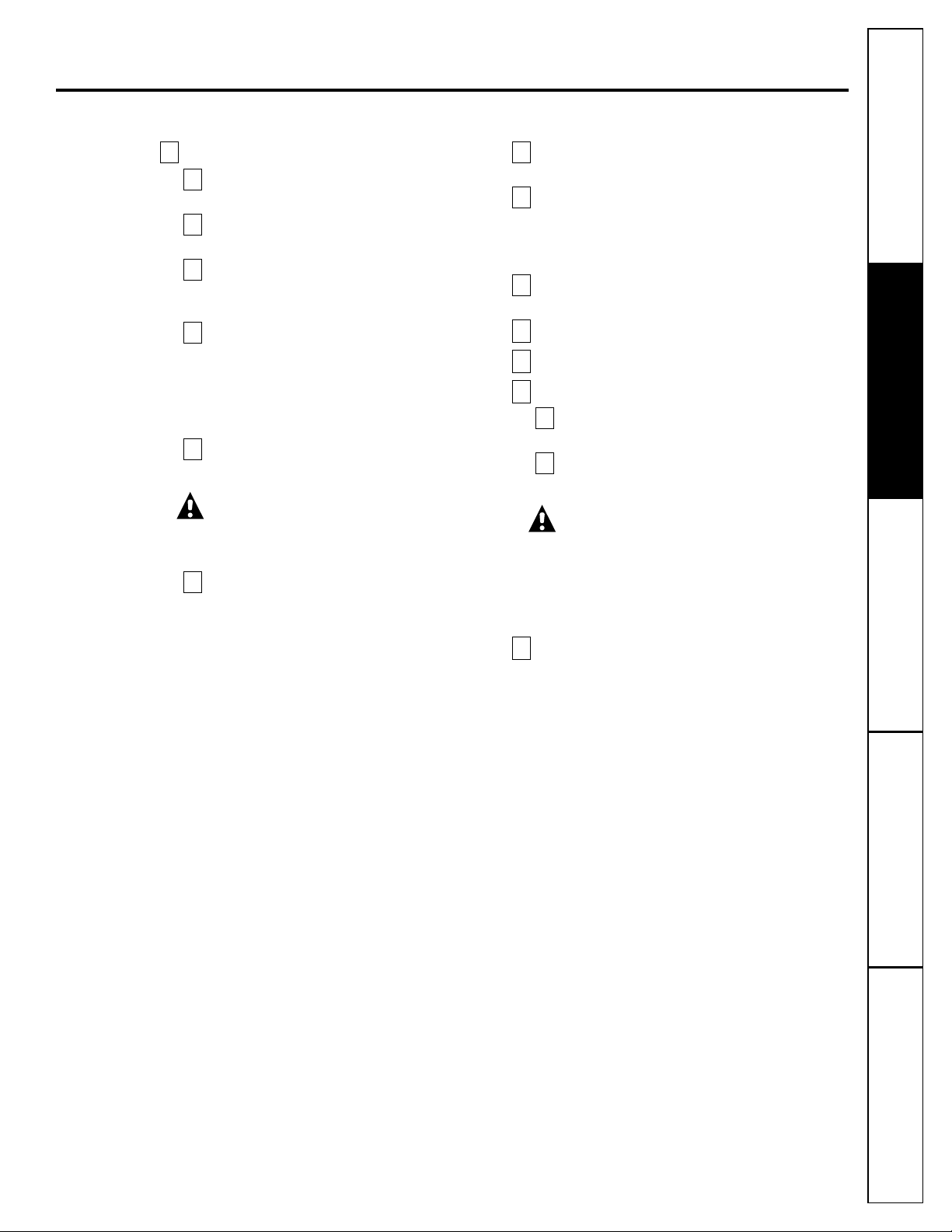
Owner’s Manual
and Installation
Safety Instructions
. . . . . . . . . . . . .2
Operating Instructions
About the RO System . . . . . . . . .4, 5
Specification Guidelines . . . . . . . . .3
Care and Cleaning
Cartridge Replacement . . . . . . . .6, 8
RO Cartridge Replacement
Procedure, Including
Sanitization . . . . . . . . . . . . . .6–9, 18
Installation Instructions
Before Beginning Installation . . . .11
Important Recommendations . . . .10
Step-by-Step Instructions . . . . .12–18
Checklist . . . . . . . . . . . . . . . . . . .18
Drain Connections . . . . . . . .13, 14
Faucet Drain Tubing and
Water Supply Tubing . . . . . . . . .16
Faucet Installation . . . . . . . . . . .15
Feed Water Supply . . . . . . . . . . .12
System Assembly . . . . . . . . . . . . .17
Tools and Materials Required . . . .10
Troubleshooting Tips . . . . . . . . .19
Consumer Support
Consumer Support . . . . .Back Cover
Parts List/Catalog . . . . . . . . . .20, 21
Product Registration . . . . . . . . . . . .2
Warranty . . . . . . . . . . . . . . . . . . . .23
Manuel d’utilisation
et d’installation
Manual del propietario
y instalación
La section française commence à la page 24
Osmose Inversée
Systeme de Filtration
La sección en español empieza en la página 48
Ósmosis Inversa
Sistema de Filtración
GXRV10ABL is Tested and
Certified by NSF International
against NSF/ANSI Standard 58
for claims specified on the
Performance Data Sheet.
Write the model and serial
numbers here:
Model # ______________
Serial # ______________
You can find them on the
sump bracket.
Page 2
IMPORTANT SAFETY INFORMATION.
READ ALL INSTRUCTIONS BEFORE USING.
■ Check with your state and local public works
department for plumbing and sanitation codes.
You must follow these guidelines as you install the
Reverse Osmosis system. Using a qualified installer
is recommended.
■ If house water pressure is over the maximum
(125 pounds per square inch), install a pressure
reducing valve in the water supply line to the
Reverse Osmosis system.
■
Be sure the water supply conforms with the
Specification Guidelines. If the water supply
conditions are unknown, contact your municipal
water company or your local health department
for a list of contaminants in your area and a list of
laboratories certified by your state to analyze
drinking water.
WARNING: Before using the Reverse Osmosis
system for the first time, the system must be
purged. The Reverse Osmosis cartridge contains
a food grade preservative that must be purged
from the system. The preservative will give product
water an unpleasant taste and odor.
■ This product reduces fluoride in drinking water.
Please consult your dentist if you have questions.
WARNING: Do not use with water that is
microbiologically unsafe or of unknown quality
without adequate disinfection before or after the
system. Systems certified for cyst reduction may
be used on disinfected water that may contain
filterable cysts. This Reverse Osmosis unit contains
a replaceable membrane cartridge treatment
component critical for effective reduction of
Total Dissolved Solids. The water should be
tested periodically to verify that the system is
performing satisfactorily. This system is acceptable
for treatment of influent concentrations of no
more than 27 mg/L nitrate and 3 mg/L nitrite in
combination measured as N and is acceptable for
nitrate/nitrite reduction only for water supplies
with a pressure of 280kPa (40 psig) or greater.
■
This system shall only be used for arsenic
reduction on chlorinated water supplies
containing detectable residual free chlorine
at the system inlet. Water systems using an in-line
chlorinator should provide a one-minute chlorine
contact time before the RO System.
SAVE THESE INSTRUCTIONS
READ AND FOLLOW THIS SAFETY INFORMATION CAREFULLY.
■ Install or store where it will not be exposed to
temperatures below freezing or exposed to any
type of weather. Water freezing in the system
will damage it. Do not attempt to treat water
over 100°F.
■ Do not install on HOT WATER. The temperature
of the water supply to the Reverse Osmosis
system must be between the minimum of 40°F.
and the maximum of 100°F. See the Specification
Guidelines.
■ Do Not open the water supply valve until the
pipes have been flushed.
■ Extended non-use of the Reverse Osmosis system.
If the system is not used for one week or more,
open the RO water faucet, allow the system to
drain. Close the RO water faucet and allow the
system to regenerate the water supply.
WARNING: Discard all unused parts and
packaging material after installation. Small parts
remaining after the installation could be a choke
hazard.
■
Sanitize upon installation of the Reverse Osmosis
system and after servicing inner parts, including
replacement of prefilter, postfilter and Reverse
Osmosis cartridge. It is important to have clean
hands while handling inner parts of the system.
See the Sanitizing the Reverse Osmosis System section.
■
This Reverse Osmosis system contains a replaceable
treatment component critical for effective
reduction of total dissolved solids. This product
water shall be tested periodically to verify that the
system is performing satisfactorily. See the About
the Water Test Kit section.
WARNING!
For your safety, the information in this manual must be followed to minimize the risk of
property damage or personal injury.
SAFETY PRECAUTIONS
PROPER INSTALLATION AND MAINTENANCE
This Reverse Osmosis system must be properly installed and located in accordance with the
Installation
Instructions before it is used.
2
Consumer Support Troubleshooting Tips
Operating Instructions
Safety Instructions
Installation Instructions
Page 3
3
Consumer SupportTroubleshooting TipsOperating InstructionsSafety Instructions Installation Instructions
Specification guidelines. www.GEAppliances.com
The system makes a good supply of drinking water each day.
How much it will make depends primarily on these things…
Product – height 16 ″ width 17″ depth 6″
Maximum iron, manganese, hydrogen sulfide (ppm) . . . . . . . . . . . . . . . . . . . . . .<0.1
Chlorine in water supply . . . . . . . . . . . . . . . . . . . . . . . . . . . . . . . . . . . . . . . . . . . . .Allowable
b
Feed water pH limits (pH) . . . . . . . . . . . . . . . . . . . . . . . . . . . . . . . . . . . . . . . . . . . .4–10
Product (quality) water, 24 hours—gallons . . . . . . . . . . . . . . . . . . . . . . . . . . . . . .10.0
a
Process water per gallon of product water, 24 hours—gallons . . . . . . . . . . . . .5
Percent rejection of TDS (new membrane) . . . . . . . . . . . . . . . . . . . . . . . . . . . . . .92
a
Cyst reduction . . . . . . . . . . . . . . . . . . . . . . . . . . . . . . . . . . . . . . . . . . . . . . . . . . . . . .99.95%
Storage tank capacity—gallons . . . . . . . . . . . . . . . . . . . . . . . . . . . . . . . . . . . . . . .1.3
Automatic shutoff control . . . . . . . . . . . . . . . . . . . . . . . . . . . . . . . . . . . . . . . . . . . .yes
Prefilter and postfilter . . . . . . . . . . . . . . . . . . . . . . . . . . . . . . . . . . . . . . . . . . . . . . .(FX12PA) Carbon Block
Reverse Osmosis membrane . . . . . . . . . . . . . . . . . . . . . . . . . . . . . . . . . . . . . . . . .(FX12M) Thin Film Polyamid
Dimensions (inches) . . . . . . . . . . . . . . . . . . . . . . . . . . . . . . . . . . . . . . . . . . . . . . . . .height 16“ width 17” depth 6”
Feed water pressure limits—pounds per square inch (psi) . . . . . . . . . . . . . . . . . . . . . .40–125
c
Feed water temperature limits—minimum/maximum degrees F. . . . . . . . . . . . . . . . . .40–100
Maximum Total Dissolved Solids (TDS)—parts per million (ppm) . . . . . . . . . . . . . . . .2000
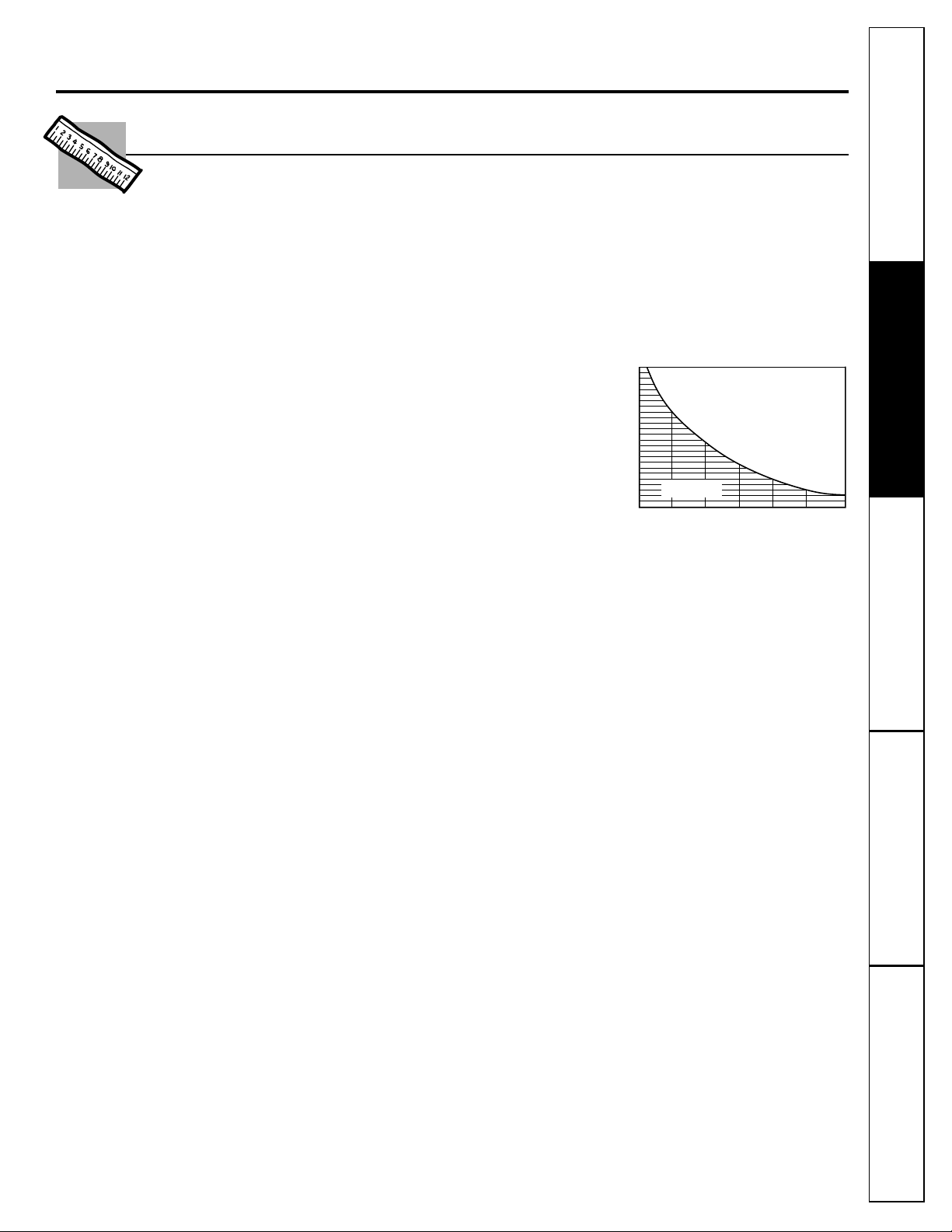
Maximum water hardness @ 6.9 pH recommended to optimize membrane
life—grains per gallon (gpg) . . . . . . . . . . . . . . . . . . . . . . . . . . . . . . . . . . . . . . . . . . . . . . . . .10
For water with hardness greater than 10 grains (at 6.9 pH) the use of a
softener is recommended. Failure to install a water softener will reduce
the life of the Reverse Osmosis membrane. See chart for additional
information on the possible need for a water softener.
a. Tested by NSF International according to ANSI/NSF Standard 58 has given 7.1 GPD. Source
water test parameters are 50 psig, 77°F, pH of 7.5 ± 0.5, and 750 ppm total dissolved solids.
b. Removed (maximum of 2.0 ppm) by the Reverse Osmosis prefilter. REGULAR MAINTENANCE
IS REQUIRED. Chlorine will destroy the Reverse Osmosis membrane.
c. If house water pressure is over 125 psi, install a pressure reducing valve in the water supply line.
If house water pressure is under 40 psi, install a Reverse Osmosis booster pump (contact your
local plumbing supply company).
8
7.5
H
p
7
r
e
t
a
W
g
n
i
6.5
m
o
c
n
I
6
WATER SOFTENER RECOMMENDED
Water Softener
not required
30
2010
INCOMING WATER HARDNESS (GPG)
50
40
60
Page 4
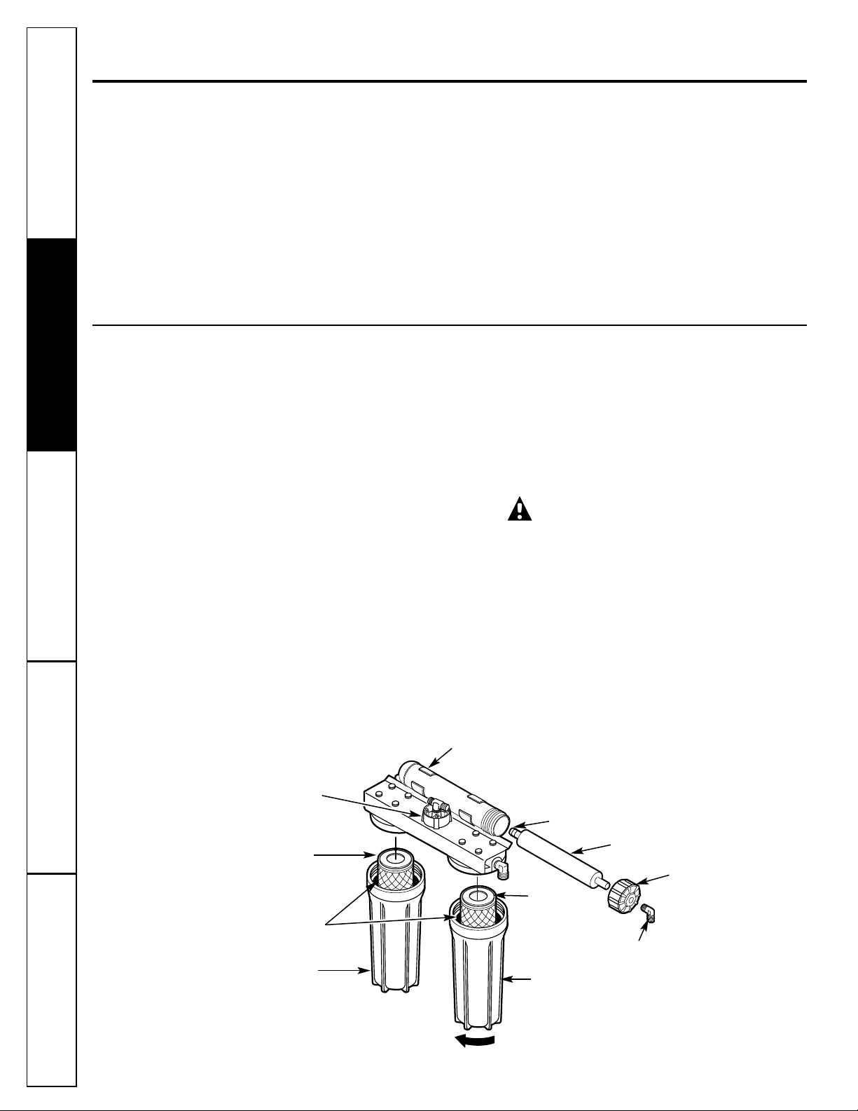
Description of the Reverse Osmosis System
Prefilter—Water from the cold supply pipe is
directed to the prefilter cartridge, which is inside
the sump.
The prefilter is a replaceable sediment
cartridge containing activated carbon. The
cartridge removes sand, silt, dirt, other sediments
and up to 2.0 ppm of chlorine from the feed
water. The prefilter reduces chlorine in the feed
water because CHLORINE DESTROYS THE REVERSE
OSMOSIS MEMBRANE. Filtered, clean, chlorinereduced water flows from the prefilter to the
Reverse Osmosis cartridge.
Storage Tank—The storage area holds up to
1.3 gallons of product water. A diaphragm inside
the tank keeps water pressurized, when the tank
is full, for fast flow to the faucet when drinking
water is needed.
Check Valve—A check valve is built into one end
of the Reverse Osmosis housing. The check valve
prevents a backward flow of product water from
the storage area. A backward flow could cause the
Reverse Osmosis membrane to rupture.
Automatic Shutoff Assembly—To conserve water, the
drinking water system has an automatic shutoff.
When the storage tank has filled to capacity and
the drinking water faucet is closed, pressure closes
the shutoff. Water flow to the Reverse Osmosis
housing is shut off until drinking water is used
again, and pressure drops in the Reverse Osmosis
system.
WARNING: The reverse osmosis system
contains a replaceable component critical to
the efficiency of the system. Replacement of the
reverse osmosis component should be with one
of identical specifications, as defined by the
manufacturer, to assure the same efficiency
and contaminant reduction performance.
4
About the reverse osmosis system.
What the Reverse Osmosis System Does
Reverse Osmosis removes Total Dissolved Solids
(TDS) and organic matter from water by diffusing
it
through a special membrane. The membrane
separates minerals and impurities from the water
and they
are flushed to the drain. High quality
product water goes directly to the drinking water
faucet or to the storage tank. The system makes
a good supply of drinking water each day; see
Specification Guidelines above. How much it makes
depends on the feed water supply pressure,
temperature and quality.
The carbon prefilter and postfilter are replaceable
cartridges. The prefilter removes chlorine while
also filtering sediments. The postfilter removes any
other undesirable tastes and odors before you use
the water.
Troubleshooting TipsConsumer Support Troubleshooting Tips
Installation Instructions
Safety InstructionsOperating Instructions
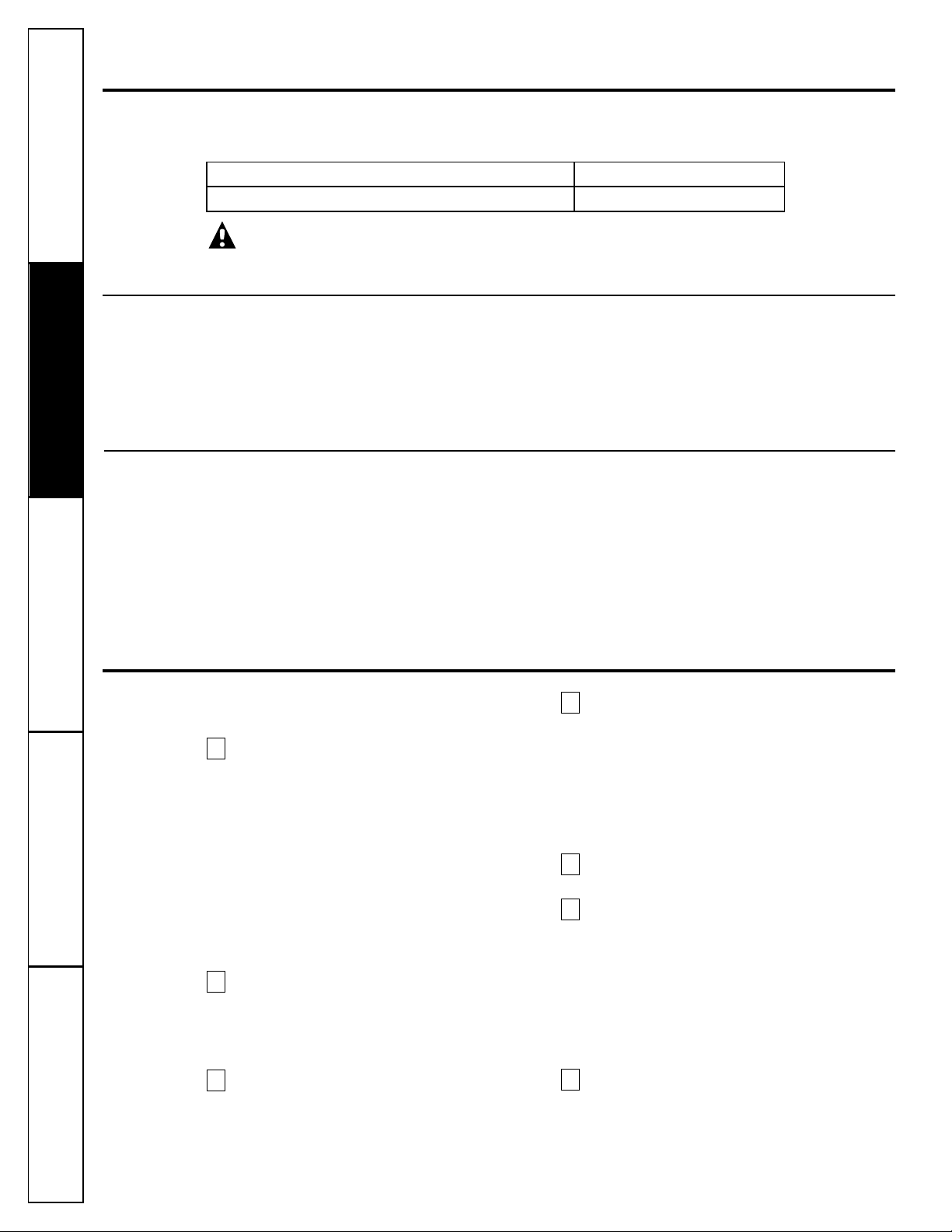
Sump
Sump
Postfilter
cartridge
Prefilter cartridge
Inlet cover
Reverse Osmosis cartridge
Reverse Osmosis housing
Turn sump this way
to remove
O-ring inside sump
Automatic shutoff
assembly
O-ring end
Reverse Osmosis
Housing Cap
Page 5
Reverse Osmosis Cartridge—The cartridge, inside
the Reverse Osmosis housing, includes a tightly
wound, special membrane. Water is forced through
the cartridge where the membrane removes the
dissolved solids and organic matter. High quality
product water exits the Reverse Osmosis housing
and goes to the storage tank. Reject water, with the
dissolved solids and organic matter, leaves the
housing and is discharged to the drain through
1⁄4″ tubing.
Postfilter—After leaving the storage area,
but before going to the system faucet, product
water goes to the postfilter which is inside the
sump. The postfilter is also a replaceable
sediment cartridge that contains activated
carbon. Any remaining tastes, odors or
sediments are removed from product water
by the postfilter. Clean, high quality drinking
water flows through the tubing and to the
system faucet.
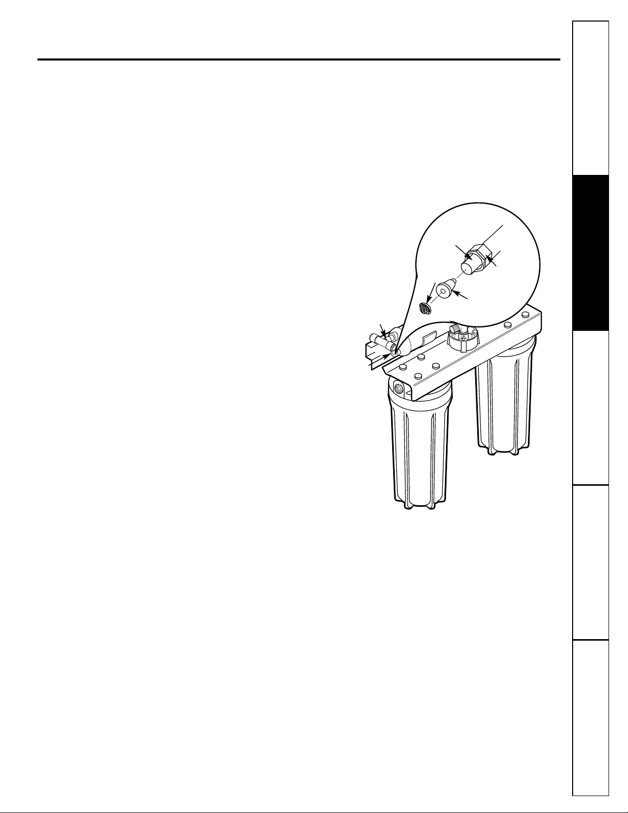
Flow Control—The flow control regulates the flow
of water through the Reverse Osmosis cartridge
at the required rate to produce high quality
water. The control is located in the Reverse
Osmosis housing drain port. A small, coneshaped screen fits over the front end of the flow
control to prevent clogging due to sediments in
drain water. The flow control should be replaced
each time the Reverse Osmosis membrane is
changed.
5
www.GEAppliances.com
Screen
Flow control
1/4″ tubing
Compression
nut
Check
valve tee
Drain elbow
Consumer Support
Troubleshooting Tips
Operating InstructionsSafety Instructions Installation Instructions
T
o
d
rain
Page 6
6
Care and cleaning of the reverse osmosis system.
To obtain replacement filters, call toll-free GE Appliance Parts at 800-626-2002 (U.S.),
800-663-6060 (Canada–English), 800-361-3869 (Canada–French).
CAUTION: Before servicing the Reverse Osmosis system, close the water supply/saddle valve and open
the RO water faucet. Allow the system to drain.
Prefilter/Postfilter Cartridge Replacement FX12P Carbon Block
Reverse Osmosis Cartridge Replacement FX12M Thin Film Polyamide
Prefilter and Postfilter Cartridge Replacement
Follow the steps in the Sanitizing the Reverse Osmosis System section EXCEPT discard the old filters and
replace with new filters.
The Water Test Kit
This Reverse Osmosis system contains a replaceable treatment component, critical for effective
reduction of Total Dissolved Solids (TDS). This product water shall be tested periodically to verify
that the system is performing satisfactorily. Follow instructions included in the kit. Product water
should be tested a minimum of every six months. A replacement test kit will be provided to you with
the results of each test submittal.
Be sure you clean your hands with anti-bacterial
soap before handling inner parts of the system.
Tur n
off
the water supply valve to the Reverse
Osmosis System
. Open the RO water faucet
and leave the storage tank open. Allow the
water in the system to drain completely
(this takes several minutes).
If the Reverse Osmosis Filtration system is
connected to your icemaker, YOU MUST
turn off the icemaker by raising the feeler
arm before servicing the filter, changing the
filters or purging the filtration system. Four
hours after servicing your unit, lower the
feeler arm to resume icemaking.
Pull the Reverse Osmosis System out away
from the cabinet but do not disconnect any
tubing. Place a dry towel under the Reverse
Osmosis Unit to absorb water that will spill
out during disassembly.
Unscrew inlet cover cap to open Reverse
Osmosis housing.
Sanitizing the system is done with the Reverse
Osmosis Cartridge and filter cartridges removed
from the system.
Remove the Reverse Osmosis Cartridge
from the housing by grasping the end of the
cartridge with the clean pliers and pulling
to the right.
NOTE: Water may be discolored when removing the
cartridge—this is NORMAL. Place the cartridge in a
clean plastic bag to protect the cartridge from
damage until it is reassembled.
Reinstall the inlet cover, making sure the
O-ring is in place.
Remove the POSTFILTER sump by turning
it to the left using the sump wrench that was
provided with the Reverse Osmosis System.
Be careful when removing the sump because
it is full of water. Remove the old filter
cartridge from the sump and discard. Inspect
the sump. Make sure the O-ring is seated in
the top of the sump. Reinstall the sump
(without the cartridge) to sanitize.
Remove the PREFILTER sump using the
sump wrench and discard the old cartridge.
Make sure the O-ring is seated in the top of
the sump.
7
6
5
4
3
2
1
Consumer Support
Troubleshooting Tips Operating Instructions Safety InstructionsInstallation Instructions
Care and cleaning—RO cartridge replacement procedure,
including sanitization.
Page 7
Sanitize the system.
CAUTION: Before adding the sanitizing
agent, be sure to remove all cartridges as
described above. Chlorine will destroy the
Reverse Osmosis Cartridge. Sanitizing the
system is done with the reverse osmosis
cartridge and filter cartridges removed
from the system.
Before reinstalling the PREFILTER
sump, fill this sump with cold water to
about 1″ from the O-ring. Add one
ounce (two tablespoons) of ordinary
5.25% household chlorine bleach
(Hilex, Clorox, etc.) and mix into the
water. DO NOT ADD CHLORINE FIRST.
Concentrated chlorine may damage plastic.
Carefully reinstall the sump onto the
Reverse Osmosis System and tighten
securely by hand.
Close the RO water faucet and turn on
the water supply valve to the system.
Allow system to fill for one minute.
NOTE: Various sounds will occur during the
sanitizing. DO NOT USE WATER DURING
SANITIZATION.
Open the RO water faucet, locking the
lever upward against the spout. Allow
water to flow through the Reverse
Osmosis system until all bleach odor
is gone (approximately 20 minutes).
Turn off the water supply valve to the
system, but leave the RO water faucet
open. When the flow of water stops,
proceed to Step 9
.
Be sure hands have been cleaned with antibacterial soap. Repeat Steps 3–6 and 8b;
however, reinstall the Reverse Osmosis
Cartridge from the bag and the new
PREFILTER and POSTFILTER instead of
removing them. Lightly lubricate the inlet
cover and sump O-rings with clean silicone
grease only.
NOTE: The Reverse Osmosis Cartridge is
notched and may need to be rotated during
reinstallation for proper fit.
Turn on water supply valve to the Reverse
Osmosis System and allow approximately
four hours for the system to regenerate and
stabilize. Check the system for leaks. The
system may make some sounds during this
period. This is normal.
Replace the “AA” alkaline batteries in
the control box. Good batteries are necessary
to ensure proper indicator light operation.
Weak batteries may give a false indication.
Batteries should be changed every six months.
Before first use after filter changes, purge the
system by opening RO water faucet for one
minute to remove any harmless carbon
particles. If the system is connected to your
refrigerator icemaker, reset the icemaker
feeler arm to the on (down) position after
the four-hour regeneration period.
12
11
10
9
e
d
c
b
a
8
7
Consumer SupportTroubleshooting TipsOperating InstructionsSafety Instructions Installation Instructions
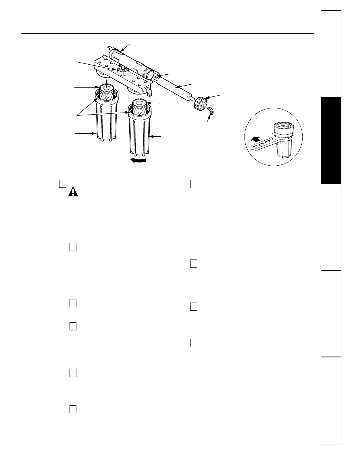
Sump
Sump
Postfilter
cartridge
Prefilter
cartridge
Inlet cover
Reverse Osmosis
cartridge
Reverse Osmosis housing
Turn sump this
way to remove
O-ring
inside
sump
Reverse Osmosis
housing cap
Automatic
shutoff
assembly
Loosen
Sump wrench
O-ring end
www.GEAppliances.com
Page 8
8
Consumer Support
Troubleshooting Tips Operating Instructions Safety InstructionsInstallation Instructions
NOTE: When replacing the Reverse Osmosis
cartridge, also install a new flow control and screen.
See the Flow Control and Screen section.
If the Reverse Osmosis Filtration system is
connected to your icemaker YOU MUST turn off the
icemaker by raising the feeler arm before servicing
the filter, changing the filters or purging the
filtration system. Four hours after servicing your
unit, lower the feeler arm to resume icemaking.
Be sure you clean your hands with anti-bacterial
soap before handling inner parts of the system.
Turn off the water supply valve to the Reverse
Osmosis system (turn clockwise)
and open the
RO
water faucet. Allow the system to drain
completely (this takes several minutes).
C
AUTION:
Failure to close the water supply valve
will cause water to spray or run when sumps
are removed.
Pull the Reverse Osmosis system out away
from cabinet. Leave tubing connected. Place
a dry towel under the Reverse Osmosis unit.
Unscrew inlet cover cap to open Reverse
Osmosis housing.
Use pliers to pull the cartridge from the
housing and discard the cartridge.
Sanitize the system. Go to Filter Change
Procedure, including sanitization section.
Complete Steps 5 – 9. However, place filters in
clean plastic bag and reinstall them at Step 9.
5
4
3
2
1
Reverse Osmosis Cartridge Replacement
Care and cleaning—RO cartridge replacement procedure,
including sanitization.
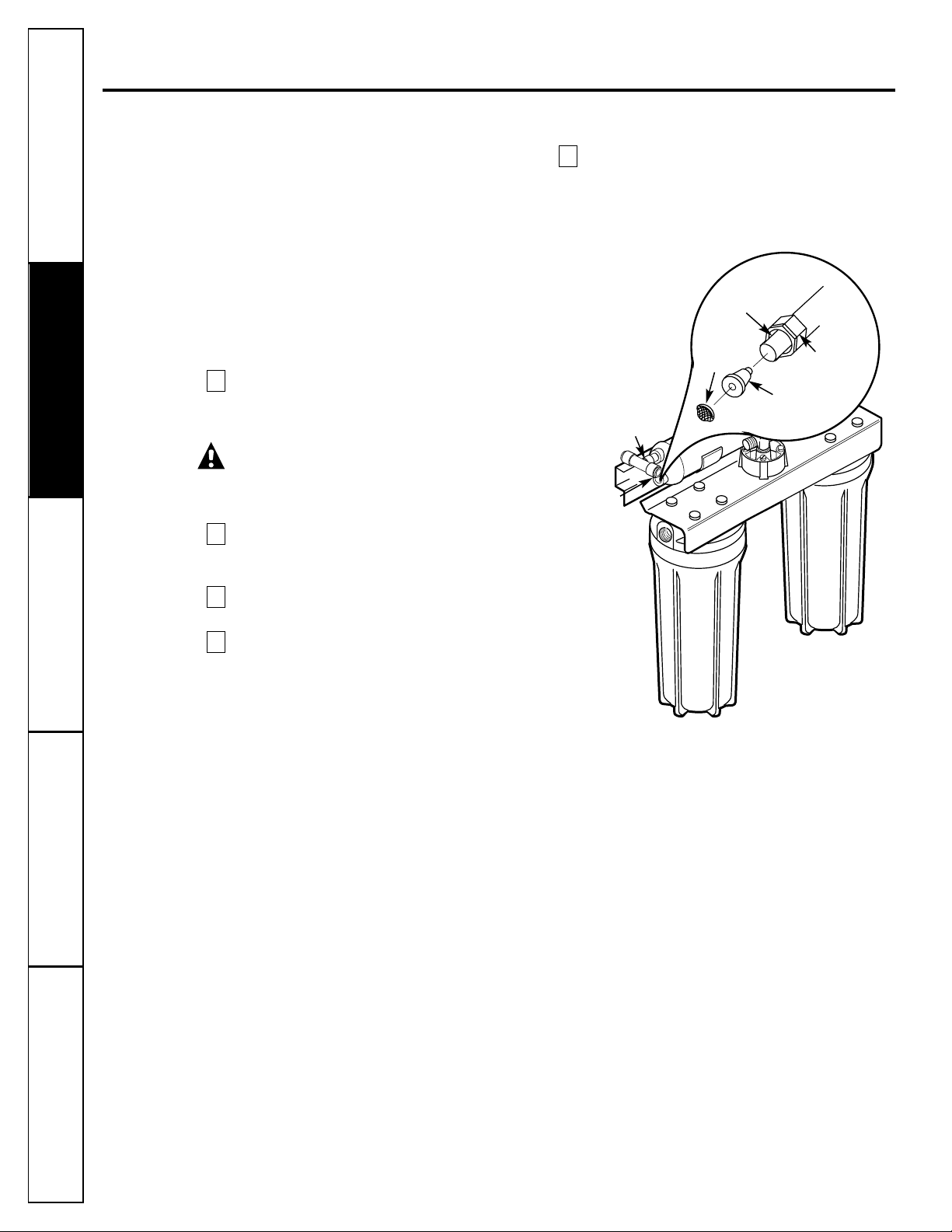
Screen
Flow control
1/4″ tubing
Compression
nut
Check
valve tee
Drain elbow
To
dra
in
Page 9
Install new flow control and screen.
Locate the plastic drain elbow, next to
the brass check valve tee.
Unscrew the compression nut.
Remove flow control with a clean knife
edge. Remove screen; a toothpick may be
needed.
If you are replacing the flow control and
screen,
discard them. If you are checking
the flow control,
screen and tubing for
blockage, clean these parts of any debris.
Do not blow through the flow control,
it will contaminate the part.
Replace the screen by placing the cone
end into the elbow cap and carefully
push it in.
C
AUTION: Do not force in further after you
feel resistance. Visually check to be sure it
is properly positioned.
I
nstall flow control and tighten
compression nut by hand, then another
1/4 turn with pliers. DO NOT OVERTIGHTEN
AND DISTORT OR CRUSH THE TUBING AND
FLOW CONTROL.
Unscrew the inlet cover cap from the housing
to remove.
Install the new Reverse Osmosis cartridge.
NOTE: The Reverse Osmosis cartridge o-ring end
is notched and may need to be rotated during
reinstallation for proper fit.
Lightly lubricate the O-ring seal with only
clean silicone grease.
Replace the inlet cover.
Turn on the water supply. Check for leaks.
Purge the Reverse Osmosis system.
Open the RO water faucet until the tank
is empty and flow stops.
After filling and emptying the storage
tank four times, the system is ready to
make product water for your use.
CAUTION: The Reverse Osmosis cartridge
contains a food grade preservative that should
be purged from the system before first use or
whenever the Reverse Osmosis cartridge is
replaced. The preservative will give product
water an unpleasant taste
and odor.
Turn icemaker back on by lowering the
feeler arm.
13
b
a
12
11
10
9
8
7
f
e
d
c
b
a
6
Consumer Support
Troubleshooting TipsOperating Instructions
Safety Instructions
Installation Instructions
9
www.GEAppliances.com
Page 10
• Battery Powered Cordless Drill
• 1/4″ Drill Bit
• 1-1/4″ Drill Bit (type as required) if mounting is needed for faucet
• Adjustable Open-End Wrenches
• Phillips and Straight Screwdrivers
• Utility Knife
• Contents Included with the Product:
— Reverse Osmosis Assembly
— Product Literature (Owner’s Manual and Installation, Use and Care Video,
Performance Data Sheet and Owner Registration Card)
— Water Supply Valve Parts Bag
— Drain Line Adapter
—27″ Length of 3/8″ Tubing
— Storage Tank
— Filter Replacement Reminder Label
— Water Test Kit
INSTALLER RESPONSIBILITY: The water supply valve (see the Feed Water Supply section) is
included for use in areas where codes permit. Installer must comply with state and/or local codes.
If not, the installer must provide fittings to tap the cold water pipe for a feed water source to the
Reverse Osmosis system (must adapt to 1/4″ OD tubing).
Installation instructions.
Important Installation Recommendations
Read entire manual. Failure to follow all guides and rules could cause personal injury or
property damage.
• BE SURE TO FOLLOW ALL APPLICABLE STATE AND LOCAL CODES.
• Use a qualified installer.
• Do not install the Reverse Osmosis system outside or in extreme hot or cold temperatures.
DO NOT INSTALL ON HOT WATER.
• Recommended installation is under the sink. However, the unit can be installed in a remote
location, up to 30 feet away from the sink. Additional installation materials may be required.
• If Reverse Osmosis system is connected to a refrigerator icemaker, a special icemaker connection
kit is required (RVKIT). Do not use copper tubing for the connection between the Reverse
Osmosis system and the refrigerator.
• Be sure the water supply conforms to the specifications; see the Specifications Guidelines section.
If water supply conditions are unknown, contact your municipal water company or your local
health department for a list of
contaminants in your area and a list of laboratories certified by
your state to analyze drinking water.
WARNING: Do not use with water that is microbiologically unsafe or of unknown quality without
adequate disinfection before or after the system. Systems certified for cyst reduction may be used on
disinfected water that may contain filterable cysts. This system shall only be used for arsenic reduction
on chlorinated water supplies containing detectable residual-free chlorine at the system inlet. Water
systems using an in-line chlorinator should provide a one minute chlorine contact time before the RO
system.This Reverse Osmosis system contains a replaceable treatment membrane cartridge critical for
effective reduction of Total Dissolved Solids. The water should be tested periodically to verify that the
system is performing satisfactorily. This system is acceptable for treatment of influent concentrations
of no more than 27 mg/L nitrate and 3 mg/L nitrite in combination measured as N and is certified for
nitrate/nitrite reduction only for water supplies with a pressure of 280kPa (40 psig) or greater.
Small parts remaining after the installation could be a choke hazard. Discard safely.
Tools and Materials Required for Installation
10
Consumer Support
Troubleshooting Tips Operating Instructions Safety InstructionsInstallation Instructions
Page 11
11
Consumer SupportTroubleshooting TipsOperating InstructionsSafety Instructions Installation Instructions
Things to Check Before Beginning Installation
FEED WATER—The water supply to the undercounter
Reverse Osmosis system must have the qualities listed
in the specifications (see the Specifications Guidelines
section). Municipal water supplies most often will have
these qualities. Well water may need conditioning—
have the water tested by a water analysis laboratory
and get their recommendations for treatment.
CAUTION: For water with a hardness greater
than 10 grains (at 6.9 pH), the use of a softener is
recommended.
Failure to install a softener will reduce
the life of the Reverse
Osmosis membrane. See the
Specifications Guidelines section for additional
information on the possible need for a softener.
DRAIN POINT*—A suitable drain point and air gap
(check your local codes) are needed for reject water
from the Reverse Osmosis membrane cartridge.
RO FAUCET—The RO product water faucet installs on
the sink or on the countertop next to the sink. Often,
it is installed in an existing sink spray attachment hole.
Space is required underneath for tubing to and from the
faucet, and for securing the faucet in place. All faucet
connections and installation procedures are done on or
above the sink or countertop. Refer to Fig. 1 below.
BASEMENT INSTALLATION—If installing in a basement,
leave enough tubing in place during installation to be
able to move unit to floor for ease at servicing and
making filter/membrane changes.
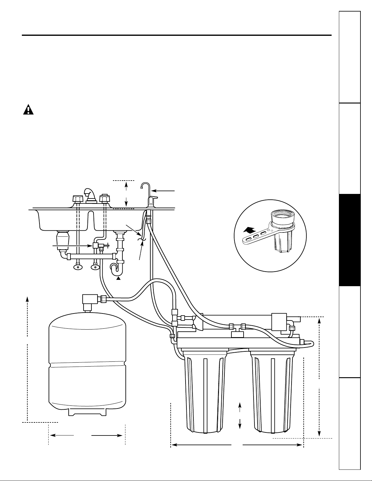
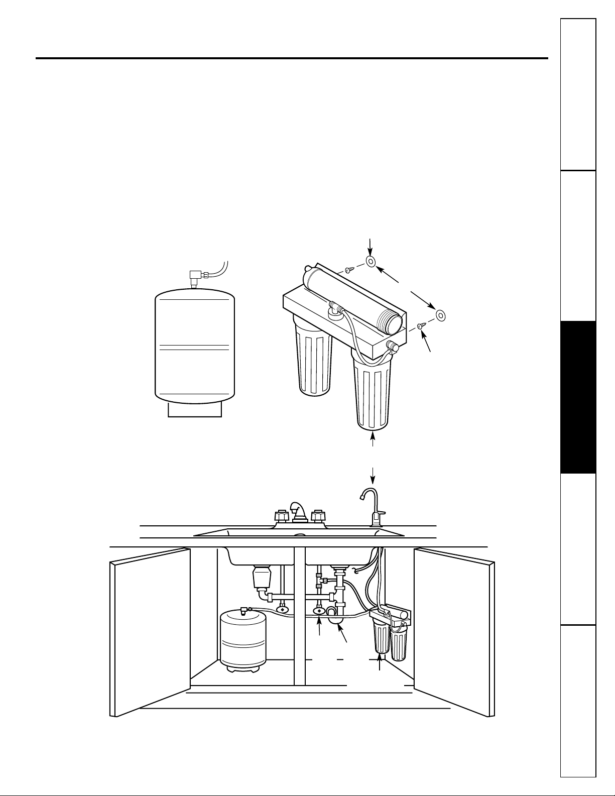
Fig. 1. INSTALLATION
OVERVIEW
Sump wrench
provided
RO product water faucet
mounted through sink
3/8″
drain tubing
Water supply
valve or
compression
fitting
Hot Cold
Sink p-trap
Drain line*
6-1/4″
15″
16″
9″ dia.
17″
Depth
5 1⁄ 2″
Reverse Osmosis system
Storage tank
*For drain line options see Filtration Drain Connection Installations section.
Page 12
12
Consumer Support Troubleshooting Tips
Operating Instructions
Safety Instructions
Installation InstructionsInstallation Instructions
Step-by-step installation instructions.
Feed Water Supply
Check and comply with local plumbing codes as you plan, then install a cold feed water supply fitting.
For new home installation using standard plumbing fittings, see first two illustrations below.
A typical installation for existing homes using the saddle valve is shown in third illustration below.
A. PREFERRED INSTALLATION
Turn off the cold water supply.
Complying with plumbing codes, install a fitting on the cold water pipe to adapt 3/8″ OD tubing.
A typical connection is shown in illustrations at right (parts not included). Make sure a water
supply valve is used.
2
1
B. OPTIONAL HOME INSTALLATION Where codes permit
*For 1/2 ″ OD or larger metal tubing only.
NOTE: Codes in the state of Massachusetts require installation by a licensed plumber and do not permit the
use of the saddle valve. For installation, use plumbing code 248-CMR of the Commonwealth of Massachusetts.
Turn off the cold water supply and attach saddle valve as shown in illustration at right.
DANGER: To protect yourself from serious injury or fatal shock, use a battery-powered hand drill
only to make the hole. DO NOT USE AN ELECTRIC DRILL.
Close the water supply valve by turning the handle clockwise.
Open the main water supply valve and several house faucets to purge air from the system.
Close faucets when water runs smoothly.
3
2
1
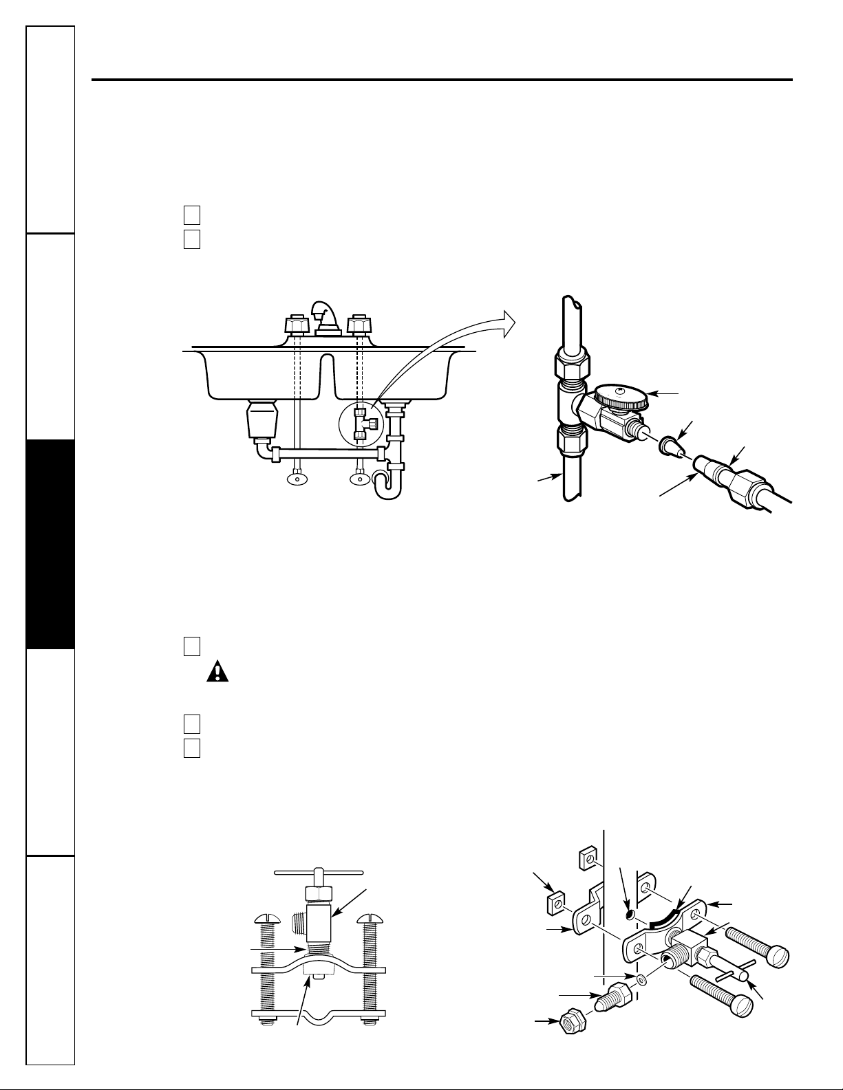
Optional water supply connection (using saddle valve)*
Pre-drill
1/4″ hole
Seal—make sure the
seal is in place
Clamp X
Nut (2)—not
required if holes
in clamp are
threaded
Valv e
Handle
Tubing adapter
Washer
Compression nut
Clamp Z
Preferred water supply connection
(using compression fitting)
Insert (not included)
Cold
water
pipe
3/8″ tubing to inlet
Ferrule
Water supply valve
Typical location
Cold
water
Use to connect the tubing
*For 1/2 ″OD or larger metal tubing only.
Snug valve into bracket
DO NOT OVERTIGHTEN
Some threads
should be visible
Rubber gasket
Fig. 2A.
Fig. 2B.
Page 13
Consumer SupportTroubleshooting TipsOperating InstructionsSafety Instructions Installation Instructions
13
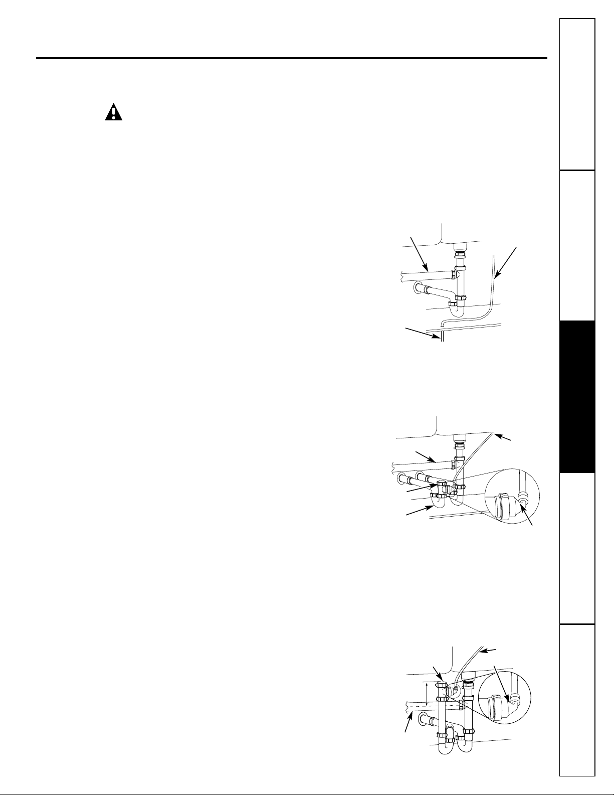
Filtration Drain Connection Installations
Check and comply with all state and local plumbing codes as you plan.
CAUTION: The options detailed below are the ONLY approved installation configurations. Do not use any
drain saddle device.
NOTE: Failure to follow these Installation Instructions will void the Warranty, and the Installer will be
responsible for any service, repair or damages caused thereby.
Fig. 3A.
Fig. 3B.
Fig. 3C.
From second sink
or disposer
From second sink
or disposer
From second
sink or disposer
From
faucet
air gap
Drain line from
Reverse Osmosis
by-passing faucet
air gap
Maintain air gap
at drain point in
basement
Drain line adapter
Separate p-trap
Cap (not
included)
4″
Min.
From faucet
air gap
Drain line adapter
Preferred Installation Options
(Options A, B and C)
OPTION A.
BASEMENT ACCESS INSTALLATION (Fig. 3A)
Route the drain line DIRECTLY from the Reverse Osmosis
system to a standpipe in the basement, by-passing the air
gap provided in the faucet. The drain line may also be
routed in the basement to a floor drain or washtub,
provided that the air gap in the basement is maintained.
Avoid dips, loops or low spots in the drain line. The
basement air gap and drain installation configuration
must conform to all local codes. Special air gap fittings
are available to connect the drain line to the top of the
standpipe.
OPTION B.
SEPARATE VENT INSTALLATION—
2 P-TRAP (DRY-VENTED) (Fig. 3B)
Install a separate dry-vented p-trap under the sink to
be used exclusively for the Reverse Osmosis drain line.
A dry-vented p-trap is a p-trap that has its own vent/stack.
Attach the provided drain line adapter to the p-trap and
secure it with the slip joint nut and washer as shown.
Route the drain line from the air gap to the drain line
adapter ensuring that there are no dips, loops or low
spots in the line, which could result in a clogged drain
line. The drain line adapter should be aligned vertically
such that the hose connection points in a direction 45°
off vertical. (See Fig. 3E.) The drain line must be routed
through the air gap provided in the RO water faucet.
OPTION C.
SHARED VENT INSTALLATION—
2 P-TRAP (WET-VENTED) (Fig. 3C)
Install a p-trap under the sink to be used exclusively for
the Reverse Osmosis drain line. A wet-vented p-trap is a
p-trap that shares a common vent/stack. Attach the
provided drain line adapter to the p-trap and secure it
with the slip joint nut and washer as shown. Route the
drain line from the air gap to the drain line adapter
ensuring that there are no dips, loops or low spots in the
line, which could result in a clogged drain line. The drain
line adapter should be aligned vertically such that the
hose connection points in a direction 45° off vertical.
(See Fig. 3E.) The drain line must be routed through the
air gap provided in the RO water faucet. Locate the p-trap
as high as possible (minimum of 4″ above horizontal pipe
from second sink or disposer).
Cap (not
included)
Page 14
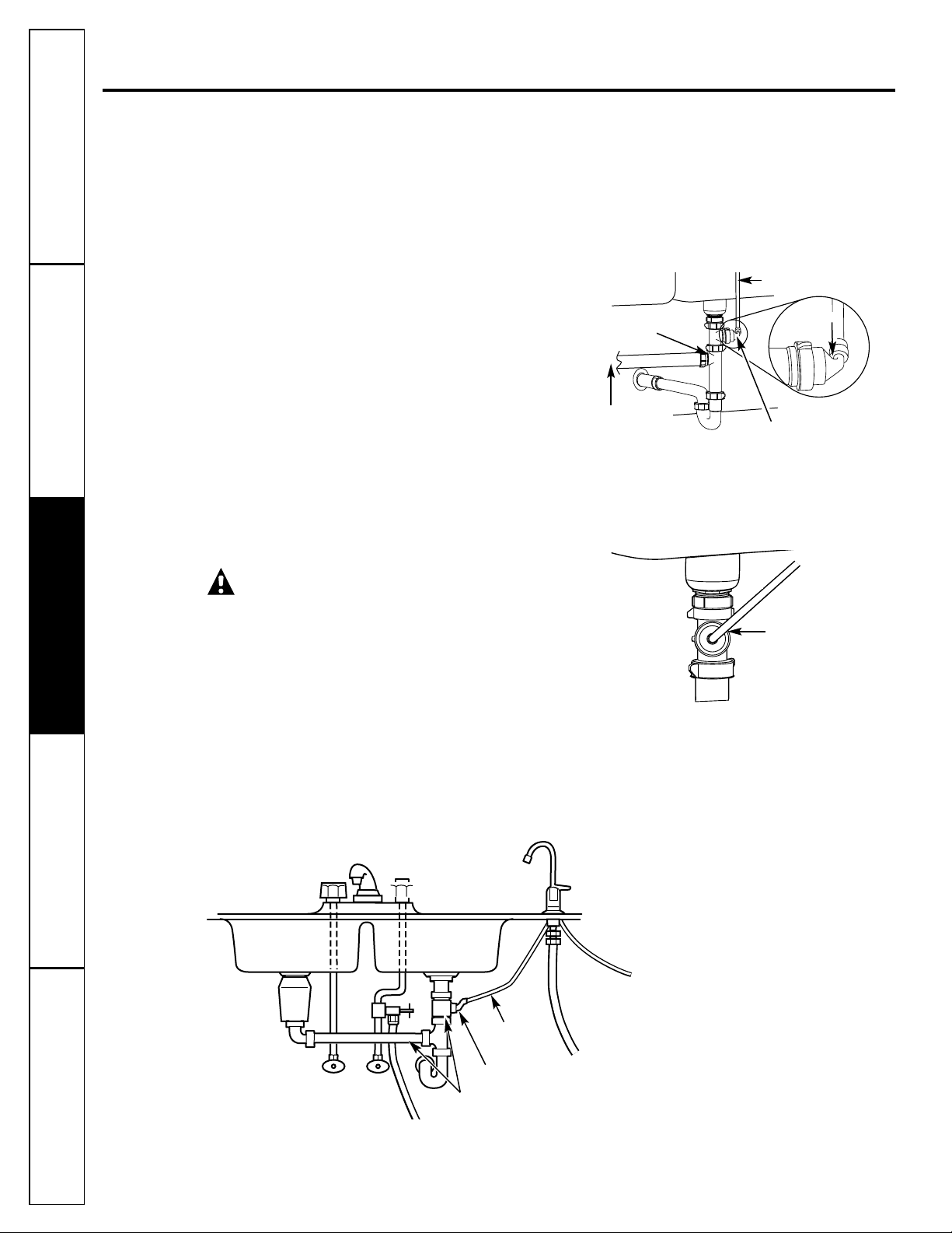
Filtration Drain Connection Installations
Secondary Recommendation
(Use only if option A, B or C on page 13
is not possible.)
OPTION D.
DRAIN LINE ADAPTER INSTALLATION (Fig. 3D)
DO NOT install the drain line downstream of a
disposal or in a horizontal pipe. Install the provided
drain line adapter under the sink as shown.
The baffle-tee or y-connector shown must be in place
(purchase and install if necessary) to prevent a clog in
the Reverse Osmosis drain line. Route the drain line
from the air gap to the drain line adapter ensuring
that there are no dips, loops or low spots in the line,
which could result in a clogged drain line. The drain
line adapter should be aligned vertically so that the
hose connection points in a direction 45°off vertical.
(See Fig. 3E.) This installation MAY result in a slight
drain noise in the sink drain when the Reverse
Osmosis system is operating. Rotate the Drain Line
adapter tee assembly slowly until noise is minimized.
Generally, 180° opposite the existing horizontal
pipe/baffle-tee is a good orientation.
CAUTION!
DO NOT INSTALL DRAIN LINE ADAPTER
DOWNSTREAM FROM DISPOSER.
When installed, the tubing must not have any dips,
kinks, loops, etc. The tubing must be cut to length
to provide a straight routing from the faucet to the
drain (Fig. 3F). See instructions in the “Filtration
Drain Connection Installation” section for details
and options.
INCORRECT INSTALLATION WILL RESULT IN WATER
BACK-UP IN THE DRAIN LINE, WHICH WILL LEAK AT
THE FAUCET!
Fig. 3D.
Fig. 3E.
Mandatory baffle-tee
or y-connector
From second
sink or disposer
45°
From faucet air gap
Drain line
adapter
Drain line connection should
be 180°
opposite existing horizontal
pipe/baffle-tee as shown in diagram
Drain line adapter
Proper drain line adapter orientation.
Step-by-step installation instructions.
Consumer Support Troubleshooting Tips
Operating Instructions
Safety Instructions
Installation InstructionsInstallation Instructions
14
Fig. 3F.
Drain line adapter
Drain line
is straight
Drain line adapter
in different line
from disposer
Disposer
HOT
COLD
Page 15
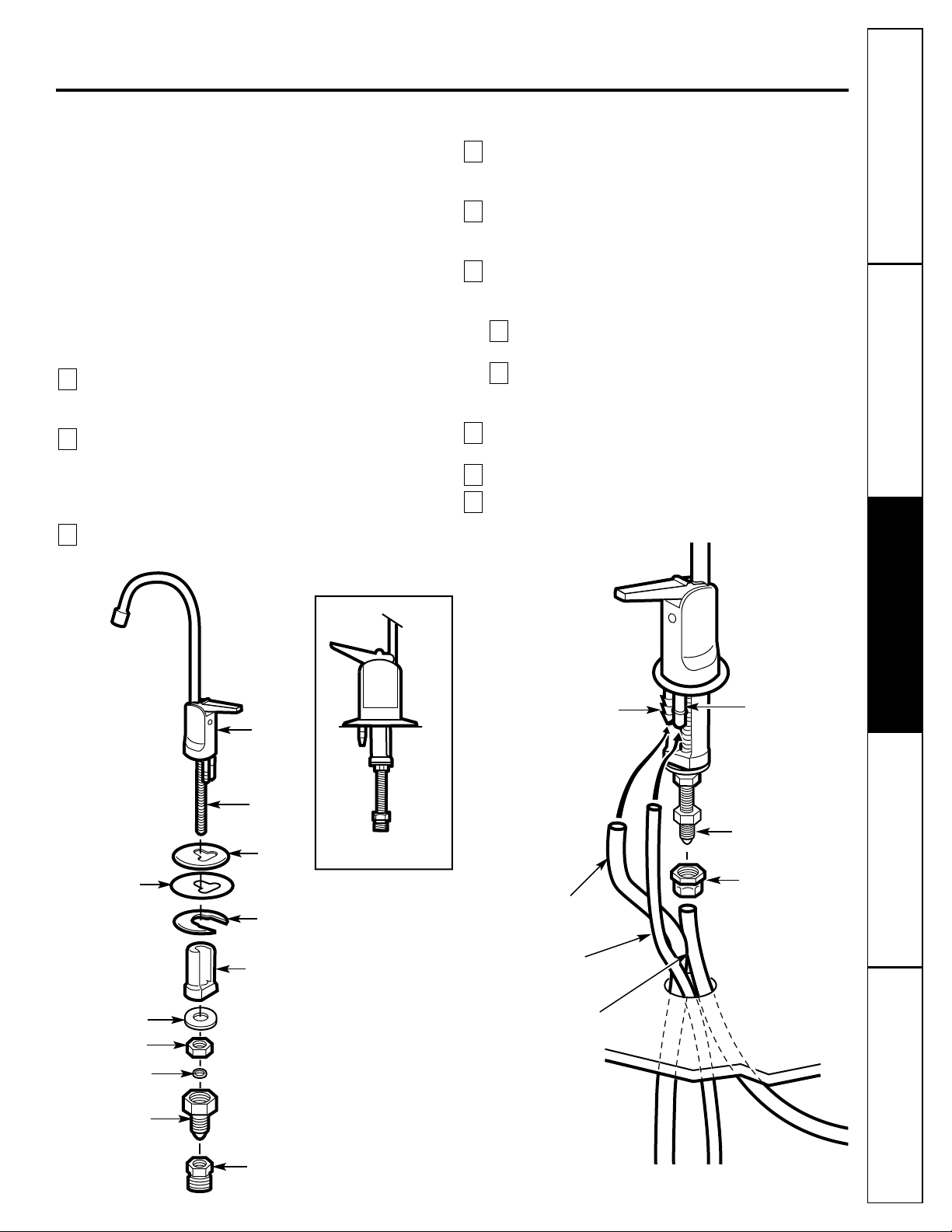
Fig. 4A.
Spacer
Mounting plate
Base
Hex nut
Lever
Spout
Faucet
stud
Large gasket
Compression nut
Metal washer
Tubing adapter
ASSEMBLED
Consumer SupportTroubleshooting TipsOperating InstructionsSafety Instructions Installation Instructions
15
Faucet Installation
Be sure there is room underneath the sink to make the
needed connections. Select one of the following places
to install the faucet:
—IN an existing sink spray attachment or soap
dispenser hole.
—IN a hole to be drilled in the sink top.
—IN a hole to be drilled in the countertop,
next to the sink.
NOTE: Looking at Fig. 4B, be sure the faucet base will fit
flat against the surface at the selected location so the
gasket will seal.
If drilling is needed, make a 1-1/4″ dia. hole.
Be sure to use the proper procedure for drilling
porcelain or stainless steel.
Place base on threaded stem (flange facing down).
Next, place large gasket on threaded stem, making
sure the stem and two barbed studs fit through the
gasket. Place spacer on stud (open end up) followed
by metal washer and hex nut (Fig. 4A).
Insert washer into tubing adapter. Securely tighten
to faucet stud.
Take the 27″ length of 3/8″ tubing and push one
end completely onto the 3/8″ faucet barb fitting
(Fig. 4B).
Position the Reverse Osmosis system under the sink.
Referring to Fig. 5, on the next page, hang the
system on cabinet wall.
Route the 1/4″ tubing (marked “1⁄4″ BARB ON
FAUCET”) and the 3/8″ tubing (marked “FAUCET”)
up through the mounting hole:
Push one end of the 1/4″ tubing onto the 1/4″
barb on the faucet.
Using the compression nut, fasten the 3/8″ tubing
to the tubing adapter and tighten the nut. Make
sure the tubing is completely seated in the adapter.
Remove the short shipping tube and insert the spout
into the faucet body.
Lower the faucet assembly through the sink.
Under the counter, place the mounting plate above
spacer and securely tighten the hex nut.
9
8
7
b
a
6
5
4
3
2
1
Fig. 4B.
Faucet
NOTE: For ease of service and
maintenance, keep tubing
lengths long enough so removal
of the Reverse Osmosis system
from under the sink is possible.
Tubing adapter
Plastic washer
1/4″ barb fitting
3/8″ tubing,
27″ long
3/8″ barb fitting
3/8″ tubing
marked FAUCET
1/4″ tubing
marked 1/4″ barb
Compression nut
To drain
From RO
From RO
Page 16
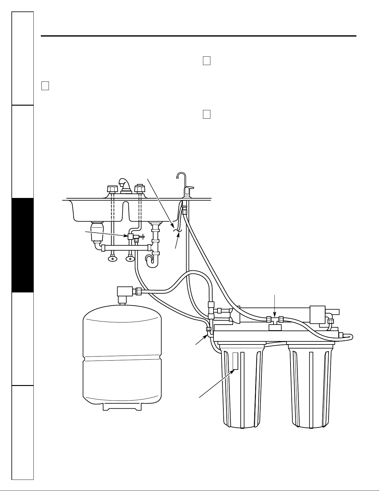
Faucet Drain Tubing and Water Supply Tubing
If Option A, BASEMENT ACCESS INSTALLATION, see
Filtration Drain Connection Installations section,
was used, go to step 2.
If Option B, C or D from page 13 or 14 was used,
connect the faucet drain tubing by running the 27″
length, 3/8″ tubing from the 3/8″ faucet barb to the
drain fitting (installed in Filtration Drain Connection
Installations section). Keep this tubing run as short
and straight as possible, without loops, dips or
low-spots. Cut the tubing as needed and insert
into the drain fitting (see Fig. 3B, 3C or 3D in the
Filtration Drain Connection Installations section).
To connect the water supply tubing: Run the 1/4″
tubing (marked “WATER SUPPLY”) from the
Reverse Osmosis inlet to the feed water supply fitting
(see Fig. 2A or 2B, in the Feed Water Supply section).
Connect the tubing as applies (Fig. 2A or 2B, in the
Feed Water Supply section) and tighten the nut
securely (use Teflon Tape
TM
to prevent leaks).
Apply the Filter replacement reminder label to
one of the filter sumps between the ribs. Mark the
date for filter replacement six months from the
installation date.
3
2
1
Fig. 5.
3/8″
drain tubing
Drain line*
Water supply valve or
compression fitting
Hot Cold
Automatic shutoff assembly
Storage tank
* For drain line options see Filtration Drain Connection
Installations section.
RO inlet
Filter Replacement
Reminder Label
16
Step-by-step installation instructions.
Consumer Support Troubleshooting Tips
Operating Instructions
Safety Instructions
Installation InstructionsInstallation Instructions
Page 17
Consumer SupportTroubleshooting TipsOperating InstructionsSafety Instructions Installation Instructions
17
Reverse Osmosis System Assembly and Storage Tank Installation
1. Hold the Reverse Osmosis assembly up to the wall surface where you will install it. Mark locations
for the hanger washers and screws.
2. Fasten the hanger washers to the wall surface. Wood screws are included for fastening to a wood
surface. Provide other screws as needed.
3. Hang the Reverse Osmosis assembly on the hanger washers.
4. Connect the tubing to the storage tank: Run the length of 3/8″ tubing (marked “STORAGE TANK”)
from the tee fitting on the Reverse Osmosis module to the tank shutoff valve. Use Teflon TapeTMto
prevent leaks.
Fig. 6A.
Storage tank
Hanger
washer
(2)
Screw
(2)
1
0
″
2″ minimum clearance for
changing cartridges
Fig. 6B.
RO faucet
Reverse Osmosis
system
Cold
water
supply
Sink
p-trap
Storage tank
*For drain line options see Filtration Drain Connection Installations section.
Page 18
Now That Your Reverse Osmosis System is Installed…Sanitize
Sanitize upon installation and after servicing inner parts, including replacement of prefilter,
postfilter and the Reverse Osmosis cartridge. It is important to wash hands with anti-bacterial soap
before handling inner parts of the system. See the Sanitizing the Reverse Osmosis System section.
CAUTION: If installing unit in New Construction, ensure house plumbing is flushed thoroughly before
opening the water supply valve. Also, before sanitizing, be sure to remove all cartridges as described in
the
Sanitizing the Reverse Osmosis System section
. Chlorine will destroy the Reverse Osmosis cartridge.
Complete Cartridge Replacement and Sanitize the System procedures (see pages 6–8), except reinstall
the filters provided with the unit.
Purge membrane. See Step 12 in Reverse Osmosis Cartridge Replacement section.
Carefully check the system for leaks.
3
2
1
Installation Checklist
1. Are all tubing connections tightened? Do they run between the points shown? No leaks!
2.
Did you use drain option B, C or D? Make sure the 3/8″ drain tubing, from the faucet to the drain
point, is without loops, dips or low spots.
3. Is the water supply shutoff valve open?
4. Did you sanitize and purge the system?
18
Step-by-step installation instructions.
Consumer Support
Troubleshooting Tips Operating Instructions Safety InstructionsInstallation InstructionsInstallation Instructions
Page 19
Consumer SupportTroubleshooting TipsOperating InstructionsSafety Instructions Installation Instructions
19
Before you call for service… www.GEAppliances.com
Problem Possible Causes What To Do
Sounds you might hear Running water from the unit • This is normal.
to a drain.
Water has air bubbles Air in system after installation. • Will go away after water runs for a while.
and is cloudy
Chlorine taste and/or The ppm of chlorine in your
• If the water supply contains more than 2.0 ppm of
odor in the Reverse water supply exceeds maximum
chlorine,
additional filtering of the water supply to the
Osmosis product water limits and has destroyed the Reverse Osmosis is needed. Correct this condition before
Reverse Osmosis membrane. doing maintenance on the Reverse Osmosis system.
The prefilter is no longer • Replace the Reverse Osmosis membrane cartridge,
removing chlorine from control, screen, prefilter and postfilter.
the water supply.
Other taste and/or odor High quality product water • This is normal.
may have a different taste
than what you’re used to.
Low water usage. • Completely drain system and allow to refill.
Contamination in product
•
Use sanitizing procedures.
water storage.
Prefilter and postfilter
• Replace the prefilter and postfilter. If taste and odor
need to be changed and/or persists, replace the Reverse Osmosis cartridge, flow
the Reverse Osmosis cartridge control and screen.
needs to be changed.
Water leaking from Drain side of faucet air gap • Inspect and eliminate restriction or plug. It is important
faucet air gap hole (3/8″ tubing) plugged, restricted that there are no dips, loops or low spots in the drain line
or incorrectly connected to the from the faucet air gap to the drain pipe. Refer to the
drain point. Filtration Drain Connection Installations section, for proper
drain connection. If drain line adapter was used as the
drain point, periodic inspection/cleaning is recommended.
System makes product This is normal. • Water flow rate will be lower than your regular faucet.
water slowly
Water supply to the Reverse • Increase water pressure, precondition the water, etc.,
Osmosis system not within as needed to conform before doing maintenance on the
specifications. Reverse Osmosis system.
Prefilter cartridge plugged • Replace the prefilter.
If rate does not increase,
replace
with sediments and/or the the postfilter, Reverse Osmosis cartridge, flow control
Reverse Osmosis cartridge and screen.
plugged with sediments.
Troubleshooting Tips
Save time and money! Review the charts on the following
pages first and you may not need to call for service.
Page 20
* NOTE: Codes in the State of Massachusetts require installation by a licensed plumber
and do not permit the use of the saddle valve. For installation, use plumbing code 248-CMR
of the Commonwealth of Massachusetts.
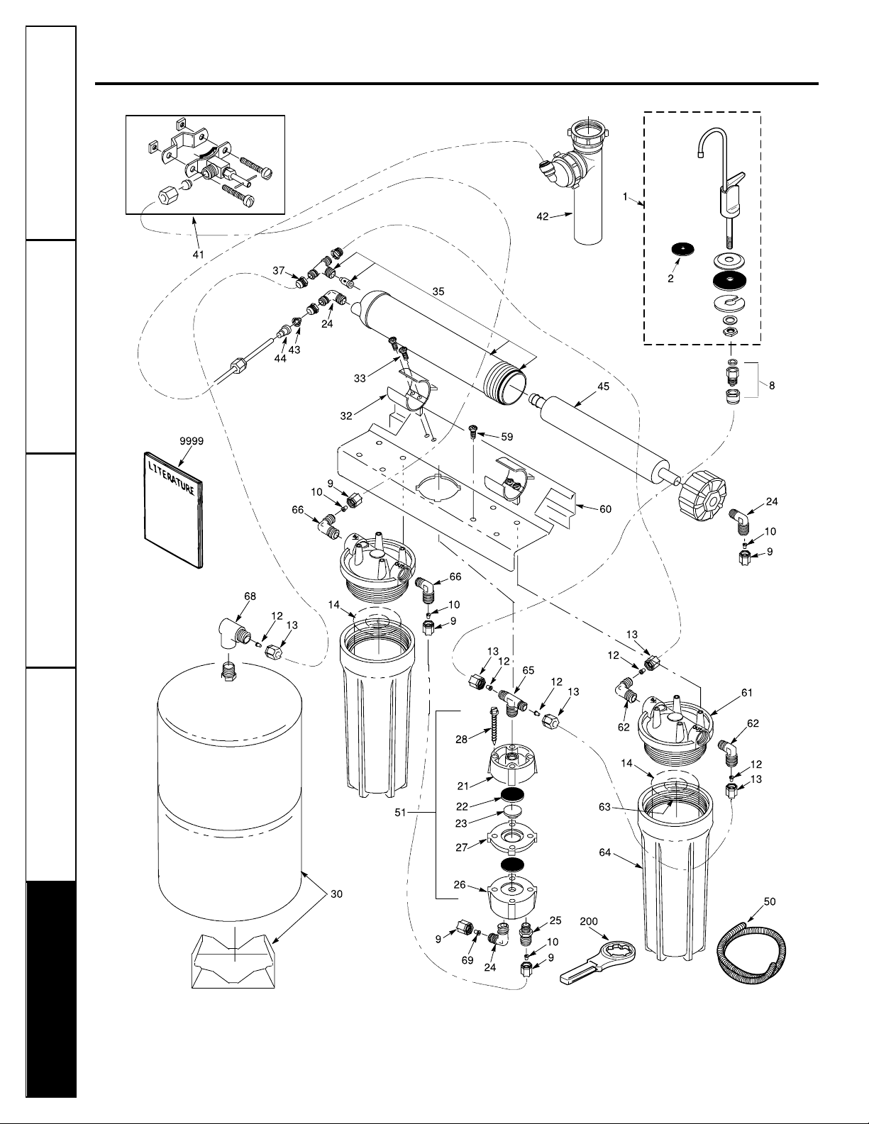
Parts list.
20
Consumer Support
Troubleshooting Tips Operating Instructions Safety InstructionsInstallation InstructionsInstallation Instructions
Page 21

Consumer SupportTroubleshooting TipsOperating InstructionsSafety Instructions Installation Instructions
21
General Electric parts catalog. www.GEAppliances.com
REF. NO. PART NO. PART DESCRIPTION GXRV10ABL01
0001 WS15X10024 FAUCET BLACK TIP & LEVER 1
0002 WS08X10002 GASKET TOP 1
0008 WS03X10003 ADAPTOR TUBING 1
0009 WS22X10005 NUT 1/4″ TUBE 8
0010 WS22X10006 INSERT 1/4″ TUBE 7
0012 WS22X10007 INSERT 3/8″ TUBE 7
0013 WS22X10008 NUT 3/8″ TUBE 7
0014 FX12P PRE & POST FILTERS 2
0021 WS10X10005 VALVE BOTTOM 1
0022 WS22X10009 DIAPHRAGM 2
0023 WS22X10010 PLUNGER 1
0024 WS22X10012 ELBOW 1/8″ NPT X 1/4″ 1
WS22X10011 ELBOW 1/8″ NPT X 1/4″ & NUT 3
0025 WS22X10013 CONNECTOR W/NUT 1/8″ NPT 1
0026 WS10X10006 VALVE TOP 1
0027 WS10X10007 VALVE CENTER 1
0028 WS02X10010 SCREW #10-14 X 1-3/4″ 4
0030 WS32X10012 TANK 1.3 GAL. 1
0032 WS02X10018 CLIP 2
0033 WS02X10017 SCREW 4
0035 WS35X10033 HOUSING & CHECK ASM 1
0041 WS15X10023 SADDLE VALVE–SUPPLY* 1
0042 WS18X10006 DRAIN LINE ADAPTER–DLA9 1
0043 WS03X10015 SCREEN CONE 1
0044 WS03X10042 CONTROL FLOW 1
0045 FX12M RO CARTRIDGE 1
0050 WS07X10008 TUBING 3/8″ X 20 FT–WH 1
WS07X10005 TUBING 1/4″ X 10 FT–BL 1
WS07X10007 TUBING 3/8″ X 20 FT–BL 1
WS07X10006 TUBING 1/4″ X 20 FT–WH 1
0051 WS15X10014 SHUTOFF ASSEMBLY 1
0059 WS02X10020 SCREW, #10 X 1/2″ 8
0060 WS28X10008 BRACKET 1
0061 WS19X10007 HEAD 2
0062 WS22X10002 ELBOW 3/8″ NPT X 3/8″ 2
0063 WS03X10001 O-RING 3-3/8″ X 3-5/8″ 2
0064 WS30X10001 SUMP 1
0065 WS22X10025 TEE 1/8″ NPT X 3/8″ TUBE 1
0066 WS22X10026 ELBOW 3/8″ NPT X 1/4″ TUBE 2
0068 WS22X10027 ELBOW, 1/4″ NPT X 3/8″ 1
0069 WS22X10028 INSERT, FLOW CONTROL 1
0200 WX5X140 WRENCH SUMP 1
9999 49-50071 OWNER’S MANUAL/INSTALLATION 1
INSTRUCTIONS
* NOTE: Codes in the State of Massachusetts require installation by a licensed plumber
and do not permit the use of the saddle valve. For installation, use plumbing code 248-CMR
of the Commonwealth of Massachusetts.
To obtain replacement parts, call toll-free 800-626-2002 (U.S.), 800-663-6060 (Canada–English),
800-361-3869 (Canada–French).
Page 22

22
Notes.
Consumer Support Troubleshooting Tips
Installation Instructions
Safety Instructions
Operating Instructions
Page 23

GE Reverse Osmosis System Warranty.
Consumer SupportTroubleshooting TipsOperating InstructionsSafety Instructions Installation Instructions
23
For The Period Of: GE Will Replace:
One Year Any part of the Reverse Osmosis Filtration System which fails due to a defect in materials or
From the date of the workmanship. During this limited one-year warranty, GE will also provide, free of charge, all labor
original purchase (does not include service trip to home) to replace the defective part. All warranty service will be
provided by a GE SmartWater™ Authorized Servicer.
All warranty service provided by our SmartWater™ Authorized
Servicer Network. To schedule service on-line, 24 hours a day,
contact us at www.GEAppliances.com, or call toll-free
800.GE.CARES (U.S.), or 866.777.7627 (Canada).
■ Service trips to your home to teach you how to use the
product.
■ Improper installation.
■ Failure of the product if it is abused, misused, or used
for other than the intended purpose.
■ Filters or membranes.
■ Defects that result from improper installation or damage
not caused by GE.
■ Liability on the part of GE under this or any other
warranty for any indirect or consequential damage.
■ Products that are used for commercial or industrial
applications.
■ Use of this product where water is microbiologically
unsafe or of unknown quality, without adequate
disinfection. Systems certified for cyst reduction may be
used on disinfected water that may contain filterable cysts.
■ Replacement of house fuses or resetting of circuit
breakers.
■ Damage to the product caused by accident, fire, floods or
acts of God.
■ Incidental or consequential damage caused by possible
defects with this appliance.
What GE Will Not Cover:
This warranty is extended to the original purchaser and any succeeding owner for products purchased for home
use within the USA. In Alaska, the warranty excludes the cost of shipping or service calls to your home.
Some states do not allow the exclusion or limitation of incidental or consequential damages. This warranty gives
you specific legal rights, and you may also have other rights which vary from state to state. To know what your
legal rights are, consult your local or state consumer affairs office or your state’s Attorney General.
THIS WARRANTY IS INTENDED TO BE IN LIEU OF ALL OTHER WARRANTIES, WHETHER EXPRESS OR IMPLIED,
INCLUDING THE WARRANTIES OF MERCHANTABILITY AND FITNESS FOR A PARTICULAR PURPOSE.
Warrantor: General Electric Company. Louisville, KY 40225
Staple your receipt here.
Proof of the original purchase
date is needed to obtain service
under the warranty.
Page 24

24
Service à la clientèle Conseils de dépannage
Fonctionnement Mesures de sécuritéInstallation
Mesures de sécurité . . . . . . . . . . . . . . . . .25
Fonctionnement
Au sujet du système de filtration par
osmose inversée . . . . . . . . . . . . . . . . . .27, 28
Guide des spécifications . . . . . . . . . . . . . .26
Entretien et nettoyage
Procédure de remplacement
de la cartouche du RO,
incluant la désinfection . . . . . . . .29–32, 41
Remplacement des cartouches . . . . . .29, 31
Instructions d’installation
Avant de commencer l’installation . . . . . .34
Instructions d’installation étape
par étape . . . . . . . . . . . . . . . . . . . . . . .35–41
Alimentation d’eau . . . . . . . . . . . . . . . .35
Installation de l’ensemble
du système . . . . . . . . . . . . . . . . . . . . . . .40
Installation du robinet . . . . . . . . . . . . . .38
Liste de vérifications . . . . . . . . . . . . . . . .41
Raccordements à la conduite
de vidange . . . . . . . . . . . . . . . . . . . .36, 37
Tuyaux pour le robinet de vidange
et pour l’alimentation d’eau . . . . . . . . .39
Outillage et matériel requis . . . . . . . . . . . .33
Recommandations importantes . . . . . . . .33
Conseils de dépannage . . . . . . . . . . . . . .42
Soutien au consommateur
Garantie . . . . . . . . . . . . . . . . . . . . . . . . . . .46
Liste des pièces/catalogue . . . . . . . . . .43, 44
Soutien au consommateur . . . . . . . . . . . .47
La section Française.
Numéro de modèle : __________________________
Numéro de série : ____________________________
Vous les trouverez sur le support du corps de filtre.
Le système GXRV10ABL a été
testé et homologué par NSF
International selon la norme
NSF/ANSI 58 pour les
caractéristiques spécifiées
dans la feuille de données
relatives à la performance.
Page 25

25
MESURES DE SÉCURITÉ IMPORTANTES.
LISEZ D’ABORD TOUTES LES INSTRUCTIONS.
www.GEAppliances.com
■ Vérifiez avec les travaux publics locaux ou de votre
état quels sont les codes régissant la plomberie et les
aménagements sanitaires. Vous devrez vous y conformer
lors de l’installation du système du système de filtration
par osmose inversée. Il est recommandé de faire appel à
un installateur qualifié.
■ Si la pression de l’eau arrivant à l’habitation dépasse
la valeur maximale de 125 livres/po2, montez un
détendeur dans la conduite d’arrivée de l’eau au
système de filtration.
■
Assurez-vous que l’eau est conforme au Guide des
spécifications. Si les conditions de l’eau ne sont pas
connues, contactez votre compagnie municipale de
fourniture d’eau ou votre service de santé local pour
obtenir une liste des agents de contamination de votre
région et une liste des laboratoires homologués par
votre état pour l’analyse de l’eau de table.
MISE EN GARDE : Avant la première utilisation
du système de filtration, celui-ci doit être purgé. La
cartouche du système de filtration par osmose inversée
contient un préservatif pour aliments qui doit être purgé
du système. Ce préservatif donne à l’eau un goût et une
odeur désagréables.
■ Cet appareil réduit la fluoration de l’eau de table.
Veuillez consulter votre dentiste pour toute question
à ce sujet.
MISE EN GARDE : N’utilisez pas l’appareil avec
de l’eau qui n’est pas sûre microbiologiquement ou de
qualité inconnue sans qu’elle n’ait été désinfectée
avant l’entrée ou la sortie de celui-ci. Les appareils
homologués pour la réduction des bactéries peuvent
être utilisés pour le filtrage de l’eau qui a été
désinfectée pouvant contenir des bactéries filtrables.
Cet appareil comporte une cartouche avec membrane
remplaçable essentielle pour réduire efficacement les
matières solides totalement dissolvables (TSD). Il est
nécessaire de tester l’eau périodiquement afin de
s’assurer que l’appareil fonctionne de manière
satisfaisante. Cet appareil est acceptable pour des
concentrations maximum de nitrates à 27 mg par litre
et de nitre à 3 mg par litre en combinaison appelée N.
Il est acceptable pour la réduction de nitrate/nitre dans
de l’eau dont la pression est égale ou supérieure à
280kPA (40psig).
■
Ce système ne sera utilisé pour réduire l’arsenic des
approvisionnements d’eau chlorées contenant du
chlore résiduel libre à l’entrée du système. Les systèmes
utilisant un injecteur de chlore en ligne doivent fournir
un contact d’une durée d’une minute avec le chlore
avant le système d’osmose inversée.
CONSERVEZ CES INSTRUCTIONS
VEUILLEZ LIRE ET SUIVRE ATTENTIVEMENT
CES MESURES DE SÉCURITÉ.
■ Installez l’appareil ou entreposez-le de telle façon qu’il
ne soit pas exposé à des températures inférieures au
point de congélation ou non à l’abri de tout type de
conditions météorologique. Il sera endommagé par
l’eau qui se congèle. N’essayez pas de traiter de l’eau
dont la température est supérieure à 100 degrés F.
■ Ne branchez pas l’appareil sur une conduite d’eau
bouillante. La température de l’eau arrivant au système
doit se trouver entre 40°F. au minimum et 100°F. au
maximum. Voyez le guide des spécifications.
■ N’ouvrez pas le robinet d’alimentation d’eau avant le
rinçage des conduites.
■ Période prologée de non-utilisation du système de filtration.
Si le système n’a pas été utilisé au cours d’une période
d’une semaine ou plus, ouvrez le robinet d’eau RO pour
permettre la vidange de celui-ci. Fermez le robinet pour
permettez au système de régénérer l’alimentation en eau.
MISE EN GARDE : Débarrassez-vous de tous les
composants non-utilisés ainsi que de l’emballage après
l’installation. Les petites pièces qui restent après
l’installation peuvent constituer un danger d’étouffement
si ingérées.
■
Désinfectez les éléments au cours de l’installation et
après l’entretien des composants internes. Ceci inclut le
remplacement de l’élément de pré-filtrage, l’élément
du post-filtrage et de la cartouche de l’appareil. Il est
important que les mains soient propres lors de la
manipulation des éléments internes du système.
Voyez la section Désinfection du système de filtration
par osmose inversée.
■
L’appareil comporte un élément de traitement
remplaçable pour réduire efficacement des matières
solides totalement dissolvables (TDS). Il sera
périodiquement testé pour s’assurer qu’il fonctionne
de manière satisfaisante. Voyez la section Au sujet de la
trousse de test de l’eau.
MISE EN GARDE!
Pour votre sécurité, suivez les instructions fournies dans le présent
manuel afin de minimiser les risques de dommages au matériel ou de
blessures corporelles.
PRÉCAUTIONS DE SÉCURITÉ
INSTALLATION ET ENTRETIEN DU SYSTÈME
Avant son utilisation, le système de filtration doit être correctement installé et positionné
conformément aux instructions d’installation.
Service à la clientèleConseils de dépannageFonctionnementMesures de sécurité Installation
Page 26

26
Service à la clientèle Conseils de dépannage
Fonctionnement Mesures de sécuritéInstallation
Guide des spécifications.
L’appareil produit une bonne quantité d’eau potable quotidiennement.
Cette quantité est fonction des données suivantes…
Produit – hauteur 40,64 cm (16 po) largeur 43,18 cm (17 po)
profondeur 15,24 cm (6 po)
Quantité maximale de fer, de manganèse, d’hydrogène sulfuré (en ppm) . . . . . . .<0,1
Chlore dans l’eau . . . . . . . . . . . . . . . . . . . . . . . . . . . . . . . . . . . . . . . . . . . . . . . . . . . . . .Autorisé
b
Limites pH de l’eau d’admission . . . . . . . . . . . . . . . . . . . . . . . . . . . . . . . . . . . . . . . . .4–10
Production d’eau (de qualité) en gallons par 24 heures . . . . . . . . . . . . . . . . . . . . . .38 L (10 gallons)
a
Eau traitée par gallon d’eau produite par 24 heures – gallons . . . . . . . . . . . . . . . .5
Pourcentage de rejet des TDS (nouvelle membrane) . . . . . . . . . . . . . . . . . . . . . . . .92
a
Pourcentage de réduction des bactéries . . . . . . . . . . . . . . . . . . . . . . . . . . . . . . . . . .99,95%
Capacité du réservoir – gallons . . . . . . . . . . . . . . . . . . . . . . . . . . . . . . . . . . . . . . . . . .1.3
Commande d’arrêt automatique . . . . . . . . . . . . . . . . . . . . . . . . . . . . . . . . . . . . . . . . . .yes
Pré-filtre et post-filtre . . . . . . . . . . . . . . . . . . . . . . . . . . . . . . . . . . . . . . . . . . . . . . . . .(FX12PA) Bloc de charbon
Membrane du système de filtration par osmose inversée . . . . . . . . . . . . . . . . . . . .(FX12M) Pellicule mince en
. . . . . . . . . . . . . . . . . . . . . . . . . . . . . . . . . . . . . . . . . . . . . . . . . . . . . . . . . . . . . . . . . . . . .Polyamide
Dimensions (en pouces) . . . . . . . . . . . . . . . . . . . . . . . . . . . . . . . . . . . . . . . . . . . . . . . .hauteur 40,64 cm (16 po)
largeur 43,18 cm (17 po)
profondeur 15,24 cm (6 po)
Limites de pression de l’eau à l’admission – livres par pouce carré (psi) . . . . . . . . . . . . . . . . . . . .40–125
c
Limites de température de l’eau à l’admission – min/max en degrés F . . . . . . . . . . . . . . . . . . . . . .40–100
Maximum de matières solides totalement dissolvables (TDS) – parties par millions (ppm) . . . .2000
Dureté maximale de l’eau @ 6.9 pH conseillé pour optimiser la vie de membrane –
grains par gallon (gpg) . . . . . . . . . . . . . . . . . . . . . . . . . . . . . . . . . . . . . . . . . . . . . . . . . . . . . . . . . . . . . . . .10
Lorsque la dureté de l’eau est supérieure à 10 grains (à un pH de 6,9),
il est recommandé d’utiliser un adoucisseur. Si un adoucisseur n’est
pas installé, la durée de vie de la membrane du système de filtration
par osmose inversée est réduite. Voyez le graphique pour les
informations complémentaires concernant la nécessité d’installer
un adoucisseur d’eau.
a. Lorsque testé par NSF International conformément à la norme 58 de l’ANSI/NS, la quantité était
de 7,1 GPD. Pour le test, les paramètres de l’eau d’origine sont de 50 psig, 77°F. un pH de 7,5 +à- 0,5
et une valeur ppm (parties par million) de 750 de matières solides totalement dissoutes.
b. Éliminé (maximum de 2,0 ppm) par le pré-filtre du système de filtration par osmose inversée.
UN ENTRETIEN RÉGULIER EST NÉCESSAIRE. Le chlore détruira la membrane du système de filtration
par osmose inversée.
c. Si la pression de l’eau arrivant à l’habitation dépasse 125 livres/po2, montez un détendeur dans la
conduite d’arrivée de l’eau au système de filtration. Si cette pression est inférieure à 40 livres/po2,
installez une pompe d’appoint sur l’appareil de filtration (contactez votre magasin de plomberie local).
8
7,5
7
6,5
pH de l’eau d’admission
6
Adoucisseur
d’eau inutile
DURETÉ DE L’EAU D’ADMISSION (GPG)
ADOUCISSEUR D’EAU RECOMMANDÉ
30
2010
40
50
60
Page 27

27
Description du système de filtration par osmose inversée
Pré-filtre—L’eau en provenance de la conduite d’eau
froide est dirigée dans la cartouche du pré-filtre se
trouvant à l’intérieur du corps de filtre. Le pré-filtre
est une cartouche de récupération des sédiments
remplaçable qui contient du charbon actif. Le pré-filtre
élimine le sable, le limon, les saletés et autres sédiments et
un maximum de 2,9 ppm de chlore présents dans l’eau.
Il réduit la quantité de chlore de l’eau, lequel DÉTRUIT LA
MEMBRANE DU SYSTÈME. L’eau propre, filtrée et à teneur
de chlore réduite s’écoule du pré-filtre vers la cartouche
du système.
Réservoir—Le réservoir contient jusqu’à 1,3 gallon d’eau
traitée. À l’intérieur, un diaphragme maintient l’eau sous
pression lorsque le réservoir est plein de façon à assurer
une débit rapide vers le robinet lorsque l’on désire avoir
de l’eau potable.
Clapet anti-retour—Un clapet anti-retour est monté à
une des extrémités du logement du système de filtration
par osmose inversée. Ce clapet empêche le refoulement
de l’eau traitée en provenance du réservoir. Un tel
refoulement pourrait entraîner la rupture de la
membrane du système.
Ensemble d’arrêt automatique—Dans le but de conserver
l’eau, le système de production d’eau potable comporte
un dispositif d’arrêt automatique. Lorsque le réservoir est
plein et que le robinet d’alimentation en eau potable est
fermé, la pression ferme l’appareil. Le débit d’eau vers le
logement du système de filtration par osmose inversée est
interrompu jusqu’à ce que l’eau potable soit à nouveau
utilisée et que la pression chute dans le système.
AVERTISSEMENT : Le système d’osmose inversée
contient un élément remplaçable essentiel à son
efficacité. On doit remplacer l’élément d’osmose
inversée par un élément ayant les mêmes
caractéristiques techniques, telles que définies par le
fabricant, pour assurer la même efficacité et le même
rendement de réduction des matières contaminants.
Au sujet du système de filtration par osmose inversée.
www.GEAppliances.com
Ce que ce système accomplit
Le système de filtration par osmose inversée élimine les
matières solides totalement dissoutes (TDS) ainsi que les
matières organiques de l’eau par diffusion au travers
d’une membrane spéciale. Cette membrane sépare les
matières minérales et les impuretés de l’eau, lesquelles
sont évacuées dans le tuyau de vidange. L’eau
de haute qualité produite est acheminée directement au
robinet d’alimentation en eau potable ou au réservoir.
L’appareil produit une bonne quantité d’eau potable
quotidiennement. Voir les Guide des spécifications cidessus. La quantité d’eau produite est fonction de
la pression d’eau d’alimentation, de sa température
et de sa qualité.
Les pré-filtre et post-filtre au charbon sont des cartouches
remplaçables. Le pré-filtre élimine le chlore et filtre les
sédiments. Le post-filtre élimine les goûts et les odeurs
indésirables avant l’utilisation de l’eau.
Corps de filtre
Corps de filtre
Cartouche du
post-filtre
Cartouche du pré-filtre
Bouchon de la conduite
d’admission
Cartouche du système de filtration
par osmose inversée
Logement du système de filtration
par osmose inversée
Tourner le corps de filtre dans
ce sens pour le démontage
Joint torique à l’intérieur
du corps de filtre
Ensemble d’arrêt
automatique
Extrémité du joint torique
Clapet du système
de filtration par
osmose inversée
Service à la clientèleConseils de dépannageFonctionnementMesures de sécurité Installation
Page 28

28
Au sujet du système de filtration par osmose inversée.
Cartouche du système de filtration par osmose
inversée—La cartouche qui se trouve à l’intérieur
du logement du système comprend une membrane
étroitement sertie. L’eau est forcée au travers de la
cartouche où la membrane élimine les matières
solides dissoutes et les matières organiques. L’eau
traitée de haute qualité sort du logement du
système et se dirige vers le réservoir. L’eau rejetée
contenant les matières solides dissoutes et les
déchets organiques quitte le logement puis est
déchargée à l’orifice de vidange au passant par la
conduite de 1/4 po.
Post-filtre—Après avoir quitté le réservoir mais
avant d’être acheminée au robinet du système,
l’eau produite s’écoule vers le post-filtre se
trouvant dans le corps de filtre. Le post-filtre est
aussi une cartouche de filtration des sédiments
remplaçable contenant du charbon actif. Tout
reliquat de goûts, d’odeur ou de sédiments sont
éliminés de l’eau par le post-filtre. L’eau potable
propre de haute qualité s’écoule par la conduite
vers le robinet du système.
Régulation de débit—Le régulateur de débit
contrôle le débit de l’eau au travers de la
cartouche du système de filtration pour obtenir
la valeur requise nécessaire à la production d’eau
de haute qualité. Il est situé sur le raccord en
coude localisé à l’orifice de vidange du logement
du système. Un petit tamis conique s’adapte
sur la partie avant du régulateur de débit pour
empêcher toute obturation causée par les
sédiments de l’eau de vidange. Le régulateur
doit être remplacé chaque fois que la membrane
du système de filtration par osmose inversée
est changée.
Service à la clientèle Conseils de dépannage
Fonctionnement Mesures de sécuritéInstallation
Tamis
Dispositif de régulation
de débit
Conduite de
1/4 po
Écrou de
compression
Raccord en T du
clapet anti-retour
Raccord en
coude de
vidange
Vers l’orifice
de vidange
Page 29

Assurez-vous de laver vos mains avec du savon
anti-bactéries avant de manipuler les éléments
internes du système.
Fermez le robinet d’alimentation du système
de filtration par osmose inversée. Ouvrez le
robinet RO et laissez le réservoir ouvert.
Permettez l’eau présente dans le système de
se vider complètement (cette opération dure
plusieurs minutes).
Si votre système de filtration est raccordé
au dispositif de fabrication de glace du
réfrigérateur, VOUS DEVEZ arrêter l’appareil
de fabrication de glace en soulevant la tige de
détection avant de travailler sur le filtre, avant
de remplacer les filtres ou avant de purger le
système. Quatre heures après l’entretien de
l’appareil, abaisser la tige de détection pour
remettre l’appareil de fabrication de glace
en marche.
Retirez le système de filtration de son placard
sans débrancher les conduites. Placez une
serviette sèche sous l’appareil pour absorber
l’eau qui coulera pendant le démontage.
Dévissez le couvercle de l’orifice d’admission
afin d’ouvrir le logement du système de
filtration à osmose inversée.
La désinfection du système est effectuée avec la
cartouche du système de filtration et les cartouches
de filtre démontées du système.
Démonter la cartouche du système de
filtration de son logement en tenant
l’extrémité de la cartouche à l’aide de
pinces propres et en tirant sur la droite.
NOTE : Il est possible que l’eau soit décolorée
lorsque la cartouche est démontée. Ceci est
NORMAL. Placez la cartouche dans un sac en
plastique propre pour la mettre à l’abri de tout
dommage jusqu’à ce que l’élément ait été remonté.
Remontez le bouchon de la conduite
d’admission en s’assurant que le joint torique
est en place.
Retirer le corps de filtre du POST-FILTRE
en le tournant vers la gauche à l’aide de la
clef pour corps de filtre fournie avec le
système. Faites attention lorsque vous
démonterez le corps de filtre étant donné
qu’il est rempli d’eau. Retirez la cartouche
usée du corps de filtre et jetez-la. Vérifiez le
corps de filtre. Assurez-vous que le joint
torique est bien place à la partie supérieure
du corps de filtre. Remontez le corps de
filtre (sans la cartouche) pour la
désinfection.
Retirez le corps de filtre du PRÉ-FILTRE à
l’aide de la clef pour corps de filtre et jetez
la cartouche usée. Assurez-vous que le joint
torique est bien place à la partie supérieure
du corps de filtre.
7
6
5
4
3
2
1
29
Entretien et nettoyage du système de filtration
par osmose inversée.
www.GEAppliances.com
Pour obtenir des filtres de replacement, composez sans frais le service des pièces détachées de GE au
800-626-2002 (États-Unis), au 800-663-6060 (Canada, langue anglaise), au 800-361-3869 (Canada, langue française).
ATTENTION : Avant d’effectuer l’entretien du système de filtration, fermez le robinet d’alimentation/
soupape à étrier et ouvrez le robinet d’eau RO. Permettez au système de se vider.
Cartouche de rechange du pré-filtre/post-filtre FX12P Bloc de charbon
Cartouche de rechange du système de filtration FX12M Pellicule mince en polyamide
Cartouche de rechange pour le pré-filtre et le post-filtre
Suivez les étapes de la section Désinfection du système de filtration par osmose inversée.
EXCEPTION : jeter les filtres usés et les remplacer avec des filtres neufs.
Trousse pour le test d’eau
Ce système de filtration par osmose inversée comporte un élément de traitement remplaçable
indispensable pour assurer une réduction efficace des matières solides totalement dissoutes (TDS).
Ce produit sera testé périodiquement pour s’assurer que le système fonctionne de manière
satisfaisante. Suivez les instructions incluses dans la trousse. L’eau produite doit être testée au
minimum tous les six mois. Une trousse de rechange vous sera fournie avec les résultats de chaque
test effectué.
Entretien et nettoyage—Procédure de remplacement de la cartouche
du RO, incluant la désinfection.
Service à la clientèleConseils de dépannageFonctionnementMesures de sécurité Installation
Page 30

Désinfectez le système.
ATTENTION : Avant l’ajout de produit désinfectant,
assurez-vous de bien retirer toutes les cartouches
comme indiqué ci-dessus. Le chlore détruira la
cartouche du système de filtration par osmose
inversée. La désinfection du système est effectuée
avec la cartouche du système et celles des filtres
retirées du système.
Avant de remonter le corps de filtre du
PRÉ-FILTRE, remplissez-le avec de l’eau froide
à environ 2,54 cm (1 po) du joint torique.
Ajoutez une once (35 ml deux cuillères à café)
d’Eau de Javel ordinaire concentrée à 5,25%
(Hilex, Clorox, etc) et la mélangez à l’eau.
N’AJOUTEZ PAS LE CHLORE (EAU DE JAVEL) EN
PREMIER. Le chlore concentré peut endommager
le plastique.
Remontez le corps de filtre avec soin sur le
système de filtration par osmose inversée et le
serrez à la main de façon sûre.
Fermez le robinet d’eau RO et ouvrez le robinet
d’alimentation d’eau au système. Permettez au
système de se remplir pendant une minute.
NOTE : Au cours de la désinfection, de multiples sons
se feront entendre. N’UTILISEZ PAS L’EAU AU COURS
DE CETTE OPÉRATION.
Ouvrez le robinet d’eau RO et verrouillez le
levier vers le haut contre le bec. Permettez à
l’eau de s’écouler à travers du système de
filtration par osmose inversée jusqu’à ce que
toute odeur d’Eau de Javel a disparu (après
20 minutes environ).
Fermez le robinet d’alimentation d’eau du système
mais laissez le robinet RO ouvert. Une fois que le
débit d’eau s’est arrêté, passez à l’étape 9.
Assurez-vous de vous être lavé les mains avec le savon
anti-bactéries. Répétez les opérations des étapes 3–6
et 8b; cependant, remontez la cartouche du système
de filtration placé dans le sac en plastique ainsi que
les nouveaux PRÉ-FILTRE et le POST-FILTRE au lieu
de les enlever. Mettez une légère couche de graisse
sur le couvercle de la conduite d’admission
et sur les joints toriques du corps de filtre. Utilisez
uniquement que de la graisse au silicone.
NOTE : La cartouche du système de filtration comporte
une encoche et il peut être nécessaire de la tourner au
cours du remontage pour qu’elle soit correctement mise
en place.
Ouvrez le robinet d’alimentation du système de
filtration par osmose inversée et allouez environ
quatre heures pour la régénération et la stabilisation
du système. Vérifiez qu’il n’y a pas de fuites. Le
système peut émettre des sons au cours de cette
période. Ceci est normal.
Remplacez les piles alcalines “AA” se trouvant dans
le boîtier de commande. Il est nécessaire de disposer
de piles en bon état pour assurer le fonctionnement
correct du voyant indicateur. Des piles faibles peuvent
donner une indication erronée. Ces piles doivent être
remplacées tous les six mois.
Avant la première utilisation consécutive à un
changement de filtre, purgez le système en ouvrant
le robinet d’eau RO pendant une minute afin
d’éliminer tout dépôt de particules de charbon.
Si le système est raccordé au dispositif de fabrication
de glace de votre réfrigérateur, replacez la tige de
détection du dispositif sur la position On (marche)
(vers le bas) après la période de régénération de
quatre heures.
12
11
10
9
e
d
c
b
a
8
Desserrez
Clef pour
corps
de filtre
Entretien et nettoyage—Procédure de remplacement de la cartouche
du RO, incluant la désinfection.
Corps de filtre
Corps de filtre
Cartouche du
post-filtre
Cartouche du
pré-filtre
Bouchon de la conduite
d’admission
Cartouche du système de
filtration par osmose inversée
Logement du système de filtration
par osmose inversée
Tourner le corps de filtre dans
ce sens pour le démontage
Joint torique à
l’intérieur du
corps de filtre
Ensemble d’arrêt
automatique
Extrémité du joint torique
Clapet du système de filtration
par osmose inversée
Service à la clientèle Conseils de dépannage
Fonctionnement Mesures de sécuritéInstallation
30
Page 31

NOTE : Lors du remplacement de la cartouche du
système de filtration par osmose inversée, montez
aussi un régulateur de débit et un tamis. Voyez la
section Régulation de débit et tamis.
Si votre système de filtration est raccordé au
dispositif de fabrication de glace du réfrigérateur,
VOUS DEVEZ arrêter l’appareil de fabrication de
glace en soulevant la tige de détection avant de
travailler sur le filtre, avant de remplacer les filtres
ou avant de purger le système. Quatre heures
après l’entretien de l’appareil, abaisser la tige de
détection pour remettre l’appareil de fabrication
de glace en marche.
Assurez-vous de vous être lavé les mains avec du
savon anti-bactéries avant de manipuler les
éléments internes du système.
Fermez le robinet d’alimentation d’eau au
système de filtration (dans le sens horaire)
et ouvrez le robinet d’eau RO. Permettez au
système de se vider complètement (ceci
nécessite plusieurs minutes).
ATTENTION :La non-fermeture du robinet
d’alimentation d’eau entraînera le giclage de
l’eau ou son écoulement lorsque les corps de
filtres sont démontés.
Retirez le système de filtration de son placard
et laissez les conduites branchées. Placez une
serviette sèche sous l’appareil.
Dévissez le couvercle de l’orifice d’admission
afin d’ouvrir le logement du système de
filtration à osmose inversée.
À l’aide de pinces, retirez la cartouche du
logement et jetez celle-ci.
Désinfectez le système.Voyez la Procédure
de remplacement du filtre, incluant la section
traitant de la désinfection. Effectuez les étapes
5–9. Cependant, placez les filtres dans des
sacs en plastique propres. Remontez-les à
l’étape 9.
5
4
3
2
1
Remplacement de la cartouche du système de filtration par osmose inversée
31
www.GEAppliances.com
Service à la clientèleConseils de dépannageFonctionnementMesures de sécurité Installation
Tamis
Dispositif de
régulation de débit
Conduite de
1/4 po
Écrou de
compression
Raccord en T du
clapet anti-retour
Raccord en
coude de
vidange
Vers l’orifice
de vidange
Page 32

32
Montez un nouveau régulateur de débit et
un tamis.
Montez le coude de la conduite de
vidange à proximité du raccord en
T du clapet anti-retour en laiton.
Dévissez l’écrou de compression.
Retirez le régulateur de débit avec une
lame de couteau propre. Retirez le tamis;
il est possible qu’un cure-dent soit
nécessaire.
Si vous remplacez le régulateur de débit
et le tamis, jetez-les. Si vous vérifiez le
régulateur de débit, le tamis et le tuyau
pour savoir s’il y a obturation, nettoyez ces
pièces pour vous débarrasser des débris.
Ne soufflez pas dans le régulateur de débit
pour ne pas contaminer l’élément.
Remplacez le tamis en plaçant l’extrémité
du cône dans le couvercle du coude et le
pousser à l’intérieur avec précaution.
ATTENTION
: Si vous sentez de la résistance,
ne forcez pas. Vérifiez visuellement qu’il a été
mis en place correctement.
Montez le régulateur de débit et serrez le
joint de compression à la main et donnez
un autre 1/4 de tour avec les pinces.
NE SERREZ PAS EXCESSIVEMENT, CE QUI
ÉCRASERAIT LA CONDUITE ET LE
RÉGULATEUR DE DÉBIT.
Dévissez le couvercle de l’orifice d’admission
afin de le retirer.
Montez la nouvelle cartouche du système
par osmose inversée.
NOTE : L’extrémité du joint torique de la cartouche
comporte une encoche et il peut être nécessaire
de le tourner au cours du remontage pour qu’il
s’emboîte correctement.
Graissez légèrement le joint torique en
utilisant exclusivement de la graisse au
silicone propre.
Remettez en place le couvercle de l’orifice
d’admission.
Faites couler l’eau et vérifiez s’il y a des fuites.
Purgez le système de filtration.
Ouvrez le robinet d’eau RO jusqu’à ce
que le réservoir soit vide et que le débit
d’eau s’arrête.
Après avoir rempli et vidé le réservoir
quatre fois, le système est prêt à fournir
de l’eau pour votre utilisation.
ATTENTION : La cartouche du système de
filtration par osmose inversée contient un
préservatif pour aliments qui doit être purgé
du système avant la première utilisation
ou lorsque la cartouche est remplacée.
Le préservatif donnera à l’eau produite
un goût et une odeur désagréables.
Remettez l’appareil de fabrication de glace en
marche en abaissant la tige de détection.
13
b
a
12
11
10
9
8
7
f
e
d
c
b
a
6
Entretien et nettoyage—Procédure de remplacement de la cartouche
du RO, incluant la désinfection.
Service à la clientèle Conseils de dépannage
Fonctionnement Mesures de sécuritéInstallation
Page 33

• Perceuse sans fil alimentée par batterie
• Mèche de perceuse de 1/4 po
• Mèche de perceuse de 1-1/4 po (du type nécessaire) si le montage est requis pour le robinet
• Clefs à molette réglables
• Tournevis normaux et Phillips
• Couteau
• Liste des composants de l’appareil :
—Ensemble de filtration par osmose inversée
—Imprimés concernant l’appareil (manuel d’utilisation et d’installation, vidéo sur l’utilisation et l’entretien,
fiche de performances et carte d’enregistrement à remplir par le propriétaire)
—Sac contenant les éléments des robinets d’alimentation
—Adaptateur de la conduite de vidange
—Conduite (longueur 68,6 cm [27 po], diamètre 3/8 po)
—Réservoir
—Étiquettes de rappel pour le remplacement des filtres
—Trousse de test de l’eau
RESPONSABILITÉ DE L’INSTALLATEUR : Le robinet d’alimentation d’eau (voyez la section Alimentation
de l’eau) est inclus pour être utilisé dans les zones autorisées par les codes. L’installateur doit se conformer
aux codes locaux ou ceux de l’état. S’il n’est pas en mesure de le faire, il doit fournir les raccords permettant
de prélever l’eau de la conduite d’eau froide pour alimenter le système de filtration par osmose inversée
(les raccords doivent s’adapter à une conduite OD de 1/4 po de diamètre).
Instructions d’installation.
33
Recommandations d’installation importantes
Lisez le manuel au complet. Le non-respect des guides et des règles à suivre pourrait entraîner des blessures
corporelles ou des dommages à la propriété.
• ASSUREZ-VOUS DE RESPECTER TOUS LES CODES LOCAUX OU DE L’ÉTAT QUI SONT APPLICABLES.
• Faites appel à un installateur qualifié.
• Ne montez pas le système de filtration par osmose inversée à l’extérieur ou à un endroit soumis à des
extrêmes de températures (chaud ou froid). NE FAITES PAS L’INSTALLATION SUR UNE CONDUITE
D’EAU BOUILLANTE.
• L’installation recommandée de l’appareil est sous l’évier. Cependant, il est possible de l’installer à un
endroit éloigné jusqu’à une distance de 30 pi de l’évier. Il peut être nécessaire de se procurer du matériel
complémentaire dans ce cas.
• Si le système de filtration est raccordé à l’appareil de fabrication de glace d’un réfrigérateur, une trousse
d’installation spéciale est nécessaire (RVKIT). N’utilisez pas des conduites en cuivre pour effectuer le
raccord entre le réfrigérateur et l’appareil.
• Assurez-vous que les spécifications de l’eau sont conformes aux valeurs communiquées; voyez la section
Guide des spécifications. Si les spécifications de l’eau sont inconnues, contactez votre fournisseur municipal
d’eau ou votre service de santé local pour vous procurer une liste des contaminants de votre zone d’habitation
et une liste des laboratoires homologués par votre état qui sont en mesure d’analyser l’eau potable.
MISE EN GARDE : N’utilisez pas l’appareil avec de l’eau qui n’est pas sûre microbiologiquement ou de qualité
inconnue sans qu’elle n’ait été désinfectée avant l’entrée ou la sortie de celui-ci. Les appareils homologués pour
la réduction des bactéries peuvent être utilisés pour le filtrage de l’eau qui a été désinfectée pouvant contenir
des bactéries flltrables. Le système ne sera utilisé que pour la réduction d’arsenic dans des eaux contenant du
chlore sans résidus à l’orifice d’admission de l’appareil. Les systèmes d’alimentation d’eau utilisant un dispositif
de chloration en ligne doivent être en mesure d’assurer un “temps de contact du chlore de une minute” avant
le système RO. Cet appareil comporte une cartouche avec membrane remplaçable essentielle pour réduire
efficacement les matières solides totalement dissolvables (TSD). Il est nécessaire de tester l’eau périodiquement
afin de s’assurer que l’appareil fonctionne de manière satisfaisante. L’appareil est acceptable pour des
concentrations maximum de nitrates à 27 mg par litre et de nitre à 3 mg par litre en combinaison appelée N. Il est
certifié pour la réduction de nitrate/nitre dans de l’eau dont la pression est égale ou supérieure à 280kPA (40psig).
Les composants de petite taille demeurant après l’installation peuvent présenter un danger d’étouffement si ingérés.
Débarrassez-vous en.
Outillage et matériel requis pour l’installation
Service à la clientèleConseils de dépannageFonctionnementMesures de sécurité Installation
Page 34

34
Instructions d’installation.
Points à vérifier avant de commencer l’installation
EAU D’ALIMENTATION—L’eau alimentant le système de
filtration par osmose inversée monté sous le comptoir
doit présenter des qualités répertoriées dans les
spécifications (voyez la section Guide des spécifications).
Dans la plupart des cas, l’eau fournie par les
municipalités répond à ces spécifications. L’eau de
puits peut requérir un traitement—Faites-la tester par un
laboratoire d’analyses et suivez leurs recommandations
pour traitement.
ATTENTION: Lorsque la dureté de l’eau est supérieure
à 10 grains (à un pH de 6,9), il est recommandé d’utiliser
un adoucisseur. Si un adoucisseur n’est pas utilisé, la
durée de vie de la membrane du système de filtration
sera réduite. Voyez la section Guide des spécifications
pour les informations complémentaires concernant la
nécessité de disposer d’un adoucisseur.
POINT DE VIDANGE*—L’eau évacuée provenant de la
membrane du système de filtration nécessite un point
de vidange approprié et un espace d’air (vérifiez vos
codes locaux) .
ROBINET RO—Le robinet d’eau produite RO est monté sur
l’évier ou sur le comptoir à proximité de l’évier. Souvent,
il est monté dans l’orifice de l’arrosoir existant. Il est
nécessaire de disposer d’un espace suffisant sous l’évier
ou le comptoir pour la conduite reliée au robinet ou en
provenance de celui-ci et pour le montage du robinet.
Tous les raccordements de robinet, conformément aux
méthodes de montage, sont effectués sur ou au dessus de
l’évier ou du comptoir. Voyez la figure 1 ci-dessous.
INSTALLATION DANS UN SOUS-SOL—Si l’installation est
effectuée dans un sous-sol, ménagez une longueur de
conduite suffisante au cours de l’installation afin de
faciliter l’entretien et d’assurer le remplacement des
filtres/membrane.
Fig. 1. APERÇU DE
L’INSTALLATION
Clef pour corps
de filtre fournie
Robinet RO d’eau produite
passant au travers de l’évier
Conduite de
vidange de
3/8 po
Soupape pour
l’alimentation
d’eau ou raccord
de compression
Eau
chaude
Collecteur-p
de l’evier
Tuyau de
vidange*
15,88 cm
(6-1/4 po)
38,1 cm
15 po
40,64 cm
16 po
22,86 cm
9 po dia.
43,18 cm
17 po
Profondeur
14 cm
5-1⁄ 2 po
Système de filtration par
osmose inversée
Réservoir
*Pour les options de montage du tuyau de vidange, voyez la section
Installations du raccordement de vidange du système de filtration.
Service à la clientèle Conseils de dépannage
Fonctionnement Mesures de sécuritéInstallation
Eau
froide
Page 35

Instructions d’installation étape par étape.
Alimentation d’eau
Vérifiez et conformez-vous aux codes de plomberie lors de la planification puis installez un raccord
d’alimentation d’eau froide. Pour les installations effectuées dans des nouvelles habitations utilisant
les raccords de plomberie standards, examinez d’abord les deux schémas ci-dessous. Une installation
type pour les habitations existantes utilisant la soupape à étrier est illustrée sur le troisième schéma
ci-dessous.
A. INSTALLATION PRÉFÉRENTIELLE
Fermez l’arrivée d’eau froide.
Pour respecter les codes de plomberie, montez un raccord sur le tuyau d’eau froide pour y
adapter un tube de 3/8 po OD. Un raccord type est illustré sur le schéma de droite (pièces non
incluses). Assurez-vous qu’un robinet d’alimentation est fourni.
2
1
B. INSTALLATION OPTIONNELLE EFFECTUÉE DANS UN DOMICILE Lorsque les codes l’autorisent
*Pour OD de 1/2 po ou tube métallique de plus grandes dimensions.
NOTE : Les codes de l’état du Massachusetts exigent que l’installation soit effectuée par un plombier
certifié et ne permettent pas l’utilisation de soupapes à étrier. Pour l’installation, utilisez le code 248-CMR
du Commonwealth du Massachusetts.
Fermez l’arrivée d’eau froide et montez la soupape à étrier comme illustré à droite.
DANGER : Pour vous mettre à l’abri de blessures graves ou de choc électrique fatal, utilisez une
perceuse alimentée par batterie pour faire le trou. N’UTILISEZ PAS DE PERCEUSE ÉLECTRIQUE.
Fermez le robinet d’alimentation d’eau en tournant la commande dans le sens horaire.
Ouvrez le robinet principal d’alimentation
et plusieurs autres robinets de l’habitation afin
de purger l’air du système. Fermez les robinets
une fois que l’écoulement d’eau est régulier.
3
2
1
Raccordement optionnel à la source d’alimentation d’eau
(avec utilisation de la soupape à bride)*
Trou de 1/4 po
pré-percé
Joint—assurez-vous que
le joint est en place
Bride X
Écrou (2)–Non
nécessaire si les
trous de la bride
sont filetés
Soupage
Poignée
Adaptateur de la conduite
Rondelle
Écrou de compression
Bride Z
Raccord préférentiel d’alimentation
d’eau (utilisant un raccord à
compression)
Raccord (non inclus)
Tuyau
d’eau
froide
Tube de raccordement à
la conduite d’admission
3/8 po
Bague d’extrémité
Robinet
d’alimentation d’eau
Localisation type
Eau
froide
Utilisez pour raccorder
la conduite
*Pour OD de 1/2 po ou tube métallique de plus
grandes dimensions.
Montez la soupape
dans le support
NE SERREZ PAS
EXCESSIVEMENT
Plusieurs filets
doivent être visibles
Joint en caoutchouc
35
Service à la clientèleConseils de dépannageFonctionnement
Mesures de sécurité
Installation
Fig. 2A.
Fig. 2B.
Page 36

36
Instructions d’installation étape par étape.
Raccordements à la conduite de vidange
Vérifiez et conformez-vous aux codes de plomberie lors de la planification.
ATTENTION : Les options décrites ci-dessous représentent UNIQUEMENT les configurations d’installation
homologuées. N’utilisez pas de systèmes comportant des soupapes à étrier.
NOTE : Le non-respect de ces instructions d’installation annulera la garantie. L’installateur est responsable de toute
intervention pour le service, des réparations ou des dommages causés par ce non-respect.
Fig. 3A.
Fig. 3B.
Fig. 3C.
En provenance du
second évier ou
compacteur
En provenance du second
évier ou compacteur
En provenance du
second évier ou
compacteur
En provenance
de l’espace d’air
du robinet
Conduite de vidange
du système de
filtration par osmose
inversée en dérivation
de l’espace d’air
Maintenez l’espace
d’air au point de
vidange dans le
sous-sol
Adaptateur de la
conduite de vidange
Clapet-p distinct
Bouchon
(non inclus)
Mín. 10,16 cm
4 po
En provenance
de l’espace d’air
du robinet
Adaptateur de la
conduite de vidange
Options d’installation préférentielles (Options A, B et C)
OPTION A.
INSTALLATION DU SYSTÈME AU SOUS-SOL (Fig. 3A)
Acheminez DIRECTEMENT la conduite de vidange du système de
filtration par osmose inversée à un évent du sous-sol, en dérivant
l’espace d’air ménagé dans le robinet. Il est aussi possible de diriger la
conduite de vidange sur un orifice d’évacuation du sol ou encore dans
une baignoire sous réserve que l’espace d’air du sous-sol est respecté.
Évitez de faire des boucles et autres formes non rectilignes avec la
conduite. L’espace d’air dans le sous-sol et la configuration de
l’installation de vidange doivent être conformes à tous les codes
locaux. Des raccords spéciaux pour l’espace d’air sont disponibles
pour le raccordement de la conduite à l’évent.
OPTION B.
INSTALLATION DISTINCTE DE L’ÉVENT—CLAPET-2P
(MISE À L’AIR LIBRE DU TYPE SEC) (Fig. 3B)
Installez un clapet-p de mise à l’air libre du type sec sous l’évier, lequel
sera utilisé exclusivement pour la conduite de vidange du système de
filtration par osmose inversée. Un clapet-p de mise à l’air libre du type
sec est un clapet-p comportant son propre dispositif de mise à l’air
libre/évent. Raccordez l’adaptateur de conduite fourni avec le système
au clapet-p et fixez-le à l’aide de l’écrou pour joint coulissant et la
rondelle comme indiqué sur le schéma. Acheminez la conduite de
vidange de l’espace d’air à l’adaptateur de la conduite en vous
assurant qu’elle est rectiligne et ne comporte pas de boucles qui
pourraient causer un bouchage de la conduite. L’adaptateur de la
conduite doit être aligné verticalement de telle façon que le
branchement du tuyau soit à 45° par rapport à la verticale (voyez la
figure 3E.). La conduite de vidange doit passer au travers de l’espace
d’air ménagé dans le robinet d’eau RO.
OPTION C.
INSTALLATION AVEC ÉVENT PARTAGÉ—CLAPET-2P
(MISE À L’AIR LIBRE DU TYPE HUMIDE (Fig. 3C)
Installez un clapet-p de mise à l’air libre du type humide sous l’évier,
lequel sera utilisé exclusivement pour la conduite de vidange du
système de filtration par osmose inversée. Un clapet-p de mise à l’air
libre du type humide est un clapet-p qui partage un dispositif de mise
à l’air libre/évent. Raccordez l’adaptateur de conduite fourni avec le
système au clapet-p et fixez-le à l’aide de l’écrou pour joint coulissant
et la rondelle comme indiqué sur le schéma. Acheminez la conduite
de vidange de l’espace d’air à l’adaptateur de la conduite en vous
assurant qu’elle est rectiligne et ne comporte pas de boucles qui
pourraient causer un bouchage de la conduite. L’adaptateur de la
conduite doit être aligné verticalement de telle façon que le
branchement du tuyau soit à 45° par rapport à la verticale (voyez la
figure 3E.). La conduite de vidange doit passer au travers de l’espace
d’air ménagé dans le robinet d’eau RO. Montez le clapet-p aussi haut
que possible (minimum de 4 po au dessus du tuyau horizontal du
second évier ou compacteur).
Bouchon
(non inclus)
Service à la clientèle Conseils de dépannage
Fonctionnement Mesures de sécuritéInstallation
Page 37

Raccordements à la conduite de vidange
Recommandation secondaire
(Utilisez uniquement s’il n’est pas possible
d’appliquer les options A, B ou C de la page 13).
OPTION D.
INSTALLATION DE L’ADAPTATEUR DE LA
CONDUITE DE VIDANGE (Fig. 3D)
N’INSTALLEZ PAS la conduite de vidange en aval d’un
compacteur ou dans un tuyau horizontal. Installez l’adaptateur
pour conduite de vidange qui est fourni sous l’évier comme
illustré. La chicane en T ou le raccord en Y indiqué doit être
en place (si nécessaire, achetez-en un et installez-le) pour
empêcher le bouchage de la conduite. Acheminez la conduite
de vidange de l’espace d’air à l’adaptateur de la conduite en
s’assurant qu’elle est rectiligne et ne comporte pas de boucles
qui pourraient causer un bouchage de la conduite. L’adaptateur
de la conduite doit être aligné verticalement de telle façon que
le branchement du tuyau soit à 45 degrés par rapport à la
verticale (voyez la figure 3E.). Cette installation PEUT causer
un petit bruit dans la conduite de l’évier lorsque le système de
filtration par osmose inversée fonctionne. Tournez l’ensemble
de l’adaptateur en T lentement jusqu’à ce que le bruit est réduit
au minimum. En général, une rotation de 180° par rapport au
tuyau horizontal/chicane en T est une bonne solution.
ATTENTION!
N’INSTALLEZ PAS L’ADAPTATEUR DE LA CONDUITE DE
VIDANGE EN AVAL DU COMPACTEUR.
Une fois installé, le tuyau ne doit comporter aucun tortillement,
boucle, etc. Il doit être coupé à la dimension appropriée pour
assurer une jonction rectiligne entre le robinet et l’orifice
de vidange (Fig. 3F.). Voyez les instructions à la section
Raccordements à la conduite de vidange pour les détails et options.
UNE INSTALLATION DÉFECTUEUSE ENTRAINERA LE
REFOULEMENT DE L’EAU DANS LA CONDUITE DE VIDANGE
ET CETTE EAU FUIRA AU ROBINET!
Fig. 3D.
Fig. 3E.
Chicane en T ou raccord-y
obligatoire
En provenance du
second évier ou
compacteur
45°
En provenance de l’espace
d’air du robinet
Adaptateur de la
conduite de vidange
Le raccord de la conduite de vidange
doit être orienté à 180° par rapport
au tuyau horizontal/chicane en T
existant tel qu’indiqué sur le schéma.
Adaptateur de la
conduite de vidange
Orientation correcte de l’adaptateur
de la conduite de vidange.
37
Fig. 3F.
Adaptateur de la conduite de vidange
La conduite
de vidange
est rectiligne
Adaptateur de la
conduite de vidange
dans une différente
conduite à partir du
compacteur
Compacteur
EAU
CHAUDE
EAU
FROIDE
Service à la clientèleConseils de dépannageFonctionnementMesures de sécurité Installation
Page 38

38
Fig. 4A.
Entretoise
Plaque de
montage
Base
Écrou hex
Levier
Bec
Tige du
robinet
Joint de grande
dimension
Écrou de
compression
Rondelle
métallique
Adaptateur
de tuya
ASSEMBLÉ
Instructions d’installation étape par étape.
Installation du robinet
Assurez-vous que vous disposez d’un espace suffisant sous
l’évier pour faire les raccordements. Choisissez l’un des
endroits suivants pour l’installation du robinet :
—PRISE du tuyau de pulvérisation d’eau ou du distributeur
de savon liquide de l’évier.
—ORIFICE devant être percé sur la partie supérieure de
l’évier.
—ORIFICE devant être percé sur la partie supérieure du
comptoir
NOTE : En vous basant sur le schéma de la Fig. 4B, assurez-vous
que la base du robinet s’adaptera sur la surface de la position
sélectionnée pour assurer une bonne jonction du robinet et
de la surface.
Si un perçage est nécessaire, faites un trou de 1-1/4 po
de diamètre. Assurez-vous que vous suivez la bonne
procédure pour le perçage de la porcelaine ou de l’acier
inoxydable.
Positionnez la base du robinet sur la tige filetée (collet
faisant face vers le bas). Ensuite, placez le grand joint
sur la tige filetée en vous assurant que la tige et les deux
tenons s’adaptent au travers du joint. Placez l’entretoise
sur la tige (extrémité ouverte vers le haut) suivie de la
rondelle métallique et de l’écrou hex (Fig. 4A ).
Insérez la rondelle dans l’adaptateur du tuyau. Serrez de
manière sécuritaire sur la tige du robinet.
Prenez le tuyau de 68,6 cm (27 po) de longueur et
de 3/8 po de diamètre. Poussez complètement l’une
des extrémités dans le raccord du robinet dont le
diamètre est de 3/8 po (Fig. 4B).
Positionnez le système de filtration sous l’évier. En vous
référant à la figure 5 de la page suivante, suspendez
l’appareil sur la paroi du placard.
Acheminez le tuyau de 1/4 po de diamètre (identifié
“1/4 po BARBON FAUCET”) et le tuyau de 3/8 po de
diamètre (identifié “FAUCET”) vers le haut au travers
du trou de montage :
Poussez une extrémité du tuyau de 1/4 po dans le
raccord à colonnes du robinet.
À l’aide de l’écrou de compression, fixez le tuyau de
3/8 po au raccord à l’adaptateur et serrez l’écrou.
Assurez-vous que le tuyau est parfaitement monté
sur l’adaptateur.
Retirez le tuyau ayant servi à l’expédition de l’appareil et
insérez le bec dans le corps du robinet.
Abaissez l’ensemble du robinet au travers de l’évier.
Sous le comptoir, placez la plaque de montage au dessus
de l’entretoise et serrez correctement l’écrou hex.
9
8
7
b
a
6
5
4
3
2
1
Fig. 4B.
Robinet
NOTE : Pour faciliter les opérations
d’entretien, gardez les tuyaux suffisamment
longs de telle façon que le retrait du
système de filtration par osmose inversée
situé sous le comptoir demeure possible.
Adaptateur de tuyau
Rondelle en
plastique
Raccord à colonne
de 1/4 po
Tuyau de 68,6 cm
(27 po) de longueur
et 3/8 po de diamètre
Raccord à colonnes
de 3/8 po
Tuyau de 3/8 po de diamètre
marqué FAUCET
Tuyau de 1/4 po de diamètre
marqué 1/4 po barb
Écrou de compression
Vers l’orifice
de vidange
En provenance
de RO
En provenance de RO
Service à la clientèle Conseils de dépannage
Fonctionnement Mesures de sécuritéInstallation
Page 39

Tuyaux pour la vidange et l’alimentation d’eau
Si l’option A, INSTALLATION DU SYSTÈME AU
SOUS-SO La été utilisée, passez à l’étape 2 (référez-vous
à la section Raccordement à la conduite de vidange).
Si l’option B, C ou D de la page 36 ou 37 a été utilisée,
raccordez le tuyau de vidange du robinet en reliant le
tuyau de 68,6 cm (27 po) de longueur et de 3/8 po de
diamètre au raccord à colonnes du robinet et au raccord
de l’orifice de vidange (installé à la section Raccordement à
la conduite de vidange). Assurez-vous que le tuyau est aussi
court et rectiligne que possible. Coupez le tuyau selon les
besoins et insérez-le dans le raccord de l’orifice de vidange
(référez-vous à la Fig. 3B, 3C ou 3D de la section
Raccordement à la conduite de vidange).
Pour raccorder le tuyau d’alimentation d’eau : Relier le
tuyau de 1/4 po (marqué “WATER SUPPLY”) au raccord
d’admission du système de filtration et au raccord
d’alimentation d’eau (voyez la Fig. 2A ou 2B, dans la
section Alimentation d’eau) et serrez l’écrou de manière
sécuritaire (utilisez un ruban de Teflon
TM
pour prévenir
toute fuite).
Apposez l’étiquette de rappel de remplacement de filtre
sur l’un des corps de filtre entre les nervures. Inscrivez la
date de remplacement du filtre six mois à partir de la date
d’installation.
3
2
1
39
Fig. 5.
Tuyau de vidange
de 3/8 po
Conduite
de
vidange*
Soupape pour
l’alimentation d’eau ou
raccord de compression
Eau
chaude
Ensemble d’arrêt automatique
Réservoir
* Pour les options de la conduite de vidange, référez-vous
à la section Raccordement à la conduite de vidange.
Admission RO
Étiquette de rappel de
remplacement de filtre
Service à la clientèleConseils de dépannageFonctionnementMesures de sécurité Installation
Eau
froide
Page 40

40
Instructions d’installation étape par étape.
Installation de l’ensemble du système de filtration par osmose inversée et du réservoir
1. Tenez l’ensemble du système de filtration contre le mur où il sera installé. Marquez l’emplacement
des vis et rondelles de fixation.
2. Fixez les rondelles au mur. Des vis à bois sont incluses pour fixation du système sur une surface
en bois. Fournissez les autres vis si nécessaire.
3. Pendez l’ensemble du système aux rondelles de fixation.
4. Raccorder le tuyau au réservoir. Connectez le tuyau de 3/8 po (marqué “STORAGE TANK”) au
raccord en T du module du système de filtration et au robinet d’arrêt du réservoir. Utilisez un ruban
en TeflonTMpour prévenir toute fuite.
Fig. 6A.
Réservoir
Rondelle de
fixation (2)
Vis (2)
10″
Garde minimale de 5,08 cm (2 po) pour
le remplacement des cartouches
Fig. 6B.
Robinet RO
Alimentation
en eau froide
Collecteur-p
de l’évier
Réservoir
*Pour les options de la conduite de vidange, référez-vous à la section Raccordements à la conduite de vidange.
Service à la clientèle Conseils de dépannage
Fonctionnement Mesures de sécuritéInstallation
Page 41

À présent que votre système de filtration par osmose inversée est installé...Désinfectez
Désinfectez au cours de l’installation et après l’entretien des composants internes, incluant le
remplacement du pré-filtre, du post-filtre et la cartouche du système de filtration par osmose
inversée. Il est important que vous vous laviez les mains avec du savon anti-bactéries avant de
manipuler les composants internes du système. Référez-vous à la section Désinfection du système
de filtration par osmose inversée.
ATTENTION : Si le système est installé dans une nouvelle habitation, assurez-vous que les tuyaux ont été
complètement rincés avant d’ouvrir le robinet d’alimentation d’eau. Et avant la désinfection, assurez-vous
de retirer toutes les cartouches comme décrit à la section Désinfection du système de filtration par osmose
inversée. Le chlore détruira la cartouche du système.
Effectuez les procédures Remplacement des cartouches et Désinfectez le système des pages 29–32,
exception faite que vous devez réinstaller les filtres fournis avec l’appareil.
Purgez le système. Référez-vous à l’étape 12 de la section Remplacement de la cartouche du système
de filtration par osmose inversée.
Vérifiez le système avec soin pour toute fuite éventuelle.
3
2
1
41
Liste de vérifications de l’installation
1. Tous les raccords de tuyaux sont-ils serrés? Ont-ils été raccordés aux points indiqués?
Y-a-t-il des fuites?
2.
Avez-vous utilisé les options B, C ou D pour la conduite de vidange? Assurez-vous que le
tuyau de vidange de 3/8 po reliant le robinet à l’orifice de vidange est rectiligne.
3. Le robinet d’arrêt d’alimentation d’eau est-il ouvert?
4. Avez-vous désinfecté et purgé le système?
Service à la clientèleConseils de dépannageFonctionnement
Mesures de sécurité
Installation
Page 42

42
Avant d’appeler un réparateur...
Problème Causes possibles Correctifs
Sons que vous pouvez Écoulement de l’eau en • Ceci est normal.
entendre provenance de l’appareil vers
l’orifice de vidange.
L’eau est trouble et Il y a de l’air dans les conduites • Ce phénomène disparaît après que l’eau a coulé
contient des bulles après l’installation. pendant un certain temps.
L’eau du système de La concentration en ppm de
• Si l’eau alimentant le système contient une concentration
filtration goûte le chlore chlore dans votre eau dépasse
de plus de 2,0 ppm de chlore, il est nécessaire d’assurer
ou présente des odeurs les limites maximales et a détruit un filtrage complémentaire de cette eau. Corrigez cette
de chlore la membrane du système. situation avant toute opération d’entretien du système.
Le pré-filtre n’élimine plus le • Remplacez la membrane, cartouche, tamis, pré-filtre et
chlore de l’eau. post-filtre du système de filtration.
Il y a d’autres odeurs L’eau de haute qualité produite • Ceci est normal.
ou goût de chlore peut avoir un goût différent de
celui auquel vous êtes habitué.
Utilisation basse de l’eau. • Videz complètement le système et le remplir à nouveau.
Contamination dans le réservoir
•
Utilisez les procédures de désinfection.
d’eau traitée.
Le pré-filtre ou post-filtre
• Remplacez le pré-filtre et le post-filtre. Si le goût et
doivent être remplacés et/ou l’odeur persistent, remplacez la cartouche du système,
la cartouche du système de le régulateur de débit et le tamis.
filtration doit être remplacée.
L’eau fuit de l’orifice Le côté vidange de l’espace d’air • Inspectez et éliminez la cause du colmatage. Il est
d’espace d’air du robinet du robinet (tuyau de 3/8 po) important que la conduite de vidange soit rectiligne
est colmaté, l’écoulement est entre l’espace d’air du robinet et le tuyau de vidange.
limité ou le tuyau n’a pas été Réferez-vous à la section Raccordement à la conduite de
correctement raccordé au vidange pour vous assurer d’un bon raccord de la
point de vidange.
conduite. Si vous avez utilisé un adaptateur pour la conduite
au point de vidange, il est recommandé d’effectuer une
inspection périodique/nettoyage.
Le système produit de Ceci est normal. • Le débit d’eau sera inférieur à celui de votre robinet
l’eau lentement habituel.
L’eau alimentant le système de • Augmentez la pression de l’eau ou pré-conditionnez
filtration ne répond pas aux l’eau, etc. selon le cas afin que vous soyez conforme
spécifications définies. aux spécifications avant d’effectuer les opérations
d’entretien du système.
La cartouche du pré-filtre est • Remplacez le pré-filtre. Si le débit n’augmente pas,
colmatée par des sédiments remplacez le post-filtre, la cartouche du système,
et/ou la cartouche du système le régulateur de débit et le tamis.
est colmatée par des sédiments.
Conseils de dépannage
Économisez du temps et de l’argent! Repassez en revue les tableaux des pages
suivantes et il est possible que vous n’ayez pas à appeler pour obtenir du service.
Service à la clientèle Conseils de dépannage
Fonctionnement Mesures de sécuritéInstallation
Page 43

* NOTE : Les codes de l’état du Massachusetts exigent que l’installation soit effectuée par
un plombier qualifié et ne permettent pas l’utilisation de soupapes à bride. Pour l’installation,
utilisez le code 249-CMR du Commonwealth du Massachusetts.
43
Liste de pièces.
www.GEAppliances.com
Service à la clientèleConseils de dépannageFonctionnementMesures de sécurité Installation
Page 44

44
Catalogue des pièces de Général Electric.
NO DE NO DE PIÈCE DESCRIPTION DES PIÈCES GXRV10ABL01
RÉFÉRENCE
0001 WS15X10024 EXTRÉMITÉ NOIRE & LEVIER DU ROBINET 1
0002 WS08X10002 JOINT SUPÉRIEUR 1
0008 WS03X10003 TUYAU DE L’ADAPTATEUR 1
0009 WS22X10005 ÉCROU DE 1/4 PO 8
0010 WS22X10006 PIÈCE RAPPORTÉE DE 1/4 PO TUYAU 7
0012 WS22X10007 PIÈCE RAPPORTÉE DE 3/8 PO TUYAU 7
0013 WS22X10008 ÉCROU DE 3/8 PO 7
0014 FX12P PRÉ-FILTRES & POST-FILTRES 2
0021 WS10X10005 PARTIE INFÉRIEURE DE SOUPAPE 1
0022 WS22X10009 DIAPHRAGME 2
0023 WS22X10010 PISTON-PLONGEUR 1
0024 WS22X10012 COUDE 1/8 PO NPT X 1/4 PO 1
WS22X10011 COUDE 1/8 PO NPT X 1/4 PO & ÉCROU 3
0025 WS22X10013 RACCORD AVEC ÉCROU 1/8 PO NPT 1
0026 WS10X10006 PARTIE SUPÉRIEURE DE SOUPAPE 1
0027 WS10X10007 PARTIE CENTRALE DE SOUPAPE 1
0028 WS02X10010 VIS #10—14 X 1-3/4 PO 4
0030 WS32X10012 RÉSERVOIR 1.3 GAL 1
0032 WS02X10018 ATTACHE 2
0033 WS02X10017 VIS 4
0035 WS35X10033 LOGEMENT ET ENSEMBLE DE VÉRIFICATION 1
0041 WS15X10023 SOUPAPE À ÉTRIER–ALIMENTATION* 1
0042 WS18X10006 ADAPTATEUR DE CONDUITE DE VIDANGE–DLA9 1
0043 WS03X10015 CONE DU TAMIS 1
0044 WS03X10042 RÉGULATEUR DE DÉBIT 1
0045 FX12M CARTOUCHE RO 1
0050 WS07X10008 TUYAU 3/8 PO X 20FT–WH 1
WS07X10005 TUYAU 1/4 PO X 10FT–BL 1
WS07X10007 TUYAU 3/8 PO X 20FT–BL 1
WS07X10006 TUYAU 1/4 PO X 20FT–WH 1
0051 WS15X10014 ENSEMBLE DE ROBINET D’ARRET 1
0059 WS02X10020 VIS, #10 X 1/2 PO 8
0060 WS28X10008 SUPPORT 1
0061 WS19X10007 TETE 2
0062 WS22X10002 COUDE 3/8 PO NPT X 3/8 PO 2
0063 WS03X10001 JOINT TORIQUE 3-3/8 PO X 3-5/8 PO 2
0064 WS30X10001 COLLECTEUR 1
0065 WS22X10025 RACCORD EN T 1/8 PO NPT X 3/8 PO TUYAU 1
0066 WS22X10026 COUDE 3/8 PO NPT X 1/4 PO TUYAU 2
0068 WS22X10027 COUDE, 1/4 PO NPT X 3/8 PO 1
0069 WS22X10028 PIÈCE RAPPORTÉE, RÉGULATION DE DÉBIT 1
0200 WX5X140 CLEF POUR CORPS DE FILTRE 1
9999 49-50071 MANUEL D’UTILISATION & D’ENTRETIEN/ 1
INSTRUCTIONS D’INSTALLATION
* NOTE : Les codes de l’état du Massachusetts exigent que l’installation soit effectuée par
un plombier qualifié et ne permettent pas l’utilisation de soupapes à bride. Pour l’installation,
utilisez le code 249-CMR du Commonwealth du Massachusetts.
Service à la clientèle Conseils de dépannage
Fonctionnement Mesures de sécuritéInstallation
Pour obtenir des pièces de rechange, composez sans frais le 800-626-2002 (États-Unis),
le 800-663-6060 (Canada, langue anglaise), le 800-361-3869 (Canada, langue française).
Page 45

45
Notes.
www.GEAppliances.com
Service à la clientèleConseils de dépannageFonctionnementMesures de sécurité Installation
Page 46

Garantie du système de filtration par osmose inversée de GE.
Pour la période de : GE remplacera :
Un an Tout composant du système de filtration qui cessera de fonctionner à la suite d’un défaut matériel
À partir de la date ou de fabrication. Au cours de cette garantie limitée de une année, GE assurera sans frais les
d’achat original travaux et service à domicile pour le remplacement des pièces défectueuses. Tout service couvert
par la garantie sera assuré par un réparateur GE SmartWater™ accrédité.
Tout service couvert par la garantie sera assuré par un réseau de
réparateurs GE SmartWater™ accrédité. Pour obtenir du service
en ligne 24 heures par jour, veuillez nous contacter sur le site
www.GEAppliances.com, ou appelez sans frais au 800.GE.CARES
(États-Unis) ou 866.777.7627 (Canada).
■ Les déplacements de service à domicile pour vous
enseigner comment utiliser le produit.
■ Une installation incorrecte.
■ Le non-fonctionnement du produit si celui-ci a été
malmené, mal utilisé ou utilisé dans un but autre que
celui pour lequel il a été conçu.
■ Les filtres ou membranes.
■ Défauts résultant d’une installation incorrect ou dommage
non causé par GE.
■ Responsabilité de GE couverte par cette garantie ou autre
garantie pour tout dommage indirect ou secondaire.
■ Produits utilisés dans des applications commerciales ou
industrielles.
■ L’utilisation de ce produit lorsque l’eau est
microbiologiquement douteuse ou de qualité inconnue,
sans désinfection adéquate. Les systèmes homologués
pour la réduction de bactéries peuvent être utilisés avec
de l’eau désinfectée pouvant contenir des bactéries
filtrables.
■ Le remplacement des fusibles de la résidence ou le
réenclenchement des disjoncteurs.
■ Les dommages causés par accident au produit,
les incendies, inondations ou actes de Dieu.
■ Les dommages fortuits ou indirects à la propriété
personnelle résultant de défauts possibles de cet
appareil.
Ce qui n’est pas couvert :
Cette garantie est étendue à l’acheteur original ainsi qu’à tout propriétaire consécutif pour les produits destinés à
un usage domestique à l’intérieur des États-Unis. En Alaska, la garantie exclut les coûts d’expédition ou les appels
de service à domicile.
Certains états n’acceptent pas l’exclusion ou la limitation des dommages fortuits ou indirects. Cette garantie vous
donne des droits légaux spécifiques et vous pouvez aussi vous prévaloir d’autres droits, lesquels varient d’état en
état. Pour savoir quels sont vos droits légaux, consultez le service aux consommateurs de l’état ou le bureau de
l’avocat général de votre état.
CETTE GARANTIE SE SUBSTITUE À TOUTE AUTRE GARANTIE, QU’ELLE SOIT EXPRIMÉE OU IMPLICITE, INCLUANT
CELLES QUI SONT NÉGOCIABLES OU ADAPTÉES À UN BUT PARTICULIER.
Garant: General Electric Company. Louisville, KY 40225
Agrafez le reçu d’achat ici.
Pour obtenir le service sous
garantie, vous devrez fournir la
preuve de l’achat original.
Service à la clientèle Conseils de dépannage
Fonctionnement Mesures de sécuritéInstallation
46
Page 47

Soutien au consommateur.
Site Web appareils électroménagers GE
www.electromenagersge.ca
Vous avez une question ou vous avez besoin d’aide pour votre appareil électroménager? Contactez-nous
par Internet au site www.electromenagersge.ca 24 heures par jour, tous les jours de l’année.
Service de réparations 1.800.361.3400
Service de réparations GE est tout près de vous.
Pour faire réparer votre électroménager GE, il suffit de nous téléphoner.
Studio de conception réaliste
Sur demande, GE peut fournir une brochure sur l’aménagement d’une cuisine pour les personnes
à mobilité réduite.
Écrivez: Directeur, Relations avec les consommateurs, Camco, Inc.
Bureau 310, 1 Factory Lane
Moncton, N.B. E1C 9M3
Prolongation de garantie www.electromenagersge.ca
Achetez un contrat d’entretien GE avant que votre garantie n’expire et bénéficiez d’un rabais substantiel.
Ainsi le service après-vente GE sera toujours là après expiration de la garantie.
Visitez notre site Web ou appelez-nous au 1.800.461.3636.
Pièces et accessories
Ceux qui désirent réparer eux-mêmes leurs électroménagers peuvent recevoir pièces et accessoires
directement à la maison (cartes VISA, MasterCard et Discover acceptées).
Les directives stipulées dans le présent manuel peuvent être effectuées par n’importe quel utilisateur. Les autres
réparations doivent généralement être effectuées par un technicien qualifié. Soyez prudent, car une réparation
inadéquate peut affecter le fonctionnement sécuritaire de l’appareil.
Vous trouverez dans les pages jaunes de votre annuaire le numéro du Centre de service Camco le plus
proche. Autrement, appelez-nous au 1.888.261.3055.
Contactez-nous
Si vous n’êtes pas satisfait du service après-vente dont vous avez bénéficié :
Premièrement, communiquez avec les gens qui ont réparé votre appareil.
Ensuite, si vous n’êtes toujours pas satisfait envoyez tous les détails—numéro de téléphone compris—au
Directeur, Relations avec les consommateurs, Camco, Inc.
Bureau 310, 1 Factory Lane
Moncton, N.B. E1C 9M3
Inscrivez votre appareil électroménager www.electromenagersge.ca
Inscrivez votre appareil électroménager en direct, aussitôt que possible. Cela améliorera nos
communications et notre service après-vente. Vous pouvez également nous envoyer par la poste
le formulaire d’inscription joint à votre documentation.
47
Page 48

48
La section en Español
Servicio al consumidor Solucionar problemas
Operación SeguridadInstalación
Información de seguridad . . . . . . . . . . . 49
Instrucciones de operación
Pautas sobre las especificaciones . . . . . . . .50
Sobre el Sistema de
Ósmosis Inversa . . . . . . . . . . . . . . . . .51, 52
Cuidado y limpieza
Procedimiento para el reposición
del cartucho del sistema RO,
incluyendo desinfección . . . . . . . .53–56, 65
Reposición del cartucho . . . . . . . . . . .53, 55
Instrucciones de instalación
Antes de iniciar la instalación . . . . . . . . . .58
Herramientas y materiales necesarios . . .57
Instrucciones de instalación
paso por paso . . . . . . . . . . . . . . . . . . . .59–65
Conexiones del drenaje . . . . . . . . . .60, 61
Instalación del grifo . . . . . . . . . . . . . . .62
Lista de verificación . . . . . . . . . . . . . . . .65
Montaje del sistema . . . . . . . . . . . . . . . .64
Suministro de agua . . . . . . . . . . . . . . . .59
Tubo de drenaje del grifo y tubo
de suministro de agua . . . . . . . . . . . . . .63
Recomendaciones importantes . . . . . . . . .57
Consejos para la solución de fallas . . . .66
Soporte al consumidor
Garantía . . . . . . . . . . . . . . . . . . . . . . . . . . .70
Lista de partes/Catálogo . . . . . . . . . . .67, 68
Soporte al consumidor . . . . . . . . . . . . . . .71
Número de modelo: ____________________________
Número de serie: ______________________________
Los podrá encontrar en el soporte del sumidero.
GXRV10ABL es probado
y certificado por la NSF
International contra el
Estándar 58 NSF/ANSI para
reclamos especificados en la
Hoja de Datos de Desarrollo.
Page 49

49
INFORMACIÓN DE SEGURIDAD IMPORTANTE.
LEA TODAS LAS INSTRUCCIONES ANTES DE USAR.
www.GEAppliances.com
■
Consulte con su departamento local de obras
públicas para los códigos de plomería y desinfección.
Deberá seguir estas pautas a medida que instala el
sistema de Ósmosis Inversa. Se recomienda contratar
a un instalador calificado.
■
Si la presión de agua de la casa está por encima del
máximo (125 libras por pulgada cuadrada), instale
una válvula reductora de presión en la línea de
suministro de agua hacia el sistema de Ósmosis Inversa.
■
Asegúrese de que el suministro de agua se adapte
a las
Pautas sobre las especificaciones. Si las
condiciones del suministro de agua son
desconocidas, contacte a su compañía de suministro
de agua o a su departamento local de salud para
obtener una lista de contaminantes en su área y de
laboratorios certificados por el estado para analizar
el agua de consumo.
ADVERTENCIA:
Antes de usar el sistema de
Ósmosis Inversa por primera vez, se deberá purgar el
sistema. El cartucho del sistema de Ósmosis Inversa
contiene un preservativo de alimentos que debe
purgarse del sistema. El preservativo le dará al agua
un sabor y olor desagradables.
■
Este producto reduce el fluoruro en el agua de
consumo. Por favor consulte a su odontólogo si
tiene alguna pregunta.
ADVERTENCIA
: No use con agua que sea
microbiológicamente insegura o de calidad
desconocida sin una desinfección adecuada del
sistema antes o después. Se podrán usar sistemas
certificados para la reducción de quistes en agua
desinfectada que pueda contener quistes filtrables.
Esta unidad de Ósmosis Inversa contiene un
componente de tratamiento de membrana en
cartucho, el cual puede ser reemplazado, crítico
para la reducción eficaz de sólidos totales disueltos.
Se deberá revisar periódicamente el agua para
verificar que el sistema esté funcionando de forma
satisfactoria. Este sistema es aceptable para el
tratamiento de concentraciones entrantes de nitrato
de no más de 27 mg/L y nitrito de 3 mg/L en
combinación medidas en N y es aceptable para la
reducción de nitrato / nitrito sólo para suministros
de agua con presión de 280kPa (40 psig) o mayor.
■ Este sistema solamente deberá usarse para la
reducción de arsénico en provisiones de agua
clorada que contenga residuos detectables libres
de cloro en la entrada del sistema. Los sistemas
de agua que usan un clorinador en-línea deben
proporcionar un minuto de contacto de cloro
antes del Sistema RO.
CONSERVE ESTAS INSTRUCCIONES
LEA Y SIGA CUIDADOSAMENTE ESTA INFORMACIÓN DE SEGURIDAD.
■
Instale o almacene donde no esté expuesto a
temperaturas por debajo del punto de congelamiento
o expuesto a cualquier tipo de clima. El congelamiento
del agua en el sistema podrá estropearlo. No intente
tratar el agua por encima de 100°F.
■ No instale en AGUA CALIENTE. La temperatura del
suministro de agua hacia el sistema de Ósmosis
Inversa deberá estar entre 40°F. mínimo y 100°F.
máximo. Consulte las Pautas sobre las especificaciones.
■ No abra la válvula del suministro de agua sino hasta
que las tuberías hayan sido lavadas.
■ Período prolongado sin uso del sistema de Ósmosis
Inversa. Si el sistema no es usado por una semana o
más, abra el grifo de agua del sistema, permita que
el sistema se drene. Cierre el grifo y permita que el
sistema regenere el suministro de agua.
ADVERTENCIA:
Deseche todas las partes no
usadas y el material de empaque después de la
instalación. Las partes pequeñas que sobren después de
la instalación podrían presentar un riesgo de asfixia.
■ Desinfecte después de instalar el sistema de Ósmosis
Inversa y después de dar servicio a las partes
interiores, incluyendo la reposición del pre-filtro,
post-filtro y cartucho del sistema de Ósmosis Inversa.
Es importante tener las manos limpias al manipular
las partes internas del sistema. Consulte la sección
Desinfección del sistema de Ósmosis Inversa.
■ El sistema de Ósmosis Inversa contiene un
componente de tratamiento, el cual puede ser
reemplazado, crítico para la reducción efectiva de
sólidos totales disueltos. El agua de este producto
deberá revisarse periódicamente para verificar que
el sistema esté funcionando correctamente.
Consulte la sección Sobre el kit de prueba del agua.
ADVERTENCIA!
Para su seguridad, se deberá seguir la información de este manual para
minimizar el riesgo de daños a la propiedad o lesiones personales.
PRECAUCIONES DE SEGURIDAD
INSTALACIÓN Y MANTENIMIENTO ADECUADOS
Este sistema de Ósmosis Inversa debe ser instalado correctamente y ubicado según las Instrucciones de
instalación antes de su uso.
Servicio al consumidorSolucionar problemasOperación
Seguridad
Instalación
Page 50

50
Servicio al consumidor Solucionar problemas
Operación SeguridadInstalación
Pautas sobre las especificaciones.
El sistema produce un buen suministro de agua potable cada día.
La cantidad producida dependerá principalmente de…
Producto: 16” (40.64 cm) de alto 17” (43.18 cm) de ancho
6” (15.24 cm) de profundidad
Máxima cantidad de hierro, manganeso, sulfuro de hidrógeno (ppm). . . . . . . . . . . . . <0,1
Cloro en el suministro de agua . . . . . . . . . . . . . . . . . . . . . . . . . . . . . . . . . . . . . . . . . . . . . . permitido
b
Límites de pH en el agua de alimentación (pH) . . . . . . . . . . . . . . . . . . . . . . . . . . . . . . . . 4-10
Agua producida (calidad), 24 horas – galones . . . . . . . . . . . . . . . . . . . . . . . . . . . . . . . . . 10,0 (38 L)
a
Agua procesada por galón de agua producida, 24 horas – galones . . . . . . . . . . . . . . . 5
Rechazo en porcentaje de TDS (membrana nueva) . . . . . . . . . . . . . . . . . . . . . . . . . . . . . 92
a
Reducción de quistes . . . . . . . . . . . . . . . . . . . . . . . . . . . . . . . . . . . . . . . . . . . . . . . . . . . . . . 9,95%
Capacidad del tanque de almacenamiento – galones . . . . . . . . . . . . . . . . . . . . . . . . . . 1,3
Control automático de apagado . . . . . . . . . . . . . . . . . . . . . . . . . . . . . . . . . . . . . . . . . . . . . Sí
Pre-filtro y post-filtro . . . . . . . . . . . . . . . . . . . . . . . . . . . . . . . . . . . . . . . . . . . . . . . . . . . . . . (FX12PA) Bloque de carbono
Membrana de Ósmosis Inversa. . . . . . . . . . . . . . . . . . . . . . . . . . . . . . . . . . . . . . . . . . . . . . (FX12M) Poliamida de
película delgada
Dimensiones (pulgadas). . . . . . . . . . . . . . . . . . . . . . . . . . . . . . . . . . . . . . . . . . . . . . . . . . . . 16” (40.64 cm) de alto
17” (43.18 cm) de ancho
6” (15.24 cm) de profundidad
Los límites de la presión del agua de alimentación – libras por pulgada cuadrada (psi) . . . . . . 40-125°
Los límites de la temperatura del agua de alimentación – grados F. mínimo y máximo. . . . . . . . 40-100
Sólidos totales máximos disueltos – partes por millón (ppm) . . . . . . . . . . . . . . . . . . . . . . . . . . . . . . 2000
Dureza máxima del agua a 6.9 pH recomendado para optimizar la vida
de la membrana – granos por galón (gpg) . . . . . . . . . . . . . . . . . . . . . . . . . . . . . . . . . . . . . . . . . . . . . . . 10
Para agua con dureza mayor a 10 granos (a 6,9 pH) se recomienda
el uso de un descalcificador de agua. No instalar un descalcificador
de agua reducirá la vida de la membrana del sistema de Ósmosis
Inversa. Consulte la tabla para información adicional sobre la
posible necesidad de un descalcificador de agua.
a. Prueba de NSF International según el Estándar 58 de ANSI/NSF ha dado 7,1 GPD. Los parámetros
de prueba del agua de la fuente son 50 psig. pH de 7,5 +
0,5, y 750 ppm sólidos totales disueltos.
b. Eliminado (máximo de 2,0 ppm) por el pre-filtro del sistema de Ósmosis Inversa. SE REQUIERE UN
MANTENIMIENTO FRECUENTE. El cloro destruirá la membrana del sistema.
c. Si la presión del agua de la casa está por encima de 125 psi, instale una válvula reductora de presión en
la línea de suministro de agua. Si la presión del agua de la casa es inferior a 40 psi, instale una bomba
elevadora para el sistema de Ósmosis Inversa (contacte a su compañía local de plomería).
8
7,5
7
6,5
Agua entrante pH
6
DESCALCIFICADOR DE AGUA RECOMENDADO
Descalcificador de
agua no requiere
30
2010
DUREZA DEL AGUA ENTRANTE (GPG)
50
40
60
Page 51

51
Descripción del sistema de Ósmosis Inversa
Pre-filtro—El agua de la tubería de suministro de
agua fría llega al cartucho del pre-filtro, el cual
está dentro del sumidero. El pre-filtro es un
cartucho de sedimentos reemplazable que
contiene carbono activado. El carbono elimina
arena, cieno, tierra, otros sedimentos y hasta
2,0 ppm de cloro del agua de alimentación.
El pre-filtro reduce el cloro en el agua de
alimentación ya que el CLORO DESTRUYE LA
MEMBRANA DEL SISTEMA DE ÓSMOSIS INVERSA.
El agua filtrada, limpia, con cloro reducido fluye
desde el pre-filtro hacia el cartucho del sistema
de Ósmosis Inversa.
Tanque de almacenamiento—El área de
almacenamiento tiene capacidad hasta de
1,3 galones de agua producida. Un diafragma
al interior del tanque mantiene el agua
presurizada, cuando el tanque está lleno,
para un rápido flujo hacia el grifo cuando se
necesite consumir agua.
Válvula de revisión—Una válvula de revisión está
incorporada en un extremo de la caja del sistema
de Ósmosis Inversa. La válvula de revisión evita
un flujo inverso del agua producida desde el área
de almacenamiento. Un flujo inverso podría
causar que la membrana del sistema de Ósmosis
Inversa se rompiera.
Montaje de apagado automático—Para conservar
el agua, el sistema de agua de consumo tiene
un apagado automático. Cuando el tanque de
almacenamiento ha llenado su capacidad y el
grifo de agua de consumo está cerrado, la presión
cierra el apagado automático. El flujo de agua
hacia la caja del sistema de Ósmosis Inversa se
apaga hasta que el agua de consumo se use
nuevamente y la presión caiga en el sistema de
Ósmosis Inversa.
ADVERTENCIA: El sistema de osmosis reverso
contiene un componente reverso reemplazable
crítico para la eficiencia del sistema. El
reemplazo del componente de osmosis reversa
debe hacerse con uno de especificaciones
idénticas, conforme a lo definido por su
fabricante, para asegurar la misma eficiencia y
funcionamiento de reducción de contaminantes.
Sobre el sistema de Ósmosis Inversa.
www.GEAppliances.com
¿Qué hace el sistema de Ósmosis Inversa?
El sistema de Ósmosis Inversa retira los Sólidos
totales disueltos (TDS–Total Dissolved Solids)
y la materia orgánica del agua al dispersarla a
través de una membrana especial. La membrana
separa los minerales e impurezas del agua y los
expulsa hacia el desagüe. El agua producida de
alta calidad va directamente hacia el grifo de
agua para consumo o hacia el tanque de
almacenamiento. El sistema produce un buen
suministro de agua para consumo cada día.
Consulte las Pautas sobre las especificaciones
arriba. La cantidad que produzca depende
de la presión, temperatura y calidad del
suministro de agua.
El pre-filtro y post-filtro de carbono son cartuchos
reemplazables. El pre-filtro elimina el cloro al
mismo tiempo que filtra los sedimentos.
El post-filtro elimina cualquier otro sabor u
olor no deseados antes de usar el agua.
Sumidero
Sumidero
Cartucho
post-filtro
Cartucho pre-filtro
Tapa de entrada
Cartucho de Ósmosis Inversa
Caja del sistema de Ósmosis Inversa
Gire sumidero en este
sentido para retirar
Anillos al interior
de sumideros
Montaje de apagado
automático
Extremo de anillo
Valvula de la caja
del sistema de
Ósmosis Inversa
Servicio al consumidorSolucionar problemasOperaciónSeguridad Instalación
Page 52

52
Servicio al consumidor Solucionar problemas
Operación SeguridadInstalación
Sobre el sistema de Ósmosis Inversa.
Cartucho de Ósmosis Inversa—El cartucho, al
interior de la caja del sistema de Ósmosis
Inversa, incluye una membrana especial
fuertemente envuelta. El agua penetra a través
del cartucho donde la membrana retira los
sólidos disueltos y la materia orgánica. El agua
producida de alta calidad sale de la caja del
sistema de Ósmosis Inversa y se dirige hacia el
tanque de almacenamiento. El agua rechazada,
con los sólidos disueltos y la materia orgánica
sale de la caja y se descarga en el drenaje a través
de un tubo de 1/4″.
Post-filtro—Después de salir del área de
almacenamiento, pero antes de ir hacia el
grifo del sistema, el agua producida va hacia el
post-filtro que se encuentra dentro del sumidero.
El post-filtro es también un cartucho de
sedimento que puede ser reemplazado que
contiene carbono activado. Cualquier sabor,
olor o sedimentos restantes son retirados del
agua producida por el post-filtro. Agua limpia,
de alta calidad, lista para tomar fluye a través del
tubo hacia el grifo del sistema.
Control del flujo—El control del flujo regula el
flujo de agua a través del cartucho del sistema
de Ósmosis Inversa al ritmo requerido para
producir agua de alta calidad. El control está
ubicado en el accesorio de unión en el puerto
de drenaje de la caja del sistema de Ósmosis
Inversa. Un filtro pequeño, en forma de cono se
ajusta al extremo frontal del control del flujo
para evitar la obstrucción debido a sedimentos
en el agua de drenaje. El control del flujo
deberá reemplazarse cada vez que se cambie la
membrana del sistema de Ósmosis Inversa.
Rejilla
Control del flujo
Tubo de
1/4″
Tuerca de
compresión
T de la
válvula de
revisión
Codo de
drenaje
Hacia drenaje
Page 53

53
Cuidado y limpieza del sistema de Ósmosis Inversa.
www.GEAppliances.com
Para obtener filtros de repuesto, llame sin costo a Repuestos de electrodoméstricos de GE
al 800-626-2002 (EE.UU.), 800-663-6060 (Canadá–inglés), 800-361-3869 (Canadá–francés).
PRECAUCIÓN:
Antes de poner en servicio el sistema de Ósmosis Inversa, cierre el suministro de
agua/válvula de montura y abra el grifo de agua del sistema de Ósmosis Inversa. Permita que el
sistema se drene.
Repuesto de cartucho pre-filtro/post-filtro FX12P Bloque de carbono
Repuesto de cartucho del sistema de Ósmosis Inversa FX12M Poliamida de película delgada
Reposición del cartucho de pre-filtro y post-filtro
Siga los pasos en la sección de Desinfección del sistema de Ósmosis Inversa EXCEPTO descartar los filtros
viejos y reemplazar con nuevos.
Kit de prueba del agua
El sistema de Ósmosis Inversa contiene un componente de tratamiento que puede reemplazarse,
el cual es crítico para la reducción eficaz de Sólidos totales disueltos (TDS. El agua producida será
probada periódicamente para verificar que el sistema se está desempeñando de forma satisfactoria.
Siga las instrucciones incluidas en el kit. El agua producida deberá revisarse como mínimo cada seis
meses. Se le entregará un kit de repuesto para prueba del agua junto con los resultados de cada
entrega para prueba.
Asegúrese de lavar sus manos con jabón
anti-bacterial antes de manipular las partes
internas del sistema.
Apague la válvula del suministro de agua
en el sistema de Ósmosis Inversa. Abra el
grifo de agua del sistema de Ósmosis Inversa
y deje el tanque de almacenamiento abierto.
Permita que el agua del sistema se drene
completamente (esto toma unos cuantos
minutos).
Si el sistema de filtración del sistema de
Ósmosis Inversa está conectado a su máquina
de hielos DEBERÁ apagar la máquina
levantado el brazo de extensión antes de
poner el filtro en servicio, cambiar los filtros
o purgar el sistema de filtración. Cuatro
horas después de poner en servicio su
unidad, baje el brazo indicador para
continuar la elaboración de hielos.
Hale el sistema de Ósmosis Inversa del
compartimiento pero no desconecte ningún
tubo. Coloque una toalla seca debajo de la
unidad del sistema de Ósmosis Inversa para
absorber el agua que se riegue al
desmontarlo.
Destonille la tapa de entrada para la caja
del sistema de Ósmosis Inversa.
La desinfección del sistema se realiza al retirar el
cartucho del sistema de Ósmosis Inversa y los
cartuchos de los filtros.
Retire el cartucho del sistema de Ósmosis
Inversa de la caja tomando el extremo del
cartucho con las pinzas limpias y halando
hacia la derecha.
NOTA: El agua puede descolorarse al retirar el
cartucho, esto es NORMAL. Coloque el cartucho
en una bolsa plástica limpia para protegerlo contra
daños hasta que sea instalado nuevamente.
Vuelva a instalar la tapa de entrada,
asegurando que el anillo esté en su lugar.
Retire el sumidero del POST-FILTRO
girándolo hacia la izquierda usando la llave
del sumidero que se incluye con el sistema
de Ósmosis Inversa. Tenga cuidado al retirar
el sumidero ya que estará lleno de agua.
Retire el cartucho viejo del filtro del
sumidero y deséchelo. Revise el sumidero.
Asegure que el anillo esté colocado en la
parte superior del sumidero. Vuelva a instalar
el sumidero (sin el cartucho) para
desinfectar.
Retire el sumidero del PRE-FILTRO usando
la llave del sumidero y deseche el cartucho
viejo. Asegure que el anillo esté colocado
en la parte superior del sumidero.
7
6
5
4
3
2
1
Servicio al consumidorSolucionar problemasOperaciónSeguridad Instalación
Cuidado y limpieza—Procedimiento para el reposición del cartucho
del sistema RO, incluyendo desinfección
.
Page 54

Servicio al consumidor Solucionar problemas
Operación SeguridadInstalación
Desinfectar el sistema.
PRECAUCIÓN: Antes de agregar el agente
desinfectante asegúrese de retirar todos los
cartuchos como se describe arriba. El cloro
destruirá el cartucho del sistema de Ósmosis
Inversa. La desinfección del sistema se lleva a
cabo al retirar el cartucho del sistema de Ósmosis
Inversa y los cartuchos de los filtros.
Antes de reinstalar el sumidero del PRE-FILTRO,
llene este sumidero con agua fría hasta 1″ (2.54
cm) encima del anillo. Agregue una onza (35 ml
dos cucharadas) de cloro casero común al 5,25%
(Hilex, Clorox, etc.) y mézclelo en el agua. NO
AGREGUE EL CLORO PRIMERO. El cloro concentrado
puede dañar el plástico.
Reinstale cuidadosamente el sumidero en el
sistema de Ósmosis Inversa y apriete firmemente
con la mano.
Cierre el grifo del agua del sistema de Ósmosis
Inversa y gire la válvula de suministro de agua
hacia el sistema. Permita que el sistema se llene
por un minuto.
NOTA: Escuchará diferentes sonidos durante la
desinfección. NO USE AGUA DURANTE LA DESINFECCIÓN.
Abra el grifo del agua del sistema de Ósmosis
Inversa cerrando la palanca hacia arriba contra
del surtidor. Permita que el agua fluya a través
del sistema de Ósmosis Inversa hasta que el
olor a cloro desaparezca (aproximadamente
20 minutos).
Apague la válvula de suministro de agua hacia
el sistema, pero deje el grifo de agua del sistema
de Ósmosis Inversa abierto. Cuando el flujo de
agua pare, siga con el paso 9.
Asegúrese de lavarse las manos con jabón antibacterial. Repita los pasos 3-6 y 8b, sin embargo,
reinstale el cartucho del sistema de Ósmosis Inversa
desde la bolsa y los nuevos PRE-FILTRO y
POST-FILTRO en vez de retirarlos. Lubrique
ligeramente la tapa de entrada y anillos del
sumidero con grasa de silicona únicamente.
NOTA: El cartucho del sistema de Ósmosis Inversa
está incrustado y puede necesitar rotarse durante
la reinstalación para un ajuste apropiado.
Gire la válvula de suministro de agua hacia el
sistema de Ósmosis Inversa y permita que el sistema
se regenere y estabilice por aproximadamente
cuatro horas. Revise si el sistema tiene escapes.
El sistema puede producir algún sonido durante
este período, esto es normal.
Reemplace las pilas alcalinas “AA” en la caja de
control. Unas baterías en buen estado son
necesarias para asegurar una operación apropiada
de la luz indicadora. Unas pilas débiles pueden dar
una indicación falsa. Se deberán cambiar las pilas
cada seis meses.
Antes de usar el filtro por primera vez después del
cambio de filtros, purgue el sistema abriendo el
grifo de agua del sistema de Ósmosis Inversa por un
minuto para eliminar cualquier partícula dañina de
carbono. Si el sistema está conectado a su máquina
de hielos en el congelador, reinicie el brazo
indicador de la máquina de hielos a la posición
de encendido (abajo) después del período de
regeneración de cuatro horas.
12
11
10
9
e
d
c
b
a
8
Afloje
Llave del
sumidero
Cuidado y limpieza—Procedimiento para el reposición del cartucho
del sistema RO, incluyendo desinfección
.
Sumidero
Sumidero
Cartucho
post-filtro
Cartucho pre-filtro
Tapa de entrada
Cartucho de Ósmosis Inversa
Caja del sistema de Ósmosis Inversa
Gire sumidero en este
sentido para retirar
Anillos al interior
de sumideros
Montaje de
apagado
automático
Extremo de anillo
Valvula de la caja
del sistema de
Ósmosis Inversa
54
Page 55

NOTA: Al reemplazar el cartucho del sistema de
Ósmosis Inversa, también instale un nuevo control
de flujo y rejilla. Consulte la sección de Control del
flujo y rejilla.
Si el sistema de filtración del sistema de Ósmosis
Inversa está conectado a su máquina de hielos
DEBERÁ apagar la máquina levantado el brazo
de extensión antes de poner el filtro en servicio,
cambiar los filtros o purgar el sistema de
filtración. Cuatro horas después de poner en
servicio su unidad, baje el brazo indicador para
continuar la elaboración de hielos.
Asegúrese de lavar sus manos con jabón
anti-bacterial antes de manipular las partes
internas del sistema.
Apague la válvula de suministro de agua
hacia el sistema de Ósmosis Inversa (gire en
el sentido del reloj) y abra el grifo del agua
del sistema de Ósmosis Inversa. Permita que
el sistema se drene completamente (esto
toma varios minutos).
PRECAUCIÓN: No cerrar la válvula de suministro
de agua causará que el agua se riegue o corra
cuando se retiren los sumideros.
Hale el sistema de Ósmosis Inversa hacia
afuera del compartimiento. Deje los tubos
conectados. Coloque una toalla seca debajo
de la unidad del sistema de Ósmosis Inversa.
Destonille la tapa de entrada para la caja del
sistema de Ósmosis Inversa.
Use unas pinzas para halar el cartucho
de la caja y deseche el cartucho.
Desinfecte el sistema. Consulte el
Procedimiento para cambiar el filtro, incluyendo
la sección de desinfección. Complete los
pasos 5–9, sin embargo, coloque los filtros
en una bolsa plástica limpia y reinstálelos en
el Paso 9.
5
4
3
2
1
Reposición del cartucho del sistema Ósmosis Inversa
55
Servicio al consumidorSolucionar problemasOperación
Seguridad
Instalación
www.GEAppliances.com
Rejilla
Control del flujo
Tubo de
1/4″
Tuerca de
compresión
T de la
válvula de
revisión
Codo de
drenaje
Hacia drenaje
Page 56

56
Servicio al consumidor Solucionar problemas
Operación SeguridadInstalación
Instale el nuevo control del flujo y rejilla.
Coloque el codo de drenaje plástico,
al lado de la T de la válvula de revisión
de cobre.
Destornille la tuerca de compresión.
Retire el flujo de control con el borde
de un cuchillo limpio. Retire la rejilla;
podrá necesitar un palillo de dientes.
Si está reemplazando el control del flujo
y la rejilla, deséchelos. Si está revisando
el control del flujo, la rejilla y tubería
para bloqueo, limpie estas partes de
cualquier suciedad. No sople el control
del flujo, ya que contaminará la parte.
Reemplace la rejilla colocando el
extremo del cono en la tapa del codo y
empújela cuidadosamente.
PRECAUCIÓN: No fuerce más allá después
de sentir resistencia. Revise visualmente
para asegurar que esté correctamente
acomodado.
Instale el control del flujo y apriete la
tuerca de compresión manualmente,
luego haga otro giro de 1/4 con pinzas.
NO APRIETE DEMASIADO YA QUE
DEFORMARÁ O APLASTARÁ EL TUBO Y
EL CONTROL DEL FLUJO.
Destornille la tapa de entrada de la caja para
ser retirada.
Instale el nuevo cartucho del sistema de
Ósmosis Inversa.
NOTA: El extremo de anillo del cartucho del
sistema de Ósmosis Inversa está ajustado y
deberá rotarse durante la instalación para un
ajuste correcto.
Lubrique ligeramente el sello del anillo con
grasa de silicona limpia únicamente.
Reemplace la tapa de entrada.
Gire el suministro de agua. Revise la
presencia de escapes.
Purgue el sistema de Ósmosis Inversa.
Abra el grifo de agua del sistema de
Ósmosis Inversa hasta que el tanque esté
desocupado y el flujo pare.
Después de llenar y desocupar el tanque
de almacenamiento cuatro veces, el
sistema estará listo para producir agua
para consumo.
PRECAUCIÓN: El cartucho del sistema de
Ósmosis Inversa contiene un preservativo
de alimentos que debe purgarse del sistema
antes de su primer uso o cada vez que se
reemplace el cartucho del sistema de
Ósmosis Inversa. El preservativo le dará
al agua un sabor y olor desagradables.
Reinicie la máquina de hielos bajando el
brazo indicador.
13
b
a
12
11
10
9
8
7
f
e
d
c
b
a
6
Cuidado y limpieza—Procedimiento para el reposición del cartucho
del sistema RO, incluyendo desinfección
.
Page 57

• Taladro inalámbrico operado por batería
• Broca de 1/4″ para taladro
• Broca de 1-1/4″ para taladro (tipo según el requerido) si se necesita montar el grifo
• Llaves abiertas ajustables
• Destornillador Phillips y recto
• Cuchillo
• Contenidos incluidos con el producto:
— Montaje de Ósmosis Inversa
— Literatura sobre el producto (Manual del propietario e instalación, vídeo para el uso e
instalación, hoja de datos del desempeño y tarjeta de registro del propietario)
— Bolsa de partes de la válvula del suministro de agua
— Adaptador de la línea de drenaje
—27″ (68.6 cm) de tubería de 3/8″
— Tanque de almacenamiento
— Etiqueta de recordatorio de reposición del filtro
— Kit para prueba del agua
RESPONSABILIDAD DEL INSTALADOR: La válvula de suministro de agua (vea la sección Suministro
de agua de alimentación) se incluye para uso en áreas donde los códigos lo permitan. El instalador
deberá cumplir con los códigos estatales y/o locales. De lo contrario, el instalador deberá ofrecer
accesorios para drenar el tubo de agua fría para una fuente de agua de alimentación hacia
el sistema de Ósmosis Inversa (debe adaptarse al tubo de 1/4″ del sistema de Ósmosis Inversa).
Instrucciones de instalación
.
57
Recomendaciones importantes para la instalación
Lea todo el manual. No seguir todas las guías y reglas podría causar lesiones personales o daños a la propiedad.
• ASEGÚRESE DE SEGUIR TODOS LOS CÓDIGOS LOCALES Y ESTATALES APLICABLES.
• Contrate a un instalador apropiado.
• No instale el sistema de Ósmosis Inversa a la intemperie o en temperaturas muy frías o calientes.
NO INSTALE EN AGUA CALIENTE.
• La instalación recomendada es debajo del lavaplatos. Sin embargo, la unidad puede instalarse en una
ubicación remota, hasta 30 pies de distancia del lavaplatos. Se podrán requerir materiales adicionales
de instalación.
• Si el sistema de Ósmosis Inversa se conecta a una máquina de hielos de un refrigerador, se requiere de un kit
de conexión especial para la máquina de hielos (RV KIT). No use tubería de cobre para la conexión entre el
sistema de Ósmosis Inversa y el refrigerador.
• Asegúrese de que el suministro de agua se adapte a las especificaciones; consulte la sección Pautas sobre las
especificaciones. Si las condiciones del suministro de agua son desconocidas, contacte a su compañía municipal
de agua o a su departamento local de salud para una lista de contaminantes en su área y de laboratorios
certificados por su estado para analizar agua de consumo.
ADVERTENCIA: No use con agua que sea microbiológicamente insegura o de calidad desconocida sin una
desinfección adecuada del sistema antes o después. Se podrán usar sistemas certificados para la reducción de
quistes en agua desinfectada que pueda contener quistes filtrables. Este sistema deberá ser usado únicamente para
reducción de arsénico en suministros de agua clorinada que contenga cloro libre residual detectable en la entrada
del sistema. Los sistemas de agua que usan un clorinador en línea deberán ofrecer un tiempo de contacto de un
minuto con el cloro antes del sistema de Ósmosis Inversa. Esta unidad de Ósmosis Inversa contiene un componente
de tratamiento de membrana en cartucho, el cual puede ser reemplazado, crítico para la reducción eficaz de sólidos
totales disueltos. Se deberá revisar periódicamente el agua para verificar que el sistema esté funcionando de forma
satisfactoria. Este sistema es aceptable para el tratamiento de concentraciones entrantes de nitrato de no más de
27 mg/L y nitrito de 3 mg/L en combinación medidas en N y es aceptable para la reducción de nitrato / nitrito sólo
para suministros de agua con presión de 280kPa (40 psig) o mayor. Las partes pequeñas que sobren después de la
instalación podrían presentar un riesgo de asfixia.
Herramientas y materiales requeridos para la instalación
Servicio al consumidorSolucionar problemasOperación
Seguridad
Instalación
Page 58

58
Servicio al consumidor Solucionar problemas
Operación SeguridadInstalación
Cosas a revisar antes de iniciar la instalación
AGUA DE ALIMENTACIÓN—El suministro de agua hacia el
sistema de Ósmosis Inversa debajo del mostrador debe
tener las condiciones enumeradas en las especificaciones
(vea la sección de Pautas sobre las especificaciones).
Los suministros de agua locales con frecuencia tendrán
estas condiciones. El agua de pozos puede necesitar
acondicionamiento—haga que el agua sea analizada
por un laboratorio y obtenga sus recomendaciones
para tratamiento.
PRECAUCIÓN: Para aguas con una dureza mayor
a 10 granos (a 6,9 pH) se recomienda el uso de un
descalcificador. No instalar un descalcificador
reducirá la vida de la membrana del sistema de
Ósmosis Inversa. Consulte la sección de Pautas
sobre las especificaciones para información adicional
sobre la posible necesidad de un descalcificador.
PUNTO DE DRENAJE*—Un punto de drenaje adecuado
y un vacío de aire (consulte los códigos locales) serán
necesarios para el agua rechazada del cartucho de la
membrana del sistema de Ósmosis Inversa.
GRIFO DEL SISTEMA DE ÓSMOSIS INVERSA—El grifo del
agua producida por el sistema de Ósmosis Inversa se
instala en el lavaplatos o en la parte superior del
mostrador al lado del lavaplatos. Con frecuencia se
instala en un orificio existente en el lavaplatos. Se
requiere espacio en la parte de abajo para la tubería
hacia y desde el grifo, y para asegurar el grifo en su lugar.
INSTALACIÓN EN SÓTANO—Si se va a instalar en un
sótano, deje suficiente tubería en su lugar durante la
instalación para poder mover la unidad hacia el piso
para mayor facilidad en el servicio y hacer cambios al
filtro/membrana.
Fig. 1. INSTALACIÓN
GENERAL
Llave del
sumidero
incluida
Grifo de agua producida por el sistema de
Ósmosis Inversa montado en el lavaplatos
3/8″
Tubo de drenaje
Válvula de
suministro de
agua o accesorio
de compresión
Caliente Fría
Trampa P del
lavaplatos
Línea de
drenaje*
6-1/4″
15.88 cm
15″
(38.1 cm)
16″
(40.64 cm)
Diámetro de 9″
(22.86 cm)
17″
(43.18 cm)
Profundidad
5 1⁄2″
(14 cm)
Sistema de Ósmosis Inversa
Tanque de almacenamiento
*Para las opciones de la línea de drenaje, consulte la sección Instalación de la conexión del drenaje de filtración.
Instrucciones de instalación
.
Page 59

59
Instrucciones de instalación paso por paso
.
Suministro de agua de alimentación
Revise y cumpla con los códigos locales de plomería al planear, luego instale un accesorio de suministro
de agua de alimentación fría. Para una instalación en un hogar nuevo con accesorios estándares
de plomería, consulte primero las dos ilustraciones siguientes. Una instalación típica para hogares
existentes usando la válvula de montura se muestra en la tercera ilustración de abajo.
A. INSTALACIÓN RECOMENDADA
Apague el suministro de agua fría.
En cumplimiento con los códigos de tubería, instale un accesorio en la tubería de agua fría
para adaptar el tubo OD de 3/8″. En la figura de la derecha se muestra una conexión típica
(no se incluyen las partes). Asegúrese de usar una válvula de suministro de agua).
2
1
B. INSTALACIÓN CASERA OPCIONAL Donde los códigos lo permitan
*Para OD de 1/2″ o tubo de metal más largo únicamente.
NOTA: Los códigos en el estado de Massachusetts requieren la instalación por parte de un plomero
certificado y no permiten el uso de la válvula de montura. Para la instalación, use el código de plomería
248-CMR de Massachusetts.
Apague el suministro de agua fría y anexe la válvula de montura como se muestra en la
ilustración de la derecha.
PELIGRO: Para protegerse de lesiones serias o de choques fatales, use únicamente un taladro manual
operado con baterías para abrir el orificio. NO USE UN TALADRO ELÉCTRICO.
Cierre la válvula de suministro de agua girando la manija en el sentido del reloj.
Abra la válvula principal de suministro del
agua y varios grifos de la casa para purgar
aire del sistema. Cierre los grifos cuando
el agua corra suavemente.
3
2
1
Conexión opcional del suministro de agua (usando válvula de montura)*
Orificio de 1/4″
previamente
abierto
Sello–asegúrese que el
sello está en su lugar
Grapa X
Tuerca (2), no se
requiere si el
orificio en la grapa
tiene filetes
Válvula
Manija
Adaptador del tubo
Arandela
Tuerca de
compresión
Grapa Z
Conexión recomendada del suministro de
agua (usando accesorios de compresión)
Inserto (no incluido)
Tubo de
agua fría
Tubo de 3/8″ hacia la entrada
Férula
Válvula de suministro
de agua
Ubicación típica
Agua fría
Para conectar el tubo
*Para OD de 1/2″ o tubo de metal más largo únicamente.
Acomode la válvula en el
soporte. NO APRIETE
DEMASIADO
Deberán verse
algunos filetes
Empaque de caucho
Servicio al consumidorSolucionar problemasOperación
Seguridad
Instalación
Fig. 2A.
Fig. 2B.
Page 60

60
Servicio al consumidor Solucionar problemas
Operación SeguridadInstalación
Instalaciones de la conexión del drenaje de filtración
Revise y cumpla con todos los códigos estatales y locales de plomería
PRECAUCIÓN: Las opciones detalladas a continuación son las ÚNICAS configuraciones aprobadas para
instalación. No use ningún dispositivo de montura de drenaje.
NOTA: No seguir estas Instrucciones de instalación anulará la Garantía y el Instalador será responsable por
cualquier servicio, reparación o daños causados.
Fig. 3A.
Fig. 3B.
Fig. 3C.
Desde un segundo
lavaplatos
Desde segundo
lavaplatos
Desde un segundo
lavaplatos
Desde el
vacío de aire
del grifo
Línea de drenaje del
sistema de Ósmosis
Inversa pasando el
vacío de aire del grifo
Mantener el vacío de
aire en el punto de
drenaje en el sótano
Adaptador de la
línea de drenaje
Trampa P separada
Tapa (no se incluye)
Mínimo 4″
(10.16 cm)
Desde el vacío
de aire del grifo
Adaptador de la
línea de drenaje
Opciones preferidas para la instalación
(Opciones A, B y C)
OPCIÓN A.
INSTALACIÓN DE ACCESO AL SÓTANO (Fig. 3A)
Enrute la línea de drenaje DIRECTAMENTE desde el sistema de
Ósmosis Inversa hacia una torre depósito en el sótano, pasando el
vacío de aire provisto en el grifo. La línea de drenaje debe también
ser enrutada en el sótano hacia un drenaje del piso o tina de lavar,
siempre y cuando el vacío de aire en el sótano se mantenga. Evite
hundimientos, vueltas o caídas en la línea de drenaje. El vacío del
aire del sótano y la configuración de la instalación del drenaje
deberán adaptarse a todos los códigos locales. Existen accesorios
especiales de vacío del aire para conectar la línea de drenaje a la
parte superior de la torre depósito.
OPCIÓN B.
INSTALACIÓN SEPARADA DE VENTILACIÓN—
TRAMPA DE 2 P (VENTILACIÓN SECA) (Fig. 3B)
Instale una trampa en P de ventilación seca por separado debajo
del lavaplatos exclusivamente para la línea de drenaje del sistema
de Ósmosis Inversa. Una trampa en P de ventilación seca tiene
su propia ventilación/escape. Junte el adaptador de la línea de
drenaje suministrado a la trampa en P y asegúrela con la tuerca de
unión de deslizar y arandela como se muestra. Enrute la línea de
drenaje desde el vacío del aire hacia el adaptador de la línea de
drenaje asegurando que no haya hundimientos, vueltas o caídas
en la línea, lo que podría resultar en obstrucción en la línea de
drenaje. El adaptador de la línea de drenaje deberá estar alineado
verticalmente de manera que la conexión de la manguera apunte
en una dirección vertical de 45°. (Consulte la figura 3E). La línea
de drenaje deberá enrutarse a través del vacío de aire provisto en
el grifo de agua del sistema de Ósmosis Inversa.
OPCIÓN C.
INSTALACIÓN COMPARTIDA DE VENTILACIÓN—
TRAMPA DE 2 P (VENTILACIÓN HÚMEDA) (Fig. 3C)
Instale una trampa P debajo del lavaplatos exclusivamente para la
línea de drenaje del sistema de Ósmosis Inversa. Una trampa P de
ventilación húmeda comparte una ventilación/escape común.
Junte el adaptador de la línea de drenaje provisto a la trampa P y
ajústelo con la tuerca de unión de deslizar y arandela como se
muestra. Enrute la línea de drenaje desde el vacío de aire hacia
el adaptador de la línea de drenaje asegurando que no haya
hundimientos, vueltas o caídas en la línea, lo que podría resultar
en obstrucción en la línea de drenaje. El adaptador de la línea de
drenaje deberá estar alineado verticalmente de manera que la
conexión de la manguera apunte en una dirección vertical de 45°.
(Consulte la figura 3E). La línea de drenaje deberá enrutarse a
través del vacío del aire provisto en el grifo de agua del sistema de
Ósmosis Inversa. Coloque la trampa P lo más alto posible (mínimo
de 4″ sobre la tubería horizontal del segundo lavaplatos).
Tapa (no se
incluye)
Instrucciones de instalación paso por paso
.
Page 61

Instalaciones de conexión del drenaje
de filtración
Recomendación secundaria
(Use sólo si las opciones A, B o C en la
página 60 no son posibles)
OPCIÓN D.
INSTALACIÓN DEL ADAPTADOR DE LA LÍNEA
DE DRENAJE (Fig. 3D)
NO instale la línea de drenaje hacia abajo de un desagüe o
en una tubería horizontal. Instale el adaptador de la línea
de drenaje provisto debajo del lavaplatos tal como se
muestra. La T de desviación o conector en Y mostrado
debe estar en su lugar (compre e instale de ser necesario)
para evitar obstrucción en la línea de drenaje del sistema
de Ósmosis Inversa. Enrute la línea de drenaje desde el
vacío del aire hacia el adaptador de la línea de drenaje
asegurando que no haya hundimientos, vueltas o caídas
en la línea. El adaptador de la línea de drenaje deberá
alinearse verticalmente de manera que la conexión de la
manguera apunte en una dirección vertical de 45°.
(Consulte la figura 3E). Esta instalación PUEDE producir
un ligero ruido del drenaje en el lavaplatos cuando se
opere el sistema de Ósmosis Inversa. Rote lentamente el
montaje de la T adaptadora de la línea de drenaje hasta
que el ruido se minimice. Generalmente, una posición de
180° opuesta a la tubería horizontal existente/T de
desviación es una buena orientación.
¡
PRECAUCIÓN!
NO INSTALE EL ADAPTADOR DE LA LÍNEA DE DRENAJE HACIA
ABAJO DEL DESAGÜE
Al estar instalada, la tubería no deberá tener hundimientos,
vueltas, caídas, etc. El tubo deberá cortarse a la longitud
para que brinde una ruta directa desde el grifo hacia el
drenaje. (Consulte la figura 3F). Consulte las instrucciones
en la sección Instalación de la conexión del drenaje de
filtración, para detalles y opciones.
¡UNA INSTALACIÓN INCORRECTA RESULTARÁ EN QUE EL
AGUA SE ACUMULE EN LA LÍNEA DE DRENAJE, Y GOTEARÁ
EN EL GRIFO!
Fig. 3D.
Fig. 3E.
T de desviación o conector
en Y obligatorios
Desde segundo
lavaplatos o desagüe
45°
Desde el vacío de
aire del grifo
Adaptador de la
línea de drenaje
La conexión de la línea de drenaje
deberá estar 180° apuesta a la tubería
horizontal/T de desviación existente,
tal como se muestra en el diagrama.
Adaptador de la línea
de drenaje
Orientación apropiada del
adaptador de la línea de drenaje.
61
Fig. 3F.
Adaptador de la línea de drenaje
Línea de drenaje
en línea recta
Adaptador de la línea de
drenaje en línea diferente
del desagüe
Desagüe
CALIENTE
FRÍA
Servicio al consumidorSolucionar problemasOperaciónSeguridad Instalación
Page 62

62
Servicio al consumidor Solucionar problemas
Operación SeguridadInstalación
Fig. 4A.
Espaciador
Plato de montura
Base
Tuerca hexagonal
Palanca
Canilla
Vástago
del grifo
Empaque
grande
Tuerca de
compresión
Arandela metálica
Adaptor del tubo
ARMADO
Instalación del grifo
Asegúrese de que haya espacio debajo del lavaplatos para
hacer las conexiones necesarias. Seleccione uno de los
siguientes lugares para instalar el grifo.
—EN un accesorio existente de rocío en el lavaplatos u
orificio para dispensador de jabón.
—EN un orificio en la parte superior del lavaplatos.
—EN un orificio en la parte superior del mostrador,
al lado del lavaplatos.
NOTA: En la Figura 4B, asegúrese de que la base del grifo se ajuste
a nivel contra la superficie de la ubicación seleccionada para que el
empaque selle.
Si se necesita taladrar, haga un orificio de 1-1/4″ de
diámetro. Asegúrese de usar el procedimiento adecuado
para taladrar porcelana o acero inoxidable.
Coloque la base sobre el vástago fileteado, asegurando
que el vástago y los dos pernos cortantes se ajusten a través
del empaque. Coloque el espaciador sobre el vástago
(extremo abierto hacia arriba) seguido por una arandela
metálica y una tuerca hexagonal (Fig. 4A).
Inserte la arandela en el adaptador del tubo. Apriete
firmemente contra el vástago del grifo.
Tome los 27″ (68.6 cm) de longitud del tubo de 3/8″ y
pase un extremo completamente al accesorio de lengüeta
del grifo de 3/8″ (Fig. 4B).
Coloque el sistema de Ósmosis Inversa debajo del
lavaplatos. Consulte la Fig. 5 en la siguiente página,
cuelgue el sistema en la pared del compartimiento.
Dirija el tubo de 1⁄4″ (marcado LENGUETA EN EL
GRIFO DE 1⁄4″) y el tubo de 3/8″ (marcada “GRIFO”)
hacia arriba a través del orificio de montura:
Empuje un extremo del tubo de 1⁄4″ a través de la
lengüeta en el grifo de 1⁄4″.
Con una tuerca de compresión, apriete el tubo de 3/8″
al adaptador del tubo y apriete la tuerca. Asegure que
el tubo esté completamente montado en el adaptador.
Retire el tubo corto de envío e inserte la canilla en el
cuerpo del grifo.
Baje el montaje del grifo a través del lavaplatos.
Debajo del mostrador, coloque el plato de montura por
encima del espaciador y apriete firmemente la tuerca
hexagonal.
9
8
7
b
a
6
5
4
3
2
1
Fig. 4B.
Grifo
NOTA: Para un fácil servicio y
mantenimiento, mantenga las
longitudes de los tubos con suficiente
extensión de manera que sea posible
retirar el sistema de Ósmosis Inversa
de la parte de abajo del lavaplatos.
Adaptador del tubo
Arandela plástica
Accesorio de lengüeta de 1/4″
Tubo de 3/8″ (68.6 cm)
27″ de longitud
Accesorio de
lengüeta de 3/8″
Tubo de 3/8″
marcado GRIFO
Tubo de 1/4″
marcado lengüeta de 1/4″
Tuerca de compresión
Hacia el drenaje
Desde el sistema de
Ósmosis Inversa
Desde el sistema de
Ósmosis Inversa
Instrucciones de instalación paso por paso
.
Page 63

Tubo de drenaje del grifo y tubo de suministro de agua
Si se usó la Opción A, INSTALACIÓN DE ACCESO AL
SÓTANO, consulte la sección Instalaciones de conexión de
drenaje de filtración, diríjase al paso 2.
Si se usó la Opción B, C o D de la página 60 o 61,
conecte el tubo de drenaje del grifo corriendo la
longitud de 27″ (68.6 cm), 3/8″ de tubo de la lengüeta
del grifo de 3/8″ hacia el accesorio de drenaje (instalado
en la sección Instalaciones de la conexión del drenaje de
filtración). Conserve este tubo lo más corto posible,
sin hundimientos, vueltas ni caídas. Corte el tubo
según sea necesario e inserte el accesorio de drenaje
(consulte la Fig. 3B, 3C ó 3D en la sección Instalaciones
de la conexión del drenaje de filtración.)
Para conectar el tubo del suministro del agua: Corra el
tubo de 1/4″ (marcado “SUMINISTRO DE AGUA”)
desde la entrada del sistema de Ósmosis Inversa hacia el
accesorio de suministro del agua de alimentación
(Consulte la Fig. 2A ó 2B, en la sección Suministro de agua
de alimentación) y apriete la tuerca firmemente (use cinta
de teflón (Telflon Tape
TM
) para evitar las fugas).
Aplique la etiqueta de recordatorio de reposición del
filtro a uno de los sumideros del filtro entre las venas.
Marque la fecha para la reposición del filtro seis meses
después de la fecha de instalación.
3
2
1
63
Fig. 5.
Tubo de drenaje
de 3/8″
Línea de
drenaje*
Válvula de suministro
de agua o accesorio de
compresión
Caliente Fría
Montaje de apagado automático
Tanque de almacenamiento
*Para las opciones de la línea de drenaje consulte la sección
Instalaciones de la conexión del drenaje de filtración.
Entrada del
sistema de
Ósmosis Inversa
Etiqueta de recordatorio de
reposición del filtro
Servicio al consumidorSolucionar problemasOperaciónSeguridad Instalación
Page 64

64
Servicio al consumidor Solucionar problemas
Operación SeguridadInstalación
Montaje del sistema de Ósmosis Inversa e Instalación del tanque de almacenamiento
1. Sostenga el montaje del sistema de Ósmosis Inversa contra la superficie de la pared donde lo
instalará. Marque la ubicación de las arandelas de suspensión y tornillos.
2. Ajuste las arandelas de suspensión a la superficie de la pared. Se incluyen tornillos de madera
para ajustar a una superficie de madera. Obtenga otros tornillos según sea necesario.
3. Cuelgue la Montaje del Ósmosis Inversa en las arandelas de suspensión.
4. Conecte el tubo al tanque de almacenamiento: Corra el tubo de 3/8″ (marcado “TANQUE DE
ALMACENAMIENTO”) del accesorio en T en el módulo del sistema de Ósmosis Inversa hacia la
válvula de apagado del tanque. Use cinta de teflón para evitar fugas.
Fig. 6A.
Tanque de
almacenamiento
Arandela de
suspensión
(2)
Tornillo
(2)
10″
Distancia mínima de 2″ (5.08 cm)
para cambiar los cartuchos
Fig. 6B.
Grifo del sistema e Ósmosis Inversa
Sistema de
Ósmosis Inversa
Suministro
de agua fría
Trampa P
lavaplatos
Tanque de
almacenamiento
*Para opciones de la línea de drenaje, consulte la sección Instalaciones de la conexión de drenaje de filtración.
Instrucciones de instalación paso por paso
.
Page 65

Ahora que su Sistema de Ósmosis Inversa está instalado…Desinfecte
Desinfecte después de instalar y después de poner en servicio las partes internas, incluyendo la
reposición del pre-filtro y post-filtro y el cartucho del sistema de Ósmosis Inversa. Es importante
lavarse las manos con jabón anti-bacterial antes de manipular las partes internas del sistema.
Consulte la sección Desinfección del Sistema de Ósmosis Inversa.
PRECAUCIÓN: Si está instalando la unidad en una nueva construcción asegúrese de que la tubería de
la casa ha sido lavada completamente antes de abrir la válvula de suministro de agua. También, antes
de desinfectar, asegúrese de retirar todos los cartuchos según se describe en la sección de
Desinfección del Sistema Ósmosis Inversa. El cloro destruirá el cartucho del sistema de Ósmosis
Inversa.
Complete los procedimientos de Reposición del cartucho y Desinfección del sistema (consulte las
páginas 53–55), excepto la reinstalación de los filtros provistos con la unidad.
Purgue la membrana. Consulte el Paso 12 en la sección Reposición del cartucho de Ósmosis
Inversa.
Con cuidado, revise el sistema en busca de fugas.
3
2
1
65
Lista de verificación para la instalación
1. ¿Están todas las conexiones de los tubos firmemente apretadas? ¿Corren entre los puntos
señalados? ¡Sin fugas!
2. ¿Usó la opción B, C o D para el drenaje? Asegúrese de que el tubo de drenaje de 3/8″,
desde el grifo hacia el punto de drenaje, no tiene hundimientos, vueltas o caídas.
3. ¿La válvula de apagado del suministro de agua está abierta?
4. ¿Desinfectó y purgó el sistema?
Servicio al consumidorSolucionar problemasOperación
Seguridad
Instalación
Page 66

66
Antes de llamar a solicitar servicio…
Problema Posible causas Qué hacer
Sonidos que pueda Fluido de agua desde la unidad • Esto es normal.
escuchar hacia un drenaje.
El agua tiene burbujas Aire en el sistema después de • Desaparecerá después de que el agua corra por
de aire y está turbia la instalación. un tiempo.
Sabor y/u olor a cloro El nivel de ppm de cloro en su
• Si el suministro de agua contiene más de 2,0 ppm de
en el agua producida suministro de agua supera los
cloro, se necesita filtración adicional del suministro de
por el sistema de límites máximos y ha destruido agua hacia el sistema de Ósmosis Inversa. Corrija esta
Ósmosis Inversa la membrana del sistema de condición antes de hacer mantenimiento al sistema
Ósmosis Inversa. de Ósmosis Inversa.
El pre-filtro ya no está retirando • Reemplace el cartucho de la membrana, control,
el cloro del suministro de agua. rejilla, pre-filtro y post-filtro del sistema de Ósmosis
Inversa.
Otro sabor y/u olor Agua producida de alta calidad • Esto es normal.
puede tener un sabor diferente
al que está acostumbrado.
Bajo uso de agua. • Drene completamente el sistema y permita que se
vuelva a llenar.
Contaminación en
•
Siga los procedimientos de desinfección.
almacenamiento
del agua producida.
El pre-filtro, post-filtro y/o el
• Reponga el pre-filtro y post-filtro. Si el sabor y olor
cartucho deben ser cambiados. persisten, reemplace el cartucho, control del flujo y
rejilla del sistema de Ósmosis Inversa.
Agua goteando del El lado de drenaje del vacío de • Inspeccione y elimine obstrucciones o bloqueos.
orificio del vacío de aire del grifo (tubo de 3/8″) Es importante que no haya hundimientos, vueltas o
aire del grifo está obstruido, restringido o caídas en la línea de drenaje desde el vacío de aire del
incorrectamente conectado grifo hacia la tubería de drenaje. Consulte la sección
hacia el punto de drenaje. Instalaciones de la conexión del drenaje de filtración para
una
conexión apropiada del drenaje. Si el adaptador
de la línea de drenaje se usó como el punto de drenaje,
se recomienda una inspección/limpieza periódica.
El sistema produce el Esto es normal. • El ritmo de flujo del agua será inferior que el de su
agua muy lentamente llave normal.
El suministro de agua hacia el • Aumente la presión del agua, preacondicione el agua,
sistema Ósmosis Inversa no está etc., según sea necesario para adaptarse antes de
dentro de las especificaciones. hacer mantenimiento el sistema de Ósmosis Inversa.
El cartucho de pre-filtro está • Reemplace el filtro. Si el ritmo no aumenta, reemplace
obstruido con sedimentos el post-filtro, cartucho del sistema de Ósmosis Inversa,
y/o el cartucho del sistema de control del flujo y rejilla.
Ósmosis Inversa está obstruido
con sedimentos.
Consejos para la solución de fallas
¡Ahorre tiempo y dinero! Revise las tablas en las siguientes páginas
primero y quizás no necesite llamar a solicitar un servicio.
Servicio al consumidor Solucionar problemas
Operación SeguridadInstalación
Page 67

* NOTA: Los códigos del estado de Massachusetts requieren de instalación por parte
de un plomero certificado y no permiten el uso de válvula de montura. Para la instalación,
use el código de plomería 248-CMR de Massachuesetts.
67
Lista de partes.
www.GEAppliances.com
Servicio al consumidorSolucionar problemasOperaciónSeguridad Instalación
Page 68

68
Catálogo de partes de General Electric.
No. REF. PARTE NO. DESCRIPCIÓN DE LA PARTE GXRV10ABL01
0001 WS15X10024 DEL GRIFO PALANCA Y PUNTA NEGRA 1
0002 WS08X10002 EMPAQUE SUPERIOR 1
0008 WS03X10003 ADAPTADOR DEL TUBO 1
0009 WS22X10005 ARANDELA PARA TUBO DE 1/4″ 8
0010 WS22X10006 INSERTO PARA TUBO DE 1/4″ 7
0012 WS22X10007 INSERTO PARA TUBO DE 3/8″ 7
0013 WS22X10008 ARANDELA PARA TUBO DE 3/8″ 7
0014 FX12P PRE Y POST FILTROS 2
0021 WS10X10005 BASE DE VÁLVULA 1
0022 WS22X10009 DIAFRAGMA 2
0023 WS22X10010 ÉMBOLO 1
0024 WS22X10012 CODO DE 1/8″ NPT X 1/4″ 1
WS22X10011 CODO DE 1/8″ NPT X 1/4″ Y TUERCA 3
0025 WS22X10013 CONECTOR CON TUERCA DE 1/8″ NPT 1
0026 WS10X10006 PARTE SUPERIOR DE VÁLVULA 1
0027 WS10X10007 CENTRO DE VÁLVULA 1
0028 WS02X10010 TORNILLO #10-14 X 1-3/4″ 4
0030 WS32X10012 TANQUE 1,3 GAL. 1
0032 WS02X10018 GRAPA 2
0033 WS02X10017 TORNILLO 4
0035 WS35X10033 CAJA Y ASM DE INSPECCIÓN 1
0041 WS15X10023 VÁLVULA DE MONTURA–SUMINISTRO 1
0042 WS18X10006 ADAPTADOR DE LA LÍNEA DE DRENAJE–DLA9 1
0043 WS03X10015 REJILLA 1
0044 WS03X10042 CONTROL DE FLUTO 1
0045 FX12M CARTUCHO DEL SISTEMA DE ÓSMOSIS INVERSA 1
0050 WS07X10008 TUBO 3/8″ X 20 pies–blanco 1
WS07X10005 TUBO 1/4″ X 10 pies–negro 1
WS07X10007 TUBO 3/8″ X 20 pies–negro 1
WS07X10006 TUBO 1/4″ X 20 pies–blanco 1
0051 WS15X10014 MONTAJE DE APAGADO 1
0059 WS02X10020 TORNILLO #10 X 1/2″ 8
0060 WS28X10008 RETENEDOR 1
0061 WS19X10007 CABEZA 2
0062 WS22X10002 CODO 3/8″ NPT X 3/8″ 2
0063 WS03X10001 ANILLO 3-3/8″ X 3-5/8″ 2
0064 WS30X10001 SUMIDERO 1
0065 WS22X10025 TUBO EN T 1/8″ NPT X 3/8″ 1
0066 WS22X10026 CODO 3/8″ NPT X TUBO DE 1/4″ 2
0068 WS22X10027 CODO, 1/4″ NPT X 3/8″ 1
0069 WS22X10028 INSERTO, CONTROL DEL FLUJO 1
0200 WX55X140 LLAVE PARA SUMIDERO 1
9999 49-50071 MANUAL DEL PROPIETARIO Y INSTALACIÓN 1
* NOTA: Los códigos del estado de Massachusetts requieren de instalación por parte
de un plomero certificado y no permiten el uso de válvula de montura. Para la instalación,
use el código de plomería 248-CMR de Massachuesetts.
Servicio al consumidor Solucionar problemas
Operación SeguridadInstalación
Para obtener partes de repuesto llame sin costo al 800-626-2002 (EE.UU.),
800-663-6060 (Canadá–inglés), 800-361-3869 (Canadá–francés).
Page 69

69
Notas.
www.GEAppliances.com
Servicio al consumidorSolucionar problemasOperación
Seguridad
Instalación
Page 70

Garantía del Sistema Ósmosis Inversa
.
Por el período de: GE repondrá:
Un año Cualquier parte del Sistema de Filtración de Ósmosis Inversa cuya falla se deba a
A partir de la fecha un defecto material o de mano de obra. Durante esta garantía limitada de un año, GE
de compra original también ofrecerá sin costo, toda la mano de obra (no incluye el viaje de servicio hasta la
casa) para reemplazar la parte defectuosa. Todo servicio de garantía será proporcionado por
un Proveedor de Servicio GE SmartWater™ autorizado.
■ Visitas de servicio hasta su casa para enseñarle cómo
usar el producto.
■ Instalación inapropiada.
■ Falla del producto si es abusado, mal utilizado o usado
con un fin diferente al propósito pretendido.
■ Filtros o membranas.
■ Los defectos que resulten de una instalación inapropiada
o daños no causados por GE.
■ La responsabilidad legal de parte de GE bajo esta u otra
garantía por cualquier daño indirecto o consecuencial.
■ Productos que son usados para aplicaciones comerciales
o industriales.
■ Uso de este producto donde el agua sea
microbiológicamente insegura o de calidad desconocida,
sin una desinfección adecuada. Los sistemas certificados
para la reducción de quistes pueden ser usados en agua
desinfectada que puede contener quistes filtrables.
■ La reposición de fusibles caseros o arreglo de
cortocircuitos.
■ Daño al producto causado por accidente, incendio,
inundación o actos de Dios.
■ Daños incidentales o consecuentes causados por posibles
defectos con este aparato.
Qué no cubrirá GE:
Esta garantía se extiende al comprador original y a cualquier propietario posterior de productos adquiridos para uso casero
dentro de los EE.UU. En Alaska, la garantía excluye el costo de envío o llamadas de servicio a su casa.
Algunos estados no permiten la exclusión o límite de daños incidentales o consecuentes. Esta garantía le concede sus
derechos legales específicos, y también puede tener otros derechos que varían de estado a estado. Para conocer cuáles son
sus derechos legales, consulte a su oficina local o estatal de asuntos del cliente o a la Procuraduría de su estado.
ESTA GARANTÍA REEMPLAZA CUALQUIER OTRA GARANTÍA, EXPRESA O IMPLICADA, INCLUYENDO LAS
GARANTÍAS DE COMERCIALIZACIÓN O PROPIEDAD PARA UN PROPÓSITO PARTICULAR.
Garante: General Electric Company. Louisville, KY 40225
Servicio al consumidor Solucionar problemas
Operación SeguridadInstalación
70
Todo servicio de garantía será proporcionado por un Proveedor
de Servicio GE SmartWater™ autorizado. Para concertar una cita
en línea, visítenos 24 horas al día a www.GEAppliances.com, o
llámenos gratuitamente al 800.GE.CARES (U.S.) o al 866.777.7627
(Canadá).
Grape aquí su recibo.
Se requiere facilitar prueba de
la fecha de compra original para
obtener un servicio bajo
la garantía.
Page 71

71
Soporte al consumidor.
Página Web de GE Appliances
www.GEAppliances.com
¿Tiene alguna pregunta sobre su electrodoméstico? ¡Pruebe la página Web de GE Appliances 24 horas al
día, cualquier día del año! Para mayor conveniencia y servicio más rápido, ya puede descargar los Manuales
de los Propietarios, pedir piezas o incluso hacer una cita en línea para que vengan a realizar una
reparación. También puede “Ask Our Team of Experts ™ ” (Preguntar a nuestro equipo de expertos) sobre
cualquier cuestión y mucho más...
Solicite una reparación www.GEAppliances.com
El servicio de expertos GE está a tan sólo un paso de su puerta. ¡Entre en línea y solicite su reparación
cuando le venga bien 24 horas al día cualquier día del año! O llame al 800.GE.CARES (800.432.2737)
durante horas normales de oficina.
Real Life Design Studio (Estudio de diseño para la vida real)
www.GEAppliances.com
GE apoya el concepto de Diseño Universal—productos, servicios y ambientes que pueden usar gente de
todas las edades, tamaños y capacidades. Reconocemos la necesidad de diseñar para una gran gama de
habilidades y dificultades físicas y mentales. Para más detalles cobre las aplicaciones de GE Diseño Universal,
incluyendo ideas de diseño para la cocina para personas con discapacidades, mire nuestra página Web hoy
mismo. Para personas con dificultades auditivas, favor de llamar al 800.TDD.GEAC (800.833.4322).
Garantías ampliadas www.GEAppliances.com
Compre una garantía ampliada y obtenga detalles sobre descuentos especiales disponibles mientras su
garantía está aún activa. Puede comprarla en línea en cualquier momento, o llamar al (800.626.2224)
durante horas normales de oficina. GE Consumer Home Services estará aún ahí cuando su garantía termine.
Piezas y accesorios www.GEAppliances.com
Aquellos individuos con la calificación necesaria para reparar sus propios electrodomésticos pueden
pedir que se les manden las piezas o accesorios directamente a sus hogares (aceptamos las tarjetas
VISA, MasterCard y Discover). Haga su pedido en línea hoy, 24 horas cada día o llamar por teléfono
al 800.626.2002 durante horas normales de oficina.
Las instrucciones descritas en este manual cubren los procedimientos a seguir por cualquier usuario. Cualquier
otra reparación debería, por regla general, referirse a personal calificado autorizado. Debe ejercerse precaución
ya que las reparaciones incorrectas pueden causar condiciones de funcionamiento inseguras.
Póngase en contacto con nosotros www.GEAppliances.com
Si no está satisfecho con el servicio que recibe de GE, póngase en contacto con nosotros en nuestra página
Web indicando todos los detalles así como su número de teléfono o escríbanos a: General Manager,
Customer Relations
GE Appliances,
Appliance Park
Louisville, KY 40225
Registre su electrodoméstico www.GEAppliances.com
¡Registre su nuevo electrodoméstico en línea—cuando usted prefiera! El registrar su producto a tiempo le
proporcionará, si surgiera la necesidad, una mejor comunicación y un servicio más rápido bajo los términos
de su garantía. También puede enviar su tarjeta de registro pre-impresa que se incluye en el material de
embalaje o recorte y use el formulario de este Manual del Propietario.
Page 72

Consumer Support.
GE Appliances Website
In the U.S.: www.GEAppliances.com
Have a question or need assistance with your appliance? Try the GE Appliances Website 24 hours a day,
any day of the year! For greater convenience and faster service, you can now download Owner’s Manuals,
order parts, catalogs, or even schedule service on-line. You can also “Ask Our Team of Experts™” your questions,
and so much more... In Canada: www.geappliances.ca
Schedule Service In the U.S.: www.GEAppliances.com
Expert GE repair service is only one step away from your door. Get on-line and schedule your service at your
convenience 24 hours any day of the year! Or call 800.GE.CARES (800.432.2737) during normal business hours.
In Canada, call 1.800.361.3400
Real Life Design Studio In the U.S.: www.GEAppliances.com
GE supports the Universal Design concept—products, services and environments that can be used by people of all
ages, sizes and capabilities. We recognize the need to design for a wide range of physical and mental abilities and
impairments. For details of GE’s Universal Design applications, including kitchen design ideas for people with
disabilities, check out our Website today. For the hearing impaired, please call 800.TDD.GEAC (800.833.4322).
In Canada, contact: Manager, Consumer Relations, Camco, Inc.
Suite 310, 1 Factory Lane
Moncton, N.B. E1C 9M3
Extended Warranties In the U.S.: www.GEAppliances.com
Purchase a GE extended warranty and learn about special discounts that are available while your warranty is still
in effect. You can purchase it on-line anytime, or call 800.626.2224 during normal business hours. GE Consumer
Home Services will still be there after your warranty expires. In Canada, call 1.888.261.2133
Parts and Accessories In the U.S.: www.GEAppliances.com
Individuals qualified to service their own appliances can have parts or accessories sent directly to their homes
(VISA, MasterCard and Discover cards are accepted). Order on-line today, 24 hours every day or by phone at
800.626.2002 during normal business hours.
Instructions contained in this manual cover procedures to be performed by any user. Other servicing generally should be
referred to qualified service personnel. Caution must be exercised, since improper servicing may cause unsafe operation.
Customers in Canada should consult the yellow pages for the nearest Camco service center, or call 1.888.261.3055.
Contact Us In the U.S.: www.GEAppliances.com
If you are not satisfied with the service you receive from GE, contact us on our Website with all the details
including your phone number, or write to: General Manager, Customer Relations
GE Appliances, Appliance Park
Louisville, KY 40225
In Canada: www.geappliances.ca, or write to: Director, Consumer Relations, Camco, Inc.
Suite 310, 1 Factory Lane
Moncton, N.B. E1C 9M3
Register Your Appliance In the U.S.: www.GEAppliances.com
Register your new appliance on-line—at your convenience! Timely product registration will allow for enhanced
communication and prompt service under the terms of your warranty, should the need arise. You may also mail in
the pre-printed registration card included in the packing material, or detach and use the form in this Owner’s
Manual. In Canada: www.geappliances.ca
 Loading...