

GXRV10ABL01
GE Appliances
Reverse Osmosis
Filtration System
Part No. 215C1044P001 Pub. No. 49-50005
6-98 CG
7198846
Owner’s Manual
and Installation
Faucet
Reverse Osmosis Unit
Storage Tank
Tested and certified to ANSI/NSF
Standard 58 for TDS and cyst reduction.
Congratulations!
You are Now Part of the GE Family.
Safety Information
. . . . . . . . . . . . . 3
Operating Instructions
. . . . . .4–8
Specification Guidelines . . . . . . . . . . . . . . .4
Care and Cleaning . . . . . . . . . . . . . . . . .6–8
Water Test Kit . . . . . . . . . . . . . . . . . . . . . .6
Cartridge Replacement . . . . . . . . . . . . . . .6
Sanitizing . . . . . . . . . . . . . . . . . . . . . . . . .7
Flow Control and Screen . . . . . . . . . . . . . .8
Purging . . . . . . . . . . . . . . . . . . . . . . . . . . .8
Troubleshooting Tips
Before You Call For Service
. . . . . . . . . . . . .18
Installation Instructions
. . . .9–17
Important Recommendations . . . . . . . . . . . .9
Tools/Materials Required . . . . . . . . . . . . . . .9
Step-by-Step Instructions . . . . . . . . . .11–17
Feed Water Supply . . . . . . . . . . . . . . . . .11
Drain Connections . . . . . . . . . . . . . . .12, 13
Faucet Installation . . . . . . . . . . . . . . . . . .14
System Assembly . . . . . . . . . . . . . . . . . .16
Checklist . . . . . . . . . . . . . . . . . . . . . . . . .17
Customer Service
Product Registration . . . . . . . . . . . . . . .19, 20
Parts List . . . . . . . . . . . . . . . . . . . . . . . .21, 22
Warranty . . . . . . . . . . . . . . . . . . . . . . . . . .23
Service Telephone Numbers . . . . . . . . . . .24
2
Welcome to the GE family. We’re proud of our quality products and we are
committed to providing dependable service. You’ll see it in this easy-to-use Owner’s
Manual and you’ll hear it in the friendly voices of our customer service department.
Best of all, you’ll experience these values each time you use the water system. That’s
important, because your new system will be part of your family for many years. And
we hope you will be part of ours for a long time to come.
We thank you for buying GE. We appreciate your purchase, and hope you will
continue to rely on us whenever you need quality appliances for your home.
FOR YOUR RECORDS
Write the model and serial numbers here:
#
#
You can find them on the sump bracket.
Staple sales slip or cancelled check here.
Proof of the original purchase date is needed to obtain service under
the warranty.
Inside you will find many helpful hints on how to use and maintain
your water system properly. Just a little preventive care on your part
can save you a great deal of time and money over the life of your
system. A video has been included with the product containing
important use and care instructions.
You’ll find many answers to common problems in the
Before You Call
For Service
section. If you review our chart of
Troubleshooting Tips
first,
you may not need to call for service at all.
READ THIS MANUAL
IF YOU NEED SERVICE
If you do need service, you can relax knowing help is only a phone
call away. A list of toll-free customer service numbers is included in
the back section.
IMPORT ANT!
Fill out and return the Consumer Product Registration Card that is
packed with this product. If you cannot find it, please send in the
duplicate card printed in the back of this manual.
Customer Service Troubleshooting Tips
Operating Instructions
Safety Instructions
Installation Instructions
Customer Service Troubleshooting Tips
Installation Instructions
Safety Instructions
Operating Instructions
Customer Service Troubleshooting Tips
Installation Instructions
Safety Instructions
Operating Instructions
3
IMPORTANT SAFETY INFORMATION.
READ ALL INSTRUCTIONS BEFORE USING.
■Check with your state and local public works
department for plumbing and sanitation codes.
You must follow these guidelines as you install the
Reverse Osmosis system.
Using a qualified installer
is recommended
.
■If house water pressure is over the maximum (125
pounds per square inch), install a pressure reducing
valve in the water supply line to the Reverse Osmosis
system.
■
Be sure the water supply conforms with the
Specification Guidelines.
If the water supply conditions
are unknown, contact your municipal water
company or your local health department for a list of
contaminants in your area and a list of laboratories
certified by your state to analyze drinking water.
WARNING:
Before using the Reverse Osmosis
system for the first time, the system must be purged.
The Reverse Osmosis cartridge contains a food
grade preservative that must be purged from the
system. The preservative will give product water an
unpleasant taste and odor.
■This product reduces fluoride in drinking water.
Please consult your dentist if you have questions.
WARNING:
Do not use with water that is
microbiologically unsafe or of unknown quality
without adequate disinfection before or after the
system. Systems certified for cyst reduction may
be used on disinfected water that may contain
filterable cysts. This Reverse Osmosis unit contains
a replaceable membrane cartridge treatment
component critical for effective reduction of
Total Dissolved Solids. The water should be
tested periodically to verify that the system is
performing satisfactorily. This system is acceptable
for treatment of influent concentrations of no
more than 27 mg/L nitrate and 3 mg/L nitrite in
combination measured as N and is acceptable for
nitrate/nitrite reduction only for water supplies
with a pressure of 280kPa (40 psig) or greater.
SAVE THESE INSTRUCTIONS
Read and follow this Safety Information carefully.
■Install or store where it will not be exposed to
temperatures below freezing or exposed to any type
of weather. Water freezing in the system will damage
it. Do not attempt to treat water over 100°F.
■Do not install on
HOT WATER.
The temperature
of the water supply to the Reverse Osmosis system
must be between the minimum of 40°F. and the
maximum of 100°F. See the
Specification Guidelines.
■
Do Not
open the water supply valve until the pipes
have been flushed.
■
Extended non-use of the Reverse Osmosis system
.
If the system is not used for one week or more,
open the RO water faucet, allow the system to
drain. Close the RO water faucet and allow the
system to regenerate the water supply.
WARNING:
Discard all unused parts and
packaging material after installation. Small parts
remaining after the installation could be a choke
hazard.
■
Sanitize upon installation of the Reverse Osmosis
system and after servicing inner parts, including
replacement of prefilter, postfilter and Reverse
Osmosis cartridge. It is important to have clean
hands while handling inner parts of the system.
See the
Sanitizing the Reverse Osmosis System
section.
■
This Reverse Osmosis system contains a replaceable
treatment component critical for effective reduction
of total dissolved solids. This product water shall be
tested periodically to verify that the system is
preforming satisfactorily. See the
About the Water
Test Kit
section.
WARNING!
For your safety, the information in this manual must be followed to minimize the risk of
property damage or personal injury.
SAFETY PRECAUTIONS
PROPER INSTALLATION AND MAINTENANCE
This Reverse Osmosis system must be properly installed and located in accordance with the Installation
Instructions before it is used.
Customer ServiceTroubleshooting Tips
Operating Instructions
Safety Instructions
Installation Instructions
4
Specification guidelines.
About the reverse osmosis system.
What the Reverse Osmosis System Does
The system makes a good supply of drinking water each day.
How much it will make depends primarily on these things…
Product – height 16″ width 17″ depth 6″
Reverse Osmosis removes Total Dissolved Solids (TDS) and organic matter from water by diffusing it
through a special membrane. The membrane separates minerals and impurities from the water and they
are flushed to the drain. High quality product water goes directly to the drinking water faucet or to the
storage tank. The system makes a good supply of drinking water each day see
Specification Guidelines
above.
How much it makes depends on the feed water supply pressure, temperature, and quality.
The
carbon prefilter
and
postfilter
are replaceable cartridges. The
prefilter
removes chlorine while also filtering
sediments. The
postfilter
removes any other undesirable tastes and odors before you use the water.
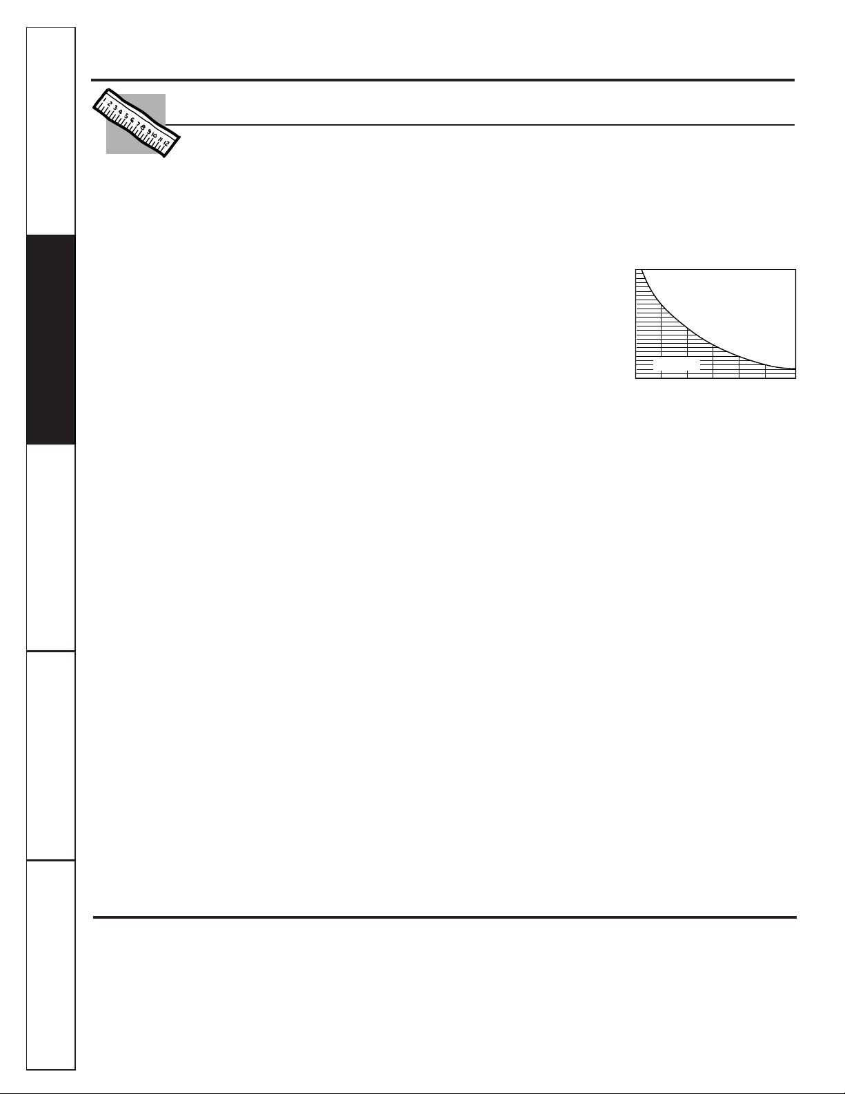
Incoming Water ph
WATER SOFTENER RECOMMENDED
INCOMING WATER HARDNESS (GPG)
60
50
40
30
2010
8
6
7
7.5
6.5
Water Softener
not required
Customer Service Troubleshooting Tips
Operating Instructions
Safety Instructions
Installation Instructions
Customer Service Troubleshooting Tips
Installation Instructions
Safety Instructions
Operating Instructions
Customer Service Troubleshooting Tips
Installation Instructions
Safety Instructions
Operating Instructions
Maximum iron, manganese, hydrogen sulfide (ppm) . . . . . . . . . . . . . . . . . . . . . . . . . . . .<0.1
Chlorine in water supply . . . . . . . . . . . . . . . . . . . . . . . . . . . . . . . . . . . . . . . . . . . . . . . . . . . .Allowable
b
Feed water pH limits (pH) . . . . . . . . . . . . . . . . . . . . . . . . . . . . . . . . . . . . . . . . . . . . . . . . . . .4–10
Product (quality) water, 24 hours—gallons . . . . . . . . . . . . . . . . . . . . . . . . . . . . . . . . . . . .10.0
a
Process water per gallon of product water, 24 hours—gallons . . . . . . . . . . . . . . . . . .5
Percent refection of TDS (new membrane) . . . . . . . . . . . . . . . . . . . . . . . . . . . . . . . . . . . .92
a
Cyst reduction . . . . . . . . . . . . . . . . . . . . . . . . . . . . . . . . . . . . . . . . . . . . . . . . . . . . . . . . . . . . .99.95%
Storage tank capacity—gallons . . . . . . . . . . . . . . . . . . . . . . . . . . . . . . . . . . . . . . . . . . . . .1.3
Automatic shutoff control . . . . . . . . . . . . . . . . . . . . . . . . . . . . . . . . . . . . . . . . . . . . . . . . . . .yes
Prefilter and postfilter . . . . . . . . . . . . . . . . . . . . . . . . . . . . . . . . . . . . . . . . . . . . . . . . . . . . . .(FX12PA) Carbon Block
Reverse Osmosis membrane . . . . . . . . . . . . . . . . . . . . . . . . . . . . . . . . . . . . . . . . . . . . . . . .(FX12M) Thin Film Polyamid
Dimensions (inches) . . . . . . . . . . . . . . . . . . . . . . . . . . . . . . . . . . . . . . . . . . . . . . . . . . . . . . . .height 16“ width 17” depth 6”
Feed water pressure limits—pounds per square inch (psi) . . . . . . . . . . . . . . . . . . . . . .40–125
c
Feed water temperature limits—minimum/maximum degrees F. . . . . . . . . . . . . . . . . .40–100
Maximum Total Dissolved Solids (TDS)—parts per million (ppm) . . . . . . . . . . . . . . . .2000
Maximum water hardness @ 6.9 pH—grains per gallon (gpg) . . . . . . . . . . . . . . . . . . .10
For water with hardness greater than 10 grains (at 6.9 pH) the use of a softener
is recommended. Failure to install a water softener will reduce the life of the
Reverse Osmosis membrane. See chart for additional information on the
possible need for a water softener.
a. Tested by NSF International according to ANSI/NSF Standard 58 has given 7.1 GPD. Source water test
parameters are 50 psig, 77°F, pH of 7.5 ± 0.5, and 750 ppm total dissolved solids.
b. Removed (maximum of 2.0 ppm) by the Reverse Osmosis prefilter.
REGULAR MAINTENANCE IS
REQUIRED.
Chlorine will destroy the Reverse Osmosis membrane.
c. If house water pressure is over 125 psi, install a pressure reducing valve in the water supply line. If house
water pressure is under 40 psi, install a Reverse Osmosis booster pump (contact your local plumbing
supply company).
5
Description of the Reverse Osmosis System
Prefilter
—Water from the cold supply pipe is directed to the prefilter cartridge, which is inside the sump.
The prefilter
is a replaceable sediment cartridge containing activated carbon. The cartridge removes sand, silt, dirt, other sediments
and up to 2.0 ppm of chlorine from the feed water. The prefilter reduces chlorine in the feed water because
CHLORINE
DESTROYS THE REVERSE OSMOSIS MEMBRANE.
Filtered, clean, chlorine-reduced water flows from the prefilter to the
Reverse Osmosis cartridge.
Storage Tank—
The storage area holds up to 1.3 gallons of product water. A diaphragm inside the tank keeps water
pressurized, when the tank is full, for fast flow to the faucet when drinking water is needed.
Check Valve—
A check valve is built into one end of the Reverse Osmosis housing under the tee fitting. The check valve
prevents a backward flow of product water from the storage area. A backward flow could cause the Reverse Osmosis
membrane to rupture.
Automatic Shutoff Assembly—
To conserve water, the drinking water system has an automatic shutoff. When the storage
tank has filled to capacity and the drinking water faucet is closed, pressure closes the shutoff. Water flow to the Reverse
Osmosis housing is shut off until drinking water is used again, and pressure drops in the Reverse Osmosis system.
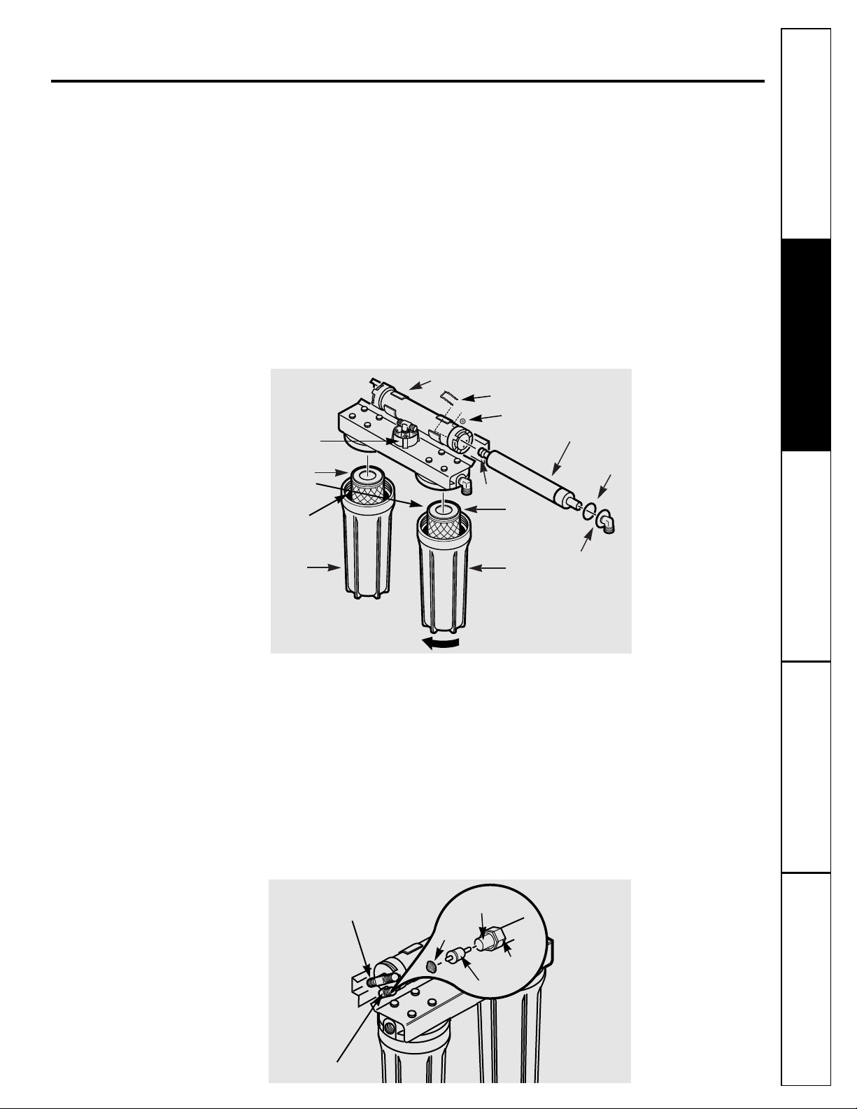
Sump
Sump
Postfilter
cartridge
Prefilter
cartridge
Inlet cover
O-ring
O-ring end
Reverse Osmosis cartridge
Reverse Osmosis housing
Turn sump this way to remove
O-ring
inside
sump
Reverse Osmosis Cartridge—
The cartridge, inside the Reverse Osmosis housing, includes a tightly wound, special
membrane. Water is forced through the cartridge where the membrane removes the dissolved solids and organic matter.
High quality product water exits the Reverse Osmosis housing and goes to the storage tank. Reject water, with the dissolved
solids and organic matter, leaves the housing and is discharged to the drain through 1⁄4″tubing.
Postfilter—
After leaving the storage area, but before going to the system faucet, product water goes to the postfilter
which is inside the sump. The postfilter is also a replaceable sediment cartridge that contains activated carbon. Any
remaining tastes, odors, or sediments are removed from product water by the postfilter. Clean, high quality drinking
water flows through the tubing and to the system faucet.
Flow Control—
The flow control regulates the flow of water through the Reverse Osmosis cartridge at the required rate
to produce high quality water. The control is located in the elbow fitting at the Reverse Osmosis housing drain port. A
small, cone-shaped screen fits over the front end of the flow control to prevent clogging due to sediments in drain water.
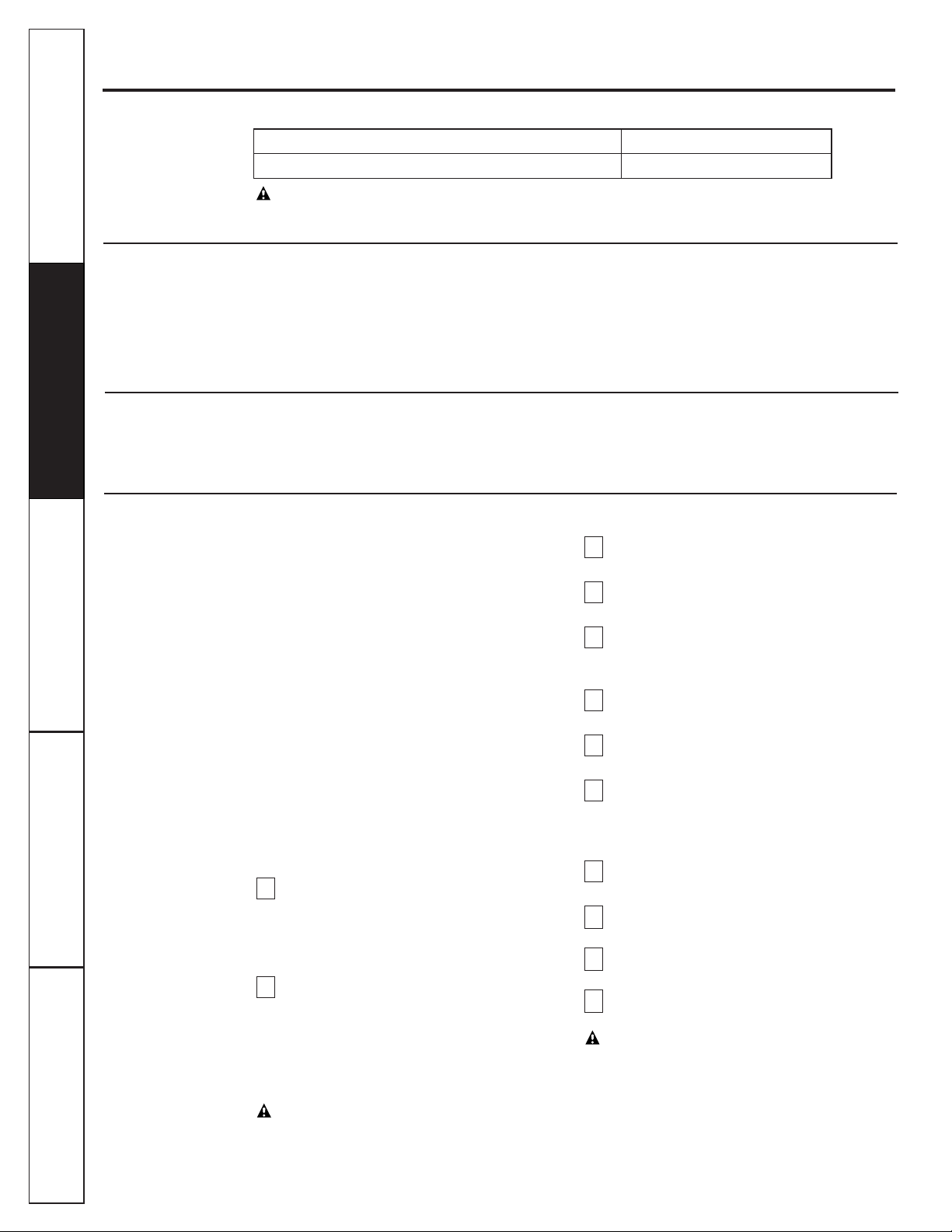
Screen
Flow control
To drain
1/4″
tubing
Compression nut
Check valve tee
Drain elbow
Automatic
shutoff
assembly
U-pin
Lock washer
Customer ServiceTroubleshooting Tips
Operating Instructions
Safety Instructions
Installation Instructions
NOTE: When replacing the Reverse Osmosis
cartridge, also install a new flow control and screen.
See the Flow Control and Screen section.
If the Reverse Osmosis Filtration system is
connected to your icemaker
YOU MUST
turn off
the icemaker by raising the feeler arm before
servicing the filter, changing the filters, or purging
the filtration system. Four hours after servicing
your unit, lower the feeler arm to resume
icemaking.
When replacing cartridges you may lift the
Reverse Osmosis assembly from the mounting
washers and lay it on the floor. You can also
remove the Reverse Osmosis housing by pulling
it out of the mounting clamps.
Be sure you clean your hands with anti-bacterial
soap before handling inner parts of the system.
Be sure the water supply valve to the Reverse
Osmosis system is turned off (turn clockwise)
and the RO
water faucet is open. Allow the
system to drain completely (this takes several
minutes).
Pull the Reverse Osmosis system out away
from cabinet. Leave tubing connected. Place a
dry towel under the Reverse Osmosis unit.
Using pliers remove the lock washer, pull the
u-pin and remove the Reverse Osmosis
housing inlet cover. Save the lock washer for
final assembly.
CAUTION:Failure to close the water supply valve
will cause water to spray or run when sumps are
removed.
Remove the lock washer, pull the u-pin and
remove the inlet cover from the housing.
Use pliers to pull the cartridge from the
housing and discard the cartridge.
Sanitize the system. Go to the
Sanitizing the
Reverse Osmosis System
section and follow
steps 4 through 11.
Install new flow control and screen. Go to the
Flow Control and Screen
section for directions.
Pull the u-pin and remove the inlet cover
from the housing.
Install the new Reverse Osmosis cartridge.
NOTE:
The Reverse Osmosis cartridge o-ring
end is notched and may need to be rotated
during reinstallation for proper fit.
Replace the inlet cover. Lightly lubricate the
o-ring seal with only clean silicone grease.
Insert the u-pin and install the lock washer.
Turn on the water supply. Check for leaks.
Purge the Reverse Osmosis system. Go to the
Purging the Reverse Osmosis System
section.
CAUTION:The Reverse Osmosis cartridge
contains a food grade preservative that should
be purged from the system before first use or
whenever the Reverse Osmosis cartridge is
replaced. The preservative will give product
water an unpleasant taste
and odor. After the
tank has filled (takes about four hours), open the
system faucet until the bladder is empty. After
four of these drainings, the system is ready to
make product water for your use
.
12
11
10
9
8
7
6
5
4
3
2
1
6
Care and cleaning of the reverse osmosis system.
To obtain replacement filters, call GE Appliance Parts at 800-626-2002.
CAUTION:Before servicing the Reverse Osmosis system, close the water supply/saddle valve and open
the RO water faucet. Allow the system to drain.
Prefilter/Postfilter Cartridge Replacement FX12PA Carbon Block
Reverse Osmosis Cartridge Replacement FX12M Thin Film Polyamide
Prefilter and Postfilter Cartridge Replacement
Follow the steps in the
Sanitizing the Reverse Osmosis System
section
EXCEPT
discard the old filters
and replace with new filters.
The Water Test Kit
This Reverse Osmosis system contains a replaceable treatment component, critical for effective
reduction of Total Dissolved Solids (TDS). This product water shall be tested periodically to verify
that the system is performing satisfactorily. Follow instructions included in the kit. Product water
should be tested a minimum of every six months. A replacement test kit will be provided to you
with the results of each test submittal.
Reverse Osmosis Cartridge Replacement
Customer Service Troubleshooting Tips
Operating Instructions
Safety Instructions
Installation Instructions
Customer Service Troubleshooting Tips
Installation Instructions
Safety Instructions
Operating Instructions
Customer Service Troubleshooting Tips
Installation Instructions
Safety Instructions
Operating Instructions
7
Customer ServiceTroubleshooting Tips
Operating Instructions
Safety Instructions
Installation Instructions
Sanitizing the Reverse Osmosis System
Sanitize upon installation of the Reverse Osmosis
system and after servicing inner parts, including
replacement of prefilter, postfilter and the
Reverse Osmosis cartridge.
Be sure you clean your
hands with anti-bacterial soap before handling inner
parts of the system.
CAUTION:
Before sanitizing, be sure to remove
all cartridges as follows.
Chlorine will destroy
the Reverse Osmosis cartridge.
Be sure the water supply valve to the Reverse
Osmosis system is turned off (turn
clockwise), and the RO water is faucet open.
Allow the system to drain completely (this
takes several minutes).
Pull the Reverse Osmosis system out away
from cabinet. Leave tubing connected. Place
a dry towel under the Reverse Osmosis unit.
Using pliers remove the lock washer, pull the
u-pin clip and remove the
Reverse Osmosis
housing inlet cover. Save the lock washer for
final assembly.
Remove (using pliers) the Reverse Osmosis
cartridge from the housing. Place the
cartridge in a clean plastic bag.
Replace the inlet cover and u-pin, making
sure the o-ring is in place.
Remove the POSTFILTER sump by turning
it to the left using the sump wrench tool
provided. Be careful, the sump is full of water.
Dispose of water in the sump. Remove the
cartridge from the sump and place in a clean
plastic bag. Make sure the o-ring is seated in
the top of the sump. With the o-ring seal in
position, replace the sump and tighten
securely by hand.
Remove the PREFILTER sump and cartridge.
Dispose of water in the sump. Place this
cartridge in a clean plastic bag.
Fill the prefilter sump with cold water to
about 1″ from the o-ring. Add 1 ounce (2
tablespoons)
of ordinary 5.25% household
chlorine bleach and mix into the water.
Do
not add chlorine first. Concentrated chlorine
may damage plastic.
Carefully replace the sump (make sure the
o-ring valve seal is in place) on the prefilter
head and tighten securely by hand.
Close the RO water faucet. Open the water
supply valve (turn counterclockwise) to the
Reverse Osmosis system. Allow system to fill
for one minute.
Open the RO water faucet and allow water
to flow for 10 minutes through the Reverse
Osmosis system. Close RO water faucet for
one minute and then open faucet and allow
water to flow (approximately 10 minutes)
until bleach odor is gone.
Turn off the water supply valve (turn
clockwise) to the Reverse Osmosis system.
After water flow stops, leave the RO water
faucet open.
Be sure hands have been cleaned with
anti-bacterial soap.
Repeat steps 1–6 and 8;
however, reinstall the cartridges instead of
removing them.
NOTE:
The Reverse Osmosis cartridge o-ring
end is notched and may need to be rotated
during reinstallation for proper fit.
After installing/reinstalling cartridges, close
RO water faucet and open water
supply valve
(turn counterclockwise). Check for leaks.
13
12
11
10
9
8
7
6
5
4
3
2
1
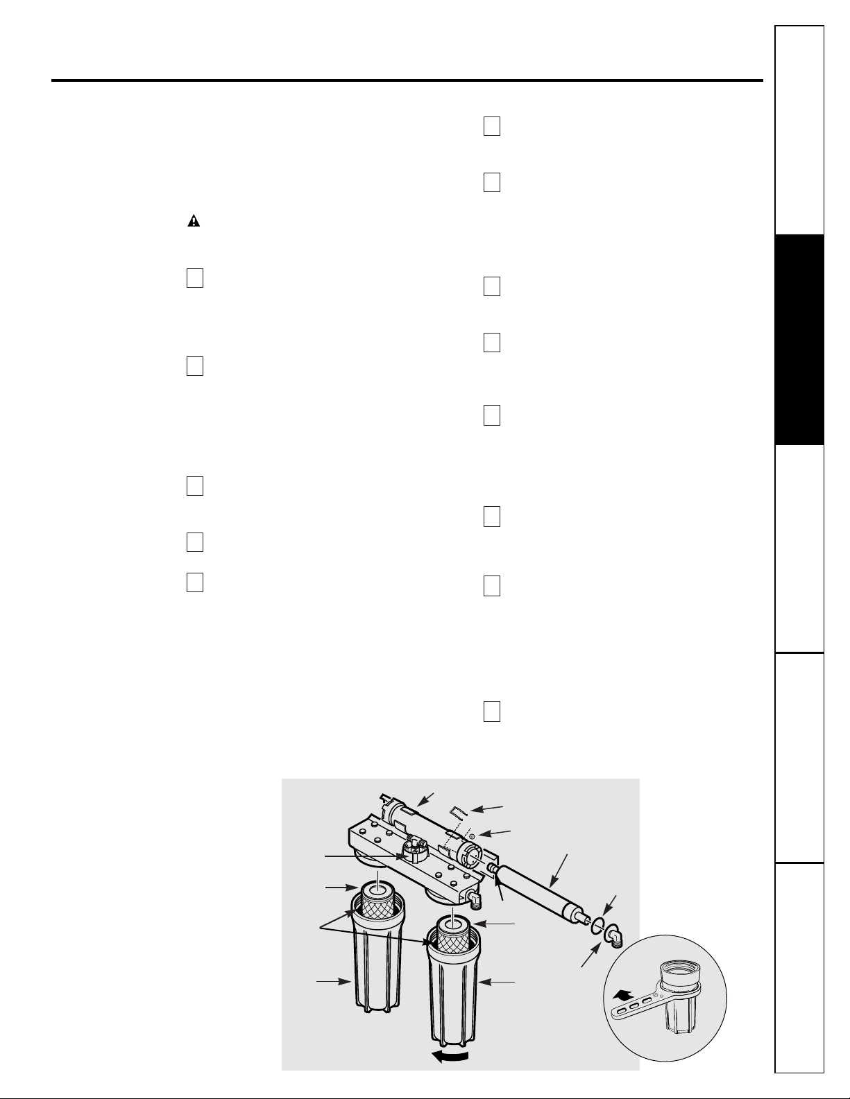
Sump
Sump
Postfilter
cartridge
O-ring end
Prefilter
cartridge
Inlet cover
O-ring
Reverse Osmosis cartridge
Reverse Osmosis housing
Turn sump this way to remove
O-ring
inside
sump
Automatic
shutoff
assembly
U-pin
Lock washer
Sump Wrench
Loosen
8
Care and cleaning of the reverse osmosis system.
Customer Service Troubleshooting Tips
Operating Instructions
Safety Instructions
Installation Instructions
Customer Service Troubleshooting Tips
Installation Instructions
Safety Instructions
Operating Instructions
Customer Service Troubleshooting Tips
Installation Instructions
Safety Instructions
Operating Instructions
Flow Control and Screen
The flow control regulates the flow of water
through the Reverse Osmosis cartridge at the
required rate so high quality product water is
produced.
When servicing the Reverse Osmosis cartridge,
check the flow control and tubing, to make sure
the tube and surrounding surfaces are clean
and unrestricted. A small, cone-shaped screen is
located in front of the flow control to help keep
it clean. If the flow control is plugged with
foreign particles, the Reverse Osmosis cartridge
cannot discharge minerals and impurities to the
drain. If this happens, it will only take a short
time for the system to plug.
Make sure the water supply valve is closed
(turn clockwise) and the RO water faucet is
open. Drain system until water stops flowing.
Locate the plastic drain elbow, next to the
brass check valve tee.
Unscrew the compression nut.
Remove flow control with a clean knife
edge. Remove screen; a toothpick may be
needed.
If you are replacing the flow control and
screen,
discard them. If you are checking
the flow control,
screen and tubing for
blockage, clean these parts of any debris.
Do not blow through the flow control, it will
contaminate the part.
Replace the screen by placing the cone end
into the elbow cap and carefully push it in.
CAUTION:
Do not force in further after you
feel resistance. Visually check to be sure it is
properly positioned.
I
nstall flow control and tighten
compression nut by hand, then another 1⁄4
turn with pliers.
DO NOT OVERTIGHTEN AND
DISTORT OR CRUSH THE TUBING AND FLOW
CONTROL.
If you are replacing the Reverse Osmosis
cartridge, return to the
Reverse Osmosis
Cartridge Replacement
instructions.
Otherwise, open the water supply valve
(turn counterclockwise). Close the RO
water faucet.
8
7
6
5
4
3
2
1
Purging the Reverse Osmosis System
The Reverse Osmosis system
MUST BE PURGED
AFTER INSTALLATION
and
WHEN THE REVERSE
OSMOSIS CARTRIDGE IS REPLACED.
Make sure all tubing connections are
tightened.
Turn on water supply by slowly opening
the
water supply valve (turn counterclockwise)
to the Reverse Osmosis system. Carefully
check system for leaks.
Fill sink(s) 1/2 full of tap water and drain,
checking drain plumbing for leaks.
Wait approximately four hours for storage
tank
to fill.
At that time,
carefully check all
fittings and tubing connections again for any
water leaks.
Open the RO water faucet until the tank is
empty and flow stops.
After filling and emptying the storage tank
four times, the system is ready to make
product water for your use.
WARNING:The Reverse Osmosis cartridge
contains a food grade preservative that should
be purged from the system before use or
whenever the Reverse osmosis cartridge is
replaced. The preservative will give product
water an unpleasant taste and odor.
6
5
4
3
2
1
REVERSE OSMOSIS
SYSTEM
Storage tank
1/4
″tubing,
marked WATER
SUPPLY
RO product water faucet
Drain line
Water supply valve
Hot
Cold
Sink
p-trap
Drain elbow
To drain
Screen
Compression
nut
1/4″ tubing
Flow control
Check valve tee

• Battery Powered Cordless Drill
• 1⁄4″ Drill Bit
• 1-1⁄4″ Carbide Hole Saw (if needed—see
Faucet Installation
section)
• Adjustable Open-End Wrenches
• Phillips and Straight Screw Drivers
• Utility Knife
• Teflon Tape
TM
• Contents Included with the Product:
— Reverse Osmosis Assembly
— Product Literature (Owner’s Manual and Installation, Use and Care Video, Performance Data
Sheet, and Owner Registration Card)
— Water Supply Valve Parts Bag
— Drain Line Adapter
— 27″ Length of 3⁄8″ Tubing
— Storage Tank
— Filter Replacement Reminder Label
INSTALLER RESPONSIBILITY: The water supply valve (see the
Feed Water Supply
section) is
included for use in areas where codes permit. Installer must comply with state and/or local codes.
If not, the installer must provide fittings to tap the cold water pipe for a feed water source to the
Reverse Osmosis system (must adapt to 1/4″OD tubing).
Installation instructions.
9
Customer ServiceTroubleshooting Tips
Operating Instructions
Safety Instructions
Installation Instructions
Important Installation Recommendations
Read entire manual. Failure to follow all guides and rules could cause personal injury or property
damage.
• BE SURE TO FOLLOW ALL APPLICABLE STATE AND LOCAL CODES.
• Use a qualified installer.
• Do not install the Reverse Osmosis system outside or in extreme hot or cold temperatures.
DO NOT INSTALL ON HOT WATER.
• Recommended installation is under the sink. However, the unit can be installed in a remote
location, up to 30 feet away from the sink. Additional installation materials may be required.
• If Reverse Osmosis system is connected to a refrigerator icemaker, a special icemaker connection
kit is required (RVKIT). Do not use copper tubing for the connection between the Reverse
Osmosis system and the refrigerator.
• Be sure the water supply conforms to the specifications, see the
Specifications Guidelines
section. If
water supply conditions are unknown, contact your municipal water company or your local health
department for a list of
contaminants in your area and a list of laboratories certified by your state to
analyze drinking water.
WARNING:
Do not use with water that is microbiologically unsafe or of unknown quality without
adequate disinfection before or after the system. Systems certified for cyst reduction may be
used on disinfected water that may contain filterable cysts. This Reverse Osmosis system
contains a replaceable treatment membrane cartridge critical for effective reduction of Total
Dissolved Solids. The water should be tested periodically to verify that the system is performing
satisfactorily. This system is acceptable for treatment of influent concentrations of no more
than 27 mg/L nitrate and 3 mg/L nitrite in combination measured as N and is certified for
nitrate/nitrite reduction only for water supplies with a pressure of 280kPa (40 psig) or greater.
Small parts remaining after the installation could be a choke hazard. Discard safely.
Tools and Materials Required for Installation

10
Installation instructions.
Customer Service Troubleshooting Tips
Operating Instructions
Safety Instructions
Installation Instructions
Customer Service Troubleshooting Tips
Installation Instructions
Safety Instructions
Operating Instructions
Customer Service Troubleshooting Tips
Installation Instructions
Safety Instructions
Operating Instructions
Things to Check Before Beginning Installation
FEED WATER—
The water supply to the
undercounter Reverse Osmosis system must
have the qualities listed in the specifications
(see the
Specifications Guidelines
section).
Municipal water supplies most often will
have these qualities.
Well water may need
conditioning—
have the water tested by a
water analysis laboratory and get their
recommendations for treatment.
CAUTION:
For water with a hardness
greater than 10 grains (at 6.9 pH),
the use of a softener is recommended.
Failure to install a softener will reduce
the life of the Reverse
Osmosis
membrane. See the
Specifications
Guidelines
section for additional
information on the possible need
for a softener.
DRAIN POINT*—
A suitable drain point and air
gap
(check your local codes)
are needed for
reject water from the Reverse Osmosis
membrane cartridge.
RO FAUCET—
The RO product water faucet
installs on the sink or on the countertop next
to the sink. Often, it is installed in an existing
sink spray attachment hole. Space is required
underneath for tubing to and from the faucet,
and for securing the faucet in place. All faucet
connections and installation procedures are
done on or above the sink or countertop.
Refer to Fig. 1 below.
BASEMENT INSTALLATION–
If installing in a
basement, leave enough tubing in place
during installation to be able to move unit to
floor for ease at servicing and making
filter/membrane changes.
FIG 1. INSTALLATION
OVERVIEW
Sump wrench
provided
RO product water faucet
mounted through sink
3⁄8″
drain tubing
Water supply
valve or
compression
fitting
Hot Cold
Sink p-trap
Drain line*
6 1/4″
15″
16″
9″ dia.
17″
Depth
5 1⁄2″
Reverse Osmosis system
Storage tank
*For drain line options see
Filtration Drain Connection Installations
section.

Step-by-step installation instructions.
Customer ServiceTroubleshooting Tips
Operating Instructions
Safety Instructions
Installation Instructions
11
Feed Water Supply
Check and comply with local plumbing codes as you plan, then install a cold feed water supply fitting.
For new home installation using standard plumbing fittings, see Fig. 2A below. A typical installation
for existing homes using the saddle valve is shown in Fig. 2B below.
A. PREFERRED INSTALLATION
B. OPTIONAL INSTALLATION Where codes permit
NOTE:
Codes in the state of Massachusetts require installation by a licensed plumber and do not
permit the use of the saddle valve. For installation, use plumbing code 248-CMR of the
Commonwealth of Massachusetts.
OPTIONAL WATER SUPPLY CONNECTION (using saddle valve)
Pre-drill
1⁄4″ hole
Seal—make sure
the seal is in place
Clamp X
Nut (2)—not
required if
holes in
clamp are
threaded
Valve
Handle
Nut
Ferrule
Insert
Use to connect the tubing, step 2, in the
Faucet
Drain Tubing and Water Supply Tubing
section.
❵
Clamp Z
Fig. 2B.
Turn off the cold water
supply and attach saddle
valve as shown in Fig. 2B.
DANGER:
To protect yourself
from serious injury or fatal
shock, use a battery powered
hand drill only to make the
hole.
DO NOT USE AN
ELECTRIC DRILL.
Close the water supply valve
by turning the handle
clockwise.
Open the main water supply
valve and several house
faucets to purge air from the
system. Close faucets when
water runs smoothly.
321
Turn off the cold water supply. Complying with plumbing codes, install a
fitting on the cold water pipe to adapt 1⁄4″
OD tubing. A typical connection is shown
in Fig. 2A (parts not included). Make sure a
water supply valve is used.
21
Fig. 2A.
PREFERRED WATER SUPPLY CONNECTION
(using compression fitting)
1⁄4″compression fitting
Insert
Cold
water
pipe
1⁄4″ tubing to Reverse Osmosis
inlet, step 2, in the
Faucet Drain
Tubing and Water Supply Tubing
section.
Ferrule
Water supply valve
TYPICAL LOCATION
Cold
water

Step-by-step installation instructions.
Filtration Drain Connection Installations
Customer Service Troubleshooting Tips
Operating Instructions
Safety Instructions
Installation Instructions
Customer Service Troubleshooting Tips
Installation Instructions
Safety Instructions
Operating Instructions
Customer Service Troubleshooting Tips
Installation Instructions
Safety Instructions
Operating Instructions
Check and comply with all state and local plumbing codes as
you plan.
CAUTION:
The options detailed below are the ONLY
approved installation configurations. Do not use any drain
saddle device.
NOTE:
Failure to follow these Installation Instructions will void
the Warranty, and the Installer will be responsible for any
service, repair, or damages caused thereby.
Preferred Installation Options
(Options A, B and C)
OPTION A.
BASEMENT ACCESS INSTALLATION (Fig. 3A)
Route the drain line DIRECTLY from the Reverse Osmosis
system to a standpipe in the basement, by-passing the air gap
provided in the faucet. The drain line may also be routed in the
basement to a floor drain or washtub, provided that the air gap
in the basement is maintained. Avoid dips, loops or low spots
in the drain line. The basement air gap and drain installation
configuration must conform to all local codes. Special air gap
fittings are available to connect the drain line to the top of
the standpipe.
OPTION B.
SEPARATE VENT INSTALLATION—
2 P-TRAP (DRY-VENTED) (Fig. 3B)
Install a separate dry-vented p-trap under the sink to be used
exclusively for the Reverse Osmosis drain line. A dry-vented
p-trap is a p-trap that has its own vent/stack. Attach the
provided drain line adapter to the p-trap and secure it with
the slip joint nut and washer as shown. Route the drain line
from the air gap to the drain line adapter ensuring that there
are no dips, loops or low spots in the line, which could result in
a clogged drain line. The drain line adapter should be aligned
vertically such that the hose connection points in a direction
45° off vertical. (See Fig. 3E.) The drain line must be routed
through the air gap provided in the RO water faucet.
OPTION C.
SHARED VENT INSTALLATION—
2 P-TRAP (WET-VENTED) (Fig. 3C)
Install a p-trap under the sink to be used exclusively for the
Reverse Osmosis drain line. A wet-vented p-trap is a p-trap that
shares a common vent/stack. Attach the provided drain line
adapter to the p-trap and secure it with the slip joint nut and
washer as shown. Route the drain line from the air gap to the
drain line adapter ensuring that there are no dips, loops or low
spots in the line, which could result in a clogged drain line. The
drain line adapter should be aligned vertically such that the
hose connection points in a direction 45° off vertical. (See
Fig. 3E.) The drain line must be routed through the air gap
provided in the RO water faucet. Locate the p-trap as high as
possible (minimum of 4″above horizontal pipe from second
sink or disposer).
Fig. 3A.
Fig. 3B.
Fig. 3C.
From second
sink or disposer
From second sink or
disposer
From second
sink or disposer
From
faucet air
gap
Drain line from
Reverse Osmosis
by-passing faucet
air gap
Maintain air gap
at drain point in
basement
Drain line adapter
Separate p-trap
Cap (not
included)
Cap (not
included)
4″
Min.
From faucet air gap
Drain line adapter
12

Customer ServiceTroubleshooting Tips
Operating Instructions
Safety Instructions
Installation Instructions
Secondary Recommendation
(Use only if option A, B or C is not possible.)
OPTION D.
DRAIN LINE ADAPTER INSTALLATION (FIG. 3D)
DO NOT install the drain line downstream of a disposal
or in a horizontal pipe. Install the provided drain line
adapter under the sink as shown. The baffle-tee or
y-connector shown must be in place (purchase and install
if necessary) to prevent a clog in the Reverse Osmosis
drain line. Route the drain line from the air gap to the
drain line adapter ensuring that there are no dips, loops
or low spots in the line, which could result in a clogged
drain line. The drain line adapter should be aligned
vertically so that the hose connection points in a direction
45°off vertical. (See Fig. 3E.) This installation MAY result
in a slight drain noise in the sink drain when the Reverse
Osmosis system is operating. Rotate the Drain Line
adapter tee assembly slowly until noise is minimized.
Generally, 180° opposite the existing horizontal
pipe/baffle-tee is a good orientation.
Fig. 3D.
Fig. 3E.
Mandatory baffle-tee
or y-connector
From second
sink or disposer
45°
From faucet air gap
Drain line
adapter
Drain line connection should
be 180° opposite existing
horizontal pipe/baffle-tee
as shown in diagram
Drain line adapter
Proper drain line adapter orientation.
13

14
Step-by-step installation instructions.
Faucet Installation
Be sure there is room underneath the sink to make the
needed connections. Select one of the following places to
install the faucet:
—IN an existing sink spray attachment or soap dispenser
hole.
—IN a hole to be drilled in the sink top.
—IN a hole to be drilled in the countertop, next to the sink.
NOTE:
Looking at Fig. 4B, be sure the faucet base will fit
flat against the surface at the selected location so the gasket
will seal.
If drilling is needed, make a 1-1⁄4² dia. hole.
Be sure to use the proper procedure for drilling
porcelain or stainless steel.
Place base on threaded stem (flange facing down).
Next, place large gasket on threaded stem, making sure
the stem and two barbed studs fit through the gasket.
Place spacer on stud (open end up) followed by metal
washer and hex nut (Fig. 4A).
Insert washer into tubing adapter. Securely tighten to
faucet stud.
Take the 27² length of 3⁄8²tubing and push one end
completely onto the 3⁄8²faucet barb fitting (Fig. 4B).
Position the Reverse Osmosis system under the sink.
Referring to Fig. 5, on the next page, hang the system on
cabinet wall.
Route the 1⁄4²tubing (marked “1⁄4² BARB
ON FAUCET”) and the 3⁄8²tubing (marked
“FAUCET”) up through the mounting hole:
a. Push one end of the 1⁄4²tubing onto the 1⁄4² barb
on the faucet.
b. Using the compression nut, fasten the 3⁄8²tubing to
the tubing adapter and tighten the nut. Make sure the
tubing is completely seated in the adapter.
Remove the short shipping tube and insert the spout
into the faucet body.
Lower the faucet assembly through the sink.
Under the counter,
place the mounting plate above spacer
and securely tighten the hex nut.
9
8
7
6
5
4
3
2
1
Customer Service Troubleshooting Tips
Operating Instructions
Safety Instructions
Installation Instructions
Customer Service Troubleshooting Tips
Installation Instructions
Safety Instructions
Operating Instructions
Customer Service Troubleshooting Tips
Installation Instructions
Safety Instructions
Operating Instructions
Fig. 4A.
Fig. 4B.
Spacer
Mounting plate
Base
Hex nut
Faucet
Lever
Spout
NOTE: For ease of service and
maintenance, keep tubing lengths
long enough so removal of the
Reverse Osmosis system from
under the sink is possible.
Faucet
stud
Large gasket
Compression nut
Metal washer
Tubing adapter
Tubing adapter
Plastic washer
3/8² barb fitting
1/4² tubing
marked 1/4² barb
1/4² barb fitting
3/8² tubing
marked FAUCET
3/8² tubing,
27² long
Compression nut
ASSEMBLED
From RO
To drain
From RO

Faucet Drain Tubing and Water Supply Tubing
Customer ServiceTroubleshooting Tips
Operating Instructions
Safety Instructions
Installation Instructions
If Option A, BASEMENT ACCESS INSTALLATION, see
Filtration Drain Connection Installations
section, was used,
go to step 2.
If Option B, C or D from page 13 was used, connect
the faucet drain tubing by running the 27² length,
3⁄8²tubing from the 3⁄8² faucet barb to the drain fitting
(installed in
Filtration Drain Connection Installations
section). Keep this tubing run as short and straight as
possible, without loops, dips, or low-spots. Cut the tubing
as needed and insert into the drain fitting (see Fig. 3B,
3C or 3D in the
Filtration Drain Connection Installations
section).
To connect the water supply tubing: Run the 1⁄4²tubing
(marked “WATER SUPPLY”) from the Reverse Osmosis
inlet to the feed water supply fitting (see Fig. 2A or 2B,
in the
Feed Water Supply
section). Connect the tubing as
applies (Fig. 2A or 2B, in the
Feed Water Supply
section)
and tighten the nut securely (use Teflon Tape™ to
prevent leaks).
Apply the Filter replacement reminder label to one
of the filter sumps between the ribs. Mark the date for
filter replacement six months from the installation date.
3
2
1
15
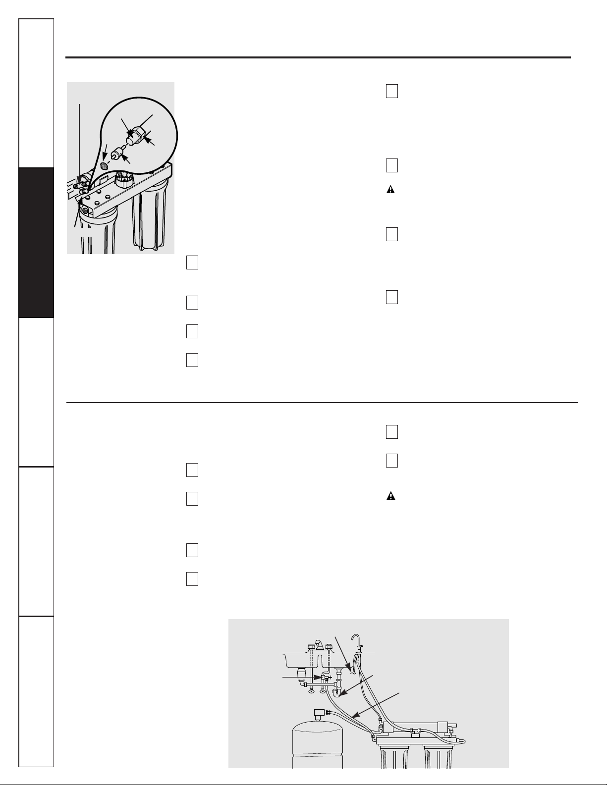
Fig. 5.
3⁄8²
drain tubing
Drain line*
Water supply
valve or
compression
fitting
Hot Cold
Automatic shutoff assembly
Storage tank
*For drain line options see
Reject Water Drain Fitting
section.
RO inlet
Filter Replacement Reminder Label

16
Step-by-step installation instructions.
Reverse Osmosis System Assembly and Storage Tank Installation
1. Hold the Reverse Osmosis assembly up to the wall surface where you will install it. Mark
locations for the hanger washers and screws.
2. Fasten the hanger washers to the wall surface. Wood screws are included for fastening to
a wood surface. Provide other screws as needed.
3. Hang the Reverse Osmosis assembly on the hanger washers.
4. Connect the tubing to the storage tank: Run the length of 3⁄ 8² tubing (marked
“STORAGE TANK”) from the tee fitting on the Reverse Osmosis module to the tank
shutoff valve. Use Teflon TapeTMto prevent leaks.
Customer Service Troubleshooting Tips
Operating Instructions
Safety Instructions
Installation Instructions
Customer Service Troubleshooting Tips
Installation Instructions
Safety Instructions
Operating Instructions
Customer Service Troubleshooting Tips
Installation Instructions
Safety Instructions
Operating Instructions
Fig. 6A.
Storage tank
Hanger
washer
(2)
Screw
(2)
10²
2² minimum clearance
for changing cartridges
Fig. 6B.
RO faucet
Reverse Osmosis
system
Cold
water
supply
Sink
p-trap
Storage tank
*For drain line options see
Filtration Drain Connection Installations
section.

Now That Your Reverse Osmosis System is Installed…Sanitize
Customer ServiceTroubleshooting Tips
Operating Instructions
Safety Instructions
Installation Instructions
Sanitize upon installation and after servicing inner parts, including replacement of
prefilter, postfilter and the Reverse Osmosis cartridge. It is important to wash hands with
anti-bacterial soap before handling inner parts of the system. See the
Sanitizing the Reverse
Osmosis System
and
Purging the Reverse Osmosis System
sections.
CAUTION:
If installing unit in New Construction, ensure house plumbing is flushed
thoroughly before opening the water supply valve. Also, before sanitizing, be sure to
remove all cartridges as described in the
Sanitizing the Reverse Osmosis System
section
.
Chlorine will destroy the Reverse Osmosis cartridge.
17
Installation Checklist
1. Are all tubing connections tightened? Do they run between the points shown? No leaks!
2.
Did you use drain option B, C or D? Make sure the 3⁄8²drain tubing, from the faucet to
the drain point, is without loops, dips, or low-spots.
3. Is the water supply shutoff valve open?
4. Did you sanitize and purge the system?

18
Before you call for service…
Customer Service Troubleshooting Tips
Operating Instructions
Safety Instructions
Installation Instructions
Customer Service Troubleshooting Tips
Installation Instructions
Safety Instructions
Operating Instructions
Customer Service Troubleshooting Tips
Installation Instructions
Safety Instructions
Operating Instructions
Problem Possible Causes What To Do
Sounds you might hear
Running water from the unit • This is normal.
to a drain.
Water has air bubbles
Air in system after installation. • Will go away after water runs for a while.
and is cloudy
Chlorine taste and/or
The ppm of chlorine in your
• If the water supply contains more than 2.0 ppm of
odor in the Reverse
water supply exceeds maximum
chlorine,
additional filtering of the water supply to the
Osmosis product water
limits and has destroyed the Reverse Osmosis is needed. Correct this condition before
Reverse Osmosis membrane. doing maintenance on the Reverse Osmosis system.
The prefilter is no longer • Replace the Reverse Osmosis membrane cartridge,
removing chlorine from control, screen, prefilter and postfilter
the water supply.
Other taste and/or odor
High quality product water • This is normal.
may have a different taste
than what you’re used to.
Low water usage • Completely drain system and allow to refill.
Contamination in product
•
Use sanitizing procedures.
water storage.
Prefilter and postfilter
• Replace the prefilter and postfilter. If taste and odor
need to be changed and/or persists, replace the Reverse Osmosis cartridge, flow
the Reverse Osmosis cartridge control and screen.
needs to be changed.
Water leaking from
Drain side of faucet air gap • Inspect and eliminate restriction or plug. It is important
faucet air gap hole
(3/8² tubing) plugged, restricted that there are no dips, loops or low spots in the drain line
or incorrectly connected to the from the faucet air gap to the drain pipe. Refer to the
drain point.
Filtration Drain Connection Installations
section, for proper
drain connection. If drain line adapter was used as the
drain point, periodic inspection/cleaning is recommended.
System makes product
This is normal. • Water flow rate will be lower than your regular faucet.
water slowly
Water supply to the Reverse • Increase water pressure, precondition the water, etc., as
Osmosis system not within needed to conform before doing maintenance on the
specifications. Reverse Osmosis system.
Prefilter cartridge plugged • Replace the prefilter.
If rate does not increase,
replace
with sediments and/or the the postfilter, Reverse Osmosis cartridge, flow control,
Reverse Osmosis cartridge and screen.
plugged with sediments.
Troubleshooting Tips
Save time and money! Review the charts on the following
pages first and you may not need to call for service.

19
General Electric Company
Warranty Registration Department
P.O. Box 34070
Louisville, KY 40232-4070
GE Service Protection Plus
™
GE, a name recognized worldwide for quality and dependability, offers you Service
Protection Plus
™
—comprehensive protection on all your appliances—No Matter
What Brand!
Benefits Include:
•Backed by GE
•All brands covered
• Unlimited service calls
•All parts and labor costs included
•No out-of-pocket expenses
•No hidden deductibles
•One 800 number to call
You will be completely satisfied with our service protection or you may request your money back
on the remaining value of your contract. No questions asked. It’s that simple.
Protect your refrigerator, dishwasher, washer and dryer, range, TV, VCR and much more—any brand!
Plus there’s no extra charge for emergency service and low monthly financing is available. Even icemaker
coverage and food spoilage protection is offered. You can rest easy knowing that all your valuable
household products are protected against expensive repairs.
Place your confidence in GE and call us in the U.S. toll-free at 800-626-2224
for more information.
*All brands covered, up to 20 years old, in the continental U.S.
We’ll Cover Any Appliance.
Anywhere. Anytime.*
Please place in envelope and mail to:
✁
Cut here

20
Consumer Product Ownership Registration
Model Number Serial Number
Important
Mail
Today!
GE Appliances
General Electric Company
Louisville, Kentucky 40225
First
Name
Mr. ■■ Ms. ■■ Mrs. ■■ Miss ■■
Street
Address
City
State
Date Placed
In Use
Month
Day
Year
Zip
Code
Apt. #
Last
Name
Phone
Number
_ _
Consumer Product Ownership Registration
Dear Customer:
Thank you for purchasing our product and thank you for placing your
confidence in us. We are proud to have you as a customer!
Follow these three steps to protect your new appliance investment:
Complete and mail
your Consumer
Product Ownership
Registration today.
Have the peace of
mind of knowing we
can contact you in
the unlikely event of
a safety modification.
After mailing
the registration
below, store this
document in a safe
place. It contains
information you
will need should
you require service.
Our service number
is 800-GE-CARES
(800-452-2737).
Read your Owner’s
Manual carefully.
It will help you
operate your new
appliance properly.
If you have questions,
or need more
information call the
GE Answer Center
®
800.626.2000.
Important: If you did not get a registration card with your product,
detach and return the form below to ensure that your
product is registered.
1
2 3
Model Number Serial Number
✁
Cut here

LITERATURE
Customer ServiceTroubleshooting Tips
Operating Instructions
Safety Instructions
Installation Instructions
41*
37
36
67
34
33
32
9
10
66
14
30
9
24
9
26
63
14
61
62
12
13
47, 48,
49, 50
(ART NO.
WH754 C)
62
64
27
23
22
21
28
9
10
66
65
69
10
25
200
10
13
999
43
44
70
3
4
5
7
6
8
57
45
58
24
35
53
68
59
60
10
9
1
24
*NOTE:
Codes in the State of Massachusetts
require installation by a licensed plumber and
do not permit the use of the saddle valve. For
installation, use plumbing code 248-CMR of
the Commonwealth of Massachusetts.
21
Parts list

22
General Electric parts catalog
Customer Service Troubleshooting Tips
Operating Instructions
Safety Instructions
Installation Instructions
Customer Service Troubleshooting Tips
Installation Instructions
Safety Instructions
Operating Instructions
Customer Service Troubleshooting Tips
Installation Instructions
Safety Instructions
Operating Instructions
REF. NO. PART NO. PART DESCRIPTION GXRV10ABL01
0001 WS15X10003 FAUCET WHITE TIP & LEVER -
WS15X10011 FAUCET BLACK TIP & LEVER 1
0004 WS02X10007 SCREW #6-32 X 1 -3/8² 2
0006 WS08X10003 GASKET FAUCET 1
0007 WS02X10008 NUT 2
0008 WS03X10003 ADAPTER TUBING 1
0009 WS22X10005 NUT 1/4² TUBE 8
0010 WS22X10006 INSERT 1/4² TUBE 7
0012 WS22X10007 INSERT 3/8² TUBE 7
0013 WS22X10008 NUT 3/8² TUBE 7
0014 FX12PA CARTRIDGE–CARBON/SED 2
0017 WS03X10004 WASHER FLOW 1
0018 WS01X10001 MAGNET 1
0019 WS03X10005 SPRING 1
0021 WS10X10005 VALVE BOTTOM 1
0022 WS22X10009 DIAPHRAGM 2
0023 WS22X10010 PLUNGER 1
0024 WS22X10012 ELBOW 1/8² NPT X 1/4² 1
WS22X10011 ELBOW 1/8² NPT X 1/4² & NUT 3
0025 WS22X10013 CONNECTOR W/NUT 1/8 NPT 1
WS22X10014 CONNECTOR 1/8 NPT X 1/4 1
0026 WS10X10006 VALVE TOP 1
0027 WS10X10007 VALVE CENTER 1
0028 WS02X10010 SCREW # 10-14 X 1-3/4² 4
0030 WS32X10006 TANK–2.1 GAL. 1
0032 WS02X10018 CLIP 2
0033 WS02X10017 SCREW 4
0034 WS10X10012 CHECK BALL ASM 1
0035 WS20X10004 CARTRIDGE–R.O. 1
0036 WS22X10024 TEE 3/8² TUBING 1
0037 WS02X10004 NUT 3/8² 2
0041 WS15X10008 WATER SUPPLY VALVE* 1
0043 WS03X10015 SCREEN CONE 1
0044 WS03X10016 CONTROL FLOW 1
0045 FX12M MEMBRANE CARTRIDGE 1
0047 WS07X10005 TUBING 1/4² X 10 FT 1
0048 WS07X10006 TUBING 1/4² X 20 FT 1
0049 WS07X10007 TUBING 3/8² X 20 FT 1
0050 WS07X10008 TUBING 3/8² X 20 FT 1
0053 WS03X10026 U-PIN 1
0057 WS03X10028 O-RING 1-19/32² ID 2² OD 1
0058 WS31X10009 COVER INLET 1
0059 WS02X10001 SCREW #10-14 X 3/4² 8
0060 WS28X10006 BRACKET 1
0061 WS19X10001 HEAD 2
0062 WS22X10002 ELBOW 3/8² NPT X 3/8² 2
0063 WS03X10001 O-RING 3-3/8² X 3-5/8² 2
0064 WS30X10001 SUMP 2
0065 WS22X10025 TEE 3/8 NPT X 3/8 TUBE 1
0066 WS22X10026 ELBOW 3/8 NPT X 1/4 TUBE 2
0067 WS03X10030 SPRING 1
0068 LOCK WASHER 1
0069 FLOW RESTRICTER
0070 DRAIN LINE ADAPTER
0200 WX5X140 WRENCH SUMP 0999 49-50005 PM MANUAL USE & CARE/ 1
INSTALLATION
PERFORMANCE DATA SHEET
VIDEO
WATER TEST KIT
*NOTE:
Codes in the State of
Massachusetts require installation
by a licensed plumber and do not
permit the use of the saddle valve.
For installation, use plumbing code
248-CMR of the Commonwealth of
Massachusetts.

GE Reverse Osmosis System Warranty
Customer ServiceTroubleshooting Tips
Operating Instructions
Safety Instructions
Installation Instructions
23
For The Period Of: GE Will Replace, At No Charge To You:
One Year Any part
of the Reverse Osmosis Filtration System which fails due to a defect in materials or
From the date of the
workmanship. During this
limited one-yearwarranty,
GE will also provide,
free of charge,
all labor
original purchase
(does not include service trip to home) to replace the defective part.
All warranty service provided by our Factory Service Centers, or an authorized Customer Care®technician.
For service, call 800-GE-CARES.
■ Service trips to your home to teach you how to use the
product.
■ Improper installation.
■ Failure of the product if it is abused, misused, or used for
other than the intended purpose or used commercially.
■ Filters or membranes.
■ Use of this product where water is microbiologically
unsafe or of unknown quality, without adequate
disinfection. Systems certified for cyst reduction may be
used on disinfected water that may contain filterable cysts.
■ Replacement of house fuses or resetting of circuit
breakers.
■ Damage to the product caused by accident, fire, floods or
acts of God.
■ Incidental or consequential damage to personal property
caused by possible defects with this appliance.
What GE Will Not Cover:
This warranty is extended to the original purchaser and any succeeding owner for products purchased for home
use within the USA. In Alaska, the warranty excludes the cost of shipping or service calls to your home.
Some states do not allow the exclusion or limitation of incidental or consequential damages. This warranty gives
you specific legal rights, and you may also have other rights which vary from state to state. To know what your legal
rights are, consult your local or state consumer affairs office or your state’s Attorney General.
Warrantor: General Electric Company. Louisville, KY 40225

Printed in Louisville, KY
24
Service Telephone Numbers.
GE Answer Center
®
800.626.2000
The GE Answer Center® is open 24 hours a day, 7 days a week.
In-Home Repair Service
800-GE-CARES (800-432-2737)
Expert GE repair service is only a phone call away.
Special Needs Service
800.626.2000
800-TDD-GEAC (800-833-4322)
GE offers, free of charge, a brochure to assist in planning a barrier-free kitchen for persons
with limited mobility.
Service Contracts
800-626-2224
Purchase a GE service contract while your warranty is still in effect and you’ll receive a
substantial discount. GE Consumer Service will still be there after your warranty expires.
Parts and Accessories
800-626-2002
Individuals qualified to service their own appliances can have parts or accessories sent directly
to their homes (VISA, MasterCard and Discover cards are accepted).
Instructions contained in this manual cover procedures to be performed by any user. Other servicing
generally should be referred to qualified service personnel. Caution must be exercised, since
improper servicing may cause unsafe operation.
Service Satisfaction
If you are not satisfied with the service you receive from GE:
First,
contact the people who serviced your appliance.
Next,
if you are still not pleased, write all the details—including your phone number—to:
Manager, Consumer Relations
GE Appliances
Appliance Park
Louisville, KY 40225
Finally,
if your problem is still not resolved, write:
Major Appliance Consumer Action Program
20 North Wacker Drive
Chicago, IL 60606
Operating Instructions Safety InstructionsCustomer Service Troubleshooting Tips
 Loading...