

GE Security GuardSwitch Series 300 301-BT, GuardSwitch Series 300 303-BT Installation Guide
Page 1
Description
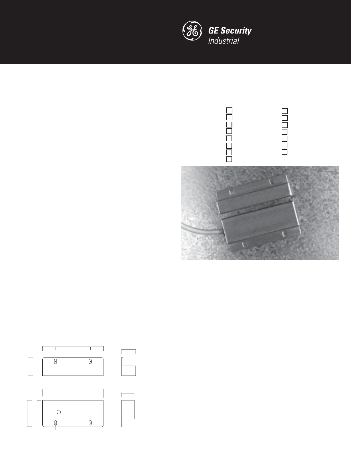
The 301-BT Series 300 DPST safety interlock switch is designed for use with safety
monitored relays or monitored circuits. To achieve the optimum Series 300 defeat
resistant feature of the 301-BT, both the switch circuit (Circuit 1) and the tamper
circuit (Circuit 2) must be connected. An optional third circuit can be provided to
indicate at the panel which guard is open.
Notes:
1. Environmental: Pollution Degree II
2. Correct use of this control device is an essential part of proper machine cycle
control.
3. Failure to follow ALL instructions could lead to serious bodily injury or death.
4. Maintenance to be done by qualified personnel only
5. The connecting cables between the INT devices and the switches must be located in
an IP 23 type enclosure (minimum).
6. The mounting for the switch and the actuator magnet must be accomplished per
this specification.
7. Non-removable hardware must be used for installation.
8. The housing of the 300-BT must be connected to the PE (Primary Earth) ground
circuit via a lock washer on the mounting screw. The PE ground symbol must be
placed adjacent to the screw.
To verify switch operation with an ohmmeter:
Set range at 20 mega ohms (switches with triac output, set ohm range at
20 kilo ohms). For a normally open switch, the meter will read a high impedance with
the actuator away. It will read very high to infinity range (triac switches will read high
kilo ohm to infinity range) with the actuator within sense range. You will see the
opposite reading for a normally closed switch.
Dimensions
0.98''
2.49cm
1.48''
3.76cm
0.57''
1.45cm
0.69''
1.75cm
0.40''
1.02cm
0.67''
1.70cm
0.16'' x 0.24''
0.41cm x 0.61cm
slot
3.07''
7.80cm
1.75''
4.45cm
3.07''
7.80cm
2.13''
5.41cm
0.20''
0.51cm
0.74''
1.88cm
0.66''
1.68cm
GuardSwitch™ Series 300
Safety Interlock Switch
301-BT-06(J)(K)
301-BT
301-BT-06J-NH
301-BT-12(J)(K)
303-BT
301-BT-12J-NH
301-BT-15J-NH
301-BT-25J-NH
301-BT-20J
301-BLT-06(J)(K)
Installation
Use non-removable screws, bolts, or nuts to mount the switch and actuator. Do not
over-torque mounting hardware.
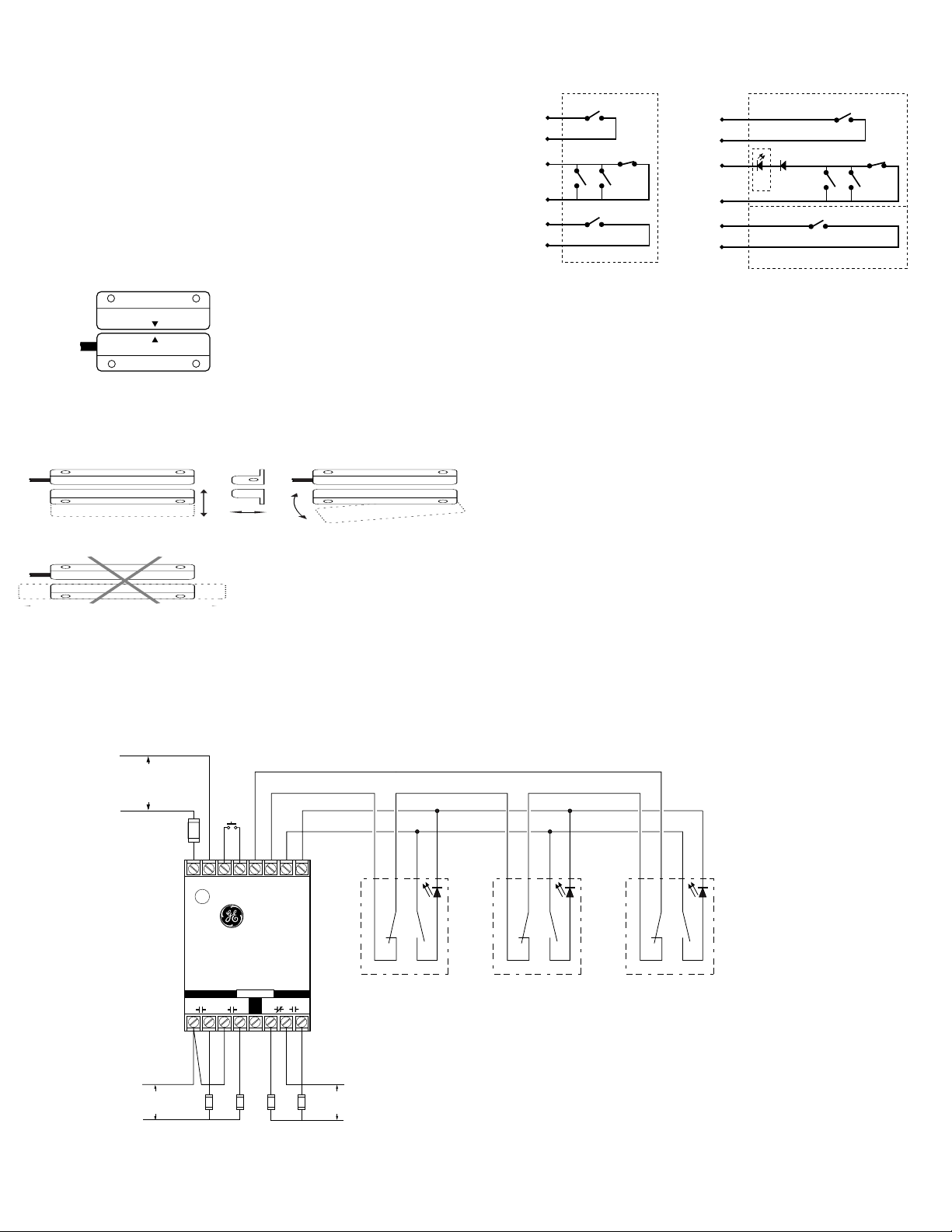
1. Position the switch and actuator so the labels are reading in the same direction
(See Figure 1.)
2. Mount the switch on the stationary frame of the machine and mount the actuator
on the moveable guard, door or gate. Keep the switch and actuator within the
listed sense range. (See Ordering Information.) See Figure 2 for recommended
mounting configurations.
3. Mounting on a ferrous material will effect the sense range a minimum of 50%.
However, a 1/4" non-ferrous spacer positioned under the magnet and/or switch
should restore most of the lost sense range.
4. For best protection against operator defeat, mount with non-removable screws,
bolts or nuts. See ordering information for details.
5. Caution! When not used with a Sentrol INT relay particular care must be taken to
determine the actual load of the switch circuit. High voltage transients from coils,
motors, contactors and solenoids must be considered. Transient protection, such
as back-to-back zener diodes (TransZorb
such loads to ensure that maximum ratings of the switch are not exceeded. Not
recommended to be used with tungsten filament loads because of high current
inrush surges. Line capacitance and load capacitance must be considered.
®
) or an RC network, is recommended for
301-BLT-12(J)(K)
301-B3T-06(J)
301-B3T-12(J)
301-B3T-20J
301-B3T-12J-NH
301-B3T-25J-NH
301-B3LT-12(J)(K)
continued
Page 2
Excessive line capacitance can be caused by cable lengths over 50' when using a
maximum 48 VAC. A resistor can be added in series to limit the inrush current
(at least 48 ohms for 24 Volt applications).
The resistor can be added in series just before the load.
The voltage drop and the power rating of the resistor must be considered.
Voltage drop = I•R;
2
Watts = I
•R (I = maximum continuous current of the load).
6. When mounting the switch on an ungrounded machine, ground the switch housing
by connecting your ground lead to one of the switch mounting screws.
Figure 1
CIR.1
CIR.2
CIR.3
BLK
WHT
BLUE
RED
BRN
ORG
Circuits*
without LED
S1
S2 S3
S5
Circuits*
with optional LED
BLK
CIR.
1
WHT
S4
CIR.
CIR.
2
3
BLUE
RED
BRN
ORG
D1
D2
S1
Optional LED
S2 S3
S5
S4
Actuator
Switch
sensing face
sensing face
S1,S5 Normally open reed switch, closed when actuator is within 0.6"
S2, S3 Normally open reed switches, will close if misaligned or tampered with a
standard magnet
S4 Biased closed reed switch, open when actuator is between 0.3" and 0.6"
*Circuits shown with magnet actuator away from switch.
Mounting Configurations
Figure 2
Perpendicular
Actuation
Best Best
Door
Actuation
Pivot Actuation
Good
Parallel Actuation
Not Recommended
N.O. circuit: Black and white wires.
N.C. biased tamper circuit: Red and blue wires.
N.O. monitor circuit: Orange and brown wires.
The parallel actuation can result in on/off/on signal if the actuator passes by the
switch rather than coming to rest in proximity to it. This is NOT a recommended
configuration for safety interlock applications.
Wiring Diagram for Category 3
Inputs shown with safety gates/guards in closed position. One Series 300-BT GuardSwitch™ required for each safety gate.
(–)
INT-03-230: 230V AC
INT-03-120: 120V AC
INT-03-024: 24V DC
(+)
Required Fast or
Slow-Acting Fuse:
(250V, 5x20 mm F)
INT-03-230: 40mA
INT-03-120: 80mA
INT-03-024: 1/4A
RESET
L1 L2 1 2 X1 X2 Y1 Y2
–
+
N.O. N.C.
W
B
H
L
T
K
Series Circuit
R
B
E
L
D
U
R
W
H
T
B
B
E
L
L
D
U
K
Parallel Circuit
R
W
B
E
H
L
D
T
K
B
L
U
Required Fast or SlowActing Fuses: 4A (250V,
5x20 mm F
GE Security Industrial
230 VAC
60 VDC
Safety Monitor Relay
INT-03
SAFE AUX.
A
BCD
LOADS
OUTPUTS
EFG
GuardSwitchTM Series 300
*300-BLT-
*Or other DPST GuardSwitch
(See the 300-BT Series installation instructions)
Note – The LED on the BLT model will be ON when the guard is open
Fuses: 1 A (250 v)
Multiple DPST GuardSwitches – Shown with actuators in position, all guards closed.
120 VAC
30 VDC
The L.E.D of the BLT model will be on when the guard is open. If multiple guards
are open, L.E.D will be dimmer. The maximum number of GuardSwitches that can
be used is 50, although troubleshooting and line resistance must be considered.
(Do not exceed 30 Ohms of combined contact and line resistance. Each GuardSwitch
will have less than 0.5 Ohms of resistance.)
*300-BLT-
*300-BLT-
Page 3
CE Compliance Information
These switches are TUV certified for CE applications only when used with the INT
Safety Monitor Relays. See Risk Category 3 and Category 4 wiring diagrams above.
European Directives
Machinery Directive (89/392/EEC)
EMC Directive (89/336/EEC)
Low Voltage Directive (73/23/EEC)
Specific European Standards
EN60204-1 Safety of electrical equipment of
industrial machines
EN292 Part 1, 2 Safety of Machinery, basic
Declaration of Conformity
available upon request.
terminology,
technical principles
EN954-1 Risk Assessment Category 3 or 4 depending
on wiring method, see diagrams
EN55081-2 Electromagnetic Emissions
EN50082-2 Electromagnetic Immunity
EN1088 Interlocking Devices
EN947-5-3 Control Circuit Devices
EN50178 Safety of Electrical Equipment
IEC 664-1 Insulation requirements
IEC 68, part 2-1, 2-2, 2-3, 2-8, 2-14, 2-27, 2-30
General Specifications
Enclosure 304 Folded Stainless steel
Temperature Range -40°F to 180°F (-40°C to 80°C)
Environmental Hermetically Sealed Contact Switch
Encapsulated in Polyurethane
NEMA Rating 1, 2, 4, 4X, 5, 12, 12K
Protection Class IP 66
Response Time 1 msec (5.4VA); 10 msec (150VA)
Individual circuits The two circuits do not switch
simultaneously, and depend on
the speed of the guard closure.
Based on closure speed of 1' per
second and a gap of 1/8", a delay
less than 50 msec is typical.
Life Cycles 100,000 Under Full Load;
Up to 200,000,000 Under Dry Circuit
Lead Types/O.D. 18/4 SJTOW (K)/0.34" (0.86cm)
22/4 PVC Jacketed (J)/0.19" (0.48cm)
22/6 PVC Jacketed (J)/0.21" (0.53cm)
UL/CSA All Models
File E 122942
LR89176
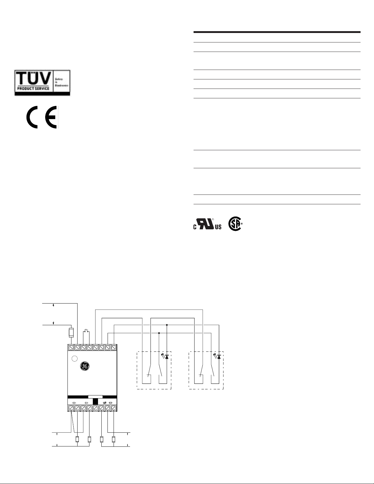
Wiring Diagram for Category 4
Inputs shown with safety gate/guard in closed position. Two Series 300-BT GuardSwitches™ with one INT relay are required for each safety gate.
When first applying the INT Safety Monitor Relay, the inputs must be cycled to check for proper operation before the output contacts close. To cycle the inputs, the guard must be
opened and then closed. This start-up test is sufficient; however, we recommend that the proper operation of the switches and relay be checked at least every 24 hours.
(–)
INT-03-230: 230V AC
INT-03-120: 120V AC
INT-03-024: 24V DC
(+)
Required Fast or
Slow-Acting Fuse:
(250V, 5x20 mm F)
INT-03-230: 40mA
INT-03-120: 80mA
INT-03-024: 1/4A
Required Fast or
Slow-Acting
Fuses: 4A (250V,
5x20 mm F
230 VAC
60 VDC
LOADS
RESET
L1 L2 1 2 X1 X2 Y1 Y2
–
+
Safety Monitor Relay
INT-03
SAFE AUX.
A
BCD EFG
N.O. N.C.
OUTPUTS
W
H
T
*Or other DPST GuardSwitch
(See the 300-BT Series
installation instructions)
120 VAC
30 VDC
R
B
B
E
L
L
D
U
K
*300-BLT-
Note – The LED on the BLT model
will be ON when the guard is open
Fuses: 1A (250V)
W
H
T
B
L
K
*300-BLT-
R
B
E
L
D
U
GE Security Industrial
GuardSwitchTM Series 300
Page 4

Electrical Specifications applies to all models
CIRCUIT NUMBER CIRCUIT CONTACT LOAD SWITCHING SWITCHING
TYPE CONFIGURATION RATING VOLTAGE CURRENT
1 Switch: S1 N.O. 40W/VA 48VAC/VDC 1.0ADC, 0.7AAC
2 Tamper: S2, S3, S4 N.C. 10W/VA 48VAC/VDC 0.3A
2 w/optional LED: D1 N.C. 0.1–1.4W 48VDC(3V drop) 30mA
3 Monitor: S5 N.O. 10W/VA 48VAC/VDC 0.3ADC, 0.3AAC
Ordering Information
PART NUMBER
1
301-BT-06(J)(K) DPST: 1 N.O., 1 N.C. 0.3"(0.8cm) 0.6"(1.5cm) 1.2"(3.0cm) 6' (1.8m)
301-BT-06J-NH
4
301-BT-12(J)(K) DPST: 1 N.O., 1 N.C. 0.3"(0.8cm) 0.6"(1.5cm) 1.2"(3.0cm) 12' (3.6m)
301-BT-12J-NH
301-BT-15J-NH
4
4
301-BT-20J DPST: 1 N.O., 1 N.C. 0.3"(0.8cm) 0.6"(1.5cm) 1.2"(3.0cm) 20' (6.1m)
301-BT-25J-NH
4
301-BLT-06(J)(K) DPST: 1 N.O., 1 N.C. w/LED 0.3"(0.8cm) 0.6"(1.5cm) 1.2"(3.0cm) 6' (1.8m)
301-BLT-12(J)(K) DPST: 1 N.O., 1 N.C. w/ LED 0.3"(0.8cm) 0.6"(1.5cm) 1.2"(3.0cm) 12' (3.6m)
301-B3T-06J TPST: 2 N.O., 1 N.C. 0.3"(0.8cm) 0.6"(1.5cm) 1.2"(3.0cm) 6' (1.8m)
301-B3T-12J TPST: 2 N.O., 1 N.C. 0.3"(0.8cm) 0.6"(1.5cm) 1.2"(3.0cm) 12' (3.6m)
301-B3T-20J TPST: 2 N.O., 1 N.C. 0.3"(0.8cm) 0.6"(1.5cm) 1.2"(3.0cm) 20' (6.1m)
301-B3T-12J-NH
301-B3T-25J-NH
4
4
301-B3LT-12(J)(K) TPST: 2 N.O., 1 N.C. w/ LED 0.3"(0.8cm) 0.6"(1.5cm) 1.2"(3.0cm) 12' (3.6m)
CONTACT
2
SENSE RANGE
3
SENSE RANGE
3
BREAK LEAD LENGTH
CONFIGURATION MINIMUM MAXIMUM RANGE NOMINAL
DPST: 1 N.O., 1 N.C. 0.6"(1.5cm) 1.2"(3.0cm) 6' (1.8m)
DPST: 1 N.O., 1 N.C. 0.3"(0.8cm) 0.6"(1.5cm) 1.2"(3.0cm) 12' (3.6m)
DPST: 1 N.O., 1 N.C. 0.3"(0.8cm) 0.6"(1.5cm) 1.2"(3.0cm) 15' (4.6m)
DPST: 1 N.O., 1 N.C. 0.3"(0.8cm) 0.6"(1.5cm) 1.2"(3.0cm) 25' (7.5m)
TPST: 2 N.O., 1 N.C. 0.3"(0.8cm) 0.6"(1.5cm) 1.2"(3.0cm) 12' (3.6m)
TPST: 2 N.O., 1 N.C. 0.3"(0.8cm) 0.6"(1.5cm) 1.2"(3.0cm) 25' (7.5m)
Accessories
PART NUMBER TAMPER PROOF SCREWS & SCREWDRIVER
1953 #6 x 3/4"L Tampruf Roundhead Screw
1954 #8 x 1-1/2"L Tampruf Roundhead Screw
1955 Tampruf Screwdriver
1956 Tampruf 1/4" Drive Bit for #6 and #8 screws
Warning— Each electrical rating is an individual maximum and cannot be exceeded!
1
The part numbers 301 and 303 are the same in all respects except the cable exits, 301 left and 303 right. Not all models are available in 303.
2
Configuration with actuator away from the switch
3
Proximity of ferrous materials usually reduces sense range — typically by 50%. The shape and type of material cause a wide diversity of effects.
Testing is required to determine actual sense range for specific applications.
4
The NH version does not have a minimum sense range.
GE Security
Industrial
©2004 GE Security Industrial. GE Security Industrial reserves the right to change specifications without notice.
I-3706-0204 13924 Rev C
 Loading...