

GE GFMN100ELWW Use And Care Manual
www.GEAppliances.ca
Safety Instructions 2-5
Installation Instructions 6-21
Electric Dryer
Gas Dryer
Rough-In Dimensions
Operating Instructions 22-38
Control Panels
Cycle Options
Dryer Features
Loading and Using the Dryer 28-29
Reversing the Door
Venting the Dryer
Stacking
Troubleshooting Tips 39-41
Consumer Support 42-44
Warranty
Consumer Support
Dryers
• • • • • • • • • • • • • •
• • • • • • • • • • • • • • • • •
• • • • • • •
• • • • • • • • • • • • • •
• • • • • • • • • • • • • • •
• • • • • • • • • • • • • •
• • • • • • • • • •
• • • • • • • • • • •
• • • • • • • • • • • • • • • • • • •
• • • • • • • • • • • • • • • • • • •
• • • • • • • • • •
6-12
13-20
21
22-24
25-26
27
30-33
34
35-38
42
44
Use and Care
With Installation Instructions.
Note to Consumer:
This product was verified to be
in excellent condition when it left
our manufacturing facility. If it
has been damaged during transit
or installation, please report that
damage immediately to the Retail
.desahcrup saw ti erehw teltuO
Although your warranty covers
manufacturing defects in material
or workmanship, it does not
include coverage for delivery
damage. Please refer to your
warranty section for specific
information about warranty terms
and conditions.
Write the model and serial
numbers here:
Model#
Serial #
They are on the label on the
front of the dryer behind the
door.
500A422P006 Rev.0
IMPORTANT SAFETY INFORMATION
READ ALL INSTRUCTIONS BEFORE USING
WARNING!
For your safety, the information in this manual must be followed to minimize the risk
of re or explosion, electric shock, or to prevent property damage, personal injury, or
Safety Instructions
death.
Do not store or use gasoline or other
ammable vapors and liquids in the
vicinity of this or any other appliance.
Installation and service must be
performed by a qualied installer,
service agency or the gas supplier.
WHAT TO DO IF YOU SMELL GAS:
Do not try to light a match, or cigarette,
1
or turn on any gas or electrical
appliance.
Do not touch any electrical switch; do
2
not use any phone in your building.
Clear the room, building or area of all
3
occupants.
Immediately call your gas supplier
4
from a neighbor’s phone. Follow the
gas supplier’s instructions carefully.
If you cannot reach your gas supplier,
5
call the re department.
Operating Instructions Installation InstructionsTroubleshooting Tips
Consumer Support
2
www.GEAppliances.ca
This dryer must be properly installed and located in accordance with the Installation Instructions before
it is used, present in this manual.
Properly ground dryer to conform to all governing
codes and ordinances. Follow details in
Installation Instructions section.
Install or store where it will not be exposed to
temperatures below freezing or exposed to the
weather.
Connect to a properly rated, protected and sized
power supply circuit to avoid electrical overload.
Remove the protective lm from both the control
panel and the door.
Remove all sharp packing items and dispose of all
shipping materials properly.
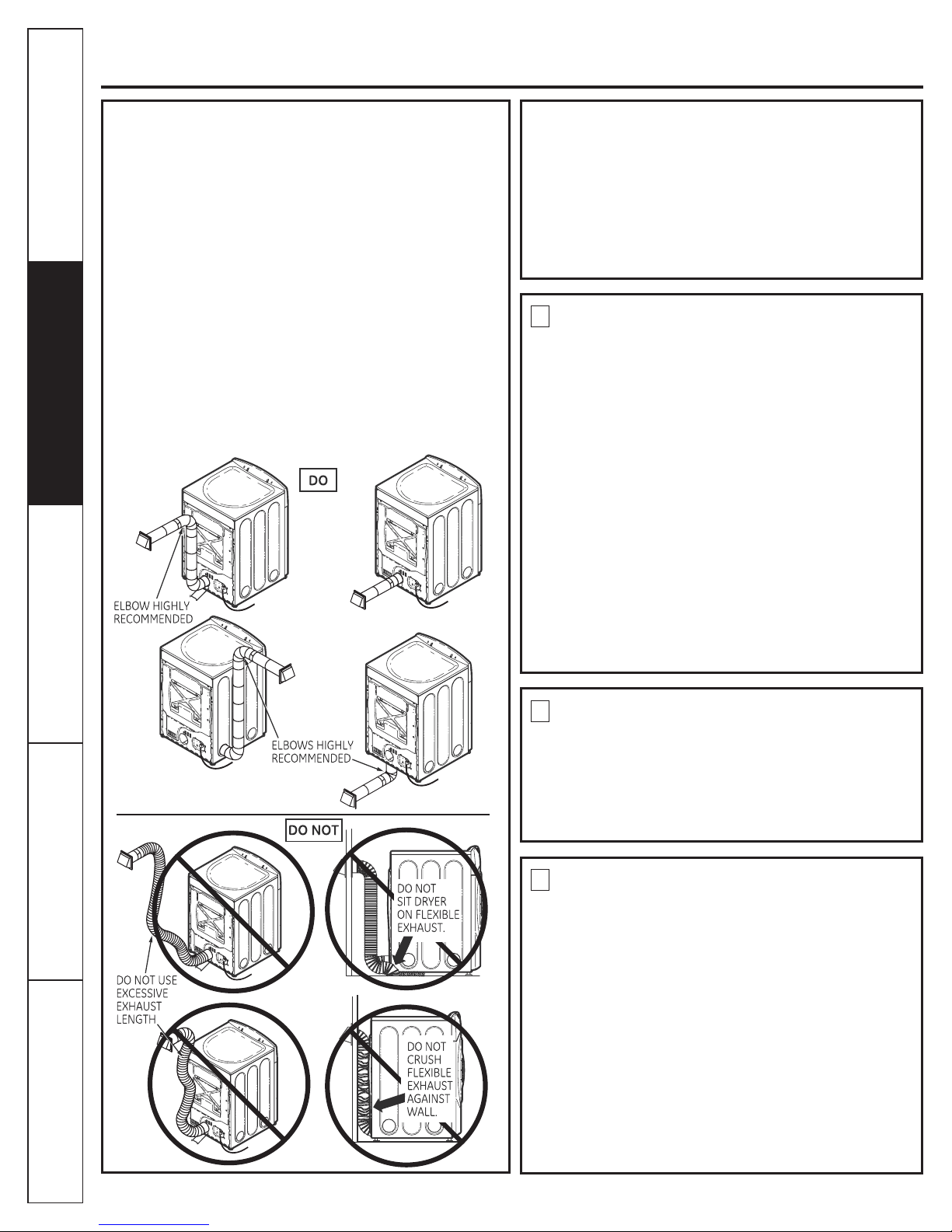
Do not remove the vent protector from the back
of the dryer. Pull the protector out and down to its
lowest position and connect the exhaust duct to
the dryer. The lowered protector will prevent the
duct from getting crushed.
Dryers MUST be exhausted to the outside to
prevent large amounts of moisture and lint from
being blown into the room.
Use only rigid metal or exible metal 10 cm (4”)
diameter ductwork inside for exhausting to the
outside.
USE OF PLASTIC OR OTHER COMBUSTIBLE
DUCTWORK CAN CAUSE A FIRE. PUNCTURED
DUCTWORK CAN CAUSE A FIRE IF IT COLLAPSES
OR BECOMES OTHERWISE RESTRICTED IN USE
OR DURING INSTALLATION.
1
2
For complete details, follow the Installation
Instructions.
Exhaust/Ducting:
PROPER INSTALLATION
Safety Instructions
Installation Instructions
Operating Instructions
Troubleshooting Tips
Consumer Support
3
IMPORTANT SAFETY INFORMATION
READ ALL INSTRUCTIONS BEFORE USING
WARNING!
YOUR LAUNDRY AREA
Keep the area underneath and around your
Safety Instructions
appliances free of combustible materials (lint,
paper, rags, etc), gasoline, chemicals, and other
ammable vapors and liquids.
Keep the oor around your appliances clean and
dry to reduce the possibility of slipping.
Close supervision is necessary if this appliance is
used near children. Do not allow children to play
on, with or inside this or any other appliance.
WHEN USING YOUR DRYER
Never reach into the dryer while the drum is
moving. Before loading, unloading or adding
clothes, wait until the drum has completely
stopped.
Clean the lint lter before each load to prevent
lint accumulation inside the dryer or in the room.
DO NOT OPERATE THE DRYER WITHOUT THE LINT
FILTER IN PLACE.
Do not wash or dry articles that have been
cleaned in, washed in, soaked in or spotted with
combustible or explosive substances (such as
wax, oil, paint, gasoline, degreasers, dry-cleaning
solvents, kerosene, etc.) which may ignite or
Operating Instructions Installation InstructionsTroubleshooting Tips
explode. Do not add these substances to the
wash water. Do not use or place these substances
around your washer or dryer during operation.
Do not place items exposed to cooking oils in your
dryer. Items contaminated with cooking oils may
contribute to a chemical reaction that could cause
a clothes load to catch re.
Any article on which you have used a cleaning
solvent or that contains ammable materials (such
as cleaning cloths, mops, towels used in beauty
salons, restaurants or barber shops, etc.) must not
be placed in or near the dryer. There are many
highly ammable items used in homes such as
acetone, denatured alcohol, gasoline, kerosene,
some household cleaners, some spot removers,
turpentines, waxes, wax removers and products
containing petroleum distillates.
Keep all laundry aids (such as detergents,
bleaches, etc.) out of the reach of children,
preferably in a locked cabinet. Observe all
warnings on container labels to avoid injury.
Never climb on or stand on the dryer top.
The laundry process can reduce the ame
retardancy of fabrics. To avoid such a result,
carefully follow the garment manufacturer’s care
instructions.
Do not dry articles containing rubber, plastic,
foam or similar materials such as padded bras,
tennis shoes, galoshes, bath mats, rugs, bibs, baby
pants, plastic bags, pillows, etc., that may melt
or burn. Some rubber materials, when heated,
can under certain circumstances produce re by
spontaneous combustion.
Do not store plastic, paper or clothing that may
burn or melt on top of the dryer during operation.
Garments labeled Dry Away from Heat or Do not
Tumble Dry (such as life jackets containing kapok)
must not be put in your dryer.
Do not dry berglass articles in your dryer. Skin
irritation could result from the remaining particles
that may be picked up by clothing during
subsequent dryer uses.
To minimize the possibility of electric shock,
unplug this appliance from the power supply or
disconnect the dryer at the building’s distribution
panel by removing the fuse or switching off
the circuit breaker before attempting any
maintenance or cleaning (except the removal
and cleaning of the lint lter). NOTE: Pressing
START, PAUSE or POWER does NOT disconnect the
appliance from the power supply.
Consumer Support
4

WHEN USING YOUR DRYER (cont.)
WHEN NOT USING YOUR DRYER
READ AND FOLLOW THIS SAFETY INFORMATION CAREFULLY.
SAVE THESE INSTRUCTIONS
Safety Instructions
www.GEAppliances.ca
Never attempt to operate this appliance if it is
damaged, malfunctioning, partially disassembled,
or has missing or broken parts, including a
damaged cord or plug.
The interior of the machine and the exhaust duct
connection inside the dryer should be cleaned at
least once a year by a qualied technician. See the
Loading and Using the Dryer section.
If yours is a gas dryer, it is equipped with an
automatic electric ignition and does not have a
pilot light. DO NOT ATTEMPT TO LIGHT WITH A
MATCH. Burns may result from having your hand
in the vicinity of the burner when the automatic
ignition turns on.
Grasp the plug rmly when disconnecting this
appliance to avoid damage to the cord while
pulling. Place the cord away from trafc areas so
it will not be stepped on, tripped over or subjected
to damage.
You may wish to soften your laundered fabrics
or reduce the static electricity in them by using
a dryer-applied fabric softener or an anti-static
conditioner. We recommend you use either a
fabric softener in the wash cycle, according
to the manufacturer’s instructions for those
products, or try a dryer-added product for which
the manufacturer gives written assurance on
the package that their product can be safely
used in your dryer. Service or performance
problems caused by use of these products are
the responsibility of the manufacturers of those
products and are not covered under the warranty
to this appliance.
Before discarding a dryer, or removing it from
service, remove the dryer door to prevent children
from hiding inside.
Do not tamper with controls.
Installation Instructions
Operating Instructions
Do not attempt to repair or replace any part of
this appliance or attempt any servicing unless
specically recommended in this Owner’s Manual
or in published user-repair instructions that you
understand and have the skills to carry out.
Troubleshooting Tips
Consumer Support
5
Electric Dryer
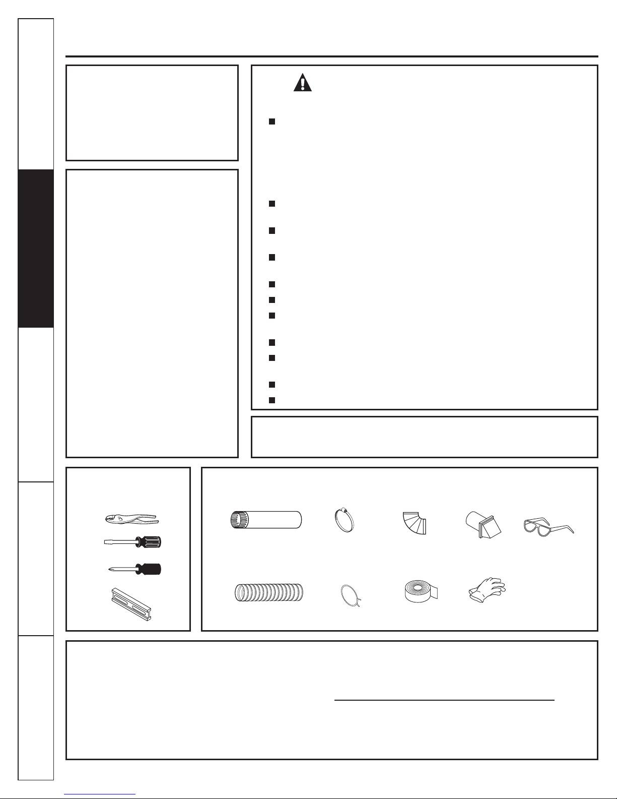
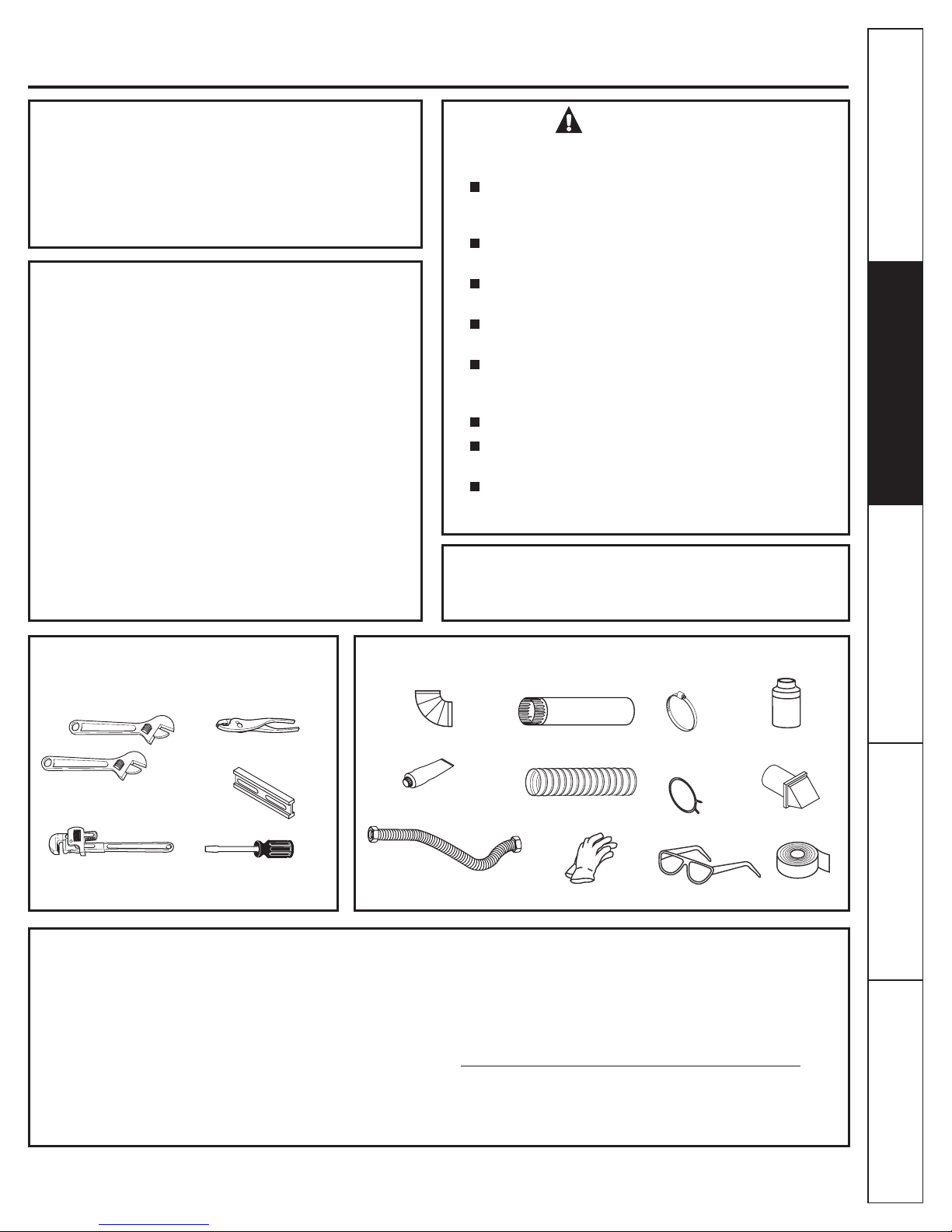
TOOLS YOU
WILL NEED
MATERIALS YOU
WILL NEED
SLIP JOINT PLIERS
LEVEL
FLAT BLADE SCREWDRIVER
1O cm (4 in.) DIA.
METAL DUCT (RECOMMENDED)
1O cm (4 in.)
METAL ELBOW
EXHAUST
HOOD
DUCT TAPE
GLOVES
SAFETY GLASSES
1O cm (4 in.) DUCT
CLAMPS (2)
OR
10 cm (4 in.) SPRING
CLAMPS (2)
1O cm (4 in.) DIA. FLEXIBLE METAL
DUCT (IF NEEDED)
PHILLIPS SCREWDRIVER
NOTE: Installation and service of this dryer requires basic mechanical and
electrical skills. It is your responsibility to contact a qualified installer to make
the electrical connections.
Use only rigid metal or flexible metal 4-in. diameter ductwork for exhausting to
the outdoors. Never use plastic or other combustible, easy-to-puncture
ductwork. Do not install a clothes dryer with flexible plastic venting materials. If flexible (foil type) duct is installed, it must be a UL or CSA listed flexible
metal transition duct suitable for use with clothes dryers. Flexible venting
materials are known to collapse, be easily crushed, and trap lint. These
conditions will obstruct clothes dryer airflow and increase the risk of fire.
This dryer must be exhausted to the outdoors.
Clothes dryer installation must be performed by a qualified installer.
Install the clothes dryer according to the manufacturer’s instructions and local
codes.
Inspect the dryer exhaust outlet and straighten the outlet walls if they are bent.
Do not allow children on or in the appliance. Close supervision of children is
necessary when the appliance is used near children.
Install the dryer where the temperature is above 10° C (50°F) for satisfactory
operation of the dryer control system.
Do not install or store appliance in an area where it will be exposed to water
and/or weather.
This appliance must be properly grounded and installed as described in these
instructions.
To reduce the risk of severe injury or death, follow all installation instructions.
Save these instructions.
IMPORTANT - Save these
instructions for local inspector’s use.
IMPORTANT - Observe all
Note to Installer - Be sure to leave these
instructions with the customer.
Note to Customer - Keep these instructions with your Use and Care Book for
future reference.
governing codes and ordinances.
(comes with individual installation
Safety Instructions
PEDESTALS FOR DRYERS
instructions)
Available models: -SBSD227F
-SBSD137H
-SBSD107H
BEFORE
YOU BEGIN:
Read these instructions completely
and carefully.
Before the old dryer is removed from
service or discarded, remove the dryer
door.
Service information and the wiring
diagram are located in the control
console.
WARNING! - RISK OF FIRE
FOR YOUR SAFETY:
Operating Instructions Installation InstructionsTroubleshooting Tips
Step 1 Prepare the area and exhaust for installation of
new dryer (see section 1).
Step 2 Check and ensure the existing external exhaust is
clean (see section 1) and meets attached
installation specifications (see section 3).
Step 3 Remove the foam shipping pads (see section 1).
Step 4 Move the dryer to the desired location.
Step 5 Connect the power supply (see section 2).
Step 6 Connect the external exhaust (see section 4).
Consumer Support
6
Step 7 Level your dryer (see section 5).
Step 8 Check the operation of the power supply and venting.
Step 9 Place the owners Use and Care in a location
where it will be noticed by the owner.
For alcove or closet installation, see section 6.
For bathroom or bedroom installation, see section 7.
For mobile or manufactured home see, section 8.
For side or bottom exhaust, see section 9.
Electric Dryer
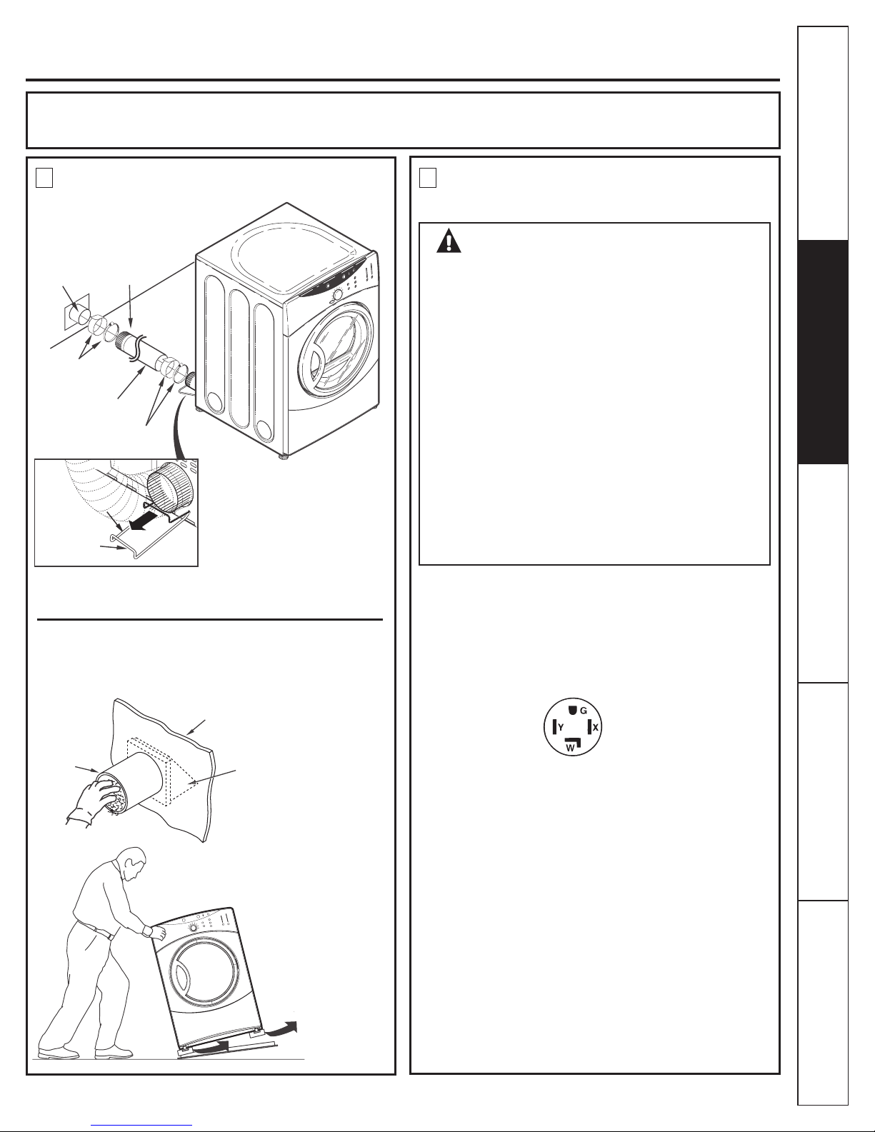
Pull the vent protection bracket
out until it stops, and let it rest on
the oor. The bracket prevents
the unit from moving too close
to the wall and crushing the
rear vent. Prolong by adding a
DASHED FLEXIBLE duct.
Tilt the dryer sideways
and remove the foam
shipping pads by
pulling at the sides
and breaking them
away from the dryer
legs. Be sure to
remove all of the
foam pieces around
the legs.
Minimum Clearance Other Than Alcove or Closet Installation
Minimum clearance to combustible surfaces and for air opening are: 0 cm (0 in.) clearance both sides and 2.5 cm (1 in.) rear.
Consideration must be given to provide adequate clearance for installation and service.
1 2
REMOVING LINT FROM WALL EXHAUST
OPENING & FOAM REMOVAL FROM
DRYER LEGS
INTERNAL DUCT
OPENING
WALL
EXTERNAL
DUCT
OPENING
DISCONTINUITY
ON DUCT
DUCT TAPE OR
DUCT CLAMP
VENT
PROTECTION
BRACKET
DUCT TAPE OR
DUCT CLAMP
10 cm (4 in.)
METAL DUCT
CHECK THAT EXHAUST HOOD
DAMPER OPENS AND CLOSES
FREELY.
TYPICAL 30 AMP
RECEPTACLE FOR DRYER
DO NOT USE AN EXTENSION CORD OR AND
ADAPTER PLUG WITH THIS APPLIANCE.
Dryer must be electrically grounded in accordance
with local codes and ordinances. Installation must be
in accordance with the current CSA C22.1 Canadian
Electrical code part 1. Improper connection of the
equipment-grounding conductor can result in an electric
shock. Check with a qualied electrician or service
representative or personnel if you are in doubt as to
whether the appliance is properly grounded.
Do not modify the plug provided with the appliance: if it
will not t the outlet, have a proper outlet installed by a
qualied electrician.
This dryer must be connected to an individual branch
circuit, protected by the required time-delay fuses or
circuit breakers. The power supply must be of 120/240
volts, 60 Hz circuit with the wall receptacle as shown
below:
The power supply must be protected with 30 Amp fuses or
breakers. It must be well grounded and conform to local
codes.
This appliance must be grounded. In the event of malfunction
or breakdown, grounding will reduce the risk of electrical
shock by providing a path of least resistance for electrical
current. This appliance is equipped with a cord having an
equipment-grounding conductor and a grounding plug.
The plug must be plugged into an appropriate outlet that is
properly installed and grounded in accordance with all local
codes and ordinances.
www.GEAppliances.ca
PREPARING FOR INSTALLATION
OF NEW DRYER
ELECTRICAL CONNECTION
INFORMATION
Safety Instructions
TIP: Install your dryer before installing your washer.
This will allow better access when installing dryer exhaust.
WARNING - TO REDUCE THE RISK
OF FIRE, ELECTRICAL SHOCK AND
PERSONAL INJURY:
ELECTRICAL REQUIREMENTS
Installation Instructions
Operating Instructions
Troubleshooting Tips
GROUNDING INSTRUCTIONS
Consumer Support
7
Electric Dryer
EXHAUST INFORMATION
THIS DRYER COMES READY FOR REAR
EXHAUSTING. IF SPACE IS LIMITED, USE THE
INSTRUCTIONS IN SECTION 9 TO EXHAUST
DIRECTLY FROM THE SIDES OR BOTTOM OF
THE CABINET.
EXHAUST CONNECTION
STANDARD REAR EXHAUST
(Vented at floor level)
3 4
WARNING - TO REDUCE THE RISK
OF FIRE OR PERSONAL INJURY:
WARNING - IN CANADA AND IN THE U.S.,
THE REQUIRED EXHAUST DUCT DIAMETER IS
4 in (102mm). DO NOT USE DUCT LONGER THAN
SPECIFIED IN THE EXHAUST LENGTH TABLE.
Using exhaust longer than specified length will:
• Increase the drying times and the energy cost.
• Reduce the dryer life.
• Accumulate lint, creating a potential fire hazard.
The correct exhaust installation is YOUR RESPONSIBILITY.
Problems due to incorrect installation are not covered by
the warranty.
This dryer must be exhausted to the outdoors.
•
• Only rigid or flexible metal duct shall be used for
exhausting.
• Do not terminate exhaust in a chimney, a wall, a
ceiling, an attic, an enclosed floor (crawl space) or a
concealed space of a building. The accumulated
lint could create a fire hazard.
• Provide an access for inspection and cleaning of
the exhaust system, especially at turns. Inspect and
clean at least once a year.
• Never terminate the exhaust into a common duct
with a kitchen exhaust. A combination of lint and
grease could create a fire hazard.
• Do not obstruct incoming or exhausted air.
EXHAUST SYSTEM CHECKLIST
HOOD OR WALLCAP
• Terminate in a manner to prevent back drafts or entry of birds or other
wildlife. Termination should present minimal resistance to the exhaust
air flow and should require little or no maintenance to prevent clogging.
• Never install a screen in or over the exhaust duct. This could cause lint
build up, thus creating a fire hazard.
• Wall caps must be installed at least 30 cm (12 in.) above ground level or
any other obstruction with the opening pointed down.
• If roof vents or louvered plenums are used, they must be equivalent to
a 10 cm (4 in. ) dampened
wall cap in regard to resistance to air flow,
prevention of back drafts, and maintenance required to prevent clogging.
SEPARATION OF TURNS
For best performance, separate all turns by at least 1.2 m (4 ft.) of straight
duct, including distance between last turn and exhaust hood.
TURNS OTHER THAN 90º
• One turn of 45º or less may be ignored. Two 45º turns should be treated
as one 90º turn. Each turn over 45º should be treated as one 90º turn.
SEALING OF JOINTS
• All joints should be tight to avoid leaks. The male end of each section of
duct must point away from the dryer.
• Do not assemble the ductwork with fasteners that extend into the duct.
They will serve as a collection point for lint.
• Duct joints should be made air and moisture-tight by wrapping the
overlapped joints with duct tape.
• Horizontal runs should slope down toward the outdoors 1.2cm (1/2 in.) /ft.
INSULATION
Duct work that runs through an unheated area or is near air conditioning
should be insulated to reduce condensation and lint build-up.
If using flexible metal duct, please refer to page 10.
NOTE: WE STRONGLY RECOMMEND SOLID METAL EXHAUST
DUCTING. HOWEVER, IF FLEXIBLE DUCTING IS USED IT MUST BE
METAL NOT PLASTIC.
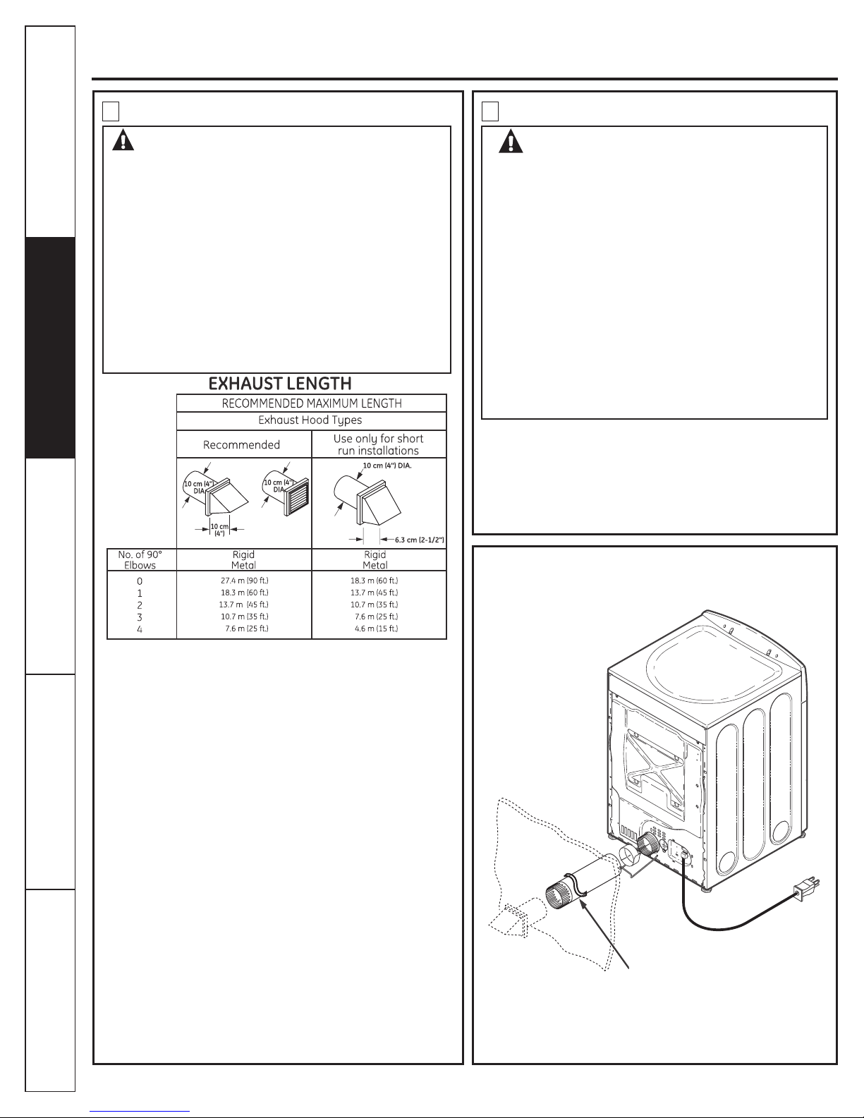
CUT THE METAL EXHAUST DUCT
(NOT SUPPLIED) TO THE PROPER
LENGTH.
For straight
line installation,
connect the dryer
exhaust to the
external exhaust
hood using duct
tape or clamp.
The MAXIMUM ALLOWABLE duct length and number of
bends of the exhaust system depends upon the type of duct,
number of turns, the type of exhaust hood (wall cap), and all
conditions noted below. The maximum exhaust length for
rigid metal duct is shown in the table below.
Safety Instructions
Operating Instructions Installation InstructionsTroubleshooting Tips
Consumer Support
8
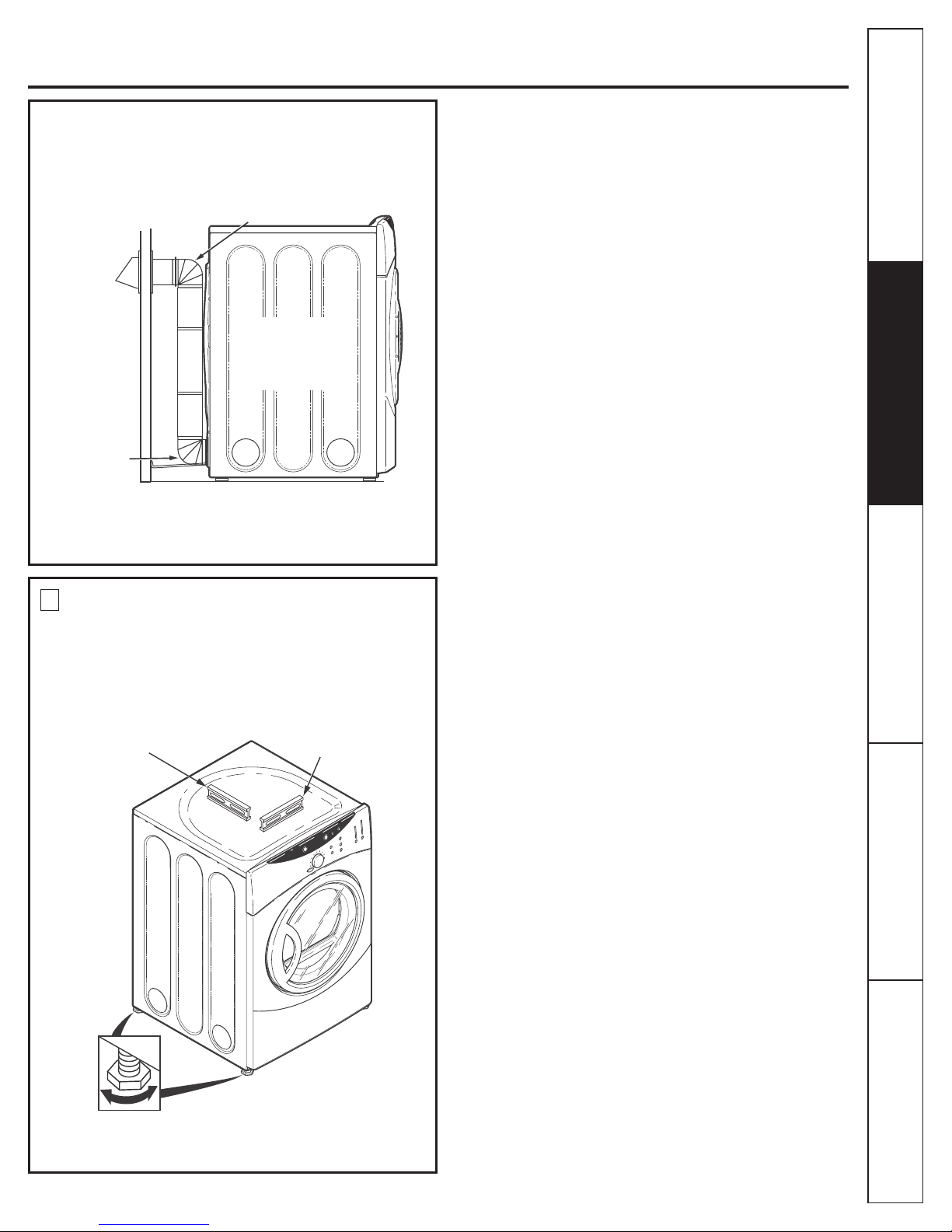
Electric Dryer
Stand the dryer upright near the nal location and
adjust the 4 leveling legs, at the corners, to ensure that
the dryer is level from side to side and front to rear.
ELBOW HIGHLY
RECOMMENDED
ELBOW HIGHLY
RECOMMENDED
RECOMMENDED
CONFIGURATION
TO MINIMIZE
EXHAUST
BLOCKAGE.
LEVEL
FRONT-TO-BACK
4 LEVELING
LEGS
LEVEL
SIDE-TO-SIDE
STANDARD REAR EXHAUST
(Vented above oor level)
Safety Instructions
www.GEAppliances.ca
Installation Instructions
NOTE: ELBOWS WILL PREVENT DUCT KINKING
AND COLLAPSING.
5
LEVELING AND STABILIZING YOUR
DRYER
Operating Instructions
Troubleshooting Tips
Consumer Support
9
Electric Dryer
USING FLEXIBLE METAL DUCTS EXHAUSTING
If rigid all-metal duct cannot be used, then flexible all-metal
ducting can be used, but it will reduce the maximum
recommended duct length. In special installations when it is
impossible to use only metal ducting, then UL-listed clothes dryer
flexible metal transition duct may be used as transition venting
between the dryer and wall connection only. The use of this
Safety Instructions
ducting will affect dry time.
If flexible transition duct is necessary, the following directions
must be followed.
•
In Canada and in the United States, only the foil-type flexible
ducts that comply with the Outline for Clothes Dryer Transition Duct Subject 2158A shall be used.
• Use the shortest length possible.
•
Total length of flexible metal duct shall not exceed 8 ft (2.4 m).
Stretch the duct to its maximum length to avoid kinks.
•
•
Do not crush or collapse the duct.
•
Extend vent protection bracket as described in step 1.
Never use transition duct inside the wall or inside the
•
dryer on page 2.
•
Avoid resting the duct on sharp objects.
• Venting must conform to local building codes.
A CLOTHES DRYER PRODUCES COMBUSTIBLE LINT. FOR
ALL INSTALLATIONS, THE DRYER MUST BE CONNECTED
TO AN EXHAUST TO THE OUTDOORS.
NOTE: MOBILE HOME, BEDROOM, BATHROOM, ALCOVE
OR CLOSET INSTALLATIONS MUST BE EXHAUSTED TO
THE OUTDOORS.
6
ALCOVE OR CLOSET INSTALLATION
• If your dryer is approved for installation in an alcove or closet,
it will be stated on a label on the dryer back.
• The dryer MUST be vented to the outdoors. See the EXHAUST
INFORMATION sections 3 & 4.
• Minimum clearance between dryer cabinet and adjacent walls
or other surfaces is:
0 in. either side
7.6 cm (3 in.) front and rear
• Minimum vertical space from floor to overhead cabinets,
ceiling, etc. is 109 cm (43 in.) without pedestal, 140 cm (55 in.)
with pedestal.
• Closet doors must be louvered or otherwise ventilated and
must contain a minimum of 387 sq. cm (60 sq. in.) of open area
equally distributed. If the closet contains both a washer and
a dryer, doors must contain a minimum of 774 sq. cm (120 sq.
in.) of open area equally distributed.
NOTE: WHEN THE EXHAUST DUCT IS LOCATED AT THE
REAR OF THE DRYER, MINIMUM CLEARANCE FROM THE
WALL IS 14 cm (5.5 IN.)
Operating Instructions Installation InstructionsTroubleshooting Tips
7
BATHROOM OR BEDROOM
INSTALLATION
• The dryer MUST be vented to the outdoors. See EXHAUST
INFORMATION section 3 & 4.
• The installation must conform with local codes or, in the
absence of local codes, with the current CSA C22.1 Canadian
Electrical code part 1.
8
MOBILE OR MANUFACTURED HOME
INSTALLATION
• Installation must conform to the current CAN/CSA Z240 MH
series Mobile Home Installation Codes.
• The dryer MUST be vented to the outdoors with the
termination securely fastened to the mobile home structure.
(See EXHAUST INFORMATION section 3 & 4.)
• The vent MUST NOT be terminated beneath a mobile or
manufactured home.
• The vent duct material MUST BE METAL.
• Do not use sheet metal screws or other fastening devices
which extend into the interior of the exhaust vent.
• See section 2 for electrical connection information.
Consumer Support
10
Electric Dryer
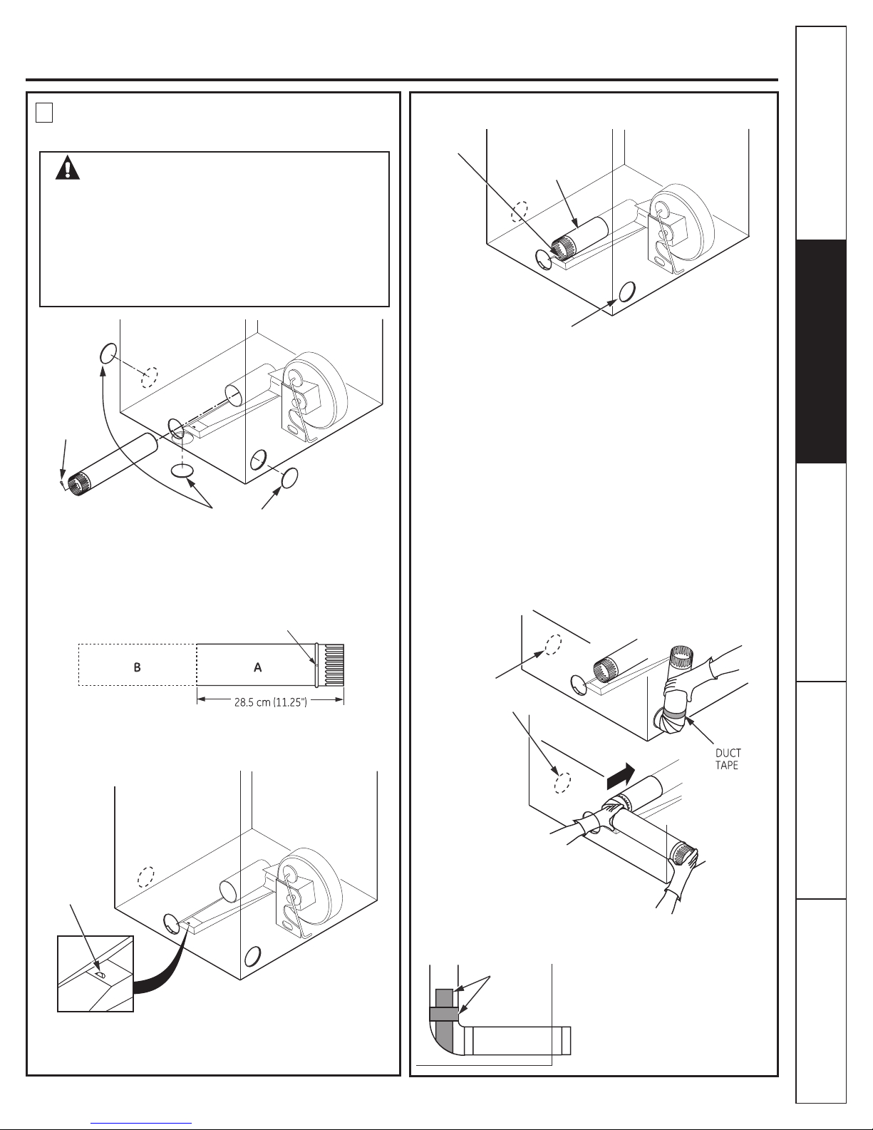
Detach and remove the bottom, right or left side knockout as
desired. Remove the screw inside the dryer exhaust duct and
save. Pull the duct out of the dryer.
Cut the duct as shown and keep portion A.
Through the rear opening, locate the tab in the middle of the
appliance base. Lift the tab to about 45º using a at blade
screwdriver.
Reconnect the cut portion (A) of the duct to the blower housing.
Make sure that the shortened duct is aligned with the tab in the
base. Use the screw saved previously to secure the duct in place
through the tab on the appliance base.
ADDING ELBOW AND DUCT FOR EXHAUST
TO LEFT OR RIGHT SIDE OF CABINET
• Preassemble 10 cm (4”) elbow with 10 cm (4”) duct. Wrap duct
tape around joint.
• Insert duct assembly, elbow rst , through the side opening and
connect the elbow to the dryer internal duct.
CAUTION: Be sure not to pull or damage the
electrical wires inside the dryer when
inserting the duct.
• Apply duct tape as shown on the joint between the dryer
internal duct and the elbow.
CAUTION:
Internal duct joints must be
secured with tape, otherwise
they may separate and cause
a safety hazard.
REMOVE
SCREW
AND SAVE.
REMOVE
DESIRED
KNOCKOUT
(ONE ONLY).
DUCT
TAPE
FIXING HOLE
BEND TAB
UP 45º
FIXING
HOLE
RIGHT OR
LEFT SIDE
EXHAUST
EXHAUST CAN BE
ADDED TO LEFT OR
RIGHT SIDE
PORTION “A”
9
DRYER EXHAUST TO RIGHT, LEFT OR
BOTTOM CABINET
WARNING - BEFORE PERFORMING
THIS EXHAUST INSTALLATION, BE SURE
TO DISCONNECT THE DRYER FROM ITS
ELECTRICAL SUPPLY. PROTECT YOUR
HANDS AND ARMS FROM SHARP EDGES
WHEN WORKING INSIDE THE CABINET.
BE SURE TO WEAR GLOVES.
www.GEAppliances.ca
ADDING NEW DUCT
Safety Instructions
Installation Instructions
Operating Instructions
TAB LOCATION
Troubleshooting Tips
Consumer Support
11
Electric Dryer
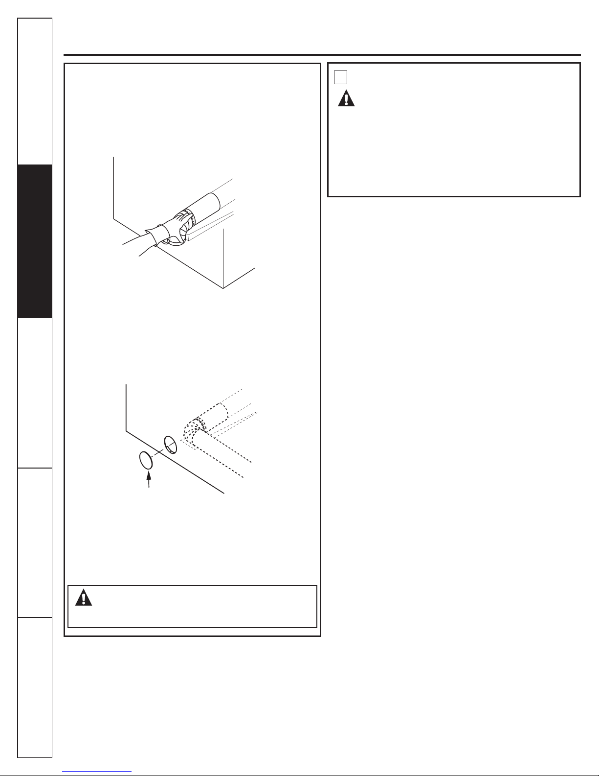
CAUTION:
Internal duct joints must be secured with tape,
otherwise they may separate and cause a
safety hazard.
ADDING COVER PLATE TO REAR OF
CABINET (SIDES AND BOTTOM EXHAUST)
Connect standard metal elbows and ducts to complete the
exhaust system. Cover back opening with a plate (Kit
WE1M454) available from your local service provider. Place
dryer in nal location.
WARNING - NEVER LEAVE THE BACK
OPENING WITHOUT THE PLATE. (Kit WE1M454)
SERVICING
10
WARNING - LABEL ALL WIRES PRIOR
TO DISCONNECTING WHEN SERVICING
CONTROLS. WIRING ERRORS CAN CAUSE
IMPROPER AND DANGEROUS OPERATION
AFTER SERVICING/INSTALLATION.
For servicing phone numbers for replacement parts, and other
information, refer to Owner’s Manual or visit our Web site.
PLATE
(KIT WE1M454)
DRYER EXHAUST TO RIGHT, LEFT OR
BOTTOM CABINET
• Insert the elbow through the rear opening and connect it to the
dryer internal duct.
• Apply duct tape on the joint between the dryer internal duct
Safety Instructions
and elbow, as shown on page 11.
Operating Instructions Installation InstructionsTroubleshooting Tips
Consumer Support
12
Gas Dryer
SLIP JOINT PLIERS
LEVEL
1O cm (4 in.) DIA.
METAL DUCT (RECOMMENDED)
1O cm (4 in.)
METAL ELBOW
EXHAUST HOOD
DUCT TAPE
GLOVES
SAFETY GLASSES
PIPE COMPOUND
8 in. PIPE WRENCH
10 in. ADJUSTABLE WRENCHES (2)
FLEXIBLE GAS LINE CONNECTOR
1O cm (4
in.) DUCT
CLAMPS (2)
1O cm (4 in.) DIA. FLEXIBLE METAL
DUCT (IF NEEDED)
SOAP SOLUTION FOR
LEAK DETECTION
FLAT BLADE SCREWDRIVER
Safety Instructions
www.GEAppliances.ca
PEDESTALS FOR DRYERS
(comes with individual installation instructions)
Available models: -SBSD227F
-SBSD137H
-SBSD107H
BEFORE YOU BEGIN:
Read these instructions completely and carefully.
IMPORTANT - Save these instructions for local
inspector’s use.
IMPORTANT - Observe all governing codes and
ordinances.
Note to Installer - Be sure to leave these instructions with the
customer.
Note to Customer - Keep these instructions with your Use
and Care Book for future reference.
Before the old dryer is removed from service or discarded,
remove the dryer door.
Service information and the wiring diagram are located in the
control console.
WARNING!
FOR YOUR SAFETY:
Use only rigid metal or exible metal 10 cm (4 in.) diameter
ductwork for exhausting to the outdoors. Never use plastic
or other combustible, easy-to-puncture ductwork.
This appliance must be properly grounded and installed as
described in these instructions.
Do not install or store appliance in an area where it will be
exposed to water and/or weather.
Verify and conform to local regulations before installing an
appliance in the garage.
Install the dryer where the temperature is above 10°
C (50°F) for satisfactory operation of the dryer control
system.
This dryer must be exhausted to the outdoors.
Inspect the dryer exhaust outlet and straighten the outlet
walls if they are bent.
Do not allow children on or in the appliance. Close
supervision of children is necessary when the appliance is
used near children.
NOTE: Installation and service of this dryer requires basic
mechanical and electrical skills. It is your responsibility
to contact a qualied installer to make the electrical
connections.
Installation Instructions
Operating Instructions
TOOLS YOU
WILL NEED
Step 1 Verify your gas installation (see section2).
Step 2 Prepare the area and exhaust for installation of
new dryer (see section 1).
Step 3 Check and ensure the existing external exhaust is
clean (see section 1) and meets attached
installation specications (see section 6).
Step 4 Remove the foam shipping pads (see section 1).
Step 5 Move the dryer to the desired location.
Step 6 Level your dryer (see section 8).
Step 7 Connect the gas supply (see section 3) and check
for leaks (see section 4)
Step 8 Connect the external exhaust (see section 7).
Step 9 Connect the power supply (see section 5).
Step 10 Check the operation of the power supply, gas
connections and venting.
Step 11 Place the Use and Care in a location where
it will be noticed by the owner.
For alcove or closet installation, see section 9.
For bathroom or bedroom installation, see section 10.
For mobile or manufactured home see, section 11.
MATERIALS YOU
WILL NEED
Troubleshooting Tips
Consumer Support
13
Gas Dryer
INTERNAL DUCT
OPENING
WALL
CHECK THAT EXHAUST HOOD
DAMPER OPENS AND CLOSES
FREELY.
WARNING!
WARNING - NEVER REUSE OLD
FLEXIBLE CONNECTORS.
The use of old exible connectors can cause leaks and
personal injury. Always use new exible connectors when
installing gas appliances.
DRYER GAS SUPPLY CONNECTION
• Installation must conform to local codes and ordinances,
or in their absence, the NCAN/CGA-B149, Natural Gas,
Installation.
• This gas dryer is equipped with a Valve & Burner Assembly
for use only with natural gas. Using conversion kit
WE25M43, your local service organization can convert this
dryer for use with propane (LP) gas. ALL CONVERSIONS
MUST BE MADE BY PROPERLY TRAINED AND QUALIFIED
PERSONNEL AND IN ACCORDANCE WITH LOCAL CODES
AND ORDINANCE REQUIREMENTS OF THE CAN/CGAB149.1 AND B149.2 INSTALLATION CODE.
• The dryer must be disconnected from the gas supply
piping system during any pressure testing of that system
at a test pressure in excess of 0.5 PSI (3.4 KPa).
• The dryer must be isolated from the gas supply piping
system by closing the equipment shut-off valve during any
pressure testing of the gas supply piping of test pressure
equal to or less than 0.5 PSI (3.4 KPa).
• A 0.3 cm (1/8-in.) National Pipe Taper thread plugged tapping,
accessible for test gauge connection, must be installed
immediately upstream of the gas supply connection to
the dryer. Contact your local gas utility should you have
questions on the installation of the plugged tapping.
• Supply line is to be 1.2 cm (1/2-in.) rigid pipe and equipped
with an accessible shut-off within 2 m (6 ft.) of, and in the
same room with, the dryer.
• Use pipe thread sealer compound appropriate for natural or
LP gas or use Teon tape.
• You must use with this dryer a exible metal connector listed
connector ANSI Z21.24 / CSA 6.10.
• Connect exible metal connector to dryer and gas supply.
• Open shut-off valve.
EXTERNAL
DUCT
OPENING
GAS
INLET
PIPE
CSA (AGA) APPROVED
NEW FLEXIBLE GAS
LINE CONNECTOR
TURN GAS
SHUT-OFF
VALVE TO THE
OFF POSITION.
DISCONNECT AND DISCARD OLD
FLEXIBLE GAS CONNECTOR AND
OLD DUCTING MATERIAL
DUCT
TAPE
DUCT
TAPE
VENT
PROTECTION
BRACKET
10 cm (4 in.) METAL DUCT
NPT MALE THREAD GAS SUPPLY
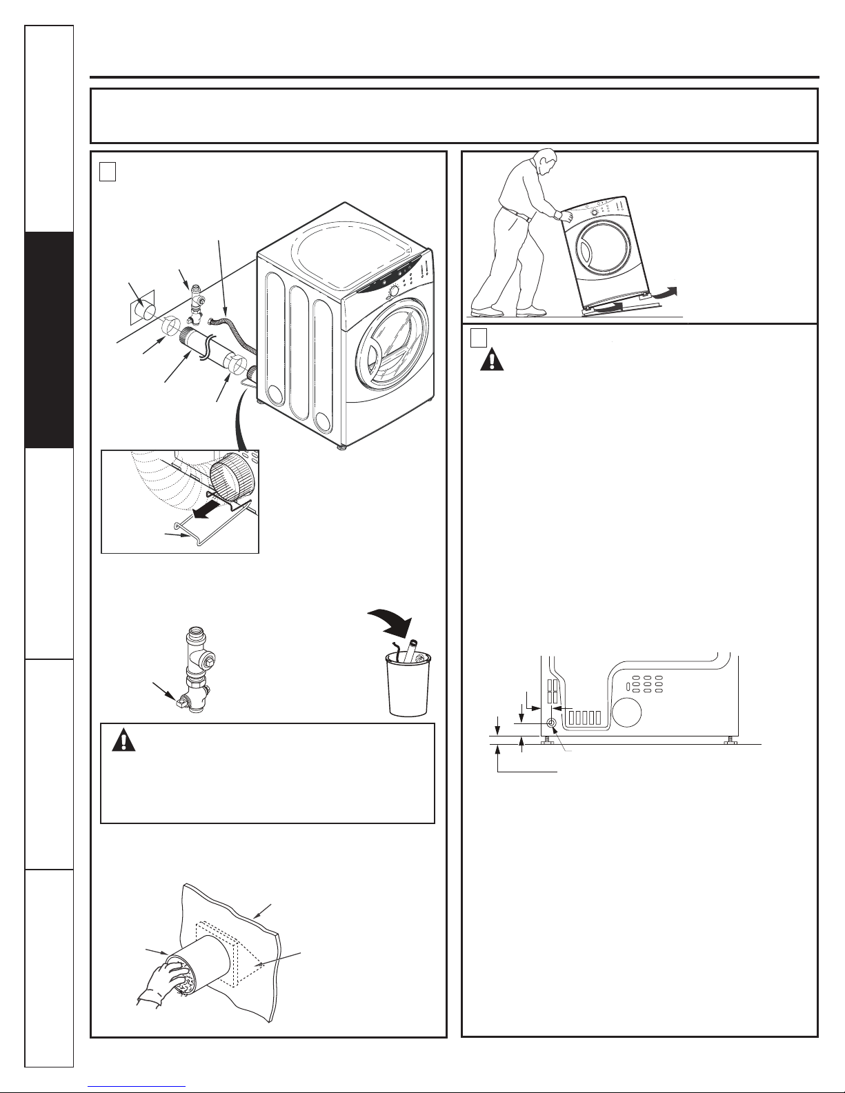
NOTE: Add to vertical dimension
the distance between cabinet
bottom to oor.
5 cm (2")
6.6 cm (2-5/8")
0.9 cm (3/8")
Minimum Clearance Other Than Alcove or Closet Installation
Minimum clearance to combustible surfaces and for air opening are: 0 cm (0 in.) clearance both sides and 2.5 cm (1 in.) rear.
Consideration must be given to provide adequate clearance for installation and service.
1
PREPARING FOR INSTALLATION
OF NEW DRYER
Safety Instructions
TIP: Install your dryer before installing your washer.
This will allow better access when installing dryer exhaust.
DISCONNECTING GAS
Operating Instructions Installation InstructionsTroubleshooting Tips
Pull the vent protection bracket
out until it stops, and let it rest on
the oor. The bracket prevents
the unit from moving too close
to the wall and crushing the
rear vent. Prolong by adding a
DASHED FLEXIBLE duct.
Tilt the dryer sideways
and remove the foam
shipping pads by pulling
at the sides and breaking
them away from the
dryer legs. Be sure to
remove all of the foam
pieces around the legs.
2
GAS REQUIREMENTS
REMOVING LINT FROM WALL EXHAUST
OPENING
Consumer Support
14
GAS SUPPLY
 Loading...