

GE RSTi-EP, GFK-2958E User Manual

RSTi-EP User Manual
GFK-2958E
November 2017

These instructions do not purport to cover all details or variations in equipment, nor to provide for every possible
contingency to be met during installation, operation, and maintenance. The information is supplied for
informational purposes only, and GE makes no warranty as to the accuracy of the information included herein.
Changes, modifications, and/or improvements to equipment and specifications are made periodically and these
changes may or may not be reflected herein. It is understood that GE may make changes, modifications, or
improvements to the equipment referenced herein or to the document itself at any time. This document is
intended for trained personnel familiar with the GE products referenced herein.
Public – This document is approved for public disclosure.
GE may have patents or pending patent applications covering subject matter in this document. The furnishing of
this document does not provide any license whatsoever to any of these patents.
GE provides the following document and the information included therin as-is and without warranty of any
kind, expressed or implied, including but not limited to any implied statutory warrany of merchantability or
fitness for particular purpose.
Revised: Nov 2017
Issued: Dec 2015
© 2015 - 2017 General Electric Company.
* Indicates a trademark of General Electric Company and/or its subsidiaries. All other
trademarks are the property of their respective owners.

Safety Symbol Legend
Warning
Indicates a procedure or condition that, if not strictly observed, could result in
personal injury or death.
Caution
Indicates a procedure or condition that, if not strictly observed, could result in
damage to or destruction of equipment.
Attention
Indicates a procedure or condition that should be strictly followed to improve
these applications.

GFK-2958E RSTi-EP User Manual November 2017 iii
Contact Information
If you purchased this product through an Authorized Channel Partner, contact the seller directly.
General Contact Information
Online technical support and
GlobalCare
http://support.ge-ip.com
Additional information
http://www.geautomation.com/
Solution Provider
solutionprovider.ip@ge.com
Technical Support
If you have technical problems that cannot be resolved with the information in this manual, contact
us by telephone or email, or on the web at http://support.ge-ip.com
Americas
Online Technical Support
http://support.ge-ip.com
Phone
1-800-433-2682
International Americas Direct Dial
1-780-420-2010 (if toll free 800 option is unavailable)
Technical Support Email
support.ip@ge.com
Customer Care Email
customercare.ip@ge.com
Primary language of support
English
Europe, the Middle East, and Africa
Online Technical Support
http://support.ge-ip.com
Phone
+800-1-433-2682
EMEA Direct Dial
+420 239015850 (if toll free 800 option is unavailable or if
dialing from a mobile telephone)
Technical Support Email
support.emea.ip@ge.com
Customer Care Email
customercare.emea.ip@ge.com
Primary languages of support
English, French, German, Italian, Czech, Spanish
Asia Pacific
Online Technical Support
http://support.ge-ip.com
Phone
+86-400-820-8208
+86-21-3877-7006 (India, Indonesia, and Pakistan)
Technical Support Email
support.cn.ip@ge.com (China)
support.jp.ip@ge.com (Japan)
support.in.ip@ge.com (remaining Asia customers)
Customer Care Email
customercare.apo.ip@ge.com
customercare.cn.ip@ge.com (China)

GFK-2958E RSTi-EP User Manual November 2017 i
Table of Contents
1.1 DOCUMENT UPDATES ............................................................................................................................................................ 7
1.2 SYSTEM OVERVIEW ................................................................................................................................................................ 8
1.2.1 Double-click Installation ....................................................................................................................................... 9
1.3 GENERAL DESCRIPTION OF THE FIELDBUS NETWORK ADAPTERS ............................................................................... 10
1.4 GENERAL TECHNICAL DATA FOR THE FIELDBUS NETWORK ADAPTER ....................................................................... 11
1.5 GENERAL DESCRIPTION OF I/O MODULES ...................................................................................................................... 13
1.5.1 Standard Connector ............................................................................................................................................ 14
1.5.2 HD Connector EP-8360 ...................................................................................................................................... 14
1.5.3 Cable Protection .................................................................................................................................................... 15
1.6 GENERAL TECHNICAL DATA FOR I/O MODULES ............................................................................................................ 16
1.7 MECHANICAL FIXING ELEMENTS ....................................................................................................................................... 17
1.8 TYPE PLATE ........................................................................................................................................................................... 17
1.9 MARKERS .............................................................................................................................................................................. 18
1.9.1 Swivel Marker ......................................................................................................................................................... 18
2.1 GENERAL SAFETY NOTICE .................................................................................................................................................. 20
2.1.1 Electrostatic Discharge ...................................................................................................................................... 20
2.1.2 Open Equipment ................................................................................................................................................... 20
2.1.3 Fusing......................................................................................................................................................................... 21
2.1.4 Earthing (functional earth FE).......................................................................................................................... 21
2.1.5 Shielding ................................................................................................................................................................... 21
2.1.6 Overcurrent ............................................................................................................................................................. 21
2.2 INTENDED USE ..................................................................................................................................................................... 21
2.3 USE IN A POTENTIALLY EXPLOSIVE ATMOSPHERE .......................................................................................................... 22
2.3.1 ATEX Zone 2 ............................................................................................................................................................ 23
2.3.2 ATEX & IECEx Marking ........................................................................................................................................ 23
2.4 LEGAL NOTICE ...................................................................................................................................................................... 23
2.5 USE OF RSTI-EP STATIONS ABOVE 2000M SEA LEVEL ............................................................................................... 23
3.1 ORDER AND ARRANGEMENT OF THE MODULES ............................................................................................................. 24
3.1.1 Arrangement of Safe Power-feed Modules .............................................................................................. 25
3.1.2 Power Supply Concept ....................................................................................................................................... 26
3.2 INSTALLATION DISTANCES ................................................................................................................................................. 26
3.2.1 Calculation of Space Requirements ............................................................................................................. 28
3.3 USE IN A POTENTIALLY EXPLOSIVE ATMOSPHERE .......................................................................................................... 28
3.3.1 ATEX & IECEx Marking ........................................................................................................................................ 29
3.4 SPRING-STYLE SYSTEM CABLING ...................................................................................................................................... 29
3.5 CURRENT DEMAND AND POWER SUPPLY ....................................................................................................................... 29
3.5.1 Power Supply Derating ...................................................................................................................................... 29
3.6 EXAMPLE CALCULATION FOR THE POWER SUPPLY ........................................................................................................ 31

Contents
GFK-2958E November 2017 ii
3.6.1 Calculation of the Current Demand for the Input Current ................................................................. 31
3.6.2 Calculation of the Current Demand for the Output Current ............................................................. 32
3.7 CALCULATION OF POWER LOSS ........................................................................................................................................ 34
3.7.1 Calculation of Power Loss for Use in a Potentially Explosive Atmosphere ................................ 34
3.8 FEEDBACK ENERGY IN DO MODULES .............................................................................................................................. 34
3.8.1 Calculation of Feedback Energy .................................................................................................................... 35
3.9 PARAMETER OVERVIEW ...................................................................................................................................................... 36
3.10 DATA WIDTH OF I/O MODULE, DEPENDENT ON THE NETWORK ADAPTER USED .................................................... 47
4.1 PROFIBUS DP NETWORK ADAPTER EPXPBS001 ........................................................................................................ 53
4.1.1 LEDs ............................................................................................................................................................................ 54
4.1.2 Addressing ............................................................................................................................................................... 56
4.1.3 Connection Diagrams ......................................................................................................................................... 57
4.1.4 Specifications ......................................................................................................................................................... 58
4.1.5 Supported Modules and Power Supplies ................................................................................................... 60
4.2 PROFINET IRT NETWORK ADAPTER EPXPNS001 .................................................................................................... 62
4.2.1 LEDs ............................................................................................................................................................................ 62
4.2.2 Connection Diagrams ......................................................................................................................................... 64
4.2.3 Specifications ......................................................................................................................................................... 65
4.2.4 Supported Modules and Power Supplies ................................................................................................... 66
4.3 ETHERCAT
®
NETWORK ADAPTER EPXETC001 ........................................................................................................... 68
4.3.1 LEDs ............................................................................................................................................................................ 69
4.3.2 Connection Diagrams ......................................................................................................................................... 70
4.3.3 Specifications ......................................................................................................................................................... 72
4.3.4 RSTi-EP Status Messages .................................................................................................................................. 73
4.3.5 Module Status Messages .................................................................................................................................. 74
4.3.6 Module Diagnosis ................................................................................................................................................. 74
4.3.7 Supported Modules and Power Supplies ................................................................................................... 75
4.4 MODBUS
®
TCP NETWORK ADAPTER EPXMBE001/EPXMBE101 ......................................................................... 76
4.4.1 LEDs ............................................................................................................................................................................ 77
4.4.2 Connection Diagrams ......................................................................................................................................... 79
4.4.3 Specifications ......................................................................................................................................................... 80
4.4.4 Configuration of the IP Address ..................................................................................................................... 81
4.4.5 Packed Process Data .......................................................................................................................................... 85
4.4.6 0x1000 – 0x1006 Network adapter Identifier ......................................................................................... 88
4.4.7 0x1000 – 0x1006 Network adapter Status .............................................................................................. 88
4.4.8 0x1010 Process Image Length in Bits for the Output Modules ....................................................... 88
4.4.9 0x1010 Process Image Length in Bits for the Input Modules ........................................................... 88
4.4.10 0x1017 Register – Mapping Revision .......................................................................................................... 88
4.4.11 0x1018 – 0x101B Collective Diagnostics Message for I/O Modules ............................................. 88
4.4.12 0x101C – 0x101F Collective Process Message for I/O Modules ...................................................... 89
4.4.13 0x1028 – 0x102F Module Status ................................................................................................................... 89
4.4.14 0x1030 MODBUS DATA EXCHANGE Watchdog, Current Time ........................................................ 89
4.4.15 0x1120 MODBUS DATA EXCHANGE watchdog, predefined time ................................................... 89
4.4.16 0x1121 MODBUS DATA EXCHANGE Watchdog Reset Register ...................................................... 89
4.4.17 0x1122 Lock force Mode on Web Server ................................................................................................... 89
4.4.18 0x1031 MODBUS CONNECTION Mode Register ..................................................................................... 90
4.4.19 0x1131 MODBUS CONNECTION Timeout in Sec .................................................................................... 90
4.4.20 0x1132 Check Reference List prior to Data Exchange ........................................................................ 90

Contents
GFK-2958E November 2017 iii
4.4.21 0x1133 Process Alarm ....................................................................................................................................... 90
4.4.22 0x1134 Diagnostic Alarm ................................................................................................................................. 90
4.4.23 0x1135 Field Bus or Reference List Error Behavior ............................................................................... 90
4.4.24 0x1136 Module Removal Behavior .............................................................................................................. 90
4.4.25 0x1137 Data Format ........................................................................................................................................... 91
4.4.26 0x113C – 0x113F Save Module Parameters ............................................................................................ 91
4.4.27 0x27FE Number of Entries in the Current Module List ......................................................................... 91
4.4.28 0x27FF Number of Entries in the Reference Module List .................................................................... 91
4.4.29 0x2800 – 0x287F Reference Module List ................................................................................................... 91
4.4.30 0x2A00 – 0x2A7F Current Module List ....................................................................................................... 91
4.4.31 0x2B00 – 0x2B7F Module offsets of process data ................................................................................ 91
4.4.32 0x8000 – 0x87FF Process Data Inputs ....................................................................................................... 92
4.4.33 0x9000 – 0x97FF Process Data Outputs ................................................................................................... 92
4.4.34 0xA000 – 0xA7FF Diagnostics ........................................................................................................................ 92
4.4.35 0xB000 – 0xB7FF Process Alarms ................................................................................................................ 92
4.4.36 0xC000 –0xFFFF Parameters .......................................................................................................................... 92
5.1 DIGITAL INPUT MODULE EP-1214 .................................................................................................................................. 93
5.2 DIGITAL INPUT MODULE EP-1218 .................................................................................................................................. 97
5.3 DIGITAL INPUT MODULE EP-1318 ............................................................................................................................... 101
5.4 DIGITAL INPUT MODULE EP-1804 ............................................................................................................................... 105
5.5 DIGITAL INPUT MODULE EP-125F ............................................................................................................................... 111
5.6 DIGITAL INPUT MODULE EP-12F4 ............................................................................................................................... 116
5.6.1 Time Stamp Function ....................................................................................................................................... 120
5.6.2 Structure of an ETS Entry ............................................................................................................................... 120
5.6.3 Example for the Mode of Operation .......................................................................................................... 121
5.7 DIGITAL OUTPUT MODULE EP-2214 ........................................................................................................................... 124
5.8 DIGITAL OUTPUT MODULE EP-2614 ........................................................................................................................... 129
5.9 DIGITAL OUTPUT MODULE EP-2634 ........................................................................................................................... 134
5.10 DIGITAL OUTPUT MODULE EP-2218 ........................................................................................................................... 139
5.11 DIGITAL OUTPUT MODULE EP-225F ........................................................................................................................... 144
5.12 DIGITAL OUTPUT MODULE EP- 2814 .......................................................................................................................... 149
5.13 DIGITAL OUTPUT MODULE EP- 2714 .......................................................................................................................... 154
5.14 DIGITAL OUTPUT MODULE EP- 5111 .......................................................................................................................... 160
5.14.1 Setting Up the Counter .................................................................................................................................... 168
5.14.2 Counter Functions ............................................................................................................................................. 168
5.14.3 Additional Functions Features ..................................................................................................................... 175
5.15 DIGITAL COUNTER MODULE EP- 5112 ....................................................................................................................... 181
5.15.1 Setting Up the Counter .................................................................................................................................... 188
5.15.2 Counter Functions ............................................................................................................................................. 188
5.15.3 Additional Counter Features ......................................................................................................................... 193
5.16 DIGITAL FREQUENCY COUNTER MODULE EP- 5212 ................................................................................................ 199
5.16.1 Function Frequency Counting ...................................................................................................................... 205
5.17 SERIAL COMMUNICATION MODULE EP-5261 ............................................................................................................ 208
5.18 SSI ENCODER INTERFACE MODULE EP- 5311........................................................................................................... 218
5.19 DIGITAL PULSE WIDTH MODULATION OUTPUT MODULE EP- 5422...................................................................... 223
5.20 DIGITAL PULSE WIDTH MODULATION OUTPUT MODULE EP- 5442...................................................................... 228
5.21 ANALOG INPUT MODULE EP- 3164 ............................................................................................................................. 233
5.22 ANALOG INPUT MODULE EP- 3264 ............................................................................................................................. 239

Contents
GFK-2958E November 2017 iv
5.23 ANALOG INPUT MODULE EP- 3124 ............................................................................................................................. 246
5.24 ANALOG INPUT MODULE EP-3368.............................................................................................................................. 252
5.25 ANALOG INPUT MODULE EP-3468.............................................................................................................................. 257
5.26 ANALOG OUTPUT MODULE EP-4164.......................................................................................................................... 263
5.27 ANALOG OUTPUT MODULE EP-4264.......................................................................................................................... 269
5.28 ANALOG INPUT MODULE EP-3704.............................................................................................................................. 276
5.29 ANALOG INPUT MODULE EP-3804.............................................................................................................................. 285
5.30 POWER-FEED MODULE FOR INPUT CURRENT PATH EP-7631 ................................................................................ 293
5.31 POWER-FEED MODULE FOR OUTPUT CURRENT PATH EP-7641 ............................................................................ 296
5.32 SAFE FEED-IN MODULES EP-1901, EP-1902, AND EP-1922 ............................................................................. 299
5.33 POTENTIAL DISTRIBUTION MODULE FOR INPUT CURRENT PATH EP-711F .......................................................... 300
5.34 POTENTIAL DISTRIBUTION MODULE FOR OUTPUT CURRENT PATH EP-751F .............................................. 302
5.35 POTENTIAL DISTRIBUTION MODULE FOR FUNCTIONAL EARTH EP-700F .............................................................. 304
5.36 0-V POTENTIAL DISTRIBUTION MODULE FOR INPUT CURRENT PATH EP-710F ............................................. 306
5.37 0-V POTENTIAL DISTRIBUTION MODULE FOR OUTPUT CURRENT PATH EP-750F ............................................ 308
5.38 EMPTY SLOT MODULE EP-8310................................................................................................................................... 310
5.39 TERMINATION KIT EP-8301 .......................................................................................................................................... 311
6.1 PREPARATIONS FOR ASSEMBLY ...................................................................................................................................... 313
6.1.1 Environmental Conditions ............................................................................................................................. 313
6.1.2 DIN Rail ................................................................................................................................................................... 313
6.1.3 Stripping Lengths .............................................................................................................................................. 313
6.1.4 Unpacking and Delivery ................................................................................................................................. 314
6.1.5 Use in a Potentially Explosive Atmosphere ............................................................................................ 314
6.1.6 Installation Position .......................................................................................................................................... 315
6.1.7 Installation Distances ...................................................................................................................................... 315
6.1.8 Calculation of Space Requirements .......................................................................................................... 317
6.1.9 Installation Sequence ...................................................................................................................................... 317
6.1.10 Arrangement of SIL Modules ........................................................................................................................ 318
6.1.11 Preparation and the required tool ............................................................................................................. 318
6.2 ASSEMBLING THE RSTI-EP STATION ............................................................................................................................ 318
6.3 ATTACHING THE MARKER ................................................................................................................................................ 322
6.3.1 Attaching the Swivel Marker ........................................................................................................................ 322
6.4 WIRING .............................................................................................................................................................................. 323
6.4.1 Wiring of Modules with Standard Connectors ..................................................................................... 323
6.4.2 Wiring of Modules with HD Connectors EP-8360 ............................................................................... 324
6.5 INSULATION TEST ............................................................................................................................................................. 325
7.1 EARTHING OF SHIELDED CABLES ................................................................................................................................... 328
7.1.1 Shielded Cables Increase Interference Resistance ............................................................................. 329
7.1.2 Proper Use of Shielded Cables ..................................................................................................................... 329
7.1.3 Effective shielding .............................................................................................................................................. 330
7.2 POTENTIAL RATIOS ........................................................................................................................................................... 332
7.2.1 Basic aspects ....................................................................................................................................................... 332
7.2.2 Potential-free Design ....................................................................................................................................... 332
7.2.3 Non-isolated Design ......................................................................................................................................... 333
7.3 ELECTROMAGNETIC COMPATIBILITY (EMC) .................................................................................................................. 334
7.3.1 Ensuring EMC ...................................................................................................................................................... 334
Contents
GFK-2958E November 2017 v
7.3.2 Earthing of Inactive Metal Parts .................................................................................................................. 334
7.3.3 PE connection ...................................................................................................................................................... 334
7.3.4 Unearthed Operation ....................................................................................................................................... 335
7.3.5 DIN Rails ................................................................................................................................................................ 335
7.3.6 Cabinet Design According to EMC Guidelines ...................................................................................... 336
7.4 SHIELDING OF CABLES ..................................................................................................................................................... 338
7.4.1 Equipotential Bonding ..................................................................................................................................... 339
7.4.2 Inductance wiring.............................................................................................................................................. 339
8.1 REQUIREMENTS ................................................................................................................................................................. 342
8.2 CONFIGURING EPXPNS001 ......................................................................................................................................... 343
8.2.1 Configuring EPXPNS001 Parameters ...................................................................................................... 345
8.2.2 Adding EPXPNS001 Modules to a Remote Node ................................................................................ 347
8.2.3 Configuring EPXPNS001 Module Parameters ...................................................................................... 348
8.3 CONFIGURING EPXPBS001 .......................................................................................................................................... 349
8.3.1 Adding Slaves and Modules .......................................................................................................................... 349
8.3.2 Configuring Module Data Areas ................................................................................................................. 352
8.3.3 Configuring DP-V1 Settings for a Slave ................................................................................................... 353
8.4 CONFIGURING EPXECT001 .......................................................................................................................................... 355
8.5 CONFIGURING EPXMBE001/EPXMBE101 ............................................................................................................. 359
9.1 REQUIREMENTS ................................................................................................................................................................. 361
9.1.1 Operating System .............................................................................................................................................. 361
9.1.2 Browser .................................................................................................................................................................. 361
9.1.3 Device Drivers ..................................................................................................................................................... 361
9.2 INSTALLING THE USB DRIVER ........................................................................................................................................ 361
9.3 STARTING THE WEB SERVER........................................................................................................................................... 362
9.3.1 Activating the Ethernet Socket .................................................................................................................... 363
9.4 SETTING UP REGISTRATION DATA AND PASSWORD PROTECTION ............................................................................ 364
9.5 NAVIGATION AND OPERATING INSTRUCTIONS ............................................................................................................ 366
9.5.1 Setting the Language ...................................................................................................................................... 366
9.5.2 Zooming the View In/Out ............................................................................................................................... 366
9.5.3 Quick View (Tooltip) of Detailed Values .................................................................................................... 367
9.6 DISPLAYING AND EDITING THE NETWORK ADAPTER STATUS ................................................................................... 368
9.6.1 Resetting the Web Server............................................................................................................................... 369
9.6.2 Resetting the Network Adapter to Factory Settings .......................................................................... 369
9.6.3 Accessing Network Adapter Parameters ................................................................................................ 370
9.7 DISPLAYING MODULE DATA AND EDITING PARAMETERS .......................................................................................... 370
9.8 DISPLAYING NODE INFORMATION ................................................................................................................................. 371
9.8.1 Displaying Process Data................................................................................................................................. 372
9.8.2 Displaying Diagnostic Data .......................................................................................................................... 372
9.9 WEB SERVER IN FORCE MODE ....................................................................................................................................... 373
9.9.1 Open the Detail View of the Station in Force Mode ........................................................................... 374
9.9.2 Filtering the Module View .............................................................................................................................. 374
9.9.3 Resetting Filters .................................................................................................................................................. 375
9.9.4 Manually Switching Outputs (Forcing) ..................................................................................................... 375
9.9.5 Modules with Registers ................................................................................................................................... 376
9.9.6 Ending/Deactivating Forced Operations................................................................................................. 376

Contents
GFK-2958E November 2017 vi
9.10 UPDATING FIRMWARE ..................................................................................................................................................... 377
9.11 WEB SERVER ABOUT HELP ............................................................................................................................................. 380
9.11.1 Exporting Log Data, Saving a Service File .............................................................................................. 380
10.1 REMOVING/REPLACING THE PLUG-IN UNIT................................................................................................................. 382
10.2 REPLACING THE ELECTRONIC UNIT ............................................................................................................................... 383
10.3 REPLACING AN I/O MODULE .......................................................................................................................................... 389
10.4 REMOVING/REPLACING CONNECTORS ......................................................................................................................... 391
10.5 REMOVING/REPLACING CABLES .................................................................................................................................... 393
11.1 DISASSEMBLING THE RSTI-EP STATION ...................................................................................................................... 395
11.2 DISPOSING OF THE RSTI-EP STATION .......................................................................................................................... 396
12.1 FIELDBUS NETWORK ADAPTERS .................................................................................................................................... 398
12.2 I/O MODULES ................................................................................................................................................................... 403
13.1 ACCESSORIES .................................................................................................................................................................... 410
13.2 REPLACEMENT PARTS ...................................................................................................................................................... 410
14.1 HARDWARE INSTALLATION ............................................................................................................................................. 416
14.1.1 Initial Checks ........................................................................................................................................................ 416
14.1.2 Installation Location ......................................................................................................................................... 416
14.2 GROUNDING ...................................................................................................................................................................... 418
14.3 REPLACEMENT OF INTERNAL SUPER CAPACITOR (EPSACC001)............................................................................. 418
14.4 REPLACEMENT OF RTC BATTERY ................................................................................................................................... 419

GFK-2958E RSTi-EP User Manual November 2017 7
Introduction
This manual describes the RSTi-EP remote I/O system. The products of the RSTi-EP series are
intended for use in industrial automation. A RSTi-EP station with network adapter and connected
modules is intended for the decentralized control of systems or sub-systems. Via the network
adapter every module of a station is integrated into a fieldbus structure and connected to the
primary control unit. The RSTi-EP products conform to protection class IP 20 (in accordance with DIN
EN 60529), they can be used in potentially explosive atmospheres rated as Zone 2 (as per Directive
2014/34/EU) and in safe zones.
The observance of the supplied documentation is part of the intended use. The products described in
this manual may only be used for the intended applications and only in connection with certified
third-party devices or components.
Introductory material may be found in this chapter along with a system overview. Chapter 2 provides
information about safety. Chapter 3 provides configuration instruction. Chapter 4 provides detailed
descriptions of the network adapters. Chapter 5 provides detailed descriptions of the I/O modules.
Chapter 6 provides information on installation and setup. Chapter 7 provides information on earthing
and shielding. Chapter 8 provides information on commissioning. Chapter 9 covers the Web Server.
Chapter 10 provides detailed instructions for replacing components. Chapter 11 describes
disassembly and disposal of the RSTi-EP station. Chapter 12 covers the LEDs and troubleshooting.
Chapter 13 provides ordering information for accessories and replacement parts. Appendix A is a
decimal/hexadecimal conversion table.
Caution
Prior to hot-swapping I/O modules, refer to section Replacing the
Electronic Unit.
1.1 Document Updates
Rev
Date
Description
E
Nov 2017
Added EPXMBE101 module, EP-8400 Plug Kit and updates to ATEX information
D
July 2017
Added support for CE100, including the following procedures:
• Replacement of Internal Super Capacitor (EPSACC001)
• Replacement of RTC Battery
C
Sept-2016
Added three new modules:
• Digital Input Module EP-1804
• Serial Communication Module EP-5261
• SSI Encoder Interface Module EP-5311
B
Apr-2016
Changes required as part of ATEX certificate update
A
Feb-2016
Added EtherCat logo after certification
-
Dec-2015

Chapter 1: Introduction
GFK-2958E RSTi-EP User Manual 8
1.2 System Overview
The modular RSTi-EP system supports common fieldbus systems and conforms to IEC 61131-2. Each
station is assigned a bus address in the fieldbus structure. Only the network adapter is fieldbusspecific; the I/O modules are independent of the fieldbus.
Up to 64 active I/O modules can be combined in a RSTi-EP station. The largest expansion possible
depends on the maximum amount of data transmitted by the selected fieldbus, in particular the
configuration, parameter, or process data for the module types provided.
The following components belong to the RSTi-EP product series:
• Fieldbus network adapter (gateway): Head station for converting the respective fieldbus
protocol on the RSTi-EP system bus
• Active I/O modules:
o Modules with digital input (DI) or digital output (DO) with 2, 4, 8 or 16 channels
o Modules with analogue input (AI) or analogue output (AO) with 4 or 8 channels
o Pulse width modulation modules (PWM)
o Digital counter modules (CNT)
• Passive I/O modules (no fieldbus communication)
o 24 V power-feed modules (PF) for input or output current
o Potential distribution modules (AUX)
o Empty modules acting as placeholders (ES)
• Functional safety modules
o Safe power-feed modules (EP-19xx) 24 V for output current, providing one or two
inputs (with two channels each) for safety circuits
• Mechanical fixing elements
o End bracket
o End plate

Chapter 1: Introduction
GFK-2958E RSTi-EP User Manual 9
Dimensions of the RSTi-EP Components
Height (H)
Width (W)
Depth (D)
Network adapter
120.0 mm (4.72 in)
52.0 mm (2.05 in)
76.0 mm (2.99 in)
I/O module
120.0 mm (4.72 in)
11.5 mm (0.45 in)
76.0 mm (2.99 in)
End plate
120.0 mm (4.72 in)
3.5 mm (0.14 in)
76.0 mm (2.99 in)
End bracket
120.0 mm (4.72 in)
8.0 mm (0.32 in)
36.0 mm (1.42 in)
1.2.1 Double-click Installation
The RSTi-EP station modules can be installed quickly and simply. When attaching the module to the
DIN rail, a clear clicking noise can be heard, which means that the module has clicked into place. In
the second step, which involves pushing the module being installed together with the neighboring
module, a further clicking noise indicates that the modules have been correctly connected to each
other.

Chapter 1: Introduction
GFK-2958E RSTi-EP User Manual 10
1.3 General Description of the Fieldbus Network Adapters
A fieldbus network adapter is used to connect the station I/O modules to the fieldbus. All of the data
traffic with the programmable logic controller including the diagnostic messages is exchanged via
the network adapter. The integrated power supply provides the network adapter and all connected
modules with power.
A detailed description of the individual network adapter types is available in Chapter 4, Detailed
Descriptions of the Fieldbus Network Adapter.
Fieldbus Network Adapter (example: EPXPNS001)
1 - Catch lever for securing the DIN rail
2 - Rotary switch (only PROFIBUS®)
3 - Data line connection (e.g. SUB-D socket)
4 - Seats for module markers
5 - Type designation
6 - Optional: swivel marker for labelling modules and channels
7 - Connector frame unlocking device
8 - LED power supply network adapter
9 – Network adapter status LEDs
10 - Power supply connector for the system and input modules
11 - Power supply connector for output modules
12 - Service flap
13 - Latching hook for latching onto module sides
14 - System bus
15 - System current path
16 - Input current path
17 - Type plate with block diagram
18 - Output current path

Chapter 1: Introduction
GFK-2958E RSTi-EP User Manual 11
1.4 General Technical Data for the Fieldbus Network Adapter
Type of connection
Spring-style
Single-wired, Fine-wired
Conductor cross-section 0.14 – 1.5 mm2
(AWG 16 – 26)
Configuration interface
USB 2.0
Dimensions
Height
120,0 mm (4.72 in)
(with release lever: 128,0 mm / 5,04 in)
Width
52,0 mm (2.05 in)
Depth
76,0 mm (2.99 in)
Protection class (DIN EN
60529)
IP 20
Flammability rating UL 94
V-0
Temperature data (Network
Adapter Power Supply)
Operation (horizontal
installation)
-20°C to +60°C (- 4 to +140 °F)
(8-A power supply)
-20°C to +55°C (- 4 to +131 °F)
(10-A power supply)
Operation (vertical installation)
-20°C to +55°C (- 4 to +131 °F)
(6-A power supply)
-20°C to +50°C (- 4 to +122 °F)
(8-A power supply)
Storage, transport
-40°C to +85°C (- 40 to +185 °F)
Humidity
Operation
95 %, non-condensing as per IEC 61131-2
Storage, transport
95 %, non-condensing as per IEC 61131-2
Air pressure
Operation
≥ 795 hPa (altitude ≤ 2000 m)
as per IEC 61131-2
Storage, transport
≥ 700 hPa (altitude ≤ 3000 m)
as per IEC 61131‑2
Vibration resistance
5 Hz ≤ f ≤ 8.4 Hz: 3.5 mm amplitude as per IEC 60068-2-6
8.4 Hz ≤ f ≤ 150 Hz: 1 g acceleration as per IEC 60068-2-6
Shock resistance
15 g over 11 ms, half sinewave, as per IEC 60068-2-27
Potential isolation
Test voltage
max. 28,8 V within one channel
500 V DC field/system
Pollution severity level
2
Overvoltage category
II
Approvals and Standards
CULUS
Ordinary Locations
UL 508, CSA C22.2 No. 0-M91
CULUS
Hazardous Locations
Class 1 Division 2, Gr. A, B, C,
D
ISA 12.12.01: 2007
CSA C22.2 No. 213-M1987 (Reaffirmed
2008)
Potentially explosive
atmosphere Zone 2†
ATEX Directive 2014/34/EU
Explosion protection
EN 60079-0:2012+A11:2013 and EN
60079-15:2010
IEC 60079-0:2011 and IEC 6007915:2010
EMC
EN61000-6-2: 2005, EN61000-6-4: 2007 +
A1:2011, (partial standards as per the
requirements of EN 61131‑2: 2007)
FCC Compliance
47 CFR 15: 2011 (Class A)

Chapter 1: Introduction
GFK-2958E RSTi-EP User Manual 12
†
Unless otherwise noted within the product-specific technical data.
All product-specific technical data is available in the corresponding product description in Chapter 4, Detailed
Descriptions of the Fieldbus Network Adapters.
Chapter 1: Introduction
GFK-2958E RSTi-EP User Manual 13
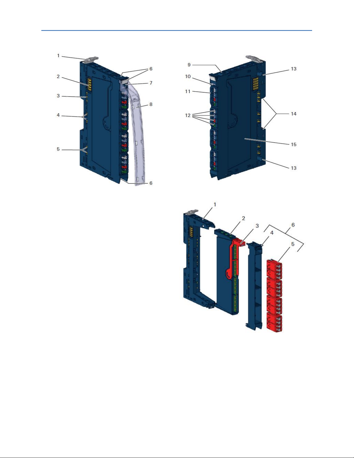
1.5 General Description of I/O Modules
I/O module (Example EP-1214)
1 Catch lever for securing the DIN rail
2 System bus
3 System current path
4 Input current path
5 Output current path
6 Seats for module markers
7 Type designation
8 Optional: swivel marker for labelling modules and
channels
9 Connector frame unlocking device
10 Module status LED (collective message)
11 Connector
12 Channel status LEDs
13 Latching hook for latching onto module sides
14 DIN rail foot
15 Type plate
I/O Module Components
Color Coding
The removal levers for the electronic unit and the
connectors are color-coded as follows:
• Blue standard
• White power supply
• Red 230 V
• Yellow SIL products
1 Basic module
2 Electronic unit
3 Removal lever for electronic unit
4 Connector frame
5 Connector
6 Plug-in unit
A detailed description of the individual module types is available in Chapter 5, Detailed Descriptions of I/O
Modules.

Chapter 1: Introduction
GFK-2958E RSTi-EP User Manual 14
1.5.1 Standard Connector
The connection frame can take up to four connectors, and four conductors can be connected to
each connector. Spring-style technology allows for fine-wired conductors with crimped wire-end
ferrules or ultrasonically welded conductors, each with a maximum cross-section of 1.5 mm², to be
inserted easily through the opening in the clamping terminal without having to use tools. To insert
fine-wired conductors without wire-end ferrules, the pusher must be pressed in with a screwdriver
(refer to the section, Wiring).
Connector with Four Conductor Connectors
Features and Specifications:
- conductor cross-section 0.14 to 1.5 mm²
(AWG 16 – 26)
- maximum ampacity: 10 A
- 4-pole
The pushers are color-coded for the following
connections:
• White Signal
• Blue GND
• Red 24 V DC
• Green Functional earth (FE)
1.5.2 HD Connector EP-8360
The connection frame can take up to four times two HD connectors EP-8360, and qualified SAI
cables† with a cross-section from 0.14 to 0.35 mm
2
can be connected to each connector via
insulation displacement contact (IDC). (wiring refer to section, Wiring)
Connector EP-8360 for HD Modules
Features and Specifications:
- conductor cross-section: 0.14 to 0.35 mm²
(AWG 22-26)
- insulation diameter 1.0 to 1.6 mm (0.04 to
0.06")
- maximum current capacity: 1 A
- 4-pole

Chapter 1: Introduction
GFK-2958E RSTi-EP User Manual 15
1.5.3 Cable Protection
The modules listed in the following table do not have a fused sensor/actuator power supply. Here, all
cables to the connected sensors/actuators must be fused corresponding to their conductor crosssections (as per Standard DIN EN 60204-1, section 12).
Description
Order No.
Digital input modules
Digital Input, 4 Points, Positive Logic 24VDC, 2,3, or 4 Wire
EP-1214
Digital Input, 8 Points, Positive Logic, 24VDC 2 Wire
EP-1218
Digital Input, 8 Points, Positive Logic, 24VDC 3 Wire
EP-1318
Digital Input, 4 Points, Positive Logic 24VDC, 2,3, or 4 Wire, Time stamp
EP-12F4
Digital Input, 4 Points 110/230 VAC (65 – 277 VAC), 2 Wire, Isolated
EP-1804
Digital output modules
Digital Output, 4 Points, Positive Logic 24VDC, 0.5A, 2,3, or 4 Wire
EP-2214
Digital Output, 4 Points, Positive Logic 24VDC, 2.0A, 2,3, or 4 Wire
EP-2614
Digital Output, 4 Points, Positive/Negative Logic 24VDC, 2.0A, 2,3, or 4 Wire
EP-2634
Analog input modules
Analog Input, 4 Channels Voltage/Current 16 Bits 2, 3, or 4 Wire
EP-3164
Analog Input, 4 Channels Voltage/Current 12 Bits 2, 3, or 4 Wire
EP-3124
Functional modules
2 Channels PWM Output, Positive Logic, 24VDC, 0.5 A
EP-5422
2 Channels PWM Output, Positive Logic, 24VDC, 2 A
EP-5442
1 Channel High Speed Counter, AB 100 kHz 1 DO 24VDC, 0.5A
EP-5111
2 Channel High Speed Counter, AB 100 kHz
EP-5112
2 Channel Frequency Measurement, 100 kHz
EP-5212
1 Channel Serial Communications, 232, 422, 485
EP-5261
1 Channel SSI Encoder, BCD or Gray-Code Format, 5/24 VDC
EP-5311
Potential distribution modules
Power Module, 16 Channels 24VDC Potential Distribution +24 VDC from Input Current Path
EP-711F
Power Module, 16 Channels 24VDC Potential Distribution +24 VDC from Output Current Path
EP-751F
Power Module, 16 Channels 24VDC Potential Distribution +0VDC from Input Current Path
EP-710F
Power Module, 16 Channels 24VDC Potential Distribution +0VDC from Output Current Path
EP-750F

Chapter 1: Introduction
GFK-2958E RSTi-EP User Manual 16
1.6 General Technical Data for I/O Modules
Type of connection
Spring-style
Single-wired, fine-wired
Conductor cross-section
0.14 – 1.5 mm2 (AWG 16 – 26)
IDC (EP-3368, EP-3468)
Single-wired, fine-wired
Conductor cross-section
0.14 – 0.35 mm2 (AWG 22 – 26)
Dimensions
Height
4.72 in (120.0 mm)
w/ release lever: 128.0 mm (5.04 in)
Width
11.5 mm (0.45in)
Depth
76.0 mm (2.99 in)
Protection class
(DIN EN 60529)
IP 20
Flammability rating UL 94
V-0
Temperature data
Operation
-20°C to +60°C (- 4 to +140 °F)
Storage, transport
-40°C to +85°C (- 40 to +185 °F)
Humidity
Operation, storage, transport
5 % to 95 %, non-condensing
as per IEC 61131-2
Air pressure
Operation
≥ 795 hPa (altitude ≤ 2000 m)
as per IEC 61131-2
Storage, transport
≥ 700 hPa (altitude ≤ 3000 m)
as per IEC 61131-2
Vibration resistance
5 Hz ≤ f ≤ 8.4 Hz: 3.5-mm amplitude as per IEC 60068-2-6
8.4 Hz ≤ f ≤ 150 Hz: 1-g acceleration as per IEC 60068-2-6
Shock resistance
15 g over 11 ms, half sinewave, as per IEC 60068-2-27
Potential isolation
Test voltage
max. 28.8 V within one channel
500 V DC field/system
Pollution severity level
2
Overvoltage category
II
Approvals and Standards
cULus Ordinary Locations
UL 508, CSA C22.2 No. 0-M91
CULUS
Hazardous Locations
Class 1 Division 2, Gr. A, B, C, D
ISA 12.12.01: 2007
CSA C22.2 No. 213-M1987 (Reaffirmed 2008)
Potentially explosive atmosphere
Zone 2†
ATEX Directive 2014/34/EU
Explosion protection
EN 60079-0:2012+A11:2013 and EN 6007915:2010
IEC 60079-0:2011 and
IEC 60079-15:2010
EMC
EN61000-6-2: 2005, EN61000-6-4: 2007 +
A1:2011, (partial standards as per the
requirements of EN61131‑2: 2007)
FCC Compliance
47 CFR 15: 2011 (Class A)
PLC
IEC 61131-2
Type of connection
Spring-style
Single-wired, fine wired
†
Unless otherwise noted within the product-specific technical data.
All product-specific technical data is available in the corresponding product description in Chapter 5, Detailed Descriptions
of I/O Modules.
Chapter 1: Introduction
GFK-2958E RSTi-EP User Manual 17
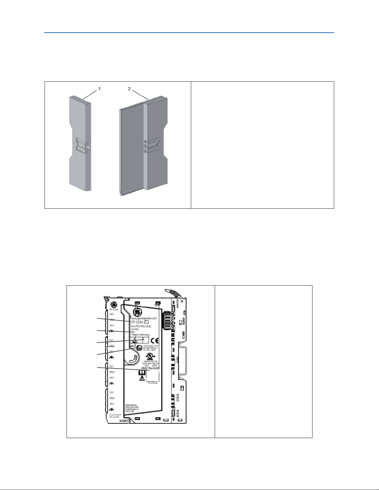
1.7 Mechanical Fixing Elements
The station is fixed in the installation position by an end bracket at either side. The last I/O module is
protected against dust by a cover plate, into which the second end bracket is inserted and screwed
to the mounting rail. Every RTSi-EP network adapter is supplied with a termination kit.
RSTi-EP station fixing elements
1 End bracket (left end, on the network adapter
side)
2 Termination kit with end plate and end
bracket (right end)
For vertical installation, a special end bracket
must also be installed below the station.
1.8 Type Plate
Each network adapter and each module features a type plate, which includes identification
information, the key technical specifications and a block diagram. In addition, a QR code allows for
direct online access to the associated documentation. The software for reading the QR code must
support inverted QR codes. A breakdown of the serial numbers can be found in the table provided in
the annex.
5
4
3
2
1
Type Plate (Example of EP-1214)
1 Product number
2 Serial number
3 Manufacturing code
4 ATEX marking
5 QR code
Chapter 1: Introduction
GFK-2958E RSTi-EP User Manual 18
1.9 Markers
A wide range of markers are available as accessories for labelling equipment.
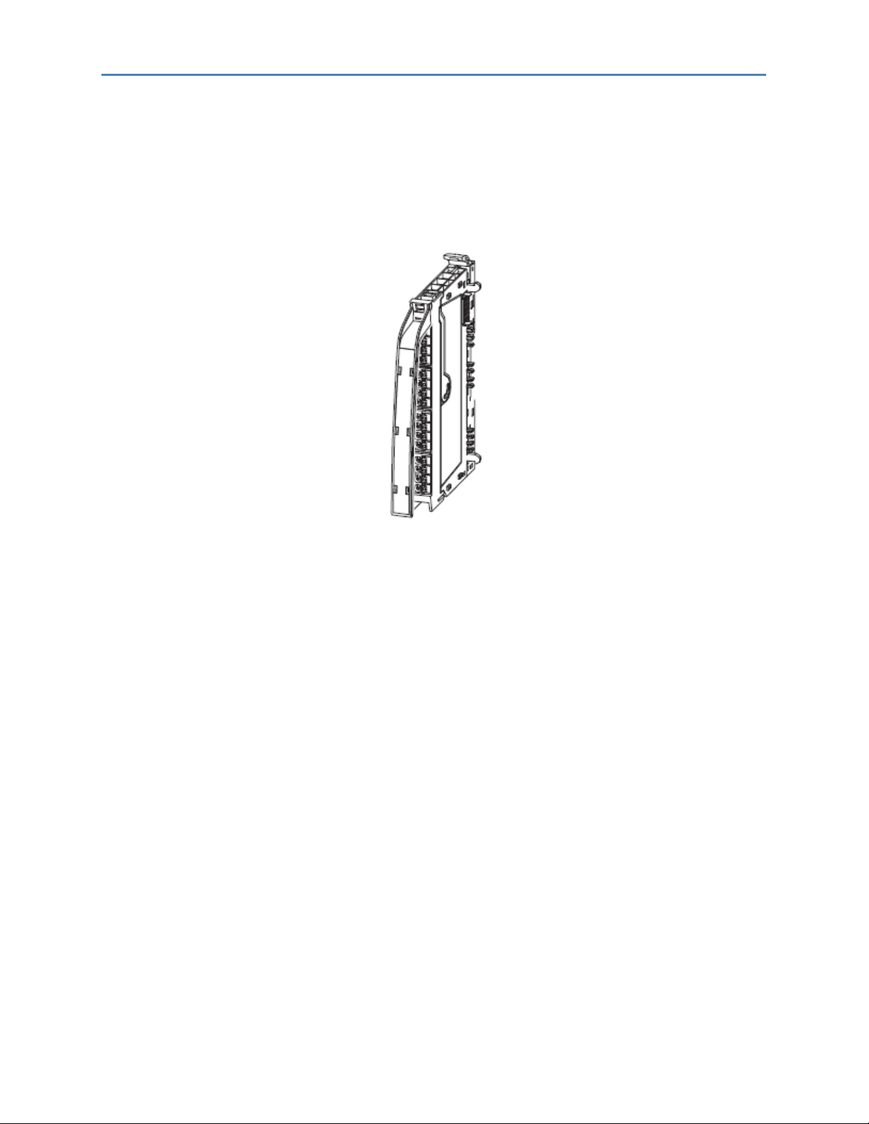
1.9.1 Swivel Marker
RSTi-EP I/O Label Markers (EP-8100) allow for modules and all respective channels and lines to be
labelled in detail. They are attached to the connector frame.
Module with Swivel Marker
The following labels are available for the labelling:
• Paper labels for printing with laser printers (Part No. EP-8101)
o White
o Yellow

Chapter 1: Introduction
GFK-2958E RSTi-EP User Manual 19
Notes

GFK-2958E RSTi-EP User Manual November 2017 20
Safety
This section includes general safety instructions for handling the RSTi-EP system. Specific safety
instructions for specific tasks and situations are given at the appropriate places in the
documentation.
When using remote I/O RSTi-EP modules, refer to the Module for Functional Safety Manual (GFK-2956).
2.1 General Safety Notice
Work on the RSTi-EP products may only be performed by qualified personnel with the support of
trained persons. As a result of their professional training and experience, an personnel is qualified to
perform the necessary work and identify any potential risks.
Before any work is carried out on the products (installation, maintenance, retrofitting), the power
supply must be switched off and secured against being switched on again. Work may be carried out
with safety extra-low voltage.
The manual provided with the equipment shall be followed in detail to assure proper and safe
operation.
A stabilized 24V DC power supply shall be used.
All field wiring intended for connection to the power terminal shall consist of copper conductors with
the insulation locally removed. Additional intermediate connecting parts, other than ferriles, shall not
be used.
When working during continued operations, the emergency stop mechanisms must not be made
ineffective. If you need technical help, contact Technical Support. For phone numbers and email
addresses, refer to the General Contact Information page in the front of this manual.
If a malfunction on a RSTi-EP product cannot be fixed after following the recommended measures
(refer to the Chapter, LED Indicators and Troubleshooting), the product in question must be sent back
to GE. GE does not assume any liability if the base or electronic module has been tampered with.
2.1.1 Electrostatic Discharge
RSTi-EP products can be damaged or destroyed by electrostatic discharge. When handling the
products, the necessary safety measures against electrostatic discharge (ESD) according to IEC
61340-5-1 and IEC 61340-5-2 must be observed.
All devices are supplied in ESD-protected packaging. The packing and unpacking as well as the
installation and disassembly of a device may only be carried out by qualified personnel and in
accordance with the ESD information.
2.1.2 Open Equipment
RSTi-EP products are open equipment (having live electrical parts that may be accessible to users)
that may only be installed and operated in lockable housings, cabinets or electrical operations
rooms. Only trained and authorized personnel may access the equipment.
For applications requiring functional safety or in order to maintain compliance with the ATEX
Directive [Class 1, Zone 2 area (Category 3)], the surrounding housing must meet at least IP 54.
The standards and guidelines applicable for the assembly of switch cabinets and the arrangement of
data and supply lines must be complied with.

Chapter2: Safety
GFK-2958E RSTi-EP User Manual 21
2.1.3 Fusing
The operator must set up the equipment so that it is protected against overloading. The upstream
fuse must be designed such that it does not exceed the maximum load current. The maximum
permissible load current of the RSTi-EP components can be found in the technical data.
In the case of modules without fused sensor/actuator power supplies, all lines to the connected
sensors/actuators must be fused corresponding to their conductor cross-section (as per DIN VDE
0298 Part 4).
To meet UL-specifications in accordance with UL 248-14, a UL-certified automatic fuse or a 10 A fuse
with a medium time-lag must be used.
All connections of the RSTi-EP components are protected against voltage pulses and overcurrent in
accordance with IEC 61131-2, Zone B. The operator has to decide whether additional overvoltage
protection according to IEC 62305 is required. Voltages that exceed +/-30 V may cause the
destruction of network adapters and modules.
A feed-in power supply with secure isolation must be used.
2.1.4 Earthing (functional earth FE)
Each RSTi-EP I/O module is fitted with an FE spring on the underside which creates an electrical
connection to the DIN rail. In order to establish a secure connection, the assembly must be carried
out carefully in accordance with the instructions (refer to Chapter 6, Installation). The module is
earthed by connecting the DIN rail to the protective earth via the earth terminal.
Modules EP-700F, EP-1214, EP-2214, EP-3124 and EP-3164 have connections with green pushers. An
FE potential is also provided at these connections. They must not be used as a PE.
2.1.5 Shielding
Shielded lines are to be connected with shielded plugs and fixed on a shield bus in compliance with
the relevant standard (refer to Chapter 7, Earthing and Shielding).
2.1.6 Overcurrent
Potentials of network adapters and power-feed modules must be disconnected either simultaneously
or in the order 24 V supply first, then the GND potential.
2.2 Intended Use
The products of the RSTi-EP series are intended for use in industrial automation. A RSTi-EP station
with network adapter and connected modules is intended for the decentralized control of systems or
sub-systems. Via the network adapter every module of a station is integrated into a fieldbus
structure and connected to the primary control unit. The RSTi-EP products conform to protection
class IP 20 (in accordance with DIN EN 60529), they can be used in potentially explosive atmospheres
rated as Zone 2 (as per Directive 2014/34/EU) and in safe zones.
The observance of the supplied documentation is part of the intended use. The products described in
this manual may only be used for the intended applications and only in connection with certified
third-party devices or components.

Chapter2: Safety
GFK-2958E RSTi-EP User Manual 22
2.3 Use in a Potentially Explosive Atmosphere
If RSTi-EP products are used in potentially explosive atmospheres, the following notes are also
applicable:
• Staff involved in assembly, installation and operation must be qualified to perform safe
work on electrical systems protected against potentially explosive atmospheres.
• The remote I/O-System RSTi-EP shall only be used in an area of not more than pollution
degree 2, as defined in IEC 60664-1.
• For applications in potentially explosive atmospheres, the requirements according to IEC
60079-15 must be observed, in particular the housing enclosing the system must meet
the requirements of explosion protection type Ex n or Ex e and protection class IP54. The
IP54 enclosure must be accessible only by the use of a tool.
• Sensors and actuators that are located in Zone 2 or in a safe zone can be connected to
the RSTi-EP station.
• The ambient temperature range -20°C to +60°C shall not be exceeded.
• When the temperature under rated conditions exceeds 70 °C at the conductor or conduit
entry point, or 80 °C at the contact, the temperature specification of the selected cable
shall be in compliance with the actual measured temperature values.
• A stabilized 24V DC power supply with double or reinforced insulation shall be used.
• When using modules EP-2714, EP-2814, and EP-1804 in explosive atmosphere:
o Device shall be installed in an environment free of condensation, corrosives and
conducting dusts.
o If the switching or input voltage exceeds 63V, a transient protection device shall be
provided that limits the transients to a peak voltage of 500V or less.
• For EP-2714 (Relay Module) only:
o Since relays are subject to wear, it must be ensured, by appropriate maintenance
intervals, that the temperatures do not exceed the limits of temperature class T4.
Note: A contact resistance of more than 110 milli-ohm will be considered as a fault.
o Resistive Loads Only
• For EP-2714 and EP-2814 Relay Modules:
o Transient protection shall be provided that is set at a level not exceeding 140% of the
peak rated voltage value at the supply terminals to the equipment.
• A visual inspection of the RSTi-EP station is to be performed once per year.
• If mounted in other directions than horizontal (reference mounting rail), restrictions to the
max. operating temperature, max. output currents may apply.
• While explosive atmosphere is present:
o No electrical connection shall be separated in energized condition.
o The USB interface shall not be used.
o Dip-switches, binary-switches and potentiometers shall not be actuated.
• Only power supplies with secure isolation shall be used.
• Refer manufacturers manual.

Chapter2: Safety
GFK-2958E RSTi-EP User Manual 23
Warning
EXPLOSION HAZARD - SUBSTITUTION OF COMPONENTS MAY IMPAIR
SUITABILITY FOR CLASS I, DIVISION 2.
WHEN IN HAZARDOUS LOCATIONS, TURN OFF POWER BEFORE REPLACING
OR WIRING MODULES; AND
DO NOT CONNECT OR DISCONNECT EQUIPMENT UNLESS POWER HAS
BEEN SWITCHED OFF OR THE AREA IS KNOWN TO BE NONHAZARDOUS.
2.3.1 ATEX Zone 2
The modules must be mounted in an enclosure certified in accordance with EN60079-15 for use in
Zone 2, Group IIC and rated IP54. The enclosure shall only be able to be opened with the use of a tool.
2.3.2 ATEX & IECEx Marking
II 3 G Ex nA IIC T4 Gc, DEMKO 16 ATEX 1591X
Ex nA IIC T4 Gc, IECEx ULD 16.0022X
Ta: -20 °C to +60 °C
For Relay Modules:
II 3 G Ex nA nC IIC T4 Gc, DEMKO 16 ATEX 1591X
Ex nA nC IIC T4 Gc, IECEx ULD 16.0022X
Ta: -20 °C to +60 °C
2.4 Legal Notice
The RSTi-EP series products are CE-compliant in accordance with Directive 2014/30/EU (EMC
Directive) and Directive 2014/35/EU (Low Voltage Directive). They also meet the requirements of the
ATEX Directive 2014/34/EU.
2.5 Use of RSTi-EP Stations Above 2000m Sea Level
The RSTi-EP remote I/O system is able to operate in height >2000 m (6561.68 ft) above sea
level, with the following limitations:
There is a derating for ambient temperatures while the RSTi-EP Station is in operating
mode. Refer to the following derating table.
Altitude (m, ft)
Factor for Temperature Derating
< 2000 m (6561.68 ft)
1
2001 to 3000 m (6564.96 to 9842.52 ft)
0.88
3001 to 4000 m (9845.80 to 13123.36 ft)
0.78
4001 to 5000 m (13126.64 to 16404.20 ft)
0.68
Example:
Height 3000 m (9842.52 ft): maximum operational temperature is 60° C (140 °F) x 0.88 = 52.8°C
(136.76 °F) at maximum 8A.

GFK-2958E RSTi-EP User Manual November 2017 24
Configuration
3.1 Order and Arrangement of the Modules
The RSTi-EP system elements are designed to be installed on a profile rail according to EN 60715 [1.4
x 0,26 in (35 × 7.5 mm)], a steel strip in accordance with Annex A of EN 60715, or a tin-plated steel
strip.
Note: A RSTi-EP station may be built up to a maximum length of 3.28 ft (1 m). Therefore, at most
82 modules (including max. 64 active modules) can be aligned on a network adapter.
The RSTi-EP station is usually installed on a horizontally positioned DIN rail.
Installation Position of the RSTi-EP Station on the DIN Rail (Horizontal Installation)
Installation on vertically positioned DIN rails is also possible. In this case however, the heat
dissipation is reduced such that the derating values change (refer to the section Current Demand and
Power Supply). In the case of vertical mounting, the network adapter must always be arranged as the
first module at the bottom and secured with an end bracket for vertical mounting.

Chapter 3: Configuration
GFK-2958E RSTi-EP User Manual 25
Installation Position of the RSTI-EP Station on the DIN Rail (Vertical Installation)
A RSTi-EP station may only be installed in this sequence (starting from the left/bottom):
• End bracket
• Network adapter
• Up to 82 modules (including max. 64 active modules)
• End plate and end bracket
Attention
A maximum of three passive modules (potential distribution module, powerfeed module or blank module) may be placed in successive positions. Then at
least one active module must follow.
3.1.1 Arrangement of Safe Power-feed Modules
A safe power-feed module EP-19xx module can be positioned anywhere in the RSTi-EP station. All the
following output modules (except for the EP-2814 and EP-2714 relay modules) up to the next EP-19xx
module are safely disconnected (safety segment). Multiple EP-19xx modules/safety segments can be
arranged within a station.
Note: When using RSTi-EP EP-19xx modules, also refer to the Modules for Functional Safety Manual
(GFK-2956).
Chapter 3: Configuration
GFK-2958E RSTi-EP User Manual 26
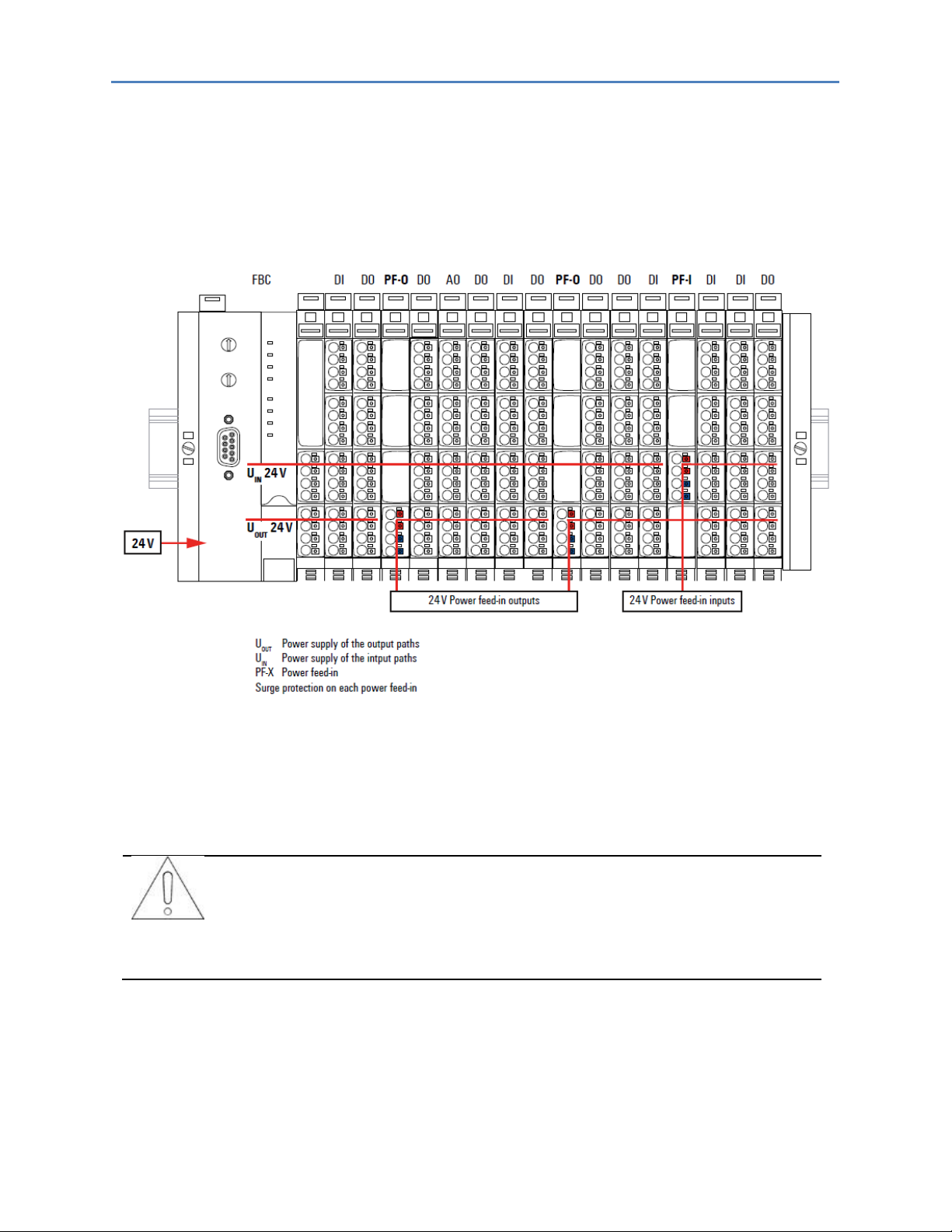
3.1.2 Power Supply Concept
The RSTi-EP system uses three internal current paths as described in the following chapter, Detailed
Descriptions of the Fieldbus Network Adapters. Input and output paths are supplied separately, therefore a
custom-fit refreshing by power-feed modules is easily feasible.
The following figure shows the general supply concept. For detailed description and calculation of the current
demand refer to the sections, Example Calculation for the Power Supply and Calculation of Power Loss of
this manual.
3.2 Installation Distances
In order to be able to carry out the installation and subsequent maintenance work and to ensure
sufficient ventilation, the RSTi-EP station must be installed while observing the following minimum
distances (refer to the following figures).
Attention
Depending on how the station shielding is implemented, the specified
distances may have to be made larger, where necessary.
The minimum permissible conductor bending radii must also be observed. Earth terminals already
installed can be ignored when calculating the distance.
 Loading...