

GE GFK-2892F User Manual

GE
Automation & Controls
For Public Disclosure
Programmable Control Products
PACSystems RX3i Genius Communications Gateway User Manual GFK-2892F
PACSystems RX3i Genius
Communications
Gateway
User Manual
GFK-2892F
March 2019
Legal Information
Warnings, Cautions, and Notes as Used in this Publication GFL-002
Warning
Warning notices are used in this publication to emphasize that hazardous voltages,
currents, temperatures, or other conditions that could cause personal injury exist in
this equipment or may be associated with its use.
In situations where inattention could cause either personal injury or damage to
equipment, a Warning notice is used.
Caution
Caution notices are used where equipment might be damaged if care is not taken.
Note: Notes merely call attention to information that is especially significant to understanding
and operating the equipment.
These instructions do not purport to cover all details or variations in equipment, nor to provide for every
possible contingency to be met during installation, operation, and maintenance. The information is supplied for
informational purposes only, and GE makes no warranty as to the accuracy of the information included herein.
Changes, modifications, and/or improvements to equipment and specifications are made periodically and
these changes may or may not be reflected herein. It is understood that GE may make changes, modifications,
or improvements to the equipment referenced herein or to the document itself at any time. This document is
intended for trained personnel familiar with the GE products referenced herein.
GE may have patents or pending patent applications covering subject matter in this document. The furnishing
of this document does not provide any license whatsoever to any of these patents.
GE PROVIDES THE FOLLOWING DOCUMENT AND THE INFORMATION INCLUDED THEREIN AS-IS AND
WITHOUT WARRANTY OF ANY KIND, EXPRESSED OR IMPLIED, INCLUDING BUT NOT LIMITED TO ANY IMPLIED
STATUTORY WARRANTY OF MERCHANTABILITY OR FITNESS FOR PARTICULAR PURPOSE.
* indicates a trademark of General Electric Company and/or its subsidiaries.
All other trademarks are the property of their respective owners.
©Copyright 2014-2019 General Electric Company.
All Rights Reserved

Contact Information
If you purchased this product through an Authorized Channel Partner, please contact the seller directly.
General Contact Information
Online technical support and GlobalCare
www.geautomation.com/support
Additional information
www.geautomation.com
Solution Provider
solutionprovider.ip@ge.com
Technical Support
If you have technical problems that cannot be resolved with the information in this manual, please contact us
by telephone or email, or on the web at www.geautomation.com/support
Americas
Phone
1-800-433-2682
International Americas Direct Dial
1-780-420-2010 (if toll free 800 option is unavailable)
Customer Care Email
digitalsupport@ge.com
Primary language of support
English
Europe, the Middle East, and Africa
Phone
+800-1-433-2682
EMEA Direct Dial
+ 420-296-183-331 (if toll free 800 option is unavailable or
if dialing from a mobile telephone)
Customer Care Email
digitalsupport.emea@ge.com
Primary languages of support
English, French, German, Italian, Spanish
Asia Pacific
Phone
+86-21-3877-7006 (India, Indonesia, and Pakistan)
+86-400-820-8208 (rest of Asia)
Customer Care Email
digitalsupport.apac@ge.com
Primary languages of support
Chinese, English


GFK-2892F March 2019 i
Table of Contents
PACSystems RX3i Genius Communications Gateway User Manual GFK-2892F
Table of Contents ............................................................................................................................................................. i
Table of Figures ............................................................................................................................................................... iv
Chapter 1 Introduction ............................................................................................................................................... 1
1.1 Revisions in this Manual .......................................................................................................................... 2
1.2 Acronyms and Abbreviations ................................................................................................................ 3
1.3 PACSystems Documentation................................................................................................................. 4
1.4 Description ................................................................................................................................................. 5
1.5 Product Overview ..................................................................................................................................... 6
1.6 Specifications ............................................................................................................................................ 7
1.7 Controls and Indicators ........................................................................................................................... 8
Mounting ................................................................................................................................................................ 9
1.8 PROFINET Operation Overview........................................................................................................... 10
1.9 System Limits .......................................................................................................................................... 14
1.10 Operational Differences vs. Genius Bus Controller ........................................................................ 15
1.11 Supported Genius Devices.................................................................................................................... 16
Chapter 2 Installation ............................................................................................................................................... 17
2.1 Pre-Installation Check ........................................................................................................................... 17
2.2 Installation Location .............................................................................................................................. 17
2.3 Installation in Hazardous Areas .......................................................................................................... 18
ATEX Zone 2 ....................................................................................................................................................... 18
ATEX Marking ..................................................................................................................................................... 18
2.4 Module Installation ................................................................................................................................ 19
Install SD Card ................................................................................................................................................... 19
Mounting the GCG001 ................................................................................................................................... 19
GCG001 Module Removal ............................................................................................................................. 21
Light-Emitting Diode (LED) Indications ................................................................................................... 22
Fault Notifications ........................................................................................................................................... 23

Contents
ii PACSystems RX3i Genius Communications Gateway GFK-2892F
2.5 Configuring the Genius Gateway to Operate with the RX3i CPU ............................................... 24
2.6 Ethernet Port Connections .................................................................................................................. 25
RJ-45 Port Connections ................................................................................................................................. 25
2.7 Firmware Updates .................................................................................................................................. 26
2.8 Spare Parts ............................................................................................................................................... 26
Chapter 3 Configuration ........................................................................................................................................... 27
3.1 Configuration Tools ................................................................................................................................ 27
3.2 Configuration Overview ........................................................................................................................ 27
GCG001 in Simplex Genius Bus Configuration ..................................................................................... 27
Genius Hot-Standby Redundancy Configuration ................................................................................ 33
Genius Duplex Configuration ...................................................................................................................... 34
Genius Dual Bus Configuration ................................................................................................................... 34
Genius Hot Standby Dual Bus Configuration ........................................................................................ 35
Chapter 4 System Operation ................................................................................................................................... 37
4.1 System Overview .................................................................................................................................... 37
Communications .............................................................................................................................................. 37
Redundancy ........................................................................................................................................................ 38
I/O Scans .............................................................................................................................................................. 39
Alarms................................................................................................................................................................... 40
Chapter 5 Diagnostics ............................................................................................................................................... 41
5.1 Status Data ............................................................................................................................................... 42
Gateway Status Data ...................................................................................................................................... 42
Genius Status Data.......................................................................................................................................... 43
Fault Status Data ............................................................................................................................................. 43
5.2 Module LED Indicators .......................................................................................................................... 43
5.3 Power-Up .................................................................................................................................................. 44
Problems during Power-up .......................................................................................................................... 44
Transitioning from Firmware Update Mode to Operational Mode .............................................. 44
5.4 Module Faults in the RX3i I/O Fault Tables ....................................................................................... 45
Fault Types Reported to the RX3i Controller I/O Fault Table ......................................................... 46
Clearing the RX3i Fault Tables .................................................................................................................... 47
Chapter 6 COMMREQ/Data_Init_Comm Programming ..................................................................................... 49
6.1 COMMREQs and Passwords ................................................................................................................. 50
6.2 Programming for a COMMREQ Communication Request ............................................................. 50
6.3 COMMREQ Command Block Format .................................................................................................. 51
COMMREQ Command Block Contents .................................................................................................... 52
Contents
GFK-2892F March 2019 iii
COMMREQ Commands Supported by the Genius Gateway (GCG001) ..................................... 53
COMMREQ Command Block Quick Reference ..................................................................................... 54
Mechanics of the COMMREQ Instruction ............................................................................................... 55
Comparison: COMMREQ vs Data_Init_Comm ...................................................................................... 60
COMMREQ Differences: Genius Bus Controllers and Genius Gateway ..................................... 61
6.4 COMMREQ Descriptions and Formats ............................................................................................... 62
COMMREQ #1: Pulse Test Command....................................................................................................... 62
COMMREQ #2: Read Configuration Command .................................................................................... 63
COMMREQ #3: Write Configuration Command ................................................................................... 64
COMMREQ #4: Read Diagnostics Command ........................................................................................ 65
COMMREQ #5: Clear Circuit Fault Command ....................................................................................... 66
COMMREQ #6: Clear All Circuit Faults Command .............................................................................. 67
COMMREQ #7: Assign Monitor Command ............................................................................................. 68
COMMREQ #8: Enable/Disable Outputs Command ........................................................................... 69
COMMREQ #10: Switch BSM Command ................................................................................................. 70
COMMREQ #11: Read Device Command ................................................................................................ 71
COMMREQ #12: Write Device Command .............................................................................................. 72
COMMREQ #19: Read Identification ......................................................................................................... 73
COMMREQ #20: Write Point Command ................................................................................................. 75
COMMREQ #21: Read Block I/O Command ........................................................................................... 76
COMMREQ #22: Read Map Command ..................................................................................................... 80
COMMREQ #23: Write Map Command ................................................................................................... 81
COMMREQ #24: Read Data Command .................................................................................................... 82
COMMREQ #25: Write Data Command .................................................................................................. 83

Contents
iv PACSystems RX3i Genius Communications Gateway GFK-2892F
Table of Figures
Figure 1: Simplex PLC System Using Genius Gateway GCG001 .................................................................................................. 5
Figure 2: GCG001 Module ............................................................................................................................................................................ 6
Figure 3: Genius Gateway GCG001 Front Panel View ...................................................................................................................... 8
Figure 4: GCG001 Panel Mount Diagram .............................................................................................................................................. 9
Figure 5: Application Relationships between PROFINET Controller & Genius Gateway .................................................... 10
Figure 6: Real-Time & Non-Real-Time Data Types ........................................................................................................................... 11
Figure 7: PLC - GCG - Genius Scan Cycles ........................................................................................................................................... 12
Figure 8: Rear View of GCG001 ............................................................................................................................................................... 19
Figure 9: GCG001 Power Connector ...................................................................................................................................................... 19
Figure 10: Daisy Chain Genius Bus Wiring ......................................................................................................................................... 20
Figure 11: Genius Bus Wiring for Bus Termination .......................................................................................................................... 20
Figure 12: PROFINET Discovery Screenshot ....................................................................................................................................... 21
Figure 13: GCG001 Firmware Upgrade ZIP File UnZIPped to SD Card ..................................................................................... 26
Figure 14: Hardware Configuration Expanded Tree ........................................................................................................................ 28
Figure 15 - GCG Data Reference Addresses ........................................................................................................................................ 28
Figure 16: Genius Gateway Parameters .............................................................................................................................................. 28
Figure 17: Change Module List for Genius Gateway GCG001 ..................................................................................................... 29
Figure 18: Populating the Genius IO Devices to be Controlled by the Genius Gateway .................................................... 30
Figure 19: Populating Slots in S90-70 Rack Controlled by Remote I/O Scanner (BEM733) ............................................. 30
Figure 20: PME Display of Complete Genius Gateway Configuration ...................................................................................... 32
Figure 21: GCG001 Units Deployed in Genius Hot Standby Dual Bus Redundancy ........................................................... 36
Figure 22: Genius Hot Standby Redundancy ..................................................................................................................................... 38
Figure 23: PROFINET Media Redundancy ............................................................................................................................................ 39
Figure 24: Gateway Status Data ............................................................................................................................................................. 42
Figure 25: Genius Status Data ................................................................................................................................................................. 43
Figure 26: Fault Status Data ..................................................................................................................................................................... 43
Figure 27 - I/O Fault Table Message Identifiers ................................................................................................................................. 46
Figure 28: Genius Discrete Block Failed Switch Fault Display (Example) ............................................................................... 47
Figure 29: Genius Analog Block Over Range Fault Display (Example) ..................................................................................... 47
Figure 30: Ladder Logic to Clear Circuit Fault .................................................................................................................................... 59
Figure 31: Data_Init_Comm to Clear Circuit Fault ............................................................................................................................ 60

GFK-2892F March 2019 1
Chapter 1 Introduction
This manual describes the RX3i Genius Communications Gateway, which acts as a gateway between
PROFINET and Genius I/O. Introductory material may be found in this chapter. Chapter 2 provides installation
and set-up information. Chapter 3 provides configuration instructions. Chapter 4 describes system operation.
Chapter 5 provides diagnostic information. Chapter 6 covers the use and format of ladder logic COMMREQ
instructions.

Chapter 1. Introduction
2 PACSystems RX3i Genius Communications Gateway GFK-2892F
1.1 Revisions in this Manual
Rev
Date
Description
F
Mar
2019
• In Section 5.1.3, added Fault Status Data.
E
Oct
2018
• Added note 3.2.2 concerning PNC001 Critical Network Ports feature with GCGs.
D
Mar
2018
• Added compatibility with CPE302.
C
Dec
2017
• Added support for Field Control Bus Interface Unit.
• Added Outputs at Startup hardware configuration parameter.
• Added Enable/Disable Outputs and Switch BSM COMMREQs.
• Documented GCG001 Units deployed in Genius Hot Standby Dual Bus Redundancy
(Section 3.2.5).
B
Aug
2016
• Added support for VersaMax Genius Network Interface (GNIU)
• Added support for IC660BSS101 isolated I/O block
• Added support for additional Genius baud rates
A
Mar
2015
• Behavior of GCG001 with respect to input references associated with a faulted block
is described in Section 1.10, with workaround in Section 4.1.4.
• Correction to Figure 22: Genius Hot Standby Redundancy to indicate CPU type is CRU
and RMX modules are required.
• Clear All Faults can now be dispatched to all blocks on the bus in a single command.
See Section 6.4.6.
-
Jun
2014
Initial release

Chapter 1. Introduction
GFK-2892F March 2019 3
1.2 Acronyms and Abbreviations
AR
PROFINET Application Relationship
CR
PROFINET Communication Relationship
DCP
PROFINET Discovery & Configuration Protocol
GBIU
Genius Bus Interface Unit
GCG
Genius Communications Gateway (specifically GCG001)
GENA
Genius Network Adaptor
GENI
Genius Network Interface
GNIU
Genius Network Interface Unit
GR7
Series 90-70 Remote I/O Scanner (IC697BEM733)
GSDML
General Station Description Markup Language
HHM
Genius Hand-Held Monitor
HWC
Hardware Configuration (in PME)
LAN
Local Area Network
LED
Light Emitting Diode
MRC
Ethernet Media Redundancy Client
MRM
Ethernet Media Redundancy Manager
MRP
Ethernet Media Redundancy Protocol
NRT
Non-Real-Time PROFINET Communication
PCIM
Personal Computer Interface Module
PME
Proficy® Machine Edition
PNC
PROFINET Controller
PPV
PLC Protocol Variables
RT
Real-Time PROFINET Communication
SBA
Genius Serial Bus Address
SD
Secure Digital Card Slot
STP
Shielded Twisted Pair
UTP
Unshielded Twisted Pair

Chapter 1. Introduction
4 PACSystems RX3i Genius Communications Gateway GFK-2892F
1.3 PACSystems Documentation
PACSystems Manuals
PACSystems RX7i, RX3i and RSTi-EP CPU Reference Manual
GFK-2222
PACSystems RX7i, RX3i and RSTi-EP CPU Programmer’s Reference Manual
GFK-2950
PACSystems RX7i, RX3i and RSTi-EP TCP/IP Ethernet Communications User Manual
GFK-2224
PACSystems TCP/IP Ethernet Communications Station Manager User Manual
GFK-2225
C Programmer’s Toolkit for PACSystems
GFK-2259
PACSystems Memory Xchange Modules User’s Manual
GFK-2300
PACSystems Hot Standby CPU Redundancy User Manual
GFK-2308
PACSystems Battery and Energy Pack Manual
GFK-2741
Proficy Machine Edition Logic Developer Getting Started
GFK-1918
Proficy Process Systems Getting Started Guide
GFK-2487
PACSystems RXi, RX3i, RX7i and RSTi-EP Controller Secure Deployment Guide
GFK-2830
PACSystems RX3i & RSTi-EP PROFINET I/O Controller Manual
GFK-2571
PACSystems RX3i Genius Communications Gateway
GFK-2928
RX3i Manuals
PACSystems RX3i System Manual
GFK-2314
PACSystems RX3i PROFINET Scanner Manual
GFK-2737
PACSystems RX3i CEP PROFINET Scanner User Manual
GFK-2883
Distributed I/O Systems Manuals
Genius I/O System and Communications User’s Manual
GEK-90486-1
Genius I/O Analog and Discrete Blocks User’s Manual
GEK-90486-2
Genius Hand-Held Monitor User’s Guide
GFK-0121
Series 90-70 Remote I/O Scanner User’s Manual
GFK–0579
VersaMax Systems Manuals
VersaMax System Genius Network Interface Unit User’s Manual
GFK-1535
In addition to these manuals, datasheets and product update documents describe individual modules and
product revisions. The most recent PACSystems documentation is available on the GE Automation & Controls
support website www.geautomation.com/support.
Chapter 1. Introduction
GFK-2892F March 2019 5
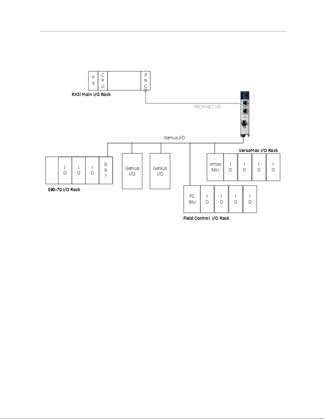
1.4 Description
The RX3i Genius Communications Gateway, IC695GCG001 (or GCG001), interfaces Genius IO devices on a
Simplex Genius Serial Bus to a GE PROFINET IO Controller.
Figure 1: Simplex PLC System Using Genius Gateway GCG001
The GCG001 operates as a Genius Bus Controller on a Genius network. It scans the Genius IO devices
configured to it, retrieving input data and providing output data. It then exchanges that data with its configured
PROFINET IO Controller over its Ethernet interfaces at the configured production rate. The GCG001 can
manage communications for up to 31 Genius IO devices on a single Genius Serial Bus.
The GCG001 also operates as an IO Device on PROFINET. It may be controlled by any of the following PROFINET
IO Controllers:
• PNC001 (the RX3i rack-mounted PNC module), or by
• CPE330 LAN 2 when configured as a PROFINET LAN, or by
• CPE400 LAN 2 when configured as a PROFINET LAN.
Thus, when correctly configured, the entire Genius Bus, including the GCG001 itself, becomes visible to the
controlling PLC. Note that the GCG001 operates only with GE PLC PROFINET IO Controllers.
PROFINET operates on an Ethernet network. If the Ethernet network or Genius serial bus communications are
lost, the GCG001 manages I/O states according to the individual module configurations.
Both PROFINET and Genius may be set up in Redundant configurations. These are discussed later in this
manual.

Chapter 1. Introduction
6 PACSystems RX3i Genius Communications Gateway GFK-2892F
1.5 Product Overview
Features of the GCG001 module include:
• Attachment of two RJ-45 Ethernet connections (Ports 1 & 2)
• Support for both star (switched) and linear (daisy-chained) network
topologies
• Supports Ethernet Media Redundancy Protocol (MRP)
• LEDs to indicate Ethernet status (ACT & LINK)
• Genius bus terminal block attachment
• Supports Genius Redundancy consisting of a single Genius bus with two
GCG001 Gateways, one at SBA #30 and the other at SBA #31.
• LED to indicate Genius Communications Status (COM)
• LEDs to indicate module status (refer to module header)
• Panel-mount (typical)
• Optional mounting in RX3i expansion slot
• Cable tie-down loop on underside of module (at front)
• 24Vdc power connector on underside of module
• 0.2A maximum current draw
• Secure Digital (SD) Card Slot, accessible at rear of module
• Firmware load pushbutton, accessible at rear of module
ETHERNET
ACT
LINK
PORT 1
PORT 2
COM
POWER
FAULT
CONNECT
OK
GCG001
LINK
ACT
GENIUS A
SER 1
SER 2
SHLD
IN
GENIUS
SHLD
OUT
Figure 2: GCG001
Module
Note: Although the hardware supports the 10/100BASE TX Ethernet standard, PROFINET I/O
over wired infrastructure must be 100Mbps full-duplex or faster. 10Mbps should not be
used for PROFINET.

Chapter 1. Introduction
GFK-2892F March 2019 7
1.6 Specifications
RX3i Genius Communications Gateway Specifications
PROFINET Support
PROFINET version 2.3 Class A IO-Device
CPU Compatibility
RX3i CPE330
RX3i CPE302/CPE305/CPE310 with firmware version 8.15 or later
RX3i CPU315/CPU320/CRU320 with firmware version 8.15 or later
Rx3i CPE302 (any firmware version)
PNC001 Compatibility
Firmware version 2.05 or later
Embedded PROFINET
Compatibility
RX3i CPE400 embedded PROFINET
RX3i CPE330 embedded PROFINET with firmware version 8.90 or
later
Proficy* Machine Edition
Compatibility
PME 8.0 or later
Power Requirements
External 24Vdc: (±10%) 0.2A
Operating Temperature Range
0 to 60°C
Number of Port Connectors
Two RJ-45
Local Area Network (LAN)
IEEE 802.2 Logical Link Control Class I
IEEE 802.3 CSMA/CD Medium Access Control 10/100 Mbps
Status Data
64 (two banks of 32 bits)
Genius Bus Support
Supports One Genius Bus.
Serial 1, Serial 2, Shield In and Shield Out, as marked.
Up to 29 additional devices supported per Genius Bus.
Selectable Baud Rate, per Genius specifications.
Genius Hot Standby and Duplex Redundancy supported.
HHM Compatibility
IC660HHM501
Other Genius Compatibility
See table in Section 1.11
SD Card
2GB or smaller. Not compatible with SDHC or SDXC cards.
Configuration
GSDML file is available on the Support website for download and
import into PME. The GSDML supporting a firmware release is part
of the firmware upgrade kit available on the Support website.
Hot Swappable
The Genius Gateway requires an external 24Vdc power supply
and does not draw power from the Rx3i backplane. Swapping out
the GCG001 will therefore not impact the PLC. However, this
cannot be performed without disconnecting its power supply. If
configured to support Genius Hot Standby, the loss of a single
GCG001 will be tolerated; otherwise not.
For system standards, general operating specifications, and installation requirements, refer to the PACSystems
RX3i System Manual, GFK-2314.
Chapter 1. Introduction
8 PACSystems RX3i Genius Communications Gateway GFK-2892F
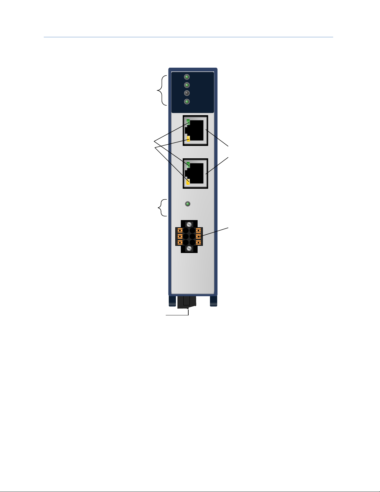
1.7 Controls and Indicators
The following figure shows the front of the module and identifies the controls and indicators.
ETHERNET
ACT
LINK
PORT 1
PORT 2
COM
POWER
FAULT
CONNECT
OK
GCG001
LINK
ACT
GENIUS A
SER 1
SER 2
SHLD
IN
GENIUS
SHLD
OUT
Module Status
Indicator LEDs:
POWER, OK,
FAULT,
CONNECT
Ethernet Port
Indicator LEDs:
LINK,
ACT
24 V dc
Power
Connector
Genius Bus
Indicator LEDs:
COM
PROFINET
Ports
Genius Bus
Connector
Figure 3: Genius Gateway GCG001 Front Panel View
Chapter 1. Introduction
GFK-2892F March 2019 9
Mounting
The GCG001 may either be panel-mounted or be mounted in the rightmost slot (expansion slot) of an RX3i
rack (IC695CHS012 or IC695CHS016).
Note: The SD Card supplied with the GCG001 will have been installed at the factory. See
section 2.4.1 for instructions for installing the SD Card when doing a retrofit. The
presence of the SD Card should be checked before mounting the module.
Note: Clearance of 3 inches (75mm) must be provided above and below the module for proper
ventilation and to permit cable access.
Note: External power must always be supplied to the module, regardless of which mounting
arrangement is chosen. When rack-mounted, the GCG001 does not draw power from the
RX3i Universal Backplane.
RX3i Backplane Mounting
The GCG001 may be mounted in the rightmost slot
(expansion slot) of an RX3i Universal Backplane.
The two captive M3.5 screws at the rear of the GCG001
align with mating tapped holes on the right side of the
backplane, providing a convenient mounting location.
When rack-mounted, the module does not make contact
with the backplane connector.
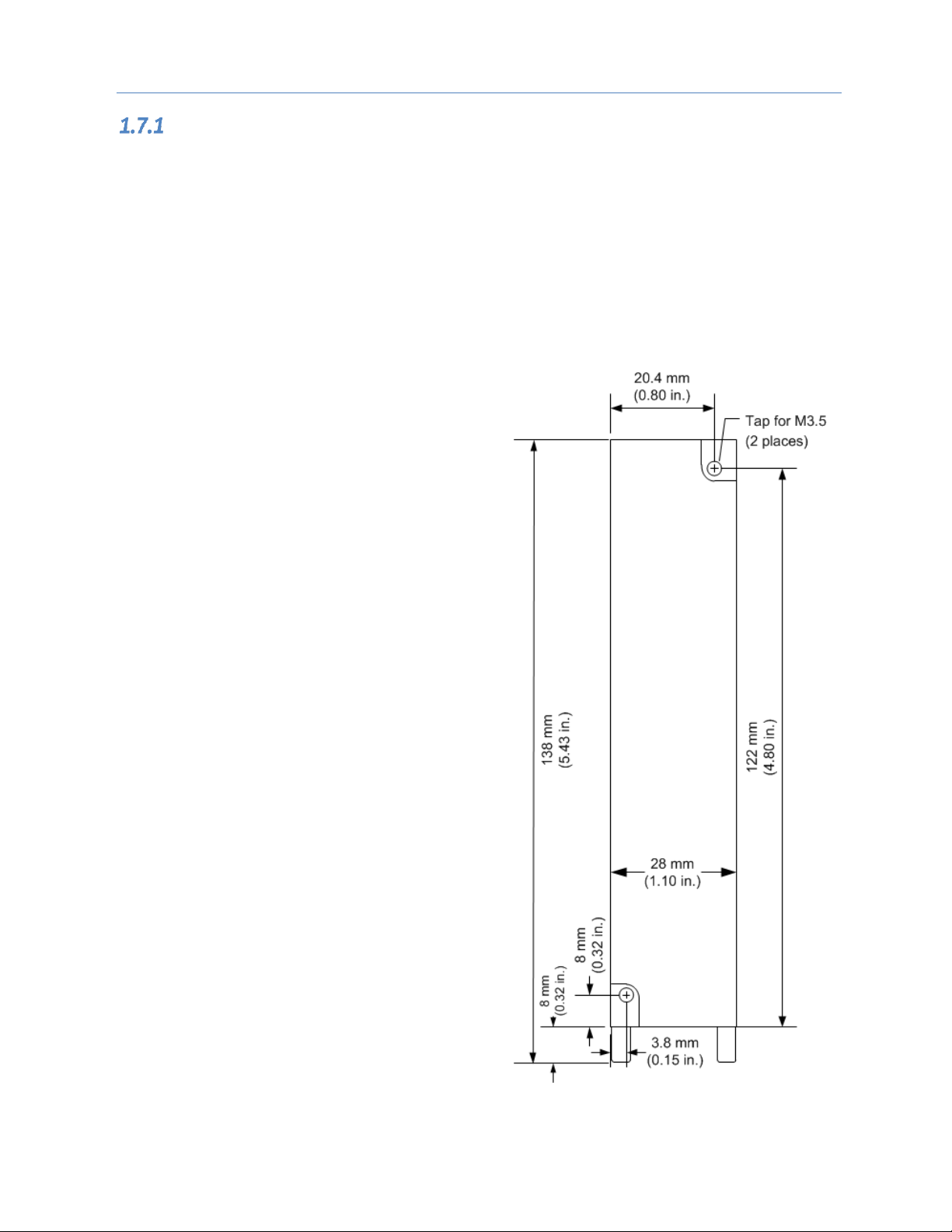
Panel-Mounting
Panel-mounting allows for mounting where no RX3i
backplane slot is available. The two captive M3.5 machine
screws on the GCG001 can be used for attaching the unit
to a panel.
Note: The panel must have a minimum
thickness of 2.4mm (0.094in).
1. Drill two mounting holes using the spacing
shown in the drawing (at right) and tap for
M3.5 (3.5 x 0.6mm).
2. Align the two mounting screws of the module
with the mounting holes in the panel.
3. Using a Philips screwdriver, tighten the two
screws to a maximum torque of 0.5 Nm
(4.4 in-lbs).
Figure 4: GCG001 Panel Mount Diagram
Chapter 1. Introduction
10 PACSystems RX3i Genius Communications Gateway GFK-2892F
1.8 PROFINET Operation Overview
An RX3i Genius Communications Gateway (GCG001) uses PROFINET communications for data exchange with
the PLC. As noted above, the data rate must be 100Mbps full-duplex or faster. The same network may be used
for basic Ethernet communications, but use of a separate Ethernet network and RX3i Ethernet interface is
recommended.
PROFINET Communications
Communications on an RX3i PROFINET network use the standard PROFINET communications described in this
section. Note, however, that the Genius Gateway GCG001 is constrained to work only with GE PROFINET PLC
products.
Application Relationships
Before a PROFINET IO-Controller can exchange data with a PROFINET IO-Device such as the GCG001, an
Application Relationship (connection) must be established between the devices. The PROFINET IO-Controller
automatically sets up the correct number and types of Application Relationship and Communication
Relationship channels (see below) based on its PME configuration. Usually, only one Application Relationship is
established per IO-Device.
Communication Relationships within an Application Relationship
Within each Application Relationship, the PROFINET IO-Controller establishes the following types of
Communication Relationships (CRs):
Record Data CRs – always the first to be established within an Application Relationship. Record Data
Communication Relationships are used for non-real-time transfers of data records such as startup parameter
data, diagnostics data, identification data, and configuration data.
IO CRs – used for the real-time, cyclic transfer of IO data
Alarm CR – used for real-time, acyclic transfer of alarms and events
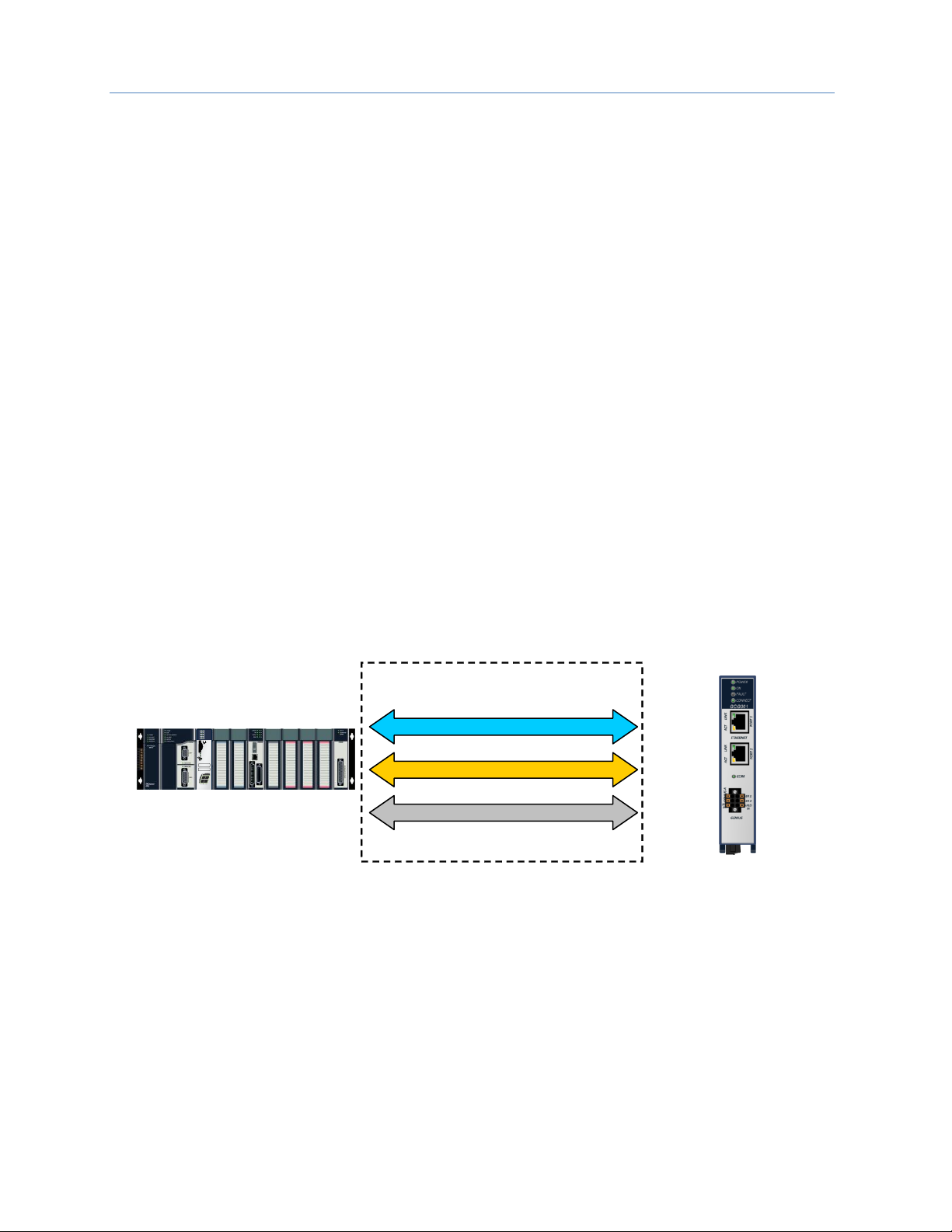
The following illustration represents an Application Relationship between an RX3i PROFINET Controller and an
RX3i Genius Gateway GCG001.
Record Data Communication Relationship
I/O Data Communication Relationship
Alarm Communication Relationship
Application Relationship
Genius Gateway (GCG001)
1
2
3
4
PNS001
ACTIVE
USB
OK
LAN
STATUS
CONN
USB
IP ADDRESS
MAC ADDRESS
PORTS
TO INSTALL,
TORQUE TO
6 IN-LB.
IO DEVICE
FRONT
3 4
1 2
SD CARD
!
RX3i with PROFINET Controller (PNC)
Figure 5: Application Relationships between PROFINET Controller & Genius Gateway
Chapter 1. Introduction
GFK-2892F March 2019 11
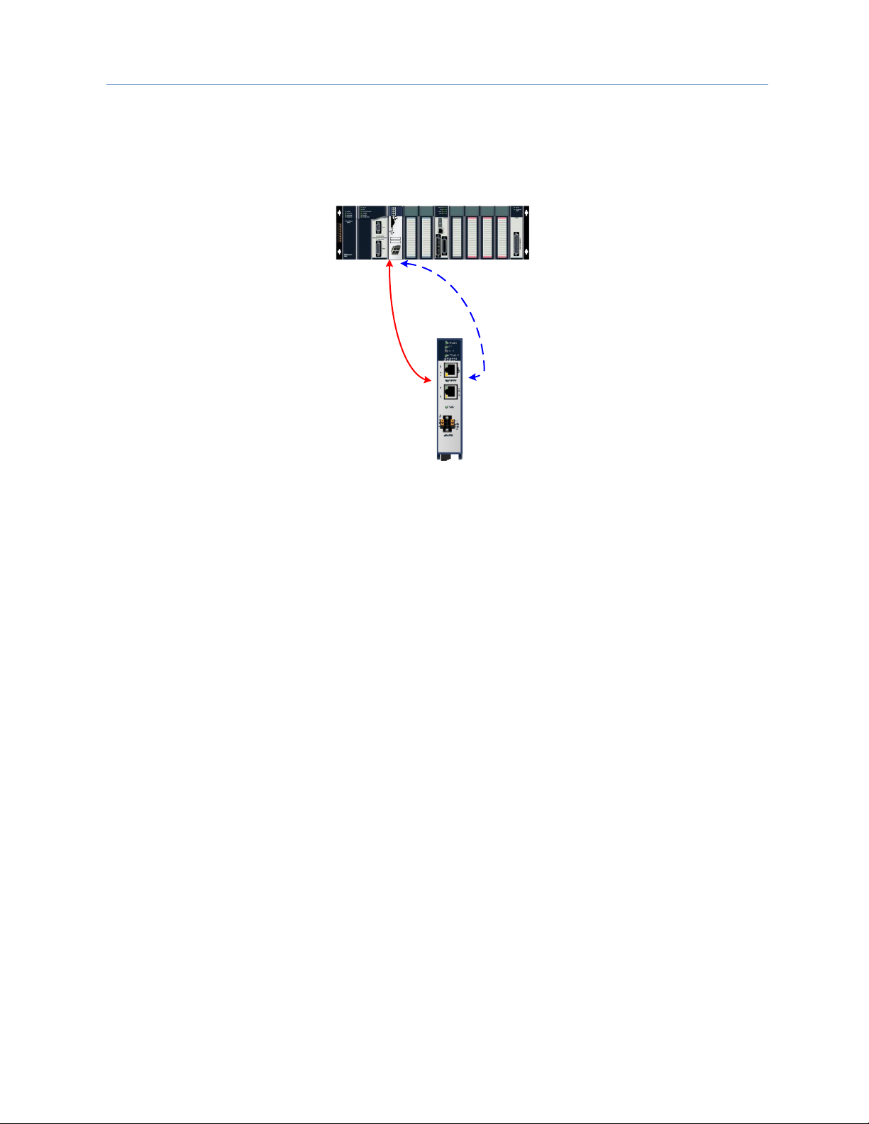
Types of PROFINET Communications
Genius Communications Gateways use two types of PROFINET communication transfers: real-time and nonreal-time. The illustration below shows real-time communications as solid lines and non-real-time
communications as dashed lines.
1
2
3
4
PNS001
ACTIVE
USB
OK
LAN
STATUS
CONN
USB
IP ADDRESS
MAC ADDRESS
PORTS
TO INSTALL,
TORQUE TO
6 IN-LB.
IO DEVICE
FRONT
3 4
1 2
SD CARD
!
RX3i with PROFINET Controller (PNC)
Real-Time Data
Inputs
Outputs
Alarms
Non Real-Time
Data
Parameters
Configuration Data
Figure 6: Real-Time & Non-Real-Time Data Types
Real-Time (RT) communication: PROFINET real-time communication is used for time-sensitive data. A
PROFINET IO-Controller (PROFINET Controller) and PROFINET IO-Device use two types of real-time
communications to exchange data: cyclic communication and acyclic communication:
Real-time Cyclic communication is used to periodically transfer the application’s input and output data. Cyclic
communication occurs each PROFINET IO production cycle.
Real-time Acyclic communication is used to transfer non-periodic data such as alarms. Acyclic communication
occurs only when needed.
Non-Real-Time (NRT) communication: PROFINET non-real-time communication is used for less timesensitive data such as configuration, parameterization, diagnostics, and identification data.
Operations of the Genius Communications Gateway
The Genius Communications Gateway performs the following operations:
Consumes PROFINET IO-Device configuration from the PROFINET IO-Controller over the PROFINET network.
Scans input data from each Genius device it manages and produces that data to the PROFINET IO-Controller.
Consumes the output data that it receives from the PROFINET IO-Controller and applies it to each Genius
device it manages.
Where needed, translates Genius Datagrams (background traffic) into PROFINET packages that are sent to the
PROFINET Controller. This includes Datagrams that originated at the Genius Devices, such as Fault Reports.
Translates PROFINET packages that are sent by the PROFINET Controller into Genius Datagrams. This includes
Datagrams that originated at the PLC through use of COMMREQ or Data_Init_Comm instructions. For example,
a COMMREQ is used to generate a Clear Fault Report datagram.
Chapter 1. Introduction
12 PACSystems RX3i Genius Communications Gateway GFK-2892F
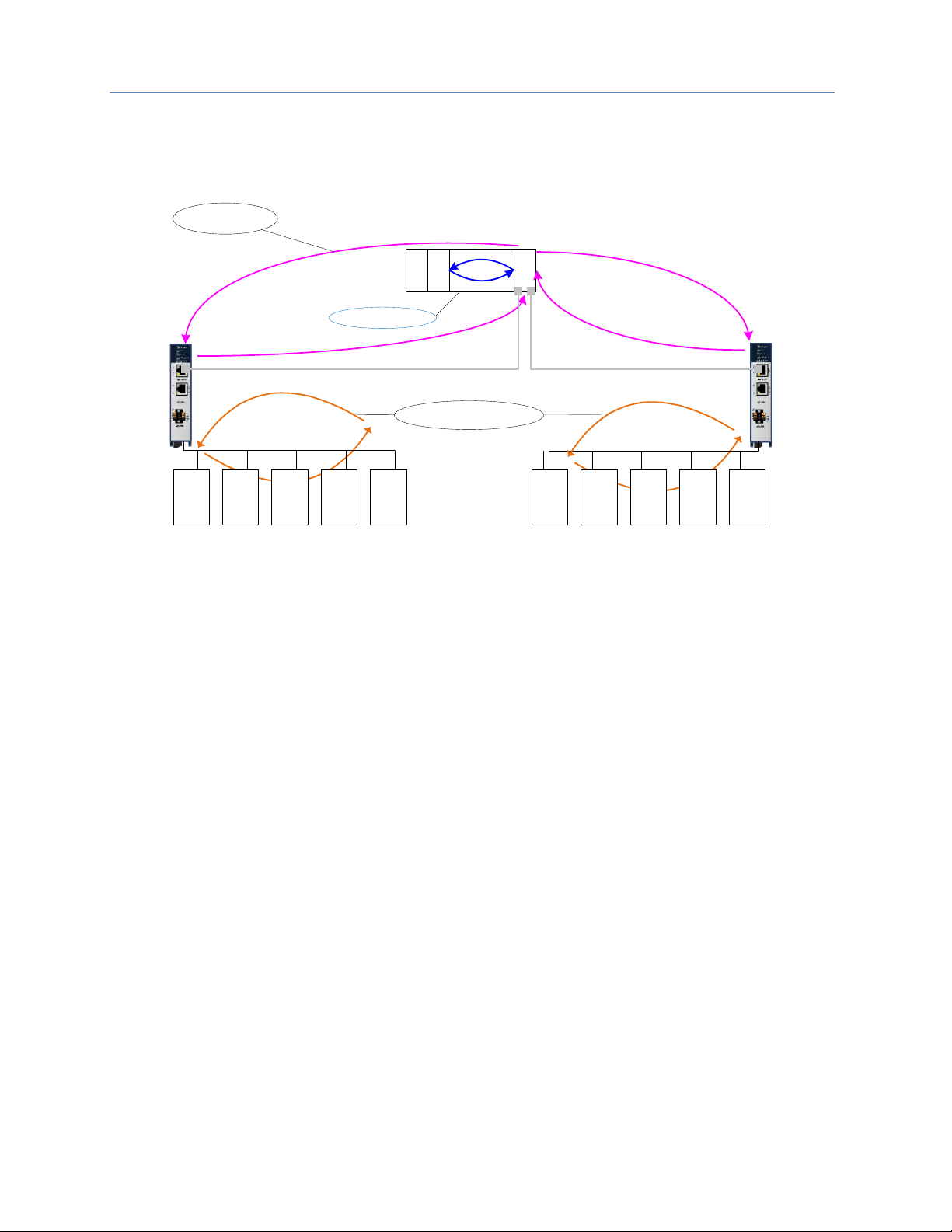
IO Scanning
In the PACSystems RX3i PROFINET network, multiple IO cycles run asynchronously and independently. Figure 7
illustrates typical cycles in a system with an RX3i CPU with a PROFINET Controller module communicating with
a Genius Communications Gateway. Cycles may be different for third-party devices.
Genius
I/O
Genius
I/O
Genius
I/O
Genius
I/O
Genius
I/O
PROFINET I/O
Genius
I/O
Genius
I/O
Genius
I/O
Genius
I/O
Genius
I/O
Genius Bus Scans
P
S
C
P
U
P
N
C
PROFINET IO
Production Cycle
RX3i CPU Sweep
Figure 7: PLC - GCG - Genius Scan Cycles
Genius IO-Device Scan: In this example, each GCG scans all of its Genius devices. The GCG stores the devices’
input data into its internal memory. Every time the GCG gets a turn on the Genius bus, it transmits the output
data from its internal memory to each of the Genius devices.
3rd party devices: The transfer of IO data between an IO module and the PROFINET IO network is device
dependent. Refer to the third-party manufacturer documentation for specifics for a particular device.
PROFINET IO Production Cycle: Each PROFINET Controller and IO-Device publishes data from its internal
memory onto the network at its scheduled PROFINET production cycle (Note: Production cycles between
IO-Controllers and IO-Devices are not synchronized; each publishes at its configured update rate
independently). The PROFINET Controller publishes output data received from the RX3i CPU to each IO-Device,
and the IO-Device publishes input data from its memory to the PROFINET Controller.
RX3i CPU Sweep: The RX3i CPU Sweep includes both an input scan and an output scan. The CPU input scan
retrieves the current input data being stored within the PROFINET Controller module. This input data is then
available for use by the application logic. After the logic solution, the CPU output scan writes the outputs to the
PROFINET Controller.

Chapter 1. Introduction
GFK-2892F March 2019 13
Media Redundancy Protocol Support
PROFINET Media Redundancy Protocol (MRP) supports devices configured in a ring topology. MRP is specified
as part of IEC62439 and has been adopted by the PROFINET specification, which provides for convenient
configuration of the ring topology and necessary parameters. Like PROFINET IO data, Media Redundancy
Protocol operations are not routable between different IP subnets.
Each device within an MRP ring has two physical pathways to the IO-Controller. To connect to the ring, each
device requires an integrated switch with at least two external ports (ring ports) that support MRP. Devices
that are not MRP-capable can be connected to a device in the ring (i.e., an MRP-capable switch in the ring), but
they should not be in the ring themselves. The redundancy capability offered by the ring topology only extends
to the devices on the ring that are MRP-capable and enabled.
One of the devices on the ring must be configured as the Media Redundancy Manager (MRM), and all the other
devices must be configured as Media Redundancy Clients (MRCs). The GCG001 can be configured as an MRC.
Configuring the GCG as an MRC alters how the Ethernet ports connect to the network. They attempt to
indicate their state to the MRM before allowing traffic to flow between the ports and close the ring topology
through the internal switch. They also send out notifications to the MRM when a port is lost. Operation of the
GCG001 is otherwise unchanged.
The MRP configuration is stored in non-volatile storage in the GCG001 and activated immediately upon
powering up. Non-volatile storage is updated as part of a connection with the IO-Controller. A PROFINET
Discovery & Configuration Protocol (DCP) Reset disables MRP Client operation and updates non-volatile
storage. The current state of the MRP configuration is provided as part of the GCG’s Gateway Status Bits which
are accessible to user application logic. Refer to the description of Gateway Status Bits in Section 5.1.1 for
further details.
Fast ring-break detection is not fully functional until all MRP clients have received their MRP configuration. For
a discussion of ring-break detection and bumpless operation with MRP, refer to sections 6.1.1 and 6.1.2 in the
PACSystems RX3i & RSTi-EP PROFINET I/O Controller Manual, GFK-2571K or later.

Chapter 1. Introduction
14 PACSystems RX3i Genius Communications Gateway GFK-2892F
1.9 System Limits
IO-Controllers have limitations on the size of the system they support. One of these limits is the number of
PROFINET sub-modules supported. The GCG001 uses four sub-modules: two for basic operation and two builtin port sub-modules that are always configured. Each Genius device attached to a GCG001 uses one additional
sub-module.
Other limitations, such as the configuration and IO sizes are specific to the configuration options chosen. Note
that not every combination of options is supported in every system. If the configuration uses all Genius bus
slots with a corresponding large device count, the memory of the IO-Controller system will be a limiting
resource.
Refer to the PACSystems RX3i & RSTi-EP PROFINET I/O Controller Manual, GFK-2571, for actual limits in the
RX3i PROFINET Controller (PNC001) and the embedded PROFINET controllers.
Refer to the Genius I/O System and Communications User's Manual, GEK-90486-1 for information on how
much I/O, and which type of I/O, need to be allocated to Genius devices.
PME (v8.0 or later) takes into account both system limits and I/O allocation.

Chapter 1. Introduction
GFK-2892F March 2019 15
1.10 Operational Differences vs. Genius Bus Controller
Persons migrating from a Genius environment where the Genius Bus Controller performs functions similar to
those of the GCG001 will want to be aware of the following differences:
1. COMMREQ function block SYSID and Task parameters change. SYSID is now the rack & slot of the
PNC connected to the GCG001. Task is now 132.
2. COMMREQ data blocks are different, mainly due to added PROFINET Device Number and
expansion of memory address fields from one word to two words. See COMMREQ summary in
Section 6.3.3.
3. Pulse Test and Assign Monitor COMMREQs do not support Genius bus address of 255 to send
messages to all blocks.
4. COMMREQ commands: GCG001 does not support all datagrams. See section 6.3.2 for a
corresponding list of supported COMMREQs.
5. GCG001 supports hot-standby, duplex, and dual-bus redundancy modes
1
. Dual-bus requires
additional application code.
6. GCG001 can be assigned to bus addresses 30 and 31 only.
7. GCG001 does not support GENI, GENA, or PCIM.
8. Prior to V1.1.1, fault contact operation has changed. Whenever there is a fault on a single channel
of a Genius block, all fault contacts associated with that Genius block will become active. All faults
on that device must be cleared before any of the fault contacts will de-energize. Beginning with
V1.1.1, when there is a fault on a single channel, none of the fault contacts will become active.
9. Genius faults routed through a GCG001 appear as PROFINET faults to the CPU. The same fault
routed through a Genius Bus Controller will present a different error code.
10. Circuit Fault Behavior:
• Prior to GCG firmware release V1.1.1, when a Genius block encounters a circuit fault on
one or more points or channels, the GCG001 causes all of the input references associated
with that block to either hold last state or go to default values until such time as the fault
is cleared. See the Alarms discussion in section 4.1.4 for a work-around to this behavior.
• Beginning with V1.1.1, when a Genius block encounters a circuit fault on one or more
points or channels, the GCG will cause only the faulted input references to hold the last
state or go to default values. The other points or channels on the block will continue to
operate normally.
11. Beginning with V2.2.2, Addition of Module and Loss of Module faults will not be logged when
Genius devices change their online status with the Genius bus. The user must monitor the 32 bits
of Genius Status Data to determine if Genius devices are operational or not.
12. Beginning with V2.2.4.1 Fault Status Bits are available to monitor each device on the bus. Refer to
Section 5.1.3 for additional information.
1
For Dual Bus Redundancy, GCG001 firmware version 2.2.0 or later is required; for all other redundancy modes, version
1.1.0 (minimum) is required.

Chapter 1. Introduction
16 PACSystems RX3i Genius Communications Gateway GFK-2892F
1.11 Supported Genius Devices
The following Genius devices are compatible with the GCG001 Genius Communications Gateway.
Catalog Number
Description
IC200GBI0012
VersaMax Genius Network Interface Unit (GNIU)
IC660BBA020
24/48Vdc 4-Input/2-Output Analog Block
IC660BBA021
24/48Vdc RTD Input Block
IC660BBA023
24/48Vdc Thermocouple Input Block
IC660BBA024
24/48Vdc Current–Source Analog Block
IC660BBA025
24/48Vdc Current–Source Output Block
IC660BBA026
24/48Vdc Current–Source Input Block
IC660BBA100
115Vac 4-Input/2-Output Analog Block
IC660BBA101
115Vac RTD Input Block
IC660BBA103
115Vac/125Vdc Thermocouple Input Block
IC660BBA104
115Vac/125Vdc Current–Source Analog Block
IC660BBA105
115Vac/125Vdc Current–Source Output Block
IC660BBA106
115Vac/125Vdc Current–Source Input Block
IC660BBD020
24/48Vdc 16-Circuit Source I/O Block
IC660BBD021
24/48Vdc 16-Circuit Sink I/O Block
IC660BBD022
24Vdc 16-Circuit Source I/O Block
IC660BBD023
24Vdc 16-Circuit Sink I/O Block
IC660BBD024
12/24Vdc 32-Circuit Source I/O Block
IC660BBD025
5/12/24Vdc 32-Circuit Sink I/O Block
IC660BBD1003
115Vac 8-Circuit Grouped Block
IC660BBD101
115Vac Low–Leakage 8-Circuit Grouped Block
IC660BBD110
115Vac 16-Circuit Input Block
IC660BBD120
High–Speed Counter Block
IC660BBR100
16-Circuit Relay Block, Normally–Closed
IC660BBR101
16-Circuit Relay Block, Normally–Open
IC660BBS100
115Vac/125Vdc 8-Circuit Isolated I/O Block
IC660BBS101
115Vac/125Vdc 8-Circuit Isolated I/O Block Without Failed Switch Diagnostic
IC660BBS102
115Vac/125Vdc 8-Circuit Isolated I/O Block
IC660BBS103
115Vac/125Vdc 8-Circuit Isolated I/O Block Without Failed Switch Diagnostic
IC670GBI002
IC670GBI102
Field Control Genius Bus Interface Unit (GBIU)
IC697BEM733 4
Series 90-70 Remote I/O Scanner (GR7)
2
Refer to VersaMax System Genius Network Interface Unit User’s Manual, GFK-1535, Chapter 1 for a list of VersaMax
modules supported by GBI001
3
Prior to GCG version 2.2.4.2, in PME Hardware Configuration, configure the BBD100 as a BBD101.
4
Refer to Series 90-70 Remote I/O Scanner User’s Manual, GFK–0579, Chapter 1 for a list of S90-70 modules supported by
BEM733.

GFK-2892F March 2019 17
Chapter 2 Installation
This chapter provides instructions for installing the module. The following topics are covered.
• Pre-Installation check
• Module installation and removal
• Port connections
• LED indications
• Firmware updates
For additional information about RX3i system installation, see the PACSystems RX3i System Manual, catalog
number GFK-2314.
For additional information about PROFINET installation and configuration, refer to the PACSystems RX3i &
RSTi-EP PROFINET I/O Controller Manual, GFK-2571. You will also need Proficy Machine Edition (PME)
configuration and programming software, version 8.0 or later.
2.1 Pre-Installation Check
Upon receiving your RX3i equipment, carefully inspect all shipping containers for damage. If any part of the
system is damaged, notify the carrier immediately. The damaged shipping container should be saved as
evidence for inspection by the carrier.
As the consignee, it is your responsibility to register a claim with the carrier for damage incurred during
shipment. GE Automation & Controls will cooperate fully with you, however, should such action be necessary.
After unpacking the RX3i equipment, record all serial numbers. Serial numbers are required if you should need
to contact Customer Care during the warranty period. All shipping containers and all packing material should
be saved should it be necessary to transport or ship any part of the system.
Verify that all components of the system have been received and that they agree with your order. If the system
received does not agree with your order, contact Customer Care.
If you need technical help, contact Technical Support. For phone numbers and email addresses, see the
Contact Information page in the front of this manual.
2.2 Installation Location
This product is primarily intended for use with the RX3i system. Its components are considered open
equipment (having live electrical parts that may be accessible to users) and must be installed in an ultimate
enclosure that is manufactured to provide safety. At a minimum, the enclosure shall provide a degree of
protection against solid objects as small as 12mm (e.g. fingers). This equates to a NEMA/UL Type 1 enclosure or
an IP20 rating (IEC 60529) providing at least a pollution degree 2 environment. For details about installing RX3i
rack systems, refer to the PACSystems RX3i System Manual, GFK-2314.
Chapter 2. Installation
18 PACSystems RX3i Genius Communications Gateway GFK-2892F
2.3 Installation in Hazardous Areas
The following information is for products bearing the UL marking for Hazardous Areas or ATEX marking for
explosive atmospheres:
CLASS 1 DIVISION 2 GROUPS ABCD
• This equipment is an open-type device and is meant to be installed in an enclosure
suitable for the environment that is only accessible with the use of a tool.
• Suitable for use in Class I, Division 2, Groups A, B, C and D Hazardous Locations, or
nonhazardous locations only.
Warning
EXPLOSION HAZARD - SUBSTITUTION OF COMPONENTS MAY
IMPAIR SUITABILITY FOR CLASS I, DIVISION 2.
WHEN IN HAZARDOUS LOCATIONS, TURN OFF POWER BEFORE
REPLACING OR WIRING MODULES; AND
DO NOT CONNECT OR DISCONNECT EQUIPMENT UNLESS
POWER HAS BEEN SWITCHED OFF OR THE AREA IS KNOWN TO
BE NONHAZARDOUS.
Warning
EXPLOSION HAZARD - USB PORT IS ONLY FOR USE IN
NONHAZARDOUS LOCATIONS, DO NOT USE UNLESS AREA IS
KNOWN TO BE NON-HAZARDOUS.
ATEX Zone 2
The module must be mounted in an enclosure certified in accordance with EN60079-15 for use in Zone 2,
Group IIC and rated IP54. The enclosure shall only be able to be opened with the use of a tool.
ATEX Marking
II 3 G Ex nA IIC T4 X Ta: 0 - 60C
Chapter 2. Installation
GFK-2892F March 2019 19
2.4 Module Installation
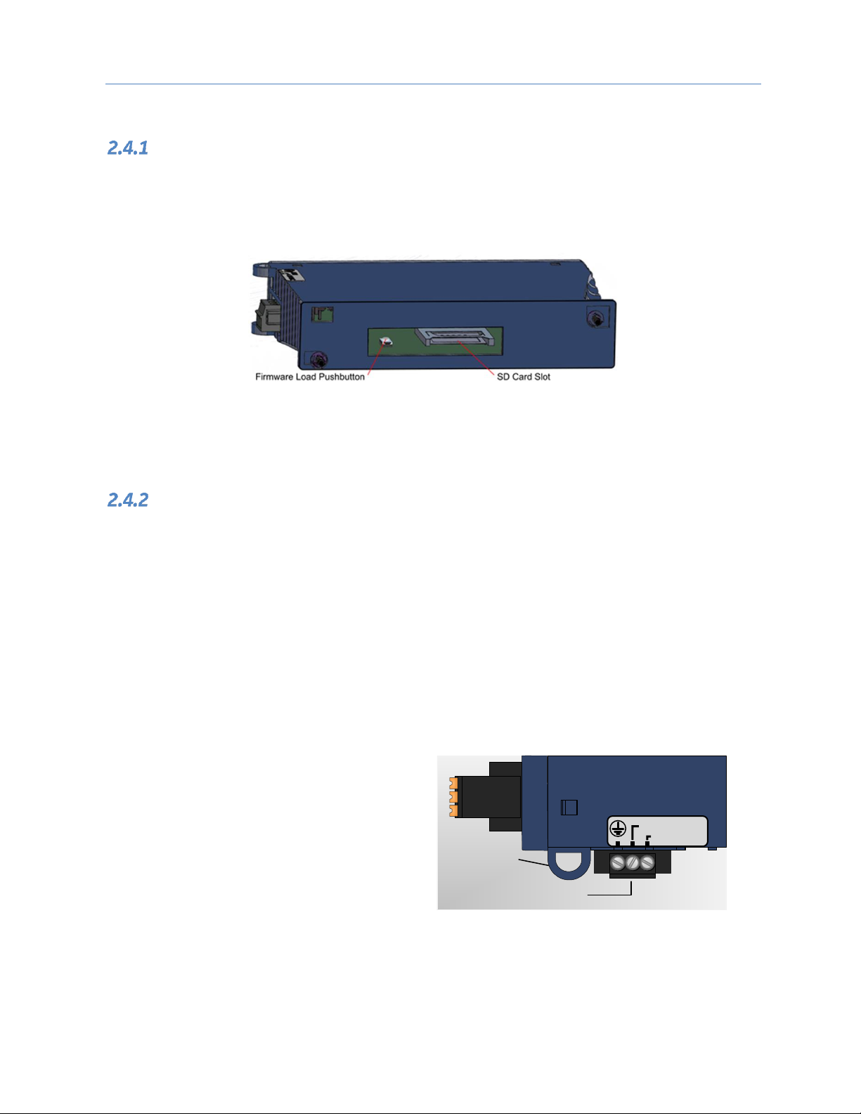
Install SD Card
The SD card slot is designed to support a Secure Digital (SD) non-volatile memory card in standard capacity
format. This optional card has two distinct uses: (1) backup storage of some key PROFINET configuration data
and (2) loading new GCG001 module firmware. Insert the SD Card into its slot at the rear of the GCG001 before
mounting the module, as shown in Figure 8.
Figure 8: Rear View of GCG001
When shipped from the factory, the SD card will have been pre-installed. It will have been programmed with
the then-current version of the firmware for the GCG001. In the event the firmware on the SD card needs to be
updated, see section 2.7. Note that the firmware upgrade should be performed before mounting the module.
Mounting the GCG001
The GCG001 is designed to mounted in one of the following ways:
a. In the expansion slot of an RX3i Universal Backplane
b. Panel-mounted
In both cases, at least 75 mm (3 in.) must remain clear above and below the module to allow for convection
cooling. See section 1.7.1 for mounting details.
Once the module has been mounted, connect 24Vdc power via the connector on the underside of the module,
connect PROFINET via the RJ-45 connectors and the Genius bus via twisted pair cable. Each connection is
described in the following section.
Once all connections are in place, it will be necessary to configure PROFINET. This is also discussed in the
following sections
Power Connection
The module requires a user-supplied 24Vdc
(±10%) power source wired to the removable
screw-terminal block located on the bottom of
the module. Connector pin-outs are identified
on the module, as indicated at right. The
module draws 0.2 A maximum current.
+24 VDC
RTN
24 Vdc Power
Connector
(Use for cable
tie-downs)
Figure 9: GCG001 Power Connector
Chapter 2. Installation
20 PACSystems RX3i Genius Communications Gateway GFK-2892F
Grounding
For proper operation, always connect the GCG001 ground terminal (see Figure 9, above) to earth ground. The
panel to which the GCG001 module is mounted, or the RX3i Universal Backplane to which it is mounted, must
have a safety ground connection to protective earth. This ground wire must be at least 1.5 mm2 (16 AWG).
• Connect the frame ground connection on the power plug to protective earth.
• Terminate all ground wires at the same grounding point.
• Make all ground wires as short as possible.
• Where the grounding terminal contacts a painted enclosure panel, scrape the paint away down to
clean, bare metal to ensure good contact.
PROFINET Connection
Attach the PROFINET via one or both of the RJ-45 connectors provided (Port 1 & Port 2). Various configurations
are possible. Refer to the manual for the PROFINET controller used in the application (PACSystems RX3i &
RSTi-EP PROFINET I/O Controller Manual, GFK-2571 for the RX3i PROFINET Controller Module).
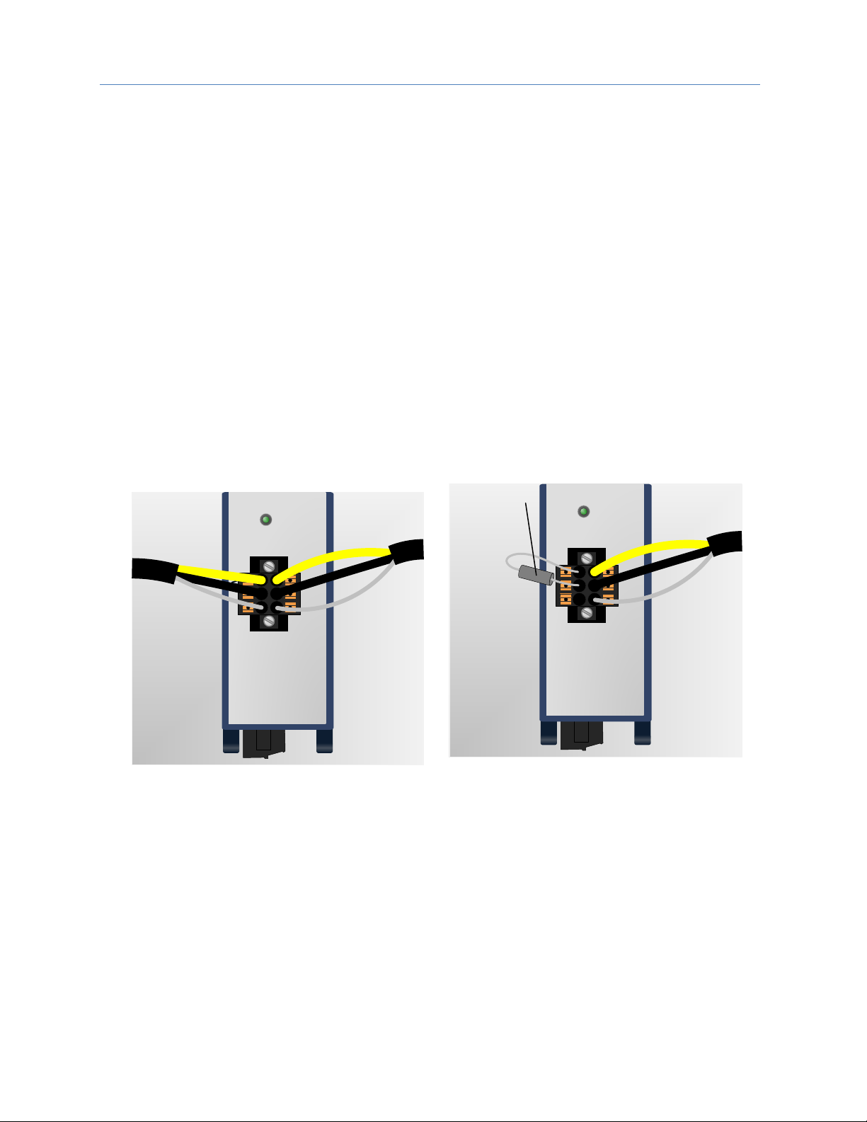
Genius Bus Connection
The GCG module is equipped with one active six-terminal Genius Serial Bus connector.
Two terminals each are provided on a removable terminal block for Serial 1, Serial 2, and Shield connections.
The figure (above left) shows the Genius connection continuing through the connector block (daisy chain).
Whenever the Genius bus is terminated at the GCG001, a bus termination resistor should connect Serial 1 to
Serial 2, with SHLD IN unterminated, (as shown above right). The value of the termination resistor must match
the impedance of the Genius Bus cable.
Note: Whenever the GCG001 Genius terminal blocks are removed from the faceplate, the
continuity of the Genius Bus is disrupted.
COM
GENIUS A
SER 1
SER 2
SHLD
IN
GENIUS
SHLD
OUT
Figure 10: Daisy Chain Genius Bus Wiring
COM
GENIUS A
SER 1
SER 2
SHLD
IN
GENIUS
SHLD
OUT
Bus
termination
resistor
Figure 11: Genius Bus Wiring for Bus
Termination
Chapter 2. Installation
GFK-2892F March 2019 21
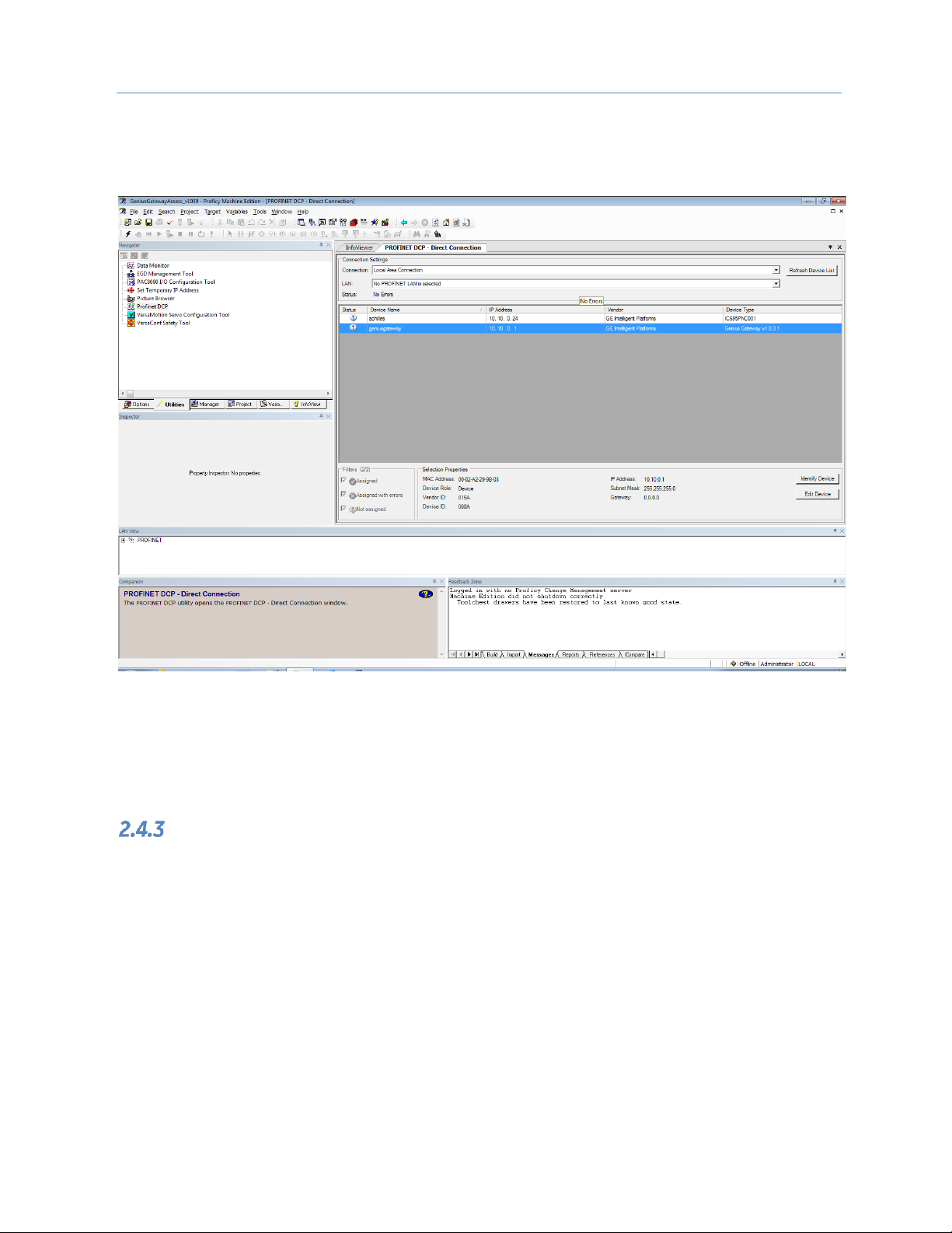
PROFINET Configuration
Once all connections are in place, it will be necessary to set up the PROFINET configuration. This requires use
of the PC-based PROFINET Discovery tool. Be sure your PC is connected to the same PROFINET network and
interrogate the network to discover what is connected, as shown in the following screen-shot.
Figure 12: PROFINET Discovery Screenshot
Initially, the out-of-the box GCG001 will not have a name assigned. Select the row containing the GCG001, then
click on the Edit Device button in order to assign a unique name.
Configuration tools and procedures are discussed in detail in Chapter 3.
GCG001 Module Removal
• Power down the external 24Vdc source
• Remove the Power connector from the underside of the GCG001 module
• Disconnect the RJ-45 PROFNET connector(s)
• Remove the Genius terminal block
• While holding the GCG001, loosen the two captive M3.5 screws that hold the module
in place, then pull away from the mounting surface. Note that, if mounted to an RX3i
rack, there is no pivot attachment or backplane connection to the rack.
• The SD Card may be transferred from the removed GCG001 to another (successor)
GCG001. This permits the PROFINET configuration of the removed module to be
transferred to the successor module.
• Once the successor module has been mounted, the original Power, PROFINET and
Genius connections may be restored to it.
 Loading...