

Page 1

GE Fanuc Automation
Programmable Control Products
TCP/IP Ethernet Communications
for the Series 90™ PLC
User's Manual
GFK-1541B May 2002
Page 2

Warnings, Cautions, and Notes
as Used in this Publication
Warning
Warning notices are used in this publication to emphasize that hazardous voltages,
currents, temperatures, or other conditions that could cause personal injury exist in this
equipment or may be associated with its use.
In situations where inattention could cause either personal injury or damage to
equipment, a Warning notice is used.
Caution
Caution notices are used where equipment might be damaged if care is not taken.
Note
Notes merely call attention to information that is especially significant to understanding and
operating the equipment.
GFL-002
This document is based on information available at the time of its publication. While efforts
have been made to be accurate, the information contained herein does not purport to cover all
details or variations in hardware or software, nor to provide for every possible contingency in
connection with installation, operation, or maintenance. Features may be described herein
which are not present in all hardware and software systems. GE Fanuc Automation assumes no
obligation of notice to holders of this document with respect to changes subsequently made.
GE Fanuc Automation makes no representation or warranty, expressed, implied, or statutory
with respect to, and assumes no responsibility for the accuracy, completeness, sufficiency, or
usefulness of the information contained herein. No warranties of merchantability or fitness for
purpose shall apply.
The following are trademarks of GE Fanuc Automation North America, Inc.
Alarm Master Genius PowerTRAC Series Six
CIMPLICITY Helpmate ProLoop Series Three
CIMPLICITY 90–ADS Logicmaster PROMACRO VersaMax
CIMSTAR Modelmaster Series Five VersaPoint
Field Control Motion Mate Series 90 VersaPro
GEnet PowerMotion Series One VuMaster
Workmaster
©Copyright 2002 GE Fanuc Automation North America, Inc.
All Rights Reserved.
Page 3

Contents
Chapter 1
Chapter 2
Chapter 3
Chapter 4
Introduction .........................................................................................................1-1
The Ethernet Interface.......................................................................................................1-2
Ethernet Interface Ports.....................................................................................................1-4
The Station Manager Software .........................................................................................1-7
Installation ...........................................................................................................2-1
Installing an IC693CMM321 Ethernet Interface Module................................................. 2-2
Installing an IC693CPU364 with Embedded TCP/IP Ethernet Interface .......................2-16
Installing an IC693 CPU374 with Embedded TCP/IP Ethernet Interface ......................2-30
Installing the IC697CMM742 Ethernet Interface ........................................................... 2-41
Programming SRTP Channel Commands........................................................3-1
The Communications Request .......................................................................................... 3-2
COMMREQ Function Block and Command Block .........................................................3-6
Channel Commands.......................................................................................................... 3-9
Status Data ......................................................................................................................3-31
Controlling Communications in the Ladder Program..................................................... 3-43
Programming Modbus/TCP Channel Commands...........................................4-1
Chapter 5
Chapter 6
The Communications Request .......................................................................................... 4-2
COMMREQ Function Block and Command Block .........................................................4-5
Modbus TCP Channel Commands.................................................................................... 4-8
Status Data ...................................................................................................................... 4-20
Controlling Communications in the Ladder Program..................................................... 4-26
Ethernet Global Data .......................................................................................... 5-1
Overview of EGD ............................................................................................................. 5-2
Configuring EGD............................................................................................................ 5-12
Adapter Names, Aliases, and Groups .............................................................................5-21
Exchange Status Word.................................................................................................... 5-23
Simple Network Time Protocol (SNTP)......................................................................... 5-25
Network Administration Support......................................................................6-1
IP Addressing.................................................................................................................... 6-2
Gateways........................................................................................................................... 6-4
Subnets and Multiple Gateways........................................................................................ 6-5
Configuring Multiple Gateways........................................................................................ 6-7
Network Address Naming Architecture............................................................................ 6-9
GFK-1541B iii
Page 4

Contents
Chapter 7
Troubleshooting...................................................................................................7-1
Diagnostic Tools Available for Troubleshooting.............................................................. 7-2
What to do if you Cannot Solve the Problem ...................................................................7-3
PLC Fault Table................................................................................................................ 7-4
Appendix A Glossary............................................................................................................... A-1
Appendix B Communications Port Characteristics ............................................................. B-1
RS-232, RJ-11 Serial Port................................................................................................ B-2
RS-485, 15-Pin, D-Type Port........................................................................................... B-4
10Base-T Port .................................................................................................................. B-6
10Base-T/100Base Tx Port .............................................................................................. B-8
10Base2 Port .................................................................................................................. B-11
AAUI Port...................................................................................................................... B-13
AUI Port......................................................................................................................... B-19
Appendix C PC Software Loader........................................................................................... C-1
Updating Firmware Under Windows............................................................................... C-2
Updating Firmware Under DOS and Windows 3.xx ....................................................... C-4
Appendix D Using the IC697CMM742 with PLC CPU Versions 4.12 - 5.50 ..................... D-1
Ethernet Interface Operational Restrictions..................................................................... D-6
Appendix E Translating PLC CPU Reference Addresses to Modbus Register Addresses
for the IC693CMM321....................................................................................... E-1
iv TCP/IP Ethernet Communications for the Series 90™ PLC User's Manual– May 2002 GFK-1541B
Page 5

Contents
GFK-1541B Contents v
Page 6

Chapter
1
Introduction
This manual describes the following
Series 90-30 PLC TCP/IP Ethernet Interface (IC693CMM321)
Series 90-30 PLC CPU364 with embedded TCP/IP Ethernet Interface (IC693CPU364)
Series 90-30 PLC CPU374 with embedded TCP/IP Ethernet Interface (IC693CPU374)
Series 90-70 PLC TCP/IP Ethernet Interface (Type 2) (IC697CMM742)
The general term,
Interfaces require the more specific terms.
The Series 90-30 PLC CPU 364 and CPU374 are both modules that contain a PLC CPU and an
embedded Ethernet Interface. The general term Embedded Ethernet Interface will be used in this
manual to refer to these modules.
This chapter provides an overview of the Ethernet Interface and covers the following topics:
The Ethernet Interface
How to Make the System Work
Quick Guide to the Manual
Ethernet Interface
Ethernet Interfaces
, will be used in this manual except when differences in the
for the Series 90 PLC:
GFK-1541B 1-1
Page 7
1
g
The Ethernet Interface
The Ethernet Interface enables Series 90 PLCs to communicate with other Series 90 PLCs, with
with GE Fanuc PLC programming software, and with applications developed using the SRTP
protocol, such as CIMPLICITY® HMI.
The Ethernet Interfaces described in this manual have “client/server” capability. As a “client” the
Interfaces can initiate communications with other Series 90 PLCs containing Ethernet Interfaces.
This is done from the PLC ladder program using the COMMREQ function. As a “server” the
Interfaces respond to requests from other devices such as PLC programming software, a Host
computer running an SRTP application, or another Series 90 PLC acting as a “client”. No PLC
programming is required for server operation.
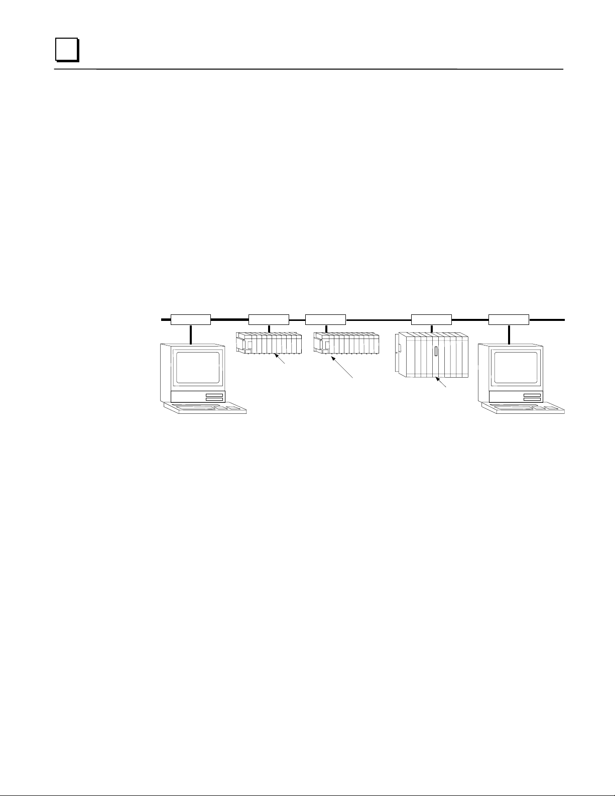
Ethernet Communications System
The diagram below represents a basic Ethernet Communications system.
Ethernet
Transceiver
Network
Connection
Cable
Transceiver
TransceiverTransceiver
Transceiver
Network
Connection
Series 90-30
CPU 364 or 374
with Embedded
Ethernet Interface
Host Computer or
Control Device Running an
SRTP Application
Series 90-30
PLC
Ethernet
Interface
® Windows is a registered trademark of Microsoft Corporation.
PLC
Series 90-70
PLC
Ethernet
Interface
Pro
rammer
1-2 TCP/IP Ethernet Communications for the Series 90™ PLC User's Manual – May 2002 GFK-1541B
Page 8

Capabilities of the Ethernet Interface
The Ethernet Interface brings to your PLC a great deal of capability. It will allow you to:
Become operational quickly. The Ethernet Interface is made operational with very little effort.
You need only install the Interface in the PLC rack or baseplate and use the PLC
programming software to store basic configuration information to the module to make the
basic SRTP server capability functional. SRTP Client capability, the capability to initiate
communications, can be added using the COMMREQ function in the ladder program. For
Series 90-30 Ethernet Interface IC693CMM321-FH and later, basic Modbus/TCP server
capability is available as soon you supply basic configuration information to the module, and
you can use COMMREQs to initiate Modbus/TCP communications.
Directly attach your PLC to an Ethernet network. The Ethernet Interface allows you to directly
attach the Series 90 PLC to an Ethernet LAN via the built-in network ports or via a usersupplied transceiver and AUI or AAUI cable, and to communicate with host computers and
other Series 90 PLCs on the local network.
Ethernet Global Data. (Series 90-30 CPU364 and CPU374 and Series 90-70 Ethernet
Interface (Type 2) only.) When used with the latest Series 90 CPUs, the Ethernet Interface
provides highly efficient periodic data transfer between PLCs using Ethernet Global Data
exchanges.
Transfer data between PLCs.
to initiate communications to other Series 90 Ethernet Interfaces, using COMMREQ
functions in the ladder program.
Access data using a Host computer.
access data within the Series 90 PLC through the server capability of the Ethernet Interface. .
Communicate simultaneously to multiple devices. The multiplexing capabilities of the
Ethernet Interface, along with Ethernet network’s high capacity, allow the PLC to
communicate with several other devices at the same time.
Maintain compatibility with other GE Fanuc devices and devices from other vendors. The
Series 90-30 Ethernet Interface, Series 90-30 CPU364 Embedded Ethernet Interface, Series
90-30 CPU374 Embedded Ethernet Interface, and Series 90-70 Ethernet Interface (Type 2)
are compatible with each other. They are also compatible with GE Fanuc programming
packages supporting TCP/IP Ethernet communications.
Diagnose and maintain your system, using diagnostic and station management tools. You can
find problems before they become serious. In the event that communications software
upgrades are needed, you can use a built-in serial port to download the software to the
Ethernet Interface.
Indirectly attach to other Local Area Networks and/or wide area networks via third party IP
routers.
When configured to use an IP gateway (router), the Ethernet Interface can
communicate with remote PLCs and other nodes reachable through the router.
Communicate with remote computers via Serial Line Protocol (SLIP) using modems and/or
serial lines. Using third party SLIP software, a remote host computer can be attached to a
TCP/IP network.
Communicate with other Series 90 PLCs using symbolic names as well as IP addresses.
COMMREQs can be programmed to communicate with PLCs using IP addresses or Network
Address names (Series 90-30 Ethernet Interface, Series 90-30 CPU364 Embedded Ethernet
Interface, and Series 90-70 Ethernet Interface (Type 2)).
The Ethernet Interface provides client capability, the capability
Computer applications which use the SRTP protocol can
1
®Windows and Windows NT are registered trademarks of Microsoft Corporation.
GFK-1541B Chapter 1 Introduction 1-3
Page 9

1
Ethernet Interface Ports
The Ethernet Interfaces provide ports for connection to the Ethernet network as listed below.
IC693CMM321 Series 90-30 TCP/IP
Ethernet Interface
IC693CPU364 Series 90-30 CPU with
Embedded TCP/IP Ethernet Interface
IC693CPU374 Series 90-30 CPU with
Embedded TCP/IP Ethernet Interface
IC697CMM742 Series 90-70 TCP/IP
Ethernet Interface (Type 2)
Port Descriptions
AAUI Port
10Base-T Port (RJ-45) (Module version
FG or later)
AAUI Port
10Base-T Port (RJ-45)
Auto-sensing 10Base-T Port (RJ-45)
10Base-T Port (RJ-45)
AUI Port
10Base2 Port (BNC)
10Base-T, RJ-45 port
and Series 90-70 IC697CMM742 Ethernet Interface (Type 2))
The 10Base-T port uses a twisted pair cable of up to 100 meters in length between each node and
a hub or repeater. Typical hubs or repeaters support 6 to 12 nodes connected in a star wiring
topology.
Auto-sensing 10 Base T / 100 Base TX, RJ-45 Port
The auto-sensing 10 Base T / 100Base TX ports are connected to a switch device embedded in the
Ethernet Interface. They use a twisted pair cable (unshielded or shielded) of up to 100 meters in
length between the node and another node, a hub, a repeater, or a switch. The port automatically
senses the speed (10Mbps or 100Mbps), duplex mode (half duplex or full duplex) and cable
(straight-through or crossover) attached to it with no intervention required.
10Base2, BNC port
The 10Base2 port uses a 0.2 inch diameter 50-ohm coaxial cable and is commonly called “thin
wire”. The maximum length of a cable segment is 185 meters. A maximum of 30 stations is
allowed on a 10Base2 Ethernet segment.
AUI Port
AAUI Port
The AUI and AAUI ports provide the electrical and mechanical interface to the user-provided
Ethernet transceiver cable, which connects the AUI or AAUI port to an external user-provided
transceiver. (The transceiver cable may be separate or built-in to the transceiver.) The external
transceiver is directly connected to the Ethernet cable.
(
Series 90-70 Ethernet Interface (Type 2))
(
Series 90-30 Ethernet Interface (AAUI-only Type) and Series 90-30 CPU364)
(Series 90-30 Ethernet Interface (10Base-T Type), Series 90-30 CPU364,
(Series 90-30 CPU374 only)
(Series 90-70 Ethernet Interface (Type 2))
and
1-4 TCP/IP Ethernet Communications for the Series 90™ PLC User's Manual – May 2002 GFK-1541B
Page 10

Ethernet Media
Various Ethernet baseband media (10Base...) can be interconnected by appropriate hubs or
repeaters. Capabilities and limitations are defined in IEEE 802.3 Chapter 13, “System
Considerations for Multi-Segment Networks”. This document is published by the Institute of
Electrical and Electronics Engineers, Inc., 345 East 47th Street, New York, NY 10017-2394 USA.
The Ethernet Interface can operate on any of the following media with the appropriate usersupplied transceiver cable and transceiver. IEEE 802.3 specifies the definitive requirements of
each medium.
1
10Base5 Coax:
“thick wire”. The maximum length of a cable segment is 500 meters. The distance between any
two stations must be a multiple of 2.5 meters. A maximum of 100 stations is allowed on a
10Base5 Ethernet segment.
10Base2 Coax:
10Base-T:
10Base-F:
10Base-FP can support up to 33 nodes at distances of up to 500 meters from a passive star;
10Base-FL supports up to 2000 meters between a node and a repeater (a multi-port repeater
would thus constitute a star). Additionally, 10Base-FB provides a means of interconnecting
(only) repeaters by up to 2000 meters of (the same) fiber-optic cable.
10Broad36:
amplifiers, headend translators, etc.) to support hundreds of nodes at distances of up to 2800
meters. Broadband cannot be connected to baseband via repeaters. Broadband cable plant design
and installation must be in accordance with IEEE 802.7 and requires special expertise. GE Fanuc
recommends you contract professional specialists for these services. Consult your GE Fanuc
sales representative or field service office for help in identifying local specialists.
10Base5 uses a 0.4 inch diameter 50-ohm coaxial cable and is commonly called
10Base2 is described above.
10Base-T is described above.
10Base-F has two variations that both use the same type of fiber-optic cable.
10Broad36 uses 75-ohm coaxial cable and CATV-like media components (taps,
GFK-1541B Chapter 1 Introduction 1-5
Page 11
1
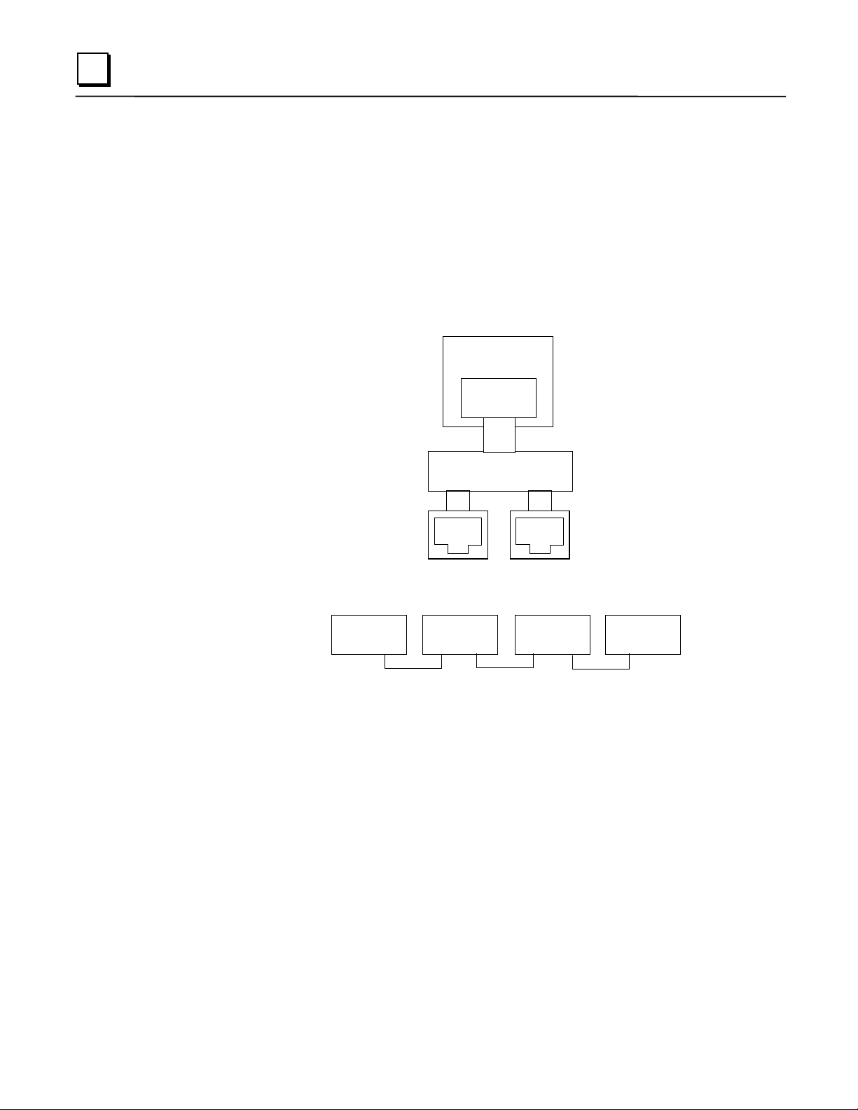
Special Considerations for Ethernet Interfaces with Embedded Switches
Ethernet Interfaces that incorporate embedded switches (only the Series 90-30 CPU374) provide
some additional connection options and have some additional installation and operation
considerations.
These Ethernet Interfaces provide two RJ-45 connectors on the front of the module. It is
important to realize that there is only one interface to the network (only one Ethernet address and
only one IP address) provided by these Ethernet Interfaces. The two connectors allow up to two
Ethernet devices (hubs, switches, other PLCs, PCs) to be connected to the Ethernet Interface. This
arrangement is diagrammed below.
90-30 CPU374
Ethernet
Processor
Ethernet
MAC
10/100 Network
Switch
Port 1 Port 2
For simple installations, the embedded switch allows PLCs and other devices to be connected
together without requiring any additional components.
Operator
Interface
PLC PLC
Personal
Computer
It is also possible to daisy-chain PLCs together without additional components, but that should be
done with great care. In designing a system, remember that a loss of power or reset on any
Ethernet Interface in a daisy chain will cause loss of communications with all devices
downstream from the lost module.
The second port, if left unused, can be used to plug in a programmer over Ethernet.
Caution
The two ports on the Ethernet Interface must not be connected, either directly or indirectly,
to the same device. The hub or switch connections in an Ethernet network must form a tree,
otherwise duplication of packets may result.
1-6 TCP/IP Ethernet Communications for the Series 90™ PLC User's Manual – May 2002 GFK-1541B
Page 12

The Station Manager Software
The built-in Station Manager software provides on-line supervisory access to the Ethernet
Interface, through either the Station Manager port or over the Ethernet cable. The Station
Manager services on the Ethernet Interface include:
An interactive set of commands for interrogating and controlling the station.
Unrestricted access to observe internal statistics, an exception log, and configuration
parameters.
Password security for commands that change station parameters or operation.
Access to the Station Manager is attained through a user-provided computer terminal or terminal
emulator. See GFK-1186,
Manager Manual
, for more information on the Station Manager.
The PC Software Loader
The PC Software Loader is a separate software utility which runs on a PC in order to update the
communications software stored in flash memory in the Ethernet Interface. This utility is
supplied with any updates to the Ethernet Interface software.
TCP/IP Ethernet Communications for the Series 90 PLC Station
1
How to Make the System Work
There are only a few simple tasks required to get your Ethernet communications system working.
These tasks are addressed in detail later in this manual.
1. Install the Ethernet Interface into the Series 90 rack or baseplate and connect it to the
network.
2. Power-up the PLC.
3. Configure the Ethernet Interface using the PLC programming software and store to the PLC.
4. To add optional SRTP client capability, refer to Chapter 3 “Programming SRTP Channel
Commands” . To add optional Modbus/TCP client capability (Series 90-30 Ethernet
Interface IC693CMM321-FH or later only), refer to Chapter 4 “Programming Modbus/TCP
Channel Commands”. To configure or program Ethernet Global Data, refer to Chapter 6,
“Ethernet Global Data”.
GFK-1541B Chapter 1 Introduction 1-7
Page 13

1
1-8 TCP/IP Ethernet Communications for the Series 90™ PLC User's Manual – May 2002 GFK-1541B
Page 14

Chapter
2
Installation
This chapter contains installation instructions for each Series 90 module that includes an Ethernet
Interface.
Section 1: IC693CMM321 Series 90-30 TCP/IP Ethernet Interface (10Base-T type)
Section 2: IC693CPU364 Series 90-30 CPU with Embedded TCP/IP Ethernet Interface
Section 3: IC693CPU374 Series 90-30 CPU with Embedded TCP/IP Ethernet Interface
Section 4: IC697CMM742 Series 90-70 TCP/IP Ethernet Interface
Each section covers the basic features of the Ethernet Interface, its installation, configuration, and
a procedure for its initial checkout on your Ethernet cable. Each section first provides a hardware
overview of the Ethernet Interface and is then divided into four Installation Procedures, each
providing an overview of the procedure and then explaining the detailed steps to be performed.
The installation procedures described for each Ethernet Interface are:
Installing the Ethernet Interface in the PLC - Required
Configuring the Ethernet Interface - Required
Verifying Proper Power-Up of the Ethernet Interface - Required
“Pinging” the Ethernet Interfaces on the Network - Optional
Some of the procedures require prior Ethernet cable plant design and installation.
GFK-1541B 2-1
Page 15
2
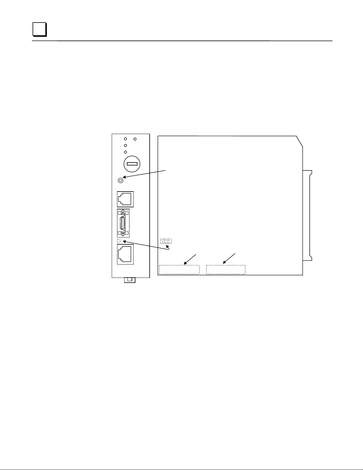
Installing an IC693CMM321 Ethernet Interface Module
The IC693CMM321Ethernet Interface mounts in a Series 90-30 PLC baseplate. It connects to an
Ethernet network either directly through its 10Base-T port (10Base-T Type only), or through its
AAUI port, which requires a user-provided transceiver and cable. If using the AAUI port, you
may order a transceiver from GE Fanuc (see Appendix B for information) or supply your own
equivalent transceiver. .
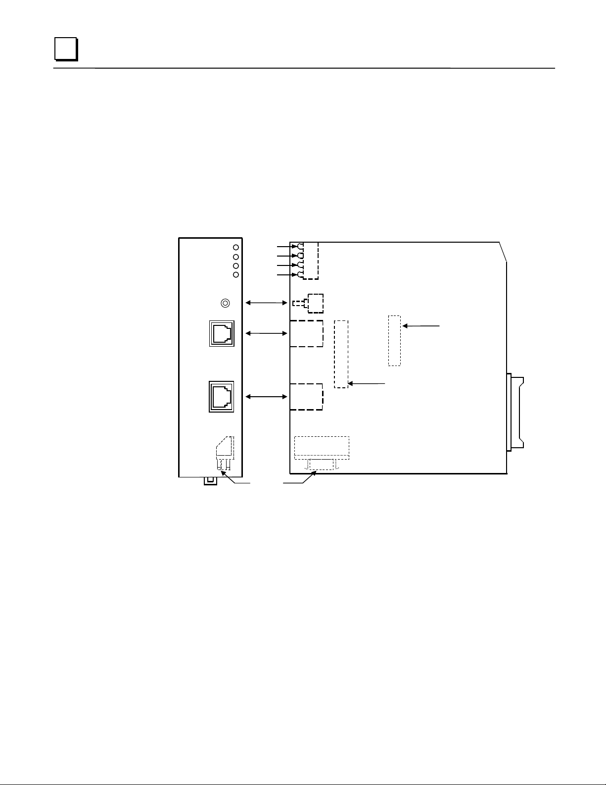
IC693CMM321 Series 90-30 TCP/IP Ethernet Interface (10Base-T Type)
CMM321 versions EF or earlier do not have a 10Base T port.
CMM321
ETHERNET
INTERFACE
ETHERNET
RESTART
STATION
MGR
RS-232
10BASE-T
OK
LAN
FDX
STAT
OK
LAN
FDX
STAT
RESTART
PUSHBUTTON
RS-232 STATION
MANAGER
PORT (RJ-11)
10BASE-T
PORT (RJ-45)
AAUI PORT
Serial Number
Label (Internal)
Default Station
Address Label
(Internal)
This module has several user-accessible features:
Four LEDs are located at the top of the board.
The Restart pushbutton is located immediately below the LEDs.
The Station Manager port (RS-232 serial port with an RJ-11 connector) is located on the front
of the module.
The 10Base-T Ethernet port (RJ-45 connector) is located on the front of the module. It does
not require an external transceiver.
The AAUI port (14-pin AAUI connector) is accessible through an opening in the bottom of
the module. It requires an external transceiver.
The Default Station Address label lists the MAC address to be used by this Interface. It is
located by removing the module’s front cover and looking on the circuit board.
The module’s serial number is on the silver label on the left side of the module.
2-2 TCP/IP Ethernet Communications for the Series 90™ PLC User's Manual – May 2002 GFK-1541B
Page 16

LEDs
There are four LEDs on the CMM321 module. Each of these LEDs can be ON, OFF, or
BLINKING.
LED Indication Function
OK State of the Ethernet Interface
LAN Traffic on the network port
FDX Configuration of Full Duplex mode.
STAT An exception event has occurred
All LEDs are briefly turned ON whenever a restart is performed in the Operational state by
pressing and releasing the Restart pushbutton (described below). This allows you to verify that all
LEDs are operational. (On module versions EF or earlier, the FDX LED is labeled "SER".)
Restart Pushbutton
The Restart pushbutton serves four functions: LED test, Restart, Restart and enter Software Load
state, and Restart and enter Maintenance state. These four functions behave similarly in all states
except for the Software Load state. While in this state, pressing the pushbutton will cause an
immediate restart into the Operational state (without performing the LED test) if the software in
the Ethernet Interface has not been corrupted or erased. If the software has been corrupted or
erased, pressing the pushbutton will cause an immediate restart back into the Software Load state.
The following text describes Restart pushbutton behavior while not in the Software Load state.
2
Pressing the Restart pushbutton will disrupt Ethernet communications.
LED Test:
visually verify that all the LEDs go OFF and then ON at this time. Then the Interface performs
either a restart, a restart and enter Software Load state, or a restart and enter Maintenance state,
depending on the duration that you press the pushbutton.
Restart:
the Ethernet Interface. When the Restart pushbutton is pressed, all LEDs go out. When it is
released, all LEDs flash ON, then power-up diagnostics run, and the software on the Interface is
restarted into the Operational state.
Any time the Restart pushbutton is released,
Pressing the Restart pushbutton momentarily (less than 5 seconds) requests a restart of
the LEDs flash ON. You should
all
GFK-1541B Chapter 2 Installation 2-3
Page 17

2
Restart and Enter Software Load State:
bottom LED (STAT) turns ON (between 5 and 10 seconds) forces a restart and requests entrance
to the Software Load state. A reload is used to install a software update into the module and is
not part of normal operation. When the Restart pushbutton is pressed, all LEDs go out. After
approximately 5 seconds have elapsed, the STAT LED (bottom LED) comes ON, to indicate that
the Ethernet Interface will request a reload. After the Restart pushbutton is released, all LEDs
flash ON, then power-up diagnostics run, and the Ethernet Interface waits for the software load
with all LEDs blinking in unison.
Pressing and holding the Restart pushbutton until the
Notes
Reloading the Ethernet Interface requires the attachment of the PC Software
Loader to the Software Loader port and initiating a load with the PC Software
Loader. The PC Software Loader is a separate software utility that updates the
communications software in the Ethernet Interface. This utility is supplied with
any updates to the Ethernet Interface software.
At any time before you initiate a load with the PC Software Loader when the
Ethernet Interface is in the Software Load State, you can restart the Ethernet
Interface by pressing the Restart pushbutton. Pressing this pushbutton will
immediately cause the board to restart. If the reload has been initiated, see
Appendix C, “Upgrading the Ethernet Interface Firmware,” for more
information.
Restart and Enter Maintenance State:
bottom two LEDs turn ON (approximately 10 seconds) forces a restart and requests entrance to
the Maintenance state. Maintenance state must be invoked to change Advanced Parameters.
While in Maintenance state, all Advanced Parameters revert to their default value. When the
Restart pushbutton is pressed, all LEDs go out. After approximately 5 seconds, the STAT LED
comes ON, then after approximately a total of 10 seconds have elapsed, the FDX LED also comes
ON, to indicate that the Ethernet Interface will request entry to the Maintenance state. After the
Restart pushbutton is released, all LEDs flash ON then power-up diagnostics run and the Ethernet
Interface enters the Maintenance state.
Pressing and holding the Restart pushbutton until the
Notes
If a Restart is performed, any data being transferred by the Ethernet Interface at
that time will be lost.
The Restart pushbutton is not operable during the diagnostic phase of power-up.
The Ethernet Interface is in diagnostic phase when the OK LED is BLINKING
fast and other LEDs are OFF.
2-4 TCP/IP Ethernet Communications for the Series 90™ PLC User's Manual – May 2002 GFK-1541B
Page 18

Ports on the CMM321
RS-232, RJ-11 Port (Station Manager Port)
The RS-232, 6-pin, RJ-11 “phone jack” port is used to connect a terminal or terminal emulator to
access the Station Manager software on the Ethernet Interface. A cable is needed to connect the
terminal or emulator to the Ethernet Interface (see Appendix B, “Communications Ports
Characteristics”). This port is also used to update the module’s firmware.
Ethernet Ports
The CMM321 has just one Ethernet interface. Connection to the Ethernet network can be made
either through the 10Base-T connector or the AAUI connector. You must connect to just one or
the other connector; you cannot use both at the same time. Note that module versions EF and
earlier do not have a 10Base T port, and can only be connected through their AAUI port.
10Base-T Port
This port is located on the front of the module and it can be directly connected to a 10Base-T
network (no external transceiver is needed). It uses a standard RJ-45 jack. See Appendix B for
port details.
2
AAUI (Transceiver) Port
This port uses a standard 14-pin AAUI connector to provide the electrical and mechanical
interface to a user-provided IEEE 802.3 transceiver. See Appendix B for Port details.
Caution
Do not connect or disconnect a transceiver cable at the AAUI port while
power is applied to the PLC. This may blow the AAUI port fuse and/or
cause permanent damage to the Ethernet Interface.
CMM321 Labels
Default Station Address Label
The Default Station Address label lists the MAC address to be used by this Interface.
Serial Number Label
The Serial Number Label indicates the serial number of this Interface.
Non-Replaceable AAUI Fuse
A non-replaceable fuse is provided on the DC power that is supplied by the Ethernet Interface to
the AAUI network port for use by an external transceiver. If this fuse blows, you must return the
Ethernet Interface to GE Fanuc for repair.
GFK-1541B Chapter 2 Installation 2-5
Page 19

2
Installing the CMM321 in the PLC
For general information about module and system installation, refer to GFK-0356,
Programmable Controller Installation Manual
.
Equipment Required to Perform the Installation Procedures
Make sure you have the items listed below before you begin.
A Series 90-30 PLC CPU baseplate, or any Series 90-30 baseplate and a Series 90-30 CPU
with power supply.
The CMM321 requires CPU version 6.50 or higher for full functionality. CPU versions
5.03 to 6.04 permit Ethernet operation with only 1 SRTP server connection.
The CMM321 requires PLC power supply IC693PWR321 (Revision K or later),
IC693PWR322, or IC693PWR330.
PLC programming software: Logic Developer (all versions), Control Version 2.01 or higher,
VersaPro version 1.0 or higher, or Logicmaster 90-30 version 6.01 or higher. (And a
compatible PC-compatible personal computer.)
If you are using the AAUI port instead of the 10Base-T port, you will need an Ethernetcompatible AAUI transceiver and Ethernet cables. (See Appendix B for more information on
the ports and transceivers.) Optional
IC693CBL316
An
Appendix B). Optional
A terminal or IBM-compatible personal computer equipped with terminal emulation
software. Optional
serial cable for the Station Manager port on the Ethernet Interface (see
Series 90-30
Notes
If your installation requires CE Mark compliance, please refer to GFK-1179,
Installation Requirements for Conformance to Standards
programming software, for additional guidelines.
A CMM321 can be mounted on a CPU baseplate, an expansion baseplate, or a
remote baseplate. However, due to power requirements, only two Ethernet
Interface modules are permitted per baseplate using a standard power supply.
Up to four Ethernet Interface modules are permitted per baseplate using a high
capacity power supply.
, shipped with the PLC
2-6 TCP/IP Ethernet Communications for the Series 90™ PLC User's Manual – May 2002 GFK-1541B
Page 20

CMM321 Installation
Use the following instructions as a guide when inserting a module into a slot in a baseplate.
These instructions assume that the power supply on the baseplate is to your left.
Warning
Do not insert or remove modules with power applied. This could cause the
PLC to Stop, damage the module, or result in personal injury.
1. Be sure the Series 90-30 PLC baseplate power is OFF.
2. Align the module with the desired base slot and connector. Tilt the module upwards so that
the top rear hook of the module engages the slot on baseplate.
3. Swing the module downward until the connectors mate and the lock-lever on the bottom of
the module snaps into place engaging the baseplate notch.
4. Visually inspect the module to be sure that it is properly seated.
5. Connect the cable using one of the two following methods:
• If using a 10Base-T connection, plug the cable into the 10Base-T port on the front of the
module.
2
• If using the AAUI connection, connect the transceiver cable into the 14-pin AAUI port
on the bottom of the module, secure the cable, and connect the other end of the cable to
an external IEEE 802.3 compatible transceiver that is attached to the Ethernet network.
SQE must be enabled on the transceiver. (Note: The transceiver cable may be either
built-in to the transceiver or removable.)
Caution
Do not connect or disconnect a transceiver cable to the AAUI port while
power is applied to the PLC. This may blow the AAUI port fuse and/or
cause permanent damage to the Ethernet Interface.
6. Use the PLC programming software or a Hand Held Programmer to make sure the PLC CPU
is in Stop mode.
GFK-1541B Chapter 2 Installation 2-7
Page 21

2
CMM321 Configuration
Before you can use the Ethernet Interface you must configure the module using the PLC
programming software. The PLC programming software allows you to specify the modules and
I/O that will reside in your Series 90-30 PLC rack(s). The Hand Held Programmer can
used to configure the Ethernet Interface.
For the Ethernet Interface specifically, the configuration software allows you to:
Define the Status address of the Ethernet Interface.
Assign the IP address for the Ethernet Interface, and optionally the subnet mask and the
gateway address.
Configure the serial ports (optional).
Configuring the Interface Using Windows-Based Programming Software
To configure theCMM321 using Control, VersaPro or Logic Developer programming software,
do the following:
Control and VersaPro, from the Browser, double-click the 90-30 Rack System–Local
1
.In
Rack icon. The Local Rack Window will appear. In Logic Developer, expand the hardware
configuration and the desired rack in the browser.
not
be
Control and VersaPro, click the tab corresponding to the desired rack.
2
.In
Click the desired slot, press the right mouse button, and choose Add Module from the menu.
3
.
(If the slot already contains a module, choose Replace Module.) The Module Catalog dialog
box will then appear.
In the Module Catalog dialog box, click the Communications tab, select IC693CMM321
4
.
Ethernet Interface, and then click the OK button. The Parameters dialog box will then appear.
5
This dialog box will allow you to edit the module’s Ethernet parameters. To edit a parameter
.
value, click in the appropriate Values field. Refer to the topic “Configuration Parameters”
that follows for more information on these fields.
Optionally, after you have completed the Settings tab, you can then change the default
6
.
settings of the Station Manager and Software Loader ports by clicking the appropriate tab.
We recommend leaving the serial port parameters at default settings.
If you want to assign variable names to specific status points on the Ethernet card, click the
7
.
Point Reference tab. To assign a variable to a point, double-click the reference address you
want. The Insert Variable dialog box will appear, which will allow you to fill in a variable
name and description.
If you want to view the power consumption of this module, click the Power Consumption tab.
8
.
After you have configured all of the module’s applicable parameters, click the OK button.
The module will now appear in the selected slot.
Store the configuration to the PLC so these settings can take effect.
9
.
For more information, refer to Online Help in the PLC programming software.
2-8 TCP/IP Ethernet Communications for the Series 90™ PLC User's Manual – May 2002 GFK-1541B
Page 22

Configuring the Interface Using the Logicmaster 90-30 Configuration Software
To configure the CMM321, access the I/O Configuration rack screen in the Logicmaster 90-30
Configuration Package, and do the following:
1. Move the cursor to the desired rack and slot location. The slot may be either unconfigured or
previously configured.
2. Press the Communications softkey, i.e., Comm (F6).
3. Press Ethernet (F2).
4. Press Enter to select the Ethernet Interface.
5. Configure the Ethernet parameters. Refer to the topic “Configuration Parameters” that
follows for more information on these fields.
6. Optionally, after you have assigned the Ethernet parameters, press Page Down to display the
serial port parameters. You can then change the default settings of the serial ports (optional).
Refer to the topic “Configuration Parameters” that follows for more information on these
fields. We recommend leaving the serial port parameters at default settings.
7. After you have completed the configuration, press the Escape key to return to the rack
display. Press Escape again to save the configuration to disk.
2
8. Store the configuration to the PLC so these settings can take effect.
Refer to GFK-0466,
Manual
software.
for more information on configuring the Ethernet Interface using Logicmaster 90-30
Logicmaster 90 Series 90-30/20/Micro Programming Software User’s
CMM321 Configuration Parameters
Ethernet Parameters
Configuration Mode:
Status Address:
bits) and the Channel Status bits (64 bits). The Channel Status bits are always located
immediately following the LAN Interface Status bits. The Status address must be assigned to %I
memory only. The default value is the next available %I address.
Note: Do not use the 80-bits assigned to the LIS bits and Channel Status bits for
other purposes or your data will be overwritten.
Status Length:
IP Address, Subnet Mask, Gateway IP Address, and Name Server IP Address:
should be assigned by the person in charge of your network (the network administrator). TCP/IP
network administrators are familiar with these parameters. It is important that these parameters
are correct, otherwise the Ethernet Interface may be unable to communicate on the network and/or
network operation may be corrupted. It is especially important that each node on the network is
assigned a
unique
This is fixed as TCP/IP.
The Status address is the location of the LAN Interface Status (LIS) bits (16
This is fixed at 80 bits (the sum of the LIS bits and the Channel Status bits).
These values
IP address.
However, if you have no network administrator and are configuring a simple,
with no gateways, you can use the following range of values for the assignment of local IP
addresses:
GFK-1541B Chapter 2 Installation 2-9
isolated network
Page 23

2
10.0.0.1 First PLC
10.0.0.2 Second PLC
10.0.0.3 Third PLC
..
..
10.0.0.255 PLC Programmer TCP or host
Also, in this case, set the subnet mask, gateway IP address, and name server IP address to 0.0.0.0.
Note
If the isolated network is ever connected to another network, the IP addresses
10.0.0.1 through 10.0.0.255 must not be used and the subnet mask, gateway IP
address, and name server IP address must be assigned by the network
administrator. The IP addresses must be assigned so that they are compatible
with the connected network. Refer to Chapter 6, “Network Administration
Support”, for more information on addressing.
See also “Determining If an IP Address Has Already Been Used”.
Converter:
(measured in Watts). Choices are 0, 0.50, and 0.60.
AAUI Transceiver (Watts):
that the transceiver draws from the port (measured in Watts). The valid range is 0.25 to 2.00.
The default value is 0.50.
Allows you to account for the power consumption added by a serial port converter
If you use an AAUI transceiver, allows you to account for the power
Station Manager PortParameters
Data Rate (bps):
4800, 9600‡, or 19200*.
Parity:
Type of parity to be used for the port. Choices are None‡, Even, or Odd*.
Stop Bits:
Flow Control:
parameter has no effect.
Turnaround Delay:
are None*‡, 10 ms, 100 ms, or 500 ms.
Timeout:
parameter has no effect.
* Default selection for the Software Loader Port.
‡ Default selection for the Station Manager Port.
This parameter is currently not used by the Ethernet Interface. Changing this
Data rate (bits per second) for the port. Choices are 300, 600, 1200, 2400,
Enter the number of stop bits. Choices are 1*‡ or 2.
This parameter is currently not used by the Ethernet Interface. Changing this
Turnaround delay time (in milliseconds) to be used for the port. Choices
2-10 TCP/IP Ethernet Communications for the Series 90™ PLC User's Manual – May 2002 GFK-1541B
Page 24

Configuring Full-Duplex Operation
Before setting the module to Full-Duplex operation, be certain that it is connected directly to a
managed hub or switch that is manually configured for full-duplex operation on the port
connected to the IC693CMM321.
The default setting for the module is Half-Duplex. The Full Duplex parameter is an “advanced
user parameter” that can only be changed by using the CHPARM (Change Parameter) command
in the Station Manager softwar. Refer to GFK-1186, the
Station Manager Manual
, for additional information on using Station Manager.
TCP/IP Ethernet Communications
Warning
Contrary to the recommendation of IEEE Std. 802.3, this Ethernet Interface
module does NOT support autonegotiation of half/full-duplex. Attempting fullduplex operation of this interface with a repeater or half-duplex network
(including auto-negotiating hubs and switches) can cause severe network
performance degradation, increased collisions, late collisions, CRC errors, and
undetected data corruption.
If the module is configured in the Full-Duplex mode (see above), you can change it back to its
default value of Half-Duplex by using the Station Manager CHPARM command.
2
GFK-1541B Chapter 2 Installation 2-11
Page 25

2
Verifying Proper Power-Up of the CMM321
Powering-up the Ethernet Interface
After configuring the CMM321, follow the procedure below to be sure it is operating correctly.
1. Turn power OFF to the PLC for 3–5 seconds, then turn the power back ON. This will initiate
a series of diagnostic tests.
The OK LED will blink indicating the progress of power-up.
2. The LEDs will have the following pattern upon successful power-up. At this time the
Ethernet Interface is fully operational and on-line.
LED Ethernet Interface Online
OK ON
LAN ON or blinking
FDX ON Solid if Full Duplex mode is active OFF
if Full Duplex mode is not active
STAT ON
If STAT LED is OFF, check the PLC Fault Table. Alternatively, use the Station
Manager LOG command as explained in GFK-1186,
for the Series 90 PLC Station Manager Manual
TCP/IP Ethernet Communications
.
Problems During Power-up
If a problem is detected during power-up, the CMM321 may not transition directly to the
Operational State. If the Interface does not transition to Operational, check the LED pattern on
the Interface and refer to the following diagram and table for suggestions.
2-12 TCP/IP Ethernet Communications for the Series 90™ PLC User's Manual – May 2002 GFK-1541B
Page 26
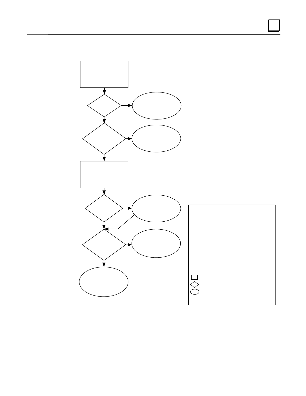
States of the Series 90-30 CMM321 Ethernet Interface
1
The Ethernet Interface is initialized by
- Powering-up the PLC
Ethernet Interf ace
Initializing
(approx. 2-10
seconds)
Diagnostics
Pass?
1
No
Yes
- S tori ng a new c onf igur ation to the P LC wi th c han ges f or t he Et her net In ter fac e
- Pressing the Restart pushbutton
- Issuing a Station Manager
- Internal System Error occurring when Interface is Operational
A
Hardware
Failu re
RESTART, LOAD
, or
MAINT
2
command
Load
Request or
Software
Corrupted?
No
Operati onal
- Full support for client and server
capability
- Uses user defined Advanced Parameters
C
Waiting for
Conf iguration from
PLC CPU
(max. 2 minutes)
Done
IP address =
0.0.0.0
No
Maintenance
Request or
Fatal System
Error?
No
F
Operational
z
/
/
∗
z
z
/
/
z
2
Ye
s
3
Yes
IP Address
Received
5
Yes
Maintenance
- Client and server capability disabled
- Uses default Advanced Parameters
- Permits changes to Advanced Parameters
Software
Load
/ ∗/
D
Waiting for
IP Address
z
4
E
Maintenance
z
/ ∗/
/
z
B
2
Software Load Caused by
- Rest ar t pushbu tton pu shed un til bot tom LED tur ns ON
- Station Manager
- Detection of corrupt software
3
Waiti ng for IP Address Caused by
- Not configuring Interface using configuration software
- Configuring Interface with IP address = 0.0.0.0
- New CPU wit h no configuration
- C PU f ailur e t o comm unica te wi th Int erfa ce
4
Continue to Maint enance or Operationa l Caused by
- IP address received from network BOOTP server
- IP address entered by
5
Ma inte nanc e Re ques t C aus ed by
- Restart pushbutton pushed until bottom two LEDs tu rn ON
- Station M anager
- Fatal System Error while in Operational State forced a restart
The LEDs are labeled from top to bottom as follows:
OK
LAN
SER
STAT
The symbols used for th e LEDs are defi ned as follows:
= OFF
= ON
z
= Slow Blink; multiple slow blinking LEDs blink in unison
= Fast Blink
= Traffic (blinks when there is traff ic on the line)
∗
The process symbols are defined as follows:
= Temporary condition; requires no intervention
= Decision point during power-up
= Interface State; normally the Interface remains
in a State unless there is user intervention
command issued
LOAD
BOOTP
command issued
MAINT
Symbols
Station Manager command
GFK-1541B Chapter 2 Installation 2-13
Page 27

2
LED Pattern Where Stopped Possible Cause Corrective Actions
❍ OK
❍
❍
❍
✫ OK
✫
✫
✫
All LEDs blink in unison.
✫
❍
❍
❍
✫
●
❍
✫
(OFF)
LAN (OFF)
FDX (OFF)
STAT (OFF)
(Slowblink)
LAN (Slowblink)
FDX (Slowblink)
STAT (Slowblink)
OK (Slowblink)
LAN (OFF)
FDX (OFF)
STAT (OFF)
OK (Slowblink)
LAN (ON/Traffic/OFF)
❍
/∗/
FDX (OFF/Slowblink)
STAT (Slowblink)
A
Hardware
Failure
B
Software
Loader
C
Waiting for
Configuration
from PLC
D
Waiting for IP
Address
Fatal Hardware Error.
Restart pushbutton until
bottom LED turns ON.
Station Manager
command issued.
Software corrupt.
Did not configure slot using
PLC Programmer.
New CPU with no
configuration.
CPU not communicating
with Ethernet Interface
(Condition can last a
maximum of 2 minutes.)
Interface’s IP address has not
been configured or has been
configured as 0.0.0.0.
LOAD
Make sure the PLC has power.
Examine PLC Fault Table for clues.*
Recheck PLC Programmer
configuration.
Power off baseplate, inspect the
Interface for loose components,
reseat the Interface, and Restart.
Try a different slot.
If the problem persists, replace the
Interface or PLC hardware.
Connect a PC Software Loader and
load new software. See Appendix C.
Cycle power or press Restart
pushbutton again for less than 5
seconds to restart the Interface and
clear the load request.
Use PLC Programmer configuration
software to configure the Interface
then store the configuration to the
PLC CPU.
Make sure Interface is in the correct
slot on the baseplate.
Power cycle the PLC.
Clear faults and Restart Interface.
Use PLC Programmer to configure
the Interface with a non-zero IP
address.
Use a BOOTP server to provide
Interface with a non-zero IP address.
OK and STAT blink in unison.
Restart pushbutton pressed
OK (Slowblink)
✫
(ON/Traffic/O FF)
LAN
/∗/
●
❍
FDX (Slowblink)
✫
STAT (ON/OFF)
●/❍
OK and SER blink in unison.
● OK
/
●
∗
●/❍
●/❍
1
FDX should be ON if Full
Duplex mode is activated;
otherwise, it should be OFF.
(ON)
/❍ LAN
* Identify the PLC fault message using the PLC Programmer, then refer to Table 8-1 in Chapter 8 for corrective actions.
(ON/Traffic/OFF)
FDX (ON/OFF)
STAT (ON/OFF)
1
E
Maintenance
F
Operational
until bottom two LEDs turn
ON.
Station Manager MAINT
command issued.
Internal System Error when
Interface was Operational
caused a restart and
entrance into Maintenance.
If the LAN LED is OFF,
the problem may be:
Network cable or
transceiver not connected to
Interface or bad transceiver.
Network cable not
terminated properly.
SQE not enabled on
transceiver.
If the STAT LED is OFF,
an exception condition has
occurred.
If you did not intend to enter
Maintenance press the Restart
pushbutton for less than 5 seconds.
This clears the Maintenance request.
Examine PLC Fault Table for clues.*
If you need to use the Station
Manager to troubleshoot a problem,
see GFK-1186, TCP/IP Ethernet
Communications for the Series 90
PLC Station Manager Manual.
Connect cable and transceiver
properly. Replace transceiver.
Terminate network cable properly.
Set SQE ON on transceiver in accord
with manufacturer’s instructions.
Examine PLC Fault Table to find out
why the STAT LED is OFF. *
2-14 TCP/IP Ethernet Communications for the Series 90™ PLC User's Manual – May 2002 GFK-1541B
Page 28

Pinging TCP/IP Ethernet Interfaces on the Network
PING (Packet InterNet Grouper) is the name of a program used on TCP/IP networks to test
reachability of destinations by sending them an ICMP echo request message and waiting for a
reply. Most nodes on TCP/IP networks, including the CMM321, implement a
PING
2
command.
You should
it verifies that the interface is operational and configured properly. Specifically, it verifies
ping,
that acceptable TCP/IP configuration information has been stored to the Interface.
each installed Ethernet Interface. When the Ethernet Interface responds to the
ping
Pinging the Interface from a UNIX® host or a PC Running TCP/IP Software
A
command can be executed from a UNIX host or PC running TCP/IP (since most TCP/IP
ping
communications software provides a
using a PC or UNIX host, the user can refer to the documentation for the
general all that is required is the IP address of the remote host as a parameter to the
For example, at the command prompt type:
ping 10.0.0.1
command) or from another Ethernet Interface.* When
ping
command, but in
ping
Determining If an IP Address Has Already Been Used
It is very important not to duplicate IP addresses.
Ethernet Interface with the same IP address as another node:
1. Disconnect your Interface from the LAN.
2. Ping the disconnected Interface’s IP address. If you get an answer to the ping, then the
chosen IP address is already in use by another node. You
assigning unique IP addresses.
To determine if you have configured your
correct this situation by
must
command.
ping
* To use another GE Fanuc Ethernet Interface, refer to the
Ethernet Communications for the Series 90 PLC Station Manager Manual.
® UNIX is a registered trademark exclusively licensed through X/Open Company LTD.
GFK-1541B Chapter 2 Installation 2-15
command in GFK-1186,
PING
TCP/IP
Page 29
2
Installing an IC693CPU364 with Embedded TCP/IP Ethernet Interface
The CPU364 with Embedded Ethernet Interface is mounted on the Series 90-30 PLC baseplate. It
is connected to an Ethernet network via a 10Base-T port or a user-provided transceiver cable and
transceiver via an AAUI port.
IC693CPU364 Series 90-30 CPU Module with Ethernet Interface
EOK
LAN
STAT
CPU364
ON
ETHERNET
RESTART
STATION
MGR
RS-232
AAUI
10BASET
PS
PORT
OFF
RESTART
PUSHBUTTON
FUSE
DEFAULT
STATION
ADDRESS
LABEL
SERIAL
NUMBER
LABEL
The Series 90-30 CPU364 has several user-accessible elements (only the Ethernet Interface
elements are discussed here.)
Three Ethernet LEDs are located at the top left of the board. The Ethernet Restart pushbutton is
located below the LEDs. The RS-232 serial port with the RJ-11 connector (similar to a modular
telephone connector) is used to connect to Station Manager and to load software updates. Below
the serial port are two ports, either one of which can be used to connect to the Ethernet network:
the 14-pin AAUI connector (Transceiver port) and the 10Base-T, RJ-45 network port.
The default station address (MAC address) label, serial number label, and replaceable AAUI port
fuse are concealed by the front cover. The front cover must be removed to access these items.
2-16 TCP/IP Ethernet Communications for the Series 90™ PLC User's Manual – May 2002 GFK-1541B
Page 30

LEDs
There are four LEDs on the CPU364: EOK, LAN, STAT, and PS PORT (on some early models
of the CPU364, the PS PORT LED is labeled “SNP”). The PS (Power Supply) PORT LED is not
Ethernet related; it indicates the presence of serial traffic through the serial port of the PLC’s
power supply. Each of the three Ethernet LEDs (EOK, LAN, and STAT) can be ON, OFF,
BLINKING slow, or BLINKING fast. They indicate the state of the Ethernet Interface, traffic on
the network port (LAN LED), and that an exception event has occurred.
The three Ethernet LEDs are briefly turned ON whenever a restart is performed in the Operational
state by pressing and releasing the Restart pushbutton (described below). This allows you to
verify that the Ethernet LEDs are operational.
Ethernet Restart Pushbutton
The Ethernet Restart pushbutton serves four functions: LED test, Restart, Restart and enter
Software Load state, and Restart and enter Maintenance state. These four functions behave
similarly in all states except for the Software Load state. While in this state, pressing the
pushbutton will cause an immediate restart into the Operational state (without performing the
LED test) if the software in the Ethernet Interface has not been corrupted or erased. If the
software has been corrupted or erased, pressing the pushbutton will cause an immediate restart
back into the Software Load state. The following text describes Restart pushbutton behavior
while not in the Software Load state.
2
Pressing the Ethernet Restart pushbutton will disrupt Ethernet communications.
LED Test:
ON. The operator should visually verify that the three LEDs go OFF and then ON at this time.
Then the Interface performs either a restart, a restart and enter Software Load state, or a restart
and enter Maintenance state, depending on the duration that you press the pushbutton.
Restart:
restart of the Ethernet Interface. When the Restart pushbutton is pressed, the three Ethernet LEDs
go out. When it is released, the three Ethernet LEDs flash ON, then power-up diagnostics run,
and the software on the Interface is restarted into the Operational state.
Any time the Ethernet Restart pushbutton is released, the three Ethernet LEDs flash
Pressing the Ethernet Restart pushbutton momentarily (less than 5 seconds) requests a
GFK-1541B Chapter 2 Installation 2-17
Page 31

2
Restart and Enter Software Load State:
bottom LED (STAT) turns ON (between 5 and 10 seconds) forces a restart and requests entrance
to the Software Load state. A reload is used to install a software update into the module and is
not part of normal operation. When the Restart pushbutton is pressed, all LEDs go out. After
approximately 5 seconds have elapsed, the STAT LED (bottom LED) comes ON, to indicate that
the Ethernet Interface will request a reload. After the Restart pushbutton is released, the three
Ethernet LEDs flash ON, then power-up diagnostics run, and the Ethernet Interface waits for the
software load with the three Ethernet LEDs blinking in unison.
Pressing and holding the Restart pushbutton until the
Notes
Reloading the Ethernet Interface requires the attachment of the PC Software
Loader to the RS-232, RJ-11 port and initiating a load with the PC Software
Loader. The PC Software Loader is a separate software utility that updates the
communications software in the Ethernet Interface. This utility is supplied with
any updates to the Ethernet Interface software. See Appendix C, “Upgrading
the Ethernet Interface Firmware”, for more information.
At any time before you initiate a load with the PC Software Loader when the
Ethernet Interface is in the Software Load State, you can restart the Ethernet
Interface by pressing the Restart pushbutton. Pressing this pushbutton will
immediately cause the board to restart. If the reload has been initiated, see
Appendix C, “Upgrading the Ethernet Interface Firmware”, for more
information.
Restart and Enter Maintenance State:
bottom two LEDs turn ON (approximately 10 seconds) forces a restart and requests entrance to
the Maintenance state. Maintenance state must be invoked to change Advanced Parameters.
While in Maintenance state, all Advanced Parameters revert to their default value. When the
Restart pushbutton is pressed, all LEDs go out. After approximately 5 seconds, the STAT LED
comes ON, then after approximately a total of 10 seconds have elapsed, the LAN LED also comes
ON, to indicate that the Ethernet Interface will request entry to the Maintenance state. After the
Restart pushbutton is released, the three Ethernet LEDs flash ON then power-up diagnostics run
and the Ethernet Interface enters the Maintenance state.
Pressing and holding the Restart pushbutton until the
Notes
In any case, any data being transferred by the Ethernet Interface at the time of
the Restart will be lost.
The Restart pushbutton is not operable during the diagnostic phase of power-up.
The Ethernet Interface is in diagnostic phase when the EOK LED is
BLINKING fast and the other Ethernet LEDs are OFF.
2-18 TCP/IP Ethernet Communications for the Series 90™ PLC User's Manual – May 2002 GFK-1541B
Page 32

Ports on the CPU364
RS-232, RJ-11 Port (Station Manager Port)
The Station Manager port uses a 6-pin, RJ-11 “phone jack” connector. This port is used to
connect a terminal or terminal emulator to access the Station Manager software on the Ethernet
Interface. It is also used to connect to the PC Software Loader in case the communications
software in the Ethernet Interface needs to be updated. An IC693CBL316 cable (or equivalent) is
needed to connect the terminal, emulator, or Software Loader to the Ethernet Interface (see
Appendix B, “Communications Ports Characteristics”). On earlier versions of the CPU364
module, this port was labeled “Port 1 RS-232.”
Ethernet Ports
There are two Ethernet ports on the CPU364. Only one port can be used at a time. The Ethernet
Interface automatically detects the Ethernet port in use; special configuration is not required.
AAUI (Transceiver) Port
The 14-pin AAUI port provides the electrical and mechanical interface to a user-provided IEEE
802.3 transceiver cable, which connects the AAUI Port to an external Ethernet-compatible
transceiver (see Appendix B, “Communications Ports Characteristics”, for the characteristics of
the AAUI Port and suggested transceivers). The external transceiver is directly connected to the
Ethernet cable.
2
Caution
Do not connect or disconnect a transceiver cable to the AAUI port while
power is applied to the PLC. This may blow the AAUI port fuse and/or
cause permanent damage to the Ethernet Interface.
10Base-T, RJ-45 Port
This 8-pin, RJ-45 port provides a direct connection to a 10Base-T (twisted pair) Ethernet network
without an external transceiver.
GFK-1541B Chapter 2 Installation 2-19
Page 33

2
CPU364 Labels
Default Station Address Label
The Default Station Address label lists the MAC address to be used by this Interface.
Serial Number Label
The Serial Number Label indicates the serial number of this Interface.
Replaceable Surface Mount Fuse
A user-replaceable fuse is provided on the DC power that is supplied by the Ethernet Interface to
the AAUI network port for use by an external transceiver. Replace only with a surface mount
2.69x2.69x6.1mm, 125V, 1A, fast-acting fuse (such as catalog number R454 001 made by
LittelFuse; http://www.littelfuse.com). You may order this fuse from GE Fanuc. The part
number is 44A725214-001.
Removing and Installing the Fuse
1.Be sure the Series 90-30 PLC baseplate power is OFF.
Remove the CPU364 module from the baseplate.
2
.
Remove the front shroud. The CPU364 is a two-board module, the fuse is located between
3
.
the AAUI port and the 10Base-T port. See Figure 3-1.
Remove the blown fuse using a pair of small, bent-nose pliers.
4
.
Insert the new fuse. Make sure the fuse is seated properly.
5
.
Replace the front shroud and re-insert the CPU364 module.
6
.
Restore power to the baseplate.
7
.
2-20 TCP/IP Ethernet Communications for the Series 90™ PLC User's Manual – May 2002 GFK-1541B
Page 34

Installing the CPU364 in the PLC
For general information about module and system installation, refer to GFK-0356,
Programmable Controller Installation Manual
.
Equipment Required to Perform the Installation Procedures
Make sure you have the items listed below before you begin.
A Series 90-30 PLC CPU baseplate with power supply. The Series 90-30 CPU364 requires
PLC power supply IC693PWR321 (Revision K or later), IC693PWR322, or IC693PWR330.
PLC programming software: Logic Developer (all versions), Control Version 2.01 or higher,
VersaPro version 1.0 or higher, or Logicmaster 90-30 version 6.01 or higher. (And a
compatible PC-compatible personal computer.)
Ethernet cables and, if using the AAUI port, an Ethernet-compatible AAUI transceiver. (See
Appendix B, “Communications Port Characteristics”, for more information.)
A serial cable for the Station Manager port on the Ethernet Interface (see Appendix B).
Optional
A terminal or IBM-compatible personal computer equipped with terminal emulation
software. Optional
Note: If your installation requires CE Mark compliance, please refer to GFK-1179,
Installation Requirements for Conformance to Standards
, for additional guidelines.
2
Series 90-30
CPU364 Installation
Use the following instructions as a guide when inserting a module into a slot in a baseplate.
These instructions assume that the power supply on the baseplate is to your left.
Warning
Do not insert or remove modules with power applied. This could cause the
PLC to Stop, damage the module, or result in personal injury.
1
Be sure the Series 90-30 PLC baseplate power is OFF.
.
Align the module with the CPU’s base slot (slot 1) and connector. Tilt the module upwards
2
.
so that the top rear hook of the module engages the slot on baseplate.
Swing the module downward until the connectors mate and the lock-lever on the bottom of
3
.
the module snaps into place engaging the baseplate notch.
Visually inspect the module to be sure that it is properly seated.
4
.
Connect
5
.
an external transceiver, connect the transceiver cable to the 14-pin AAUI port of the Ethernet
Interface. Secure the cable. The other end of the transceiver cable should be connected to an
external IEEE 802.3 compatible transceiver which is attached to the Ethernet network. SQE
must be enabled on the transceiver. (Note: The transceiver cable may be built-in to the
transceiver or removable.)
of the Ethernet ports on the Ethernet Interface to the network. If you are using
one
Caution
Do not connect or disconnect a transceiver cable to the AAUI port while
power is applied to the PLC. This may blow the AAUI port fuse and/or
cause permanent damage to the Ethernet Interface.
6
Restore power to the baseplate.
.
Use the PLC programming software or a Hand Held Programmer to make sure the PLC CPU
7
.
is in Stop mode.
GFK-1541B Chapter 2 Installation 2-21
Page 35

2
CPU364 Configuration
Before you can use the Ethernet Interface with the Series 90-30 PLC, you must configure the
Interface using the PLC programming software. The PLC programming software allows you to
specify the modules and I/O that will reside in your Series 90-30 PLC rack(s). The Hand Held
Programmer can
For the Ethernet Interface specifically, the configuration software allows you to:
Define the Status address of the Ethernet Interface.
Assign the IP address for the Ethernet Interface, and optionally the subnet mask, the gateway
address, and the name server address.
Configure the serial ports (optional).
be used to configure the Ethernet Interface.
not
Configuring the Interface Using Windows-Based Programming Software.
To configure the Ethernet Interface using Logic Developer, Control or VersaPro programming
software, do the following:
1
Control and VersaPro, from the Browser, double-click Hardware Configuration icon.
.In
The Local Rack Window will appear. In Logic Developer, expand the hardware
configuration and the main rack in the browser.
Control and VersaPro, click the Main tab.
2
.In
Click the CPU slot, press the right mouse button, and choose Replace Module. The Module
3
.
Catalog dialog box will appear.
In the Module Catalog dialog box, select CPU model IC693CPU364, then click the OK
4
.
button. Follow the instructions on the screen until the Parameters dialog box appears.
The Parameters dialog box will allow you to edit the module’s parameters. To edit a
5
.
parameter value, click the desired tab, then click in the appropriate Values field. The
Settings, Scan, and Memory tabs contain parameters that pertain directly to CPU operation.
Refer to Online Help for more information.
The Ethernet and RS-232 tabs contain parameters directly related to the embedded Ethernet
6
.
Interface’s functionality. Some fields in the Ethernet tab must be filled in. The default
settings for the RS-232 tabs can be used. Refer to the topic “Configuration Parameters” that
follows for information on these fields. We recommend leaving the serial port parameters at
default settings.
If you want to view the power consumption of this module, click the Power Consumption tab.
7
.
After you have configured all of the module’s applicable parameters, click the OK button.
The module will now appear in the selected slot.
Store the configuration to the PLC so these settings can take effect.
8
.
For more information, refer to Online Help in the PLC programming software.
2-22 TCP/IP Ethernet Communications for the Series 90™ PLC User's Manual – May 2002 GFK-1541B
Page 36

Configuring the Interface Using the Logicmaster 90-30 Configuration Software
To configure the Ethernet Interface, access the I/O Configuration rack screen in the Logicmaster
90-30 Configuration Package, and do the following:
1
Move the cursor to the CPU slot (slot1) and press Zoom (F10) to access the CPU
.
configuration screen.
If the current CPU is the CPU364, continue to step 3. Otherwise, press CPU (F1) to access
2
.
the CPU selection menu. Use the arrow keys to highlight the CPU364 (IC693CPU364),
press Enter to select it, and then press Y to replace the module.
The initial configuration screen contains the actual CPU configuration parameters. Press
3
.
Page Down to access the configuration screens for the Ethernet Interface (Ethernet
parameters and RS-232 serial port parameters).
4
Configure the Ethernet parameters. Refer to the topic “Configuration Parameters” that
.
follows for more information on these fields.
Optionally, after you have assigned the Ethernet parameters, press Page Down to display the
5
.
serial port parameters. You can then change the default settings of the serial ports (optional).
Refer to the topic “Configuration Parameters” that follows for more information on these
fields. We recommend leaving the serial port parameters at default settings.
2
After you have completed the configuration, press the Escape key to return to the rack
6
.
display. Press Escape again to save the configuration to disk.
Store the configuration to the PLC so these settings can take effect.
7
.
Refer to GFK-0466,
Manual
software.
for more information on configuring the Ethernet Interface using Logicmaster 90-30
Logicmaster 90 Series 90-30/20/Micro Programming Software User’s
CPU364 Configuration Parameters
Ethernet Parameters
Configuration Mode:
Adapter Name:
is listed in Chapter 6, “Network Administration Support”. The Adapter Name is associated with
the IP address used in Ethernet Global Data. If supported in the PLC programming software,
view all adapter names in Hardware Configuration by going to the Edit menu, choosing Rack
Operations, and selecting Name Resolution. Adapter names are listed in the Adapter Names tab.
Status Address:
bits (16 bits) and the Channel Status bits (64 bits). The Channel Status bits are always located
immediately following the LAN Interface Status bits. The Status address can be assigned to %I,
%Q, %R, %AI or %AQ memory. The default value is the next available %I address.
This is fixed as TCP/IP.
A symbolic name representation of the associated IP address. The character set
The Status Reference Type is the location of the LAN Interface Status (LIS)
Note
Do not use the 80-bits assigned to the LIS bits and Channel Status bits for other
purposes or your data will be overwritten.
GFK-1541B Chapter 2 Installation 2-23
Page 37

2
Status Length:
automatically set to either 80 bits (for %I and %Q Status address locations) or 5 words (for %R,
%AI, and %AQ Status address locations).
IP Address, Subnet Mask, Gateway IP Address, and Name Server IP Address:
should be assigned by the person in charge of your network (the network administrator). TCP/IP
network administrators are familiar with these parameters. It is important that these parameters
are correct; otherwise, the Ethernet Interface may be unable to communicate on the network
and/or network operation may be corrupted. It is especially important that each node on the
network is assigned a
However, if you have no network administrator and are using a simple
gateways, you can use the following range of values for the assignment of local IP addresses:
10.0.0.1 First PLC
10.0.0.2 Second PLC
10.0.0.3 Third PLC
..
..
..
10.0.0.255 PLC Programmer TCP or host
Also, in this case, set the subnet mask, gateway IP address, and name server IP address to 0.0.0.0.
This is the sum of the LIS bits and the Channel Status bits. This value is
These values
IP address.
unique
isolated network
with no
Note
If the isolated network is ever connected to another network, the IP addresses
10.0.0.1 through 10.0.0.255 must not be used and the subnet mask, gateway IP
address, and name server IP address must be assigned by the network
administrator. The IP addresses must be assigned so that they are compatible
with the connected network. Refer to Chapter 6, “Network Administration
Support”, for more information on addressing.
See also “Determining If an IP Address Has Already Been Used” in this
section.
Network Time Sync
network. Currently the choices are None/DISABLED (for no network time synchronization) and
SNTP/ENABLED (for synchronization to remote SNTP servers on the network).
AAUI Transceiver Power (Watts):
the AAUI Transceiver attached to the Ethernet module (measured in Watts). The valid range is
0.0 to 2.00. The default value is 0.0.
:
Selection of the method used to synchronize the real-time clocks over the
Allows you to account for the power consumption added by
2-24 TCP/IP Ethernet Communications for the Series 90™ PLC User's Manual – May 2002 GFK-1541B
Page 38

Serial Port Parameters
These parameters are for the RS-232, RJ-11 serial port on the CPU364 module. This port is used
for both the Station Manager connection
Software Loader settings take effect automatically when the Ethernet Interface enters the
“Software Load” state. For all other states the Station Manager settings take effect. Refer to
“Verifying Proper Power-Up of the Ethernet Interface”, for more information on states of the
Ethernet Interface.
for connecting to the Software Loader. The
and
2
Data Rate (bps):
4800, 9600‡, or 19200*.
Parity:
Type of parity to be used for the port. Choices are None‡, Even, or Odd*.
Stop Bits:
Flow Control:
None*‡. The Software selection has no effect.
Modem TT (Turnaround Delay):
entered is the number of 10 ms increments for the Turnaround delay. Choices are 0*‡-255. (e.g.
a value of 100 will provide a 1000 ms, or 1 second, Turnaround delay)
Timeout:
parameter has no effect.
* Default selection for the Software Loader Port.
‡ Default selection for the Station Manager Port.
This parameter is currently not used by the Ethernet Interface. Changing this
Data rate (bits per second) for the port. Choices are 300, 600, 1200, 2400,
Enter the number of stop bits. Choices are 1*‡ or 2.
Type of flow control to be used for the port. Choices are Hardware, Software, or
Turnaround delay time to be used for the port. The value
GFK-1541B Chapter 2 Installation 2-25
Page 39

2
Verifying Proper Power-Up of the CPU364 Ethernet Interface
After configuring the Ethernet Interface, follow the procedure below to verify that the Ethernet
Interface is operating correctly.
1. Turn power OFF to the PLC for 3–5 seconds, then turn the power back ON. This will initiate
a series of diagnostic tests.
The EOK LED will blink indicating the progress of power-up.
2. The Ethernet LEDs will have the following pattern upon successful power-up. At this time
the Ethernet Interface is fully operational and on-line.
LED Ethernet Interface Online
EOK
LAN
STAT
If the STAT LED is OFF, check the PLC Fault Table. Alternatively, use the Station
Manager LOG command as explained in GFK-1186,
for the Series 90 PLC Station Manager Manual
●
●/✲
●
(ON)
(ON/Traffic)
(ON)
TCP/IP Ethernet Communications
.
Problems During Power-up
If a problem is detected during power-up, the Ethernet Interface may not transition directly to the
Operational State. If the Interface does not transition to Operational, check the LED pattern on
the Interface and refer to the following chart and table for corrective actions.
2-26 TCP/IP Ethernet Communications for the Series 90™ PLC User's Manual – May 2002 GFK-1541B
Page 40

States of the Series 90-30 CPU364 with Embedded TCP/IP Ethernet Interface
1
The Ethernet Interface is initialized by
- Powering-up the PLC
Ethernet Interface
Initializing
(approx. 2-6 seconds)
1
- Stor in g a ne w con f ig ur at ion to th e PL C wit h change s for th e Ether net In t er fa ce
- Pressing the Restart pushbutton
- Issuing a Station Manager
- Internal System Error occurring when Interface is Operational
RESTART, LOAD,
or
MAINT
command
2
Diagnostics
Pass?
Yes
Load
Request or
Software
Corrupted?
No
z
z
/ ∗/
z
/
Operational
- Full support for client and server
capabili ty
- Uses user defined Advanced
Parameters
C
Waiting for
Conf iguration
from PLC CPU
(max. 2 seconds)
Done
IP address =
0.0.0.0
No
Mainte nance
Request or
Fatal System
Error?
No
F
Operational
Hardware
Failure
Software
Load
4
/ ∗/
/
B
Waiting for
IP Address
A
D
E
Maintenance
No
2
Yes
3
Yes
z
/ ∗/
IP Address
Received
5
Yes
z
z
Maintenance
- Client and server capability disabled
- Uses default Advanced Parameters
- Permits changes to Advanced Parameters
2
Software Load Caused by
- Rest art pu sh bu tton pushe d un ti l bot tom LE D tu rns ON
- Station Manager
- Detection of corrupt software
Waiting for IP Address Caused by
3
- Not configuring Interface using configuration software
- Configuring Interface with IP address = 0.0.0.0
- New CPU with no configuration
- CPU failure to communicate with Interface
4
Continue to Maintenance or Operational Caused by
- IP address received from network BOOTP server
- IP address entered by
Maintenance Request Caused by
5
- Restart pushbutton pushed until bottom two LEDs turn ON
- Station Manager
- Fatal System Error while in O perational State for ced a restart
The LEDs are labeled from top to bottom as follows:
EOK
LAN
STAT
The symbols used for the LEDs are defined as follows :
= OFF
= ON
z
= Slow Blink; multiple slow blinking LEDs blink in unison
= Fast Blink
∗
= Traffic (blinks when there is traffic on the line)
The process symbols are defined as follows:
= Temporary condition; requires no intervention
= Decision point during power-up
= Interface State; normally the Interface remains
in a State unless there is user intervention
command issued
LOAD
BOOTP
MAINT
Symbols
Station Manager command
command issued
GFK-1541B Chapter 2 Installation 2-27
Page 41

2
LED Pattern Where Stopped Possible Cause Corrective Actions
EOK (OFF)
❍
LAN (OFF)
❍
STAT (OFF)
❍
EOK (Slowblink)
✫
LAN (Slowblink)
✫
STAT (Slowblink)
✫
All LEDs blink in unison.
EOK (Slowblink)
✫
LAN (OFF)
❍
STAT (OFF)
❍
EOK (Slowblink)
✫
❍
LAN (ON/Traffic/OFF)
●
/✲/
STAT (Slowblink)
✫
EOK and STAT blink in unison.
EOK (Slowblink)
✫
❍
LAN (ON/Traffic/OFF)
●
/✲/
❍
STAT(ON/OFF)
●
/
EOK (ON)
●
❍
●
LAN (ON/Traffic/OFF)
/✲/
❍
STAT(ON/OFF)
●
/
A
Hardware
Failure
B
Software
Loader
C
Waiting for
Configuration
from PLC
D
Waiting for IP
Address
E
Maintenance
F
Operational
Fatal Hardware Error.
Restart pushbutton until the
bottom LED turns ON.
Station Manager LOAD
command issued.
Software corrupt.
Did not configure slot using
the PLC Programmer.
CPU not communicating
with Ethernet Interface.
(Condition can last a
maximum of 2 seconds.)
Interface’s IP address has not been
configured or has been configured
as 0.0.0.0.
Restart pushbutton until the
bottom two LEDs turn ON.
Station Manager MAINT
command issued.
Internal System Error when
Interface was Operational
caused a restart and
entrance into Maintenance.
If the LAN LED is OFF, the
problem may be:
Network cable not
connected or transceiver not
connected to Interface or
bad transceiver.
Network cable not
terminated properly.
SQE not enabled on
transceiver.
Make sure the PLC has power.
Examine PLC Fault Table for
clues.
Recheck PLC Programmer
configuration.
Power off baseplate, inspect the
Interface for loose components,
reseat the module, and Restart.
If the problem persists, replace
the PLC hardware.
Connect a PC Software Loader
and load new software. See
Appendix C.
Cycle power or press Restart
pushbutton again for less than 5
seconds to restart the Interface
and clear the load request.
Use the PLC Programmer
configuration software to
configure the Interface then store
the configuration to the PLC
CPU.
Power cycle the PLC.
Clear faults and Restart Interface.
Use the PLC Programmer to
configure the Interface with a
non-zero IP address.
Use a BOOTP server to provide
Interface with a non-zero IP
address.
If you did not intend to enter
Maintenance press the Restart
pushbutton for less than 5
seconds. This clears the
Maintenance request.
Examine PLC Fault Table for
clues.
If you need to use the Station
Manager to troubleshoot a
problem, see GFK-1186, TCP/IP
Ethernet Communications for the
Series 90 PLC Station Manager
Manual.
Connect cable and transceiver
properly. Replace transceiver.
Terminate network cable
properly.
Set SQE ON on transceiver in
accord with manufacturer’s
instructions.
Examine PLC Fault Table to find
If the STAT LED is OFF, an
exception condition has occurred.
2-28 TCP/IP Ethernet Communications for the Series 90™ PLC User's Manual – May 2002 GFK-1541B
out why the STAT LED is OFF.
Page 42

Pinging TCP/IP Ethernet Interfaces on the Network
PING (Packet InterNet Grouper) is the name of a program used on TCP/IP networks to test
reachability of destinations by sending them an ICMP echo request message and waiting for a
reply. Most nodes on TCP/IP networks, including the Series 90-30 CPU364, implement a
command.
2
PING
You should
it verifies that the interface is operational and configured properly. Specifically it verifies
ping,
that acceptable TCP/IP configuration information has been stored to the Interface.
each installed Ethernet Interface. When the Ethernet Interface responds to the
ping
Pinging the Interface from a UNIX® Host or a PC Running TCP/IP Software
A
command can be executed from a UNIX host or PC running TCP/IP (since most TCP/IP
ping
communications software provides a
using a PC or UNIX host, the user can refer to the documentation for the
general all that is required is the IP address of the remote host as a parameter to the
For example, at the command prompt type:
ping 10.0.0.1
command) or from another Ethernet Interface.* When
ping
command, but in
ping
Determining If an IP Address Has Already Been Used
It is very important not to duplicate IP addresses.
Ethernet Interface with the same IP address as another node:
1. Disconnect your Interface from the LAN.
2. Ping the disconnected Interface’s IP address. If you get an answer to the ping, then the
chosen IP address is already in use by another node. You
assigning unique IP addresses.
To determine if you have configured your
correct this situation by
must
command.
ping
* To use another GE Fanuc Ethernet Interface, refer to the
TCP/IP Ethernet Communications for the Series 90 PLC Station Manager Manual.
® UNIX is a registered trademark exclusively licensed through X/Open Company LTD.
GFK-1541B Chapter 2 Installation 2-29
command in GFK-1186,
PING
Page 43

2
Installing an IC693 CPU374 with Embedded TCP/IP Ethernet Interface
The CPU374 with Embedded Ethernet Interface is mounted on the Series 90-30 PLC baseplate. It
is connected to an Ethernet network via either or both of its auto-sensing 10Base-T/ 100Base TX
ports.
IC693CPU374 Series 90-30 CPU Module with Ethernet Interface
PORT
CPU374
ON
ETHERNET
RESTART
PS
OFF
STATION
MGR
LINK/ACT
PORT 1
100Mbps
LINK/ACT
PORT 2
100Mbps
FRAME
DEFAULT
STATION
ADDRESS
LABEL
SERIAL
NUMBER
LABEL
EOK
LAN
STAT
10/100 ETHERNET
10/100 ETHERNET
The Series 90-30 CPU374 has several user-accessible elements (only the Ethernet Interface’s
applicable elements are discussed here.)
Three Ethernet LEDs are located at the top left of the module. The Ethernet Restart pushbutton is
located below the LEDs. The RS-232 serial port with the RJ-11 connector (similar to a modular
telephone connector) is used to connect to Station Manager. Below the serial port are twoRJ-45
ports, either or both of which can be used to connect to the Ethernet network..
The default station address (MAC address) label is located on the outside of the module.
LEDs
There are eight LEDs on the CPU374. Four of these LEDs: EOK, LAN, STAT, and PS PORT
give module status information. Four LEDS are associated with the two RJ-45 ports. The PS
(Power Supply) PORT LED is not Ethernet related; it indicates the presence of serial traffic
through the serial port of the PLC’s power supply. Each of the three Ethernet LEDs (EOK, LAN,
and STAT) can be ON, OFF, BLINKING slow, or BLINKING fast. They indicate the state of the
Ethernet Interface, traffic at the Ethernet Interface (LAN LED), and that an exception event has
occurred.
2-30 TCP/IP Ethernet Communications for the Series 90™ PLC User's Manual – May 2002 GFK-1541B
Page 44

The seven Ethernet LEDs are briefly turned ON whenever a restart is performed in the
Operational state by pressing and releasing the Restart pushbutton (described below). This allows
you to verify that the Ethernet LEDs are operational.
Each RJ-45 port has two green LED indicators on it. The upper indicator, labeled LINK/ACT,
lights when the link is physically present and blinks when traffic is detected on the port. Traffic at
the port does not necessarily mean that traffic is present at the Ethernet Interface, because the
traffic can be going between the two ports of the switch. The lower indicator, labeled 100MBPS,
lights if the network connection is 100Mbps.
See “Verifying Proper Power-Up of the Ethernet Interface” for more LED information.
Ethernet Restart Pushbutton
The Ethernet Restart pushbutton serves two functions: LED test and Restart. These functions
behave similarly in all states.
Pressing the Ethernet Restart pushbutton will disrupt Ethernet communications (including any
communications to other devices attached to the embedded switch).
2
LED Test:
ON. The operator should visually verify that the LEDs go OFF and then ON at this time. Then
the Interface performs a restart.
Restart:
When the Restart pushbutton is pressed, the seven Ethernet LEDs go out then flash ON, then
power-up diagnostics run, and the software on the Interface is restarted into the Operational state.
Any time the Ethernet Restart pushbutton is pressed, the seven Ethernet LEDs flash
Pressing the Ethernet Restart pushbutton requests a restart of the Ethernet Interface.
Ports on the CPU374
RS-232, RJ-11 Port (Station Manager Port)
The RS-232, 6-pin, RJ-11 “phone jack” port is used to connect a terminal or terminal emulator to
access the Station Manager software on the Ethernet Interface. A cable is needed to connect the
terminal, emulator, or Software Loader to the Ethernet Interface (see Appendix B,
“Communications Ports Characteristics”).
Ethernet Ports
There are two RJ-45 Ethernet ports on the Ethernet Interface. Either or both of these ports may be
attached to other Ethernet devices. Each port automatically senses the data rate (10Mbps or
100Mbps), duplex (half duplex or full duplex), and cabling arrangement (straight through or
crossover) of the attached link.
Caution
The two ports on the Ethernet Interface must not be connected, directly or
indirectly to the same device. The hub or switch connections in an Ethernet
network must form a tree, otherwise duplication of packets may result.
CPU374 Labels
Default Station Address Label
The Default Station Address label lists the MAC address to be used by this Interface.
Serial Number Label
The Serial Number Label indicates the serial number of this Interface.
GFK-1541B Chapter 2 Installation 2-31
Page 45

2
Installing the CPU374 in the PLC
For general information about module and system installation, refer to GFK-0356,
Programmable Controller Installation Manual
.
Series 90-30
Equipment Required to Perform the Installation Procedures
Make sure you have the items listed below before you begin.
A Series 90-30 PLC CPU baseplate with power supply. The Series 90-30 CPU374 requires
PLC power supply IC693PWR321, (Revision K or later), IC693PWR322, or IC693PWR330.
A high capacity Power Supply is recommended as the 374 uses about 60% of a standard
Power Supply’s capacity.
PLC programming software: Logic Developer Version 2.60 or higher, Control Version 2.01
or higher, or VersaPro version 2.03 or higher. (And a compatible PC-compatible personal
computer.)
Ethernet cables.
A serial cable for the Station Manager port on the Ethernet Interface (see Appendix B).
Optional
A terminal or IBM-compatible personal computer equipped with terminal emulation
software. Optional
Note
If your installation requires CE Mark compliance, please refer to GFK-1179,
Installation Requirements for Conformance to Standards
programming software, for additional guidelines.
, shipped with the PLC
CPU374 Installation
Use the following instructions as a guide when inserting a module into a slot in a baseplate.
These instructions assume that the power supply on the baseplate is to your left.
Warning
Do not insert or remove modules with power applied. This could cause the
PLC to Stop, damage the module, or result in personal injury.
Be sure the Series 90-30 PLC baseplate power is OFF.
1
.
Align the module with the CPU’s base slot (slot 1) and connector. Tilt the module upwards
2
.
so that the top rear hook of the module engages the slot on baseplate.
Swing the module downward until the connectors mate and the lock-lever on the bottom of
3
.
the module snaps into place engaging the baseplate notch.
Visually inspect the module to be sure that it is properly seated.
4
.
Connect one or both of the Ethernet ports on the Ethernet Interface to the network.
5
.
Restore power to the baseplate.
6
.
Use the PLC programming software or a Hand Held Programmer to make sure the PLC CPU
7
.
is in Stop mode.
2-32 TCP/IP Ethernet Communications for the Series 90™ PLC User's Manual – May 2002 GFK-1541B
Page 46

CPU374 Configuration
Before you can use the Ethernet Interface with the Series 90-30 PLC, you must configure the
Interface using the PLC programming software. The PLC programming software allows you to
specify the modules and I/O that will reside in your Series 90-30 PLC rack(s). The Hand Held
Programmer can
For the Ethernet Interface specifically, the configuration software allows you to:
Define the Status address of the Ethernet Interface.
Assign the IP address for the Ethernet Interface, and optionally the subnet mask, the gateway
address, and the name server address.
Configure the serial ports (optional).
be used to configure the Ethernet Interface.
not
Configuring the Interface Using Windows-Based Programming Software.
To configure the Ethernet Interface using Logic Developer, Control, or VersaPro programming
software, do the following:
1
Control and VersaPro, from the Browser, double-click Hardware Configuration icon.
.In
The Local Rack Window will appear. In Logic Developer, expand the hardware
configuration and the main rack in the browser.
2
Control and VersaPro, click the Main tab.
2
.In
Click the CPU slot, press the right mouse button, and choose Replace Module. The Module
3
.
Catalog dialog box will appear.
In the Module Catalog dialog box, select CPU model IC693CPU374, then click the OK
4
.
button. Follow the instructions on the screen until the Parameters dialog box appears.
The Parameters dialog box will allow you to edit the module’s parameters. To edit a
5
.
parameter value, click the desired tab, then click in the appropriate Values field. The
Settings, Scan, and Memory tabs contain parameters that pertain directly to CPU operation.
Refer to Online Help for more information.
The Ethernet and RS-232 tabs contain parameters directly related to the embedded Ethernet
6
.
Interface’s functionality. Some fields in the Ethernet tab must be filled in. The default
settings for the RS-232 tabs can be used. Refer to the topic “Configuration Parameters” that
follows for information on these fields. We recommend leaving the serial port parameters at
default settings.
If you want to view the power consumption of this module, click the Power Consumption tab.
7
.
After you have configured all of the module’s applicable parameters, click the OK button.
The module will now appear in the selected slot.
Store the configuration to the PLC so these settings can take effect.
8
.
For more information, refer to Online Help in the PLC programming software.
GFK-1541B Chapter 2 Installation 2-33
Page 47

2
CPU374 Configuration Parameters
Ethernet Parameters
Configuration Mode:
Adapter Name:
changed.
Status Address:
bits (16 bits) and the Channel Status bits (64 bits). The Channel Status bits are always located
immediately following the LAN Interface Status bits. The Status address can be assigned to %I,
%Q, %R, %AI or %AQ memory. The default value is the next available %I address.
This is fixed as TCP/IP.
This field is set to 0.1 (the rack and slot of the Ethernet Interface) and cannot be
The Status Reference Type is the location of the LAN Interface Status (LIS)
Note
Do not use the 80-bits assigned to the LIS bits and Channel Status bits for other
purposes or your data will be overwritten.
Status Length:
automatically set to either 80 bits (for %I and %Q Status address locations) or 5 words (for %R,
%AI, and %AQ Status address locations).
IP Address, Subnet Mask, and Gateway IP Address :
person in charge of your network (the network administrator). TCP/IP network administrators are
familiar with these parameters. It is important that these parameters are correct; otherwise, the
Ethernet Interface may be unable to communicate on the network and/or network operation may
be corrupted. It is especially important that each node on the network is assigned a
address.
This is the sum of the LIS bits and the Channel Status bits. This value is
These values should be assigned by the
unique
IP
However, if you have no network administrator and are using a simple
gateways, you can use the following range of values for the assignment of local IP addresses:
10.0.0.1 First PLC
10.0.0.2 Second PLC
10.0.0.3 Third PLC
..
..
..
10.0.0.255 PLC Programmer TCP or host
isolated network
with no
2-34 TCP/IP Ethernet Communications for the Series 90™ PLC User's Manual – May 2002 GFK-1541B
Page 48

Also, in this case, set the subnet mask, and gateway IP address to 0.0.0.0.
Note
If the isolated network is ever connected to another network, the IP addresses
10.0.0.1 through 10.0.0.255 must not be used and the subnet mask,and
gateway IP address must be assigned by the network administrator. The IP
addresses must be assigned so that they are compatible with the connected
network. Refer to Chapter 6, “Network Administration Support”, for more
information on addressing.
See also “Determining If an IP Address Has Already Been Used”.
2
Network Time Sync
network. Currently the choices are None/DISABLED (for no network time synchronization) and
SNTP/ENABLED (for synchronization to remote SNTP servers on the network).
:
Selection of the method used to synchronize the real-time clocks over the
Serial Port Parameters
These parameters are for the RS-232, RJ-11 serial port on the Ethernet Interface. This port is
used for the Station Manager connection.
Data Rate (bps):
or 19200.
Parity:
Type of parity to be used for the port. Choices are None‡, Even, or Odd*.
Flow Control:
None. The Software selection has no effect.
Data rate (bits per second) for the port. Choices are 1200, 2400, 4800, 9600,
Type of flow control to be used for the port. Choices are Hardware, Software, or
GFK-1541B Chapter 2 Installation 2-35
Page 49

2
Advanced User Parameters
Advanced User Parameters may be set for the Ethernet Interface by creating an AUP file and
putting it into the folder for the PLC application.
The AUP file is a text file, created by any convenient text editor. The file name must be
"AUP_0_1.APF". The first line of the file must consist only of the text: "AUP_0_1". Subsequent
lines in the file many contain assignments for Advanced User Parameter values using the syntax:
<parameter name>=value
There should be no space between the parameter name and the equal or between the equal and the
value. Parameter names are the same as described in GFK-1186,
Communications for the Series 90 PLC, Station Manager Manual
PARM command.
Parameter values are converted to lowercase unless enclosed in a pair of double quotes; the
parameter value data depends on the parameter. Numeric parameters are entered in decimal or
hexadecimal format; hexadecimal values must be terminated with an 'h' or 'H' character. IP
address parameters must be entered in standard dotted decimal format. Character string values are
case-sensitive; as with Station Manager commands uppercase parameter values must be enclosed
within a pair of double quotes.
TCP/IP Ethernet
, in the description of the
The semicolon character delimits comments; all characters in the line following a semicolon are
ignored. An entire line may be ignored by inserting a semicolon as the first character in the line. A
blank line is also ignored.
Caution
The IEEE 802.3 standard strongly discourages the manal configuration of
duplex mode for a port (as would be possible using Advanced User
Parameters.) Before manually configuring duplex mode for a port using
AUP, be sure that you know the characteristics of the link partner and are
aware of the consequences of your selection. In the words of the IEEE
standard: "Connecting incompatible DTE/MAU combinations such as full
duplex mode DTE to a half duplex MAU, or a full-duplex station (DTE or
MAU) to a repeater or other half duplex network, can lead to severe
network performance degradation, increased collisions, ate collisions, CRC
errors, and undetected data corruption."
Note
If speed and duplex mode of a port is forced using AUP, the switch will no
longer perform automatic cable detection. This means that if you have the
switch port connected to a switch or hub port you must use a crossover
cable. If you have the switch port connected to the uplink port on a switch
or hub or if you have the switch port connected to another Ethernet device
you must use a normal cable.
An example AUP file for the CPU374 to set the IP "Time to Live (TTL)" parameter to the value 5
is shown below. This text would appear in a file named "AUP_0_1.AUP" in the directory of the
folder for the PLC:
AUP_0_1
;
; Set IP TTL to 5 ;
ittl=5
2-36 TCP/IP Ethernet Communications for the Series 90™ PLC User's Manual – May 2002 GFK-1541B
Page 50

Verifying Proper Power-Up of the CPU374 Ethernet Interface
After configuring the Interface, follow the procedure below to verify that the Ethernet Interface is
operating correctly.
1. Turn power OFF to the PLC for 3–5 seconds, then turn the power back ON. This will initiate
a series of diagnostic tests.
The EOK LED will blink indicating the progress of power-up.
2. The Ethernet LEDs will have the following pattern upon successful power-up. At this time
the Ethernet Interface is fully operational and on-line.
LED Ethernet Interface Online
EOK
LAN
STAT
If STAT LED is OFF, check the PLC Fault Table. Alternatively, use the Station
Manager LOG command as explained in GFK-1186,
for the Series 90 PLC Station Manager Manual
●
●/✲
●
(ON)
(ON/Traffic)
(ON)
TCP/IP Ethernet Communications
.
2
Problems During Power-up
If a problem is detected during power-up, the Ethernet Interface may not transition directly to the
Operational State. If the Interface does not transition to Operational, check the LED pattern on
the Interface and refer to the following chart and table for corrective action.
GFK-1541B Chapter 2 Installation 2-37
Page 51

2
States of the Series 90-30 CPU374 with Embedded TCP/IP Ethernet Interface
1
The Ethernet Interface is initialized by
Powering up the PLC
Ethernet Interface
Initializing
(approx. 2-6
seconds)
Diagnostics
Pass?
Load
Request or
Software
Corrupted?
Waiting for
Configuration from
PLC CPU
(max. 2 seconds)
IP address
= 0.0.0.0
z
/∗/
z
z
Operational
Operational
/
Full support for client and server capanility
Uses user-defined Advanced Parameters
1
Yes
Yes
No
C
Done
Yes
No
E
No
2
3
/∗/
z
IP Address
Received
Storing a new configuration to the PLC with changes for the Ethernet Interface
Pressing the Restart pushbutton
Issuing a Station Manager RESTART command
Internal System Error occurring when Interface is operational
A
Hardware
Failure
2
Software Load caused by
Pressing the Restart pushbutton
Detection of corrupt software
3
Waiting for IP Address caused by
Not configuring Interface using configuration software
Configuring Interface with IP Address = 0.0.0.0
New CPU with no configuration
CPU failure to communication with Interface
4
Continue to Operational State caused by
IP Address received over network
Symbols
The LEDs are labeled from top to bottom as follows:
EOK
LAN
STAT
The symbols use for the LEDS i the chart are:
OFF
ON
z
Slow Blink; multiple slow blinking LEDS blink in
unison
Fast Blink
Traffic (blinks when there is traffic on the line.
∗
The process symbols use in this chart are:
Temporary condition; requires no intervention
Decision point during powerup
Interface State; normally the Interface remains in a
state unless there is user intervention.
4
B
Software
Load
D
Waiting for
IP Address
2-38 TCP/IP Ethernet Communications for the Series 90™ PLC User's Manual – May 2002 GFK-1541B
Page 52

LED Pattern Where Stopped Possible Cause Corrective Actions
EOK (OFF)
❍
LAN (OFF)
❍
STAT (OFF)
❍
EOK (Slowblink)
✫
LAN (Slowblink)
✫
STAT (Slowblink)
✫
All LEDs blink in unison.
EOK (Slowblink)
✫
LAN (OFF)
❍
STAT (OFF)
❍
EOK (Slowblink)
✫
❍
LAN (ON/Traffic/OFF)
●
/✲/
STAT (Slowblink)
✫
EOK and STAT blink in unison.
EOK (ON)
●
❍
●
LAN (ON/Traffic/OFF)
/✲/
❍
STAT(ON/OFF)
●
/
A
Hardware
Failure
B
Software
Loader
C
Waiting for
Configuration
from PLC
D
Waiting for IP
Address
E
Operational
Fatal Hardware Error.
Software corrupt.
Did not configure slot using the
PLC Programmer.
CPU not communicating with
Ethernet Interface.
(Condition can last a maximum of
2 seconds.)
Interface’s IP address has not been
configured or has been configured
as 0.0.0.0.
If the LAN LED is OFF,
the problem may be
network cable not
connected
If the STAT LED is OFF, an
exception condition has
occurred.
Make sure the PLC has power.
Examine PLC Fault Table for clues.
Recheck PLC Programmer
configuration.
Power off baseplate, inspect the
Interface for loose components,
reseat the module, and Restart.
If the problem persists, replace the
PLC hardware.
Connect a PC Software Loader and load
new software. See Appendix C.
Use the PLC Programmer
configuration software to configure
the Interface then store the
configuration to the PLC CPU.
Power cycle the PLC.
Clear faults and Restart Interface.
Use the PLC Programmer to
configure the Interface with a nonzero IP address.
Assign IP address over network
Connect cable.
Examine PLC Fault Table to find out
why the STAT LED is OFF.
2
GFK-1541B Chapter 2 Installation 2-39
Page 53

2
Pinging TCP/IP Ethernet Interfaces on the Network
PING (Packet InterNet Grouper) is the name of a program used on TCP/IP networks to test
reachability of destinations by sending them an ICMP echo request message and waiting for a
reply. Most nodes on TCP/IP networks, including the Series 90-30 CPU374, implement a
command.
PING
You should
it verifies that the interface is operational and configured properly. Specifically it verifies
ping,
that acceptable TCP/IP configuration information has been stored to the Interface.
each installed Ethernet Interface. When the Ethernet Interface responds to the
ping
Pinging the Interface from a UNIX® Host or a PC Running TCP/IP Software
A
command can be executed from a UNIX host or PC running TCP/IP (since most TCP/IP
ping
communications software provides a
using a PC or UNIX host, the user can refer to the documentation for the
general all that is required is the IP address of the remote host as a parameter to the
For example, at the command prompt type:
ping 10.0.0.1
command) or from another Ethernet Interface.* When
ping
command, but in
ping
Determining If an IP Address Has Already Been Used
It is very important not to duplicate IP addresses.
Ethernet Interface with the same IP address as another node:
1. Disconnect your Interface from the LAN.
3. Ping the disconnected Interface’s IP address. If you get an answer to the ping, then the
chosen IP address is already in use by another node. You
assigning unique IP addresses.
To determine if you have configured your
correct this situation by
must
command.
ping
* To use another GE Fanuc Ethernet Interface, refer to the
TCP/IP Ethernet Communications for the Series 90 PLC Station Manager Manual.
® UNIX is a registered trademark exclusively licensed through X/Open Company LTD.
2-40 TCP/IP Ethernet Communications for the Series 90™ PLC User's Manual – May 2002 GFK-1541B
command in GFK-1186,
PING
Page 54

Installing the IC697CMM742 Ethernet Interface
The IC697CMM742 Ethernet Interface is mounted in a Series 90-70 PLC rack. It is connected to
an Ethernet network via a 10Base-T port, a 10Base2 port, or a user-provided transceiver cable and
transceiver via an AUI port.
IC697CMM742 Ethernet Interface
2
LEDS
RESTART
PUSHBUTTON
STATION MGR (RS-232)
SERIAL PORT
SERVICE OPT ION
CONNECTOR
OFTWARE LOAD (RS-485)
SERIAL PORT
10BaseT NETWORK
PORT
AUI NETWORK PORT
10Base2 NETWORK
PORT
ETHERNET
INTERFACE
MODULE OK
LAN ONLINE
SERIAL ACTIVE
STATUS
RESTART
STATION
MGR
SERVICE
OPTION
S/W
LOAD
BASE
AUI
BASE
RS
232
RS
485
10
T
OR
OR
10
2
S
E
R
I
A
L
C
O
N
N
E
C
T
I
O
N
S
E
T
H
E
R
N
E
T
C
O
N
N
E
C
T
I
O
N
DEFAULT STATION ADDRESS
LABEL
DISABLE ONBOARD
10Base2 PORT JUMPER
JP7
FU3
REPLACEABLE FUSE
SERIAL
NUMBER
LABEL
a45598
The CMM742 has several user-accessible elements.
Four LEDs are located at the top of the board. The Restart pushbutton is located immediately
below the LEDs. The RS-232 serial port with the RJ-11 connector (similar to a modular
telephone connector) is the Station Manager port. The RS-485 serial port with the 15-pin “D”
connector located immediately below the Station Manager port is the module’s Software Loader
port. Below these there are three ports, any one of which can be used to connect to the Ethernet
network: the 10Base-T, RJ-45 port, the AUI port, and the 10Base2, BNC port.
LEDs
There are four LEDs on the Ethernet Interface: MODULE OK, LAN ONLINE, SERIAL
ACTIVE, and STATUS. Each of these LEDs can be ON, OFF, BLINKING slow, or BLINKING
fast. They indicate the state of the Interface, traffic on the network port (LAN ONLINE LED),
and that an exception event has occurred.
GFK-1541B Chapter 2 Installation 2-41
Page 55

2
All LEDs are briefly turned ON whenever a restart is performed in the Operational state by
pressing and releasing the Restart pushbutton (described below). This allows you to verify that all
LEDs are operational.
See “Verifying Proper Power-Up of the Ethernet Interface” for more LED information.
Ethernet Restart Pushbutton
The Restart pushbutton serves four functions: LED test, Restart, Restart and enter Software Load
state, and Restart and enter Maintenance state. These four functions behave similarly in all states
except for the Software Load state. While in this state, pressing the pushbutton will cause an
immediate restart into the Operational state (without performing the LED test) if the software in
the Ethernet Interface has not been corrupted or erased. If the software has been corrupted or
erased, pressing the pushbutton will cause an immediate restart back into the Software Load state.
The following text describes Restart pushbutton behavior while not in the Software Load state.
Pressing the Restart pushbutton will disrupt Ethernet communications.
LED Test:
visually verify that all the LEDs go OFF and then ON at this time. Then the Interface performs
either a restart, a restart and enter Software Load state, or a restart and enter Maintenance state,
depending on the duration that you press the pushbutton.
Restart:
the Ethernet Interface. When the Restart pushbutton is pressed, all LEDs go out. When it is
released, all LEDs flash ON, then power-up diagnostics run, and the software on the Interface is
restarted into the Operational state.
Restart and Enter Software Load State:
bottom LED (STATUS) turns ON (between 5 and 10 seconds) forces a restart and requests
entrance to the Software Load state. A reload is used to install a software update into the module
and is not part of normal operation. When the Restart pushbutton is pressed, all LEDs go out.
After approximately 5 seconds have elapsed, the STATUS LED (bottom LED) comes ON, to
indicate that the Ethernet Interface will request a reload. After the Restart pushbutton is released,
all LEDs flash ON, then power-up diagnostics run, and the Ethernet Interface waits for the
software load with all LEDs blinking in unison.
Any time the Restart pushbutton is released
Pressing the Restart pushbutton momentarily (less than 5 seconds) requests a restart of
Pressing and holding the Restart pushbutton until the
the LEDs flash ON. You should
all
Note
Reloading the Ethernet Interface requires the attachment of the PC Software
Loader to the Software Loader port and initiating a load with the PC Software
Loader. The PC Software Loader is a separate software utility that updates the
communications software in the Ethernet Interface. This utility is supplied with
any updates to the Ethernet Interface software. See Appendix C, “Upgrading
the Ethernet Interface Firmware”, for more information.
Note
At any time before you initiate a load with the PC Software Loader when the
Ethernet Interface is in the Software Load state, you can restart the Ethernet
Interface by pressing the Restart pushbutton. Pressing this pushbutton will
immediately cause the board to restart. If the reload has been initiated, see
Appendix C, “Upgrading the Ethernet Interface Firmware”, for more
information.
2-42 TCP/IP Ethernet Communications for the Series 90™ PLC User's Manual – May 2002 GFK-1541B
Page 56

2
Restart and Enter Maintenance State:
bottom two LEDs turn ON (approximately 10 seconds) forces a restart and requests entrance to
the Maintenance state. Maintenance state must be invoked to change Advanced Parameters.
While in Maintenance state, all Advanced Parameters revert to their default value. When the
Restart pushbutton is pressed, all LEDs go out. After approximately 5 seconds, the STATUS
LED comes ON, then after approximately a total of 10 seconds have elapsed, the SERIAL
ACTIVE LED also comes ON, to indicate that the Ethernet Interface will request entry to the
Maintenance state. After the Restart pushbutton is released, all LEDs flash ON then power-up
diagnostics run and the Ethernet Interface enters the Maintenance state.
Pressing and holding the Restart pushbutton until the
Notes
In any case, any data being transferred by the Ethernet Interface at the time of
the Restart will be lost.
The Restart pushbutton is not operable during the diagnostic phase of power-up.
The Ethernet Interface is in diagnostic phase when the MODULE OK LED is
BLINKING fast and other LEDs are OFF.
Service Option Connector
If a problem occurs with the Ethernet Interface that requires continuous removal of power from
the rack or its removal from the rack, the on-board log event data will automatically be preserved
for 2–3 days. The service option connector allows you to attach a standard battery
(IC697ACC701) to save the log event data for longer periods.
Ports on the CMM742
There are two serial ports on the Ethernet Interface: the Station Manager port (RS-232) and the
Software Loader port (RS-485).
RS-232, RJ-11 Port (Station Manager Port)
The RS-232, 6-pin, RJ-11 “phone jack”, port is used to connect a terminal or terminal emulator to
access the Station Manager software on the Ethernet Interface. A cable is needed to connect the
terminal or emulator to the Ethernet Interface (see Appendix B, “Communications Ports
Characteristics”).
RS-485, D-Type Port (Software Loader Port)
The RS-485, 15-pin, D-type port is used to connect to the PC Software Loader in case the
communications software in the Ethernet Interface needs to be updated. The characteristics of
this port are given in Appendix B, “Communications Ports Characteristics”.
GFK-1541B Chapter 2 Installation 2-43
Page 57

2
Ethernet Ports
There are three Ethernet ports on the Ethernet Interface. Only one Ethernet port may be used at a
time. The Ethernet Interface automatically detects the Ethernet port in use; special configuration
is not required. (See also the topic “Disable Onboard 10Base2 Port Jumper” below.)
Caution
Do not connect or disconnect a transceiver or network cable to the AUI or
BNC ports while power is applied to the PLC. This may blow the port fuse
and/or cause permanent damage to the Ethernet Interface.
10BaseT Port
This 8-pin, RJ-45 port provides a direct connection to a 10Base-T (twisted pair) Ethernet network
without an external transceiver.
AUI Port
This 15-pin, D-type AUI port with slide-lock provides the electrical and mechanical interface to
the user-provided IEEE 802.3 transceiver cable, which connects the AUI Port to an external
Ethernet compatible transceiver (see Appendix B, “Communications Ports Characteristics”, for
the characteristics of the AUI port). The external transceiver is directly connected to the Ethernet
cable.
10Base2, BNC Port
This BNC port provides a direct connection to a 10Base2 (thin wire) Ethernet network without an
external transceiver.
CMM742 Labels
Default Station Address Label
The Default Station Address label lists the MAC address to be used by this Interface.
Disable Onboard 10Base2 Port Jumper
This jumper (“JP7”) must be in place to ensure proper network operation only when using an
external AUI transceiver connected to the AUI port that is externally powered. This jumper is
normally not installed.
Replaceable +12VDC Fuse
A user-replaceable fuse (FU3) is provided on the +12VDC power that is supplied by the Ethernet
Interface to the AUI network port for use by an external transceiver. Replace only with a 5 x
20mm, 250V, 1 A, fast-acting fuse.
2-44 TCP/IP Ethernet Communications for the Series 90™ PLC User's Manual – May 2002 GFK-1541B
Page 58

Installing the CMM742 in the PLC
2
For general information about module and system installation, refer to GFK-0262,
Programmable Controller Installation Manual
.
Equipment Required to Perform the Installation Procedures
Make sure you have the items listed below before you begin.
Series 90-70 PLC rack.
Series 90-70 power supply.
To use the AUI port, the power supply must be one of the following types, which
provide +12 Vdc for an external transceiver on the AUI port: IC697PWR711,
IC697PWR724, or IC697PWR748.
If the AUI port will not be used, +5 Vdc is all that is required. Under these conditions,
power supply IC697PWR710 is sufficient.
A Series 90-70 CPU.
PLC programming software: Logicmaster 90-70 version 6.02 or higher or Control version
1.0 or higher (runs on a personal computer).
Ethernet cables and, if using the AUI port, an Ethernet-compatible AUI transceiver. (See
Appendix B, “Communications Ports Characteristics”, for more information.)
A serial cable for the Station Manager port on the Ethernet Interface (see Appendix B).
Optional
A terminal or IBM-compatible personal computer equipped with terminal emulation
software. Optional
A Phillips-head screwdriver.
Series 90-70
Note
If your installation requires CE Mark compliance, please refer to GFK-1179,
Installation Requirements for Conformance to Standards
programming software, for additional guidelines.
, shipped with the PLC
GFK-1541B Chapter 2 Installation 2-45
Page 59

2
CMM742 Installation
This section describes the physical mounting of the Ethernet Interface into the Series 90-70 PLC
rack. For information on the installation procedures for the rack, Series 90-70 CPU, Power
Supply, and other Series 90-70 modules, refer to GFK-0262,
Controller Installation Manual
.
Series 90-70 Programmable
Warning
Do not insert or remove modules with power applied. This could cause the
PLC to Stop, damage the module, or result in personal injury.
Be sure the Series 90-70 PLC rack power is OFF.
1
.
Slide the Ethernet Interface into the desired slot—normally the first available slot to the right
2
.
of the CPU.
Press firmly to seat the Interface, but do not force the Interface. Tighten the screws on the
top and bottom tabs.
Note
The Series 90-70 Ethernet Interface (Type 2) must be installed in the main rack;
installation in an expansion rack is not supported. The Ethernet Interface will
not operate properly if there are empty slots to the left of the slot you select.
3
Connect
.
an external transceiver, connect the transceiver cable to the AUI port on the Ethernet
Interface. The other end of the transceiver cable should be connected to an external IEEE
802.3 compatible transceiver that is attached to the Ethernet network. SQE must be enabled
on the transceiver.
of the Ethernet ports on the Ethernet Interface to the network. If you are using
one
Caution
Do not connect or disconnect a transceiver or network cable to the AUI or
BNC ports while power is applied to the PLC. This may blow the port fuse
and/or cause permanent damage to the Ethernet Interface.
Set the CPU Run/Stop switch to STOP.
4
.
2-46 TCP/IP Ethernet Communications for the Series 90™ PLC User's Manual – May 2002 GFK-1541B
Page 60

CMM742 Configuration
Before you can use the Ethernet Interface with the Series 90-70 PLC, you must configure the
Interface using the PLC programming software. The PLC configuration software allows you to
specify the modules and I/O that will reside in your Series 90-70 PLC rack(s).
For the Ethernet Interface specifically, the configuration software allows you to:
Define the Status address of the Ethernet Interface.
Assign the IP address for the Ethernet Interface, and optionally the subnet mask, the gateway
address, and the name server address.
Configure the serial ports (optional).
Configuring the Interface Using Windows-Based Programming Software
To configure the Ethernet Interface using Logic Developer, Control, or VersaPro programming
software, do the following:
Control and VersaPro, from the Browser, double-click the 90-70 Rack System–Local
1
.In
Rack icon. The Local Rack Window will appear. In Logic Developer, expand the hardware
configuration and the desired rack in the browser.
2
Control and VersaPro, click the tab corresponding to the desired rack.
2
.In
3
Click the desired slot, press the right mouse button, and choose Add Module from the menu.
.
(If the slot already contains a module, choose Replace Module.) The Module Catalog dialog
box will appear.
In the Module Catalog dialog box, click the Communications tab, select IC697CMM742
4
.
Ethernet Controller Type 2, and then click the OK button. The Parameters dialog box then
will appear.
This dialog box will allow you to edit the module’s Ethernet parameters. To edit a parameter
5
.
value, click in the appropriate Values field.
Optionally, after you have completed the Settings tab, you can configure parameters for the
6
.
Station Manager and Software Load ports by clicking the appropriate tab. The default
settings for the serial ports can then be changed (optional). Refer to the topic “Configuration
Parameters” that follows for information on these fields. We recommend leaving the serial
port parameters at default settings.
If you want to view the power consumption of this module, click the Power Consumption tab.
7
.
After you have configured all of the module’s applicable parameters, click the OK button.
The module will now appear in the selected slot.
Store the configuration to the PLC so these settings can take effect.
8
.
For more information, refer to Online Help in the PLC programming software.
GFK-1541B Chapter 2 Installation 2-47
Page 61

2
Configuring the Interface Using Logicmaster 90-70 Configuration Software
To configure the Ethernet Interface, access the I/O Configuration rack screen in the Logicmaster
90-70 Configuration Package, and do the following:
1. Move the cursor to the desired rack and slot location. The slot may be either unconfigured or
previously configured.
2. Press the Communications softkey, i.e., Comm (F6)
3. Press ethnet (F2).
4. Press “↓” (down arrow) to highlight “IC697CMM742”, then press Enter to select the
Ethernet Interface.
5. Configure the Ethernet parameters. Refer to the topic “Configuration Parameters” that
follows for more information on these fields.
6. Optionally, after you have assigned the Ethernet parameters, press Page Down to display the
serial port parameters. You can then change the default settings of the serial ports (optional).
Refer to the topic “Configuration Parameters” that follows for more information on these
fields. We recommend leaving the serial port parameters at default settings.
7. After you have completed the configuration, press the Escape key to return to the rack
display. Press Escape again to save the configuration to disk.
8. Store the configuration to the PLC so these settings can take effect.
Refer to GFK-0263,
information on using Logicmaster 90-70 software.
Logicmaster 90-70 Programming Software User’s Manual
for more
2-48 TCP/IP Ethernet Communications for the Series 90™ PLC User's Manual – May 2002 GFK-1541B
Page 62

CMM742 Configuration Parameters
Ethernet Parameters
2
Configuration Mode:
Adapter Name:
is listed in Chapter 6, “Network Administration Support”. The Adapter Name is associated with
the IP address used in Ethernet Global Data. If supported in the PLC programming software,
view all adapter names in Hardware Configuration by going to the Edit menu, choosing Rack
Operations, and selecting Name Resolution. Adapter names are listed in the Adapter Names tab.
IP Address, Subnet Mask, Gateway IP Address, and Name Server IP Address:
should be assigned by the person in charge of your network (the network administrator). TCP/IP
network administrators are familiar with these parameters. It is important that these parameters
are correct, otherwise the Ethernet Interface may be unable to communicate on the network and/or
network operation may be corrupted. It is especially important that each node on the network is
assigned a
However, if you have no network administrator and are using a simple
gateways, you can use the following range of values for the assignment of local IP addresses:
Also, in this case, set the subnet mask, gateway IP address, and name server IP address to 0.0.0.0.
unique
10.0.0.1 First PLC
10.0.0.2 Second PLC
10.0.0.3 Third PLC
..
10.0.0.255 PLC Programmer TCP or host
This is fixed as TCP/IP.
A symbolic name representation of the associated IP Address. The character set
These values
IP address.
isolated network
.
with no
Note
If the isolated network is ever connected to another network, the IP addresses
10.0.0.1 through 10.0.0.255 must not be used and the subnet mask, gateway
IP address, and name server address must be assigned by the network
administrator. The IP addresses must be assigned so that they are compatible
with the connected network. Refer to Chapter 6, “Network Administration
Support”, for more information on addressing.
See also “Determining If an IP Address Has Already Been Used”.
Status Address:
bits (16 bits) and the Channel Status bits (64 bits). The Channel Status bits are always located
immediately following the LAN Interface Status bits. The Status address can be assigned to %I,
%Q, %R, %AI, or %AQ memory. The default value is the next available %I address.
The Status Reference Type is the location of the LAN Interface Status (LIS)
Note
Do not use the 80 bits assigned to the LIS bits and Channel Status bits for other
purposes or your data will be overwritten.
GFK-1541B Chapter 2 Installation 2-49
Page 63

2
Status Length:
automatically set to either 80 bits (for %I and %Q Status address locations) or 5 words (for %R,
%AI, and %AQ Status address locations).
Network Routing Pair #1, #2, #3:
with another network adapter within the same PLC system. Network routing pairs is an advanced
feature that should be set only by individuals who have detailed knowledge of PLC
communications.
Network Time Sync
network. Currently the choices are None (for no network time synchronization) and SNTP (for
synchronization to remote SNTP servers on the network).
This is the sum of the LIS bits and the Channel Status bits. This value is
These parameters are used to define an IP routing partnership
:
Selection of the method used to synchronize the real-time clocks over the
Serial Port Parameters
Data Rate (bps):
4800, 9600‡, or 19200*.
Parity:
Type of parity to be used for the port. Choices are None‡, Even, or Odd*.
Stop Bits:
Flow Control:
parameter has no effect.
Turnaround Delay:
are None*‡, 10 ms, 100 ms, or 500 ms.
Data rate (bits per second) for the port. Choices are 300, 600, 1200, 2400,
Enter the number of stop bits. Choices are 1*‡ or 2.
This parameter is currently not used by the Ethernet Interface. Changing this
Turnaround delay time (in milliseconds) to be used for the port. Choices
Timeout:
parameter has no effect.
* Default selection for the Software Loader Port.
‡ Default selection for the Station Manager Port.
This parameter is currently not used by the Ethernet Interface. Changing this
2-50 TCP/IP Ethernet Communications for the Series 90™ PLC User's Manual – May 2002 GFK-1541B
Page 64

Verifying Proper Power-Up of the CMM742
After configuring the Interface, follow the procedure below to verify that the Ethernet Interface is
operating correctly.
1. Turn power OFF to the PLC for 3–5 seconds, then turn the power back ON. This will
initiate a series of diagnostic tests.
The MODULE OK LED will blink indicating the progress of power-up.
2. The LEDs will have the following pattern upon successful power-up. At this time the
Ethernet Interface is fully operational and on-line.
LED Ethernet Interface Online
MODULE OK
LAN ONLINE
SERIAL ACTIVE
STATUS
If the STATUS LED is OFF, check the PLC Fault Table. Alternatively, use the Station
Manager LOG command as explained in GFK-1186,
for the Series 90 PLC Station Manager Manual
●
●/✲
❍
●
(ON)
(ON/Traffic)
(OFF)
(ON)
TCP/IP Ethernet Communications
.
2
Problems During Power-up
If a problem is detected during power-up, the Ethernet Interface may not transition directly to the
Operational state. If the Interface does not transition to Operational, check the LED pattern on the
Interface and refer to the following chart and table for corrective action.
GFK-1541B Chapter 2 Installation 2-51
Page 65

2
States of the Series 90-70 CMM742 TCP/IP Ethernet Interface
The Ethernet Interface is initialized by
1
Ethernet Interface
Initializing
(approx.10-20 seconds)
1
- Powering-up the PLC
- Storing a new configuration to the PLC with changes for the Ethernet Interface
- Pressing the Restart pushbutton
- Issuing a Station Manager
- Internal System Error occurring when Interface is Operational
RESTART, LOAD
, or
MAINT
command
Yes
No
Done
No
No
No
2
Yes
3
Yes
IP Address Received
5
Yes
Maintenance
- Client and server capability disabled
- Uses default Advanced Parameters
- Permits changes to Advanced Parameters
Diagnostics
Pass?
Load
Request or
Software
Corrupted?
z
/
z
Operational
- Full support for client and server capability
- Uses user defined Advanced Parameters
C
Waiting for
Configuration from
PLC CPU
(max. 2 minutes)
IP address =
0.0.0.0
Maintenance
Request or
Fatal System
Error?
z
/
∗
/
Operational
F
z
z
z
/ ∗/
/ ∗/
/
A
Hardware
Failure
B
Software
Load
D
Waiting for
IP Address
4
E
Maintenance
Software Load Caused by
2
- Restart pushbutton pushed until bottom LED turns ON
- Station Manager
- Detection of corrupt software
Waiting for IP Address Caused by
3
- Not configuring Interface using configuration software
- Configuring Interface with IP address = 0.0.0.0
- New CPU with no configuration
- CPU failure to communicate with Interface
Continue to Maintenance or Operational Caused by
4
- IP address received from network BOOTP server
- IP address entered by
Maintenance Request Caused by
5
- Restart pushbutton pushed until bottom two LEDs turn ON
- Station Manager
- Fatal System Error while in Operational State forced a restart
The LEDs are labeled from top to bottom as follows:
MODULE OK
LAN ONLINE
SERIAL ACTIVE
STATUS
The symbols used for the LEDs are defined as follows:
= OFF
= ON
z
= Slow Blink; multiple slow blining LEDs blink in unison
= Fast Blink
∗
= Traffic (blinks when there is traffic on the line)
The process symbols are defined as follows:
= Temporary condition; requires no intervention
= Decision point during power-up
= Interface State; normally the Interface remains
in a State unless there is user intervention
command issued
LOAD
BOOTP
command issued
MAINT
Symbols
Station Manager command
2-52 TCP/IP Ethernet Communications for the Series 90™ PLC User's Manual – May 2002 GFK-1541B
Page 66

LED Pattern Where Stopped Possible Cause Corrective Actions
pp
q
MODULE OK OFF)
❍
LAN ONLINE (OFF)
❍
SERIAL ACTIVE (OFF)
❍
STATUS (OFF)
❍
MODULE OK (Slowblink)
✫
LAN ONLINE (Slowblink)
✫
SERIAL ACT. (Slowblink)
✫
STATUS (Slowblink)
✫
All LEDs blink in unison.
MODULE OK (Slowblink)
✫
LAN ONLINE (OFF)
❍
SERIAL ACT. (OFF)
❍
Status (OFF)
❍
MODULE OK (Slowblink)
✫
❍
LAN ONL. (ON/Traffic/OFF)
●
/✲/
❍
SER. ACT (OFF/Slowblink)
STAT US (Slowblink)
✫
MODULE OK and STATUS blink in
unison.
MODULE OK (Slowblink)
✫
❍
LAN ONL. (ON/Traffic/OFF)
●
/✲/
SERIAL ACT. (Slowblink)
✫
❍
STATUS (ON/OFF)
●
/
MODULE OK and SERIAL ACTIVE
blink in unison.
MODULE OK (ON)
●
❍
LAN ONL. (ON/Traffic/OFF)
●
/✲/
SERIAL ACTIVE (OFF)
❍
❍
STATUS (ON/OFF)
●
/
A
Hardware
Failure
B
Software
Loader
C
Waiting for
Configuration
from PLC
D
Waiting for IP
Address
E
Maintenance
F
Operational
Fatal Hardware Error.
Restart pushbutton until the
bottom LED turns ON.
Station Manager LOAD
command issued.
Software corrupt.
Did not configure slot using
PLC Programmer.
New CPU with no
configuration.
CPU not communicating
with Ethernet Interface
(Condition can last a
maximum of 2 minutes.)
Interface’s IP address has not
been configured or has been
configured as 0.0.0.0.
Restart pushbutton until
bottom two LEDs turn ON.
Station Manager MAINT
command issued.
Internal System Error when
Interface was Operational
caused a restart and
entrance into Maintenance.
If the LAN ONLINE LED is
OFF, the problem may be:
Network cable not
connected or transceiver not
connected to Interface or
bad transceiver.
Network cable not
terminated properly.
SQE not enabled on
transceiver.
If the STATUS LED is OFF, an
exception condition has
occurred.
Make sure the PLC has power.
Examine PLC Fault Table for
clues.*
Recheck PLC Programmer
configuration.
Power off the PLC rack, inspect the
Interface for loose components,
reseat the Interface, and Restart.
Try a different slot.
If the problem persists, replace the
Interface or PLC hardware.
Connect a PC Software Loader and
load new software. See A
Cycle power or press Restart
pushbutton again for less than 5
seconds to restart the Interface and
clear the load request.
Use configuration software to
configure the Interface then store
the configuration to the PLC CPU.
Make sure Interface is in the correct
slot on the in the PLC rack.
Power cycle the PLC.
Clear faults and Restart Interface.
Use PLC Programmer configuration
software to configure the Interface
with a non-zero IP address.
Use a BOOTP server to provide
Interface with a non-zero IP
Address.
If you did not intend to enter
Maintenance, press the Restart
pushbutton for less than 5 seconds.
This clears the Maintenance re
Examine PLC Fault Table for
clues.*
If you need to use the Station
Manager to troubleshoot a problem,
see GFK-1186, TCP/IP Ethernet
Communications for the Series 90
PLC Station Manager Manual.
Connect cable and transceiver
properly. Replace transceiver.
Terminate network cable properly.
Set SQE ON on transceiver in
accord with manufacturer’s
instructions.
Examine PLC Fault Table to find
out why the STATUS LED is OFF.
*
2
endix C.
uest.
GFK-1541B Chapter 2 Installation 2-53
Page 67

2
Pinging TCP/IP Ethernet Interfaces on the Network
PING (Packet InterNet Grouper) is the name of a program used on TCP/IP networks to test
reachability of destinations by sending them an ICMP echo request message and waiting for a
reply. Most nodes on TCP/IP networks, including the Series 90-70 Ethernet Interface (Type 2),
implement a
PING
command.
The user should
the
verifies that acceptable TCP/IP configuration information has been stored to the Interface.
it verifies that the interface is operational and configured properly. Specifically it
ping,
each installed Ethernet Interface. When the Ethernet Interface responds to
ping
Pinging the Interface from a UNIX® Host or a PC Running TCP/IP Software
A
command can be executed from a UNIX host or PC running TCP/IP (since most TCP/IP
ping
communications software provides a
using a PC or UNIX host, the user can refer to the documentation for the
general, all that is required is the IP address of the remote host as a parameter to the
For example, at the command prompt type:
ping 10.0.0.1
command) or from another Ethernet Interface.* When
ping
command, but in
ping
Determining if an IP Address Has Already Been Used
It is very important not to duplicate IP addresses.
Ethernet Interface with the same IP address as another node:
1. Disconnect your Interface from the LAN.
2. Ping the disconnected Interface’s IP address. If you get an answer to the ping, then the
chosen IP address is already in use by another node. You
assigning unique IP addresses.
To determine if you have configured your
correct this situation by
must
command.
ping
* To use another GE Fanuc Ethernet Interface, refer to the PING command in GFK-1186,
TCP/IP Ethernet Communications for the Series 90 PLC Station Manager Manual
® UNIX is a registered trademark exclusively licensed through X/Open Company LTD.
2-54 TCP/IP Ethernet Communications for the Series 90™ PLC User's Manual – May 2002 GFK-1541B
.
Page 68

Chapter
3
Programming SRTP Channel Commands
This chapter describes how to program PLC to PLC communications over the Ethernet network
using SRTP Channel commands. To program Modbus/TCP Channel commands, see chapter 4.
The Communications Request
The COMMREQ Function Block and Command Block
SRTP Channel Commands
Status Data
Controlling Communications in the Ladder Program, which includes an example
Note
This chapter applies
SRTP/TCP/IP communications. No programming is required for SRTP server
operations.
to PLCs being used as client PLCs to
only
initiate
GFK-1541B 3-1
Page 69

3
The Communications Request
This section describes the elements of the Communications Request.
No programming of Communications Requests is required for PLCs acting as servers which are
merely targets of other systems’ requests but do not themselves initiate requests.
Structure of the Communications Request
The Communications Request is made up of the following elements:
The COMMREQ Function Block (ladder instruction)
The COMMREQ Command Block
The Channel Command
Status Data (COMMREQ Status word, LAN Interface Statusand Channel Status bits)
The logic program controlling execution of the COMMREQ Function Block
Elements of the Communications Request
The figure below illustrates the relationship of these elements:
CONTROL
LOGIC
INITIATES
COMMREQ
FUNCTION
BLOCK
COMMREQ
FUNCTION BLOCK
INPUTS
AND
OUTPUTS
FOR COMMREQ
FUNCTION
COMMAND
BLOCK
ADDRESS
COMMREQ
COMMAND BLOCK
COMMREQ
STATUS
WORD
ADDRESS
DETAILS
OF THE
CHANNEL
COMMAND
a44916c
COMMREQ
STATUS WORD
STATUS
CODES
STATUS BITS
LAN INTERFACE STATUS
AND CHANNEL STATUS
Location in PLC memory
specified when configuring
BITS
the Interface using
Configuration Software
3-2 TCP/IP Ethernet Communications for the Series 90™ PLC User's Manual – May 2002 GFK-1541B
Page 70

COMMREQ Function Block
The COMMREQ Function Block is the ladder instruction that triggers the execution of the
Channel command. In the COMMREQ Function Block, you specify the rack and slot location of
the Ethernet Interface, a task value, and the address of a location in memory that contains the
Command Block. There is also a fault output on the COMMREQ Function Block that indicates
certain programming errors.
COMMREQ Command Block
The COMMREQ Command Block is a structure that contains information about the Channel
command to be executed. The Command Block consists of two parts:
Common Area - includes the address of the COMMREQ Status word (CRS word).
Data Block Area - describes the Channel command to be executed.
When the COMMREQ function is initiated, the Command Block is transferred to the Ethernet
Interface for action.
SRTP Channel Commands
The Channel commands are a set of client PLC commands used to communicate with a server
PLC.
3
Advantages of Channel Commands
The advantage of Channel commands is their ability to establish a channel to execute multiple
periodic
can also be used to execute a single read or write.
The channel number is specified in the Command Block for the Channel command. The channel
can be monitored using the Channel Status bits and the Detailed Channel Status words.
reads or writes with a single initiation of a COMMREQ function. A Channel command
Up to 32 channels (numbered 1–32) can be established by a Series 90-70 Ethernet Interface.
Up to 16 channels (numbered 1–16) can be established by a Series 90-30 Ethernet Interface.
(If the Series 90-30 Ethernet Interface supports Modbus/TCP Channels, the 16 available
channels are shared between SRTP and Modbus/TCP.)
GFK-1541B Chapter 3 Programming Channel Commands 3-3
Page 71

3
Status Data
There are several types of status data available to the client PLC logic program.
LAN Interface Status Bits (LIS Bits):
location of this 80-bit status area is assigned using the Configuration software in the “Status
Address” field. The LIS bits contain information on the status of the Local Area Network (LAN)
and the Ethernet Interface itself.
Channel Status Bits:
area. When used for SRTP channels, these bits consist of an
each of the channels that can be established (32 channels for the Series 90-70 Ethernet Interface, 16
channels for the Series 90-30 Ethernet Interfaces). Status bits for unused channels are always set to
zero.
The Channel Status bits comprise bits 17–80 (64 bits) of the 80-bit status
COMMREQ Status Word (CRS Word):
communication request. The location of the CRS word is assigned for each COMMREQ function
in the COMMREQ Command Block.
Detailed Channel Status Words (DCS Words):
particular channel using the Retrieve Detailed Channel Status Command.
FT Output of the COMMREQ Function Block:
errors in the COMMREQ Function Block and/or Command Block and did not pass the Command
Block to the Ethernet Interface.
The LIS bits comprise bits 1–16 of the 80-bit status area. The
bit and a
error
The 16-bit CRS word will receive the initial status of the
This detailed status data is retrieved for a
This output indicates that the PLC CPU detected
data transfer
bit for
The Logic Program Controlling Execution of the COMMREQ Function Block
Care must be taken in developing the logic that controls the execution of the COMMREQ function.
The COMMREQ function must be initiated by a one-shot to prevent the COMMREQ from being
executed repeatedly each CPU scan, as this will overrun the capability of the Ethernet Interface and
possibly require a manual restart. Checking certain status bits before initiating a COMMREQ
function is also important. In particular, the LAN Interface OK bit should be used as an interlock to
prevent execution of the COMMREQ function when the Ethernet Interface is not operational.
Following initiation of a COMMREQ on a channel, no further COMMREQs should be issued to
that channel until a non-zero CRS word has been returned to the program from the Ethernet
Interface.
3-4 TCP/IP Ethernet Communications for the Series 90™ PLC User's Manual – May 2002 GFK-1541B
Page 72

Operation of the Communications Request
The figure and text below explains how a Communications Request is executed. The figure
specifically illustrates the successful operation of an Establish Read Channel command.
Domain of a channel
Client
Series 90-70
PLC CPU Backplane
Power flows to COMMREQ
in ladder program
Command Block sent to
Interface
PLC PLC
Client
Ethernet
Interface
Verify
Command Block
and set up channel
to server PLC
Domain of a TCP connection
LAN
Server
Ethernet Interface
Domain of a remote server
Backplane
Server
CPU
3
Data
COMMREQ
Status Word
Data Transfer
pulse received
Data
Data Transfer
pulse received
.
.
.
Data
Data Transfer
pulse received
Read Request
Data
Data
Return COMMREQ
Status (CRS) Word
to CPU
Pulse Data Transfer bit
Read Request
Data
Pulse Data Transfer bit
.
.
.
Read Request
Data
Pulse Data Transfer bit
Read Request
Data
Read Request
Data
Read Request
Data
1. A Communications Request begins when there is power flow to a COMMREQ function in
the client PLC. At this time, the Command Block data is sent from the PLC CPU to the
Ethernet Interface.
2. For the Establish Read Channel command, the COMMREQ Status word (CRS word) is
returned immediately if the Command Block is invalid. If the syntax is correct, then the CRS
word is returned after the first significant event: upon failure to establish a channel correctly
and in a timely manner or upon the first successful transfer of data.
Data
Data
Data
Once the channel is successfully set up to the server PLC, the Ethernet Interface performs the
periodic reads as specified in the Command Block.
GFK-1541B Chapter 3 Programming Channel Commands 3-5
Page 73

3
COMMREQ Function Block and Command Block
This section describes the programming structures common to all Communications Requests: the
COMMREQ Function Block and the Command Block.
The COMMREQ Function Block
The Communications Request is triggered when the logic program passes power to the
COMMREQ Function Block.
(Enable )
-------------
COMM
OK (Series 90-70 PLCs only)
-
REQ
(Command Block address)
(Rack/Slot Location of
the Ethernet Interface)
(Task value)
Each of the inputs and outputs are discussed in detail below. Remember that the Command Block
address points to a location in memory that has been set up as the Command Block.
Enable:
IN:
of memory (%R, %AI, or %AQ for the Series 90-30 Ethernet Interface and the Series 90-30
CPU364) (%R, %AI, %AQ, %P, or %L for the Series 90-70 Ethernet Interface (Type 2)).
SYSID:
the Ethernet Interface. For the Series 90-30 CPU364, this must always be set to 0001 to specify
rack 0, slot 1. Note that if using GE Fanuc’s VersaPro PLC software, the leading zeros in this
hexadecimal word value are not displayed on-screen; for example, 0004 will appear as 4.
Examples:
Control logic for activating the COMMREQ Function Block.
The location of the Command Block. It can be any valid address within a word-oriented area
A hexadecimal word value that gives the rack (high byte) and slot (low byte) location of
Rack Slot
-
-
-
IN
SYSID
TASK
FT
Function Faulted (logic)
-
Hex Word Value
0 4 0004H
34
29
4 2 0402H
0304H
0209H
Note
The Series 90-70 Ethernet Interface (Type 2) is supported only in the main PLC
rack (rack number 0).
3-6 TCP/IP Ethernet Communications for the Series 90™ PLC User's Manual – May 2002 GFK-1541B
Page 74

TASK:
For the Series 90-30 CPU364, this must always be set to 21 decimal (0015H). For the
Series 90-30 Ethernet Interface and the Series 90-70 Ethernet Interface (Type2), this must always
be set to zero.
Caution
Entering an incorrect TASK value may cause the Ethernet Interface to fail.
3
OK Output:
delivered the COMMREQ to the Ethernet Interface.
FT Output:
the COMMREQ fails. In this case, the other status indicators are not updated for this
COMMREQ.
(Series 90-70 PLC only) The OK output is set if the PLC CPU has successfully
The FT output is set if the PLC CPU (rather than the Ethernet Interface) detects that
The COMMREQ Command Block
When the COMMREQ function is initiated, the Command Block is sent from the PLC CPU to the
Ethernet Interface. The Command Block contains the details of a Channel command to be
performed by the Interface.
The address in CPU memory of the Command Block is specified by the IN input of the
COMMREQ Function Block. This address can be any valid address within a word-oriented area
of memory (%R, %AI, or %AQ for the Series 90-30 Ethernet Interface and the Series 90-30
CPU364) (%R, %AI, %AQ, %P, or %L for the Series 90-70 Ethernet Interface (Type 2)). The
Command Block is set up using an appropriate programming instruction (the BLOCK MOVE or
DATA_INIT (Series 90-70 PLC only) Function Blocks are recommended).
The Command Block has the following structure:
Word 1 Data Block Length (words)
Word 2 WAIT/NOWAIT Flag
Word 3 CRS Word Memory Type
Word 4 CRS Word Address Offset
Word 5
Word 6
Words 7 and up Data Block (Channel Command Details)
Reserved
Reserved
When entering information for the Command Block, refer to these definitions:
(Word 1) Data Block Length:
Command Block. The Data Block portion starts at Word 7 of the Command Block. The length is
measured from the beginning of the Data Block at Word 7, not from the beginning of the
Command Block. The correct value for each command, and the associated length of each
command, is specified in the next section.
(Word 2) WAIT/NOWAIT Flag:
Communications.
GFK-1541B Chapter 3 Programming Channel Commands 3-7
This is the length in words of the Data Block portion of the
This flag must be set to zero for TCP/IP Ethernet
Page 75

3
COMMREQ Status Word:
failure of the command. Command words 3 and 4 specify the PLC memory location of the CRS
word.
(Word 3) COMMREQ Status Word Memory Type:
CRS word. The memory types are listed in the table below:
Type Value
(Decimal)
%R 8 08H Register memory (word mode)
%AI 10 0AH Analog input memory (word mode)
%AQ 12 0
%I 16
%Q 18
%T 20
%M 22
%G 56
The Ethernet Interface updates the CRS word to show success or
This word specifies the memory type for the
70
72
74
76
86
Value
(Hex.)
CH
10H
46H
12H
48H
14H
4AH
16H
4CH
38H
56H
Description
Analog output memory (word mode)
Discrete input memory (byte mode)
Discrete input memory (bit mode)
Discrete output memory (byte mode)
Discrete output memory (bit mode)
Discrete temporary memory (byte mode)
Discrete temporary memory (bit mode)
Discrete momentary internal memory (byte mode)
Discrete momentary internal memory (bit mode)
Discrete global data table (byte mode)
Discrete global data table (bit mode)
(Word 4) COMMREQ Status Word Address Offset:
memory type selected.
you want %R1 as the location of the CRS word, you must specify a zero for the offset. The offset
for %R100 would be 99 decimal. Note, however, that this is the only zero-based field in the
Channel commands.
(Word 5):
(Word 6):
Reserved. Set to zero.
Reserved. Set to zero.
(Words 7 and up) Data Block:
The status word address offset is a zero-based number.
The Data Block defines the Channel command to be performed.
This word contains the offset within the
For example, if
3-8 TCP/IP Ethernet Communications for the Series 90™ PLC User's Manual – May 2002 GFK-1541B
Page 76

Channel Commands
There are five Channel commands:
Establish Read Channel
Establish Write Channel
Send Information Report
Abort Channel
Retrieve Detailed Channel Status
Establishing a Channel
The Ethernet Interface transfers data to or from another PLC using a
channel commands for transferring data between PLCs:
Establish Read Channel
Establish Write Channel
channel
. There are two
3
The Ethernet Interface also transfers data to a
running Host Communications Toolkit (HCT) software. There is one channel command for
transferring data to a host computer:
Send Information Report
These Channel commands are based on the concept of periodic data transfers. The client (local)
PLC uses a single COMMREQ function to establish a channel (connection) to a server (remote)
PLC and to request that specific data be periodically transferred between the PLCs.
Note: For this discussion of the Command Blocks, assume that the operator/programmer is
to the
The Ethernet Interface automatically manages the establishment of communications and the
periodic data transfer. Parameters in the Command Block specify the frequency and direction of
the transfer, and the memory locations in the client and server to be used in the transfer.
PLC and the
client
server
is
from this operator/programmer.
remote
, another computer on the network, which is
host
Aborting and Re-tasking a Channel
There are four ways a channel can be aborted:
1. When the PLC CPU is stopped, all channels in use are aborted automatically.
2. A channel (or all channels) can be aborted by issuing an Abort Channel command.
3. A channel in use can be re-tasked by issuing an establish command for its channel number.
This aborts the previous channel operation and then performs the new channel operation.
4. A channel is also automatically aborted if a fatal error occurs.
Retrieving Detailed Status on the Channel
local
There are several forms of status available to the ladder program. One form of status is obtained
through the Retrieve Detailed Channel Status (RDCS) command described later in this section.
Specifying a Network Address
All establish commands must identify the remote server device with which data will be
transferred. The remote device may be specified in two ways: By IP address, or by a name
previously defined with the proper IP address. Examples of each Network Address type are
provided for all establish commands. (For further information on the use of Network Address
names, see the chapter: “Network Administration Support”.)
GFK-1541B Chapter 3 Programming Channel Commands 3-9
Page 77

3
Establish Read Channel (2003)
The Establish Read Channel command requests that a channel be associated with a remote PLC
and that data from the remote PLC be transferred (periodically) to the local PLC. The Command
Block specifies the period, the number of reads from the server (remote PLC) to perform, and the
timeout allowed in waiting for each transfer to complete. The first read is performed
immediately, regardless of the period specified.
Example 1 Command Block–Basic Example
Establish a channel (Channel 5) to a remote PLC at IP address 10.0.0.1. Return the COMMREQ
Status word to %R10. Read remote PLC registers %R50–%R57 to local PLC registers %R100–
%R107. Repeat the read 10 times, once every 7 seconds, with a timeout of 500 ms for each read.
Dec (Hex)
Word 1
Word 2 00000 (0000) Always 0 (no-wait mode request)
Word 3 00008 (0008) Memory type of CRS word (%R)
Word 4 00009 (0009) CRS word address minus 1 (%R10)*
Word 5 00000 (0000) Reserved
Word 6 00000 (0000) Reserved
Word 7 02003 (07D3) Establish Read Channel command number
00017 (0011) Length of Channel command Data Block (17–25 words)
The term
local PLC
is
used here to identify the
client PLC
—the PLC
that initiates the
communications
request.
The term
remote PLC
used here to identify the
server PLC
—the PLC
that responds to the
communications
request.
* Word 4 (CRS word address) is the only zero-based address in the Command Block. Only this
value requires subtracting 1 from the intended address.
Word 8 00005 (0005) Channel number (5)
Word 9 00010 (000A) Number of read repetitions (read 10 times)
Word 10 00003 (0003) Time unit for read period (3=seconds)
Word 11 00007 (0007) Number of time units for read period (every 7 seconds)
Word 12 00050 (0032) Timeout for each read (500 ms)
Word 13 00008 (0008) Local PLC - Memory type at which to store data (%R)
Word 14 00100 (0064) Local PLC - Starting address at which to store data
(%R100)
Word 15 00008 (0008) Remote PLC - Memory type from which to read data (%R)
Word 16 00050 (0032) Remote PLC - Starting address from which to read data
is
Word 17 00008 (0008) Remote PLC - Number of memory units (8 registers)
Word 18 00001 (0001) Remote PLC - Network Address type (IP Address)
Word 19 00004 (0004) Remote PLC - Network Address length in words (4)
Word 20 00010 (000A) Remote PLC - Register 1 of IP address (10)
Word 21 00000 (0000) Remote PLC - Register 2 of IP address (0)
Word 22 00000 (0000) Remote PLC - Register 3 of IP address (0)
Word 23 00001 (0001) Remote PLC - Register 4 of IP address (1)
Word 24–27
Word 28–31 Remote PLC - Program Block (needed for access to
(%R50)
Remote PLC - Program Name (needed for access to
remote %P or %L) (zero-terminated and padded)
remote %L) (zero-terminated and padded)
3-10 TCP/IP Ethernet Communications for the Series 90™ PLC User's Manual – May 2002 GFK-1541B
Page 78

3
(Word 7) Channel Command Number:
command is processed successfully, it will result in attempting the specified number of transfers
from the server to the client.
(Word 8) Channel Number:
be in the range of 1–32 for the Series 90-70 Ethernet Interface (Type 2) and 1–16 for the Series 9030 Ethernet Interfaces. If the channel number is out of range, a command error indication will be
placed in the COMMREQ Status word. If the channel number is the same as a channel already in
use, the channel will be retasked to perform this new command.
Word 8 specifies the channel to be used for the read. This value must
(Word 9) Number of Read Repetitions:
before automatically completing the communications request and closing the channel. If this
value is set to 1, only a single read will be issued. If this value is set to 0, reads will be issued
continuously on the requested period until the channel is aborted.
(Word 10) Time Unit for Read Period:
performed (
period. Word 11 specifies the number of those units. The choices for the time units are shown
below.
read period
). Word 10 specifies the time unit such as seconds or minutes for the read
Value Meaning
1 hundredths of seconds (10 ms)
2 tenths of seconds (100 ms)
3 seconds
4 minutes
5 hours
Word 7 requests that a read channel be set up. If the
Word 9 specifies the number of reads to be performed
Words 10–11 together define how often the read is to be
A Channel
command set up
to issue a single
read can have
only one
read transfer.
pending
Note: If Time Unit Value is 5 (hours), then the maximum usable value of Number of Time Units
is 5965.
(Word 11) Number of Time Units for Read Period:
for the read period. The read period is in effect even when the Channel command is setup to issue
a single read.
Example Read Period Calculation:
time unit and Word 11 contains a value of 20, then the read period is 20 seconds.
A read will normally be issued at the start of each read period. If the
not completed during the read period, the Channel Error bit and Detailed Channel Status words
will be set to indicate a non-fatal period error. The pending transfer can still complete after the
period error occurs. For Channel commands set up to issue multiple reads, the next read transfer
will be issued only after the pending read transfer completes
If the Number of Time Units is zero, a subsequent transfer will be issued as soon as the previous
transfer completes. In this case, no period errors can occur.
If Word 10 contains a value of 3 specifying seconds as the
Word 11 specifies the number of time units
pending
.
read transfer has
GFK-1541B Chapter 3 Programming Channel Commands 3-11
Page 79

3
(Word 12) Timeout for Each Read:
Word 12 specifies the time (in hundredths of a second) the
Ethernet Interface will wait for a read transfer to complete before setting the Channel Error bit
and Detailed Channel Status words to indicate a non-fatal timeout error. The transfer can still
complete even after a timeout occurs. As a result, an application can choose what to do if one
occurs. If the timeout value is specified as zero, no timeout errors will be reported.
For most applications a timeout need not be specified because the read period, in effect, acts as a
timeout. (Word 12 should be zero for no timeout). However, there are two special
circumstances in which specifying a timeout is recommended:
When the number of time units (Word 11) is zero, so that a subsequent transfer will be issued
as soon as the previous transfer completes and no period errors are reported. In this case a
timeout value can be specified so that timeout errors will be reported by the Channel Error
bit.
When the read period is very long (minutes or hours). In this case a shorter timeout value
can be specified so the application doesn’t have to wait for the read period to expire before
taking action.
(Word 13) Local PLC - Memory Type:
Words 13–14 specify the location in the local PLC where
the Ethernet Interface will store data received from the remote PLC. Valid values for Word 13 are
listed below. The amount of data to be transferred is specified by the number of memory units of
the data read from the remote PLC (Word 17).
Value
Type
%L* 0 Program Block Local register memory (word mode)
%P* 4 Program register memory (word mode)
%R 8 Register memory (word mode)
%AI 10 Analog input memory (word mode)
%AQ 12 Analog output memory (word mode)
%I 16
%Q 18
%T 20
%M 22
%SA 24
%SB 26
%SC 28
%S
%G
Read-only memory, cannot be written to.
* Can only be accessed in the Remote PLC (%L and %P are available in Series 90-70 PLCs only).
(Decimal) Description
Discrete input memory (byte mode)
70
72
74
76
78
80
82
30
84
56
86
Discrete input memory (bit mode)
Discrete output memory (byte mode)
Discrete output memory (bit mode)
Discrete temporary memory (byte mode)
Discrete temporary memory (bit mode)
Discrete momentary internal memory (byte mode)
Discrete momentary internal memory (bit mode)
Discrete system memory group A (byte mode)
Discrete system memory group A (bit mode)
Discrete system memory group B (byte mode)
Discrete system memory group B (bit mode)
Discrete system memory group C (byte mode)
Discrete system memory group C (bit mode)
Discrete system memory (byte mode)
Discrete system memory (bit mode)
Discrete global data table (byte mode)
Discrete global data table (bit mode)
3-12 TCP/IP Ethernet Communications for the Series 90™ PLC User's Manual – May 2002 GFK-1541B
Page 80

3
(Word 14) Local PLC - Memory Starting Address:
local PLC in which the data from the remote PLC is to be stored. The value entered is the offset (1based) from the beginning of PLC memory for the memory type and mode specified in Word 13.
This offset will be either in bits, bytes, or words depending on the mode specified (for example, if
Word 13=16 and Word 14=2, then the starting address will be %I9). Valid ranges of values depend
on the PLC’s memory ranges. The user is responsible for assuring that this area is large enough to
contain the requested data without overwriting other application data.
(Word 15) Remote PLC - Memory Type:
address in the remote PLC from which the data is to be read. Valid values for Word 15 are listed
above. If %P memory is used, you must specify a Program name in Words 24–27. If %L
memory is used, you must specify a Program name in Words 24 –27 and a Program Block name
in Words 28–31.
Words 15–16 specify the memory type and starting
(Word 16) Remote PLC - Memory Starting Address:
the remote PLC from which the data is to be read. The value entered is the offset (1-based) from the
beginning of PLC memory for the memory type and mode specified in Word 15. This offset will be
either in bits, bytes, or words depending on the mode specified (for example, if Word 15=16 and
Word 16=9, then the starting address will be %I65). Valid ranges of values depend on the remote
PLC’s memory ranges.
(Word 17) Remote PLC - Number of Memory Units:
transferred. The value entered is the number of memory units to be transferred, where the size of
a memory unit is either a bit, byte, or word as specified in Word 15. For example, if Word 15=16
and Word 17=4, then 4 bytes (32 bits) of %I memory will be transferred.
For the Series 90-30 PLC, a maximum of 8192 bits, 1024 bytes, or 512 words of data can be
specified.
For the Series 90-70 PLC, a maximum of 16384 bits, 2048 bytes, or 1024 words of data can
be specified.
Word 14 determines the starting address in the
Word 16 determines the starting address in
Word 17 specifies the amount of data to be
(Word 18) Remote PLC - Network Address Type:
PLC address. Currently, Word 18 must contain the value 1 or 3. A value of 1 indicates a dotteddecimal IP address expressed using a separate register for each decimal digit. A value of 3
indicates a Network Address name. See Example 2 for information on using address type 3.
(Word 19) Remote PLC - Network Address Length:
the remote PLC IP address. When an address type of 1 is specified in Word 18, Word 19 must
contain 4.
Word 18 specifies the format of the remote
Word 19 specifies the length in words of
GFK-1541B Chapter 3 Programming Channel Commands 3-13
Page 81

3
(Words 20 – 23) Remote PLC - IP Address:
per word, of the dotted-decimal IP address of the remote PLC to be accessed.
(Words 24–27) Remote PLC - Program Name:
terminated and padded program name (also called task name, which can be found through the
PROG Station Manager command on the server Ethernet Interface) to be used with access to
remote %P or %L memory. These words are required only for access to such memory and will be
ignored if the Memory Type field is not %P or %L. See Note below.
(Words 28–31) Remote PLC - Program Block Name:
zero-terminated and padded program block name (which can be found in the program block
declaration in the server ladder program) to be used with access to remote %L memory. These
words are required only for access to such memory and will be ignored if the Memory Type field is
not %P or %L.
Words 20–23 specify the four integers, one integer
Words 24–27 specify the case-sensitive, zero-
Words 28–31 specify the case-sensitive,
Note
The Program Name (Words 24–27) and Program Block Name (Words
28–31) must have each pair of ASCII characters reversed within the PLC
memory. For example, the name “MARY” (“M” = 4DH, “A” = 41H,
“R” = 52H, “Y” = 59H) would have 414DH in the first word and 5952H in the
second word.
3-14 TCP/IP Ethernet Communications for the Series 90™ PLC User's Manual – May 2002 GFK-1541B
Page 82

Example 2 Command Block–Example using a Network Address Name
This example is the same as Example 1 except that the Network Address name of the Remote
PLC (“PLC_1aa”) is used instead of its IP address. For more information on Network Address
names, see the chapter: “Network Administration Support”.
Establish a channel (Channel 5) to a remote PLC with a Network Address name of “PLC_1aa”.
Return the COMMREQ Status word to %R10. Read remote PLC registers %R50–%R57 to local
PLC registers %R100–%R107. Repeat the read 10 times, once every 7 seconds, with a timeout of
500 ms for each read.
The term
used here to identify the
client PLC
that initiates the
communications
request.
The term
used here to identify the
server PLC
that responds to the
communications
request.
local PLC
is
—the PLC
remote PLC
—the PLC
Dec (Hex)
Word 1 00045 (002D) Length of Channel command Data Block (45–53 words)
Word 2 00000 (0000) Always 0 (no-wait mode request)
Word 3 00008 (0008) Memory type of CRS word (%R)
Word 4 00009 (0009) CRS word address minus 1 (%R10)*
Word 5 00000 (0000) Reserved
Word 6 00000 (0000) Reserved
Word 7 02003 (07D3) Establish Read Channel command number
Word 8 00005 (0005) Channel number (5)
Word 9 00010 (000A) Number of read repetitions (read 10 times)
Word 10 00003 (0003) Time unit for read period (3=seconds)
Word 11 00007 (0007) Number of time units for read period (every 7 seconds)
Word 12 00050 (0032) Timeout for each read (500 ms)
Word 13 00008 (0008) Local PLC - Memory type at which to store data (%R)
Word 14 00100 (0064) Local PLC - Starting address at which to store data
Word 15 00008 (0008) Remote PLC - Memory type from which to read data (%R)
Word 16 00050 (0032) Remote PLC - Starting address from which to read data
Word 17 00008 (0008) Remote PLC - Number of memory units (8 registers)
Word 18 00003 (0003) Remote PLC - Network Address type (3=Symbolic Name)
is
Word 19 00032 (0020) Remote PLC - Network Address length in words (32)
Word 20 19536 (4C50) Remote PLC - Network Address name, char 1–2 (“PL”)
Word 21 24387 (5F43) Remote PLC - Network Address name, char 3–4 (“C_”)
Word 22 24881 (6131) Remote PLC - Network Address name, char 5–6 (“1a”)
Word 23 00097 (0061) Remote PLC - Network Address name, char 7–8 (“a ”)
Word 24 00000 (0000) Remote PLC - Network Address name, char 9–10
Word 25 00000 (0000) Remote PLC - Network Address name, char 11–12
Word 26 00000 (0000) Remote PLC - Network Address name, char 13–14
Word 27 00000 (0000) Remote PLC - Network Address name, char 15–16
Word 28 00000 (0000) Remote PLC - Network Address name, char 17–18
(%R100)
(%R50)
3
Word 29 00000 (0000) Remote PLC - Network Address name, char 19–20
Word 30 00000 (0000) Remote PLC - Network Address name, char 21–22
Word 31 00000 (0000) Remote PLC - Network Address name, char 23–23
Word 32 00000 (0000) Remote PLC - Network Address name, char 24–25
Word 33 00000 (0000) Remote PLC - Network Address name, char 26–27
Word 34 00000 (0000) Remote PLC - Network Address name, char 28–29
Word 35 00000 (0000) Remote PLC - Network Address name, char 30–31
Word 36–51 Reserved: set to zero
Word 52–55 Remote PLC - Program Name (needed for access to
Word 56–59 Remote PLC - Program Block (needed for access to
remote %P or %L) (zero-terminated and padded)
remote %L) (zero-terminated and padded)
* Word 4 (CRS word address) is the only zero-based address in the Command Block. Only this
value requires subtracting 1 from the intended address.
GFK-1541B Chapter 3 Programming Channel Commands 3-15
Page 83

3
(Words 7 –17):
(Word 18) Remote PLC - Network Address Type:
PLC address. Currently, Word 18 must contain the value 1 or 3. A value of 1 indicates a dotteddecimal IP address expressed using a separate register for each decimal digit. A value of 3
indicates a Network Address name. See Example 1 for information on using address type 1.
(Word 19) Remote PLC - Network Address Length:
the remote PLC Network Address name. With an address type of 3 specified in Word 18, Word
19 must contain 32 decimal.
(Words 20-35) Remote PLC - Network Address Name:
Address name of the remote PLC as an ASCII character string. The Network Address name may
contain up to 31 characters, is case-sensitive, and must be terminated with a null character (zero).
An error will result if the Network Address name is empty or if the name could not be resolved
into the address of an actual device.
The Network Address name must have each pair of ASCII characters reversed within the PLC
memory. For example, the name “PLC_1aa” (“P” = 50H, “L” = 4CH, “C” = 43H, “_” = 5FH, “1”
= 31H, “a” = 61H, “a” = 61H ) would have 4C50H in Word 20, 5F43H in Word 21, 6131H in
Word 22, and 0061H in Word 23. Words 24–35 all contain 0000H.
See the descriptions in Example 1.
Word 18 specifies the format of the remote
Word 19 specifies the length in words of
Words 20–35 specify the Network
Note
The Network Address name of the remote PLC must be defined in the Name Table
in this Ethernet Interface, or be defined as the Network Address name of the remote
PLC, or else be defined at a reachable DNS Name Server. See the chapter,
“Network Administration Support”, for more information.
(Words 36–51):
(Words 52–55) Remote PLC - Program Name:
terminated and padded program name (also called task name, which can be found through the
PROG Station Manager command on the server Ethernet Interface) to be used with access to
remote %P or %L memory. These words are required only for access to such memory and will be
ignored if the Memory Type field is not %P or %L. See Note below.
(Words 56–59) Remote PLC - Program Block Name:
zero-terminated and padded program block name (which can be found in the program block
declaration in the server ladder program) to be used with access to remote %L memory. These
words are required only for access to such memory and will be ignored if the Memory Type field is
not %P or %L.
Reserved, set to 0.
Words 52–55 specify the case-sensitive, zero-
Words 56–59 specify the case- sensitive,
Note
The Program Name (Words 52–55) and Program Block Name (Words 56–59) must
have each pair of ASCII characters reversed within the PLC memory. For
example, the name “MARY” (“M” = 4DH, “A” = 41H, “R” = 52H, “Y” = 59H)
would have 414DH in the first word and 5952H in the second word.
3-16 TCP/IP Ethernet Communications for the Series 90™ PLC User's Manual – May 2002 GFK-1541B
Page 84

Establish Write Channel (2004)
The Establish Write Channel command requests that a channel be connected to a remote PLC and
that data from the local PLC be transferred (periodically) to the remote PLC. The Command
Block specifies the period, the number of writes to the server (remote PLC) to perform, and the
timeout allowed in waiting for each transfer to complete. The first write is performed
immediately, regardless of the period specified.
Example 1 Command Block–Basic Example
Establish a write channel (Channel 6) to a remote PLC at IP address 10.0.0.1. Return the
COMMREQ Status word to %R10. Write local PLC registers %R50–%R57 to remote PLC
registers %R100–%R107. Repeat the write indefinitely, once every 7 seconds, with a timeout of
500 ms for each write.
The term
used here to identify the
client PLC
that initiates the
communications
request.
The term
used here to identify the
server PLC
that responds to the
communications
request.
local PLC
—the PLC
remote PLC
—the PLC
* Word 4 (CRS word address) is the only zero-based address in the Command Block. Only this
is
value requires subtracting 1 from the intended address.
Dec (Hex)
Word 1
Word 2 00000 (0000) Always 0 (no-wait mode request)
Word 3 00008 (0008) Memory type of CRS word (%R)
Word 4 00009 (0009) CRS word address minus 1 (%R10) *
Word 5 00000 (0000) Reserved
Word 6 00000 (0000) Reserved
Word 7 02004 (07D4) Establish Write Channel command number
Word 8 00006 (0006) Channel number (6)
Word 9 00000 (0000) Number of write repetitions (write indefinitely)
Word 10 00003 (0003) Time unit for write period (3=seconds)
Word 11 00007 (0007) Number of time units for write period (every 7 seconds)
Word 12 00050 (0032) Timeout for each write (500 ms)
Word 13 00008 (0008) Local PLC - Memory type from which to write data (%R)
Word 14 00050 (0032) Local PLC - Starting address from which to write data (%R50)
Word 15 00008 (0008) Remote PLC - Memory type at which to store data (%R)
Word 16 00100 (0064) Remote PLC - Starting address at which to store data
Word 17 00008 (0008) Remote PLC - Number of memory units (8 registers)
Word 18 00001 (0001) Remote PLC - Network Address type (IP address)
Word 19 00004 (0004) Remote PLC - Network Address length in words (4)
is
Word 20 00010 (000A) Remote PLC - Register 1 of IP address (10)
Word 21 00000 (0000) Remote PLC - Register 2 of IP address (0)
Word 22 00000 (0000) Remote PLC - Register 3 of IP address (0)
Word 23 00001 (0001) Remote PLC - Register 4 of IP address (1)
Word 24–27
Word 28–31 Remote PLC - Program Block (needed for access to remote
00017 (0011) Length of Channel command Data Block (17–25 words)
(%R100)
Remote PLC - Program Name (needed for access to remote
%P or %L) (zero-terminated and padded)
%L) (zero-terminated and padded)
3
(Word 7) Channel Command Number:
Word 7 requests that a write channel be set up. If the
command is processed successfully, it will result in attempting the specified number of transfers
from the client to the server.
(Word 8) Channel Number:
Word 8 specifies the channel to be used for the write. This value
must be in the range of 1–32 for Series 90-70 PLCs and 1–16 for Series 90-30 PLCs. If the
channel number is out of range, a command error indication will be placed in the COMMREQ
GFK-1541B Chapter 3 Programming Channel Commands 3-17
Page 85

3
Status word. If the channel number is the same as a channel already in use, the channel will be
re-tasked to perform this new command.
A Channel
command set up to
issue a single write
can have only one
pending
transfer.
write
(Word 9) Number of Write Repetitions:
before automatically completing the communications request and closing the channel. If this
value is set to 1, only a single write will be issued. If this value is set to 0, writes will be issued on
the requested period until the channel is aborted.
(Word 10) Time Units for Write Period:
be performed (
write period. Word 11 specifies the number of those units. The choices for the time units are :
write period
Value Meaning
). Word 10 specifies the time unit such as seconds or minutes for the
1 hundredths of seconds (10 ms)
2 tenths of seconds (100 ms)
3 seconds
4 minutes
5 hours
(Word 11) Number of Time Units for Write Period:
for the write period. The write period is in effect even when the Channel command is setup to
issue a single write.
Example Write Period Calculation:
time unit and Word 11 contains a value of 20, then the write period is 20 seconds.
A write will normally be issued at the start of each write period. If the
not completed during the write period, the Channel Error bit and Detailed Channel Status words
will be set to indicate a non-fatal period error. The pending transfer can still complete after the
period error occurs. For Channel commands set up to issue multiple writes, the next write
transfer will be issued only after the pending write transfer completes
If the Number of Time Units is zero, a subsequent transfer will be issued as soon as the previous
transfer completes. In this case, no period errors are reported by the Channel Error bit.
Word 9 specifies the number of writes to be performed
Words 10–11 together define how often the write is to
Word 11 specifies the number of time units
If Word 10 contains a value of 3 specifying seconds as the
pending
.
write transfer has
(Word 12) Timeout for Each Write:
Ethernet Interface will wait for a write transfer to complete before setting the Channel Error bit
and Detailed Channel Status bits to indicate a non-fatal timeout error. The transfer can still
complete even after a timeout occurs. As a result, an application can choose what to do if one
occurs. If the timeout value is specified as zero, no timeout errors will be reported.
For most applications a timeout need not be specified because the write period, in effect, acts as a
timeout. (Word 12 should be zero for no timeout.) However, there are two special
circumstances in which specifying a timeout is recommended:
When the number of time units (Word 11) is zero, so that a subsequent transfer will be issued
as soon as the previous transfer completes and no period errors are reported. In this case a
timeout value can be specified so that timeout errors will be reported by the Channel Error
bit.
When the write period is very long (minutes or hours). In this case a shorter timeout value
can be specified so the application doesn’t have to wait for the write period to expire before
taking action.
(Word 13) Local PLC - Memory Type:
where the Ethernet Interface will get the data to be written to the remote PLC. Valid values for
Word 13 are listed in the description of Establish Read Channel. The amount of data to be
3-18 TCP/IP Ethernet Communications for the Series 90™ PLC User's Manual – May 2002 GFK-1541B
Word 12 specifies the time (in hundredths of a second) the
Words 13–14 specify the location in the local PLC from
Page 86

transferred is specified by the number of memory units of the data written to the remote PLC
(Word 17).
3
(Word 14) Local PLC - Memory Starting Address:
the local PLC from which the data is to be written. The value entered is the offset (1-based) from
the beginning of PLC memory for the memory type and mode specified in Word 13. This offset
will be either in bits, bytes, or words depending on the mode specified (for example, if Word
13=16 and Word 14=2, then the starting address will be %I9). Valid ranges of values depend on
the PLC’s memory ranges.
(Word 15) Remote PLC - Memory Type:
address in the remote PLC where the data is to be written. Valid values for Word 15 are listed
under Establish Read Channel. If %P memory is used, you must specify a Program name in
Words 24–27. If %L memory is used, you must specify a Program name in Words 24–27 and a
Program Block name in Words 28–31.
Words 15–16 specify the memory type and starting
(Word 16) Remote PLC - Memory Starting Address:
in the remote PLC where the data is to be written. The value entered is the offset (1-based) from
the beginning of PLC memory for the memory type and mode specified in Word 15. This offset
will be either in bits, bytes, or words depending on the mode specified (for example, if Word
15=16 and Word 16=9, then the starting address will be %I65). Valid ranges of values depend on
the remote PLC’s memory ranges.
(Word 17) Remote PLC - Number of Memory Units:
transferred. The value entered is the number of memory units to be transferred, where the size of
a memory unit is either a bit, byte, or word as specified in Word 15. For example, if Word 15=16
and Word 17=4, then 4 bytes (32 bits) of %I memory will be transferred. The user is responsible
for assuring that this area is large enough to contain the requested data without overwriting other
application data.
For the Series 90-30 PLC, a maximum of 8192 bits, 1024 bytes, or 512 words of data can be
specified.
For the Series 90-70 PLC, a maximum of 16384 bits, 2048 bytes, or 1024 words of data can
be specified.
Word 14 determines the starting address in
Word 16 determines the starting address
Word 17 specifies the amount of data to be
GFK-1541B Chapter 3 Programming Channel Commands 3-19
Page 87

3
(Word 18) Remote PLC - Network Address Type:
PLC address. Currently, Word 18 must contain the value 1 or 3. A value of 1 indicates a dotteddecimal IP address expressed using a separate register for each decimal digit. A value of 3
indicates a Network Address name. See Example 2 for information on using address type 3.
(Word 19) Remote PLC - Network Address Length:
the remote PLC IP address. When an address type of 1 is specified in Word 18, Word 19 must
contain 4.
(Words 20–23) Remote PLC - IP Address:
per word, of the dotted-decimal IP address of the remote PLC to be accessed.
Words 20–23 specify the four integers, one integer
(Words 24–27) Remote PLC - Program Name:
terminated and padded program name (also called task name, which can be found through the
PROG Station Manager command on the server Ethernet Interface) to be used with access to
remote %P or %L memory. These words are required only for access to such memory and will be
ignored if the Memory Type field is not %P or %L.
(Words 28–31) Remote PLC - Program Block Name:
zero-terminated and padded program block name (which can be found in the program block
declaration in the server ladder program) to be used with access to remote %L memory. These
words are required only for access to such memory and will be ignored if the Memory Type field
is not %P or %L.
Word 18 specifies the format of the remote
Word 19 specifies the length in words of
Words 24–27 specify the case-sensitive, zero-
Words 28–31 specify the case- sensitive,
Note
The Program Name (Words 24–27) and Program Block Name (Words
28–31) must have each pair of ASCII characters reversed within the PLC
memory. For example, the name “MARY” (“M” = 4DH, “A” = 41H,
“R” = 52H, “Y” = 59H) would have 414DH in the first word and 5952H in the
second word.
3-20 TCP/IP Ethernet Communications for the Series 90™ PLC User's Manual – May 2002 GFK-1541B
Page 88

Example 2 Command Block–Example using a Network Address name
This example is the same as Example 1 except that the Network Address name of the Remote
PLC (“PLC_1aa”) is used instead of its IP address. For more information on Network Address
names, see the chapter: “Network Administration Support”.
Establish a write channel (Channel 6) to a remote PLC with a Network Address name of
“PLC_1aa”. Return the COMMREQ Status word to %R10. Write local PLC registers %R50–
%R57 to remote PLC registers %R100–%R107. Repeat the write indefinitely once every 7
seconds with a timeout of 500 ms for each write.
The term
used here to identify the
client PLC
that initiates the
communications
request.
The term
used here to identify the
server PLC
that responds to the
communications
request.
local PLC
—the PLC
remote PLC
—the PLC
* Word 4 (CRS word address) is the only zero-based address in the Command Block. Only this
is
value requires subtracting 1 from the intended address.
Dec (Hex)
Word 1
Word 2 00000 (0000) Always 0 (no-wait mode request)
Word 3 00008 (0008) Memory type of CRS word (%R)
Word 4 00009 (0009) CRS word address minus 1 (%R10) *
Word 5 00000 (0000) Reserved
Word 6 00000 (0000) Reserved
Word 7 02004 (07D4)
Word 8 00006 (0006) Channel number (6)
Word 9 00000 (0000) Number of write repetitions (write indefinitely)
Word 10 00003 (0003) Time unit for write period (3=seconds)
Word 11 00007 (0007) Number of time units for write period (every 7 seconds)
Word 12 00050 (0032) Timeout for each write (500 ms)
Word 13 00008 (0008) Local PLC - Memory type from which to write data (%R)
Word 14 00050 (0032) Local PLC - Starting address from which to write data (%R50)
Word 15 00008 (0008) Remote PLC - Memory type at which to store data (%R)
Word 16 00100 (0064) Remote PLC - Starting address at which to store data (%R100)
Word 17 00008 (0008) Remote PLC - Number of memory units (8 registers)
Word 18 00003 (0003) Remote PLC - Network Address type (3=Symbolic Name)
Word 19 00032 (0020) Remote PLC - Network Address length in words (32)
is
Word 20 19536 (4C50) Remote PLC - Network Address name, char 1–2 (“PL”)
Word 21 24387 (5F43) Remote PLC - Network Address name, char 3–4 (“C_”)
Word 22 24881 (6131) Remote PLC - Network Address name, char 5–6 (“1a”)
Word 23 00097 (0061) Remote PLC - Network Address name, char 7–8 (“a ”)
Word 24 00000 (0000) Remote PLC - Network Address name, char 9–10
Word 25 00000 (0000) Remote PLC - Network Address name, char 11–12
Word 26 00000 (0000) Remote PLC - Network Address name, char 13–14
Word 27 00000 (0000) Remote PLC - Network Address name, char 15–16
Word 28 00000 (0000)
Word 29 00000 (0000) Remote PLC - Network Address name, char 19–20
Word 30 00000 (0000) Remote PLC - Network Address name, char 21–22
Word 31 00000 (0000) Remote PLC - Network Address name, char 23–23
Word 32 00000 (0000) Remote PLC - Network Address name, char 24–25
Word 33 00000 (0000) Remote PLC - Network Address name, char 26–27
Word 34 00000 (0000) Remote PLC - Network Address name, char 28–29
Word 35 00000 (0000)
Word 36–51
Word 52–55
Word 56–59 Remote PLC - Program Block (needed for access to remote
00045 (002D) Length of Channel command Data Block (45–53 words)
Establish Write Channel command number
Remote PLC - Network Address name, char 17–18
Remote PLC - Network Address name, char 30–31
Reserved: set to zero
Remote PLC - Program Name (needed for access to remote
%P or %L) (zero-terminated and padded)
%L) (zero-terminated and padded)
3
GFK-1541B Chapter 3 Programming Channel Commands 3-21
Page 89

3
(Words 7 –17):
(Word 18) Remote PLC - Network Address Type:
PLC address. Currently, Word 18 must contain the value 1 or 3. A value of 1 indicates a dotteddecimal IP address expressed using a separate register for each decimal digit. A value of 3
indicates a Network Address name. See Example 1 for information on using address type 1.
(Word 19) Remote PLC - Network Address Length:
the remote PLC Network Address name. With an address type of 3 specified in Word 18, Word
19 must contain 32 decimal.
(Words 20–35) Remote PLC - Network Address Name:
Address name of the remote PLC as an ASCII character string. The Network Address name may
contain up to 31 characters, is case-sensitive, and must be terminated with a null character (zero).
An error will result if the Network Address name is empty or if the name could not be resolved
into the address of an actual device.
The Network Address name must have each pair of ASCII characters reversed within the PLC
memory. For example, the name “PLC_1aa” (“P” = 50H, “L” = 4CH, “C” = 43H, “_” = 5FH,
“1” = 31H, “a” = 61H, “a” = 61H ) would have 4C50H in Word 20, 5F43H in Word 21, 6131H in
Word 22, and 0061H in Word 23. Words 24–35 all contain 0000H.
See the descriptions in Example 1.
Word 18 specifies the format of the remote
Word 19 specifies the length in words of
Words 20–35 specify the Network
Note
The Network Address name of the remote PLC must be defined in the Name Table
in this Ethernet Interface, or be defined as the Network Address name of the remote
PLC, or else be defined at a reachable DNS Name Server. See Chapter 7,
“Network Administration Support”, for more information.
(Words 36–51):
(Words 52–55) Remote PLC - Program Name:
terminated and padded program name (also called task name, which can be found through the
PROG Station Manager command on the server Ethernet Interface) to be used with access to
remote %P or %L memory. These words are required only for access to such memory and will be
ignored if the Memory Type field is not %P or %L. See Note below.
(Words 56–59) Remote PLC - Program Block Name:
zero-terminated and padded program block name (which can be found in the program block
declaration in the server ladder program) to be used with access to remote %L memory. These
words are required only for access to such memory and will be ignored if the Memory Type field
is not %P or %L.
Reserved, set to 0.
Words 52–55 specify the case-sensitive, zero-
Words 56–59 specify the case- sensitive,
Note
The Program Name (Words 52–55) and Program Block Name (Words 56–59) must
have each pair of ASCII characters reversed within the PLC memory. For
example, the name “MARY” (“M” = 4DH, “A” = 41H, “R” = 52H, “Y” = 59H)
would have 414DH in the first word and 5952H in the second word.
3-22 TCP/IP Ethernet Communications for the Series 90™ PLC User's Manual – May 2002 GFK-1541B
Page 90

Send Information Report (2010)
The Send Information Report COMMREQ requests that a particular block of memory within the
PLC CPU reference tables be transferred periodically from an Ethernet Interface (SRTP Client) to
a Host Application SRTP Server. The Command Block specifies the repetition period, the
number of transfers to the server to perform, and the timeout allowed in waiting for each transfer
to complete. The first send is performed immediately, regardless of the period specified.
Example1 Command Block–Basic Example
Establish a channel (Channel 7) to a remote Host application server at IP address 10.0.0.1. Return
the COMMREQ Status word to %R10. Send local PLC registers %R50–%R57 to remote host.
Repeat the send 10 times, once every 7 seconds, with a timeout of 500 ms for each transfer.
The term
used here to identify the
client PLC
that initiates the
communications
request.
The term
is used here to identify
the
local PLC
—the PLC
SRTP Server
Host server.
is
Dec (Hex)
Word 1 00017 (0011) Length of Send Information Report Data Block (17 words)
Word 2 00000 (0000) Always 0 (no–wait mode request)
Word 3 00008 (0008) Memory type of CRS word (%R)
Word 4 00009 (0009) CRS word address minus 1 (%R10)*
Word 5 00000 (0000) Reserved
Word 6 00000 (0000) Reserved
Word 7 02010 (07DA) Send Information Report Channel command number
Word 8 00007 (0007) Channel number (7)
Word 9 00010 (000A) Number of repetitions (send 10 times)
Word 10 00003 (0003) Time unit for send period (3=seconds)
Word 11 00007 (0007) Minimum interval between host accesses (every 7 seconds)
Word 12 00050 (0032) Timeout on each individual transfer response (500 ms)
Word 13 00008 (0008) Local PLC - Memory type from which to send data (%R)
Word 14 00050 (0032) Local PLC - Starting address from which to send data (%R50)
Word 15 00008 (0008) Local PLC - Number of memory units (8 registers)
Word 16 00000 (0000) Reserved
Word 17 00000 (0000) Reserved
Word 18 00001 (0001) Remote Network Address type (IP Address)
Word 19 00004 (0004) Remote Network Address length in words (4)
Word 20 00010 (000A) Remote Host - Register 1 of IP address (10)
Word 21 00000 (0000) Remote Host - Register 2 of IP address (0)
Word 22 00000 (0000) Remote Host - Register 3 of IP address (0)
Word 23 00001 (0001) Remote Host - Register 4 of IP address (1)
3
* Word 4 (CRS word address) is the only zero-based address in the Command Block.
Only this value requires subtracting 1 from the intended address.
(Word 7) Channel Command Number:
Word 7 requests that a Send Information Report channel
be set up. If the command is processed successfully, it will result in attempting the specified
number of transfers from the client to the server.
(Word 8) Channel Number:
Word 8 specifies the channel to be used for the send. This value
must be in the range of 1–32 for Series 90-70 PLCs and 1–16 for Series 90-30 PLCs. If the
channel number is out of range, a command error indication will be placed in the COMMREQ
Status word. If the channel number is the same as a channel already in use, the channel will be
re-tasked to perform this new command.
(Word 9) Number of Send Repetitions:
Word 9 specifies the number of transfers to be
performed before automatically completing the communications request and closing the channel.
GFK-1541B Chapter 3 Programming Channel Commands 3-23
Page 91

3
If this value is set to 1, only a single transfer will be issued. If this value is set to 0, transfers will
be issued on the requested period until the channel is aborted.
A Channel
command set up to
issue a single send
can have only one
pending
transfer.
send
(Word 10) Time Unit for Send Period:
be performed (
the send period. Word 11 specifies the number of those units. The choices for the time units are
shown below.
transfer period
Value Meaning
1 hundredths of seconds (10 ms)
2 tenths of seconds (100 ms)
3 seconds
4 minutes
5 hours
). Word 10 specifies the time unit such as seconds or minutes for
(Word 11) Number of Time Units for Send Period:
for the send period. The send period is in effect even when the Channel command is setup to
issue a single send.
Example Send Period Calculation:
time unit and Word 11 contains a value of 20, then the send period is 20 seconds.
A send will normally be issued at the start of each send period. If the
completed during the send period, the Channel Error bit and Detailed Channel Status words will
be set to indicate a non-fatal period error. The pending transfer can still complete after the period
error occurs. For Channel commands set up to issue multiple sends, the next transfer will be
issued only after the pending transfer completes
If the Number of Time Units is zero, a subsequent transfer will be issued as soon as the previous
transfer completes. In this case, no period errors are reported by the Channel Error bit.
Words 10-11 together define how often the transfer is to
Word 11 specifies the number of time units
If Word 10 contains a value of 3 specifying seconds as the
pending
.
transfer has not
(Word 12) Timeout for Each Send:
Ethernet Interface will wait for a send transfer to complete before setting the Channel Error bit
and Detailed Channel Status bits to indicate a non-fatal timeout error. The transfer can still
complete even after a timeout occurs. As a result, an application can choose what to do if one
occurs. If the timeout value is specified as zero, no timeout errors will be reported.
For most applications a timeout need not be specified because the send period, in effect, acts as a
timeout. (Word 12 should be zero for no timeout.) However, there are two special
circumstances in which specifying a timeout is recommended:
When the number of time units (Word 11) is zero, so that a subsequent transfer will be issued
as soon as the previous transfer completes and no period errors are reported. In this case a
timeout value can be specified so that timeout errors will be reported by the Channel Error
bit.
When the send period is very long (minutes or hours). In this case a shorter timeout value
can be specified so the application doesn’t have to wait for the send period to expire before
taking action.
(Word 13) Local PLC - Memory Type:
where the Ethernet Interface will get the data to be written to the remote SRTP server. Valid
values for Word 13 are listed for Establish Read Channel. The amount of data to be transferred to
the server is specified by the number of memory units (Word 15).
Word 12 specifies the time (in hundredths of a second) the
Words 13–14 specify the location in the local PLC from
3-24 TCP/IP Ethernet Communications for the Series 90™ PLC User's Manual – May 2002 GFK-1541B
Page 92

3
(Word 14) Local PLC - Memory Starting Address:
the local PLC from which the data is to be sent. The value entered is the offset (1-based) from the
beginning of PLC memory for the memory type and mode specified in Word 13. This offset will
be either in bits, bytes, or words depending on the mode specified (for example, if Word 13=16
and Word 14=2, then the starting address will be %I9). Valid ranges of values depend on the
PLC’s memory ranges.
(Word 15) Local PLC - Number of Memory Units:
transferred. The value entered is the number of memory units to be transferred, where the size of
a memory unit is either a bit, byte, or word as specified in Word 13. For example, if Word 13=16
and Word 15=4, then 4 bytes (32 bits) of %I memory will be transferred.
For the Series 90-30 PLC, a maximum of 8192 bits, 1024 bytes, or 512 words of data can be
specified.
For the Series 90-70 PLC, a maximum of 16384 bits, 2048 bytes, or 1024 words of data can
be specified.
(Word 16) Reserved:
(Word 17) Reserved:
Word 16 is reserved and should contain the value zero.
Word 17 is reserved and should contain the value zero.
(Word 18) Remote Host - Network Address Type:
host’s address. In this release, Word 18 must contain the value 1 or 3. A value of 1 indicates a
dotted-decimal IP address expressed using a separate register for each decimal digit. A value of 3
indicates a Network Address name. See Example 2 for information on using address type 3.
Word 14 determines the starting address in
Word 15 specifies the amount of data to be
Word 18 specifies the format of the remote
(Word 19) Remote Host - Network Address Length:
the remote host’s IP address. When an address type of 1 is specified in Word 18, Word 19 must
contain 4.
(Words 20–23) Remote Host - IP Address:
per word, of the dotted-decimal IP address of the remote host to be accessed.
Words 20–23 specify the four integers, one integer
Word 19 specifies the length in words of
GFK-1541B Chapter 3 Programming Channel Commands 3-25
Page 93

3
The term
used here to identify the
client PLC
that initiates the
communications
request.
The term
is used here to identify
Host server.
the
Example 2 Command Block–Example using a Network Address name
This example is the same as Example 1 except that the Network Address name of the remote host
(“PLC_1aa”) is used instead of its IP address. For more information on Network Address names,
see the chapter: “Network Administration Support”.
Establish a channel (Channel 7) to a remote host application server with a Network Address name
of “PLC_1aa”. Return the COMMREQ Status word to %R10. Send local PLC registers
%R50–%R57 to remote host. Repeat the send 10 times, once every 7 seconds, with a timeout of
500 ms for each transfer.
Dec (Hex)
Word 1 00045
Word 2 00000 (0000) Always 0 (no-wait mode request)
Word 3 00008 (0008) Memory type of CRS word (%R)
Word 4 00009 (0009) CRS word address minus 1 (%R10)*
Word 5 00000 (0000) Reserved
Word 6 00000 (0000) Reserved
Word 7 02010 (07DA)
Word 8 00007 (0007) Channel number (7)
Word 9 00010 (000A) Number of repetitions (send 10 times)
Word 10 00003 (0003) Time units for send period (3=seconds)
Word 11 00007 (0007) Minimum interval between host accesses (every 7 seconds)
Word 12 00050 (0032) Timeout on each individual transfer response (500 ms)
local PLC
—the PLC
SRTP Server
Word 13 00008 (0008) Local PLC - Memory type from which to send data (%R)
is
Word 14 00050 (0032) Local PLC - Starting address from which to send data (%R50)
Word 15 00008 (0008) Local PLC - Number of memory units (8 registers)
Word 16 00000 (0000) Reserved
Word 17 00000 (0000) Reserved
Word 18 00003 (0003) Remote Host - Network Address type (3=Symbolic Name)
Word 19 00032 (0020) Remote Host - Network Address length in words (32)
Word 20 19536 (4C50) Remote Host - Network Address name, char 1–2 (PL)
Word 21 24387 (5F43) Remote Host - Network Address name, char 3–4 (C_)
Word 22 24881 (6131) Remote Host - Network Address name, char 5–6 (1a)
Word 23 00097 (0061) Remote Host - Network Address name, char 7–8 (a )
Word 24 00000 (0000) Remote Host - Network Address name, char 9–10
Word 25 00000 (0000) Remote Host - Network Address name, char 11–12
Word 26 00000 (0000) Remote Host - Network Address name, char 13–14
Word 27 00000 (0000) Remote Host - Network Address name, char 15–16
Word 28 00000 (0000) Remote Host - Network Address name, char 17–18
Word 29 00000 (0000) Remote Host - Network Address name, char 19–20
Word 30 00000 (0000) Remote Host - Network Address name, char 21–22
Word 31 00000 (0000) Remote Host - Network Address name, char 23–23
Word 32 00000 (0000) Remote Host - Network Address name, char 24–25
Word 33 00000 (0000) Remote Host - Network Address name, char 26–27
Word 34 00000 (0000) Remote Host - Network Address name, char 28–29
Word 35 00000 (0000) Remote Host - Network Address name, char 30–31
Word 36–51
* Word 4 (CRS word address) is the only zero-based address in the Command Block. Only this
value requires subtracting 1 from the intended address.
(002D)
Length of Send Information Report Data Block (45 words)
Send Information Report Channel command number
Reserved: set to zero
3-26 TCP/IP Ethernet Communications for the Series 90™ PLC User's Manual – May 2002 GFK-1541B
Page 94

3
(Words 7–17):
(Word 18) Remote Host - Network Address Type:
host’s address. Currently, Word 18 must contain the value 1 or 3. A value of 1 indicates a
dotted-decimal IP address expressed using a separate register for each decimal digit. A value of 3
indicates a Network Address name. See Example 1 for information on using address type 1.
(Word 19) Remote Host - Network Address Length:
the remote host’s Network Address name. With an address type of 3 specified in Word 18, Word
19 must contain 32 decimal.
(Words 20–35) Remote Host - Network Address Name:
Address name of the remote host as an ASCII character string. The Network Address name may
contain up to 31 characters, is case sensitive, and must be terminated with a null character (zero).
An error will result if the Network Address name is empty or if the name could not be resolved
into the address of an actual device.
The Network Address name must have each pair of ASCII characters reversed within the PLC
memory. For example, the name “PLC_1aa” (“P” = 50H, “L” = 4CH, “C” = 43H, “_” = 5FH,
“1” = 31H, “a” = 61H, “a” = 61H ) would have 4C50H in Word 20, 5F43H in Word 21, 6131H in
Word 22, and 0061H in Word 23. Words 24–35 all contain 0000H.
See the descriptions in Example 1.
Word 18 specifies the format of the remote
Word 19 specifies the length in words of
Words 20–35 specify the Network
Note
The Network Address name of the remote host must be defined in the Name
Table in this Ethernet Interface or be defined at a reachable DNS Name Server.
See the chapter: “Network Administration Support”, for more information.
(Words 36–51):
Reserved, set to 0.
GFK-1541B Chapter 3 Programming Channel Commands 3-27
Page 95

3
Abort Channel (2001)
The Abort Channel command immediately disconnects an active channel from its remote PLC
and renders the channel idle. The Channel Transfer bit, the Channel Error bit, and the Detailed
Channel Status words for the channel are set to zero.
Example Command Block
Abort Channel 5. Return the COMMREQ Status word to %R10.
Dec (Hex)
Word 1
Word 2 00000 (0000) Always 0 (no-wait mode request)
Word 3 00008 (0008) Memory type of CRS word (%R)
Word 4 00009 (0009) CRS word address minus 1 (%R10)*
Word 5 00000 (0000) Reserved
Word 6 00000 (0000) Reserved
Word 7 02001 (07D1) Abort Channel command number
Word 8 00005 (0005) Channel number 5
* Word 4 (CRS word address) is the only zero-based address in the Command Block. Only this
value requires subtracting 1 from the intended address.
00002 (0002) Length of Channel command Data Block (2 words)
(Word 7) Channel Command Number:
This command parameter requests that a channel be
aborted. If the command is processed successfully, it will terminate the processing on the channel
by the time success is indicated in the COMMREQ Status word.
(Word 8) Channel Number:
The channel number specifies the channel to be disconnected (1–32
for Series 90-70 PLCs and 1–16 for Series 90-30 PLCs). As a convenient way to abort all
channels, if the channel number parameter is –1 (FFFFH), all channels in use will be aborted. It
is
an error to abort all channels when there are none in use. Neither is it an error to abort an
not
idle channel.
Note
For the Abort Channel and Retrieve Detailed Channel Status commands, no
actual data is transmitted on the network. Communication occurs between the
client PLC CPU and the local Ethernet Interface only. For these commands, the
actual function is performed locally within the Ethernet Interface and then the
COMMREQ Status word is sent immediately to the CPU.
3-28 TCP/IP Ethernet Communications for the Series 90™ PLC User's Manual – May 2002 GFK-1541B
Page 96

Retrieve Detailed Channel Status (2002)
3
The Retrieve Detailed Channel Status command requests that the
words be returned for a channel. The Detailed Channel Status words contain an active/inactive
channel indicator and the last channel error codes seen. These two words of detailed status
supplement the information available in the COMMREQ Status word and the Channel Status bits.
The command has no effect on the value of the Channel Status bits.
Be aware that the Detailed Channel Status words are updated every time the status of the channel
changes. If, for example, the channel is operating with a fast repetition period, the status words
may change faster than the ladder executes the COMMREQ to retrieve them. Therefore, some
status values might be missed from the ladder’s point of view.
Example Command Block
Retrieve detailed channel status for Channel 5. Store the Detailed Channel Status words to
Registers %R100–%R101. Return the COMMREQ Status word to %R10.
The term
used here to identify the
client PLC
that initiates the
communications
request.
local PLC
is
—the PLC
* Word 4 (CRS word address) is the only zero-based address in the Command Block. Only this
value requires subtracting 1 from the intended address.
current
Dec (Hex)
Word 1
Word 2 00000 (0000) Always 0 (no-wait mode request)
Word 3 00008 (0008) Memory Type of CRS word (%R)
Word 4 00009 (0009) CRS word address minus 1 (%R10)*
Word 5 00000 (0000) Reserved
Word 6 00000 (0000) Reserved
Word 7 02002 (07D2) Retrieve Detailed Channel Status Command number
Word 8 00005 (0005) Channel number 5
Word 9 00008 (0008) Local PLC - Memory type to store Detailed Chan. Stat. (%R)
Word 10 00100 (0064) Local PLC - Starting address (%R100)
00004 (0004) Length of Channel command Data Block (4 words)
Detailed Channel Status
(Word 7) Channel Command Number:
The command parameter in Word 7 requests that
Detailed Channel Status words be returned. If the command is processed successfully, the
Detailed Channel Status words will be written to the location specified in Words 9 and 10. Then
the CRS word will indicate successful completion of the command. If the specified channel is not
currently in use, the latest status will be returned.
GFK-1541B Chapter 3 Programming Channel Commands 3-29
Page 97

3
(Word 8) Channel Number:
to be read. This value must be a channel number in the range of 1–32 for Series 90-70 PLCs and
1–16 for Series 90-30 PLCs.
(Word 9) Local PLC - Memory Type:
CPU memory where the Detailed Channel Status words are to be written. The length of the
transfer is implied and is equal to 2 words.
(Word 10) Local PLC - Memory Starting Address:
store the Detailed Channel Status data. The value entered is the offset (1-based) from the
beginning of PLC memory for the memory type and mode specified in Word 9. This offset will
be either in bits, bytes, or words depending on the mode specified (for example, if Word 9=16 and
Word 10=2, then the starting address will be %I9). Valid ranges of values depend on the PLC’s
memory ranges. The user is responsible for assuring that this area is large enough to contain the 2
words of data without overwriting other application data.
The channel number in Word 8 specifies the channel whose status is
Words 9 and 10 specify the starting point in the client
Word 10 determines the starting address to
Note
For the Abort Channel and Retrieve Detailed Channel Status commands, no
actual data is transmitted on the network. Communication occurs between the
client PLC CPU and the local Ethernet Interface only. For these commands,
known as “local” commands, the actual function is performed locally within the
Ethernet Interface and then the COMMREQ Status word is sent immediately to
the CPU.
3-30 TCP/IP Ethernet Communications for the Series 90™ PLC User's Manual – May 2002 GFK-1541B
Page 98

Status Data
This section describes all the status data that is available to the ladder program to determine the
state of the Ethernet Interface and its channels.
Types of Status Data
There are four main types of status data available to your ladder program:
OK Output of the COMMREQ Function Block. (Series 90-70 PLCs only)
1.
if the PLC CPU was successful in transferring the COMMREQ data from the reference table
memory specified by the COMMREQ function block into the memory local to the Ethernet
Interface. This does not indicate that the Ethernet Interface has processed the COMMREQ,
only that it has been received by the Ethernet Interface.
Barring ladder programming errors, the OK and FT outputs should not both be set in the
same scan by the same COMMREQ.
This output is set
3
FT Output of the COMMREQ Function Block.
2.
error in the COMMREQ Function Block itself, if the rack and slot specified in the
COMMREQ SYSID parameter is not configured to contain an Ethernet Interface, or if the
data block length specified in the Command Block is out of range. This output also may
indicate that no more COMMREQ functions can be initiated in the ladder program until the
Ethernet Interface has time to process some of the pending COMMREQ functions.
If the FT Output is set, the CPU does not transfer the Command Block to the Ethernet
Interface. In this case, the other status indicators are not updated for this COMMREQ.
Status Bits.
3.
Interface. These bits are generally used to prevent initiation of a COMMREQ function when
certain errors occur or to signal a problem on an established channel. The status bits include
the LAN Interface Status bits and the Channel Status bits. The starting location of these bits
is user-configurable.
The LAN Interface Status bits monitor the health of the Ethernet Interface itself, such as the
LAN Interface OK bit and the AUI/BNC Fuse Blown bit for Series 90-70 PLCs (AAUI Fuse
Blown bit for Series 90-30 PLCs). The Channel Status bits monitor the health and progress
of a channel established using the Establish Read/Write Channel commands.
Communications Status Words.
4.
information: The COMMREQ Status word (CRS word) and the Detailed Channel Status
words (DCS words). The communications status words are not updated in the CPU each
scan as are the status bits. They are generally used to determine the
communications error after the COMMREQ function is initiated. The cause is reported in
the form of an error code described later in this section.
The status bits are updated in the CPU once each PLC scan by the Ethernet
There are two types of words that provide detailed
This output is set if there is a programming
of a
cause
GFK-1541B Chapter 3 Programming Channel Commands 3-31
Page 99

3
The COMMREQ Status word (CRS word) is returned from the Ethernet Interface to the PLC
CPU immediately if the Command Block contains a syntax error or if the command is local.
For remote commands with no syntax error, it is returned either after the channel is
established successfully and the first transfer has completed or if there is an error establishing
the channel. The location of the CRS word is defined in the Command Block for the
COMMREQ function.
The Detailed Channel Status words (DCS words) are returned from the Ethernet Interface to
the CPU only by executing the Retrieve Detailed Channel Status Command. If a channel
error is indicated (by the Channel Error bit) after the channel is established, the first word of
the DCS words will contain an error code indicating the cause of the error. The second word
of the DCS words indicates whether the channel is active or idle.
Be aware that the Detailed Channel Status words are updated every time the status of the
channel changes. If, for example, the channel is operating with a fast repetition period, the
status words may change faster than the ladder executes the COMMREQ to retrieve them.
Therefore, some status values may be missed from the ladder’s point of view.
Description of the Status Data
The errors and status reported in each type of status data are described below.
OK Output of the COMMREQ Function Block (Series 90-70 PLCs Only)
The OK output is set if the PLC CPU has successfully delivered the COMMREQ to the Ethernet
Interface.
FT Output of the COMMREQ Function Block
The FT Output passes power upon the following errors:
Invalid rack/slot specified. The module at this rack/slot is unable to receive a COMMREQ.
Invalid Task ID.
Invalid Data Block length (zero or greater than 128).
Too many simultaneous active COMMREQs (overloading either the PLC CPU or the
Ethernet Interface).
3-32 TCP/IP Ethernet Communications for the Series 90™ PLC User's Manual – May 2002 GFK-1541B
Page 100

LAN Interface Status (LIS) Bits
The status bits normally occupy a single block of memory. The location of this block is specified
during configuration of the Ethernet Interface. The first 16 bits of the block (see Table 5-3) are
the LAN Interface Status (LIS) bits. The next 64 bits are the Channel Status bits (2 for each
channel).
Status Bits Brief Description
1 Port 1 full duplex
2 Port 1 100Mbps
3 Port 2 full duplex
4 Port 2 100 Mbps
5-6 Reserved
7 RS-485 port fuse blown
8 AAUI (90-30) or AUI/BNC (90-70) fuse blown
9 Any SRTP Channel Error (error on any
channel)
10–12 Reserved
13 LAN OK
14 Resource problem
15 Reserved
16 LAN Interface OK
17 Data Transfer - Channel 1
18 Channel Error - Channel 1
... ...
47 Data Transfer - Channel 16
48 Channel Error - Channel 16
49 Data Transfer - Channel 17 (90-70 only)
50 Channel Error - Channel 17 (90-70 only)
... ...
79 Data Transfer - Channel 32 (90-70 only)
80 Channel Error - Channel 32 (90-70 only)
For Series 90-30 PLCs, bits 49-80 are reserved for future use.
3
Unless the “LAN Interface OK” bit is set (Status Bit 16), the other status bits are invalid.
(Status Bit 1) Port 1 Full Duplex:
This bit is set to 1 when Port 1 (or the only port on a module
that does not incorporate a embedded switch) is set to full duplex. [Not implemented on the
CMM321].
(Status Bit 2) Port 1 100Mbps:
This bit is set to 1 when Port 1 (or the only port on a module that
does not incorporate a embedded switch) is operating at 100Mbps.
(Status Bit 3) Port 2 Full Duplex:
(Status Bit 4) Port 2 100Mbps:
GFK-1541B Chapter 3 Programming Channel Commands 3-33
This bit is set to 1 when Port 2 is set to full duplex.
This bit is set to 1 when Port 2 is operating at 100Mbps.
 Loading...