

Page 1

GE Fanuc Automation
Programmable Cont rol Product s
PANELWA RE™ MMI A pplication Manual
for GE Fanuc Genius™ Pr otocol
User's Manual
GFK - 1115 June 1995
Page 2

Warnings, Cautions, and Notes
as Used in this Publication
Warning notices are used in this publication to emphasize that hazardous voltages, currents,
temperatures, or other conditions that could cause personal injury exist in this equipment or
may be associated with its use.
In situations where inattention could cause either personal injury or damage to equipment, a
Warning notice is used.
Caution notices are used where equipment might be damaged if care is not taken.
GFL-002
Warning
Caution
Note
Notes merely call attention to information that is especially significant to understanding and
operating the equipment.
This document is based on information available at the time of its publication. While efforts have been
made to be accurate, the information contained herein does not purport to cover all details or variations in
hardware or software, nor to provide or every possible contingency in connection with installation,
operation, or maintenance. Features may be described herein which are not present in all hardware and
software systems. GE Fanuc Automation assumes no obligation of notice to holders of this document with
respect to changes subsequently made.
GE Fanuc Automation makes no representation or warranty, expressed, implied, or statutory with respect
to, and assumes no responsibility for the accuracy, completeness, sufficiency, or usefulness of the
information contained herein. No warranties of merchantability or fitness for purpose shall apply.
The following are trademarks of GE Fanuc Automation North America, Inc.
Alarm Master Field Control Modelmaster Series One
CIMPLICITY GEnet ProLoop Series Six
CIMPLICITY Genius PROMACRO Series Three
PowerTRAC Genius PowerTRAC Series Five VuMaster
CIMPLI C I TY 90–A DS Helpmate Series 90 Workmaster
CIMSTAR Logicmaster
©Copyright 1995 GE Fanuc Automation North America, Inc.
All Rights Reserved.
Page 3

This manual provides a quick guide to installing and operating PANELWARE™ Panels,
describes configuration techniques, and outlines general use of the PANELWARE Configuration
Software (PCS) with GE Fanuc Genius Protocol.
Some of the products mentioned or illustrated in this manual may not be released when this
document is published. Please do not rely on any references made to these units. Your local
GE Fanuc distributor will inform you of any new product releases.
Content of This Manual
Chapter 1. Overview provides a short description of the PCS and outlines the prerequisites for
PCS operation with the PC and the PLC.
Chapter 2. C400 Panel Controller Hardware provides specifications, descriptions of
connections and operational elements, and operating instructions for the C400 Controller.
Chapter 3. Quick Start provides installation instructions and introduces the operation and
functionality of the PCS by means of several easy-to-follow examples.
Preface
Chapter 4. Configuring Communication with the PLC contains information on Panel
Controller and PLC interface configurations and describes how to make the connection between
the Panel and PLC.
Chapter 5. Connection Editor describes the PCS function that performs the organization of
variables in the Panel (symbolic names) and addresses in the PLC.
Chapter 6. Demo Project briefly explains how to run the demo projects that are delivered with
the software.
Appendix A. Cabling Information describes the required PCS to PLC and PC interface cables
and provides several cabling diagrams.
Appendix B. Errors / Troubleshooting provides an overview of possible system errors and
explains their causes and possible solutions.
GFK-1115 iii
Page 4

Preface
Related Publications
PANELWARE Manuals
GFK-0848 PANELWARE™ Hardware Installation User's Manual
Describes the PANELWARE Operator Panels and contains technical data, hardware installation
instructions, and the general information required for putting the Panels into operation.
GFK-0849 PANELWARE™ Configuration Software Reference Manual
Describes the PANELWARE Configuration Software and provides the program setups for Panels
that are equipped with a programmable controller.
GFK-0850 PANELWARE™ MMI Application Manual for GE Fanuc Series 90™
Protocol (SNP)
Contains specific information on the configuration of PANELWARE Panels that communicate by
means of GE Fanuc Series 90 Protocol.
GFK-1112 PANELWARE™ Application Manual for Siemens SINEC L1 Driver
Contains specific information on the configuration of PANELWARE Panels that communicate
with Siemens controllers by means of the SINEC L1 protocol.
GFK-1113 PANELWARE™ Application Manual for the Modicon MODBUS
Contains specific information on the configuration of PANELWARE Panels that communicate
with MODICON controllers by means of the MODBUS protocol.
GFK-1142 PANELWARE™ Configuration Software Quick Start Guide
This guide, a companion to the PANELWARE Configuration Software Reference Manual (GFK-
0849), provides basic information for configuring and using PCS.
Other Documents
GEK-90486-1 Genius™ I/O System and Communications User’s Manual
Reference manual for systems designers, programmers, and others involved in integrating Genius
I/O products in a PLC or host computer environment. This book provides a system overview, and
describes the types of systems that can be created using Genius products. Datagrams, global data,
and data formats are defined.
GFK-0398 Series 90™-70 Genius™- Bus Controller User’s Manual
Describes the features and operation of the Series 90-70 Genius Bus Controller. Provides
configuration and programming information needed to complete the interface between a Series
90-30 PLC and a Genius I/O Bus.
(RTU/ASCII) Driver
GFK-0585 Series 90 PLC SNP Communications Driver User’s Manual
Describes the software installation, operation, and programming of the GE Fanuc Series 90
Protocol Driver. The SNP is used to retrieve/store data or issue commands to a given Series 90
PLC via the serial port.
iv PANELWARE MMI Application Manual for GE Fanuc Genius Protocol - June 1995 GFK-1115
Page 5

GFK-0852 Series 90™ PLC Serial Communications User's Manual
This manual describes serial communications products for the Series 90 Programmable Logic
Controller. Information is provided to implement a serial communications link between the Series
90 PLC, a host computer, peripheral device, or another PLC.
GFK-0898 Series 90-30 Programmable Controller I/O Module Specifications
Describes the discrete and analog I/O modules for the GE Fanuc Series 90-30 PLC. Contains
descriptions of each I/O module and provides specifications and wiring information for each
module.
GFK-1034 Series 90™-30 Genius™ Bus Controller User’s Manual
Describes the features and operation of the Series 90-30 Genius Bus Controller. Provides
configuration and programming information needed to complete the interface between a Series
90-30 PLC and a Genius I/O Bus.
We Welcome Your Comments and Suggestions
At GE Fanuc Automation, we strive to produce quality technical documentation. After you have
used this manual, please take a few moments to complete and return the Reader's Comment Card
located on the next page.
Preface
Libby Allen
Senior Technical Writer
GFK-1115 Preface v
Page 6

Contents
Chapter 1 Overview ............................................................................................................... 1-1
PANELWARE Configuration Software..............................................................................1-2
Hardware and Software Requirements................................................................................1-3
PLC Requirements.............................................................................................................1-4
Document Conventions.......................................................................................................1-5
Key Symbols ...............................................................................................................1-5
Menu Functions...........................................................................................................1-5
Chapter 2 C400 Panel Controller Hardware.........................................................................2-1
General Information...........................................................................................................2-2
Power Requirement......................................................................................................2-2
Connecting Power to the Controller..............................................................................2-2
Setting Number Switches.............................................................................................2-2
Genius Panel Controller (C400)..........................................................................................2-3
Specifications ..............................................................................................................2-3
Overview of Connections and Operational Elements .....................................................2-5
Operating the C400 Controller ...........................................................................................2-9
FlashPROM ................................................................................................................2-9
RESET Modes............................................................................................................. 2-9
Loading and Starting Panel Programs.........................................................................2-10
Update Mode/Reloading the Operating System...........................................................2-10
Chapter 3 Quick Start............................................................................................................ 3-1
Section 1 Software Installation............................................................................ 3-2
Calling the Setup Program..................................................................................................3-2
Language Selection ............................................................................................................3-2
Installation Menu............................................................................................................... 3-3
Changing the Destination Path .....................................................................................3-3
Start Installation..........................................................................................................3-3
Screen Configuration ...................................................................................................3-4
Exiting the Installation.................................................................................................3-4
Section 2 Starting PCS......................................................................................... 3-5
Section 3 General Operation ............................................................................... 3-6
Pull-Down Menus (Main Menu)......................................................................................... 3-6
Window Name...................................................................................................................3-6
Selection Windows.............................................................................................................3-7
Context-Sensitive Help Screens..........................................................................................3-7
Screen Elements................................................................................................................. 3-8
Section 4 PCS Configuration............................................................................... 3-9
GFK-1115 vii
Page 7

Contents
Section 5 Creating a New Project.......................................................................3-10
Section 6 Defining Connections..........................................................................3-13
Connection to a GE Fanuc PLC via Genius ......................................................................3-14
Internal Connection..........................................................................................................3-17
Genius Internal Connection ..............................................................................................3-18
Section 7 Key Assignments.................................................................................3-19
Section 8 Creating Pictures ................................................................................3-21
Picture 1..........................................................................................................................3-21
Picture 2..........................................................................................................................3-25
Picture 3..........................................................................................................................3-27
Section 9 Defining the Project Variables............................................................3-28
Genius Device Connection................................................................................................3-29
Genius Internal Connection ..............................................................................................3-30
Internal Connection..........................................................................................................3-31
Section 10 Binding Pictures in the Project.........................................................3-32
Picture for a Communications Error.................................................................................3-33
Picture Binding Overview.................................................................................................3-34
Error Picture..............................................................................................................3-35
Start-up Picture .........................................................................................................3-36
Pict_1........................................................................................................................3-37
Picture List Organization .................................................................................................3-38
Section 11 Compiling the Project.......................................................................3-39
Section 12 Downloading the Project to the Panel..............................................3-40
Section 13 Connecting the PLC and the Panel..................................................3-42
Section 14 Starting the Project...........................................................................3-43
Section 15 Exiting PCS.......................................................................................3-44
Chapter 4 Configuring Communication with the PLC......................................................... 4-1
Genius Protocol Parameters (Definition in PCS).................................................................4-2
PLC Types..................................................................................................................4-3
PLC Node Parameter Definitions .................................................................................4-5
PLC Network Parameter Definitions ............................................................................4-7
SNP 90 Protocol Parameters (Definition in PCS)................................................................4-9
Settings on the Panel ........................................................................................................4-10
Panel Interface.................................................................................................................4-10
Configuration of the PLC Interface...................................................................................4-10
Chapter 5 PCS Connection Editor ........................................................................................ 5-1
General Information...........................................................................................................5-2
Accessing the Connection List............................................................................................5-2
viii PANELWARE MMI Application Manual for GE Fanuc Genius Protocol - June 1995 GFK-1115
Page 8

Contents
Elements of the Connection List .........................................................................................5-3
Using Function Keys in the Connection List........................................................................5-3
Overview.....................................................................................................................5-3
Editing/Inserting Connections.......................................................................................5-4
Defining/Changing an ID .............................................................................................5-4
Defining/Changing a Connection..................................................................................5-4
Deleting Connections ...................................................................................................5-5
Editing PLC Node Parameters of a Connection.............................................................5-5
Editing the Variable Assignment Table...............................................................................5-6
Elements of the VAT ...................................................................................................5-6
Function Keys of the VAT ...........................................................................................5-7
Editing/Inserting Variable Assignments........................................................................5-8
Entering/Changing the Tagname...................................................................................5-8
Entering/Changing PLC Addresses...............................................................................5-8
Entering/Changing PLC Variable Types....................................................................... 5-9
Deleting Variable Assignments...................................................................................5-10
Marking Unused Variables.........................................................................................5-10
Global Data Format.........................................................................................................5-11
Data Type Conversions....................................................................................................5-12
Chapter 6 Demo Project......................................................................................................... 6-1
Section 1 General Information............................................................................ 6-2
Section 2 Required Hardware............................................................................. 6-3
Section 3 Downloading the Demo Project........................................................... 6-4
Defining the User Path .......................................................................................................6-4
Loading the Project............................................................................................................6-5
Downloading and Starting the Project.................................................................................6-6
Section 4 Description of the Demo Project.......................................................... 6-7
General Information...........................................................................................................6-7
Main Menu........................................................................................................................6-8
Value Entries.....................................................................................................................6-9
INPUT VALUES Picture.............................................................................................6-9
CLOCK Picture.........................................................................................................6-10
Entering a Password.........................................................................................................6-11
INPUT PASSWORD Picture.....................................................................................6-11
LOCKED INPUT Picture..........................................................................................6-12
Key Functions..................................................................................................................6-13
Alarm List .......................................................................................................................6-14
Error Picture....................................................................................................................6-15
Section 5 Creating the Demo Project.................................................................6-16
General Information.........................................................................................................6-16
GFK-1115 Table of Contents ix
Page 9

Contents
Creating a Project ............................................................................................................6-16
Preparing a Concept...................................................................................................6-17
Creating a New Project..............................................................................................6-18
Selecting the Connections...........................................................................................6-19
Defining Key Assignments.........................................................................................6-22
Creating the Pictures..................................................................................................6-23
Defining the Text Groups...........................................................................................6-51
Binding Pictures to the Project ...................................................................................6-52
Editing the Alarm System...........................................................................................6-58
Activating the Alarm System......................................................................................6-60
Editing the Connections..............................................................................................6-61
Compiling the Project.......................................................................................................6-64
Errors..............................................................................................................................6-64
Appendix A Cabling Information............................................................................................A-1
Genius Communications....................................................................................................A-2
Selecting a Cable Type ...............................................................................................A-2
Using Other Cable Types............................................................................................ A-2
Bus Length.................................................................................................................A-4
Baud Rate Selection....................................................................................................A-4
Connecting Devices to the Bus ....................................................................................A-5
SNP Communications.......................................................................................................A-5
Cable Diagrams................................................................................................................A-6
Appendix B Errors/Troubleshooting ....................................................................................... B-1
Errors During Installation.................................................................................................. B-2
Errors During Program Start............................................................................................. B-3
Errors While Working in PCS........................................................................................... B-4
Error Numbers in Internal USER Variable......................................................................... B-6
x PANELWARE MMI Application Manual for GE Fanuc Genius Protocol - June 1995 GFK-1115
Page 10

Chapter
1
Overview
This chapter provides a short overview/description of the PANELWARE Configuration Software
(PCS) and outlines the requirements for PCS operation with the PC and PLC. It includes the
following information:
■ PANELWARE Configuration Software (PCS) ............................................................1-2
■ Hardware and Software Requirements ........................................................................1-3
■ PLC Requirements......................................................................................................1-4
■ Document Conventions...............................................................................................1-5
GFK-1115 1 - 1
Page 11
1
PANELWARE Configuration Software
PANELWARE Configuration Software allows complex projects to be created, using easy-tofollow, menu-controlled instructions. These projects are actually programs that are transferred to a
Panel and started there via a Panel power-on or Reset. The PCS-created Panel program (project)
then takes over communication with the PLC and performs the following:
■ Reads data from the PLC and displays it on the screen in the specified format (values,
text, bar-graphs, graphics)
■ Writes data to the PLC and executes PLC functions
■ Displays static data, such as text masks and lines
Using PCS, projects can be created for the C400 Panel Controller.
Every project consists of at least the following components:
Table 1 - 1. PCS Project Component Descriptions
Project Component Definition
Project Definition Consists mainly of the hardware configuration of the Panel and the picture
directory.
Picture Directory A list of all pictures used in the project; also contains information on
switching to other pictures.
A picture change (making a different picture appear on the screen) can be
performed either by pressing a defined key or via the direction of the PLC.
Pictures Contains all information about what is to be displayed on the display
module. Text, in/output fields, and on graphics-capable displays, lines, and
bars, can all be components of a picture.
Keyboard Definition Defines the keyboard function assignments (function keys, numeric, or
alphanumeric keys can be defined).
Connection List Lists all connections that the Panel can access. A connection defines the
type of connection (protocol), the interface, and the location where the
Panel can find the data (e.g., which CPU in a network).
1 - 2 PANELWARE MMI Application Manual for GE Fanuc Genius Protocol - June 1995 GFK-1115
Page 12
1
Hardware and Software Requirements
PCS is delivered on two 3½-inch disks in 2DD (720K) format and on one 5¼-inch disk in 2S/HD
(1.2M) format. The diskette(s) you use to install the PCS depends on your PC configuration.
Description Catalog
PANELWARE Configuration Software
(includes cable assembly)
Before starting the software installation, make sure the following requirements are met:
■ Complete IBM PC compatibility (processor types: 80286 and higher)
■ IBM compatible monochrome or color adapter
■ One 3½ inch (720 Kbyte) or 5¼ inch (1.2 Mbyte) floppy disk drive
■ For the installation, approximately 3 Mbytes must be free on the hard disk.
■ 640 KB RAM, of which at least 512 KB must be available. Memory-resident programs
should be removed if necessary to free up the RAM.
■ Minimum 1 serial interface (COM1 or COM2)
■ MS-DOS version 3.30 or higher
Number
IC641SWP950
■ The CONFIG.SYS file settings for FILES and BUFFERS must be set to a minimum of:
FILES=40; BUFFERS=10.
Note
PCS can be executed in a DOS box under Windows 3.1 only in offline mode. To
either download or upload a project to/from a Panel, you must exit Windows and
run PCS from the DOS prompt.
GFK-1115 Chapter 1 Overview 1 - 3
Page 13

1
PLC Requirements
To communicate with the C400 Genius Panel Controller, the PLC must meet the following
requirements:
■ Series 90-70 PLC
❏ Genius Bus Controller (GBC), IC697BEM731
■ Series 90-30 PLC
❏ Genius Communications Module (GCM), IC693CMM301
❏ Enhanced Genius Communications Module (GCM+), IC693CMM302
❏ Genius Bus Controller, IC693BEM331
■ Series Six
❏ Genius Bus Controller with diagnostics, IC660CBB902
❏ Genius Bus Controller without diagnostics, IC660CBB903
■ Series Five
❏ Genius Bus Controller, IC655BEM510
1 - 4 PANELWARE MMI Application Manual for GE Fanuc Genius Protocol - June 1995 GFK-1115
Page 14

1
Document Conventions
Key Symbols
All keys used to operate PCS are shown in bold in this manual:
Table 1 - 2. Key Symbols
Key
German English
↑↑↑↑
↓↓↓↓
←←←←
→→→→
↵↵↵↵
Bild↑↑
Bild↓↓
Einfg Ins
Entf Del
Esc Esc
Space Space
Strg Ctrl
Shift Shift
Alt Alt
⇐⇐⇐⇐
PgUp
PgDn
Description
Cursor up
Cursor down
Cursor left
Cursor right
Enter (Return)
Cursor one page up
Cursor one page down
Switches between insert and overwrite modes
The character in the cursor position is deleted
Exits from the current function; exits the editor or a menu
Space (Blank character)
Control key
SHIFT key
Alternate key
The character to the left of the cursor position is deleted (Back Space)
If two keys are to be pressed simultaneously in order to execute a function, the keys will be
connected by the plus (+) character. Example:
Ctrl
+ Ins
Text that is to be entered directly using the keyboard is shown in bold and italic. Example:
panel
Menu Functions
The names of pull-down menus and menu functions are shown in bold. Example:
Edit menu
GFK-1115 Chapter 1 Overview 1 - 5
Page 15

Chapter
2
C400 Panel Controller Hardware
This chapter describes the C400 PANELWARE Panel Controller (IC750CTR400), its connections
(interfaces) and all operational elements for which hardware must be configured on the modular
Panel. The following sections of information are included:
■ General Information ...................................................................................................2-2
❏ Power Requirement..............................................................................................2-2
❏ Connecting Power to the Controller.....................................................................2-2
❏ Setting Number Switches.....................................................................................2-2
■ Genius Panel Controller (C400)..................................................................................2-3
❏ Specifications ......................................................................................................2-3
❏ Overview of Connections and Operational Elements............................................2-5
■ Operating the C400 Controller ...................................................................................2-7
❏ FlashPROM.........................................................................................................2-9
❏ RESET Modes.....................................................................................................2-9
❏ Loading and Starting Panel Programs................................................................2-10
❏ Update Mode/Reloading the Operating System ..................................................2-10
GFK-1115 2 - 1
Page 16

2
General Information
Power Requirement
24 VDC power must be supplied to the PANELWARE Controller unit. The Controller, in turn,
supplies the Keyblock and Display modules with power.
When estimating the total 24 VDC power consumption for a system, add up the 24 VDC power
supply requirements for all of the PANELWARE components being used, then add an additional
30% to allow for power on surge currents. Refer to the PANELWARE™ Hardware Installation
User’s Guide (GFK-0848) for details on displays and Keyblocks.
Connecting Power to the Controller
The 24 VDC power connector on the Controller is located on the top left corner of the unit. The
mating connector is supplied with each Controller.
Do not try to run PANELWARE off a Series 90-30 power supply revision M
or earlier. Although some configurations might function under this setup, it
is not recommended. Damage to the 90-30 power supply could result.
The suitability of a Series 90-30, revision N or later power supply depends
on the +24VDC isolated load requirements of the modules in your PLC.
Refer to the Series 90-30 Programmable Controller I/O Module
Specifications (GFK-0898) to determine additional load requirements of
your system.
All components of a PLC and the devices it is controlling must be properly grounded. This is
particularly important for the reasons listed below:
■ A low-resistance path from all parts of a system to ground minimizes exposure to shock
in the event of short circuits or equipment malfunction.
■ PANELWARE Operator Panels require proper grounding for correct operation.
The importance of grounding can not be over emphasized.
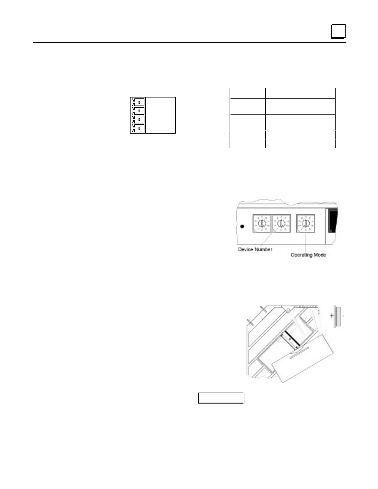
Setting Number Switches
Number switch settings on the Panel Controller can be set using a small flathead screwdriver to
turn the switch dial to the desired setting (so that the arrow points at the desired setting).
Caution
The assembled Panel configuration provides minimal space to reach the number switches once the
Panel is installed. If possible, these settings should be made before the Controller is installed.
2 - 2 PANELWARE MMI Application Manual for Genius Protocol - June 1995 GFK-1115
Page 17
2
Genius Panel Controller (C400)
Specifications
GENIUS
SHLD OUT
SHLD IN
7.165"
X2
(182mm)
X1
a45517
2.165"
(55mm)
7.165"
(182mm)
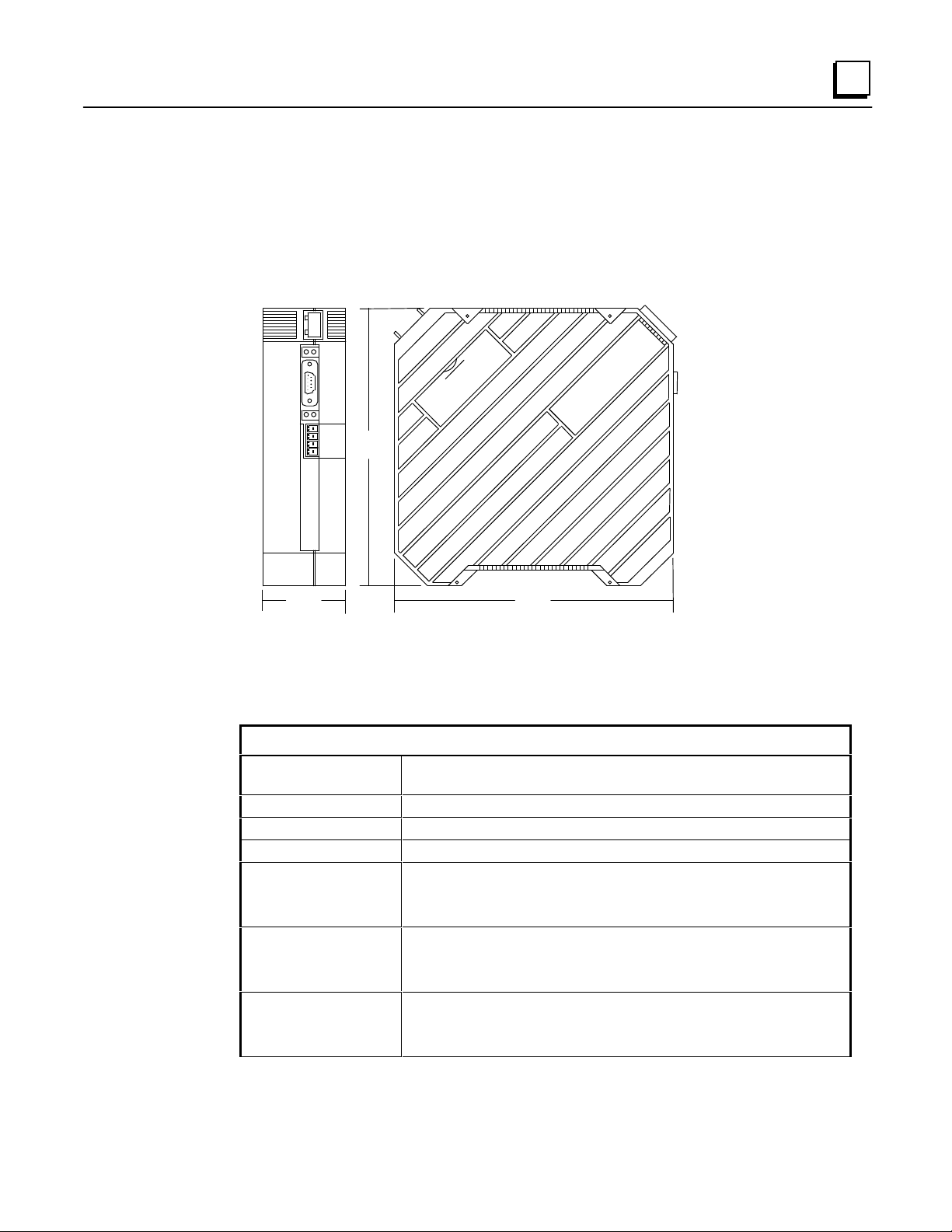
Figure 2 - 1. Genius Panel Controller (C400)
Table 2 - 1. Specifications for Genius Panel Controller (C400)
Technical Data
Interfaces
Programming
Power supply
Real-time clock
Connection of ....
Display modules
Keyblock modules
Temperature
Operating
Storage
Relative humidity
Operating
Storage
IF0: RS-232 (not galvanically isolated)
Genius: (isolated)
PANELWARE Configuration Software
24 VDC (min. 18 VDC, max. 30 VDC)
YES with battery installed (non-volatile)
1
maximum of 7
0 to 50 °C (32 to 122 °F)
-20 to 60 °C (-4 to 140 °F)
10 to 95 % (non-condensing)
10 to 95 % (non-condensing)
GFK-1115 Chapter 2 C400 Panel Controller Hardware 2 - 3
Page 18
2
Table 2 - 1. - Continued
Shock
Vibration
Processor
24 VDC power
requirements
(typical)
Sealing
Noise immunity
conforms to IEC 68-2-27
15g equivalent, 150 m/sec
2
, 11 msec, 3 axes (positive and
negative)
conforms to IEC 68-2-6
1g equivalent, 10-58 Hz; 0.075 mm
58-150 Hz; 9.8m/sec
2
20 cycles per axis
Motorola 68302 @ 16 MHz
185 mA, 24 VDC
260 mA, 18 VDC (minimum power voltage)
150 mA, 30 VDC (maximum power voltage)
NEMA 12 and IP54 when properly mounted in a Panel
conforms to IEC 801.2; IEC 801.3; IEC 801.4
2 - 4 PANELWARE MMI Application Manual for Genius Protocol - June 1995 GFK-1115
Page 19

2
Overview of Connections and Operational Elements
1
9
8
7
6
5
Figure 2 - 2. Genius Panel Controller (C400) Elements/Connections
. Display Module Connector (ribbon
1
cable)
2
. 24 VDC Power Supply Connector
3
. IF0: RS-232 (to PC), labeled 0
4
. Genius Bus Connector
6
. Mode Switch - Operating Mode
7
. Cover for Lithium Battery
8
. Device Number Switches
9
. Reset Button
a45516
2
3
4
5
. Keyblock Module Connector
GFK-1115 Chapter 2 C400 Panel Controller Hardware 2 - 5
Page 20

2
Description
+24 V
0 V
Ground
Ground
24 VDC Power Supply (item 2, Figure 2-2)
Pin
+
-
The pins are to be connected using as short a cable as is possible. If the Panel is mounted in a
cabinet, the connecting cable should be as short as possible.
IF0 - RS-232, Non-isolated (item 3, Figure 2-2)
Pin Description
1NC
2 RxD Receive Data (Input)
3 TxD Transmit Data (Output)
9 pin D-Type (M)
LED Meaning
TxD Send data over interface
RxD Receive data over interface
4 + 5 V Power Supply
5 GND Signal Ground
6NC
7 RTS Request To Send (Input)
8 CTS Clear To Send (Output)
9NC
(200 mA available to user)
2 - 6 PANELWARE MMI Application Manual for Genius Protocol - June 1995 GFK-1115
Page 21
2
Genius Bus Connector, Isolated (item 4, Figure 2-2)
a45318
SHLD OUT
SHLD IN
GENIUS
X2
X1
Pin Description
SHLD OUT Shield Out (to next physical
device on bus)
SHLD IN Shield In (from previous
physical device on bus)
X2 Serial 2
X1 Serial 1
Mode Switch (item 6, Figure 2-2)
The mode of operation for the Panel Controller is
selected by setting the Operating Mode switch (see
Table 2-2 for operating modes).
Device Number Switches (item 8, Figure 2-2)
The Genius bus address for the C400 Controller is set using the Device Number switches. Valid
device numbers are 00 to 31, inclusive.
Lithium Battery (item 7, Figure 2-2)
The lithium battery is stored in its own compartment in
the Controller and covered for its own and the user's
protection. It should be replaced every two years, or
whenever the software indicates that the battery is low.
Warning
Lithium batteries are considered harmful waste. Dispose of them in
accordance with the instructions in the Material Safety Data Sheet (MSDS)
that accompany the battery, and in accordance with local regulations.
GFK-1115 Chapter 2 C400 Panel Controller Hardware 2 - 7
Page 22
2
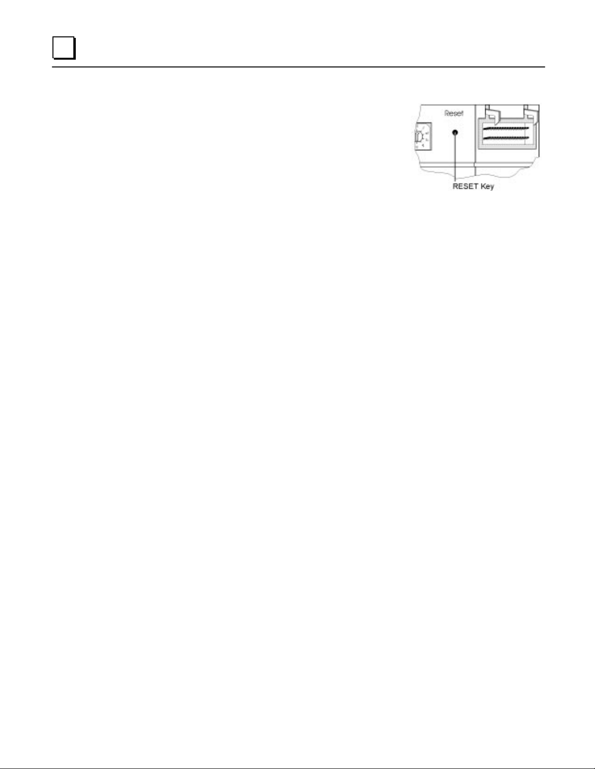
Reset Button (item 9, Figure 2-2)
A hardware reset can be executed by pressing this button.
Depending on the setting of the mode selection switch,
different functions can be executed. These functions are
explained in the descriptions of the connections and
operational elements that follow.
2 - 8 PANELWARE MMI Application Manual for Genius Protocol - June 1995 GFK-1115
Page 23

2
Operating the C400 Controller
FlashPROM
The Panel Controller has non-volatile memory called FlashPROM, which is split into two separate
areas (banks) as follows:
System Bank contains the operating system, which is necessary for the Panel program created by
the user to be processed. The system bank can not be deleted by the user.
Routine operating system updates to a higher revision level are performed with PCS in Update-
Mode.
User Bank contains the Panel program that controls and is used by the display and Keyblock
modules. The Panel program is created with PCS on a standard PC and downloaded in Teach-
Mode.
RESET Modes
After a Reset or power-on, different operating modes can be activated depending on the settings of
the mode switch (operating mode). The mode swi tch is us ed t o select run, update, or teach mode. In
addition, se ttings 1 — 5 selec t the baudrate in run mode.
Table 2 - 2. C400 Controller Mode Switch Settings
Switch
Setting
1
2
3
4
5
6
7
8-9
Run Mode: The Panel Controller starts the operating system from the FlashPROM (Bank
0). Existing Panel programs (in FlashPROM User Bank) are started automatically.
Run Mode, 153.6 kBaud extended
Run Mode, 76.8 kBaud
Run Mode, 38.4 kBaud
Run Mode, 153.6 kBaud standard
Run Mode, 153.6 kBaud standard, or the baudrate set in
PCS
Update Mode: An update of the operating system can be
performed with PCS.
Teach Mode: Panel programs that are created by means
of PCS are transferred to the FlashPROM (User Bank)
Not allowed
Description
GFK-1115 Chapter 2 C400 Panel Controller Hardware 2 - 9
Page 24

2
Loading and Starting Panel Programs
A Panel program is created using PCS and then transferred (loaded) to the Panel through the
serial interface when Teach Mode is selected. To start an application, RUN Mode must be
selected. The following sections outline how to load, start, and reload the operating system.
Loading the Panel Program
1. Connect the PC (COM1 or COM2) to the Panel Controller (always IF0) using the
appropriate serial cable (see Appendix A).
If you are using a printer with the C400, the printer must be disconnected while
the Panel program is loaded.
2
. Select Teach Mode (position 7).
. Press the Reset button.
3
. Wait until Teach-Mode is displayed.
4
Note
. Start the transfer from PCS.
5
. Wait until PCS acknowledges that the entire Panel program has been transferred.
6
Starting the Panel Program
1. Select Run Mode (position 5, or 1 — 4, as appropriate).
. Connect the PLC to the Panel Controller.
2
. Press the Reset button.
3
Update Mode/Reloading the Operating System
The Panel Controller's operating system can be reloaded from PCS. The steps for accomplishing
this transfer are identical to those in the section, “Loading the Panel Program,” except that
Update Mode (position 6) is selected. The Update Mode is only required to support future
operating system upgrades.
To update in this mode, proceed as follows:
1. Select Update Mode (position 6).
2. Press the Reset button.
3. Begin the update operation with PCS.
4. Wait until PCS acknowledges that the update is complete.
5. Select Run Mode (position 5, or 1 — 4, as appropriate).
6. Press the Reset button to start the existing Panel program.
2 - 10 PANELWARE MMI Application Manual for Genius Protocol - June 1995 GFK-1115
Page 25

Chapter
3
Quick Start
This chapter provides a quick guide to installing and using PCS and, using step-by-step
instructions, explains how to create a project. It includes the following information:
■ Software Installation........................3-2
❏ Calling the Setup Program........3-2
❏ Language Selection................... 3-2
❏ Installation Menu .... ............. ....3-3
■ Starting PCS ...................................3-5
■ General Operation...........................3-6
❏ Pull-down Menus...............3-6
❏ Window Name...................3-6
❏ Selection Windows ............3-7
❏ Context-Sensitive Help ......3-7
❏ Screen Elements................3-8
■ PCS Configuration ..........................3-9
■ Creating a New Project..................3-10
■ Defining Connections....................3-14
❏ PLC ↔ Panel Connection.......3-15
❏ Connection to a GE Fanuc PLC
via Genius.............................. 3-15
❏ Internal Connection ............... 3-18
❏ Genius Internal Connection.... 3-19
■ Key Assignments .......................... 3-20
■ Creating Pictures .......................... 3-22
■ Defining the Project Variables ...... 3-29
■ Binding Pictures in the Project...... 3-33
❏ Communications Error Picture 3-34
❏ Picture Binding Overview...... 3-35
❏ Picture List Organization....... 3-39
■ Compiling the Project ................... 3-40
■ Downloading the Project............... 3-41
■ Starting the Project ....................... 3-44
■ Exiting the PCS ............................ 3-45
GFK-1115 3 - 1
Page 26

3
Section 1 Software Installation
The Genius protocol driver is copied to your computer as part of the standard PCS installation
(PCS version 1.8 or later). The PCS should be installed according to the instructions in the
following sections.
Calling the Setup Program
Insert the PCS distribution diskette into the appropriate floppy disk drive. If you are using the two
3 1/2” diskettes, install the #1 disk first (the system will prompt you when it is time to insert disk
#2).
Depending on the floppy drive designation (a or b), type one of the following commands at the
DOS prompt, then press the ↵↵ (Enter) key:
C:\>
a:setup
or
After you press ↵↵ , the setup program is called and the menu for language selection appears on the
screen.
Language Selection
The Language Selection menu is used to select the language (English or German/Deutsch) in
which you wish to configure the PCS during the installation procedure. This language is used as
the default selection for the PCS.
Press the function key that corresponds to the desired language. When it has been selected, the
Install Program menu is displayed on the screen.
C:\>
b:setup
3 - 2 PANELWARE MMI Application Manual for GE Fanuc Genius Protocol - June 1995 GFK-1115
Page 27
3
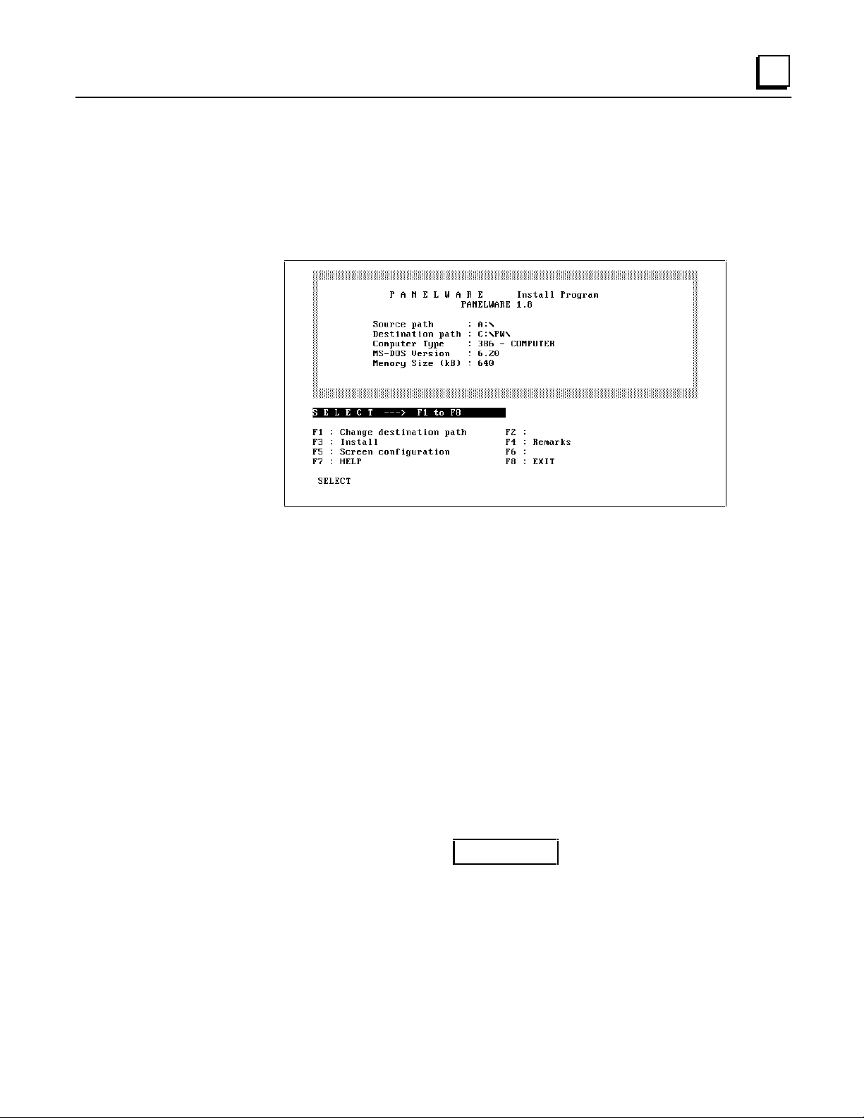
Installation Menu
All system information that the software requires is entered or displayed in the Install Program
menu. Computer type, DOS version, source path and memory size are entered automatically. You
must enter the desired destination path.
From the Install Program menu, you can change destination paths, start the installation,
configure the screen, and exit the installation.
Changing the Destination Path
The destination path (the directory in which the software is to be installed) is set to C:\PW\ by
default. By pressing F1 Change destination path, you can specify a different disk drive and/or
path into which the PCS will be installed.
Start Installation
Once the system information is correct in the Install Program menu, start the installation process
by pressing F3 Install.
The setup program may recommend changes to the CONFIG.SYS file. These changes are only
made if you confirm them at the prompt.
The PCS requires the minimum values recommended for FILES and
BUFFERS. If you enter smaller values in the CONFIG.SYS file, problems
could arise while running the PCS.
Caution
GFK-1115 Chapter 3 Quick Start 3 - 3
Page 28
3
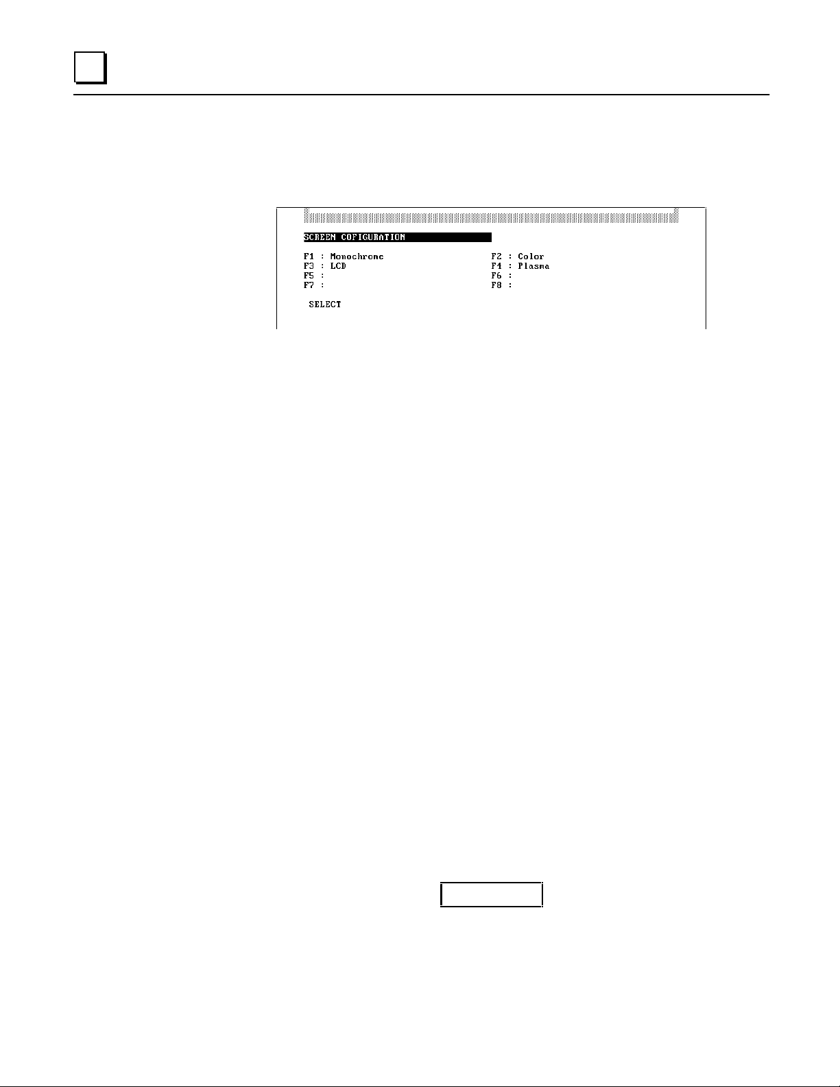
Screen Configuration
The Screen Configuration menu is displayed once the CONFIG.SYS file changes are made.
This screen allows you to set up the appropriate PCS screen type by pressing the function key that
corresponds to your computer's display. When you select a display type, the system begins copying
the PCS files to the destination directory you selected.
After all PCS installation files are copied to the destination directory, the following message is
displayed:
Installation completed. Press any key to continue _
The Install Program menu reappears on the screen when any key is pressed.
If the screen type that was selected during installation must be changed after
installation, you can access the Screen Configuration menu again by pressing
F5 Screen configuration from the Install Program menu and selecting the
desired screen type.
Exiting the Installation
The setup (installation) program is exited when you press F8 EXIT from any of the menus. Before
exiting, the following message will appear on the screen if changes were made to the
CONFIG.SYS file:
System file modified: RE-BOOT (Y/N)?
To start the PCS properly, it is necessary to reboot the computer after installation when changes
have been made to the CONFIG.SYS file.
Remove the distribution diskette from the floppy drive and press
to put the changes to the CONFIG.SYS file into immediate effect. If you do not remove the
diskette from the floppy drive, the system will reboot from the floppy drive rather than the hard
drive.
Note
Y
to reboot the computer in order
Caution
During the installation process, a batch file called PANEL.BAT is created
in the root directory of your hard disk. This file should never be deleted,
because it is used to access the PCS.
3 - 4 PANELWARE MMI Application Manual for GE Fanuc Genius Protocol - June 1995 GFK-1115
Page 29

3
Section 2 Starting PCS
To start PCS, type the following command at the C: prompt, then press ↵↵ (if you installed the
software on a drive other than C, substitute the correct drive ID for C:):
C:\>panel
The PCS is called up and the following copyright information is displayed on the screen:
After a delay, the Main menu, with its pull-down menu line and messages, is displayed:
GFK-1115 Chapter 3 Quick Start 3 - 5
Page 30
3
Section 3 General Operation
Pull-Down Menus (Main Menu)
The pull-down menus of the Main menu can be opened at any time using two different methods:
■ By pressing the alternate (Alt) key simultaneously with the desired function key (F1 to
F5)
■ By pressing the Alt key simultaneously with the first letter of the desired menu name
For example, the F1 File menu can be opened by pressing either Alt + F1 or Alt + F.
Once a menu is open, select the desired option by highlighting it using the cursor keys and
pressing ↵↵. Any resulting window that the option calls up will be displayed in the blank window
of the Main menu, with its associated function key line displayed below.
Key shortcuts (hot keys) for specific menu entries are displayed on the menu next to the associated
entry.
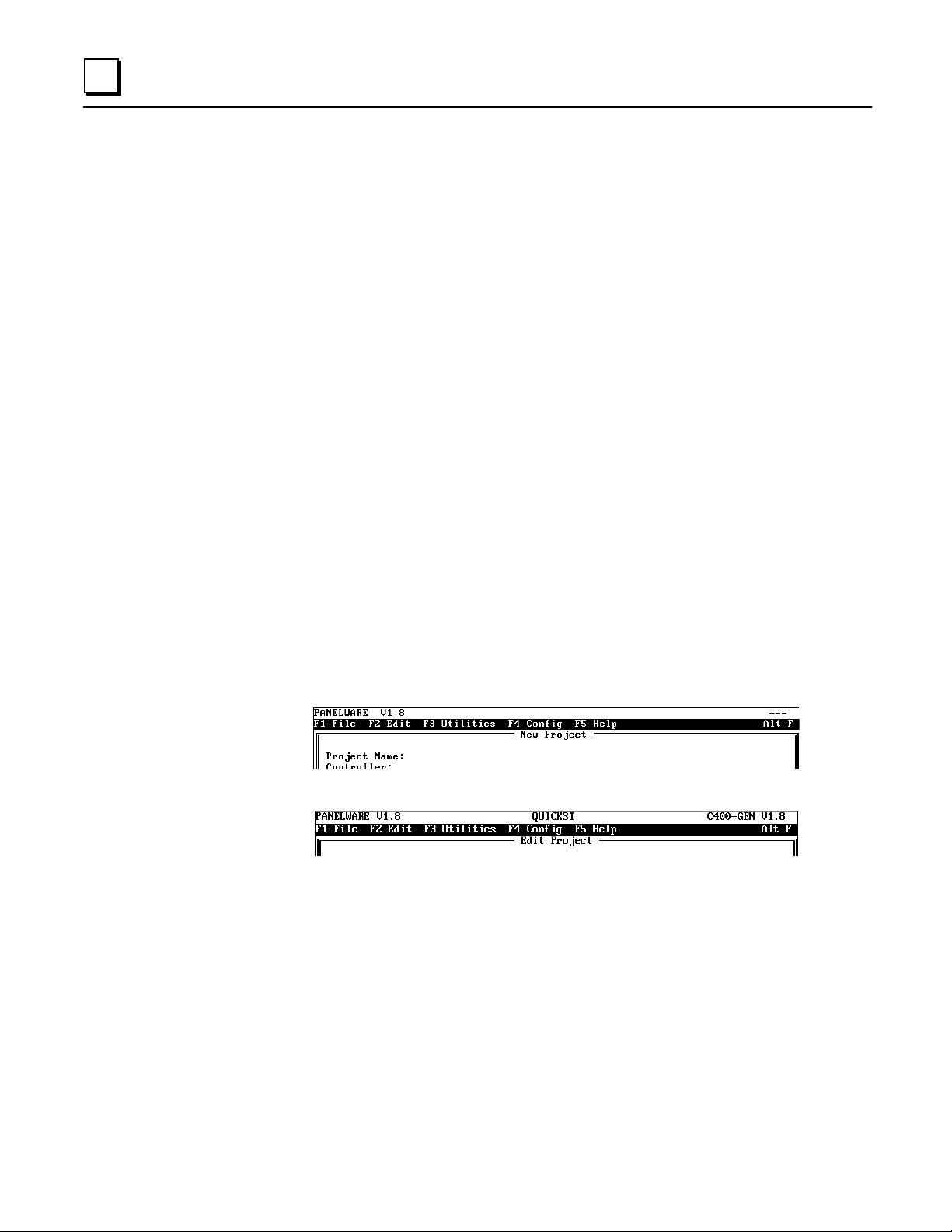
Window Name
Every window that can be displayed within the Main menu has a name that is centered inside the
top line margin of the window. For example:
■ Window name New Project
■ Window name Edit Project
3 - 6 PANELWARE MMI Application Manual for GE Fanuc Genius Protocol - June 1995 GFK-1115
Page 31

3
Selection Windows
If the ↵↵ character is displayed in the bottom line of a screen, a selection window can be opened by
pressing the enter (↵↵) key. A selection can be made from these windows by moving through the
list using the cursor keys until the desired entry is highlighted, then pressing ↵↵.
Context-Sensitive Help Screens
While using the PCS, context-sensitive help screens can be accessed at any time. If you press
Alt + F5 or ALT + H while working in the PCS environment, a help screen that corresponds to
the current PCS function/activity is displayed. Using the PgUp or PgDn keys, you can flip forward
or backward through the help screens. If all of the help text in a Help screen can not be seen, the ↑↑
and ↓↓ (Cursor Up/Down) keys can be used to scroll through to the end.
On some Help screens, related (cross-referenced) help may be signaled by the presence of one or
more Help screen numbers. These cross-references are indicated with the respective Help screen
number displayed between the < and > characters (e.g., Help Screen <0000>). The first of these
numbers will be highlighted. The Tab and BackTab keys can be used to highlight a different
screen number, then when you press ↵↵, that highlighted Help screen will be displayed. The Alt +
F1 key returns you to the previous Help screen level. Pressing F10 returns you to the first Help
screen <0000> at any time. The following example shows a typical Help screen:
To exit any Help screen, press Esc.
GFK-1115 Chapter 3 Quick Start 3 - 7
Page 32

3
Screen Elements
The PCS display contains a few basic elements that are displayed at all times:
Figure 3 - 1. Basic PCS Screen Elements
■ In the top line (title line) of the screen, the software version number is displayed at the left,
the name of the current project is in the middle, and the Panel Controller description (type
and operating system version) is on the right.
■ The next line down (menu line) contains the headings of the pull-down menus.
■ The second to the last line (function line) of the screen displays the current function key
assignments.
■ The bottom line (message line) contains any error messages, important notices that relate to
the project, or the character ↵↵, which indicates that a selection window can be accessed.
3 - 8 PANELWARE MMI Application Manual for GE Fanuc Genius Protocol - June 1995 GFK-1115
Page 33

3
Section 4 PCS Configuration
Before you can begin creating projects using the PCS, the appropriate interface to be used to
connect your PC to the PANELWARE controller must be defined. The F4 Config. pull-down
menu shown below can be opened by pressing Alt + F4 or Alt + C:
To set up the interface, select the Channel #2 command by highlighting the entry and pressing ↵↵
. This opens a window that allows you to choose from several options. At this point, you are only
concerned with selecting an interface. When you highlight the Interface option, it is displayed
inversely in the window and is selected by pressing ↵↵.
In a selection window, you can choose whether you want to use COM1 or COM2 as the PC
interface to be used for programming the C400 Panel Controller. The Network setting is for
future expansion.
Once a serial interface, e.g., COM2, is selected, the Panel Controller can be connected to this
interface using a serial interface cable (see the PANELWARE Hardware Installation User's
Manual — GFK-0848).
Note
The remaining Channel #2 options should be left at their default settings until
you have successfully downloaded a project to the Panel Controller. See the
PANELWARE Configuration Software Reference Manual (GFK-0849) for
details on all of the Channel #2 configuration items.
GFK-1115 Chapter 3 Quick Start 3 - 9
Page 34

3
Section 5 Creating a New Project
Throughout the remainder of this chapter, you will create an example project (named QUICKST)
by following the steps that are outlined in the text. This sample project is designed to provide an
overview of how the PCS works.
The following minimum hardware setup is required to execute the sample project you will create:
❏ one C400 Panel Controller
❏ one 4 x 20 LCD display module
❏ one 16-key Keyblock module
❏ one numeric (12+4) Keyblock module
❏ one PLC capable of Genius communications
Assemble the modules according to the instructions in the PANELWARE™ Hardware Installation
User's Manual (GFK-0848) so that the numeric Keyblock module is the one to be connected to the
Panel Controller.
Note
Although your hardware configuration may be different than that specified
above, creating the example project is still recommended as it will introduce you
to the basic techniques you will need to use for any hardware configuration.
To create a new project, access the F1 File menu by pressing either the Alt + F1 or Alt + F key
combination. Select the New Project menu option using the cursor keys:
When the New Project option is highlighted inversely within the menu, press ↵↵ to open the New
Project window, in which the project name and the type of Panel Controller to be used are
entered.
Use the keyboard to type the desired name of the project (QUICKST) in the current cursor
position. Press ↵↵ to accept the name and the cursor moves to the next line, where the type of
controller can be defined.
3 - 10 PANELWARE MMI Application Manual for GE Fanuc Genius Protocol - June 1995 GFK-1115
Page 35

3
Press ↵↵ again to open a selection window that contains a list of the available Controllers.
Note
The available Controllers are listed in the form <type>.#<OS version>, where
<type> is the basic controller model (e.g., C400) and <OS version> is the
operating system version number (e.g., V1.8).
When you press ↵↵, the controller selection (C400-GEN.#18 in the example above) is confirmed.
Another window appears on the screen from which the display and Keyblock module types can be
configured.
Caution
Both the controller and the display type must be defined when creating a
new project. Once selected, you CAN NOT change them. You should know
which controller and display type will be used before the project creation
process is started.
GFK-1115 Chapter 3 Quick Start 3 - 11
Page 36

3
Select the Display Type entry and press ↵↵ to display a window
that lists all display types. Select one of the display types (in the
example, LCD 4x20) and press ↵↵.
The cursor jumps to the next line, Number of Keyblock
Modules. Enter a number (1 through 7) and press ↵↵ to confirm
the number of Keyblock modules in your configuration (e.g., 2).
The next step is to define the individual Keyblock modules (not all of the
modules in the list have to be defined). When the cursor is in one of the
Type Keyblock Module x lines, you can access a selection window that
lists the Keyblock modules by pressing ↵↵.
For this example, select the numeric (12+4) and the 16-key Keyblock modules as Keyblocks 1 and
2, respectively. The following table defines the numbers in the Keyblock Module selection
window:
Table 3 - 1. Keyblock Module Definitions
List Entry Keyblock Module
16 16-key Keyblock module
12+4 Numeric Keyblock module
8 8-key Keyblock module
4 4-key Keyblock module
3 - 12 PANELWARE MMI Application Manual for GE Fanuc Genius Protocol - June 1995 GFK-1115
Page 37

3
The new project definition can be saved and closed by pressing the F4 Accept function key. While
the system is saving the project, the following screen is displayed:
After the project is saved, the New Project window is closed and the project name (QUICKST) is
displayed in the title line.
GFK-1115 Chapter 3 Quick Start 3 - 13
Page 38

3
Section 6 Defining Connections
The next step after creating a new project is to define the connections. All PLCs and other devices
that are to communicate with the Panel must be entered in the connection editor. To change or
insert connections, select the Connection option from the Edit menu.
The following window, Connection List displays all entered connections:
When creating a new project for the C400-Genius Controller, a default entry with the ID, DD, is
made automatically (connection to a GE Fanuc PLC via the Genius bus). However, the associated
PLC type is not defaulted and must be specified.
3 - 14 PANELWARE MMI Application Manual for GE Fanuc Genius Protocol - June 1995 GFK-1115
Page 39

3
Connection to a GE Fanuc PLC via Genius
Press F1 Edit to edit the connection DD Genius:
Move the cursor to the PLC Type line using the →→ or ↵↵ key:
The PLC type to communicate with can be chosen from this selection window. For this example,
use the cursor keys to highlight the entry GBC Series 90-70 and press the ↵↵ key, closing the
selection window.
GFK-1115 Chapter 3 Quick Start 3 - 15
Page 40

3
The Connection Definition window containing the new connection is displayed.
By pressing F4 Accept, the change is confirmed and shown in the Connection List window:
To configure the Genius bus aspects of the connection, press the F4 PLC Node Parameters Key.
3 - 16 PANELWARE MMI Application Manual for GE Fanuc Genius Protocol - June 1995 GFK-1115
Page 41

3
Here, the Target device number, or Genius bus address, of the connection is specified. Enter the
bus address of your GBC (typically bus address 31) in the Target device number field.
No other data needs to be entered into the PLC Node Parameter Definition screen for this
example. Pressing F4 Accept completes the entry
GFK-1115 Chapter 3 Quick Start 3 - 17
Page 42

3
Internal Connection
Now insert an internal connection into the connection list. This is done by first pressing the F2
Ins key and then specifying the ID DI in the window that appears.
Choose Internal as the connection. Press F4 to confirm this definition and see it displayed in the
Connection List window.
3 - 18 PANELWARE MMI Application Manual for GE Fanuc Genius Protocol - June 1995 GFK-1115
Page 43

3
Genius Internal Connection
As a final connection, insert a Genius internal connection into the connection list. this is done by
first pressing the F2 Ins key and then specifying the ID GI in the window that appears. Choose
Genius as the Connection and Genius Internal as the PLC Type. This definition is now
confirmed and the new connection displayed in the connection list upon pressing the F4 Accept
key.
GFK-1115 Chapter 3 Quick Start 3 - 19
Page 44

3
Section 7 Key Assignments
Every key on every Keyblock module can be defined according to the project's unique needs. You
can also assign keys for numbers, letters, and the Next and Previous functions.
In order to assign functions to the keys, the Edit Keycode Table window must be accessed by
selecting the Keyboard option from the F2 Edit pull-down menu or by pressing Ctrl + K:
The Edit Keycode Table window shown below is displayed (the default keycode settings that are
shown will work for this example project):
Save the key assignments by pressing the F10 Exit function key.
3 - 20 PANELWARE MMI Application Manual for GE Fanuc Genius Protocol - June 1995 GFK-1115
Page 45

3
The abbreviations on the Keyblock module keys have the following meanings:
Table 3 - 2. Keyblock Abbreviation Definitions
Abbr. Description
F1 ... F4 Function keys 1 through 4 (used for commands and picture changes)
+p+ Moves cursor to the previous INPUT field
+n+ Moves cursor to the next INPUT field
+P+ Changes to the previous picture
+N+ Changes to the next picture
+G+ Global alarm acknowledgment
+B+ Backspace; deletes the character before the cursor in an INPUT field
+S+ Changes the sign in a numerical INPUT field
+E+
+C+
. Decimal point
0 ... 9 Numbers 0 - 9 for the entry of numbers
Enter key; transmits the value entered in an INPUT field; labeled as ↵↵ on
actual Keyblock
Cancels (deletes) an INPUT field; labeled as ← on actual Keyblock
GFK-1115 Chapter 3 Quick Start 3 - 21
Page 46

3
Section 8 Creating Pictures
Picture 1
Pictures make up the basic elements of every Panel project. They include static elements such as
text and lines
information, such as temperature, RPM, etc., to be updated and displayed for the user. Input fields
can be used to display entries given to the process that you enter using the keyboard.
A project must contain at least two pictures—one picture that displays when the Panel powers up,
and another that displays in the event of a communications failure. This example project will
contain three pictures, as follows:
1. Picture 1 is the picture where values will be entered using the keyboard, transmitted to the
PLC and output in another field.
2. Picture 2 is the start-up picture that is to be displayed when the Panel and PLC are switched
on. Only the Panel’s date and time, and the scan rate of the Genius bus will be displayed.
3. Picture 3 is displayed if there is a communications failure between the PLC and the Panel.
Only text providing notice of a communications error will be displayed in this picture.
To edit or create a picture using the picture editor, select the Picture option from the F2 Edit
pull-down menu or press Ctrl + B.
1
, and/or dynamic elements like input and output fields. Output fields allow
1
Lines can only be inserted in a picture if a graphic display has been selected in the project
definition. See the PANELWARE™ Hardware Installation User's Manual (GFK-0848) for a
list of available graphic displays.
3 - 22 PANELWARE MMI Application Manual for GE Fanuc Genius Protocol - June 1995 GFK-1115
Page 47

3
The blank Edit Picture window shown below is displayed:
The size of the dark rectangle (picture) at the bottom of the screen corresponds to the selected
display type (display type LCD 4x20 is shown above, i.e., the rectangle consists of 4 lines and 20
characters per line). Text or fields can now be entered into this rectangle.
In the first line, enter the text
Move the cursor to position (3,0) (the current cursor position is indicated in the lower right-hand
corner of the screen as Column/Row). A text field can now be created simply by typing in the
desired text (
function key and then entering the desired text.
As long as the cursor is within this text field, the field is displayed inversely (on color monitors it
has a red background). Press ↵↵ to complete the text field. The inverse display is switched off and
the text is displayed normally.
Move down to lines 2 and 3, and enter the following text:
Next to the Output: text, begin creating an output field by moving the cursor to the following
position (8,2):
Input / Output
Input / Output
). It is also possible to start a text field by pressing the F1 Text
as follows:
GFK-1115 Chapter 3 Quick Start 3 - 23
Page 48

3
Press the F2 Field function key to open the Field Class selection window.
Select the Output Field entry from the list and press ↵↵ to access the Select Field Type window.
Several output field types can be chosen from this widow:
For this example, select the Output Word (signed) field type. This results in a data entry form
(with default entries) being opened on the screen.
In the Output Word window, change the following entries as shown by highlighting them using
the cursor keys, then typing the new text:
Places after dec. point:
Tagname:
2
VALUE1
Note
To complete an entry, you must press ↵↵. If you change an entry and then press a
cursor key instead, your entry will be ignored and the previous contents of the
entry will be restored.
VALUE1 is a symbolic name for a memory location in the PLC. Assigning symbolic names to the
actual PLC addresses is accomplished using the connection editor.
Press the F4 Accept function key to close the field and confirm it as part of the picture. The field
should be displayed within the picture:
3 - 24 PANELWARE MMI Application Manual for GE Fanuc Genius Protocol - June 1995 GFK-1115
Page 49

3
Move the cursor to the Input: text line and press the F2 Field function key. Select the Input
field option from the Field Class window that is displayed:
The Select Field Type window containing all of the input field types is displayed.
For this example, select the Input Word (signed) field type:
In the Input Word window that is displayed, change the following entries as shown by
highlighting them using the cursor keys, then typing the new text:
Places after dec. point:
Tagname:
Press the F4 Accept function key to close the field and confirm it as part of the picture. The field
should be displayed within the picture as shown below:
2
VALUE1
GFK-1115 Chapter 3 Quick Start 3 - 25
Page 50

3
Press the F10 Exit function key to end this picture editing session. Because this is a new picture, a
window will open to confirm whether or not the picture should be saved:
Type Y to request that the picture be saved, and a prompt will request you to enter the filename
under which the picture will be saved:
Type the desired filename using the keyboard (e.g., PICT_1). PCS saves the picture under the
filename you type and assigns a .BIL extension (e.g., PICT_1.BIL) automatically when you
press ↵↵.
Picture 2
Picture 2 will serve as the start-up picture for the project.
Access the picture editor by selecting the Picture option from the F2 Edit pull-down menu or by
pressing Ctrl + B.
In line 1 of the rectangle, type the text
Move the cursor to position (1,2) and press the F2 Field function key, then select the Output
Field option from the Field Class window:
*** Start-up Pict ***
and press ↵↵.
3 - 26 PANELWARE MMI Application Manual for GE Fanuc Genius Protocol - June 1995 GFK-1115
Page 51

3
From the Select field type window that is displayed, select the Output Date/Time option:
The output format for the date and time is selected from the following window that is displayed:
Do not make any changes in this window and press the F4 Accept function key. The Date/Time
field will be displayed in the start-up picture:
Move the cursor to position (1,3), type the text
to position (16,3), type the text
Using the same process detailed above for creating the Output Date/Time field, position the cursor
at (11,3), and create an Output Word (unsigned) field with the following definition:
GFK-1115 Chapter 3 Quick Start 3 - 27
ms
, and again press ↵↵.
Bus Scan:
, and press ↵↵. Next, move the cursor
Page 52

3
Picture 3
Press the F4 Accept key to close the field and confirm it as part of the picture. The field should be
displayed within the picture as shown below:
Press the F10 Exit function key to end this picture editing session. Because this is a new picture, a
window will open to confirm whether or not the picture should be saved.
Type
Y
to request that the picture be saved, then type the desired filename (START-UP) using the
keyboard. The picture is saved under the name you type and assigned a .BIL extension
automatically when you press ↵↵.
An error picture that will display on any communication error is created in exactly the same way
as any other picture. Input or output fields that would access variables from the PLC are of no use,
however, because the error picture is supposed to show an error in communications. Internal
variables can be shown (e.g., error variables that are used to display the type of communications
error). See the PANELWARE™ Configuration Software Reference Manual (GFK-0849) for
details.
Using the steps followed to create the first two pictures, create the following error picture and save
it under the name ERROR:
The Output Bit/Byte field in the picture is defined as follows:
3 - 28 PANELWARE MMI Application Manual for GE Fanuc Genius Protocol - June 1995 GFK-1115
Page 53

3
Section 9 Defining the Project Variables
All variables used in the project (symbolic variable names) must be connected to specific
addresses in the PLC CPU.
In order to define these connections, access the connection list by selecting the Connection option
from the F2 Edit pull-down menu or by pressing Ctrl + C.
The Connection List window shown below is opened:
GFK-1115 Chapter 3 Quick Start 3 - 29
Page 54

3
Genius Device Connection
Use the cursor keys to highlight connection DD Genius, and then press the F5 VAT function key
to display the associated variable assignment table (VAT) on the screen.
All variables that have been used in a picture's input or output fields in the project are listed in the
Variable Assignment Table window. In this example project, only one name, VALUE1, is
displayed:
To assign an address in the PLC CPU to the VALUE1 variable, press the F1 Edit function key.
The VAT Definition window shown below is opened:
The PLC address can be entered directly at the PLC Address line using the keyboard (e.g.,
%R0100
If the cursor is in the PLC Variable Type line, a variable type selection
window that shows all valid variable types can be opened by pressing ↵↵.
Select DINT from the selection window.
).
3 - 30 PANELWARE MMI Application Manual for GE Fanuc Genius Protocol - June 1995 GFK-1115
Page 55

3
The definition that is entered can be saved by pressing the F4 Accept function key. Once saved,
the newly selected variable is shown in the VAT.
Pressing the F10 Exit function key causes the connection list to appear on the screen again.
Genius Internal Connection
Select the GE Genius Internal connection from the connection list and press either F5 VAT or ↵↵
to display the connection in the Variable Assignment Table:
Press the F1 Edit function key to open the VAT Definition window for the GENIUS_BUS
tagname. Edit the definition for GENIUS_BUS as shown below (Follow the same procedure that
was used for editing the tagname VALUE1 in the DD connection
After accepting the entry (by pressing F4), press F10 Exit to return to the Connection List
window.
GFK-1115 Chapter 3 Quick Start 3 - 31
— see page 30):
Page 56

3
Internal Connection
Select the DI Internal connection from the connection list and press F5 or ↵↵ to view its VAT:
This is the variable that will be output in the error picture. The internal variables cannot be edited.
You can close the VAT by pressing F10 Exit, which calls the connection list once again. Press the
F10 Exit key again to close the connection list and return to the main menu.
3 - 32 PANELWARE MMI Application Manual for GE Fanuc Genius Protocol - June 1995 GFK-1115
Page 57

3
Section 10 Binding Pictures in the Project
The pictures that you have created for this project still have to be bound into the project definition.
To begin the binding process, select the Project option from the F2 Edit pull-down menu or press
Ctrl + P.
The Edit Project window shown below is opened:
The picture binding process for this project consists of the following three steps:
1. Entering the filename of the ERROR picture
2. Binding the three project pictures
3. Organizing the picture directory
These processes are explained in the sections that follow.
GFK-1115 Chapter 3 Quick Start 3 - 33
Page 58

3
Picture for a Communications Error
From the Edit Project window, press the F1 Project Def. function key to move the cursor to the
Picture for Communications Error line in the window. The function line options are changed as
shown below:
The file name of the error picture can be entered directly using the keyboard or the following
selection window can be accessed by pressing the F5 Pictures function key.
Highlight the desired filename (ERROR.BIL) and press ↵↵, then confirm the project definition by
pressing the F4 Accept function key.
3 - 34 PANELWARE MMI Application Manual for GE Fanuc Genius Protocol - June 1995 GFK-1115
Page 59

3
Picture Binding Overview
Binding a picture into the project means that all possible branches (picture changes) that the
picture can have are defined. A picture change can be made using the Next, Previous or optional
function keys
When you press the F2 Bind Picture function key from the Edit Project window, the Bind
Picture window appears on the screen:
2
.
When the cursor is located in one of the boxes in the window, a picture name can be entered
directly by using the keyboard or a selection window containing picture names can be accessed by
pressing the F5 Pictures function key.
In the first box (left-hand side of the screen), enter the name of the picture to be bound into the
project. When you press ↵↵, the picture is accepted and the cursor moves to the upper right-hand
box. You can switch between the upper and lower right-hand boxes using the cursor keys. When
the cursor is in one of the boxes on the right-hand side, the function line at the bottom of the
screen changes as shown below:
Press the F1 Picture name function key to move the cursor back to the box on the left-hand side
of the screen. Use these cursor location controls to bind this project's pictures as described in the
following sections.
2
The user can define keys to be used for Next, Previous or function keys (see “Key
Assignments” in this chapter).
GFK-1115 Chapter 3 Quick Start 3 - 35
Page 60

3
Error Picture
Bind the ERROR picture into the example project as follows:
Caution
You should not branch from the ERROR picture to a picture that has fields
displaying data from the PLC in it because the fields will not be updated or
processed if a communications error occurs.
Save the configuration by pressing the F4 Accept function key.
3 - 36 PANELWARE MMI Application Manual for GE Fanuc Genius Protocol - June 1995 GFK-1115
Page 61

3
Start-up Picture
Bind the START-UP picture into the example project as follows:
If the START-UP picture is bound into the project as shown, the user will be able to switch to the
PICT_1 picture by pressing the Next key on the Panel. The Previous key performs a refresh of the
screen for the START-UP picture.
Save the configuration pressing the F4 Accept function key.
GFK-1115 Chapter 3 Quick Start 3 - 37
Page 62

3
Pict_1
Bind the PICT_1 picture into the example project as follows:
If the PICT_1 picture is bound into the project as shown, the operator will be able to switch back
to the START-UP picture using the Previous key on the Panel. Pressing the Next key causes a
refresh of the screen for the PICT_1 picture. Save the configuration by pressing the F4 Accept
function key.
3 - 38 PANELWARE MMI Application Manual for GE Fanuc Genius Protocol - June 1995 GFK-1115
Page 63

3
Picture List Organization
When you press the F3 Picture List function key from the Edit Project window, a list of all of
the pictures that are bound to the project is displayed:
The picture defined as the ERROR picture is not allowed to be placed in the top position in the
picture list; the picture in the top position must be the one initially displayed when the Panel is
power cycled (start-up picture).
Accordingly, in this example, the ERROR picture must be moved down from its top position in
the list using the F7 Back function key. This will move the item in the current cursor position
down one line in the list, and move the next item one line up as shown below:
The START-UP picture should now be in the correct position (000).
Press the F10 Exit function key to save the changes and redisplay the Edit Project window. Press
F10 Exit again to return to the Main menu.
GFK-1115 Chapter 3 Quick Start 3 - 39
Page 64

3
Section 11 Compiling the Project
In order to create, transfer and run your project on the Panel, it must be compiled (translated).
To compile the example project, select the Compile option from the F3 Utilities pull-down menu
or press Ctrl + Q:
The compilation procedure status messages are displayed in the Project Compiler window that is
displayed. If the project is compiled successfully, the following message is displayed:
The amount of memory the project will occupy in the user memory (user Flash) in the Panel is
also displayed.
Press Esc to close the Project Compiler window and return to the Main menu.
3 - 40 PANELWARE MMI Application Manual for GE Fanuc Genius Protocol - June 1995 GFK-1115
Page 65

3
Section 12 Downloading the Project to the Panel
In order to download a compiled project to the Panel, the Panel must first be connected to the PC.
The connection and the cable that should be used are described in Appendix A of the
PANELWARE™ Hardware Installation User's Manual (GFK-0848).
Caution
Ensure that the cable is connected to the serial interface of the PC that is
defined as Channel #2 in the configuration (COM1 or COM2).
Figure 3 - 2. Panel/PC Serial Connection
Before the download process can be started, the following steps must be completed (see the
PANELWARE Hardware Installation User's Manual for more information):
1. Apply power to the Panel by connecting the 24 VDC cable.
2. Connect the PC and the Panel as shown above.
3. Set the operating mode to Teach-Mode (operating mode switch to position 7).
4. Press the Reset button on the Panel.
Wait until the “Teach-Mode” message is displayed on the Panel screen.
GFK-1115 Chapter 3 Quick Start 3 - 41
Page 66

3
Once these steps have been performed, the download process can be started by selecting the
Download option from the F3 Utilities pull-down menu or by pressing Ctrl + X:
The Download Project title and the number of the channel (Channel #2) are centered in the top
margin of the window that appears on the screen to prompt you to begin the process.
Start the download process by typing Y.
In order to begin the download, the PCS tries to make a connection with the Panel. If the
connection is successful, the following messages are displayed on the screen:
When the compiled project has been loaded to the Panel successfully, the message Download
complete! is displayed.
Press Esc to close the Download Project window and return to the Main menu.
3 - 42 PANELWARE MMI Application Manual for GE Fanuc Genius Protocol - June 1995 GFK-1115
Page 67

3
Section 13 Connecting the PLC and the Panel
In order for communication to take place between the Panel and the PLC, the following
connection must be made:
Figure 3 - 3. PLC/Panel Connection
GFK-1115 Chapter 3 Quick Start 3 - 43
Page 68

3
Section 14 Starting the Project
If the project has been downloaded completely, the application can be started after the following
steps are completed:
1. Set the operating mode to Run-Mode (operating mode switch to position 5).
2. Connect the PLC and the Panel.
3. Press the Reset button on the Panel.
After switching the Panel on or pressing the Reset button, the Start-up picture appears on the
screen:
Press the “Next” key on the Panel, and PICT_1 will appear on the screen:
The inverse display area is an input field in which values can be entered using the numerical keys
(on the numeric Keyblock). After the entry is confirmed by pressing ↵↵, the value that was entered
should appear in the output field above. (See the “Key Assignments” section in this chapter for
individual key descriptions.)
If the connection is not made between the PLC and the Panel, or if it is improperly made (cable
defective, wrong interface, etc.), the following message is displayed shortly after the Reset button
is pressed:
3 - 44 PANELWARE MMI Application Manual for GE Fanuc Genius Protocol - June 1995 GFK-1115
Page 69

3
Section 15 Exiting PCS
If the Main menu is active, the PCS program can be ended by pressing the F10 Exit function key
or by selecting the Exit option from the F1 File pull-down menu. This causes the following
message to appear on the screen.
If you enter Y, the PCS program is exited. If you enter N, the PCS program is not exited and the
Main menu remains active.
If you turn off or reboot your computer before exiting PCS, clusters will be lost
on your hard disk. Lost clusters do not imply that your disk is damaged, only
that there is disk capacity that is unused but not managed by the DOS (operating
system). This condition may be checked for, and corrected, by using the DOS
CHKDSK utility. See your PC's MS-DOS manual for details on running
CHKDSK.
Note
GFK-1115 Chapter 3 Quick Start 3 - 45
Page 70

Chapter
4
Configuring Communication with the PLC
This chapter provides information on how to configure the interfaces of the Panel Controller and
the PLC to make the connection between them. The following information is included:
■ Genius Protocol Parameters (Definition in PCS) .........................................................4-2
❏ PLC Types...........................................................................................................4-3
❏ PLC Node Parameter Definitions.........................................................................4-5
❏ PLC Network Parameter Definitions....................................................................4-7
■ SNP 90 Protocol Parameters (Definition in PCS) ........................................................4-9
■ Settings on the Panel ................................................................................................4-10
■ Panel Interface.......................................................................................................... 4-10
■ Configuration of the PLC Interface...........................................................................4-10
❏ Genius............................................................................................................... 4-11
❏ SNP...................................................................................................................4-11
GFK-1115 4 - 1
Page 71

4
Genius Protocol Parameters (Definition in PCS)
The parameter definitions for the Genius bus network, and the devices being communicated with
on it, are entered in the connection editor of the PCS as follows:
Access the connection list by pressing Ctrl + C or by selecting the Connection option in the F2
Edit pull-down menu.
From the Connection List window that is displayed, use the cursor keys to select (highlight) the
connection to be defined.
-
4 - 2 PANELWARE MMI Application Manual for GE Fanuc Genius Protocol - June 1995 GFK-1115
Page 72

4
PLC Types
Every Genius connection must be configured to specify a PLC Type. Except for the case of the
PCS-created DD GENIUS default connection, this PLC type must be provided when inserting a
new connection. For the DD GENIUS default connection, the PLC type must be provided before a
successful project compilation can occur.
In either case, a PLC Type selection window is accessed when editing the Connection Definition.
Table 4-1 summarizes the types of data that can be accessed for each PLC type.
GFK-1115 Chapter 4 Configuring Communication with the PLC 4 - 3
Page 73

Table 4 - 1. Summary of PLC Data Types
Memory Types Supported
%R, %AI, %AQ,
%P, <block> %L, %I, %Q, %T, %M,
%S, %SA, %SB, %SC,
%G, %GA, %GB, %GC, %GD, %GE, %GI*, %GAI
*
%R, %AI, %AQ,
%I, %Q, %T, %M,
%S, %SA, %SB, %SC,
%G, %GI*, %GAI
*
%R,
%I, %O,
%GI*, %GAI
*
%R,
%I, %I 1 +, %I2+, %I 1- , %O, %O 1+, %O2+, %O1-, %O2-
%GI*, %GAI
*
%GI*, %GAI
*
%GI*, %GAI
*
%GQ*, %GAQ
*
HW_STATUS
**
BUS_ERR_CNT
**
BUS_SCAN_T
**
BUS_ADR
**
GENI_FW
**
%GI*, %GAI
*
PLC Type Interface
GBC Series 90-70 Series 90-70 Genius Bus Controller (GBC),
IC697BEM731
GBC Series 90-30 Series 90-30 GBC, IC693BEM331
GBC Series Six Series Six GBC, with diagnostics
(IC660CBB902) or without diagnostics
(IC660CBB903)
GBC Series Five Series Five GBC, IC655BEM510
GCM Series 90-30Series 90-30 Genius Communications
Module, IC693CMM301
GCM+ Series 90-30Series 90-30 Enhanced GCM,
IC693CMM302
Genius Internal Connection for the C400-GEN
PANELWARE Controller itself,
IC750CTR400. Only one Genius Internal
connection per project is supported
OTHER —
Global Data only
Genius device that does not fit into one of
the above categories
* The PANELWARE Genius Controller can receive Global Data from any connection capable of supplying
it, and can send its own Global Data to other devices on the bus. Memory types %GI and %GAI refer to
receiving global data in bit or word mode, respectively; %GQ and %GAQ refer to broadcasting global
data in bit or word mode, respectively.
** The special variables available for the Genius Internal connection are defined as follows:
● Interface. A value of 0 indicates no error; an non-zero value indicates an internal hardware failure.
HW_STATUS (internal data type of BYTE) — hardware status of the C400 Controller Genius
Please note the code for later reference when communicating with GE Fanuc Technical support.
● BUS_ERR_CNT (internal data type of WORD UNSIGNED) — the count of the total
Genius bus errors detected by the C400 Controller Genius interface since the Controller
was last reset.
● BUS_SCAN_T (internal data type of WORD UNSIGNED) — the current bus scan time,
as observed by the C400 Controller Genius interface and updated each bus scan. It
represents the amount of time in milliseconds between the Controller’s two previous
turns on the bus. If the Controller cannot access the Genius bus, the bus scan time will be
set to 65535.
● BUS_ADR (internal data type of BYTE) — the Genius serial bus address assigned to the
C400 Controller via the device number rotary switches when the Controller was last
reset.
● GENI_FW (internal data type of BYTE) — the firmware revision of the C400 Controller
Genius interface hardware. For proper display of the revision, use an OUTPUT
BIT/BYTE field with one place after the decimal point to yield a display format of X.Y,
where “X” is the major revision and “Y” is the minor revision.
4 - 4 PANELWARE MMI Application Manual for GE Fanuc Genius Protocol - June 1995 GFK-1115
Page 74

4
PLC Node Parameter Definitions
Additional information must be supplied for every defined connection except for an Internal or
GENIUS Internal connection. Use the cursor keys to highlight the desired connection, then press
the F4 PLC Node Parameters key to access the PLC Node Parameter Definition window.
Note
In most instances, the default settings indicated in the window will suffice. The
one exception is the Target device number setting, which must be set to match
the Genius bus address of the device represented by the connection. Parameters
indicated by an * must correspond to the configuration of the PLC interface at
the other end.
❏ Target device number*
This is the Genius serial bus address, or device number, of the device represented by the
connection. This value ranges between 0 and 31, inclusive, and must be provided for
every connection.
❏ Taskname*
This parameter must be specified only if you wish to access %P or %L data via a
Series 90-70 GBC. If you do wish to specify it, supply the 1 — 7-character
Taskname of the program running in the 90-70 CPU.
GFK-1115 Chapter 4 Configuring Communication with the PLC 4 - 5
Page 75

4
❏ Write priority
Data can be written to another device on the Genius bus in one of two ways: via global
data, or via datagrams. Only the %GQ and %GAQ data types are handled by global data
writes; all other memory types are handled by datagrams.
Datagrams can be sent with either normal or high priority. Normal priority means that
the C400 Controller will send the datagram only if no other datagram or similar
background message has been sent by any other device on the Genius bus during the
current bus scan. High priority means that the datagram will be sent when the C400
Controller has its turn on the bus, regardless of the number of datagrams and other
background messages that have already been sent during the current bus scan.
Sending datagrams with high priority could adversely affect bus scan time. Also,
excessive numbers of datagrams sent to a device during a single bus scan could result in
some of the datagrams being ignored. Refer to the Genius™ I/O System and
Communications User’s Manual (GEK-90486-1) for details.
❏ PV-Name internal Error Number
The Genius driver maintains specific error information for each of the possible
devices on the Genius bus. A word variable from the PANELWARE Internal
Connection, USERWORDnn, can optionally be specified here to obtain the
specific error information for this connection. The referenced internal variable
should be unique (not used in the parameter definitions of another connection)
and is specified without the internal connection identifier (e.g., USERWORD01
instead of USERWORD01/DI). Refer to Appendix B for a list of error codes
that could be encountered here.
❏ Number of retries
Defines the number of times a read device datagram will be sent to a device
following a transmission failure before the user-defined communications error
picture is displayed.
4 - 6 PANELWARE MMI Application Manual for GE Fanuc Genius Protocol - June 1995 GFK-1115
Page 76

4
PLC Network Parameter Definitions
In addition to the unique information that must be supplied for each defined connection,
information must be provided concerning the Genius bus itself. From any PLC Node Parameter
Definition window, you can access the PLC Network Parameter Definition window by pressing
the F1 function key.
Note
In many instances, the default settings indicated in the window will suffice.
Those parameters indicated with an * must correspond to the configuration of
the PLC interface at the other end.
❏ Baud Rate*
The baud rate of the Genius bus can be specified via PCS whenever mode switch setting
5 or 7 is selected. The following can be selected to specify the baud rate for mode switch
settings 5 and 7.
----------------------------- use system default (153.6 kBaud standard)
153.6 kBaud standard
153.6 kBaud extended
76.8 kBaud
38.4 kBaud
If mode switch settings 1 — 4 are used, this parameter is ignored.
❏ Broadcast control data length
Defines the number of bytes that are to be broadcast as global data. This parameter can
range between 0 and 128, inclusive. Note that other devices on the Genius bus must be
configured as to how much global data they will accept from any other device, including
a PANELWARE C400 Controller. Data can be lost if they are configured to accept less
than is being transmitted. To minimize the impact on the scan time of the Genius bus,
this value should be set no higher than the actual amount of global data you need to
broadcast.
GFK-1115 Chapter 4 Configuring Communication with the PLC 4 - 7
Page 77

4
❏ Command timer (10 ms)
Specifies the time, in increments of 10 ms, allotted for the C400 Controller to execute
each command on the Genius bus. The default is 1 second (100 x 10 ms). Note that this
timer controls only the execution of the command; it does not govern the response of the
target device. If needed, this timer can be adjusted within the range of 50 — 500 ms,
inclusive.
❏ Timeout (10 ms)
Specifies the time, in increments of 10 ms, allotted for a target device to respond to a
request from the C400 Controller. The default time is 2 seconds (200 x 10 ms). If needed,
this timer can be adjusted within the range of 50 — 500 ms, inclusive.
❏ Blocking distance
This parameter controls the maximum byte length of datagrams used in requesting data
from a GBC. Increasing this value can decrease the number of datagrams that must be
sent, but at the expense of a longer bus scan. If needed, this value can be adjusted within
the range of 16 — 128, inclusive (default is 32).
❏ Data interface service
Variables can either be accessed individually from the PLC or as a group via a static
variable list. For example, specifying static-VL for the data interface service allows you
to retrieve %R1, %R6, and %R8 in a single datagram request, whereas the read-write
service requires three (albeit shorter) requests. You will almost always want to specify the
static-VL service, because it yields faster data response times. The one exception to this
would be an application that contains a high proportion of key commands in relationship
to the amount of data displayed on any one picture or the amount of data gathered for
generating alarms. Because key commands are processed only between requests,
shortening the processing time of all requests can yield faster key response. If your key
commands appear to execute too slowly, you can try setting the data interface service to
read-write and compare the performance.
4 - 8 PANELWARE MMI Application Manual for GE Fanuc Genius Protocol - June 1995 GFK-1115
Page 78

4
❏ Global data starting reference*
This parameter must be set only if you will be communicating with a Series Six or Series
Five PLC. It specifies the offset within the Series Six/Five register memory where global
data broadcast by the C400 Controller is to be placed. Note that this parameter affects all
Series Six and Series Five PLCs on the Genius bus. You should set this offset within the
range of 1 — 16384, inclusive, to specify a fixed register offset. If you wish the offset to
be calculated by the C400 Controller based on its own bus device address, leave the offset
specified as 0. In this case, the actual offset will be calculated according to the formula
(BusAdr * 64) + 1
where BusAdr is the serial bus device address of the C400 Controller when it powers up
on the Genius bus. This calculation will yield offsets as seen in the table below:
C400 Bus Address Global Data Starting
Reference
01
165
2 129
..
..
..
31 1985
SNP 90 Protocol Parameters (Definition in PCS)
For details on using SNP90 communications with the C400 Controller, refer to the PANELWARE
MMI Application Manual for GE Fanuc Series 90 Protocol (SNP)
— GFK-0850.
GFK-1115 Chapter 4 Configuring Communication with the PLC 4 - 9
Page 79

4
Settings on the Panel
A Panel with a C400 Panel Controller can read from and write to a PLC, either through a Genius
interface or an RS-232 interface. In order to make this possible, the following must take place:
1
. A project compiled with PCS is downloaded to the Panel (see “Downloading the Project
2
. The Panel is operated in Run-Mode (see “Starting a Project” in chapter 3).
Panel Interface
The Genius interface connector is always used for the Genius connection to the Series 90, Series
Six, and/or Series Five PLC. The IF0 connector normally used by PCS to download projects to a
Panel and optionally as an alarm printer interface, can also be used as an SNP connection to a
Series 90 PLC.
to a Panel” in chapter 3).
Figure 4 - 1. Panel to PLC Connections
Configuration of the PLC Interface
Caution
If a CMM interface is used for communication with a PANELWARE Panel,
it must be operated with the SNP90 protocol.
A PANELWARE Panel can be connected to the following interfaces of GE Fanuc Series 90-30
and 90-70 PLCs using Series 90 Protocol (table 4-2) or Genius Protocol (table 4-3).
4 - 10 PANELWARE MMI Application Manual for GE Fanuc Genius Protocol - June 1995 GFK-1115
Page 80

4
Table 4 - 2. Panel to PLC Interface Connections for Genius Protocol
Module Interface
Series 90-30 Genius bus interface module, found
on one of the following backplanes:
5-slot backplane with built-in CPU (Model 311)
10-slot backplane with built-in CPU (Model 321)
5-slot backplane with built-in CPU (Model 313)
10-slot backplane with built-in CPU (Model 323)
5-slot backplane with modular CPU (Model
331/340/341/351)
10-slot backplane with modular CPU (Model
331/340/341/351)
Series 90-70 Genius bus interface module:
Processor 80C186: Models 731, 732, 771, 772
Processor 80386DX: Models 780, 781, 782, 788,
789
Processor 80486DX: Models 914, 915, 915, 924,
925
Series Six Genius bus interface module
GCM, IC693CMM301
GCM+, IC693CMM302
GBC-30, IC693BEM331
GBC-70, IC697BEM731
GBC with diagnostics, IC660CBB902
GBC without diagnostics, IC660CBB903
Series Five Genius bus interface module
GBC, IC655BEM510
Table 4 - 3. Panel to PLC Interface Connections for SNP
Module Interface
Power supply of the 90-30 or 90-20 series, found
on one of the following backplanes:
5-slot backplane with built-in CPU (Model 311)
10-slot backplane with built-in CPU (Model 321)
5-slot backplane with built-in CPU (Model 313)
10-slot backplane with built-in CPU (Model 323)
5-slot backplane with modular CPU (Model
331/340/341/351)
10-slot backplane with modular CPU (Model
331/340/341/351)
Series 90 Micro PLC
All CPUs of the 90-70 series:
Processor 80C186: Models 731, 732, 771, 772
Processor 80386DX: Models 780, 781, 782, 788,
789
Processor 80486DX: Models 914, 915, 915, 924,
925
CMM module CMM711 (Series 90-70) RS-232 from Port 1
CMM module CMM311 (Series 90-30) RS-232 from Port 1
RS-485-compatible interface
15 pin D-type (F)
Note: This interface can not be used if there is not a
power supply in the main rack. Also, an RS-232 to
RS-422 converter (IC690ACC901
cable) is required.
RS-485-compatible interface
15 pin D-type (F)
Note: An RS-232 to RS-422 (IC690ACC901
converter with cable) is required.
RS-232 from Port 2
RS-232 from Port 2
— converter with
—
GFK-1115 Chapter 4 Configuring Communication with the PLC 4 - 11
Page 81

Chapter
5
PCS Connection Editor
This chapter provides a description of the PCS Connection Editor. It includes the following
information:
■ General Information ...................................................................................................5-2
■ Accessing the Connection List....................................................................................5-2
■ Elements of the Connection List .................................................................................5-3
■ Using Function Keys in the Connection List ...............................................................5-3
❏ Overview ......................................................................................................5-3
❏ Editing/Inserting Connections.......................................................................5-4
❏ Defining/Changing an ID .............................................................................5-4
❏ Defining/Changing a Connection..................................................................5-4
❏ Deleting Connections....................................................................................5-5
❏ Editing Protocol Parameters of a Connection ................................................5-5
■ Editing the Variable Assignment Table (VAT) ..........................................................5-6
❏ Elements of the VAT ....................................................................................5-6
❏ Function Keys of the VAT ............................................................................5-7
❏ Editing/Inserting Variable Assignments........................................................5-8
❏ Entering/Changing the Tagname ..................................................................5-8
❏ Entering/Changing the PLC Addresses.........................................................5-8
❏ Entering/Changing PLC Variable Types.......................................................5-9
❏ Deleting Variable Assignments...................................................................5-10
❏ Marking Unused Variables..........................................................................5-10
■ Global Data Format .................................................................................................. 5-11
■ Data Type Conversions.............................................................................................5-12
GFK-1115 5 - 1
Page 82

5
General Information
All of the variables (symbolic variable names) that are to be used in a project must be assigned an
address in the PLC CPU.
Every PLC connected to the Panel must be entered in the project's connection list. Each of these
entries accesses an additional list called the variable assignment table (VAT), in which all
variables of a connection are assigned a PLC address (tagname).
Accessing the Connection List
To edit or insert connections, the Connection List, must be opened from the Main menu. (The
Connection List can only be accessed if a project is loaded.) Select the Connections option from
the F2 Edit pull-down menu, or press Ctrl + C.
The Connection List window is displayed:
5 - 2 PANELWARE MMI Application Manual for GE Fanuc Genius Protocol - June 1995 GFK-1115
Page 83

5
Elements of the Connection List
A single entry in the connection list consists of the following three segments:
■ ID: Identification for a connection (PLC station). The assignment of variables to certain
connections is accomplished through the ID. If input or output fields are defined as part
of a picture, the PLC address (tagname) must be entered with the ID (e.g., VALUE1/ID).
Variable names without an ID are automatically assigned the default connection DD. An
ID consists of one to two alphanumeric characters of your choosing.
■ Connection: Type of connection, either Genius, SNP90 or Internal:
Genius: The connection to the PLC is accomplished over the Genius bus.
SNP90: The connection to the PLC is accomplished over the RS-232 interface (IF0) on
the Panel. The GE Fanuc SNP90 protocol is used for the transmission.
Internal: Internal variables are located within the Panel. A list of these internal
variables is provided in the PANELWARE Configuration Software Reference Manual
(GFK-0849).
■ PLC Type: Further description of the PLC.
Using Function Keys in the Connection List
Overview
Whenever a connection list is displayed, six function keys are active to allow editing, inserting,
and deleting of connections, protocol parameters, and the VAT.
F1 Ed it .......................................... Editing Connections
Allows the selected connection to be edited (changed).
F2 Ins
........................................... Inserting Connections
Inserts a new connection into the list.
F3 Del
........................................... Deleting Connections
Deletes the selected connection.
F4 PLC Node Parameters
F5 VAT
F10 Exit
......................................... Editing Variable Assignment Table (VAT)
........................................ Closing the Connection List
............... Editing PLC Node Parameters
Allows the PLC node parameters (protocol parameters) of the
selected connection to be edited.
Displays the variable assignment table of the selected
connection so that it can be edited.
Closes the Connection List window and redisplays the Main
menu.
GFK-1115 Chapter 5 PCS Connection Editor 5 - 3
Page 84

5
Editing/Inserting Connections
Pressing F1 Edit or F2 Ins in the Connection List window opens the Connection Definition
window, in which a connection can be entered or modified:
F4 Accept .............Sa ves and then closes the connection definition.
F10 Exit
................Closes the connection definition without saving.
Defining/Changing an ID
If the cursor is in the ID line, the identification code can be changed to any one to two letternumber combination.
Defining/Changing a Connection
If the cursor is in the Connection line, a selection window can be accessed by pressing ↵↵. Use the
cursor up (↑↑) or down (↓↓) keys to choose the type of connection required (Genius, SNP90 or
Internal) and press ↵↵ to insert it in the Connection Definition window.
5 - 4 PANELWARE MMI Application Manual for GE Fanuc Genius Protocol - June 1995 GFK-1115
Page 85

5
With the cursor in the PLC Type line, press ↵↵ to display a selection window that lists PLCs.
After selecting a PLC Type, press F4 to accept the new connection and return to the Connection
List window.
Deleting Connections
Connections can be deleted from the connection list by highlighting the desired connection and
pressing the F3 Del function key.
After F3 Del is pressed, the selected connection disappears from the list.
Editing PLC Node Parameters of a Connection
The F4 PLC Node Parameters function key has no effect on Internal connections. A more
thorough discussion of Genius protocol parameters can be found in “Configuring Communication
with the PLC” in chapter 4.
GFK-1115 Chapter 5 PCS Connection Editor 5 - 5
Page 86

5
Editing the Variable Assignment Table
The VAT is used to assign absolute PLC addresses to symbolic variables. All connection variables
that are entered as PLC addresses during the project creation are listed in the Variable
Assignment Table.
When you press the F5 VAT key from the connection list, the VAT screen for the selected
connection is displayed. The following screen is an example:
Elements of the VAT
The VAT for any connection consists of the following elements:
■ Tagname: Symbolic name as follows:
■ Panel Data Type: Indicates (automatically) the data type of the field that the variable
- Entered for an input or output field as the PLC address with the ID for this connection.
- Entered for PLC addresses of the alarm system with the ID for this connection (PLC
address for the alarm bit field, global alarm or bypass image).
- Entered for a key command or LED function with the ID for this connection.
- Entered in the project definition screen with the ID for this connection.
uses (e.g., for Output Byte, Byte unsigned). Every field type is assigned a certain Panel
data type that cannot be changed by the user.
5 - 6 PANELWARE MMI Application Manual for GE Fanuc Genius Protocol - June 1995 GFK-1115
Page 87

5
■ PLC Address: The PLC address can only be defined for Genius and SNP90 connections.
You must enter the PLC address using the syntax and format that the connected PLC will
understand.
For a series 90-30 or 90-70 PLC, an address is constructed as shown below:
Example: %Yxxxxx
% Y xxxxx
Offset
The address code indicates the type of memory location. In the
PCS, this can be entered in upper or lower case letters.
The percentage character is optional for the entry in the PCS.
The address %R0010 could also be entered using the following formats:
%R10, %r10, r010, R00010, ...
■ PLC Variable Type: The PLC variable type can only be entered for Genius and SNP90
connections. You must enter the variable data type in the PLC (in most cases, it is
identical to the Panel data type). For different data types, a data conversion must be
performed (automatically). PCS only makes those data types available that the Panel can
display or convert for the PLC address (see “Data Type Conversions” in this chapter).
Function Keys of the VAT
F1 Ed it .......................................... Editing a variable assignment
F2 Ins
........................................... Inserting a variable assignment
F3 Del
........................................... Deleting a variable assignment
F6 Used
F10 Exit
........................................ Marking an unused variable
................................... Closing the VAT
Allows the selected variable assignment to be changed.
Inserts a new variable assignment.
Deletes the selected variable assignment.
All variables that are displayed in the VAT but not used in the
project can be marked with a * character using this function
and then deleted later using the F3 Del function.
Closes the Variable Assignment Table window and
redisplays the Connection list window on the screen.
GFK-1115 Chapter 5 PCS Connection Editor 5 - 7
Page 88

5
Editing/Inserting Variable Assignments
Pressing the F1 Edit or F2 Ins key from the VAT window opens the VAT Definition window,
which allows a variable assignment to be entered or modified:
Only the Tagname and PLC Address fields may be defined prior to the tagname
being referenced somewhere in the project.
Note
F4 Accept ............. Saves and closes the VAT definition.
F10 Exit
................Closes the VAT definition without saving.
Entering/Changing the Tagname
If the cursor is in the Tagname line, the symbolic variable name can be changed or entered.
Names that are already used in the VAT cannot be used twice and are rejected with the following
error message:
Variable name already exists!
Entering/Changing PLC Addresses
If the cursor is in the PLC Address line, the PLC address can be entered or changed using the
syntax and format that the connected PLC requires.
5 - 8 PANELWARE MMI Application Manual for GE Fanuc Genius Protocol - June 1995 GFK-1115
Page 89

5
Entering/Changing PLC Variable Types
If the cursor is in the PLC Variable Type line, a selection window can be opened by pressing the
↵↵ (Enter) key. This window lists the data types that are permitted for this PLC address.
Table 5-1 provides a list of the data types allowed for PLC addresses, depending on the Panel data
types and the address codes of the PLC address. Table 5-2 lists the address codes that make up
Groups 1 and 2.
Table 5 - 1. Allowable PLC Address Data Types
PLC Variable Type
Panel Data Type (PDT)
Bit WORD BIT
Byte unsigned INT, WORD BIT, INT, WORD
Word unsigned INT, WORD, DWORD BIT, INT, WORD
Word signed INT, WORD, DINT INT, WORD
Long unsigned DWORD, DINT ---Long signed DWORD, DINT ---Float FLOAT ---String STRING ----
Group 1 Group 2
GFK-1115 Chapter 5 PCS Connection Editor 5 - 9
Page 90

5
Table 5 - 2. Address Code Groups
Deleting Variable Assignments
Series 90-30/Series 90-70
Group 1 Address codes %R, %AI, %AQ, %P, %L, %GAI,
%GAQ
Group 2 Address codes %I, %Q, %T, %M, %G, %GA, %GB,
%GC, %GD, %GE, %S, %SA, %SB, %SC, %GI,
%GQ
Series 5
Group 1 Address codes %R, %GAI, %GAQ
Group 2 Address codes %I, %I1+,%I2+, %I1-, %O, %O1+,
%O2+, %O1-, %O2-, %GI, %GQ
Series 6
Group 1 Address codes %R, %GAI, %GAQ
Group 2 Address codes %I, %O, %GI, %GQ
Variable assignments can be deleted from the VAT by selecting an entry and pressing the F3 Del
function key.
After the F3 Del key is pressed, the selected variable disappears from the list.
Marking Unused Variables
All variables that are not used in a project but still exist in the VAT can be marked with a *
character using the F6 Used function. These can be deleted later using the F3 Del function. To
mark all unused variables, press the F6 Used function key.
The F6 Used function only provides valid information after a successful
compilation.
Note
5 - 10 PANELWARE MMI Application Manual for GE Fanuc Genius Protocol - June 1995 GFK-1115
Page 91

5
Global Data Format
byte 1
byte 3
Global Data is used to automatically broadcast up to 128 bytes of data from one host to all others
on the Genius bus. Typically, this data is a collection of both discrete and analog values. To
facilitate transmitting/receiving global data as either discrete or analog values, a double mapping
scheme is used. Two separate reference structures, one discrete and the other analog, are used to
access a single memory area. This double mapping is described in the table below (substitute I for
input data, and Q for output data where the # symbol appears).
GA#01 G#
GA#02 G#
GA#64 G#
Global data output references, %GQnnnn and %GAQnn, can appear only in a Genius Internal
connection, because they pertain only to the C400 Controller itself. The input references,
%GInnnn and %GAInn, can appear in any Genius connections except the Genius internal
connection.
0016G#0015G#0014G#0013G#0012G#0011G#0000G#0009G#0008G#0007G#0006G#0005G#0004G#0003G#0002G#0001
0032G#0031G#0030G#0029G#0028G#0027G#0026G#0025G#0024G#0023G#0022G#0021G#0020G#0019G#0018G#0017
1024G#1023G#1022G#1021G#1020G#1019G#1018G#1017G#1016G#1015G#1014G#1013G#1012G#1011G#1010G#1009
byte 2
byte 4
byte 128 byte 127
GFK-1115 Chapter 5 PCS Connection Editor 5 - 11
Page 92

5
Data Type Conversions
The following basic Panel and PLC data types are supported:
Table 5 - 3. Variable Data Types
Panel Data Type PLC Data Type Value Range
Bit BIT 0 ... 1
Byte unsigned (does not exist) 0 ... + 255
Word unsigned WORD 0 ... + 65535
Word signed INT - 32768 ... + 32767
Long unsigned DWORD 0 ... + 4294967295
Long signed DINT - 2147483648 ... + 2147483647
Float FLOAT
String STRING Byte field (character string)
* A maximum of 7 digits of significance (precision).
Format in the PCS
± 1.401298 × 10
-45
... ± 3.402823 × 10
+38*
The PLC and Panel data types can sometimes differ while reading from the PLC or writing to the
PLC. When this happens, a data type conversion is performed automatically as shown in Table 5-
4.
5 - 12 PANELWARE MMI Application Manual for GE Fanuc Genius Protocol - June 1995 GFK-1115
Page 93

5
Table 5 - 4. Data Type Conversions (Panel Data Type/PLC)
Legend:
Byte u...................Byte unsigned
Word u.................Word unsigned
Word s..................Word signed
Long u..................Long unsigned
LSB......................Least Significant Bit
(Lower Bit)
MSB .................... Most Significant Bit
(Upper Bit)
LOB..................... Low Order Byte
(Lower Byte)
HOB .................... High Order Byte
(Upper Byte)
PDT.....................Panel Data Type
PDT Data Type Conversion PLC
Bit
Bit
Byte u.
Byte u.
Byte u.
No conversion.
→
No conversion.
←
The value of Bit is copied to the LSB of WORD. The rest of the
→
bits of WORD are set to 0.
Values higher than 1 are limited to 1.
←
The LSB of Byte u. is copied to BIT.
→
The value of BIT is copied to the LSB of Byte u. The rest of the
←
bits of Byte u. are set to 0.
Byte u. is copied to the LOB of WORD. The HOB of WORD is set
→
to 00.
Values higher than 255 are limited to 255.
←
Byte u. is copied to the LOB of INT. The HOB of INT is set to 0.
→
Values higher than 255 are limited to 255. Negative values are
←
limited to 0.
→
←
→
←
→
←
→
←
→
←
BIT
WORD
BIT
WORD
INT
*
*
*
PDT Data Type Conversion PLC
Word u.
Word u.
Word u.
Word u.
GFK-1115 Chapter 5 PCS Connection Editor 5 - 13
The LSB of Word u. is copied to BIT.
→
The value of Bit is copied to the LSB of Word u. The rest of the
←
bits of Word u. are set to 0.
No conversion.
→
No conversion.
←
Values higher than 32767 are limited to 32767.
→
Negative values are limited to 0.
←
Word u. is copied to the lower word of DWORD. The upper word
→
is set to 0.
Values higher than 65535 are limited to 65535.
←
→
←
→
←
→
←
→
←
BIT
WORD
*
INT
DWORD
*
Page 94

5
Table 5 - 4. - Continued
Word s.
Word s.
Word s.
Negative values are limited to 0.
→
Values higher than 32767 are limited to 32767.
←
No conversion.
→
No conversion.
←
Word s. is copied to the lower word. For a negative value, the
→
upper word is filled with FFFF (hexadecimal). For a positive value,
the upper word is filled with 0.
Values higher than 32767 are limited to 32767. Values lower than
←
-32768 are limited to -32768.
→
←
→
←
→
←
WORD
*
INT
DINT
*
Long u.
Long u.
Long s.
Long s.
Float
String
No conversion.
→
No conversion.
←
Values higher than 2147483647 are limited to 2147483647.
→
Negative values are limited to 0.
←
Negative values are limited to 0.
→
Values higher than 2147483647 are limited to 2147483647.
←
No conversion.
→
No conversion.
←
No conversion.
→
No conversion.
←
For odd string lengths, a null byte is added to the end.
→
No conversion.
←
→
←
→
←
→
←
→
←
→
←
→
←
* For PLC addresses in group 2 ensure that the offset of the address meets the
following condition: (Offset - 1) must be 0 or a multiple of 8
DWORD
DINT
DWORD
DINT
FLOAT
STRING
5 - 14 PANELWARE MMI Application Manual for GE Fanuc Genius Protocol - June 1995 GFK-1115
Page 95

5
Tables 5-5 and 5-6 provides another overview of the permitted combinations of Panel and PLC
data types. In addition, the address codes and possible limitations on the offset are listed for the
PLC data types.
Note
The statement (offset - 1)%8 calculates the modulo (remainder) of the division
from (offset - 1)/8. This calculation ensures that the address is on a byte
boundary (address -1 is a multiple of 8).
Table 5 - 5. Possible Data Type Conversions for Series 90
Panel Data PLC Data Types
Types
Bit
Byte u.
Word u.
Word s.
Long u.
Long s.
Float
String
BIT WORD INT DWORD DINT FLOAT STRING
I, Q, M, T, S, SA,
SB, SC, G, GA,
GB, GC, GD, GE,
GI, GQ
(offset-1)%8=0
I, Q, M, T, S, SA,
SB, SC, G, GA,
GB, GC,
GD, GE,
GI, GQ
I, Q, M, T, S, SA,
SB, SC, G, GA,
GB, GC, GD, GE,
GI, GQ
R, AI, AQ, I, Q,
M, T,
P, L, GAI,
GAQ,
S, SA, SB, SC,
G, GA, GB,
GC, GD, GE,
GI, GQ
(offset-1)%8=0
R, AI, AQ,
I, Q, M, T,
P, L, GAI,
GAQ,
S, SA, SB, SC,
G, GA, GB,
GC, GD, GE,
GI, GQ
(offset-1)%8=0
R, AI, AQ,
I, Q, M, T,
P, L, GAI,
GAQ,
S, SA, SB, SC,
G, GA, GB,
GC, GD, GE,
GI, GQ
(offset-1)%8=0
R, AI, AQ,
I, Q, M, T,
P, L, GAI,
GAQ,
S, SA, SB, SC,
G, GA, GB,
GC, GD, GE,
GI, GQ
(offset-1)%8=0
R, AI, AQ,
I, Q, M, T,
P, L, GAI, GAQ,
S, SA, SB, SC,
G, GA, GB, GC,
GD, GE,
GI, GQ
(offset-1)%8=0
R, AI, AQ,
I, Q, M, T,
P, L, GAI, GAQ,
S, SA, SB, SC,
G, GA, GB, GC,
GD, GE,
GI, GQ
(offset-1)%8=0
R, AI, AQ,
I, Q, M, T,
P, L, GAI, GAQ,
S, SA, SB, SC,
G, GA, GB, GC,
GD, GE, GI, GQ
(offset-1)%8=0
R, AI, AQ, P,
L, GAI, GAQ
R, AI, AQ, P,
L, GAI, GAQ
R, AI, AQ, P,
L, GAI, GAQ
R, AI, AQ, P,
L, GAI, GAQ
R, AI, AQ, P,
L, GAI, GAQ
R, AI, AQ, P,
L, GAI, GAQ
R, AI, AQ, P,
L, GAI, GAQ
R, AI, AQ, P,
L, GAI, GAQ
GFK-1115 Chapter 5 PCS Connection Editor 5 - 15
Page 96

5
Table 5 - 6. Possible Data Type Conversions for Series Five/Series Six
Panel Data PLC Data Types
Types
Bit
Byte u.
Word u.
Word s.
Long u.
Long s.
Float
String
BIT WORD INT DWORD DINT FLOAT STRING
I, I1+,I2+, I1-,
O, O1+, O2+,
O1-, O2-, GI,
R, GAI, GAQ
(offset-1)%8=0
GQ
I, O, GI, GQ
(offset-1)%8=0
I, I1+,I2+, I1-,
O, O1+, O2+,
O1-, O2-, GI,
R, GAI, GAQ
(offset-1)%8=0
R, GAI, GAQ
(offset-1)%8=0
GQ
I, O, GI, GQ
I, I1+,I2+, I1-,
O, O1+, O2+,
O1-, O2-, GI,
R, GAI, GAQ
(offset-1)%8=0
R, GAI, GAQ
(offset-1)%8=0
R, GAI, GAQ
GQ
I, O, GI, GQ
R, GAI, GAQ
(offset-1)%8=0
R, GAI, GAQ
(offset-1)%8=0
R, GAI, GAQ
R, GAI, GAQ R, GAI, GAQ
R, GAI, GAQ R, GAI, GAQ
R, GAI, GAQ
R, GAI, GAQ
5 - 16 PANELWARE MMI Application Manual for GE Fanuc Genius Protocol - June 1995 GFK-1115
Page 97

Chapter
6
Demo Project
■ General Information........................6-2
■ Required Hardware..........................6-3
■ Downloading the Demo Project .......6-4
❏ Defining the User Path .............6-4
❏ Loading the Project................... 6-5
❏ Dow nload ing/Starting the Proj e ct...6-6
■ Description of the Demo Project ......6-4
❏ General Information.................6-7
❏ Main Menu...............................6-8
❏ Value Entries............................6-9
❏ Entering a Password...............6-11
❏ Key Functions.........................6-13
❏ Alarm List..............................6-14
❏ Error Picture...........................6-15
■ Creating the Demo Project.............6-16
❏ General Information...............6-16
❏ Creating a Project...................6-16
● Preparing a Concept ........6-17
● Creating a New Project....6-18
● Select in g t h e Con nect ion s....6-19
● De fi ning Key A ss ig nme n t s ...6-22
● Creating the Pictures .......6-23
● Defin i ng th e T ext Gr oups.....6-51
● Bi n din g Pictu r es.................6-52
● Editing the Alarm Syste m....6-58
● Activati n g t h e Ala r m Syste m6-60
● Editing the Connections.......6-61
❏ Compiling the Project............. 6-64
❏ Errors.....................................6-64
GFK-1115 6 - 1
Page 98

6
Section 1 General Information
A demo project, which is copied to the hard disk during the installation, is delivered in the same
package as PCS. Project DEMO_400 is for use with a C400 Controller. The demo provides an
overview of PANELWARE features.
Even if you do not have the PANELWARE hardware needed to execute the demo project, it will
still be useful to examine the demo to learn more about how to take advantage of PANELWARE’s
many features.
Project Name Directory Required Hardware
DEMO_400 Dest.path\USER\DEMO_400.PRD
The demo project is stored in this
directory after the installation.
See chapter 1 for an explanation of which GE Fanuc PLCs can be connected to a PANELWARE
Panel, using the C400 Controller.
PLC Hardware:
A GE Fanuc PLC
PANELWARE Hardware:
PANELWARE Panel with C400
Controller
6 - 2 PANELWARE MMI Application Manual for GE Fanuc Genius Protocol - June 1995 GFK-1115
Page 99

6
Section 2 Required Hardware
The following PANELWARE hardware components are required for the demo project (see the
PANELWARE™ Hardware Installation User’s Manual–GFK-0848):
❏ 1 - C400 Panel Controller
❏ 1 - 8 x 40 LCD Display Module
❏ 1 - 12+4 key Keyblock Module
❏ 1 - 16 key Keyblock Module
❏ 1 - connection cable between the PC and the Panel
❏ 1 - connection cable between the Panel and the PLC (see Appendix A)
Assemble these modules according to the instructions in the PANELWARE™ Hardware
Installation User’s Manual (GFK-0848). Ensure that the 12+4 Keyblock module is the first
Keyblock module that is attached directly to the Panel Controller.
The numeric Keyblock module shown throughout the following sections may not
look like yours, which may not have the E and C keys. Instead, the E key
(ENTER) may be the ↵↵ symbol and the C key (CLEAR) may be the ← symbol.
Note
The assembled Panel should look like the following figure:
GFK-1115 Chapter 6 Demo Project 6 - 3
Page 100

6
Section 3 Downloading the Demo Project
Defining the User Path
In order to load the demo project into PCS, make sure that the user path is set to
Dest.path\USER. To define the user path, open the pull-down menu, F4 Config, and select
the function User Path:
The user path can be changed in the following window:
If you have changed the user path after the installation, enter the path
this position (the default setting made by the installation program is C:\PW\USER\).
Dest.path\USER\
in
6 - 4 PANELWARE MMI Application Manual for GE Fanuc Genius Protocol - June 1995 GFK-1115
 Loading...