

Page 1

GE Fanuc Automation
Field Control™
User’s Manual
Programmable Cont rol Products
Genius® Bus Interface Unit
GFK-0825F October 1999
Page 2

Warnings, Cautions, and Notes
as Used in this Publication
Warning
Warning notices are used in this publication to emphasize that hazardous voltages,
currents, temperatures, or other conditions that could cause personal injury exist in this
equipment or may be associate d with its use.
In situations where inattention could cause either personal injury or damage to
equipment, a Warning notice is used.
Caution
Caution notices are used where equipment might be damaged if care is not taken.
Note
Notes merely call attention to information that is especially significant to understanding and
operating the equipment.
GFL-002
This document is based on information available at the time of its publication. While efforts
have been made to be accurate, the information contained herein does not purport to cover all
details or variations in hardware or software, nor to provide for every possible contingency in
connection with installation, operation, or maintenance. Features may be described herein
which are not present in all hardware and software systems. GE Fanuc Automation assumes no
obligation of notice to holders of this document with respect to changes subsequently made.
GE Fanuc Automation makes no representation or warranty, expressed, implied, or statutory
with respect to, and assumes no responsibility for the accuracy, completeness, sufficiency, or
usefulness of the information contained herein. No warranties of merchantability or fitness for
purpose shall apply.
The following are trademarks of GE Fanuc Automation North America, Inc.
Alar m M aster Genius ProL oop Series Three
CIMPLICITY Helpmate PROMACRO VersaMax
CIM P LIC IT Y 90 – ADS Logicm aster Series Five VersaPro
CIMSTAR Modelmaster Series 90 VuMaster
Field Control Motion Mate Series One Workmaster
GEnet PowerTRAC Series Six
©Copyright 1996-1999 GE Fanuc Automation North America, Inc.
All Rights Reserved .
Page 3

Content of thi s M a nual
This manual describes the Field Control® Genius™ Bus Interface Unit (IC670GBI002). It explains
operation of the Bus Interface Unit as a Genius bus device. It also contains complete configuration
instructions for the Bus Interface Unit and all Field Control I/O modules.
Chapter 1. Introduction: Chapter 1 introduces Field Control systems, the Genius Bus Interface
Unit, and other equipment that may be used with the Bus Interface Unit. It will help you locate
more information about the components and operation of Field Control products.
Chapt er 2. Descrip tion : Chapter 2 describes the Genius Bus Interface Unit module, the Bus
Interface Unit Power Supply, and the Bus Interface Unit Terminal Block, and lists their
specifications.
Chapter 3. Installation: Chapter 3 describes Bus Interface Unit installation and gives system
installation guidelines.
Chapter 4. Operation: Chapter 4 explains how a Bus Interface Unit interacts with the modules in
its station, how it stores data, and how it exchanges data with a PLC or other type of system host.
Preface
Chapter 5. Station Configuration: Chapter 5 explains how to configure a Bus Interface Unit and
the modules in a station using a Hand-held Monitor.
Chapter 6. Diagnosti c s and Fault Cleari ng: Chapter 6 describes the diagnostics capabilities of
the Bus Interface Unit an d exp lains how faul ts are cleared.
Chapter 7. Monitoring and Controlling Field Control Data: Chapter 7 explains how to monitor
or control Field Control I/O data using Genius Hand-held Monitor or a programmer.
Chapter 8. Datagrams: Chapter 8 lists datagrams that can be sent to a Bus Interface Unit, and
shows the datagram format s for Fi el d Control modul es.
Appendix A. Scali ng Analog Channel s: Appendi x A ex pl ains how to select scal ing values when
configuring an analog input or output. (Configuration instructions are in chapter 5).
Appendix B. Install i ng Addit i onal Suppressi on: Appendix B describes some precautions that
can be taken in an installation to help assure proper operation.
Appendix C. The Genius Serial Bus: This appendix describes the selection and operating
chara cteristics of the bus cable that links Genius devices.
Appendix D. Configurati on Examples: Th is append ix includ es ex amples of di fferen t Field Control I/O
Station configurations.
GFK-0825F iii
Page 4

Preface
Relat e d Publi ca t ions
For more information, refer to these publications:
Field Control I/O Modules User's Manual (GFK-0826). This book desc ri bes Field C ontrol I/O
Modules and I/O Terminal Blocks and explains how to install them.
The Se rie s 90® Micro Fiel d Proce sso r User' s Manual (GFK-1171). This book describes the
Micro Field Processor (IC670MFP100) and provides installation procedures, operation
info rmation, and d iagnostic s infor mation.
Genius I/O System User' s Manual (GEK-90486-1). Reference manual for system designers,
programmers, and others involved in integrating Genius I/O products in a PLC or host co mputer
environmen t . T his book provides a syst e m overview, and des c ribes th e t ypes of systems that ca n be
created using Genius products. Datagrams, Global Data, and data formats are defined.
Series 90® −30 Bus Controller User's Manual (GFK-1034). Reference manual for the Bus
Controller, which interfaces a Genius bus to a Series 90-30 PLC. This book des c ribe s th e
inst allation and operation of the Bus C ontroll er .
Series Six® Bus Controlle r Use r's Manual (GFK-0171). Reference manual for the Bus Controller,
whi c h int e rfac e s a G e nius bus to a S eries Six PLC. This book d e scribes t he installation and
operation of the Bus Controller. It also contains the programming information needed to interface
Genius I/O devices to a Series Six PLC.
Series Five® Bus Controller User's Manual (GFK-0248). Reference manual for the Bus
Controller, which interfaces a Genius bus to a Series Five PLC. This book describes the installation
and operation of the Bus Controller. It also contains the programming information needed to
inter face Geni u s I/ O devi ces to a Series Five PLC.
Genius I/O PCIM User's Manual (GFK-0074). Reference manual for the PCIM, which interfaces
a Genius bu s to a suitable h ost com put e r. This book d escribes the installation and operation of t he
PCIM. It also contains the programming information needed to interface Genius I/O devices to a
host computer.
Installa ti on Re quire me nts for Conformance to Standards (GFK-1179)
Jeanne Grimsby
Lead Technical Writer for I/O Products
iv Field Control™ Genius® Bus Interface Unit User’s Manual– October 1999 GFK-0825F
Page 5

Contents
Chapter 1 Introduction..................................................................................................... 1-1
Overview......................................................................................................................1-1
Field Control Modules..................................................................................................1-2
Environmental Specifications........................................................................................1-5
Configuration for Field Control.....................................................................................1-6
Field Control in a Genius System..................................................................................1-7
Required Genius and Host System Equipment...............................................................1-9
Using Field Control in a CPU Redundancy System.....................................................1-10
Using Field Control in a Genius Bus Redundancy System...........................................1-11
Chapter 2 Description....................................................................................................... 2-1
Genius Bus Interface Unit.............................................................................................2-1
Bus Interface Unit Power Supply..................................................................................2-3
Backplane Current........................................................................................................2-4
Bus Interface Unit Power Dissipation............................................................................2-5
Load Requirements for Hardware Components.............................................................2-6
Bus Interface Unit Terminal Block................................................................................2-8
Functional Specifications..............................................................................................2-9
Chapter 3 Installation....................................................................................................... 3-1
Preinstallation Check....................................................................................................3-2
Static Protection............................................................................................................3-2
Hand-held Monitor Connector......................................................................................3-2
System Wiring Guidelines............................................................................................3-3
Installing Additional Suppression.................................................................................. 3-3
System Grounding ........................................................................................................3-4
Locations for Field Control ...........................................................................................3-5
Installing the DIN Rail..................................................................................................3-5
Installing the Bus Interface Unit Terminal Block on the DIN Rail.................................3-7
Installing the Cables Between Terminal Blocks.............................................................3-8
Power Wiring to the Bus Interface Unit.........................................................................3-9
Connecting the Communications Bus..........................................................................3-10
Bus Cables..................................................................................................................3-10
Making Bus Connections............................................................................................3-11
Installing the Bus Interface Unit on the Terminal Block..............................................3-14
Removing the Bus Interface Unit from the Terminal Block.........................................3-14
Removing/Replacing the Bus Interface Unit Fuse .......................................................3-15
Upgrading the BIU Firmware......................................................................................3-16
GFK-0825F v
Page 6

Contents
Chapter 4 Operation......................................................................................................... 4-1
BIU Data Handling at the I/O Station............................................................................4-2
I/O Data for Conventional Modules..............................................................................4-3
I/O Data, Status Data, and Control Data for Intelligent Modules....................................4-3
Group Data for Intelligent Modules...............................................................................4-4
The BIU Sweep............................................................................................................4-5
BIU Backplane Scan Time............................................................................................4-7
Data Transfer Between the BIU and the Host................................................................4-9
Data in the BIU's Network (Bus) Map...........................................................................4-9
Communications on the Genius Bus..............................................................................4-9
Input Data Sent by the Bus Interface Unit...................................................................4-10
Outputs from the Host to the BIU................................................................................4-11
Genius Bus Scan Time................................................................................................4-12
Operation of the BIU with a Micro Field Processor.....................................................4-14
MFP and BIU Synchronization................................................................................... 4-14
MFP I/O References ...................................................................................................4-14
MFP Operating Modes................................................................................................4-14
Overview of Synchronous Operation...........................................................................4-16
Backing Up Micro Field Processor Outputs................................................................4-17
How the Network Backs Up MFP Outputs..................................................................4-18
Backing Up BIU Outputs with a Micro Field Processor...............................................4-19
Example Ladder Logic................................................................................................4-20
Chapter 5 Station Configuration...................................................................................... 5-1
For Additional Information, Also See:..........................................................................5-1
Configuring the Serial Bus Address and Baud Rate.......................................................5-2
Special Instructions for Series 90-70 PLC Systems .......................................................5-2
Set Up the Hand-held Monitor......................................................................................5-3
Create a New Configuration..........................................................................................5-4
Assigning a Serial Bus Address to a New BIU..............................................................5-4
Configure the Bus Interface Unit................................................................................... 5-5
Field Control HHM Menu Overview.............................................................................5-6
Change the Serial Bus Address of the Bus Interface Unit ..............................................5-7
Select the Baud Rate.....................................................................................................5-8
Select a Series Six or Series Five PLC Reference Address............................................. 5-9
Configure Fault Reporting.......................................................................................... 5-10
Configure Genius Bus Redundancy.............................................................................5-11
Configure CPU Redundancy.......................................................................................5-12
Configure Field Control Modules................................................................................5-15
Enable/Disable the I/O Scan ....................................................................................... 5-15
vi Field Control™ Genius® Bus Interface Unit User’s Manual– October 1999 GFK-0825F
Page 7

Contents
Disable Network I/O Updates.....................................................................................5-15
Configure the Network Map for the Bus Interface Unit...............................................5-16
Configuring Extra References in the BIU I/O Map......................................................5-17
Add Modules and Assign References..........................................................................5-20
Configure a Discrete Input Module.............................................................................5-22
Configure a Discrete Output Module...........................................................................5-24
Configure a Discrete Input/Output Module..................................................................5-26
Configure a Conventional Analog Input Module.........................................................5-29
Configure a Conventional Analog Output Module.......................................................5-35
Configure a 16-Point Grouped Analog Input Module..................................................5-40
Configure an 8-Point Grouped Analog Voltage Input Module..................................... 5-48
Configure a 16-Point Grouped Analog Voltage Input Module..................................... 5-56
Circuit Configuration..................................................................................................5-60
Configure an RTD Input Module................................................................................5-64
Circuit Configuration..................................................................................................5-67
Configuring a Thermocouple Input Module.................................................................5-72
Configure an 8-Point Analog Voltage Output Module.................................................5-81
Configure an 8-Point Analog Current Output Module.................................................5-90
Configure a Micro Field Processor..............................................................................5-99
Chapter 6 Diagnostics and Fault Clearing....................................................................... 6-1
Diagnostics and Fault Clearing for Intelligent Modules.................................................6-1
Diagnostics and Fault Clearing for the BIU and Conventional Modules.........................6-2
Display and Clear Faults from a Genius Hand-held Monitor..........................................6-3
Display and Clear Faults from a PLC............................................................................6-5
Series 90 PLC: I/O Fault Table....................................................................................6-5
Series 90 PLC: PLC Fault Table...................................................................................6-5
Series Five or Series Six PLC.......................................................................................6-5
GFK-0825F Contents vii
Page 8

Contents
Chapter 7 Monitoring and Controlling Field Control Data............................................ 7-1
Overview......................................................................................................................7-2
Forcing Circuits ............................................................................................................7-2
Overriding I/O Circuits.................................................................................................7-2
Monitor/Control I/O Data: Genius Hand-held Monitor..................................................7-3
Forcing/Unforcing the Displayed Reference..................................................................7-5
Monitor/Control I/O Da ta: Series 90 PLC....................................................................7-6
Monitor/Control I/O Data: Series Six PLC or Series Five PLC.....................................7-6
Monitor/Control I/O Data: Computer............................................................................7-7
Chapter 8 Datagrams....................................................................................................... 8-1
Datagram Types............................................................................................................8-2
Read Map.....................................................................................................................8-3
Read Map Reply...........................................................................................................8-3
Write Map....................................................................................................................8-4
Report Fault Datagram Format......................................................................................8-5
Configuration Data.......................................................................................................8-7
Read Configuration Data ..............................................................................................8-7
Set Bus Interface Unit Operating Mode.......................................................................8-29
Set Micro Field Processor Operating Mode.................................................................8-29
Intelligent Analog Module Recalibration Datagram.....................................................8-30
Read I/O Forces.......................................................................................................... 8-32
Read I/O Forces Reply................................................................................................8-32
Read Slot Diagnostics ................................................................................................. 8-33
Read Slot Diagnostics Reply.......................................................................................8-33
viii Field Control™ Genius® Bus Interface Unit User’s Manual– October 1999 GFK-0825F
Page 9

Contents
Appendix A Scaling Analog Channels.................................................................................A-1
How Scaling Works..................................................................................................... A-1
Scaling Valu es for 1mV or 1µA Engineering Units: BIU Version 1.3........................... A-2
Scaling Valu es for 1mV or 1µA Engineering Units: BIU.............................................. A-3
Measuring Scaling Values............................................................................................A-4
Example of Scaling an Analog Input............................................................................ A-5
Appendix B Installing Additional Suppression .................................................................. B -1
Suppression at the Power Lines.................................................................................... B-1
Suppression for Devices in an Enclosure...................................................................... B-2
Suppression at the Communications Line..................................................................... B-2
Appendix C The Genius Serial Bus.....................................................................................C-1
Wiring Guidelines........................................................................................................C-1
Electrical Interface.......................................................................................................C-2
Genius Transceiver Electrical Specification................................................................. C-3
Selecting a Cable Type................................................................................................ C-4
Serial Bus Waveforms................................................................................................. C-5
Using Other Cable Types............................................................................................. C-6
Serial Data Format....................................................................................................... C-8
Bus Access.................................................................................................................. C-9
Bus Length................................................................................................................ C-10
Baud Rate Selection................................................................................................... C-10
Bus Ambient Electrical Information........................................................................... C-11
Lightning Transient Suppression................................................................................ C-11
Appendix D Configuration Examples.................................................................................D-1
Example 1: Discrete Data, Network Processing............................................................ D-1
Example 2: Discrete and Analog Data, Network Processing......................................... D-2
Example 3: Discrete and Analog Data, Network and Local Processing ......................... D-3
Example 4 : Discrete and A nalo g D ata, Netw ork a nd Local Proces sing and Gr oup Data
Moves...................................................................................................................... D-4
Example 5: Group Move.............................................................................................D-6
GFK-0825F Contents ix
Page 10

Chapter
1
Overview
Bus
Interface
Unit
I/O
I/O
I/O
Introduction
This chapter introduces Field Control modules, the Genius Bus In terface Un it, and oth e r
equipment that may be used with the Bus Interface Unit. It will help you locate more information
in other Field Control and Genius documents.
Field Control is a family of highly modular distributed I/O and control products. They are suitable
for us e in a wid e range of host architectures.
The hear t of the Field Control system is th e Bu s Interface Unit. Th e Bus Interface Unit provid es
intelligent processing, I/O scanning, and feature configuration for a group of up to eight I/O
modules. Together, the Bus Interface Unit and its modules make up a Field Control station (see the
illustration, left).
The Bus Interface Unit and I/ O modu les are en closed in st urdy, compa ct aluminum housin g s. Bus
Interface Unit and I/O modules bolt securely to separate Terminal Blocks, which provide all field
wiring terminals. The I/O Terminal blocks are generic and allow different I/O module types to be
mounted on the same base. I/O Terminal Blocks are available with box-type terminals, barrier-type
terminals, or wire-to-board connectors. All Terminal Blocks must be mounted on a DIN rail. The
DIN rail, which serves as an integral part of the grounding system, can also be mounted on a panel.
Field Control Features
I/O
I/O
I/O
I/O
I/O
GFK-0825F 1-1
Features and benefits of Field Control include:
wiring savings
better up time
easy installation and maintenance
spare parts savings
low cost
feature flexibility
open architect ure / adaptable to a var iety of networks
distributed I/O
small, compact I/O modules with generic terminal wiring bases.
DIN rail mounted
Page 11

1
Field Control Modules
Ther e are three basic types of Fi eld Control modul es:
Bus Interface Unit. The illustration below shows a Genius Bus Interface Unit.
I/O modules
Micro Field Pr ocessor
Terminal Blocks:
Bus Interface Unit Terminal Block.
I/O Terminal Blocks, each of which accommodates two I/O modules.
Auxiliary Term in al Blocks. These opti onal terminal strips can be connected t o the side of
an I/O Ter minal Block if extra common terminals ar e n eed ed .
Auxiliary
Terminal Blocks
Bus Interface Unit
Terminal Block
I/O Terminal
Block
Genius
Bus Interface Unit
Micro
Field Processor
I/O Modules
1-2 Field Control™ Genius® Bus Interface Unit User’s Manual – October 1999 GFK-0825F
Page 12

Genius Bus Interface Unit
The Genius Bus Interface Unit (IC670GBI002 or IC697GBI102) interfaces Field Control I/O
modules to a host PLC or computer via a Genius bus. It can exchange up to 128 bytes of input data
and 128 bytes of output data with the host, each Genius bus scan. It can also handle Genius
datagram communicati ons.
The intelligent processing capabilities of the Genius Bus Interface Unit allow the configuration of
features such as fault reporting, selectable input and output defaults, analog scaling and analog
range selection for the modules in the station. In addition, the Genius Bus Interface Unit performs
diagnostic checks on itself and its I/O modules, and relays diagnostic information to the host (if
configured for fault reporting) and to a Hand-held Monitor.
The Genius Bus Int erface Unit can be used on a bus controlled by redundant CPUs or Bus
Contr ol lers. It can also be used on a dual bus.
The Bus In terface Un it mounts on a Bus In terface Un it Termin a l Block. It c a n be re moved and
replaced if necessary without removing the wiring or reconfiguring the I/O station.
Bus Interface Unit Terminal Block
The Bus Interface Unit Terminal Block, which included with the BIU, has connections for power
wiring and single or dual communications cables. It has built-in bus switching circuitry, allowing
the Bus Interface Unit to be used on a dual (redundant) Genius bus (no external Bus Switching
Module is needed). The Bus Interface Unit Terminal Block stores the configuration parameters
selected f or the station.
1
I/O Modules
Field Control I/O Modules are available in many types to suit a wide range of application needs.
Modules can be installed and removed without disturbing field wiring. One or two I/O modules
may be mounted on an I/O Terminal Block.
Micro Field Processor
The Series 90 Micro Field Pr ocessor ( MFP) is a Micro PLC that provides local logic within a Field
Control stati on . The Micr o Fi eld Processor is the same size as a Fi eld Control I/ O module and
occupies one of the eight available I/O slots in a Field Control station.
MFP features in clude:
Compatible with Logicmaster 90-30/20/Micro programming software, revision 6.01 or later.
Alarm processor
Password protecti on
Built-in communications port that supports Series 90 protocols (SNP and SNPX)
The Micr o F ield P roces sor requires a G e nius Bus In ter face Un it revision 2. 0 or later.
GFK-0825F Chapter 1 Introduction 1-3
Page 13

1
I/O Terminal Blocks and Auxiliary I/O Terminal Blocks
An I/O Terminal Block provides mounting, electrical, and field wiring connections. Each half of
the I/ O T erm in al Block can be mechanically keyed to accept only an I/O module of a sp ecific type.
Auxiliary I/O Terminal Blocks can be easily attached to an I/O Terminal Block. They can be used
to provide additional common terminals if needed.
For more information, please refer to:
Chapter 3: Installation
inst all the Bus Interface Unit modul e on the Field T er minal Block.
Chapter 2: Description
Block in detail.
Chapter 4, Operation
Chapter 5: Hand-Held Monitor Configuration
The
Series 90 Micro Field Processor User's Manual
Field Processor (IC670MFP100) and provides installation procedures, operation information, and
diagnos tics inf ormation .
The
Field Control I/O Modules User' s Manual
Terminal Blocks. This manual also explains module installation and field wiring.
, which explains wiring to the Bus Interface Unit, and explains how to
, which describes the Bus Interface Unit and Bus Interface Unit Terminal
, which explains how the Genius Bus Interface Unit services I/O.
, which explains how to configure I/O modules.
(GFK-1171), which describes the Micro
(GFK-0826) which describes I/O modules and I/O
1-4 Field Control™ Genius® Bus Interface Unit User’s Manual – October 1999 GFK-0825F
Page 14

Environmental Specifications
Vibration Modules per form well wh ere vibrat ion is a factor. Designs are shock and
vibration tested to meet the following specifications when installed on a
panel-mounted DIN rail using the clamp supplied, and with the panelmount ing feet secured:
IEC68-2-6: 10 to 57 Hz 0.012 in displacement (peak to peak)
IEC68-2-27: Shock: 15G, 11 milliseconds, half sine wave
Noise Modules are resistant to noise levels found in most industrial applications
when in s talled according to accepted p r actices, inclu ding proper s ep aration
of wiring by voltage and power levels, on a conductive (unpainted) DIN rail.
The DIN ra i l is an in tegr al part of the grounding system.
Modules are tested to the specifications listed in the Conformance to
Standards document (GFK-1079).
1
57 to 500 Hz at 2 g (unless otherwise specified)
Temperature Modules operate reliably in ambient air temperatures from 0 deg. C (32 deg.
F) up to 55 deg. C (131 deg. F).
Storage temperatures are -40 deg. C (-40 deg. F) to +85 deg. C (185 deg. F).
Humidity 5% to 95%, non-condensing.
For information about installing Field Control modules, please see:
Chapter 2 of this manual. It describes installation and wiring for the Bus Interface Unit module and
terminal block.
Chapter 2 of the
for modules and terminal blocks.
The individual module datasheets included in the
which provide specific module wiring information.
Chapter 2 of the
instructions for selecting and installin g a Genius bus.
Field Control I/O Modules User's Manual
Field Control I/O Modules User's Manual
Genius I/O System and Communications User's Manual
. It summarizes installation instructions
, which includes detailed
,
GFK-0825F Chapter 1 Introduction 1-5
Page 15

1
Configuration for Field Control
Configuration is an important part of the process of setting up a Field Control station. It establishes
the following features:
For the Bus Interface Unit:
Genius serial bus address
Baud rate for Genius bus communications
Faul t r eportin g to the host
Use of the Bus Interface Unit as a bus switching device in a dual (redundant) bus system
Redundancy mode for CPU redundancy
Configuration protection
For I/O Modules:
I/O addressing
Wheth er faults wi ll be reported to the host
Hold Last State for inputs or outputs
Output defaults
Range selection for analog modules
Scaling for analog modules
Alarm limits for analog modules
For a Micro Field Processor:
Reference a ddress e s
Data Lengths
A Bus Interface Unit and I/O modules can be fully configured using a Hand-held Monitor.
Optionally, a previously-configured Bus Interface Unit can be reconfigured using datagrams.
For more information about configuration, please refer to:
Chapter 5 of this manual (
HHM Configuration
(IC660HHM501J ) or later, can be used to configure a Bus Interface Unit. HHM configuration
instructions are given in chapter 5.
In addition, chapter 8 of this manual (
Datagrams)
Interface Unit can be completed or changed by sending it Write Configuration datagrams.
The
Series 90 Micro Field Processor User's Manual
Field Processor (IC670MFP100), and provides installation procedures, operation information, and
diagnos tics inf ormation .
If the system host is a Seri es 90™70 PLC, the Geni u s Bus Inter face Uni t m u st be incl ud ed in th e
system configuration as a d evi ce on the bus . P lease see the programming soft wa re documentati on
for instructions.
). A Genius Hand-held Monitor, version 4.6
explains how the configuration of a Bus
(GFK-1171), which describes the Micro
1-6 Field Control™ Genius® Bus Interface Unit User’s Manual – October 1999 GFK-0825F
Page 16
Field Control in a Genius System
Using Field Control modules on a Genius bus combines the low cost, small size, and flexibility of
Field Control with the versatility, power, and communications features of the Genius system.
The Genius bus is an industrially-hardened Local Area Network (LAN). It passes I/O (control)
data and background information (datagrams) between the Bus Interface Unit and a Genius bus
controller. A Genius bus can support up to 32 devices. Each Bus Interface Unit station counts as
one device on the bus, regard less of th e nu m ber or type of modul es present in the sta tion.
Oth e r devi c es on the sa me bus c a n be Field C ontr ol sta t ions , remote dr ops, I/O bloc ks, Bus
Controllers and Hand-held Monitors. Typical busses reserve one location for a Bus Controller and
one for a Hand-held Monitor, leaving 30 for additional devices. The illustration below shows a
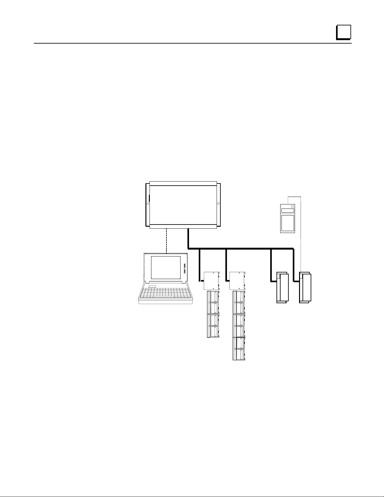
Series 90-70 PLC connected to a Genius bus with I/O blocks and two Field Control stations.
Series 90-70 PLC
1
The Host CPU
The Genius Bus Inter face Unit is ideally suited for use with a Series 90-70 or Series 90-30 PLC.
However, any type of PLC or computer capabl e of c ontrolling a Genius bus can be us ed as the host .
Possible hosts in cl ud e Seri es Six PLCs, Seri es Fi ve PLCs, an d comput ers equip p ed with a PCIM
(Personal Computer Interface Module), QBIM (Q-Bus Interface Module), or a third-party GENIbased interfa ce modul e, in cluding several in DCS systems.
Hand-held
Monitor
Genius Bus
GFK-0825F Chapter 1 Introduction 1-7
Page 17

1
PCIM
A More Complex Field Control and Genius System
A more complex communications and control system is illustrated below. In this system, the Field
Control stations and Genius blocks on the lower left are controlled by a Series 90-70 PLC. The
Field Control stations and Gen i us blocks on the lower right are controlled by a host computer
equipped with a PCIM (Personal Computer Interface Module).
The PLC communicat es with a computer runn ing programming softwar e via an SNP (Serial
Network Protocol) link. And the PLC, host computer, and programmer computer exchange system
data vi a an Ethernet com munications link.
Series 90-70 PLC
SNP
Ethernet
Genius Bus
Genius Bus
For more information about Genius systems and communications, please refer to:
The
Genius I/O System and Communications User's Manual
operation, and communications formats.
, which describes Genius system
The
Bus Controller User's Manual
for the system host, wh ich inclu d es s p ecific system interfa ce
instructions.
1-8 Field Control™ Genius® Bus Interface Unit User’s Manual – October 1999 GFK-0825F
Page 18

Required Genius and Host System Equipment
The following system equipment is required:
Genius Hand-held Monit or version 4.6 (IC660HHM501J) or later.
For a Series 90-70 PLC
Series 90-70 CPU firmware, release 3.0 or later.
A Series 90-70 Genius Bus Contr oller, release 3.0 or later. The Bus Controller must be 4.0
or later for full diagnostics display from Logicmaster 90-70, or for redundancy
applications.
If Logicmaster 90-70 programming and configuration software is used, it must be
release 3.0 or later:
.
A
B
For a Series 90 30 PLC
Series 90 30 CPU firmware: any version.
Logicmaster 90-30 programming and configuration software: any version.
Series 90-30 Genius Bus Controller: any ver sion.
IC641SWP701F (3.5", 2DD, 5.25" 2S/HD)
.
IC641SWP704C (5.25" 2S/2D)
1
For a Series Six™ PLC
CPU: rev. 105 or later.
Logicmaster 6 Programming Software: release 4.02 or later.
Bus Controllers: IC660CBB902 or 903, version 1.7 or later.
For a Series Five™ PLC
CPU: rev. 3.2 (catalog number with E suffix) or later.
Logicmaster 5 Programming Software: release 2.01 or later.
Bus Controller: any version
For a Host Computer
PCIM: any version
QBIM: any version
GFK-0825F Chapter 1 I ntroduction 1- 9
Page 19
1
Using Field Control in a CPU Redund ancy System
Most systems use only one Bus Controller and CPU to control the I/O on the Genius bus. CPU
redundancy, which can be used for backup CPU/Bus Controller protection in critical applications,
is described in detail in the Genius documentation. The section that follows here summarizes how
Field Control product s can fit into a Genius CPU Redun dancy system.
CPU/Bus Controller Redundancy: Overview
In CPU redundancy, two Bus Controllers on the same bus can send control outputs at the same
time. Both Bus Controllers automatically receive i nputs an d fa u lt repor t s from all devi ces on the
bus that have been configured as being in “CPU Redundancy” mode. The Bus Controllers must
use serial bus addresses (devic e numbers) 30 and 31.
Field Control stations can be used on a bus controlled by redundant CPUs/Bus Controllers.
Bus
Controller
(Device 30)
How the two sets of outputs from the dual CPUs are handled by a Bus Interface Unit depen ds on
whether the Bus Interface Unit is set up for Hot Standby or Dupl ex redundancy.
contains any analog modules, the only form of CPU redundancy permitted is Hot Standby.
Bus
Controller
(Device 31)
If the station
46471
Hot Standby CPU Redundancy
A Bus Interface Unit con figured for Hot Stan dby mode is normally controlled by the Bus
Controller assigned to serial bus address 31. If no outputs are available from 31 for three bus
scan s, the Bus Inter face Unit accep ts outpu ts from the Bus Contr oller assigned to serial bus address
30. If outputs are not available fr om either Bus Controller, outputs go to th eir configur ed defaults
or hold their last state. In Hot Standby redundancy, Bus Controller -31 always has priority; when it
is on-line, it has control of the outputs.
Duplex CPU Redundancy
A Bus Int er face Unit configur ed for D u p lex mode compares outp uts it recei ve s from the two Bu s
Controllers, to determin e if they match. If corresponding outputs are th e same, th e Bus Interface
Unit set s the output to that state. If corres p onding outputs are not the same, the Bus Int erface Unit
sets the output to its config ur ed ON or OFF Duplex Default Stat e. If either Bus Controller stops
sending outputs to a Bus Interface Unit, its outputs are directly controlled by the r emaining Bus
Controller.
mode if the station contains any analog I/O modules.
1-10 Field Control™ Genius® Bus Interface Unit User’s Manual – October 1999 GFK-0825F
Only discret e I/O modules can operate in Duple x redundancy mode; do not use Duplex
Page 20
Using Field Control in a Genius Bus Redundancy System
In Geni u s bu s r edundancy, there ar e two bus cables ea ch connected to a Bus C ontroller. I/O
devices may be connected to either one bus of the pair, or to both. However, a device that is
connected to both busses actually communicates on only one bus at a time. Before the alternate
bus can be used for communication s, a bus switchover must occur and th e device must “log in”
with the Bus Controller (s) on the alternate bus.
The Bus Interface Unit Terminal Block contains a built-in bus switching r elay that is used to switch
busses in a dual bus system. Other types of devices with this capability ar e dedicated Bus
Switching Modules and Series 90-70 Remote I/O Scanner modul es. These are the only types of
devices that can be directl y connect ed to both redundant bus ca bl es .
A Bus Int er face Unit can not be used a s the BSM Contr ol ler for a bus stub. Other devices cannot be
located on a stub downstream of a BIU.
Also, the Bus Interface Unit should n ot be con nected to an externa l Bu s S wi t ching Mod u le.
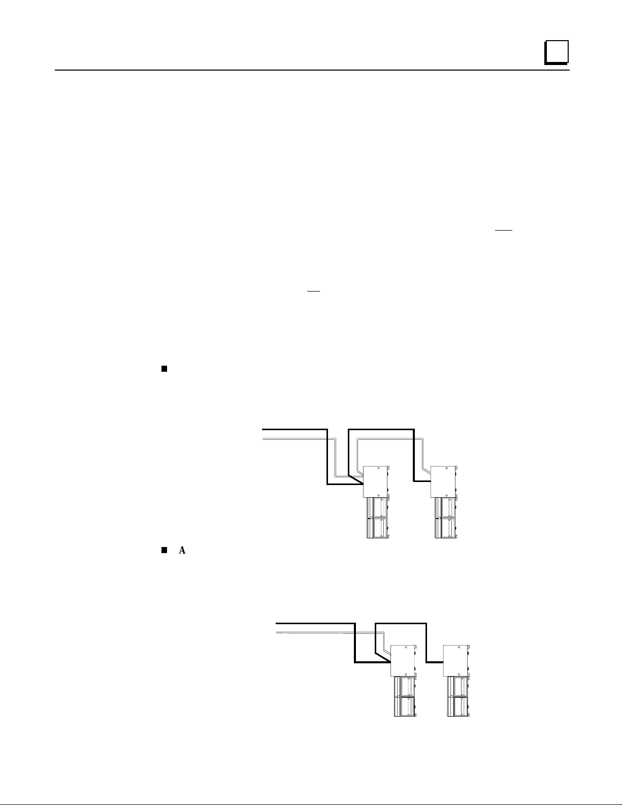
Redundant Bus Configurations
Many different redundant bus configurations are possible. T hree basic ways of using a Bus
Interface Unit wi th a r edundant bu s are descr i bed below.
1
A Bus Interface Unit can be installe d directly on both cables of the dual bus pair. The
Bus Interface Unit is configured to operate as a bus switching device in addition to perfor ming
its nor mal functions. Here, two Field Control stations ar e installed on a dual bus. Each Bus
Interface Unit would be set up as a bus switching devi ce.
Bus A
Bus B
A Bus Interface Unit can be located on just one bus of a redundant bus pair, i f bus
46472
redundancy is n ot needed for the modules in th at station . In this exam ple, the Bus Interface
Unit on th e left is connected to both Bus A and Bus B an d is configur ed as a bus swi tching
device. The Bus Interface Unit on the right, which serves non-critical I/O modules, is
conn ected to Bus A only, and is n ot configur ed as a bus switching device.
Bus A
Bus B
46473
GFK-0825F Chapter 1 I ntroduction 1-11
Page 21
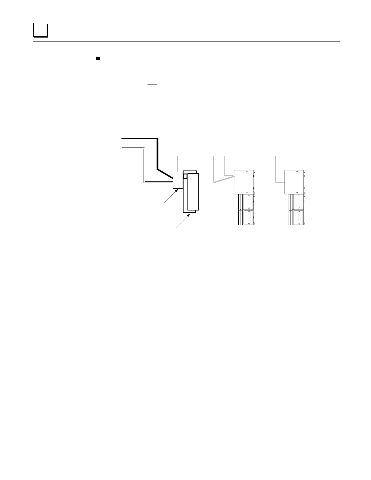
1
A Bus Interface Unit can be located on a bus stub.
A Bus Interface Unit can also be located
on a bus stub, which is a short length of unterminated cable downstream of either a Genius I/O
block/Bus Switching Module combination, or a Remote I/O Scanner connected to a dual bus.
Because the bus stub cable itself is not r edundant, this type of installation does not provide as
much protection as conn ecting directly to a dual bus. The bus switching device to which the
bus stub i s connected can be another Geni u s block wi th a Bus Swi tching Module atta ched, as
shown below, or a Series 90-70 Remote I/O Scanner.
In thi s ex ample, th er e are two Field Contr ol stations install ed on a bus stu b. Each is
configu red as “BSM Presen t” but not con fi g ured as a “BSM Controll er ”.
Bus A
Bus B
Bus
Switching
Module
Genius Block
Acting as a
BSM Controller
Up to 7 Additional Devices on the Bus Stub
46474
Up to seven device s (not counting th e BS M /block or Re mote I /O Sca nner to which the dua l bus is
connected) can be installed on a bus stub. Each device on a bus stub counts towar d the total of 32
devices on the Geniu s bus.
Restric tions on the number and length of bus st ubs that may be used on a dual bu s a re exp lained in
the
Genius I/O System and Communications User's Manual.
1-12 Field Control™ Genius® Bus Interface Unit User’s Manual – October 1999 GFK-0825F
Page 22
Chapter
2
Description
This chapter descr ibes:
Genius Bus Interface Unit
Bus Interface Unit Power Su pply
Bus Interface Unit Terminal Block
Specification s
Genius Bus Inter face Unit
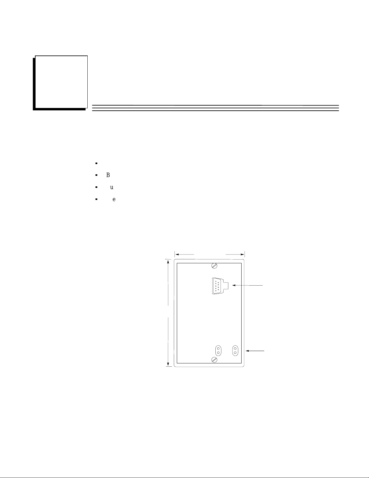
The Genius Bus Interface Unit is a small, rugged, intelligent module with a sturdy aluminum
housing. The module has four status LEDs, described below, and a connector for attaching a
Genius Hand-held Monitor.
3.25" (8.2mm)
HHM
Connector
5.0" (12.7mm)
LEDs
The Bus Interface Unit contains th e logic power s u p pl y n eed ed to opera te the I/O modules
connected to it. It mounts on a separate terminal block, to wh ich it and all bus wiring are attached.
The configuration is stored in non-volatile memory located in the terminal block. Both the power
supply and terminal block a re described in this chapter.
The Bus Interface Unit has a replaceable 1A, 5x20mm 250VAC slow-blow fuse on the input power
lines. The fuse can be changed without disturbing the wiring of any other modules (instructions are
in chapter 3).
GFK-0825F 2-1
Page 23
2
LEDs
The LEDs on the Bus Interface Unit show its operating status.
BUS B PWR
RUN OK
ACTIVE
PWR
OK
lights to indicate that +5V power is available for logic oper ation.
lights to indicate that the module has passed its powerup diagnostic tests.
See the table below for more information.
RUN
lights only if output modules ar e in the BIU configuration and are written
to by the controlling bus controller . See the table below.
BUS B
if the Bus Interface Unit is installed on a dual (redundant) bus, this LED
lights if Bus B is the currently-active bus.
OK RUN Meaning
ON ON Module functioning, CPU communicating
ON OFF Modul e functioning, no CPU communications f or 3 bus scans
ON Blinking Module functioning, circuit forced
Blinking ON Circuit fault, CPU com m unic ati ng
Blinking OFF Circuit fault, no CPU communications for 3 bus scans
Alternate Bli nki ng Circuit fault, Circ ui t forced
Synchronous Blinki ng No CPU communications - block number conflic t
OFF Blinking Electronics/Terminal Assembly mismatch
OFF OFF No block power, or Block faulty
2-2 Field Control™ Genius® Bus Interface Unit User’s Manual – October 1999 GFK-0825F
Page 24

Bus Interface Unit Power Supply
The power supply in the Bus Interface Unit provides power for the Bus Interface Unit itself an d
logic power for all I/O modules that may potentially be installed at that station. External power
must be supplied for field wiring of input and output devices.
The power supply is not da maged by either of t he following:
Reversing input voltage on terminals 1 and 2.
Timing
Temporary
The Bus Interface Unit provides power to all I/O modules that are installed at the station. I/O
module operation is governed by a System Reset sign al to ensur e controlled operation during the
power up and sh ut down processes. As sh own in the timing diagram below, momentary power
losses of less than 10 mS (for 24VDC BIU) or 20mS (for 115VAC/125VDC BIU) do not affect I/O
module operation. Longer power losses generate a Reset for all system I/O modules.
overcurrent conditions on the 6.5 VDC output.
2
24VDC
Nominal
or 115 VAC
Nominal
6.5V Output
Input Power
On
RST*
Voltage
Overshoot
5% (max)
200mS
(min)
95% (min)
Minimum:
10mS for 24VDC BIU
20mS for 115VAC/12 5V DC BIU
Momentar y
Power
Loss
Hold
Up
Time
3mS
(min)
Voltage
Overshoot
5% (max)
200mS
(min)
Input Power
Off
Hold
Up
Time
10mS
(min)
3mS
(min)
GFK-0825F Chapter 2 Description 2-3
Page 25
2
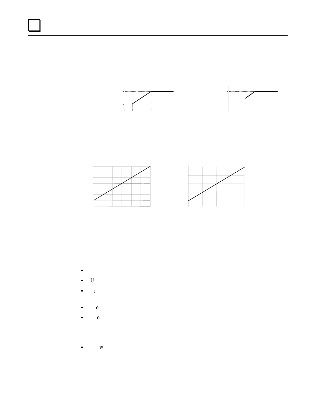
Backplane Current
With a DC input voltage, the amount of current available to the backplane may be limited by lower
input voltage as indicated below.
Backplane
Current
Available
(Amps)
Calculating Input Power Requirements for a Bus Interface Unit
The charts below show typical input power requirements for a Bus Inter face Unit.
For 24VDC Bus Interface Unit
15.9
14.1
Typical
12.3
Input
10.0
Power
(Watts)
7.7
5.5
3.4
0.25 0.50 0.75 1.0 0 1.20 1.400
Total Backplane Cu r rent (Amps)
For 24VDC Supply
1.4
1.2
1.0
18
19
Voltage In
21
Typical
Input
Power
(Watts)
for DC
Inputs
For 125VDC Supply
Backplane
Current
Available
(Amps)
2.0
1.8
For 115VAC/125VDC Bus Interface Unit
24.0
18.75
13.5
8.25
3.0
0
0.50 1.501.00 2.0
Total Backplane Cu r rent (Volts)
105
110
Voltage In
48.0
37.75
27.5
17.25
7.0
Typical
Input
Power
(Volt/Amps)
for AC
Inputs
Note
For a 24VDC Bus Interface Unit, start-up surge at full load is 15-50 Amps for 3
milliseconds (maximum). For a 115VAC/125VDC Bus Interface Unit, startup
surge at full load is 20 Amps peak for 3mS.
To deter m ine speci fi c system requirem en ts:
Determine total output load from typical specifications listed for individual modules.
Use the appropriate graph of input power a bove to determine avera ge input power.
Divide the input power by the operating source voltage to determine the input curr ent
requirements.
Use the lowest input voltage to determine the maximum input current.
Allow for s t artup sur g e cur rent requirem en ts. Startu p surge curr ent levels are a function of
source impedance an d, therefore, are installation-dependent. Startup surge currents can vary
for approximately 3mS. For th e 24VDC Bus Interface Unit, variance is between 25A and 50A.
For the 115VAC/125VDC Bus Interface Un i t, startup surge current is 20A maximum peak.
Allow margins (10% to 20%) for variations.
2-4 Field Control™ Genius® Bus Interface Unit User’s Manual – October 1999 GFK-0825F
Page 26

Bus Interface Unit Power Dissipation
The Bus Interface Unit power dissip ation can be determined once th e ba ck p lane curr en t supplied to
the I/O modules is known.
The following equation can be used to calculate BIU power dissipation:
BIU Power Dissipat ion = Input P ower - (t otal back plane c ur r ent x 6.5 volts)
For exa mp le:
A. Total backplane cur rent = 0.5 Am ps
B. Typical Input power = 7.7 Watts
Therefore:
BIU Power Dissipat ion = 7.7 W - ( 0.5 x 6.5 ) = 4.45 Watts
2
GFK-0825F Chapter 2 Description 2-5
Page 27

2
Load Requirements for Hardware Components
The tabl e bel ow shows the DC load r eq u ired by each module an d har dware component. All r atings
are in milliamps. Input and Output module current ratings are with all inputs or outputs on. These
are maximum requirements, not typical.
Catalog Number Description Current (mAmps)
IC670MDD441 Mixed I/ O Module, 24 VDC 10 Inputs, 6 Outputs 110
IC670MDL233 Input Module, 120 VAC 8 Isolated Points 40
IC670MDL240 Input Module, 120 VAC 16 Grouped Points 77
IC670MDL241 Input Module, 16 Points, 2 groups 240 VAC 77
IC670MDL640 Input Module, 24 VDC 16 Grouped Pos/Neg Points 83
IC670MDL641 Input Module, 48 VDC 16 Grouped Pos/Neg Points 83
IC670MDL642 Input Module, 125 VDC 16 Grouped Pos/Neg Points 77
IC670MDL643 Input Module, 5/ 12 VDC 16 Point 80
IC670MDL644 Input Module, 12/24 VDC 16 Grouped Pos/Neg Fast Inputs 80
IC670MDL730 Output Module, 8 Pt 24 VDC Elect ronic Short Circuit Protection 125
IC670MDL740 Output Module, 12/24 VDC 0.5 Amp, 16 Grouped Pos. 111
IC670MDL742 Output Module, 5/12/24 VDC Negative Outputs 111
IC670MDL330 Output Module, 16 Point 12-120 VAC 16 Pt 1.0 Amp 285
IC670MDL331 Output Module, 120 VAC 2 Amp, 8 Isolated Points 154
IC670MDL930 Relay Output Module, 2 Amp, 6 Form A Points and 2 Isolated
Form C Points
IC670ALG230 Analog Current Input Module, 8 Grouped Points 51
IC670ALG240 Analog Input Module, 16 point Grouped 251
IC670ALG281 Analog Voltage Input Module, 8 Grouped Points 150
IC670ALG282 Analog Voltage Input Module, 16Grouped Points 150
HE670ACC100 Input Simulator Module, Horner 100
HE670ADC810 Analog Input Module, Horner, +/-10VDC, 0-10 VDC 131
IC670ALG620 RTD Input Module 190
IC670ALG630 Therm ocouple Input Module 195
IC670ALG320 Analog Current/Voltage Output M odul e, 4 Grp Points 51
IC670ALG330 Analog Current source Output Module, 8 Points 85
IC670MFP100 Micro Field Processor 111
IC693PRG300 Hand-held P rogram m er 170
313
IC660HHM501 Genius Hand-held Monitor 0
Hand-held Monitor and Hand-held Programmer
The Genius Hand-held Monitor (IC660HHM501), used for configuring and monitoring the BIU,
has it s own ba ttery and does not add to the load on the BI U.
However, if a Han d-held Programmer (IC693PRG300) will be attached to a Micro Field Processor
or other module in the I/O Station, it must be con sidered as a load component as listed above.
2-6 Field Control™ Genius® Bus Interface Unit User’s Manual – October 1999 GFK-0825F
Page 28

Hot Insertion/Removal of Modules
Bus Interface Un i ts IC670GBI002(F) and IC670GBI102A or later support Hot Insertion/Removal
of modules in the I/O Station.
Hot Insertion/Removal means that modules can be removed and replaced while I/O Station power
is applied without affecting the BIU or other modules in the I/O Station. Separate I/O module
power must be switched off to the module being inserted or removed.
Hot Insertion/Removal requires the use of specific modules and I/O terminal blocks:
• I/O modules having catalog num ber suffix J or above. These modules have a projecting
alignment tab that fits into a corresponding alignment tab on I/O Terminal Blocks listed below.
Note that modules with this tab can also be installed on older I/O Terminal Blocks that do not
have mating alignment tabs. However, Hot Insertion/Removal are not suppor t ed in such an
installation.
• I/O Term inal Blocks IC670CHS101, 102, or 103. These I/O Terminal Blocks have pr ojecting
alignment tabs designed to facilitate Hot Insertion/Removal of modules. Modules that are
earlier than r evi sion J cannot be mount ed on these ter minal blocks .
I/O Terminal Blocks IC670CHS001, 002, and 003, which lack alignment tabs, do not support
Hot Insertion/Removal of modules. With th ese terminal blocks, I/O Station power should be
off when installing or r emoving modules.
2
Mixing IC670CHS10x terminal blocks with IC670CHS00x terminal blocks in the same I/O
statio n is no t recommended.
Faults Reported During Hot Insertion/Removal
When using the recommended equipment listed above, Hot Insertion/Removal will cause the
expected fault reports r elated to the loss of or addition of the module and its I/O circuits. These
faults should be cleared in the normal manner. However, Hot Insertion/Removal of a r ev. J or later
module will NOT cause Configuration Mismatch errors that in some types of systems can sh ut
down the controller.
I/O Module Data During Hot Insertion/Removal
As men tioned, separate I/O module power must be turned off for Hot Insertion/Removal. When th e
module is installed and power is r eapplied, module data will quickly return to normal. For
intelligent I/O modules, there m a y be a delay of a few seconds while the m odule goes through its
powerup sequence.
Hot Insertion/Removal for a Micro Field Processor
A Micr o Field Processor that is r evision J or later may be removed/inserted as described above.
Note, however, that although the Micro Field Processor will start functioning upon reinstallation,
the MFP's applica ti on pr ogram must be rel oa ded . I/O data controlled by the Micr o Fiel d Processor
will be incorrect until that has been don e. (The BIU configuration of the Micro Field Processor is
not affected by Hot Insertion/Removal).
Hot Insertion/Removal Not Permitted in Hazardous Locations
In hazardous locations, I/O Station power must be turned off before inserting/removing module.
Failure to observe this precaution may result in personal injury, system malfunction and/or damage
to the eq u ipment.
GFK-0825F Chapter 2 Description 2-7
Page 29
2
Bus Interface Unit Terminal Block
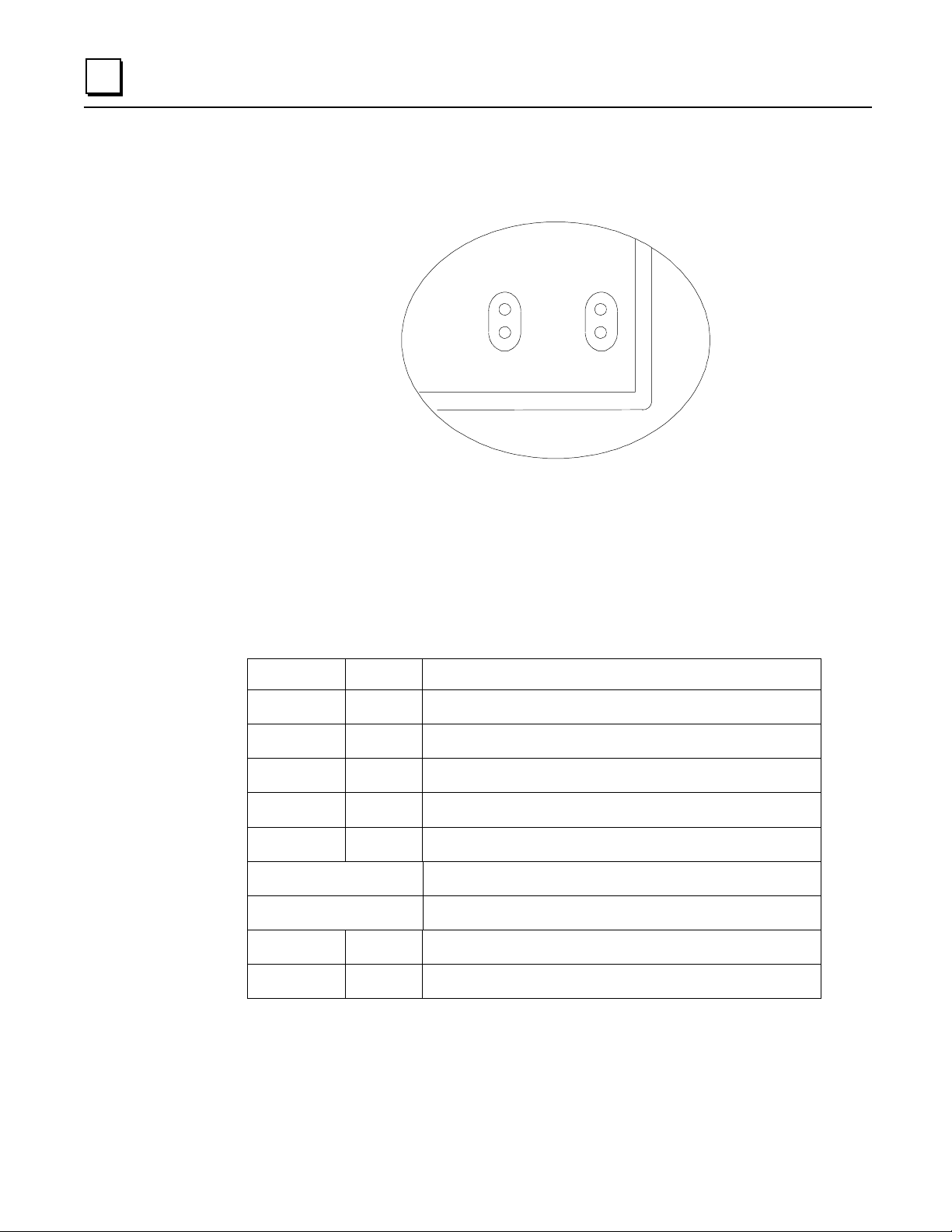
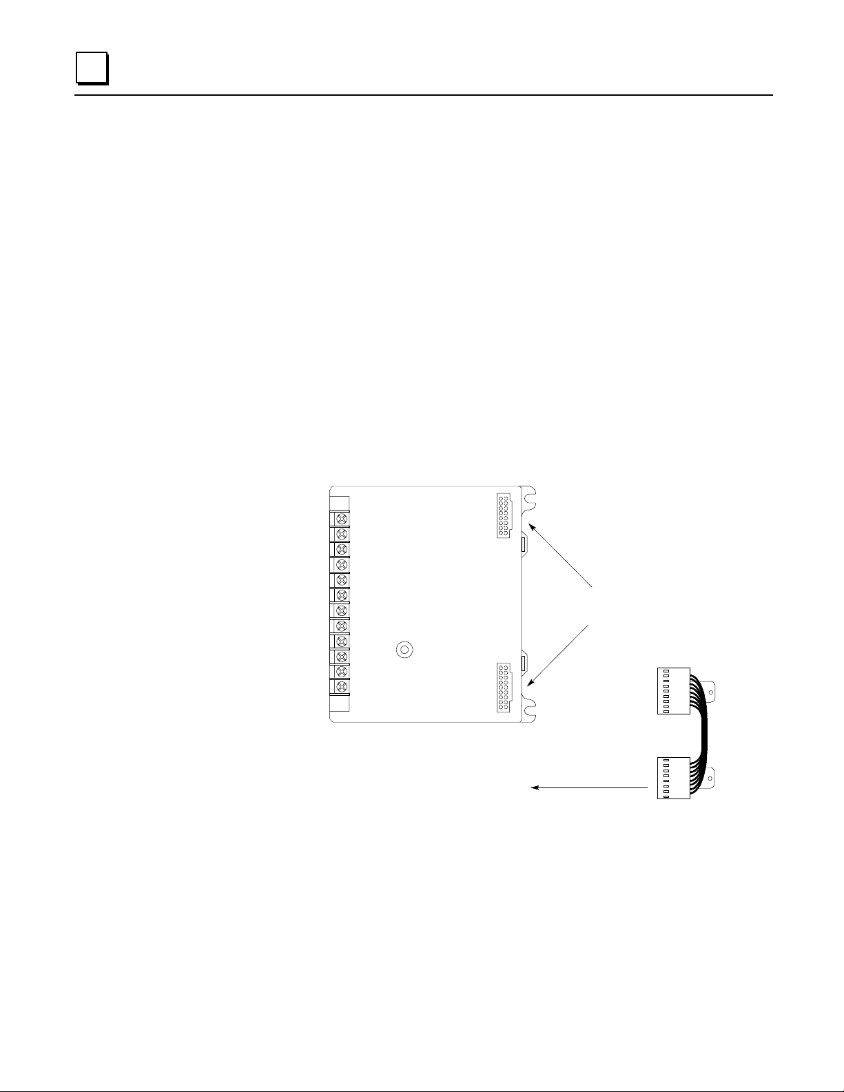
The Bus Interface Unit provides terminals for power and ground conn ections. Maximum wir e size
is AWG #14. (avg 2.0690mm2 cross-section).
The Bus Inter face Unit Terminal Block also has eight input terminals for connection to a single or
dual Genius bus. Th ese terminals accom modate up to two AWG #14 wires. The Bus Interface Unit
Terminal Block contains bus-switching circuitry per mitting it to be used
dual bus redundancy system.
A connect ing cable is provided wi th each I/ O Ter minal Block. It is used to connect th e Bus
Interface Unit Terminal Block t o the first I/O Terminal Block. The same type of cable
inter con nects su bseq uent I/O Terminal Blocks. The cable has molded connector s th at are keyed t o
assure prope r o rientation.
The Bus Interface Unit Terminal Block is designed to be extremely r eliable; it should not be
necessary to replace or rewire it after installation.
The Bus Interface Unit Terminal Block stores the configuration parameters for the station. The Bus
Interface Unit can be removed without removing the wiring or recon figuring the station.
as a BSM Controller
in a
Terminals for
power and
communications
wiring
I/O Terminal Block
Connectors
to next terminal block
46457
Connecting
Cable
2-8 Field Control™ Genius® Bus Interface Unit User’s Manual – October 1999 GFK-0825F
Page 30

Functi on a l Sp eci fi cations
Bus Interface Unit:
Reliability More than 183,000 hours operation MTBF, calculated
24VDC Power Supply Input
Nominal Rated Volt age 24 VDC
Voltage Range 18 VDC to 30 VDC
Power 16.8 Watts maximum at full load (nominal volt age)
Inrush Current 15-50 Amps peak, 3 mS maximum. Inrush current is installation
Power Supply Output
to I/O modules:
Holdup Time 10mS maximum from nominal input voltage.
115VAC/125VDC Power Supply Input
Nominal Rated Voltage 115 VAC, 125 VDC
Voltage Range 90 to 135 VAC, 105 to 150 VDC
Frequency (AC) 47 to 63 Hz
Power 115 VAC: 48VA maximum at full load (nominal volt age)
Inrush Current 20 Amps peak, 3 mS maximum.
Power Supply Output
to I/O modules:
Holdup Time 20mS maximum from nominal input voltage.
2
dependent. See page 2-4.
6.5 VDC ±5%
1.4 Amp maximum. See page 2-4.
125 VAC: 24W maximum at full load (nominal voltage)
6.5 VDC ±5%
2 Amp maximum. See page 2-4.
Bus Interface Unit Terminal Block:
Power Requirements 16mA maximum
Reliability More than 600,000 hours operation MTBF, calculated
For power requir ements of specific I/O modules, please see the
Manual
GFK-0825F Chapter 2 Description 2-9
, (GFK-0826).
Field Control I/ O Modules User's
Page 31

Chapter
3
Installation
This chapter descr ibes:
System Wi r ing Guid elines
System Grounding
Locations for Field Con trol Modules
Installing the Bus Interface Unit Terminal Block on a Panel
Installing the Bus Interface Unit Terminal Block on a DIN Rail
Installing the Cables Between Terminal Blocks
Power Wiring to the Bus Interface Unit
Connecting the Communications Bus
Installing/Removing the Bus Interface Unit
Removin g/Rep lacing the Bus Interface Unit Fuse
Upgrading the BIU firmware.
For more information, please refer to:
The Field Control I/O Modules User's Manual for information about in stalling I/O modules.
Appendix C, “The Genius Serial Bus” for a detailed description of the ch aracteristics of the Genius
bus.
GFK-0825F 3-1
Page 32

3
Preinstallation Check
Carefully inspect all shipping containers for damage during shipping. If any part of the system is
damaged, notify the carrier im mediately. The damaged sh ipping container should be saved as
eviden ce f or insp ection by the carrier .
As the consign ee, it is your res p onsibility to register a clai m wi th the carr ier for damage incurred
during shipment. However, GE Fanuc will fully cooper a t e with you, should such action be
necessary.
After unpacking the Field Control modules and other equipm ent, record all serial n umbers. Serial
numbers are required if you sh ould need to contact Product Service during the warranty period of
the equ ipment.
All shipping containers and all packing material sh ould be saved should it be necessary to transport
or shi p an y par t of the system.
Static Protection
The Bus Interface Unit ha s CMOS component s that ar e suscept i ble t o static dam age.
static handling techniques whe n handling this module.
Hand-held Monitor Connector
The connector on the Genius Bus Interface Unit is intended for use with a Genius Hand-held
Monitor only. It must be connected to a nonincendive circuit only.
Use proper
HHM (must be connected to
a nonincendive circuit only)
3-2 Field Control™ Genius® Bus Interface Unit User’s Manual – October 1999 GFK-0825F
Page 33

System Wiring Guidelines
Four types of wiring may be encountered in a typical factory installation:
1. Power wiring - the plant power distribution, and high power loads such as high
horsepower motors. These circuits may be rated from tens to thousands of KVA at 220
VAC or higher.
2. Control wiring - usually either low voltage DC or 120 VAC of limited energy rating.
Examples are wiring to start/stop switches, contactor coils, and machine limit switch es.
This is generally the interface level of the Genius discrete I/O.
3. Analog wiring - transducer outputs and analog con trol voltages. This is the in terface level
to Genius I/O ana log blocks.
4. Commun ications and signal wiring - the communications n etwork that ties everything
together, including computer LANs, MAP, and Geni us I/ O and commun ication s bus.
These four types of wiring should be sepa rat ed as much as possible to reduce the hazards from
insulation failure, miswiring, and interaction (noise) between signals. A typical PLC system with
Genius I/O may require some mixing of the latter three types of wiring, particularly in cramped
areas inside motor contr ol centers and on contr ol panels. In g en er al, it is accep table t o mi x the
communications bus cable with the I/O wiring from the blocks, as well as associated control level
wiring. All noise pickup is cumulative, depending on bot h the spacing between wires, and the
dist ance span th ey run together. I/O wires and comm unications bus cabl e can be placed random ly
in a wiring trough for lengths of up to 50 feet . If wiring is cord-tied (harnessed), do not include the
bus cable i n the harn es s, s ince bin ding wires tightly together increas es the coupling and mech an ical
stress that can damage th e relati vely soft insulation of some serial cable t ypes.
3
Wiring which is external to equipment, and in cable trays, should be separated following NEC
practices.
Installing Additional Suppression
It is possible some i nstall ations mi ght exceed the surge imm unity capa bilities specified in ch apter
1. This i s most likely in ou tdoor installations or where the powe r sou rce is from another bu ilding or
gr ound system. It is prud e nt to provide local transient prote c tion.
Appendix B describes installation of additional suppression at the power and communications
lines.
GFK-0825F Chapter 3 I nstallation 3-3
Page 34

3
System Grounding
All compone nts o f a control syste m and t he devices it contro ls must be properly
grounded.
central earth ground point as shown bel ow. This ensures that no ground conductor carries current
from any ot her bran ch.
Ground condu ct ors should be connected in a star fashion, with all bran ch es r ou t ed to a
Programming
Device
Each Terminal
Block
Motor Drives and
Other Electrical
Control
Equipment
Machinery
Earth
Ground
Central
Ground Point
connections not shown
NOTE
Signal and power
Each Field Control Terminal Block has a chassis ground terminal for safety and noise protection .
This terminal should be con n ected to th e conductive mounting panel with a 4-inch maximum
length of A W G #14 (avg 2. 1mm2) wire. Use ha rd wa re such as star washers t o ensur e ground
integrity.
The con trol panel and enclosu re shoul d al s o be bonded to the plant system ground per code.
Inadequate gr ounding may compromise system integrity in the presen ce of power switching
transients and surges.
3-4 Field Control™ Genius® Bus Interface Unit User’s Manual – October 1999 GFK-0825F
Page 35

Locations for Field Control
Field Control terminal blocks must be installed on a 35mm x 7.5mm DIN rail. Modules can be
loca ted on equipm ent, in junc tion box e s , insid e pa nel s , be hind operator stations, in NEMA
enclosures as little as 4" deep, and in other locations where space is limited. The area should be
clean an d free of airborne con taminants, with ad eq uate cooling air fl ow.
Modules can be mounted in any orientation without derating the temperature specification. They
can be installed in a linear stack as shown on the left in the following illustration, using the short
connection cables provided with each I/O Ter minal Block. An optional 21-inch (0.53 meter) cable
(IC670CBL002) is al so available. Only one 21" cable can be used per Field Control station.
All of the I/O Terminal Blocks in a group must be connected either at the top or the bottom of the
Bus Interface Unit (BIU in the illustration). A Bus Interface Unit may not be connected between
I/O Terminal Blocks.
BIU
3
46405
Install ing th e DI N Rai l
BIU
BIU
BIU
All Field Control Terminal Blocks must be mounted on a 7.5mm x 35mm DIN ra il. The rail must
have a conductive (unpainted) finish for proper grounding.
For best vibration resistance, the DIN rail sh ould be in stalled on a panel using screws spaced
approximately 6 inches (5.24cm) apart. When using multiple rail sections, be sure they are properly
aligned.
GFK-0825F Chapter 3 I nstallation 3-5
Page 36

3
Clamp
Screw
5.90in
4.25in
4.50in
5.00in
Wireway
4.31in
1.75in
Mount the DIN rail at least 4. 25 inches (10.80 cm) from any wireway or other obstruction
wiring side of the Bus Interface Unit.
Allow more space if th e wiring for I/O modules is very stiff.
on the
A wiring template is also provided in the instruction sheet included with each Bus Interface Unit
terminal block.
Drill mounting holes for the BIU Terminal Block as shown below. Allow a small tolerance
between the top and bottom of adjacent termin al blocks. After mounting the terminal blocks on the
DIN rail as descri bed on the followi ng pages, use #6 screws (not supplied) to attach them to the
panel. Length for all screws is 3/8 inch (9.525mm).
14.99cm
11.43cm
4.45cm
3-6 Field Control™ Genius® Bus Interface Unit User’s Manual – October 1999 GFK-0825F
10.95cm
12.70cm
Page 37

Installing the Bus Interface Unit Terminal Block on the DIN Rail
1. Tilt the Bus Interface Unit Terminal Block and position it over the rail, as shown below left,
catching the rail behind the tabs in the terminal block.
2. Pivot the terminal bl ock downward until the spring-loaded DIN rail latches in the ter minal
block click into place.
12
DIN
tabs
3. Tighten the DIN rail clamp screw (see below left). Recommended torque is 4 to 6-in/lbs.
rail
3
Installing the BIU
Terminal Block
Tighten Loosen
Removing the BIU
Terminal Block
Removing the Bus Interface Uni t Term inal Block from the DIN Rail
1. Loosen the clamp scr ew.
Pry
Upper
latch
Pry
Lower
latch
2. Insert a small flat-blade screwdriver into the upper latch and pry it out ward. Then, pull up gen t ly
on the top of the terminal block to disengage the upper latch from the rail.
3. Keep gently pulling the top of the terminal bl ock away from the rail. Insert the screwdriver
into the lower latch and pry it outward to free the terminal block.
GFK-0825F Chapter 3 I nstallation 3-7
Page 38

3
Installing the Cables Between Terminal Blocks
Before instal ling modules on their terminal blocks, install th e con necting cable(s) bet w een terminal
blocks. A short connectin g ca bl e, as illustrated bel ow, is su p pl ied with ea ch I/O Termin al Block. A
set of three connecting cables is available as renewal part number IC670CBL001. Optional 21-inch
(0.53 meter) cabl e is also available (IC670CBL002) (only one 21" cable can be used per Field
Control station).
The illustration below shows cable connection between a Bus Interface Unit terminal block and an
I/O Terminal Block. Make connections between I/O Termina l Blocks in the same manner. The
conn ectors are k eyed to assur e proper in s tallati on .
Bus Interface
Unit Terminal
Block
I/O Term in a l
Block
Connector for Cable
to Next Device
After installing the cable, be sure it is firmly seated on both connectors.
Terminal
Block
Connection
Cable
3-8 Field Control™ Genius® Bus Interface Unit User’s Manual – October 1999 GFK-0825F
Page 39

Powe r Wiring to the Bus Interface Unit
Note: Do not apply power until the BIU module is in stalled on the Terminal Block.
1. Connect an appropriate power source as shown below.
3
Low Voltage
Connections
(IC670GBI002)
High Voltage
Connections
(IC670GBII02)
-
24 VDC
+
For BIU version IC670GBI102, if a DC supply is used the polarity is not important.
BIU version IC670GBI102 provides intern al overvoltage protection. Terminal 4 is normally
connected to frame groun d (terminal 3) by a factory-installed jumper. If overvoltage
protection is not required or is supplied upstream this feature can be disabled by removing the
jumper , leaving pin 4 unconnected.
2. Use one AWG #14 (2. 1mm2) or two AWG #16 (1. 3mm2) wires per t er minal. The wires into a
terminal should be the same type and size. Wires must be copper con ductors rated for
75 degrees C (167 degrees F) only. Suggested torque for the terminal screws is 9 in/l bs.
3. Connect the ground terminal to the conductive mounting panel with a 4-inch maximum length
of AWG #14 (a vg 2.1mm2) or larger wire. Use hardware such as star washers to ensure ground
integrity.
115VAC or
125VDC
GFK-0825F Chapter 3 I nstallation 3-9
Page 40

3
Connecting the Communications Bus
The Bus Interface Unit Terminal Block has a two sets of bus terminals. The terminals in the center
port ion of the ter min al block are for the main bus cable; they are always used.
The outermost set of bus te rminals is for an optiona l red undant (du al) bu s c able. The Bus Interface
Unit Terminal Block has built-in bus switching capability;
a dual bus application
.
do not attach a Bus Switching Module in
46462
Termin als accept one AWG #14 (2 .1mm2) or two AWG #14 (avg 2.1mm2 cross section) copper
75 deg. C
terminal should be the same t ype. The suggested torque is 9 in/lbs (1 Nm).
Bus Cables
Bus connections can be made using stan dard bus cables (cable specifications for the Genius bus are
detailed in Appendix C. Also see Appendix C for a discussion of the characteristics of the Genius
bus.
When making bus connections, the maximum exposed length of unshielded wires should be two inches
(5cm). For added protection, each shield drain wire should be insulated with spaghetti tubing to prevent
the Shield In and Shield Out wires from touching each other, or the signal wir es.
For applications using 150 ohm cables, prefabricated cables are availabl e in 15" (IC660BLC001)
and 36" (IC660BLC003) lengths. These cables terminate in mating connectors that simplify wiring
between I/O blocks. The 36" cable is recommended for Field Control installations.
Redundant Bus
Connections
(optional)
Main Bus
Connections
(167 deg. F) wires. Each ter minal can accept sol id or stranded wires . The wires on any
Serial 1
Serial 2
Shield In
Shield Out
Shield Out
Shield In
Serial 2
Serial 1
B1
B2
Bin
Bout
Aout
Ain
A2
A1
SHD
SHDINSER2SER
OUT
1
SHD
SHDINSER2SER
OUT
1
3-10 Field Control™ Genius® Bus Interface Unit User’s Manual – October 1999 GFK-0825F
Page 41

Making Bus Connecti ons
1. Connect Serial 1 to the Serial 1 t erminals of the previ ous device and the next device.
2. Connect Serial 2 to the Serial 2 t erminals of the previ ous device and the next device.
3. Con nect Shield In to Sh ield Out of the preceding device. Connect Sh ield Out t o Shi eld In of
the nex t d evi ce. If the Bus In t erface Un i t is the firs t d evi ce on a bus, Shield In can be left
unconnected. I f it i s th e last device on a bu s, Shield Out can be left unconnect ed.
3
Terminating
Resistor
Serial 1
Serial 2
Shield In
Shield Out
Start
of Bus
End
of Bus
Terminating
Resistor
Serial 1
Serial 2
Shield In
Shield Out
Terminating a Bus
If either bus will terminate at the Bus Interface Unit, connect a 75, 100, 120, or 150-ohm
terminating resistor across the Serial 1 and Serial 2 terminals. Appendix C lists the correct
imped ance to use for each recomm ended type of bus cable.
Note: If the Bus In terface Unit will be power ed up when n ot connected to a proper ly-terminated
bus, connect a 75-ohm resistor acros s its Serial 1 and Serial 2 terminals to assure prope r powerup.
Using Prefabricated Termi nati ng Resistors
Prefabricated molded connector s with ter minating resistors are available for 75 ohms (catalog
number IC660BLM508) and 150 ohms (IC660BLM506).
They can be us ed with conventional bus cable and with th e cables with pre-m old ed connectors.
Attach the prefabricated resistor to the female cable en d as shown below.
Underside of prefab ricated
resistor, showing projection
Slide prefabricat ed resistor onto
female cable end
GFK-0825F Chapter 3 I nstallation 3-11
Page 42

3
Installing Pre-Mol d ed Bus Cabl es
Pre-molded cables must be installed in the orientation sh own below. The main bus cable exits
toward the power connections. The optional redundant bus cable exits away from the power
connections.
Premolded Cable Positio ns for
Bus Interface Unit Mounted
with Terminals on Right
Serial 1
Optional
Redundant
Bus
Main Bus
Serial 2
Shield In
Shield Out
Shield Out
Shield In
Serial 2
Serial 1
Serial 1
Serial 2
Shield In
Shield Out
Shield Out
Shield In
Serial 2
Serial 1
Main Bus
Optional
Redundant
Bus
Premolded Cable Positio ns for
Bus Interface Unit Mounted
with Terminals on Left
Where two prefabr icated cable ends meet at th e same device, join the male and female ends (see
below).
If a prefabr icated cable will be at the end of the bus (requiring termin ation, as explained), and you
want to use a prefabricated terminating resistor, make th e cable installation so that a female
conn ector will be l ocated at the device where the cable will be terminated.
46492
male
connector
connectors
female
connector
Mating
connector
male
connectors
female
connector
Mating
terminating re
sistor (male)
Connect to
Last Device
3-12 Field Control™ Genius® Bus Interface Unit User’s Manual – October 1999 GFK-0825F
Page 43

3
Bus Connection for Critical Processes
Bus co nne ctions are norm ally considered p ermanent. They should never be re moved while the b us
is in operation; th e resulting unreliable data on the bus could cause hazardous control conditions.
If the bus controls critical processes that cannot be shut down, the Terminal Block can be wired to
the bus via an intermediate connector as shown below.
O
U
I
T
N
SHLD OUT
SHLD IN
S2
S1
Shield Out
Shield In
Serial 2
Serial 1
The connector shown is #A107204NL from Control Design, 458 Crompton Street, Charlotte NC,
28134.
Alternatively, the wire ends can be soldered together before inserting them into the terminals.
When r emoving the Termina l Bl ock , cover the ends of the wires wi th tape to prevent shorting the
signal wires to one another or to ground.
Both of these methods allow the Terminal Block to be removed while maintaining data integrity on
the bus.
GFK-0825F Chapter 3 I nstallation 3-13
Page 44

3
Installing the Bus Interface Unit on the Terminal Block
End
View
Cable Slot
Connecting Cable
(cross section)
3. After placing the Bus Interface Unit onto the terminal block, tighten its screws to secure it.
Maximum recom men ded torque is 9 in/lbs.
Explosion hazard. When in hazardous locations, turn off power before replacing or the BIU.
Personal injury, system malfunction and/or damage to the equipment may occur.
Equipment labeled with reference to Class I, Groups A, B, C, and D, Div. 2 hazardous
locations is suitable for use only in non-hazardous locations or in Class I, Div. 2, Groups A, B,
C, and D locations.
Explosion hazard: Substit ution of c omponents may i mpai r suita bi li t y for Cla ss I, Divisi on 2.
1. Before instal ling a new Bus Interface Unit, r emove the cable s lot
knockout on the en d of the module that will cover the con necting
cabl e . It c a n be removed with pliers, or by pressing
inside the module housing.
2. Power to the I/O Station should be OFF.
3. To install Bus Interface Unit on the ter minal block, position the
modul e so that the ca ble slot in the module hou sing is over the
conn ecting cabl e. Press the module d own firmly.
Caution
Excessive force may damage the equipment.
Warnings
fr om
out
Removing the Bus Interface Unit from the Terminal Bl ock
Do Not Tilt
1.
2.
3.
Power to the I/O Station should be Off.
Loosen the Bus Int er fa ce Unit ret aining screws.
Caution
Be sure screws are fully diseng a ged. Atte mpti ng to
remove the module with screw(s) partially engaged may
damage the equi pment.
Pull the Bus Interface Unit module straight away from the
Terminal Block.
Caution
Do not tilt the Bus Interface Unit to remove it. Atte mpti ng
to remove the Bus Interface Unit at an angle may damage
the equipment.
3-14 Field Control™ Genius® Bus Interface Unit User’s Manual – October 1999 GFK-0825F
Page 45

Removing/Replacing the Bus Interface Unit Fuse
If all the Bus Interface Unit LEDs go off, it may be necessary to replace its fuse. The fuse can be
removed wi thout di sturbin g any other parts of the station or wi rin g.
1. T o check the fu s e, remove power from the station .
Caution
Avoid touching the exposed wiring on the Terminal Block when removing
the Bus Interface Unit.
Caution
Electrostatic discharge can damage the module when it is not installed on a Te r minal Block.
Always observe normal ESD protection practices when handling an un-installed module. Use
of a ground cuff and a grounded floor surface are rec ommended.
2. Fully loosen the retaining screws in the Bus Interface Unit and carefully remove it from the
Terminal Block. Do not tilt the module during removal.
3
3. Remove the retaining screws from the BIU.
4. The fuse location is shown below. Visually inspect the fuse to see wheth er it has blown.
46464
Fuse
5. To remove the fuse fr om the holder, carefully pry it upward. Take care not to damage any
components in the module. Place the new fuse in position and press it into the holder.
The fuse should be a 1A, 5x20mm 250VAC slow- blow type. Suitable fuses ar e: Bussman
#GMC-V-1A and Littelfuse #239 001.
6. Re insta l l the Bu s Inte rfac e Unit on th e BIU Ter m inal Block as descri bed on the pr e vious page .
GFK-0825F Chapter 3 I nstallation 3-15
Page 46

3
Upgrading the BIU Firmware
The BIU EEPROM stores the configuration of the I/O Station. If you replace th e
BIU EEPROM , it will be n ecess ary to reconfigure th e I/ O St ation usin g a Handheld Monitor.
Follow the steps below to repla ce th e BIU's firmware EEPROM.
Avoid touching the exposed wiring on the Terminal Block when removing
the Bus Interface Unit.
Note
Caution
Caution
Electrostatic discharge can damage the module when it is not installed on a
Terminal Block. Alway s obser ve normal ESD protect i on pract ices when
handling an un-installed module. Use of a ground cuff and a grounded floor
surface are recommended.
1. Remove power to the I/O Station.
2. Fully loosen the retaining screws in the Bus Interface Unit and carefully remove it from the
Terminal Block. Do not tilt the module during removal.
3. Remove the retaining screws from the BIU.
4. The firmware EEPROM is located on the 2-board set that also includes the Hand-held Monitor
connector. T his s e t of two boards and their plas tic card gu ide must be re moved from t he
module housing.
46546
Remove
3-16 Field Control™ Genius® Bus Interface Unit User’s Manual – October 1999 GFK-0825F
Page 47

Note the position of the card guide with respect to the metal housin g for reassembly.
46547
card guide
4. Hold your hand behind the module to retain the boa rd set, and turn the module face up.
5. Insert a small screwdriver or similar tool into eith er of the holes from which you previously
removed the module retaining screws. Pry the two halves of the plastic latch inward to free that
side of the card guide. Repeat on the other side.
46548
3
latch
7. Remove the dual board set and card guide fr om the housing.
8. Repl ace th e EEPROM on the boa rd with th e EEPROM conta in ing the n ew fir mware for th e
BIU.
9. Reinsert the board set into the module housing, taking care to align the card guide with the
sc rew holes in the housing.
10. When the card guide is in position, press down ward gently on the back of the card guide to
seat the latches. Ch eck the front of the module to be sure they h ave seated correctly.
11. Reinstall the Bus Interface Unit on the BIU Terminal Block.
12. Using a Hand-held Monitor version 4.6 or later, reconfigure the I/O Station.
GFK-0825F Chapter 3 I nstallation 3-17
Page 48

Chapter
4
Operation
This chapter explains how a Bus Inte rface Unit inte racts with the modules in its station, how it
stores d ata, and how it ex changes data with the system host.
BIU Data Handling at the I/O Station
The BIU Swe ep
BIU Backplane Scan Time
Data Tr ansfer Bet ween the BIU an d the Host
Genius Bus Scan Time
Operation of the BIU with a Mi cr o Field Process or
Backing Up Micr o Field Process or Outpu ts
Backin g Up BIU Out put s with a Micro F ield Processor
GFK-0825F 4-1
Page 49

4
BIU Data Handling at the I/O Station
The BIU manages all movemen t of data within the I/O station and between the I/O station and the
Genius bus. The BIU scans th e I/O modules in the station, exchanges data with the host, and can
manag e the exchan g e of data between a Micro Field Process or and oth er modules in the stati on. In
addit ion to its r eg ular I/O scanning cap abiliti es, the BIU can also selectively transfer s p ecific data
groups from one in telligent module in th e station to an other.
All of the data for the I/O station, whether it is data that is exchanged on th e Genius bus or local
data, utilizes the BIU's four I/O data memories.
The BIU has 256 bytes of memory available for each of the four types of data (discrete in puts and
outputs, data types I and Q, and analog inputs and out puts, data types AI and AQ). During BIU
configuration, data for individual modules is assigned to specific areas of this memor y.
BIU Memory
Type
I discrete inputs, and status data from
intellig en t m odu l es
Q discrete outputs, and fault clearing for
intellig en t m odu l es
AI analog in pu ts 256 bytes 9999
AQ analog outputs 256 bytes 9999
Data can be configured anywhere within the BIU's available memory. If th e data will be exchanged
on the network bus, data must be assigned to contiguous memory locations, as explain ed later.
Typically Used For Amount Available
Highest Available
in BIU
256 bytes 65535
256 bytes 65535
Reference Address
The following paragraph s describe the types of data the BIU exchanges with conven tional I/O
modules and intelligent I/O modules.
4-2 Field Control™ Genius® Bus Interface Unit User’s Manual – October 1999 GFK-0825F
Page 50

I/O Data for Conventional Modules
Conven tional I/ O modules provi d e or receive jus t one type o f I /O data ( som etimes referred to a s
reference data
module's data can be assigned to an y data type in BIU memory.
The BIU reads in puts from all conventional input modul es and sends outputs to all conventional
output modules dur ing every “sweep" of operations.
). Normally, th is data is assigned to the data types shown below; however, any
Type of Module Type of Data
discrete inputs I
analog inputs AI
discrete outputs Q
analog outputs AQ
4
Field Control Station
Bus Interface Unit
I
Q
AI
AQ
Reference Data
Is Transferred
Each BIU Sweep
Conventional
Discrete Input
Modules
Conventional
Analog Input
Modules
Conventional
Discrete Output
Modules
Conventional
Analog Output
Modules
I/O Data, Status Data, and Control Data for Intelligent Modules
“Intelligent" modules such as the Micro Field Processor , Thermocouple, RTD, and oth er intelligent
modul es provide an d receive multiple type s of I/O data. (This da ta is sometimes called
parameters
following types of data:
16 (two-byte) analog inputs for channel input data. This da ta is normally configured to use AI
88 bits of discrete in puts (I) for module and channel status data.
16 bits of discrete outputs (Q) for fault-clearing commands to the module.
Some intelligent modules use all four available data types: discrete inputs and outputs and analog
inputs and outputs.
). For exam p le, the 16 Point Grouped Analog Input Module pr ovi d es and recei ves the
memory, although that is not required.
reference
The BIU reads input and status data and sends output and command data to intelligent module
during every "sweep" of BIU operations.
Field Control Station
Bus Interface Unit
I
Q
AI
AQ
Reference Parameters are
Transferred Each BIU Sw eep
GFK-0825F Chapter 4 Operation 4-3
intelligent
Analog Input
Module
Page 51

4
Group Data for Intelligent Modules
Intelligent modules can also be configured for "Group" data transfer with the BIU or with other
intelligent devices in the same Field Control station. A data group is a selected set of data th at the
BIU transfer s from one location to another location in th e station. The BIU can transfer the gr oup
data during every sweep of its operation s, or only during specified sweeps. This ability to "skip"
group data transfers during cer tain sweeps makes it possible to shorten the BIU's overall sweep
time.
Up to 16 groups can be set up for an I/O station.
A group contains data from only one module to
modul e, a Micro Fi eld Processor, or the Bus Interfa ce Unit.
Field Control Station
only on e module. Either module may be an I/O
Bus Interface Unit
I
Q
AI
AQ
Group Data is
Transferred
During Selected
Sweeps Only
A group can con sist of a combination of I, Q, AI, and/or AQ data.
For each da ta type, a st ar ting offset and leng th can be sp ecified. I t is not necess ary to move all
Micro Field
Proc essor
I
Q
AI
AQ
Intelligent I/O
Module
I
Q
AI
AQ
of a module's data.
The dat a does not need to be moved during each BI U sweep .
Selective Sweep
For group data only, t he BIU can move the dat a on each sweep, or on any combination of up to 16
sweeps. The selection of sweep s is easi ly made when configuring the gr ou p.
Examples
Appendix D includes examples of how data might be configured for group moves.
4-4 Field Control™ Genius® Bus Interface Unit User’s Manual – October 1999 GFK-0825F
Page 52

The BIU Sweep
4
46543
1
2
3
4
5
6
7
8
9
10
11
12
* Group Data is moved only
during its configured BIU sweeps.
The tasks shown in shaded boxes are performed
only if the I/O Station includes a Synchronization
module. The Synchronization module is usually a
Micro FIeld Processor.
Read all inputs from conventional
discrete and analog input modules
Read all reference parameter inputs from
*
destination is the BIU, except groups
whose source is a Synchronization module
*
Move all inputs within BIU network map
Move all outputs within BIU network
map from the Genius communications
Read all reference input parameters from
*
Send all outputs to conventional modules
Send all reference parameter outputs to
*
modules except Synchronization module
•smart" modules
Read all group data moves whose
Send Group Data moves
to a Synchronization module
Send outputs from BIU tables
to Synchronization modules
from BIU tables to the Genius
communications buffers
buffers to the BIU internal tables
BIU Waits if
MFP is busy
a Synchronization module
Read all group data to the BIU
from a Synchronization module
•smart" modules, but not to
a Synchronization module
Send all group data to all •smart"
.
.
.
Background Tasks
The "sweep" of the Bus Interfa ce Unit is th e s eq u en ce of acti ons it execut es
repea tedly as long as the modul e is r eceivin g power.
1 BIU Reads Inputs from Conventional Modules
The BIU first reads inputs from conventional I/O modules. The BIU
combines input da ta with any corresponding forced data and puts it in its
input data tables at th e configured locations. If a module fails to supply
valid in put data, th e BIU generates a fault report to the host. If the module is
configured for Hold Last State, the BIU holds the module's data at its last
valid state. If the module is configured to default its in puts, the BIU places
zeros in the modul e's assigned references for all inputs that are not forced.
Any forced inputs retain their forced states.
For i nputs from con ventional analog mod ules, the BIU al s o per forms
scaling, calibration, alarm ch eck ing, and range checking.
2 BIU Reads All Input Reference Parameters
Next, th e BI U reads all configur ed di s cr ete and analog reference par ameters
from "intelligent" modules (including an MFP). If a module fails to supply
valid in put data, th e BIU generates a fault report to the host. If the module
is configured for Hold Last State, the BIU holds the module's data at its last
valid state. If the module is configured to default its in puts, the BIU places
zeros in the modul e's assigned references for all inputs that are not forced.
Any forced inputs retain their forced states.
3 BIU Reads Group Data Whose Destination is BIU
Next, the BIU r eads the input group dat a for which the destinat i on is slot 0
(the BIU) from all intelligent modules except a Syn chronization module.
The BIU reads onl y the group inputs tha t have been configured to be read
during that sweep. If a module fails to supply valid input data, the BIU
generates a fault report to th e host. If the module is configured for Hold
Last State, the BIU holds the module's data at its last valid state. If the
module is configured to defaul t its inputs, the BIU pla ces zeros in the
modul e's assign ed references for a ll inputs that are not for ced . Any forced
inputs re tain their forc ed states.
4 BIU Sends Group Data to Synchronization Module
If a modul e ( usuall y a Micro Field Pr ocessor) has been con fi g ured as a
Sync hronization module, the BIU next tran s fe rs group d a ta as s i gned to be
sent to it during that sweep.
5 BIU Sends Reference Parameters to a Synchronization Module
If a modul e h as been confi g u red as a Synchroniz ation modul e, the BIU nex t
sends its reference parameter data from BIU tables.
GFK-0825F Chapter 4 Operation 4-5
Page 53

4
6 Move Input Data to the Communications Buffer
The BIU then moves all current discrete and analog input values presently in its network map into a
memor y buf fer, in pr ep arati on for transm itting th em on the Genius bu s.
7 Move Output Data from the Communications Buffer
After moving the inputs into the communications buffer, the BIU moves newly-received outp u t
data from the communications buffer. It combin es this data with any existing forced discrete output
states and analog values and places the combin ed data in its discr ete (%Q) and analog (%AQ)
output memories, as defined in th e BIU I/O map.
If th e BIU is not receiving out p ut s from the bus, it sets mapp ed output references for conventional
modules to their default/hold last state conditions, then forces them. For any intelligent module set
up for d efa u lts, the BIU set s output table refer ences to their for ced s tate or val u e, or to zero.
8 Move Reference Parameters from a Synchronization Module to the BIU
If a modul e h as been confi g u red as a Synchroniz ation modul e, the BIU nex t moves all con fi gured
reference parameter data from the module to the BIU's internal memory tables, then applies any
forces. If the Synchronization module is busy, the BIU waits th en retries. If the BIU is unable to
move the data after five seconds, it sets its own corresponding memory locations to zero or holds
its last states, as configured for the Synchronization module.
9 Move Group Data from Synchronization Module to BIU
If a module h a s been configured as a Synchronization module, the BIU moves all its defined group
data to the BIU's internal tables, then applies any forces. If the BIU is unable to read th e specified
data, it generates a fault report, and defaul t s the data to 0 or holds its last states, depending on the
modul e's config uration . I f any of the dat a it ems are pres ently forced , those f orces are r etained.
10 Send Outputs to Conventional Modules
The BIU next sends output data to conventional output modules in the I/O station. Discrete output
modul es automatically echo the recei ved outputs ba ck to the BIU. I f a mod u le fails t o echo its
outputs the BIU generates a faul t report for that modul e. If the module is configured for output
defaulting, the BIU attempts to set outputs to their default states. This is not always possible,
dependi ng on the nature of the problem.
For con ventional analog m od u les, the BIU con verts data from th e selected scaled uni ts and
performs range ch e c king before sending the outputs.
11 Send Reference Parameters to Intelligent Modules
Next, the BIU sends reference parameter data from its tables to intelligen t modules except a
Synchronization module. If the BIU is unable to contact a module it generates a fault report.
12 Move Group Data to Intelligent Modules
The BIU moves group data from intelligent modules or from its own internal memories to any
intelligent modules, ex cept a Synchroniz ation module, that is configured to receive d ata during that
sweep. If the move fails, a fault is generated.
Background Tasks
After p erforming all the data transfers described above, the BIU perform s a s eq u en ce of
backgroun d tasks su ch as fault pr ocessing, scannin g module IDs, and testing memory.
4-6 Field Control™ Genius® Bus Interface Unit User’s Manual – October 1999 GFK-0825F
Page 54

BIU Backplane Scan Time
The back p lane scan tim e for the Gen iu s BIU dep ends on: the type and number of modu les present
in the Field Contr ol station, the scan time of the Genius bus, and th e number and type of Group
Data Move definitions.
Shorter Genius bus scan times typically impose more overh ead on the BIU, increasin g backplane
times. Longer Genius bus scan times tend to r educe the overall load to th e BIU and thus slightly
decrea s e ba ck plan e scan times.
An estimate of backplane scan times can be found using this equation:.
Backplane scan time (mS) = ( I/O X ( 0.8 + ( 2.25 / G enius Bus Scan ) ) ) + Groups + MFP + 1
In the equation:
I/O = 0.150 X number of conventional module discrete (I and Q) bytes
+ 0.500 X number of conventional module analog (AI and AQ) words
+ 0.090 X number of intelligent module discrete (I and Q) bytes
+ 0.150 X number of intelligent module analog (AI and AQ) words
+ 0.500 X number of I/O modules
Groups = . 0.015 X number of bytes, internal BIU table moves
+ 0.093 X number of bytes, BIU / module m oves
+ 0.175 X number of bytes, module to module moves
4
MFP = MFP logic sweep time (if MFP synchronized)
Example 1:
Four modules, no Group Data Moves. Genius bus speed i s 47mS.
Slot Module Data per Module Tim e per
word / byte
1 16-Point Grouped Analog Input
Module (IC 670A LG240)
2 Conventional discrete out put module 2 bytes Q .150 0. 30
3 Conventional analog output module 4 words AQ .500 2.00
4 RTD Input module 4 words AI
+ number of modules ( 4 ) .500 2.00
= Total I/O 9.52
9.52 X ( 0. 8 X ( 2.25 / 47 mS ) ) 8.07 mS
+ Groups (no ne) 0.00
+ Micro Field Processor (none) 0.00
+ 1.00
16 words AI
11 bytes I
2 bytes Q
4 bytes I
1 byte Q
4 words AQ
.150
.090
.090
.150
.090
.090
.150
Estimated backplane scan time 9.07 mS
Total Time
in mS
2.40
0.99
0.18
0.60
0.36
0.09
0.30
GFK-0825F Chapter 4 Operation 4-7
Page 55

4
Example 2:
Five modules, one Group Data Move. Genius bus speed is 26mS.
Slot Module Data per Module Tim e per
word / byte
1 Conventional anal og output module 4 words AQ .500 2. 00
2 Conventional anal og input module 8 words AI .500 4.00
3 Conventional discr ete output module 2 bytes Q .150 0.30
4 Conventional discr ete input module 2 bytes I .150 0.30
5 16-Point Grouped Analog Input
Module (IC 670A LG240)
+ number of modules ( 5 ) .500 2.50
= T otal I/ O 12.67
12.67 X ( 0. 8 X ( 2.25 / 26 mS ) ) 11.23 mS
+ Groups 64 bytes: Internal BIU
+ Micro Field Processor (none) 0.00
+ 1.00
16 words AI .150 2.40
11 bytes I .090 0.99
2 bytes Q .090 0.18
table move
Estimated backplane scan time 13.19 mS
Total Time
in mS
0.96
4-8 Field Control™ Genius® Bus Interface Unit User’s Manual – October 1999 GFK-0825F
Page 56

Data Transfer Between the BIU and the Host
Each bu s s can , a Bus Interface Unit exchang es th e fol l owing data with the host:
It sends an input message with up to 128 bytes of discrete and/or analog inputs.
It recei ves an outp u t message with up to 128 bytes o f d iscret e and/or analog outputs.
The exact length of these messages is determined by the network I/O map configured for the Bus
Interface Unit .
Data in the BIU's Network (Bus) Map
As men tioned previously, the BIU has 256 bytes of memory available for each of the four types of
data (discrete and analog inputs and outputs: I, Q, AI, and AQ). For each da ta type, up to half (128)
of the 256 bytes can be used for the data that will be exch anged on the Genius bus. During BIU
configuration, starting addresses and lengths are set up for each of the BIU's four types of I/O
memor y. These ad dresses an d l en gths define the BIU's n etwork I/ O map . The data fr om ea ch table
(I, AI, Q, and AQ) must be contiguous.
4
BIU Memory Type
Designation
I 256 bytes up to 1024 contiguous bits
Q 256 bytes up to 1024 contiguous bits
AI 256 bytes up to 64 contiguous words
AQ 256 bytes up to 64 contiguous words
Note that although it is possible to configure up to 128 bytes of memory in the network map for
each data type, the maximum amount that can be included in the m a p is a total of 128 bytes of
inputs (I plus AI) and 128 bytes of outputs (Q plus AQ).
Data t o be exchanged on the bus must be configured to use references within the network map
configured for the BIU. Dat a of individual I/O modules may be configured anywhere within
available memory. It is possible to have inputs or outputs within the I/O station that are not
exchanged on the Genius bus-that is, data that is completely local to the I/O station. For example,
the I/O station might include a Micro Field Processor performing local data processing.
Amount Available in BIU Maximum Length for
Communications on the Genius Bus
After a Bus Interface Unit completes a successful login with the host, it begins sending input data
on th e bus and accepting outpu t da ta from th e bus . The BIU communicates on the bus repetitively
and asynchron ou sly. When th e BI U receives the Geniu s bus com munications tok en , it send s the
most recent data from the con fi gured por tion of its I an d AI memories on th e bu s. As mention ed,
these memories are repeatedly updated whenever the Bus Interface Unit scans the input modules in
the st ation.
Networ k Map
The Bus Interface Unit recei v es new outpu ts from th e h ost when the host's bus con troller has the
commun i cation s tok en. It places these outp u ts into the config ured porti on of i ts Q and AQ out p ut
tables . These outp u ts are then pa s s ed to the devices i n the st ation on the BIU' s next I/O s can .
GFK-0825F Chapter 4 Operation 4-9
Page 57

4
T
Input Data Sent by the Bus Interface Unit
When the Bus Inter face Unit takes its turn on the bus, it sends one input data message containing
the latest values for all configured discrete inputs followed by all configured analog inputs.
Because they are broadcast (like all Genius in puts), they can be obtained by any Bus Controller on
the bus.
Input Data Message
(up to 128 bytes)
discrete inputs analog inputs
o CPU
The dat a lengths are equal to the config ured lengths of I and AI da ta selected for the Bus In t erface
Unit (regardless of the host CPU typ e or the actual amount of output data needed for the modules
physically present in the station). Eith er length may be zero.
The discrete inputs appear in the input message in the sam e sequence as their assigned input
references. Each discrete input module occupies one byte per eight circuits.
The ana log inputs ar e also in the s ame sequence as their as signed in p ut references. Each an alog
inpu t modu le occupies two bytes (one word ) for each analog channel.
The Bus Interface Unit sends this data from its internal I and AI memories, beginning at the start
location s selected during station configuration.
Configured I Length
Configured AI Length
AI starting referenc e dataI starting reference data
Input Defaults
When configuring in put modules, either a default state or hold last state can be selected. If an input
module is removed or fails to operate correctly, th e chosen state is substituted for actual input data.
A diagn ostic message is provided to indicate loss of module. Forced input data is not affected.
I/O Data Handling by Host
How the host handles input dat a from the Bus Interface Unit depen ds on the host type:
A Series 90-70 PLC places the data in the %I and %AI references selected during PLC
configuration. These must be the same references selected during Bus Interface Un it
configuration .
A Seri es Six or Series F ive PLC places the data in to I/O table or regist er memory. A
beginni ng address i n Series Six or Seri es Five I/O Ta ble me mory can be entered during s t ation
configuration .
A host comp u ter with a PCI M modu le places the data in to the input table segment that
corr esponds to the serial bus address ( D evi ce N u mber) of the Bus Interface Unit.
4-10 Field Control™ Genius® Bus Interface Unit User’s Manual – October 1999 GFK-0825F
Page 58

Outputs from the Host to the BIU
Each time the host's Bus Controller has the bus communications token, it sends any outputs it has
received from the CPU to the devi ces on the bus. Outputs for the Bus Int er fa ce Unit ar e sent in one
output data message, with all configured discrete outputs followed by all configured analog
outputs.
4
Output Data Message
(up to 128 bytes)
discrete outputs
To
Station
The dat a lengths are equal to the config ured lengths of Q and AQ dat a s elected for the Bus
Interface Unit (regardless of th e host C P U typ e or the act ua l amount of out p u t data needed for the
modules physically present in the station). Either length may be zero.
Configured Q Length Configured AQ Length
analog outputs
AQ starting reference dataQ starting reference data
Output Data Format
The output data format shown above is required by th e BIU.
When gener ating the output data message, a Series 90-70 Bus Controller automatically places the
Q data ahead of the AQ data. Other types of host must send an outp u t message con si sting of the
correct number of bytes of discrete output data followed by the correct number of bytes of analog
output data.
As soon as n ew out p ut data is r eceived, the Bus Interface Uni t ch ecks it to be sure the data is errorfree an d of the correct length. Th e len g th must mat ch th e com bined lengths of the discrete outpu t
data an d an alog output data tha t h ave been confi g ured for the Bus Interface Unit's networ k I /O
map. After verifying the accuracy of the data, the Bus Interface Unit puts the data in its Q and Q
tables, and begins passing it to the output modules in th e station. Each discrete output module
receives one byte of data for each eigh t circuits . Each analog ou tput modul e receives t w o byt es
(one word ) for each analog channel.
Output Defaults
On powerup, all outputs go to their programmed default state, except outputs which had previously
been for ced--they go immediately to th eir forced state or value.
If CPU communications are lost for 3 bus scans, all outputs that are not presently forced will either
default or hold th eir last state, as con figured.
Conven tional I/O modules can have a con figured output default value. Intelligent modules default
outputs are always zero.
GFK-0825F Chapter 4 Operation 4-11
Page 59

4
Genius Bus Scan Time
The Genius bus scan time is depen dent on the number of devices and amount of data traffic on the
bus. The bus scan time may vary from 3-400mS, but 20-30mS is t ypical. Bus Controllers impose a
minimum Genius bus scan time of 3mS. Therefore, Genius bus scan time can never be less than
3mS. The Genius bus scan time contribution for Field Contr ol station depends on its I/O data
usage. The table below shows the scan time contribution , at each baud rate, for stations with a total
of 16, 32 , 6 4, 128, and 25 6 bytes, when th e Bu s Interfa ce Unit recei ve s ou tputs from
controller at a time.
To find the exact scan time contribution for a station, follow the pr ocedure below.
only one bu s
Total Amount of Input and
Output Da ta fo r
Field Control Station
16 bytes 2.09 2.16 3.83 7.16
32 bytes 3.24 3.31 6.12 11.74
64 bytes 5.52 5.60 10.69 20.89
128 bytes 10.10 10.17 19. 85 39.20
256 bytes (fully-loaded) 19.25 19. 32 38.15 75.80
Contribution time in mS at each baud rate
153.6 Kb
std
153.6 Kb
ext
Procedure for Estimating Bus Scan Time for a Field Control Station
1. Find th e total number of input bytes and output bytes. (Each analog channels is 2 bytes. Eight
discrete points are one byt e).
number of input bytes = ________
number of out put bytes = ________
total bytes = ________
2. With th is total, calculate a scan time contribution using the formula below that corresponds to
the Genius bus baud rate.
Formula for 153.6 Kbaud Standard:
0.943mS + (0.0715 x total bytes) = ________ mS
Formula for 153.6 Kbaud Extended:
1.015mS + (0.0715 x total bytes) = ________ mS
Formula for 76.8 Kbaud:
1.538mS + (0.143 x total bytes) = ________ mS
Formula for 38.4 Kbaud:
2.583mS + (0.286 x total bytes) = ________ mS
Other devices on the bus, including the Bus Controller, Hand-held Monitor, and I/O blocks also
add to the bus scan time. The
overa ll bus scan time for all of the devices on a bus. Rem ember that th e G en ius bus scan time can
never be l ess th an the 3mS min imum en for ced by the bus control ler.
Genius I/O System Manual
(Volume 1) shows how to calculate
76.8 Kb 38.4 Kb
4-12 Field Control™ Genius® Bus Interface Unit User’s Manual – October 1999 GFK-0825F
Page 60

4
Throughput
If an output in the station is tied to an input in the same station, the output changes state (or value,
in the ca s e of an analog output modu le) within a few milli s econds of the new output bei ng sen t
from the bus controller to the Bus Interface Unit. (To guarantee that an output ch anges state, that
state must be present for at least one BIU sweep time or bus scan time, which ever is greater.)
The input which is tied to the output responds as soon as any load-effects have settled out and input
filtering is completed. This may occur as soon as the Bus Interface Unit's next I/O scan.
If the host is a PLC, an input must be presen t for at least one PLC sweep time plus one Genius bus
scan time plus one BIU sweep time to guarantee its detection by the PLC. If th e input changes
state on ly briefly, and then changes again before the input data is sent on the bus, the interim state
may be overwritten in the Bus Interface Unit's internal memory by some n ew input state or value
before it can be sent.
GFK-0825F Chapter 4 Operation 4-13
Page 61

4
Operation of the BIU with a Micro Field Processor
The Micro Field Processor (MFP) is a specialized Micro PLC that provides local input/output logic
within a Field Con trol I/O station. The MFP itself does not perform an I/O scan; th at function is
performed by the BIU.
MFP and BIU Synchronization
Automatic operation of the Micro Field Pr ocessor must be synchronized with that of the BIU.
Synchroniza ti on between the MFP and the BIU occurs at the followin g points:
1. The MFP waits for group data from the BIU.
2. The MFP waits for its input reference parameter data (see page for a discussion of reference
param eter data) from the BIU. After receiving th e referen ce p arameter da ta from the BI U, the
MFP solves its logic program.
3. After solving its logic program, the MFP waits for the BIU to request its output reference
parameter data . Or , if the MFP is still busy, the BIU waits for the Micro Field Processor to
finish solvin g its logic.
4. The MFP waits for the BIU to request any group data from the MFP.
The diagram on the next page shows the basic points of synchronization between a BIU and an
MFP. The Micro Field Processor al wa ys perform s h ousekeeping and programmer window
function s regardless of the combination of BIU and MFP modes.
MFP I/O References
The MFP itself has the following configurable references:
I001 to I512
Q001 to Q512
AI001 to AI128
AQ001 to AQ128
References used by the host may map to th ese MFP r eferences, although tha t i s n ot necessary.
Appendix D gives examples of I/O reference assignments.
MFP Operating Modes
In the
Standard Program Sweep
as possi bl e wi th a var ying amount of t im e consumed each sweep.
In the
Constant Sweep Time
configurable to be from 5 to 200 milliseconds.
When the MFP is in
possible to choose whet her or not the I/O is scanned (internal ly, by the MFP) and whether
commun ications with the progra mmer will continue .
mode, th e Micro Fiel d Pr ocessor execu tes each sweep as quickly
mode, each sweep consumes the same amount of time. Th is time is
mode, the application program is not executed. In this mode, it is
Stop
If the BIU requests data from the Micro Field Processor while the MFP is in Stop Fault mode, the
requested data will either be defaulted or held in its last state, depending on the configuration of the MFP.
In Stop-No I/O mode, the MFP updates its interna l I /AI tables with data received from the BIU,
and sends zeros for all data (reference or group) to the BIU.
4-14 Field Control™ Genius® Bus Interface Unit User’s Manual – October 1999 GFK-0825F
Page 62

4
Read all group dat a m ov es whose
to Synchroniza tion modules
MFP updates its
Synchronous Operation of a BIU and a Micro Field Processor
Bus Interface Unit
1
Read all inputs from conventional
discrete and analog input modules
2
Read all refere nce parameter inputs f r om
3
*
whose source is a Synchronization module
4
*
5
6
Move all inputs within BIU network map
7
Move all outputs within BIU network
map from the Genius communications
“smart” modules
destination is the BIU, except groups
Send Group Data moves
to a Synchroniz at i on module
Send ou tputs from BIU
from BI U tables to the Genius
communications buffers
buffers to the BIU internal tables
MFP “BUSY”
Micro Field Processor
MFP receives Group Data
MFP receives data from the BIU
and places the da ta in its input ta bles
MFP places receiv ed data into its
configured memory locations
MFP solves its program logic
utilizing newly-received data
MFP Waits
from th e BIU
MFP Waits
BIU Waits if
MFP is busy
Read all reference input parameters from
10
11
12
8
9
*
*
a Synchronization module
Read all group data to the BIU
from a Synchronization module
Send all outputs to conventional modules
Send all reference parameter outputs to
“smart” modules, but not to
a Synchronization module
Send all group data to all “smart”
modules except a S y nc hronizarion module
Background Tasks
configured memory locations
MFP Waits
MFP provides data from its
output tables to the BIU
MFP Waits
MFP provides group data
to the BIU
The tasks shown in sha ded boxes are
performed onl y if the I/O Station i n cludes a
Synchroni zation module. The Sy nchronization
.
.
.
module is usually a Micro FIeld Processor.
* Group Data is moved only
during its configured BIU sweeps.
GFK-0825F Chapter 4 Operation 4-15
Page 63

4
Overview of Synchronous Operation
The following diagr am and table show how data is han dled during synchronous operation.
Genius
Network
6. to
network
7. from
network
BIU
Tables
I
Discrete
Inputs
AI
Analog
Inputs
Q
Discrete
Outputs
AQ
Analog
Outputs
1. Inputs
2. All inputs
3. Groups
3.
4. Groups
5. All outputs
8. All inputs
9. Groups
10. Outputs
11. All outputs
12. Groups
Conventional
Input
Module
4.
Micro
Field
Processor
Conventional
Output
Module
12.
4.
Smart
Module
12.
Sweep
Step
Action Forces, if
mapped
No Network Cannot Read
Module
1 Inputs from conventional modules yes - defaults
2 All inputs from intelligent modules yes - defaults
3 Groups not from MFP: to BIU tables yes - defaults
4 Groups to MFP yes - 5 All outputs to MFP (starts solution) - - 6 Move to network - n/a n/a
7 Move from networ k yes n/a n/ a
8 All inputs from MFP (gets solution) yes - defaults
9 Groups from MFP to BIU tables yes - defaults
10 Outputs to conventional modules - defaults at step 7 11 All outputs to intelligent modules - defaults at step 7 12 Groups to intelligent modules - defaults at step 7 defaults
(13) Data displayed on HHM - - -
4-16 Field Control™ Genius® Bus Interface Unit User’s Manual – October 1999 GFK-0825F
Page 64

Backing Up Micro Field Processor Outputs
The network can back up outputs n ormally controlled by the Micro Field Processor if the MFP fails
or goes into Stop Faulted mode.
To create this backup capability for one or m ore output modules, do the following:
4
1. Configure the module outputs to lie within
map.
For exa mp le:
Output Refer enc es
Q00001-Q00016
Networ k
Map
Q00017-Q00128
Q00001-Q00016
Q00017-Q00128
the BIU's Network Map and the MFP's I/O
both
Bus Interface Unit Outputs
Q00001 - Q00128
Micro Field Processor Outputs
Q00001 - Q00128
Module Outputs
Q00001 - Q00016
46738
2. Configure Hold Last State (not Default) for the MFP outp ut table.
GFK-0825F Chapter 4 Operation 4-17
Page 65

4
How the Network Backs Up MFP Outputs
This technique works because of the syn chronization between the operations of the Bus Interface
Unit and the Micro Field Processor. The diagram below shows details of the BIU/MFP
synchronization process. The number s on the left side are the same as the numbers on the
synchronization diag ra m.
Micro Field ProcessorBus Interface Unit
7
8
10
Move all outputs within BIU network
map from the Genius communications
buffers to the BIU internal tables
BIU Waits if
MFP is bus y
Read all reference input parameters from
a Synchronization m odule
MFP provides data
to BIU
Send all ou tp ut s t o conventional mod ul es
The Bus Interface Unit recei v es ou tput da ta for the back ed-up output module(s) from the Genius
bus (step 7 ). In step 8, the BIU receives data from the Micro Field Processor. Any data with the
same r eference a s signments overwri tes the data already received from the bus. Wh en th e BI U sends
outputs to I/O modu les (step 1 0) , it sends th e most recent contents of the outpu t r eferences. If the
MFP has not provided fresh out put data (for exam ple, if the MFP has stopped communicating with
the BIU), th e outputs from the network are sent to the modules instead. Note that this will not work
if MFP outputs are config ur ed to default instead of Hold Last State, because sele ct i ng default
causes the BIU to write default values into th e output references at step 8.
4-18 Field Control™ Genius® Bus Interface Unit User’s Manual – October 1999 GFK-0825F
Page 66

Backing Up BIU Outputs with a Micro Field Processor
The Micro Field Processor can take over control of outputs normally provided from the network by
the Bus Interface Unit, if th ose outputs become unavailable. This technique requires the addition of
ladder logic to the application program.
To create this backup capability for one or m ore modules, do the following:
4
1. Configure the module outputs to the Bus In terface Un it
is, th e da ta exchanged with th e bus ) , but
the I/O range of the MFP.
within
For exa mp le:
Network
Map
Q00001-Q00024
(BIU) References Assigned
to Module Outputs
Q00025-Q00040
(BIU) References Assigned
to Micro Field Processor
Q00001-Q00024
Q00025-Q00040
Q00041-Q00128
Module Outputs
Q00025-Q00040
of the BIU's network map (that
outside
2. Create variables to monitor th e presence of network outputs, BIU outputs, and to ser ve as a
heart beat to ver ify the presence of th e n etwork.
For th e exa mple, th e variables are:
VARIABLE DECLARATION TABLE
REFERENCE NICKNAME
I00001 NETOUTS Network outputs
I00017 NETPRES Network presence status
Q00001 STOUTS Station outputs
REFERENCE DESCRIPTION
3. Add ladder logic like th e following example to the application program.
GFK-0825F Chapter 4 Operation 4-19
Page 67

4
*
l
r
e
*
*
Example Ladder Logic
[ BLOCK DECLARATIONS ]
[ START OF PROGRAM LOGIC ]
(**********************************************************************
(*Input 17 comes from the network and is always ON while the network is
(*sending outputs to the Field Control Station. The MFP is set to defau
(*its received data if the network disappears. Therefore when the netwo
(*disappears Input 17 will be OFF. Input 17 is a heartbeat detecting th
(*presence of network outputs. *)
(*When %I17 is ON send all data received from the netrork to the output
(*table to allow the network to control outputs on the station. *)
<<RUNG 6 STEP #0003>>
NETPRES
%I0017
NETOUTS
%I0001
(**********************************************************************
(*When %I17 is OFF the network is not present, allow the MFP to control
(*what data goes to the output table to control outputs on the station.
(**********************************************************************
<<RUNG 8 STEP #0006>>
NETPRES
%I0017
%R0001
CONST
MOVE_
INT
IN
LEN
00001
ADD_
INT
I1
I2+00001
STOUTS
Q %Q0001
Q
%R0001
%R0001
MOVE_
INT
IN
LEN
00001
STOUTS
Q %Q0001
<<RUNG 9 STEP #0009>>
ALW_ON
%S0007
EQ_
INT
Q
%R0001
CONST
[ END OF PROGRAM LOGIC ]
4-20 Field Control™ Genius® Bus Interface Unit User’s Manual – October 1999 GFK-0825F
I1
I2+32767
CONST
+00000
MOVE_
INT
IN
LEN
00001
Q
%R0001
Page 68

Chapter
5
Station Configuration
This chapter explains how to configure a Bus Interface Unit and the I/O modules in a station using
a Hand-held Moni t or. HHM version 4.6 (IC660HHM501J) or later is required. Note that the BIU
and I/O modules can also be configured via datagrams from the host. Datagram formats are
detailed in chapter 8.
Setting up the ser ial bus address and baud rate
Special instruction s for Series 90-70 PLC systems
Set up th e Hand-held Monitor
Display the configuration menu
Genius configuration
• Select the baud rate
• Select the serial bus address for the Bus Interface Unit
• Select a Series S ix or Seri es Five PLC reference addres s
• Configure fault reporting
• Configure Genius bus redundancy
• Configure CPU redundancy
• Select con figuration protection
• Reference address con figuration
Module Configuration
• Read a module configuration
• Delete or edit an existing module con figuration
• Select a module type
• Con fi g ure specifi c I/O modules.
• Configur e a M icro Fiel d Processor
For Additional Information, Also See:
The Hand-held Monit or datasheet for basic operating instructions.
The pr ogr amming /setup instructions for the s ystem host. The instr u ctions in this chapter are for
local configuration of the BIU and the modules in the I/O station. The system h ost must also be
configured appropriately to exchange information with the BIU. If the host is a Seri es 90-70 PLC,
with Logicmaster 90 software release 5.0 or earlier the Genius Bus Interface Unit must be
configu red as a "Generic I/O " devi ce.
GFK-0825F 5-1
Page 69

5
Configuring the Serial Bus Address and Baud Rate
Before a Bus Interface Unit can communicate on the Gen ius bus, i t s ser ial bus address must be
conf igu re d. That me ans if you install a B us Interf ace Unit and power it up BEFORE conf ig uring its
serial bus address, it does not communicate on the bus. When you subsequently configure the serial
bus address, the Bus Interface Unit begins communicating on th e bus immediately. The baud rate
must be set first in order to configure the BIU online. See the instructions for setting on the Handheld Monitor on the next page.
Special Instructions for Series 90-70 PLC Systems
Assigning the serial bus ad dr ess i s the first confi guration step, prior to assignm ent of the network
map for the Bus Interface Unit. So when the Bus Interface Unit starts communicating, its network
map has not yet been assigned. That causes the Series 90-70 PLC t o genera t e CONFIGURATION
MISMATCH faults. On e such fau lt app ears for each non-matching data type an d leng th.
Depending on the PLC' s own configurat i on, CONFIGURATION MI SMAT C H fault s may be either
diagnostic only, or “fatal" (shutting down the system).
To avoid problems, you can do eit her of th e fol lowing (method A is prefer red ):
A. Check the PLC configuration to determin e whether CONFIGURATION MISMATCH is set up
as a fatal faul t . If it is, p owering up the bus and Bus Interfac e Unit t hen a s s igning a serial bus
address will cause a fatal err or and shut down the PLC.
If CONFIGURATION MISMATCH is a diagnostic fault, you can install the Bus Interfa ce
•
Unit on the bus and power it up before configuring its serial bus address.
The Bus Inter face Unit will start communicating immediately, generating
CONFIGURATION MISMATCH faul t s. C omp l et e the confi guration, ignoring the fault s
temporarily. When you complete the Bus Interface Unit con figuration, the Bus Interface
Unit drops off the bus briefly, generating a LOSS OF DEVICE faul t. When it r et urns, an
ADDITION OF DEVICE diagn ost i c appears. If no new mismatch faults occur after the
Bus Interface Unit comes back on the bus (check the timestamp on th e faults), the I/O
.maps match in the PLC an d in the Bus Interface Unit.
If CONFIGURATION MISMATCH is a fatal fault, con fig ur e the Bus Int erface Uni t' s
•
serial bus address and I/O ma p offline,
setup in structions for offline configuration are on the next page. When you then install and
power up the Bus Interface Unit, CONFI GURATION MISMAT CH faults will not b e
generated. You can complete th e rest of the configuration after installation and powerup, if
you prefer.
B. Take the BIU off the bus prior to configuring the Bus Interface Unit. Configure the Bus
Interface Un i t bau d rate, ser i al bus address and net work map while the BIU i s off th e bus.
before installing the Bus Interface Unit.
HHM
5-2 Field Control™ Genius® Bus Interface Unit User’s Manual – October 1999 GFK-0825F
Page 70

Set Up the Hand-held Monitor
1. If the Bus Interface Unit is connected to an operating bus, the Hand-held Monitor must
be the ONLY Hand-held Monitor plugged into any device on the bus.
If the Bus Interface Unit is NOT presently connected to a properly-terminated Genius bus,
inst all a 75 Ohm term in ating resistor a cr oss the Main Bu s S er ial 1 and Seri al 2 termina ls on the
Bus Interface Unit Terminal Block. The resistor is needed on ly for off-line communications
between the HHM and the Bus Interface Unit; it should be removed prior to bus installation
(unless the BIU Terminal Block is the last device on the bus).
2. Begin with the HHM turned off. Attach it to the connector on the Bus Interface Unit.
5
GENIUS
GE F anuc
F1 F2 F3 F4
789
456
123
+
0
-
mon
cfg
3. Turn the Hand-held Monitor on. Adjust its baud rate if necessary.
Previously unconfigured factory-shi pped modules operate at 153. 6 Kbaud standard. You
should be aware of the operating baud rate before trying to communicate with the Bus
Interface Unit, and the Hand-held Monitor's baud rate should be set correspondingly. After
HHM powerup and setup, the Home menu appears.
F1:HHM UTILITIES
F2:ANALYZE
F3:CONFIGURATION
F4:DEVICE MEMORY
If the message FUNCTION DISABLED appears during configuration, the corresponding HHM
option has been di s a bled. To continue, it will be necessary to chan ge HHM options in the HHM
Utilities menu. If the message CONFIG PROTECTED appears, the Bus Interface Unit
configu rati on ha s been protected. To con tinue, it wi ll be necessary to "unprotect" the
configuration .
GFK-0825F Chapter 5 St ation Configuration 5-3
Page 71

5
Create a New Configuration
If the Bus Interface Unit has already had its Serial Bus Address configured, go to the instructions
on the next page.
If the Bus Interface Unit has n ot been assi gn ed a Serial Bus Addr ess, select F3 ( Configuration)
from the previous menu. The configuration Main Menu appears:
Select Program Bl ock ID (F1).
Assigning a Serial Bus Address to a New BIU
The first step in configur ing a new Bus Interface Uni t is to assign its Serial Bus Address (block
number) on the Pr ogram Block ID screen. Th ere are 32 available addresses (from 0 to 31) on a
bus. One is needed for the Hand-held Monitor; typically, this is 0. Another is needed for the Bus
Controller. Typically, this is 31 (30 or 31 for redundancy systems). A Bus Interface Unit is
usually assigned a Serial Bus Address from 1 to 29 or 30. Duplicate Serial Bus Addresses disrupt
commun ications and are not permitted.
F1:PRO G BL OCK ID
F2:CON FI G BLOCK
F3:COP Y CO NFIG
F4:
PROG BLOCK ID
I/O ?- ??
BLOCK NO. ?
ref blk nxt
1. Press F2 (Block). Th en, enter the Device Number (1-30). For example:
PROG BLOCK ID
I/O ?- ??
BLOCK NO. 14
blk nxt
If you make a mistake, press F2 again, th en enter the correct number.
2. If you are confi g uring the Bus Inter fa ce Unit on an operating bus, when you press the Enter
key, an error messag e appear s i f the number has been used for an other device. If the Bus
Interface Unit is n ot online, be sure to assign a unique Serial Bus Address, or there will be a
conflict when the Bus Interface Unit is powered up on the bus.
3. Press the Home key to return to the HHM's Main Menu. The message Please Wait appears.
5-4 Field Control™ Genius® Bus Interface Unit User’s Manual – October 1999 GFK-0825F
Page 72

Configure the Bus Interface Unit
From the HHM's Main Menu:
F1:HHM UTILITIES
F2:ANALYZE
F3:CONFIGURATION
F4:DEVICE MEMORY
Press F2 twice to display the HHM's special set of menus for the Bus Interface Unit. (To display
these menus, a ser ial bus address must have been configured for the Bus Interface Unit on the
Program Block ID screen). An overview of these menus is shown on the next page.
This i s th e HHM's Main Men u for F ield Control:
F1 Monitor
F2 Configuration
5
From th is menu, pr ess F2 (Configuration ). This menu appears:
F1 Genius Config
F2 Module Config
More
From this menu, you can:
Press F1 to configur e the Genius Bus Interface Unit. Instructions begin on the next page.
Press F2 to configur e the individual modules in the sta tion. Instructions begi n on page 5-23.
Press F4 to display the next configuration screen:
F1 Grp Data Move
F2 Previous Menu
More
GFK-0825F Chapter 5 St ation Configuration 5-5
Page 73

5
NNNNNNNNNNN
YYY
NNNNNNNN NNN
CONFIG
Field Control HHM Menu Overview
F2 F3
F1:MONITOR BLOCK
F2:MNTR/CNTL REF
F3:BLOCK/BUS STS
F4:PULSE TEST
Field Control
Monitor I/O Screens
F1
F3
F1 Monitor I/O
F2 Faults
Clear
key
I0001 0 B
< > frc hex
F3 Previous Menu
F1 F2
F1 First 16 Flts
F2 Last 16 Flts
F3 Previous Menu
change data type
force
change offs et
change I/O type
F1, F2
Slot 1 Fault#01
Specific Hand-held Monitor versions
may have different me nus from
those shown here.
F1:HHM UTILITIES
F2:ANALYZE
F3:CONFIGURATION
F4:DEVICE MEMORY
F1:PROG BLOCK ID
F2:CONFIG BLOCK
F3:COPY CONFIG
F1
F1
F1
F1
F1
F1
F1
F1
F4:
F2
F1 Genius Config
F2 Module Config
F2
Field Control
Configuration Screens
F4 (more)
F1
F2
IO Scan
ENABLED
F1
F2
Network
ENABLED
F1
F2
Blk Map Start I
I00001
F1
F2
Blk Map Lngth I
64
F1
Start, Length for Q
Start, Length for AI
Start, Length for AQ
F2
Map has changed
Accept?
F1
(F2 moves cursor
through modules)
F2
F1 Grp Data Move
F2 Previous Menu
F1
F1
Grp Data Move 01
F1
F4
Group Move 1:0
Source Slot: 0
F1
F2
Group Move 1:0
Dest Slot: 7
F1
F2
Group Move 1:1
Src Ref:%AI0009
F1
F2
Group Move 1:1
Des Ref: %R00002
F1
F2
Group Move 1:1
Byte Len: 0 32
F1
Source and Des t . Slot & Ref
for Moves 2, 3, 4 in Gro up
F2
Move Deflt
F1
F2
Sweep E nab
F4
Clear
key
F1, F2
F1 Monitor
F2 Configuration
F1 F1
Device SBA
20
F2
Baud Rate?
153.6 k st d
F4
Stat Tbl Addr
0001
F3
F4
F2
Report Faults
YES
F2
BSM Present
NO
F2
BSM Controller
NO
F2
CPU Redundancy
Hot Stby Mode
F2
CONFIG PROTECT
Disable
F2
Tag Name
TEMP
S1 Empty
F4 (read)
SI: Mod Typ e ?
Discrete Out 16
slot not
configured
F2
F1
slot previously
configured
S1 Q:16
Q01785- Q01800
Individual Module
F2
Configuration
Screens
5-6 Field Control™ Genius® Bus Interface Unit User’s Manual – October 1999 GFK-0825F
Page 74

Change the Serial Bus Address of the Bus Interface Unit
For a new BIU, the Serial Bus Address is assigned on the Progra m Block ID scr een, as descri bed
previously. If you want to change the Serial Bus Address of a previously-c onfigur ed BIU, use the
Device SBA screen shown below, in st ead.
When you press F1 (Genius Configuration) from the Configurati on menu, the following screen
appears:
Device SBA
Serial Bus
Address
Press F1 if you want to
return to the previous
menu.
On this screen, you can change a previously-configured Serial Bus Address (block num ber). There
are 32 available addresses (from 0 to 31) on a bus. One is needed for the Hand-held Monitor;
typically this is Device Number 0. Another is needed for the Bus Controller. Typically, this is 31
(30 or 31 for redundancy systems). A Bus Interface Unit is usually assigned a Serial Bus Address
from 1 to 29 or 30. Duplicate SBAs disrupt communications and are not permitted.
14
Prv > entr
5
Note
If a Bus In terface Unit has a Serial Bus Address c onfl ict on a n oper atin g bus, i t
will not scan the modules in th e station until the fault is cleared.
1. Ent er a Serial Bus Addr ess using the HHM keypad.
2. Press the F4 (entr) key. An error message appears if the number ha s been used for another
device on the bus.
If you want to go to the next screen without changin g th e Serial Bus Address, press F2 ( > ).
GFK-0825F Chapter 5 St ation Configuration 5-7
Page 75

5
Select the Baud Rate
Genius bus communications can occur at any of four baud rates: 153.6 Kbaud standard, 153.6
Kbaud extended, 76.8 Kbaud, or 38.4 Kbaud. The defa ult is 153.6 K baud standard. The
I/O System User's Manual
Each device's communications baud rate must be the same as that used by all other devices on the
or the bus will n ot operate.
bus,
gives guidelines for baud rate selection.
Genius
Baud Rate?
153.5k std
< > tgl entr
1. If you want to go to the next screen with out changing the baud ra t e, press F2 ( > ).
If the baud rate should be changed, press F3 (toggle) to display th e other baud rate choices.
The asterisk means a choice now being displayed has been changed by pressing the F3 (tgl)
key.
Baud Rate?
76.8k *
< > tgl entr
2. When the desired ba ud rate appears, press F4 (enter). On this screen (only) the asterisk will
remain until you power-cycle the Bus In terface Unit to implement the new baud rate.
Note
If the baud rate is changed on any block that is currently installed on an operating
bus, it must be changed on all devices on that bus. After changing the baud r ate,
you must cycle power at the sam e time to all devi ces on the bus to use the new
baud rate.
F3 (tgl) may be
pressed to see
other choices for
this item.
5-8 Field Control™ Genius® Bus Interface Unit User’s Manual – October 1999 GFK-0825F
Page 76

5
Select a Series Six or Series Five PLC Refe rence Address
If the network controller is not a Series Six PLC or Series Five PLC, no entry is necessary here.
Press F4 (entr) t o go on.
If the network controller is a Series Six PLC or Series Five PLC, an I/O or register reference
address must be assigned to th e Bus Interface Unit. This is done on the screen shown below.
Stat Tbl Addr
00000
< > IO6 entr
1. The F3 key toggles the sel ecti on of Seri es Si x I/O memory, Ser i es Fi ve I/O memory, or
register memory.
If I/O memory is used, the amount required is equal to the number of bits of discrete data
PLUS analog data. Each analog reference used consumes 16 points. Data is stor ed beginning
at the as signed I/ O referen ce. In th e Input Table, the seq u en ce is: discrete in puts, then analog
inputs. In the Output Table, the sequence is discrete outputs, then analog outputs. This is
illustrated in chapter 3.
shows reference type
If register memory is used, an amount is required that is equal to the total number of bytes of
input data PLUS all of the output data. Data is stored beginning at the assigned register
reference. The sequence is: discrete inputs, then analog inputs, then discr ete outputs, and
analog outputs last. See chapter 3 for more infor mation.
2. Key in the number of the block's beginning I/O or regist er reference. This may be:
Series Six I/O 1 to 993
Series Five I/O 1 to 2041
Registers 1 to 16383 (or upper limit of CPU, which may be less)
3. Press the F4 (Entr) key.
GFK-0825F Chapter 5 St ation Configuration 5-9
Page 77

5
Configure Fault Reporting
On the n ext s cr een, select wheth er or not the Bus Int erface Unit will per form any fault repor ting.
If you wa nt to set up partial fault reporting for the station, you can set fault reporting to YES here
but inhibit fault reporting for some or al l individual modules in the station. Instructions for setting
up or inhibiting fa ult reporting for indivi dual modules are included in the module configuration
portion of this chapter.
1. If you want to go to the next screen with out making a change, press F2 ( > ).
2. Press F4 (entr) to save the change and go to the next menu.
Report Faults
YES
< > tgl entr
If the Report Faults selection sh ould be changed, press F3 (tgl).
5-10 Field Control™ Genius® Bus Interface Unit User’s Manual – October 1999 GFK-0825F
Page 78

Configure Genius Bus Redundancy
If the Bus Interface Unit will be used as a bus switching device itself, or located on a bus stub
downstr eam of an other device that acts as a bus switching device, BSM Presen t should be set to
YES. For all other applications, set it to NO.
1. If you want to go to the next screen with out making a change, press F2 ( > ).
If the sel e ction sh ould be changed, pres s F3 (t gl).
2. Press F4 ( entr) .
If you selected NO, go to th e next page.
5
BSM Present
NO
< > tgl entr
If you selected YES, the follo wing screen appears:
BSM Controller
NO
< > tgl entr
3. If the Bus Interface Unit will be used as the bus switching device itself, set BSM Controller to
YES. For all other applications, set it to NO.
Next, the Output Default Time scr een app ear s:
Out Def Time
2.5 sec
< > tgl entr
4. If t he total bu s s can time i s exp ected to exceed 100mS, set the Output Defa ul t Time to 10
seconds. The Output Default Time is normally 2.5 secon ds. If the Bus Interface Unit stops
receivi ng outpu ts from the Bus C on troller , it will wait for this sp ecified t im e period before
defaulting outputs in the station.
If you wan t to go to the next screen without ma king a chang e, press F2 ( > ).
If the sel e ction sh ould be changed, pres s F3 (t gl).
5. Press F4 ( entr) .
GFK-0825F Chapter 5 St ation Configuration 5-11
Page 79

5
Configure CPU Redundancy
If the Bus Interface Unit will be used on the same bus with two controllers (PLCs or network
controller comp u ters), and both of the control lers will send it outpu ts, the Bus Interface Unit must
be set up for CPU Redundancy. The two types of CP U Redundancy, Hot Standby and Duplex, are
defined below. If either type of redundancy is selected, the Bus Interface Unit will automatically
provide inputs and diagnostics to both of the redundant CPUs.
If the station contains any anal og modules, the only form of CPU redundancy permitted is Hot
Standby. The Hand-held Monitor will permit se lection of either type of CPU redundancy. Do not
select Duplex if there are any analog modules in the station.
1. If you want to go to the next screen with out making a change, press F2 ( > ).
CPU Redundancy
No Cntl Redund
< > tgl entr
If the sel e ction sh ould be changed, pres s F3 (t gl).
Hot Standby CPU Redundancy
A device configured for Hot Standby red undan cy r eceives outp u ts from both CPUs. It is
normally controlled by Device Number 31. If no outputs are available fr om Device
Number 31 for a period of three bus scans, the outputs are immediately controlled by
Device Number 30. If outputs are not available from either Device Number 30 or 31,
outputs go to their configured default or hold their last state. In Hot Standby redun dancy,
Device Number 31 always has priority, so that when Device Number 31 is on-line, it
controls the outputs.
Duplex CPU Redundancy
Only all-discrete st ations can operate in Duplex redundancy mode.
device receives output s s imultaneously from bot h Device Number 30 and 31. The device
compares the out p u ts. If corr esponding outputs are the same, the device sets the output to
that state. If corresponding outputs are not the same, th e device will set the output to its
configured ON or OFF Duplex Default State, which must be configur ed for al l outp u t s in
the station. If either Device Number 30 or 31 stops sending outputs to a device, its outputs
are directly cont rolled by the remaining device. If both 30 and 31 stop sendin g outputs,
the out p u ts in the stat ion either default to their programmed d efa ult state (not the D u pl ex
Default State), or hold their last state, as con figured.
In Duplex mode, a
5-12 Field Control™ Genius® Bus Interface Unit User’s Manual – October 1999 GFK-0825F
Page 80

2. Press F4 ( entr) .
If you selected Duplex, the followin g screen appears:
Duplex Default
OFF
< > tgl entr
5
In Duplex Redundancy mode, t he Bus Inter face Unit may receive
given points from the two CPUs. If that happens, the Bus Interface Unit "breaks the tie" by
outputting th e D u pl ex D efa u lt Stat e t o those points.
3. If you want to go to the next screen with out making a change, press F2 ( > ).
To change the Duplex Defaul t state, press F3 (tgl).
4. Press F4 ( entr) to save the new selection.
different
output states for
Note
If the Bus Interface Unit loses communications with BOTH CPUs, individual
outputs go to their configured Hold Last State or Output Default State. (This
selection is part of the individual modules' configuration s).
GFK-0825F Chapter 5 St ation Configuration 5-13
Page 81

5
Select Configuration Protection
This feature can be used to protect the station configuration. To make subsequent changes,
protection must be removed again. Before the station is used, its configuration should be protected.
1. If the selection shown on line 3 should be changed, press F3 (tgl). Pr ess F4 (entr).
2. This is the last Genius Bus Interface Un it configuration screen.
Tag Name Screen
Display only.
CONFIG PROTECT
Disable
< > tgl entr
Tag Name
< > tgl entr
Review or Continue Configuration
If you want to review or change an y of the Bus Interface Unit configuration entries, use the F1
( < ) key to return to th e first Bus Interface Unit configuration screen.
If you wa nt to continue to th e next configuration screen, press the F2 ( > ) key.
5-14 Field Control™ Genius® Bus Interface Unit User’s Manual – October 1999 GFK-0825F
Page 82

Configure Field Control Modules
Display the Bus Interface Un it configuration menu.
F1 Genius Config
F2 Module Config
From the Configuration Menu, pr ess F2 to configure the individual modul es in the station.
5
More
Enable/Disable the I/O Sca
On the n ext s cr een, you can en able or di sable the Bus Interface Unit's I/ O s can n ing. (Th e Bu s
Interface Unit begins scanning I/O as soon as it is powered up). Disabling the I/O scan will leave
inputs and outputs h olding their last states.
1. If you wa nt to change the pr es en t selection, press F 3 (t g l).
2. Press F4 ( entr) . If you want to go to the next screen without changing the selection, press F2
( > ).
Disable Network I/O Update
On th is screen , you can e nabl e or disabl e I/O updates be twe en th e BIU and the bu s. Th e BIU
continues scanning th e I/O modules, but does not exchange the data on the bus. A Series 90-70
PLC will not report this condition as a Loss of Device. However, any alarm contacts in the Series
90-70 PLC that are assigned to the BIU will be set.
n
IO Scan
ENABLED
Prv > tgl entr
s
Network
ENABLED
< > tgl entr
When th e n etwork scan is disabl ed , all input s h ol d last state. For previ ou sly-con fi g u red modules,
outputs mapped to the network will either default or hold their last state or value, as con figured.
1. If you wa nt to change the pr es en t selection, press F 3 (t g l).
2. Press F4 ( entr) . If you want to go to the next s cr een with out changin g the select ion, press F2
( > ).
GFK-0825F Chapter 5 St ation Configuration 5-15
Page 83

5
g
Configur e the Network Map fo r th e Bus Interface Unit
The nex t screens are used to as sign the starting ad dresses an d lengths for the Bus Int er fa ce Unit's
network map.
This i s th e data exchanged on th e G en ius bus.
Blk Map Start I
?
Indicates no data
type has been
selected yet.
I discrete inputs (bits)
Q discrete outputs (bits)
A analog inputs (16-bit words)
AQ analog outputs (16-bit words)
If the s ystem host is a Series 90 PLC, the lengths must correspond to the memory assignments
made for the Bus Interface Un i t during PLC configur ation. The startin g data address es configured
for the BIU network map and the I/O modules in the station usually match the refer ences
configured for the PLC, but that is not requir ed.
< > entr
If the network controller is a Series Six or Series Five PLC, only the len gth selected here is used;
the entry made on the starting addr ess screen is not relevant to PLC. For those PLC typ es, the
star ting address was assi gned on an earlier scr een .
The following table shows the maximum amount of each data type that may be configured in the
networ k map, and th e highest reference address available for each type.
BIU Memory
Type
I discrete inputs, and status data
from intellige n t modules
Q discrete outputs, and fault clearing
for intelligent mod ul es
AI analog i nputs up to 64
AQ analog outputs up to 64
Data t o be exchanged on the bus must u s e r eferences configured her e. Any I/O modules (
portions of modules
) configured outside the network map will be scanned by the Bus Interface
Used For Maximum
Length for
Networ k Map
up to 1024
contiguous bits
up to 1024
uous bits
conti
contiguous
words
contiguous
words
Highest Available
Reference Address
65535
65535
9999
9999
or
Unit, but the data wi ll not be exchanged on th e G en ius network bus.
The I/O references of modules in the I/O station are configured separa t ely. Individual I/O modules
may be configured anywhere within available memory. It is possible to have inputs or outputs
within the I/O station that ar e not exchanged on th e Genius bus-that is, data that is completely local
to the I/O station . For example, the I/O station might include a Micro Field Processor perfor ming
local data processing.
5-16 Field Control™ Genius® Bus Interface Unit User’s Manual – October 1999 GFK-0825F
Page 84

Configuring Extra References in the BIU I/O Map
Normally, there is no need t o con figure extra I/O r eferences in the BIU's n etwork I/ O ma p .
Alth ough unused r eferences do not contain meaningful da ta, they do add to the Geniu s bus s ca n
time.
One circumstance under which it might be best to configure extra I/O references would be to allow
for future addition of I/O modules to a station in a system where the host uses the same reference
addr ess es for data as the BIU. In su ch a s ystem, reserving ex tra refer en ces or leaving vacancies at
configuration time can be a convenient wa y to prepar e for future additions to a station. (In a
system wh ere the BI U's r eference addresses are not u sed by the host, ch anging the BIU's I/ O map
does not affect the host so there is no need to configure unus ed r eferences for futur e modules.)
Input Data Message with Some Inputs Not Used
5
unused
discrete inputs analog inputs
discrete
references
unused
analog
references
To CPU
Configured I Length
Configured AI Length
AI starting reference dataI starting reference data
Example
An application has two station s in a system where the host uses the BIU reference addresses.
Station 1
I0001 - I0064
AI0001 - AI0008
Q0001 - Q0032
AQ0001 - AQ0008
At a later time, it becomes necessary to add a discr ete input module to station 1. However, in
station 1, there are already en ough input modules to use all of th e assigned input references (I0001
- I0064). Idea lly, the extra module would be added to station 1 at I00065, but that is already used
as a reference in station 2. The alternatives at this stage are:
1. Change the map of station 2 to free up the needed contiguous I references.
Station 2
I0065 - I0128
AI0009 - AI0016
Q0033 - Q0064
AQ0009 - AQ0016
2. Change the map of station 1 to star t at higher references, such as I0097 - I0160.
3. Add a third I/O station to accommodate the additional modules.
It would have been ea s i er to add the mod u le to stati on 1 if extra refer ences ha d been configured
originally, or if some vacancies h ad been allowed, as sh own below.
Station 1
I0001 - I0096
AI0001 - AI0008
Q0001 - Q0032
AQ0001 - AQ0008
GFK-0825F Chapter 5 St ation Configuration 5-17
Station 2
I0097 - I0160
AI0009 - AI0016
Q0033 - Q0064
AQ0009 - AQ0016
Page 85

5
You might use a worksheet like the one shown below to record the I/O references and Reference
Parameters configured for the Bus Interface Un it and for the modules in th e I/O Station.
Slot 0 is the location of th e BIU. Th e references you enter for the BIU are the ones that will be
communicated on the Genius bus.
Slots 1 through 8 (maximum) contain conventional I/O modules or intelligent modules. You will
find another worksheet later in this chapter where you can record I/O assignments made for Group
Data moves for intelligent modules such as the Micro Field Processor.
Conven tional discr ete and analog I/O modules use just on e type of data. However, “intelligent” I/O
modules can use multiple data typ es.
Module References and Reference Parameters Worksheet
Slot # Module Type Memory Type References Used Data Type Length
Bus Interface Unit I bits
0
(These refe rences are the ones
transferred on the Genius bus).
1I bits
2I bits
3I bits
4I bits
5I bits
6I bits
7I bits
8I bits
Qbits
AI 2-byte words
AQ 2-byte words
Qbits
AI 2-byte words
AQ 2-byte words
Qbits
AI 2-byte words
AQ 2-byte words
Qbits
AI 2-byte words
AQ 2-byte words
Qbits
AI 2-byte words
AQ 2-byte words
Qbits
AI 2-byte words
AQ 2-byte words
Qbits
AI 2-byte words
AQ 2-byte words
Qbits
AI 2-byte words
AQ 2-byte words
Qbits
AI 2-byte words
AQ 2-byte words
5-18 Field Control™ Genius® Bus Interface Unit User’s Manual – October 1999 GFK-0825F
Page 86

5
1. For each data type to be exch anged on the bus, ent er a starting address and a length. This
screen shows the data type (I) and a starting address (00001) for discrete input data:
Blk Map Start I
I00001
< > entr
2. You can edit the addr ess , or press F4 to a ccep t it. Th en , enter a leng th in bi ts for the I data. For
example:
Blk Map Lngth I
64
< > entr
3. Press F4 ( en tr ) to a ccept th e va lu e.
4. Continue as above, entering starting addresses and lengths for the other dat a types. Lengths for
AI and AQ are 2-byte words.
Note
The lengths entered must n ot add up to more than 128 bytes of inputs (discrete +
analog) and 128 bytes of outputs (discrete + analog).
The len gths selected shou ld includ e all the I/O dat a that will be exchanged on the bus.
If a data length is too short, modules that overflow the configured limit will not be
serviced b y the main C P U s ystem .
5. After entering the length for AQ data (the fourth data type), press F1 ( > ).
If you changed any startin g address or length entries, the HHM displays this screen :
Map has changed
Accept ?
no yes
6. T o a ccep t the changes and continue to the next menu, press F4 ( yes).
GFK-0825F Chapter 5 St ation Configuration 5-19
Page 87

5
Add Modules and Assign References
8
7
6
5
4
3
2
1
BIU
0
BIU
0
1
2
3
4
5
6
7
8
The steps for configuring an I/ O module depend on whether or not the
module is present at the time of configuration. “Intelligent” modules (see th e
list below) must be present to be configured, conventional I/O modules do
not have to be present.
Slot Number
refers to the location of the module in the station, relative to
the Bus Interface Unit. See the illustration at left.
If the slot has not already been configured, after configuring the I/O map, th e
HHM displays:
S:1 Empty
< > tgl read
If the slot has previously been configured, the HHM sh ows the existing
configu rati on . For ex ample:
S:1 Q:16
Q01785-Q01800
< > del zoom
See th e in s tructions on the nex t two pages to configur e the slot.
Module Present, Read/Zoom to
configure:
Analog 16- Point Grouped Input
Module: IC670ALG 240
Analog 8-Point Voltage Input
Module:IC670ALG281
Analog 16-Point Voltage Input
Module: IC670ALG 282
Analog Voltage Output Module:
IC670ALG310
Analog Current-source Output
Module: IC670ALG 330
Analog RTD Input Module:
IC670ALG620
Analog Thermocouple Input Module:
IC670ALG630
Micro Fi eld Processor: IC670MFP100
Module Present, Read/Enter to
configure, or
No Module Present,
Select Special I/O to configure:
Analog 8 volt In Discrete Input 4/8
Analog 8 cur In Discrete Input 16
Analog 4 cur Out Discrete Output 4/8
ESCP 8 Disc Out
Combo Disc 10/06
No Module Present,
Select Generic I/O to configure:
Discrete Output 16
5-20 Field Control™ Genius® Bus Interface Unit User’s Manual – October 1999 GFK-0825F
Page 88

5
y
Configuration with No Module Present
If the module i s not present in the selected slot, press the F3 (tgl ) key to specify a module type. The
following screen will appear:
S:1 I/O Type ?
Specia l I/O
tgl entr
1. Press F3 (tg l ) t o select Generi c I/ O or Special I/ O. Then pr ess F4 (entr ).
2. Use the F3 (tgl) key again to go through the module names listed below. When the correct
module name appears, press F4 (entr).
3. Complete the module configuration as described in this chapter.
OR
S:1 I/O Type ?
Generi c I/O
tgl entr
Read a Module Identification with the Module Present
If there is a module in the currently-selected slot, pressing F4 (read) from th e "empty slot" screen
brings up the mod u le 's identification scree n .
Examp le screen for a n on-int elligent module (to accep t the currentl y-displa yed m odule type, p ress
F4 (entr) then complete the module configuration as described in this chapter):
R0:S1 Mod type?
Discrete Out 16
Module
t
pe
tgl entr
If you wa nt to change the module type displayed, press F3 (tgl) to see the other module t ypes.
Examp le screen for an in tellig en t module (pr es s F4 (zoom) to con fi g ure the I/ O r eferences as
described in this chapter). You cannot change the modul e type of an intelligent m odule.
S:5 ALG630 1.0
Module type
and version
< > tgl zoom
Delete an Existing Module Configuration
To delete the configuration of the module in the pr esent slot, press F3 (delete) then F4 (enter ). Note
that this removes the entire module configuratio n.
GFK-0825F Chapter 5 St ation Configuration 5-21
Page 89

5
Configure a Discret e Input Modul e
S1: Mod Type ?
Discrete In 16
F4
S1: I:16
I
F4
S1 I:16
I00001- I00016
F4
S1 Ref Address
I00001
F1
F2
S1 Report Faults
YES
F1
F2
S1 Hld Lst State
NO
F2
After you " accept" the module into the slot, a scr een like this ap p ears:
S:1 I:16
I
Number of
references for
this module type
tgl entr
Assign I/O References for the Module
Specify the I/O references to be used by the module. For most applications, you can
simply have the Bus Interface Unit assign the next available references in that
memor y t ype. A lternativel y, you ca n enter sp ecific references for the modu le.
A. To assign the next available references, just press F4 (entr).
B. If you wa nt to change to another type of I/O table, press F3 (toggle).
C. If you want to as s ign specifi c references, enter the starting address. Pr es s F 4
(entr).
For most applications, all module r eferences should fall within the network map
configu red for the Bus Int er fa ce Unit. F or local control, a modu le can be configured
outs ide the BIU net work map.
In addition, each data type (I, Q, AI, AQ) has a total of 256 bytes allocated within the
BIU. So for each data type, all references must be l ocated within a 256-byte ran ge.
For example, if the starting a ddress for input data configured for the Bus Interface
Unit was I01024, all module input s would need to be located between I01024 and
I03072. (Discrete references are a ssigned on byte boundaries).
Module references are au tomatically assigned by the Bus Interface Unit based on its config ured
data addresses and the number of points appropriate for the module type. For example:
S:1 I:16
I00001- I00016
< > del zoom
In the example il l ustrated above, the Bus Interface Unit assigns 16 references beginning at I00001
to a 16-point input module. In the same system, the n ext discrete input module in the station would
automatically be assigned references beginning at I00017.
To edit the module's configur ation, press F4 (zoom).
5-22 Field Control™ Genius® Bus Interface Unit User’s Manual – October 1999 GFK-0825F
Page 90

5
Module Fault Reportin
After zooming in from the reference address configuration screen, configure whether or not the Bus
Interface Unit will report faults from th e module to the network controller.
Use the F1 (previous) key if you want to return to the previous screen.
1. If you want to chan ge the current select ion, press F3 (tgl).
2. Use the F4 (entr) key to save the selection.
3. Press F2 to go to the next scr een.
g
Default Inputs or Hold Last State
Next, configure what type of data the Bus Interface Unit should provide to the BIU internal table if
it stops receiving actual input data from th e module.
S1 Report Faults
YES
prv > tgl entr
S1 Hld Lst State
NO
< > tgl entr
1. Select YES if the Bus Interface Unit should hold inputs in their last states an d supply that data
to the BIU internal table.
Select NO if the Bus Interface Unit should default all th e module's inputs to 0 and supply that
data to the BIU internal table instead.
2. Use the F4 (entr) key to save the selection.
3. Press F2 ( > ) to return to the original slot configuration screen.
GFK-0825F Chapter 5 St ation Configuration 5-23
Page 91

5
Configure a Discrete Output Module
S1: Mod Type ?
Discrete Out 16
F4
S1: Q:16
Q
F4
S1 Q:16
Q00001- Q00016
F4
S1 Ref Address
Q0001
F1
F2
S1 Hld Lst State
NO
F1
F2
S1 Out Def Pt 01
F1
F2
S1 Report Faults
YES
F2
After you " accept" a module into the sl ot, a s cr een like thi s appears:
S:1 Q:16
Q
Number of
references for
this module type
tgl entr
Assign I/O References for the Module
Specify the I/O references to be used by the module. For most applications, you can simply have
the Bus Interface Unit assign the next available references in that memory type. Alternatively, you
can ent er specific references for the module.
A. To assign the next available references, just press F4 (entr).
B. If you wa nt to change to another type of I/O table, press F3 (toggle).
C. If you want to as s ign specifi c references, enter the starting address. Pr es s F 4 ( entr).
For most applications, all module r eferences should fall within the network map
configu red for the Bus Int er fa ce Unit. F or local control, a modu le can be
configured outside the BIU network map.
In addition, each data type (I, Q, AI, AQ) has a total of 256 bytes allocated
within the BIU. So for each data type, all references must be located within a
256-byte range. For example, if the starting a ddress for output data con figured
for the Bus In t erface Unit was Q01024, all module outputs would need to be
located between Q01024 and Q03072. (Discrete references are assigned on byte
boundaries).
Module references are au tomatically assigned by the Bus Interface Unit based on its config ured
data addresses and the number of points appropr iate for th e module type.
To edit the module's configur ation, press F4 (zoom).
5-24 Field Control™ Genius® Bus Interface Unit User’s Manual – October 1999 GFK-0825F
Page 92

Default Outputs or Hold Last State
After s electing the module's reference ad dress, confi g ure what type o f d a ta the Bus In terface Unit
shoul d pr ovide to the module if it s tops receivi ng out puts from th e net work.
1. Select YES if the Bus Interface Unit should hold outputs in their last states an d supply that
data to the module.
Select NO if the Bus Interface Unit should default all th e module's outputs and supply that data
to the m od u le instea d. Note: This selection has no effect if th e BIU itself fails.
2. Use the F4 (entr) key to save the selection.
If Hold Last State is set to NO, th e followin g screen appears:
5
S1 Hld Lst State
NO
< > tgl entr
3. On this screen, select a default state (1 or 0) for each output.
4. Use the cursor keys to select outputs. Use the F3 (toggle) key to change the state of the output
at the present cursor location.
5. Use the F4 (entr) key to save the selections.
Module Fault Reporting
On the next screen, configure whether or not the Bus Interface Unit will report faults from this
module to the network controller.
1. If you want to chan ge the current select ion, press F3 (tgl).
S1 Out Def Pt 01
0010000010010101
< > tgl entr
S1 Report Faults
YES
< > tgl entr
Number of the point
at the cursor location
2. Use the F4 (entr) key to save the entry. Press F2 ( > ) to return to the original slot configuration
screen.
GFK-0825F Chapter 5 St ation Configuration 5-25
Page 93

5
Configure a Discret e Input/O utput Modul e
After you " accept" a module into the sl ot, a s cr een like thi s appears:
S1: Mod Type ?
Combo Disc 10/06
F4
S1: I:16
I
F4
S1: I:08
Q
F4
S1 I:10 Q:06
I00113- Q00033
F4
S1 Ref Address
I00113
F1
F2
S1 Report Faults
YES
F1
F2
S1 Hld Lst State
NO
F2
S1 Ref Address
Q00033
F2
S1 Hld Lst State
NO
F2
S1 Out Def Pt 01
0 0 0 0 0 0 x x
F2
F1
F1
F1
F1
Assign I/O References
Specify the references to be used by the module. For most applications, you can simply have th e
Bus Interface Unit assign the next available references in that memory type. Alternatively, you can
enter s p ecific refer ences for the modul e.
A. To assign the next available references, just press F4 (entr).
B. If you wa nt to change to another type of I/O table, press F3 (toggle).
C. If you want to as s ign specifi c references, enter the starting address. Pr es s F 4 ( entr).
For most applications, all module r eferences should fall within the network map
configu red for the Bus Int er fa ce Unit. F or local control, a modu le can be
configured outside the BIU network map.
In addition, each data type (I, Q, AI, AQ) has a total of 256 bytes allocated
within the BIU. So for each data type, all references must be located within a
256-byte range. For example, if the starting a ddress for output data con figured
for the Bus In t erface Unit was Q01024, all module outputs would need to be
located between Q01024 and Q03072. (Discrete references are assigned on byte
boundaries).
Module references are au tomatically assigned by the Bus Interface Unit based on its config ured
data addresses and the number of points appropr iate for th e module type.
S:1 I:16
I
tgl entr
Number of
references for
this module
To edit the module's configur ation, press F4 (zoom).
5-26 Field Control™ Genius® Bus Interface Unit User’s Manual – October 1999 GFK-0825F
Page 94

Module Fault Reporting
On the next screen, configure whether or not the Bus Interface Unit will report faults from this
module to the network controller.
1. If you want to chan ge the current select ion, press F3 (tgl).
2. Use the F4 (entr) key to save the entry. Press F2 ( > ) to return to the original slot configuration
screen.
Default Inputs or Hold Last State
Next, configure what type of data the Bus Interface Unit should provide to the network if it stops
receivi ng inputs from the module.
5
S1 Report Faults
YES
< > tgl entr
S1 Hld Lst State
NO
< > tgl entr
1. Select YES if the Bus Interface Unit should hold inputs in their last states an d supply that data
to the network.
Select NO if the Bus Interface Unit should default all th e module's inputs and supply that dat a
to the network instead. Note: This selection has no effect if the BIU itself fails.
2. Use the F4 (entr) key to save the selection.
GFK-0825F Chapter 5 St ation Configuration 5-27
Page 95

5
Default Outputs or Hold Last State
You should also configure wh at type of data the Bus Interface Unit should pr ovide to the module if
it stops receiving outputs from th e n etwork.
1. Select YES if the Bus Interface Unit should h old outputs in their last states and supply that
data to the module.
Select NO if the Bus Interface Unit should default all th e module's outputs and supply that data
to the m od u le instea d.
2. Use the F4 (entr) key to save the selection.
If Hold Last State is set to NO, th e followin g screen appears:
S1 Hld Lst State
NO
< > tgl entr
This selection has no effect if th e BIU itself fails.
Note:
S1 Out Def Pt 01
Number of the point
at the cursor location
0 0 0 0 0 0 x x
< > tgl entr
3. On this screen, select a default state (1 or 0) for each output.
4. Use the cursor keys to select outputs. Use the F3 (toggle) key to change the state of the output
at the present cursor location.
5. Use the F4 (entr) key to save the selections.
5-28 Field Control™ Genius® Bus Interface Unit User’s Manual – October 1999 GFK-0825F
Page 96

Configure a Conventional Analog Input Module
5
S1: Mod Type ?
Analog 8 cur In
F4
S1: AI:08
AI
F4
S1 AI:08
AI001- AI008
F4
S1 Ref Address
AI00001
F1
F2
S1 Faults Ch 01
YYYYYYYY
F1
F2
S1 Active Ch 01
YYYYYYYY
F1
F2
S1 Range Ch 01
0mA - 20mA
F1
F2
Range for
other channels
F1
F2
S1 Scale 1 Ch 01
00000 Eng lo
F1
F2
S1 Scale 1 Ch 01
20000 Eng hi
F1
F2
S1 Scale 4 Ch 01
00000 Int lo
F1
F2
S1 Scale 4 Ch 01
20000 Int hi
F1
F2
Scaling Units for
other channels
F1
F2
S1 Alarm Ch 01
00000 low
F1
F2
S1 Alarm Ch 01
00000 high
F1
F2
Alarm Limits for
other channels
F1
F2
S1 Hld Lst State
NO
After you " accept" a module into the sl ot, a s cr een like thi s appears:
S:1 AI:08
AI
Number of
references for
this module type
tgl entr
Assign I/O References for the Module
Specify the I/O references to be used by the module. For most applications, you can
simply have the Bus Interface Unit assign the next available references in that
memor y t ype. A lternately, you ca n en ter speci fi c references for the module.
A. To assign the next available references, pr ess F4 (en tr).
B. If you wa nt to change to another type of I/O table, press F3 (toggle).
C. If you want to as s ign specifi c references, enter the starting address. Pr es s F 4
(entr).
For most applications, all module r eferences should fall within the
networ k map configured for the Bus Interface Unit. For local control, a
modul e can be config ured outside the BIU n etwork map .
In addition, each data type (I, Q, AI, AQ) has a t otal of 256 bytes
allocated within th e BIU. So for each data type, all references must be
located within a 256-byte range. For example, if the start ing address for
analog input data configured for th e Bus Interface Un it was AI0101, all
analog inputs would need to be located between AI0101 and AI0228.
Module references are automatically assigned by the Bus Interface Unit based on its
configu red data addresses , and the n um ber of points ap propriate for th e modu le type.
To edit the module's configur ation, press F4 (zoom).
F2
GFK-0825F Chapter 5 St ation Configuration 5-29
Page 97

5
Channel Fault Reporting
The Bus Interface Unit can report faults for each channel to the network controller. If fault
reportin g is enabled for a channel, the Bus Interface Unit sends a message to the network controller
(such as a Ser i es 90 PLC Bus Con tr oller) if any fault occur s on that channel. If fault repor t ing is
disabled, the Bus Interface Unit does not send fault reports for the channel to the network
controller.
Regardless of wheth er fault
and takes appropriate action. If a fault occurs, the fault condition must be corrected for proper
operation of the I/O module.
1. For each channel, select Y if the Bus In terface Unit should report module faults to the n etwork
2. Use the F1 ( < ) and F2 ( > ) keys to select channels.
3. Use the F3 (toggle) to change the selection at the present cursor location.
4. Use the F4 (entr) key to save the selections on this screen.
5. Press F2 to go to the next scr een.
Channel Active
When a chan nel is confi g ured as Active, it is scanned for dat a an d ch eck ed for errors . I f a channel
shoul d not be scann ed, that channel can be confi g ured as inactive. An inactive input channel ret urns
no faults and no data.
reporting
is enabled, the Bus Interface Unit detects faults on the circuit,
S1 Faults Ch 01
YYYYYYYY
< > tgl entr
controller for that channel. Select N if it should n ot.
Number of the channel
at the cursor location
S1 Active Ch 01
at the cursor location
YYYYYYYY
< > tgl entr
1. For each channel, select Y if the channel should be active. Select N if it should not.
2. Use the F1 ( < ) and F2 ( > ) keys to select channels.
3. Use the F4 (entr) key to save the selections on this screen.
4. Press F2 to go to the next scr een.
5-30 Field Control™ Genius® Bus Interface Unit User’s Manual – October 1999 GFK-0825F
Page 98

Input Current Ranges
Select a cur rent range for each ch an nel, to correspond to the signal level of the in p ut device. N ot e
that Current Sour ce Analog Input Module (IC670ALG230) and Current Source Analog Output
Module (IC670ALG320) cannot be used with negative voltages.
0 to 20mA for current modules
4 to 20 mA "
5
S1 Range Ch 01
0ma - 20mA
< > tgl entr
1. For each chan nel, use the F3 (tgl) k ey to sel ect a range.
2. Use the F1 ( < ) and F2 ( > ) keys to select channels.
3. Use the F4 (entr) key to save the selections on this screen.
4. Press F2 to go to the next scr een.
Note
Range Selection is a setup parameter ; it is not ordinarily changed while the
module is operatin g.
Number of the
channel you are
now configuring
GFK-0825F Chapter 5 St ation Configuration 5-31
Page 99

5
Input Scaling
Based on the actual analog input signal l evel for a channel, the an alog input module reports a value
from decimal 0 to 4095 to the Bus Inter face Unit. The Bus Interface Unit can convert this di gital
input to a value that is more meaningful to the application by using the "scaling values" configured
on thi s s cr een .
For each channel, two sets of values are configured: high and low "scaled" values and the actual
high and low digital values they represent. Based on these two pairs of values, the Bus Interface
Unit will be able to scale values for all other input levels.
See Appendix A for information on finding appr opriate scaling values for your application. If you
don' t ha ve scalin g values rea d y, you ca n continue to the n ext screen now, and con fi g ure scaling at
another time. The Bus Interface Unit will use default scaling values of 1:1 if no scaling values are
entered.
Indicates which of
the 4 scaling values
you are currently
configuring
Scaling or digital value
S1 Scale 1 Ch 01
00000 Eng lo
< > entr
1. For EACH channel in turn, en ter scaling values in this order:
Low scaling value ("eng lo")
High sca l i ng value ( "eng h i")
Low digital value ("int lo")
High digital value ("int hi")
2. If you press F2 ( > ), the display goes from value to value in sequence. If you press F1 ( < ),
the di s pl ay goes to the first value for the pr evi ou s channel
3. Use the HHM keypad to enter values. To enter a negative value, first enter the numbers, th en
press the - key.
4. Use the F4 (entr) key to save the selections on this screen.
5. Press F2 to go to the next scr een.
Number of the
channel you are
now configuring
5-32 Field Control™ Genius® Bus Interface Unit User’s Manual – October 1999 GFK-0825F
Page 100

Alarm Limits
5
Each in put channel can have two alarm thresholds, one for a low engineering units (scaled) value
and one for a high value.
Maximum values are +/-32,767. The high threshold should be grea ter than th e low threshold.
Thresh old lim its are based on c ircu it scalin g. If sca lin g is changed, review and readjust th e Alarm
Thresholds if necessary.
Alarm Thresholds can be set anywhere over the dynamic ran ge of the signal. Typically, they are
set at levels beyond which the input should not operate or levels beyond which alternate processing
is required. They can also be set beyond the dynamic range of the signal, ensuring that they will
never be a ctivat ed. S ee the exampl es bel o w.
1. For EACH channel in turn, fir st, enter a low alarm value:
Example 1:
S1 Alarm Ch 01
00000 low
Number of the
channel you are
now configuring
< > entr
2. Press F4 (entr) key.
3. Then enter a high alarm value:
S1 Alarm Ch 01
00000 high
< > entr
4. Use the F1 ( < ) and F2 ( > ) keys to select channels.
5. Press F4 ( entr) key to save the selection.
6. Press F2 ( > ) to go to the next screen.
A circuit is expected to report engineering unit values of -20 ft/sec (-6 m/sec) t o +180 ft/sec
(+50 m/sec). The high alarm is set at 150 ft/sec (+40 m/sec) and th e low alarm at -25 ft/sec (-
7.5m/sec).
If an input reached its high alarm, a new threshold could be set . This could generate a high-
high a lar m or an alarm- cleared th reshold.
Example 2:
GFK-0825F Chapter 5 St ation Configuration 5-33
An Alar m Th reshold is set at 150 ft/ sec. Upon receivi ng an alar m mes s a ge, the CP U changes
the Alarm Threshold to 165 ft/sec by using a Write Configuration command and sends the
appropriate Clear Circuit Fault command. No alarm message is sent upon changing the
threshold unless the speed is greater than 165 ft/sec. If the speed is only 157 ft/sec but
incr easing, a second message would be sent at 165 ft /sec. Sin ce these two diagnostic messages
are th e sa me, it would be necessary for the pr ogram to keep track of the level of th e Alar m
Thresholds an d r ecogniz e thi s as a higher alarm than that received i nitia lly. At the sam e time,
it could move the low alarm to 140 ft/sec and use this level to detect the end of th e high alarm
conditions.
 Loading...