

Page 1

GE Fanuc Automation
Programmable Control Products
GE Fanuc
Micro PLC
Programmer’s Guide
GFK-0804B April 1994
Page 2

Warnings, Cautions, and Notes
as Used in this Publication
Warning notices are used in this publication to emphasize that hazardous voltages,
currents, temperatures, or other conditions that could cause personal injury exist in this
equipment or may be associated with its use.
In situations where inattention could cause either personal injury or damage to
equipment, a Warning notice is used.
Caution notices are used where equipment might be damaged if care is not taken.
GFL–002
Warning
Caution
Note
Notes merely call attention to information that is especially significant to understanding
and operating the equipment.
This document is based on information available at the time of its publication. While
efforts have been made to be accurate, the information contained herein does not
purport to cover all details or variations in hardware or software, nor to provide for
every possible contingency in connection with installation, operation, or maintenance.
Features may be described herein which are not present in all hardware and software
systems. GE Fanuc Automation assumes no obligation of notice to holders of this
document with respect to changes subsequently made.
GE Fanuc Automation makes no representation or warranty, expressed, implied, or
statutory with respect to, and assumes no responsibility for the accuracy, completeness,
sufficiency, or usefulness of the information contained herein. No warranties of
merchantability or fitness for purpose shall apply.
The following are trademarks of GE Fanuc Automation North America, Inc.
Alar m Master CIMST AR Helpmate PROMA CRO Series Six
CIMPLICITY Field Control GEnet Logicmaster Series One
Series 90 CIMPLICITY 90–ADS Genius Modelmaster Series Three
VuMaster CIMPLICITY PowerTRA C Genius PowerTRA C ProLoop Series Five
Workmaster
Copyright 1994 GE F anuc A utomation North America, Inc.
All Rights Reserved
Page 3

This book is the reference guide to programming the GE Fanuc Micro PLC.
Content of this Manual
Chapter 1. Programming for the Micro PLC: describes programming basics, the Micro
PLC instruction set, programming devices and formats, memory types and addresses,
constants and register values in a program, and special coils.
Chapter 2. Programming with the Programming Software: explains how to create and
edit programs using the programming software.
Chapter 3. Programming with a Hand-held Programmer: explains how to create and
edit programs using a Hand-held Programmer.
Chapter 4. The Micro PLC Instruction Set: explains in detail the instructions that can be
incorporated into an application program for the Micro PLC.
Appendix A. Using Directories: gives advice on organizing the Micro PLC directory structure
on your hard disk.
Pr eface
Appendix B. Micro PLC Protocol: the information in this appendix is for advanced users
only. It explains programming to set up communications between the Micro PLC and a
host system.
Appendix C. RTU Protocol: describes the Remote Terminal Unit (RTU) serial
communications protocol, which can be used to provide communications between the
Micro PLC or other remote device and a host computer.
Appendix D. Communications Using Windows DDE: describes an available software
product that can be used to connect DDE-compliant Microsoftt Windows programs
with data in a Micro PLC.
Appendix E. Data Acquisition, Logging, and Display Program: describes the Data
Acquisition, Logging, and Display Program software, which is provided on the Micro
PLC software diskettes.
Appendix F . Programming Applications: describes simple programming for: a flip-flop,
a powerup one-shot, cascading counters, and an industrial “starting circuit”.
Related Publications
GE Fanuc Micro PLC User’s Guide (GFK-0803): contains product specifications,
installation instructions, and general information needed to set up and use a Micro PLC.
GE Fanuc Micro PLC Self- T each Manual (GFK–0811): a quick-start guide to
understanding and using the Micro PLC.
GFK-0804
iii
Page 4

Preface
Technical Assistance
If you should have a problem installing or programming your GE Fanuc Micro PLC, and the
information you need is not in this book or the Micro PLC User’s Guide, you can call GE
Fanuc Field Service at 1-800-828-5747.
We Welcome Your Comments and Suggestions
At GE F anuc automation, we strive to produce quality technical documentation. A fter
you have used this manual, please take a few moments to complete and return the
Reader’s Comment Card located on the next page.
Jeanne L. Grimsby
Senior Technical Writer
iv
Micro PLC Programmer ’s Guide – April 1994
GFK–0804B
Page 5

Chapter 1 Programming for the Micro PLC 1-1 . . . . . . . . . . . . . . . . . . . . . . . . . . . . .
Programming Basics 1-2 . . . . . . . . . . . . . . . . . . . . . . . . . . . . . . . . . . . . . . . . . . . .
PLC Programs 1-3 . . . . . . . . . . . . . . . . . . . . . . . . . . . . . . . . . . . . . . . . . . . . . . . . .
The Micro PLC Instruction Set 1-4 . . . . . . . . . . . . . . . . . . . . . . . . . . . . . . . . . . .
Programming Devices and Formats 1-5 . . . . . . . . . . . . . . . . . . . . . . . . . . . . . . .
Memory Types and A ddresses 1-6 . . . . . . . . . . . . . . . . . . . . . . . . . . . . . . . . . . . .
Constants and Register Values in a Program 1-6 . . . . . . . . . . . . . . . . . . . . . . . .
Special Coils 1-7 . . . . . . . . . . . . . . . . . . . . . . . . . . . . . . . . . . . . . . . . . . . . . . . . . . .
Programming for an Analog Expander Unit 1-8 . . . . . . . . . . . . . . . . . . . . . . . .
Chapter 2 Programming with the Programming Software 2-1 . . . . . . . . . . . . . . . .
Using the Programming Functions 2-2 . . . . . . . . . . . . . . . . . . . . . . . . . . . . . . . .
Creating a Program Rung 2-4 . . . . . . . . . . . . . . . . . . . . . . . . . . . . . . . . . . . . . . . .
Running the Programming Software 2-5 . . . . . . . . . . . . . . . . . . . . . . . . . . . . . .
Editing Basics 2-6 . . . . . . . . . . . . . . . . . . . . . . . . . . . . . . . . . . . . . . . . . . . . . . . . . .
Horizontal and Vertical Lines in a Rung 2-7 . . . . . . . . . . . . . . . . . . . . . . . . . . .
Element Labels and Rung Labels 2-8 . . . . . . . . . . . . . . . . . . . . . . . . . . . . . . . . .
Editing a Completed Rung 2-9 . . . . . . . . . . . . . . . . . . . . . . . . . . . . . . . . . . . . . . .
Deleting Rungs 2-13 . . . . . . . . . . . . . . . . . . . . . . . . . . . . . . . . . . . . . . . . . . . . . . . . .
Moving Rungs 2-13 . . . . . . . . . . . . . . . . . . . . . . . . . . . . . . . . . . . . . . . . . . . . . . . . .
Copying Rungs 2-14 . . . . . . . . . . . . . . . . . . . . . . . . . . . . . . . . . . . . . . . . . . . . . . . . .
Searching for a Rung or Program Element 2-15 . . . . . . . . . . . . . . . . . . . . . . . . .
Contents
Chapter 3 Programming with a Hand-held Programmer 3-1 . . . . . . . . . . . . . . . . . .
Program Listing 3-2 . . . . . . . . . . . . . . . . . . . . . . . . . . . . . . . . . . . . . . . . . . . . . . . .
Program Transfer 3-2 . . . . . . . . . . . . . . . . . . . . . . . . . . . . . . . . . . . . . . . . . . . . . . .
Entering Program Logic 3-3 . . . . . . . . . . . . . . . . . . . . . . . . . . . . . . . . . . . . . . . . .
Inserting a Rung Element 3-4 . . . . . . . . . . . . . . . . . . . . . . . . . . . . . . . . . . . . . . . .
Deleting a Rung Element, Rung or Program In Memory 3-5 . . . . . . . . . . . . .
Searching 3-7 . . . . . . . . . . . . . . . . . . . . . . . . . . . . . . . . . . . . . . . . . . . . . . . . . . . . .
Programming Examples Using the HHP 3-8 . . . . . . . . . . . . . . . . . . . . . . . . . . .
Chapter 4 The Micro PLC Instruction Set 4-1 . . . . . . . . . . . . . . . . . . . . . . . . . . . . . . .
Instruction Set Summary 4-2 . . . . . . . . . . . . . . . . . . . . . . . . . . . . . . . . . . . . . . . .
Contacts 4-4 . . . . . . . . . . . . . . . . . . . . . . . . . . . . . . . . . . . . . . . . . . . . . . . . . . . . . . .
Normally-Open Contact 4-5 . . . . . . . . . . . . . . . . . . . . . . . . . . . . . . . . . . . . . . . .
Normally-Closed Contact 4-7 . . . . . . . . . . . . . . . . . . . . . . . . . . . . . . . . . . . . . . .
P ositive T ransition Contact 4-9 . . . . . . . . . . . . . . . . . . . . . . . . . . . . . . . . . . . . . .
Negative Transition Contact 4-10 . . . . . . . . . . . . . . . . . . . . . . . . . . . . . . . . . . . . .
GFK-0804B Micro PLC Programmer’s Guide - April 1994
v
Page 6

Coils 4-11 . . . . . . . . . . . . . . . . . . . . . . . . . . . . . . . . . . . . . . . . . . . . . . . . . . . . . . . . .
Output Coil 4-12 . . . . . . . . . . . . . . . . . . . . . . . . . . . . . . . . . . . . . . . . . . . . . . . . . . .
Set/Reset Coil Pair 4-13 . . . . . . . . . . . . . . . . . . . . . . . . . . . . . . . . . . . . . . . . . . . . .
Master Control Relay/End Coil Pair 4-14 . . . . . . . . . . . . . . . . . . . . . . . . . . . . . . .
Skip/End Coil Pair 4-15 . . . . . . . . . . . . . . . . . . . . . . . . . . . . . . . . . . . . . . . . . . . . . .
Timers 4-16 . . . . . . . . . . . . . . . . . . . . . . . . . . . . . . . . . . . . . . . . . . . . . . . . . . . . . . . .
On Timer 4-18 . . . . . . . . . . . . . . . . . . . . . . . . . . . . . . . . . . . . . . . . . . . . . . . . . . . .
Off Timer 4-19 . . . . . . . . . . . . . . . . . . . . . . . . . . . . . . . . . . . . . . . . . . . . . . . . . . . .
Counters 4-20 . . . . . . . . . . . . . . . . . . . . . . . . . . . . . . . . . . . . . . . . . . . . . . . . . . . . . .
Up Counter 4-22 . . . . . . . . . . . . . . . . . . . . . . . . . . . . . . . . . . . . . . . . . . . . . . . . . .
Down Counter 4-23 . . . . . . . . . . . . . . . . . . . . . . . . . . . . . . . . . . . . . . . . . . . . . . . .
Math Functions 4-24 . . . . . . . . . . . . . . . . . . . . . . . . . . . . . . . . . . . . . . . . . . . . . . . .
A ddition (ADD) 4-24 . . . . . . . . . . . . . . . . . . . . . . . . . . . . . . . . . . . . . . . . . . . . . . .
Subtraction (SUB) 4-26 . . . . . . . . . . . . . . . . . . . . . . . . . . . . . . . . . . . . . . . . . . . . . .
Multiplication (MUL) 4-28 . . . . . . . . . . . . . . . . . . . . . . . . . . . . . . . . . . . . . . . . . . .
Division (DIV) 4-30 . . . . . . . . . . . . . . . . . . . . . . . . . . . . . . . . . . . . . . . . . . . . . . . . .
Contents
Move Functions 4-32 . . . . . . . . . . . . . . . . . . . . . . . . . . . . . . . . . . . . . . . . . . . . . . . .
Move 4-32 . . . . . . . . . . . . . . . . . . . . . . . . . . . . . . . . . . . . . . . . . . . . . . . . . . . . . . . .
Block Move 4-34 . . . . . . . . . . . . . . . . . . . . . . . . . . . . . . . . . . . . . . . . . . . . . . . . . . .
Indirect Move 4-36 . . . . . . . . . . . . . . . . . . . . . . . . . . . . . . . . . . . . . . . . . . . . . . . . .
Compare Functions 4-38 . . . . . . . . . . . . . . . . . . . . . . . . . . . . . . . . . . . . . . . . . . . .
Logic Operations 4-40 . . . . . . . . . . . . . . . . . . . . . . . . . . . . . . . . . . . . . . . . . . . . . .
W ord AND 4-41 . . . . . . . . . . . . . . . . . . . . . . . . . . . . . . . . . . . . . . . . . . . . . . . . . . . .
Inclusive OR (IOR) 4-42 . . . . . . . . . . . . . . . . . . . . . . . . . . . . . . . . . . . . . . . . . . . . .
Exclusive OR (XOR) 4-43 . . . . . . . . . . . . . . . . . . . . . . . . . . . . . . . . . . . . . . . . . . . .
Shift Register Right 4-44 . . . . . . . . . . . . . . . . . . . . . . . . . . . . . . . . . . . . . . . . . . . .
Shift Register Left 4-45 . . . . . . . . . . . . . . . . . . . . . . . . . . . . . . . . . . . . . . . . . . . . . .
NOT 4-46 . . . . . . . . . . . . . . . . . . . . . . . . . . . . . . . . . . . . . . . . . . . . . . . . . . . . . . . . .
GFK-0804B Micro PLC Programmer’s Guide - April 1994
vi
Page 7

Appendix A Using Directories A-1 . . . . . . . . . . . . . . . . . . . . . . . . . . . . . . . . . . . . . . . . . .
Appendix B Micro PLC Protocol B-1 . . . . . . . . . . . . . . . . . . . . . . . . . . . . . . . . . . . . . . . .
Communications Files B-2 . . . . . . . . . . . . . . . . . . . . . . . . . . . . . . . . . . . . . . . . . . .
Communications Memory Types and Addresses B-3 . . . . . . . . . . . . . . . . . . . .
Communications Parameters B-3 . . . . . . . . . . . . . . . . . . . . . . . . . . . . . . . . . . . . .
Communications Protocol B-4 . . . . . . . . . . . . . . . . . . . . . . . . . . . . . . . . . . . . . . .
Data Format B-4 . . . . . . . . . . . . . . . . . . . . . . . . . . . . . . . . . . . . . . . . . . . . . . . . . . .
Communications Functions B-8 . . . . . . . . . . . . . . . . . . . . . . . . . . . . . . . . . . . . . .
Appendix C R TU Protocol C-1 . . . . . . . . . . . . . . . . . . . . . . . . . . . . . . . . . . . . . . . . . . . . . .
Introduction C-1 . . . . . . . . . . . . . . . . . . . . . . . . . . . . . . . . . . . . . . . . . . . . . . . . . . . . .
Message Types C-2 . . . . . . . . . . . . . . . . . . . . . . . . . . . . . . . . . . . . . . . . . . . . . . . . . . .
Transmission Sequence C-2 . . . . . . . . . . . . . . . . . . . . . . . . . . . . . . . . . . . . . . . . . . . .
Message Fields C-3 . . . . . . . . . . . . . . . . . . . . . . . . . . . . . . . . . . . . . . . . . . . . . . . . . . .
Character Format C-4 . . . . . . . . . . . . . . . . . . . . . . . . . . . . . . . . . . . . . . . . . . . . . . . . .
Message Termination C-4 . . . . . . . . . . . . . . . . . . . . . . . . . . . . . . . . . . . . . . . . . . . . . .
Timeout Usage C-4 . . . . . . . . . . . . . . . . . . . . . . . . . . . . . . . . . . . . . . . . . . . . . . . . . . .
Cyclic Redundancy Check (CRC) C-5 . . . . . . . . . . . . . . . . . . . . . . . . . . . . . . . . . . .
RTU Message Length C-8 . . . . . . . . . . . . . . . . . . . . . . . . . . . . . . . . . . . . . . . . . .
Message Descriptions C-9 . . . . . . . . . . . . . . . . . . . . . . . . . . . . . . . . . . . . . . . . . . . .
Message (01): Read Output Table C-9 . . . . . . . . . . . . . . . . . . . . . . . . . . . . . . . .
Message (02): Read Input Table C-10 . . . . . . . . . . . . . . . . . . . . . . . . . . . . . . . . . .
Message (03): Read Registers C-11 . . . . . . . . . . . . . . . . . . . . . . . . . . . . . . . . . . . .
Message (04): Read Analog Inputs C-12 . . . . . . . . . . . . . . . . . . . . . . . . . . . . . . .
Message (05): Force Single Output C-13 . . . . . . . . . . . . . . . . . . . . . . . . . . . . . . .
Message (06): Preset Single Register C-14 . . . . . . . . . . . . . . . . . . . . . . . . . . . . . .
Message (07): Read Exception Status C-15 . . . . . . . . . . . . . . . . . . . . . . . . . . . . .
Message (16): Preset Multiple Registers C-16 . . . . . . . . . . . . . . . . . . . . . . . . . . .
Message (17): Report Device Type C-17 . . . . . . . . . . . . . . . . . . . . . . . . . . . . . . . .
Communication Errors C-18 . . . . . . . . . . . . . . . . . . . . . . . . . . . . . . . . . . . . . . . . . . .
Invalid Query Message C-18 . . . . . . . . . . . . . . . . . . . . . . . . . . . . . . . . . . . . . . . . .
Serial Link Timeout C-19 . . . . . . . . . . . . . . . . . . . . . . . . . . . . . . . . . . . . . . . . . . . .
Invalid T ransactions C-19 . . . . . . . . . . . . . . . . . . . . . . . . . . . . . . . . . . . . . . . . . . . .
Contents
Appendix D Communications Using Windows DDE D-1 . . . . . . . . . . . . . . . . . . . . . . .
Features of the Micro PLC DDE Driver Software D-2 . . . . . . . . . . . . . . . . . . . . . .
Simple Demonstration using Microsoft Word D-3 . . . . . . . . . . . . . . . . . . . . . . . . .
Demonstration using Microsoft Excel D-3 . . . . . . . . . . . . . . . . . . . . . . . . . . . . . . . .
Viewing PLC Data in Windows D-4 . . . . . . . . . . . . . . . . . . . . . . . . . . . . . . . . . . . . .
Viewing PLC Data in another DDE-compliant Application D-5 . . . . . . . . . . . . . .
Writing Values to the PLC from another Application D-5 . . . . . . . . . . . . . . . . . . .
Ordering Information D-5 . . . . . . . . . . . . . . . . . . . . . . . . . . . . . . . . . . . . . . . . . . . . .
GFK-0804B Micro PLC Programmer’s Guide - April 1994
vii
Page 8

Appendix E Data Acquisition, Logging, and Display Program E-1 . . . . . . . . . . . . . .
Features E-1 . . . . . . . . . . . . . . . . . . . . . . . . . . . . . . . . . . . . . . . . . . . . . . . . . . . . . . . . .
Using the Display Software with Micro PLC Net E-1 . . . . . . . . . . . . . . . . . . . . . .
Overview E-2 . . . . . . . . . . . . . . . . . . . . . . . . . . . . . . . . . . . . . . . . . . . . . . . . . . . . . . .
Equipment Required E-4 . . . . . . . . . . . . . . . . . . . . . . . . . . . . . . . . . . . . . . . . . . . . . .
Startup E-5 . . . . . . . . . . . . . . . . . . . . . . . . . . . . . . . . . . . . . . . . . . . . . . . . . . . . . . . . . .
Changing the Screen Colors E-7 . . . . . . . . . . . . . . . . . . . . . . . . . . . . . . . . . . . . . . .
Editing Summary E-8 . . . . . . . . . . . . . . . . . . . . . . . . . . . . . . . . . . . . . . . . . . . . . . . .
Manual Mode E-9 . . . . . . . . . . . . . . . . . . . . . . . . . . . . . . . . . . . . . . . . . . . . . . . . . . .
Creating or Editing Autopolling Screens E-13 . . . . . . . . . . . . . . . . . . . . . . . . . . . . .
System Messages E-19 . . . . . . . . . . . . . . . . . . . . . . . . . . . . . . . . . . . . . . . . . . . . . . . . .
Auto-Polling During System Operation E-21 . . . . . . . . . . . . . . . . . . . . . . . . . . . . . .
Data Logging E-23 . . . . . . . . . . . . . . . . . . . . . . . . . . . . . . . . . . . . . . . . . . . . . . . . . . . .
Error Messages During Operation E-25 . . . . . . . . . . . . . . . . . . . . . . . . . . . . . . . . . .
Contents
Appendix F Programming Applications F-1 . . . . . . . . . . . . . . . . . . . . . . . . . . . . . . . . . .
Application #1: FLIP / FLOP (Toggle Operation) F-2 . . . . . . . . . . . . . . . . . . . .
Application #2: Power Up One Shot (Start–up Protection) F-3 . . . . . . . . . . .
Application #3: Cascading Counters F-4 . . . . . . . . . . . . . . . . . . . . . . . . . . . . . .
Application #4: Industrial “Starting Circuit” F-5 . . . . . . . . . . . . . . . . . . . . . . .
GFK-0804B Micro PLC Programmer’s Guide - April 1994
viii
Page 9

restart lowapp ARestart oddapp: ARestarts for autonumbers that do not restart in
each chapter . figure bi level 1, reset table_big level 1, reset chap_big level 1, reset1
Lowapp Alwbox restart evenap:A1app_big level 1, resetA figure_ap level 1, reset
table_ap level 1, reset figure level 1, reset table level 1, reset these restarts
oddbox reset: 1evenbox reset: 1must be in the header frame of chapter 1. a:ebx, l 1
resetA a:obx:l 1, resetA a:bigbx level 1 resetA a:ftr level 1 resetA c:ebx, l 1 reset1
c:obx:l 1, reset1 c:bigbx level 1 reset1 c:ftr level 1 reset1 Reminders for
autonumbers that need to be restarted manually (first instance will always be 4)
let_in level 1: A. B. C. letter level 1:A.B.C. num level 1: 1. 2. 3. num_in level 1: 1. 2.
3. rom_in level 1: I. II. III. roman level 1: I. II. III. steps level 1: 1. 2. 3.
Chapter 1 Programming for the Micro PLC
1
This chapter is an introduction to programming the Micro PLC.
H
Programming Basics
H
PLC Programs
h
P ower Flow in a Program
H
The Micro PLC Instruction Set
H
Programming Devices and F ormats
h
Programming with the Programming Software
h
Programming on a Hand-held Programmer
H
Memory T ypes and A ddresses
h
Memory Map
h
Non-retentive and Retentive Registers
h
Reserved Registers
h
Constants and Register Values in a Program
H
Special Coils
h
0.1 Sec Clock (C1018)
h
Start-up Scan Coil (C1019)
h
Hold Output Coil (C1021)
H
Programming for an Analog Expander Unit
h
Analog Scaling
h
Analog References
h
Programming Examples
GFK-0804B
1-1
Page 10
1
Programming Basics
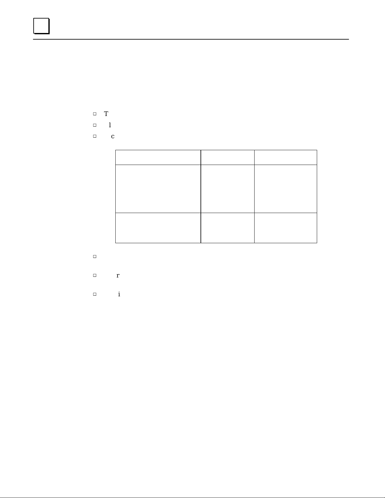
The most important ingredients in creating a successful PLC program are a thorough
understanding of the application itself, and a good measure of common sense.
The first step in creating a PLC application program is planning.
h
The desired sequence of program actions is determined.
h
All of the required inputs and outputs are identified and listed.
h
Each input and output is associated with a PLC memory location. For example:
Device Designation Memory Location
Star t switch
Limit switch on conveyor line
Syrup tank #1, level detector
Syrup tank #2, level detector
Conveyor line optical sensor
Conveyor line motor star ter
Operator warning light
Signal to bottle capper
h
The program (like the short example program on the facing page) is created with a
Input 1
Input 2
Input 3
Input 4
Input 5
Output 1
Output 2
Output 3
Discrete Input Table 1
”2
”3
”4
”5
Discrete Output Table1
”2
”3
programming device and transferred to the PLC.
h
Before the system begins full operation, the program is tested and any corrections
that are needed are made.
h
The final version of the program is transferred to the PLC, and the application is
ready to go.
1-2 Micro PLC Programmer’s Guide – April 1994
GFK-0804B
Page 11
PLC Programs
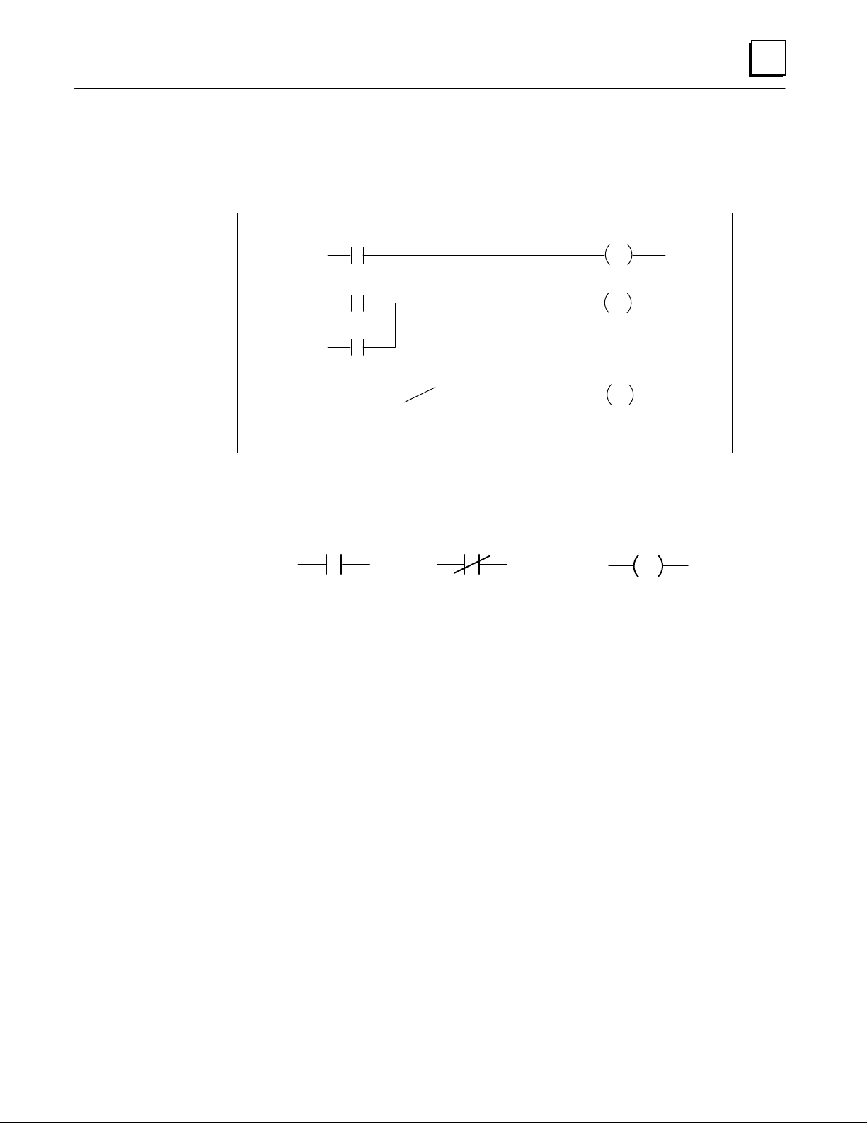
A typical PLC application program is created in a format called ladder logic.
1
46101
Input 1
1
Input 2
2
Input 3
Input 4 Input 5
3
Output 1
Output 2
Output 3
Each symbol in the ladder logic represents a type of input, output, or other program
action. There are many types of symbols. The three symbols shown above are:
Inputs Output
normally–open
normally–open
contact
contact
normally–closed
contact
coil
46102
In the ladder logic, each line or group of lines that ends in an action being performed, such
as an output being sent, is called a rung. In the example above, there are three rungs.
Power Flow in a Program
The PLC executes the logic in the ladder from top to bottom, one rung at a time. Within
each rung, the execution flows from left to right. This movement of program execution
through the ladder can also be thought of as power flow. In the example:
Rung 1: Input 1 represents a switch. It is shown in the ladder logic program as a
“normally–open” contact. When the switch is turned on, the input 1 contact closes and power flows across rung 1 to the coil labelled Output 1.
Rung 2: Rung 2 begins at the left side with two lines of logic that lead to the same
output on the right. In this type of rung, which can have several lines
beginning on the left, the output is ON if any of the input lines can be
completed. In this rung, if either Input 2 or Input 3 is closed, Output 2 is
turned ON.
Rung 3: Rung 3 illustrates the use of multiple inputs in the same line of logic. All
of these inputs must be completed for the output to be ON. In this example, Input 4 must be closed (active), and Input 5 must be closed (inactive)
for Output 3 to be set to ON.
1-3GFK-0804B Chapter 1 Programming for the Micro PLC
Page 12
1
The Micro PLC Instruction Set
Programs for a PLC are created from the elements provided in its Instruction Set. The
Instruction Set for the GE Fanuc Micro PLC includes both basic relay-replacement
contacts and many advanced program functions:
H
Contacts
h
Normally-open Contact
h
Normally-closed Contact
h
P ositive T ransition Contact
h
Negative Transition Contact
H
Outputs
h
Output coil
h
Set coil
h
Reset coil
h
Master Control Relay
h
Skip/Jump
H
Timers
h
On Timer
h
Off Timer
H
Counters
h
Up Counter
h
Down Counter
H
Math functions
h
Addition
h
Subtraction
h
Multiplication
h
Division
H
Move functions
h
Move
h
Block Move
h
Indirect Move
H
Comparison functions
h
Equal
h
Not Equal
h
Greater Than
h
Less Than
h
Greater Than or Equal to
h
Less Than or Equal to
H
Logical operation functions
h
AND
h
Inclusive OR
h
Exclusive OR
h
Shift Right
h
Shift Left
h
Not
1-4 Micro PLC Programmer’s Guide – April 1994
GFK-0804B
Page 13
Programming Devices and Formats
Programs for the Micro PLC can be created using a computer that is equipped with the
programming software, or using a Hand-held Programmer.
Programming with the Programming Software
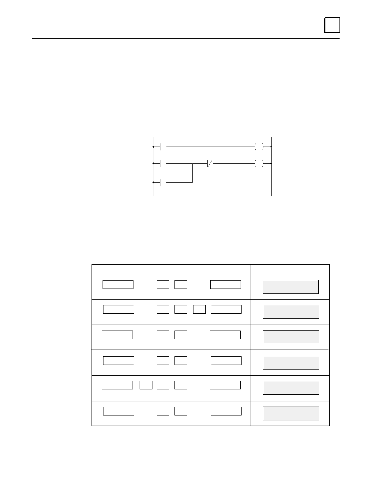
Programs created with the programming software are in traditional ladder logic format:
1
I0001
I0002
C0001
I0003 C0001
O0030
Chapter 2 describes programming with the programming software.
Programming on a Hand-held Programmer
Equivalent programs are easily created on the Hand-held Programmer. For example:
Key Operations HHP Displays
ISTART
OOUT
ENTER1
ENTER3 0
STA I001
Empty location
OUT O030
Empty location
46011
ISTART
COR
F3AND
COUT
ENTER2
ENTER1
ENTERI 3
ENTER1
Chapter 3 describes programming with a Hand-held Programmer.
ST A I002
Empty location
OR C0001
Empty location
AND NOT I003
Empty location
OUT C0001
Empty location
1-5GFK-0804B Chapter 1 Programming for the Micro PLC
Page 14

1
Memory Types and Addresses
Memor y Map
Type Total Non
Retentive
I
O
R
IR
OR
C
C
C
C
256 1 – 256 none no yes no no
256 1 – 256 none yes yes no no
512 1 – 384 385 – 512* no yes yes yes
256 1 – 256 no not applicable not applicable yes no
256 1 – 256 no not applicable not applicable yes no
1017 1 – 768 769 – 1017 yes yes no no
1 1018 0.1 sec clock for use as input in application program (read only).
1 1019 Startup scan coil for use as input in application program. (read only)
1 1021 Hold output coil for use in application program (read only).
Non-retentive and Retentive Registers
Data assigned to retentive memory is saved if power is removed from the Micro PLC.
Retentive
Use for Timer
or Counter
Coil?
General
Purpose
Internal Coil?
Use as
General
Purpose
Register?
Use as
Indirect
Register
Reference?
Non-retentive registers are cleared to zero when power is removed, and when the
Micro PLC is switched from Stop mode to Run mode.
* Reserved Registers
Retentive Registers 501 through 512 should not be used in your application program;
they are reserved.
Constants and Register Values in a Program
Many program functions for the Micro PLC use either constants, or variables in registers.
Constant values are limited to 32757 maximum. Single-register variables are limited to
65535 maximum.
1-6 Micro PLC Programmer’s Guide – April 1994
GFK-0804B
Page 15

Special Coils
The Micro PLC provides three special-purpose coils:
H
H
H
0.1 Sec Clock (C1018)
Coil C1018 is a pulse generator. The pulse width is shown below. This coil is a read-only
coil. It can only be used as a program input, not as an output.
1
0.1 sec clock
start–up scan coil
hold output coil
46103
Pulse
signal
50msec
0.1 sec
This coil should be used as a one-shot contact that feeds a regular coil.
Star t-up Scan Coil (C1019)
When the controller starts operating, this coil goes ON for one scan. It is a read-only coil.
It can only be used as a program input, not an output.
Run/power on
Stop/power off
1 Scan
46104
Hold Output Coil (C1021)
This coil can be used to control the state of the program outputs when the PLC is put in stop
mode. As a group, all of the outputs can either hold their last state, or be set to OFF.
If all outputs should hold their last state, set coil C1021 to ON (1).
If all outputs should be set to OFF, set coil C1021 to OFF (0).
Note: This function takes precedence over the Clear Data function of the programming
software (key F7 in the Online menu).
1-7GFK-0804B Chapter 1 Programming for the Micro PLC
Page 16
1
Programming for an Analog Expander Unit
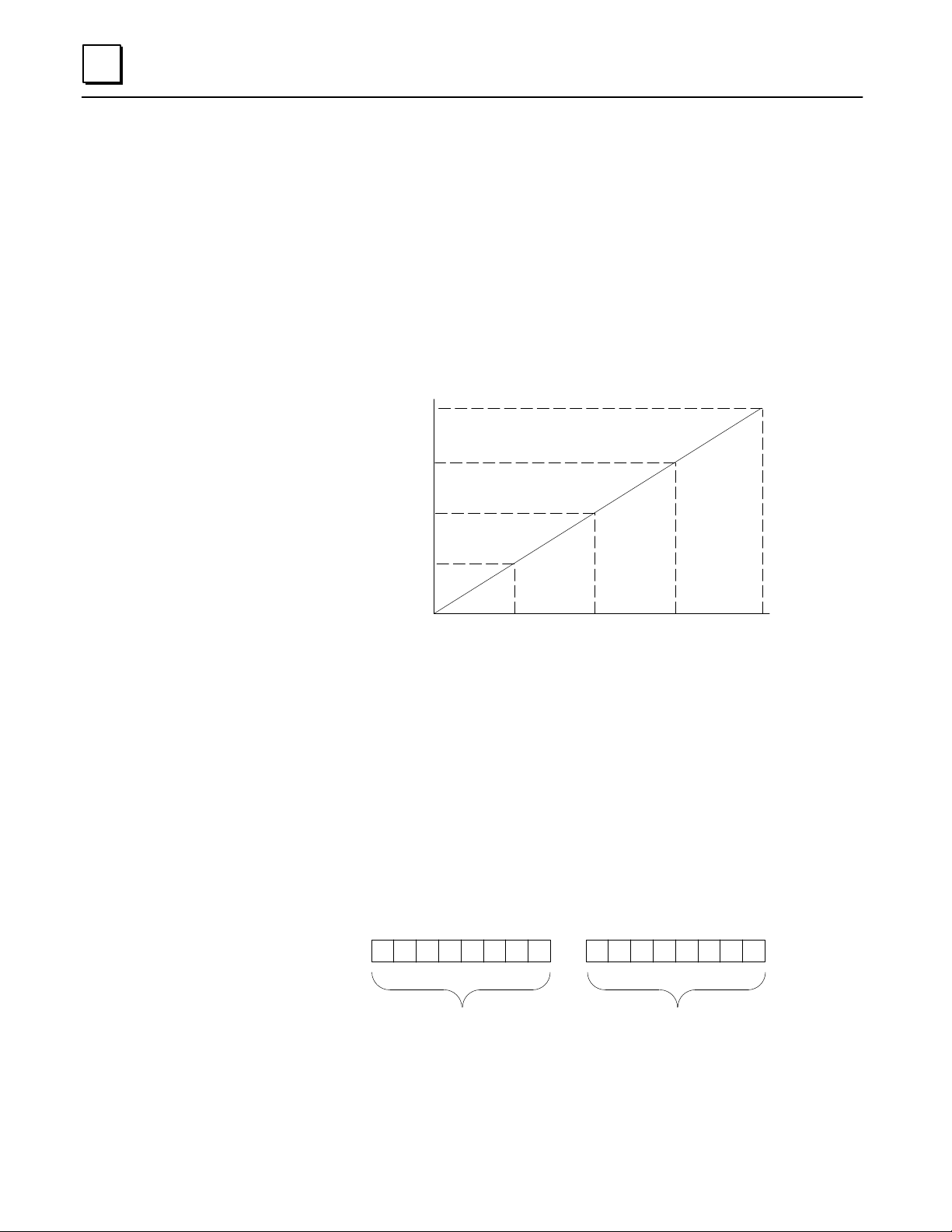
Analog Scaling
The Analog Expander Unit provides two 8-bit analog inputs and one 8-bit analog output.
Scaling for an analog input or output is:
Minimum: 0 volts = 0mA = 0 bits
Maximum: 9.969 volts = 19.922mA = 255 bits
Some examples of equivalent values are:
V olts
9.969
7.5
2.5
5
0
0
12864 192
255 Bits
46190
Analog References
In a program, input 1 uses reference IR1. Input 2 uses reference IR2. The analog output
uses reference OR1.
Maximum Values
The program references (IR1, IR2, and OR) used to store analog data are 16 bits each.
However, the module utilizes only the lower 8 bits. Therefore, it is important not to
inadvertently program a value greater than 255, which would cause incorrect results.
For example, suppose you programmed an output value of 258. This is shown below in
bits. Because the module uses only the lower 8 bits, it would interpret the value
incorrectly.
00000001 00000010
Higher 8 bits not used
1-8 Micro PLC Programmer’s Guide – April 1994
Only these 8 bits are used
GFK-0804B
Page 17
Programming Examples
Two simple programming examples are shown below .
Example #1:
For an analog input, the program might read the input value and turn on a discrete
output when the analog input reaches a specific value. In this example, the program
compares the value of the first analog input (IR1) with a value stored in register R4. If
the analog input is greater than that value, then a discrete output (O18) is turned on.
O18
[IR1 > R4]
The output that is turned on might represent an actual output device such as a switch, or
a logical output that is used elsewhere in the program.
Example #2:
1
The logic below might be used for an analog output.
[R3 ! OR1]
In this example, each program scan, the Move function copies the content of register R3
to reference OR1, which is the reference used by the analog output.
1-9GFK-0804B Chapter 1 Programming for the Micro PLC
Page 18

Chapter 2 Programming with the Programming
2
Softwar e
This chapter explains how to create and edit a program using the Micro PLC
programming software.
H
Using the Programming Functions
H
Creating a Program Rung
H
Running the Programming Software
H
Editing Basics
H
Horizontal and Vertical Lines in a Rung
H
Element Labels and Rung Labels
H
Editing a Completed Rung
H
Deleting Rungs
section level 1 1
figure bi level 1
table_big level 1
H
Moving Rungs
H
Copying Rungs
H
Searching for a Rung or Program Element
See the Micro PLC User’s Guide if you need information about:
H
Software installation
H
Software functions
H
Changing to another directory
H
Loading a program file
H
Saving a Program File
H
Clearing a program from RAM memory
H
Printing an application program
H
Exiting the programming software
H
Setup parameters
H
Files and file-handling
H
Monitoring a program online in the PLC
GFK-0804B
2-1
Page 19

2
Using the Programming Functions
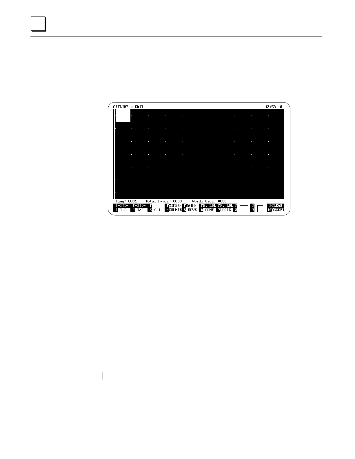
When you select Offline (F3) from the Main menu, the application program currently in
the computer’s RAM memory appears.
If there is no program currently in RAM memory, the screen looks lik e this:
The window shows the current rung, total number of rungs in the program, and
program size in words. If you want to quit the Programming window, use the ESC key.
Programming Operations
In the Offline window, use the function keys to select a programming operation.
Rung Create (F1) to create a new program rung
Rung Delete (F2) to delete a program rung
Search (F3) to search for a type of function or operand
Edit (F4) to edit the rung at the top of the screen. After pressing
F4, – moves the cursor within the rung. PgUp, PgDn
moves from rung to rung.
Rung Move (F5) to move a program rung
Rung Copy (F6) to duplicate a program rung
" Search (F7)
# Search (F8)
Label Display (F9) to toggle between absolute and symbolic display
Check (F10) to check program syntax.
to search previous rungs (search backward)
to search next program rungs (search forward)
2-2 Micro PLC Programmer’s Guide – April 1994
GFK-0804B
Page 20
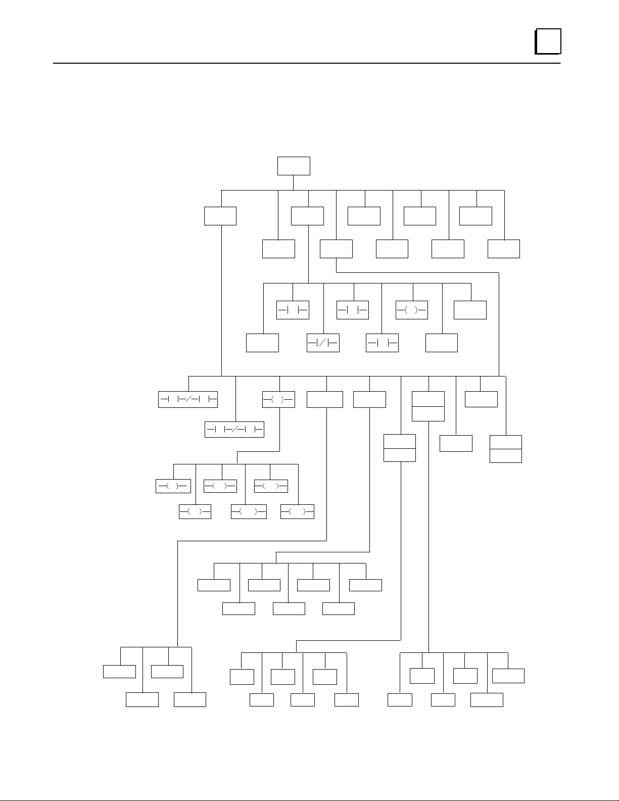
Programming Functions
2
46105
OFFLINE
RUNG
CREATE
RUNG
DELETE
SEARCH
RUNG MOVE SEARCH
EDIT RUNG COPY SEARCH CHECK
"
#
"
RUNG
"
#
MATH / MOVETIMER/COUNTER
REF
R LABEL
LOGIC
LABEL
DISPLAY
REF
VER T LINE
"
RST SKIP
E LABEL
COMP
HORI LINE
CLEAR
ACCEPT
ON TIMER
OFF TIMER
UP COUNTER
SET MCR END
( * ) MUL
( – ) SUB
.EQ.
DOWN
COUNTER
.NE.
MOVE
( / ) DIV B–MOVE
.GT .
.GE.
.LE.
I–MOVE( + ) ADD
SHIFT REG
LEFT
SHIFT REG
RIGHT
AND XOR
IOR.LT .
NOT
2-3GFK-0804B Chapter 2 Programming with the Programming Software
Page 21
2
Creating a Program Rung
Select Rung Create (F1) to create a new program rung. If there are already rungs in the
program, the new rung will appear at the top of the page.
You can now enter a program element in the highlighted location. Use the ESC key if
you want to return to a previous menu.
In the Edit window, use the function keys to select a program element.
–| |– (F1) Normally-open contact. See page 4-4.
–| " |– (Shift, F1) Positive transition contact. See page 4-4.
–| / |– (F2) Normally-closed contact. See page 4-4.
–| #|– (Shift, F2) Negative transition contact. See page 4-4.
–( )– (F3) Output. See page 4-11.
Timer/Counter (F4) Timer or Counter. See pages 4-16 and 4-19.
Math/Move (F5) Math or Move function. See pages 4-22 and 4-30.
Comp (F6) Compare function. See page 4-36.
E. Lbl (Shift, F6) Element label. See page 2-8.
Logic (F7) Logic function. See page 4-38.
R. Lbl (Shift, F7) Rung label. See page 2-8.
________ (F8) Draw horizontal (serial) line. See page 2-7.
(F9) Draw or erase vertical (parallel) line. See page 2-7.
Accept (F10) Exit editing a rung. See page 2-6.
Clear (Shift, F10) Delete (clear) the rung being edited. Be careful.
Note: the Delete key on your keyboard will remove the
element at the current position in either Rung Edit or
Rung Create mode.
2-4 Micro PLC Programmer’s Guide – April 1994
GFK-0804B
Page 22

Running the Programming Softwar e
The programming software can be run from diskette, or installed on a hard disk. For
installation instructions and information about the files on the software diskette, refer to
the Micro PLC User’s Guide (GFK -0803).
Running the Programming Software from a Hard Disk
1. Go to the directory where you placed the MICRO.EXE file. For example:
C:>CD MICRO (Press the Enter key)
2. To run the programming software, type:
C:\MICRO>MICRO (Press the Enter key)
2
Running the Programming Software Directly from a Diskette
1. Go to the DOS prompt if it is not already displayed:
A:>
2. Place the diskette containing the programming software into the appropriate
disk ette drive (for e xample, drive A). To run the programming software, type:
A:>MICRO (Press the Enter key)
3. Place a formatted diskette into drive B. You can use this diskette for storing
configuration files.
2-5GFK-0804B Chapter 2 Programming with the Programming Software
Page 23
2
Editing Basics
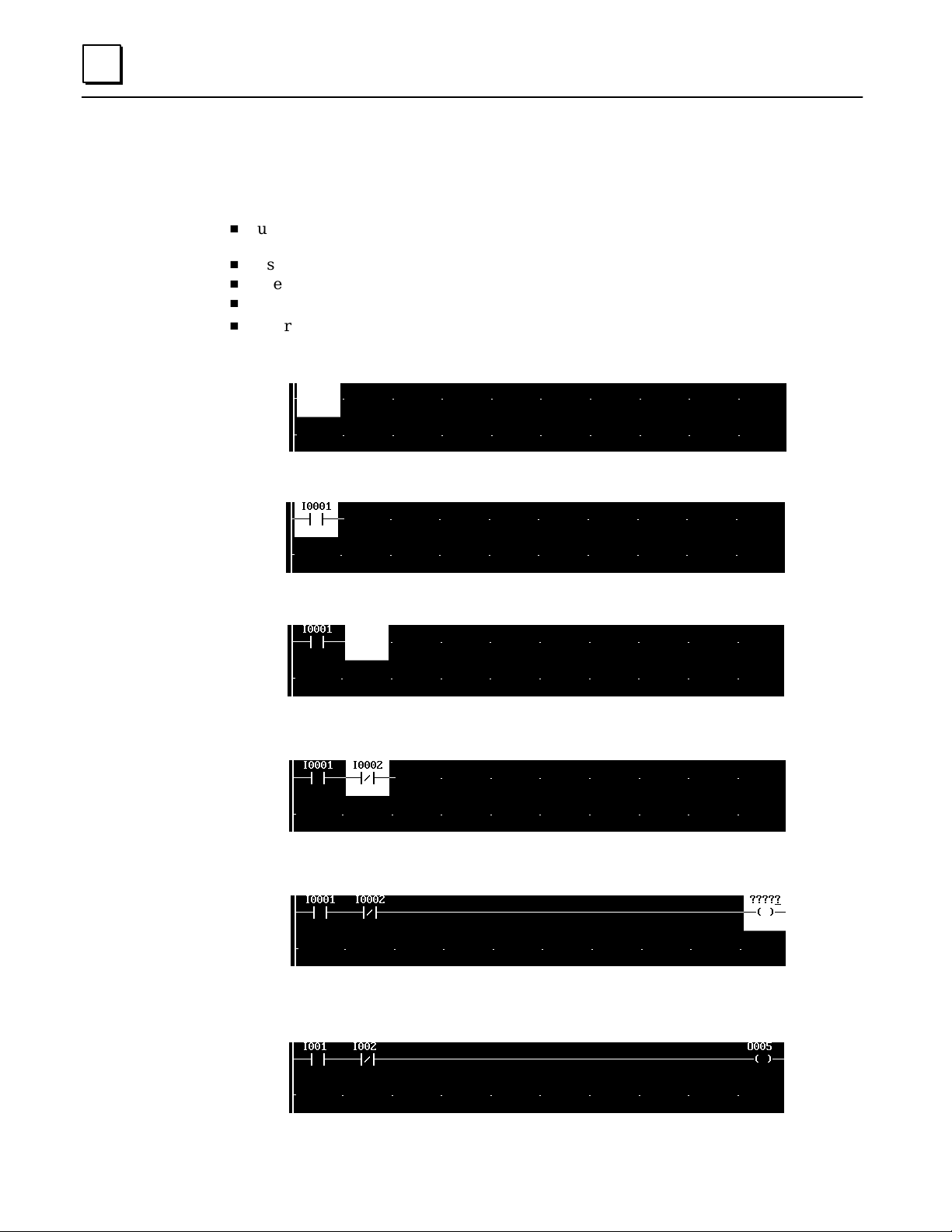
After selecting Rung Create (F1):
H
H
H
H
H
use the function keys to create an element and enter a reference value. For example,
“I2”. (Note that the element reference cannot be entered as “2I”).
use the cursor keys to move to another position in the rung being edited
use your keyboard Delete key to delete a rung element.
use your keyboard ESC key to quit a function or to return to the previous menu.
To create another r ung, press R ung Create (F1). The new rung appears.
Initial display:
Enter a function at the highlighted location. (Use the function keys)
Move the highlight box. (Use the cursor keys)
Enter the next function:
When you enter a coil, the highlight box automatically goes to the end of the rung:
After entering all the logic for the rung, use the Accept (F10) key to add it to the program. The
disappearance of the highlight box shows that the software is not presently in Edit mode.
2-6 Micro PLC Programmer’s Guide – April 1994
GFK-0804B
Page 24

Horizontal and Vertical Lines in a Rung
Horizontal and vertical lines are used to connect elements of a multi-line rung.
If a rung has more than one line of logic, move the highlight box down to the start
of the next line. Enter the first element on that line.
To add a horizontal line to the logic, move the highlight box to the location for the line.
2
Use the (F8) key to add the horizontal line.
Use the Delete key on your keyboard to remove a horizontal line.
To add a vertical line to the logic, move the highlight box to the end location for the line.
Use the (F9) key to add the vertical line.
Y ou must use the (F9) key to remove a vertical line.
2-7GFK-0804B Chapter 2 Programming with the Programming Software
Page 25
2
Element Labels and Rung Labels
Element labels and rung labels are text that can be added to a program and viewed in
Offline mode by selecting the Label Display function. Element and rung labels will also
appear in their entirety in a hard copy printout or a print to disk. The first 5 characters of
an element label can also be viewed in Online mode. (Think about this when selecting
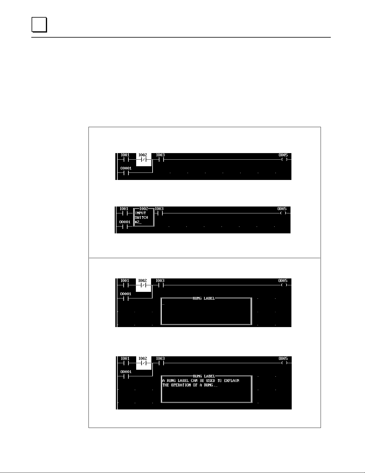
the element label.) To create an element label or rung label, follow the instructions
below, in Edit or Create Rung mode.
To create a label for an individual element, move the highlight box to that
element. Press Enter to clear element edit. Then, press Shift, F6.
Enter the text for the element label. Pressing the Enter (return) key ends text
entry. Enter spaces if you want the label to have more than one line.
After you press the Enter key , the element label disappears.
To create a label for a rung, press Shift, F7.
Enter the text for the rung label. Pressing the Enter (return) key ends text
entry. Enter spaces if you want the label to have more than one line.
After you press the Enter key , the element label disappears.
2-8 Micro PLC Programmer’s Guide – April 1994
GFK-0804B
Page 26
Editing a Completed Rung
After using the Accept (F10) key to save a rung, the rung can be changed by selecting
Edit (F4) with the Offline function keys. The same basic programming features are
available in both Create mode and Edit mode. Refer to the previous descriptions of
program functions and editing techniques.
While editing a rung, you can delete, add, or change rung elements within the rung as
described below and on the following pages.
If you want to delete or move an entire rung, see page 2-13.
Selecting a Rung to Edit
To select a rung for display or editing, use the cursor keys to scroll the program up or
down on the screen. Or you can use the Search function to locate a specific rung,
element, or reference.
Bring the rung you want to edit to the top of the screen.
To edit the rung, use the Edit (F4) key. In Edit mode, you can add elements to the rung,
or edit the elements that are already there. You can then use the cursor keys to move
the cursor within a rung, and the PgUp, PgDn keys to move from rung to rung.
2
Editing a Rung Element
In Edit mode, the highlight box selects the rung element that can be edited.
Use the cursor keys to move to the highlighted box.
Enter the reference and address, then press the Enter key or a cursor key to go to the
next rung element.
Deleting a Rung Element
Delete the highlighted element by pressing the Delete key on your keyboard. (If the
small edit cursor is displayed in the highlight box, first press the Enter key to remove it).
This creates an empty space in the rung. If you do not want to add an element at that
location, insert a horizontal line (F8).
2-9GFK-0804B Chapter 2 Programming with the Programming Software
Page 27

2
Adding a Contact to a R ung
To add a contact to a rung, move the highlight box to the location for the new contact.
Add the contact using its function key. Enter a reference for the contact and press the
Enter key, or use the cursor keys to move to a new position.
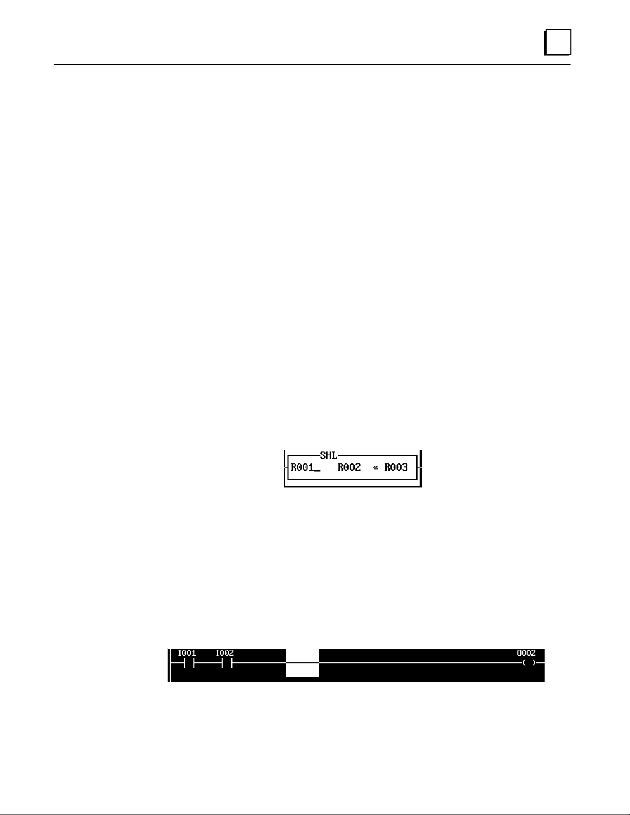
Adding a Program Function to a Rung
If you want to add something other than a contact (for example, an Equal function) to a
rung, first create a space for it. Position the highlight box where the function should
begin, then press your keyboard Delete key. If the element to be added requires 2 or 3
consecutive spaces, move the highlight box, then press the Delete key again.
Move the highlight cursor back to the leftmost empty space:
Add the function using its function key. Edit the function as necessary.
2-10 Micro PLC Programmer’s Guide – April 1994
GFK-0804B
Page 28

2
Replacing a Rung Element with a Similar Element
To replace a rung element with a similar element (for example, to replace a normally-open
contact with a normally-closed contact), select the element with the highlight box.
Press the function key that corresponds to the new element type. Edit it if necessary.
Replacing a Rung Element with a Horizontal Line
To replace a rung element with a horizontal line, select it with the highlight box:
Then , select the horizontal line (F8).
2-11GFK-0804B Chapter 2 Programming with the Programming Software
Page 29

2
Replacing a Rung Element with a Dissimilar Element
To replace an element with an element of a different type (for example, to change a
normally-open contact to an Equals function), select the element with the highlight box.
First, delete the element by pressing the Delete key on your keyboard. (If the small edit
cursor is displayed in the highlight box, first press the Enter key to remove it).
This creates an empty space in the rung. If you do not want to add an element at that
location, insert a horizontal line (F8).
If you want to add an element at that location, use the appropriate function key to enter it.
You may need to delete more than one existing element to insert a new element if the
new element is wider than the element it is replacing.
2-12 Micro PLC Programmer’s Guide – April 1994
GFK-0804B
Page 30
Deleting Rungs
To delete one or more rungs, use the Rung Delete (F2) key. The software prompts:
The first number that appears is the number of the rung that is now at the top of the
screen. If you want to delete just that rung, press the Enter key.
If you want to delete a different rung, or a group of rungs, enter their rung numbers
then press the Enter key.
If you want to quit the Delete function without deleting any rungs, press the ESC key.
2
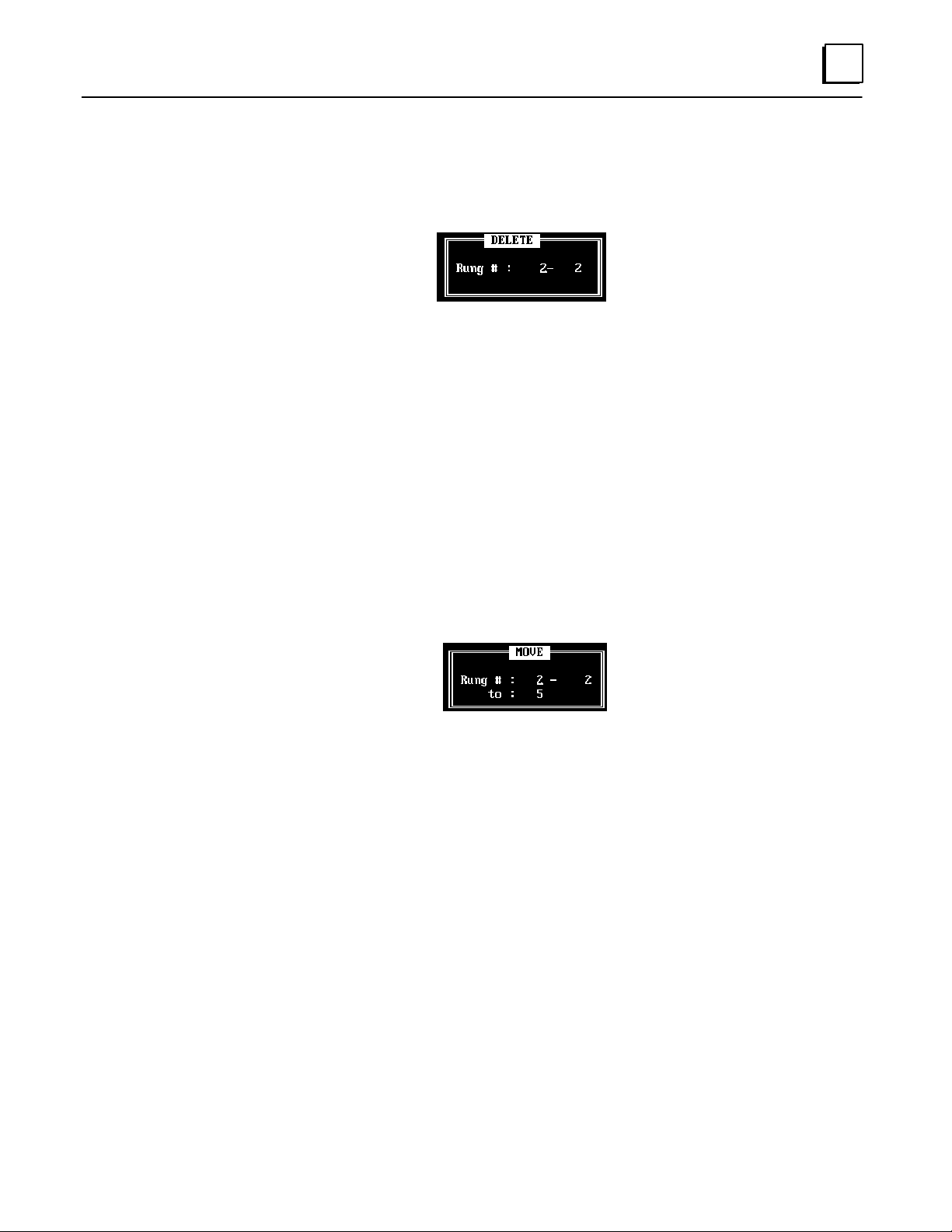
Moving Rungs
You might want to move rungs to make a program more understandable, or to group
rungs together that work with each other.
To move one or more rungs, use the Rung Move (F5) key. The software prompts:
The first number that appears is the number of the rung that is now at the top of the screen.
Enter the numbers of the r ungs to be moved, and the number of the rung you want to
insert them in front of. Press the Enter key.
If you want to quit the Move function without moving any rungs, press the ESC key.
2-13GFK-0804B Chapter 2 Programming with the Programming Software
Page 31

2
Copying Rungs
You might want to copy rungs and then make simple changes to the rungs rather than
enter new rungs.
To copy one or more rungs, use the Rung Copy (F6) key. The software prompts:
The first number that appears is the number of the rung that is now at the top of the screen.
Enter the numbers of the rungs to be copied, and the number of the rung you want to
insert the copied rungs in front of. P ress the Enter key.
If you want to quit the Copy function without copying any rungs, press the ESC key.
2-14 Micro PLC Programmer’s Guide – April 1994
GFK-0804B
Page 32

Searching for a Rung or Program Element
You can search for a specific program rung, contact or coil, reference address, number , or
program function. Select Search (F3) in Offline mode, then use the function keys described
below to select the target of the search. Finally, use the " Search (F7) and # Search (F8) keys
to specify the search direction.
Rung (F1) rung number
Type in a rung number and
press the Enter key.
–] [– (F2) normally-open contact
–] / [– (F3) normally-closed contact
–] " [– (F4) positive transition contact
–] # [– (F5) negative transition contact
–( )– (F6) coil
2
Type in a reference address and
press the Enter key.
Ref (F7) reference
Type in a reference address and
press the Enter key.
Number (F8) number
Type in a number and
press the Enter key.
Func (F10) program function
Type in a number and
press the Enter key.
2-15GFK-0804B Chapter 2 Programming with the Programming Software
Page 33

Chapter 3 Programming with a Hand-held Programmer
section level 1 1
3
This chapter explains how use a Hand-held Programmer for programming the
GE F anuc Micro PLC.
H
Program Listing
H
Program Transfer
H
Entering Program Logic
H
Inserting a Rung Element
H
Deleting a Rung Element, Rung or Program In Memory
H
Searching
H
Programming Examples Using the HHP
figure bi level 1
table_big level 1
GFK-0804B
3-1
Page 34

3
Program Listing
To display the program listing, press the ENTER key from the powerup screen.
Program Transfer
To transfer a program, press the XFER key from the program listing screen.
PROGRAM START
Empty location
TRANSFER TO/FROM
PLC PROM PC
The Hand-held Programmer will transfer the program to or from the Micro PLC,
EEPROM, or the programming software in the computer.
3-2 Micro PLC Programmer’s Guide – April 1994
GFK-0804B
Page 35

Entering Program Logic
The steps below show how to create a simple example program.
Example Program
I0001
O0030
3
46011
I0002
C0001
I0003
C0001
Hand-Held Programmer Key Operation and Displays
h
use the ENTER key to accept a command.
h
On the display, “empty location” refers to the current unoccupied program line.
Key Operations HHP Displays
IST ART
OOUT
ENTER1
ENTER3 0
STA I001
Empty location
OUT O030
Empty location
ISTART
ENTER2
STA I002
Empty location
COR
ENTER1
OR C0001
Empty location
F3AND
ENTERI 3
AND NOT I003
Empty location
COUT
ENTER1
OUT C0001
Empty location
3-3GFK-0804B Chapter 3 Programming with a Hand-held Programmer
Page 36

3
Inserting a Rung Element
The steps below show how to insert an element in a simple example program.
Example Program
I1
O17
I5
"
In this example, the statement OR PTRAN I005 is inserted between the existing
statements:
AND NOT I003
OR PTRAN I005
OUT O017
I3
O17
I5
Element
added to the program as shown
"
46106
is to be
Hand-Held Programmer Key Operation and Displays
h
use the SRCH key to locate the ladder logic rung to be edited. The display selects the
last element in the selected rung.
h
Use the PREV key to select the previous element. In this example, it is:
AND NOT I003 (see below).
h
use the PREV key to scroll the program display backward.
h
use the NEXT key to scroll the program display forward.
Key Operations HHP Displays
SRCH
PREV
ENTER1
IOR
ENTER5F1
OUT O017
Empty location
AND NOT I003
OUT O017
OR PTRAN I005
OUT O017
3-4 Micro PLC Programmer’s Guide – April 1994
GFK-0804B
Page 37

Deleting a Rung Element, Rung or Program In Memory
The steps below show how to use the HHP’s delete function key to delete a program or
part of a program in memory.
Hand-Held Programmer Key Operation and Displays
h
use the SRCH key to locate the ladder logic rung to be edited. The display selects the
last element of the r ung. Use the PREV key to select a previous element.
h
use the PREV key to scroll the program display backward.
h
use the NEXT key to scroll the program display forward.
h
use the DEL key and F1 key to delete a program element.
h
use the DEL key and F2 key to delete a rung.
h
use the DEL key and F3 key to delete a program.
Key Operations HHP Displays
3
DEL
Delete the program element currently displayed.
DEL
Delete the program rung currently displayed.
DEL
Delete the current program.
F1
F2
F3
Elem Rung Prog
F1 F2 F3
DELETE
Elem Rung Prog
DELETE
Elem Rung Prog
DELETE PROGRAM
ENTER=YES, ESC=No
3-5GFK-0804B Chapter 3 Programming with a Hand-held Programmer
Page 38

3
Deleting a Rung Element
The steps below show how to delete an element of a simple example program.
Example Program
I5
I6
I3
I1
O17
I1
Element
removed from the program
as shown.
AND NOT I003
OR PTRAN I005
OUT O017
Hand-Held Programmer Key Operation and Displays
h
use the SRCH key to locate the ladder logic rung to be edited. The display selects the
last element of the r ung. Use the PREV key to select a previous element.
h
use the DEL key and F1 key to delete a program element.
h
use the PREV key to scroll the program display backward.
h
use the NEXT key to scroll the program display forward.
46107
is to be
Key Operations HHP Displays
SRCH
PREV
DEL
F1
3-6 Micro PLC Programmer’s Guide – April 1994
ENTER1
OUT O017
Empty location
AND I1
OUT O017
AND NOT I003
OUT O017
GFK-0804B
Page 39

Searching
3
Use the SRCH key to locate a rung, element, or operand in a program. The steps below
show how to search for an operand, element, or rung umber, or the start or end of the
program.
Hand-Held Programmer Key Operation and Displays
Key Operations HHP Displays
0
enter
number
or
ENTERI/O
ENTERF1
0
ENTER1
ENTER
SRCH
The search operand may be I, O, IR, OR, C, or R.
SRCH
This example searches for a counter (either up or down).
SRCH
This example searches for rung number 10.
SRCH
To locate the start of the program, search for rung 0.
SRCH
To locate the end of the program, search with no rung number.
CNTR F2
AND I001
OUT O017
C R001 T o 100
Empty location
OUT O040
Empty location
PROGRAM START
STA I001
OUT O040
Empty location
PLC TRANSFER
Open Rung
PLC TRANSFER
PLC in RUN Mode
An open rung or other program error was encountered.
The PLC was in Run mode when the transfer was attempted.
3-7GFK-0804B Chapter 3 Programming with a Hand-held Programmer
Page 40

3
Programming Examples Using the HHP
Example 1
Ladder Diagram Key Operations
46108
Example 2
I1
I3
I5
I2
I4
I6
C1
STAR T
AND
STAR T
AND
OR
STAR T
AND
OR
OUT
F3 (NOT)
Ladder Diagram Key Operations
I1
I3
I5
I2
I4
I6
C2
STAR T
OR
OR
STAR T
OR
OR
AND
OUT
F3 (NOT)
I1
I2
I3
I4
I5
I6
C1
I1
I3
I5
I2
I4
I6
C2
ENTER
ENTER
ENTER
ENTER
ENTER
ENTER
ENTER
ENTER
ENTER
46109
ENTER
ENTER
ENTER
ENTER
ENTER
ENTER
ENTER
ENTER
Example 3
Ladder Diagram Key Operations
I6
"
C2 C21
O38
C51
C38
C51
3-8 Micro PLC Programmer’s Guide – April 1994
C1
C1
C4
C2
STAR T
STAR T
AND
OR
AND
STAR T
AND
STAR T
AND
OR
AND
OR
AND
OUT
F1 (PTRAN)
F3 (NOT)
F3 (NOT)
F3 (NOT)
F3 (NOT)
F3 (NOT)
I6
C2
C21
C1
O38
C51
C38
C51
C1
C4
C2
46110
ENTER
ENTER
ENTER
ENTER
ENTER
ENTER
ENTER
ENTER
ENTER
ENTER
ENTER
ENTER
ENTER
ENTER
GFK-0804B
Page 41

Example 4
I6
Ladder Diagram Key Operations
I1
I2
"
I4 I5
I9
I3
C5
I7
I8
I4
C2
STAR T
OR
STAR T
OR
AND
STAR T
OR
AND
OR
STAR T
OR
OR
AND
AND
OUT
F1 (PTRAN)
F3 (NOT)
F3 (NOT)
F3 (NOT)
F3 (NOT)
I1
I4
I2
I5
I6
I9
I7
I3
C5
I8
I4
C2
3
4611 1
ENTER
ENTER
ENTER
ENTER
ENTER
ENTER
ENTER
ENTER
ENTER
ENTER
ENTER
ENTER
ENTER
ENTER
ENTER
Example 5
C1
C1
C2
C2
C3
C3
C4
Ladder Diagram Key Operations
RI
ONTMR
"
"
"
"
"
"
"
10
R2
UPCTR
60
R3
UPCTR
60
R4
UPCTR
24
C1
C2
C3
C4
STAR T
STAR T
TIMER
OUT
STAR T
STAR T
CNTR
OUT
STAR T
STAR T
CNTR
OUT
STAR T
STAR T
CNTR
OUT
F1 (PTRAN)
F1 (ONTIM)
F1 (PTRAN)
F1 (PTRAN)
F1 (UPCNT)
F1 (PTRAN)
F1 (PTRAN)
(F1 (UPCNT)
F1 (PTRAN)
F1 (PTRAN)
F1 (UPCNT)
C1
R1
10
C1
C1
C2
R2
60
C2
C2
C3
R3
60
C3
C3
C4
R4
24
C4
46112
ENTER
ENTER
ENTER
ENTER
ENTER
ENTER
ENTER
ENTER
ENTER
ENTER
ENTER
ENTER
ENTER
ENTER
ENTER
ENTER
ENTER
ENTER
ENTER
ENTER
ENTER
ENTER
ENTER
3-9GFK-0804B Chapter 3 Programming with a Hand-held Programmer
Page 42

Chapter 4 The Micro PLC Instruction Set
Instruction Set Summary
Math Functions
section level 1 1
4
This chapter defines the individual logic elements that can be combined to make a
program for the Micro PLC.
figure bi level 1
table_big level 1
H
H
H
H
H
Contacts
h
Normally-Open Contact
h
Normally-Closed Contact
h
P ositive T ransition Contact
h
Negative Transition Contact
Coils
h
Output Coil
h
Set/Reset Coil Pair
h
Master Control Relay/End Coil
Pair
h
Skip/End Coil Pair
Timers
h
On Timer
h
Off Timer
Counters
h
Up Counter
H
h
A ddition (ADD)
h
Subtraction (SUB)
h
Multiplication (MUL)
h
Division (DIV)
H
Move Functions
h
Move
h
Block Move
h
Indirect Move
H
Compare Functions
H
Logic Operations
h
W ord AND
h
Inclusive OR (IOR)
h
Exclusive OR (XOR)
h
Shift Register Right
h
Shift Register Left
GFK-0804B
h
Down Counter
h
NOT
4-1
Page 43

4
Instruction Set Summary
Operation Ladder Symbol Description
Normally-open contact
Contact
Output
Timer
Counter
/
"
#
SET
RST
MCR
SKIP
END
ONTMR
R###
XXXX
OFTMR
R###
XXXX
UPCTR
R###
XXXX
Normally-closed contact
Positive transition
Negative transition
Output coil
Set coil
Reset coil
Master Control Relay
Skip/jump operation
Ending operation for a skip or jump
On Timer
V ariable Register R### (R1 – R500)
Timer Setting XXXX (Timebase 0.1S)
Off Timer
V ariable Register R### (R1 – R500)
Timer Setting XXXX (Timebase 0.1S)
Up Count
V ariable Register R### (R1 – R500)
Timer Setting XXXX
DNCTR
R###
XXXX
[???+???! ???]
Math
[???–???! ???]
Functions
[???x???! ???]
[???B ???! ???]
4-2 Micro PLC Programmer’s Guide – April 1994
Down Counter
V ariable Register R### (R1 – R500)
Timer Setting XXXX
Addition
Subtraction
Multiplication
Division
GFK-0804B
Page 44

Operation Ladder Symbol Description
4
Move
Operations
Compare
Function
[???! ???]
L
[???E???! ???]
N
[???! @???]
[S1 = S2]
[S1 > S2]
[S1 < S2]
[S1 > S2]
[S1 < S2]
[S1 0 S2]
A
[???N???! ???]
D
I
[???O???! ???]
R
Move
Block Move
Indirect Move
Continue when S1 = S2
Continue when S1 > S2
Continue when S1 < S2
Continue when S1 >
Continue when S1 < S2
Continue when S1 0 S2
AND
IOR
S2
XYO
111
100
010
000
XYO
111
101
011
000
Logic
Operation
X
[???O???! ???]
R
S
[???H???! ???]
R
S
[???H???! ???]
L
[??? ! ???]
XOR
Shift Right
Shift Left
Not
XYO
110
101
011
000
4-3GFK-0804B Chapter 4 The Micro PLC Instruction Set
Page 45

4
Contacts
The Micro PLC instruction set includes the following contacts:
–| |– Normally-open contact. Passes power flow to the right when its
associated reference is = 1.
–| " |– Positive transition contact. Passes power flow to the right for one
program cycle when its associated reference changes from 0 to 1.
–| / |– Normally-closed contact. Passes power flow to the right while its
associated reference is = 0.
–| # |– Negative transition contact. Passes power flow to the right for one
program cycle when its associated reference changes from 1 to 0.
Each of these contact types is described more fully on the pages that follow. If you are
using the programming software, refer to the programming instructions below. If you
are using the Hand-held Programmer, refer to the instructions for each contact type.
General Programming Software Instructions for Contacts
1. Select the contact type using the function keys:
–| |– (F1) Normally-open contact.
–| " |– (Shift, F1) Positive transition contact.
–| / |– (F2) Normally-closed contact.
–| #|– (Shift, F2) Negative transition contact.
The selected contact type is displayed:
2. Enter an appropriate address. For a contact, enter an address in input (I), output (O),
or internal (C) memory. For example: I4. You don’t need to enter leading zeros.
Note that you cannot enter the reference as “4I”.
3. Press the Enter key. The memory type and address appear:
If you want to change the memory type and address, press the Enter key . A cursor
appears next to the address. Type in the new memory type and address. Press the Enter
key again to accept the new entry.
4-4 Micro PLC Programmer’s Guide – April 1994
GFK-0804B
Page 46

Normally-Open Contact
A Normally-Open contact passes power flow to the right when the associated reference
is equal to 1.
Programming Software Instructions
If you are using the programming software, refer to the instructions on the opposite
page.
Examples and HHP Instructions
The HHP programming keystrokes to create a Normally-Open contact depend on its
position in a rung, as explained below.
Programming Normally-Open Contact at the Start of a R ung
4
When a Normally-Open contact is the first element of the rung, program a START, as
shown below.
46114
Ladder Diagram Hand-held Programmer
I1 O17
Timing Diagram
Input I1
Output O17
1
0
1
0
0
0
ST ART
OUT
I1
O17
The output O17 status follows the
signal of input I1, when I1–1,
output O17=1.
4-5GFK-0804B Chapter 4 The Micro PLC Instruction Set
Page 47

4
Programming a Normally-Open Contact in Series
When a Normally-Open contact is not the first element of the rung, program an AND
with the HHP, as shown below. The example shows how to use the HHP to program a
Normally-Open contact at the first and second positions in a rung.
46115
Ladder Diagram Hand-held Programmer
I1 O17
Timing Diagram
Input I1
Input I2
I2
START
AND
OUT
I1
I2
O17
AND operation of inputs I1 and I2;
output O17 is 1 when I1 and I2 are
both 1.
Output O17
Programming a Normally-Open Contact in Parallel
To enter a Normally-Open contact in parallel, as shown by I2 in the following example,
program an OR with the HHP.
46116
Ladder Diagram Hand-held Programmer
I1 O17
I2
ST ART
OR
OUT
I1
I2
O17
Timing Diagram
Input I1
Input I2
Output O17
4-6 Micro PLC Programmer’s Guide – April 1994
OR operation of inputs I1 and I2.
The output O17 is 1 when either I1
or I2 is 1.
GFK-0804B
Page 48

Normally-Closed Contact
A Normally-Closed contact passes power flow to the right when the associated reference
is equal to 0.
Programming Software Instructions
If you are using the programming software, refer to the instructions on page 4-4.
Examples and HHP Instructions
The HHP programming keystrokes to create a Normally-Closed contact depend on its
position in a rung, as explained below.
Programming Normally-Closed Contact at the Start of a R ung
4
When a Normally-Closed contact is the first element of the rung, program a
START NOT, as shown below.
Ladder Diagram Hand-held Programmer
I2 O18
Timing Diagram
Input I2
Output O18
ST ART
OUT
The output O18 status is the
reverse signal of input I2, when
I2=1, output O18=0.
F3 (NOT)
46017
II2
O18
4-7GFK-0804B Chapter 4 The Micro PLC Instruction Set
Page 49

4
Programming a Normally-Closed Contact in Series
When a Nor mally-Closed contact is not the first element of the rung, program an
AND NOT with the HHP, as shown below. The example shows how to use the HHP to
program a Normally-Closed contact at the first and second positions in a rung.
46018
Ladder Diagram Hand-held Programmer
I3 O18 START
Timing Diagram
Input I3
I4
AND
OUT
F3 (NOT)
F3 (NOT)
I3
I4
O18
NAND operation of inputs I3 and
Input I4
Output O18
I4; output O18 is 1 when I3 and I4
are both 0.
Programming a Normally-Closed Contact in Parallel
To enter a Normally-closed contact in parallel, as shown by I3 in the following example,
program an OR NOT with the HHP.
46019
Ladder Diagram Hand-held Programmer
I1 O17
I2
ST ART
OR
OR
OUT
F3 (NOT)
I1
I2
I3
O17
I3
Timing Diagram
Input I1
Input I2
Input I3
Output O17
4-8 Micro PLC Programmer’s Guide – April 1994
OR operation of inputs I1 and I2
and the reverse signal of I3. The
output O17 is 1 when either I1 or
I2 is 1 or I3 is 0.
GFK-0804B
Page 50

Positive Transition Contact
The Positive Transition contact passes power flow to the right for one program cycle
when its reference changes from 0 to 1.
Programming Software Instructions
If you are using the programming software, refer to the instructions on page 4-4.
Example and HHP Instructions
4
46020
Ladder Diagram Hand-held Programmer
I1 O17
"
Timing Diagram
Input I1
Output O17
! z
1 scan
START
OUT
Upon the rising edge signal of
input I1, output O17 is activated.
The status of O17 remains 1 for
only one program cycle.
F1 (PTRAN)
I1
O17
4-9GFK-0804B Chapter 4 The Micro PLC Instruction Set
Page 51

4
Negative Transition Contact
The Negative Transition contact passes power flow to the right for one program cycle
when its reference changes from 1 to 0.
Programming Software Instructions
If you are using the programming software, refer to the instructions on page 4-4.
Example and HHP Instructions
46021
Ladder Diagram Hand-held Programmer
I1 O17
#
Timing Diagram
Input I1
Output O17
! z
1 scan
START
OUT
Upon the falling edge signal of
input I1, output O17 is activated.
The status of O17 remains 1 for
only one program cycle.
F2 (NTRAN)
I1
O17
4-10 Micro PLC Programmer’s Guide – April 1994
GFK-0804B
Page 52

Coils
4
The Micro PLC instruction set includes the following coils:
–( )– Coil. The basic type of program output.
–(SET)– Set coil. Used to set a specified reference to 1.
–(RST)– Reset coil. Used to reset the same specified reference to 0.
–(MCR)– Master Control Relay . Used to set a group of outputs to 0.
–(SKIP)– Skip. Used to cause a group of outputs to hold last state.
–(END)– End of MCR or Skip
Using Coil Pairs
The following types of coils must always be used in pairs. If one of these instructions is
used in the program, the paired instruction must also exist somewhere in the program.
SET RST Set and Reset
MCR END Master Control Relay and End MCR
SKIP END Skip (rungs) to rung containing End
General Programming Software Instructions for Coils
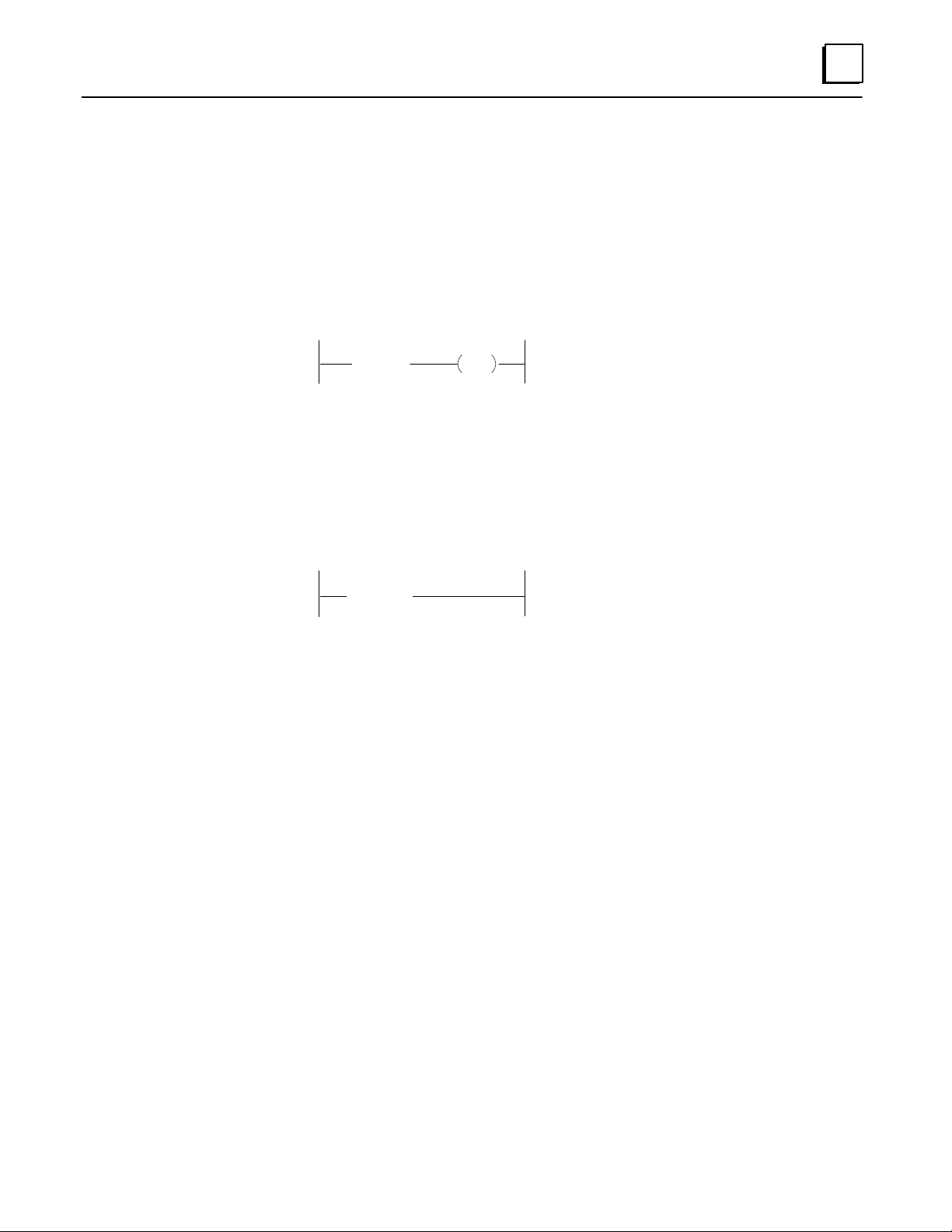
1. Select –( )– (F3), then use the assigned function key(s) to select an output type:
–( )– (F1) Coil
–(SET)– (F2) Set coil
–(RST)– (F3) Reset coil
–(MCR)– (F4) Master Control Relay
–(SKIP)– (F5) Skip
–(END)– (F6) End of MCR or Skip
The selected coil type appears at the end of the rung:
2. Enter an appropriate address. For a coil, enter an address in output (O) or internal
coil (C) memory. For example, C0001. You don’t need to enter leading zeros.
3. Press the Enter key. The memory type and address appear:
If you want to change the memory type and address, press the Enter key . A cursor
appears next to the address. Type in the new memory type and address. Press the Enter
key again to accept the new entry.
4-11GFK-0804B Chapter 4 The Micro PLC Instruction Set
Page 53

4
Output Coil
The basic type of output coil is controlled by conditional logic within the same rung.
When the coil receives power flow from logic to its left in the rung, the reference
associated with that coil is set to 1. When no power flow is received, the reference is 0.
The state of output coils may also be affected if they are between an MCR/End MCR coil
pair or a Skip/End coil pair , as explained on the following pages.
Programming Software Instructions
If you are using the programming software, refer to the instructions on page 4-11.
Examples and HHP Instructions
46022
I1 O17
Timing Diagram
Input I1
Output O17
Output O18
Ladder Diagram Hand-held Programmer
START
OUT
O18
START
OUT
Output O17 follows the status of
input I1. Output O18 is
1
0
unconditional; it always remains 1.
I1
O17
O18
4-12 Micro PLC Programmer’s Guide – April 1994
GFK-0804B
Page 54

Set/Reset Coil Pair
Set Reset
The Set/Reset coil pair can be used to control the state of an associated reference. The Set
coil sets the reference to 1. The reference (O17 in the example below) STAYS set to 1 until
it is reset to 0 by the Reset coil. Notice that the Set and Reset coil are programmed with
the same associated reference; that of reference being controlled.
In the example below, the Set coil and Reset coil are shown in adjoining rungs of logic.
That is not necessary, however.
Programming Software Instructions
If you are using the programming software, refer to the instructions on page 4-11.
Example and HHP Instructions
4
I1 O17
I2 O17
Timing Diagram
Input I1
Input I2
Output O17
SET RST
Ladder Diagram Hand-held Programmer
SET
RST
START
OUT
START
OUT
F2 (SET)
F2 (RESET)
This is a flip-flop operation. Input I1 sets
output O17 to 1. Output O17 remains 1
even if I1 changes to 0. Output O17 is only
reset to 0 when I2 is activated.
When both I1 and I2 are ON, the last
occurrence in the scan (RST in this case)
takes precedence.
46023
I1
O17
I2
O17
4-13GFK-0804B Chapter 4 The Micro PLC Instruction Set
Page 55

4
MCR End
Master Control Relay/End Coil Pair
The MCR/End coil pair can be used to turn off one or more outputs in the program,
regar dless of the state of any inputs or other conditional logic to those outputs. The rungs with
the outputs to be controlled must be located between the Master Control Relay coil and
its paired End coil in the program.
In the example below, the MCR and End MCR coil control the states of outputs C1 and
O17. While the Master Control Relay coil receives power flow from its conditional logic
(in the example, it is contact I1), all output coils within the MCR/End MCR pair go to 0.
Programming Software Instructions
If you are using the programming software, refer to the instructions on page 4-11.
Example and HHP Instructions
Timing Diagram
Input I1
Coil C1
Input I2
Output O17
MCR
Ladder Diagram Hand-held Programmer
I1
I2 O17
MCR
C1
END
ST ART
OUT
ST ART
OUT
ST ART
OUT
OUT
END
More MENU
C1
I2
O17
More MENU
This is a Master Control Relay operation.
When I1 is 0, the program till the END
command operates normally.
When input I1 is 1, all outputs before the
END are disabled.
46024
I1
F1 (MCR)
F3 (END MCR)
4-14 Micro PLC Programmer’s Guide – April 1994
GFK-0804B
Page 56

Skip/End Coil Pair
)
)
Skip End
The Skip/End coil pair can be used to cause one or more outputs in the program to stay
in their current state (1 or 0), regardless of the state of any inputs or other conditional logic to
those outputs. The rungs with the outputs to be controlled must be located between the
Skip coil and its paired End coil in the program.
In the example below, the Skip and End coil control the states of outputs O17 and O18.
While the Skip coil receives power flow from its conditional logic (in the example, it is
contact I1), all output coils within the Skip/End pair hold their last states.
Programming Software Instructions
If you are using the programming software, refer to the instructions on page 4-11.
Example and HHP Instructions
4
Timing Diagram
Input I1
Input I2
Output O17
Input I3
Output O18
SKIP
Ladder Diagram Hand-held Programmer
I1
I2 O17
I3 O18
SKIP
END
START
OUT
START
OUT
START
OUT
START
OUT
END
F3 (NOT)
This is a Skip to END operation. When
input I1 is 0, the Skip command is not
performed.
When input I1 is 1, all outputs till END
are on hold, and are not affected by input
conditions.
46025
I1
More MENU F2 (SKIP
I2
O17
I3
O18
More MENU F3 (END
4-15GFK-0804B Chapter 4 The Micro PLC Instruction Set
Page 57

4
Timers
The Micro PLC instruction set provides two T imers:
On Timer Sets an output to 1 after a specified time period. See page 4-17.
Off Timer Sets an output to 0 after a specified time period. See page 4-18.
Programming Software Instructions for Timers
Timers require input logic in the same rung. This can be entered either before selecting
the Timer function, or after as described below. Note that the enable line for a timer
CANNOT contain parallel branches or instructions. If this type is logic is desired, place it
in another rung, using it to drive an internal coil which then drives the timer.
1. To enter a Timer, select Timer/Counter (F4), then On Timer (F1) or Off Timer (F2).
2. For the top parameter , enter a register location for the PLC to store the current
value of the timer as it increments. For example: R001. Then press the Enter key.
3. For the other parameter, enter the timer length in intervals of 1/10 second. For
example, for a 10-second timer, enter 100.
If you want to change a parameter, press the Enter key. Type in the new value and
press the Enter key again to accept the new entry.
4. Enter the other logic required by the Timer:
A. Logic in the top line to enable timing. Timing only takes place while this line
passes power flow to the Timer.
B. Logic in the bottom line that will clear the current Timer value to 0 when it
passes power flow to the Timer.
C. An output that will be turned On (for an On Timer) or Off (for a Down Timer)
when the Timer reaches the desired value (in this example, 10 seconds).
5. Use the Accept (F10) key to add the rung to the program.
4-16 Micro PLC Programmer’s Guide – April 1994
GFK-0804B
Page 58

On Timer
h
4
The On Timer turns ON an output after a specified time period. The time period can be
from 0 to 6553.5 seconds. However, if a constant is used for the Preset value, the time
period can be from 0 to 3276.7 seconds. To program a timer function, enter two inputs
(in the example below, I1, and I2), and two parameters (R1 and 100 in the example).
The first input controls operation of the timer . Timing only occurs while I1 is 1. The
second input to the timer clears the current timer value to 0.
The first timer parameter is a register memory location for PLC to store the current timer
value.
The second timer parameter is the timer length, in intervals of 0.1 second. If this number
should always be the same, you can enter it directly, as shown in the example. Or, if you
want to be able to change the timer length using the Hand-held Programmer, instead
enter a register from R385 to R500 as the second parameter for the timer. The current
timer value (in R1 below) will not increment beyond its programmed length (time
period), even if I1 remains closed and I2 remains open.
Programming Software Instructions
If you are using the programming software, refer to the instructions on page 4-16.
Example and HHP Instructions
Ladder Diagram Hand-held Programmer
iming Diagram
Input I1
Input I2
Register R1
I1 C1
R1
ONTMR
I2
100
100
0
START
START
TIMER
OUT
F1
I1
I2
R1
100
C1
When I1 is 1, the timer is enabled. The timer
setting is:
100 x 0.1 = 10 Sec.
During the operation of the timer, if I1
switches to 0, the timer is on hold. When I1 is
1 again, the timer resumes timing.
46026
Coil C1
When the timer reaches the set value (10
seconds), output coil C1 activates.
Input I2 is used to reset the timer. When bot
I1 and I2 are on, the timer remains reset.
4-17GFK-0804B Chapter 4 The Micro PLC Instruction Set
Page 59

4
Off Timer
The Off Timer turns OFF an output after a specified time period. The time period can be
from 0 to 6553.5 seconds. However, if a constant is used for the Preset value, the time
period can be from 0 to 3276.7 seconds.
To program a timer function, enter two inputs (in the example below, I1, and I2), and
two parameters (R1 and R385 in the example). In this example, the timer length is not
specified directly. Instead, this example uses the register R385 as the second parameter.
In this case, register R385 contains the value 100. The timer length can be placed in that
register either by program logic or from the Hand-held Progammer or programming
software.
When the program encounters a register location as the second parameter of the timer, it
looks in that register for the value it contains, and uses that value as the timer length. So
for this example, timing is the same as for the previous example.
The current timer value (in R1 above) will not increment beyond its programmed length
(time period), even if I1 remains closed and I2 remains open.
Programming Software Instructions
If you are using the programming software, refer to the instructions on page 4-16.
Example and HHP Instructions
Ladder Diagram Hand-held Programmer
I1 C1
Timing Diagram
Input I1
Input I2
Register R1
Coil C1
R1
OFTMR
I2
R385
100
0
START
START
TIMER
OUT
F1
I1
I2
R1
R385
C1
When I1 is 1, the timer is started. The
timer setting is:
100 x 0.1 = 10 Sec.
During the operation of the timer, if I1
switches to 0, the timer is on hold. When
I1 is 1 again, the timer resumes timing,
When the timer reaches the set value (10
seconds), output coil C1 deactivates.
46027
4-18 Micro PLC Programmer’s Guide – April 1994
Input I2 is used to reset the timer. When
both I1 and I2 are ON, the timer remains
reset.
GFK-0804B
Page 60

Counters
4
The Micro PLC instruction set includes two Counters:
Up Counter Sets an output to 1 when the counter is equal to a specified
value. See page 4-20.
Down Counter Sets an output to 1 when the counter reaches 0. See page 4-21.
Programming Software Instructions for Counters
Counters require input logic in the same rung. This can be entered either before selecting
the Counter function, or after as described below. Note that the count line for a counter
CANNOT contain parallel branches or instructions. If this type is logic is desired, place it
in another rung, using it to drive an internal coil which then drives the timer.
1. Select Timer/Counter (F4), then Up Counter (F3) or Down Counter (F4).
2. For the top parameter , enter a register location for the PLC to store the current
value of the counter as it increments. For example: R001. Then press the Enter key.
Register R001, used in this example, is not a “retentive” register; it is cleared if power
goes off. If the current count value should be saved with the power off, use a
retentive register instead. (R385 - R500)
3. For the other parameter, enter the counter total. If this should always be the same,
enter the number. If you want to be able to change the counter total, instead enter a
register location. The counter total can then be placed in that register by program
logic, from the Hand-held Programmer or by the programming software (if a
retentive register is used).
If you want to change a parameter, press the Enter key. Type in the new value and
press the Enter key again to accept the new entry.
4. Enter the other logic required by the Counter:
A. Logic in the top line to either increment (Up Counter) or decrement (Down Counter)
the count value. The counter counts each scan that this line has power flow.
B. Logic in the bottom line to reset to the count total (to 0 for an Up Counter, to the
maximum value for a Down Counter). If both top and bottom lines are active,
the counter will be reset.
C. An output that will be turned On when the Timer reaches the desired value.
5. Use the Accept (F10) key to add the rung to the program.
4-19GFK-0804B Chapter 4 The Micro PLC Instruction Set
Page 61

4
Up Counter
The Up Counter turns on an output when the count reaches a specified value (from 0 to
65535 if a register is used to load the counter, or 0 to 32676 if a constant is used). The
output remains on only as long as the count is equal to the specified value. If the count
increases past the specified value, the output goes back to 0.
To program a counter function, enter two inputs (in the example below, I1, and I2), and
two parameters (R1 and 5 in the example).
The first input increments the count value. In this example, each time the Positive
Transition contact transitions on, the count total stored in R1 goes up by 1. The second
input to the counter resets the count total (here, in R1) to 0. It also deactivates the output
coil.
The first parameter of the Up Counter is a register containing a value that is being
incremented (usually, by an input in the application program). Register R1, used in this
example, is not a “retentive” register; it is cleared if power goes off. If the current count
value should be saved with the power off, use a register from R385 to R500.
The second parameter is the counter total. If this number should always be the same,
you can enter it directly, as shown in the example. Or, if you want to be able to change
the counter total, instead enter a register from R385 to R500 as the second parameter for
the timer (see the example Down Counter).
Programming Software Instructions
If you are using the programming software, refer to the instructions on page 4-19.
Example and HHP Instructions
Ladder Diagram Hand-held Programmer
Timing Diagram
Input I1
Input I2
Register R1
I1 C1
"
I2
1
R1
UPCTR
5
4
3
2
1
0
5
0
ST ART
ST ART
CNTR
OUT
F1
F1
I1
I2
R1
5
C1
Each time input I1 transitions on, the
content of register R1 is incremented.
When it reaches 5, output coil C1
activates.
Input I2 is used to reset counter R1 to
0. It also deactivates coil C1.
46128
Coil C1
4-20 Micro PLC Programmer’s Guide – April 1994
GFK-0804B
Page 62

Down Counter
4
The Down Counter turns on an output when the count reaches zero (from 65535 to 0 if a
register is used to load the counter, or 32767 to 0 if a constant is used). To program a
counter function, enter two inputs (in the example below, I1, and I2), and two
parameters (R2 and R386 in the example).
The first input decrements the count value. In this example, each time the Positive
Transition contact transitions on, the count total stored in R1 goes down by 1. The
second input to the counter resets the count total (here, in R1) to its maximum value. It
also deactivates the output coil.
The first parameter of the Down Counter is a register containing the value that is being
incremented (usually, by an input in the application program). Register R1, used in this
example, is not a “retentive” register; it is cleared if power goes off. If the current count
value should be saved with the power off, use a register from R385 to R500.
The second counter parameter is the counter total. If this number should always be the
same, you can enter it directly, as shown in the example Up Counter. Or, if you want to
be able to change the counter total, instead enter a register from R385 to R500 as the
second parameter for the counter (see the example). The counter total can then be
placed in that register, either by program logic, or from the Hand-held Progammer or
programming software.
When the program encounters a register location as the second parameter of the timer, it
looks in that register for the value it contains, and uses that value as the timer length. So
for this example, timing is the same as for the previous example.
Programming Software Instructions
If you are using the programming software, refer to the instructions on page 4-19.
Example and HHP Instructions
Ladder Diagram Hand-held Programmer
Timing Diagram
Input I1
Input I2
Register R2
I1 C2
"
I2
4
R2
DNCTR
R386
55
4
3
2
0
1
ST ART
ST ART
CNTR
OUT
F1
F2
I1
I2
R2
R386
C2
Each time input I1 transitions on, the
content of register R1 is decremented.
When it reaches 0, output coil C2
activates.
Input I2 is used to reset counter R2 to
5. It also deactivates coil C2.
46129
Coil C2
4-21GFK-0804B Chapter 4 The Micro PLC Instruction Set
Page 63

4
Math Functions
The Micro PLC instruction set includes these Math functions:
For the Math functions, all numbers are assumed to be positive. There are no negative
numbers.
P ower flow from a Math function is always true.
Addition (ADD)
Addition Adds together two numbers and places the total in a specified
register.
Subtraction The Subtraction function subtracts one number from another
and places the result in a specified register.
Multiplication The Multiply function multiplies one number by another and
places the result in two consecutive registers.
Division The Division function divides one number by another, and
places the result in two consecutive registers.
The Addition function adds together two numbers and places the total in a specified
register.
46130
number + number = register
The numbers added can be constants, as in the second addition shown on the facing
page, or the contents of register locations in memory. For example, if R1 contains the
value 23 and you add the constant 16 to it, then register R3 will contain the value 39.
Maximum Total
The maximum total for the Addition function is 65535. If the total exceeds 65535, only
the excess is placed in the specified register. F or example:
1st number 2nd number T otal in register
50,000 + 50,000 = 34464 (excess above 65536)
The program can compare the total with the two numbers that were added. If the total is
less than either number, a “rollover” has occurred.
4-22 Micro PLC Programmer’s Guide – April 1994
GFK-0804B
Page 64

Programming Software Instructions
1. Select Math/Move (F5).
2. Select +ADD (F1) from the Math/Move function keys.
3. Enter the first number to be added. This can be either a constant, or a register
location that will contain the number to be added. For example: R001. Then press
the Enter key.
4. Enter the second number to be added. This can also be a constant or a register
location. Press the Enter key.
5. Enter a register location to contain the total. Press the Enter key.
Examples and HHP Instructions
4
46131
Ladder Diagram Hand-held Programmer
I1
"
[R1+R2 ! R3]
[R1+ 1! R4]
ST ART
MATH
OUT
ST ART
MATH
OUT
F1
F1
F1 (DROP)
F1
F1 (DROP)
I1
R1
R2
R3
R1
1
R4
In the first rung of the example above, the Positive Transition contact I1 is used as
conditional logic to the Addition function. When I1 transitions on, the value in register
R2 is added to the value in register R1 and the total is placed in register R3.
In the second rung of the example, there is no contact placed before the Addition
function. That means it is executed unconditionally. Each program scan, 1 is added to the
value in R1.
In this example, since R1 is also one of the parameters of the first Addition function,
these two rungs of logic work together . Each program scan, the second rung increments
the value in R1 that is being added to the contents of R2.
4-23GFK-0804B Chapter 4 The Micro PLC Instruction Set
Page 65

4
Subtraction (SUB)
The Subtraction function subtracts one number from another and places the result in a
specified register .
The numbers can be constants, as in the first subtraction shown on the facing page, or
the contents of register locations in memory. For example, if R1 contains the value 100
and R4 contains the value 57, then register R3 will contain the value 43.
The second number (the number being subtracted) must be smaller than the first.
Otherwise the content of the specified register will “roll over” as shown by these
examples:
46132
number – number = register
1st number 2nd number T otal in register
100 – 10 = 90
0 – 1 = 65535
0 – 2 = 65534
The program should check to be sure that the second number is smaller than the first
before subtracting.
Programming Software Instructions
1. Select Math/Move (F5).
2. Select –SUB (F2) from the Math/Move function keys.
3. First, enter the number to be subtracted from. This can be either a constant, or a
register location that will contain the number. For example: R001. Then press the
Enter key.
4. Enter the number to be subtracted. This can also be a constant or a register location.
Press the Enter key.
5. Enter a register location to contain the result. Press the Enter key.
4-24 Micro PLC Programmer’s Guide – April 1994
GFK-0804B
Page 66

Examples and HHP Instructions
Ladder Diagram Hand-held Programmer
4
46133
I1
"
[R1– 5! R2]
[R3–R4 ! R5]
ST ART
MATH
OUT
ST ART
MATH
OUT
F2
F1
F2
F1
I1
R1
5
R2
R3
R4
R5
In the first rung of the example above, the Positive Transition contact I1 is used as
conditional logic to the Subtraction function. When I1 transitions on, 5 is subtracted from
the current value in register R1. The result is placed in register R2.
In the second rung of the example, there is no contact placed before the Subtraction
function. That means it is executed unconditionally. Each program scan, the value in R4
is subtracted from the value in R3. The result is placed in R5.
4-25GFK-0804B Chapter 4 The Micro PLC Instruction Set
Page 67

4
Multiplication (MUL)
The Multiply function multiplies one number by another and places the result in two
consecutive registers.
Two registers are needed to accommodate the larger numbers that might possibly result
from the multiplication. Only the first register (R3 above) is actually specified although
R3 and R4 will contain the result. Be sure not to use the second register for any other
purpose in the program.
The multiplication can be performed on constants or the contents of register locations in
memory.
If the result of the multiplication is 65535 or less, it is placed in the higher numbered register
and the lower numbered register is not used. If your application does not use numbers
above 65535 for multiplication or division, you do not need to understand how 32-bit
numbers are handled.
46134
R1 x R2 = R3 R4
Examples:
R1 R2 R3 R4
10 * 10 = 00000 00100 (0*65536 + 100)
100 * 1000 = 00001 34464 (1*65536 + 34464)
1000 * 1000 = 00015 16960 (15*65536 + 16960)
If you expect the result of the multiplication to be too large to use easily, you can use the
Division function on the result. See page 4-29.
Programming Software Instructions
1. Select Math/Move (F5).
2. Select *MUL (F3) from the Math/Move function k eys.
3. Enter the first number to be multiplied. This can be either a constant, or a register
location that will contain the number to be multiplied. For example: R001. Then
press the Enter key.
4. Enter the second number to be multiplied. This can also be a constant or a register
location. Press the Enter key.
5. Enter the first register of a two register location to contain the result. For example,
if you entered R003 as shown above, the result of the multiplication would be be
located in R003 and R004. Press the Enter key .
If the result of the multiplication is 65535 or less, it is placed in the higher numbered
register, and the lower numbered register (R003 in the example) is set to 0.
4-26 Micro PLC Programmer’s Guide – April 1994
GFK-0804B
Page 68

Example and HHP Instructions
Ladder Diagram Hand-held Programmer
4
46135
I1
"
[R1 x R2! R3]
ST ART
MATH
OUT
F1
F3
F1
I1
R1
R2
R3
In the example above, the Positive Transition contact I1 is used as conditional logic to the
Multiplication function. When I1 transitions on, the value in register R1 is multiplied by
the value in register R2. The result is placed in registers R3 (specified) and R4.
4-27GFK-0804B Chapter 4 The Micro PLC Instruction Set
Page 69

4
Division (DIV)
The Division function divides one number by another, and places the result in two
consecutive registers.
R1 B =R3 R4
R1 BR2 =R3 R4 R5
The numbers can be either constants or the contents of register locations.
When this function is programmed, only the first register of a pair is programmed; that
is, the first register of the pair where the result of the division will be placed, and the first
register of the number to be divided, (unless it is a constant). Although only the first
register of a pair is actually specified, it is important not to use the second register for
any other purpose in the program.
46136
Examples:
Whole # Remainder
R1 R2 R3 R4 R5
00000 01000 / 00010 = 00100 00000 ( 100 plus no remainder)
00000 01000 / 00012 = 00083 00004 ( 83 plus 4 remainder)
00001 01000 / 00002 = 33268 00000 ( 66536 / 2 = 33268, no remainder)
00010 01000 / 01000 = 00656 00360 (( 655360+1000) / 1000) = 656 plus
remainder of 360)
00000 01000 / 03000 = 00000 01000 ( 1000 / 3000 = 0, remainder 1000)
10000 00000 / 00010 = 00000 00000 (number is too large to represent as
00000 01000 / 00000 = LAST RESULT (but C1023 turns on to indicate
4-28 Micro PLC Programmer’s Guide – April 1994
a whole number plus a remainder)
that a divide by 0 was incorectly attempted.
GFK-0804B
Page 70

Using Division and Multiplication Functions Together
0
If a Multiplication produces a result that is too large to use easily (the results are greater
than 65535, and occupy two registers), you can divide the Multiplication result to scale
the result to use smaller numbers.
For example:
46137
R100 R101 R102 R103
4
Multiply:
Divide:
In this example, R105 would contain the whole number result of the division, and R106
would contain the remainder.
1000
R102 R103
00015 16960
1,000,000 / 1000 = 1000 with no remainder
x
1000
/
=
00015 16960
R104 R105 R106
=
1000
01000 00000
= 15*65536 + 16960 = 1,000,00
Programming Software Instructions
1. Select Math/Move (F5).
2. Select /DIV (F4) from the Math/Move function keys.
3. First, enter the number to be divided. This can be either a constant, or a two-register
location that will contain the number to be added. For example: R001 above
represents the two-register location R001 and R002. Press the Enter key.
4. Enter the number to divide by . This can also be a constant or a one-register location.
Press the Enter key.
5. Enter the first register of a two register location to contain the result. For example,
if you entered R004 as shown above, the result of the division would be be located in
R004 and R005. Press the Enter key.
4-29GFK-0804B Chapter 4 The Micro PLC Instruction Set
Page 71

4
Move Functions
The Micro PLC instruction set includes these Math functions:
Move
The Move function copies 1 word (16 bits) of data to a specified memory location. The
possible choices are:
Move The Move function copies 1 word (16 bits) of data to a speci-
fied memory location.
Block Move The Block Move function copies a selectable amount of data to
a specified memory location. It copies more than 16 bits at a
time.
Indirect Move The Indirect Move function copies a constant or the content of
register to a variable register location.
Register > Register
Input (I) > Register
Register > Coil (C)
Coil (C) > Register
Register > Output (O)
Programming Software Instructions
1. Select Move (F5) from the Math/Move function keys.
2. Enter the number to be moved. This can be a constant, or the contents of a specified
bit or register memory location. In the example shown, the Move function copies 16
bits located from I001 through I016. Then press the Enter key.
3. Enter a memory location for the data to be copied to. The memory type (bit or
register) must be compatible with the data being moved. Press the Enter key. The
software will not let you select an incompatible memory type.
4-30 Micro PLC Programmer’s Guide – April 1994
GFK-0804B
Page 72

Examples and HHP Instructions
46138
Ladder Diagram Hand-held Programmer
I1
"
[R1! R2]
[I1! R3]
ST ART
MOVE
OUT
ST ART
MOVE
OUT
F1
F1
F1
F1
F1
In the first example rung above, a transitional contact controls execution of a Move
function. That Move function copies the contents of register R1 to register R2.
The second example rung has no conditional logic; it ex ecutes each program scan. That
Move function copies 16 bits from I1 to I16 into register R3.
I1
R1
R2
I1R3
4
4-31GFK-0804B Chapter 4 The Micro PLC Instruction Set
Page 73

4
Block Move
The Block Move function copies a selectable amount of data to a specified memory location.
It works like a Move function, except that it copies more than 16 bits at a time. The options
are explained below:
Option Example Description
Register > Register R001 0002 > R004 Copies the contents of R001–R002
into R004–R005.
R010 R020 > R100 Copies the contents of R010 to R100 in
incremental order , according to the
length specified in R020. For example,
if R020 contained the number 2, then
the contents of R010–R011 would be
copied onto R100–R101.
Coil (C) > Coil (C) C001 0010 > C014 Copies Internal Relay status coils
C001–C010 into C014–C023.
Output (O) > Output (O) O001 0016 >O033 Copies 16 output bits from
O001–O016 into O033–O048.
Input (I) > Output (O) I004 0016 > O033 Copies 16 input bits (I001–I019) into
outputs O033–O048.
Input (I) > Coil (C) I016 0006 > C020 Copies 6 input bits (I016–I011) into
internal coils C010–C025.
Coil (C) > Output (O) C001 0010 > O003 Copies 10 bits from internal coils
C001–C010 into outputs
O003–O012.
Programming Software Instructions
1. Select B–Move (F6) from the Math/Move function keys.
2. Enter the number to be moved. This can be a constant, or the contents of a specified
memory location (see above). For example: R001. Then press the Enter key.
3. Enter the data length. This can be a constant or the contents of a specified register
location. The number may represent either bits or words of data, according to the
data type being moved.
4. Enter a memory location to contain the result. Press the Enter key.
4-32 Micro PLC Programmer’s Guide – April 1994
GFK-0804B
Page 74

Examples and HHP Instructions
46139
Ladder Diagram Hand-held Programmer
I1
"
L
[R1E 5! R10]
N
L
[O9E 8! O17]
N
ST ART
MOVE
OUT
ST ART
MOVE
OUT
F2
F1
F2
F1
In the first example rung above, when transitional contact I1 goes on, 5 registers (R1 –
R5) are copied to locations R10 – R14.
In the second rung, each program scan 128 bits (8 x 16) are copied from O9 – O137 to
locations O17 – O124. Since the locations being copied from overlap the locations being
copied into, this function actually has the effect of shifting 128 bits eight bits to the “left”
(that is, to higher locations) in memory.
I1
R1
5
R10
O9
8
O17
4
4-33GFK-0804B Chapter 4 The Micro PLC Instruction Set
Page 75

4
Indirect Move
The Indirect Move function copies a constant or the content of register to a variable
register location. The first part of this function specifies the data to be copied. The second
part is a register that points to the actual register where the data will be placed. This
allows the register where the data is placed to be changed as required for the program.
In the example on the facing page, an Indirect Move function copies the content of
register R002 into a register which is pointed to by register R003. During one program
scan, R003 might point to register R020. In another scan, it might point to register R021.
Specifying a Location in the Pointer Register
Ordinarily, the variable register for an Indirect Move function is placed into the pointer
register by a Move instruction in the application program. It is also possible to enter a
location from the programmer, however.
In either case, enter the number of any register from R001 to R500.
Example:
[ R1 ! @R20 ]
R1 R20 3852162
R385 2162
! @
Programming Software Instructions
1. Select I–Move (F7) from the Math/Move function keys.
46140
2. Enter the number to be moved. This can be a constant, or the contents of a specified
memory location (see above). For example: R001. Then press the Enter key.
3. Enter a memory location to contain the result. Press the Enter key.
4-34 Micro PLC Programmer’s Guide – April 1994
GFK-0804B
Page 76

Examples and HHP Instructions
46141
Ladder Diagram Hand-held Programmer
I1
"
[ 5 ! @R1]
[R2 ! @R3]
ST ART
MOVE
OUT
ST ART
MOVE
OUT
F1
F3
F1
F3
F1
In the first example rung above, an Indirect Move function copies the constant 5 into a
register pointed to by R1. During one program scan, R1 might point to register R20. In
another scan, it might point to register R21.
I1
5
R1
R2
R3
4
The second example rung has no conditional logic; each program scan, it copies the
content of register R2 to a register which is pointed to by register R3.
4-35GFK-0804B Chapter 4 The Micro PLC Instruction Set
Page 77

4
Compare Functions
The Compare functions are used to compare the contents of two registers. They can be
used to activate an output, or as conditional logic to other program functions.
The Micro PLC Instruction Set includes these Compare functions:
Equal Passes power flow to the right in the rung if the contents of
Greater Passes power flow to the right in the rung if the number in the
Less Passes power flow to the right in the rung if the number in the
Greater or
Equal
Less or Equal Passes power flow to the right in the rung if the number in the
Not Equal Passes power flow to the right in the rung if the number in the
An output in the same rung will be set to 1 when the condition being tested for is met.
the two registers are equal.
first register is greater than the number in the second.
first register is less than the number in the second.
Passes power flow to the right in the rung if the number in the
first register is greater than or equal to the number in the second.
first register is less than or equal to the number in the second.
first register is not the same as the number in the second.
Examples
[R1 = 5]
[R1 > R2]
[R3 < R4]
[R4 > R6]
[R7 < R8]
[R9 0 R10]
Ladder Diagram
O17
O18
O19
O20
O21
O22
Equal
Greater
Less
Greater or
Equal
Less or
Equal
Not Equal
46142
Output O17 is activated when
contents of R1 = 5.
Output O18 activated when content of R1 is greater than content
of R2.
Output O19 activated when content of R3 is less than content of
R4.
Output O20 activated when content of R4 is greater than or equal
to content of R6.
Output O21 activated when content of R7 is less than or equal to
content of R8.
Output O22 activated when content of R9 is not equal to content
of R10.
4-36 Micro PLC Programmer’s Guide – April 1994
GFK-0804B
Page 78

Programming Software Instructions
Select Compare (F6), then use the assigned function key(s) to select a Compare function:
= .EQ. (F1) Equal
, .NE. (F2) Not Equal
> .GT. (F3) Greater Than
< .LT. (F4) Less Than
4
> .GE. (F5) Greater Than or Equal
< .LE. (F6) Less Than or Equal
1. Enter the first value to be compared. It can be a constant or the contents of a
register. Then press the Enter key.
2. Enter the second value to be compared. This also can be a constant or the contents
of a register. Press the Enter key.
3. Press Enter to add the function to the program.
Compare functions often are used in combination with output coils as shown below.
In this example, Output O022 is turned on when the content of register R009 is not equal
to the constant 10.
4-37GFK-0804B Chapter 4 The Micro PLC Instruction Set
Page 79

4
Logic Operations
The Micro PLC Instruction Set includes these Logic operations:
W ord AND The AND function compares each bit in one register against
each bit in another. If both bits are 1, it places a 1 in the corresponding bit of a third register.
Inclusive OR The Inclusive OR function compares each bit in one register
against each bit in another. If either or both bits are 1, it places a
1 in the corresponding bit of a third register.
Exclusive OR The XOR function compares each bit in one register against
each bit in another. If both bits are the same (1 or 0), it places a
0 in the corresponding bit of a third register
Shift Register
Right
Shift Register
Left
NOT The NOT function takes the opposite state of each bit in a regis-
Shift Register Right shifts all the bits in a register to the right
(toward the least significant bits) by a specified number of
positions.
Shift Register Left shifts all the bits in a register to the rleft (toward the most significant bits) by a specified number of positions.
ter and places it into a second register.
4-38 Micro PLC Programmer’s Guide – April 1994
GFK-0804B
Page 80

Word AND
4
The AND function compares each bit in the first specified register against each
corresponding bit in the second specified register. If both bits are 1, it places a 1 in the
corresponding bit of the third register. If either or both of the corresponding bits is 0, the
AND function places a 0 in the corresponding location in the third register.
Example:
46143
R1
AND
R2
R3
0 0 0 0 0 0 0 0 1 0 1 0 1 0 1 0
0 0 0 0 0 0 0 0 0 0 0 0 1 1 1 1
0 0 0 0 0 0 0 0 0 0 0 0 1 0 1 0
Programming Software Instructions
1. Select Logic (F7)
2. Select AND (F1) from the Logic function keys.
(170)
(15)
(10)
3. Enter the register location of the first number to be ANDed. Press the Enter key.
4. Enter the register location of the second number to be ANDed. Press the Enter key.
5. Enter a register for the result AND to be placed in. Press the Enter key.
Example and HHP Instructions
46144
Ladder Diagram Hand-held Programmer
A
[ R1 N R2! R3]
D
ST ART
LOGIC
OUT
F1
F2
R1
R2
R3
4-39GFK-0804B Chapter 4 The Micro PLC Instruction Set
Page 81

4
Inclusive OR (IOR)
The Inclusive OR function compares each bit in the first specified register against each
corresponding bit in the second specified register. If either or both bits are 1, it places a 1 in
the corresponding bit of the third register. If both of the corresponding bits is 0, the OR
function places a 0 in the corresponding location in the third register.
Example:
46145
R1
OR
R2
R3
0 0 0 0 0 0 0 0 1 0 1 0 1 0 1 0
0 0 0 0 0 0 0 0 0 0 0 0 1 1 1 1
0 0 0 0 0 0 0 0 1 0 1 0 1 1 1 1
(170)
(15)
(10)
Programming Software Instructions
1. Select Logic (F7)
2. Select IOR (F2) from the Logic function keys.
3. Enter the register location of the first number to be IORed. Press the Enter key.
4. Enter the register location of the second number to be IORed. Press the Enter key.
5. Enter a register for the result to be placed in. Press the Enter key.
Example and HHP Instructions
Ladder Diagram Hand-held Programmer
I
[ R1 O R2! R3]
R
4-40 Micro PLC Programmer’s Guide – April 1994
ST ART
LOGIC
OUT
F2
F1
46146
R1
R2
R3
GFK-0804B
Page 82

Exclusive OR (XOR)
The XOR function compares each bit in the first specified register against each
corresponding bit in the second specified register. If both bits are the same (1 or 0), it
places a 0 in the corresponding bit of the third register . If the bits are different, it places a
1 in the corresponding location in the third register.
Example:
4
46147
R1
XOR
R2
R3
0 0 0 0 0 0 0 0 1 0 1 0 1 0 1 0
0 0 0 0 0 0 0 0 0 0 0 0 1 1 1 1
0 0 0 0 0 0 0 0 1 0 1 0 0 1 0 1
(170)
(15)
(165)
Programming Software Instructions
1. Select Logic (F7)
2. Select XOR (F3) from the Logic function keys.
3. Enter the register location of the first number to be XORed. Press the Enter key.
4. Enter the register location of the second number to be XORed. Press the Enter key.
5. Enter a register for the result to be placed in. Press the Enter key.
Example and HHP Instructions
46148
Ladder Diagram Hand-held Programmer
X
[ R1 O R2! R3]
R
ST ART
LOGIC
OUT
F3
F1
R1
R2
R3
4-41GFK-0804B Chapter 4 The Micro PLC Instruction Set
Page 83

4
0
Shift Register Right
Each scan that power flow is received, the Shift Register Right function shifts all the bits
in a register to the right (toward the least significant bits). The number of positions to be
shifted is provided in the function’s second register (R2 in the example above).
The data is copied to the register specified (R3 in the example above). The original data is
not altered. In the copied data, the specified number of bits is “shifted out” on the right,
and a corresponding number of zeros is moved in on the left.
Example:
For this example, if the second register (R2) contained the value 3, the bits would be
shifted right by 3 positions:
46149
R1
SHR
R3
0 0 0 0 0 0 0 0 1 1 1 1 1 0 1 0
0 0 0 0 0 0 0 0 0 0 1 1 1 1 10
(250)
(31)
Entering the Number of Positions to Shif t
The best way to enter the number of positions for the shift into the second register is
with a Move command in the application program. Alternatively , you could use the
programmer to manually place the number into a retentive register (R385 – R500).
Programming Software Instructions
1. Select Logic (F7)
2. Select SH–REG RIGHT (F5) from the Logic function keys.
3. Enter the register location of the data to be shifted right. Press the Enter key.
4. Enter the register location for the number of bits to shift. Press the Enter key.
5. Enter a register for shifted data to be placed in. Press the Enter key.
Example and HHP Instructions
Ladder Diagram Hand-held Programmer
I1
"
4-42 Micro PLC Programmer’s Guide – April 1994
S
[ R1 H R2! R3]
R
ST ART
LOGIC
OUT
F1
More MENU
F2
F1
4615
I1
R1
R2
R3
GFK-0804B
Page 84

Shift Register Left
Each scan, the Shift Register Left function shifts all the bits in a register to the left (that is,
toward the most significant bit). The number of positions to be shifted is provided in the
function’s second register (R2 in the example above).
The data is copied to the register specified (R3 in the example above). The original data is
not altered. In the copied data, the specified number of bits is “shifted out” on the left,
and a corresponding number of zeros is moved in on the right.
Example
For this example, if the second register (R2) contained the value 1, the bits would be
shifted left by 1 position:
4
46151
0 0 0 0 0 0 0 0 1 1 1 1 1 0 1 0R1(250)
SHL
R3
0 0 0 0 0 0 0 1 1 1 1 1 0 1 0 0
(500)
Entering the Number of Positions to Shif t
The best way to enter the number of positions for the shift into the second register is
with a Move command in the application program. Alternatively , you could use the
programmer to manually place the number into a retentive register.
Programming Software Instructions
1. Select Logic (F7)
2. Select SH–REG LEFT (F6) from the Logic function keys.
3. Enter the register location of the data to be shifted left. Press the Enter key.
4. Enter the register location for the number of bits to shift. Press the Enter key.
5. Enter a register for shifted data to be placed in. Press the Enter key.
Example and HHP Instructions
46152
Ladder Diagram Hand-held Programmer
I1
"
S
[ R1 H R2! R3]
L
ST ART
LOGIC
OUT
F1
More MENU
F3
F1
I1
R1
R2
R3
4-43GFK-0804B Chapter 4 The Micro PLC Instruction Set
Page 85

4
NOT
The NOT function takes the opposite state of each bit in the first specified register and
places it into the second register.
Example:
46153
R1
NOT
R2
0 0 0 0 0 0 0 0 1 1 1 0 1 0 1 0
1 1 1 1 1 1 1 1 0 0 0 1 0 1 0 1
(234)
(65301)
Programming Software Instructions
1. Select Logic (F7)
2. Select NOT (F4) from the Logic function keys.
3. Enter the register location of the first number to be NOTed. Press the Enter key.
4. Enter the register location of the second number to be NOTed. Press the Enter key.
5. Enter a register for the result to be placed in. Press the Enter key.
Example and HHP Instructions
Ladder Diagram Hand-held Programmer
I1
"
4-44 Micro PLC Programmer’s Guide – April 1994
N
[ R1 O R2]
T
ST ART
LOGIC
OUT
F1
More MENU
F1
F1
46154
I1
R1
R2
GFK-0804B
Page 86

Appendix A Using Directories
A
This section gives some advice on organizing the Micro PLC programming directory structure
on your hard disk.
If you installed the programming software using the default values, the programming files
are in a directory named \MICRO on your disk. You also have the following directories:
\MICRO
MICRO.EXE the programming software
MICRO.CFG a configuration file that contains information about
your serial port, display, and data tables format.
\COMM
\DDE
Loading and Saving Files
When using the Load or Save command, you need to enter a filename. You can either:
A. Enter a filename without a path:
PROG1
In this case, PROG1 is assumed to be in the present directory. If you started running
MICRO.EXE in the \MICRO directory, the file PROG1 is really assumed to be
C:\MICRO\PROG1, etc...
OR:
B. Enter a path with the filename:
C:\MICRO\RIVETER\PROG1
When you specify the entire filename including drive, directories, and filename, it
doesn’t make any difference which directory you are in when you Load and Save.
GFK-0804B
A-1
Page 87

A
Using the Change Directory Function
Most of the time, you won’t need to use the Change Directory function. The Change
Directory function is normally used to change the default directory for Load and Save file
commands. This is useful if you repeatedly need to load or save from a diskette, or if you
need to repeatedly load or save from a directory that you didn’t start running MICRO from.
Even if you don’t use the Change Directory function, you can still load and save from
other directories. You will need to type in the entire path name for the file.
For example, if you have “changed directories” to C:\MISC\OTHER\STUFF , when you
save a file, the typed filename would be:
TESTFILE.PLC
If you have not changed directories, the typed filename would be:
C:\MISC\OTHER\STUFF\TESTFILE.PLC
The MICRO.CFG File
Whenever you Save configuration in the Setup menu, a MICRO.CFG file is written to
the current directory . If you are in the \MICRO directory , MICRO.CFG is written there. If
you are in another directory, then MICRO.CFG is written there instead. You can have as
many MICRO.CFG files as you want, but each must be in a separate directory .
The MICRO.CFG file contains information about the video characteristics of your
computer and your serial port. It also contains the format of your online data displays.
This file is manually loaded from the current directory when you use the Restore
function from the Setup menu. It is automatically loaded when you start up the
programming software from a directory which has a resident MICRO.CFG file.
Hints for a Basic Application
If you will not be creating a large number of programs, or if you don’t want to use
directories, start up the software by entering:
C:>CD \MICRO
C:\MICRO>MICRO
When you start the software in this way, the MICRO.CFG file (configuration file) that is
already saved in the \MICRO directory is used to set the video mode, serial port
selection, and online data display format. Y ou can change the format at any time, then
Save the new format.
When in the Disk menu, you can use Load and Save to the present directory (\MICRO),
and not need to change directories. If you want to save a file to diskette or load a file
from diskette, enter the diskette drive name as part of the filename. For example:
A:1STPROG.PLC
A-2 Micro PLC Programmer’s Guide – April 1994
GFK-0804B
Page 88

Hints for an Advanced Application
If you plan to create a large number of Micro PLC programs, it makes sense to create
separate directories with a separate program or group of related programs in each. This
is a convenient way to keep track of your files.
Also, you then have the capability of saving a different online data display format for
each directory. This can be useful if you have a specific online data display related to a
program. F or example, you may want to use multiple online windows, with a specific
reference at the start of each window. The procedure would be:
1. From DOS, create directories to the \MICRO directory using the MD command. For
example:
C:>MD \MICRO\P ALLET
C:>MD \MICRO\RIVETER
C:>MD \MICRO\TRANSFER
2. Then, go to the directory which has the program to be edited before starting the
programming software.
C:>CD \MICRO\PALLET
C: \MICRO\PALLET> MICRO
A
3. Create the new program (for example: PALLET1.PLC) and save it to disk.
4. Set up the online data display format for the program.
5. Go to the Setup menu and Save this configuration. This puts a MICRO.CFG file with
the present online data display format in the directory you are now in
(C:\MICRO\PALLET in this e xample).
6. Now, every time you start up the software as shown in step 2 above, the online data
display you created for that program is used automatically.
7. Similarly, you could create unique data displays for each directory .
If you set up your system in this manner, you can change from one directory to another
in either of the following ways:
A. Exit from the programming software, change to the \MICRO\RIVETER directory
and type MICRO. This will automatically load the \RIVETER online data display
format, and allow you to directly Load and Save the RIVETER files.
B. Use the Change Directory function from the Disk menu to get to the \RIVETER
directory. This allows you to Load and Save the RIVETER files, but you need to
separately Restore the online data display format from the Setup menu.
A-3GFK-0804B Appendix A Using Dir ectories
Page 89

Appendix B Micro PLC Protocol
section level 1 1
figure_ap level 1
B
The information in this appendix is provided only for advanced users requiring
communications between the Micro PLC and a host system.
H
Communications Files
H
Memory T ypes and A ddresses
h
I/O Memory Addresses
h
Work Memory
h
Program and I/O Address Map
H
Communications Protocol
H
Data Format
h
Read Discretes
table_ap level 1
h
Read Analogs
h
Read Program Memory
h
W rite Discretes
h
W rite Analogs
h
Write Program Memory
h
Read Status
h
Start Program
h
Stop Program
h
Status Word
h
Error Reply
H
Communications Functions
h
Microsoft C (Large Model: Compile w/ -AL Option)
h
Microsoft C (Small Model: Compile w/ -AS Option)
h
Turbo C (Large Model: Compile w/ -ml Option)
h
Turbo C (Small Model: Compile w/ -ms Option)
h
IBM Compiler BASIC
GFK-0804B
h
Sample Programs
B-1
Page 90

B
Communications Files
The programming software diskette contains the following communications drivers and
demonstration programs. If you used the automated install routine for the
Programming software, these files were placed in the \comm subdirectory under the
main /micro directory.
These files are provided “as is”. Please do not call for technical support on these files.
MCROCOMM.C
DEMO1.C
DEMO1.EXE
COMPILE1.BAT
MICROBAR.C
MICROBAR.EXE
COMPBAR.BAT
OPT??.RES
This is driver code in Turbo C/C++, which can be used to
communicate with the Micro PLC. This file should generally be
included in other C files that perform the data acquisition.
This is source code which shows a simple application of the
MCROCOMM.C driver written in Turbo C.
The executable form of the DEMO1.C file. Try this as is before
modifying and recompiling.
This is a simple BA T file to compile the DEMO1.C file under
Turbo C. You may need to modify the TCC command line to
account for differences in your hard drive and compiler file
locations.
This is source code for a more complicated application. This file
also “includes” MCROCOMM.C at compile time.
This is the executable file for MICROBAR.C. Try this before
making changes, and recompiling.
This batch file compiles MICROBAR.C. It has two command line
switches. Print out the file to see. The TCC command line may
need to be modified to account for your hard drive and
compiler file locations.
These files are used by the COMPBAR.BAT file.
EGAVGA.OBJ
B-2 Micro PLC Programmer’s Guide – Aptil 1994
This is a video driver for EGA and VGA modes. This is used by
the COMPBAR batch file during compilation.
GFK-0804B
Page 91

Communications Memory Types and Addresses
I/O Memory Addresses
Type Code Max Address Range (hex)
Discrete Input I 256 0000 – 00FF
Discrete Output O 256 0100 – 01FF
B
Forced Discrete Input
Forced Discrete Output
Internal Coil
Registers
(includes the next two items)
Analog Input
Analog Output
Internal Registers
FI
FO
C
IR
OR
R 512
256 0200 – 02FF
256 0300 – 03FF
1024 0400 – 07FF
256 0000 – 01FE *
0200 – 03FE *
0400 – 07FE *
* Byte address with Least Significant Bit always 0.
Special Registers
Registers 501 to 512 are reserved. Registers 510 to 512 are used for communications setup.
Register Function Description
510
511
Protocol 0 = Micro PLC (default)
1 = RTU
Station Address 1 (default) to 247
512
Baud rate 0 = 300
Communications Parameters
Baud Rate 9600 (default)
Data Bits 8
Stop Bit 1
Parity None
1 = 600
2 = 1200
3 = 2400
4 = 4800
5 = 9600
B-3GFK–0804B Appendix B Micro PLC Protocol
Page 92

B
Communications Protocol
This is the low level definition of the serial communications Protocol. A driver for the
most commonly used portions of the protocol has already been written for C, and
compiler Basic. This driver is contained in the MCROCOM.C file from the distribution
diskette. Sample C programs which use this driver are provided. Refer to the
MCROCOMM.C file and examples in the \COMM subdirectory of your disk.
DLE STX data1 data2 ... DLE ETX cc
DLE = 16
STX = 2
ETX = 3
data N – Data byte. If the data is equal to DLE (16), two DLE bytes will be transmitted.
Maximum of 255 data bytes (excluding DLE bytes that were inserted).
cc – Checksum byte. 2’s complement of 8 bit sum of data bytes only (excluding DLE
bytes that were inserted and the DLE/STX DLE/ETX).
Data Format
NOTES:
H
H
H
H
H
H
Read Discretes
ID 01 count addr_high addr_low
All addresses are in the range of 11 bits. Most significant 5 bits are 0s.
Bit values are packed into bytes (byte 0 bit 0, byte 0 bit 1, ..., byte 1 bit 0, etc.).
Analog values, addresses, and program words are 2 bytes each, MSB first.
PLC id value is ignored by the programming port, but it shouldn’t be dropped.
Program write can be done only when the PLC is in Program mode (stopped).
When downloading a program in more than one block, the blocks must be in
ascending address order .
Reply:
ID 01 count addr_high addr_low data1 data2 ...
ID – PLC ID number
count – number of bits (discretes) to read
addr_high – High byte of address of the first discrete to read
addr_low – Low byte of address of the first discrete to read
dataN – Data read
B-4 Micro PLC Programmer’s Guide – Aptil 1994
GFK-0804B
Page 93

Read Analogs
ID 02 count addr_high addr_low
Reply:
ID 02 count addr_high addr_low data1 data2 ...
ID – PLC ID number
count – number of words (registers) to read
addr_high – High byte of address of the first register to read
addr_low – Low byte of address of the first register to read
dataN – Data read
Read Program Memory
ID 03 count addr_high addr_low
Reply:
ID 03 count addr_high addr_low data1 data2 ...
B
ID – PLC ID number
count – number of instruction words to read
addr_high – High byte of address of the first instruction to read
addr_low – Low byte of address of the first instr uction to read
dataN – Data read
Write Discretes
ID 04 count addr_high addr_low data1 data2 ...
Reply:
ID 04 count addr_high addr_low
ID – PLC ID number
count – number of bits (discretes) to write
addr_high – High byte of address of the first discrete to write
addr_low – Low byte of address of the first discrete to write
dataN – Data to write
Write Analogs
ID 05 count addr_high addr_low data1 data2 ...
Reply:
ID 05 count addr_high addr_low
ID – PLC ID number
count – number of words (registers) to write
addr_high – High byte of address of the first register to write
addr_low – Low byte of address of the first register to write
dataN – Data to write
B-5GFK–0804B Appendix B Micro PLC Protocol
Page 94

B
Write Program Memory
ID 06 count addr_high addr_low data1 data2 ...
Reply:
ID 06 count addr_high addr_low
ID – PLC ID number
count – number of instruction words to write
addr_high – High byte of address of the first instruction to write
addr_low – Low byte of address of the first instr uction to write
dataN – Data to write
Read Status
ID 07
Reply:
ID 07 stat_high stat_low pgm_siz_h pgm_siz_l mod0 mod1 ... mod13
ID – PLC ID number
stat_high – High byte of status word
stat_low – Low byte of status word
pgm_siz_h – High byte of program size (in words)
pgm_siz_l – Low byte of program size
modN – Type of module in slot N. It may be:
0 – not installed
1 – 24VDC Input 16 pts
2 – 115VAC Relay Output 8 pts
Status W ord:
bits 0 – 7 are for fatal conditions (stopping the PLC)
bits 8 – 11 are for non-fatal conditions
bit 15 is informational
0 memory is corrupted
1 invalid program
2 invalid instruction encountered
3 (runtime error (such as Indirect Move to invalid address)
4 – 6 reserved
7 forced stop (PLC stopped by error or by programmer)
8 I/O problem
9 system timer malfunction
10 – 14 reserved
15 Program mode (1 if in Program mode)
B-6 Micro PLC Programmer’s Guide – Aptil 1994
GFK-0804B
Page 95

Star t Program
ID 08
Reply:
ID 08 stat_high stat_low
stat_high – High byte of status word
stat_low – Low byte of status word
Status W ord:
bits 0 – 7 are for fatal conditions (stopping the PLC)
bits 8 – 11 are for non-fatal conditions
bit 15 is informational
0 memory is corrupted
1 invalid program
2 invalid instruction encountered
3 (runtime error (such as Indirect Move to invalid address)
4 – 6 reserved
7 forced stop (PLC stopped by error or by programmer)
8 I/O problem
9 system timer malfunction
10 – 14 reserved
15 Program mode (1 if in Program mode)
B
Stop Program
ID 09
Reply:
ID 09 stat_high stat_low
stat_high – High byte of status word
stat_low – Low byte of status word
Error Reply
ID 8x error_code
8x is the command code to which this is the reply plus 128 (80h).
error codes:
1 Receive buffer overflow
2 Checksum error
3 Illegal command code
4 Illegal command format
5 Block size too big or zero
6 Cannot modify program while running
7 Cannot run while switch is in PROG position
8 Address out of range
B-7GFK–0804B Appendix B Micro PLC Protocol
Page 96

B
Communications Functions
The MCROCOMM.C file contains a driver that implements the following functions. Note that a driver
function is not available for every feature supported by the underlying protocol.
Microsoft C (Large Model: Compile w/ -AL Option)
H
Function : Read Register
Call : int MCL_Rreg (port, memtype, addr, count, buf);
Inputs : int port; /* 0–COM1, 1–COM2 */
int memtype; /* 0–IR, 1–OR, 2–R */
int addr; /* Adrs. of the 1st register to read */
int count; /* Number of words to read */
Return : int *buf; /* Data read */
T rue / False
H
Function : Write Register
Call : int MCL_Wreg (port, memtype, addr, count, buf);
Inputs : int port; /* 0–COM1, 1–COM2 */
int memtype; /* 1–OR, 2–R */
int addr; /* Adrs. of the 1st register to write */
int count; /* Number of words to write */
: int *buf; /* Data to write */
Return True / F alse
H
Function : Read Bit
Call : int MCL_Rbit (port, memtype, addr, count, buf);
Inputs : int port; /* 0–COM1, 1–COM2 */
int memtype; /* 0–DI, 1–DO, 4–C */
int addr; /* Adrs. of the 1st discrete to read */
int count; /* Number of bits to read */
Return : char *buf; /* Data read */
T rue / False
H
Function : Write Bit
Call : int MCL_Wbit (port, memtype, addr, count, buf);
Inputs : int port; /* 0–COM1, 1–COM2 */
int memtype; /* 1–DO, 4–C */
int addr; /* Adrs. of the 1st discrete to write */
int count; /* Number of bits to write */
char *buf; /* Data to write */
Return T rue / False
B-8 Micro PLC Programmer’s Guide – Aptil 1994
GFK-0804B
Page 97

Microsoft C (Small Model: Compile w/ -AS Option)
H
Function : Read Register
Call : int MCS_Rreg (port, memtype, addr, count, buf);
Inputs : int port; /* 0–COM1, 1–COM2 */
int memtype; /* 0–IR, 1–OR, 2–R */
int addr; /* Adrs. of the 1st register to read */
int count; /* Number of words to read */
Return : int *buf; /* Data read */
T rue / False
H
Function : Write Register
Call : int MCS_Wreg (port, memtype, addr, count, buf);
Inputs : int port; /* 0–COM1, 1–COM2 */
int memtype; /* 1–OR, 2–R */
int addr; /* Adrs. of the 1st register to write */
int count; /* Number of words to write */
: int *buf; /* Data to write */
Return T rue / False
H
Function : Read Bit
Call : int MCS_Rbit (port, memtype, addr, count, buf);
Inputs : int port; /* 0–COM1, 1–COM2 */
int memtype; /* 0–DI, 1–DO, 4–C */
int addr; /* Adrs. of the 1st discrete to read */
int count; /* Number of bits to read */
Return : char *buf; /* Data read */
T rue / False
B
H
Function : Write Bit
Call : int MCS_Wbit (port, memtype, addr, count, buf);
Inputs : int port; /* 0–COM1, 1–COM2 */
int memtype; /* 1–DO, 4–C */
int addr; /* Adrs. of the 1st discrete to write */
int count; /* Number of bits to write */
char *buf; /* Data to write */
Return True / F alse
B-9GFK–0804B Appendix B Micro PLC Protocol
Page 98

B
Turbo C (Large Model: Compile w/ -ml Option)
H
Function : Read Register
Call : int TCL_Rreg (port, memtype, addr, count, buf);
Inputs : int port; /* 0–COM1, 1–COM2 */
int memtype; /* 0–IR, 1–OR, 2–R */
int addr; /* Adrs. of the 1st register to read */
int count; /* Number of words to read */
Return : int *buf; /* Data read */
T rue / False
H
Function : Write Register
Call : int TCL_Wreg (port, memtype, addr, count, buf);
Inputs : int port; /* 0–COM1, 1–COM2 */
int memtype; /* 1–OR, 2–R */
int addr; /* Adrs. of the 1st register to write */
int count; /* Number of words to write */
: int *buf; /* Data to write */
Return T rue / False
H
Function : Read Bit
Call : int TCL_Rbit (port, memtype, addr, count, buf);
Inputs : int port; /* 0–COM1, 1–COM2 */
int memtype; /* 0–DI, 1–DO, 4–C */
int addr; /* Adrs. of the 1st discrete to read */
int count; /* Number of bits to read */
Return : char *buf; /* Data read */
T rue / False
H
Function : Write Bit
Call : int TCL_Wbit (port, memtype, addr, count, buf);
Inputs : int port; /* 0–COM1, 1–COM2 */
int memtype; /* 1–DO, 4–C */
int addr; /* Adrs. of the 1st discrete to write */
int count; /* Number of bits to write */
char *buf; /* Data to write */
Return True / F alse
B-10 Micro PLC Programmer’s Guide – Aptil 1994
GFK-0804B
Page 99

Turbo C (Small Model: Compile w/ -ms Option)
H
Function : Read Register
Call : int TCS_Rreg (port, memtype, addr, count, buf);
Inputs : int port; /* 0–COM1, 1–COM2 */
int memtype; /* 0–IR, 1–OR, 2–R */
int addr; /* Adrs. of the 1st register to read */
int count; /* Number of words to read */
Return : int *buf; /* Data read */
T rue / False
H
Function : Write Register
Call : int TCS_Wreg (port, memtype, addr, count, buf);
Inputs : int port; /* 0–COM1, 1–COM2 */
int memtype; /* 1–OR, 2–R */
int addr; /* Adrs. of the 1st register to write */
int count; /* Number of words to write */
: int *buf; /* Data to write */
Return T rue / False
H
Function : Read Bit
Call : int TCS_Rbit (port, memtype, addr, count, buf);
Inputs : int port; /* 0–COM1, 1–COM2 */
int memtype; /* 0–DI, 1–DO, 4–C */
int addr; /* Adrs. of the 1st discrete to read */
int count; /* Number of bits to read */
Return : char *buf; /* Data read */
T rue / False
B
H
Function : Write Bit
Call : int TCS_Wbit (port, memtype, addr, count, buf);
Inputs : int port; /* 0–COM1, 1–COM2 */
int memtype; /* 1–DO, 4–C */
int addr; /* Adrs. of the 1st discrete to write */
int count; /* Number of bits to write */
char *buf; /* Data to write */
Return True / F alse
B-11GFK–0804B Appendix B Micro PLC Protocol
Page 100

B
IBM Compiler BASIC
H
Function : Read Register
Call : int BASRreg (port%, memtype%, addr%, count%, buf%(0),
status%);
Inputs : int port; /* 0–COM1, 1–COM2 */
int memtype; /* 0–IR, 1–OR, 2–R */
int addr; /* Adrs. of the 1st register to read */
int count; /* Number of words to read */
Return : int *buf; /* Data read */
int status; /* Error status–0: Normal */
H
Function : Write Register
Call : int BASWreg (port%, memtype%, addr%, count%, buf%(0),
status%);
Inputs : int port; /* 0–COM1, 1–COM2 */
int memtype; /* 1–OR, 2–R */
int addr; /* Adrs. of the 1st register to write */
int count; /* Number of words to write */
: int *buf; /* Data to write */
Return int status; /* Error status–0: Normal */
H
Function : Read Bit
Call : int BASRbit (port%, memtype%, addr%, count%, buf$,
status%);
Inputs : int port; /* 0–COM1, 1–COM2 */
int memtype; /* 0–DI, 1–DO, 4–C */
int addr; /* Adrs. of the 1st discrete to read */
int count; /* Number of bits to read */
Return : char *buf; /* Data read */
int status; /* Error status–0: Normal */
H
Function : Write Bit
Call : int BASWbit) (port%, memtype%, addr%, count%, buf$,
status%);
Inputs : int port; /* 0–COM1, 1–COM2 */
int memtype; /* 1–DO, 4–C */
int addr; /* Adrs. of the 1st discrete to write */
int count; /* Number of bits to write */
char *buf; /* Data to write */
Return int status; /* Error status–0: Normal */
B-12 Micro PLC Programmer’s Guide – Aptil 1994
GFK-0804B
 Loading...