

Page 1

GE Fanuc Automation
Programmable Control Products
GeniustModular Redundancy
Flexible Triple Modular
Redundant (TMR) System
User’s Manual
GFK-0787B March 1995
Page 2

Warnings, Cautions, and Notes
as Used in this Publication
Warning notices are used in this publication to emphasize that hazardous voltages, currents, temperatures, or other conditions that could cause personal injury exist in this
equipment or may be associated with its use.
In situations where inattention could cause either personal injury or damage to equipment, a Warning notice is used.
Caution notices are used where equipment might be damaged if care is not taken.
GFL–002
Warning
Caution
Note
Notes merely call attention to information that is especially significant to understanding
and operating the equipment.
This document is based on information available at the time of its publication. While efforts have been made to be accurate, the information contained herein does not purport
to cover all details or variations in hardware or software, nor to provide for every possible contingency in connection with installation, operation, or maintenance. Features
may be described herein which are not present in all hardware and software systems.
GE Fanuc Automation assumes no obligation of notice to holders of this document with
respect to changes subsequently made.
GE Fanuc A utomation makes no representation or warranty, expressed, implied, or statutory with respect to, and assumes no responsibility for the accuracy , completeness, sufficiency, or usefulness of the information contained herein. No warranties of merchantability or fitness for purpose shall apply .
The following are trademarks of GE Fanuc Automation North America, Inc.
Alar m Master
CIMPLICITY
CIMPLICITY 90-ADS
CIMPLICITY PowerTRAC
CIMST AR
GEnet
Genius
Genius PowerTRAC
GMR
Field Control
Helpmate
Logicmaster
Modelmaster
ProLoop
PROMA CRO
Series One
Series Three
Series Five
Series Six
Series 90
V uMaster
W orkmaster
Copyright 1995 GE Fanuc Automation North America, Inc.
All Rights Reserved
Page 3

This manual is a reference to planning, configuring and programming a Series 90t-70 PLC
system that utilizes Genius Modular Redundancy (GMR).
The information in this manual is intended to supplement the basic system installation,
programming, and configuration instructions located in the manuals listed on the next page.
Content of this Manual
Chapter 1. Introduction: describes the concept of GMR, and gives an overview of
system components, configuration, and programming.
Chapter 2. Input Subsystem: provides information about the inputs to a GMR system.
Chapter 3. Output Subsystem: describes GMR output groups, output handling, manual
output controls, and load sharing.
Chapter 4. PLC Operation: describes system startup, the CPU sweep in a GMR system,
PLC operation, I/O processing, and communications between redundant PLCs
Preface
Chapter 5. Diagnostics: chapter 5 describes the various types of diagnostics available in
a GMR system.
Chapter 6. Configuration: desc rib es configuration for a S eries 90-70 /Genius GMR system.
Chapter 7. Programming Information : describes the application program interface to
the GMR software.
Chapter 8. Installation Information: provides supplementary installation information
for GMR.
Appendix A. TÜV Certification: describes restrictions placed on the design,
configuration, installation and use of a GMR system that will be applied in an
Emergency Shut Down (ESD) application, for which for a TÜV site application approval
will be sought.
Appendix B. Maintenance Override: The information in this appendix is reprinted by
permission of TÜV. Suggestions are made about the use of maintenance override of
safety relevant sensors and actuators. Ways are shown to overcome the safety problems
and the inconvenience of hardwired solutions. A checklist is given.
Changes for this Version of the Manual
This manual describes a group of features and product enhancements that are
collectively referred to as “GMR Phase II”:
GFK–0787B
H
Programming can now be done online. This capability is intended for use during
debug and commissioning.
H
32-circuit DC Genius I/O blocks can now be used in ”H-pattern” output subsystems.
iii
Page 4

Preface
H
The GMR configuration software now allows selection of memory addresses for
external write access. Serial and network communication ports are restricted; the
Genius bus is not. A GMR Genius bus must not be used for communications.
H
Input autotest is enhanced. External isolation diodes are required.
H
The method used for input voting adaptation can now be configured to suit the
application.
H
New diagnostics including parity checks and checksums are provided.
H
Fault text displayed by the Logicmaster software is improved.
Related Publications
For more information, refer to these publications:
Genius I/O System User’s Manual (GEK-90486-1). Reference manual for system
designers, programmers, and others involved in integrating Genius I/O products in a
PLC or host computer environment. This book provides a system overview, and
describes the types of systems that can be created using Genius products. Datagrams,
Global Data, and data formats are defined.
Genius Discrete and Analog Blocks User’s Manual (GEK-90486-2). Reference manual for
system designers, operators, maintenance personnel, and others using Genius discrete
and analog I/O blocks. This book contains a detailed description, specifications,
installation instructions, and configuration instructions for all currently–available
discrete and analog blocks.
Series 90t-70 PLC Installation and Operation Manual (GFK-0262). This book describes
the modules of a Series 90–70 PLC system, and explains system setup and operation.
Logicmaster 90t-70 User’s Manual (GFK-0263). Reference manual for system operators
and others using the Logicmaster 90–70 software to program, configure, monitor, or
control a Series 90–70 PLC and/or a remote drop.
Logicmaster 90 Software Reference Manual (GFK-0265). Reference manual which
describes program str ucture and defines program instructions for the Series 90–70 PLC.
Series 90-70 Bus Controller User’s Manual (GFK–0398). Reference manual for the Bus
Controller, which interfaces a Genius bus to a Series 90-70 PLC. This book describes the
installation and operation of the Bus Controller. It also contains the programming
information needed to interface Genius I/O devices to a Series 90-70 PLC.
We Welcome Your Comments and Suggestions
At GE Fanuc automation, we strive to produce quality technical documentation. After
you have used this manual, please take a few moments to complete and return the
Reader’s Comment Card located on the next page.
Jeanne L. Grimsby
Senior Technical Writer
iv
Geniust Modular Redundancy Flexible Triple Modular Redundant (TMR) System
User’s Manual – March 1995
GFK–0787B
Page 5

Chapter 1 Introduction 1-1 . . . . . . . . . . . . . . . . . . . . . . . . . . . . . . . . . . . . . . . . . . . . . . .
Components of a GMR System 1-2 . . . . . . . . . . . . . . . . . . . . . . . . . . . . . . . . . . .
Series 90-70 PLCs 1-3 . . . . . . . . . . . . . . . . . . . . . . . . . . . . . . . . . . . . . . . . . . . . . . .
Busses and Bus Controllers 1-4 . . . . . . . . . . . . . . . . . . . . . . . . . . . . . . . . . . . . . .
Operation Overview 1-5 . . . . . . . . . . . . . . . . . . . . . . . . . . . . . . . . . . . . . . . . . . . .
Genius I/O Blocks 1-8 . . . . . . . . . . . . . . . . . . . . . . . . . . . . . . . . . . . . . . . . . . . . . .
Configuration and Programming 1-10 . . . . . . . . . . . . . . . . . . . . . . . . . . . . . . . . .
Chapter 2 Input Subsystem 2-1 . . . . . . . . . . . . . . . . . . . . . . . . . . . . . . . . . . . . . . . . . . .
Overview 2-2 . . . . . . . . . . . . . . . . . . . . . . . . . . . . . . . . . . . . . . . . . . . . . . . . . . . . .
GMR Input Groups 2-3 . . . . . . . . . . . . . . . . . . . . . . . . . . . . . . . . . . . . . . . . . . . . .
Non-Voted I/O in the Input Subsystem 2-4 . . . . . . . . . . . . . . . . . . . . . . . . . . . .
Contents
Discrete Inputs 2-5 . . . . . . . . . . . . . . . . . . . . . . . . . . . . . . . . . . . . . . . . . . . . . . . . .
Analog Inputs 2-9 . . . . . . . . . . . . . . . . . . . . . . . . . . . . . . . . . . . . . . . . . . . . . . . . . .
Chapter 3 Output Subsystem 3-1 . . . . . . . . . . . . . . . . . . . . . . . . . . . . . . . . . . . . . . . . .
Overview 3-2 . . . . . . . . . . . . . . . . . . . . . . . . . . . . . . . . . . . . . . . . . . . . . . . . . . . . .
GMR Output Handling 3-3 . . . . . . . . . . . . . . . . . . . . . . . . . . . . . . . . . . . . . . . . .
Output Fault Reporting 3-5 . . . . . . . . . . . . . . . . . . . . . . . . . . . . . . . . . . . . . . . . .
4-Block Output Groups 3-6 . . . . . . . . . . . . . . . . . . . . . . . . . . . . . . . . . . . . . . . . . .
Manual Output Controls and Diagnostics 3-8 . . . . . . . . . . . . . . . . . . . . . . . . . .
Redundancy Modes for Output Blocks 3-9 . . . . . . . . . . . . . . . . . . . . . . . . . . . .
Chapter 4 PLC Subsystem 4-1 . . . . . . . . . . . . . . . . . . . . . . . . . . . . . . . . . . . . . . . . . . . .
System Startup 4-2 . . . . . . . . . . . . . . . . . . . . . . . . . . . . . . . . . . . . . . . . . . . . . . . . .
CPU Sweep in a GMR System 4-5 . . . . . . . . . . . . . . . . . . . . . . . . . . . . . . . . . . . .
Estimating CPU Sweep Time 4-6 . . . . . . . . . . . . . . . . . . . . . . . . . . . . . . . . . . . .
Input Processing 4-7 . . . . . . . . . . . . . . . . . . . . . . . . . . . . . . . . . . . . . . . . . . . . . . .
Output Processing 4-17 . . . . . . . . . . . . . . . . . . . . . . . . . . . . . . . . . . . . . . . . . . . . . .
I/O Shutdown 4-18 . . . . . . . . . . . . . . . . . . . . . . . . . . . . . . . . . . . . . . . . . . . . . . . . .
Communications Between PLCs 4-22 . . . . . . . . . . . . . . . . . . . . . . . . . . . . . . . . . .
Chapter 5 Diagnostics 5-1 . . . . . . . . . . . . . . . . . . . . . . . . . . . . . . . . . . . . . . . . . . . . . . .
Programming for Diagnostics 5-1 . . . . . . . . . . . . . . . . . . . . . . . . . . . . . . . . . . . .
GFK-0787B Genius
t
Modular Redundancy Flexible Triple Modular Redundant (TMR) System
User’s Manual – March 1995
v
Page 6

Diagnostics in a GMR System 5-2 . . . . . . . . . . . . . . . . . . . . . . . . . . . . . . . . . . . .
Setting Up Blocks to Report Genius Faults 5-3 . . . . . . . . . . . . . . . . . . . . . . . . .
GMR Autotesting 5-4 . . . . . . . . . . . . . . . . . . . . . . . . . . . . . . . . . . . . . . . . . . . . . . .
GMR Discrepancy Reporting 5-11 . . . . . . . . . . . . . . . . . . . . . . . . . . . . . . . . . . . . .
Input Line Fault Detection in a GMR Application 5-14 . . . . . . . . . . . . . . . . . . .
The PLC and I/O Fault Tables in a GMR System 5-15 . . . . . . . . . . . . . . . . . . . . .
Manual Output Controls and Diagnostics 5-23 . . . . . . . . . . . . . . . . . . . . . . . . . .
Fault, No Fault, and Alarm Contacts 5-25 . . . . . . . . . . . . . . . . . . . . . . . . . . . . . .
Chapter 6 Configuration 6-1 . . . . . . . . . . . . . . . . . . . . . . . . . . . . . . . . . . . . . . . . . . . . .
Configuration Overview 6-2 . . . . . . . . . . . . . . . . . . . . . . . . . . . . . . . . . . . . . . . .
Using the GMR Configuration Software 6-4 . . . . . . . . . . . . . . . . . . . . . . . . . . .
Contents
Completing the Logicmaster 90 Configuration 6-45 . . . . . . . . . . . . . . . . . . . . . .
Configuring Genius I/O Blocks 6-50 . . . . . . . . . . . . . . . . . . . . . . . . . . . . . . . . . . .
Chapter 7 Programming Information 7-1 . . . . . . . . . . . . . . . . . . . . . . . . . . . . . . . . . .
Programming Overview 7-2 . . . . . . . . . . . . . . . . . . . . . . . . . . . . . . . . . . . . . . . . .
Program Instruction Set for GMR 7-3 . . . . . . . . . . . . . . . . . . . . . . . . . . . . . . . . .
Estimating Memory Usage 7-3 . . . . . . . . . . . . . . . . . . . . . . . . . . . . . . . . . . . . . . .
Estimating Bus Scan Time 7-3 . . . . . . . . . . . . . . . . . . . . . . . . . . . . . . . . . . . . . . .
Reserved References 7-4 . . . . . . . . . . . . . . . . . . . . . . . . . . . . . . . . . . . . . . . . . . . .
Input and Output Addressing for GMR 7-5 . . . . . . . . . . . . . . . . . . . . . . . . . . .
Register (%R) Memory Assignment for GMR 7-9 . . . . . . . . . . . . . . . . . . . . . . .
System Status (%S) References 7-10 . . . . . . . . . . . . . . . . . . . . . . . . . . . . . . . . . . .
GMR Status and Control (%M) References 7-11 . . . . . . . . . . . . . . . . . . . . . . . . .
Programming for Startup 7-15 . . . . . . . . . . . . . . . . . . . . . . . . . . . . . . . . . . . . . . . .
I/O Point Faults 7-20 . . . . . . . . . . . . . . . . . . . . . . . . . . . . . . . . . . . . . . . . . . . . . . . . .
Programming for I/O Shutdown 7-20 . . . . . . . . . . . . . . . . . . . . . . . . . . . . . . . . . .
Programming for Fault and Alarm Contacts 7-21 . . . . . . . . . . . . . . . . . . . . . . .
Reading GMR Diagnostics 7-24 . . . . . . . . . . . . . . . . . . . . . . . . . . . . . . . . . . . . . . .
Programming for Global Data 7-27 . . . . . . . . . . . . . . . . . . . . . . . . . . . . . . . . . . . .
Adding the GMR System Software to a New Application Program Folder 7-28
Adding the GMR Configuration to the Application Program Folder 7-29 . . .
Storing a Program to the PLC 7-31 . . . . . . . . . . . . . . . . . . . . . . . . . . . . . . . . . . .
GFK-0787B Genius
User’s Manual – March 1995
t
Modular Redundancy Flexible Triple Modular Redundant (TMR) System
vi
Page 7

Chapter 8 Installation Information 8-1 . . . . . . . . . . . . . . . . . . . . . . . . . . . . . . . . . . . .
Genius Bus Connections 8-2 . . . . . . . . . . . . . . . . . . . . . . . . . . . . . . . . . . . . . . . . .
Termination Boards 8-2 . . . . . . . . . . . . . . . . . . . . . . . . . . . . . . . . . . . . . . . . . . . . .
Input Wiring 8-3 . . . . . . . . . . . . . . . . . . . . . . . . . . . . . . . . . . . . . . . . . . . . . . . . . .
Output Wiring for a 16-Circuit, 4-Block Group 8-10 . . . . . . . . . . . . . . . . . . . . . .
Output Wiring for a 32-Circuit, 4-Block Group 8-14 . . . . . . . . . . . . . . . . . . . . . .
Appendix A TÜV Certification A-1 . . . . . . . . . . . . . . . . . . . . . . . . . . . . . . . . . . . . . . . . . .
Appendix B Maintenance Override B-1 . . . . . . . . . . . . . . . . . . . . . . . . . . . . . . . . . . . . . .
Abstract B-1 . . . . . . . . . . . . . . . . . . . . . . . . . . . . . . . . . . . . . . . . . . . . . . . . . . . . . . . . .
Maintenance Override Procedures B-1 . . . . . . . . . . . . . . . . . . . . . . . . . . . . . . . . . .
Recommendations B-3 . . . . . . . . . . . . . . . . . . . . . . . . . . . . . . . . . . . . . . . . . . . . . . . .
Version History B-3 . . . . . . . . . . . . . . . . . . . . . . . . . . . . . . . . . . . . . . . . . . . . . . . . . . .
Contents
GFK-0787B Genius
User’s Manual – March 1995
t
Modular Redundancy Flexible Triple Modular Redundant (TMR) System
vii
Page 8
restart lowapp ARestart oddapp: ARestarts for autonumbers that do not restart in
each chapter . figure bi level 1, reset table_big level 1, reset chap_big level 1, reset1
Lowapp Alwbox restart evenap:A1app_big level 1, resetA figure_ap level 1, reset
table_ap level 1, reset figure level 1, reset Figure 1. table level 1, reset Table 1.
these restarts oddbox reset: 1evenbox reset: 1must be in the header frame of
chapter 1. a:ebx, l 1 resetA a:obx:l 1, resetA a:bigbx level 1 resetA a:ftr level 1 resetA
c:ebx, l 1 reset1 c:obx:l 1, reset1 c:bigbx level 1 reset1 c:ftr level 1 reset1
Reminders for autonumbers that need to be restarted manually (first instance will
always be 4) let_in level 1: A. B. C. letter level 1:A.B.C. num level 1: 1. 2. 3.
num_in level 1: 1. 2. 3. rom_in level 1: I. II. III. roman level 1: I. II. III. steps level 1:
1. 2. 3.
Chapter 1 Introduction
section level 1 1
1
Genius Modular Redundancy (GMRt) has been developed by GE Fanuc Automation and Silvertech
Limited of the United Kingdom. Silvertech has many years experience applying GE Fanuc products to
high-integrity safety system applications such as Emergency Shutdown and Fire & Gas Detection in the
petrochemical / oil and gas industries. They have captured this expertise in the GMR system software.
GMR is a high-reliability, high-availability redundancy system that provides a scalable solution for many
types of redundancy applications, incl ud i ng cri ti cal TMR (Triple Modular Redundancy) applications.
figure bi level 1
table_big level 1
restart lowapp ARestart oddapp: ARestarts for autonumbers that do not restart in
each chapter . figure bi level 1, reset table_big level 1, reset chap_big level 1, reset1
Lowapp Alwbox restart evenap:A1app_big level 1, resetA figure_ap level 1, reset
table_ap level 1, reset figure level 1, reset Figure 1. table level 1, reset Table 1.
these restarts oddbox reset: 1evenbox reset: 1must be in the header frame of
chapter 1. a:ebx, l 1 resetA a:obx:l 1, resetA a:bigbx level 1 resetA a:ftr level 1 resetA
c:ebx, l 1 reset1 c:obx:l 1, reset1 c:bigbx level 1 reset1 c:ftr level 1 reset1
Reminders for autonumbers that need to be restarted manually (first instance will
always be 4) let_in level 1: A. B. C. letter level 1:A.B.C. num level 1: 1. 2. 3.
num_in level 1: 1. 2. 3. rom_in level 1: I. II. III. roman level 1: I. II. III. steps level 1:
1. 2. 3.
TÜV has certified GMR for class ification to these requirements: triplex Class 5, duplex Cl as s 4 and 5,
and simplex Cl as s 4 accord ing to the DIN V19250/DIN V VDE 08 1 s t a nd a rds . For use of the GMR
system in a TÜV approved safety critical installation, refer to information in Appendix A.
The GMR system is based on standard, off-the-shelf hardware. It utilizes field-proven Series 90-70
PLC and Genius I/O products. Enhancements have been incorporated into the standard PLC CPU,
bus controller, and several Genius I/O blocks specifically for use in GMR systems. These enhanced
products, together with GMR system software, provide input voting by the PLCs, output voting,
support for both discrete and analog I/O, automatic testing of discrete inputs and outputs, and
extensive fault-monitoring capabilities for the application program.
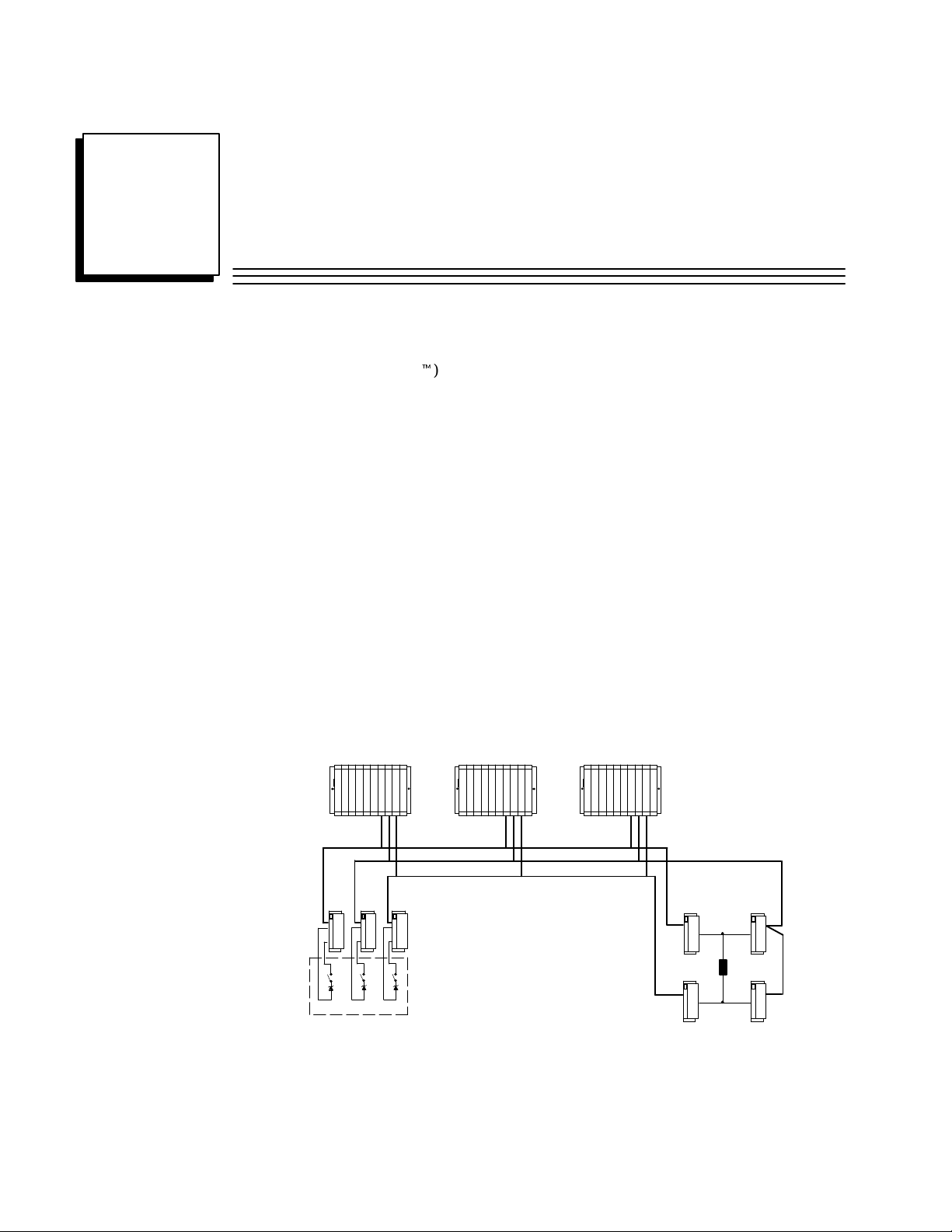
A basic GMR system consists of groups of Genius blocks gathering data from multiple or single
sensors, multiple PLCs running the same application program, and groups of Genius blocks
controlling shared output loads. Communications between the blocks and PLCs and among the
PLCs is provided by the Genius bus.
Triple PLCs
Triple Genius Busses
GFK-0787B
Load
Triple Input Sensors
GMR provides great configuration flexibility. A system can include 1, 2, or 3 PLCs. There can be just one
I/O subsystem, as represented above, or more than one. Each I/O subsystem can include 1, 2, or 3 busses.
A bus can serve up to a total of 32 devices (I/O blocks, P LCs , a nd a Ha nd - h eld Monitor ) . T he system c an
include both non-redundant I/O blocks and individual non-redundant points on redundant blocks.
1-1
Page 9
1
Series 90-70 PLC CPU
IC697CPU788
DA
Series 90-70 PLC CPU
IC697CPU788
DA
Components of a GMR System
GMR Software
GMR software version 2.06 (catalog number IC641SWP714B) provided on diskette
consists of:
H
Easy-to-use GMR configuration software.
H
GMR system software, which automatically processes, monitors, and tests redundant I/O.
H
A download utility for updating programs in systems with SNP multidrop communications.
Series 90-70 PLCs
Two models of the Series 90-70 PLC CPU support GMR, CPU 788 and CPU 789. If the
GMR system includes either two or three PLC CPUs, they must be the same model.
Each PLC requires one to three Bus Controllers per bus. Minimum suffixes for GMR
version 2.06 are:
CPUs and Bus Controllers Catalog Number Minimum Suffix
IC697CPU789
Series 90-70 PLC CPU Memory IC697BEM735 D
Series 90-70 Bus Controller IC697BEM731 N
DA
Genius I/O Blocks
H
The following standard Genius blocks are supported by the GMR system. These
blocks contain GMR modifications for version 2.06 beginning with the “minimum
suffix” listed:
Block Type Catalog Number Minimum Suffix
24/48 VDC 16-Circuit Source block IC660BBD020 M
24/48 VDC 16-Circuit Sink block IC660BBD021 M
12/24 VDC 32-Circuit Source block IC660BBD024 N
5/12/24 VDC 32-Circuit Sink block IC660BBD025 N
Analog, R TD, and Thermocouple blocks no specific suffix required
H
Other types of Genius blocks can be used as non-redundant blocks in the same
system.
Additional Items
H
“SPECIAL SAFETY SYSTEM” red I/O block labels (package of 20 of the same type)
are available: IC660SLA020, A021, A023, A024, A026, A100, A101, A103, A104, A106,
D020, D021, D024, D025. These numbers correspond to the numbers of the blocks.
For example, order label IC660SLA021 for block IC660BBA021.
H
Logicmaster 90-70 Software: release 4.02 or later.
H
Hand–held Monitor (optional): IC660HHM501H (version 4.5) or later.
H
SNP Programming Cable and RS 232/RS 485 adapter . (IC690A CC901)
H
Multidrop Cable (IC690CBL714) (Two required for connecting 3 CPUs.)
1-2 GeniustModular Redundancy Flexible Triple Modular Redundant (TMR) System
Incompatible Products
H
Graphics Display System (GDS): GMR is incompatible with Cimplicity 70 GDS.
User’s Manual – March 1995
GFK-0787B
Page 10

Series 90-70 PLCs
A GMR system normally consists of one to three identical CPUs running identical
application software. Each CPU is connected to the same input and output subsystems.
Each CPU receives all inputs and performs voting for discrete inputs and mid-value
selection for analog inputs. Each CPU computes the required outputs as a function of the
inputs and the application program logic.
Inter-processor Communications
The PLCs exchange initialization data at startup, then operate asynchronously. They
communicate regularly using Global Data. Each Genius bus scan, each PLC broadcasts up to
64 words of Global Data. This includes 8 words of system information. An additional 56
words of Global Data are available for use by the application program. Redundancy is also
built into Global Data communications. Each message is sent twice, using different busses.
The PLCs may also be joined in a multidrop Series Ninety Protocol (SNP) network. A host
computer on the network can be used for gathering data from the system. In addition, the
SNP network permits convenient program updates using the Logicmaster 90 programming
software and the Program Download utility included on the GMR software diskette.
1
PLC A
C
P
U
All other normal Series 90-70 communications interfaces are also available. If required
for the application, the host software should collect data from each CPU and perform
the necessary voting.
C
P
U
Multidrop Cable
RS–232/422
Converter
Multidrop cable is catalog number
IC690CBL714 (1 cable). Two cables
are needed for 3 CPUs.
PLC CPLC B
C
P
U
1-3GFK-0787B Chapter 1 Introduction
Page 11
1
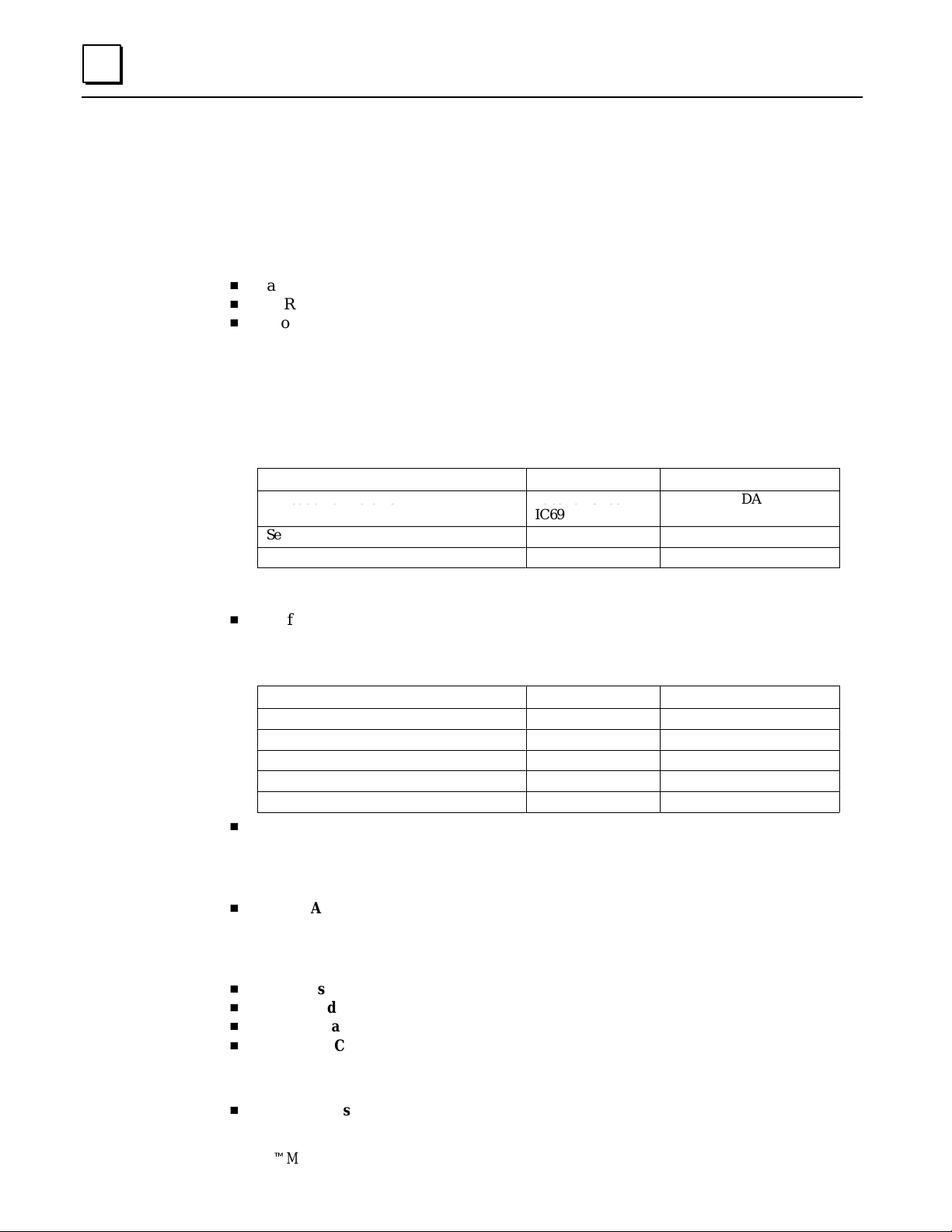
Busses and Bus Controllers
In a GMR system, there can be one to three bus controllers per bus, per PLC. Larger systems
may require more than one I/O subsystem. For example, the GMR system represented below
has two I/O subsystems for a total of six independent Genius busses and 18 bus controllers.
PLC A PLC CPLC B
ABCABC
Bus A
I/O Sub–
system
I/O Sub–
system
Each Genius bus uses a single twinax cable over distances of up to 7500 feet and data
rates of up to 153.6K baud.
Each PLC may have up to 31 Genius bus controllers, in multiple racks.
Bus B
Bus C
Bus A
Bus B
Bus C
ABCABC ABCABC
Additional Bus Controllers for Communications
The Genius busses that support GMR input/output groups are also used for internal
communications between PLCs, as explained on the previous page. They should not be
used for datagram communications. Separate busses for communications can be used for
datagrams or additional global data in the application program.
The Bus baud rate should be selected on the basis of the calculations in the Genius I/O
System and Communications User’s Manual (GFK-90486). For correct autotesting in a GMR
system, the Genius bus scan time should not be be more than 60mS.
1-4 GeniustModular Redundancy Flexible Triple Modular Redundant (TMR) System
User’s Manual – March 1995
GFK-0787B
Page 12
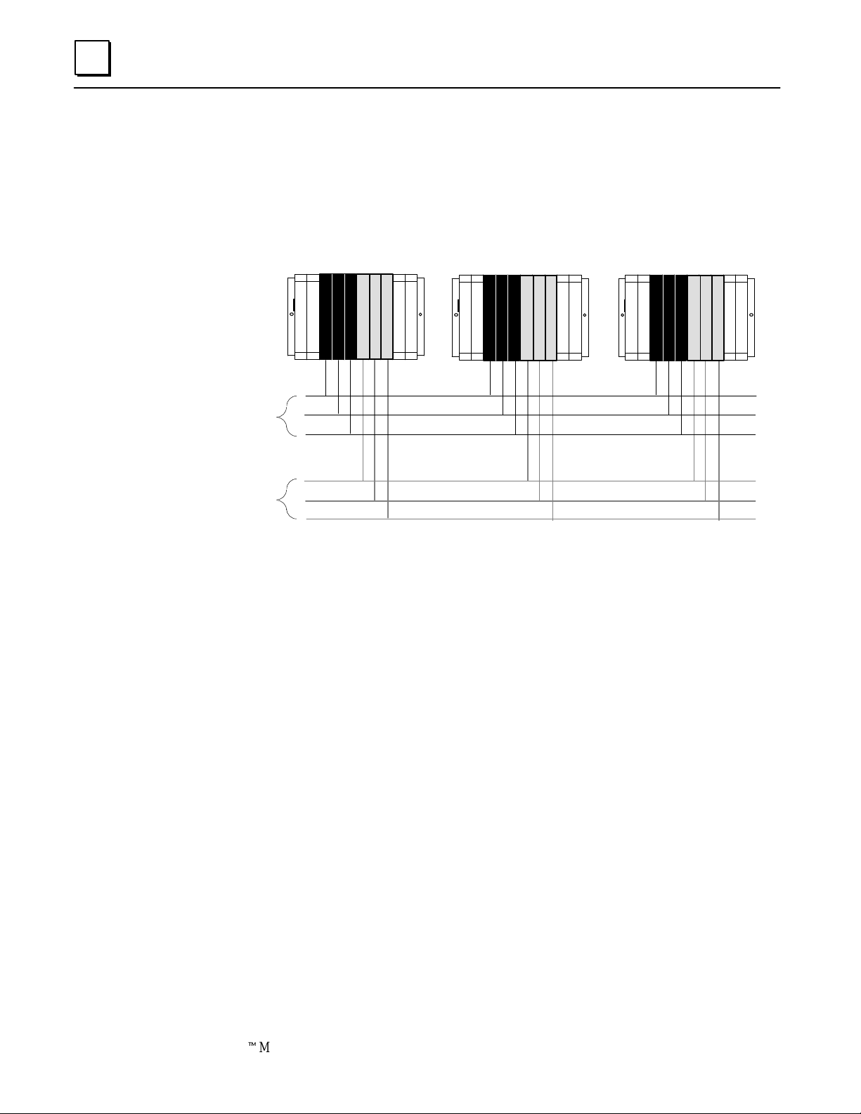
Operation Overview
Genius Modular Redundancy has been developed for use in systems that have static or nearly
static I/O under normal operating conditions. The system may have:
H
Normally-on inputs with normally-energized outputs, as in emergency shutdown systems.
H
Normally-off inputs with normally-deenergized outputs, as in fire and gas detection
systems.
Genius Modular Redundancy provides:
H
high degree of self-test and monitoring with diagnostics
H
fault tolerance.
H
support for centralized or fully distributed systems.
H
Scalable voting: 2-out-of-3, 2-out-of-2, 1-out-of-2, or simplex.
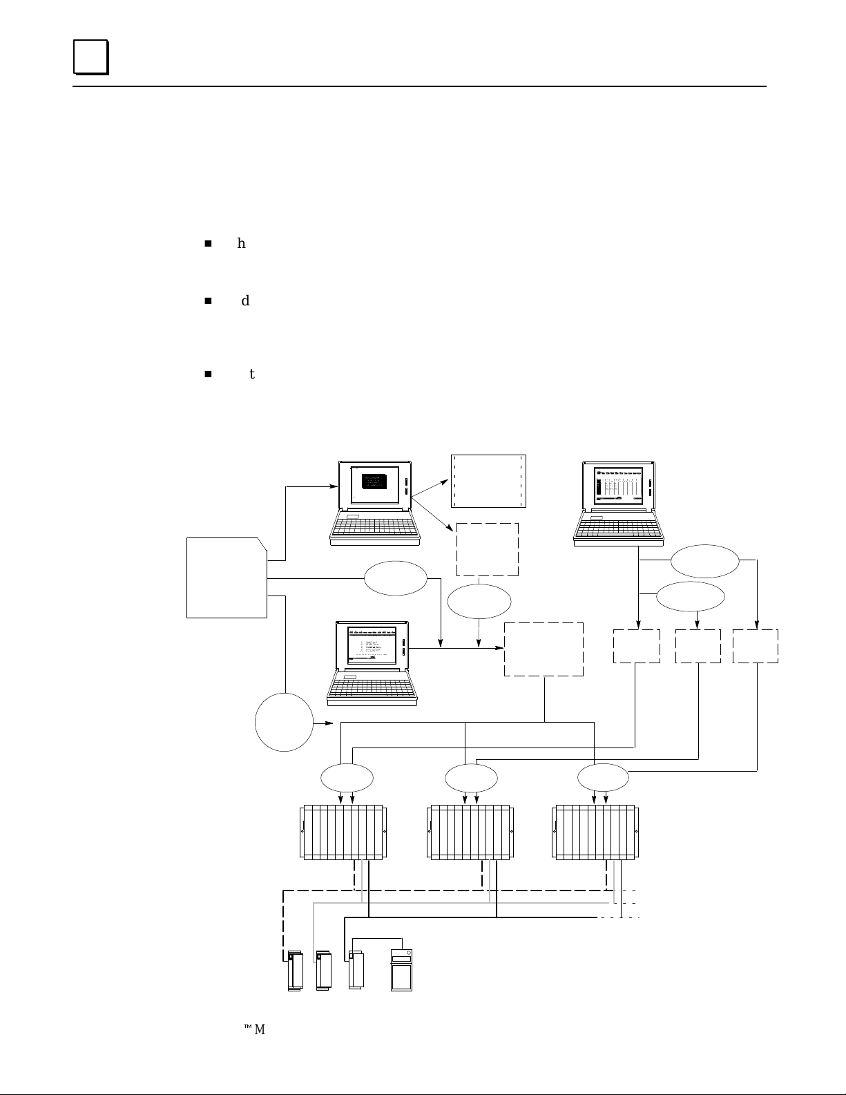
The example that follows illustrates how the GMR input subsystem, PLC subsystem, and
output subsystem combine to provide a high-availability , high-reliability system.
1
PLC A PLC CPLC B
Input Subsystem
PLC Subsystem
Load
Output Subsystem
1-5GFK-0787B Chapter 1 Introduction
Page 13
1
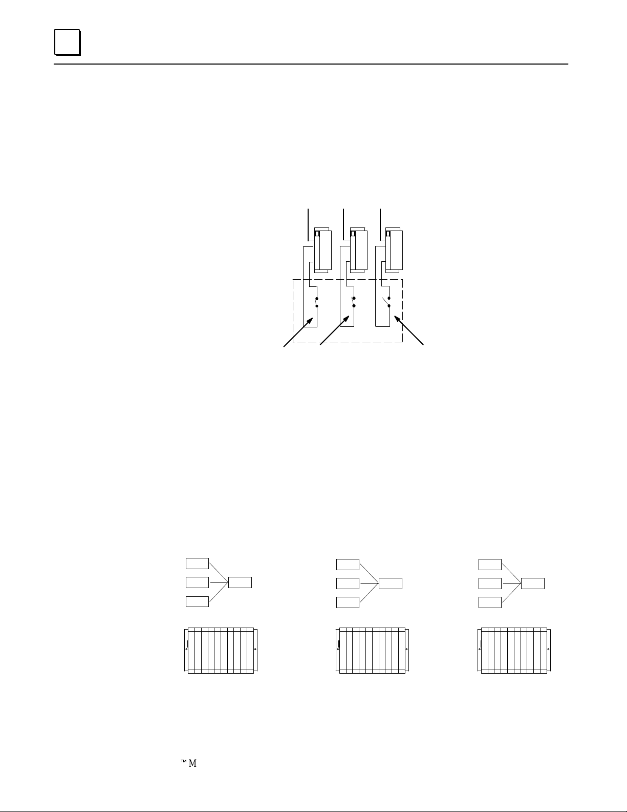
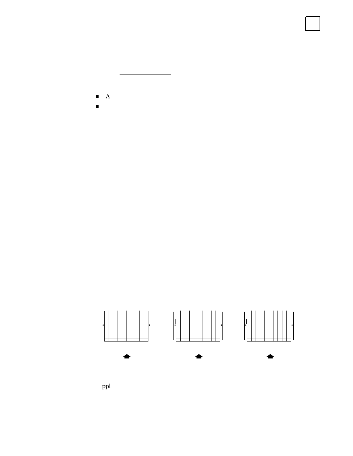
Input Subsystem
In a GMR system, the basic elements of an input subsystem are single or triple sensors
connected to triple Genius blocks. Each block is on a different communications bus
(shown below as A, B, and C).
For this example, there are triple input sensors which are normally-on. However, one of
these input sensors is off:
ABC
Closed (1)
Open (0)
Each PLC in the example system votes on the input data received from these three
sensors as summarized below. For a more detailed description of input processing, see
chapter 2.
PLC Subsystem: Voting on Input Data
The example system uses three PLCs. Each PLC receives corresponding inputs from all
three blocks in the input group.
The GMR software in each PLC automatically votes on the input data and provides the
voted input to the application program (the program can also access the unvoted input
data). Each of these example voted inputs represents the same input sensors.
input A
input B
input C
1
1
0
voted
input
1
input A
input B
input C
1
1
0
voted
input
1
input A
input B
input C
1
1
0
voted
input
1
PLC A PLC CPLC B
If an input is faulty, the PLC(s) follow a configurable, predetermined voting scheme
based on the remaining input data.
1-6 GeniustModular Redundancy Flexible Triple Modular Redundant (TMR) System
User’s Manual – March 1995
GFK-0787B
Page 14
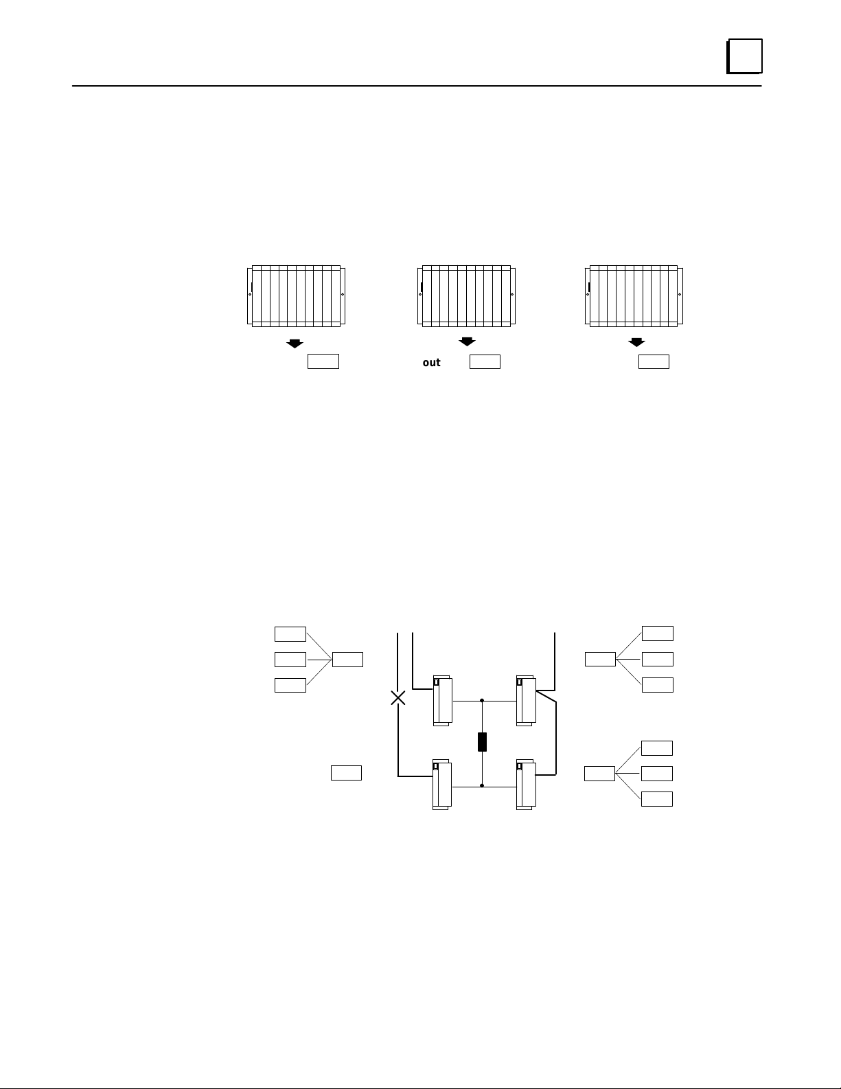
PLC Subsystem: Providing Output Data
Running the same application program, each PLC (referred to here by Genius Bus
Controller (GBC) serial bus addresses: 31, 30, and 29) processes the voted input data and
produces appropriate outputs. Because each of the three PLCs is running the same
program, they produce three copies of the same output data.
Each PLC then sends this triplicated output data on the bus.
PLC A PLC CPLC B
GBC 31
GBC 31
GBC 31
GBC 30
GBC 30
GBC 30
GBC 29
GBC 29
GBC 29
1
b
output 1
b
output 1 output 1
b
Output Subsystem
The basic element of an output subsystem is the output group. Each block in the group
has the same reference address in the application program, so each block receives the
same output data.
The output group votes on the three outputs and uses the result as the physical output.
In this example, communications are lost on bus C. Upon losing communications, the
block on bus C follows its configuration instructions, which are to default its outputs to 0.
However, the remaining blocks in the group continue to receive valid output data from
all three PLCs over busses A and B, and the actual state of the output load is controlled
properly. The loss of block or loss of bus diagnostic would be recorded, providing an aid
to troubleshooting and annunciating the problem.
C
output 31
output 30
output 29
1
1
1
voted
output
1
default
output
0
AB
AB
Load
CD
voted
output
1 output 30
voted
output
1
1
1
1
1
1
1
output 31
output 29
output 31
output 30
output 29
In a 4-block output group, each field output is supported by two Genius source outputs
connected in parallel on one side of the actuator and two Genius sink outputs connected
in parallel on the other. Each block in the group receives outputs from each of the three
separate processors.
Automatic System Test
Optional autotest routines test the complete system from input modules through to
output modules, including failures in the I/O wiring. Autotesting does not affect the
normal state of field devices.
1-7GFK-0787B Chapter 1 Introduction
Page 15

1
Genius I/O Blocks
Inputs and outputs in a GMR system are provided by Genius I/O blocks. Some types of
Genius blocks are now enhanced for GMR operation. In addition, these and other types
of blocks can be included in a GMR system as “ non-voted” blocks. Non-voted blocks are
individual blocks that are present on GMR busses in the system; they are not part of any
GMR input group or output group. They are included in the GMR configuration and
they may be autotested.
Discrete Blocks
All types of discrete blocks can be used as non-voted blocks in a GMR system.
The discrete blocks listed on page 1-2 are standard Genius blocks that are now
enhanced to include GMR functions. These blocks can be used in either GMR or
non-GMR systems. When configured for GMR operation (only), they perform output voting,
support GMR autotesting, and provide diagnostic reports to up to three PLCs. In
addition, certain of their operating parameters are changed when they are in GMR
mode.
Analog, RTD, and Thermocouple Blocks
Analog blocks can be included in the GMR configuration and used in GMR input groups,
as either voted or non-voted inputs. However , analog blocks in GMR input groups are
not autotested by the GMR software.
Analog blocks do not provide output voting, so they cannot be used in GMR output
block groups. However, they can be used as non-voted blocks in a GMR system, and
support standard Hot Standby Redundancy.
Analog, RTD, and Thermocouple blocks operate the same way in either GMR or non-GMR
systems. No specific versions of these blocks are required for GMR use.
I/O Block Summary
The following table summarizes how different types of blocks can be used in a GMR system.
Basic Block Types Can be GMR
Input Block
24/48 VDC 16-Circuit Source block
24/48 VDC 16-Circuit Sink block
12/24 VDC 32-Circuit Source block
5/12/24 VDC 32-Circuit Sink block
Any other discrete block no no yes no yes
Analog, R TD, and Thermocouple
blocks
High-speed Counter block no no no no yes
P ower Trac block no no no no yes
yes yes yes yes yes
yes no yes no yes
Can be GMR
Output Block
Can be
“ non-voted”
GMR block
Can be
A utotested
Can be
non-GMR
block
1-8 GeniustModular Redundancy Flexible Triple Modular Redundant (TMR) System
User’s Manual – March 1995
GFK-0787B
Page 16
Number of
Voted GMR
Number
of V oted
1
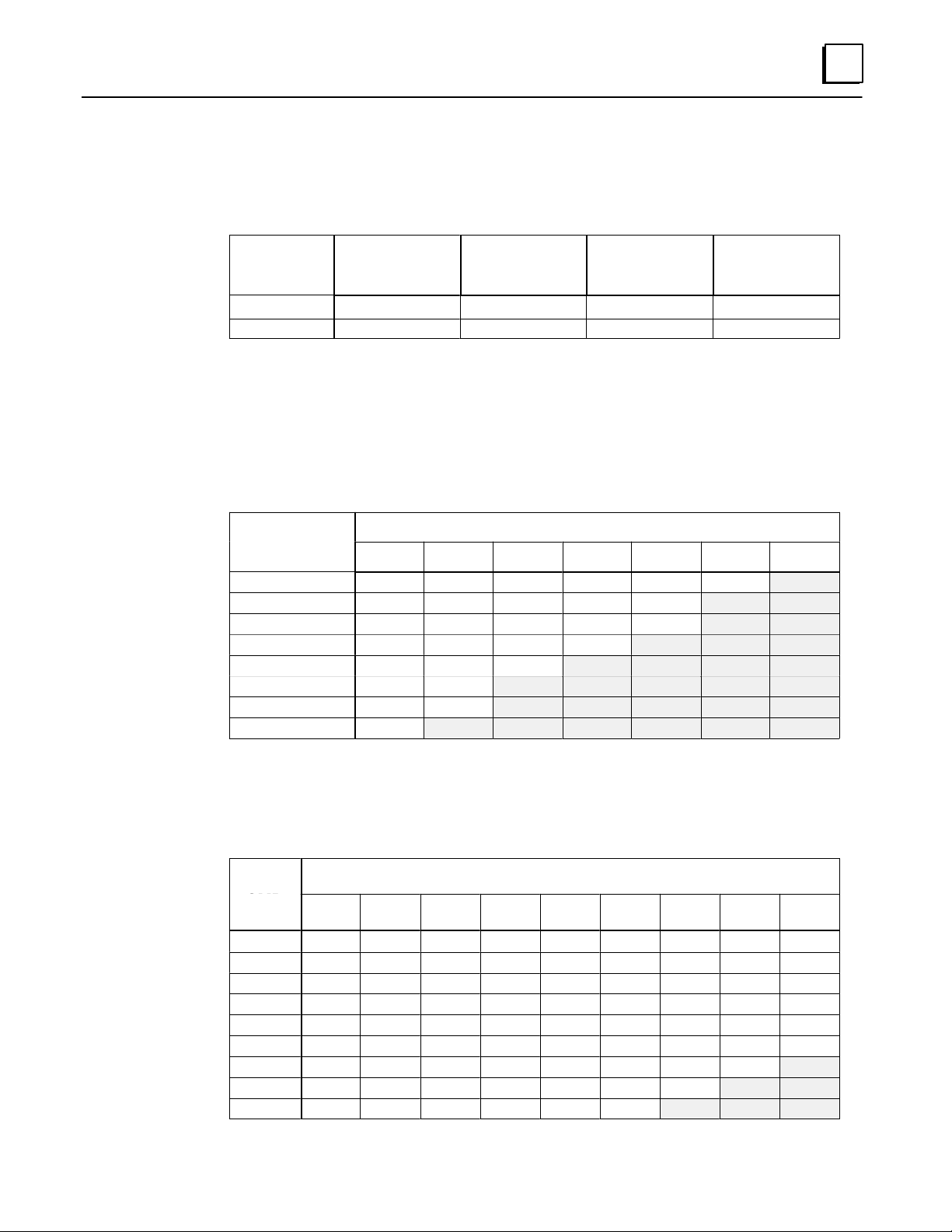
Number of I/O Points in a GMR System
The I/O capacity of the system depends on whether the CPU is a model 788 or model 789. For
most applications, these limits will not be reached. If you need help estimating I/O sizes for a
large application, contact GE Fanuc at 1-800-828-5747.
CPU Model Total Discrete
Physical I/O
788 352 112 80 100
798
Non-GMR I/O: Non-GMR I/O is I/O that is not included in the GMR configuration. The
amount of non-GMR I/O that can be used depends on the amount of GMR I/O present and
the CPU memory capacity. The tables below show how much memory is available for
non-GMR I/O (main part of tables) for given numbers of GMR inputs and GMR outputs. In
the equations, the GMR Inputs and GMR Outputs are the actual number of I/O configured
with the programming software.
12288 2048 2048 4096
Maximum
Number of
V oted Inputs
Maximum
Number of
Voted Outputs
Maximum Total
Voted I//O
Number of Non-GMR I/O Available for the 788 CPU
Number of Redundant GMR Outputs
Inputs
0 352 288 224 160 96 32
16
32
48
64
80
96
112
0 16 32 48 64 80 96
304 240 176 112 48
256 192 128 64 0
208 144 80 16
160 96 32
112 48
64 0
16
Number of Non-GMR I/O Available for the 789 CPU
These numbers are determined by the limits of physical I/O based on the Logicmaster
configuration and table size limitations based on the manner in which GMR maps I/O into
multiple locations in the I/O tables (this is explained in chapter 4).
of Voted
GMR
Inputs
0
256
512
768
1024
1280
1536
1792
2048
0 256 512 768 1024 1280 1536 1792 2048
12288 11264 10240 9216 8192 7168 6144 5120 4096
11264 10496 9472 8448 7424 6400 5376 4352 3328
10240 9728 8704 7680 6656 5632 4608 3584 2560
9216 8960 7936 6912 5888 4864 3840 2816 1792
8192 7936 7168 6144 5120 4096 3072 2048 1024
7168 6912 6400 5376 4352 3328 2304 1280 256
6144 5888 5632 4608 3584 2560 1536 512
5120 4864 4608 3840 2816 1792 768
4096 3840 3584 3072 2048 1024
Number of Redundant GMR Outputs
1-9GFK-0787B Chapter 1 Introduction
Page 17
1
Configuration and Programming
The GMR Software
The GMR software consists of:
H
The GMR configuration software file, CONFIG.EXE. This file, which runs under DOS, is
used to enter the system parameters that will be used by the GMR system software. When
the GMR configuration is completed, it produces a Program Block named G_M_R10.
H
A directory named GMRxxyy containing the GMR system software files, to which
the application program will be added. In the directory name GMRxxyy, xx is two
digits representing the major revision level of the GMR software. The last two digits
(yy) represent the minor software revision level.
H
A “teach” file named KEY0.DEF for use in future application program updates.
Subsequent chapters of this book explain configuration steps and programming
guidelines for a GMR system. The basic steps are illustrated below.
GMR
Diskette
CONFIG.EXE
GMRxxyy
KEY0.DEF
future
program
updates
GMR CONFIGURATION
LM90
Copy Folder
LM90 PROGRAMMING
LM90
Store
GMR
Configuration
Printout
G_M_R10
Program
Block
LM90
Librarian
LM90
Store
The
Application
Program
LM90 CONFIGURATION
Copy Folder
LM90
Store
LM90
Copy Folder
LM90
CONFIGBCONFIGA
CONFIGC
PLC A
PLC B PLC C
I/O Block Configuration with
Hand-held Monitor
1-10 GeniustModular Redundancy Flexible Triple Modular Redundant (TMR) System
User’s Manual – March 1995
GFK-0787B
Page 18
The Basic Steps of Configuration and Programming
1. Use the GMR configuration software to complete the GMR configuration. There is
only one GMR configuration needed for the system. GMR configuration sets up the
parameters that will be used by the system, including refer ence addr esses. The GMR
configuration software produces:
H
A printout of the GMR Configuration.
H
A program block named G_M_R10. This is later added to the application program.
2. Using the LM90 configuration software, create a Logicmaster configuration for
each PLC. The easiest way to do that is to:
A. Create a Program Folder for PLC A. W ith the GMR configuration printout as a
reference, complete its Logicmaster configuration.
B. Use the Copy Folder feature of the Logicmaster 90 programming software to
copy the configuration of PLC A to additional folders for PLC B and PLC C.
C. Edit the configurations for PLC B and PLC C as necessary .
3. Using a Hand-held Monitor , complete the Genius block configuration. Genius block
configuration sets up the operating characteristics of each block in the GMR system.
1
4. Using the Logicmaster 90 programming software, create the application program.
While there can be up to three PLCs in a GMR system, each of which has a slightly
different configuration, there is normally only one application program.
A. Using Logicmaster 90, copy the folder named GMRxxyy (for example,
GMR0101) from the GMR software diskette to a program folder with your
application program name (such as GMRPROG).
B. Using Logicmaster 90, add program block G_M_R10 (created with the
configuration utility) to the application program folder.
C. Create or add the application program logic in this folder.
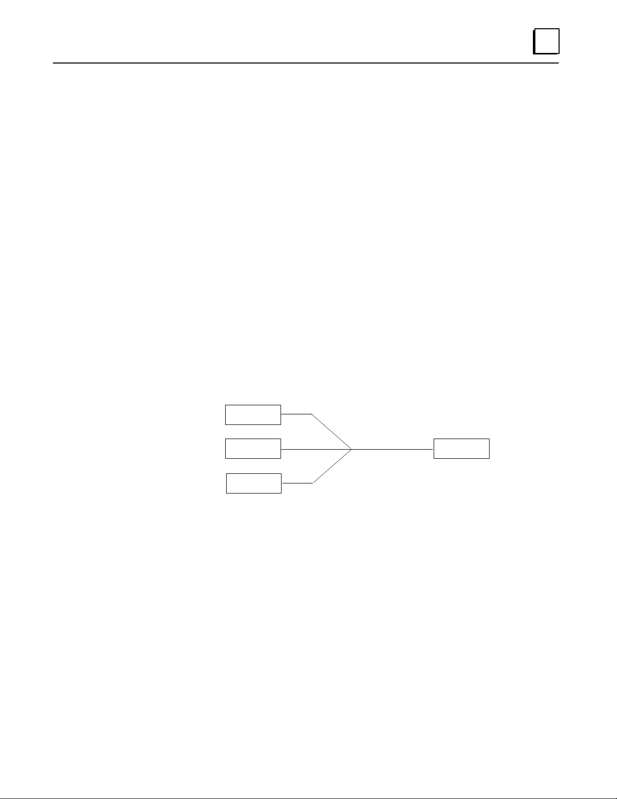
5. After completing the application program and the configuration(s), store them to
the PLCs. As explained above, all redundant PLCs in the GMR system normally use
the same application program, but different configurations:
PLC A
PLC B PLC C
yyy
Program: GMRPROG
Configuration: CONFIGA
Supplying the configuration and program as separate files, as shown, makes it easier
to perform program updates in the future.
The GMR Configuration Software allows the system to be set up for online program
changes. Online changes are intended for system debug and commissioning.
Program: GMRPROG
Configuration: CONFIGB
Program: GMRPROG
Configuration: CONFIGC
1-11GFK-0787B Chapter 1 Introduction
Page 19

Chapter 2 Input Subsystem
section level 1 1
2
This chapter provides information about the inputs to a GMR system.
H
H
H
H
figure bi level 1
table_big level 1
Overview
GMR Input Groups
Non-Voted I/O in the Input Subsystem
Discrete Inputs
h
Types of Blocks in the Input Subsystem
h
Discrete Input Processing
h
Discrepancy Reporting for GMR Inputs
h
Input Autotest for GMR Inputs
h
Line Monitoring for Discrete Inputs
h
Manual Input Controls
H
Analog Inputs
h
Voted Analog Inputs
h
Analog Discrepancy Reporting
h
Non-Voted Analog Inputs in GMR Input Groups
h
Non-GMR Analog Blocks
GFK-0787B
2-1
Page 20
2
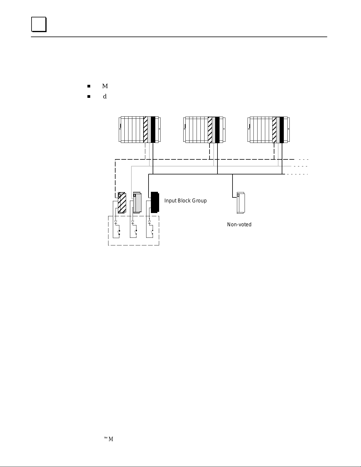
Overview
The input subsystem is the part of a GMR system that gathers input data. It may consist of:
H
GMR Input groups of 1 to 3 discrete or analog blocks
H
Individual non-voted discrete and analog blocks
The following illustration represents basic elements of an input subsystem.
Triple PLCs
Triple Genius Busses
Input Block Group
Non-voted
(non-redundant)
ABC
Triple Input Sensors
GMR blocks are arranged in “groups” of 1, 2, or 3 blocks. Within a group, all the blocks must be
the same type. The input group shown above consists of three Genius blocks. Each has its own
input sensors monitoring the same parts of the applic ati on process. Each block sends the input
data from its sensors to three Series 90-70 PLCs. F or si mpl i fication, the illus trati on only shows one
input circuit on each block. However , each group can serve multiple GMR inputs. In additi on,
circuits that are not needed for GMR inputs can be used for non-voted inputs or outputs.
Genius blocks broadcast their inputs. So each block’s input data is received by all PLCs on the
bus. The GMR system software in each PLC then performs input voting and provides the results
to its application program. If all input data is not availabl e, the software follows a configured
voting adaptation scheme. Details of both discrete and analog input voting are in the PLC
chapter.
In addition to the diagnostics capabilities of the Series 90-70 PLC and Genius I/O blocks,
the GMR system provides autotesting and discrepancy reporting for GMR inputs.
Input Block
Genius blocks configured for GMR operation automatically generate three copies of
their standard Genius fault report messages. They send one copy to the PLC Bus
Controller configured with serial bus address 31, one to 30, and one to 29. So all of the
GMR PLCs are able to monitor the blocks for Genius diagnostics.
2-2 GeniustModular Redundancy Flexible Triple Modular Redundant (TMR) System
User’s Manual – March 1995
GFK-0787B
Page 21
GMR Input Groups
The configuration can include as many as 128 16-circuit voted discrete and 256 four-input analog
input groups. (The actual I/O capacity of the system depends on the CPU type. See page 1-9).
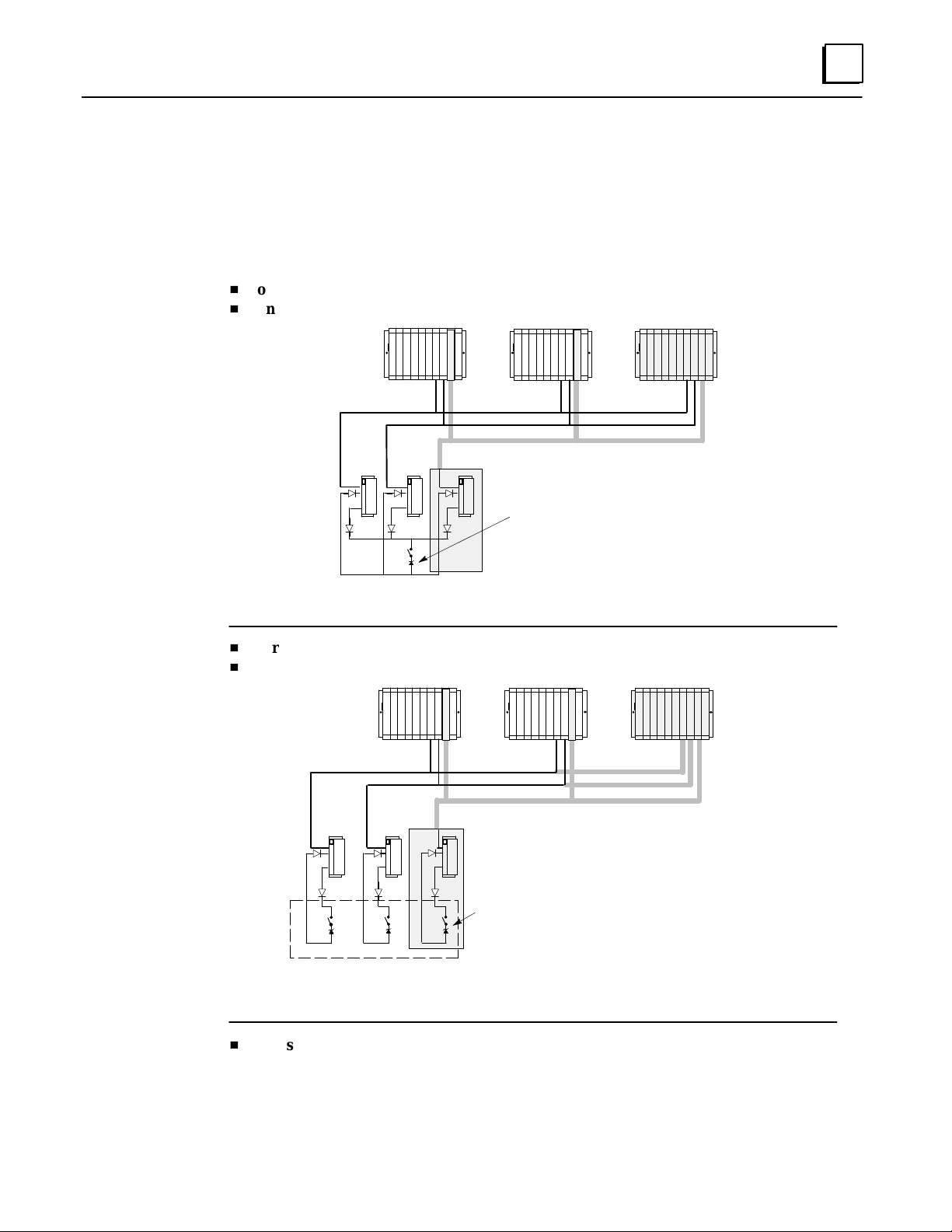
In an system that has normally-energized discrete inputs, the following combinations of
sensors and Genius inputs can be used with Genius Modular Redundancy.
H
one sensor to three Genius inputs, three busses, three PLCs
H
one sensor to two Genius inputs, two busses, two PLCs
2
Triple PLCs
Triple Genius Busses
Shaded items omitted
for duplex operation
Optional Zener
diode for line
monitoring
One Input Sensor
H
three sensors to three Genius inputs, three busses, three PLCs
H
two sensors to two Genius inputs, two busses, two PLCs
Triple PLCs
Triple Genius Busses
Shaded items omitted
for duplex operation
Optional Zener
diodes for line
monitoring
Triple Input Sensors
H
one sensor to one Genius input
Single blocks can be configured as non-voted GMR blocks, allowing them to take
advantage of the GMR autotest feature. Both discrete and analog blocks can be used;
however, analog blocks cannot be autotested.
2-3GFK-0787B Chapter 2 Input Subsystem
Page 22
2
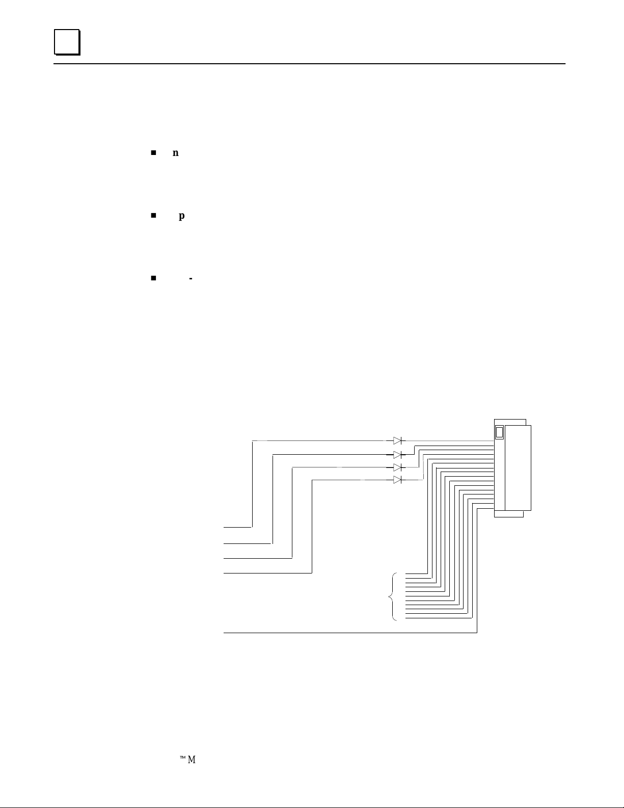
Non-Voted I/O in the Input Subsystem
The input subsystem can also include three types of non-voted inputs:
H
Inputs from single-block (simple x) GMR input groups
Individual blocks can be included in the GMR configuration as “simplex groups”,
and can utilize the GMR features such as autotesting. Inputs from simplex blocks are
placed into the area of the Input Table used for GMR inputs.
H
Inputs from non-GMR I/O blocks
“Non-voted” blocks are individual blocks that are present on a GMR bus and are
included in the GMR configuration. However, their inputs are not voted on by the
PLC(s), and are located in a different area of the Input Table.
H
Non-voted points on individual blocks in a multiple-block GMR input group
Non-voted I/O points may be placed within a voted input group, to take advantage
of unused circuits. These extra circuits can be used as either inputs or outputs. If the
group utilizes GMR autotesting of inputs, circuit 16 on each block, which is required
for autotest, cannot be used for non-GMR I/O.
Example: a discrete input group consisting of three 16-circuit blocks has only four
voted inputs. That leaves circuits 5 through 15 on each block for use as non-GMR
inputs or outputs. Circuit 16 is used for the autotest feature.
Block A
1st GMR input
2nd GMR input
3rd GMR input
4th GMR input
Can be used as
non-GMR inputs
and outputs
GMR Autotest
Blocks B and C are the same
Individual input points used in this way can be autotested if autotesting is set up as
part of their GMR configuration.
2-4 GeniustModular Redundancy Flexible Triple Modular Redundant (TMR) System
User’s Manual – March 1995
GFK-0787B
Page 23

Discr ete Inputs
Types of Blocks in the Input Subsystem
The following discrete block versions can be configured for GMR version 2.06 operation
and used as GMR input blocks:
All types of Genius blocks can be used as non-GMR blocks in a GMR system.
Note that the GMR Input Autotest feature requires point 16, so if the system uses Input
Autotest, point 16 is not available as an I/O point for the application (leaving either 15 or 31
points available on the blocks listed above).
24/48 VDC 16-Circuit Source block: IC660BBD020M or later
24/48 VDC 16-Circuit Sink block: IC660BBD021M or later
12/24 VDC 32-Circuit Source block: IC660BBD024N or later
5/12/24 VDC 32-Circuit Sink block: IC660BBD025N or later
2
Discrete Input Processing
Discrete input processing is handled in each PLC, by the GMR system software. The
manner in which inputs are handled depends upon whether a block is included in the
GMR configuration, and if it is, upon whether it is part of a 3-block, 2-block, or 1-block
group. Input processing by the PLC is explained in detail in the PLC chapter. In general,
the GMR system software compares input data from all corresponding inputs (3, 2, or 1)
for each point, and provides a voted input result for use by the application program. If
all the input data is not available, the GMR system software follows a configured voting
adaptation scheme. The application program can also access the original, unvoted input
data, along with any non-GMR inputs that have been included in the input subsystem.
Field Input Data
Input A
Input B
Input C
0
0
1
GMR Software Performs
2 out of 3 V oting
Single Input Provided to Applica-
tion Logic
0
Discrepancy Reporting for GMR Inputs
For GMR inputs, if there is a discrepancy between the original input data for an input
and the voted input state, the GMR software automatically places a message in the I/O
Fault Table, where it is available to the Logicmaster 90 software and the application
program logic. This is also described in more detail in the PLC chapter. Fault bits are also
set for input discrepancies. These fault bits are available for use in the application
program, for further annunciation or corrective action.
Discrepant signals are filtered for a configurable time period, to eliminate transient
discrepancies caused by timing differences.
2-5GFK-0787B Chapter 2 Input Subsystem
Page 24
2
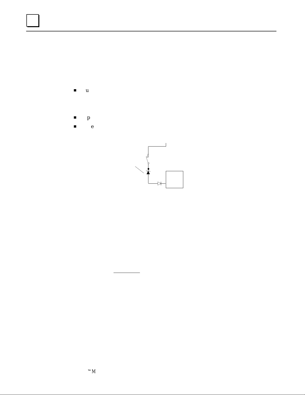
Input Autotest for GMR Inputs
During GMR configuration, input autotesting can be individually turned on or off for each
input in an input group. The GMR software will automatical l y test the selected inputs for the
ability to reach the alarm state. The ability to diagnose short circuits on inputs depends on
whether the circuit is set up as a bistate or tristate input, and on whether the block itself is
configured for GMR mode (using the Hand-held Monitor).
H
Autotesting checks the ability of the input electronics to recognize both the On and
the Off state. During each Input Autotest, some inputs are forced to the Off state by
de-energizing the power feed output, and some are forced to the On state via the
Genius block electronics. See page 5-6 for more detailed information.
H
Input autotesting also detects circuit-to-circuit shorts.
H
Note: blocking diodes are required to use the Input Autotest feature. These diodes
are in addition to a Zener diode that may be added for line monitoring.
+24V
Optional Zener diode
for line monitoring
Source
Genius
Block
See page 5-6 for more detailed information about input autotesting. Also see pages 8-3
through 8-9 for Autotest wiring information.
Calculating Voltage Drops on Tristate Inputs
It is important to consider the field wiring runs required for devices configured as
tristate inputs. Devices that are powered by 24V DC will have a voltage-reducing
component inserted at the field device to provide an input threshold range for three
states. The table on the next page shows appropriate ranges. Wiring r uns can reduce the
voltage at the input block terminal further, to an inoperable level, depending on the
length, conductor, and gauge. Isolation diodes placed before the terminal on the input
will also drop the voltage.
Most applications do not have limitations created by these factors. However, to ensure
that all input state operations are indicated correctly, calculations should include the field
signal voltage, the wire resistance times the length and the voltage drop in any barriers
or isolation devices, to determine the actual voltage present at the input terminal.
Additional information about input blocks is located in the Genius I/O Discrete and Analog
Blocks User’s Manual (GEK-90486-2).
2-6 GeniustModular Redundancy Flexible Triple Modular Redundant (TMR) System
User’s Manual – March 1995
GFK-0787B
Page 25
Source Blocks
tristate inputs
Source Blocks
tristate inputs
bi-state inputs
bi-state inputs
Sink Blocks
tristate inputs
Sink Blocks
tristate inputs
bi-state inputs
bi-state inputs
2
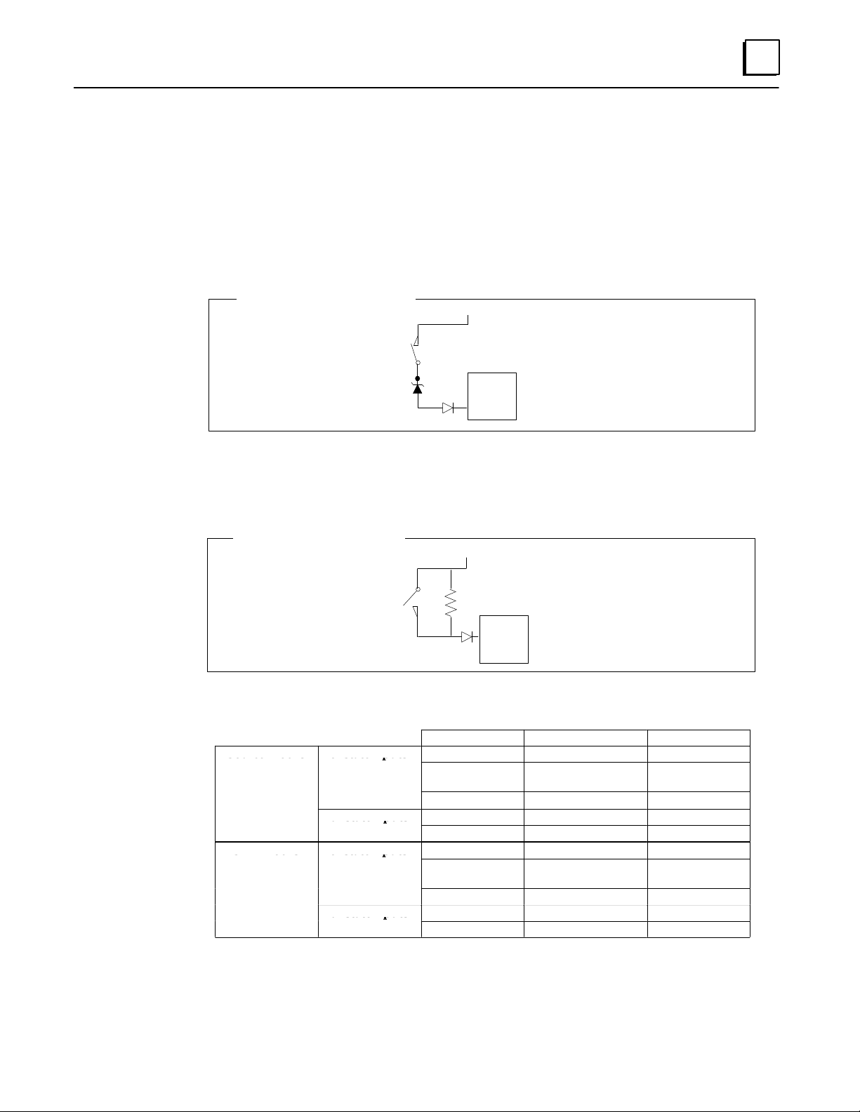
Line Monitoring for Discrete Inputs
Normally-closed inputs on GMR -configured blocks can be monitored for short circuit
faults. Normally-open inputs on blocks which are not configured in GMR mode can be
monitored for open circuit faults.
Normally-closed Inputs
For applications such as Emergency Shutdown (ESD), normally-closed inputs are generally
monitored for short circuits across the lines, since that represents a fail to danger condition
(that is: trip is not detected). In general, these inputs are powered from +24V, and a field
short to ground is interpreted as a trip condition.
Typical Normally-closed Input
Normally-open Inputs
For applications such as Fire and Gas Detection, normally-open inputs are generally
monitored for open circuits on the lines, since that represents a fail to danger condition
(that is: trip is not detected). In general, these inputs are powered from +24V, and a field
short to +24V is interpreted as a trip condition.
Typical Normally-open Input
+24V
Source
Genius
Block
+24V
Source
Genius
Block
When a block is configured (with a Hand-held Monitor) as a GMR block, its input thresholds
change to those listed below.
Input Voltage Input Status Input State
<30% V
>50% V
< Vdc–7V
dc
dc
< Vdc–4V
<30 V
dc
>50% V
<50% V
>70% V
<50% V
>70% V
dc
<4V short circuit fault 1
>7V
dc
dc
dc
dc
off 0
on 1
short circuit fault 1
off 0
on 1
on 1
off 0
on 1
off 0
Input Filter Time
For any circuit configured as a tristate input, the Input F ilter Time configured for the block
(using a Hand-held Monitor) must be at least 30mS.
2-7GFK-0787B Chapter 2 Input Subsystem
Page 26
2
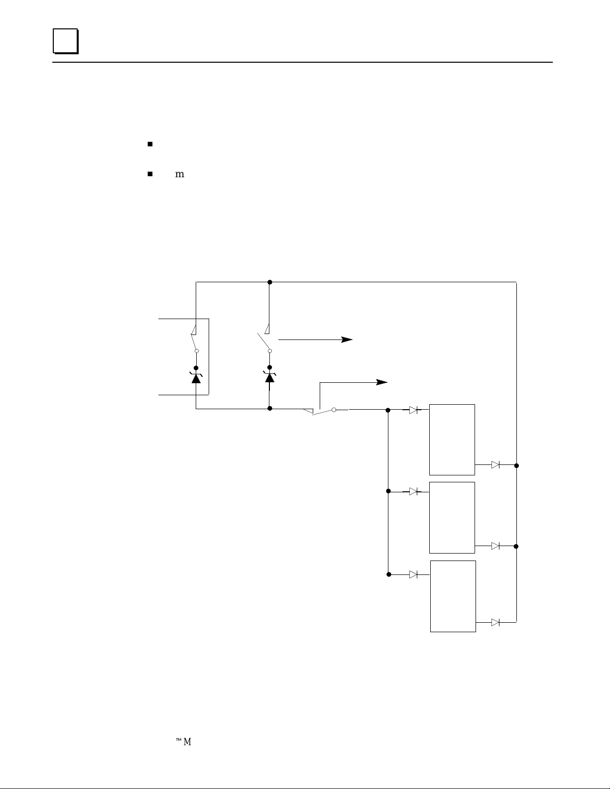
Manual Input Controls
Safety systems often use controls for manual trip and manual inhibit. The GMR autotest and
fault processing operations are unaffected by such controls.
H
A manual trip causes the input to assume the alarm condition. For example, for a
normally-energized input, the input is open circuit.
H
A manual inhibit causes the input to remain in the normal condition. F or e xample,
for a normally-energized input, the input is held high even if the device is in the Off
state.
These manual controls can be implemented either in hardware or in software.
Hardware control usually consists of switch contacts applied to the input circuit, as shown
below for a normally-energized input. Repeat contacts of the control switches are often input
into the system for reporting purposes.
Field
Circuit
System Input
Manual Inhibit
System Input
Manual Trip
point 1
Source
Genius
Block
point 16
point 1
Source
Genius
Block
point 16
point 1
Source
Genius
Block
point 16
2-8 GeniustModular Redundancy Flexible Triple Modular Redundant (TMR) System
User’s Manual – March 1995
GFK-0787B
Page 27
Analog Inputs
Like discrete blocks, analog blocks can be used in the input subsystem as members of
GMR input groups of 1 to 3 blocks, or as non-voted blocks. Also like discrete blocks,
individual circuits of analog blocks in multiple-block GMR input groups can be used as
non-voted analog inputs.
Analog blocks in GMR input groups are not autotested by the GMR software.
All of the available types of analog blocks can be used, including the Thermocouple and
RTD blocks. See the Genius I/O Discrete and Analog Blocks User’s Manual for information
about the various analog Genius blocks.
The application program can reference all analog inputs directly, whether they are
located in the non-voted analog inputs area or not.
V oted Analog Inputs
For voted analog inputs, analog blocks must be set up as 2-block or 3-block input groups.
The input values are in engineering units.
2
For a 3-block group, the GMR software compares the three corresponding inputs for
each channel and selects the intermediate value. This value is made available to the
application program. The application program can also access the original input values.
Field Input Data
Input A
Input B
Input C
For example, in the illustration above, inputs A, B, and C might represent the first
channel on each block in a three-block group. The PLC would place the selected input
value into the first voted input word for that group.
152
150
110
PLC Selects the
Intermediate Value
Single Input Provided
to Application Logic
150
Number of Input Sensors per Voted Channel
For each voted input channel in a 3-block group, either single or triple input sensors that
are compatible with the input drive requirements of the Genius blocks can be used.
Current-loop (4-20mA) devices must be converted to voltage when a single sensor is
used.
Analog Voting Adaptation
If a failure (discrepancy fault, or Genius fault) occurs, the GMR software rejects the
faulty data. Depending on the configuration of the input group, input voting may go
from three inputs to two inputs to one input, or from three inputs to two inputs to the
configured default value.
2-9GFK-0787B Chapter 2 Input Subsystem
Page 28

2
Analog Discrepancy Reporting
When the GMR software compares analog input data, it checks each channel against
discrepancy limits provided as a part of the configuration for that input group. Any
channel that varies by more than a configurable percentage from the intermediate value
is reported.
Discrepancy signals are filtered for a configurable time period, to eliminate transient
discrepancies caused by timing differences.
Non-Voted Analog Inputs in GMR Input Groups
If a system includes analog inputs that do not require redundancy, they are usually
located on individual analog blocks. However, they can also be located on channels of
blocks in a GMR analog input group that do not require redundancy. For e xample, a
group of three 6-channel analog input blocks might use only four voted inputs on each
block. That would leave inputs 5 and 6 available for connection to other sensors not
requiring voting.
Non-GMR Analog Blocks
Individual analog blocks can be used as input blocks or combination input/output blocks.
All of the operating features of these blocks are available.
Individual non-voted analog blocks can be included in the GMR configuration.
2-10 GeniustModular Redundancy Flexible Triple Modular Redundant (TMR) System
User’s Manual – March 1995
GFK-0787B
Page 29

Chapter 3 Output Subsystem
section level 1 1
3
This chapter describes GMR output subsystem.
H
H
H
figure bi level 1
table_big level 1
Overview
Types of Blocks in the Output Subsystem
GMR Output Handling
h
Output Voting
h
Duplex Default for Outputs
h
Output Forces and Overrides
h
Output Fault Reporting
H
4-Block Output Groups
h
Output Load Sharing
H
Manual Output Controls and Diagnostics
H
Redundancy Modes for Output Blocks
h
GMR Mode
h
Hot Standby Mode
GFK-0787B
3-1
Page 30
3
Overview
The output subsystem is the part of a GMR system that provides output data. It may consist of:
H
GMR Output groups of 4 discrete blocks
H
Individual non-GMR discrete and analog blocks
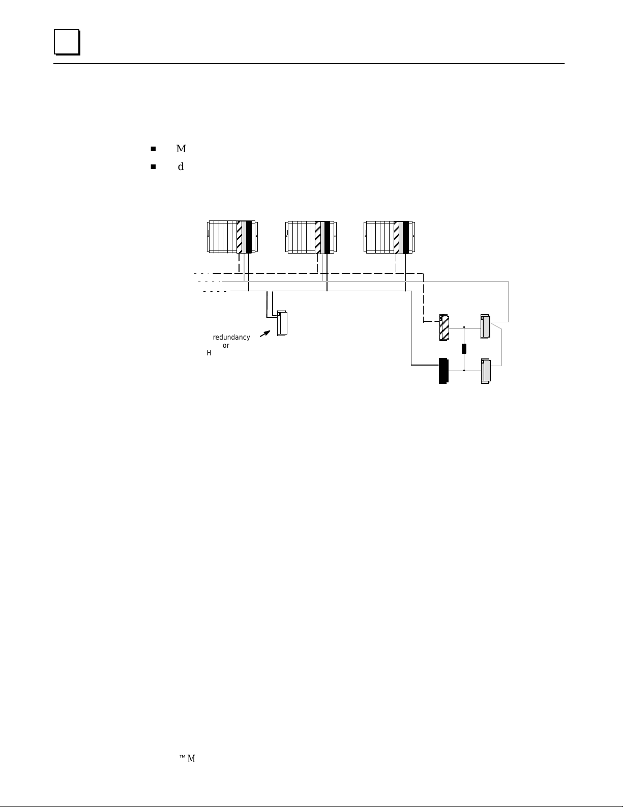
The following illustration represents basic elements of an output subsystem.
ABC
No redundancy
or
Hot Standby
or
Duplex
In a 4-block output group, each field output is supported by two Genius source outputs
connected in parallel on one side of the actuator and two Genius sink outputs connected
in parallel on the other. Each block in the group receives outputs from each of the three
separate processors. Three Genius busses are used.
Individual Genius blocks can also be connected to the system. These blocks may be
configured for either hot standby or duplex CPU redundancy if desired.
ABC ABC
A
Load
DC
4-Block Output Group
B
Types of Blocks in the Output Subsystem
The following discrete block versions can be configured for GMR operation. They will
perform output voting and autotesting when used in GMR mode:
24/48 VDC 16-Circuit Source block:
24/48 VDC 16-Circuit Sink block:
12/24 VDC 32-Circuit Source block.
5/12/24 VDC 32-Circuit Sink block:
3-2 GeniustModular Redundancy Flexible Triple Modular Redundant (TMR) System
User’s Manual – March 1995
IC660BBD020M
IC660BBD021M
IC660BBD024N
IC660BBD025N
GFK-0787B
Page 31

GMR Output Handling
Unlik e GMR input voting, which is done by the GMR software in the PLCs, output voting is
performed at the output block groups. To perform output voting, the blocks must be one of the
listed types, and they must be configured (with a Hand-held Monitor) to be in GMR mode.
Output Voting
A GMR output block group compares corresponding output data for each point as
received from each of the three PLCs. If all three PLCs are online, the data from at least
two must match. The block group sets each output load to match the state commanded
by at least two of the PLCs.
Outputs from 3 PLCs
PLC A
3
Single Output
0
Provided to
Field Device
PLC B
PLC C
If only two of the three PLCs are communicating on the bus and they send matching
output data for a point, the block group sets the output to that state.
If only two PLCs are communicating, the block group performs 2 out of 3 voting using
the data from the two online PLCs and the block’s configured duplex default state in
place of the offline PLC data.
If only one of the three bus controllers is present on the bus, the block group sets output
states to match the output data sent by that PLC.
If the Simplex Shutdown feature is enabled, a PLC will shut down if it determines that it
is the only PLC still operating. The timeout period before it shuts down is configured as
the next item. When the PLC shuts down and a block group is no longer receiving
output data, outputs will go to their default state or last state, as configured at each block
group.
If all PLCs are offline, the block group forces its outputs to the block’s configured default state.
The voted state of the output is available to the GMR system for monitoring purposes to
determine output discrepancies. However, the voted output state is not available to the
application program.
0
1
GMR Block Performs
2 out of 3 V oting
0
Duplex Default for Outputs
As mentioned, the duplex default state is used when a block determines that only two PLCs
are online. The Duplex Default state of On or Off is used by the 2 out of 3 voting algorithm
in the block group, instead of the state that would have been supplied by the third PLC.
The Duplex Default state determines whether voting will be 1 out of 2 or 2 out of 2 when
only two PLCs are providing outputs. This is explained on the next page.
3-3GFK-0787B Chapter 3 Output Subsystem
Page 32

3
The following three tables compare voting results for a block group receiving outputs
from all three PLCs with results when one of the three PLCs is offline.
Results of Block Group Voting with Three PLCs Online
For comparison, this table shows how a block group votes on outputs received from
three PLCs when all three are online. The block group doesn’t use the Duplex Default, so
it is shown as an X (don’t care).
PLC A Output
State
0 0 0 X 0
0 0 1 X 0
0 1 0 X 0
0 1 1 X 1
1 0 0 X 0
1 0 1 X 1
1 1 0 X 1
1 1 1 X 1
PLC B Output
State
PLC C Output
State
Duple x Default
Setting in Block
Output State
Results of Block Group Voting with Two PLCs Online, and Duplex Default Set to 1
If one PLC is offline, the outputs from both online PLCs must be 0 for the voted output
state to be 0. The voted output is 1 if either of the online PLCs outputs a 1.
PLC A Output
State
0 0 1 0
0 0 1 0
0 1 1 1
0 1 1 1
1 0 1 1
1 0 1 1
1 1 1 1
1 1 1 1
PLC B Output
State
PLC C Output
State
Duple x Default
Setting in Block
Output State
Results of Block Group Voting with Two PLCs Online, and Duplex Default Set to 0
If one PLC is offline, the inputs from both online PLCS must be 1 for the voted output to
be 1. The voted output is 0 if either of the online PLCs outputs a 0.
PLC A Output
State
0 0 0 0
0 0 0 0
0 1 0 0
0 1 0 0
1 0 0 0
1 0 0 0
1 1 0 1
1 1 0 1
PLC B Output
State
PLC C Output
State
Duple x Default
Setting in Block
3-4 GeniustModular Redundancy Flexible Triple Modular Redundant (TMR) System
User’s Manual – March 1995
Output State
GFK-0787B
Page 33

Results of Block Group Voting with One PLC Online
If two PLCs are offline, the “voted” outputs are the same as the outputs from the PLC
which is still online (x = don’t care).
3
PLC A Output
State
0 x 0
0 x 0
0 x 0
0 x 0
1 x 1
1 x 1
1 x 1
1 x 1
PLC B Output
State
PLC C Output
State
Duple x Default
Setting in Block
Output State
PLC Logon Control
To prevent untripping of tripped block outputs, blocks do not use output data from a
PLC that has previously been offline until one of the following occurs:
A. all of the output data received from the newly-online PLC agrees with the voted
output data of the block.
B. the user forces the PLC to log onto the output block(s) by turning on the GMR
control bit FORCLOG (Force Logon).
For more information about PLC Logon control, please see page 7-17.
Output Fault Reporting
On detection of any block or circuit fault, a directed fault message is transferred to the
three PLCs on an event-driven basis.
The PLC currently operating as the Autotest Master also monitors output blocks for
discrepancies between the output values commanded by the PLCs. If a PLC is offline, its
data is not considered “discrepant”. But if a PLC is online and its data is discrepant, the
GMR software logs a fault into the I/O Fault Table of the PLC that detects the
discrepancy which is copied to the other PLCs. The appropriate fault references are also
set in each PLC.
3-5GFK-0787B Chapter 3 Output Subsystem
Page 34

3
4-Block Output Groups
All four blocks in a group must be either 16-circuit or 32-circuit blocks. In a group, two
source-type Genius blocks are connected in parallel on one side of each load, and two
sink-type Genius blocks are connected in parallel on the other side.
Bus A
There are three busses. One source block and one sink block are connected to either bus
A or bus B (see blocks B and D on bus B in the illustration above). The other two blocks
are connected to the remaining two busses (A and C above).
Bus C
Bus B
Source Blocks
(IC660BBD020
or
IC660BBD024)
A
Load
CD
Sink Blocks
(IC660BBD022
or
IC660BBD025)
B
The illustration shows just one load for a group of four blocks. However, up to 16 loads
could be controlled by the same group of four blocks (using 16-circuit blocks).
When the blocks are configured, each is assigned the same output reference addresses
using Logicmaster 90. Then, the blocks are configured for GMR mode using the Genius
Hand-held Monitor.
Output circuits that are to be autotested must be able to withstand the On and Off pulse
times used by the test. Check each output device’s characteristics against the
specifications listed on page 8-12 (for 16-point blocks) and page 8-17 (for 32-point blocks)
to verify that it can be autotested and/or used in a 4-block output group.
Output Load Sharing
In a 4-block output group, current to output loads is shared. Therefore, it is not possible
to be sure exactly how much power is being provided by each block. If 16-circuit blocks
in a GMR output group are configured for No Load fault reporting, the minimum
connected load that can be used is 100mA. If blocks in a 4-block output group are
configured for No Load reporting, a system output No Load fault will only be reported if
both of the source blocks or both of the sink blocks report No Load faults.
3-6 GeniustModular Redundancy Flexible Triple Modular Redundant (TMR) System
User’s Manual – March 1995
GFK-0787B
Page 35

Operation of a 4-Block Output Group
Each GMR output state is sent to four blocks set up in an H-pattern as shown on the
opposite page. This type of grouping creates a fault-tolerant system where any single
point of failure does not cause the system to lose control of a critical load. This is
achieved by:
H
output voting (which is explained on page 3-3), and
H
the electrical characteristics of sink and source blocks, and
H
redundant busses.
Electrical Characteristics of Sink and Source Blocks
If a load is wired between a sink and source block, both the sink output and the source
output must be active to control the load. If either the sink output or the source output
fails On, turning the other Off, turns the load Off. Doubling the number of blocks to
four and putting them in an H pattern means that if any single point of failure occurs,
the system can still control the load.
The following chart shows how the GMR system uses the 4-block H-pattern output
group to maintain control of critical loads following certain types of failures. All
operating blocks receive the same I/O data, because within a fault-tolerant 4-block
H-pattern group, all four blocks are configured at the same output address. The chart
indicates which blocks actually affect the state of the load under different fault scenarios.
All operating blocks act on the I/O data received.
3
Other Blocks Used Other Blocks Used
Fault To Turn the Load Off To Turn the Load On
output at block A fails On turn outputs at block C and D Off turn output at block C or D On
output at block A fails Off turn output at block B off turn output at block B and either C or D On
output at block B fails On turn outputs at block C and D Off turn output at block C or D On
output at block B fails Off turn output at block A off turn output at block B and either C or D On
output at block C fails On turn outputs at block A and B Off turn output at block A or B On
output at block C fails Off turn output at block D off turn output at block D and either A or B On
output at block D fails On turn outputs at block A and B Off turn output at block A or B On
output at block D fails Off turn output at block C off turn output at block C and either A or B On
Bus Redundancy in a 4-Block Output Group
If one of the three busses in an output group is damaged or cut, there is still I/O data
communicated to at least one sink output and one source output to control the load.
When a block loses communication with all the PLCs, its outputs go to a default state. If
the default state is Off, the system is fault-tolerant as shown in the following chart.
Fault To Turn the Load Off or On
bus A fails busses B and C still provide I/O communications to blocks B, C, and D;
turning outputs at those blocks On or Off turns the load On or Off.
bus B fails busses A and C still provide I/O communications to blocks A and C; if the
block B and D outputs are configured to default Off, turning output at
blocks A and C On or Off turns the load On or Off.
bus C fails busses A and B still provide I/O communications to blocks A, B, and D;
turning outputs at those blocks On or Off turns the load On or Off.
3-7GFK-0787B Chapter 3 Output Subsystem
Page 36

3
Manual Output Controls and Diagnostics
Safety systems are often provided with controls for manual trip and manual override.
H
A manual trip causes the output to assume the alarm condition. For example, a
normally-energized output would be de-energized.
H
A manual override causes the output to remain in the normal condition. For
example, a normally-energized output is held energized.
These manual controls can be implemented either in hardware, as represented below, or in
software. If the software method is used, GMR autotest and fault processing operations are
unaffected.
Hardware control usually consists of switch contacts applied to the output circuit, as shown
below (for a normally-energized output).
+24V
Manual
Source
Genius
Block
System Input
Sink
Genius
Block
System Input
In this circuit, operation of either the trip or override switch can cause no-load faults, state
faults, and autotest faults to be generated. In the GMR system, fault reporting can be
modified to suppress no-load faults and state faults by wiring additional inputs that reflect
the states of the manual override and manual trip input switch to the GMR system. The GMR
system then takes these into account before reporting faults. Use of manual controls does not
affect fault reporting for Short Circuit, Overtemperature, Overload, or Discrepancy faults.
(see chapter 5, “Monitoring Manual Output Controls”).
Override
Manual Trip
LOAD
Manual
Override
+0 VDC
Source
Genius
Block
Sink
Genius
Block
3-8 GeniustModular Redundancy Flexible Triple Modular Redundant (TMR) System
User’s Manual – March 1995
GFK-0787B
Page 37

Redundancy Modes for Output Blocks
There are three separate configuration processes for a GMR system:
H
GMR configuration, which supplies parameters used by the GMR system software.
H
PLC configuration, which is performed as usual for a Series 90-70 PLC system using
the Logicmaster 90 software.
H
Genius block configuration, which sets up the operating characteristics of the blocks
themselves.
It is during Genius block configuration that the redundancy mode of blocks is selected.
This is particularly relevant to the operation of output blocks. The four possible choices
for redundancy mode are:
A. GMR
B. Hot Standby PLC Redundancy
C. Duplex PLC Redundancy
3
D. No PLC Redundancy
Blocks in an output group must be set up for GMR mode. This changes the operating
characteristics of the block as described.
Individual output blocks (or combination I/O blocks) can be set to any of the latter three
modes (above). Block operation in these modes is described in the Genius I/O System User’s
Manual and in the Genius Discrete and Analog Blocks User’s Manual.
If an individual block is configured for Hot Standby redundancy mode, it can be included in
the GMR configuration as a Non-voted Discrete Group.
Blocks that are set up for Duplex PLC redundancy or no redundancy are not autotested.
They operate in the same manner as Duplex blocks in a non-GMR system.
GMR Mode
Configuring a block for GMR mode changes its operating characteristics as described below.
H
GMR mode supports non-redundant outputs with or without pulse test, and
redundant outputs with or without output autotest.
H
To prevent false Failed Switch diagnostics during switching transitions, detection of
Failed Switches is delayed for one second.
H
For the 16-circuit DC block, detection of No-load faults is delayed for one second.
This prevents No-load faults being falsely reported during switching transitions.
H
Operation of Block OK LED is modified. For the 16-circuit DC block, the Unit OK
LED does not indicate No-load faults when the block is in GMR mode. This is
necessary, since blocks may share output loads.
H
Modified fault reporting. In GMR mode, blocks automatically report faults to bus
controllers at serial bus addresses 29, 30, and 31.
3-9GFK-0787B Chapter 3 Output Subsystem
Page 38

3
Hot Standby Mode
Individual blocks can be included in the output subsystem as GMR blocks, Hot Standby
blocks, or non-GMR blocks. There are significant differences in block operation between
these three operating modes.
Operation of GMR output blocks and non-GMR blocks is explained elsewhere in this
chapter. Hot Standby mode is a type of Genius redundancy that can be used with or
without GMR.
Basic Hot Standby Mode Operation
In basic Hot Standby mode (without GMR), blocks receive outputs from two PLCs, but
they are normally controlled directly by the PLC at serial bus address 31. If no output
data is available from bus address 31 for a period of three bus scans, the outputs are
immediately controlled by the PLC at bus address 30. If output data is not available
from either 30 or 31, outputs go to their configured default or hold their last state. The
PLC at bus address 31 always has priority, so that when 31 is online, it always has control
of the outputs.
Bus Controller
31
outputs
Selection of Hot Standby mode is made during block configuration.
'''
Bus Controller
30
Hot Standby Mode in a GMR System
If a block is set up for Hot Standby mode in the GMR configuration, its Hot Standby
operation is automatically expanded to include three PLCs: 31, 30, and 29.
PLC 31 PLC 30
outputs
'''
PLC 29
The manner of operation is the same. The block uses outputs from PLC 31 if they are
available. If not, it uses outputs from PLC 30. If outputs from both PLC 31 and PLC 30
are not available, the block uses outputs from PLC 29. If output data is not available
from any of the three PLCs, outputs go to their configured default or hold their last state.
The PLC at bus address 31 always has priority, so that when 31 is on–line, it always has
control of the outputs.
As mentioned, this assignment of an additional Hot Standby PLC happens automatically
for a Hot Standby block that is included in the GMR configuration.
3-10 GeniustModular Redundancy Flexible Triple Modular Redundant (TMR) System
User’s Manual – March 1995
GFK-0787B
Page 39

Chapter 4 PLC Subsystem
section level 1 1
4
This chapter describes operation of the PLC subsystem in a GMR system.
H
H
H
H
figure bi level 1
table_big level 1
System Startup
CPU Sweep in a GMR System
PLC Operation
Input Processing
h
Discrepancies
h
Discrete Inputs
h
Analog Inputs
H
Output Processing
h
Discrete Outputs
H
I/O Shutdown
H
Communications Between PLCs
h
Global Data Redundancy
h
Entering, Clearing, or Setting Global Data
GFK-0787B
4-1
Page 40

4
System Startup
The following actions occur during orderly startup of the GMR system:
1. Each PLC disables its outputs to Genius blocks. If the Outputs Disable function does
2. Each PLC determines its PLC identity: PLC A, PLC B, or PLC C.
not complete successfully, the GMR software sets the flag “GMR System
Initialization Fault” and the GMR software puts the PLC in Halt mode.
For a PLC, all bus controllers that have been included in the GMR software configuration
must have been assigned the same serial bus address: 29, 30, or 31. Each PLC checks its
GMR configuration to be sure this has been done. If it has, the PLC determines its
identity as follows:
PLC A all GMR bus controllers at serial bus address 31.
PLC B all GMR bus controllers at serial bus address 30.
PLC C all GMR bus controllers at serial bus address 29.
If a PLC determines that its GMR bus controllers have been configured with
differing serial bus addresses, or with addresses outside the range 29–31, it logs an
“Invalid Bus Address” fault into its PLC Fault Table and stops the PLC.
3. Each PLC checks the online status of the other PLCs. “Online” means the other PLC
is running its application program, and its outputs are enabled.
4. Each PLC compares its initial program checksum with those of the other PLCs. If
they do not match, the PLC may (as configured) either stop or keep running. The
next table compares the effects of checksum mismatches with the PLC configured to
allow or reject online program changes:
5. Each PLC compares its initial GMR configuration checksum with those of the other
PLCs. If they do not match, the PLC stops.
After successful initialization, when the application program is running, the PLC will
continuously compare its program checksum against the initial program checksum,
and if they do not match, the PLC will (as configured) either stop or keep running.
Note that if a synchronizing PLC detects that an online PLC has gone offline during
synchronization, it attempts to restart data synchronization with the other PLC. If
the other PLC is not online, the synchronizing PLC will flag that synchronization is
not possible, and halt.
6. PLC C (which uses serial bus address 29) sends an “Assign Controller” datagram to
all blocks and also sends an “Assign Monitor” datagram to the blocks configured for
Hot Standby mode to ensure correct operation with three PLCs. If this function does
not complete successfully, the GMR software places a “GMR System Initialization”
fault into the PLC Fault Table. This fault can be configured to stop initialization and
halt the PLC or allow it to continue.
7. (PLC B or PLC C) initiali zes data values. This is described in more detail on page 4-4.
8. The Inhibit bit is released, allowing the PLCs to start executing the applicati on program.
9. When the Continue control flag is set by the user’s application program, the PLC
begins sending outputs computed by the application program to Genius blocks.
10. If these outputs match the current output states of the blocks, they are accepted by
the blocks. If a block detects that outputs from a PLC do not match the current
4-2 GeniustModular Redundancy Flexible Triple Modular Redundant (TMR) System
User’s Manual – March 1995
GFK-0787B
Page 41

T ype of Mismatch
or Change
output states of the blocks, the block does not use those outputs in its output voting.
The block(s) continue to ignore outputs from the PLC until they match those of the
block’s voted outputs or until commanded to do so by setting the FORCLOG
command bit (%M12263). This is covered on more detail on page 7-17.
Startup requires multiple PLC sweeps to complete. Execution of the application program
should not be started until initialization and synchronization have been completed
successfully.
Online Changes
The GMR configuration can be set up to either permit or reject online program changes.
These changes result in checksum mismatches. Such mismatches are handled as
described below by the PLCs in the system.
Configur ed to Allow Changes Configur ed to R eject Changes
Detected Changed/Started PLC Other PLC(s) Changed/Started PLC Other PLC(s)
4
Program Checksum
mismatch at startup
( Following PLC Fault
Reset)
Program Checksum
change while running
( Following PLC Fault
Reset)
GMR Configuration
Checksum mismatch
at startup
( Following PLC Fault
Reset)
Configuration Checksum mismatch while
running
( Following PLC Fault
Reset)
In all cases, a fault message is logged into the PLC Fault Table.
“Program Mismatch”
message logged
“Program Mismatch”
message re-logged
“ Program Change” message logged
“Program Mismatch”
message logged
“ GMR Configuration
Mismatch” and “Program Mismatch” messages logged. PLC
stopped
N/A – PLC is stopped. No Action N/A – PLC is stopped No Action
“ GMR Configuration
Changed” and “Program
Changed” messages
logged.
“ GMR Configuration
Mismatch” message
logged.
“Program Mismatch”
message logged
“Program Mismatch”
message re-logged
“ Program Changed” message logged
“Program Mismatch”
message logged
No Action “ GMR Configuration
“ GMR Configuration
Changed” and “Program
Changed” messages
logged.
“ GMR Configuration
Mismatch” message
logged
“ Program Mismatch” message logged. PLC stopped
N/A – PLC is stopped No Action
“ Program Changed” message logged
PLC stopped
N/A – PLC is stopped No Action
Mismatch” and “Program
Mismatch” messages
logged. PLC stopped
“ GMR Configuration
Change” and “Program
Changed” messages
logged. PLC stopped
N/A – PLC is stopped No Action
No Action
No Action
No Action
No Action
If the fault condition remains after the PLC Fault is reset, the message is relogged. The
message indicates which PLC has changed, or which mismatches.
A change to the GMR Configuration information takes effect only when the PLC is
transitioned from Stop to Run mode. Therefore, the PLC should be placed in Stop mode
before downloading a new GMR Configuration.
Autotesting is suspended if a PLC is started up with a new configuration. After all PLCs
have been given the same configuration, autotesting will resume.
4-3GFK-0787B Chapter 4 PLC Subsystem
Page 42

4
Data Initialization
During startup, a PLC either sets a flag to notify the application program to initialize %R
and %M memory, or synchronizes the data with corresponding data in the other PLC(s).
The %M data is typically latch logic states, while the %R data is typically timer/counter
data. The beginning addresses and lengths of both areas are set up during configuration.
H
If both the other PLCs are offline (application programs not running and not
sending output data), the initializing PLC sets a (cold start) flag to the application
program, which can initialize the selected memory areas (%R and %M) as
appropriate.
H
If either or both of the other PLCs is already online (running the application
program and transmitting output data), the initializing PLC synchronizes the %M
and %R data with that of the other PLC(s).
1. The initializing PLC first reads %R then %M data from the online PLC with the
higher bus controller serial bus address (31 takes precedence over 30, 30 over
29). Data is read in ascending order.
The PLC reads data only once. If data in the online PLC changes after the
initializing PLC reads it, the change is not noticed. To minimize data differences
on continually changing data such as timer and counter accumulators, they
should be located at the end (top) of the %R area (because it is read last).
2. After reading all of the selected %R and %M data from the first online PLC, the
initializing PLC then reads %M data from the other online PLC. It places this
data into a configurable area of %R memory.
3. After reading the %M data from both online PLCs, the initializing PLC compares
the data. If the data does not match, it tries again. After a total of three retries, if
the data still does not match, the PLC may either:
( ) Halt the PLC (if this fault is configured as fatal)
( ) Allow the PLC to continue operating (if it is configured as diagnostic)
and set the appropriate %M status flag.
%M12232 Init Miscompare at startup
%M12234 System fault at startup
The action taken is determined by the GMR configuration (see page 6-22).
4. It may take several CPU sweeps to read all the data from both PLCs. Data is read
in quantities of up to 64 words at a time. The data transfer is divided across the
busses to minimize the total time required. Therefore the overall time depends
on the data lengths and the number of busses available.
5. If the initializing PLC is unable to successfully read all the data from the other
PLC(s), it sets a flag “Synchronization hardware failure” for the application
program. The entire synchronization sequence then begins again, excluding the
Genius bus with which communications failed.
During GMR configuration, the PLC can be configured to either stop or continue in
the event of synchronization failure.
A fter successful synchronization, the PLC clears a flag “Inhibit User Application”.
This must be used in the application program to prevent execution of the program
until it has been cleared.
4-4 GeniustModular Redundancy Flexible Triple Modular Redundant (TMR) System
User’s Manual – March 1995
GFK-0787B
Page 43

CP U Sweep in a GMR System
The special functions required for Genius Modular Redundancy include autotest, input
voting, and alarming. These GMR functions are provided by a set of Program Blocks that
are placed into the Program Folder using the LM90 librarian feature. After this is done,
the GMR logic is e xecuted automatically by the CPU as shown below.
4
Start of Sweep
Housekeeping
Input Scan
GMR functions
Application Program
GMR functions
Output Scan
Additional CPU Tasks
PLC Operation
Each PLC in the GMR system receives the input state from each connected block on each
PLC sweep.
The GMR software performs any input voting required for both discrete and analog
inputs and provides voted input data to the PLC. It notes any data discrepancies and
provides fault bits and fault messages that can be accessed by application program.
As always, the application program determines the required state of the outputs as a
function of the inputs received. The application program sets a single output bit for each
device to be controlled. The appropriate number of redundant Genius blocks are
configured to identical output references.
The CPUs monitor the voted output state computed by each Genius output block group
and provide diagnostic information on the detection of any output discrepancy and
identifies the discrepant PLC.
The executive path in each processor (field input to field output) is independent of any
inter-processor data exchange, with the exception of initialization data at powerup.
4-5GFK-0787B Chapter 4 PLC Subsystem
Page 44

4
Estimating CP U Sweep Time
The GMR system software runs on Series 90-70 CPU788 or CPU789 PLCs. It produces a
“base” CPU sweep time that becomes a part of the overall sweep time of the CPU with a
ladder logic application program in it. This base sweep time should be taken into
consideration during the application program design and development.
Base sweep time depends on GMR configuration parameters such as Input and Output
table sizes. Typical base sweep times for 788 and 789 CPUs are shown below. In this
example, there are six Bus Controllers in each PLC,
with table sizes of with table sizes of
Voted %I = 64 Voted %I = 256
Voted %AI = 64 Voted %AI = 256
Logical %Q = 64 Logical %Q = 256
Base Sweeptime= 79 Milliseconds Base Sweeptime = 88 Milliseconds
The base sweep time for your system could be less or more depending on the table sizes
you configure. Also, base sweep time varies by $ 10mS during single sweeps when the
GMR system software performs diagnostics on the CPU subsystem and I/O subsystems.
Sweep Time Contribution of Genius I/O and GBCs
The contribution of Genius I/O and Genius Bus Controllers to the sweep time of the PLC
CPU is similar to that of Series 90-70 I/O . There is an overhead for the I/O scan, a per Bus
Controller sweep time impact, a per scan segment sweep time impact; and a transfer
time (per word) sweep time impact for all I/O data.
The potential Bus Controller sweep time impact on the CPU has three parts:
1. Time to open the system communications window, added only once when the first
intelligent option module (such as a Bus Controller) is placed in the system.
2. Time needed to poll each Bus Controller for background messages (datagrams). This
must be added for every Bus Controller in the system.
3. Time needed for the CPU to scan the Bus Controller.
For detailed information about estimating CPU sweep time, refer to the Series 90-70 PLC
Reference Manual (GFK -0265).
Impor tant Note
In the section on Sweep Time Impact, the Series 90-70 PLC Reference
Manual describes the technique of eliminating the first and second parts
of the Bus Controller’s sweep time contribution by closing the system
communications window (setting its time to 0).
This technique should NOT be used in a GMR system.
4-6 GeniustModular Redundancy Flexible Triple Modular Redundant (TMR) System
User’s Manual – March 1995
GFK-0787B
Page 45

Input Processing
During the Input Scan portion of the CPU sweep, the PLC receives inputs from the
discrete and analog input blocks. It stores the input data in different areas of memory as
described below .
After the Input Scan, the GMR logic performs voting on the inputs configured for GMR
redundancy, and places the results into the discrete and analog input tables where they
are available to the application program.
Discrepancies
If there is a discrepancy between the original input data for an input and the voted input
state, the GMR software automatically places a message in the I/O Fault Table, where it is
available to the Logicmaster 90 software and the application program logic. Also, fault
bits that report the discrepancy fault for each voted input are available to the application
program, so it can take appropriate action if a discrepancy fault occurs. Discrepancy
faults are latched. Discrepancy reporting is discussed in the chapter on Diagnostics.
4
Discrete Inputs
During the Input Scan, data from discrete input blocks is placed in the Input Table as
shown below. Inputs from blocks that have been included in the GMR configuration is
placed in the areas labelled A, B, and C. Data from any additional discrete input blocks
(non-voted GMR blocks or blocks on other busses) is placed in a separate area as shown.
Discrete Input T able
Input
Voting
Logic
Bus A inputs
Bus B inputs
Bus C inputs
The GMR software creates and maintains the separate areas of the discrete Input Table.
In addition to the four areas used for the inputs received from Genius blocks, there are
two additional areas. The first, at the beginning of the Input Table, is for voted inputs.
The other, at the end of the table, is for “reserved” inputs, which are used to inhibit
diagnostics for outputs that are being controlled manually.
A
B
C
Voted Inputs
Non-voted Inputs
Reserved inputs
The chapter on Programming explains in detail how the Discrete Input table memory is
allocated.
4-7GFK-0787B Chapter 4 PLC Subsystem
Page 46

4
Discrete Input Voting
Immediately after the input scan, before the application program execution begins, the
GMR software performs input voting. It automatically reads and votes on the three (or
two) sets of data in areas A, B, and C of the discrete Input Table.
If a failure (discrepancy fault, Autotest fault, or Genius fault) occurs, the GMR software
adapts to reject the faulty data. Depending on the configuration of the input group,
input voting may adapt from three inputs to two inputs to one input, or from three
inputs to two inputs to the configured default state.
Single Input Provided
Input A
0
to Application Logic
Field Input
Data
In addition to field input data, the GMR software may also make use of the input
group’s configured Duplex State and Default State in determining the final input value
to provide to the PLC.
Duplex State
Default State
Input B
Input C
Duplex State
Default State
The Duplex State is a “tiebreaker” value used when there are two field
inputs operating. Its operation is described on page 4-10.
The Default State is the value that will be provided directly to the PLC
instead of a voted input value if the following inputs fail:
H
The single input in a Simplex group.
H
The remaining input in a Duplex or Triplex group configured for
3–2–1–0 Voting Adaptation.
H
Either of the two inputs to a Duplex group configured for 3–2–0
V oting Adaptation.
1
1
1
0
1
H
Either of the two remaining inputs to a Triplex group configured for
3–2–0 Voting Adaptation.
4-8 GeniustModular Redundancy Flexible Triple Modular Redundant (TMR) System
User’s Manual – March 1995
GFK-0787B
Page 47

Voting with Three Discrete Inputs
For a triplex input group with three inputs present, the GMR software performs 2 out of
3 voting.
Single Input Provided
Input A
0
to Application Logic
4
Field Input
Data
The Duplex State and Default State are not used when three field inputs are available.
Input B
Input C
Duplex State
Default State
1
1
1
0
GMR Software Performs
2 out of 3 Voting
1
4-9GFK-0787B Chapter 4 PLC Subsystem
Page 48

4
Voting with Two Discrete Inputs
Two inputs may be present in either a Duplex input group, or in a Triplex input group
where one of the three inputs has failed.
For its 2 out of 3 voting, the GMR software uses the group’s configured Duplex State in
place of a third actual input.
Field Input
Data
Input A
Input B
Input C
Duplex State
Default State
Field Input Data
0
1
1
1
0
Single Input Provided
to Application Logic
1
GMR Software Performs
2 out of 3 Voting
Discrete Input Voting with Two Inputs Present and Duplex State Set to 1
If the Duplex State is set to 1 and two inputs are available, both of the “actual” inputs
must be 0 for the voted input state to be 0. The voted input is 1 if either of the actual
inputs is 1.
Input A State Input B State Input C
(Duple x State)
0 0 1 0
0 0 1 0
0 1 1 1
0 1 1 1
1 0 1 1
1 0 1 1
1 1 1 1
1 1 1 1
V oted Input State
Discrete Input Voting with Two Inputs Present and Duplex State Set to 0
If the Duplex Default state is set to 0 and two inputs are available, both of the “actual”
inputs must be 1 for the voted input to be 1. The voted input is 0 if either of the
remaining inputs is 0.
Input A State Input B State Input C
(Duple x State)
0 0 0 0
0 0 0 0
0 1 0 0
0 1 0 0
1 0 0 0
1 0 0 0
1 1 0 1
1 1 0 1
V oted Input State
4-10 GeniustModular Redundancy Flexible Triple Modular Redundant (TMR) System
User’s Manual – March 1995
GFK-0787B
Page 49

Voting for One Discrete Input
One input may be present in a non-voted input group, in a Simplex input group, in a
Duplex input group where one input has failed, or in a Triplex input group where two
inputs have failed.
In a non-voted input group, the actual input is always provided to the application logic.
In a voted input group, if only one input is available the result of the voting depends on
the Voting Adaptation mode that has been configured for the input group.
Discrete Input Voting with One Input Present and Voting Adaptation Set to 3–2–1–0
For a Simplex Input group (one input) the voted input is the same as the actual input.
This is also true if there is just one actual input present on a Duplex or Triplex group
configured for 3–2–1–0 Voting Adaptation.
4
Field Input Data
Input A
Field Input
Data
Discrete Input Voting with One Input Present and Voting Adaptation Set to 3–2–0
Configuring a Duplex or Triplex input group for 3–2–0 Voting Adaptation prevents the
data from just one input being used as the only input data for that group. If a Duplex or
Triplex group configured for 3–2–0 Voting Adaptation has just one input present, the
configured input Default State is used instead of the remaining actual input.
Field Input
Data
Input B
Input C
Duplex State
Default State
Input A
Input B
0
0
1
1 out of 1 Voting if Voting
0
1
Field Input Data
0
0
Input Provided
to Application
Logic
0
GMR Software Performs
Adaptation is 3–2–1–0
Input Provided
to Application
Logic
1
Input C
Duplex State
Default State
1
GMR Software uses Default State
if Voting Adaptation is 3–2–0
0
1
4-11GFK-0787B Chapter 4 PLC Subsystem
Page 50

4
É
Analog Inputs
The method of analog input processing is similar to the method used for discrete inputs.
During the Input Scan, data from analog input blocks is placed in the Analog Input Table
as shown below. Inputs from blocks that have been included in the GMR configuration
are placed in the areas labelled A, B, and C. Data from any additional analog input
blocks (non-voted blocks or blocks on other busses) is placed in a separate area as
shown.
Analog Input T able
A inputs
B inputs
C inputs
Input
Voting
Logic
ЙЙЙЙЙЙ
A
B
C
Voted Inputs
Non-voted Inputs
The GMR software creates and maintains the separate areas of the analog Input Table. In
addition to the four areas used for the inputs received from Genius blocks, there is an
additional area at the beginning of the analog Input Table for voted inputs.
The chapter on Programming explains in detail how Analog Input table memory is
allocated.
4-12 GeniustModular Redundancy Flexible Triple Modular Redundant (TMR) System
User’s Manual – March 1995
GFK-0787B
Page 51

Analog Input Voting
Immediately after the input scan, before the application program execution begins, the
GMR software performs input voting. It automatically reads and votes on the three sets
of data in areas A, B, and C of the analog Input Table. How it does the voting is
described below. It places the resulting voted input value into the voted inputs area of
the Input Table.
If a failure (discrepancy fault, or Genius fault) occurs, the GMR software rejects the
faulty data. Depending on the configuration of the input group, input voting may go
from three inputs to two inputs to one input, or from three inputs to two inputs to the
configured default value.
4
Field Input Data
Input 1
Field Input
Data
In addition to field input data, the GMR software may also make use of the input
group’s configured Duplex State and Default State in determining the final input value
to provide to the PLC.
Duplex State
Default State
Input 2
Input 3
Duplex State
Default State
The Duplex State is a “tiebreaker” value that is used when there are two
field inputs present. The Duplex State may be configured as the higher
actual input value, the lower value, or an average of the two.
The Default State is the value that will be provided directly to the PLC
instead of a voted input value if the following inputs fail:
152
150
110
low , high,
or average
hold last,
minimum, or
maximum
Single Input Provided
to Application Logic
150
H
The single input in a Simplex group.
H
The remaining input in a Duplex or Triplex group configured for
3–2–1–0 Voting Adaptation.
H
Either of the two inputs to a Duplex group configured for 3–2–0
V oting Adaptation.
H
Either of the two remaining inputs to a Triplex group configured for
3–2–0 Voting Adaptation.
The Default State can be configured as the last input state, or a specified
maximum or minimum value.
4-13GFK-0787B Chapter 4 PLC Subsystem
Page 52

4
Voting for Three Analog Inputs
For a triplex input group with three inputs present, the GMR software compares three
corresponding analog input values. It selects the intermediate value and places it into
the voted inputs portion of the Analog Input Table.
Field Input Data
Input 1
Field Input
Data
Duplex State
(low, high, or average value)
Input 2
Input 3
152
150
110
average
100
Default State
(hold last, minimum, or
maximum)
The Duplex State and Default State are not used when three field inputs are available.
In the illustration above, inputs A, B, and C might represent the first input channel on
each block in a three-block group. The PLC would place the selected input value into the
first voted input word for that group.
max.
175
Single Input Provided
to Application Logic
150
minimum value
maximum value
4-14 GeniustModular Redundancy Flexible Triple Modular Redundant (TMR) System
User’s Manual – March 1995
GFK-0787B
Page 53

Voting for Two Analog Inputs
Two inputs may be present in either a Duplex input group, or in a Triplex input group
where one of the three inputs has failed.
Three vote options in duplex mode are determined by the duplex state: highest, lowest,
or average.
h
If lowest has been configured, the GMR software selects the intermediate value with
the unused (third) channel being assigned its minimum configured value.
4
Field Input Data
Input 1
Field Input
Data
Duplex State
(low , high, or average value)
Default State (hold last,
minimum, or maximum)
h
If highest has been configured, the GMR software selects the intermediate value, with
Input 2
Input 3
152
150
175
lowest
max.
Single Input Provided
to Application Logic
150
100
175
minimum value
maximum value
the unused (third) channel being assigned its maximum configured value.
Input 1
Field Input
Data
Duplex State
(low , high, or average value)
Default State (hold last,
minimum, or maximum)
Input 2
Input 3
Field Input Data
152
150
175
highest
max.
Single Input Provided
to Application Logic
152
100
175
minimum value
maximum value
h
If average has been configured, the GMR software averages the two remaining
input values and supplies the result to the PLC Input Table.
Field Input Data
Input 1
Field Input
Data
Duplex State
(low , high, or average value)
Default State (hold last,
minimum, or maximum)
Input 2
Input 3
152
150
175
average
max.
Single Input Provided
to Application Logic
151
125
175
minimum value
maximum value
4-15GFK-0787B Chapter 4 PLC Subsystem
Page 54

4
Voting for One Analog Input
One input may be present in a non-voted input group, in a Simplex input group, in a
Duplex input group where one input has failed, or in a Triplex input group where two
inputs have failed.
In a non-voted input group, the actual input is always provided to the application logic.
In a voted input group, if only one input is available the result of the voting depends on
the Voting Adaptation mode that has been configured for the input group.
Discrete Input Voting with One Input Present and Voting Adaptation Set to 3–2–1–0
For a Simplex Input group (one input) the voted input is the same as the actual input.
This is also true if there is just one actual input present on a Duplex or Triplex group
configured for 3–2–1–0 Voting Adaptation.
Field Input Data
Input 1
Field Input
Data
Duplex State
(low , high, or average value)
Default State (hold last,
minimum, or maximum)
Input 2
Input 3
152
150
175
lowest
max.
Single Input Provided
to Application Logic
152
GMR Software Performs
1 out of 1 Voting if Voting Adapta-
100
175
tion is 3–2–1–0
minimum value
maximum value
Discrete Input Voting with One Input Present and Voting Adaptation Set to 3–2–0
Configuring a Duplex or Triplex input group for 3–2–0 Voting Adaptation prevents the
data from just one input being used as the only input data for that group. If a Duplex or
Triplex group configured for 3–2–0 Voting Adaptation has just one input present, the
configured input Default State is used instead of the remaining actual input.
Field Input Data
Input 1
Field Input
Data
Duplex State
(low , high, or average value)
Default State (hold last,
minimum, or maximum)
Input 2
Input 3
152
150
175
lowest
max.
Single Input Provided
to Application Logic
175
GMR Software Performs
1 out of 1 Voting if Voting Adapta-
100
175
tion is 3–2–1–0
minimum value
maximum value
4-16 GeniustModular Redundancy Flexible Triple Modular Redundant (TMR) System
User’s Manual – March 1995
GFK-0787B
Page 55

Output Processing
É
For outputs, the PLC does not perform “redundancy” voting. Instead, voting is done by
the specified types of discrete output block groups. Analog blocks do not provide
redundancy voting or autotest features. Both discrete and analog Genius blocks can be
used in the output subsystem as non-GMR blocks, however.
Discrete Outputs
As it does for inputs, the GMR software uses separate areas of the Output Table for non-voted
outputs, fault-tolerant outputs and copies of the fault-tolerant outputs.
After the application program executes, the GMR software processes discrete output
data as described below.
H
The application program places outputs into the discrete Output Table. Data for blocks
that are included in the GMR configuration is placed at the start of the output table. In
the illustration below, the application program outputs for redundant blocks are labelled
“logic outputs”. This data is followed by outputs for non-voted blocks.
4
H
The GMR software copies these logic output into the bottom portion of the Output Table.
This data, shown as Fault-tolerant Outputs in the illustration below, is used for physical
outputs for the blocks. This separation of physical outputs from logical outputs prevents
disruption of outputs such as latches and seal circuits during autotesting.
H
During the output scan portion of the CPU sweep, the CPU sends the non-voted outputs
plus the copied fault-tolerant outputs to the Genius blocks.
Application
Program
GMR
Logic
Discrete Output T able
Logic Outputs
ЙЙЙЙЙ
Available for
Simplex Outputs
Reserved memory
Fault-tolerant Outputs
Non-voted
Outputs
Fault-tolerant
Output
Devices
4-17GFK-0787B Chapter 4 PLC Subsystem
Page 56

4
I/O Shutdown
When the GMR system diagnoses a discrete I/O fault, it logs the appropriate faults in its
fault tables and set the appropriate fault contacts. For certain types of discrete I/O faults,
the system optionally allows a predefined amount of time for the problem that caused
the fault to be repaired. If the problem is not rectified within this period of time, an I/O
Shutdown of the I/O corresponding to the affected block(s) occurs. I/O shut down can
be completely disabled and prevented by turning on the Cancel I/O Shutdown control
bit (%M12265).
I/O Shutdown is defined as setting the affected I/O to its safe state. For outputs, this is
the Off state. For discrete inputs, the shutdown state is the “default” state for an input
group in the GMR configuration. This can be selected on an input group basis.
Synchronous or Asynchronous Input Autotest and I/O Shutdown
In the GMR configuration discrete input groups can be configured for either
Synchronous or Asynchronous input autotesting.
If redundant discrete input devices are used, which allows the individual blocks in a
group to stay isolated from each other (I.E. the power feed outputs (point 16) of each
block ARE NOT wired together), asynchronous input autotesting can be selected.
Asynchronous input autotesting can also be selected if non-redundant simplex discrete
input devices are used with isolation between blocks. Using this option allows the input
autotest to continue executing on other blocks in a group which are not affected by the
fault. Because input autotesting continues in this case, an I/O shutdown is not necessary
and WILL NOT occur. (See Chapter 8 – installation information)
Blocks Wired Together
If non–redundant simplex discrete input devices are used without isolation between
blocks (I.E. the power feed outputs (point 16) of each block ARE wired together), then
synchronous input autotesting must be selected in the GMR configuration for the input
group. (See Chapter 8 – installation information)
Blocks Not Wired Together
For this configuration there are two types of faults which may prevent the autotest from
continuing to execute for that input block group and thus cause a I/O shut down for the
inputs in the group:
1.) Loss of a block within the group. (I.E. any failure which causes the block to no
longer communicate on the Genius Bus such as loss of power.)
2.) Autotest failure of the power feed output (point Q16) of any of the blocks in a group.
4-18 GeniustModular Redundancy Flexible Triple Modular Redundant (TMR) System
User’s Manual – March 1995
GFK-0787B
Page 57

Output Faults that Cause I/O Shutdown
For discrete output groups there are also two types of faults which may prevent the
output autotest from continuing to execute for that output group and thus cause an I/O
shut down for the outputs in the group.
1.) Loss of a block within the group. (I.E. any failure which causes the block to no
longer communicate on the Genius bus such as loss of power.)
2.) Output autotest failure detected of a type which could potentially prevent a
normally energized output from being tripped off. An example is the short of a
source block output to +24 Vdc.
Programming for I/O Shutdown
To be made aware of a pending I/O Shutdown, the program can monitor this GMR
Status Bit:
%M12244 – (IO_SD) Any I/O Shutdown Timer Activated
To completely prevent an I/O Shutdown from occurring, the program can set this GMR
Control Bit:
4
%M12265 – (SD_CAN) Cancel I/O Shutdown
Interval Until Shutdown in Each PLC
The period of time before an I/O Shutdown occurs depends on the autotest interval
which is set for the system. The initial autotest interval is set by the autotest interval
value selected in the GMR configuration.
The configured autotest interval can be adjusted in each CPU through the application
program by varying the value in the autotest interval register. The system allows for a
total maximum time of 24 hours between a fault occurring and the resultant I/O shut
down when the autotest interval is set to 8 hours.
Examples
The first example shows the I/O Shutdown sequence when the autotest interval is 3
hours.
Hours
9
0
13 11 24
A B C D
A.) A fault occurs just after the autotest interval at PLCA begins.
614
10 13
F
EG
H
B.) PLCA executes the autotest and detects the fault, then starts the 8 hour shutdown
timer . The message “Shut down in 8 hours” is logged in the fault table. The “I/O
Shut Down in Progress” status bit (%M12244) is set in each PLC. The autotest
master function passes to PLCB.
C.) PLCB executes the autotest and detects the fault, then starts its 8 hour shutdown
timer. The message “Shut down in 8 hours” is logged in the fault table. The autotest
master function passes to PLCC.
4-19GFK-0787B Chapter 4 PLC Subsystem
Page 58

4
D). PLCC executes the autotest and detects the fault, then starts its 8-hour shutdown
timer. The message “Shut down in 8 hours” is logged in the fault table. The autotest
master function passes to PLCA.
E.) The message “Shut down in 1 hour” is logged at PLCA.
F.) The shutdown timer expires in PLCA. The message “I/O Shut Down” is logged in
fault table of PLCA. PLCA shuts down the I/O of the affected I/O group. Real I/O is
not yet affected because of the 2 out of 3 voting mechanism, although output
discrepancy errors may be generated.
G.) The message “Shut down in 1 hour” is logged at PLCB.
H.) The shutdown timer expires in PLCB. The message “I/O Shut Down” is logged in
fault table of PLCB. PLCB shuts down the I/O of the affected I/O group. Real I/O IS
NOW affected because of the 2 out of 3 voting mechanism.
This example shows the I/O Shutdown sequence when the autotest interval is 8 hours.
Hours
0
124
9
15
16
23
A B C D
A.) A fault occurs just after the autotest interval at PLCA begins.
B.) PLCA executes the autotest and detects the fault, then starts the 8 hour shutdown
timer . The message “Shut down in 8 hours” is logged in the fault table. The “I/O
Shut Down in Progress” status bit (%M12244) is set in each PLC. The autotest
master function passes to PLCB.
C.) The message “Shut down in 1 hour” is logged at PLCA.
D.) The shutdown timer expires in PLCA. PLCA shuts down the I/O of the affected I/O
group. The message “I/O Shut Down” is logged in fault table of PLCA. Real I/O is
not yet affected because of the 2 out of 3 voting mechanism, although output
discrepancy errors may be generated. PLCB executes the autotest and detects the
fault, then starts its 8 hour shutdown timer. The message “Shut down in 8 hours” is
logged in the fault table. The autotest master function passes to PLCC.
E.) The message “Shut down in 1 hour” is logged at PLCB.
F.) The shut down timer expires in PLCB. “I/O Shut Down” message is logged in fault
table of PLCB. PLCB shuts down the I/O of the affected I/O group. Real I/O IS
NOW affected because of the 2 out of 3 voting mechanism.
F
E
4-20 GeniustModular Redundancy Flexible Triple Modular Redundant (TMR) System
User’s Manual – March 1995
GFK-0787B
Page 59

I/O Shut Down Prevention
If an I/O fault causes an I/O shutdown to initiate, there is up to 16 hours of time to repair
the fault and put the block(s) back into operation before the shutdown occurs. When
the next autotest occurs on the PLC(s) that started its shutdown timer, that PLC
automatically cancels its I/O shutdown (If the autotest is executed without faults on the
affected block(s) before the actual shut down occurs). This autotest can be one that
occurs automatically as specified by the configured autotest interval, or one that is
initiated manually via the GMR control bit Autotest Manual Initiate (%M12260 –
ATMANIN). To clear any standing faults at the block(s) and in the I/O fault table of the
PLCs, an I/O fault reset should be executed by turning on GMR Control bit %M12258
(IORES). Also note that at any time the Cancel I/O Shutdown (%M12265 – SD_CAN) bit
can be used to prevent the shutdown from occurring.
I/O Shut Down Recovery
If an I/O shutdown is allowed to complete, the affected I/O is set to its safe state.
Recovery from an I/O shutdown is accomplished with the following steps:
1) Repair the fault that caused the I/O shutdown to initiate. This may require simply
replacing a blown fuse which had supplied power to a block, or replacing a
damaged or failed block or repairing field wiring.
4
2) In itiate a n I/O autotest in each of the three PLCs so that the PLC(s) can determine that
the block(s) is repaired and again functioning properly. The autotest has to be executed
at the PLCs which had actually started and expir ed their shutdown timers. The
autotests can be those that occur automatically as specified by the configured autotest
interval, or initiated manually via the GMR control bit Au totest Manual Initiate
(%M12260 – ATMANIN).
3) In the case of a block being powered off or replaced, a shut down of outputs the
output block(s) may require a force logon to get them to accept output data from the
CPUs. This can be done by using the GMR control bit %M12263 (FORCLOG).
4) To clear any standing faults at the block(s) and in the I/O fault table of the PLCs, an I/O
Faul t Reset should be executed by turning on GMR Control bit %M12258 (IORES).
4-21GFK-0787B Chapter 4 PLC Subsystem
Page 60

4
Communications Between PLCs
Data is transferred between the PLCs in the system using Genius global data. Two busses
are used to transfer duplicate data. While the system is operating, they transfer global
data automatically. This global data includes two types of information:
H
Application program global data from %G memory . The GMR software
automatically copies this data into %R memory before sending it.
H
Additional %R data used by the GMR software.
Each scan of the Genius bus, a PLC takes the application program global data it has
copied into %R memory , plus its own additional %R data, and broadcasts it on the bus.
During the same Genius bus scan, when the other PLCs have their turn on the bus, they
send global data in the same way. When a PLC receives Global Data, it copies that
portion of the data that is intended for application program use into %GA, %GB, or
%GC memory (see the Programming chapter for details). The following diagram
summarizes the transfer of GMR global data.
%G
Memory
Application
Global
Data
Sending PLC
%R
Memory
GMR
Global Data
Application
Global
Genius Bus
Global Data
'
Application
Data
Receiving PLCs
%R
Memory
GMR
Global
Data
%GA, GB. or GC
Memory
Application
Global
Data
Global Data Redundancy
During normal GMR operation, each PLC receives two sets of global data from each of
the other PLCs (one set over each of the two busses mentioned above). The system
defaults to use the data from the first bus (bus a) unless that bus has failed, in which case
the data from the second bus (bus b) will be used). If a PLC loses communications with
another PLC on both busses, the global data from that device is held at its last state. The
GMR software places a fault in the PLC fault table when communications are lost. See
the chapter on Diagnostics for more information.
In addition, the GMR software maintains status flags that can be monitored by the
application program to check the state of communications between PLCs. These are
described in the chapter on Programming.
Entering, Clearing, or Setting Global Data
The application program can read or transmit Global Data as required. Refer to the
Programming chapter for details.
In addition, the application program can use the PLC OK flag to clear or preset the data
as required. This is also described in the Programming chapter .
4-22 GeniustModular Redundancy Flexible Triple Modular Redundant (TMR) System
User’s Manual – March 1995
GFK-0787B
Page 61

Chapter 5 Diagnostics
section level 1 1
5
This chapter describes:
H
H
H
H
H
H
figure bi level 1
table_big level 1
Diagnostics in a GMR System
GMR Autotesting
GMR Discrepancy Reporting
Input Line Fault Detection in a GMR Application
The PLC and I/O Fault Tables in a GMR System
Monitoring Manual Output Controls
H
Fault and Alarm Contacts
Programming for Diagnostics
The Programming chapter of this book explains some programming considerations for a
GMR application. It includes information about:
H
Programming for F ault and Alarm contacts
H
I/O Point Faults
H
Monitoring the System Status references
H
Monitoring system forces and overrides
H
Monitoring the I/O and PLC Fault Tables
GFK-0787B
5-1
Page 62

5
Diagnostics in a GMR System
In a GMR system, extensive diagnostic capabilities are provided by standard Genius I/O
diagnostics and by the special autotesting and discrepancy reporting features of the GMR
software. Standard Genius diagnostics, which are covered in other books, are not described in
detail here.
Each PLC provides a full range of fault table and program access to fault information.
Input Diagnostics
H
Genius Diagnostics:
h
Line fault. a feature of the 16-circuit DC blocks. To report line faults, an input must be
configured for tristate operation and installed as explained on page 5-14.
For blocks in GMR mode, a line fault represents a short circuit fault on the field wiring.
For blocks in any other mode, a line fault represents an open circuit fault in the field
wiring.
H
Autotest Diagnostics. for discrete inputs configured for autotesting., autotesting
determines whether inputs can attain their opposite state (alarm state) and checks for
channel to channel shorts.
H
Discrepancy Reporting: between the raw input data from each bus and the
corresponding voted inputs.
Output Diagnostics
H
Genius Diagnostics:
h
No-load fault: For 16-circuit blocks only, individual outputs can be configured to
enable or disable reporting No-load faults. The minimum load current required
to assure proper no-load reporting is 100mA (not 50mA, as it would be for a
block not used in a GMR group). For an individual block:
If outputs are On with no output load, no-load fault reports may be
generated at any time except during a Pulse Test.
If outputs are Off with no output load, no-load fault reports are generated
during a Pulse Test.
h
Short circuit fault.
h
Overtemperature fault.
h
Overload fault
h
Failed switch:. Occurs if the actual output state differs from the commanded state.
H
Autotest Diagnostics. for discrete outputs configured for autotesting. A utotesting
determines whether outputs can attain the opposite of their normal state.
H
Output Discrepancy Reporting: Blocks configured for GMR mode operation report to
each PLC the discrepancy status for the data from each PLC, together with each
PLC’s online/offline status.
5-2 GeniustModular Redundancy Flexible Triple Modular Redundant (TMR) System
User’s Manual –March 1995
GFK-0787B
Page 63

Block Type
GMR
Setting Up Blocks to Report Genius Faults
By default, most Genius blocks, includi ng the types of blocks normally used in GMR
systems, send only one copy of a Fault Report. For a GMR system, blocks can be set up to
send additional Fault Reports. The setup needed for a block depends on two things: what
type of block it is, and how many PLCs should receive its Fault Reports..
Setting Up 16- and 32-Circuit DC Blocks to Send Multiple Fault Repor ts
A 16 or 32 Circuit DC Sink/Source block (only) will send three Fault Reports, one each to
serial bus addresses 29, 30, and 31, if set up in either of the following ways:
H
For blocks in a GMR group, block configuration is CPU Redundancy = GMR
H
For non-GMR group blocks, block configurati on is CPU Redundancy= Hot Standby .
Hot Standby is selected on “Non-Voted I/O” screen of the GMR configuration software.
Setting Up Other Blocks to Send Multiple Fault Reports
Other blocks may also send “extra” copies of Fault Reports.
5
H
Inputs-only blocks automatically send two Fault Reports to serial busses 30 and 31
with no additional configuration.
H
Output and mixed I/O blocks configured for CPU Redundancy = Hot Standby will
send two Fault Reports to serial bus addresses 30 and 31.
H
If the block is configured in the GMR configuration, the GMR software issues an
“Assign Monitor” datagram to cause a block to send the third fault report.
Summary Table
The following table summarizes how many Fault Report messages are sent by blocks
configured for different types of CPU Redundancy, with or without the Assign Monitor
datagram. X means the feature is not configurable for that block. (Page 6-50 describes
configuring Genius blocks for Fault Reporting)
CPU Redundancy Mode Configuration
none Hot Standby
no Assign
Monitor
datagram
16 or 32 Ckt DC Sink/Src 3 1 2 2 3
8 Ckt AC Grouped I/O X 1 2 2 3
Relay Outputs NO/ NC X 1 2 2 3
16 Ckt AC Inputs X 2 3 X X
4 In, 2 Out Analog X 1 2 2 3
Crnt source Analog In X 2 3 X X
Crnt source Analog Out X 1 2 2 3
Thermocouple or RTD X 2 3 X X
High-speed Counter X 1 2 2 3
PowerTRA C X 1 2 2 3
yes Assign
Monitor
datagram
no Assign
Monitor
datagram
yes Assign
Monitor
datagram
5-3GFK-0787B Chapter 5 Diagnostics
Page 64

5
GMR Autotesting
The GMR software automatically performs autotesting on discrete inputs and outputs that
have been configured to be autotested. Analog inputs and outputs are not autotested by the
GMR software. GMR autotesting can be used in a system with one, two, or three PLCs.
Autotest Sequence
GMR autotesting goes on at the configured interval (0 to 65535 minutes) during system
operation. Each PLC in turn controls the sequence.
PLC A
'
1. Autotest GMR inputs
2. Complete GMR
output autotest
3. Pass autotest control
to next PLC (here, B).
If one or two of the PLCs are not available, autotesting continues with the remaining PLC(s).
During its turn as the autotest master, a PLC tests all input and output groups that are set up
for autotesting. These may include the following types of groups:
Input groups: non-voted (1 block)
simplex (1 block)
duplex (2 blocks)
triplex (3 blocks)
Output group: 4-block redundant
1. Autotest GMR inputs
2. Complete GMR
output autotest
3. Pass autotest control
to next PLC (here, C).
PLC B
PLC C
'
1. Autotest GMR inputs
2. Complete GMR
output autotest
3. Pass autotest control
to next PLC (here, A).
5-4 GeniustModular Redundancy Flexible Triple Modular Redundant (TMR) System
User’s Manual –March 1995
GFK-0787B
Page 65

5
Discrete Input Autotest
Discrete Input Autotest exercises the system inputs to assure their ability to detect and respond
to actual inputs. It can be used on both 16-point and 32-point blocks.
Input autotest will:
H
accommodate normally-closed and normally-open devices with the device in either
state.
H
detect any input failure associated with an input that would result in a failure to
respond.
H
not cause spurious outputs.
Input autotest is internal to each Genius block. With the exception of an initiation
command, it requires no interaction with the PLCs during the autotest sequence.
Configuration R equired for Discrete Input Autotest
Blocks that will be autotested must be configured as “combination” (input and output) blocks.
However, the blocks must be used as all-input blocks with point 16 only on each block set up
as an output. Point 16 must be configured to be “Default On”.
Whether or not inputs on an input block group will be autotested is configurable on a
circuit-by -circuit basis.
Setup for Input Autotest
Inputs to be autotested must have their power controlled by circuit 16, which functions as the
“power feed output”.
Each power feed output is capable of providing power to up to 32 input devices.
Block Setup for Input A utotest
11
13
15
17
19
21
23
25
27
29
31
1
2
3
4
5
6
7
8
9
10
12
14
16
18
20
22
24
26
28
30
32
1
2
inputs
output
3
4
5
6
7
8
9
10
11
12
13
14
15
16
inputs
output
inputs
16-circuit block 32-circuit block
Installing isolation diodes permits the Input Autotest to also detect circuit-to-circuit shorts.
When a single input sensor is wired to more than one input block, isolation diodes are also
required on the power feed outputs.
The following illustration shows connections from a single input sensor to a group of
three blocks. The Zener diode shown at the field switch is for line monitoring, as
explained on page 5-14.
5-5GFK-0787B Chapter 5 Diagnostics
Page 66

5
Single Input Sensor to Triplex Block Group
Field
Switch
Zener
Diode
Power feed outputs require isolation diode when single input device is
wired to more than one block.
Operation of the Input Autotest
The following actions are performed during the Input Autotest:
H
the power feed outputs * are pulsed Off. Selected input channels are pulsed On.
H
all associated inputs are checked for their ability to detect the On or Off state, as
appropriate, and a fault is reported if the correct state is not detected..
While it is being tested, a block continues to supply its last valid set of inputs instead of the
physical inputs to the PLCs.
Test Verification
By allowing some inputs to be turned On, the Input Autotest checks its own operation.
The following table shows cycles in which blocks are autotested, and circuits that are
turned On in the same cycle
Block
Type
16 Cir-
cuit DC
32 Cir-
cuit DC
1st A/T
Cycle
Block A
Block B
Block C
Block A
Block B
Block C
2nd A/T
Cycle
Block C
Block A
Block B
Block A
Block B
Block C
3rd A/T
Cycle
Block B
Block C
Block A
Block C
Block A
Block B
4th A/T
Cycle
Block A
Block B
Block C
Block B
Block C
Block A
Circuits Turned
On at the Same
Time
1,3,5,7,10,12,14
2,4,6,8
9,11,13,15
1,5,9,13,17,21,25,29
2,6,10,14,18,22,26,30
3,7,11,15,19,23,27,31
4,8,12,20,24,28,32
Ci rcuit Fail
Mask
2A55
00AA
5500
1111 1111
2222 2222
4444 4444
8888 0888
Notes: Bit 16 corresponds to the power feed output. It is always 0.
For 16-Circuit blocks, each circuit is turne d On each cycle when looked at across all
3 blocks, but the same circuit is never turned On at more than one block at a time.
For 32 Circui t blocks, al most all ci r cuits are turned On each cycle when looked at
across all 3 blocks, but the same circui t is never turned On at more than one block
at a time.
* also see chapter 8 for installation and wiring information.
5-6 GeniustModular Redundancy Flexible Triple Modular Redundant (TMR) System
User’s Manual –March 1995
GFK-0787B
Page 67

5
Discrete Output Autotest
Discrete output autotest checks the ability of outputs to respond to the commanded output
state.
Bus A Bus BBus C
A
Load
CD
The discrete output autotest will:
H
work on outputs that are either on or off, with or without load monitoring.
h
for normally deenergized outputs that are off when tested, the test detects:
Open Circuit load (if No-load Diagnostic is enabled)
Block A/B short to 0V
Block C/D short to 24V
Any single block open circuit (if No-load Diagnostic is enabled)
Any single block Switch Failed off
h
for normally deenergized outputs that are on when tested, the test detects:
Open Circuit load (if No-load Diagnostic is enabled)
Any single block open circuit (more precise if No-load Diagnostic is enabled)
Any single block Switch Failed off
h
for normally energized outputs that are off when tested, the test detects:
B
Block A/B short to 0V
Block C/D short to 24V
Any single block Switch Failed off
h
for normally energized outputs that are on when tested, the test detects:
Open Circuit load (if No-load Diagnostic monitoring is enabled)
Any single block open circuit (more precise if No-load Diagnostic is enabled)
Block A/B short to 24
Block C/D short to 0V
Any single block Switch Failed off
Any single block Switch Failed on
H
detect any output failure that would result in a failure to respond.
H
although no test results are generated if outputs change state during the test, it does
not cause spurious faults to be logged.
During output autotest, the Genius block group still controls the physical outputs, so output
devices are not affected by the test.
5-7GFK-0787B Chapter 5 Diagnostics
Page 68

5
Operation of the Discrete Output Autotest
The PLC that is presently the autotest master informs the other PLCs (if any) which autotest
group it is about to test.
All PLCs read the diagnostic status of all blocks in the group to be tested, and will ignore any
subsequent faults that may occur in that group.
The autotest master PLC reads the current output state and force state for each circuit in the
output group.
Then, the autotest master pulse-tests the blocks in the output group (details of pulse test
operation are explained on page 5-10). The test sequence is described below.
1. For the 4-block output group, the autotest master overrides the normally
deenergized outputs on block C to ON.
AB
Load
Block C normally deenergized
outputs overridden ON
2. The autotest master pulse-tests block B. Any faults on block B are noted.
Block C outputs still
overridden ON
3. If any outputs on block B configured as normally-energized logged a F ailed Switch
when pulsed, the master overrides them to OFF.
C
AB
Load
C
AB
Load
D
Block B Pulse-tested
D
Normally-energized
outputs with Failed Switch
are overridden OFF.
Block C outputs still
overridden ON
5-8 GeniustModular Redundancy Flexible Triple Modular Redundant (TMR) System
User’s Manual –March 1995
C
D
GFK-0787B
Page 69

4. The autotest master pulse tests Block A. Any faults on block A are noted.
5
Block A Pulse-tested.
Block C outputs still
overridden ON
5. The master resets all four blocks in the output group.
6. Overrides on block C are cancelled.
Block C output overrides
cancelled.
7. The master cancels overrides on block B except for any outputs that have tripped
erroneously .
AB
Load
C
AB
Load
C
Failed Switch outputs still
overridden OFF.
D
Failed Switch outputs still
overridden OFF.
D
AB
Load
C
8. The autotest master repeats the above process for blocks D/A/B, then A/D/C, then
B/C/D.
9. The autotest master reports faults to the other PLCs (if any). All the PLCs log any
faults that occur into their Fault Tables.
10. The autotest master continues testing with the next group.
Overrides conditionally
cancelled.
D
5-9GFK-0787B Chapter 5 Diagnostics
Page 70

5
Pulse Test Operation
The Output Autotest uses the standard Genius block Pulse Test feature. During this test, the
system is on-line and available.
For the test to be performed:
H
All blocks in the group must be on-line.
H
There may be no I/O override applied to any block in the group.
H
In addition, for each block output that is associated with a given system output within
the group:
h
there may be no I/O force applied.
h
there may be no hardware fault (such as a failed switch).
h
all block outputs associated with the system output must presently be in the
same logical state. (Monitoring of system status references to detect forces and
overrides is discussed later in this chapter).
Outputs that are OFF are pulsed OFF-ON-OFF and checked for correct voltage, for the
presence of diagnostic data, and for correct current (if the No Load diagnostic is enabled). If a
point reports correct voltage and/or current data, the point passes and is not re-pulsed.
However, if a point does not report correct voltage and/or current data, it is retested up to a
maximum of seven times, in successively longer pulses. The ON pulse times begin at
approximately 1.7mS, and can increase up to approximately 20mS. There is a delay of
approximately 5mS to 15mS between successive pulses of the same point.
Outputs that are ON are pulsed ON-OFF-ON. This checks whether a point’s feedback
voltage matches its commanded state. Points are pulsed OFF for approximately 5ms. If the
voltage matches, a point passes. If not, the point is pulsed OFF again, for approximately
7.5mS.
Note that the times given here are typical for 16-circuit blocks (pulse times and quantities are
different for 32-circuit blocks). Actual times in any application depend on the presence of
other scheduled tasks and the configuration of the points.
Note
Use of the Genius output Pulse Test feature from the application
program or Hand-held Monitor is NOT recommended for GMR
applications, since it will produce erroneous results.
5-10 GeniustModular Redundancy Flexible Triple Modular Redundant (TMR) System
User’s Manual –March 1995
GFK-0787B
Page 71

Voted
GMR Discrepancy Reporting
The GMR software performs discrepancy reporting for:
H
Voted discrete inputs
H
Discrete outputs
H
Analog inputs
There is no discrepancy reporting for analog outputs.
Discrete Input Discrepancy Reporting
As explained in the chapter on PLC operation, the PLC compares corresponding inputs
from bus A, bus B, and bus C, and performs voting:
5
Input A
Input B
Input C
Field Input Data
0
0
1
PLC Performs
2 out of 3 V oting
Single Input Provided
to Application Logic
0
If there is a discrepancy between any original input data value for an input and its voted input
state, the PLC automatically places a message in the I/O Fault Table, where it is available to the
Logicmaster 90 software and the application program logic. Discrepancy faults are latched.
When a discrepancy occurs, the PLC sets the fault contact for that voted input. See page 5-25
for information about these fault contacts.
Discrepancy signals are filtered for the configured input discepancy filter time to eliminate
transient discrepancies caused by timing differences.
The following table shows possible discrepancies between the input data and voted input data.
Input Data
A B C
0
0
0
0
1
1
1
1
0
0
1
1
0
0
1
1
Discrepancy
Inputs
0
1
0
1
0
1
0
1
0
0
0
1
0
1
1
1
A B C
0
0
0
1
1
0
0
0
0
0
1
0
0
1
0
0
0
1
0
0
0
0
1
0
5-11GFK-0787B Chapter 5 Diagnostics
Page 72

5
Discrete Output Discrepancy Reporting
Output discrepancy monitoring is the process of monitoring the block output voting function
to detect both processor discrepancies and lost communication between the block and the
other processors. All PLCs periodically monitor all blocks’ discrepancy status. On
interrogation by any PLC, the block responds with a discrepancy message indicating the
discrepant output and disagreeing PLC.
The system uses output discrepancy checking to determine if the output data sent from
each of the PLCs agrees with the voted output state. If a discrepancy check reveals that a
PLC is sending incorrect output data to a block, the GMR system logs an output
discrepancy fault in the I/O fault table and sets the appropriate fault contacts.
The GMR system performs output discrepancy checking whenever it is not performing
input or output autotesting (i.e. between autotests during the autotest interval). It
checks all output blocks in redundant output groups and any non-redundant output
blocks marked for discrepancy checking in the GMR configuration.
How Output Discrepancy Checking is Performed
If the GMR system determines that an output changed state during a discrepancy check, it
attempts up to three times to properly complete the discrepancy check on an output block.
This prevents logging false discrepancy faults that might be caused by the application
program changing the state of an output while a discrepancy check is being performed
Discrete Output Discrepancy Reporting with Dynamic Outputs
Output Discrepancy Checking gives valid results as long an output changes state less
frequently than approximately once per 10 PLC scans. If an output changes state more
rapidly than approximately once per 10 PLC scans, the results of Output Discrepancy
Checking may be ignored. Nuisance discrepancy faults (caused by transitioning outputs)
should NOT ever be logged. However, a message is logged in the PLC fault table. The
message indicates that output discrepancy processing could not be completed for a
device at rack X, slot Y, SBA x due to transitioning outputs.
In an ESD system, outputs are normally static. Outputs that are not static, that is,
outputs that normally change state, may not be autotested as frequently as expected.
5-12 GeniustModular Redundancy Flexible Triple Modular Redundant (TMR) System
User’s Manual –March 1995
GFK-0787B
Page 73

5
Analog Input Discrepancy Reporting
If there is a discrepancy in the data from a set of inputs, so that a channel deviates by more
than a configurable percentage from the voted value, the PLC automatically places a message
in the I/O Fault Table where it is available to the Logicmaster 90 software and the application
program logic.
Discrepancy is calculated for engineering units values inputs. Two distinct discrepancy bands
are provided: threshold and limit.
H
The threshold discrepancy occurs where an A, B, or C engineering units input value
exceeds a specified percentage of the voted value. For example, if channels A, B, and
C report 91, 100, and 111, respectively, the GMR software selects 100 as the
intermediate value. If the threshold discrepancy for the input is set to 10%, this
yields 90 and 110 as the upper and lower threshold discrepancy values. In this
example, channel A is within the threshold band, but channel C is outside, and is
discrepant.
H
The limit discrepancy occurs where an engineering units input exceeds a given
percentage of the full-scale deflection of the input. For example, if channels A, B, and
C report 9, 10, and 15, respectively, then the GMR software selects 10 as the
intermediate value. If the limit discrepancy is set to 10% of a 200 full-scale deflection
(20 in this case) then no limit discrepancy is reported.
An analog discrepancy is reported where the limit discrepancy and the threshold are both
exceeded. Up to two of the three analog inputs may be discrepant at any given time.
Discrepancy faults are latched, but can be cleared by performing an I/O Fault Reset (see
chapter 7, Programming).
When a discrepancy occurs, the PLC sets the fault contact for that voted input and adapts
according to its configuration. See page 5-25 for information about these fault contacts.
Discrepancy signals are filtered for the configured input discepancy filter time to eliminate
transient discrepancies caused by timing differences.
5-13GFK-0787B Chapter 5 Diagnostics
Page 74

5
Range
Range
Range
Range
Input Line Fault Detection in a GMR Application
The 16-circuit Genius blocks are capable of continually monitoring field circuits for input
short circuit or open circuit faults. The blocks detect On, Off, Short Circuit, or Open Wire
conditions on circuits set up as tristate inputs.
If a block is in a “non-GMR” mode, a resistor must be installed in the circuit to provide
Open Wire fault detection. However, if the block is in GMR mode, a zener diode is used
instead to detect short circuits. The diode is installed in series between the field switch
and the tristate input blocks, but physically at the field switch device. The Zener diode
rating is 6.2V.
Block Setup for Tristate Inputs
V+
Field
Switch
Zener
Diode
When a block is in GMR mode, the status and on/off state of a tristate input have
different specifications than they do in non-GMR mode.
DC Source
Block
Tristate
Input
Thresholds
<30% VDC open circuit fault 0 off 0
>50%, < VDC+
–7V
>VDC+ –4V On 1 short circuit fault 1
DC Sink
Block
T ristate
Input
Thresholds
When used with a GMR block, a Genius Hand-held Monitor will correctly report a short
circuit fault instead of Open Circuit.
<4V On 1 short circuit fault 1
>7V, <50% VDC+ Off 0 On 1
>70% VDC+ open circuit fault 0 Off 0
Non-GMR GMR
Status Input Status Input
Off 0 On 1
Non-GMR GMR
Status Input Status Input
5-14 GeniustModular Redundancy Flexible Triple Modular Redundant (TMR) System
User’s Manual –March 1995
GFK-0787B
Page 75

The PLC and I/O Fault Tables in a GMR System
Faults and alarms from I/O devices, Bus Controller faults, and bus faults are automatically logged into the Series 90–70 PLC ’s I/O Fault Table. Faults can be displayed with
the programmer in either On–Line or Monitor mode.
|PROGRM |TABLES |STATUS | | |LIB |SETUP |FOLDER |UTILTY |PRINT
1plcrun 2passwd 3plcflt 4io flt 5plcmem 6blkmem 7refsiz 8sweep 9clear 10zoom
02 481200 00301010200 0A02 01 01 02 9B03010000000000000000000000000000000000000
>
I / O F A U L T T A B L E
TOP FAULT DISPLAYED: 0007 TABLE LAST CLEARED: 09–21 11:22:17
TOTAL FAULTS: 0007 ENTRIES OVERFLOWED: 00000
FAULT DESCRIPTION: SHORT IN USER WIRING PLC DATE/TIME: 10–14 10:05:13
FAULT CIRC REFERENCE FAULT FAULT DATE TIME
LOCATION NO. ADDR. CATEGORY TYPE M–D H: M: S
___________ _____ _________ ___________________ ________________ _____ ________
0.3.1.1 %QI 00017 FORCED CIRCUIT 03–08 11:23:16
0.3.1.1 %QI 00017 UNFORCED CIRCUIT 03–08 11:23:16
0.3.1.1 %QI 00017 FORCED CIRCUIT 03–08 11:23:16
0.3.1.1 1 %Q 00019 CIRCUIT FAULT DISCRETE FAULT 03–08 11:23:16
0.3.1.1 %QI 00017 FORCED CIRCUIT 03–08 11:23:16
0.3.1.1 3 %Q 00017 CIRCUIT FAULT DISCRETE FAULT 03–08 11:23:16
0.3.1.1 2 %Q 00018 CIRCUIT FAULT DISCRETE FAULT 03–08 11:23:16
ID: RUN/OUT EN 3ms SCAN ONLINE L4 ACC: WRITE LOGIC LOGIC EQUAL
D:\P060\GMRSYS PRG:SYS3
REPLACE
5
The same fault table features are available in a GMR system, with the following
additional types of messages:
H
A utotest fault messages (I/O F ault Table)
H
Discrepancy fault messages (I/O Fault T able)
H
PLC Fault Table messages for GMR
More fault information can be displayed by pressing CTRL/F , as described on the next page.
Clearing the Fault Tables in a GMR System
Although the Fault Tables seem to operate as they would in a non-GMR system, they are
actually controlled by the GMR software, not the PLC firmware. Therefore, in a GMR
application, the fault tables must be monitored and cleared from the application
program logic.
Caution
Use these %M references to clear the PLC Fault Tables. Do not use the Logicmaster F9 key to
clear the Fault Tables.
H
To clear the PLC Fault Table in a single PLC, set reference %M12259 to 1 for at least
one PLC sweep in that PLC.
H
To clear the PLC Fault Table in all PLCs, set reference %M12264 to 1 for at least one
PLC sweep in any PLC.
H
To clear the I/O Fault Table and corresponding fault contacts in all PLCs, set
reference %M12258 to 1 for at least one PLC sweep in any PLC.
5-15GFK-0787B Chapter 5 Diagnostics
Page 76

5
I/O Fault Table Messages for GMR
I/O Fault Table format is detailed in the Series 90-70 PLC Reference Manual (GFK-0265).
02 1F0100 00030101FF7F 0302 02 00 00 84000000000003
Fault Specific Data
Fault Description
Fault Type
Fault Category
Fault Action
Fault Group
Point
Block
I/O Bus
Slot
Rack
Reference Address
Long/Short
In the I/O Fault Table, the following additional types of messages are available for GMR:
H
Autotest fault messages
H
Discrepancy fault messages
These faults have the following fields on the Logicmaster Fault Table display:
Fault Location*: Rack
Slot
Bus: always 1
Circuit Number: Block circuit number
Reference Address: Physical I/O reference
Fault Category: Circuit Fault
Fault Type: Discrete F ault
* For autotest faults (only) the fault location given is for block A of the group if the
fault affects all blocks in the group; otherwise, the location is that of the affected
block.
Block serial bus address
Reporting of No-Load Faults on 4-Block Output Groups
The pairs of source and sink blocks in a four-block output group share loads. If outputs are off,
a No-load will be reported in the normal manner if any block in the group has a no-load
condition. However, if outputs are on and a No-load fault occurs on just one block of the pair ,
it does not appear in the fault table because the other block of the pair is still supporting the
load. Therefore, an output No-load fault is reported only if both sink blocks in the group or
both source blocks in the group report a No-load fault.
The fault location listed in the I/O Fault Table is that of the second block reporting the fault.
For example:
0.3.1.1 1 %Q 00019 CIRCUIT FAULT DISCRETE FAULT 03–08 11:23:16
In this example, the location of the output block reporting the fault is rack 0, slot 3, bus 1,
serial bus address 1. However, both of the (source or sink) blocks in that pair actually
have No-load faults for output %Q00019.
5-16 GeniustModular Redundancy Flexible Triple Modular Redundant (TMR) System
User’s Manual –March 1995
GFK-0787B
Page 77

Displaying Additional Fault Information About I/O Faults (with CTRL/F)
Pressing the programmer CTRL/F k eys provides more information about a fault. Entries
that apply to the GMR system are described below.
Fault Description:
Code (Hex) Meaning
00 Loss of Device
F0 Digital Input Autotest Fault
F1 Digital Input Discrepancy Fault
F2 Digital Output Autotest Fault
F3 Digital Output Discrepancy Fault
F4 Analog Input Discrepancy Fault
FF GMR I/O Fault
Fault Specific Data:
5
Loss of Device Byte 1
Bytes 2 – 5
Digital Input Discrepancy Byte 1 – 5 = Always 0
Input Autotest Byte 1
Bytes 2 and 3
Byte 4
Byte 5
Analog Input Discrepancy Byte 1 – 5 = Always 0
Output Autotest Byte 1
Bytes 2 and 3
Byte 4
Byte 5
Output Discrepancy Byte 1
Bytes 2 and 3
Byte 4
Byte 5
Analog Input Discrepancy Byte 1 – 5 = Always 0
GMR I/O Fault Byte 1
Bytes 2 and 3
Byte 4
Byte 5
= 84 (Hex)
= Always 0
= Master PLC (AA, BB, or CC (Hex)
= Always 0
= Fail State : (01 = input stuck at 0
= Always 0
= Master PLC (AA, BB, or CC (Hex)
= Always 0
= Fault type (see below)
= Always 0
= Master PLC (AA, BB, or CC (Hex)
= Always 0
= discrepant PLC (AA, BB, or CC (He x)
= Always 0
= Master PLC (AA, BB, or CC (Hex)
= Always 0
= 1 (Logon fault)
= discrepant PLC (AA, BB, or CC (He x)
Fault Type for Output Autotest
(02 = input stuck at 1
For Output Autotest, the Fault Type byte may have the following content (hex values):
11 Block A & B short circuit to 0V 22 Block B switch failed off
12 Block C & D short circuit to +24V 23 Block C switch failed off
13 Block A cannot turn on 24 Block D switch failed off
14 Block B cannot turn on 25 Block A not connected to Block B
15 Block C cannot turn on 26 Block C not connected to Block D
16 Block D cannot turn on 27 Block A cannot turn off
17 Load disconnection 28 Block B cannot turn off
18 No Load connection on Block A 29 Block A & B cannot turn off
19 No Load connection on Block B 2A Block C cannot turn off
1A No Load connection on Block C 2B Block D cannot turn off
1B No Load connection on Block D 2C Block C & D cannot turn off
1C Inconsistent No Load reporting 30 Force override (spurious trip)
21 Block A switch failed off
5-17GFK-0787B Chapter 5 Diagnostics
Page 78

5
PLC Fault Table Messages for GMR
The following tables lists PLC Fault Table messages for GMR.. If you need additional
help, call GE Fanuc Technical Service at 1–800–828–5747.
Code Message Meaning
100 No CPU Clock There is no PLC clock present
100 No PLC Clock There is no PLC clock present
101 Illegal state step Internal GMR error: invalid step
101 Illegal trans code Internal GMR error: invalid transition code
101 Bad trans x from wwww Internal GMR error: attempted transition to invalid step
100+
GBC ID
10009 GMRx ornge GBC g req Out of range Bus Controller (g) was requested by GMRx module
10009 GMRx bad GBC g req Unconfigured Bus Controller (g) was requested by GMRx module
10010 GMRx ornge GBC g rel Out of range Bus Controller (g) was released by the GMRx module
10010 GMRx bad GBC g rel Unconfigured Bus Controller (g) was released by the GMRx module
10011 GMRx ornge GBC g flt Out of Range Bus Controller (g) was faulted by the GMRx module
10011 GMRx bad GBC g flt Unconfigured Bus Controller (s) was faulted by the GMRx module
1 Unauthorized GMR Access Initialization module was invoked with incorrect password
10102 Incorrect GMR V ersion Initialization module was called with incorrect version number
10103 GMR Software Exception An invalid call number was detected
10104 Invalid GMR Pointer Initialization module was invoked with invalid pointer for diagnostics area
10109 Prog Checksum Timeout PLC didn’t calculate the program checksum within 10 seconds
10110 Invalid Bus Address Initialization detected bus addresses not equal to 29, 30, or 31
10111 Sync Not Possible Synchronization cannot be performed
10112 Output discrepancy Output discrepancy detected
10113 Miscomp, no more retries Sync detected miscompare
10114 GMR Coldstart GMR is performing coldstart
10115 GMR Warmstart GMR is performing a warmstart
10116 Cannot get all GBCs Cannot acquire all GBCs during initialization
10117 Cannot do VME Write The VME W rite to 7F3h was unsuccessful
10119 Invalid Switch Case An invalid case condition was detected during a switch
10120 Failed Disable Ops The Disable Outputs command (COMREQ) failed to complete successfully
10121 Failed Enable Ops The Enable Outputs command (COMREQ) failed to complete successfully
10122 Failed Set GMR Mode The Set GMR Mode command (COMREQ) failed to complete successfully
10123 Failed DG Dgrams The Clear Datagrams Dequeue command (COMREQ) failed to complete successfully
10124 Failed Read Address The Read Bus Address command (COMREQ) failed to complete successfully
10129 Num dequeues = n N dequeue entries were dequeued at startup
10130 Program mismatch A/B PLCs A and B program mismatch, C is not online
10131 Program mismatch B/C PLCs B and C program mismatch, A is not online
10132 Program mismatch A/C PLCs A and C program mismatch, B is not online
10133 Program mismatch A/B&C PLC A program mismatch with B and C
10134 Program mismatch B/A&C PLC B program mismatch with A and C
10135 Program mismatch C/A&B PLC C program mismatch with A and B
10136 Program mismatch A/B/C All three PLCs mismatch
10137 Program changed A PLC A program changed
10138 Program changed B PLC B program changed
10139 Program changed C PLC C program changed
10140 Config mismatch A/B PLCs A&B config mismatch, C not online
10141 Config mismatch B/C PLCs B and C config mismatch, A is not online
10142 Config mismatch A/C PLCs A and C config mismatch, B is not online
10143 Config mismatch A/B&C PLC A config mismatch with B and C
10144 Config mismatch B/A&C PLC B config mismatch with A and C
10145 Config mismatch C/A&B PLC C config mismatch with A and B
CFPT, 0 attempts wwww Number of attempts exhausted while trying to send a COMREQ
5-18 GeniustModular Redundancy Flexible Triple Modular Redundant (TMR) System
User’s Manual –March 1995
GFK-0787B
Page 79

Code MeaningMessage
10146 Config mismatch A/B/C All three PLCs mismatch
10147 Config changed A PLC A config changed
10148 Config changed B PLC B config changed
2 Config changed C PLC C config changed
10201 Unauthorized GMR Access Inter-PLC Comms module was invoked with incorrect password
10202 Incorrect GMR V ersion Inter-PLC Comms module has incorrect GMR version number
10203 GMR Software Exception Inter-PLC Comms module was called with invalid call number
10204 Invalid GMR Pointer Inter-PLC Comms module was called with invalid data pointer
10211 Comms Fail PLC A bus a Communications with PLC A has failed on bus a
10212 Comms Fail PLC B bus a Communications with PLC B has failed on bus a
10213 Comms Fail PLC C bus a Communications with PLC C has failed on bus a
10221 Comms Fail PLC A bus b Communications with PLC A has failed on bus b
10222 Comms Fail PLC B bus b Communications with PLC B has failed on bus b
10223 Comms Fail PLC C bus b Communications with PLC C has failed on bus b
10241 Big err rate, PLC A on a PLC detected a high data CRC failure rate communicating with PLC A on bus a
10242 Big err rate, PLC A on b PLC detected a high data CRC failure rate communicating with PLC A on bus b
10243 Big err rate, PLC B on a PLC detected a high data CRC failure rate communicating with PLC B on bus a
10244 Big err rate, PLC B on b PLC detected a high data CRC failure rate communicating with PLC B on bus b
10245 Big err rate, PLC C on a PLC detected a high data CRC failure rate communicating with PLC C on bus a
10246 Big err rate, PLC C on b PLC detected a high data CRC failure rate communicating with PLC C on bus b
10251 Invalid Switch Case GMR2 software detected an illegal internal condition
10301 Unauthorized GMR access Fault Processor Module was invoked with incorrect password
10302 Incorrect version number Fault Processor Module was invoked with incorrect version number
10303 Invalid call number Call number was invalid
10305 Invalid GMR Pointer The supplied diagnostics pointer is out of range for the required memory type
10306 Invalid Block Size Incorrect block size was specified
10307 Invalid Digital Address Incorrect address of digital I/O was specified
10308 Invalid Analog Address Incorrect address of analog I/O was specified
10310 Invalid block type Block type currently unsupported
10311 GMR3 Rr Ss comreq Fail A COMREQ sent by GMR to a bus controller in rack r slot s has failed
10312 GMR S/W Except. %L %L range error
10313 V alue out of range Calculated value is out of range
10322 IO Reset Seq Timeout I/O reset timed out in step 2
10323 IO Reset Seq Timeout I/O reset timed out in step 4
10324 IO Reset Seq Timeout I/O reset timed out in step 6
10328 IO Reset Seq Timeout I/O reset timed out in step 8
10330 IO Reset Seq Timeout I/O reset timed out in step 10
10601 Unauthorized GMR Access I/O Module was invoked with the incorrect password
10602 Invalid GMR V ersion I/O Module S/W version does not match expected version
10603 GMR S/W Except. Call I/O Module was invoked with incorrect call number
10604 GMR S/W Except, %L I/O Module was invoked with out of range input parameters
10607 Invalid Switch Case No cases satisfied by switch condition
10801 Unauthorized GMR Access GMR Configuration Module was invoked with incorrect password
10802 GMR S/W Except Null FH GMR Configuration Module failed to load fault handler
10802 GMR S/W Except I/O FH GMR Configuration Module encountered an error loading the fault handler
10803 GMR S/W Except call no GMR Configuration Module detected call number exception
10804 ADL rack r slot s flt GMR Configuration Module failed to build active device list
10805 GMR S/W Except %L GMR Configuration Module detected invalid diagnostic or error references
10806 GMR Invalid switch GMR Configuration Module detected invalid switch case
10810 GMR config util invalid GMR Config Module detected incompatibility with configuration utility
10811 GMR cfg err GBCxx GMR Configuration Module detected invalid GBC record xx in the config data
10812 GMR cfg err GBCxx I/O yy GMR Configuration Module detected invalid GBC record yy in GBC record xx of the
config data
10813 GMR cfg err CPU type GMR Configuration Module detected incompatible CPU type in the config data
5
5-19GFK-0787B Chapter 5 Diagnostics
Page 80

5
Code MeaningMessage
10814 GMR cfg err no of PLCs GMR Configuration Module detected more than 3 PLCs in the config data
10815 GMR cfg err W/dog timer GMR Configuration Module detected invalid watchdog time in the config data
10817 GMR Cfg Err %R usage GMR Configuration Module detected insufficient %R registers
10818 GMR cfg err %AI Usage GMR Configuration Module detected insufficient PLC Analog Inputs
10819 GMR cfg err comreq %R GMR Configuration Module detected invalid positioning of the comreq status %R
10820 GMR cfg err Tx global GMR Configuration Module detected invalid positioning of the Tx global comms %R
10821 GMR cfg err Rx global GMR Configuration Module detected invalid positioning of the Rx global comms %R
10822 GMR cfg err I/O > max GMR Configuration Module detected that the maximum I/O points has been ex ceed-
10823 GMR cfg err voted DIN GMR Configuration Module detected that the maximum number of voted digital
10824 GMR cfg err voted AIN GMR Configuration Module detected that the maximum number of voted analog
10825 GMR cfg err redund O/P GMR Configuration Module detected that the maximum number of redundant out-
10826 GMR cfg err alpha rack GMR Configuration Module detected that alpha inter-PLC GBC is in an invalid rack
10827 GMR cfg err alpha slot GMR Configuration Module detected that alpha inter-PLC is in an invalid slot
10828 GMR cfg err beta rack GMR Configuration Module detected that beta inter-PLC is in an invalid rack
10829 GMR cfg err beta slot GMR Configuration Module detected that beta inter-PLC is in an invalid slot
10830 GMR cfg err %M sync GMR Configuration Module detected invalid positioning of the %M sync area
10831 GMR cfg err %R sync GMR Configuration Module detected invalid positioning of the %R sync area
10832 GMR cfg err %R temp GMR Configuration Module detected invalid positioning of the %R temp %M sync
10833 GMR cfg err %R A/T int GMR Configuration Module detected invalid positioning of the %R autotest interval
10834 GMR cfg err ssu flt act GMR Configuration Module detected invalid system startup fault action
10835 GMR cfg err syc flt act GMR Configuration Module detected invalid startup sync fault action
10837 GMR cfg err no of GBCs GMR Configuration Module detected invalid number of GBCs
10840 GMR version MM.mmE GMR software version number
10841 Cfg util ver MM.mmE GMR config utility version number
10842 GMR config crc 0xXXXX Config utility CRC value
10843 XXXXXXXXXXXXXXXXXXXX First 20 characters of config description
10844 XXXXXXXXXXXXXXXXXXXX Remaining characters of description
10850 Invalid Dig I/P data Invalid data detected in voted digital input record
10851 Invalid NV Dig I/P data Invalid data detected in nonvoted digital input record
10852 Invalid Ana I/P data Invalid data detected in voted analog input record
10853 Invalid NV Ana I/P data Invalid data detected in nonvoted analog input record
10860 GMR cfg err %R Write %R register external device write access range is invalid
10861 GMR cfg err %AI W rite %AI register e xternal device write access range is invalid
10862 GMR cfg err %AQ W rite %AQ register external device write access range is invalid
10863 GMR cfg err %I W rite %I register external device write access range is invalid
10864 GMR cfg err %Q Write %Q register external device write access range is invalid
10865 GMR cfg err %T Write %T register external device write access range is invalid
10866 GMR cfg err %M Write %M register external device write access range is invalid
10867 GMR cfg err %G W rite %G register external device write access range is invalid
10870 Shutdown in hh mm ss System simple x shutdown in hh hours, mm minutes and ss seconds
10871 Shutdown Cancelled System simplex shutdown cancelled
10872 System Shutdown System has shut down
10894 Config changed r .s.b.d. The block-level configuration was changed by the specified device.
10898 GMR Fault Handler Error Fault handler received a fault for an invalid discrete block
10899 GMR Fault Handler Error Fault handler received a fault for an invalid analod block
10902 User_IF–GMR version Module version number does not match the GMR system version number
area
area
area
ed
inputs has been ex ceeded
inputs is ex ceeded
puts is ex ceeded
area
pointer
5-20 GeniustModular Redundancy Flexible Triple Modular Redundant (TMR) System
User’s Manual –March 1995
GFK-0787B
Page 81

Code MeaningMessage
10903 User_IF–Invalid Table Module was called with extended mode table number when the module was in nor-
mal mode
10903 Bad T able c (h) Module was called with an invalid table number (c=requested table in decimal,
h=requested table in hexadecimal)
10905 User_IF–Invalid Range Start or end address parameter is out of range for the specified table type
10906 User_IF–Table Space Destination parameter is out of range for the destination type of memory
10907 No fault contacts An attempt was made to read fault contact data, but no fault contacts were configured
10908 Bad blk loc r .s.b.d. An attempt was made to read an I/O shutdown timer for an invalid block Generated
by GMR_09.
10909 Bad GBC Loc r .s. An attempt was made to read all I/O shutdown timers for an invalid GBC. Generated
by GMR_09.
11001 Null GMR Configuration Configuration Module has detected a Null GMR configuration
11101 Unauthorized GMR Access GMR Configuration Module was invoked with incorrect password
11102 GMR S/W Except. %L %L parameter out of range
11201 Unauthorized GMR Access GMR Configuration Module was invoked with the incorrect password
11202 GMR S/W Except %L %L parameter out of range
11401 Unauthorized GMR Access GMR14 was invok ed with the incorrect password
11402 Incorrect GMR V ersion GMR14 version does not match the GMR system version number
11403 GMR Software Exception Invalid call number was detected
11404 Invalid GMR Pointer The error code pointer was out of bounds
11410 GMR1–IS x at y GMR1 state machine went to step x (illegal). Step no. at offset y in GMR1 diagnostics
11411 GMR1–ST x at y GMR1 state mach. e x ceeded allowed time in step x. Step no. at offset y in GMR1 diag-
nostics
11412 GMR1–IW x GMR1 has output an illegal waycode of x
11413 GMR1–tmplt too small GMR14 has detected an internal error condition
11415 GMR2–IS x at y GMR2 state machine went to step x (illegal). Step no. at offset y in GMR2 diagnostics
11416 GMR2–ST x at y GMR2 state mach. e x ceeded allowed time in step x. Step no. at offset y in GMR2 diag-
nostics
11417 GMR2–IW x GMR2 has output an illegal waycode of x
11418 GMR2–tmplt too small GMR14 has detected an internal error condition
11420 GMR3–IS x at y GMR3 state machine went to step x (illegal). Step no. at offset y in GMR3 diagnostics
11421 GMR3–ST x at y GMR3 state mach. e x ceeded allowed time in step x. Step no. at offset y in GMR3 diag-
nostics
11422 GMR3–IW x GMR3 has output an illegal waycode of x
11423 GMR3–tmplt too small GMR14 has detected an internal error condition
11430 GMR6–IS x at y GMR6 state machine went to step x (illegal). Step no. at offset y in GMR6 diagnostics
11431 GMR6–ST x at y GMR6 state mach. e x ceeded allowed time in step x. Step no. at offset y in GMR6 diag-
nostics
11432 GMR6–IW x GMR6 has output an illegal waycode of x
11433 GMR6–tmplt too small GMR14 has detected an internal error condition
11440 GMR8–IS x at y GMR8 state machine went to step x (illegal). Step no. at offset y in GMR8 diagnostics
11441 GMR8–ST x at y GMR8 state mach. e x ceeded allowed time in step x. Step no. at offset y in GMR8 diag-
nostics
11442 GMR8–IW x GMR8 has output an illegal waycode of x
11443 GMR8–tmplt too small GMR14 has detected an internal error condition
11445 GMR11–IS x at y GMR11 state machine went to step x (illegal). Step no. at offset y in GMR11 diagnos-
tics
11446 GMR11–ST x at y GMR11 state mach. exceeded allow ed time in step x. Step no. at offset y in GMR11 diag-
nost i c s
11447 GMR11–IW x GMR11 has output an illegal waycode of x
11448 GMR11–tmplt too small GMR14 has detected an internal error condition
11450 GMR12–IS x at y GMR12 state machine went to step x (illegal). Step no. at offset y in GMR12 diagnos-
tics
11451 GMR12–ST x at y GMR12 state mach. exceeded allow ed time in step x. Step no. at offset y in GMR12 diag-
nost i c s
11452 GMR12–IW x GMR12 has output an illegal waycode of x
5
5-21GFK-0787B Chapter 5 Diagnostics
Page 82

5
Code MeaningMessage
11453 GMR12–tmplt too small GMR14 has detected an internal error condition
11455 GMR15–IS x at y GMR15 state machine went to step x (illegal). Step no. at offset y in GMR15 diagnos-
11456 GMR15–ST x at y GMR15 state mach. exceeded allow ed time in step x. Step no. at offset y in GMR15 diag-
11457 GMR15–IW x GMR15 has output an illegal waycode of x
11458 GMR15–tmplt too small GMR14 has detected an internal error condition
11501 Unauthorized GMR Access GMR15 was invoked with incorrect password
11502 Incorrect GMR V ersion GMR15 version number does not match the GMR system version number
11503 GMR Software Exception An invalid call number was detected
11504 Invalid GMR Pointer The error code pointer was out of bounds
11505 More than 1 Master GMR15 detected that more than 1 PLC was operating as master
11506 Invalid Switch Case GMR detected an illegal internal condition
11507 Discrep NAK PLC A PLC A failed to acknowledge discrepancy results
11508 Discrep NAK PLC B PLC B failed to acknowledge discrepancy results
11509 Discrep NAK PLC C PLC C failed to acknowledge discrepancy results
11510 Disc results read fault The PLC was unable to read output discrepancy results data from the master PLC
11511 DQ x.y.1.z –> d/f/s The PLC expected to dequeue an input autotest results datagram from the device at
11511 CQ x.y.1.z –> d/f/s The PLC expected no datagram to be in the queue for the device at rack x, slot y , seri-
11513 Xtalk results read flt Non-master could not read input autotest results from master PLC
11521 CR fail x.y.l.z f/s COMREQ with function code f and subfunction code s failed when sent to the device
11522 T rans x.y .l.z cccccccc Output discrepancy processing could not be completed for the channels marked in c
11523 Null timeout from PLC A Timeout occurred while waiting for PLC A to transmit a null test number
11524 Null timeout from PLC B Timeout occurred while waiting for PLC B to transmit a null test number
11525 Null timeout from PLC C Timeout occurred while waiting for PLC C to transmit a null test number
11530 I/O S/D r.s.b.d I/O Shutdown on the specified block
11530 I/O S/D cancel r.s.b.d I/O Shutdown cancelled on the specified block
11530 I/O S/D 8hrs r.s.b.d I/O Shutdown in 8 hours on the specified block
11530 I/O S/D 1hr r.s.b.d I/O Shutdown in 1 hour on the specified block
1rsdd I/P A/T res timeout A/T results for SBA dd on GBC at rack r slot s
tics
nost i c s
rack x, slot y, SBA (serial bus address) z. Instead, an invalid datagram was dequeued
with function code f and subfunction code s from SBA (bus address) d
al bus address z. Instead, an invalid datagram was found with function code f, and
subfunction code s, from serial bus address d
at rack x, slot y , SBA z
on the device at rack x, slot y , SBA z,due to transitioning outputs
5-22 GeniustModular Redundancy Flexible Triple Modular Redundant (TMR) System
User’s Manual –March 1995
GFK-0787B
Page 83

Manual Output Controls and Diagnostics
Safety systems are often provided with controls for manual trip and manual override.
H
A manual trip causes the output to assume the alarm condition. For example, a
normally-energized output would be de-energized.
H
A manual override causes the output to remain in the normal condition. For
example, a normally-energized output is held energized.
These manual controls can be implemented either in hardware, as represented below, or in
software. If the software method is used, the GMR autotest and fault processing operations
are unaffected.
Hardware control usually consists of switch contacts applied to the output circuit, as shown
below for a normally-energized output.
+24V
5
Manual
Source
Genius
Block
System Input
Sink
Genius
Block
System Input
In this circuit, operation of either the trip or override switch can cause no-load faults, state
faults, and autotest faults to be generated. If these manual inputs are wired in the GMR
system, fault reporting is modified to suppress no-load faults and Failed Switch faults. Use of
manual controls does not affect fault reporting for Short Circuit, Overtemperature, Overload,
or Discrepancy faults.
Override
Manual Trip
LOAD
Manual
Override
+0 VDC
Source
Genius
Block
Sink
Genius
Block
5-23GFK-0787B Chapter 5 Diagnostics
Page 84

5
É
Monitoring Manual Output Controls
The operation of manual trip and output override devices can be monitored and reported by
connecting them as inputs to Genius blocks.
These inputs should be configured to use references at the end of the Discrete Input Table
shown as “ reserved inputs” below.
%I0001
%I1024
or
%I12288
Discrete Input T able
Voted Inputs
ЙЙЙЙЙЙ
Available for
Non-voted Inputs
Bus A inputs
Bus B inputs
Bus C inputs
Reserved inputs
Discrete Output T able
Logical Outputs
Available for
Non-voted Outputs
Reserved memory
Physical Outputs
%Q0001
%Q1024
or
%Q12288
There is a one-to-one correspondence between Reserved Inputs and physical outputs.
The GMR software in each PLC automatically monitors the Reserved Inputs. On detection of
either manual control, it disables the appropriate Genius diagnostics and the output autotest
for the corresponding output circuit(s).
The application program must not command pulse testing on GMR outputs.
5-24 GeniustModular Redundancy Flexible Triple Modular Redundant (TMR) System
User’s Manual –March 1995
GFK-0787B
Page 85

É
Fault, No F ault, and Alarm Contacts
Fault and No Fault contacts can optionally be used to detect fault or lack of fault
conditions on a discrete (%I or %Q) or analog (%AI or %AQ) reference. They can also be
programmed with the Series 90-70’s built-in fault-locating references. In a GMR system,
there are fault contacts associated with voted inputs, with the original block inputs, and
with logical outputs. Alarm contacts can also be used to detect high or low alarm
conditions on an analog (%AI or %AQ) reference. See the Programming chapter for
information about using these contacts.
Discrete Input Fault Contacts for GMR
In the discrete Input Table there are fault contacts associated with each item of voted
input data, non-voted input data, and “raw” data input from bus A, B, and C:
5
Conditions that Cause these
Fault Contacts to be Set
•
Any fault
(see text below)
•
Genius fault
•
Autotest fault
•
Genius fault
•
Autotest fault
•
Discrepancy fault
•
Genius fault
•
Autotest fault
•
Discrepancy fault
•
Genius fault
•
Autotest fault
•
Discrepancy fault
Genius fault
•
Input
Voting
Logic
Bus A inputs
Bus B inputs
Bus C inputs
Discrete Input T able
Voted Inputs
ÉÉÉÉ
Non-voted Inputs
A
B
C
Reserved inputs
Conditions that Cause Discrete Input Fault Contacts to be Set
For more information about fault contacts, see page 7-21.
H
For the voted input, a fault contact is set if any of the physical inputs has an
associated fault contact set. For example, if a there is an autotest fault on input A, a
fault contact is set both for input A and for the voted input.
H
For non-voted inputs, the single fault contact is associated with the physical input. It
is set under the following conditions:
h
Autotest fault. Set on digital inputs configured for autotesting, if autotesting
detects a fault.
h
Genius faults, including Loss of Block.
h
Line fault. These are a feature of the 16-circuit DC blocks. To report line faults, an
input must be configured for tristate operation.
For blocks in GMR mode, a line fault represents a short circuit fault on the field wiring.
For non-GMR blocks, a line fault represents an open circuit fault in the field wiring.
H
For bus A, bus B, and bus C inputs, fault contacts are set under the following conditions:
h
Autotest fault (see above).
h
Line fault (see above).
h
Genius faults, including Loss of Block.
h
Discrepancy between the raw input data, and the cor responding voted input.
5-25GFK-0787B Chapter 5 Diagnostics
Page 86

5
É
Discrete Output Fault Contacts for GMR
For discrete outputs, the fault contact is associated with the logical outputs (outputs from the
application program).
Contact References Associated with an Output
Logical
reference
Fault
contact
Physical
reference
These logical references are copied to the physical output references. If a fault is detected on a
physical output, the fault contact associated with that output’s logical reference is set.
Conditions that Cause Discrete Output Fault Contacts to be Set
The following illustration summarizes the conditions that cause discrete output fault contacts
to be set for logical, physical, and non-redundant outputs.
Discrete Output T able
Logical Outputs
ЙЙЙЙЙЙ
Available for
Non-redundant Outputs
Conditions that Cause these
Fault Contacts to be Set
•
Any fault
(see the text below)
•
Genius fault
•
Discrepancy fault
Genius fault
Reserved memory
Physical Outputs
H
For redundant outputs, the fault contact is set and fault messages logged for:
h
Autotest fault
h
Genius faults including Loss of Block, and the following additional faults:
•
Discrepancy fault
•
•
Genius fault
•
Autotest fault
•
Discrepancy fault
Failed switch: Occurs if the actual output state differs from the commanded
state.
No-load fault: For 16-circuit blocks only, individual outputs can be
configured to enable or disable reporting No-load faults. The minimum load
current required to assure proper no-load reporting is 100mA (not 50mA, as
it would be for a block not used in a GMR group).
For a 4-block group, a system output no-load fault is produced if out puts a re
ON; blocks A a n d B or blocks C and D r ep o r t no-l o a d f a u lts.
5-26 GeniustModular Redundancy Flexible Triple Modular Redundant (TMR) System
User’s Manual –March 1995
GFK-0787B
Page 87

Short circuit fault
Overtemperature fault
Overload fault
h
Discrepancy
The blocks each report the discrepancy status for the data from each PLC, together
with the PLC online/offline status.
All PLCs periodically monitor all blocks’ discrepancy status. Three discrepancy bits
are maintained for each output; one for each of the PLCs. One of the bits is set if a
block reports a discrepancy for any of its outputs.
H
For non-redundant outputs, the single fault contact is associated with the physical
output. The fault contact is set under the following conditions:
h
Discrepancy fault
h
Genius faults including Loss of Block, and the following additional faults:
Failed switch: Occurs if the actual output state differs from the commanded
state.
No Load fault: For 16-circuit blocks only, individual outputs can be
configured to enable or disable reporting No-load faults. The minimum load
current required to assure proper no-load reporting is 50mA (not 100mA, as
it would be for a block in a GMR group).
5
For a single block, no-load fault reports for block outputs that are ON may
be generated at any time except during a Pulse Test. For block outputs that
are OFF, no-load fault reports are generated during a Pulse Test.
Short Circuit fault.
Overtemperature fault
Overload fault
5-27GFK-0787B Chapter 5 Diagnostics
Page 88

5
É
Analog Fault and Alarm Contacts for GMR
The fault, high alarm and low alarm contacts of non-voted analog inputs and outputs are not
affected by GMR analog I/O processing.
Fault Contacts for Analog Inputs
As with discrete inputs, voted analog inputs have fault contacts associated with both the
raw data inputs and the corresponding voted inputs. Non-voted analog inputs also have
associated fault contacts. (For more information about fault contacts, see page 7-21.)
Analog Input T able
Input
Voting
Logic
Bus A inputs
Bus B inputs
Bus C inputs
H
Genius faults include Loss of Block, plus the following:
h
Underrange: the input exceeds –32,767 engineering units or –4095 counts. The
Voted Inputs
ÉÉÉÉ
Non-voted Inputs
A
B
C
Conditions that Cause these
Fault Contacts to be Set
•
Any fault (below)
•
Genius fault
•
Genius fault
•
Discrepancy fault
•
Genius fault
•
Discrepancy fault
•
Genius fault
•
Discrepancy fault
block transmits an underrange message and sets the value to its minimum.
h
Overrange: the input exceeds +32,767 engineering units or +4095 counts. The
block transmits an overrange message and sets the value to its maximum.
h
Open wire: Used only for 4–20mA inputs. The fault contact is set if the input
current falls below 2mA. Note that a 4 to 20 mA signal to two or more blocks
must be converted to a voltage, in which case Open Wire faults are not detected.
h
W iring error
h
Internal channel fault: an internal channel fault, such as the failure of the A/D
converter. Block output is indeterminate.
h
Channel shorted: For RTD blocks only. Block output is indeterminate.
H
Discrepancy fault: the A, B, or C input is subject to voting and is outside the discrepancy
range.
Fault Contacts for Analog Outputs
For analog outputs, a fault contact is set for any Genius fault, including Loss of Block.
Alarm Contacts
For analog data, there are two additional types of diagnostic contacts that can be used in
the application program, the High Alarm and Low Alarm contacts. These contacts
indicate when an analog reference has reached one of its alarm limits. Alarm contacts are
not considered to be fault contacts.
Alarm contacts can be used on a separate bus in a GMR system, but they can not be used
on any parts of the system that are included in the GMR configuration.
5-28 GeniustModular Redundancy Flexible Triple Modular Redundant (TMR) System
User’s Manual –March 1995
GFK-0787B
Page 89

Chapter 6 Configuration
section level 1 1
6
This chapter describes configuration for a GMR system:
H
H
figure bi level 1
table_big level 1
Configuration Overview
h
The Basic Steps of Configuration
Using the GMR Configuration Software
h
Getting Started
h
Creating/Selecting a File
h
System Configuration Screen
h
Autotest Inter val
h
CPU Configuration
h
I/O Limits
h
Initialization Data
h
Fault A ctions
h
Genius Bus Controller Group Configuration
h
Configuring the Input Subsystem for a Bus Controller Group
h
Configuring the Output Subsystem for a Bus Controller Group
H
Completing the Logicmaster 90 Configuration
h
Configuring Bus Controllers
h
Creating and Copying the PLC Configuration
h
Logicmaster Configuration Summary
H
Configuring Genius I/O Blocks
h
Editing the Reference Addresses
h
Copying Configurations
GFK-0787B
6-1
Page 90

6
Configuration Overview
In a GMR system, there are three basic configuration steps:
H
Completing the GMR configuration using the GMR configuration software.
H
Configuring the Series 90-70 PLCs.
H
Configuring the Genius blocks in the system (not shown below).
GMR
Diskette
CONFIG.EXE
GMRxxyy
Download utilities
The basic configuration steps are described below.
The Basic Steps of Configuration
1. Complete the GMR configuration. This information is the same for the redundant
GMR CONFIGURATION
GMR
Configuration
Printout
G_M_R10
Program
Block
LM90 CONFIGURATION
PLCs – there is only one GMR configuration needed for the system.
LM90
Copy Folder
LM90
Copy Folder
CONFIGBCONFIGA CONFIGC
GMR configuration sets up the parameters that will be used by the system, including
refer ence addresses . The GMR configuration produces:
H
A printout of the GMR Configuration. Use it as a reference during subsequent
programming and configuration.
H
A program block named G_M_R10. This is later added to (imported into) the
application program.
2. Create a Logicmaster configuration for each PLC. The easiest way to do that is to:
A. Create a Folder for PLC A, PLC B, and PLC C.
B. Select to the folder for PLC A. With the GMR configuration printout as a
reference, complete its Logicmaster configuration.
C. Use the Copy Folder feature of the Logicmaster 90 programming software to
copy the configuration of PLC A to the folders for PLC B and PLC C. To do this:
(1) From the Logicmaster configuration software, return to the Logicmaster
programming software. Select the Program Folder functions.
6-2 GeniustModular Redundancy Flexible Triple Modular Redundant (TMR) System
User’s Manual – March 1995
GFK-0787B
Page 91

(2) In the Program Folder functions menu, select F1 ... Select/Create a Program
Folder. On the Select/Create screen, select the folder for the second PLC (for
example CONFIGB) as the current folder.
(3) In the Program Folder functions menu, select F10, Copy Contents of
Program Folder to Current Program F older. On the Copy Folder screen:
(a) For Source Folder, enter the name of the folder containing the
configuration of PLC A (for example, CONFIGA).
(b) For Information to be copied: set only Configuration to yes.
6
D. If there are three PLCs, repeat this for the other PLC.
E. Return to Logicmaster configuration then edit the configurations for PLC B and
PLC C as necessary . For example, change the bus controller serial bus addresses
and Global Data send and receive addresses.
3. Also, complete the Genius block configuration. Genius block configuration sets up
the operating characteristics of each block in the GMR system.
Basic configuration steps for Genius blocks are the same as for a non–redundant
system. Instructions for completing configuration are detailed in the Genius I/O
Blocks User’s Manual. This chapter gives additional details needed to configure blocks
for use in a GMR system.
6-3GFK-0787B Chapter 6 Configuration
Page 92

6
Using the GMR Configuration Softwar e
The GMR Configuration Software is used to enter data needed by the GMR program
software.
H
Autotest inter val
H
CPU type for the system
H
I/O limits for the system
H
initialization data for the system
H
fault actions for the system
H
all GBC (bus controller) groups, with all Genius I/O blocks that will use GMR
features
The GMR Configuration Software is not part of the Logicmaster 90 software package. It
is a separate utility that operates on an IBM PC or compatible computer. It runs under
DOS. Either a keyboard or mouse can be used for making entries.
After all the necessary configuration entries have been made, the data is added to the
GMR system software. The GMR system software is provided as a Logicmaster 90
Program Folder, to which the application program is then added.
To assure matching the entries made with the GMR Configuration Software to
corresponding entries made during Logicmaster 90 configuration and Genius block
configuration, the GMR configuration data should be printed out and used as a
reference.
The GMR software requires that:
H
all PLCs have the same number of bus controllers in the same positions (not
including “ non-GMR” bus controllers).
H
all PLCs are connected to the same “GMR ” Genius busses.
Genius busses used for either I/O or communications that are not common to all PLCs in
the system, or that do not use bus addresses as described above must not be included in
the GMR configuration.
GMR Configuration Software Revision and Checksum
The system monitors the checksums of both the configuration data and the application
program, including the GMR software modules. As part of the GMR configuration, you
can select whether to permit online changes. If online changes are permitted, a
configuration mismatch will not stop the PLC. If online changes are not permitted, a
configuration mismatch will stop the PLC. The table on page 4-3 shows in detail what
happens if a configuration mismatch is detected.
6-4 GeniustModular Redundancy Flexible Triple Modular Redundant (TMR) System
User’s Manual – March 1995
GFK-0787B
Page 93

6
Getting Started
To complete the configuration, you will need to provide the following information:
H
the CPU type (788 or 789)
H
the register memory table size.
H
the Analog Input table size.
H
the CPU Watchdog timer value.
H
I/O block serial bus addresses.
H
I/O block “logical” (%Q) and “voted” (%I and %AI) addresses to be used in the
application progra m.
H
Bus controller rack and slot locations.
The GMR Configuration Software will supply default values for these selections. However,
the defaults may not be appropriate for your application. Before beginning, decide on entries
for the items listed above. During configuration, change any defaults that are not suitable.
Installing the Configuration Software
The GMR Configuration Software can be run directly from diskette, or copied to a hard drive.
Operation from a hard drive is more efficient.
To copy the GMR Configuration Software to a backup disk or to the hard drive of a
personal computer on which it will be run, copy all of the files listed below from the
CONFIG subdirectory of your Master GMR software disk.
CONFIG.EXE
G_M_R10.16K
G_M_R10.32K
G_M_R10.48K
G_M_R10.64K
If you are using a mouse with the configuration utility, you also need to install any
necessary mouse driver on your computer.
When you are ready to begin using the software, at the DOS prompt type:
config <retur n>.
The following screen appears:
6-5GFK-0787B Chapter 6 Configuration
Page 94

6
Mouse and Keyboard Guide for the Configuration Software
Either a mouse or keyboard can be used with the GMR Configuration Software. It is
easiest to use a mouse.
Using a Mouse
When using a mouse, simply move to the item you want to select, and click on it.
Some windows can be closed, zoomed, or resized using a mouse. Look for the symbols
illustrated below:
Click here to
close window
Click here to
zoom window
Click and drag here to
resize window
Using a Keyboard
When making selections and entries from a keyboard, refer to the special key
assignments shown at the bottom of the configuration screen:
Additional keyboard functions are described below.
Alt–(letter) Press the Alt key then the highlighted letter key to select one of the
functions displayed at the top of the configuration screen:
Save (F2) Use the F2 key to save a configuration.
Open (F3) Use the F3 key to open a previously-saved configuration.
Close (Alt/F3) Use the Alt/F3 pair only if you want to close an open configuration
without saving it. (NOTE: No prompt will appear)
Zoom (F5) Use the F5 key to enlarge a configuration window, or to return a
window to its original size.
Move (Ctl/F5) Use the Ctl/F5 pair to move a configuration window on the screen. The
window color changes to show that is in a movable state. Use the cursor,
Home, End, PgUp or PgDn keys to move the window. When it is
positioned where you want it, press the Return (enter) key.
Next (F6) Use the F6 key to move from one window to the next.
Exit (Alt/X) Use the Alt/X pair to exit the GMR Configuration Software. NOTE : if the
configuration is not saved, it will be lost.
6-6 GeniustModular Redundancy Flexible Triple Modular Redundant (TMR) System
User’s Manual – March 1995
GFK-0787B
Page 95

There are two basic ways to select a menu item from the keyboard:
A. pressing the letter key that corresponds to the highlighted letter on the display (for
example, the letter “c” in CPU, below.
B. moving the cursor to that item (using the cursor keys) and pressing Return (enter).
6
6-7GFK-0787B Chapter 6 Configuration
Page 96

6
GMR Configuration Summary
GMR configuration is described in detail on the following pages. The basic steps are:
1. Select File to create a New System configuration
2. In the System menu, create the CPU configuration
H
CPU T ype (788 / 789)
H
Number of CPUs (1 – 3)
H
Watchdog timer (must match PLC configuration)
H
Enable or disable online programming.
H
Simplex shutdown (enable/disable)
H
Timeout (0 – 65535 seconds)
Select [O]K or [C]ancel to quit the CPU Configuration window
3. In the System menu, select A utotest Interval and Register
4. In the System menu, select Input Discrepancy Filter Time
5. In the System menu, specify the I/O Configuration Limits
H
Number of Voted Discrete Input Groups for that GBC group
H
Number of Voted Discrete Output Groups for that GBC group
H
Number of Analog Input Groups for that GBC group
H
Number of words of %AI memory (must match PLC configuration)
H
Number of registers of %R memory (must match PLC configuration)
Select [O]K or [C]ancel to quit the I/O Config window
6. In the System menu, specify the Initialization Data
H
Rack and slot locations of the two bus controllers that will be exchanging global data
H
%R and %M references and lengths for startup initialization data
Select [O]K or [C]ancel to quit the Initialize Data window
7. In the System menu, specify the initialization Fault A ctions
H
Data fault (diagnostic or fatal)
H
System fault (diagnostic or fatal)
Select [O]K or [C]ancel to quit the Fault Actions window.
8. In the System menu, specify Write A ccess.
6-8 GeniustModular Redundancy Flexible Triple Modular Redundant (TMR) System
User’s Manual – March 1995
GFK-0787B
Page 97

9. [Insert] the first GBC (bus controller) group
A. Select each bus controller in the group (GBC_A, GBC_B, GBC_C).
(1) Specify a rack and slot location
(2) Select [OK] or [C]ancel to quit the Rack/Slot window
B. Configure all the input and output block groups for the GBC group.
(1) [Insert] each Input block group. For each Input block group:
(a) Select the group type (triplex, duplex, simplex, discrete, analog)
(b) Configure the Input block group:
H
Enter an ID, starting reference address, serial bus address
H
Select Autotest and specify each input to be autotested and Test
Type for the block group (Sync or Async)
Select [O]K or [C]ancel to quit the Autotest window
H
Select VoteAdapt and specify each input for vote adaptation
Select the Duplex state (0 or 1), Default state (0/1/hold last), and Hot
Standby mode for any outputs on the block group
6
Select [O]K or [C]ancel to quit the VoteAdapt window
(2) [Insert] each Output block group. For each Output block group:
(a) Select the group type (16 point or 32 point)
(b) Configure the Output block group:
H
Enter an ID, starting reference address, serial bus address
H
Select Autotest and specify each output to be autotested and its
normal state.
Select [O]K or [C]ancel to quit the Autotest window.
H
Select Options and specify the bus and bus address for the 4th block
Select [O]K or [C]ancel to quit the Options window.
10. [Insert] any additional GMR bus controller groups in the same PLC(s). Configure
each additional bus controller group as described in step 6.
11. Save the configuration. This creates a file with the filename extension .SAV in the
selected directory (by default this is the same directory where the GMR
CONFIG.EXE software is located).
12. With the configuration file still present in the computer’s RAM memory , create the
GMR configuration output file. Select Output, then select Write Configuration
from the Output menu. This creates an output file with the filename G_M_R10.EXE.
This file is stored in the currently-selected directory.
13. Print out the configuration. Select Output, then select Print Out from the Output
menu.
14. Import the configuration into your application folder as described on page 6-46.
6-9GFK-0787B Chapter 6 Configuration
Page 98

6
Creating/Selecting a File
To create a new configuration, or begin editing an existing file, select File. (If you are
using a mouse, click on “File” in the upper left corner of the screen. If you are making
keyboard entries, type Alt/F .)
You can now start a new configuration or open an existing configuration. From the same
screen, you can also save a file with the same name or with a new name, close a file, or
exit the GMR Configuration Software:
Start new configuration New System (N or Enter)
Open previously-saved configuration Open (O or F3)
Save a configuration Save (S or F2)
Save and Rename Save As (A)
Change directory Change Dir (D)
Close without saving Close (C)
Exit Quit configuration (X)
In a menu, to select an item with a mouse, move the cursor to it and click. To select a
menu item from the keyboard, use the cursor keys to move the cursor, and press Enter
(Return) or press the highlighted letter key (without the ALT key).
Opening a Previously-Saved Configuration File
The GMR configuration software stores files with the filename you choose, and the
extension .SAV. For example, CONFIG1.SAV. If you want to view, edit, write, or print a
previously-saved configuration file, select Open (F3) from the File menu.
'
Select Open to open the file.
This loads the selected file into the computer’s RAM memory .
6-10 GeniustModular Redundancy Flexible Triple Modular Redundant (TMR) System
User’s Manual – March 1995
GFK-0787B
Page 99

Saving a Configuration File
Select Save (F2) to save the configuration file presently in RAM memory (the one
displayed on your computer screen). This function saves the file with the selected name,
overwriting the previous version. If you want to specify another filename (for example,
to create a new version of a configuration file without writing over the old one, select
Save As instead. The software gives each saved file the filename extension .SAV.
During a file editing session, the first time you select Save, the software automatically
displays the Save As screen so you can select a name for the file.
GMR configuration files are stored in the currently-selected directory . By default, this is
the directory in which the GMR configuration utility software was installed, but you can
change it before saving the file, as explained on the next page.
6
6-11GFK-0787B Chapter 6 Configuration
Page 100

6
Changing to Another Directory
Use the Change Directory function if you want to access another directory. (Additional
directories must be created in DOS.)
'
Select Chdir to change the
directory.
Select Revert to retur n to the
previous directory .
If you are using a mouse, you can click on the “elevator” bar at the right of the Directory
Tree to scroll through the directory structure.
By default, the GMR configuration software uses the directory in which the GMR
configuration utility was installed to save your configuration file(s). However, can use
other directories if you prefer.
If you have made changes in this window but want to exit without saving your changes,
you can click on the “close” button in the upper left corner of the window.
Closing a Configuration File without Saving It
If you want to exit a configuration without saving it, select Close from the File menu.
6-12 GeniustModular Redundancy Flexible Triple Modular Redundant (TMR) System
User’s Manual – March 1995
GFK-0787B
 Loading...