

Page 1
Installation
Electric Dryer
Instructions
I Questions on Installation?Coil:800.GE.CARES (US) |or visitour Web siteat:www.GEAppliances.com (US)
BEFORE YOU BEGIN
Readthese instructions completely and
carefully.
• IMPORTANT- savethese instructions
for local inspector's use.
• iMPORTANT- Observe all governing
codes and ordinances.
, Note to Installer - Be sure to leave these
instructions with the customer.
, Note to Customer- Keep these instructions
with your Owner's Manual for future
reference.
. Beforethe old dryer isremoved from service
or discarded, remove the dryer door.
, Service information and the wiring diagram
are located in the control console.
, Donot allow children on or in the appliance.
Close supervision of children isnecessa]ry
when the appliance is used near children.
Install the dryer where the temperature is
above 50°F for satisfactory operation of the
dryer control system.
Product failure due to improper installation
is not covered under the Warranty.
I WARNING RISK OF FIRE
, To reduce the risk of severe injury or death, follow all installation
instructions.
Clothes dryer installation must be performed by a]qualified insta]ller.
Install the clothes dryer according to these instructions and in accordance
with local codes.
This dryer must be exhausted to the outdoors.
Useonly rigid metal 4" diameter ductwork insidethe dryer cabinet and use
only ULapproved transition ducting between the dryer and the home duct.
DO NOT install a] clothes dryer with flexible plastic ducting materials. If
flexible metal (semi-rigid or foil-type) duct isinstalled, it must be UL listed
and installed in accordance with the instructions found in "Connecting
The Dryer To House Vent" on pages 4-5 of this manual. Flexible venting
materials are known to collapse, be easily crushed, and trap lint. These
conditions will obstruct dryer airflow and increase the riskof fire.
Do not install or store this appliance in any location where it could be
exposed to water and or weather.
Save these instructions. (Installers: Be sure to leave these instructions
with the customer).
NOTE: Installation end service of this dryer requires basic
mechanical and electrical skills. It is your responsibility to contact
o qualified installer to make the electrical connections.
01
l
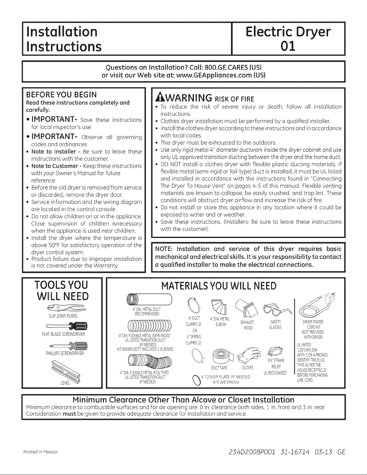
TOOLSYOU
MATERIALSYOUWILL NEED
WILL NEED
4"DIA.METALDUCT
SLIPJOINTPLIERS
FLATBLADESCREWDRIVER
PHILLIPSSCREWDRIVER
(RECOMMENDED}
4"DIA,FLEXIBLEMETAL(SEMPRIGID)
ULLISTEDTRANSITIONDUCT
KITWXOBX!O077(INCLUDES2ELBOWS}
4"DIA.FLEXIBLEMETAL(FOILTYPE)
(IFNEEDED)
ULLISTEDTRANSITIONDUCT
(IFNEEDED,)
#'DUCT
CLAMPS(2) EXHAUST
OR
#'SPRING
CLAMPS(2)
Minimum Clearance Other Than Alcove or Closet Installation
Minimum clearance to combustible surfaces and for air opening are: 0 in. clearance both sides, 1 in. front and 3 in.rear.
Consideration must be given to provide adequate clearance for installation and service.
Printedin Mexico 234D2008PO01 31-16714 03-13 GE
%
4"DIA,METAL
ELBOW
DUCTTAPE GLOVES
HOOD
%
SAFETY
GLASSES
3/4"STRAIN
RELIEF
ULRECOGNIZED
DRYERPOWER
CORDKIT
(NOTPROVIDED
WITHDRYER)
ULRATED
!20/240V,30A
WITH3OR4PRONGS,
IDENTIFYTHEPLUG
TYPEASPERTHE
HOUSERECEPTACLE
BEFOREPURCHASING
LINECORD,
Page 2
Installation Instructions
[iIPREPARING FOR INSTALLATION OF
NEW DRYER
TIP:Install your dryer before installing your washer.
This will allow better access when installing dryer exhaust.
REMOVING LINT FROM WALL EXHAUST
OPENING
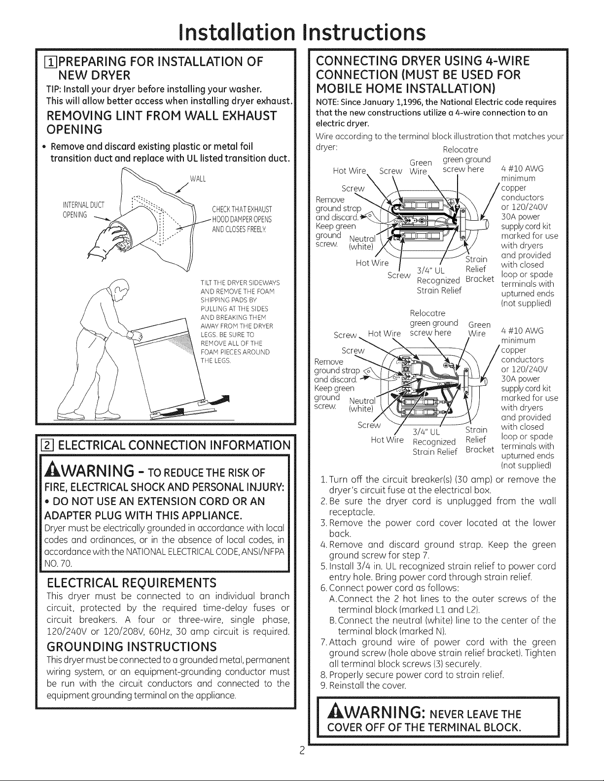
• Remove and discard existing plastic or metal foil
transition duct and replace with UL listed transition duct.
WALL
INTERNALDUCT
OPENING OPENS
CHECKTHATEXHAUST
ANDCLOSESFREEL_
TILTTHE DRYERSIDEWAYS
AND REMOVETHE FOAM
SHIPPING PADS BY
PULLING ATTHE SIDES
AND BREAKING THEM
AWAY FROMTHE DRYER
LEGS.BE SURETO
REMOVEALLOFTHE
FOAM PIECESAROUND
THE LEGS.
E_]ELECTRICAL CONNECTION INFORMATION
WARNING - TO REDUCE THE RISKOF
FIRE,ELECTRICALSHOCK AND PERSONAL INJURY:
, DO NOT USE AN EXTENSION CORD OR AN
ADAPTER PLUG WITH THIS APPLIANCE.
Dryer must be electrically grounded in accordance with local
codes and ordinances, or in the absence of local codes, in
accordance with the NATIONALELECTRICALCODE,ANSI/NFPA
NO.70.
ELECTRICAL REQUIREMENTS
This dryer must be connected to an individual branch
circuit, protected by the required time-delay fuses or
circuit breakers. A four or three-wire, single phase,
120/240V or 120/208V, 60Hz, 30 amp circuit is required.
GROUNDING INSTRUCTIONS
Thisdryer must be connected to a grounded metal, permanent
wiring system, or an equipment-grounding conductor must
be run with the circuit conductors and connected to the
equipment grounding terminal on the appliance.
CONNECTING DRYER USING 4-WIRE
CONNECTION (MUST BE USED FOR
MOBILE HONE INSTALLATION)
NOTE: Since January 1,1996, the National Electric code requires
that the new constructions utilize a 4-wire connection to an
electric dryer.
Wire according to the terminal block illustration that matches your
dryer: Relocatre
Hot Wire Screw Wire screw here
Screw [
Remove
ground strap
and
Keepgreen
ground
screw. (white)
Hot Wire Strain
Screw_ Hot W(e
Green greenground
3/4" UL Relief
Screw
Recognized Bracket
Strain Relief
Relocatre
green ground Green
screw here Wire 4 #10 AWG
Scre_ _X_/\ / copperminimum
groundstrop _ _ or !20/240V
anddiscord._ 30Apower
Keepgreen _ supplycordkit
ground Neutral / "j_ markedfor use
Remove _/_"_,__)conductors/_\
screw. (white) \/_ ! with dryers
Screw "- 3/4" UL Strain with closed
HotWire Recognized Relief loop orspade
StrainRelief Bracket terminalswith
1.Turn off the circuit breaker(s) (30 amp) or remove the
dryer's circuit fuse at the electrical box.
2.Be sure the dryer cord is unplugged from the wall
receptacle.
3.Remove the power cord cover located at the lower
back.
4. Remove and discard ground strap. Keep the green
ground screw for step 7.
5.Install 3/4 in. UL recognized strain relief to power cord
entry hole. Bring power cord through strain relief.
6.Connect power cord as follows:
A.Connect the 2 hot lines to the outer screws of the
terminal block (marked L1 and L2).
B.Connect the neutral (white) line to the center of the
terminal block (marked N).
7.Attach ground wire of power cord with the green
ground screw (hole above strain relief bracket). Tighten
all terminal block screws (3)securely.
8. Properly secure power cord to strain relief.
9. Reinstall the cover.
4 #10 AWG
minimum
conductors
or !20/240V
30A power
supplycord kit
marked for use
with dryers
and provided
with closed
loop or spade
terminals with
upturned ends
(not supplied)
and provided
upturnedends
(notsupplied)
[ kWARNING: NEVER LEAVE THE J
COVER OFF OF THE TERMINAL BLOCK.
Page 3
Installation Instructions
CONNECTING DRYER USING 3-WIRE
CONNECTION
tf required, by local code, install external ground (not provided)
to grounded metal, cold water pipe, or other established ground
determined by a qualified electrician.
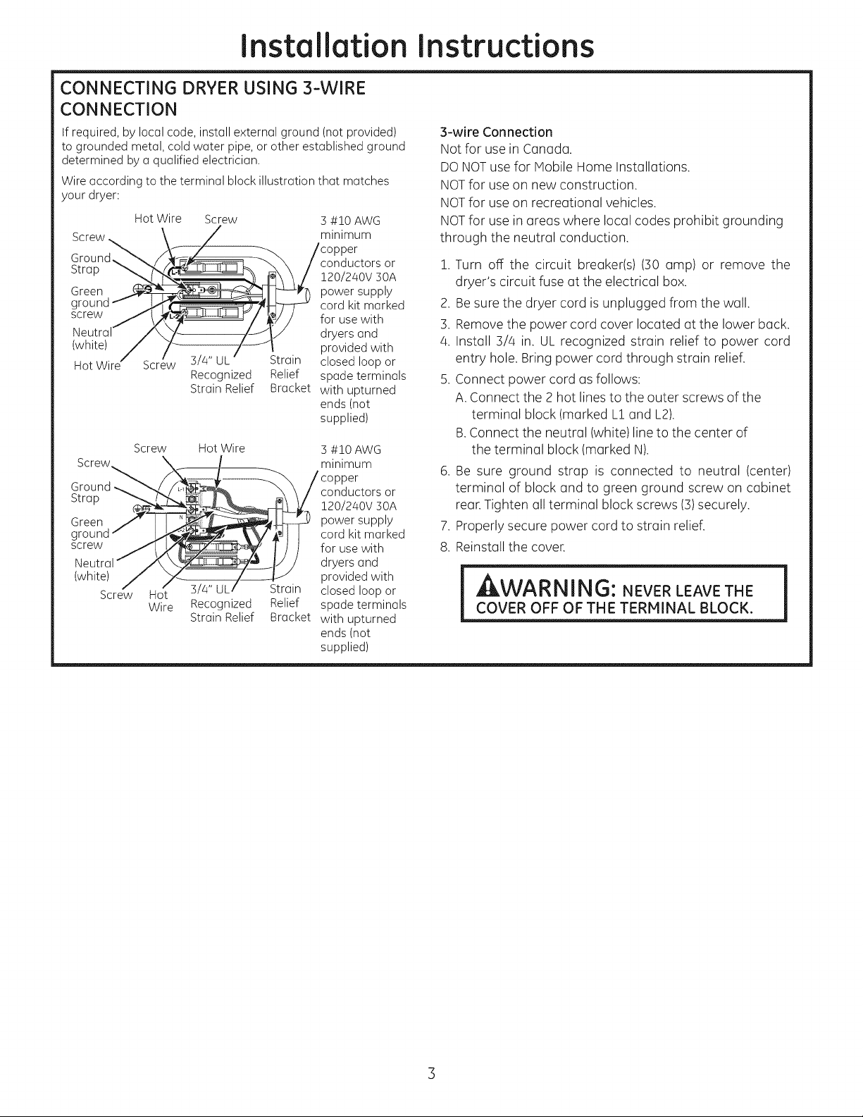
Wire according to the terminal block illustration that matches
your dryer:
Hot Wire Screw
Screw
Ground,
Strap
Green
g
screw
(white)
Screw
Screw
Screw_ \
rou L. *
Strap
Green _r_
gr°e"nd"
Neutral'_ x_,_
(white)
Screw Hot
Wire
3/4" UL Strain
Recognized Relief
Strain Relief Bracket
Hot Wire 3 #10 AWG
_/. minimum
__.,AJ_/ Y 120/240V 30A
_- \V_'Jl I cordkitmarked
___ I ) / for usewith
_,_ IJ/ dryersand
__ 1lt_L__£t rnin providedwith
3/4" UL Strain closedloopor
Recognized Relief spadeterminals
StrainRelief Bracket with upturned
3 #10 AWG
minimum
)er
conductors or
120/240V 30A
power supply
cord kit marked
for use with
dryers and
provided with
closed loop or
spade terminals
with upturned
ends (not
supplied)
/co or
y con ctor or
powersupply
ends(not
supplied)
S-wire Connection
Not for use in Canada.
DO NOTuse for Mobile Home Installations.
NOTfor useon new construction.
NOTfor useon recreational vehicles.
NOTfor use in areas where local codes prohibit grounding
through the neutral conduction.
1. Turn off the circuit breaker(s) (30 amp) or remove the
dryer's circuit fuse at the electrical box.
2. Be sure the dryer cord is unplugged from the wall.
3. Remove the power cord cover located at the lower back.
4. Install S/4 in. UL recognized strain relief to power cord
entry hole. Bring power cord through strain relief.
5. Connect power cord as follows:
A.Connect the 2 hot lines to the outer screws of the
terminal block (marked L1 and L2).
B.Connect the neutral (white)line to the center of
the terminal block (marked N).
6. Be sure ground strap is connected to neutral (center)
terminal of block and to green ground screw on cabinet
rear.Tighten all terminal block screws (S)securely.
7. Properly secure power cord to strain relief.
8. Reinstall the cover.
l covEROFFOFr.ErERni.ALBLOCK.1
Page 4
Installation Instructions
[-3]EXHAUST INFORMATION
WARNÁNG -IN CANADAANDINTHE
UNITED STATES, THE REQUIRED EXHAUST DUCT
DIAMETER IS 4 in I102mm). DO NOT USE DUCT
LONGER THAN SPECIFIED IN THE EXHAUST
LENGTH TABLE.
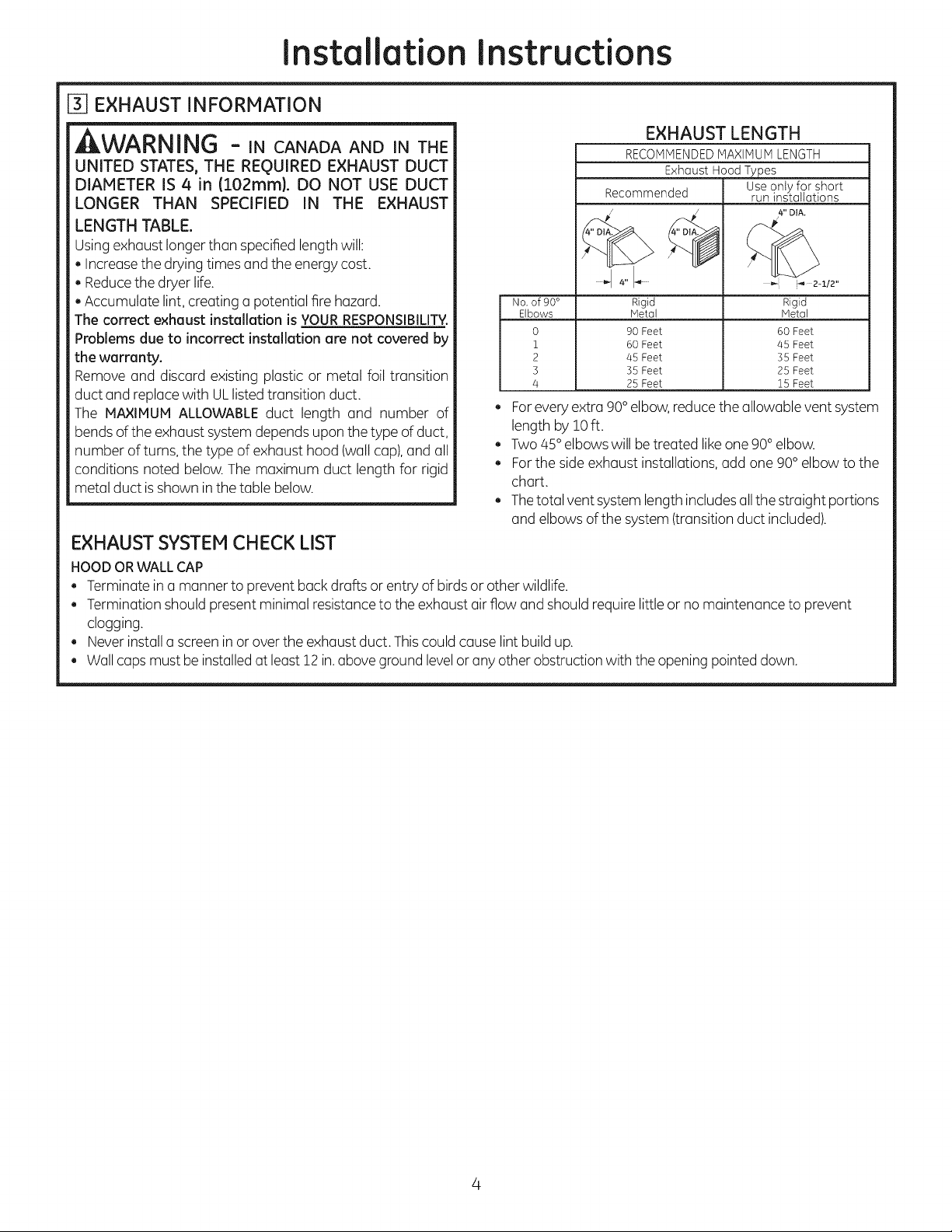
EXHAUST LENGTH
RECOMMENDED lvtAXIiVlUivtLENGTH
Exhaust Hood Types
Recommended
Use only for short
run installations
4" DIA.
Usingexhaust longer than specified length will:
. Increasethe drying times and the energy cost.
. Reducethe dryer life.
. Accumulate lint, creating a potential fire hazard.
The correct exhaust installation is YOURRESPONSIBILITY.
Problems due to incorrect installation are not covered by
the warranty.
Remove and discard existing plastic or metal foil transition
No, of 90 °
Elbows
0
1
2
3
4
Rigid
Metal
90 Feet
60 Feet
45 Feet
35 Feet
25 Feet
_'- i-_ 2-:1./2"
Rigid
Metal
60 Feet
/45 Feet
35 Feet
25 Feet
15 Feet
duct and replacewith ULlistedtransition duct.
The MAXIMUM ALLOWABLE duct length and number of
bendsof the exhaust system depends upon the type of duct,
number of turns, the type of exhaust hood (wall cap),and all
conditions noted below. The maximum duct length for rigid
metal duct isshown inthe table below.
. Forevery extra 90°elbow,reduce the allowable ventsystem
length by !0 ft.
. Two/45° elbows will be treated like one 90°elbow.
. Forthe side exhaust installations, add one 90° elbow to the
chart.
. Thetotal vent systemlength includesallthe straight portions
and elbows ofthe system (transition duct included).
EXHAUST SYSTEM CHECK LIST
HOODORWALLCAP
. Terminatein a manner to prevent back drafts or entry of birds or other wildlife.
. Termination should present minimal resistanceto the exhaust air flow and should require little or no maintenance to prevent
clogging.
. Never installa screenin or over the exhaust duct. Thiscould cause lint build up.
. Wallcaps must beinstalledat least !2 in.aboveground levelor any other obstruction with the opening pointed down.
Page 5
Installation
nstructions
EXHAUST SYSTEM CHECK LiST(cont.)
SEPARATIONOF TURNS
For best performance, separate all turns by at least 4 ft. of
straight duct, including distance between last turn and exhaust
hood.
TURNSOTHERTHAN90°
, One turn of 450or lessmay be ignored.
, Two a50turns should betreated as one 90°turn.
, Eachturn over450should be treated usone 900turn.
SEALINGOFJOINTS
, Alljoints should be tight to avoid leaks.Themale end of each
section of duct must point away from the dryer.
, The duct shall not be assembled with screws or other
fastening means that extend into the duct and catch lint.
, Ductjoints can be made air and moisture-tight by wrapping
the overlappedjoints with duct tape.
, Horizontal runs should slope down toward the outdoors 1/4
inchper foot.
INSULATION
Duct work that runs through an unheated area or is near air
conditioning should be insulated to reduce condensation and
lint build-up.
[-4-]EXHAUST CONNECTION
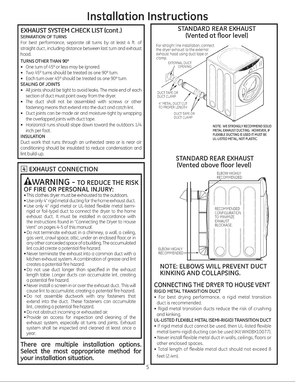
STANDARD REAR EXHAUST
(Vented at floorlevel)
For straight line installation, connect
the dryer exhaust to the external
exhaust hood using duct tape or
clamp.
EXTERNALDUCT
DUCT TAPEOR
DUCT CLAMP
4" METALDUCT CUT
TO PROPERLENGTH
DUCTTAPE OR
DUCTCLAMP
NOTE: WE STRONGLY RECOMMEND SOLID
METAL EXHAUST DUCTING. HOWEVER, IF
FLEXIBLEDUCTING ISUSED ITMUST BE
UL-LISTEDMETAL,NOT PLASTIC.
STANDARD REAR EXHAUST
(Vented above floorlevel)
ELBOWHIGHLY
WARNING -TOREDUCETHERiSK
OF FiRE OR PERSONAL iNJURY:
,This clothes dryer must be exhaustedto the outdoors.
, Useonly #' rigid metal ducting for the home exhaustduct.
, Use only a" rigid metal or UL-listed flexible metal (semi-
rigid or foil-type) duct to connect the dryer to the home
exhaust duct. It must be installed in accordance with
the instructions found in "Connecting the Dryerto House
Vent"on pagesa-5 of this manual.
, Do not terminate exhaust in a chimney, a wall, a ceiling,
gas vent, crawl space,attic, under an enclosedfloor, or in
anyother concealed spaceofa building.Theaccumulated
lint could create a potential fire hazard.
, Never terminate the exhaust into a common duct with a
kitchen exhaust system.A combination of grease and lint
creates a potential fire hazard.
, Do not use duct longer than specified in the exhaust
length table. Longer ducts can accumulate lint, creating
a potential fire hazard.
, Never installa screen inor over the exhaust duct. Thiswill
cause lint to accumulate, creating a potential fire hazard.
,Do not assemble ductwork with any fasteners that
extend into the duct. These fasteners can accumulate
lint, creating a potential fire hazard.
, Do not obstruct incoming or exhausted air.
, Provide an access for inspection and cleaning of the
exhaust system, especially at turns and joints. Exhaust
system shall be inspected and cleaned at least once a
year.
There are multiple installation options.
Select the most appropriate method for
your installation situation.
RE_I If!
TOMINIMIZE _!1
EXHAUST: I,_,!i
BLOCKAGE. I I_l
i i I I i
ELBOWHIGHLY
RECOMMENDED-
NOTE: ELBOWS WILL PREVENT DUCT
KINKING AND COLLAPSING.
CONNECTING THE DRYERTO HOUSE VENT
RIGID METALTRANSITION DUCT
, For best drying performance, a rigid metal transition
duct isrecommended.
, Rigid metal transition ducts reduce the risk of crushing
and kinking.
UL-LISTEDFLEXIBLEMETAL (SEMI-RIGID}TRANSITIONDUCT
, If rigid metal duct cannot be used, then UL-listed flexible
metal (semi-rigid)ducting can beused (Kit WXO8X10077).
, Never install flexible metal duct in walls, ceilings, floors or
other enclosed spaces.
, Total length of flexible metal duct should not exceed 8
feet (2.4m).
Page 6

Installation Instructions
, For many applications, installing elbows at both the dryer
and the wall is highly recommended (see illustrations
below). Elbows allow the dryer to sit close to the wall
without kinking and or crushing the transition duct,
maximizing drying performance.
, Avoid resting the duct on sharp objects.
UL-LISTEDFLEXIBLEMETAL(FOIL-TYPE}TRANSITIONDUCT
, In special installations, it may be necessary to connect
the dryer to the house vent using a flexible metal (foil-
type) duct. A UL-listed flexible metal (foil-type) duct may
be used ONLYin installations where rigid metal or flexible
metal (semi-rigid) ducting cannot be used AND where a 4"
diameter can be maintained throughout the entire length
of the transition duct.
, In Canada and the United States, only the flexible metal
(foil-type) ducts that comply with the "Outline for Clothes
Dryer Transition Duct Subject 2158A" shall be used.
, Never install flexible metal duct in walls, ceilings, floors or
other enclosed spaces.
, Total length of flexible metal duct should not exceed 8 feet
(2.4m).
, Avoid resting the duct on sharp objects.
For best drying performance
1.Slide one end of the duct over the clothes dryer outlet
pipe.
2.Secure the duct with a clamp.
3.With the dryer in its permanent position, extend the duct
to its full length. Allow 2" of duct to overlap the exhaust
pipe. Cut off and remove excess duct. Keep the duct us
straight as possible for maximum airflow.
4.Secure the duct to the exhaust pipe with the other clamp.
LEVELING AND STABILIZING YOUR
DRYER
Stand the dryer upright near the final location and adjust
the 4 leveling legs, at the corners, to ensure that the dryer
islevel from side to side and front to rear.
LEVEL LEVEL
FRONTTO BACK SIDE TO SIDE
ELBOWHIGHLY
RECOk_,MENDED
/
EXHAUST
LENGTH
(
4 LEVELING
LEGS
ALCOVE OR CLOSET INSTALLATION
, If your dryer is approved for installation in an alcove or
closet, it will be stated on a label on the dryer back.
,The dryer MUST be vented to the outdoors. See the
EXHAUSTINFORMATIONsections 3 & 4.
, Minimum clearance between dryer cabinet and adjacent
walls or other surfaces is:
0 in. either side
3 in.front
3 in. rear
, Minimum vertical space from floor to overhead cabinets,
ceiling, etc. is52 in.
.Closet doors must be Iouvered or otherwise ventilated
and must contain a minimum of 60 sq. in. of open area
equally distributed. If the closet contains both a washer
and a dryer, doors must contain a minimum of 120 sq. in.
of open area equally distributed.
NOTE:WHENTHEEXHAUSTDUCTISLOCATEDATTHEREAROF
THEDRYER,MINIMUMCLEARANCEFROMTHEWALLIS5.5in.
Page 7

Installation instructions
_7 BATHROOM OR BEDROOM INSTALLATION
.ThedryerMUST be ventedtotheoutdoors.See EXHAUST
INFORMATION section3 & 4.
. The installation must conform with local codes or, in the
absence of local codes, with the NATIONALELECTRICAL
CODE,ANSI/NFPANO.70.
[_MOBILE OR MANUFACTURED HOME
INSTALLATION
. Installation must conform to the MANUFACTUREDHOME
CONSTRUCTION& SAFETYSTANDARD,TITLE 24, PART
32-80 or, when such standard is not applicable, with
AMERICAN NATIONAL STANDARD FOR MOBILE HOME,
ANSI/NFPANO.50lB.
.The dryer MUST be vented to the outdoors with the
termination securely fastened to the mobile home
structure. (SeeEXHAUSTINFORMATIONsection 3 & 4).
.The vent MUSTNOT be terminated beneath a mobile or
manufactured home.
.The vent duct material MUSTBEMETAL.
. Do not use sheet metal screws or other fastening devices
which extend into the interior of the exhaust vent.
. Seesection 2for electrical connection information.
FIXINGHOLE
B A
_" 9"
Cut the duct as shown and keep portion A.
TAB LOCATION
BENDTAB
UP45o
Through the rear opening, locate the tab in the middle of
the appliance base. Lift the tab to about 450using a flat
blade screwdriver.
[97GARAGE INSTALLATION (IF ALLOWED
BY LOCAL CODES)
Dryers installed in garages must be elevated !8 inches
(46cm) above the floor.
[]DRYER EXHAUST TO RIGHT, LEFT OR
BOTTOM CABINET
, WARNING - BEFOREPERFORMING
THIS EXHAUST INSTALLATION, BE SURE
TO DISCONNECT THE DRYER FROM ITS
ELECTRICAL SUPPLY. PROTECT YOUR
HANDS AND ARMS FROM SHARP EDGES
WHEN WORKING INSIDE THE CABINET.
BE SURE TO WEAR GLOVES.
i
REPIOVE
SCREW
ANDSAVE
ADDING NEW DUCT
FIXING
HOLE
RIGHTOR
LEFTSIDE
EXHAUST
Reconnectthe cut portion (A)of the duct to the blower
housing, iVtakesure that the shortened duct isaligned with
the tab in the base.Usethe screw saved previouslg to secure
the duct in place throuqh the tab on the appliance base.
REMOVEDESIRED
KNOCKOUT(0NEONLY).
Detach and remove the bottom, right or left side knockout
as desired. Remove the screw inside the dryer exhaust duct
and save. Pull the duct out of the dryer.
Page 8

Installation instructions
ADDING ELBOW AND DUCT FOR
EXHAUST TO LEFT OR RIGHT SIDE OF
CABINET
. Preassemble 4" elbow with 4" duct. Wrap duct tape
around joint.
* Insert duct assembly, elbow first, through the side
opening and connect the elbow to the dryer internal
duct.
ACAUTION: Be sure nottopullor damage the
electrical wires inside the dryer when inserting the duct.
!,_;_.......
EXHAUSTCAN
BEADDEDTO
LEFTORRIGHTSIDE
"_j!i_ .......s--_j
DUCT
TAPE
ADDING COVER PLATE TO REAR OF
CABINET (SIDESAND BOTTOM EXHAUST)
PLATE
{KITWEIM454)
Connect standard metal elbows and ducts to complete
the exhaust system. Cover back opening with a plate (Kit
WE1M45/4)available from your local service provider. Place
dryer in final location.
_WARNING-NEVER LEAVE THE
BACK OPENING WITHOUT THE PLATE
(KitWEIM454).
.Apply duct tape as shown on thejoint between the
dryer internal duct and the elbow.
DUCT CAUTION:
Internal duct joints must be
secured with tape, otherwise
they may separate and cause a
[_ safety hazard.
ADDING ELBOW FOR EXHAUST
THROUGH BOTTOM OF CABINET
. Insert the elbow through the rear opening and connect
it to the dryer internal duct.
. Apply duct tape on the joint between the dryer internal
duct and elbow, as shown above.
REGISTER YOUR NEW APPLIANCE TO RECEIVE ANY
IMPORTANT PRODUCT NOTIFICATIONS.
Please go to www.GEAppliances.com or mail in
your product registration card.
For questions on installation, call: 800.626.2000 (US)or
800-561-3344 (Canada).
CAUTION:
internal duct joints must be secured with tape,
otherwise they may separate and cause a
safety hazard.
Page 9

Instrucciones
Secadora El@ctrica
de instalaci6n
j 2.Preguntas sobre la Llame al: 1-800-GECARES (EE.UU.) |
instalaci6n?
01
o visite nuestro sitio Web en: www.GEAppliances.com (EE.UU.)
ANTES DE COMENZAR
Lea estos instrucciones por completo y con
detenimiento.
. IMPORTANTE - Guerdeestesinstrucciones
peru el usode inspectores locales.
. IMPORTANTE - siga todos los c6digos y
ordenanzasvigentes.
. Noto ol instolodor - AsegOresede dejar estas
instruccionescon el consumidor.
. Note al consumidor ivlantenga estas
instruccionescon el Manual del Propietariopara
referenciafutura.
. Antesde que le secedoreantigua sea retirede del
serviciooeliminodo,qufteleIopuerto.
. Lainformaci6n sobrereparacionesyeldiagrama
del cableado se encuentran en la consola de
control.
, No permite que ni_os se suben o se meton
dentro del apereto. Serequiere una supervisi6n
estricta cuando el aparato es utilizado cerca de
niflos.
* Instale la secadora en lugares donde la
ADVERTENCIA RIESGO DE INCENDIO
. Peru reducir el riesgo de una lesi6n grove o de muerte, cumpla con todas
los instrucciones de instelaci6n.
. Lo instelaci6n de la secadore debe efectuarle un instaledor celificado.
Instale la secadora de ropa de acuerdo con estas instrucciones y en
cumplimiento de los c6digos locales.
. Esta secadora debe tener una selida al exterior.
. Utilice s61oun conducto rfgido de metal de un di6metro de 4" dentro del
gebinete de le secadora y use s61oun conducto de transici6n aprobado
por ULentre la secadora y el conducto dom6stico.
. NO instale una secedore de rope con conductos de pldstico flexibles. Si
se instale un conducto fexible de metal (semi r[gido o de tipo papel de
aluminio), debe estar aprobado por ULe instalarse de acuerdo con los
instrucciones de "C6mo conectar la secadora a laventilaci6n dom6sticd'
de los p6ginas 4-5 de este manual. Los materiales de ventilaci6n
flexibles a menudo se desploman, se eplaston y atrapen pelusas. Estas
condiciones obstruyen lacorriente de aire de la secadora eincrementan
el riesgo de incendio.
. No instale o almacene este aparato en un lugar donde se yea expuesto
al ague y/o a los inclemencias del tiempo.
* Guarde estas instrucciones. (Instaladores: AsegOrese de dejar estas
instrucciones al consumidor).
temperatura sea mayor a 50°F para un
funcionamiento sotisfactorio del sistema de
control de la secadora,
* La garant[a no cubre los fallas del producto
debido a una instalaci6n incorrecta.
NOTA: La instalaci6n y reparaci6n de esta secadora requieren
capacidades mec_nicas y el_ctricas b6sicas. Es su responsabilidad
contactar a un Jnstalador calJficado para realJzar las cone×Jones
el_ctricaso
HERRAMIENTAS
NECESARIAS
ALICATESDEJUNTADESLIZANTE
DESTORNILLADORPLANO
DESTORNILLADORDEESTRELLA
CONDUCTODEMETALDE4"DEDI#,
(RECOMENDADO}
CONDUCTODETRANSICIONDEMET,AL
FLEXIBLE(SEMIRIGIDO)DE4"DEDIA.
APROBADOPORUL(SIFUERANECESARIO}
KITWXOBXl_OO77(INCLUVE2CODOS)
CONDUCTODETRANSICIONDEMETAL
FLEXIBLEFIPOPAPELDEALUMINIO)DE4"DEDI#,,
APROBADOPORUL(SIFUERANECESARIO)
MATERIALES
)
ABRAZADERAS
DECONDUCTODE4"(2)
O
ABRAZADERAS
DERESORTEDE4"(2)
4 "PLACA DE CUBIERTA
NECESARIOS
CODODEMETAL
DE4"DEDIA, CAMPANA GAFAS
CINTAADHESIVA
DESALIDADESEGURIDAD
GUANTES DEs#,RECONOCIDO
ALIVIODETENSION
(5
PORUL
KITDECABLE
DEENERGiA
DELASECADORA
(NOPROVBTACON
LASECADORA)
CAPACIDAD UL DE
220/240_30A
CON ] 0 4 PUNTAS
ANTES DE COIvlPRAR EL
CORDON IDENTIFIQUE
EL TIPO DE ENCHUFE DE
ACUERDO CON EL
RECEPTACULO
DE LA CASA
Espacio minimo diferente a instalaci6n en nichos o closets
Losespacioslibresminimosrespectodesuperficiescombustiblesy deaberturasde aireson:Espaciode0 pulg.aamboslados,! pulg.enel
frentey 3 pulg.enla partetrasera.Debetenerseencuentaun espaciolibreadecuadopara unfuncionamientoy reparaci6ncorrectos.
Impresoen M4xico 234D2008PO01 3J-J6714 03-J3 GE
Page 10

Instrucciones
de instoloci6n
[1]PREPARACI6N PARA LA INSTALACI6N
DE UNA SECADORA NUEVA
CONSEJO: Instale su secadora antes de instalar la
lavadora. Esto permitir6 un mejor acceso cuando
instale la salida de la secadora.
COMO QUITAR PELUSA DE LA ABERTURA
DE LA SALIDA DE LA PARED
. Quite y descarte el conducto de transici6n existente de
pl6stico o de papel de oluminio y coloque un conducto
de transici6n aprobado por UL.
VERLFLQUE QUE
EL REGULADOR
DE TIRO DE LA CAP1PANA
DE SALIDA SE ABRA
Y CIERRE UBREMENTE
INCLINE LA SECADORA
DE COSTADO Y QUITE
LAS ALMOHADILLAS
DE ESPUMA PARA ENV[O
TOMANDOLAS DE LOS
COSTADOS Y
ARRANCANDOLAS DE LAS
PATAS DE LA SECADORA.
ASEGORESE DE QUITAR
TODAS LAS PIEZAS
DE ESPUMA UBICADAS
ALREDEDOR DE LAS PATAS.
[_]INFORMACI6N SOBRE CONE×IONES
ELECTRICAS
ADVERTENCIA - PARARE DUCIR EL
RIESGO DE INCENDIO, DESCARGA ELECTRICA
Y LESIONES PERSONALES:
, NO UTILICEUN CABLE DE EXTENSION O UN
ENCHUFE ADAPTADOR CON ESTE APARATO.
La secadora debe contar con una conexi6n el6ctrica a
tierra en cumplimiento con los c6digos y ordenanzas
locales, o si 6stos no existieran, de acuerdo con el CODIGO
ELECTRICONACIONAL,ANSI/NFPAN°. 70.
REQUISITOS ELI_CTRICOS
Esta secadora debe conectarse a un circuito derivado
individual, con la protecci6n de los fusibles de tiempo
retardado o interruptores de circuito requeridos. Serequiere
un circuito de tres o cuatro cables, fase 0nica, 120/240V 6
120/208V, 60Hz y :30amperios.
INSTRUCCIONES DE CONE×I6N A TIERRA
Esta secadora debe conectarse a un sistema de cableado
permanente con conexi6n a tierra o debe utilizarse un
conductor de conexi6n a tierra del equipamiento con
los conductores de circuito y conectarse a la terminal de
conexi6n a tierra del aparato.
COMO CONE CTAR LA SECADORA USANDO
UNA CONE×ION DE4 CABLES(DEBEUTILIZARSE
EN INSTALAClONES DE CASAS H6VILES)
NOTA: Desde el I de enero de 1996, el C6digo ElSctrico Nacional
exige que las nuevas construcciones utilicen una conexi6n de 4
cables a una secadora el_ctrica.
Canecte de acuerda can la ilustraci6n del blaque terminal que
correspondea su secadora: Vuelvaa 4 conductores
Cable Cable tornillo verde AWG minima
vivo Tornillo verde de conexi6n o kit decable
Tornillo
Quite la cinta._.
de conexi6n
a tierra y
desc@tela. Neutral
Conserve (blanco)
el tornillo
verde de
conexi6n vivo
a tierra.
Tornillo
Tornillo reconocidoporUL
Alivio de de alivio
tensi6n de 3/4" de tensi6n
Cable
Tornillo
Quite la cinta
de conexi6n
a tierra y
desc@tela.
Conserve (blanco)
el tornillo
verde de
conexi6n
a tierra.
tensi6n de 3/4" de alivio
vivo reconocidoporUL detensi6n (noprovistos).
1.Desactive el interruptor de circuitos (:30amperios) o quite
el fusible del circuito de la secadora de la caja el@ctrica.
2.Verifique que elcable de la secadora est6 desenchufado
del tomacorriente.
3. Quite la tapa del cable de energ[a ubicada en la parte
trasera inferior.
4.Quite y descarte la cinta de conexi6n a tierra. Conserve
el tornillo verde de conexi6n a tierra para el paso 7.
5. Instale un alivio de tensi6n de sA pulgadas reconocido
pot UL en el orificio de entrada del cable de energfa.
Paseel cable de energfa a trav6s del alivio de tensi6n.
6.Conecte el cable de energ[a de la siguiente manera:
A. Conecte los dos cables vivos a los tornillos externos
del bloque terminal (marcado L1y L2).
B.Conecte el cable neutral (blanco) al centro del bloque
terminal (marcado N).
7. Conecte el cable a tierra del cable de energfa con el
tornillo verde de conexi6n a tierra (orificio sobre el
soporte de alivio de tensi6n). Ajuste por firmemente
todos los tornillos (3)del bloque terminal.
8.Ajuste bien el cable de energ[a al alivio de tensi6n.
9.Vuelva a instalar latapa.
colocar el de cobre #10
a tierra aqui. de suministro
oporte
Vuelva a
colocar el
tornillo verde Cable
de conexi6n verde
a tierra
Soporte
30A
marcado para
su uso con
secadoras y
provisto con
terminales de
bucle cerrado
o hembra
con extremos
hacia arriba
(no provistos).
4 conductores
de cobre #10
AWG minima
o kit de cable
de suministro
de energ[a de
!20/240V 30A
marcado para
su uso con
secadoras y
provisto con
terminales de
bucle cerrado
o hembra
con extremos
hacia arriba
A ADVERTENCIA: NUNCA OLVIDE DE
VOLVERA COLOCAR LATAPA DELBLOQUE TERHINAL.
Page 11

Instrucciones de instalaci6n
C6MO CONECTAR LA SECADORA
UTILIZANDO UNA CONE×I6N DE 3 CABLES
SiasiIorequirieranlosc6digoslocales,instaleuna conexi6natierra
externa (noprovista)ametal con conexi6natierra, tuberiasde
agua fria con conexi6natierra u otra conexi6na tierra establecida
por unelectricistacalificado.
Conectedeacuerdoconla ilustraci6ndel bloqueterminal que
correspondea su secadora:
Cintade.
atierra
Tornillo
verde de
conexi6n
atierra
Neutral
(blanco)
Cable
vivo
Cinta¢te_
conexlon
atierra
Tornillo
verde de
conexi6n
atierra
(blanco)
Tornillo
Cable vivo Tornillo
Iio Alivio Soporte
tensi6n de
de 3/4" alivio
reconocido de
por UL tensi6n
Tornillo
Cable
VlVO
Cablevivo
Alivio de'
tensi6n
de 3/4"
reconocido
por UL
oporte
de
alivio
de
tensi6n
3 conductores
de cobre #!0
minimo
o kit de cable
de suministro
de energ[a de
!20/240V 30A
marcado para su
uso con secadoras
y provisto con
terminales de
bucle cerrado
o hembra
con extremos
hacia arriba (no
provistos).
3 conductores
de cobre #!0
minimo
o kit de cable
de suministro
de energ[a de
!20/240V 30A
marcado para su
uso con secadoras
y provisto con
terminales de
bucle cerrado
o hembra
con extremos
hacia arriba (no
provistos).
Conexi6n de 3 cables
NO usar en Canad6.
NO usar en instalaciones en casas m6viles.
NO usar en casas nuevas.
NO usar en veh[culos recreativos.
NO usar en 6reas donde los c6digos locales prohiben la
connexi6n el6ctrica a tierra por el medio del cable neutral.
!. Desactive el interruptor de circuitos (30 amperios) o quite
el fusible del circuito de la secadora de la caja el6ctrica.
2. Verifique que el cable de la secadora est6 desenchufado
del tomacorriente.
3. Quite la tapa del cable de energ[a ubicada en la parte
trasera inferior.
4. Instale un alivio de tensi6n de sA pulgadas reconocido
por ULen el orificio de entrada del cable de energ[a. Pase
el cable deenerg[a atrav6s del alivio de tensi6n.
5. Conecte el cable de energ[a de la siguiente manera:
A.Conecte losdos cables vivos a los tornillos externos del
bloque terminal (marcado L! y L2).
B.Conecte el cable neutral (blanco) al centro del bloque
terminal (marcado N).
6. Aseg0rese de que la cinta de conexi6n a tierra est6
conectada a la terminal neutral (central) del bloque y al
tornillo verde de conexi6n a tierra de la parte trasera del
gabinete. Ajuste por firmemente todos los tornillos (3)del
bloque terminal.
7. Ajuste bien el cable de energ[a al alivio de tensi6n.
8. Vuelva a instalar la tapa.
, ADVERTENCIA:NUNCA
OLVIDE DE VOLVER A COLOCAR LA
TAPA DEL BLOgUE TERMINAL.
Page 12

Instrucciones de instalaci6n
INFORMACI6NDESALIDA
ADVERTENCIA - EN CANADAY
LOS ESTADOS UNIDOS, EL DIAMETRO
DE CONDUCTO DE SALIDA REQUERIDO
ES DE 4 PULG. (I02 mm). NO UTILICE UN
CONDUCTO DE UNA LONGITUD MAYOR
A LA ESPECIFICADA EN LA TABLA DE
LONGITUD DE SALIDA.
AI utilizar una salida de mayor Iongitud a la especificada se:
• Incrementar6n lostiemposde secadoy el costo de energia.
, Reducir6 la vida 0til de lasecadora.
, Acumular6 pelusa, Io que podria generar un riesgo
potencial de incendio.
La correcta instalaci6n de salida es S_U
RESPONSABILIDAD.Los problemas generados por una
instalad6n incorrecta no se encuentran cubiertos por
la garantia.
Quite y descarte el conducto de transici6n existente de
pl6stico o de papel de aluminio y coloque un conducto de
transici6n aprobado por UL.
La Iongitud MAXIMA PERMITIDA del conducto y la
cantidad de codos del sistema de salida dependen
del tipo de conducto, la cantidad de curvas, la clase
de campana de salida (cubierta de pared) y todas las
condiciones indicadas a continuaci6n. La Iongitud
maxima del conducto para conductos r[gidos de metal
se indica en la siguiente tabla.
LONGITUDDESAUDA
LONGITUD MAXllVlA RECOMENDADA
Cant. de
codas de 90°
0
i
2
3
Tipos de campana de salida
Recomendado
Metal
Rigido
90 Pies
60 Pies
45 Pies
35 Pies
Utilizar s61o en instalaciones
de travecto corto
4" DIA.
....._ "_ 2-1/2"
Metal
Rigido
60 Pies
45 Pies
35 Pies
25 Pies
. Paracada codo adicional de 90°, reduzca en 10 pies la
Iongitud permisible del sistema de escape.
• Doscodosde4S°deber6nserconsideradoscomouncodode
90°'
Paraelescape lateral,agregue un codo de 90° a la tabla.
LaIongitud total del sistema de escape incluye todas las
porciones rectasy todos los codosdelsistema (incluyendo
el ducto de transici6n).
LISTADE CONTROL DEL SISTEMA DE SALIDA
CAMPANA O CUBIERTADEPARED
, Instale la salida de modo deevitar contracorrientes o el ingreso de pajaros u otros insectos o animales.
, La boca de salida debe presentar una resistencia minima al flujo de salida y debe requerir poco o ning0n mantenimiento
para evitar las obstrucciones.
Nunca instale un filtro dentro o sobre el conducto de salida. Esto podrfa provocar una acumulaci6n de pelusa.
Page 13

Instrucciones de instalaci6n
LISTA DE CONTROL DEL SISTEMA DE SALIDA
(cont .)
. Lascubiertas de pared deben instalarse por Io menos a 12"
sobre el nivel del suelo o cualquier otra obstrucci6n con la
abertura apuntando hacia abajo.
SEPARACIONDECURVAS
Para un mejor desempeBo, separe todas las curvas con por Io
menos 4 piesdeconducto recto,incluyendo la distancia entre la
01timacurva y la campana de salida.
GIROSOUENO SON DE90°
. Ungiro de450o menos puede ignorarse.
. Dosgiros de 450deben tratarse como un giro de 90°.
. Todoslosgirosde mas de/450debentratarse como un giro de
900
SELLADODEJUNTAS
. Todas las juntas deben estar bien selladas para evitar
p@didas. El extremo macho de cada secci6n de conducto
debe apuntar endirecci6n opuesta a la secadora.
. El conducto no deberc_ instalarse con tornillos u otros
medios de sujeci6n que se extiendan dentro del conducto y
enganchen pelusas.
. Lasjuntas de losconductos deben ser herm6ticas al aire y a
la humedad mediante la superposici6n de juntas con cinta
aislante.
. Lostramos horizontales deben tener una inclinaci6n hacia el
exterior de 1/4" por pie.
AISLACI6N
Losconductos instalados a trav6s de una @ea sin calefacci6n
o ubicados cerca de un acondicionador de aire deben aislarse
para reducir lacondensaci6n y laacumulaci6n de pelusas.
w
@ CONE×ION A LA SALIDA
ADVERTENCIA - PARAREDUCIR
EL RIESGO DE INCENDIO O DE
LESlONES PERSONALES:
. Estasecadora de ropa debe tenet una salida al exterior.
. Utilice s61oun conducto de metal r[gido de 4" para el
conducto de salidadom_stico.
. Use s61oun conducto de metal r[gido de 4" o de metal
flexible (semir[gidoo de tipo papel de aluminio) aprobado
por UL para conectar la secadora al conducto de
salida dom6stico. Debe instalarse de acuerdo con las
instrucciones incluidas en "C6mo conectar la secadora
a la ventilaci6n dom6stica" de las pdginas 4-5 de este
manual.
. No instale la boca de salida dentro de una chimenea,
pared, cielorraso,ventilaci6n de gas, espacio entre pisos,
@ico,bajo un piso con cerramiento o en cualquier otro
espacio oculto de un edificio. Laacumulaci6n de pelusas
podr[a provocar un riesgo potencial de incendio.
. Nunca instale la boca de salida dentro de un conducto
com0n con el sistema de salida de la cocina. La
combinaci6n de grasa y pelusas podria provocar un
riesgopotencial de incendio.
.No utilice un conducto de una Iongitud mayor a la
especificada en latabla de Iongitud de salida.
Losconductos m6s largosacumulan pelusa,Ioque genera un
riesgopotencial de incendio.
. Nunca instale un filtro dentro osobre elconducto desalida.
Esto provocarc_ la acumulaci6n de pelusas, Io que genera
un riesgo potencial de incendio.
.No arme la red de conductos con sujeciones que se
extiendan dentro del conducto. Estas sujeciones pueden
acumular pelusa, Io que genera un riesgo potencial de
incendio.
. No obstruya el aire que entra y sale.
. Incluya un acceso para inspecci6n y limpieza del sistema
de salida, especialmente en las curvas y juntas. Elsistema
de salida debe inspeccionarse y limpiarse por Io menos
una vez al ano.
Existen opciones m_ltiples de instalaci6n.
Seleccione el m6todo m6s apropiado para su
instalaci6n.
SALIDA TRASERA EST/_NDAR(Ventilaci6n
a nivel del suelo)
Para una instalad6n en linea recta, conecte
la salida de la secadora a la campana
de salida al exterior con cinta aisiante
o una abrazadera.
ABERTURADE
CONDUCTO EXTERIOR
CINTA AISLANTE
DE CONDUCTO
CONDUCTO DE METAL
DE 4" CORTADO
CON LA LONGITUD ADECUADA
CINTA AISLANTE O
ABRAZADERA DE CONDUCTO
NOTA: RECOMENDAMOS ENF/_TICAMENTEELUSO
DECONDUCTOS DE SALIDA DE METAL SOLIDO.
SIN EMBARGO, Sl SE USAN CONDUCTOS FLEXIBLES,
ESTOSDEBEN SERDE METAL APROBADOS POR UL,
NO DE PLASTICO.
SALI DA TRASERA EST/_NDAR
(Ventilaci6n sobre el nivel del suelo)
SERECOMIENDA
__ ELUSODECODOS
PARAMINIMIZAR i ; I IiI
LASLO%SATL_UC!'0N ES i i_ l!ii i
i I_
SERECOMIENDA
ELUSO DECODOS--
Page 14

Instrucciones de instalaci6n
NOTA: LOS CODOS EVITAN QUE LOS
CONDUCTOS SE DOBLEN O CAIGAN.
C6MOCON ECTARLA SECADORA A LA
VENTILACION DOMESTICA
CONDUCTO DETRANSlCI6N DEMETALRJGIDO
Para un mejor desempeno de secado, se recomJenda un
conducto de transici6n de metal rfgido.
Losconductos de transici6n de metal rfgidosreducenelriesgo
de aplastamientos y torceduras.
CONDUCTO DE TRANSICI6N DE METAL FLEXIBLE
(SEMI-RJGIDO)APROBADOPORUL
Sino puede utilizarse un conducto demetal r[gido,entonces
puede usarse un conducto de metal flexible (semi-r[gido)
aprobado pot UL(KitWX08X!0077).
,Nunca instale conductos de metal flexibles en paredes,
cielorrasos,pisosu otros espacioscerrados.
La Iongitud total del conducto de metal flexible no deberB
superar los8 pies (2.4m).
Para muchas aplicaciones, se recomienda enf@icamente
la instalaci6n de codos en la secadora yen la pared (ver
ilustraciones de abajo). Loscodos permiten que la secadora
seubique cerca de la pared sintorcer o aplastar el conducto
de transici6n, Io que potencia al mBximo el desempeflo de
secado.
Nocoloque el conducto sobreobjetos afllados.
CONDUCTODETRANSICIONDEMETALFLEXIBLE(SEMI-RIGIDO)
APROBADOPORUL
, En instalacionesespeciales,puede ser necesario conectar la
secadora a la ventilaci6n dom@sticautilizando un conducto
de metal fexible (tipopapel de aluminio). Puedeutilizarseun
conducto de metal flexible (tipo papel de aluminio) aprobado
por ULSOLOen instalaciones en las que no pueden usarse
conductos de metal rfgidos o flexibles (semi-rfgidos)Y en las
que puede mantenerseun didmetro de 4"a Iolargode todo el
conducto de transici6n.
EnCanadey losEstadosUnidos,solamente deberc_nutilizarse
los conductos de metal flexibles (tipo papel de aluminio) que
cumplan con el "Resumenpara conductos de transici6n para
secadorasde ropa,Tema 2!58A".
*Nunca instale conductos de metal flexibles en paredes,
cielorrasos, pisosu otros espacioscerrados.
La Iongitud total del conducto de metal flexible no deber6
superar los8 pies (2.4m).
Nocoloque el conducto sobre objetosafllados.
NO U] ILICE
UNA LONGITUD
DE SALIDA EXCESIVA
( (
Para un mejor desempeOo de secado:
!. Deslice un extremo del conducto sobre la tuber[a de salida
de la secadora de ropa.
2.FUeel conducto con una abrazadera.
3.Con la secadora en su posici6n permanente, extienda el
conducto en su Iongitud total. Deje que se superpongan
2" de conducto con la tuber[a de salida. Corte y quite el
tramo de conducto que sobre. Mantenga el conducto
Io mSs recto posible para Iograr una corriente de aire
m5xima.
4. FUe el conducto a la tuber[a de salida con la otra
abrazadera.
i
)
i-B]C6MO NIVELAR Y ESTABILIZAR SU
SECADORA
CO
RECOMIENDA
ENFAT]CAMENTE
NIVELAR N]VELAR
FRENTE A PARTE TRASERA LADO A LADO
4 PATAS
DE NIVELACION
Coloque la secadora
en posici6n vertical
cerca de la ubicaci6n
deflnitiva y ajuste
las cuatro patas
de nivelaci6n, en
los extremos, para
garantizar que la
secadora se encuentre
nivelada de lado a lado
y del frente a la parte
trasera.
Page 15

Instrucciones
de instalaci6n
r6] INSTALACION EN NICHO O EN CLOSET
.Su secadora puede instalarse en un nicho o closet,
coma se indica en la etiqueta de la parte trasera del
aparato.
. Esta secadora DEBE tenet una ventilaci6n al exterior.
Ver la INFORMACION SOBRE SALIDA secciones 3 y 4.
. Elespacio libre minima entre el gabinete de la secadora
y las paredes adyacentes u otras superficies esde:
0 pulg. sabre ambos lados
3 pulg. en el frente
3 pulg. en la parte trasera
. Elespacio vertical minima desde el piso a los gabinetes
superiores, cielorraso, etc.,es de 52 pub.
, Las puertas del closet deben contar con rejillas u otro
tipo de ventilaci6n y deben tener par Io menos 60 pulg.
cuadradas de espacio abierto igualmente distribuido. Si
elcloset incluye una lavadora y una secadora, las puertas
deben contener un minima de 120 pulg. cuadradas de
espacio abierto distribuido uniformemente.
NOTA: CUANDO EL CONDUCTO DE SALIDA EST#,
UBICADO EN LA PARTETRASERADE LA SECADORA,EL
ESPACIOLIBRE MINIMO DESDELA PAREDDEBESER5.5
PULGADAS.
rf0]SALIDA DE LA SECADORA HACIA LA
DERECHA, IZQUIERDA O PARTE
INFERIOR DEL GABINETE
ADVERTENCIA - ANTES DE
EFECTUAR ESTAINSTALACI6N DESALIDA,
ASEGURESE DE DESCONECTAR LA
SECADORA DELSUMINISTRO ELECTRICO.
PROTEJA SUS MANOS Y BRAZOS DE LOS
LADOS AFILADOS CUANDO TRABAJE
DENTRO DEL GABINETE. ASEGURESE DE
USAR GUANTES.
QUITE EL
TORNILLO
Y CONSERVEL
s
s
r_ INSTALACION EN BANOS O DORMITORIOS
. Esta secadora DEBE tener una ventilaci6n al exterior. Ver
la INFORMACION SABRESALIDAsecciones 3y 4.
. La instalaci6n debe cumplir con c6digos locales o, si no
existieran, con el CODIGO ELECTRICO NACIONAL, ANSI/
NFPA N° 70.
J-ffJlNSTALACI6N EN CASAS M6VILES O
PREFABRICADAS
.La instalaci6n debe cumplir con la NORMA SABRE
CONSTRUCCION Y SEGURIDAD DE CASAS PREFABRICADAS,
TiTULO 24, PARTE 32-80 o, cuando dicha norma no sea
aplicable, con la NORMA NACIONAL ESTADOUNIDENSE
PARA CASASMOVILES, ANSI/NFPA NO501B.
.La secadora DEBEtenet ventilaci6n al exterior con la
terminaci6n bien sujeta a la estructura de la casa m6vil.
(Vetla INFORMACION SABRE SALIDA secciones Sy 4).
.La ventilaci6n NO DEBEterminar debajo de una casa
m6vil o prefabricada.
. El material del conducto deventilaci6n DEBESER METAL.
. Noutilice tornillos para placas de metal u otros dispositivos
de sujeci6n que se extiendan al interior de la ventilaci6n
de salida.
. Vet lasecci6n2sabreinformaci6nsabreconexionesel@ctricas.
QUITE
EL RECORTE
DESEADO (SOLO UNO)
Despegue y quite el recorte inferior, derecho o izquierdo,
segOncorresponda. Quite el tornillo ubicado dentro
UBICACI6N DE LA LENGOETA
ORIFICIO DE MONTAJE
B A
J_ 13i/2'_J
(131/4"paraventilaci6ninferior)
Carteet conducto coma puede verse g conservela porci6nA.
GIRE LA LENGOETA
HASTA 45 °
rg]INSTALACI6N EN GARAJE(SI PERMITIDO
POR LOS CODIGOS LOCALES)
Secadoras instaladas en garages deben ser elevadas 18
pulgadas (46cm) del nivel del piso.
A trav@s de la abertura trasera, ubique la leng@eta en
el media de la base det aparata. Levante la teng@eta
hasta alrededor de 45°, utitizando un destornillador de
lados ptanos.
7
Page 16

Instrucciones de instalaci6n
C6MO AGREGAR CONDUCTOS NUEVOS
ORIFICIO
DE MONTAJE
PORCION "A"
SALIDA LATERAL
PaR DERECHA O IZq)UIERDA
Vuelva a conectar la pord6n cortada (A)del conducto a la carcasa
del ventilador. AsegOrese de que el conducto m6s corto se encuentre
alineado con la lengOeta de la base. Utilice el tornillo conservado
con anterioridad para sujetar el conducto en su lugar a trav6s de la
lengQeta de la base del artefacto.
C6MO AGREGAR CODOS Y CONDUCTOS
DE SALIDA HACIA LA IZQUIERDA O
DERECHA DEL GABINETE
, Arme previamente un coda de 4" con un conducto de 4".
Coloque cinta aislante alrededor de lajunta.
, Introduzca el montaje del conducto, el coda primero, a
trav6s de la abertura lateral y conecte el coda al conducto
interno de la secadora.
C6MO AGREGARUN CODO DESALIDAA
TRAVI_SDELA PARTEINFERIORDELGABINETE
o
Introduzca el codo a trav6s de la abertura trasera y
con6ctelo al conducto interno de la secadora.
Q
Aplique cinta aislante en la junta entre el conducto
interno de la secadora y el codo, como puede verse
abajo.
A PRECAUCI6N:
Las juntas del conducto interno deben
sujetarse con cinta; caso contrario, pueden
separarse y provocar un riesgo de seguridad,
C6MOAGREGAR LA PLACA DE CUBIERTA A
LA PARTE TRASERA DEL GABINETE (SALIDAS
POR LOS LADOS Y LA PARTE INFERIOR)
PRECAUCI6N: Aseg6rese de no tirar o
da6ar loscables el_ctricos ubicados dentro de la secadora
cuando introduzca el conducto.
LA SALIDA PUEDE
AGREGARSE A LOS
LADOS DERECHO
O IZOUIERDO X
CINTA
AISLANTE
. Aplique cinta aislante coma puede verse en lajunta
entre el conducto interno de la secadora y el coda.
PRECAUCI6N:
Lasjuntas del conducto
interno deben sujetarse con
cinta; caso contrario, pueden
separarse y provocar un
riesgo de seguridad.
PLACA
(KIT WEllV1454)
Conecte los codas y conductos de metal est6ndar para
completar el sistema desalida. Cubra la abertura trasera
con la placa (Kit WE1MaSa),disponible en su proveedor de
servicios local.Coloque la secadora en su ubicaci6n final.
A ADVERTENCIA - NUNCADEJE
LA ABERTURA TRASERA SIN LA PLACA
EN SU LUGAR (Kit WEIM454).
REGISTRE SU NUEVO APARATO PARA RECIBtR LAS
NOTIFICACIONES DE PRODUCTOS IMPORTANTES.
Par favor vaya a www.GEAppliances.com o
enviar par correo su tarjeta de inscripci6n.
Para preguntas sabre la instalaci6n, Ilame al:
800.626.2000 (EEUU.)o 800-56!-33/4/4 (Canad6).
 Loading...