

Page 1
GE
Installation Guide
Lighting Solutions
LuminationTM LED Luminaires
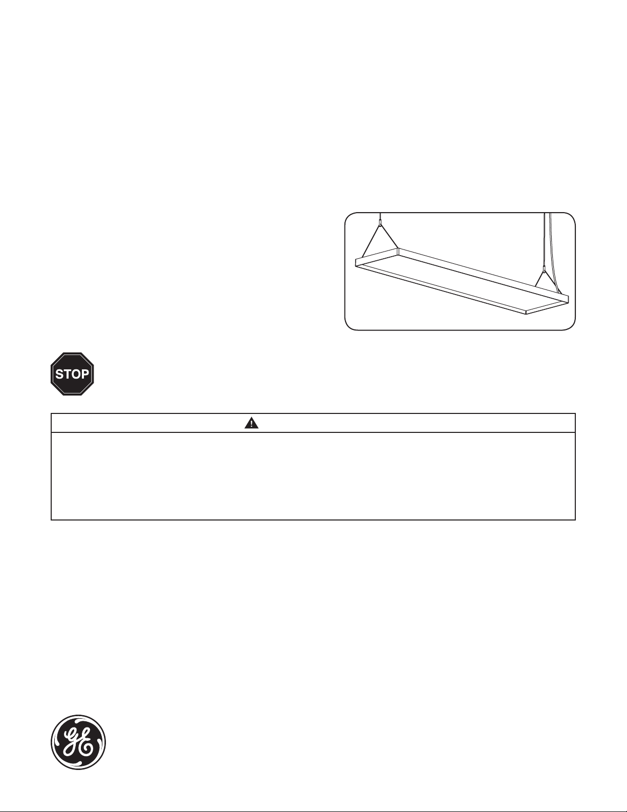
Suspended LED Fixture
(Series EP14)
Features
• Long life (50,000 hour rated life)
• 5 year warranty
• IP30
• Dry location rated
BEFORE YOU BEGIN
Read these instructions completely and carefully.
WARNING/AVERTISSEMENT
RISK OF ELECTRIC SHOCK
• Turn power off before inspection, installation or removal.
• Properly ground electrical enclosure.
RISK OF FIRE
• Follow all IEC and local codes.
• Use only UL or IEC approved wire for input/output connections.
Minimum size 18 AWG (0.82mm2).
Save These Instructions
Use only in the manner intended by the manufacturer. If you have any questions, contact the manufacturer.
RISQUES DE DÉCHARGES ÉLECTRIQUES
• Coupez l’alimentation avant d’’inspecter, installer ou déplacer le luminaire.
• Assurez-vous de correctement mettre à la terre le boîtier d’alimentation
électrique.
RISQUES D’INCENDIE
• Respectez tous les codes IEC et codes locaux.
• N’utilisez que des ls approuvés par UL ou IEC pour les entrées/sorties de
connexion. Taille minimum 18 AWG (0.82mm2).
imagination at work
Page 2
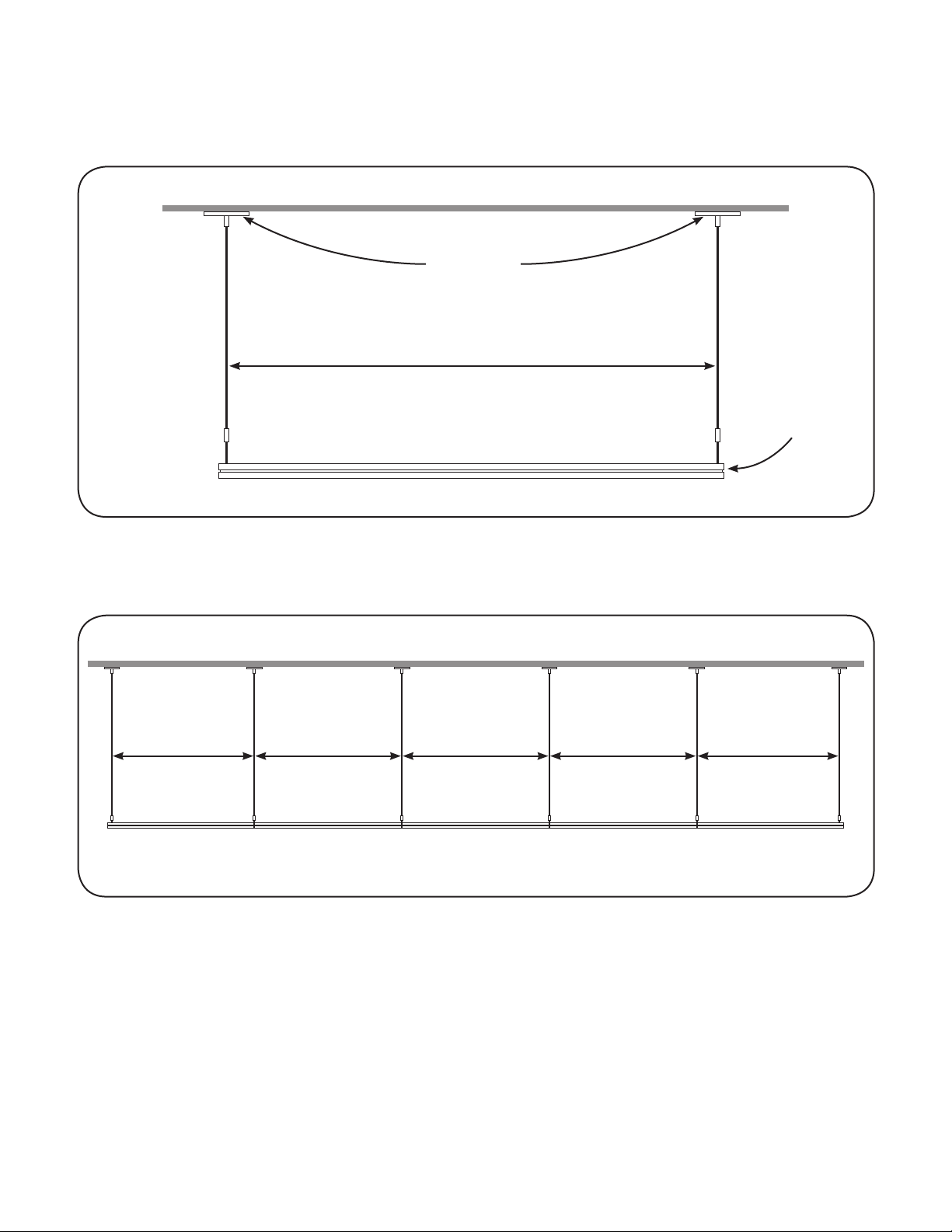
Dene Distance Between Canopy Sets
Single unit installation scenario:
1179mm (46.4 in.)
(distance between canopy sets)
Canopy set
Luminaire
Multiple units in series installation scenario:
1193mm (47 in.) 1207mm (47.5 in.) 1207mm (47.5 in.) 1207mm (47.5 in.) 1193mm (47 in.)
1st luminaire 2nd luminaire 3rd luminaire 4th luminaire 5th luminaire
Distance between canopy sets for left and right luminaires = 1193mm (47 in.)
Distance between canopy sets for luminaires in the middle = 1207mm (47.5 in.)
Example: To install ve units in series, the distance between canopy sets for the 1st (left) and 5th (right) luminaire is
1193mm (47 in.), and the distance between canopy sets for the 2nd, 3rd and 4th (middle) luminaires is 1207mm (47.5 in.).
Page 3

Unit Installation
Carefully unpack unit from its packaging. Properly
1
inspect for defects before installing. Wear work
gloves to prevent dirt and oil from being transferred
to the luminaire.
To driver enclosure
To driver enclosure
Attach bracket bar to junction box in ceiling with
2
Junction box in ceiling
two 8-32 (M4) screws. Repeat on other side.
Bracket bar
Canopy
(electrical)
Strain relief
bushing
Wires from luminaire
Connect the black (line) and white (neutral) wires
3
from the luminaire to the matching-colored wires
from the driver enclosure. Connect both green
wires to the grounding screw.
Squeeze tip to adjust
Stud
Cable coupler
Suspension cable
Fit canopy over stud of bracket bar, then screw
4
cable coupler onto stud.
Tie wrap
To adjust height and to level a xture, squeeze the
5
tip of the gripper and pull the suspension cable to
the desired height. Clip the cable with cable cutters
to nish the appearance.
Optional: For an improved appearance, electrical
6
wire can be tie-wrapped to the suspension wire.
Page 4

Optional Mounting Method - Connecting Suspended Fixtures in Series
Canopy set without power cable
Canopy sets with power cable
For multiple units installed in series, all canopy sets will have a power cable except the last canopy.
1
Disconnect
suspension wire
1st luminaire
On the 1st luminaire, disconnect the right-side
2
suspension wire and “Y” shape suspension wire.
Then on the 2nd luminaire, disassemble the
left-side “Y” shape suspension wire (this one will
not be used).
Remove “Y” shape wires
2nd luminaire
“Y” shape
suspension wire
Attach a bracket to each end of the “Y” shape
3
suspension wire using washer, spring washer
and M8 nuts. Screw torque should be between
15.3±0.8kg f.
Squeeze tip to adjust
Bracket
Join 1st and 2nd luminaires together by fastening
4
the brackets on the modied “Y” shape suspension
wire from Step 9. Fasten brackets using four
M8 screws. Screw torque should be between
15.3±0.8kg f.
Reattach suspension wire to “Y” shape suspension
5
wire. To adjust height and to level a xture, squeeze
the tip of the gripper and pull the suspension cable
to the desired height. Clip the cable with cable
cutters to nish the appearance.
Page 5

Electrical Connections
Remove cover
Install ttings
Remove driver enclosure cover. Carefully remove
1
knockout for AC line input wires. Install listed
electrical ttings in the knockout holes for wire
protection.
AC line
From
luminaire
To dimming
controller (optional)
Connect the black (line), white (neutral) and green
3 4
wires of the AC line to the terminal block. Next
connect the red, blue and green wires of the
luminaire to the terminal block.
1/4-20 screws
Install driver enclosure to a suitable structural
2
member using two 1/4-20 screws.
Replace electrical enclosure cover. Remove
protective lm from the face of the luminaire.
Optional dimmer: When connecting dimming
controller, wires must be run through a separate
knockout hole equipped with cable gland suitable
for 20mm hole and separated a minimum of
6.4mm (0.250 in.) from branch circuit wiring.
Page 6

Maximum Driver Remote Mounting Distance
Supply Wire Gauge Wire Length*
18 AWG (0.82 mm2) 59.0 ft. (18 m)
16 AWG (1.31 mm2) 98.4 ft. (30 m)
14 AWG (2.08 mm2) 154.2 ft. (47 m)
12 AWG (3.31 mm2) 249.3 ft. (76 m)
* Includes xture’s 6.6 ft. (2.0 m) power cord
Specications
Input Voltage (VAC) 120 – 277V
Input Power (W) 55W
Input Frequency (Hz) 50/60 Hz
Power Factor > 0.9
THD < 20%
Control 0-10V & DALI
Ceilings Cable Suspension System
Warranty 5 years
Dimensions 47.5 in. x 11.8 in. x 1.38 in. (1206 mm x 299 mm x 35 mm)
Light Fixture Weight 14.3 lbs. (6.5 kg)
Environmental Operating Temperature Range -10°C to +40°C
Environmental Humidity (non-condensing) 20 to 80% Non-condensing, dry location rated
Environmental Storage Temperature Range -40°C to +60°C
IP Rating IP30
Conforms to the following standards:
GE Lighting Solutions • 1-888-MY-GE-LED • www.gelightingsolutions.com
1 - 8 8 8 - 6 9 - 4 3 - 5 3 3
GE Lighting Solutions, LLC is a subsidiary of the General Electric Company. Lumination is a trademark of GE Lighting Solutions, LLC. The GE brand and logo are trademarks of the General Electric Company.
© 2012 GE Lighting Solutions, LLC. Information provided is subject to change without notice. All values are design or typical values when measured under laboratory conditions.
IND027-112712
 Loading...