

Page 1

GE
Industrial Solutions
DEH-41 641 - EPP 2014
™
EntelliGuard L
Power Circuit Breaker
Disjuntor Caixa Aberta
Wyłączniki mocy
Installation, Operation and Maintenance Manual
Manual de Instalação, Operação e Manutenção
Instrukcja instalacji, obsługi i konserwacji
www.ge.com/ex/industrialsolutions
www.ge.com/eu/industrialsolutions
www.geindustrial.com.br
GE imagination at work
English
Português
Polski
Page 2
EntelliGuard L
INTRO BREAKER ACCESSORIES TESTS APPENDIX
LOCKS
TRIP UNIT
Caution! Important Requirements!
WARNING
WARNING
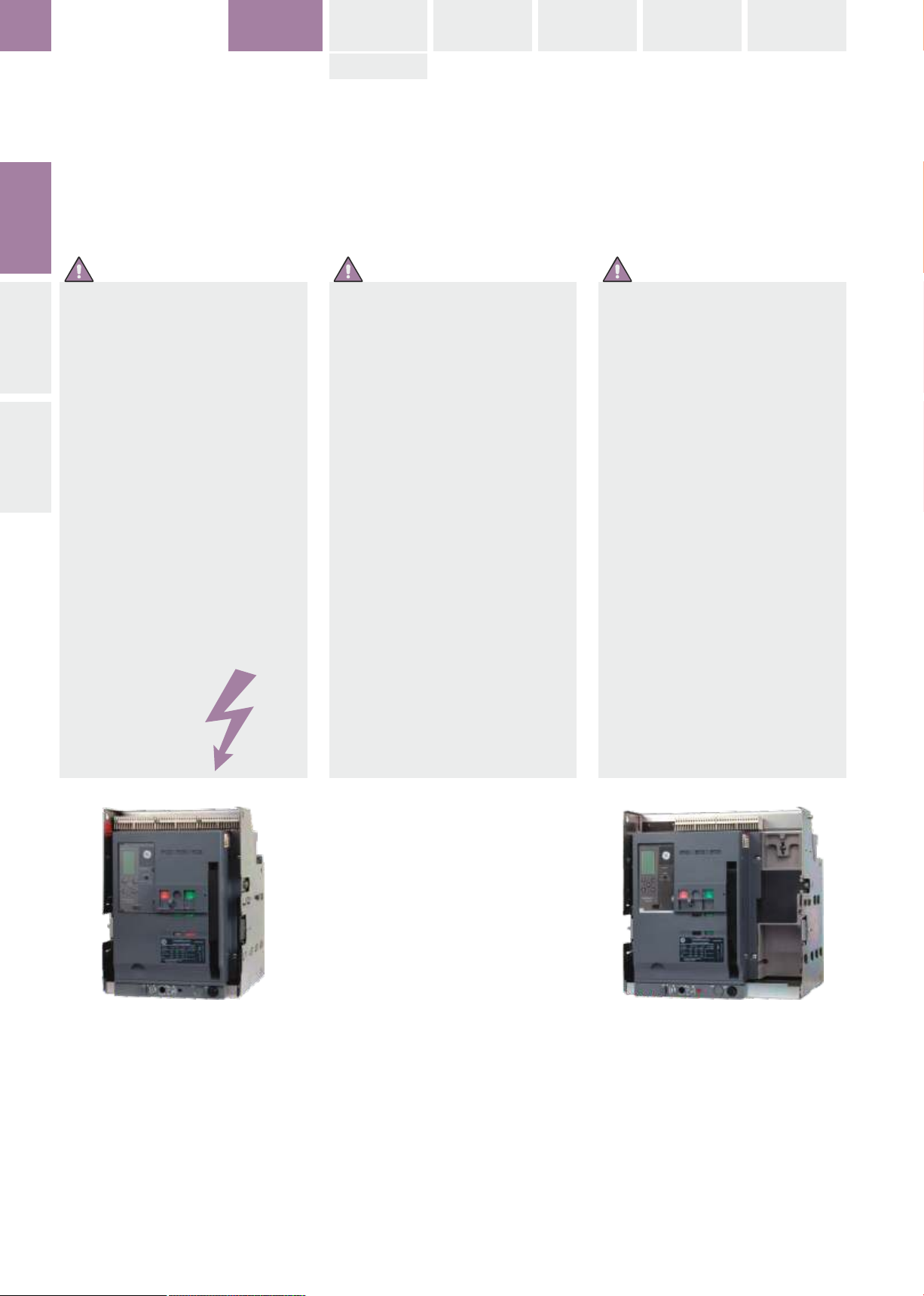
During operation the device described
in this manual is connected to high and
potentially dangerous voltages.
HINTSCONTENT
When the circuit breaker is switching
high currents, especially short-circuit
currents, hot and ionized gas may be
emitted.
Only qualified personnel are allowed to
install, commission, maintain or modify
this device in accordance with relevant
safety requirements.
The Circuit Breaker must be equipped
with the appropriate covers and/or be
installed in a suitable enclosure or panel
taking the required safety clearances
into account.
Non Compliance with these
requirements could result in damage to
property and/or severe injury to
personnel.
Cuidado!
Requisitos Importantes!
AVISO
Durante a operação do dispositivo
descrito neste manual, este está ligado
a tensões altas e potencialmente
perigosas.
Quando o disjuntor abre ou fecha
correntes de grande intensidade,
especialmente as correntes de curtocircuito, pode ser emitido gás quente e
ionizado.
Somente pessoas qualificadas podem
instalar, comissionar, manter ou alterar
este dispositivo, em conformidade com
os requisitos de segurança pertinentes.
O disjuntor deve ser equipado com as
coberturas apropriadas e / ou ser
instalado numa caixa apropriada ou em
painel tomando as distâncias de
segurança necessárias em conta.
O não cumprimento destes requisitos
pode resultar em danos à propriedade e
/ ou ferimentos graves para o pessoal.
Uwaga! Ważne zalecenia!
OSTRZEŻENIE
Aparaty opisane w tej instrukcji podczas
eksploatacji są podłączone do
wysokich, potencjalnie niebezpiecznych
napięć.
Na skutek rozłączania znacznych
prądów, zwłaszcza prądów
zwarciowych może dochodzić do emisji
gorących i zjonizowanych gazów.
Instalację, uruchomienie, konserwację i
modyfikację aparatów może
wykonywać tylko odpowiednio
przeszkolony personel, zgodnie z
wymogami bezpieczeństwa.
Wyłącznik należy zaopatrzyć w
odpowiednie osłony i/lub zainstalować
w obudowie lub rozdzielnicy, z
zastosowaniem odpowiednich
odstępów izolacyjnych.
Nieprzestrzeganie powyższych zasad
może doprowadzić do strat
materialnych i/lub poważnych obrażeń
personelu.
Read this manual and please retain for
future use.
Leia este manual e por favor guarde-o
para uso futuro.
Prosimy o dokładne przeczytanie instrukcji
i zachowanie jej na przyszłość.
Page 3

INTRO
EntelliGuard L
1.0
1.0 GENERAL INFORMATION
Installation, Operation and Maintenance Manual
EntelliGuard L Power Circuit Breaker
HAZARD CATEGORIES
The following important highlighted information
appears throughout this document to warn of
potential hazards or to call attention to
information that clarifies a procedure.
Carefully read all instructions and become
familiar with the devices before trying to install,
operate, service or maintain this equipment.
DANGER | PERIGO | NIEBEZPIECZEŃSTWO
Indicates a hazardous situation which, if not
avoided, could result in death or serious injury.
CAUTION: Failure to comply with these
instructions may result in product damage.
NOTICE: An aid meant to assist the user in
performing the set task. Please retain for future
use.
1.0 INFORMAÇÃO GERAL
Manual de Instalação, Operação e Manutenção
EntelliGuard L Disjuntor Caixa Aberta
CATEGORIAS DE PERIGO
A informação importante seguinte destacada
aparece ao longo deste documento para alertar
sobre riscos potenciais ou para chamar a
atenção para as informações que esclarece um
determinado procedimento.
Leia atentamente todas as instruções e para se
familiarizar com os dispositivos antes de tentar
instalar, operar, efetuar um serviço ou
manutenção deste equipamento.
Indica uma situação perigosa que, se não for
evitada, pode resultar em morte ou ferimentos
graves.
ATENÇÃO: O descumprimento destas
instruções pode resultar em danos ao produto.
AVISO: Uma ajuda destinada a auxiliar o
utilizador na execução da tarefa definida. Por
favor, guarde para uso futuro.
1.0 INFORMACJE OGÓLNE
Instrukcja instalacji, obsługi i konserwacji
Wyłączniki EntelliGuard L
RODZAJE ZAGROŻEŃ
Ważne informacje, w tym ostrzeżenia o
zagrożeniach i wyjaśnienia zasad obsługi są
zaznaczone kolorową i/lub pogrubioną czcionką.
Przed rozpoczęciem instalacji, użytkowania i
konserwacji należy dokładnie przeczytać całą
instrukcję i zapoznać się z urządzeniem.
Oznacza poważne niebezpieczeństwo,
niewłaściwe postępowanie grozi poważnymi
obrażeniami lub śmiercią.
UWAGA: Postępowanie niezgodne z
zaleceniami oznaczonymi w ten sposób może
doprowadzić do uszkodzenia urządzenia.
WAŻNE: Oznacza ważną informację
ułatwiającą wykonanie danej czynności.
Zalecane jest zachowanie jej na przyszłość.
HINTS
TRADEMARKS
EntelliGuard L
EntelliGuard GT-L
WARRANTY
This document is based on information available
at the time of its publication.
While efforts have been made to ensure
accuracy, the information contained herein does
not cover all details or variations in hardware
and software, nor does it provide for every
possible contingency in connection with
installation, operation, and maintenance.
Features may be described herein that are not
present in all hardware and software systems.
GE assumes no obligation of notice to holders of
this document with respect to changes
subsequently made.
GE makes no representation or warranty,
expressed, implied, or statutory, with respect to,
and assumes no responsibility for the accuracy,
completeness, sufficiency, or usefulness of the
information contained herein.
No warrantees of merchantability or fitness for
purpose shall apply.
Contact your local sales office if further
information is required concerning any aspect of
EntelliGuard L circuit breaker operation or
maintenance.
MARCAS
EntelliGuard L
EntelliGuard GT-L
GARANTIA
Este documento é baseado em informações
disponíveis no momento da sua publicação.
Embora esforços tenham sido feitos para
assegurar a exatidão, as informações aqui
contidas não cobrem todos os detalhes ou
variações de hardware e software, nem se
prevêem todas as contingências possíveis
relacionadas com a instalação, operação e
manutenção.
Podem ser descritas características neste
documento que não estão presentes em todos
os sistemas de hardware e software.
GE Energy não assume qualquer obrigação de
notificação aos titulares deste documento no
que diz respeito às alterações posteriormente
introduzidas.
GE Energy não faz nenhuma representação ou
garantia expressa, implícita, ou estatutária, com
relação a, e não assume nenhuma
responsabilidade pela precisão, complitude,
suficiência, ou utilidade das informações aqui
contidas.
Nenhuma garantia de comerciabilidade ou
adequação a um fim é aplicável.
Contate seu representante local de vendas, se
são necessárias informações complementares
sobre qualquer aspecto do funcionamento do
disjuntor EntelliGuard L ou para manutenção.
ZNAKI HANDLOWE
EntelliGuard L
EntelliGuard GT-L
GWARANCJA
Niniejszy dokument został opracowany na
podstawie informacji aktualnych w czasie
przygotowania do publikacji.
Pomimo dołożenia wszelkich starań, aby
publikowane dane były możliwie dokładne i
szczegółowe - nie możemy zagwarantować że
obejmują one wszystkie szczegóły lub możliwe
wersje urządzeń lub oprogramowania oraz że
zapewniają zgodność pod względem instalacji,
obsługi i konserwacji.
Możliwe jest, że cechy opisane tutaj mogą nie
występować w urządzeniach lub
oprogramowaniu.
GE nie ponosi odpowiedzialności wobec
użytkowników niniejszego dokumentu za zmiany
wprowadzone po jego publikacji.
GE nie gwarantuje, zarówno bezpośrednio jak i w
sposób dorozumiany lub prawny, a także nie
ponosi odpowiedzialności za dokładność,
kompletność, wystarczalność lub użyteczność
informacji zawartych w niniejszej instrukcji.
Nie mają zastosowania jakiekolwiek gwarancje
cech użytkowych urządzenia lub jego
przydatności do określonego celu.
Dodatkowe informacje dotyczące szczegółów
użytkowania lub konserwacji i serwisu
wyłączników EntelliGuard L można uzyskać w
lokalnym biurze sprzedaży GE.
1.0-01
Page 4

EntelliGuard L
INTRO BREAKER ACCESSORIES TESTS APPENDIX
LOCKS
TRIP UNIT
CONTENT
WARNING
--------------------------------------------------------
1.0 - GENERAL INFORMATION
--------------------------------------------------------
1.1.0 Introduction
Quality Assurance
Options Check Sheet
HINTSCONTENT
Product Serial & Catalogue Number
1.1.1 Short Product Description
1.1.2 Features and Characteristics
1.1.3 Storage
1.1.4 Rating label description
1.1.5 Tools Needed for Installation
--------------------------------------------------------
1.2 - PRODUCT SPECIFICATIONS
- Tables
--------------------------------------------------------
1.3 - INSTALLATION
CONTEÚDO
--------------------------------------------------------
1.0 - INFORMAÇÕES GERAIS
--------------------------------------------------------
1.1.0 Introdução
Garantia de Qualidade
Folha de Verificação de Opções
Número de Série do Produto e Número de
Catálogo
1.1.1 Descrição resumida do produto
1.1.2 Características e funcionalidades
1.1.3 Armazenamento
1.1.4 Descrição dos dados da etiqueta frontal
1.1.5 Ferramentas necessárias para instalação
--------------------------------------------------------
1.2 - ESPECIFICAÇÕES DO PRODUTO
- Tabelas
--------------------------------------------------------
1.3 - INSTALAÇÃO
SPIS TREŚCI
--------------------------------------------------------
1.0 - INFORMACJE OGÓLNE
--------------------------------------------------------
1.1.0 Wprowadzenie
Zapewnienie jakości
Specyfikacja techniczna dostawy
Numer seryjny i Numer katalogowy produktu
Jednostki miar
1.1.1 Krótki opis urządzenia
1.1.2 Cechy i charakterystyka
1.1.3 Przechowywanie
1.1.4 Tabliczka znamionowa
1.1.5 Narzędzia niezbędne do instalacji
--------------------------------------------------------
1.2 - DANE TECHNICZNE
- Tabele
--------------------------------------------------------
1.3 - INSTALACJA
1.3.1 Lifting and Mounting
Lifting / Hoisting beams
Handling, Mounting and Connecting
Heat Dissipation, Watt loss, Temperatures
Clearances
1.3.2 Fixed-Pattern Circuit Breaker
1.3.3 Drawout Pattern Circuit Breaker
Removal from Cassette
Mounting in Cassette
1.3.4 Secondary Disconnect Terminal Blocks
Location
Use
General schematics
Definition of connected devices
to Block B, C and Block D
--------------------------------------------------------
1.4 - OPERATION
1.4.1 Charging of Main Springs
Manually
Electrically
1.4.2 Sequence of breaker operation
1.4.3 Circuit breaker closing operation
1.4.4 Circuit breaker opening operation
1.4.5 Circuit breaker Withdrawal
1.4.6 Circuit breaker Insertion/Cassette
1.4.7 Sequence of operation cassette
--------------------------------------------------------
2.0 - TRIP UNIT
General Information
1.3.1 Içamento e montagem
Vigas de Elevação/Içamento
Manuseio, Montagem e Conexão
Dissipação térmica, perda de potência,
temperaturas, Espaçamento
1.3.2 Instalação do Disjuntor Fixo
1.3.3 Instalação do Disjuntor Extraível
Retirar do Chassi
Montagem no Chassi
1.3.4 Blocos de terminais secundários
Localização
Uso
Esquemas Gerais
Definição dos dispositivos conectados ao
bloco A, B & C
--------------------------------------------------------
1.4 - OPERAÇÃO
1.4.1 Carregamento das Molas Principais
Manualmente
Elétricamente
1.4.2 Sequência de operação do disjuntor
1.4.3 Operação de fechamento do disjuntor
1.4.4 Operação de abertura do disjuntor
1.4.5 Retirada do disjuntor extraível
1.4.6 Inserção do disjuntor no chassi
1.4.7 Sequência de operações no chassi
--------------------------------------------------------
2.0 – Unidade de disparo
Informação Geral
1.3.1 Podnoszenie i zamocowanie
Podnoszenie / belki dźwigowe
Transport , montaż, podłączenie
Rozpraszanie ciepła, straty mocy, wartości
temperatury, Odstępy izolacyjne
1.3.2 Wyłącznik stacjonarny
1.3.3 Wyłącznik wysuwny
Wyjęcie z podstawy
Włożenie do podstawy
1.3.4 Listwy przyłączeniowe (zaciskowe) dla
obwodów pomocniczych
Lokalizacja
Zastosowanie
Schematy ogólne
Urządzenia podłączane do listw
zaciskowych B i C oraz listwy D
--------------------------------------------------------
1.4 - OBSŁUGA
1.4.1 Zbrojenie (naciągnięcie sprężyn napędu)
Ręczne
Elektryczne
1.4.2 Kolejność operacji
1.4.3 Zamykanie wyłącznika
1.4.4 Otwieranie wyłącznika
1.4.5 Wysuwanie wyłącznika
1.4.6 Wsuwanie wyłącznika
1.4.7 Położenia wyłącznika wysuwnego w
podstawie
--------------------------------------------------------
2.0 - WYZWALACZ NADPRĄDOWY
Informacje ogólne
2.1 Product description
2.2 Operation
2.3 LCD Screen Mode
2.4 Curves
2.5 Time-Current Curves
2.6 Installation
2.7 Connection scheme
2.8 Troubleshooting
2.9 Catalogue code build
1.0-02
2.1 Descrição do Produto
2.2 Operação
2.3 Modo de Tela LCD
2.4 Curvas
2.5 Curva tempo-corrente
2.6 Instalação
2.7 Esquema de ligação
2.8 Solução de Problemas
2.9 Construção do código de catálogo
2.1 Opis wyzwalacza
2.2 Obsługa
2.3 Tryby pracy wyświetlacza LCD
2.4 Charakterystyki
2.5 Charakterystyki czasowo-prądowe
2.6 Instalacja / podłączenie
2.7 Schematy połączeń
2.8 Usuwanie usterek
2.9 Budowa numeru katalogowego
Page 5

INTRO
EntelliGuard L
1
--------------------------------------------------------
3.0 - LOCKS AND INTERLOCKS
3.1 Circuit breaker front panel
- Breaker Security Padlocking
- Breaker Security Keylocking
- Pushbutton Padlocking
3.2 Drawout Breaker Cassette
- Cassette Security Keylocking
- Racking handle access Padlocking
- Standard Drawout Breaker Interlock
- Mis insertion device (Interlock)
- Door interlock
3.3 Interlocking of Multiple Breakers
3.4 Tables Locking options
--------------------------------------------------------
4.0 - ACCESSORIES DESCRIPTION
General Information
4.1 Releases / Coils
4.2 Electrical Charging Motor
4.3 Contacts
4.4 Installation parts
4.5 Other Accessories
4.6 Spare parts
--------------------------------------------------------
5.0 - MAINTENANCE, TESTING AND
TROUBLESHOOTING
--------------------------------------------------------
3.0 – SEGURANÇA E Intertravamentos
3.1 Painel frontal do disjuntor
- Bloqueio por cadeado
- Bloqueio por fechadura
- Bloqueio de botões
3.2 Chassi do Disjuntor Extraível
- Cadeado de acesso à manivela de
extração
- Cadeado da manivela de extração
- Fechadura de Segurança do Chassi
- Dispositivo mal inserido (intertravamento)
- Intertravamento de Porta
3.3 Intertravando múltiplos Disjuntores
3.4 Tabelas de opções de bloqueio
--------------------------------------------------------
4.0 – DESCRIÇÃO DOS ACESSÓRIOS
Informação Geral
4.1 Disparos / Bobinas
4.2 Motor de carregamento elétrico
4.3 Contatos
4.4 Peças de instalação
4.5 Acessórios
4.6 Peças sobressalentes
--------------------------------------------------------
5.0 – MANUTENÇÃO, TESTE E Solução DE
PROBLEMAS
--------------------------------------------------------
3.0 - ZAMKI I BLOKADY MECHANICZNE
3.1 Płyta czołowa wyłącznika
- Blokady bezpieczeństwa zamykane na kłódkę
- Blokady bezpieczeństwa zamykane na klucz
- Blokowanie przycisków przy użyciu kłódek
3.2 Podstawy wyłączników wysuwnych
- Zamki na klucz w podstawie
- Blokada dostępu do korby
- Standardowe blokady wyłącznika
wysuwnego
- Blokada ze sworzniami
- Blokada drzwi
3.3 Blokady między wyłącznikami
3.4 Rodzaje blokad - tabela
--------------------------------------------------------
4.0 - OPIS WYPOSAŻENIA
Informacje ogólne
4.1 Cewki / wyzwalacze pomocnicze
4.2 Napęd silnikowy
4.3 Styki / łączniki pomocnicze
4.4 Instalacja
4.5 Wyposażenie
4.6 Części zamienne
--------------------------------------------------------
5.0 - KONSERWACJA, TESTY I USUWANIE
USTEREK
CONTENT
5.1 Maintenance
- Inspection Schedule
5.2 Cleaning Procedure
- Arcing Contacts Inspection
- Circuit Breaker Main Mechanism
Inspection
5.3 Cassette Inspection
5.4 Contact wear Inspection
5.5 Isolating Contacts (Drawout Type)
Inspection
5.6 Power Terminals and Busbar Inspection
5.7 Lubrication
5.8 Testing
- Trip Unit Testing
5.9 Troubleshooting
--------------------------------------------------------
6.0 - APPENDIX
6.1 Catalogue number description
6.2 Dimensions
6.3 Service
5.1 Manutenção
- Agenda de inspeção
5.2 Procedimento de limpeza
-Inspeção dos contatos de arco
- Inspeção do mecanismo principal do
disjuntor
5.3 Inspeção do Chassi
5.4 Inspeção ao Desgaste dos Contatos
5.5 Inspeção de Contatos de Isolamento
(Tipo Extraível)
5.6 Inspeção dos Terminais e Barramentos
5.7 Lubrificação
5.8 Testes
- Teste da unidade de disparo
5.9 Solução de problemas
--------------------------------------------------------
6.0 - APÊNDICE
6.1 Descrição do número de catálogo
6.2 Dimensões
6.3 Serviço
5.1 Konserwacja
- Przeglądy
5.2 Czyszczenie
- Sprawdzenie styków opalnych
- Sprawdzenie mechanizmu napędowego
wyłącznika
5.3 Sprawdzenie podstawy wyłącznika
5.4 Sprawdzenie wyzwalacza nadprądowego
5.5 Sprawdzenie zacisków szczękowych
(wyłączniki wysuwne)
5.6 Sprawdzenie przyłączy głównych i
szynowych
5.7 Smarowanie
5.8 Testowanie
- Testowanie wyzwalacza nadprądowego
5.9 Usuwanie usterek
--------------------------------------------------------
6.0 - ZAŁĄCZNIK
6.1 Opis numerów katalogowych
6.2 Wymiary
6.3 Serwis
1.0-03
Page 6

EntelliGuard L
INTRO BREAKER ACCESSORIES TESTS APPENDIX
LOCKS
TRIP UNIT
Content:
1.1.0 Introduction
1.1.1 Short Product Description
1.1.2 Features and Characteristics
1.1.3 Storage
1.1.4 Rating label description
INTRO
1.1.5 Tools Needed for Installation
Fig. 1.0: EntelliGuard L Front View
1) Installed accessory indicators
2) Electronic trip unit
3) Manual charging handle
4) ON and OFF buttons
5) Contact position indicator ON/OFF
6) Ready to close indicator
7) Mechanical spring charge indication
8) Operation counter
SPECIFICATIONINSTALLATIONOPERATIONTRIP UNIT
9) Slot to fix breaker key interlock
10) Mechanical position indicator
11) Racking handle pad lock
12) Racking handle
13) Catalogue code
Fig. 2.0: Advanced Microprocessor based trip Unit
1) LCD screen with following menu options:
Setup
Allows adjustment of values and settings of all
parameters
Meter
Ammeter present
Status
Breaker and Trip Unit position
Events
History of trip's with indication of fault reason, and level.
2) 4 setting and 1 enter key to access trip unit
functionality
3) Manual or automatic reset facility
4) RS 232 C in/output
Conteúdo:
1.1.0 Introdução
1.1.1 Descrição Resumidas do Produto
1.1.2 Características e Funcionalidades
1.1.3 Armazenamento
1.1.4 Descrição dos dados da etiqueta frontal
1.1.5 Ferramentas necessárias para a
instalação
Fig. 1.0: Vista Frontal EntelliGuard L
1) Indicador de Acessório
2) Unidade de Disparo Eletrônico
3) Alavanca de Carregamento Manual
4) Botões ON/OFF
5) Indicador de posição dos contatos ON/OFF
6) Indicador pronto para fechar
7) Indicador de carregamento da mola
8) Contador de operações
9) Abertura para fixar o bloqueio por chave do
disjuntor
10) Indicador de posição mecânica
11) Bloqueio da manivela de extração por cadeado
12) Manivela de extração
13) Código de catálogo
Fig. 2.0: Unidade de disparo
com microprocessador avançado
1) Tela de LCD com as seguintes opções de menu:
Setup
Permite ajuste de valores e configurações de todos os
parâmetros
Medida
Amperímetro presente
Status
Posição do disjuntor e unidade de disparo
Eventos
Histórico dos disparos com indicação da razão e nível
da falta.
2) Acesso a funcionalidade da unidade de disparo
através de 4 teclas direcionais e 1 tecla enter
3) Dispositivo de reset manual ou automático
4) Entrada/saída RS 232 C
Spis treści:
1.1.0 Wprowadzenie
1.1.1 Krótki opis urządzenia
1.1.2 Cechy i charakterystyka
1.1.3 Przechowywanie
1.1.4 Tabliczka znamionowa
1.1.5 Narzędzia niezbędne do instalacji
Fot. 1.0: EntelliGuard L - widok z przodu
1) Wskaźniki informujące o wyposażeniu
2) Elektroniczny wyzwalacz nadprądowy
3) Dźwignia ręcznego zbrojenia wyłącznika
4) Przyciski ON (ZAMKNIJ) i OFF (OTWÓRZ)
5) Wskaźnik położenia styków głównych ON/OFF
6) Wskaźnik gotowości do zamknięcia
7) Wskaźnik stanu zazbrojenia sprężyn
8) Licznik operacji
9) Otwór do blokady na klucz wyłącznika
10) Mechaniczny wskaźnik położenia
11) Blokada wsuwania korby napędu
12) Korba wsuwania
13) Numer katalogowy
Fot. 2.0: Zaawansowany mikroprocesorowy
wyzwalacz nadprądowy
1) Ekran główny z następującymi funkcjami:
Ustawienia
Pozwala wprowadzać wartości nastaw i parametry
pracy
Moduł pomiarowy
Wyświetla wszystkie mierzone wartości
Status
Aktualny stan wyłącznika i wyzwalacza
Zdarzenia
Historia pracy wyzwalacza z danymi o przyczynach
wyzwolenia (otwarcia) wyłącznika, wartościach
wyłączanych prądów, dostęp do rejestracji przebiegów
prądu.
2) 4 przyciski wyboru i jeden przycisk zatwierdzający
(enter) dla dostępu do pełnej funkcjonalności
wyzwalacza.
3) Ręczny lub automatyczny reset (odblokowanie)
wyzwalacza.
4) Gniazdo RS 232 C
Fig. 1.0
Fig. 1.0
1
2
3
4
5
6
7
8
9
10
11
12
13
Fig. 2.0
Fig. 2.0
1
2
3
4
1.1-00
Page 7

BREAKER
EntelliGuard L
1.1
1.1 INTRODUCTION
Quality Assurance
All EntelliGuard L circuit breakers have been
designed and manufactured to the highest
technical standards.
GE uses strict procedures ensuring that the
mentioned technical standards are met whilst
maintaining a first class product quality.
Options Check Sheet
Each circuit breaker comes with an options
check sheet that lists all optional features and
accessories included in the circuit breaker,
cassette and trip unit (if ordered)
Catalogue number description
see Appendix
Product Serial & Catalogue Number
When communicating with GE on any aspect of
this device please mention the serial number &
the global catalogue number.
The serial number is unique for each device,
whilst the catalogue number provides all
technical and configuration data.
These codes can be found on the front labels of
the device as indicated on page 1.1-05, 2-28.
1.1 INTRODUÇÃO
Garantia de Qualidade
Todos os disjuntores EntelliGuard L foram
concebidos e fabricados segundo os mais altos
padrões técnicos.
A GE utiliza procedimentos rigorosos garantindo
que as normas técnicas referidas sejam
satisfeitas, mantendo uma qualidade de produto
de primeira classe.
Folha de Verificação de Opções
Cada disjuntor vem com uma folha de
verificação de opções que lista todos os
dispositivos opcionais e acessórios incluídos no
disjuntor, chassi e unidade de disparo (se
encomendada)
Descrição da referência
ver APENDICE
Número de série do produto e número de
catálogo
Ao comunicar com a GE sobre qualquer aspecto
deste aparelho, favor mencionar o número de
série e referência.
O número de série é único para cada aparelho,
enquanto o número de catálogo fornece todos
os dados técnicos e de configuração.
Estes códigos podem ser encontrados nos
rótulos na frente do dispositivo, como indicado
na página 1.1-00, 2-28.
1.1 WPROWADZENIE
INTRO
Zapewnienie jakości
Wszystkie wyłączniki EntelliGuard L zostały
opracowane i są produkowane według najwyższych
standardów technicznych.
GE ściśle przestrzega procedur zapewniających
spełnienie norm i wymogów, z jednoczesnym
utrzymaniem najwyższej jakości produkcji.
Specyfikacja techniczna dostawy
Każdy wyłącznik jest dostarczany ze specyfikacją
techniczną, wyszczególniającą wszystkie
opcjonalne cechy i wyposażenie zainstalowane w
wyłączniku, jego podstawie i wyzwalaczu
nadprądowym (jeśli zostały zamówione).
Opis numeru katalogowego
patrz: Załącznik
Numer seryjny i Numer katalogowy produktu
Kontaktując się z GE w jakiejkolwiek sprawie
dotyczącej tego urządzenia prosimy podać numer
seryjny i globalny numer katalogowy.
Numer seryjny jest unikalny (jednoznaczny) dla
każdego urządzenia, natomiast numer katalogowy
zawiera wszystkie dane techniczne i konfiguracyjne.
Numery te można znaleźć na tabliczkach
znamionowych urządzenia (aparatu) według
wskazówek na stronie 1.1-00, 2-28.
1.1.1 Short Product description
The EntelliGuard L Air Circuit Breaker is an Air
Circuit Breaker designed to meet the IEC 609472/3 standards.
The device is designed for use in networks with
voltages up to 690V AC and to be fully selective
with other EntelliGuard L and GE Record Plus
Circuit Breakers.
It is available as 3 or 4 pole device with current
ratings from 400A up to 4000A.
As a breaker the EntelliGuard L can be equipped
the GT-L Electronic Trip Unit a available in 4
versions each having the same universal setting
interface and an LCD screen.
A Non Automatic (Switch Disconnector) version
(without trip unit) is also possible. Both Breaker
and Switch Disconnector types are available in a
Fixed or Drawout pattern.
EntelliGuard L devices offer a combination of
high interruption and short time current
withstand ratings and can be used in
applications as Mains, Coupler/Tie or feeder
breaker or switch disconnector.
1.1.1 Descrição Genérica do Produto
O Entelliguard L é um disjuntor caixa aberta
projetado para atender as normas IEC 609472/3.
O aparelho é projetado para uso em redes com
tensões até 690 Vca e para ser totalmente
seletivo com os disjuntores Entelliguard L e
Record Plus da GE.
Está disponível em 3 ou 4 pólos com níveis de
corrente de 400 A até 4000 A.
Sendo um disjuntor, o Entelliguard L pode ser
equipado com (uma das 4 versões da) a unidade
de disparo GT-L disponível em 4 versões, cada
uma tendo o mesmo tipo de interface universal
e uma tela LCD.
Uma versão não automática (interruptor
seccionador, sem unidade de disparo) também
existe. Tanto o disjuntor quanto o interruptor
estão disponíveis numa execução fixa ou
extraível.
Os aparelhos Entelliguard L oferecem uma
combinação de níveis de alta capacidade de
corte e corrente de curta duração suportada e
podem ser usados em aplicações como
disjuntor de entrada, acoplamento de
barramentos, alimentador e interruptor
seccionador.
1.1.1 Krótki opis
Wyłącznik EntelliGuard L jest wyłącznikiem
powietrznym, spełniającym normy IEC 60947 2/3.
Aparaty te są przeznaczone do stosowania w
sieciach zasilanych napięciem do 690V AC, do
selektywnej współpracy z innymi wyłącznikami
EntelliGuard L oraz Record Plus produkowanymi
przez GE.
Są produkowane w wersjach 3- i 4biegunowych, w dla prądów od 400A do 4000A.
W wyłącznikach EntelliGuard L stosowane są
elektroniczne wyzwalacze nadprądowe GT-L,
dostępne w 4 wersjach, posiadające identyczny
panel obsługowy z wyświetlaczem LCD.
Produkowana jest również wersja rozłącznikowa
aparatu (bez wyzwalacza nadprądowego).
Zarówno wyłączniki jak i rozłączniki są dostępne
w wykonaniu stacjonarnym i wysuwnym.
Wyłączniki EntelliGuard L łączą w sobie wysoką
zdolność wyłączania zwarć a także
krótkotrwałego wytrzymywania znacznych
prądów zwarciowych, mogą być stosowane w
liniach zasilających, jako wyłączniki główne lub
sprzęgające lub jako rozłączniki.
1.1-01
Page 8

EntelliGuard L
INTRO BREAKER ACCESSORIES TESTS APPENDIX
LOCKS
TRIP UNIT
1.1.2 Features and Characteristics
Standard and Optional Features
Rated Short Time Withstand Current::
Up to 65kA for 1 sec
INTRO
Short Circuit / Interruption Rating:
(Breaking Capacity Icu=Ics)
Up to 65kA at 500V & 40kA at 690V
Rated current:
The devices have a 100% normal current rating
up to an ambient temperature of 50°C in free air.
Connection of Power supply
SPECIFICATIONINSTALLATIONOPERATIONTRIP UNIT
EntelliGuard L devices can be fed from top or
bottom terminals.
Stored energy Mechanism:
An EntelliGuard L Air Circuit Breaker uses a
stored energy mechanism that can
be charged manually or electrically. For manual
charging the operating handle is used, a spring
charging motor supplied with an indication
contact can be added for electrical charging.
Device closing time is less than five half cycles.
Closing and opening can be initiated remotely or
via the front cover push buttons. An O-C-O cycle
is possible without recharging. The breaker
operating mechanism is trip-free and has an
integrated anti-pumping system.
1.1.2 Especificações e Características
Especificações Standard e opcionais
Corrente nominal de curta duração:
Até 65kA a 1 seg
Corrente nominal de curto-circuito /
Interrupção:
(Capacidade de interrupção Icu=Ics)
Até 65kA em 500V & 40kA em 690V
Corrente nominal:
Estes aparelhos consideram 100% da corrente
nominal até uma temperatura ambiente de 50°C
ao ar livre.
Ligação da Fonte de Alimentação
A entrada de corrente nos aparelhos
EntelliGuard L pode ser feita pelos terminais
superiores ou inferiores.
Mecanismos de acumulação de energia:
Um disjuntor EntelliGuard L usa um mecanismo
de acumulação de energia que pode ser
carregado eletricamente ou manualmente. Para
o carregamento manual é usado uma manivela
com punho, pode também ser fornecido um
motor de carregamento da mola. O tempo de
fechamento do aparelho é menor que cinco
meios ciclos.
O fechamento e abertura do aparelho podem
ser iniciados remotamente ou via as botoneiras
na face frontal. Um ciclo A-F-A é possível sem
recarga. O mecanismo de operação do disjuntor
é independente dos disparos e integra um
sistema anti-pumping.
1.1.2 Cechy i charakterystyka
Cechy standardowe i opcjonalne
Prąd znamionowy krótkotrwale
wytrzymywany:
Maks. 65kA przez 1 sek.
Znamionowy prąd zwarciowy wyłączalny
graniczny:
(Zdolność wyłączania zwarć)
Maks. 65kA przy 500V i 40kA przy 690V
Prąd znamionowy:
Obciążalność aparatów wynosi 100% prądu
znamionowego w temperaturze otoczenia do
50°C w otwartym powietrzu.
Kierunek zasilania
Zasilanie może być podłączone do zacisków
górnych lub dolnych.
Zasobnikowy mechanizm napędowy:
W wyłącznikach EntelliGuard L zastosowany jest
zasobnikowy (sprężynowy) mechanizm
napędowy, zbrojony ręcznie lub elektrycznie.
Zbrojenie ręczne odbywa się przy użyciu dźwigni,
do zbrojenia elektrycznego stosowany jest silnik
naciągający sprężyny, dostarczany z łącznikiem
sygnalizacji zazbrojenia. Czas zamykania nie
przekracza pięciu półokresów.
Zamykanie i otwieranie może być uruchomione
zdalnie lub przyciskami na płycie czołowej. Po
zazbrojeniu możliwe jest wykonanie cyklu
łączeniowego O-Z-O (otwarcie-zamknięcieotwarcie) bez dozbrajania. Mechanizm
napędowy wyłącznika jest sterowany
nadrzędnie przez wyzwalacz (mechanizm typu
"trip-free"), posiada wbudowany układ antypompujący.
Factory fitted -ORField installable accessories & trip Units.
Accessories common to all breaker envelopes
are available in two different versions.
-- 1. Factory Mounted units
-- 2. Field installable Units; will be supplied with
all necessary connection & Fixing hardware.
Coils/Releases:
EntelliGuard L devices have provisions for a
maximum of 3 coils.
See table in chapter 4 for possible combinations.
The shunt releases (ST) are continuously rated.
Undervoltage releases have a built in time delay
of up to 50 ms, an external time delay module is
available if longer time delays are required
(TDM). Closing coils are equipped with an antipumping mechanism.
Breaker / Main contact
Status: OPEN/CLOSED, ON/OFF indication is
provided on the front cover.
Motor operator:
Motor/gearbox unit; easily accessible.
Connection modes
The cassettes for the devices in drawout mode
are supplies with Universal connectors for rear
horizontal or vertical use, Horizontal connection
pads or Front connection pads.
Montagem em fábrica -OU- Acessórios
instaláveis em campo e Unidades de Disparo
Acessórios comuns a todos os tamanhos de
aparelhos estão disponíveis em duas versões
diferentes.
-- 1. Unidades montadas em Fábrica
-- 2. Unidades a montar em campo com
todas as ligações e fixações necessárias.
Bobinas:
Os aparelhos EntelliGuard admitem um máximo
de 3 bobinas.
Veja a tabela no capítulo 4 para combinações
possíveis. As bobinas de disparo (ST) permitem
alimentação contínua. As bobinas de mínima
tensão têm uma temporização incorporada de
até 50ms, existe um módulo de temporização
externo no caso de ser necessário um tempo
superior (TDM). As bobinas de fechamento são
equipadas com mecanismo anti-pumping.
Estado dos contatos principais do disjuntor
Estados: Indicação OPEN/CLOSED, ON/OFF é
exibida na cobertura frontal.
Motor de carregamento:
Unidade motor/caixa de molas; facilmente
acessível.
Modos de ligação
Os chassis para os dispositivos em modo
extraível são equipados com conectores
universais para uso traseiro, horizontal ou
vertical, além de tomadas de conexão horizontal
ou frontal.
Wyposażenie i wyzwalacze nadprądowe
fabryczne -LUBdo zabudowy w miejscu instalacji.
Wyposażenie wspólne dla wszystkich wielkości
wyłączników jest dostępne w dwóch różnych
wersjach.
-- 1. Podzespoły wbudowane fabrycznie
-- 2. Podzespoły do zabudowy w miejscu
instalacji, dostarczane ze wszystkimi
niezbędnymi elementami łączącymi i
mocującymi.
Cewki (wyzwalacze pomocnicze):
W aparatach EntelliGuard L zastosować
możnamaksymalnie 3 cewki (wyzwalacze
pomocnicze). Możliwe kombinacje cewek
przedstawiono w tabeli w rozdziale 4.
Wyzwalacze napięciowe (ST) mogą być
zasilanew sposób ciągły. Wyzwalacze
podnapięciowe posiadają wbudowaną zwłokę
czasową 50 milisekund, gdy wymagane są
dłuższe opóźnienia można zastosować
zewnętrzny moduł zwłoki czasowej (TDM). Cewki
zamykające są wyposażone w układ przeciwpompujący.
Wyłącznik / styki główne
Status: OTWARTE/ZAMKNIĘTE, wskaźnik
położenia styków (ON/OFF) znajduje się na płycie
czołowej.
Napęd silnikowy:
Silnik z przekładnią, o dużej wytrzymałości, łatwo
dostępny z zewnątrz.
Rodzaje przyłączy głównych
Podstawy dla wyłączników wysuwnych są
dostarczane z przyłączami uniwersalnymi do
podłączenia poziomego lub pionowego z tylu
1.1-02
Page 9

BREAKER
EntelliGuard L
1.1
Auxiliary contacts
2 available designs:
-- Power rated 3NO & 3NC (default)
-- Power rated, 4NO & 4NC
Breaker Status indicators:
Standard Indicators include:
-- The breaker status indicator shows the
condition of the main contacts (OPEN, CLOSED).
-- The status of the closing springs is indicated
as CHARGED or DISCHARGED.
-- Ready to close contact provides visible
indication/readiness for close operation.
-- The draw-out position indicator displays
whether the breaker is in the CONNECT, TEST or
DISCONNECT position.
Through-door racking:
The breaker racking mechanism is accessible
through the front door and permits safely
disconnecting/withdrawing the circuit breaker
without opening the door and exposing
personnel to live parts.
Padlocking devices:
EntelliGuard L Air Circuit Breakers are supplied
with several padlocking devices. The breaker in
fixed and draw-out pattern have a padlocking
facility for one padlock of 5-8 mm allowing the
breaker to be locked in its OFF position.
Facia Pushbutton Padlocking
Facilities:
To prevent un-authorized access to both the ON
and OFF push buttons on the breakers front
fascia, a padlock able push button cover can be
fixed to the breaker front fascia. 1 padlock of 5-8
mm can be used.
Key Locking mechanism
Multiple kits are available allowing the use of
Ronis, Profalux or Castell Key locks for the
Breaker to lock the device in OFF position.
Cassette Position indication contacts:
This optional cassette/substructure device
permits local or remote indication of the circuit
breaker status CONNECTED, TEST,
DISCONNECTED. (6 single-pole changeover
contacts are available).
IP54 covers:
Each EntelliGuard L Air Circuit Beaker is supplied
with a Door Frame that provides the installed
device with IP43. Optionally an extra cover is
available providing an IP54 rating.
Operations counter:
Provides a local record of the cumulative
number of completed breaker closing
operations.
Bell alarm contact:
A changeover contact that once fitted to the
breaker indicates if the breakers has tripped on
one of its protective functions (Electronic Trip
Unit). An interface on the Trip Unit front face
allows a Manual or Automatic breakers reset.
The Bell Alarm Contact will only permanently
change position when the Trip Unit is in Manual
mode.
The Trip unit has a function (trip reason and
Contatos auxiliares
2 desenhos disponíveis
-- Contatos 3NA+3NF (padrão)
-- Contatos 4NA+4NF
Indicadores de estado do disjuntor:
Indicadores padrão incluem:
-- O indicador de estado do disjuntor exibe a
condição dos contatos principais (ABERTO,
FECHADO).
-- O estado das molas de fechamento é exibido
como CARREGADA ou DESCARREGADA.
-- Contato pronto para fechar exibe
indicação/preparo visíveis para a operação de
fechamento.
-- O indicador da posição de extração exibe se
o disjuntor está na posição CONECTADO, TESTE
ou DESCONECTADO.
Extração através da porta:
O mecanismo de extração do disjuntor é
acessível através da porta frontal e permite com
segurança desconectar/extrair o disjuntor sem
abrir a porta e expor os funcionários a peças
energizadas durante o processo.
Dispositivos de bloqueio por cadeado:
Os disjuntores caixa aberta EntelliGuard L são
fornecidos com diversos dispositivos de bloqueio
por cadeado. O disjuntor de execução fixa ou
extraível tem uma dispositivo de bloqueio para
um cadeado de 5-8mm permitindo ao disjuntor
ser bloqueado na posição OFF.
Funções de bloqueio por cadeado dos botões
frontais:
Para prevenir acesso não autorizado aos botões
ON e OFF localizados na face frontal do
disjuntor, é possível instalar uma cobertura
trancável por cadeado na parte frontal do
disjuntor. Um cadeado de 5-8mm pode ser
usado.
Mecanismo de bloqueio por chave
Vários kits estão disponíveis permitindo o uso de
fechaduras Ronis, Profalux ou Castell para o
disjuntor com o fim de bloquear o dispositivo na
posição OFF.
Contatos de indicação da posição no chassi:
Este dispositivo opcional da chassi /
subestrutura permite indicação local ou remota
do estado do disjuntor CONECTADO, TESTE,
DESCONECTADO (conjuntos disponíveis de 3 ou 6
contatos comutadores unipolares).
Cobertura IP54:
Cada disjuntor EntelliGuard L é fornecido com
uma moldura de cobertura que providencia ao
aparelho instalado um grau de proteção IP43.
Opcionalmente uma cobertura extra está
disponível para obter um grau de proteção IP54.
Contador de operações:
Providencia o registro local do número
cumulativo de operações de fechamento
completas do disjuntor.
Contato de alarme:
Um contato comutador que uma vez inserido no
disjuntor, indica se o disjuntor disparou em uma
de suas funções de proteção (unidade eletrônica
de disparo). Uma interface na face frontal da
unidade de disparo permite o reset de
disjuntores automáticos e não automáticos. O
contato de alarme só mudará
permanentemente de posição quando a
unidade de disparo estiver em modo manual.
przyłączami poziomymi lub z przyłączami z
dostępem od przodu.
Styki pomocnicze
Dostępne są 2 zestawy styków
-- Obciążalne 3NO i 3NC (w standardzie)
-- Obciążalne 4NO i 4NC
Wskaźniki stanu wyłącznika:
-- Grupa standardowych wskaźników obejmuje
Wskaźnik stanu wyłącznika informuje o
położeniu styków głównych (OTWARTE,
ZAMKNIĘTE)
-- Wskaźnik zazbrojenia sprężyn sygnalizuje
ZAZBROJENIE lub ROZBROJENIE napędu
(sprężyny NACIĄGNIĘTE lub LUŹNE).
-- Styk gotowości do zamknięcia wizualnie
informuje, że wyłącznik jest gotowy do
zamknięcia.
-- Wskaźnik położenia w podstawie sygnalizuje,
kiedy wyłącznik jest w położeniu PRACA, PRÓBA
lub ODŁĄCZONY.
Wsuwanie bez otwierania drzwi:
Mechanizm wsuwania wyłącznika jest dostępny
poprzez drzwi rozdzielnicy, dzięki temu możliwe
jest bezpieczne odłączenie/wysuniecie
wyłącznika z podstawy bez otwierania drzwi
szafy i bez narażania personelu obsługi na
zetkniecie z elementami pod napięciem.
Blokady zamykane na kłódkę:
Wyłączniki EntelliGuard L mogą być dostarczane
z kilkoma różnego rodzaju blokadami.
Wyłączniki w wykonaniu stacjonarnym i
wysuwnym posiadają blokady z zaczepami dla
kłódek o średnicy klamry 5-8 mm, pozwalające
zablokować wyłącznik w pozycji otwartej (OFF).
Blokowanie dostępu do przycisków na płycie
czołowej:
Aby uniemożliwić dostęp osób
nieupoważnionych do przycisków ON i OFF na
płycie czołowej wyłącznika - można zastosować
osłonę przycisków z uchwytem do założenia
1 kłódki 5-8 mm, mocowanej do płyty czołowej.
Mechanizmy dla zamków na klucz
Można skorzystać z kilku mechanizmów do
zamków typu Ronis, Profalux lub Castell,
umożliwiających blokadę mechanizmu w pozycji
OFF (otwarty).
Styki sygnalizacji położenia w podstawie:
Są to opcjonalne styki do zdalnej lub lokalnej
sygnalizacji położenia części ruchomej
wyłącznika w podstawie lub ramie
konstrukcyjnej (możliwe są położenia: PRACA,
PRÓBA, ODŁĄCZONY).
(dostępne są zestawy zawierające 6
jednobiegunowych styków przełącznych).
Osłony IP54:
Każdy wyłącznik EntelliGuard L jest dostarczany
z kołnierzem (ramką) zakładanym na drzwiach
rozdzielnicy, o stopniu ochrony IP43.
Opcjonalnie dostępna jest osłona o stopniu
ochrony IP54.
Licznik operacji:
Umożliwia lokalny odczyt łącznej ilości pełnych
zamknięć wyłącznika.
Łącznik alarmowy:
Styk przełączny instalowany w wyłączniku,
sygnalizujący że został on otwarty (wyzwolony)
przez jedną z funkcji ochronnych
elektronicznego wyzwalacza nadprądowego.
Przełącznik w panelu obsługowym wyzwalacza
nadprądowego umożliwia włączenie Ręcznego
lub Automatycznego resetu (odblokowania).
Łącznik alarmowy zmienia swój stan na stale
wtedy, gdy w wyzwalaczu nadprądowym jest
INTRO
1.1-03
Page 10
EntelliGuard L
INTRO BREAKER ACCESSORIES TESTS APPENDIX
LOCKS
TRIP UNIT
event logger) that allows the user to establish
why the breaker has tripped.
Spring charged and ready to close contacts:
A breaker with electrical charging mechanism
INTRO
can be equipped with one of two indication
contacts.
The first the Spring Charged Contact simply does
as indicated and is supplied as a standard
accessory with all electrically operated breakers.
The second, the ready to close indication,
optionally replaces the Spring Charged Contact.
It only moves position when the following
conditions are met:
SPECIFICATIONINSTALLATIONOPERATIONTRIP UNIT
- The circuit breaker is open
- The closing springs are charged
- The circuit breaker is not locked/
interlocked in open position
- There is no standing closing order
- There is no standing opening order
Both contacts have a 1NO configuration.
1.1.3 Storage
Store circuit breakers and cassettes in a clean,
dry location in their original packaging.
A unidade de disparo conta com uma função
(razão do disparo e registro de eventos) que
permite ao usuário estabelecer a causa do
disparo do disjuntor.
Contatos de mola carregada e de preparado
para fecho:
Um disjuntor com mecanismo de carregamento
elétrico pode ser equipado com um de dois
contatos de indicação.
O primeiro, o contato de mola carregada, é
basicamente o que se indica e é fornecido como
um acessório padrão com todos os disjuntores
de comando motorizado.
O segundo, a indicação pronto para fechar,
opcionalmente substitui o contato de mola
carregada. Ele somente muda de posição
quando as seguintes condições são satisfeitas:
- O disjuntor está aberto
- As molas de fechamento estão carregadas
- O disjuntor não está bloqueado/intertravado
na posição aberta
- Não há um comando de fechamento pendente
- Não há um comando de abertura pendente
Ambos contatos tem uma configuração 1NA.
1.1.3 Armazenamento
Armazene os disjuntores e chassis num
ambiente limpo e seco dentro da sua
embalagem original
włączony reset Ręczny.
Wyzwalacz nadprądowy umożliwia
użytkownikowi ustalenie przyczyny wyzwolenia
(otwarcia) wyłącznika (rejestracja przyczyn
wyzwolenia i zdarzeń).
Styki sygnalizacji zazbrojenia i gotowości do
załączenia:
Wyłącznik z elektrycznym naciąganiem
(zbrojeniem) sprężyn mechanizmu napędowego
może być wyposażony w jeden lub dwa styki
sygnalizacyjne.
Pierwszy z nich, styk sygnalizacji zazbrojenia,
informuje o zazbrojeniu i jest dostarczany z
napędem silnikowym.
Drugi ze styków, sygnalizujący gotowość
wyłącznika do zamknięcia, opcjonalnie
zastępuje styk sygnalizacji zazbrojenia.
Zmienia on położenie, gdy spełnione są poniższe
warunki:
- Wyłącznik jest otwarty
- Sprężyny mechanizmu są naciągnięte
- Wyłącznik nie jest zablokowany w pozycji
otwartej
- Nie występuje stałe polecenie zamknięcia
- Nie występuje stałe polecenie otwarcia
Obydwa styki są dostępne w wersji NO.
1.1.3 Przechowywanie
Wyłączniki i podstawy należy przechowywać w
czystym, suchym pomieszczeniu, w ich
oryginalnym opakowaniu.
not es n ot as | no ta tk i
. . . . . . . . . . . . . . . . . . . . . . . . . .
. . . . . . . . . . . . . . . . . . . .
. . . . . . . . . . . . . . . . . . . .
. . . . . . . . . . . . . . . . . . . .
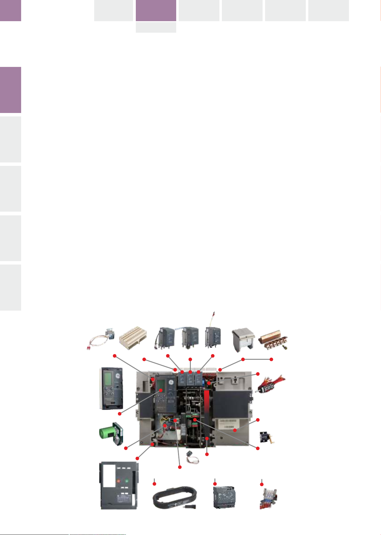
Bell Alarm
Contact
Secondary
Terminal Blocks
Undervoltage
Release
Closing CoilShunt Release
Arc chute Arcing Contacts
. . . . . . . . . . . . . . . . . . . . .
. . . . . . . . . . . . . . . . . . . . . . . .
Auxiliary
Contacts
. . . . . . . . . . . . . . . . . . . . . . . .
. . . . . . . . . . . . . . . . . . . . . . . .
. . . . . . . . . . . . . . . . . . . . . . . .
. . . . . . . . . . . . . . . . . . . . . . . . .
Trip Unit
Breaker
. . . . . . . . . . . . . . . . . . . . . . . . .
. . . . . . . . . . . . . . . . . . . . . . . . .
. . . . . . . . . . . . . . . . . . . . . . . . .
. . . . . . . . . . . . . . . . . . . . . . . . .
. . . . . . . . . . . . . . . . . . . . . . . . . . . . . . . . . . . . .
Motor operator
Breaker Front Cover
Ready to close
Contact
Spring charging handle
Operation
Counter
. . . . . . . . . . . . . . . . . . . . . . . . . . . . . . . . . . . . . . . . . . . .
. . . . . . . . . . . . . . . . . . . . . . . .
Rogowski Coil
Time Delay Module
Cassette Position
Indic. Contact
. . . . . . . . . . . . . . . . . . . . . . . .
. . . . . . . . . . . . . . . . . . . . . . . . . . . .
1.1-04
Page 11
BREAKER
EntelliGuard L
1.1
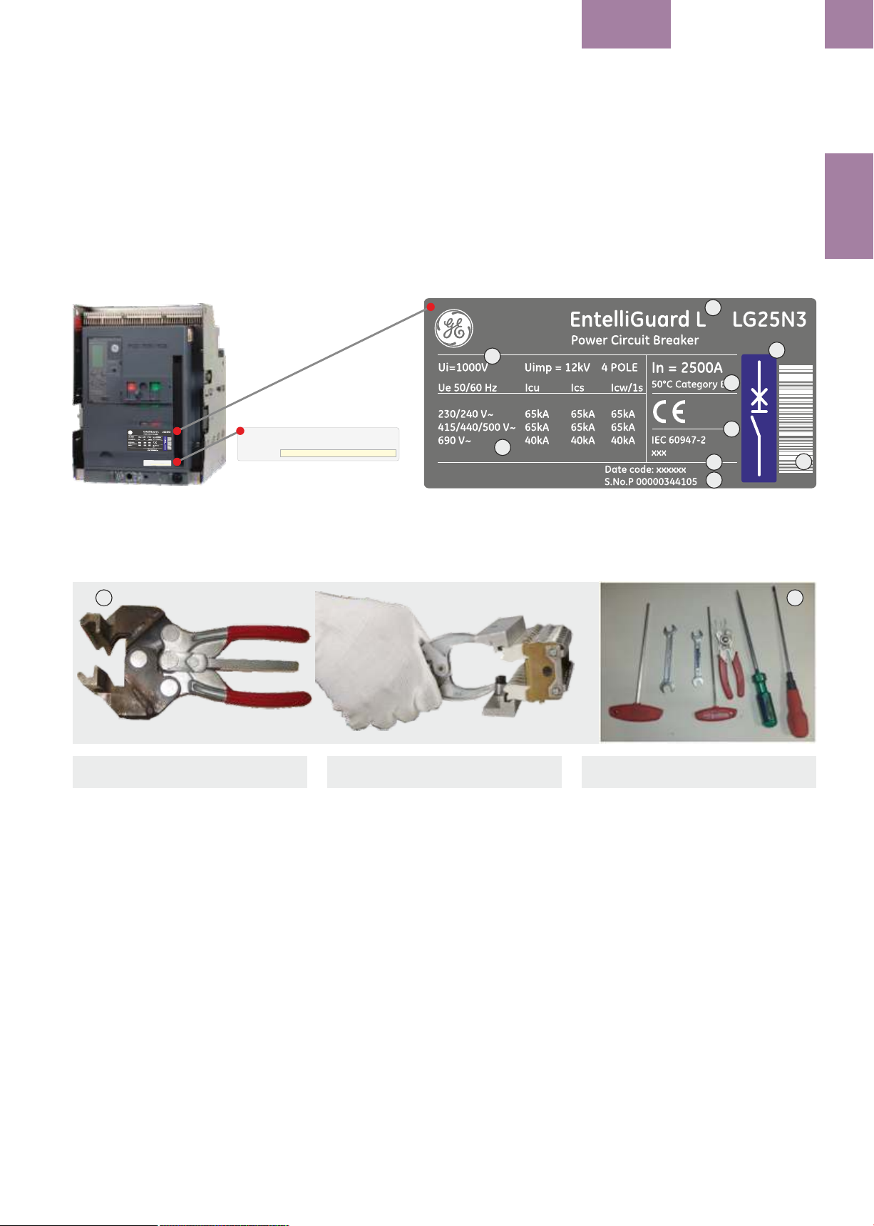
1.1.4 Front label data overview:
1. Product Denomination
2. Serial number
3. Colour Code indicating Interruption Tier
4. Voltage Ratings
5. Current Ratings
6. Certifications & Standards
7. Short Circuit Interruption data
8. Manufacturing Date
EntelliGuard L
EntelliGuard L
CA
T #
XXXXX
1.1.5 TOOLS needed for installation
Table 1.1 provides a list of the hand tools
required to install, operate and maintain the
EntelliGuard L Circuit Breaker.
®
1.1.4 Dados da etiqueta frontal:
1. Denominação do produto
2. Código de barras (com número de série)
3. Código de cores da capacidade de interrupção
4. Tensão nominal
5. Corrente nominal
6. Certificações e Normas
7. Dados da corrente nominal de interrupção de
curto-circuito
8. Data de fabricação
4
XXXXXCAT #
7
1.1.5 FERRAMENTAS necessárias para
a instalação
A tabela 1.1 indica a lista de ferramentas
manuais para instalar, operar e efetuar
manutenção ao Disjuntor EntelliGuard L.
®
1.1.4 Tabliczka znamionowa na płycie
czołowej:
1. Symbol aparatu
2. Kod paskowy
3. Kolor określający zdolność wyłączania
4. Napięcie znamionowe
5. Prąd znamionowy
6. Certyfikaty i spełniane normy
7. Zdolność wyłączania zwarć
8. Data produkcji
1
3
5
6
8
2
1.1.5 NARZĘDZIA niezbędne do
instalacji
Tabela 1.1 zawiera wykaz narzędzi ręcznych
wymaganych do zainstalowania, obsługi i
konserwacji wyłącznika EntelliGuard L.
®
INTRO
2
Table 1.1: Required Hand Tools Fig. B
Tool Name / Function
Cluster pliers (Fig. A)
To remove cluster contacts for inspection.
Screwdriver (8 mm flat):
To operate racking aperture shutter drive.
Allen key (5 mm):
To remove arc chutes for inspection and
maintenance. To remove or adjust fixed and
moving arcing contacts.
Allen key (4 mm):
To remove motor operator mounting screws.
Metric feeler gauges:
To check arcing contact gaps.
Pozidrive screwdriver (#2):
To remove mechanical and electronic
component mounting screws.
Pozidrive screwdriver (#3):
To remove front cover mounting screws.
Tabela 1.1: Ferramentas manuais necessárias
Nome da ferramenta / Função
Alicate para pinças de seccionamento (Fig. A)
Para remover as pinças de seccionamento ao
efetuar a inspeção.
Chave de parafusos (8 mm fendas):
Serve para operar a abertura dos obturadores
Chave Allen (5 mm):
Para remover as câmaras de extinção para
inspeção e manutenção. Serve para remover ou
ajustar os contatos de extinção fixos ou móveis
Chave Allen (4 mm):
Para os parafusos do motor de carregamento
elétrico.
Afinadores métricos:
Servem para comprovar e afinar o espaçamento
entre os contatos de extinção.
Chave Pozidrive (#2):
Para remover parafusos de montagem de
equipamentos mecânicos e eletrónicos.
Chave Pozidrive (#3):
Para remover os parafusos da cobertura frontal
BA
Tabela 1.1 Niezbędne narzędzia ręczne
Nazwa narzędzia / funkcja
Cęgi do zacisków szczękowych (Fig. A)
Umożliwiają zdejmowanie zacisków
szczękowych do przeglądu.
Wkrętak (płaski, 8mm)
Do przesuwania przesłony otworu dla korby w
mechanizmie wsuwania wyłącznika.
Klucz sześciokątny "Imbus" (5mm):
Służy do zdejmowania komór łukowych do
przeglądu i konserwacji. Do zdejmowania i
regulacji stałych i ruchomych styków opalnych.
Klucz sześciokątny "Imbus" (4mm):
Do odkręcania śrub mocujących napęd
silnikowy.
Szczelinomierze metryczne:
Do sprawdzania odstępu między stykami
opalnymi.
Wkrętak Pozi Drive (#2):
Do odkręcania wkrętów mocujących elementy
mechaniczne i elektroniczne. Do podłączania
przewodów do listew zaciskowych.
Wkrętak Pozi Drive (#3):
Do odkręcania wkrętów mocujących płytę
czołową.
1.1-05
Page 12

EntelliGuard L
INTRO BREAKER ACCESSORIES TESTS APPENDIX
LOCKS
TRIP UNIT
1.2 PRODUCT SPECIFICATIONS
Tables
INTRO
Content:
Table 1.1: Agency Certification
Table 1.2: Environmental Conditions
SPECIFICATIONINSTALLATIONOPERATIONTRIP UNIT
Table 1.6.A: IEC 60947 AC Version
50kA Performance Characteristics
Table 1.6.B: IEC 60947 AC Version
65kA Performance Characteristics
Table 1.9: Switch-Disconnector 42kA
Table 1.1: Agency Certification
(All industry standards referenced in this table are
the latest version at the time the product is sold.)
1.2 ESPECIFICAÇÕES DO
PRODUTO
Tabelas
Conteúdo:
Tabela 1.1: Certificações
Tabela 1.2: Condições ambientais
Tabela 1.6.A: IEC 60947, Performance e
características para versão 50kA
CA/CC
Tabela 1.6.B: IEC 60947, Performance e
características para versão 65kA
CA/CC
Tabela 1.9: Interruptor Seccionador 42kA
Tabela 1.1: Certificações
(Todas as normas do setor que figuram nesta
tabela correspondem à versão mais recente no
momento em que se comercializa o produto)
1.2 DANE TECHNICZNE
Tabele
Spis treści:
Tabela 1.1: Certyfikaty
Tabela 1.2: Warunki otoczenia
Tabela 1.6.A: Dane znamionowe wersji 50kA
AC/DC zgodnej z normą IEC 60947
Tabela 1.6.B: Dane znamionowe wersji 65kA
AC/DC zgodnej z normą IEC 60947
Tabela 1.9: Rozłączniki 42kA
Tabela 1.1: Certyfikaty
(Wszystkie normy branżowe/przemysłowe podane
w tej tabeli są w najnowszej wersji w czasie
sprzedaży urządzenia).
Standard Number / Title
------------------------------------------------------------
IEC 60947 Part 1
Low Voltage Switchgear and Control Gear General
Rules
IEC 60947 Part 2
Low Voltage Switchgear and Control Gear CircuitBreakers
IEC 60947 Part 5
Low Voltage Switchgear and Control Gear
Accessories
IEC 60947 Part 3
Low Voltage Switchgear and Control Gear
Switches, Disconnects, Switch-Disconnects and
Fuse-Combination Units.
------------------------------------------------------------
IEC 68-2-1 Cold
IEC 68-2-2 Dry Heat
IEC 68-2-3 Damp Heat
IEC 68-2-6 Vibration
IEC 68-2-11 Salt
IEC 68-2-14 Change of Temperature
IEC 68-2-27 Shock test
IEC 68-2-29 Bump
IEC 68-2-30 Damp Heat, Cyclic
IEC 68-2-31 Drop test
IEC 721 Climatic
------------------------------------------------------------
Número da Norma / Título
------------------------------------------------------------
IEC 60947 Parte 1
Normas gerais para aparelhagem de baixa tensão
IEC 60947 Parte 2
Disjuntores para baixa tensão
IEC 60947 Parte 5
Acessórios para disjuntores de baixa tensão
IEC 60947 Parte 3
Interruptores de corte em carga, Contatores e
Interruptores de corte em carga combinados com
fusíveis para baixa tensão.
------------------------------------------------------------
IEC 68-2-1 Frio
IEC 68-2-2 Calor seco
IEC 68-2-3 Calor úmido
IEC 68-2-6 Vibração
IEC 68-2-11 Sal
IEC 68-2-14 Variação de temperatura
IEC 68-2-27 Prova de impacto
IEC 68-2-29 Golpes
IEC 68-2-30 Calor úmido cíclico
IEC 68-2-31 Teste à queda
IEC 721 Condições climáticas
------------------------------------------------------------
Numer normy Tytuł
------------------------------------------------------------
IEC 60947 Part 1
Aparatura rozdzielcza i sterownicza
niskonapięciowa - Postanowienia ogólne
IEC 60947 Part 2
Aparatura rozdzielcza i sterownicza
niskonapięciowa - Wyłączniki
IEC 60947 Part 5
Aparatura rozdzielcza i sterownicza
niskonapięciowa - Aparaty i łączniki sterownicze.
IEC 60947 Part 3
Aparatura rozdzielcza i sterownicza
niskonapięciowa - Rozłączniki, odłączniki,
rozłączniki izolacyjne i zestawy łączników z
bezpiecznikami topikowymi.
------------------------------------------------------------
IEC 68-2-1 Zimno
IEC 68-2-2 Suche gorąco
IEC 68-2-3 Wilgotne gorąco
IEC 68-2-6 Drgania
IEC 68-2-11 Mgła solna
IEC 68-2-14 Zmiany temperatury
IEC 68-2-27 Próba wstrząsowa
IEC 68-2-29 Uderzenie
IEC 68-2-30 Wilgotne gorąco, cykliczne
IEC 68-2-31 Próba zrzutowa
IEC 721 Warunki klimatyczne
------------------------------------------------------------
GB14048 China Standards and CCC Mark
ABS (American Bureau of Shipping)
Germanischer Lloyds
1.2-00
GB14048 Normas e marcações para a China e CCC
ABS (American Bureau of Shipping)
Germanischer Lloyds
GB14048 Normy chińskie i znak CCC
ABS
(Amerykańskie Towarzystwo Klasyfikacyjne)
Germanischer Lloyds
(Niemieckie towarzystwo klasyfikacyjne)
Page 13

BREAKER
EntelliGuard L
1.2
WARNING:
Ensure only qualified personnel install, operate,
service and maintain all electrical equipment.
AVISO:
Assegure-se que as operações de instalação,
operação, serviço e manutenção de todos os
equipamentos elétricos se realizem apenas por
pessoal qualificado.
OSTRZEŻENIE:
Należy dopilnować, aby instalacja, obsługa,
naprawy i konserwacja wyłączników była
wykonywana tylko przez wykwalifikowanych
specjalistów.
Table 1.2: Environmental Conditions / Tableau 1.2: Conditions environnementales / Tabela 1.2: Warunki otoczenia
Characteristic
Característica
Charakterystyka
Temperature: Ambient Operating -5 ºC to 70 ºC
Extended Ambient Operating -20 ºC to -5 ºC
Storage -40 ºC to 70 ºC
Humidity 20% RH to 95% RH
Cold IEC 68-2-1
Dry Heat IEC 68-2-2
Damp Heat IEC 68-2-3
Salt IEC 68-2-11
Change of Temperature IEC 68-2-14
Damp Heat cyclic IEC 68-2-30
Climatic IEC 721
Vibration (sinusoidal in X, Y, Z directions) 5 to 13,2 Hz @ displacement of ± 1,0mm
Electromagnetic compatibility IEC 60947-2 appendix F.
Parameter
Parâmetro
Parametr
SPECIFICATION
Noise level <30 dB
Endurance: Closing Coil, Shunt releases 20,000 operations
Motor Operator, Undervoltage release 12,500 operations
Accessories 12,500 operations
English
Accessories
Altitude
Altitude Correction factors
Ambient (surrounding circuit breaker)
appendix F.
Change of Temperature .............................
Characteristic
Climatic
Closing Coil
Cold
Current (In)
Damp Heat .......................................................
Damp Heat cyclic
Dry Heat
Electromagnetic compatibility
Endurance
Environmental Conditions .........................
Fungus resistance
Humidity
in X, Y, Z directions
Motor Operator
Noise level
Operating ..........................................................
operations
Português
Acessórios
Altitude
Altitude, fatores de correção
Ambiente (ao redor do disjuntor)
Apêndice F.
Variação de Temperatura ..........................................
Característica
Condições climáticas
Bobina de fechamento
Frio
Corrente (In)
Calor úmido ....................................................................
Calor úmido cíclico
Calor seco
Compatibilidade eletromagnética
Resistência
Condições ambientais ..................................................
Resistência à fungos
Humidade
Nas direcções X, Y, Z
Motor elétrico
Nível de ruído
Manobra .............................................................................
Operações
Polski
Wyposażenie
Wysokość n.p.m.
Współczynniki wysokościowe korekcyjne
Otoczenie wyłącznika
Załącznik F
Zmiana temperatury
Parametr
Klimatyczne
Cewka zamykająca
Stan zimny
Prąd (In)
Gorące wilgotne
Gorące wilgotne cykliczne
Suche gorące
Kompatybilność elektromagnetyczna
Trwałość
Warunki otoczenia
Odporność na grzybienie
Wilgotność
w kierunkach X, Y, Z
Napęd silnikowy
Poziom hałasu
Obsługa
załączenia
Parameter
Salt
Shunt Release
Storage ...............................................................
Temperature
Undervoltage Release
Vibration (random and sinusoidal)
Voltage (Ue)
Parâmetros
Sal
Disparo por abertura
Armazenamento .............................................................
Temperatura
Disparo por mínima tensão
Vibração (aleatória e senoidal
Tensão (Ue)
Wartość
Mgła solna
Wyzwalacz napięciowy
Przechowywanie
Temperatura
Wyzwalacz podnapięciowy
Drgania (losowe i sinusoidalne)
Napięcie (Ue)
1.2-01
Page 14

EntelliGuard L
INTRO BREAKER ACCESSORIES TESTS APPENDIX
LOCKS
TRIP UNIT
Table 1.6.A: Breaker Performance in accordance with IEC 60947-2
Icu=Ics=Icw (1s)
Type
Rating
INTRO
Frame size
Poles
Rated insulation voltage
Rated impulse withstand voltage
Rated operational voltage Ue
Categorie of use
SPECIFICATIONINSTALLATIONOPERATIONTRIP UNIT
Suitable for use as an isolator
Rated current In
Ultimate breaking capacity Icu [kA]
Service breaking capacity Ics [kA]
Short-circuit Withstand Icw [kA]
Number of..
Ui (Volts)
Uimp (kV)
AC (Volts)
DC (Volts)
Positive ON & OFF
A at 50°C
230/240V-440V AC
500V AC
690V AC
230/240V-440V AC
500V AC
690V AC
1000V AC (4)
1 second
3 second
Short-circuit Making current Icm 220-500V kA Peak
Mechanical Endurance
Electrical Endurance
(CO operations at 440V AC)
*) With Maintenance
Without Maintenance
Without Maintenance
*) With Maintenance
1) only Frame 2
*) Periodic checks & adjustments to be followed as recommended
Verificações e ajustes periódicos devem ser seguidos como recomendado
Zaleca się przeprowadzanie niezbędnych kontoli okresowych i czynności konserwacyjnych.
50 kA
EntelliGuard L tier S (Frame 1) and C (Frame 2)
400 630 800 1000 1250 1600 2000 2500 3200 4000
1
3&4
1000
12
690
NA
B
YES
400 630 800 1000 1250 1600 2000 2500 3200 4000
50
50
40
50
50
40
NA
50
30
105
20000
10000
5000
10000
1
3&4
1000
12
690
NA
B
YES
50
50
40
50
50
40
NA
50
30
105
20000
10000
5000
10000
1
3&4
1000
12
690
NA
B
YES
50
50
40
50
50
40
NA
50
30
105
20000
10000
5000
10000
1
3&4
1000
12
690
NA
B
YES
50
50
40
50
50
40
NA
50
30
105
20000
10000
5000
10000
1
3&4
1000
12
690
NA
B
YES
50
50
40
50
50
40
NA
50
30
105
20000
10000
5000
10000
1
3&4
1000
12
690
NA
B
YES
50
50
40
50
50
40
NA
50
30
105
20000
10000
5000
10000
1 & 2
3&4
1000
12
690
NA
B
YES
50
50
40
50
50
40
NA
50
(50 )
30
105
20000
10000
5000
10000
1
1 & 2
3&4
1000
12
690
NA
B
YES
50
50
40
50
50
40
NA
50
(50 )
30
105
20000
10000
5000
10000
1
2
3&4
1000
12
690
NA
B
YES
50
50
40
50
50
40
NA
50
50
105
20000
10000
3000
8000
1000
20000
10000
3000
8000
2
3&4
12
690
NA
B
YES
50
50
40
50
50
40
NA
50
50
105
1.2-02
English
(CO operations at 415V AC)
Categorie of use
Electrical Endurance ...................................
Frame size
Isolator Denomination
Mechanical Endurance
Number of Poles ...........................................
Peak
Positive ON & OFF
Power Circuit Breaker type
Rated current In
Rated impulse withstand voltage .........
Rated insulation voltage
Rated operational voltage Ue
Rating
second
Service breaking capacity Ics [kA] ........
Short-circuit Making current Icm
Short-circuit Withstand Icw [kA]
Suitable for use as an isolator
Type
Ultimate breaking capacity Icu [kA] .....
With Maintenance
Without Maintenance
Português
Manobras CO em 415 Vca
Categoria de utilização
Resistência elétrica ..........................................................
Tamanho do frame
Denominação do seccionador
Resistência mecânica
Número de pólos ..............................................................
Crista
ON e OFF visíveis
Tipo de disjuntor aberto
Corrente nominal In
Tensão nominal de impulso suportada .................
Tensão nominal de isolação
Tensão nominal de operação Ue
Valor nominal
Segundos
Poder de corte em serviço Ics (kA) ............................
Poder de fecho em curto-circuito Icm
Curto-circuito suportado Icw (kA)
Apto para uso como um seccionador em carga
Tipo
Poder de corte limite Icu (kA) ......................................
Com manutenção
Sem manutenção
Polski
(operacje Z-O przy 415V AC)
Kategoria użytkowania
Trwałość elektryczna
Gabaryt
Wersja odłącznika
Trwałość mechaniczna
Ilość biegunów
Wartość szczytowa
Jednoznaczna sygnalizacja ZAŁ. i WYŁ.
Symbol wyłącznika
Prąd znamionowy In
Napięcie znamionowe udarowe wytrzymywane
Napięcie znamionowe izolacji
Znamionowe napięcie pracy Ue
Prąd znamionowy
sekundowy
Prąd wyłączalny zwarciowy eksploatacyjny Ics [kA]
Prąd zwarciowy załączalny Icm
Prąd krótkotrwały wytrzymywany Icw (kA)
Możliwość stosowania jako odłącznik
Typ
Prąd wyłączalny zwarciowy graniczny Icu [kA]
Z konserwacja
Bez konserwacji
Page 15

BREAKER
EntelliGuard L
.. continue Table 1.6.B: Breaker Performance in accordance with IEC 60947-2
Icu=Ics=Icw (1s)
Type
Rating
Frame size
Poles
Rated insulation voltage
Rated impulse withstand voltage
Rated operational voltage Ue
Categorie of use
Suitable for use as an isolator
Rated current In
Ultimate breaking capacity Icu [kA]
Service breaking capacity Ics [kA]
Short-circuit Withstand Icw [kA]
Short-circuit Making current Icm 220-500V kA Peak
Mechanical Endurance
Electrical Endurance
(CO operations at 440V AC)
Number of..
Ui (Volts)
Uimp (kV)
AC (Volts)
DC (Volts)
Positive ON & OFF
A at 50°C
230/240V-440V AC
500V AC
690V AC
230/240V-440V AC
500V AC
690V AC
1000V AC (4)
1 second
3 second
*) With Maintenance
Without Maintenance
Without Maintenance
*) With Maintenance
*) Periodic checks & adjustments to be followed as recommended
Verificações e ajustes periódicos devem ser seguidos como recomendado
Zaleca się przeprowadzanie niezbędnych kontoli okresowych i czynności konserwacyjnych.
EntelliGuard L tier N (Frame 1) and D (Frame 2)
400 630 800 1000 1250 1600 2000 2500 3200 4000
1
3&4
1000
12
690
NA
B
YES
400 630 800 1000 1250 1600 2000 2500 3200 4000
65
65
40
65
65
40
NA
65
50
143
20000
10000
5000
10000
1
3&4
1000
12
690
NA
B
YES
65
65
40
65
65
40
NA
65
50
143
20000
10000
5000
10000
1
3&4
1000
12
690
NA
B
YES
65
65
40
65
65
40
NA
65
50
143
20000
10000
5000
10000
1
3&4
1000
12
690
NA
B
YES
65
65
40
65
65
40
NA
65
50
143
20000
10000
5000
10000
65 kA
1
3&4
1000
12
690
NA
B
YES
65
65
40
65
65
40
NA
65
50
143
20000
10000
5000
10000
1
3&4
1000
12
690
NA
B
YES
65
65
40
65
65
40
NA
65
50
143
20000
10000
5000
10000
1 & 2
3&4
1000
12
690
NA
B
YES
65
65
40
65
65
40
NA
65
50
143
20000
10000
5000
10000
1 & 2
3&4
1000
12
690
NA
B
YES
65
65
40
65
65
40
NA
65
50
143
20000
10000
5000
10000
2
3&4
1000
12
690
NA
B
YES
65
65
40
65
65
40
NA
65
50
143
20000
10000
3000
8000
2
3&4
1000
12
690
NA
B
YES
65
65
40
65
65
40
NA
65
50
143
20000
10000
3000
8000
1.2
SPECIFICATION
n o t e s n o t a s | n o t a t k i
. . . . . . . . . . . . . . . . . . . . . . . . . . . . . . . . . . . . . . . . . . . . . . . . . . . . . . . .
. . . . . . . . . . . . . . . . . . . . . . . . . . . . . . . . . . . . . . . . . . . . . . . . . . . . . . . .
. . . . . . . . . . . . . . . . . . . . . . . . . . . . . . . . . . . . . . . . . . . . . . . . . . . . . . . .
. . . . . . . . . . . . . . . . . . . . . . . . . . . . . . . . . . . . . . . . . . . . . . . . . . . . . . . .
. . . . . . . . . . . . . . . . . . . . . . . . . . . . . . . . . . . . . . . . . . . . . . . . . . . . . . . .
. . . . . . . . . . . . . . . . . . . . . . . . . . . . . . . . . . . . . . . . . . . . . . . . . . . . . . . .
. . . . . . . . . . . . . . . . . . . . . . . . . . . . . . . . . . . . . . . . . . . . . . . . . . . . . . . .
. . . . . . . . . . . . . . . . . . . . . . . . . . . . . . . . . . . . . . . . . . . . . . . . . . . . . . . .
. . . . . . . . . . . . . . . . . . . . . . . . . . . . . . . . . . . . . . . . . . . . . . . . . . . . . . . .
. . . . . . . . . . . . . . . . . . . . . . . . . . . . . . . . . . . . . . . . . . . . . . . . . . . . . . . .
. . . . . . . . . . . . . . . . . . . . . . . . . . . . . . . . . . . . . . . . . . . . . . . . . . . . . . . .
. . . . . . . . . . . . . . . . . . . . . . . . . . . . . . . . . . . . . . . . . . . . . . . . . . . . . . . .
. . . . . . . . . . . . . . . . . . . . . . . . . . . . . . . . . . . . . . . . . . . . . . . . . . . . . . . .
. . . . . . . . . . . . . . . . . . . . . . . . . . . . . . . . . . . . . . . . . . . . . . . . . . . . . . . .
. . . . . . . . . . . . . . . . . . . . . . . . . . . . . . . . . . . . . . . . . . . . . . . . . . . . . . . .
1.2-03
Page 16

EntelliGuard L
INTRO BREAKER ACCESSORIES TESTS APPENDIX
LOCKS
TRIP UNIT
Switch - Disconnector
* The EntelliGuard L switch shall functions as a
“Switch –Disconnector” defined in IEC 60947-3.
INTRO
* All other performance requirements of Molded
Case Switches (i.e. elect & mechanical
endurance) shall be same as for same rating
circuit breaker.
* All electrical & mechanical accessories shall be
provided with Switch-Disconnector also.
* Both Fixed & Draw-out version SwitchDisconnector are available
SPECIFICATIONINSTALLATIONOPERATIONTRIP UNIT
Switch-Disconnector (IEC) – table 1.9
Interruptor-Seccionador
* O EntelliGuard L deve funcionar como um
"Interruptor-Seccionador" definido na IEC
60947-3.
* Todos os outros requisitos de performance de
Interruptores de Caixa Moldada (i.e. resistência
elétrica e mecânica) devem ser os mesmos para
o disjuntor de nível equivalente.
* Todos acessórios elétricos e mecânicos devem
ser fornecidos com o interruptor-seccionador
também.
* Versões fixas e extraíveis do interruptorseccionador estão disponíveis.
Interruptor-Seccionador (IEC) - tabela 1.9
Rozłącznik
* Wyłącznik EntelliGuard L może pracować jako
rozłącznik zgodnie z IEC 60947-3.
* Wszystkie pozostałe parametry rozłączników
kompaktowych (np. wytrzymałość elektryczna i
mechaniczna) są identyczne jak dla
odpowiednich wyłączników.
* Wszystkie akcesoria elektryczne i mechaniczne
można stosować również do rozłączników.
* Dostępny jest rozłącznik zarówno w wersji
stacjonarnej jak i wysuwnej. Parametry
rozłączników (IEC) – tabela 1.9
n o t e s n o t a s | n o t a t k i
. . . . . . . . . . . . . . . . . . . . . . . . . . . . . . . . . . . . . . . . . . . . . . . . . . . . . . . .
. . . . . . . . . . . . . . . . . . . . . . . . . . . . . . . . . . . . . . . . . . . . . . . . . . . . . . . .
. . . . . . . . . . . . . . . . . . . . . . . . . . . . . . . . . . . . . . . . . . . . . . . . . . . . . . . .
. . . . . . . . . . . . . . . . . . . . . . . . . . . . . . . . . . . . . . . . . . . . . . . . . . . . . . . .
. . . . . . . . . . . . . . . . . . . . . . . . . . . . . . . . . . . . . . . . . . . . . . . . . . . . . . . .
. . . . . . . . . . . . . . . . . . . . . . . . . . . . . . . . . . . . . . . . . . . . . . . . . . . . . . . .
. . . . . . . . . . . . . . . . . . . . . . . . . . . . . . . . . . . . . . . . . . . . . . . . . . . . . . . .
. . . . . . . . . . . . . . . . . . . . . . . . . . . . . . . . . . . . . . . . . . . . . . . . . . . . . . . .
. . . . . . . . . . . . . . . . . . . . . . . . . . . . . . . . . . . . . . . . . . . . . . . . . . . . . . . .
. . . . . . . . . . . . . . . . . . . . . . . . . . . . . . . . . . . . . . . . . . . . . . . . . . . . . . . .
. . . . . . . . . . . . . . . . . . . . . . . . . . . . . . . . . . . . . . . . . . . . . . . . . . . . . . . .
. . . . . . . . . . . . . . . . . . . . . . . . . . . . . . . . . . . . . . . . . . . . . . . . . . . . . . . .
. . . . . . . . . . . . . . . . . . . . . . . . . . . . . . . . . . . . . . . . . . . . . . . . . . . . . . . .
. . . . . . . . . . . . . . . . . . . . . . . . . . . . . . . . . . . . . . . . . . . . . . . . . . . . . . . .
. . . . . . . . . . . . . . . . . . . . . . . . . . . . . . . . . . . . . . . . . . . . . . . . . . . . . . . .
1.2-04
Page 17

BREAKER
EntelliGuard L
Table 1.9: Disconnector Performance in accordance with IEC 60947-3
Icu=Ics=Icw (1s)
Type
Rating
Frame size
Poles
Number of..
Power Circuit Breaker type
Isolator Denomination
Rated insulation voltage
Rated impulse withstand voltage
Rated operational voltage Ue
Ui (Volts)
Uimp (kV)
AC (Volts)
DC (Volts)
Categorie of use
Suitable for use as an isolator
Rated current In
Short-circuit Withstand Icw [kA]
Positive ON & OFF
A at 50°C
1 second
3 second
Short-circuit Making current Icm 220-500V kA Peak
Mechanical Endurance
Electrical Endurance
(CO operations at 440V AC)
*) With Maintenance
Without Maintenance
Without Maintenance
*) With Maintenance
*) Periodic checks & adjustments to be followed as recommended
Verificações e ajustes periódicos devem ser seguidos como recomendado
Zaleca się przeprowadzanie niezbędnych kontoli okresowych i czynności konserwacyjnych.
EntelliGuard L Disconnectors type R (Frame 1) and C (Frame 2)
400 630 800 1000 1250 1600 2000 2500
1
1
1
1
3&4
3&4
3&4
3&4
LJ04R LJ07R LJ08R LJ10R LJ13R LJ16R LJ20R LJ25R
400 630 800 1000 1250 1600 2000 2500
1000
1000
1000
1000
12
12
12
12
690
690
690
690
NA
NA
NA
NA
AC23A
AC23A
AC23A
AC23A
YES
YES
YES
YES
400 630 800 1000 1250 1600 2000 2500
42
42
42
42
30
30
30
30
88,2
88,2
88,2
88,2
20000
20000
20000
20000
10000
10000
10000
10000
5000
5000
5000
5000
10000
10000
10000
10000
42 - 50 kA
1
1
3&4
3&4
1000
1000
12
12
690
690
NA
NA
AC23A
AC23A
YES
YES
42
42
30
30
88,2
88,2
20000
20000
10000
10000
5000
5000
10000
10000
1
3&4
1000
12
690
NA
AC23A
YES
42
30
88,2
20000
10000
5000
10000
1
3&4
1000
12
690
NA
AC23A
YES
42
30
88,2
20000
10000
5000
10000
2000 2500
1
1
3&4
3&4
LJ20C LJ25C
2000 2500
1000
1000
12
12
690
690
NA
NA
AC23A
AC23A
YES
YES
2000 2500
50
50
40
40
105
105
20000
20000
10000
10000
5000
5000
10000
10000
3200 4000
2
2
3&4
3&4
LJ32C LJ40C
3200 4000
1000
1000
12
12
690
690
NA
NA
AC23A
AC23A
YES
YES
3200 4000
50
50
40
40
105
105
20000
20000
10000
10000
3000
3000
8000
8000
1.2
SPECIFICATION
English
(CO operations at 415V AC)
Categorie of use
Electrical Endurance
Frame size
Isolator Denomination ...............................
Mechanical Endurance
Number of Poles
Peak
Positive ON & OFF
Power Circuit Breaker type ......................
Rated current In
Rated impulse withstand voltage
Rated insulation voltage
Rated operational voltage Ue ................
Rating
second
Service breaking capacity Ics [kA]
Short-circuit Making current Icm
Short-circuit Withstand Icw [kA] ...........
Suitable for use as an isolator
Type
Ultimate breaking capacity Icu [kA] ....
With Maintenance
Without Maintenance
Português
Manobras CO em 415 Vca
Categoria de utilização
Resistência elétrica
Tamanho do frame
Denominação do seccionador ...................................
Resistência mecânica
Número de pólos
Crista
ON e OFF visíveis
Tipo de disjuntor aberto ................................................
Corrente nominal In
Tensão nominal de impulso suportada
Tensão nominal de isolação
Tensão nominal de operação Ue ..............................
Valor nominal
Segundos
Poder de corte em serviço Ics (kA)
Poder de fecho em curto-circuito Icm
Curto-circuito suportado Icw (kA) .............................
Apto para uso como um seccionador em carga
Tipo
Poder de corte limite Icu (kA) .......................................
Com manutenção
Sem manutenção
Polski
(operacje Z-O przy 415V AC)
Kategoria użytkowania
Trwałość elektryczna
Gabaryt
Wersja odłącznika
Trwałość mechaniczna
Ilość biegunów
Wartość szczytowa
Jednoznaczna sygnalizacja ZAŁ. i WYŁ.
Symbol wyłącznika
Prąd znamionowy In
Napięcie znamionowe udarowe wytrzymywane
Napięcie znamionowe izolacji
Znamionowe napięcie pracy Ue
Prąd znamionowy
sekundowy
Prąd wyłączalny zwarciowy eksploatacyjny Ics [kA]
Prąd zwarciowy załączalny Icm
Prąd krótkotrwały wytrzymywany Icw (kA)
Możliwość stosowania jako odłącznik
Typ
Prąd wyłączalny zwarciowy graniczny Icu [kA]
Z konserwacja
Bez konserwacji
1.2-05
Page 18

EntelliGuard L
INTRO BREAKER ACCESSORIES TESTS APPENDIX
LOCKS
TRIP UNIT
Content
INTRO
--------------------------------------------------------
1.3 INSTALLATION
--------------------------------------------------------
1.3.1 Lifting and Mounting
Lifting / Hoisting beams
Handling, Mounting and Connecting
Heat Dissipation, Watt loss, Temperatures
SPECIFICATION
Clearances
1.3.2 Fixed-Pattern Circuit Breaker
1.3.3 Drawout Pattern Circuit Breaker
- Removal from Cassette
- Mounting in Cassette
1.3.4 Secondary Disconnect Terminal Blocks
INSTALLATION
- Location
- Use
General schematics
Definition of connected devices
to Block B, C and Block D
Conteúdo
---------------------------------------------------------
1.3 INSTALAÇÃO
---------------------------------------------------------
1.3.1 Elevação e montagem
Vigas de elevação/içamento
Manuseio, montagem e conexão
Dissipação de calor, perda de potência,
temperaturas, Espaçamento
1.3.2 Disjuntor de Execução Fixa
1.3.3 Disjuntor de Execução Extraível
- Remoção a partir do chassi
- Inserção no chassi
1.3.4 Blocos de terminais secundário
- Localização
- Uso
Esquemas gerais
Definição dos dispositivos conectados ao
bloco B e bloco C
Spis treści
---------------------------------------------------------
1.3 INSTALACJA
---------------------------------------------------------
1.3.1 Podnoszenie i zamocowanie
Podnoszenie / belki dźwigowe
Transport, montaż, podłączenie
Rozpraszanie ciepła, straty mocy, wartości
temperatury, Odstępy izolacyjne
1.3.2 Wyłącznik stacjonarny
1.3.3 Wyłącznik wysuwny
- Wyjęcie z podstawy
- Włożenie do podstawy
1.3.4 Listwy przyłączeniowe (zaciskowe) dla
obwodów pomocniczych
- Usytuowanie
- Zastosowanie
Schematy ogólne
Urządzenia podłączane do listw zaciskowych B i
C oraz listwy D
OPERATIONTRIP UNIT
Fig. 1.3: Hand Grip Location
Localização do suporte para a mão
Fot. 1.3 Usytuowanie uchwytu ręcznego
A
A
Fig. 1.4: Lifting Eyes
Olhais de içamento
Fot. 1.4 Uchwyty do podnośnika
WARNING:
Ensure only qualified personnel install, operate,
service and maintain all electrical equipment.
Ensure lifting equipment has capability for
device being lifted.
Wear hard hat, gloves and safety shoes.
1.3-00
AVISO:
Assegure-se que as operações de instalação,
operação, serviço e manutenção de todos os
equipamentos elétricos se realizem apenas por
pessoal qualificado.
Assegure-se que o equipamento de elevação
tem capacidade para o aparelho a ser instalado.
Usar capacete, luvas e sapatos de segurança.
OSTRZEŻENIE:
Należy dopilnować, aby instalacja, obsługa, naprawy i
konserwacja wszystkich urządzeń elektrycznych były
wykonywane przez wykwalifikowanych specjalistów.
Przed użyciem podnośnika należy sprawdzić czy jego
nośność jest wystarczająca dla podnoszonego
urządzenia.
Należy używać kasku ochronnego, rękawic i obuwia
ochronnego.
Page 19

BREAKER
EntelliGuard L
1.3
1.3 INSTALLATION
CAUTION: Ensure circuit breaker and its
accessories are always used within their
designated ratings.
Do not allow the circuit breaker to hit a hard
surface while handling.
Do not drag or slide the circuit breaker across a
hard or rough surface.
Install the device in a dry, dust-free, noncorrosive environment. The environmental
conditions must be in compliance with the IEC
60947 requirements and/or the conditions
stated in this manual.
When the device is placed in environments
with conditions that deviate from those
mentioned in this manual please contact the
nearest GE sales office.
Unpacking Circuit Breaker
Before unpacking it is strongly recommended
that the shipping container is inspected and that
any undue damage incurred during transport
and handling is recorded. If any damage is
observed please contact the carrier mentioning
order number, shipping data and all other
relevant data before proceeding.
1.3 INSTALAÇÃO
CUIDADO: Certifique-se de disjuntor e seus
acessórios são sempre utilizados nas suas
funcionalidades designadas.
Não deixe o disjuntor bater numa superfície
dura durante o manuseio.
Não arraste ou deslize o disjuntor através de
uma superfície dura ou áspera..
Instalar o aparelho em local seco, livre de poeira
ambiente e não-corrosivo. As condições
ambientais devem estar em conformidade com
a IEC 60947 requisitos e / ou condições
estabelecidas neste manual.
Quando o aparelho é colocado em ambientes
com condições que se afastam das referidas no
presente manual, por favor contate a GE Energy
departamento de vendas.
Retirando o Disjuntor da caixa
Antes de retirar da caixa é recomendado que a
caixa seja inspecionada e que qualquer dano
sofrido durante o transporte e manuseamento
seja registado. Se for observado algum dano por
favor contate a transportadora mencionando o
número da encomenda, data de envio, e
qualquer outro dado relevante antes de
proceder com o retiro da embalagem.
1.3 INSTALACJA
UWAGA: wyłącznik i jego wyposażenie należy
zawsze stosować zgodnie z ich danymi
znamionowymi.
Podczas przenoszenia należy uważać aby nie
uderzyć wyłącznikiem w twardą powierzchnię.
Zabronione jest ciągnięcie lub przesuwanie
wyłącznika po twardej lub chropowatej
powierzchni.
Aparat należy zainstalować w suchym,
pezpyłowym, niekorozyjnym otoczeniu. Warunki
otoczenia powinny być zgodne z wymogami
normy IEC 60947 i/lub warunkami określonymi w
niniejszej instrukcji.
Gdy aparat jest instalowany w warunkach
odbiegających od określonych w tej instrukcji
prosimy o kontakt z najbliższym biurem
handlowym GE.
Rozpakowanie wyłącznika
Przed rozpakowaniem wyłącznika zalecane jest
dokładne sprawdzenie, czy opakowanie
transportowe nie zostało uszkodzone w czasie
transportu. W przypadku uszkodzeń przed
dalszymi działaniami należy zgłosić je
przewoźnikowi, podając numer przesyłki oraz
wszelkie inne niezbędne dane.
INSTALLATION
1.3.1 INSTALLATION
-- Unbind the banding straps and carefully
remove the box/pallet top cover.
-- Remove any additional packing materials and
relevant documentation.
– Locate and remove the installation and
operating manual. Retain for later use &
reference . Verify if these are in the language
required. If not please contact the nearest GE
sales office.
– Check packaging box for accessories as
connection pads and other hardware that, in
some cases, are delivered unmounted.
– The Device is normally delivered bolted to the
box/pallet bottom. Loosen and remove these
bolts to removed breaker from the box/pallet.
1.3.1 INSTALAÇÃO
-- Descole as abas e retire cuidadosamente a
tampa superior da paleta/caixa.
-- Remova qualquer material de embalagem
adicional e documentação pertinente.
-- Localize e remova o manual de instalação e
operação. Guarde para uso posterior de
referência. Verifique se eles estão no idioma
desejado. Caso não, entre em contato com o
escritório de vendas GE Energy.
-- Procure na caixa de embalagem pelos
acessórios como tomadas de ligação e outro
hardware que, em alguns casos, são entregues
não montados.
-- O aparelho é normalmente entregue
parafusado à caixa / paleta inferior. Solte e
remova os parafusos para retirar o disjuntor da
caixa / paleta.
..Mounting location
..Localização de montagem
Usytuowanie otworów
na śruby montażowe
1.3.1 INSTALACJA
-- Rozpiąć taśmy opakowaniowe i ostrożnie
zdjąć górną pokrywę skrzyni transportowej.
-- Usunąć pozostałe materiały opakowaniowe i
dokumentację.
-- Znaleźć i wyjąć instrukcję instalacji i obsługi.
Zachować do wykorzystania w przyszłości.
Sprawdzić czy wersja językowa jest właściwa.
Jeśli nie skontaktować się z najbliższym biurem
handlowym GE.
-- Przeszukać opakowanie transportowe, aby
znaleźć dostarczone wyposażenie, w tym
przyłącza i osprzęt montażowy - w niektórych
przypadkach nie są zamocowane.
-- Aparat jest zwykle przymocowany śrubami do
dna skrzyni/palety. Odkręcić i usunąć śruby,
wyjąć/zdjąć wyłącznik ze skrzyni/palety.
1.3-01
Page 20

EntelliGuard L
INTRO BREAKER ACCESSORIES TESTS APPENDIX
LOCKS
TRIP UNIT
Handling, Mounting and Connecting
INTRO
Clearance Distances
A modern circuit breaker is designed to interrupt
high short-circuit currents in a very limited time
frame. In doing so the breaker vents gas and a
limited amount of conductive fragments.
EntelliGuard Air Circuit Breakers have been
designed to limit the venting phenomenon to a
minimum, but certain clearances do need to be
taken into account as indicated in the front and
SPECIFICATION
side views.
The maintenance of the fixed pattern devices
requires access to the contacts and the removal
of the Arc Chutes. A certain distance needs to be
left above the breaker to allow for this as
indicated in the front and side views
INSTALLATION
(1) Dimension allows for field Arc Chute
replacements.
Handling
EntelliGuard Breakers in the fixed pattern & as
draw-out position have two retractable lifting
eyes. One of these is located on the breaker right
OPERATIONTRIP UNIT
hand side and second on the left hand side
(please see sketch).
The cassettes have four re-enforced tilting
points with M10 screw thread
Recommended Connection Cross Sections.
The adjacent table indicates the recommended
bus bar dimensions to be used in connecting the
EntelliGuard Air Circuit Breaker.
Manuseio, montagem e conexão
Distâncias de Espaçamento
Um disjuntor moderno é projetado para
interromper altas correntes de curto-circuito em
uma faixa de tempo muito limitada. Fazendo
isso o disjuntor libera gases e uma quantidade
de fragmentos condutivos. Os disjuntores caixa
aberta EntelliGuard foram projetados para
minimizar o fenômeno de liberação, mas certas
distâncias de espaçamento devem ser levadas
em consideração como indicadas nas vistas
frontal e lateral.
A manutenção dos dispositivos de execução fixa
requer acesso aos contatos e remoção da
câmara de extinção de arco. Um certo espaço
deve ser mantido acima do disjuntor a fim de
permitir isso, como indicado nas vistas frontal e
lateral
(1) Dimensão permite substituição da câmara de
extinção de arco em campo.
Manuseio
Os disjuntores EntelliGuard de execução fixa &
extraível têm dois olhais de içamento retráteis,
localizados nos lados direito e esquerdo do
dispositivo (favor ver esboço). O chassi tem
quatro pontos basculantes reforçados e com
parafusos M10.
Secções transversais das conexões
recomendadas.
A tabela adjacente indica as dimensões de
barramento recomendadas para ser utilizadas
na conexão do disjuntor caixa aberta
Entelliguard.
Transport, montaż, podłączenie
Odstępy izolacyjne
Zadaniem wyłącznika jest wyłączanie dużych
prądów zwarciowych w bardzo krótkim czasie.
W efekcie gaszenia łuku elektrycznego z
wyłącznika ulatniają się gazy i niewielka ilość
cząstek materiałów przewodzących.
Konstrukcja wyłączników EntelliGuard ogranicza
do minimum ich emisję, jednak przy montażu
należy zapewnić odstępy izolacyjne, określone
na rysunkach przedstawiających widok
wyłączników z przodu i z boków.
Konserwacja wyłączników stacjonarnych
wymaga dostępu do styków głównych i zdjęcia
komór łukowych.
W tym celu nad wyłącznikiem należy pozostawić
odstępy przedstawione na widokach z przodu i z
boków.
(1) Wymiary pozwalają na wymianę komór
łukowych.
Transport
Wyłączniki stacjonarne oraz części ruchome
wyłączników wysuwnych są wyposażone w dwa
uchwyty transportowe, znajdujące się z lewej i
prawej strony (widoczne na rysunku).
Podstawy posiadają cztery wzmocnione otwory
do zamocowania z gwintem dla śrub M10
Zalecane przekroje przyłączy.
Załączona tabela zawiera zalecane wymiary
szyn do wykonania przyłączy do wyłączników
EntelliGuard.
1.3-02
Envelope
Frame
Gabaryt
1
2
Tamanho do barramento de cobre recomendado (por fase)
Rating (A)
Corrente Nominal (A)
Prąd znamionowy (A)
400
630
800
1000
1250
1600
2000
2500
2000
2500
3200
4000
Recommended Copper Bus bar sizes (per Phase)
Zalecane wymiary szyn miedzianych
Horizontal & Flat/Front termination
Terminal Horizontal & Plano/Frontal
Przyłącza poziome (płaskie) z przodu
2 x 50 x 5
2 x 50 x 5
2 x 50 x 5
2 x 60 x 5
2 x 50 x 10
2 x 50 x 10
3 x 50 x 10
N/A (1)
3 x 50 x 10
4 x 50 x 10
4 x 100 x 10
N/A (1)
Vertical termination
Terminal vertical
Przyłącza pionowe
1 x 100x 5
1 x 100x 5
1 x 100x 5
2 x 100x 5
2 x 80 x 5
2 x 100 x 5
3 x 100 x 5
4 x 100 x 5
3 x 100 x 5
4 x 100 x 5
4 x 100 x 10
4 x 100 x 10 + 1 x 100 x 5
Page 21

BREAKER
EntelliGuard L
1.3
Heat Dissipation, Watt loss & Current
Ratings at Temperatures >50°C
Standards
The standard for low voltage equipment is
defined in the EN60439-1, the EN50298 and the
IEC60890.
These provide a theoretical method to calculate
the temperature rise within an enclosure. The
main element in these calculations is the power
dissipation of the equipment installed.
By totalizing this value for all the installed
devices, connections, cables and busbars, it is
possible to calculate the temperature rise within
the enclosure.
Use
An enclosure manufacturer can provide the
exact data on the allowable power dissipation
within a certain enclosure.
The values depend on the enclosure type, the
ventilation it offers and where the components
are located within this enclosure.
Entelliguard Air Circuit breakers
The devices have been designed to offer the
lowest, feasible heat dissipation value and the
highest possible current ratings when enclosed.
The tables here indicate the heat dissipation
values and current ratings at temperatures
within the direct vicinity of the breaker in free air.
The values apply for breakers used with rear
connections and the preferred vertical busbars.
The recommended connection cross sections
and busbar sizes can be found in the above
tables.
Dissipação de calor, perda de
potência e corrente nominal em
temperaturas >50 C
Normas
A norma para equipamentos de baixa tensão é
definida pela EN60439-1, EN50298 e IEC60890.
Essas normas apresentam um método teórico
para calcular o aumento de temperatura dentro
de um invólucro. O principal elemento nesses
cálculos é a dissipação de potência dos
equipamentos instalados. Totalizando este valor
para todos os dispositivos, conexões, cabos e
barramentos presentes, é possível calcular o
aumento de temperatura dentro do painel.
Uso
Um produtor de painéis pode fornecer as
informações exatas sobre a potência dissipada
dentro de certo painel.
Os valores dependem do tipo do painel, a
ventilação que o mesmo oferece e onde os
componentes estão localizados dentro deste
painel.
Os disjuntores EntelliGuard foram projetados a
fim de oferecer o menor valor possível de
dissipação de calor e os maiores níveis de
corrente alcançáveis quando instalados no
painel.
As tabelas aqui indicam os valores de dissipação
de calor e corrente em temperaturas enquanto
o disjuntor está num ambiente ao ar livre.
Os valores aplicam-se para disjuntores que
utilizam conexões traseiras e os barramentos
verticais.
A seção transversal e as dimensões dos
barramentos podem ser encontrados nas
tabelas acima.
o
Wydzielanie ciepła, obciążalność
prądowa przy temperaturach >50°C
Normy
Przepisy budowy urządzeń niskiego napięcia są
określone w normach EN 60439-1, EN 50298
oraz IEC 60890.
Zawierają one teoretyczne metody obliczania
przyrostu temperatury w obudowach urządzeń.
Głównym elementem tych obliczeń jest energia
rozpraszana przez urządzenia zainstalowane w
obudowie.
Poprzez sumowanie wartości energii
rozpraszanej przez wszystkie urządzenia, kable i
szyny możliwe jest obliczenie przyrostu
temperatury w obudowie.
Eksploatacja
Producent obudowy może dostarczyć dokładne
dane dotyczące dopuszczalnej ilości
wydzielanego w niej ciepła.
Wartości te są zależne od rodzaju obudowy,
rodzaju wentylacji oraz miejsca instalacji
urządzenia w obudowie.
Wyłączniki Entelliguard są wykonane w sposób
zapewniający możliwie najmniejsze wydzielanie
ciepła oraz najwyższe obciążalności prądowe w
przypadku instalacji w obudowie.
Tabele przedstawione poniżej zawierają
informacje o ilościach wydzielanego ciepła oraz
obciążalność prądową w różnych
temperaturach bezpośrednio przy wyłączniku w
otwartym powietrzu.
Wartości dotyczą wyłączników z przyłączami
szynowymi poziomymi z tyłu i z dostępem od
przodu.
Zalecane pola przekroju i wymiary szyn można
znaleźć w powyższych tabelach.
INSTALLATION
Envelope
Frame
Gabaryt
1
2
Tamanho do barramento de alumínio recomendado (por fase)
Rating (A)
Corrente Nominal (A)
Prąd znamionowy (A)
400
630
800
1000
1250
1600
2000
2500
2000
2500
3200
4000
Recommended Aluminum Bus bar sizes (per Phase)
Zalecane wymiary szyn miedzianych
Horizontal & Flat/Front termination
Terminal Horizontal & Plano/Frontal
Przyłącza poziome (płaskie) z przodu
2 x 40 x 8
2 x 40 x 8
2 x 50 x 8
2 x 50 x 10
2 x 63 x 12
4 x 50 x 8
N/A (1)
N/A (1)
3 x 100 x 10
4 x 100 x 10
N/A (1)
N/A (1)
Vertical termination
Terminal vertical
Przyłącza pionowe
2 x 40 x 8
2 x 40 x 8
2 x 50 x 8
2 x 50 x 10
2 x 63 x 12
4 x 50 x 8
3 x 100 x 10
4 x 100 x 10
3 x 100 x 10
4 x 100 x 10
4 x 150 x 10
5 x 150 x 10
1.3-03
Page 22

EntelliGuard L
INTRO BREAKER ACCESSORIES TESTS APPENDIX
LOCKS
TRIP UNIT
INTRO
EntelliGuard L type
SPECIFICATION
LG04S
LG04N
- LJ04R
LG07S
LG07N - LJ07R
LG08S
INSTALLATION
LG08N
- LJ08R
LG10S
LG10N
- LJ10R
LG13S
LG13N
- LJ13R
LG16S
OPERATIONTRIP UNIT
LG16N
- LJ16R
LG20S & N - LJ20R
LG25S & N - LJ25R
LG20C & D - LJ20C
LG25C & D - LJ25C
LG32C & D - LJ32C
LG40C & D - LJ40C
Power disipation at In per pole (Watts)*
Potência dissipada com In por pólo
Moc rozpraszana przy In dla 1 bieg. (W)*
Envelope
vertical
1
2
In
Rating
(A)
400
400
630
630
800
800
1000
1000
1250
1250
1600
1600
2000
2500
2000
2500
3200
4000
Fixed
Breaker
4,6
2,4
11,8
6,0
19,2
9,6
30,0
15,0
46,9
23,4
66,6
38,4
60,0
93,8
60,0
93,8
81,9
128
Drawout
Breaker
8,8
4,8
21,8
11,9
35,2
19,2
55,0
30,0
85,9
46,9
128,0
76,9
120,0
187,0
120,0
187,0
184,3
256,0
Temperature in direct environment of EntelliGuard
Temperatura no entorno direto do EntelliGuard
Temperatura bezpośrednio przy wyłączniku EntelliGuard
FIXED PATTERN
Execução fixa
Wyłącznik stacjonarny
Maximum user Current Ie in A vertical connection mode
Corrente Ie máxima em A, modo de conexão vertical
Maksymalny prąd obciążenia Ie [A] przy podłączeniu pionowym
< =
50°C
55°C
60°C
65°C
70°C
400
400
400
400
400
400
400
400
400
400
630
630
630
630
630
630
630
630
630
630
800
800
800
800
800
800
800
800
800
800
1000
1000
1000
1000
1000
1000
1000
1000
1000
1000
1250
1250
1250
1250
1250
1250
1250
1250
1250
1250
1600
1600
1600
1600
1600
1600
1600
1600
1600
1600
2000
2000
2000
2000
2000
2500
2500
2500
2500
2500
2000
2000
2000
2000
2000
2500
2500
2500
2500
2500
3200
3200
3100
3050
3000
3750
3500
4000
3350
3200
DRAW-OUT PATTERN
Execução extraível
Wyłącznik w wersji wysuwnej
< =
50°C
55°C
400
400
400
400
630
630
630
630
800
800
800
800
1000
1000
1000
1000
1250
1250
1250
1250
1600
1500
1600
1600
2000
2000
2500
2450
2000
2000
2500
2500
3200
3200
4000
3750
60°C
400
400
630
630
800
800
1000
1000
1250
1250
1450
1600
2000
2232
2000
2500
3100
3500
65°C
400
400
630
630
800
800
1000
1000
1250
1250
1400
1600
2000
2100
2000
2500
3050
3350
70°C
400
400
630
630
800
800
1000
1000
1250
1250
1350
1600
2000
2000
2000
2500
3000
3200
horizontal
EntelliGuard L type
LG04S
LG04N
- LJ04R
LG07S
LG07N - LJ07R
LG08S
LG08N - LJ08R
LG10S
LG10N - LJ10R
LG13S
LG13N
- LJ13R
LG16S
LG16N - LJ16R
LG20S & N - LJ20R
LG25S & N - LJ25R
LG20C & D - LJ20C
LG25C & D - LJ25C
LG32C & D - LJ32C
1
In
Rating
(A)
400
400
630
630
800
800
1000
1000
1250
1250
1600
1600
2000
2500
2000
2500
3200
Maximum user Current Ie in A horizontal connection mode
Corrente máxima Ie em A, modo de conexão horizontal
Maksymalny prąd obciążenia Ie [A] przy podłączeniu poziomym
Fixed
Breaker
Drawout
Breaker
4,6
2,4
11,8
6,0
19,2
9,6
30,0
15,0
46,9
23,4
66,6
38,4
60,0
93,8
60,0
93,8
81,9 184,323200 3200 3100 3050 3000 3200 2800 2700 2650 2500
8,8
4,8
21,8
11,9
35,2
19,2
55,0
30,0
85,9
46,9
128,0
76,8
120,0
187,0
120,0
187,0
< =
50°C
400
400
630
630
800
800
1000
1000
1250
1250
1600
1600
2000
2500
2000
2500
55°C
400
400
630
630
800
800
1000
1000
1250
1250
1500
1600
2000
2450
2000
2500
60°C
400
400
630
630
800
800
1000
1000
1250
1250
1450
1600
2000
2232
2000
2500
65°C
400
400
630
630
800
800
1000
1000
1250
1250
1400
1600
2000
2100
2000
2500
70°C
1000
1000
1250
1250
1350
1600
2000
2000
2000
2500
400
400
630
630
800
800
< =
50°C
400
400
630
630
800
800
1000
1000
1250
1250
1500
1600
2000
2000
2500
55°C
400
400
630
630
800
800
1000
1000
1250
1250
1500
1600
2000
2000
2500
60°C
400
400
630
630
800
800
1000
1000
1250
1250
1450
1600
2000
2000
2500
65°C
400
400
630
630
800
800
1000
1000
1250
1250
1400
1600
1900
2000
2500
70°C
400
400
630
630
800
800
1000
1000
1250
1250
1350
1600
1800
2000
2500
1.3-04
Page 23
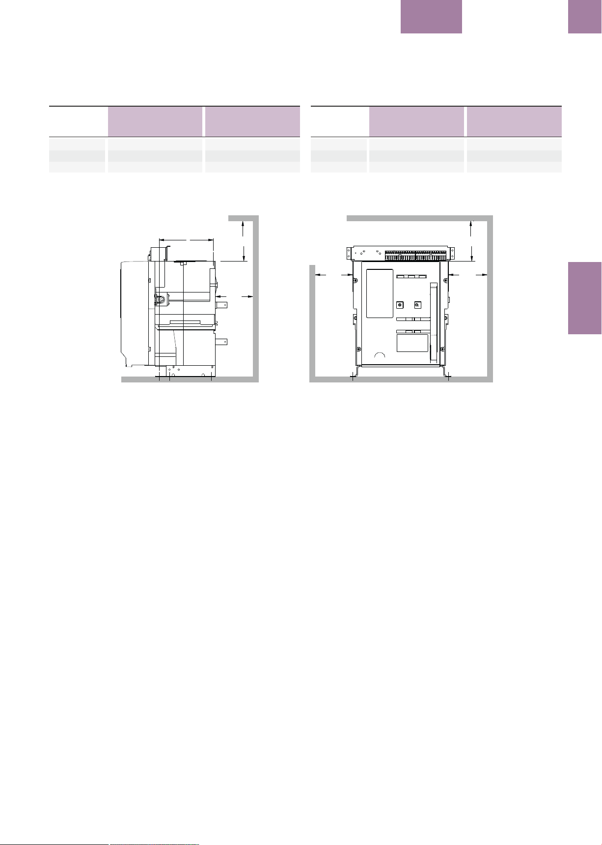
BREAKER
EntelliGuard L
Minimum Clearance distances on Fixed Pattern breaker from housing too:
Espaçamento mínimo no disjuntor de execução fixa, incluindo o invólucro
Minimalne odstępy izolacyjne od obudowy wyłącznika stacjonarnego do:
B1
B2
Metal Parts
Peças metálicas
Elementów metalowych
A
160
30
30
Insulated Parts
Peças isoladas
Elementów izolacyjnych
160
30
30
182 mm min. to
remove Arc Chutes
A
Side view
B1
Minimum Clearance distances from Draw-out cassette housing too:
Espaçamento mínimo no disjuntor de execução extraível, incluindo o chassi
Minimalne odstępy izolacyjne od podstawy wyłącznika wysuwnego do:
Metal Parts
Peças metálicas
Elementów metalowych
(1)
A
B1
B2
(1) With Cassette top covers ; distance without these parts 160mm.
(1) Com cobertura superior do chassi; distância de 160mm sem essas peças.
0
30
30
Insulated Parts
Peças isoladas
Elementów izolacyjnych
0
30
30
Front view 3pole
A
B1 B2
1.3
INSTALLATION
1.3.2 Fixed Circuit Breaker
Installation
1. Ensure adequate clearance above the circuit
breaker to allow removal of the arc chutes and
inspection of the arcing contacts.
2. Mount and position the Circuit breaker on to a
suitable support structure using four M8 bolts.
Torque to 25 Nm.
3. A clearly marked grounding point is provided
on either side of the circuit breaker.
1.3.3 Drawout Circuit Breaker
Installation
Drawout type circuit breakers are normally
delivered already mounted in cassettes.
1. Remove the circuit breaker from its cassette
using withdrawal procedures described in
Section 1.3.3.1.
2. Place the cassette as required in the
switchboard. The cassette can be lifted by hand ;
however, if lifting gear is used, all four lifting
holes provided at front and rear of cassette must
be used.
3. Position cassette in place and connect
incoming and outgoing cables/busbars. Ensure
there is minimal deflection/stress to the back of
the cassette when connecting busbars.
4. Mount the cassette using four M8 bolts and
torque to 25 N m at the front and rear mounting
points.
5. Check the mounting to:
-- Ensure the cassette base is flat and the frame
is square.
-- Ensure the safety shutters move freely after
the mounting bolts have been fully tightened.
1.3.2 Instalação do Disjuntor Fixo
1. Garanta espaço suficiente por cima do
disjuntor de modo a conseguir remover as
câmaras de extinção e inspeção dos contatos
de arco.
2. Usando quatro parafusos M8, montar e
posicionar o disjuntor numa estrutura de
suporte apropriada. Torque de 25 Nm.
3. O disjuntor está provido em ambos os lados
de um ponto de ligação à terra bem assinalado.
1.3.3 Instalação do Disjuntor
Extraível
Os disjuntores do tipo extraível são
normalmente entregues já inseridos no chassi.
1. Remova o disjuntor do seu chassi usando os
procedimentos de extração descritos na Secção
1.3.3.1.
2. Insira o chassi no painel como exigido. O
chassi pode ser erguido manualmente; no
entanto, se for usado equipamentos de
içamento, todos os quatro olhais de içamento
fornecidos na dianteira e traseira do chassi
devem ser usados.
3. Posicione o chassi no lugar e ligue os
cabos/barramentos de entrada e saída.
Assegure o mínimo de deflexão / esforço na
parte traseira do chassi quando ligar as
barramentos.
4. Monte o chassi usando quarto parafusos M8
e torque de 25 Nm nos pontos de montagem
frontais e traseiros.
5. Verifique a montagem para:
-- Assegurar que a base do chassi é plana e que
o aspecto é quadrado.
-- Assegure que os obturadores de segurança
abrem livremente depois de os parafusos de
1.3.2 Instalacja wyłącznika
stacjonarnego
1. Nad wyłącznikiem należy pozostawić
odpowiedni odstęp, aby możliwe było zdjęcie
komór łukowych i sprawdzenie styków opalnych.
2. Ustawić i zamocować wyłącznik w
docelowym położeniu na konstrukcji wsporczej
przy użyciu śrub M8. Moment dociskowy do 25
Nm.
3. Z obydwu stron wyłącznika znajdują się
punkty do podłączenia uziemienia.
1.3.3 Instalacja wyłącznika
wysuwnego
Wyłączniki wysuwne są zwykle dostarczane w
podstawie.
1. Wyjąć wyłącznik z podstawy postępując w
sposób opisany w Rozdziale 1.3.3.1.
2. Zamocować podstawę w rozdzielnicy.
Podstawę można przenosić ręcznie, jednak jeśli
jest przenoszona za pomocą innego urządzenia
- należy użyć wszystkich czterech uchwytów
transportowych z przodu i z tyłu podstawy.
3. Ustawić podstawę w miejscu zamocowania i
podłączyć kable/szyny zasilające i odpływowe.
Dopilnować, aby odkształcenia / naprężenia
tylnej części podstawy przy podłączaniu szyn
były możliwie najmniejsze.
4. Przymocować podstawę śrubami M8 w
otworach mocujących z przodu i z tyłu,
przykręcając je momentem nie przekraczającym
25 Nm.
5. Sprawdzić zamocowanie:
-- sprawdzić czy płyta bazowa podstawy jest
płaska, a rama prostokątna,
-- sprawdzić czy osłony izolacyjne poruszają się
swobodnie po pełnym dokręceniu śrub
mocujących.
1.3-05
Page 24

EntelliGuard L
INTRO BREAKER ACCESSORIES TESTS APPENDIX
LOCKS
TRIP UNIT
DANGER | PERIGO | NIEBEZPIECZEŃSTWO
Please ensure that the breaker is placed in
tripped position, that the operation indicator
shows OFF and that the mechanisms springs
INTRO
are fully discharged.
6. Replace the Device in the cassette as
described in section 1.3.3.2
7. If needed, a clearly marked grounding point is
provided on both sides of the cassette.
1.3.3.1 Circuit Breaker Removal from the
SPECIFICATION
Cassette
Lift the circuit breaker clear of the draw out
support slides using the hand grips on either
side (Fig. 1.3 page 1.3-00) or the lifting eyes (Fig.
1.4).
1.3.3.2 Circuit breaker Mounting in the
Cassette.
1. Take out the racking handle from the storage
INSTALLATION
tube, with a screw driver turn the racking handle
shutter drive Anti-clockwise and insert handle
then rotate the Handle in Anti-clockwise till it
gets a positive stop. Ensure cassette position
indicator shows DISCONNECT and racking
handle is disengaged.
2. Fully extend the cassette draw out support
slides until they reach a positive stop.
OPERATIONTRIP UNIT
3. Switch OFF the breaker by pressing OFF push
button fig. 1.7a
4. Lower the device on to the drawout support
slides making use of the lifting methods
described here. Carefully verify that the pockets
in the Housings of this device are correctly
engaged on the slides.
5. Push the circuit breaker into the cassette
equally on both right and left sides until it
reaches a positive stop. Ensure the position of
rails are equal on Both sides. The circuit breaker
is now in the DISCONNECTED position.
6. Take out the racking handle from the storage
location fig. 1.7b
7. With a screwdriver, turn the racking handle
shutter drive clockwise (Fig. 1.5c), insert the
racking handle and rotate clockwise to rack the
circuit breaker into the cassette. As the breaker
approaches the TEST position check the
alignment of the fixed and moving parts of the
secondary circuit isolating contacts.
8. Keep on rotating the racking handle
clockwise. The racking drive indicator will move
from the DISCONNECTED to TEST and finally to
Por favor assegure-se que o disjuntor é
colocado na posição disparado, que o indicador
de posição indica OFF e que os mecanismos de
mola estão completamente descarregados.
Enquanto elevado, não toque nos contatos de
isolamento do disjuntor.
montagem serem completamente apertados.
6. Insira o aparelho no chassi, como descrito na
seção 1.3.3.2
7. Se necessário, está disponível em ambos os
lados do chassi um ponto de ligação à terra.
1.3.3.1 Remoção do Disjuntor da Chassi
Levante claramente o disjuntor dos suportes
extensíveis de extração, usando as pegas
manuais de cada lado (Fig. 1.3) ou os olhais de
içamento (Fig. 1.4).
1.3.3.2 Montagem do Disjuntor no Chassi.
1. Retire a manivela de extração do tubo de
armazenamento, com uma chave de fenda gire
o obturador da manivela de extração no sentido
anti-horário, insira a manivela e então gire a
manivela no sentido anti-horário até que o
mesmo seja forçado a parar. Confirme que o
indicador de posição do chassi mostra
DESCONECTADO e que a manivela de extração
esteja desengatada.
2. Estenda totalmente os suportes de extração
do chassi, até que eles não saiam mais.
3. Desligue o disjuntor pressionando o botão
OFF fig. 1.7a
4. Desça o dispositivo nos trilhos do suporte
extraível utilizando os métodos de içamento
descritos aqui. Cuidadosamente verifique que
os encaixes deste dispositivo estão
corretamente engatados nos trilhos.
5. Empurre o disjuntor para dentro do chassi
igualmente pela direita e esquerda até que o
mesmo seja forçado a parar. Confirme que a
posição dos trilhos é igual em ambos os lados. O
disjuntor está agora na posição
DESCONECTADO.
6. Retire a manivela de extração do seu local de
armazenamento fig. 1.7b
7. Com uma chave de fenda, gire o obturador da
manivela de extração no sentido horário (fig.
1.5c), insira a manivela de extração e gire no
sentido horário para inserir o disjuntor no chassi.
A medida que o disjuntor se aproxima da
posição TESTE, confirme o alinhamento das
partes fixas e móveis dos contatos de
Wyłącznik powinien być otwarty (przez
wyzwolenie), wskaźnik stanu powinien
wskazywać OFF (WYŁ), sprężyny mechanizmu
napędowego powinny być całkowicie luźne
(rozbrojenie).
6. Wsunąć aparat w podstawę w sposób
opisany w rozdziale 1.3.3.2
7. W razie potrzeby podłączyć uziemienie w
punktach znajdujących się po obu stronach
podstawy.
1.3.3.1 Wyjmowanie wyłącznika z podstawy
Unieść wyłącznik i wyciągnąć z prowadnic
podstawy używając uchwytów po obu stronach
(Fot. 1.3) lub uchwytów transportowych (Fot.
1.4).
1.3.3.2 Wkładanie wyłącznika w podstawę
1. Wyjąć korbę napędu z opakowania, za
pomocą wkrętaka obrócić wkręt przesuwający
przesłonę otworu korby, przeciwnie do kierunkiu
wskazówek zegara, włożyć korbę, potem
obracać przeciwnie do ruchu wskazówek zegara
aż do zatrzymania. Upewnić się, że wskaźnik
położenia w podstawie jest w położeniu
ODŁĄCZONY i korba napędu jest wyjęta.
2. Całkowicie wysunąć prowadnice wsporcze
podstawy, aż do zatrzymania.
3. Wyłączyć wyłącznik przez naciśnięcie
przycisku OFF, fot. 1.7a
4. Osadzić aparat na prowadnicach wsporczych
podstawy użyć urządzeń i metod opisanych w
tej instrukcji. Ostrożnie sprawdzić czy kieszenie
w obudowach aparatu są prawidłowo
osadzone na prowadnicach.
5. Pchać równomiernie prawo/lewo wyłącznik
na prowadnicach w podstawę aż do
zatrzymania. Dopilnować aby pozycja na
szynach była jednakowa z obu ston. Wyłącznik
jest teraz w położeniu ODŁĄCZONY.
6. Wyjąć korbę z mechanizmu wsuwania, fot.
1.7b
7. Używając wkrętaka obrócić wkręt
przesuwający przesłonę otworu korby, zgodnie z
kierunkiem wskazówek zegara (fot . 1.7), włożyć
korbę i obracać zgodnie z kierunkiem
wskazówek zegara, aby wsunąć wyłącznik w
podstawę.
Gdy wyłącznik zbliża się do położenia PRÓBA
sprawdzić wzajemne ustawienie i dopasowanie
części stałej i ruchomej przyłączy obwodów
Fig. 1.5c: Racking Screw Location
A) Racking Screw Shutter Drive
A) Obturador da manivela de extração
A) Lokalizacja śruby napędu wsuwania
A
1.3-06
Fig. 1.5b: Slides
..on which the breaker rollers must engage
..no qual os rolamentos to disjuntor devem engrenar
..na których powinny być osadzone rolki wyłącznika
A
Page 25

BREAKER
EntelliGuard L
1.3
the CONNECTED position. As the cluster of the
mobile parts start engaging with the contacts on
the cassette the force required to turn the
racking handle increases sharply.
CAUTION: If a Motor Spring Charge or
Undervoltage Release is installed, these may
operate when approaching the TEST position.
9. Remove and store the racking handle (Fig.
1.7b).
10. The circuit breaker is now ready for normal
operation.
isolamento do circuito secundário.
8. Continue girando a manivela de extração no
sentido horário. O indicador de manobra
mudará da posição DESCONECTADO para TESTE
e depois para CONECTADO. A medida que os
terminais das partes móveis começam a se
conectar com os contatos no chassi, a força
necessária para girar a manivela aumenta
considerávelmente.
CUIDADO: Se o motor de carregamento da
mola ou uma bobina de mínima tensão estão
instalados, podem operar imediatamente
quando o disjuntor se aproxima da posição
TESTE.
9. Remova e guarde a manivela de extração
(1.7b).
10. O disjuntor está pronto para operação
normal.
pomocniczych.
8. Kontynuować obracanie korby zgodnie ze
wskazówkami zegara.
Wskaźnik położenia przesunie się z położenia
ODŁĄCZONY do położenia PRÓBA, następnie do
pozycji PRACA.
Gdy zaciski szczękowe torów głównych części
ruchomej wyłącznika rozpoczną zakleszczanie
na zaciskach podstawy - siła konieczna do
obracania korby znacznie wzrośnie.
UWAGA: Jeśli w wyłączniku jest zainstalowany
napęd silnikowy lub wyzwalacz podnapięciowy,
można je sprawdzić gdy wyłącznik jest w
położeniu / (zbliża się do położenia) PRÓBA.
9. Wyjąć korbę i włożyć do schowka (1.7b).
10. Wyłącznik jest gotowy do pracy.
INSTALLATION
Fig. 1.7a
Fot.
A
Fig. 1.7b
Fig. 1.7c
Fot.
A
Fot.
Fig. 1.7d
Fot.
Fig. 1.7e
Fot.
Fig. 1.7f
Fot.
1.3-07
Page 26
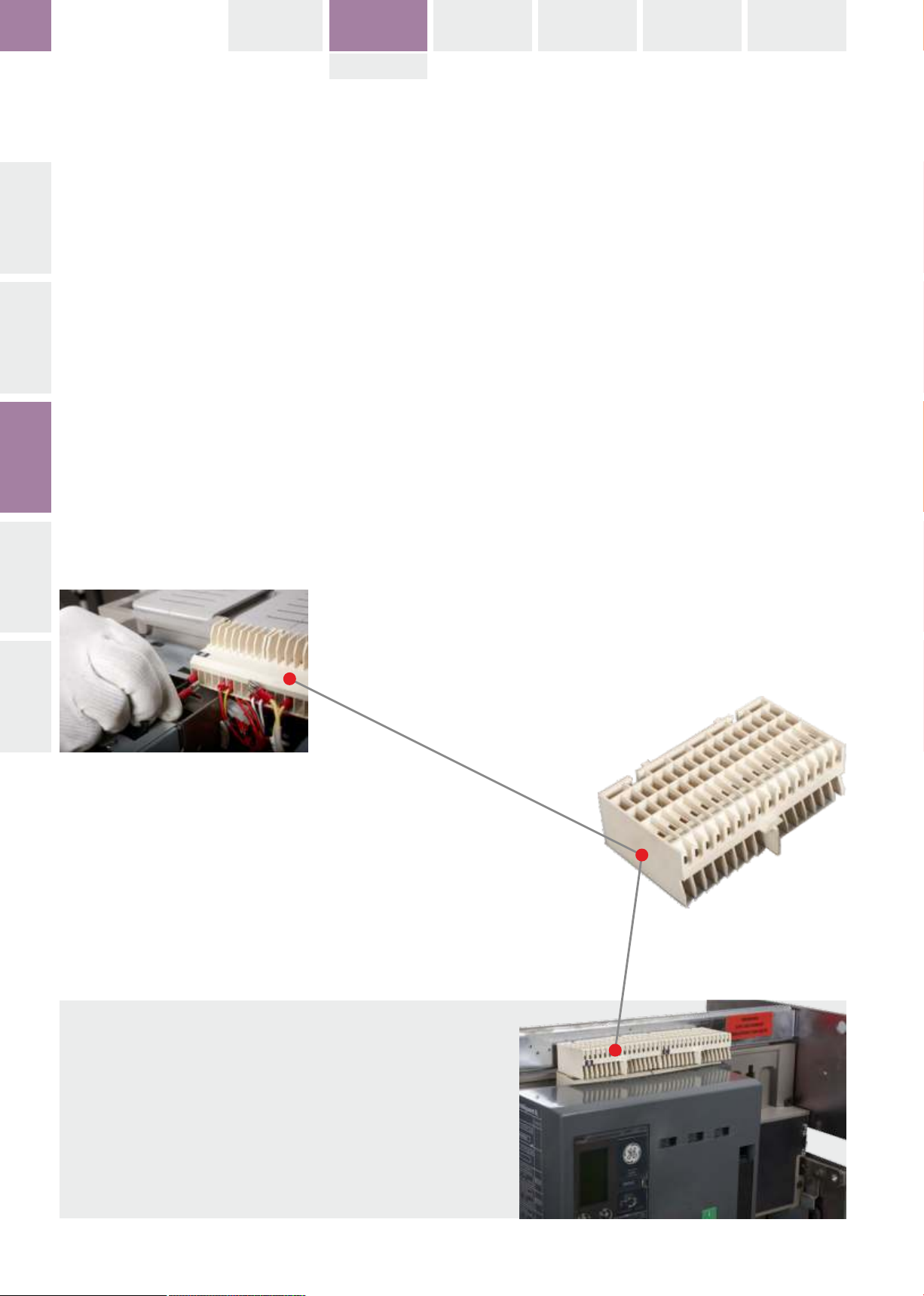
EntelliGuard L
INTRO BREAKER ACCESSORIES TESTS APPENDIX
LOCKS
TRIP UNIT
1.3.4 SECONDARY DISCONNECT
TERMINAL BLOCKS
Breakers in Fixed Pattern, cassettes and
breakers in draw out mode are always supplied
INTRO
with an auxiliary connection block with 32
connection points (terminals) . These are easily
accessible and located at the top and front of
the device.
-- The terminals can be used up to a rating of 5A
at 415V AC or 0,25A at 250V DC. They can be
used with unprepared stripped conductors or
pin type wires.
SPECIFICATION
Schematics and use of terminals see next page.
INSTALLATION
OPERATIONTRIP UNIT
1.3.4 BLOCOS TERMINAIS
SECUNDÁRIOS
Os disjuntores do tipo fixo, chassis e disjuntores
extraíveis são sempre fornecidos com terminais
auxiliares numa régua de terminais com 32
pontos. Estes são facilmente acessíveis e estão
localizados no topo frontal do aparelho.
-- Os terminais podem ser usados até uma
corrente de 5 A em 415 Vca ou 0,25 A em 250
Vcc. Eles podem ser utilizados com condutores
desencapados ou cabos tipo pino.
Para esquemas e uso dos terminais, ver próxima
página.
1.3.4 LISTWY PRZYŁĄCZENIOWE
OBWODÓW POMOCNICZYCH
Wyłączniki w wersji stacjonarnej, podstawy i
wyłączniki wysuwne są zawsze dostarczane z
listwą przyłączeniową dla obwodów
pomocniczych, zawierającą 32 punktów
podłączeniowych (zacisków). Są one łatwo
dostępne w górnej przedniej części aparatu.
-- Obciążalność zacisków wynosi 5A przy 415V
AC lub 0,25A przy 250V DC. Zaciski mogą być
używane do podłączenia nieobrobionych
przewodów z usuniętą izolacją, są
przystosowane do podłączenia przewodów z
końcówkami widełkowymi płaskimi lub
pierścieniowymi.
Schematy i przeznaczenie zacisków są
przedstawione na następnej stronie.
SYGNALIZACJA
LP1: Stan zazbrojenia sprężyn
LP2: Wyłącznik otwarty
LP3: Wyłącznik zamknięty
LP4: Zwarcie / przeciążenie
LP5: Wyłącznik gotowy do zamknięcia
CC: Cewka zamykająca
ST: Wyzwalacz napięciowy
UVR: Wyzwalacz podnapięciowy
SCC: Styk sygnalizacji naciągnięcia sprężyn
(zazbrojenie)
RTC: Styk gotowości do zamknięcia
M: Napęd silnikowy
BAT: Łącznik alarmowy wyzwolenia
INDICATION
LPI SPRING CHARGE STATUS
LP2 BREAKER OPEN
LP3 BREAKER CLOSED
LP4 FAULT
LP5 BREAKER READY TO CLOSE
CC CLOSE COIL
ST SHUNT RELEASE
UVR UNDER VOLTAGE RELEASE
SCC SPRING CHARGE CONTACT
RTC READY TO CLOSE CONTACT
M MOTOR OPERATOR
BAT BELL ALARM TRIP
1.3-08
Indicação
LP1 Estado de carregamento da mola
LP2 Disjuntor aberto
LP3 Disjuntor fechado
LP4 Falta
LP5 Disjuntor pronto para fechar
CC Bobina de fechamento
ST Bobina de abertura
UVR Bobina de mínima tensão
SCC Contato de carregamento da mola
RTC Contato pronto para fechar
M Motorização
BAT Disparo do contato de alarme
Page 27
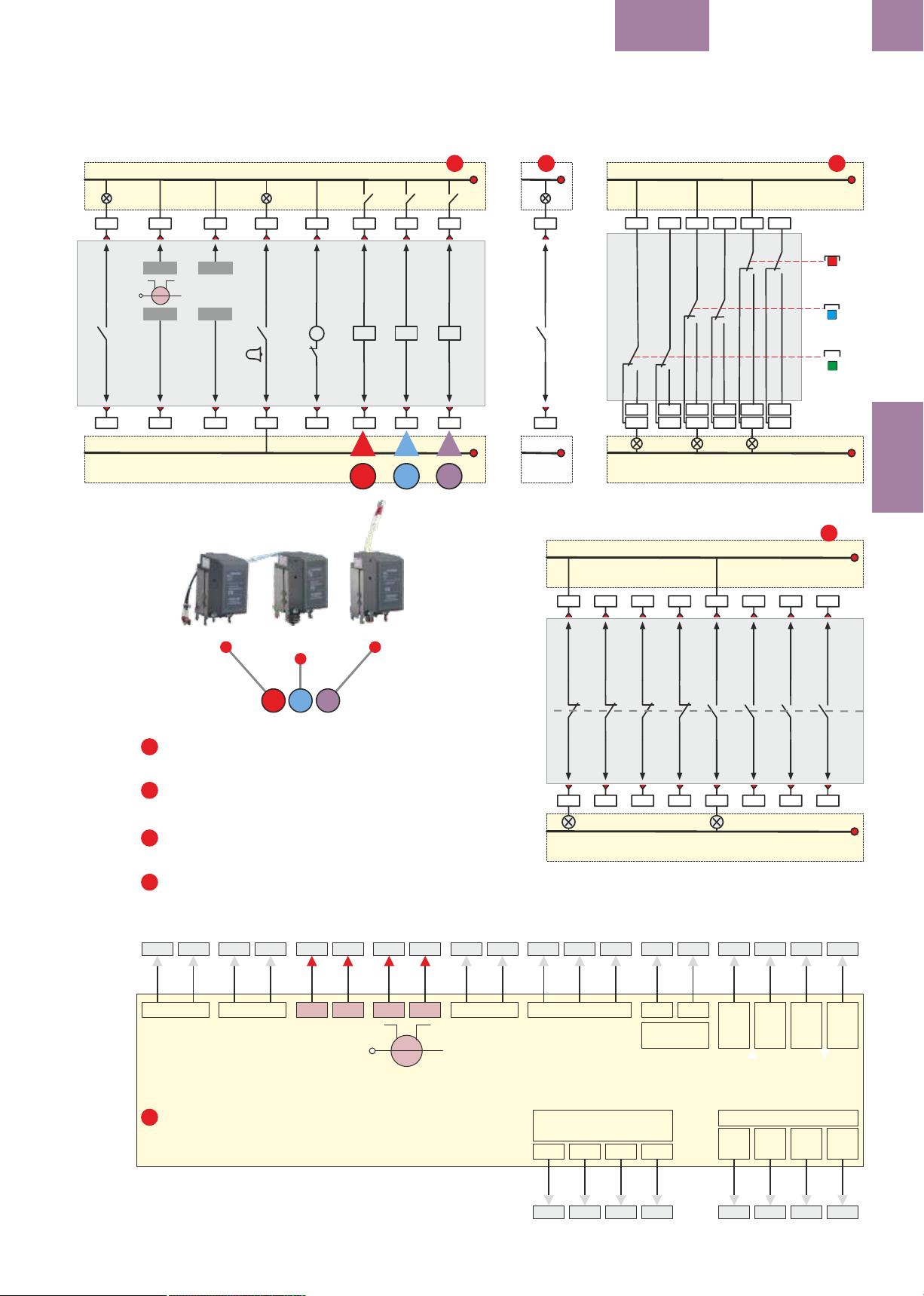
User‘s designated circuits | Circuitos atribuídos ao utilizador | Obwody uzytkownika
BREAKER
EntelliGuard L
1.3
1
2
3
LP1
B1
SPR
57
58
B2
A: Wyzwalacz napięciowy (wzrostowy)
B: Wyzwalacz podnapięciowy (zanikowy)
C: Cewka zamykająca
B3
N-RC +
-
N
N-RC -
B4
B5
24V +
+
+24VDC
24V -
B6
Shunt Release
B7
T
BAT
B8
LP4
B9
M1
98
M
95
M2
B10
Undervoltage
Release
ML
B11
C1
C2
UVR
ST
B12
A
Closing Coil
LP5
D4
B13
B15
B1
D1
RTC
C3
D1
C4
D2
CC
B14
B16
B
C
57
58
B2
11
12
22
14
D3
D2
LP6
D7 D10 D13 D16
31
42
32
34
21
24
D6
D9 D12 D15 D18
D5
D8 D11 D14 D17
LP7
CONNECTED
51
61
52
62
54
64
41
44
LP8
CONECTADO
Praca
TESTE
Próba
DISCONNECTED
DESCONECTADO
Odłączenie
TEST
INSTALLATION
C13
4
C15
User‘s designated circuits | Circuitos atribuídos ao utilizador | Obwody uzytkownika
C1
C3
C5
C9
C7
C11
B
A
STANDARD CONNECTION SCHEME FOR TERMINAL BLOCK B
1
ESQUEMA DE LIGAÇÃO PADRÃO PARA O BLOCO DE TERMINAIS B
Schemat połączeń standardowych dla listy zaciskowej B
Optional connection scheme for RTC (Block B)
2
Esquema de conexão opcional para o RTC (Bloco B)
Schemat połączeń opcjonalnych dla RTC (blok B)
CONNECTION SCHEME FOR Cassette Position Indication Contacts
3
ESQUEMA DE LIGAÇÃO Para contatos de indicação de posição no chassi
Schemat podłączenia styków sygnalizacji położenia w podstawie
STANDARD CONNECTION SCHEME FOR TERMINAL BLOCK C
4
ESQUEMA DE LIGAÇÃO PADRÃO PARA O BLOCO DE TERMINAIS C
Schemat połączeń standardowych dla listy zaciskowej C
C
B3 B4B5 B6
- - -N-RC N-RC
Electronic Trip Unit
5
Unidada de disparo eletrônica
Elektroniczny wyzwalacz nadprądowy
24V+ 24V- -
-
+24VDC
N
GT-L
11
21
31
12
22
32
C2
C4
C6
C8
LP2
*) ..when 3 sets of auxiliary contact are installed, contacts 41, 42 43 and 44 are not present.
*) ..gdy zainstalowane są 3 zestawy styków pomocniczych, styki 41, 42, 43 i 44 nie są obecne.
+
*) ..quando 3 conjuntos de contatos auxiliaries estão instalados,
- -
13
41
42
C10
os contatos 41, 42, 43 e 44 não estão presentes.
23
33
43
14
24
34
44
C12
C14
C16
LP3
- - - -
-
Connection scheme | | Schemat połączeń Esquema de Ligação
-
-
-
-
-
-
-
- -
-
1.3-09
Page 28
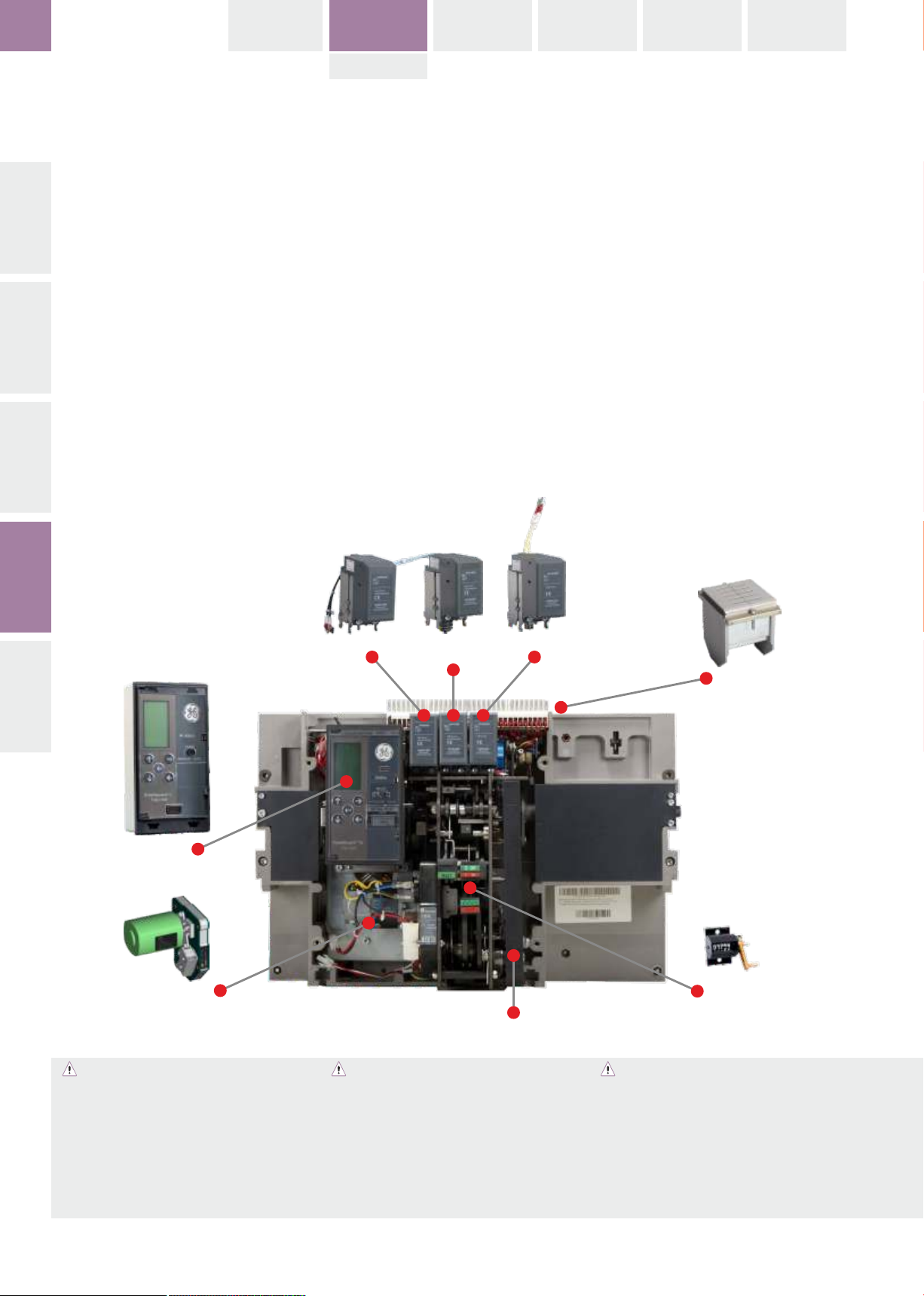
EntelliGuard L
INTRO BREAKER ACCESSORIES TESTS APPENDIX
LOCKS
TRIP UNIT
Content
INTRO
--------------------------------------------------------
1.4 OPERATION
--------------------------------------------------------
1.4.1 Charging of Main Springs
Manually
Electrically
1.4.2 Sequence of operation
1.4.3 Circuit breaker closing operation
SPECIFICATION
1.4.4 Circuit breaker opening operation
1.4.5 Circuit breaker Withdrawal
1.4.6 Circuit breaker Insertion
1.4.7 Sequence of operation cassette
INSTALLATION
Conteúdo
---------------------------------------------------------
1.4 OPERAÇÃO
---------------------------------------------------------
1.4.1 Carregamento das molas principais
Manualmente
Eletricamente
1.4.2 Sequência de operações
1.4.3 Operação de fechamento do disjuntor
1.4.4 Operação de abertura do Disjuntor
1.4.5 Extração do Disjuntor
1.4.6 Inserção do Disjuntor
1.4.7 Sequência de operação no chassi
Spis treści
---------------------------------------------------------
1.4 OBSŁUGA
---------------------------------------------------------
1.4.1 Naciąganie sprężyn głównych (zbrojenie)
Ręczne
Elektryczne
1.4.2 Kolejność operacji
1.4.3 Zamykanie wyłącznika
1.4.4 Otwieranie wyłącznika
1.4.5 Wysuwanie wyłącznika
1.4.6 Wsuwanie wyłącznika
1.4.7 Położenia wyłącznika wysuwnego
względem podstawy
OPERATIONTRIP UNIT
Trip Unit
Motor operator
Undervoltage
Release
Closing CoilSHUNT Release
Arc chute
Operation
Counter
Spring charging handle
WARNING:
Only qualified personnel are allowed to install,
operate and maintain all electrical equipment.
Caution:
Whilst handling the breaker avoid injury due to
moving parts.
1.4-00
AVISO:
Somente pessoas qualificadas podem instalar,
operar e manter todos os equipamentos
elétricos.
Atenção:
Ao manusear o disjuntor evite ferimentos devido
às partes móveis.
OSTRZEŻENIE:
Instalacja, obsługa, i konserwacja urządzeń
elektrycznych może być wykonywana tylko
przez wykwalifikowanych specjalistów.
Uwaga:
Przy przenoszeniu wyłącznika uważać na
ruchome elementy mogą spowodować
obrażenia.
Page 29

BREAKER
EntelliGuard L
1.4
1.4 OPERATION
CAUTION: Ensure circuit breaker and its
accessories are always used within their
designated ratings.
Use the specially designed circuit breaker
handling truck (optional accessory) when
removing the circuit breaker from its cassette.
1.4.1 Charging of main springs
1.4 OPERAÇÃO
ATENÇÃO: Certifique-se de disjuntor e seus
acessórios são sempre utilizados conforme as
suas funções e calibres atribuídos.
Use o carro de extração do disjuntor
especialmente projetado (acessório opcional)
quando remover o disjuntor do seu chassi.
1.4.1 Carregamento a das molas
principais
NOTICE: 1 charging cycle provides sufficient
energy for an O-C-O (Open-Close-Open)
operation.
The mechanism only operates correctly when
the device is mounted on a horizontal plane and
fixed at the bottom.
Device Charging (manual)
– Extend handle (Fig.1.4.3)
-- Rotate or depress handle in a downwards
direction.
-- Allow the handle to return to it's original
position. A clearly audible click indicates that the
operation is completed.
– Repeat the above mentioned process 10 times,
thus fully charging the springs. The status
indicator will now be RED: The mechanism
design includes measures that prevent over
extension and operator injury.
Device Charging (electrical)
The optionally available spring charging
mechanism (motor) will automatically charge
the springs directly after a closing operation.
This takes maximum 5 seconds.
1.4.2 Sequence of operation
Table 1.20: Stored Energy Mechanism Sequences of Operation
ON/OFF Main Breaker Charging Spring Condition of Charging Next Permissible Operating Function
Indicator Contacts Indicator Springs
OFF open discharged discharged closing springs may be charged
OFF open charged fully charged contacts may be closed
ON closed discharged discharged contacts may be opened or closing springs may be charged
ON closed charged fully charged contacts may be opened
ON closed charging partially charged complete charging
OFF open charging partially charged complete charging
Tabela 1.20: Sequências de operação do mecanismo de armazenamento de energia
ON/OFF Disj. Principal Indicador de carregamento Condição da carga Próxima função de operação permitida
Indicador Contatos da mola das molas
OFF aberto descarregado descarregado podem ser carregadas as molas de fecho
OFF aberto carregado completamente carregado podem ser fechados os contatos
ON fechado descarregado descarregado podem ser abertos os contatos ou as molas de fecho
podem carregadas
ON fechado carregado completamente carregado podem ser abertos os contatos
ON fechado carregando carregado parcialmente carga completa
OFF aberto carregando carregado parcialmente carga completa
Tabela 1.20: Kolejność operacji i stany głównych elementów mechanizmu wyłącznika w cyklu łączeniowym
Wskaźnik Styki główne Wskaźnik Stan naciągnięcia Następna możliwa operacja
ZAŁ./WYŁ. wył-ka zazbrojenia sprężyn
WYŁ. otwarte rozbrojony luźne można naciągnąć sprężyny zamykające
WYŁ. otwarte zazbrojony całkowicie naciągnięte można zamknąć styki
ON zamknięte rozbrojony luźne można otworzyć styki lub naciągnąć sprężyny
ON zamknięte zazbrojony całkowicie naciągnięte można otworzyć styki
ON zamknięte zbrojenie częściowo naciągnięte pełne zazbrojenie
WYŁ. otwarte zbrojenie częściowo naciągnięte pełne zazbrojenie
AVISO: 1 ciclo de carga fornece energia
suficiente para uma operação A-F-A (Abrir –
Fechar - Abrir).
O mecanismo somente opera corretamente
quando o dispositivo está montado num plano
horizontal e fixo no fundo.
Carregando o mecanismo (manual)
-- Estenda a manivela (Fig.1.4.3)
-- Rodar ou puxar a manivela para baixo.
-- Permitir que a manivela regresse à sua
posição original. Um clique claramente audível
indica que a operação está concluída.
-- Repita o processo acima mencionado 10
vezes, assim está completo o carregamento das
molas. O indicador de estado estará agora
VERMELHO: O projeto do mecanismo inclui
medidas que previnem e limitam danos ao
utilizador.
Carregando o mecanismo (elétrico)
O mecanismo de carregamento de mola (motor)
disponível, carregará as molas
automaticamente logo após uma operação de
fecho. Esta operação leva no máximo 5
segundos.
1.4.2 Sequence de operação
1.4 OBSŁUGA
UWAGA: Wyłącznik i jego wyposażenie należy
używać w zakresie ich parametrów
znamionowych.
Przy wyjmowaniu wyłącznika z podstawy
używać specjalnego podnośnika (wyposażenie
opcjonalne).
1.4.1 Zbrojenie napędu (naciąganie
sprężyn głównych)
UWAGA: 1 pełne zazbrojenie (naciągnięcie
sprężyn) zapewnia ilość energii wystarczającą
do wykonania cyklu łączeniowego O-Z-O
(Otwórz-Zamknij-Otwórz).
Mechanizm napędowy funkcjonuje prawidłowo,
jeśli aparat jest ustawiony na płaszczyźnie
poziomej i zamocowany do niej spodem.
Ręczne zbrojenie napędu
-- Wyciągnąć dźwignię (Fot.1.4.3)
-- Nacisnąć dźwignię ku dołowi.
-- Zwolnić dźwignię aby mogła powrócić do
położenia początkowego. Łatwo słyszalny
odgłos (klik) oznacza zakończenie operacji.
-- Powtórzyć operację opisaną powyżej 10 razy,
po czym sprężyny zostaną naciągnięte.
Wskaźnik stanu zmienia kolor na CZERWONY.
Mechanizm napędowy posiada zabezpieczenia
zapobiegające nadmiernemu naciągnięciu
sprężyny i narażeniu operatora na obrażenia.
Elektryczne zbrojenie napędu
Napęd elektryczny (silnik) dostępny opcjonalnie
naciąga aprężyny automatycznie bezpośrednio
po zamknięciu wyłącznika.
Zajmuje to maksymalnie 5 sekund.
1.4.2 Kolejność działań
OPERATION
1.4-01
Page 30

EntelliGuard L
INTRO BREAKER ACCESSORIES TESTS APPENDIX
LOCKS
TRIP UNIT
1.4.3 CIRCUIT BREAKER
CLOSING OPERATION
1. The circuit breaker can be closed, if:
- The OFF button is not depressed.
INTRO
- The Trip Unit is installed.
- No pending ON command is present
- The network interlock if installed is reset.
- If installed, the Undervoltage release (s) are
energized.
- No local keylocks or in- or external breaker
interlocks are set to PREVENT the user from
switching ON.
- The cassette racking handle is not inserted.
- The Trip Unit reset button is not protruding
SPECIFICATION
from the front cover.
- The circuit breaker is not positioned anywhere
between CONNECTED, TEST and DISCONNECTED.
–
If any of the above conditions are NOT met the
device is prevented from closing.
INSTALLATION
–
2. Closing the Device
Depressing the 'ON' pushbutton located on the
breaker front fascia. (Fig.1.7) will close the
Breaker.
1.4.3 OPERAÇÃO DE FECHAMENTO
DO DISJUNTOR
1. O Disjuntor pode ser fechado, se:
- O botão OFF não está pressionado.
- A Unidade de disparo está instalada.
- Não há comando ON pendente presente
- O intertravamento de rede, caso instalado,
esteja em reset.
- Caso instalada, a(s) bobina(s) de mínima esteja
energizada.
- Não há intertravamentos ou bloqueios de
disjuntores externos ajustados para IMPEDIR
que o usuário o ative.
- A manivela de extração não está inserida.
- O botão de restabelecimento da Unidade de
Disparo não está saliente da cobertura frontal.
- O disjuntor não está posicionado em qualquer
sitio entre as posições CONECTADO, TESTE e
DESCONECTADO.
-Se qualquer uma das condições acima NÃO se
verifica, o disjuntor está impedido de fechar.
--
2. Fechando o aparelho
Pressionando o botão "ON" localizado na face
frontal do disjuntor. (Fig. 1.7) irá fechar o
disjuntor.
1.4.3 ZAMYKANIE WYŁĄCZNIKA
1. Wyłącznik można zamknąć, gdy:
- Przycisk OFF (WYŁ.) nie jest wciśnięty
- Wyzwalacz nadprądowy jest zainstalowany
- Nie występuje bieżące polecenie ON (ZAŁ.)
- Blokada sieciowa (jeśli zastosowana) jest
odblokowana
- Wyzwalacz(e) podnapięciowy(e) (jeśli
zainstalowane) są pod napięciem
- Żadna z blokad zamykanych kluczem, blokad
wewnętrznych lub zewnętrznych nie
UNIEMOŻLIWIA użytkownikowi zamknięcia.
- Korba nie jest włożona w mechanizm
wsuwania
- Przycisk odblokowania wyzwalacza
nadprądowego (reset) na płycie czołowej nie jest
wysunięty
- Wyłącznik wysuwny nie znajduje się między
położeniami PRACA, PRÓBA, ODŁĄCZONY.
--Jeśli którykolwiek z powyższych warunków NIE
jest spełniony zamknięcie aparatu nie jest
możliwe.
---
2. Zamknięcie wyłącznika
Wciśniecie przycisku 'ON' (ZAŁ.) na płycie
czołowej wyłącznika. (fot.1.7) zamyka wyłącznik.
OPERATIONTRIP UNIT
NOTICE: If a motorized Spring Charging Unit is
installed, the springs will be automatically
charged as soon as the closing operation is
initialized.
1.4.4 Circuit Breaker
Opening Operation
NOTICE: If the device is a breaker it will always
AUTOMATICALLY Trip on closing or being
exposed to faults that exceed the values set or
installed on the installed protective devices.
(GT type Electronic Trip Unit).
There are multiple means to open the breaker.
Manually
Using the off Pushbutton will open the breaker.
Standard Shunt Release or Remote Reset Coil
1 Shunt release can be installed to open the
breaker. For this the shunt releases must be
energized via the secondary disconnect
(terminals).
Undervoltage release
1 undervoltage release can be installed and will
open the breaker
once their power
supply drops below
a certain level.
Standard
Undervoltage
releases have a
built in time delay
of up to 50 ms
whilst, on request
some variants are
available without
delay.
AVISO: Caso o mecanismo de carregamento
motorizado esteja instalado, as molas serão
automaticamente carregadas assim que
começar a operação de fechamento.
1.4.4 Operação de Abertura do
Disjuntor
AVISO: Se o aparelho é um disjuntor, este
disparará sempre AUTOMATICAMENTE ao ser
exposto a faltas que excedem os valores
estabelecidos ou programados na Unidade de
Proteção instalada.
Há várias formas de abrir o disjuntor.
Manualmente
Pressionar o botão OFF irá abrir o disjuntor.
Bobina de disparo padrão
ou bobina de reset remoto
1 Bobinas de disparo podem ser instaladas para
abrir o disjuntor. Para isto as bobinas de disparo
devem ser alimentadas pelos blocos
secundários (terminais).
Bobina de mínima tensão
1 Bobinas de mínima tensão podem ser
instaladas e vão abrir o
disjuntor assim que a sua
tensão de alimentação
cair abaixo de um certo
nível.
Standardowy wyzwalacz
podnapięciowy ma
wbudowaną zwłokę
czasową do 50 milisekund,
wyzwalacze bezzwłoczne
są dostępne na
zamówienie.
UWAGA: Jeśli zastosowany jest napęd
silnikowy sprężyny są naciągane automatycznie
tuż po rozpoczęciu zamykania wyłącznika.
1.4.4 Otwieranie wyłącznika
UWAGA: Jeśli dany aparat jest wyłącznikiem
jest on zawsze otwierany AUTOMATYCZNIE przez
wyzwalacz gdy w obwodzie występuje lub
wystąpi przeciążenie lub zwarcie przekraczające
wartości progowe ustawione w elektronicznym
wyzwalaczu nadprądowym GT.
Wyłącznik można otworzyć klikoma metodami:
Ręcznie
Wciśniecie przycisku OFF (WYŁ.) powoduje
otwarcie wyłącznika.
Standardowy wyzwalacz napięciowy lub cewka
wybijakowa
W wyłączniku można zastosować 1 wyzwalacz
napięciowy do otwierania wyłącznika.
Otwarcie aparatu następuje po doprowadzeniu
napięcia do wyzwalacza, poprzez listwę
zaciskowa.
Wyzwalacz podnapięciowy
W wyłączniku można zastosować 1 wyzwalacz
podnapięciowy otwierający wyłącznik, gdy
doprowadzone do niego napięcie obniży się
poniżej określonego poziomu.
Standardowy wyzwalacz podnapięciowy ma
wbudowaną zwłokę czasową do 50 milisekund,
wyzwalacze bezzwłoczne są dostępne na
zamówienie.
1.4-02
Fig. 1.4.3
Fot. 1.4.3
Page 31

BREAKER
EntelliGuard L
1.4
1.4.5 Circuit Breaker Withdrawal
Preparation
- Motor operator
If a motorized spring charging unit is installed
rack the breaker to the disconnect position, then
close and trip the breaker to discharge the
closing springs.
Otherwise the motor will recharge the springs
automatically.
— Remove any padlocks from the racking panel.
— Ensure the cabinet/panel door is closed.
Operation:
1. Remove the racking handle from its storage
location (Fig. 1.7b).
2. Pull out the torque bar from inside the handle
and extend the grip arm (Fig. 1.7).
3. Turn the EntelliGuard device OFF. A safety
device ensures that the racking aperture shutter
cannot be opened whilst the device is NOT in it's
DANGER | PERIGO | NIEBEZPIECZEŃSTWO
Ensure the circuit breaker has been tripped,
indicating OFF, and the main springs are fully
discharged.
1.4.5 Extração do Disjuntor
Preparação
- Mecanismo motorizado
Se o mecanismo de carregamento motorizado
está instalado, coloque o disjuntor na posição
desconectado, depois feche e dispare o disjuntor
para descarregar as molas.
De outra maneira o motor vai carregar as molas
automaticamente.
-- Remova quaisquer bloqueios do painel de
extração do chassi.
-- Assegure-se que a porta do painel/armário
está fechada.
Operação:
1. Remova a manivela de extração do seu
compartimento (Fig. 1.7b).
2. Puxe a barra do interior da manivela e
estenda o braço desta. (Fig. 1.7).
3. Abra o aparelho EntelliGuard para a posição
OFF. Um dispositivo de segurança garante que a
abertura para a manivela não se pode abrir até
Assegure-se que o disjuntor foi disparado, indica
OFF, e as molas principais estão completamente
descarregadas.
1.4.5 Wysunięcie wyłącznika
Przygotowanie
- Napęd silnikowy
Jeśli zastosowany jest napęd silnikowy należy
wysunąć wyłącznik do pozycji odłączenia,
następnie zamknąć i wyzwolić (otworzyć)
wyłącznik, aby rozluźnić sprężyny zamykające.
W przeciwnym wypadku silnik będzie
automatycznie naciągać sprężyny.
--- Usunąć wszystkie kłódki z panela napędu
wsuwania.
--- Dopilnować, aby drzwi rozdzielnicy / szafy
były zamknięte.
Wykonanie operacji:
1. Wyjąć korbę ze schowka (Fot. 1.7b).
2. Wyciągnąć drążek skrętny z rączki i rozłożyć
korbę (Fot. 1.7).
3. Otworzyć aparat EntelliGuard (pozycja OFF).
Mechanizm bezpieczeństwa uniemożliwia
otwarcie przesłony otworu korby gdy aparat NIE
jest w pozycji OFF.
Należy sprawdzić czy wyłącznik został
wyzwolony (otwarty), wskazuje pozycję OFF
(WYŁ.), a główne sprężyny są całkowicie luźne.
OPERATION
OFF position.
4. Open the racking aperture shutter fully using
a flat screwdriver (see Fig. 1.7d).
5. Insert the racking handle and rotate it in a
counter clockwise direction. This will cause the
position indicator and device to move from the
CONNECTED to the TEST and DISCONNECTED
position.
NOTICE: When the racking handle is inserted
in the racking shaft, the circuit breaker cannot
be operated in any position between
CONNECTED and DISCONNECTED.
Removing the handle automatically resets the
racking handle shutter.
6. From the DISCONNECTED position, continue
turning the racking handle anti-clockwise until
reaching a positive stop.
NOTICE: Ensure that the closing springs are
fully discharged (spring charge indicator should
show 'Discharged') before attempting to
withdraw from the DISCONNECTED position.
7. The circuit breaker is now in the maintenance
position (Fig. 1.6).
In this position the cabinet/panel door can be
opened and means for lifting can be attached to
the lifting hooks which can be pulled out from
the left and right top of the breaker
..see Table 1.21
que o aparelho NÃO tenha sido colocado na
posição OFF (Aberto).
4. Abra por completo a abertura de inserção da
manivela usando uma chave de fendas plana
(ver Fig. 1.7d).
5. Insira a manivela de extração e gire-a no
sentido anti-horário. Desta forma o indicador de
posição e o dispositivo mudarão da posição
CONECTADO à de TESTE e então à
DESCONECTADO.
AVISO: Quando a manivela de extração está
inserida para operação, o disjuntor não pode ser
operado em nenhuma posição entre
CONECTADO e DESCONECTADO.
Removendo a manivela automaticamente é
reposto o obturador da janela de operação.
6. A partir da posição DESCONECTADO, continue
a rodar a manivela de extração no sentido antihorário até que atinja o final.
AVISO: Assegure-se que as molas de
fechamento estão completamente
descarregadas (o indicador de carga das molas
deve mostrar 'Discharged') antes de extrair da
posição DESCONECTADO.
7. O disjuntor está agora na posição de
manutenção (Fig. 1.6).
Nesta posição a porta do armário / painel pode
ser aberta e podem ser usados meios para
içamento usando os ganchos de elevação que
podem ser puxados para fora , localizados a
esquerda e direita no topo do disjuntor.
..ver Tabela 1.21
4. Otworzyć całkowicie przesłonę otworu korby
używając wkrętaka płaskiego (Fot. 1.7d).
5. Włożyć korbę i obracać w kierunku
przeciwnym do ruchu wskazówek zegara.
Spowoduje to przesunięcie wskaźnika położenia
z pozycji PRACA, a następnie do położeń PRÓBA i
ODŁĄCZONY.
UWAGA: Jeśli korba jest wsunięta do wałka
przesuwu nie można wykonywać operacji
łączeniowych gdy wyłącznik znajduje się w
jakimkolwiek położeniu między PRACA i
ODŁĄCZONY.
Wyjęcie korby automatycznie odblokowuje
przesłonę otworu korby.
6. Od położenia ODŁĄCZONY kontynuować
obracanie korby przeciwnie do wskazówek
zegara, aż do zatrzymania.
UWAGA: Przed wysuwaniem z położenia
ODŁĄCZONY dopilnować, aby sprężyny
zamykające były całkowicie rozluźnione
(wskaźnik zazbrojenia powinien wskazywać
"Rozbrojony" ("Discharged")).
7. Wyłącznik jest teraz w położeniu
konserwacyjnym (Fot.1.6).
Przy tym położeniu aparatu można otworzyć
drzwi rozdzielnicy / szafy i użyć podnośnika,
chwytając za uchwyty transportowe wyciągane
z górnej części wyłącznika po lewej i prawej
stronie.
1.4-03
Page 32

EntelliGuard L
INTRO BREAKER ACCESSORIES TESTS APPENDIX
LOCKS
TRIP UNIT
1.4.6 Circuit breaker insertion
Preparation:
–- Remove all other padlocks from the cassette.
-- Deactivate any cassette keylocks.
INTRO
1. Carefully place the breaker on the fully
extended drawout support slides and Carefully
verify that the pockets in the Housings of this
device are correctly engaged on the slides.
2. Remove any still attached lifting means from
the device.
3. Push the breaker into the cassette by
SPECIFICATION
applying pressure equally to the front fascia (left
and right top area) until the motion comes to
and end.
4. Close the cabinet/panel door.
5. Prepare the cassette and racking handle as
mentioned above (point 1 through 4) and insert
the handle into it's aperture.
6. Rotating the racking handle clockwise moves
INSTALLATION
the breaker in. It can be moved from the
disconnect position to the test position and
further to the connected position, as indicated
by the position indicator (Fig. 1.7).
7. Remove the racking handle and replace it into
its storage location (Fig. 1.7).
Now the breaker is ready to operate.
OPERATIONTRIP UNIT
1.4.6 Inserção do Disjuntor
Preparação:
-- Remova os outros bloqueios por cadeado do
chassi.
-- Desactive quaisquer bloqueios por chave do
chassi.
1. Cuidadosamente coloque o disjuntor nos
trilhos totalmente estendidos do suporte
extraível e cuidadosamente verifique que os
encaixes deste dispositivo estão corretamente
engatados nos trilhos.
2. Remova quaisquer meios de içamento que
esteja acoplado ao aparelho.
3. Empurre o disjuntor para dentro do chassi
aplicando pressão na face frontal (igualmente
para área superior esquerda e direita) até que o
movimento chegue a um fim.
4. Feche a porta do armário / painel.
5. Prepare o chassi e a manivela de extração
como mencionado acima (ponto 1 até 4) e insira
a manivela na sua abertura.
6. Rodando a manivela de extração no sentido
horário, o disjuntor entra no chassi. Este pode
ser movido da posição desconectado para a
posição de teste e depois para a posição de
conectado, como indicado pelo indicador de
posição (Fig. 1.7).
7. Remova a manivela de extração e coloque-a
no seu local apropriado (Fig. 1.7).
Agora o disjuntor está preparado para operar.
1.4.6 Wsunięcie wyłącznika
Przygotowanie:
-- Otworzyć wszystkie blokady w podstawie,
zamykane kłódkami.
-- Otworzyć wszystkie blokady w podstawie,
zamykane kluczami.
1. Ostrożnie ustawić wyłącznik na całkowice
wysuniętych prowadnicach wsporczych
podstawy i uważnie sprawdzić czy kieszenie w
obudowach aparatu są prawidłowo osadzone
na prowadnicach.
2. Usunąć wszelkie elementy użyte do
podnoszenia wyłącznika
3. Wsunąć wyłącznik w podstawę stosując
rónomierny nacisk na płytę czołową (lewa i
prawa górna część) aż do zatrzymania.
4. Zamknąć drzwi rozdzielnicy/szafy.
5. Przygotować podstawę i korbę w sposób
opisany powyżej (punkty 1 do 4) i włożyć korbę w
otwór mechanizmu wsuwania.
6. Obracanie korby zgodnie ze wskazówkami
zegara powoduje wsuwanie wyłącznika, od
pozycji odłączenia do położenia próby i pracy,
wskazywanych przez wskaźnik położenia (Fot.
1.7)
7. Wyjąć korbę i włożyć do schowka (Fot. 1.7).
1.4.7 Sequence of operation: Cassette
1.4.7 Sequência de operação: Chassi
1.4.7 Położenia wyłącznika wysuwnego
względem podstawy
Table 1.21: Cassette Operating Positions
Circuit Breaker
Pos. in the Cassette Primary Disconnects Second. Disconnects Circuit Breaker Functionality Circuit Breaker Door Position
CONNECTED engaged engaged circuit breaker may be operated both mechanically or electrically closed
ready for service
TEST disengaged engaged circuit breaker may be operated both mechanically or electrically closed
circuit breaker and control circuit operations may be tested and verified
DISCONNECTED disengaged disengaged circuit breaker may be operated only mechanically closed
circuit breaker may not be removed from the circuit breaker compartment
WITHDRAWN disengaged disengaged circuit breaker may be operated only mechanically open
circuit breaker may be removed from the circuit breaker compartment
Tabela 1.21: Posições de operação do chassi
Disjuntor
Pos. no Chassi Ligação Primária Ligação Secundária Funcionalidade do Disjuntor Posição da Porta do Disjuntor
CONECTADO acoplado acoplado o disjuntor pode ser operado , estando mecanicamente e eletricamente fechado
preparado para serviço
TESTE desacoplado acoplado o disjuntor pode ser operado mecanicamente e eletricamente fechado
disjuntor e operações do circuito de controle podem ser testados e verificados
DESCONECTADO desacoplado desacoplado disjuntor pode ser operado só mecanicamente fechado
disjuntor não pode ser removido do seu compartimento
EXTRAÍDO desacoplado desacoplado disjuntor pode ser operado só mecanicamente aberto
disjuntor pode ser removido do seu compartimento
Tabela 1.21: Położenia wyłącznika w podstawie
Położenia wył-ka
w podstawie Tory główne Listwy zaciskowe Funkcjonalność wył-ka Położenie drzwi rozdzielnicy
CONNECTED połączone połączone wyłącznik może być załączany mechanicznie i elektrycznie zamknięte
(PRACA) gotowy do pracy
TEST rozłączone połączone wyłącznik może być załączany mechanicznie i elektrycznie zamknięte
(PRÓBA) można sprawdzać i korygować działanie wyłącznika i obwodów sterujących
DISCONNECTED rozłączone rozłączone wyłącznik można załączać (obsługiwać) tylko mechanicznie zamknięte
(ODŁĄCZONY) nie można wyjąć wyłącznika z rozdzielnicy
WITHDRAWN rozłączone rozłączone wyłącznik można załączać (obsługiwać) tylko mechanicznie otwarte
(WYSUNIĘTY) wyłącznik można wyjąć z rozdzielnicy / szafy
1.4-04
Page 33

BREAKER
EntelliGuard L
1.4
notes notas | notatki
. . . . . . . . . . . . . . . . . .
. . . . . . . . . . . . . . . . . .
. . . . . . . . . . . . . . . . . .
. . . . . . . . . . . . . . . . . .
. . . . . . . . . . . . . . . . . .
. . . . . . . . . . . . . . . . . .
. . . . . . . . . . . . . . . . . .
notes notas | notatki
. . . . . . . . . . . . . . . . . .
. . . . . . . . . . . . . . . . . .
. . . . . . . . . . . . . . . . . .
. . . . . . . . . . . . . . . . . .
. . . . . . . . . . . . . . . . . .
. . . . . . . . . . . . . . . . . .
. . . . . . . . . . . . . . . . . .
Fig. 1.6
Fot.
A
notes notas | notatki
. . . . . . . . . . . . . . . . . .
. . . . . . . . . . . . . . . . . .
. . . . . . . . . . . . . . . . . .
. . . . . . . . . . . . . . . . . .
. . . . . . . . . . . . . . . . . .
. . . . . . . . . . . . . . . . . .
OPERATION
. . . . . . . . . . . . . . . . . .
Fig. 1.7
Fot.
A
Fig. 1.7b
A
Fot.
Fig. 1.7d
Fot.
Fig. 1.7e
Fot.
1.4-05
Page 34

EntelliGuard L
INTRO BREAKER ACCESSORIES TESTS APPENDIX
LOCKS
TRIP UNIT
™
EntelliGuard GT-L Trip Unit
User Guide for Trip Units type GT-L
Manual de Instalação, Operação e Manutenção GT-L
Instrukcja obsługi wyzwalaczy GT-L
GENERAL
--------------------------------------------------------
2.0 General Information
2.1 Product description
2.2 Operation
2.3 LCD Screen Mode
PRODUCTOPERATIONSCREEN MODEPOSITIONCURVESINSTALLATIONCONNECTIONOTHER
2.4 Curves
2.5 Time-Current Curves
2.6 Installation
2.7 Connection scheme
Other:
2.8 Troubleshooting
2.9 Catalogue code build
1) LCD screen.
Fig. 2.0
2) 4 setting and 1 enter key to access trip
Fot. 2.0
unit functionality
3) Manual or automatic reset facility
4) RS 232 C in/output
Fig. 2.0
Fot. 2.0
1
---------------------------------------------------------
2.0 Informação Geral
2.1 Descrição do Produto
2.2 Operação
2.3 Modo de Tela LCD
2.4 Curvas
2.5 Curvas tempo-corrente
2.6 Instalação
2.7 Esquema de ligação
Outros:
2.8 Resolução de problemas
2.9 Referencias de catálogo
1) Tela LCD
2) Acesso as funcionalidades da unidade de disparo
através de 4 teclas direcionais e 1 tecla enter
3) Dispositivo de reset manual ou automático
4) Entrada/saída RS 232 C
---------------------------------------------------------
2.0 Informacje ogólne
2.1 Opis urządzenia
2.2 Obsługa
2.3 Tryby pracy wyświetlacza LCD
2.4 Charakterystyki
2.5 Charakterystyki czasowo-prądowe
2.6 Instalacja
2.7 Schematy połączeń
Inne:
2.8 Usuwanie usterek
2.9 Budowa numeru katalogowego
1) Wyświetlacz LCD.
2) 4 przyciski wyboru i jeden przycisk zatwierdzający
(enter) dla dostępu do pełnej funkcjonalności
wyzwalacza
3) Ręczny lub automatyczny reset (odblokowanie)
wyzwalacza
4) Gniazdo RS 232 C
2
3
4
WARNING | AVISO | OSTRZEZENIE
Only qualified personnel are allowed to install,
operate and maintain all electrical equipment.
Caution
Whilst handling the breaker avoid injury due to
moving parts.
AVISO:
Somente pessoas qualificadas podem instalar,
operar e manter todos os equipamentos elétricos.
Cuidado
Enquanto lida com o disjuntor evite ferimentos
devido às partes móveis.
OSTRZEŻENIE:
Instalacja, obsługa i konserwacja urządzeń
elektrycznych może być wykonywana tylko przez
wykwalifikowanych specjalistów.
Uwaga
Przy przenoszeniu wyłącznika zwracać uwagę na
części ruchome, aby uniknąć obrażeń.
2-00
Page 35

TRIP UNIT
EntelliGuard L
2.0 Trip unit
DANGER | PERIGO | NIEBEZPIECZEŃSTWO
Please ensure that the breaker is placed in
tripped position, that the operation indicator
shows OFF and that the mechanisms springs are
fully discharged.
GENERAL INFORMATION
INTRODUCTION
The EntelliGuard Trip Unit is an electronic device
that interfaces with a circuit breaker. It monitors
the breaker phase currents, neutral current
and/or voltage and trips the breaker in the event
of an over-current or voltage related condition.
The Trip Unit also connects with the circuit
breaker flux shifter to provide the
electromechanical tripping function.
A user interface is provided on the front panel to
allow adjustment of the Trip Unit’s parameters.
2.0 Unidade de Disparo
Por favor garanta que o disjuntor é colocado na
posição disparado, que o indicador de
operação mostra OFF e que as molas do
mecanismo estão completamente
descarregadas.
INFORMAÇÃO GERAL
INTRODUÇÃO
A unidade de disparo Entelliguard é um
dispositivo eletrônico que interage com um
disjuntor. Ela monitora as correntes nas fases do
disjuntor, corrente de neutro e/ou tensão,
disparando num evento de sobrecorrente ou
alguma condição relacionada a tensão.
A unidade de disparo também está conectado a
um diversor de fluxo para realizar a função de
disparo eletromecânico.
É fornecida uma interface de usuário na face
frontal para permitir ajustes aos parâmetros da
unidade de disparo.
2.0 Wyzwalacz nadprądowy
Wyłącznik powinien być otwarty (przez
wyzwolenie), wskaźnik stanu powinien wskazywać
OFF (WYŁ.), sprężyny mechanizmu napędowego
powinny być całkowicie rozluźnione.
INFORMACJE OGÓLNE
WPROWADZENIE
Wyzwalacz nadprądowy jest urządzeniem
elektronicznym współpracującym z
wyłącznikiem. Wyzwalacz monitoruje prądy w
biegunach fazowych, biegunie neutralnym oraz
opcjonalnie napięcie, a w przypadku
nadmiernych wartości prądów lub
niewłaściwych wartości napięcia powoduje
otwarcie (wyzwolenie) wyłącznika.
Wyzwalacz jest również połączony z
mechanizmem napędowym wyłącznika,
powodując elektromechaniczne wyzwalanie
(otwieranie).
Na płycie czołowej znajduje się panel
obsługowy, służący do wprowadzania
parametrów pracy wyzwalacza.
2.0
GENERAL
For the EntelliGuard GT-L trip unit with firmware 8.00.26
or higher PC based "Setting software" is available. The
software allows the user to download, modify, store
and upload Trip Unit Settings. An extra language can
also be added to the trip units LCD screen menu .
Available on: www.ge.com/ex/industrialsolutions
ABBREVIATIONS AND ACRONYMS
The abbreviations and acronyms in Table 2.1 used
throughout this manual. (now modified to be in line with
the IEC 60947 appendix A2)
Table 2.1
Denomination / Description
GF Groundfault
HSIOC Hi set Instantaneous protection
I²t 'Slope' setting on SD or GF device
Ig Ground, or Earth fault Current setting
Ii Instantaneous Short circuit Current
setting
In Current rating of Breaker
Ir LT or overload Current setting
I SD or Timed Short circuit Current setting
SD
LT Long Time or Overload protection
T LT or overload time delay band
R
MCR Making Current Release
SD Short Time or Timed Short circuit
Current setting
T SD or short circuit time delay band
SD
x In Multiple of Breaker Current rating
x Ir Multiple of LT or overload Current setting
Para a unidade de disparo EntelliGuard GT-L com
firmware 8.00.26 ou superior, um "software de
configuração" baseado em PC está disponível. O
software permite ao usuário baixar, modificar, guardar
e fazer upload das configurações da unidade de
disparo. Um idioma extra pode ser adicionado ao menu
da unidade de disparo.
Disponível em: www.ge.com/ex/industrialsolutions
ABREVIATURAS E ACRÔNIMOS
As abreviaturas e acrônimos na Tabela 2.1 usados ao
longo deste manual. (modificado para estar de acordo
com a IEC 60927 apêndice A)
Tabela 2.1
Denominação / Descrição
GF Falta à terra
HSIOC Proteção instantânea com ajuste Hi
I²t Ajuste de 'Rampa' do dispositivo SD ou GF
Ig Ajuste de intensidade de defeito à terra
Ii Ajuste de corrente de curto-circuito
instantâneo
In Corrente nominal do disjuntor
Ir Ajuste de LT ou de corrente de
sobrecarga
I SD ou ajuste da corrente de curto-
SD
circuito temporizada
LT Tempo Longo ou proteção contra
sobrecargas
T Temporização contra sobrecargas
R
MCR Proteção contra fecho em curto circuito
SD Ajuste de Tempo Curto ou de corrente
de curto-circuito
T Faixa de temporização de SD ou tempo
SD
de curto-circuito
x In Múltiplos da corrente nominal do
disjuntor
x Ir Múltiplos do LT ou da corrente de
proteção de sobrecarga Ir
Dla wyzwalaczy EntelliGuard GT-L z firmware 8.00.26
lub wyższym dostępne jest „oprogramowanie do
ustawień” w wersji na PC. Oprogramowanie pozwala
użytkownikowi na pobieranie, modyfikację,
przechowywanie i wysyłanie ustawień wyzwalacza.
Menu ekranowe wyświetlacza LCD może może być
rozbudowane o dodatkowy język.
Dostępne na: www.ge.com/ex/industrialsolutions
SYMBOLE I NAZWY SKRÓTOWE
W tabeli 2.1 przedstawione są symbole i skróty używane w
tej instrukcji.
Tabela 2.1
Oznaczenie / Opis
GF Zabezpieczenie ziemnozwarciowe
HSIOC Zabezpieczenie wysokozwarciowe
I²t Ustawienie 'nachylenia' charakterystyki
zabezpieczenia SD lub GF
Ig Nastawa prądowa zabezpieczenia
ziemnozwarciowego
Ii Nastawa prądowa zabezpieczenia
zwarciowego bezzwłocznego
In Prąd znamionowy wyłącznika
Ir Nastawa prądowa długozwłoczna lub
przeciążeniowa
I Nastawa prądowa zabezpieczenia
SD
zwarciowego krótkozwłocznego SD
LT Zabezpieczenie długozwłoczne lub
przeciążeniowe
T Zwłoka czasowa zabezpieczenia
R
długozwłocznego LT lub
przeciążeniowego
MCR Zabezpieczenie przed załączeniem na
zwarcie
SD Nastawa prądowa zabezpieczenia
zwarciowego krótkozwłocznego
T Zwłoka czasowa zabezpieczenia
SD
zwarciowego krótkozwłocznego
x In Krotność prądu znamionowego
wyłącznika
x Ir Krotność nastawy przeciążeniowej lub
długozwłocznej
2-01
Page 36

EntelliGuard L
INTRO BREAKER ACCESSORIES TESTS APPENDIX
LOCKS
TRIP UNIT
2.1 Product description
2.1.1 Appearance
The Trip Unit includes a graphical LCD. The front
panel being similar to that depicted in Fig. 2.1.
Normally the device is set to the English
GENERAL
language, optionally French, German, Spanish or
Chinese can be selected.
On trip Units having firmware version 8.00.26 or
higher it is also possible to upload one more
additional language.
Any language can be added as long as an
appropriately formatted "Language pack " data file
can be made available with the required "Setting"
Software.
PRODUCTOPERATIONSCREEN MODEPOSITIONCURVESINSTALLATIONCONNECTION
Available on: www.ge.com/ex/industrialsolutions
2.1.2 LCD ACCESS
The trip unit has five function keys as shown in
Fig. 2.2. Any key, when pressed, powers up the
LCD.
All SETUP, STATUS, METER and EVENTS
information is accessed through these five keys.
-- UP: Scroll up or increment value
– DOWN: Scroll down or decrement value
-- RIGHT: Next function or next page
-- LEFT: Previous function or previous page
-- ENTER: Save or set in to memory
2.1.3 Electrical Requirements
None: Plug in installation. Done on de-energized
units.
2.1.4 Equipment Interfaces
EntelliGuard L Circuit Breakers.
Trip units, for the most part, do not require direct
connections to the equipment. All wiring is
intended to connect to the circuit breaker or
cassette.
Connections that are required for other
equipment include the neutral sensor (Rogowski)
and a 24V DC power input using specifically
dedicated connection points on the breaker
secondary connection terminals.
---------------------------------------------------------
2.1 Descrição do produto
2.1.1 Aparência
A Unidade de Disparo inclui um LCD gráfico. O
painel frontal é similar ao exibido na Figura 2.1.
Normalmente o dispositivo está ajustado para a
o idioma inglês, opcionalmente francês, alemão,
espanhol ou chinês pode ser selecionado.
Nas unidades de disparo com firmware 8.00.26 ou
superior também é possível carregar um idioma
adicional.
Qualquer idioma pode ser adicionado desde que
um arquivo "Pacote de idiomas" propriamente
formatado esteja disponível.
Disponível em: www.ge.com/ex/industrialsolutions
2.1.2 ACESSO ao LCD
A Unidade de Disparo conta com cinco teclas de
função como mostra a Figura 2.2. Qualquer
tecla, quando pressionada, acende o LCD.
Toda a informação de AJUSTES, ESTADO,
MEDIDA E EVENTOS é acessível através destas
cinco teclas.
-- ACIMA: Mover acima ou incrementar valor
-- ABAIXO: Mover abaixo ou reduzir valor
-- DIREITA: Próxima função ou próxima página
-- ESQUERDA: Função anterior ou página
anterior
-- ENTER: Salvar ou gravar na memória
2.1.3 Requerimentos elétricos
Nenhum: Conectar à instalação. Executar em
unidades desenergizadas.
2.1.4 Interface do equipamento
Disjuntores EntelliGuard L.
Unidades de Disparo, para a maior parte, não
requerem ligações diretas ao equipamento.
Todo a fiação é projetada para se ligar ao
disjuntor ou chassi.
Conexões que são necessárias para outros
equipamentos incluem o sensor de neutro
(Rogowski) e uma entrada de força de 24 Vcc,
utilizando pontos de conexão dedicados nos
blocos de terminais do disjuntor.
---------------------------------------------------------
2.1 Opis wyzwalacza
2.1.1 Wygląd zewnętrzny
Wyzwalacz posiada graficzny wyświetlacz
ciekłokrystaliczny (LCD). Panel obsługowy jest
przedstawiony na Fot. 2.1. Zwykle urządzenie jest
ustawione na pracę w jęz. angielskim, opcjonalnie
można wybrać język francuski, niemiecki,
Wyzwalacze wyposażone w firmware wersji 8.00.26
lub wyższej mają możliwość pobrania dodatkowej
wersji językowej.
Można dodać dowolną wersję językową o ile
zostanie dostarczony plik z odpowiednio
sformatowanymi danymi w tzw. "Language pack"
wymagany przez „oprogramowanie do ustawień”.
Dostępne na: www.ge.com/ex/industrialsolutions
hiszpański lub chiński.
2.1.2 OBSŁUGA WYŚWIETLACZA LCD
Wyzwalacz posiada pięć przycisków funkcyjnych
widocznych na Fot. 2.2. Wciśnięcie dowolnego
przycisku powoduje włączenie zasilania
wyświetlacza. Wszystkie opcje: SETUP
(USTAWIENIA), STATUS (STAN), METER (POMIARY)
oraz EVENTS (ZDARZENIA) są włączane
przyciskami funkcyjnymi.
-- UP (W GÓRĘ): Przejście w górę lub zwiększanie
wartości. -- DOWN (W DÓŁ): Przejście
w dół lub zmniejszanie wartości.
-- RIGHT (W PRAWO): Następna funkcja lub
następna strona. -- LEFT (W LEWO):
Poprzednia funkcja lub poprzednia strona.
-- ENTER: Zatwierdzenie lub zapisanie w pamięci.
2.1.3 Wymagania elektryczne
Brak szczególnych wymagań. Wyzwalacz jest
podłączany poprzez złącze wtykowe, przy
odłączonym zasilaniu.
2.1.4 Połączenia z urządzeniami
współpracującymi
Połączenia z wyłącznikami EntelliGuard L.
Wyzwalacze nadprądowe w większości
przypadków nie wymagają bezpośredniego
połączenia z urządzeniami zewnętrznymi.
Okablowanie jest łączone z wyłącznikiem lub
podstawą. Wymagane połączenia z innymi
urządzeniami, w tym z czujnikiem pomiarowym w
torze neutralnym (cewka Rogowskiego) i
zasilaczem 24V DC, realizowane są przez
dedykowane punkty przyłączeniowe na listwie
zaciskowej dla obwodów pomocniczych.
---------------------------------------------------------
OTHER
2-02
Fig. 2.1
1) LCD screen
1
2) Key pad
2
3) Manual or automatic reset facility
4) RS 232 C in/output
3
4
Fig. 2.1
1) Tela LCD
2) Teclado
3) Dispositivo de reset manual ou
automático
4) Entrada/saída RS 232 C
Fig. 2.2 Key pad
Up
Down
Right (Next)
Left (Previous)
Enter (Save)
Fig. 2.2 Teclado
Acima
Abaixo
Direita (Próximo)
Esquerda (Anterior)
Enter (Salvar)
Fot. 2.1
1) Wyświetlacz LCD
2) Przyciski obsługowe
3) Wybór resetu AUTOMATYCZNY / RĘCZNY
4) Gniazdo RS 232 C
Fot. 2.2
W górę
W dół
W prawo (Następny)
W lewo (Poprzedni)
Enter (Zapis)
Page 37

TRIP UNIT
EntelliGuard L
2.1
2.1.5 OVER CURRENT PROTECTION functions
The EntelliGuard L Trip Units can provide the
following over current protections:
-- Long Time (Protection against Overload
currents) LT
– Short Time (Time delayed Protection against
Short circuit currents) SD
– Instantaneous
(Protection against Short circuit currents) I
-- Ground Fault Internal Summation
(Optional Protection against Ground Fault
currents) GFsum
– Hi level Instantaneous Override (Protection
against High Short circuit currents) HSIOC
– Making Current Release (Protection
against closure on a fault) MCR
2.1.6 Remark on Manual scope
This user manual describes the installation,
connection, maintenance and use of the
EntelliGuard GT-L Electronic Trip Unit.
2.1.7 Manual or Automatic reset function
The breaker reset mode can be chosen by a
selector switch on the Trip Unit front as
indicated in figure 2.3. There are 2 possible
positions or configurations.
1) manual
In this configuration the assembly in the trip unit
interlocks with a mechanical lockout
functionality of the circuit breaker. When the
circuit breaker trips a mechanical interlock
changes state.
This Interlock drives a assembly in the trip unit
forward so that the depicted button “pops” out
from the front of the trip unit. This device also
operates an optional Bell Alarm contact
mounted in the circuit breaker. In order to reclose the breaker; the mechanical interlock must
be reset by depressing the button on the front of
the trip unit. This also resets the Bell Alarm
contact in the circuit breaker, if present.
2) auto
In this configuration the assembly in the trip unit
is mechanically restrained so that the depicted
button does not “pop out” from the front of the
trip unit. The optional Bell Alarm contact in the
circuit breaker does not change state.
The breaker can be re-closed (Either manually or
using a closing coil) without resetting the button
since it is held in the reset position.
Fig. 2.3 Selector switch
Fig. 2.3 Selector
Fot. 2.3 Przełącznik
2.1.5 Funções de PROTEÇÃO CONTRA
SOBRECORRENTES
As Unidades de Disparo EntelliGuard L podem
fornecer as seguintes proteções contra
sobrecorrente:
-- Tempo longo
(Proteção contra sobrecargas) LT
-- Tempo curto (Proteção temporizada
contra curtos-circuitos) SD
-- Instantânea
(Proteção opcional contra curtos-circuitos) I
-- Falta à terra residual GFsum
(Proteção opcional contra falta à terra)
-- Proteção Instantânea de Ajuste Alto
(Proteção contra correntes elevadas
de curto-circuito) HSIOC
-- Prevenção de fecho sobre curto-circuito
(Proteção contra fechamento durante uma
falta) MCR
2.1.6 Âmbito do Manual
Este manual do usuário descreve a instalação,
conexão, manutenção e uso da Unidade
eletrônica de disparo EntelliGuard GT-L.
2.1.7 Função de reset Manual ou
Automática
O modo de reset do disjuntor pode-se escolher
por meio de um seletor situado na Unidade de
Disparo, como indicado na figura 2.3. Existem 2
posições ou configurações possíveis.
1) Manual
Nesta configuração a montagem da unidade de
disparo intertrava com um bloqueio mecânico
existente no disjuntor. Quando o disjuntor
dispara , o intertravamento muda de estado..
Este intertravamento faz deslizar uma peça na
unidade de disparo que assim faz sobressair um
botão existente na unidade de disparo. Este
dispositivo também opera um contato de
Alarme opcional montado no disjuntor.
De modo a voltar a fechar o disjuntor; o
intertravamento elétrico deve ser reposicionado
pressionando o botão na unidade de disparo.
Isto também repõe no estado inicial o contato
de Alarme existente no disjuntor, se presente.
2) Automática
Nesta configuração a montagem da unidade de
disparo é mecanicamente retraída, sendo que o
botão não sobressai na unidade de disparo. O
contato opcional de alarme não muda de
estado.
Pode-se voltar a fechar o disjuntor
(Manualmente ou usando uma bobina de
fechamento) sem reposicionar o botão uma vez
que este é mantido na posição primária.
2.1.5 ZABEZPIECZENIA NADPRĄDOWE
Wyzwalacze nadprądowe EntelliGuard L mogą
posiadać następujące zabezpieczenia
nadprądowe:
-- Długozwłoczne LT (ochrona przed
przeciążeniami)
-- Krótkozwłoczne SD (ochrona zwłoczna przed
prądami zwarciowymi)
-- Bezzwłoczne I (Ochrona przed prądami
zwarciowymi)
-- Ziemnozwarciowe wewnętrzne sumujące
(różnicowe) GFsum (opcjonalna ochrona przed
zwarciami doziemnymi)
-- Wysokozwarciowe bezzwłoczne HSIOC
(ochrona przed dużymi prądami zwarciowymi)
-- Zabezpieczenie przed załączeniem na
zwarcie - MCR (Zabezpieczenie przed
załączeniem na zwarcie) MCR
2.1.6 Zakres instrukcji
Niniejsza instrukcja zawiera opis instalacji,
podłączenia, konserwacji i obsługi wyzwalaczy
GT-L.
2.1.7 Ręczny lub automatyczny reset
(odblokowanie)
Sposób resetowania (odblokowania) wyłącznika
może być wybrany przełącznikiem na panelu
frontowym wyzwalacza, przedstawionym na
Fot. 2.3. Możliwe są dwa ustawienia.
1) Reset ręczny
W tym ustawieniu mechanizm wyzwalacza
nadprądowego jest sprzężony z mechanizmem
blokującym wyłącznika. Gdy wyłącznik zostaje
wyzwolony (otwarty przez wyzwalacz) blokada
mechaniczna zmienia swój stan. Blokada ta
przesuwa do przodu podzespół blokujący
wyzwalacza nadprądowego, wskutek czego
przedstawiony przycisk 'wystaje' z płyty czołowej
wyzwalacza. Mechanizm włącza również
opcjonalny łącznik alarmowy wbudowany w
wyłączniku.
Aby zamknąć wyłącznik konieczne jest
wyłączenie (reset) blokady mechanicznej
poprzez wciśnięcie przycisku na panelu
czołowym wyzwalacza. Następuje wtedy
również zmiana położenia łącznika alarmowego,
jeśli jest on wbudowany w wyłączniku. Cewka
zdalnego resetu (RRC) jest dostępna tylko dla
wyłącznika w wersji EntelliGuard L. Urządzenie
to jest mechanicznie zmodyfikowanym
standardowym wyzwalaczem napięciowym,
który elektrycznie kasuje wyzwalacz
nadprądowy przez zdalne naciśnięcie przycisku.
2) Reset automatyczny
W tym ustawieniu działanie mechanizmu
wyzwalacza nadprądowego jest mechanicznie
zredukowane w taki sposób, że nie następuje
wysunięcie przycisku z płyty czołowej
wyzwalacza. Opcjonalny łącznik alarmowy w
wyłączniku nie zmienia swego stanu.
Wyłącznik może być ponownie zamknięty
(ręcznie lub przy pomocy cewki zamykającej) bez
konieczności odblokowania przy pomocy
przycisku, ponieważ jest on utrzymywany w
położeniu odblokowanym.
PRODUCT
2.1.8 Power requirements
A small amount of power is necessary to
energize the liquid crystal display (LCD) during
setup, for viewing breaker status and for
metering displays.
2.1.8 Requisitos de alimentação
É necessária uma pequena quantidade de
energia para alimentar a tela de cristais líquidos
(LCD) durante a programação, para visualizar o
estado do disjuntor e medições.
2.1.8 Pełnozakresowy moduł nastawczy
Pobór mocy przez wyświetlacz ciekłokrystaliczny
(LCD) podczas wprowadzania ustawień,
przeglądania parametrów pracy oraz funkcji
pomiarowych jest niewielki.
2-03
Page 38

EntelliGuard L
INTRO BREAKER ACCESSORIES TESTS APPENDIX
LOCKS
TRIP UNIT
To Test the analogue circuitry of the installed
Protection devices a test kit Catalogue No. GTUTK20
is available. To test the current setting and timing of
each invidual protection device a PC based "TEST"
software package is available.
Cat.nr. without test kit: TKS
GENERAL
Cat.nr. with test kit: GTUTK20S
The power sources can be one of the following:
Para testar o circuito analógico dos dispositivos de
proteção instalados, um kit teste Número de
Catálogo GTUTK20 está disponível. Para testar o
ajuste de corrente e a temporização de cada
proteção individual, um pacote de software “TESTE”
para PC está disponível.
Número de catálogo sem kit teste: TKS
Número de catálogo com kit teste: GTUTK20S
A fonte de alimentação pode ser uma das
seguintes:
-- Current flow: Breaker current sensors provide
sufficient power to energize the LCD when at
least 20% of the sensor's ampere rating is
flowing.
PRODUCTOPERATIONSCREEN MODEPOSITIONCURVESINSTALLATIONCONNECTION
— +24 VDC control power
-- Test kit Catalogue No. GTUTK20 has a extra
internal battery that can be used to power the
trip unit.
2.2 OPERATION
2.2.1 OPERATING MODES
EntelliGuard L Trip Units have four operating
modes: Setup, Meter, Status and Events. These
are accessed through the five keys on the Trip
Unit front.
-- UP: Scroll up or increment value
-- Fluxo de corrente: Os sensores de corrente do
disjuntor fornecem energia o suficiente para
alimentar o LCD quando operando quando pelo
existe menos 20% da corrente nominal do
sensor.
-- Tensão de comando +24 V CC
-- O kit de teste GTUTK20 (Número de catálogo)
tem uma bateria interna extra que pode ser
utilizada para alimentar a unidade de disparo.
2.2 OPERAÇÃO
2.2.1 MODOS DE OPERAÇÃO
Unidades de Disparo EntelliGuard L tem quatro
modos de operação: Ajustes, Medida, Estado e
Eventos. Estes podem ser acessados através das
cinco teclas na face frontal da unidade de
disparo.
-- DOWN: Scroll down or decrement value
-- RIGHT: Next function or next page
-- LEFT: Previous function or previous page
-- ACIMA: Mover acima ou incrementar valor
-- ABAIXO: Mover abaixo ou reduzir valor
-- DIREITA: Próxima função ou próxima página
-- ENTER: Save or set in to memory
-- ESQUERDA: Função anterior ou página
anterior
-- ENTER: Salvar ou gravar na memória
ENGLISH
Tab. 2.2 EntelliGuard L: Overview electronic Trip Unit Functionality
LCD Screen allowing access to 4 distinct menu’s
Setting interface
Long Time
or
Overload Current Protection
Short Time
or
Short Circuit Current Protection
Instantaneous
Short Circuit Current
Protection
Ground Protection
Data Acquisition
&
Diagnostics
OTHER
Other
2-04
Touch pad adjustments
Multilingual
Adjustable Manual or Automatic RESET option
Ir=0.4 to 1In 13 secondary current settings
22 Thermal Protection (C type) time bands available ranging from class 0.5 to 40 (bands at 7.2 x Ir)
Neutral Protection 0-50%-63%-100%
Cooling function and Thermal memory
Setting RANGE from 1.5 to 12 x Ir (LT setting)
Steps of 0.5 (A total of 22 settings)
Possibility to Switch OFF
17 Time delay settings (tsd) ranging from 30 to 940 milliseconds
...delay setting result in a 90 to 1000 milliseconds Clearing time
Clearance times to IEC40979-1 and IEC60364
3 I²t Protection time bands available
Ii Setting RANGE from 2 to 15 x In (Breaker Rating)
Steps of 0.5 (A total of 28 settings)
Possibility to Switch OFF
--
Selective Execution
Fixed Instantaneous or HSIOC protection
Setting RANGE from 0.2 to 1 x In (Breaker Rating)
Steps of 0.01 (A total of 92 settings)
Possibility to Switch OFF
14 Time delay settings (tg) ranging from 50 to 840 milliseconds
...delay setting resulting in a 110 to 900 milliseconds Clearing time
Clearance times to IEC40979-1 and IEC60364
3 I²t Protection time bands available
Residual Principle
Trip Target (trip reason indication)
Trip Info (Magnitude / Phase)
Trip Counter
Event Logger (trip events)
Good & Bad Health Indicator
24V DC Auxiliary power supply
Test kit with power support function
Key: X = Present; O = Optional; - = Not possible
Do sprawdzenia układów analogowych
zainstalowanych urządzeń ochronnych przeznaczony
jest tester wyzwalacza (nr kat. GTUTK20). W celu
przetestowania nastawy prądowej i czasowej każdego
z urządzeń ochronnych dostępne jest
oprogramowanie „TEST“ na platformę PC.
Nr kat. bez testera wyzwalacza: TKS
Nr kat. z testerem wyzwalacza: GTUTK20S
Wyzwalacz może być zasilany z następujących
źródeł:
-- Przepływ prądu w torach głównych:
przekładniki prądowe dostarczają wystarczającą
ilość energii do zasilania wyświetlacza, jeśli prąd
w obwodach przekładnika prądowego wynosi
przynajmniej 20% wartości znamionowej.
-- zasilanie pomocnicze +24V DC
-- Tester wyzwalacza (nr kat. GTUTK20) posiada
dodatkową wewnętrzną baterię/akumulator,
używaną do zasilania wyzwalacza gdy brak
zasilania z jego wewnętrznej
baterii/akumulatora.
2.2 OBSŁUGA
2.2.1 TRYBY PRACY
Wyzwalacze nadprądowe wyłączników
EntelliGuard L posiadają cztery tryby pracy:
Setup (Ustawienia), Meter (Pomiary), Status (Stan)
oraz Events (Zdarzenia). Dostęp do nich uzyskuje
się przy pomocy pięciu przycisków na panelu
obsługowym:
-- UP (W GÓRĘ): Przejście w górę lub zwiększenie
wartości
-- DOWN (W DÓŁ): Przejście w dół lub
zmniejszenie wartości
-- RIGHT (W PRAWO): Następna funkcja lub
następna strona
-- LEFT (W LEWO): Poprzednia funkcja lub strona
-- ENTER: Zapisanie lub ustawienie w pamięci
GT-L
X
X
X
X
X
X
X
X
X
X
-X
X
X
X
X
X
X
X
X
X
X
X
X
X
X
X
X
X
X
X
O
O
Page 39

TRIP UNIT
EntelliGuard L
2.2
2.2.2 SETUP MODE
SETUP Mode programming procedure applies to
all trip unit types.
The SETUP procedures should only be repeated if
the trip unit or the protection characteristics are
changed, requiring different set points and timedelays.
All trip units provide long time over current
protection, long time delay, and some form of
short circuit current protection when installed in
circuit breakers. All other functions are optional.
If a specific set of trip unit functions, such as
relaying or short time over-current protection is
not installed that function will not appear on the
trip unit display. Ignore setup mode instructions
for such functions.
The trip unit must be powered by one of the
indicated four methods during SETUP. (see par.
2.1.9)
-- Press UP or DOWN until the SETUP mode is
selected.
-- Press RIGHT or LEFT to access the functions in
the SETUP mode.
-- Press ENTER to save desired values.
-- Press RIGHT to advance to the next function.
2.2.2 MODO DE AJUSTES
Procedimento de programação do modo de
AJUSTE aplica-se para todos os tipos de unidade
de disparo.
Os procedimentos de ajustes só devem ser
repetidos se a unidade de disparo ou
características de proteção mudaram, exigindo
diferentes ajustes de valores e tempos de
atraso.
Todas as unidades de proteção providenciam
proteção de tempo longo contra sobrecargas,
tempo longo com temporização e alguma forma
de proteção contra curtos-circuitos quando
instaladas nos disjuntores. Todas as outras
funções são opcionais.
Se um conjunto de funções específicos das
unidades de disparo, como relés ou proteção de
sobrecargas de tempo curto não estão
instaladas, essa função não irá aparecer nos
menus da tela da unidade de disparo. Ignore as
instruções de ajustes para essas funções.
A unidade de disparo deve ser alimentada por
um dos quatro métodos indicados durante os
AJUSTES. (Ver pág. 2.1.9)
-- Pressione ACIMA ou ABAIXO até que o modo
AJUSTES seja selecionado.
-- Pressione DIREITA ou ESQUERDA para aceder
às funções do modo AJUSTES.
-- Pressione ENTER para salvar os valores.
-- Pressione DIREITA para avançar para a
próxima função.
2.2.2 TRYB SETUP (USTAWIENIA)
Procedury trybu programowania SETUP mają
zastosowanie do wszystkich typów wyzwalaczy.
Procedury trybu SETUP należy powtórzyć tylko
po wymianie wyzwalacza lub gdy zmieniane są
charakterystyki zabezpieczeń, wymagające
innych nastaw prądowych i czasowych.
Wszystkie wyzwalacze nadprądowe instalowane
w wyłącznikach umożliwiają ochronę
przeciążeniową długozwłoczną, a także różne
rodzaje ochrony przed zwarciami. Pozostałe
funkcje są opcjonalne.
Jeśli określona funkcja, np. sterowanie
przekaźnikowe lub zabezpieczenie zwarciowe
krótkozwłoczne nie jest zainstalowana wówczas
nie będzie widoczna na wyświetlaczu. Instrukcje
trybu SETUP dla niezainstalowanej funkcji należy
pominąć.
W czasie pracy w trybie SETUP wyzwalacz musi
być zasilany jedną z czterech metod opisanych
w rozdziale 2.1.9.
-- Wcisnąć UP lub DOWN aż do wybrania SETUP
-- Wcisnąć RIGHT lub LEFT aby wejść do funkcji
trybu SETUP
-- Wcisnąć ENTER aby zapisać wybrane
wartości
-- Wcisnąć RIGHT aby przejść do następnej
funkcji
OPERATION
Portuguese
Tab. 2.2 EntelliGuard L: -LDescrição geral das funcionalidades das Unidades de proteção GT
Visor LCD que permite o acesso a 4 menus diferentes
Interface de ajuste
Tempo Longo
ou proteção contra corrente
de sobrecarga
Tempo Curto
ou proteção contra corrente
de curto-circuito
Proteção contra corrente
de curto-circuito instantânea
Proteção contra falta à terra
Aquisição de dados
e diagnósticos
Outros
Legenda
Ajustes mediante cursores
Multilíngue
Opção de RESET manual ou automático
Ir=0.4 até 1 In 13 ajustes secundários de corrente
22 faixas de temporização de proteção térmica (tipo C) disponíveis, de classe 0,5 a 40 (faixas a 7,2 x Ir)
Proteção de neutro 0-50%-63%-100%
Função de memória térmica e resfriamento
INTERVALO de ajustes de 1,5 a 12 x Ir (ajuste LT)
Passos de 0,5 (um total de 22 ajustes)
Possibilidade de DESATIVAÇÃO
17 ajustes de temporização (Tsd) desde 30 a 940 milésimos de segundo,
o que produz um tempo de corte de 90 a 1000 milésimos de segundo
Tempos de corte segundo as normas IEC 40979-1 e IEC 60364
3 faixas de temporização de proteção disponíveis I²t
INTERVALO de ajustes Ii desde 2 a 15 x In (valor nominal do disjuntor)
Passos de 0,5 (um total de 28 ajustes)
Possibilidade de DESATIVAÇÃO
Execução Seletiva
Proteção instantânea fixa ou HSIOC
INTERVALO de ajustes de 0,2 a 1 x In (valor nominal do disjuntor)
Passos de 0,01 (um total de 92 ajustes)
Possibilidade de DESATIVAÇÃO
14 ajustes de temporização ( tg ) desde 50 a 840 milésimos de segundo, o que
produz um tempo de corte de 110 a 900 milésimos de segundo
Tempos de corte segundo as normas IEC 40979-1 e IEC 60364
3 faixas de temporização de proteção disponíveis I²t
Tipo residual
Indicação de tipo de disparo (motivo)
Informação de disparo (magnitude / fase)
Contador de disparos
Registro de eventos (eventos de disparo)
Auto-diagnóstico (watchdog)
Fonte de alimentação auxiliar de 24V CC
Kit teste da unidade de disparo com bateria
X - De serie O = Opcional - = Não disponível
GT-L
X
X
X
X
X
X
X
X
X
X
-X
X
X
X
X
X
X
X
X
X
X
X
X
X
X
X
X
X
X
X
O
O
(1)
2-05
Page 40

EntelliGuard L
INTRO BREAKER ACCESSORIES TESTS APPENDIX
LOCKS
TRIP UNIT
2.2.2.1 Entering Set points into Memory
1. Press UP or DOWN to select SETUP.
2. Press LEFT or RIGHT to select the desired
protection to change.
3. Press UP or DOWN to change values.
GENERAL
The values will start flashing.
4. Press ENTER to store the value into the
memory. The displayed value stops flashing and
the save icon appears on the top of the LCD. This
indicates that the value has been stored in
memory and is active.
5. Confirm settings on the trip unit after making
changes by exiting and re-entering SETUP mode
and rechecking each changed setting.
PRODUCTOPERATIONSCREEN MODEPOSITIONCURVESINSTALLATIONCONNECTION
2.2.3.1 Long Time Pickup
(Overload Protection setting) Ir
Installed in all Trip Units types the first SETUP
mode display is always the Long Time Pickup
setpoint. This set point establishes the breaker's
ampere rating Ir.
There are 13 Long Time Pickup settings ranging
from 0.40 to 1.00 times x CT in steps of 0.05.
The pickup value is set at a value of
approximately 1.12 x the setting with a
tolerance of -10% to +10%. An additional
accuracy degradation of ±5% occurs when
waveforms with significant harmonic distortion
are present. (For an overview of all available
settings see table 2.4 below)
2.2.2.1 Guardar os ajustes na memória
1. Pressione ACIMA ou ABAIXO para seleccionar
AJUSTES.
2. Pressione ESQUERDA ou DIREITA para
selecionar a proteção desejada a mudar.
3. Pressione ACIMA ou ABAIXO para alterar os
valores. Os valores começam a piscar.
4. Pressione ENTER para guardar o valor na
memória. O valor exibido para de piscar e o
ícone de salvo aparece no topo do LCD. Isto
indica que o valor foi corretamente salvo na
memória e está ativo.
5. Confirme os ajustes na unidade de disparo
após fazer as alterações, saindo e voltando a
entrar no modo AJUSTES e verificando cada
valor alterado.
2.2.3.1 Ajuste de tempo longo
(Proteção contra sobrecargas) Ir
Instalado em todos os tipos de unidades de
disparo o primeiro modo de AJUSTES exibido é
sempre o Ajuste de Tempo Longo. Este valor
estabelece o calibre de serviço em amperes Ir.
Existem 13 configurações de ajuste de proteção
que vão de 0.40 a 1.00 vezes x CT em passos de
0.05.
O valor de pickup é definido aproximadamente a
1.12 x o valor de ajuste com uma tolerância de 10% a +10%. Uma degradação adicional da
precisão de ±5% ocorre quando formas de onda
com distorção harmônica significativa estão
presentes. (para uma descrição geral de todos
os parâmetros disponíveis consulte a tabela 2.4
abaixo.
2.2.2.1 Wprowadzanie nastaw do pamięci
1. Wcisnąć UP lub DOWN aby wyszukać SETUP
2. Wcisnąć LEFT lub RIGHT aby wybrać
zabezpieczenie do zmiany
3. Wcisnąć UP lub DOWN aby zmienić wartości.
Wartości zaczną migać.
4. Wcisnąć ENTER aby zapisać daną wartość w
pamięci. Miganie wartości ustaje i ukazuje się
ikona zapisu w górnej części wyświetlacza LCD.
Oznacza to, że wartość została zapisana w
pamięci i jest aktywna.
5. Sprawdzić zmienione ustawienia wyzwalacza
poprzez wyjście i ponowne wejście do SETUP
oraz odczytanie każdej ze zmienionych wartości.
2.2.3.1 Ustawienia zabezpieczenia
przeciążeniowego (długozwłocznego) Ir
We wszystkich wyzwalaczach nadprądowych w
pierwszej kolejności wyświetlana jest nastawa
prądowa przeciążeniowa. Ustala ona prąd
znamionowy ciągły wyłącznika Ir.
Do wyboru jest 13 nastaw długozwłocznych w
zakresie krotności od 0.40 do 1.00 x CT
zmienianych w krokach 0.05.
Wartość wybrana jest ustawiana na poziomie w
przybliżeniu równym '1.12 x nastawa' z
tolerancją od -10% do +10%. Dodatkowe
obniżenie dokładności rzędu ±5% ma miejsce
wtedy, gdy występują znaczne odkształcenia
harmoniczne. Przegląd możliwych ustawień
znajduje się w tabeli 2.4 (poniżej).
POLSKA
Tabela 2.2 Funkcje wyzwalaczy nadprądowych EntelliGuard
Wyświetlacz LCD z dostępem do 4 oddzielnych menu
Wprowadzanie ustawień przez panel dotykowy
Wielojęzyczne menu
Przełączany RESET: Ręczny (Manual) lub Automatyczny (Automatic)
Ir=0.4-1 In, 13 pomocniczych (wtórnych) nastaw prądowych
Dostępne 22 ustawienia czasowe dla ochrony termicznej (typ C). Zakres od klasy 0,5 do 40 (ustawienia dla 7,2 x Ir)
Ochrona toru neutralnego: 0-50%-63%-100%
Funkcja chłodzenia i pamięć termiczna
ZAKRES nastaw od 1.5 do 12 x Ir (nastawa LT)
Łącznie 22 nastawy w krokach co 0,5
Możliwość wyłączenia (OFF)
17 nastaw opóźnień czasowych (tsd) w zakresie od 30 do 940
milisekund, w rezultacie czas wyłączania zwarć w zakresie od 90 do 1000 milisekund
Czas wyłączania zwarć zgodny z normami IEC 40979-1 i IEC 60364
Dostępne 3 ch-ki czasowe zależne I²t
Ii ZAKRES nastaw od 2 do 15 x In (Prąd znamionowy wyłącznika)
Łącznie 28 nastaw w krokach co 0,5
Możliwość wyłączenia (OFF)
Wersja selektywna
Zabezpieczenie bezzwłoczne na stałym poziomie lub wysokozwarciowe (HSIOC)
ZAKRES nastaw od 0,2 do 1 x In (Prąd znamionowy wyłącznika)
Łącznie 92 nastawy w krokach co 0,01
Możliwość wyłączenia (OFF)
14 nastaw opóźnień czasowych (tg) w zakresie od 50 do 840 milisek.,
w rezultacie zakres regulacji czasu wyłączania od 110 do 900 milisekund
Czasy wyłączania zgodne z normami IEC 40979-1 i IEC 60364
Dostępne 3 charakterystyki czasowe zależne I2t
Metoda różnicowa
Powód wyzwolenia (wskazanie przyczyny wyzwolenia)
Informacje o wyzwoleniu (wartość / biegun)
Licznik wyzwoleń
Historia zdarzeń (wyzwolenia)
Sygnalizacja prawidłowego i nieprawidłowego działania
Zasilacz pomocniczy 24V DC
Tester wyzwalacza z zasilaniem pomocniczym
OTHER
2-06
Panel obsługowy
Ochrona długozwłoczna
lub
przeciążeniowa
Ochrona zwarciowa
krótkozwłoczna
Ochrona
zwarciowa
bezzwłoczna
Ochrona ziemnozwarciowa
Rejestracja danych i diagnostyka
Pozostałe funkcje
Legenda: X = Tak; O = Opcjonalnie, - = Nie jest możliwe
GT-L
X
X
X
X
X
X
X
X
X
X
-X
X
X
X
X
X
X
(1)
X
X
X
X
X
X
X
X
X
X
X
X
X
O
O
Page 41

TRIP UNIT
EntelliGuard L
2.2
2.2.3.1.1 Long Time Delay
(On overload Protection) tr
All EntelliGuard GT-L trip unit types offer 22 long
time delay bands that have a shape similar to
that of the thermal element of a thermal
magnetic circuit breaker.
The minimum and max. delay times and their
IEC 947 classification are indicated in table 2.3.
All band type are depicted as Time Current
Diagram in chapter 2.5 of this Application
manual.
Fig. 2.2 Key pad
Up
Down
Right (Next)
Left (Previous)
Enter (Save)
2.2.3.2 Short Time Pickup
(Delayed Short Circuit Protection) SD
Installed in all Trip Units types the second SETUP
mode display is always the Short Time Pickup set
point. The Short Time Pickup function
establishes the current at which a timed short
time trip is activated (I ) and is adjusted in
function of the Long Time Pickup setting Ir. The
choices of pickup settings are from 1.5 to 12.0 (1)
times the long time setting, x Ir ( Ir), in steps of
0.5 x Ir (Ir). see table 2.5.
The SD pickup value (I ) tolerance band is -10%
to +10% of the set point. An additional accuracy
degradation of ±5% shall be allowed for
waveforms with significant harmonic distortion.
sd
sd
2.2.3.1.1 Tempo longo temporizado
(Na proteção de sobrecargas) tr
As unidades de proteção EntelliGuard tipo GT-L
oferecem 22 bandas de temporização
prolongada que têm uma forma similar às de
um relé térmico de um disjuntor
termomagnético.
As temporizações mínima e máxima e suas
classificações estão de acordo com a IEC 947
estão indicadas na tabela 2.3. As bandas são
ilustradas como curvas de disparo no capitulo
2.5 deste manual de aplicação.
Fig. 2.2 Teclado
Acima
Abaixo
Direita (Próximo)
Esquerda (Anterior)
Enter (Salvar)
2.2.3.2 Ajuste de tempo curto
(Proteção temporizada contra curtos circuitos) SD
Instalado em todos os tipos de unidades de
disparo a segunda tela do modo AJUSTES é
sempre o ajuste de tempo curto. Este ajuste
estabelece a corrente na qual o disparo de
tempo curto temporizado é ativado (I ) e é
ajustado em função do ajuste de tempo longo Ir.
As escolhas de ajuste para este tempo vão de
1.5 a 12.0 (1) vezes o ajuste de tempo longo, xLT (
Ir), em passos de 0.5 xLT (Ir). Ver tabela 2.5.
A faixa de tolerância de valores de ajuste SD (I ),
é de -10% a +10% do ponto de ajuste. Uma
degradação adicional da precisão de ±5%
ocorre quando formas de onda com distorção
harmônica significativa estão presentes.
sd
sd
2.2.3.1.1 Ustawienia czasowe długozwłoczne
tr (dla ochrony przeciążeniowej)
Wszystkie wyzwalacze typu EntelliGuard GT-L
oferują 22 charakterystyki długozwłoczne o
kształcie podobnym do charakterystyki
termobimetalu wyłącznika termomagnetycznego.
Minimalne i maksymalne czasy opóźnień oraz
ich klasyfikacja wg IEC 947 są przedstawione w
tabeli 2.3. Pasma tolerancji są przedstawione
jako charakterystyki czasowo-pradowe w
załączniku 2.5 do tej instrukcji.
Fot. 2.2
W górę
W dół
W prawo (Następny)
W lewo (Poprzedni)
Enter (Zapis)
2.2.3.2 Ustawienia zabezpieczenia
zwarciowego krótkozwłocznego SD
Drugim w kolejności ekranem wyświetlanym w
trybie SETUP we wszystkich wersjach
wyzwalaczy są ustawienia ochrony zwarciowej
krótkozwłocznej.
Nastawa prądowa zwarciowa krótkozwłoczna
określa wartość prądu, przy której aktywowane
jest wyzwalanie krótkozwłoczne (I ), ustawiane
w funkcji nastawy długozwłocznej Ir.
Ustawienia można wybrać w zakresie od 1.5 do
12.0 (1) krotności nastawy prądowej
długozwłocznej, x Ir (Ir), w krokach 0.5 x Ir - patrz
tabela 2.5.
Dokładność nastawy prądowej SD (I ) wynosi od
-10% do +10% ustawionej wartości. Dodatkowe
obniżenie dokładności rzędu ±5% ma miejsce
wtedy, gdy występują znaczne zniekształcenia
harmoniczne.
sd
sd
OPERATION
Breaker In
In do disjuntor
Prąd znamionowy
wyłącznika In
Breaker In
GT-L
Setting x In
Multip.
Factor
Multiplicador
Mnożnik
1
0,95
0,9
0,85
0,8
0,75
0,7
0,65
0,6
0,55
0,5
0,45
0,4
= Long Time setting value Ir | Valores de configuração de Tempo Longo Ir | Wartości nastaw długozwłocznych Ir
Long Time setting value Ir in A
Valores de configuração de Tempo Longo Ir em A
Wartości nastaw długozwłocznych Ir (A)
400 630 800 1000 1250 1600 2000 2500 3200 4000
Setting in A
400
630
800
380
360
340
320
300
280
260
240
220
200
180
160
599
567
536
504
473
441
410
378
347
315
284
252
1000
760
720
680
640
600
560
520
480
440
400
360
320
950
900
850
800
750
700
650
600
550
500
450
400
1250
1188
1125
1063
1000
938
875
813
750
688
625
563
500
1600
1520
1440
1360
1280
1200
1120
1040
960
880
800
720
640
2000
1900
1800
1700
1600
1500
1400
1300
1200
1100
1000
900
800
2500
2375
2250
2125
2000
1875
1750
1625
1500
1375
1250
1125
1000
3200
3040
2880
2720
2560
2400
2240
2080
1920
1760
1600
1440
1280
4000
3800
3600
3400
3200
3000
2800
2600
2400
2200
2000
1800
1600
Table 2.4:
Indicating available Long time settings
Configuração Tempo Longo
Możliwe nastawy długozwłoczne
2-07
Page 42

EntelliGuard L
INTRO BREAKER ACCESSORIES TESTS APPENDIX
LOCKS
TRIP UNIT
2.2.3.2.1 Short Time Delay tsd
(Delay on delayed Short Circuit Protection)
All the EntelliGuard trip unit types offer a Short
Time Delay function with both a slope setting
and a fixed delay band setting. The slope and
delay are independently selectable. The slope
GENERAL
setting consists of three I²t slopes (1, 2, 3) and a
fixed delay. The fixed delay bands have 17
constant time bands.
The minimum and maximum delay times are
indicated in table 2.5.
The bands of both the slope and fixed delay
types are depicted as Time Current Diagram in
chapter 2.5 of this Application manual.
PRODUCTOPERATIONSCREEN MODEPOSITIONCURVESINSTALLATIONCONNECTION
2.2.3.3 Selective Instantaneous Protection (I)
In all the trip unit types the third SETUP mode
display is the adjustable Selective Instantaneous
over current protection.
This device causes an undelayed breaker trip
when the chosen current level (Ii) and proper
waveform is reached. The pickup value may be
set in steps of 0.5 x the set user current value In
from 2.0 xIn to 15 xIn.
The Instantaneous pickup accuracy is 10%. All
the trip units have a user-selectable switchable
instantaneous over current; an additional value
of OFF appears at the end of the listing of
numerical values. Choose this setting to disable
instantaneous protection. The bands are
depicted as Time Current Diagram in chapter 2.4
of this Application manual.
2.2.3.2.1 tsdTempo curto temporizado
(Atraso à proteção contra curto-circuito)
As unidades de disparo EntelliGuard tipo GT-L
oferecem uma função de temporização curta
com um ajuste de rampa e um ajuste de faixa
de temporização fixo. A rampa e o atraso são
selecionáveis independentemente. O ajuste de
rampa consiste em três rampas I²t (1, 2, 3) e um
atraso fixo. Há 17 faixas de temporização de
atraso fixo.
As temporizações mínima e máxima indicam-se
na tabela 2.5.
As faixas dos tipos de rampa e temporização
são ilustradas como curvas de disparo no
capitulo 2.5 deste manual.
2.2.3.3 Proteção instantânea seletiva (I)
Instalada nos tipos de unidades de disparo GT-L
a terceira tela do modo AJUSTES é a proteção
contra curto-circuito instantânea seletiva.
Este dispositivo causa um disparo do disjuntor
sem retardos quando o nível de corrente
escolhido (Ii) e a forma de onda específica são
alcançados. O valor de pickup pode ser
configurado em passos de 0.5 x o valor de
corrente configurado Ie variando de 2.0xIe para
15xIe.
A precisão do ajuste instantâneo é de 10%.
Todas as unidades de proteção conta com uma
proteção contra sobreintensidade instantânea
comutável e seleccionável pelo utilizador; um
valor adicional de OFF (Desativado) aparece ao
final da lista de valores numéricos. Escolha este
ajuste para desabilitar a proteção instantânea.
As bandas ilustram-se como na curva de
disparo do capítulo 2.4 do manual de aplicação.
2.2.3.2.1 Ustawienia czasowe zabezpieczenia
zwarciowego zwłocznego tsd
Wyzwalacze GT-L oferują
zabezpieczeniezwarciowe krótkozwłoczne z
charakterystykązależną o ustawianym
nachyleniu oraz zcharakterystyką niezależną o
stałej nastawieczasowej. Nachylenie i zwłoka
czasowa są ustawiane niezależnie. W
ustawieniach nachylenia można wybrać jedną z
trzech charakterystyk I2t (1, 2, 3) oraz stałe
opóźnienie.
Stałe opóźnienie można wybrać spośród 17
nastaw / charakterystyk czasowych.
Maksymalne i minimalne ustawienia czasowe
sąpodane w tabeli 2.5.
Pasma tolerancji zarówno dla opóźnień
czasowych zależnych jak i stałych są
przedstawione w formie charakterystyk
czasowo-prądowych w załączniku 2.5 do tej
instrukcji.
2.2.3.3 Zabezpieczenie bezzwłoczne
selektywne (I)
W wyzwalaczach GT-L trzeci ekran w menu
SETUP (USTAWIENIA) wyświetla parametry pracy
nastawnego bezzwłocznego zabezpieczenia
zwarciowego.
Zabezpieczenie to powoduje natychmiastowe
wyzwolenie wyłącznika, gdy prąd przekroczy
nastawioną wartość (Ii) i ma właściwy przebieg.
Wartość progowa jest zmieniana skokowo,
wodstępach równych 0,5 x In (In - prąd
ustawionyprzez użytkownika) w zakresie od 2,0 x
In do 15 xIn. Dokładność nastaw zabezpieczenia
bezzwłocznego wynosi 10%. We wszystkich
wyzwalaczach użytkownik ma możliwość
wyłączenia zabezpieczenia bezzwłocznego
używając ustawienia OFF występującego na
końcu listywartości liczbowych. Po jego
wybraniu zabezpieczenie bezzwłoczne jest
wyłączone.
Pasma tolerancji charakterystyk
czasowoprądowychsą przedstawione w
załączniku 2.4do tej instrukcji.
2.2.3.3.1 High Set Instantaneous Protection
(HSIOC)
HSIOC is also Known as Override Pickup. The trip
units used in EntelliGuard L circuit breakers are
provided with an override instantaneous trip:
-- The HIOSC setting is normally set at a value
slightly higher than the Icw value when the
selective Instantaneous is set to ON.
– If the adjustable selective instantaneous is set
to OFF then the HSIOC nominal pick up is
reduced to 98% of the circuit breaker’s Icw and,
considering tolerance, the minimum pickup
reacts at 91% of the circuit breaker’s Icw value.
2.2.3.3.1 Proteção instantânea de ajuste alto
(HSIOC)
HSIOC também recebe o nome de “ajuste de
limitação”. As unidades de disparo usadas no
disjuntor EntelliGuard L são fornecidas com um
dispositivo de disparo instantâneo com
limitação de intensidade de curto-circuito:
-- O valor de HSIOC é normalmente ajustado
num valor um pouco maior que a Icw do
disjuntor quando a proteção instantânea
seletiva está ON.
-- Se a proteção instantânea seletiva ajustável
está OFF então o valor de HSIOC é reduzido a
98% do valor de Icw do disjuntor, e
considerando a tolerância, o valor de pickup
mínimo será de 91% do valor de Icw do
2.2.3.3.1 Zabezpieczenie wysokozwarciowe
natychmiastowe (HSIOC)
Zabezpieczenie HSIOC stosowane w
wyzwalaczach nadprądowych wyłączników
EntelliGuard jest również nazywane
bezzwłocznym nadrzędnym.
-- Nastawa HIOSC jest zwykle ustawiona na
wartość nieznacznie wyższą niż wartość Icw
zabezpieczenia bezzwłocznego selektywnego
ustawionego na ON.
-- Jeśli regulowane zabezpieczenie bezzwłoczne
selektywne jest wyłączone (OFF) wtedy nastawa
HSIOC jest obniżona do 98% Icw wyłącznika, a
przy uwzględnieniu tolerancji minimalny poziom
zadziałania wynosi 91% wartości Icw.
disjuntor.
Table 2.3: Overload Tripping times at indicated overload levels per selected tr band, in Seconds.
Tabela 2.3: Tempos de disparo de sobrecarga em níveis de sobrecarga indicados por faixa Ir selecionada, em segundos
Tabela 2.3: Czasy wyzwalania przeciążeniowego przy określonych poziomach przeciążeń dla wybranych ustawień czasowych tr, w sekundach.
Thermal Protection type C curves Proteção térmica curva tipo C Charakterystyki ochrony termicznej (typ C)
x Ir
Maximum
1.5
Minimum
Maximum
3
Minimum
Maximum
7.2
OTHER
2-08
Minimum
Motor Protection Class to IEC 947-4
Cmin C-2 C-3 C-4 C-5 C-6 C-7 C-8 C-9 C-10 C-11 C-12 C-13 C-14 C-15 C-16 C-17 C-18 C-19 C-20 C-21 Cmax
7.8 23.4 46.7 62.3 93.4 125 156 187 218 249 280 311 374 436 498 560 623 685 747 810 872 934
4.0 12.0 24.0 32.0 48.0 64.1 80.1 96.1 112 128 144 160 192 224 256 288 320 352 384 416 448 480
1.3 3.86 7.73 10.3 15.5 20.6 25.8 30.9 36.1 41.2 46.4 51.5 61.8 72.1 82.4 92.7 103 113 124 134 144 155
0.80 2.41 4.82 6.43 9.64 12.9 16.1 19.3 22.5 25.7 28.9 32.1 38.6 45.0 51.4 57.8 64.3 70.7 77.1 83.6 90.0 96.4
0.21 0.62 1.24 1.66 2.49 3.32 4.15 4.98 5.81 6.64 7.47 8.30 9.96 11.6 13.3 14.9 16.6 18.3 19.9 21.6 23.2 24.9
0.13 0.40 0.81 1.07 1.61 2.15 2.69 3.22 3.76 4.30 4.83 5.37 6.45 7.52 8.60 9.67 10.7 11.8 12.9 14.0 15.0 16.1
4010b 10 20 30
Page 43

TRIP UNIT
EntelliGuard L
2.2
Table 2.5 : Short Time tripping times at indicated levels per selected tsd band -I²t OFF. in ms (2)
Tabela 2.5: Tempo de disparo de tempo curto em níveis indicados pela faixa tsd selecionada - I t OFF, em ms (2)
Table 2.5: Czasy wyzwalania zabezpieczenia krótkozwłocznego przy określonych poziomach prądu dla wybranych charakterystyk tsd -I2t OFF, w ms (2)
x Ir
1.5 x
±10%
12 x
±10%
Timings in Red meet the requirements of the IEC 60479-1 and IEC 60364 standards at a frequency of 50 cycles.
Tempos em vermelho atendem aos requisitos das normas IEC 60479-1 e IEC 60364 numa frequência de 50 ciclos.
Czasy zaznaczone na czerwono spełniają wymagania normy IEC 60479-1 oraz IEC 60364 przy częstotliwości 50Hz.
2.2.3.4 Making Current Release (MCR)
Every EntelliGuard L Air circuit breaker uses a
making current release that is specifically
designed to prevent damage to the circuit
breaker when it closed on a fault.
The making current release (MCR) value varies
per circuit breaker envelope and is related to the
circuit breaker’s close and latch rating.
The MCR pickup is activated at the time the
circuit breaker closes and for the next six cycles.
It is set at 32,8kA for the S, N & C types and at
39kA for the D types. When the six cycles are
over, the threshold changes to the HSIOC pickup
setting.
2.2.3.6 Ground Fault Protection (GF)
The GT-L Trip Unit can optionally be equipped
with a ground fault protection that operates on
a residual principle. (GFsum)
The device utilizes the internal Rogowski sensors
in the circuit breaker to measure and to
residually sum all phase and neutral currents.
When the ground fault option is chosen on a 3
pole breaker an additional 4th external sensor is
required for most applications (4 wire). The
distance between the circuit breaker and the
external sensor is limited to 10 meters.
The GF pickup value tolerance band is 15% of
the set current (Ig). The ground fault pickup
settings are set as multiples of x CT (CT=In of the
circuit breaker) in steps of 0.01 x CT.
2.2.3.6.1 Ground-Fault Delay (tg)
This function sets the time delay before the
breaker trips when a ground-fault pickup current
has been detected.
The Ground Fault Delay has three variants, a
type with a fixed time delay bands, two I²t slopes
or a steeper fuse type slope.
One of fourteen fixed time bands can be
selected.
The fixed delay bands are listed in Table 2.8. The
bands and slopes are depicted as Time Current
Diagram in chapter 2.4 of this Application
manual.
Tripping 90 100 110 120 170 190 240
Non Tripping 30 40 50 60 110 130 180
Tripping 90 100 110 120 170 190
Non Tripping
Min 2 3 4 5 6 7 8
30 40 50 60 110 130
2.2.3.4 Prevenção de fecho sobre curto circuito (MCR)
Todo disjuntor caixa aberta EntelliGuard L usa
uma bobina de fechamento projetada a fim de
prevenir danos ao disjuntor quando o mesmo é
fechado durante uma falta.
O valor da corrente de fecho sobre curto circuito
(MCR) varia conforme o frame do disjuntor e é
relacionado ao fechamento do disjuntor e a
corrente nominal.
O valor de pickup é ativado no momento que o
disjuntor fecha e pelos próximos seis ciclos. É
ajustado em 32,8kA para os tipos S, N & C e
39kA para os tipos D. Quando os seis ciclos
tiverem acabado, o limiar muda para o ajuste de
pickup do HSIOC.
2.2.3.6 Proteção de Faltas à Terra (GF)
Todas as unidades de proteção GT-L podem ser
equipadas opcionalmente com uma proteção
contra faltas à terra do tipo Residual.
Proteção contra faltas à terra GF Sum
O dispositivo utiliza os sensores Rogowski
internos do disjuntor para medir e somar
residualmente todas as intensidades de fase e
neutro.
Quando se escolhe a opção de proteção contra
falta à terra num disjuntor de 3 pólos, é
necessário dispor de um quarto sensor externo
adicional para a maioria das aplicações (4
condutores). A distancia entre o disjuntor e o
sensor externo está limitada a 10 metros.
A faixa de tolerância do valor de ajuste GF é de
15% da corrente estabelecida (Ig). Os valores de
ajuste contra faltas à terra estabelecem-se
como múltiplos do x TC (TC = In do disjuntor) em
passos de 0,01 x TC.
2.2.3.6.1 Proteção temporizada de faltas à
terra (tg)
Esta função introduz um atraso antes que o
disjuntor dispare ao detectar uma falta à terra.
O atraso na falta à terra tem três variantes, o
tipo com faixas de tempo fixo de atraso, duas
rampas I²t ou uma rampa íngreme do tipo
fusível.
Uma das catorze faixas fixas de atraso pode ser
selecionada. As bandas de atraso fixas estão
listadas na tabela 2.8.
As faixas e rampas são ilustradas como um
gráfico tempo-corrente no capitulo 2.4 deste
manual de aplicação.
2
13 14 15 169 10 11 12
450 600 700 800270 300 340 400
390 540 640 740210 240 280 340
400 450 600 700240 270 300 340
2.2.3.4 Zabezpieczenie przed załączeniem na
zwarcie (MCR)
Każdy wyłącznik EntelliGuard L posiada
wyzwalacz, chroniący przed załączeniem przy
zwarciu w instalacji, zapobiegający uszkodzeniu
wyłącznika wskutek zamknięcia na zwarcie.
Wartość progowa zadziałania wyzwalacza
(MCR) jest zależna od gabarytu wyłącznika oraz
od jego zdolności łączeniowej.
Wyzwalacz MCR jest aktywowany przy
zamykaniu wyłącznika i podczas następnych
sześciu okresów przebiegu pradu. Jest
ustawiony na 32,8 kA dla typów S, N i C oraz na
39 kA dla typów D. Po szesciu okresach wartość
progowa zmienia się na wartość nastawy HSIOC.
2.2.3.6 Zabezpieczenie ziemnozwarciowe (GF)
Wyzwalacz nadprądowy GT-L może być
opcjonalnie wyposażony w zabezpieczenie
ziemnozwarciowe, działające w oparciu o
pomiar prądu upływowego.
Zabezpieczenie ziemnozwarciowe typu GFsum
Wyzwalacz współpracuje z wewnętrzną cewką
Rogowskiego w celu mierzenia i wektorowego
sumowania wszystkich prądów w torach
fazowych i neutralnym. Jeśli zabezpieczenie
ziemnozwarciowe jest wymagane dla
wyłącznika 3-biegunowego wtedy w większości
przypadków konieczne jest użycie 4-go,
zewnętrznego przekładnika prądowego (w
sieciach 4-przewodowych). Odległość między
wyłącznikiem i zewnętrznym przekładnikiem nie
powinna przekraczać 10m.
Dokładność działania zabezpieczenia GF wynosi
15% nastawy prądowej (Ig). Nastawy prądowe
są ustawiane jako krotności prądu
znamionowego przekładnika (x CT) (CT=In
wyłącznika) w krokach 0.01 x CT.
2.2.3.6.1 Zwłoka czasowa zabezpieczenia
ziemnozwarciowego (tg)
Funkcja ta ustala zwłokę czasową, z jaką
wyłącznik zostaje otwarty (wyzwolony) po
stwierdzeniu zwarcia doziemnego.
Zabezpieczenie posiada trzy rodzaje
charakterystyk, ze stałymi (niezależnymi od
prądu) zwłokami czasowymi, dwa nachylenia
charakterystyk zależnych I²t oraz ch-kę
bezpiecznikową o dużym nachyleniu.
Można wybrać jedną z czternastu
charakterystyk o ustalonym czasie wyzwalania
(charakterystyki niezależne). Charakterystyki
niezależne są przedstawione w Tabeli 2.8.
Charakterystyki czasowo-prądowe oraz ich
nachylenia są przedsta wione w załączniku 2.4.
Max
900 1000
840 940
800 900 1000
740 840 940340 390 540 640180 210 240 280
OPERATION
2-09
Page 44

EntelliGuard L
INTRO BREAKER ACCESSORIES TESTS APPENDIX
LOCKS
TRIP UNIT
2.2.8 Neutral Protection
Four pole EntelliGuard L circuit breakers are
equipped with a neutral pole located on the left,
when viewed from the breaker front.
GENERAL
The EntelliGuard trip unit allows the neutral pole
to be optioned with or without a full set of
protection devices. When neutral protection is
chosen the LT (overload) protection device in the
neutral pole can be set at on of three different
values.
Choosing neutral protection and the value
thereof depends on the network and installation
configuration.
PRODUCTOPERATIONSCREEN MODEPOSITIONCURVESINSTALLATIONCONNECTION
The following options are available:
-- Neutral unprotected (0%)
– Neutral protected and the LT protection set at
one of three values:
-- 50% Half Neutral protection
-- 63% Neutral Protection
-- 100% Full Neutral protection)
Setting the LT device in the Neutral pole
influences other installed protection devices (if
present) as indicated in table 2.16:
2.2.8 Proteção de Neutro
Os disjuntores de quatro pólos EntelliGuard L
são equipados com um pólo de neutro
localizado à esquerda, quando vistos pela frente.
A unidade de disparo EntelliGuard permite que o
pólo de neutro seja opcionalmente protegido
com ou sem todos os dispositivos de proteção.
Quando a proteção de neutro é escolhida o
dispositivo de proteção LT (sobrecarga) no pólo
de neutro pode ser ajustado em um de três
diferentes valores.
Escolhendo a proteção de neutro e
posteriormente o valor depende do tipo de rede
instalada e sua configuração.
As seguintes opções estão disponíveis:
-- Neutro desprotegido (0%)
-- Neutro protegido e a proteção LT selecionada
em um dos três valores:
-- Neutro protegido a 50% do valor de fase
-- Neutro protegido a 63% do valor de fase
-- Neutro protegido a 100% do valor de fase
O ajuste do dispositivo LT no pólo de neutro
afeta outros dispositivos de proteção instalados
(se estão presentes), como se indica na tabela
2.16:
2.2.8 Ochrona toru neutralnego
W wyłącznikach czterobiegunowych biegun
neutralny znajduje się z lewej strony (widok z
przodu wyłącznika).
Wyzwalacz nadprądowy może opcjonalnie
posiadać komplet zabezpieczeń dla bieguna
neutralnego. Jeśli zamawiana jest wersja z
ochroną toru neutralnego - jego zabezpieczenie
przeciążeniowe (LT) może mieć trzy nastawy.
Wybór ochrony bieguna neutralnego oraz
wartości jego nastaw są zależne od rodzaju i
konfiguracji sieci i instalacji.
Możliwe są następujące opcje:
-- neutralny bez ochrony (0%)
-- neutralny chroniony, zabezpieczenie LT
ustawiane na jednej z trzech wartości:
-- zabezpieczenie na poziomie 50%
-- zabezpieczenie na poziomie 63%
-- zabezpieczenie na poziomie 100%
Nastawa zabezpieczenia LT dla bieguna
neutralnego wpływa na nastawy pozostałych
(zainstalowanych) funkcji ochronnych w sposób
przedstawiony w tabeli 2.16:
Table 2.8 : Ground Fault tripping times at indicated levels per selected t band -I²t, OFF, in Milliseconds
Tabela 2.8: Tempo de disparo de falta à terra em níveis indicados por faixa t - I t selecionada, em milisegundos
Tabela 2.8. Czasy wyzwalania zabezpieczenia ziemnozwarciowego przy określonych poziomach dla wybranej charakterystyki t -I²t, OFF, w milisekundach
(1)
x Ir
0.2 x
±10%
0.6 x
±10%
(1) When an auxiliary supply is connected (24V DC) a extra setting range of 0,1 to 0,2 becomes available.
OTHER
(1) Quando alimentação auxiliar está conectada (24 Vcc) uma faixa extra de configuração de 0,1 até 0,2 torna-se disponível.
(1) Dodatkowe zakresy nastaw od 0,1 do 0,2 stają się dostępne gdy zasilanie pomocnicze (24V DC) jest podłączone.
2-10
Tripping
Non Tripping 50 60
Tripping 110 120
Non Tripping 50 60
1 2 3 4 5 6
110 120
g
2 (1)
g
300 340 400 450170 190 240 270
240 280 340 390110 130 180 210
(1)
g
11 12 13 147 8 9 10
600 700 800 900300 340 400 450170 190 240 270
540 640 740 840240 280 340 390110 130 180 210
600 700 800 900
540 640 740 840
(1)
Page 45

TRIP UNIT
n o t e s n o t a s | n o t a t k i
EntelliGuard L
. . . . . . . . . . . . . . . . . . . . . . . . . . . . . . . . . . . . . . . . . . . . . . . . . . .
2.2
Bell Alarm
Contact
Secondary
Terminal Blocks
Undervoltage
Release
Closing CoilShunt Release
Arc chute Arcing Contacts
. . .
. . . . . . . . . . . . . .
. . . . . .
. . . . . .
Auxiliary
Contacts
. . . . . .
. . . . . .
. . . . . .
. . . . . . . . . . . . . . . .
. . . . . . . . . . . . . . . .
. . . . . . . . . . .
Trip Unit
Breaker
. . . . . . . . . . .
. . . . . . . . . .
. . . . . . . . . .
. . . . . . . . . .
. . . . . . . . . .
. . . . . . . . . . . . . . . . . . . . . . . . . . . . . .
. . . . . . . . . . . . . . . . . . . . . . . . . . . . . . . . . . . . . .
Motor operator
Spring charging handle
Breaker Front Cover
Ready to close
Contact
Operation
Counter
. . . . . . . . . . . . . . . . . . . . . . . . . . . . . . . . . . . . . .
. . . . . . . . . . . . . . . . . .
Rogowski Coil
. . . . . . . . . . . .
Time Delay Module
Cassette Position
Indic. Contact
. . . . . . . . . . . . . . . . .
. . . . . . . . . . . . . . . . . . . . .
. . . . . . . . . . . . . . . . . . . . .
. . . . . . . . . . . . . . . . . . . . .
Table 2.16
Neutral setting
100 %
63 %
50 %
0 %
Protection
Device
LT 100%
SD
I
Gf sum
LT 63%
SD
I
Gf sum
LT 50%
SD
I
Gf sum
LT 0%
SD
I
Gf sum
Device setting
in Neutral pole
100%
100%
100%
63%
63%
63%
50%
50%
50%
0%
0%
0%
Tabela 2.16
Configuração
Neutro
100 %
63 %
50 %
0 %
Dispositivo de
proteção
LT 100%
SD
I
Gf sum
LT 63%
SD
I
Gf sum
LT 50%
SD
I
Gf sum
LT 0%
SD
I
Gf sum
Configuração do
pólo de Neutro
100%
100%
100%
63%
63%
63%
50%
50%
50%
0%
0%
0%
Tabela 2.16
Ustawienie dla
toru neutralnego
100 %
63 %
50 %
0 %
Zabezpieczenie Nastawa dla toru
LT 100%
SD
I
Gf sum
LT 63%
SD
I
Gf sum
LT 50%
SD
I
Gf sum
LT 0%
SD
I
Gf sum
neutralnego
100%
100%
100%
63%
63%
63%
50%
50%
50%
0%
0%
0%
POSITION
2-11
Page 46

EntelliGuard L
INTRO BREAKER ACCESSORIES TESTS APPENDIX
TRIP UNIT
LOCKS
Screen modes are not in Polish.
Komunikaty nie są wyświetlane w języku Polskim.
ENGLISH POLSKI
2.3 SETUP Screen Mode
KEY
GENERAL
SETUP Mode
SETUP
METER
STATUS
EVENTS
PRODUCTOPERATIONSCREEN MODEPOSITIONCURVESINSTALLATIONCONNECTION
LONG TIME
PICKUP
x Ie
BAND
C MIN
1.000A
LONG TIME
PICKUP
x Ie
BAND
C MIN
1.000A
SHORT TIME
PICKUP
1,5
BAND
1
SLOPE
OFF
SHORT TIME
PICKUP
1,5
BAND
1
SLOPE
OFF
SHORT TIME
PICKUP
1,5
BAND
1
SLOPE
OFF
INST
PICKUP
2
Ie
REL INSD
PICKUP
2
Ie
GF SUM
PICKUP
0,2 xCT
BAND
1
SLOPE
OFF
OTHER
A
2-12
Up
Down
Enter
(Save)
LONG TIME
0,5
...save chosen value
Cmin
...save chosen value
1,5
...save chosen value
1
...save chosen value
0
...save chosen value
2
...save chosen value
1,5
...save chosen value
0,2
...save chosen value
Right (Next)
Left (Previous)
PICKUP
x Ie
BAND
C MIN
1.000A
0,55 1
C2 Cmax
2,0 12
2 17
1 3
2,5 30
2,5 15
0,21 0,6
A
GF SUM
PICKUP
0,2 x CT
BAND
1
SLOPE
OFF
GF SUM
PICKUP
0,2 xCT
BAND
1
SLOPE
OFF
SET TIME
H 0
M 0
S 0
LANGUAGE
ENGLISH
PASSWORD
0
Back to SETUP
notes notas | notatki
OFF
...save chosen value
0
...save chosen value
0
...save chosen value
ENGLISH
...save chosen value
1 14
1 3
...
FRANCAIS
. . . . . . . . . . . . . . . . . .
. . . . . . . . . . . . . . . . . .
. . . . . . . . . . . . . . . . . .
. . . . . . . . . . . . . . . . . .
. . . . . . . . . . . . . . . . . .
. . . . . . . . . . . . . . . . . .
. . . . . . . . . . . . . . . . . .
. . . . . . . . . . . . . . . . . .
. . . . . . . . . . . . . . . . . .
. . . . . . . . . . . . . . . . . .
notes notas | notatki
. . . . . . . . . . . . . . . . . .
. . . . . . . . . . . . . . . . . .
. . . . . . . . . . . . . . . . . .
. . . . . . . . . . . . . . . . . .
. . . . . . . . . . . . . . . . . .
. . . . . . . . . . . . . . . . . .
. . . . . . . . . . . . . . . . . .
. . . . . . . . . . . . . . . . . .
. . . . . . . . . . . . . . . . . .
. . . . . . . . . . . . . . . . . .
. . . . . . . . . . . . . . . . . .
. . . . . . . . . . . . . . . . . .
. . . . . . . . . . . . . . . . . .
. . . . . . . . . . . . . . . . . .
. . . . . . . . . . . . . . . . . .
. . . . . . . . . . . . . . . . . .
. . . . . . . . . . . . . . . . . .
. . . . . . . . . . . . . . . . . .
SETUP Mode TRYB SETUP (USTAWIENIA)
KEY PRZYCISK
Up W górę
Down W dół
Enter (Save) Enter (Zapis)
Right (Next) W prawo (Następny)
Left (Previous) W lewo (Poprzedni)
SETUP Ustawienia
METER Moduł pomiarowy
STATUS Status
EVENTS Zdarzenia
...save chosen value ...zapisanie wybranych
wartości
...save chosen value ...zapisanie wybranych
wartości
Back to SETUP Powrót do Ustawień
Page 47

TRIP UNIT
EntelliGuard L
PORTUGUÊS
2.3 Modo de AJUSTES na tela
PICKUP
x In
BAND
C MIN
1.000A
2 17
1 3
Modo de ajuste
Right, Next
(DIREITA (próximo))
Left, Previous
(ESQUERDA (anterior))
TECLA
SETUP Mode
SETUP
METER
STATUS
EVENTS
LONG TIME
PICKUP
x In
BAND
C MIN
1.000A
LONG TIME
PICKUP
x In
BAND
C MIN
1.000A
SHORT TIME
PICKUP
1,5
BAND
1
SLOPE
OFF
SHORT TIME
PICKUP
1,5
BAND
1
SLOPE
OFF
SHORT TIME
PICKUP
1,5
BAND
1
SLOPE
OFF
INST
PICKUP
2
In
REL INST
PICKUP
2
In
GF SUM
PICKUP
0,2 xCT
BAND
1
SLOPE
OFF
A
Enter, Save
acima
abaixo
(salvar)
LONG TIME
0,5
0,55 1
...salvar valor escolhido
Cmin
C2 Cmax
...salvar valor escolhido
1,5
2,0 12
...salvar valor escolhido
1
...salvar valor escolhido
0
...salvar valor escolhido
2
2,5 30
...salvar valor escolhido
1,5
2,5 15
...salvar valor escolhido
0,2
0,21 0,6
...salvar valor escolhido
A
GF SUM
PICKUP
0,2 xCT
BAND
1
SLOPE
OFF
GF SUM
PICKUP
0,2 xCT
BAND
1
SLOPE
OFF
SET TIME
H 0
M 0
S 0
LANGUAGE
ENGLISH
PASSWORD
0
Voltar a SETUP
notes notas | notatki
OFF
ENGLISH
1 14
...salvar valor escolhido
0
1 3
...salvar valor escolhido
0
...salvar valor escolhido
FRANCAIS
...salvar valor escolhido
...
. . . . . . . . . . . . . . . . . .
. . . . . . . . . . . . . . . . . .
. . . . . . . . . . . . . . . . . .
. . . . . . . . . . . . . . . . . .
. . . . . . . . . . . . . . . . . .
. . . . . . . . . . . . . . . . . .
. . . . . . . . . . . . . . . . . .
. . . . . . . . . . . . . . . . . .
. . . . . . . . . . . . . . . . . .
. . . . . . . . . . . . . . . . . .
Os modos de tela não estão em Português
notes notas | notatki
. . . . . . . . . . . . . . . . . .
. . . . . . . . . . . . . . . . . .
. . . . . . . . . . . . . . . . . .
. . . . . . . . . . . . . . . . . .
. . . . . . . . . . . . . . . . . .
. . . . . . . . . . . . . . . . . .
. . . . . . . . . . . . . . . . . .
. . . . . . . . . . . . . . . . . .
. . . . . . . . . . . . . . . . . .
. . . . . . . . . . . . . . . . . .
. . . . . . . . . . . . . . . . . .
. . . . . . . . . . . . . . . . . .
. . . . . . . . . . . . . . . . . .
. . . . . . . . . . . . . . . . . .
. . . . . . . . . . . . . . . . . .
. . . . . . . . . . . . . . . . . .
. . . . . . . . . . . . . . . . . .
. . . . . . . . . . . . . . . . . .
. . . . . . . . . . . . . . . . . .
. . . . . . . . . . . . . . . . . .
. . . . . . . . . . . . . . . . . .
. . . . . . . . . . . . . . . . . .
. . . . . . . . . . . . . . . . . .
. . . . . . . . . . . . . . . . . .
. . . . . . . . . . . . . . . . . .
. . . . . . . . . . . . . . . . . .
. . . . . . . . . . . . . . . . . .
. . . . . . . . . . . . . . . . . .
2.3
SCREEN MODE
2-13
Page 48

EntelliGuard L
INTRO BREAKER ACCESSORIES TESTS APPENDIX
TRIP UNIT
LOCKS
Screen modes are not in Polish.
Komunikaty nie są wyświetlane w języku Polskim.
ENGLISH
2.3 OTHER MODES
2.3.1 METERING MODE
METERING Mode is available on all trip unit types
and can be used to access and to indicate the
GENERAL
electrical parameters of the circuit in which the
circuit breaker is installed.
2.3.2 METERING FUNCTIONS
All GT type trip units are equipped with a
Ammeter that reads the current in all three
phases and the neutral. (if present).
PRODUCTOPERATIONSCREEN MODEPOSITIONCURVESINSTALLATIONCONNECTION
PORTUGUÊS
2.3 Outros MODOS
2.3.1 MODO DE MEDIDA
Modo de MEDIDA está disponível em todas as
unidades de disparo e pode ser utilizado para
acessar e para indicar os parâmetros elétricos
do circuito no qual o disjuntor está instalado.
2.3.2 FUNÇÕES DE MEDIDA
Todas as unidades de disparo tipo GT estão
equipadas com um amperímetro que lê a
corrente em todas as fases e no neutro (caso
presente).
POLSKI
2.3 POZOSTAŁE TRYBY
2.3.1 TRYB POMIAROWY
Tryb POMIAROWY jest dostępny we wszystkich
wyzwalaczach GT-E, GT-S i GT-N. Może być
wykorzystany do uzyskania danych o
parametrach elektrycznych linii w której
wyłącznik jest zainstalowany.
2.3.2 FUNKCJE POMIAROWE
Wyzwalacze są dostarczane z amperomierzem,
mierzącym prądy we wszystkich torach
fazowych oraz neutralnym.
(jeśli występuje).
METER Mode
KEY
OTHER
Up
Down
Enter
(Save)
SETUP
METER
STATUS
EVENTS
CURRENT
PHA / L1
0 A
PHB / L2
0 A
PHC / L3
0 A
CURRENT
N 0 A
Back to
METER
Right (Next)
Left (Previous)
MODO DE MEDIDA
TECLA
acima
abaixo
Enter, Save
(salvar)
AJUSTES
MEDIDA
ESTADO
AVISOS
ITENS
L1 / L1
0 A
L2 / L2
0 A
L3 / L3
0 A
ITENS
N 0 A
Voltar
a
MEDIDA
Right, Next
(DIREITA (próximo))
Left, Previous
(ESQUERDA (anterior))
notes notas | notatki
. . . . . . . . . . . . . . . . . .
. . . . . . . . . . . . . . . . . .
. . . . . . . . . . . . . . . . . .
. . . . . . . . . . . . . . . . . .
. . . . . . . . . . . . . . . . . .
. . . . . . . . . . . . . . . . . .
. . . . . . . . . . . . . . . . . .
. . . . . . . . . . . . . . . . . .
. . . . . . . . . . . . . . . . . .
. . . . . . . . . . . . . . . . . .
. . . . . . . . . . . . . . . . . .
. . . . . . . . . . . . . . . . . .
. . . . . . . . . . . . . . . . . .
. . . . . . . . . . . . . . . . . .
. . . . . . . . . . . . . . . . . .
. . . . . . . . . . . . . . . . . .
. . . . . . . . . . . . . . . . . .
. . . . . . . . . . . . . . . . . .
. . . . . . . . . . . . . . . . . .
. . . . . . . . . . . . . . . . . .
. . . . . . . . . . . . . . . . . .
. . . . . . . . . . . . . . . . . .
2-14
Page 49

TRIP UNIT
EntelliGuard L
ENGLISH
2.3.3 STATUS mode
STATUS Mode is available on all trip unit types
and can be used to access information on..
-- The value of the settings of the installed
devices.
-- The pickup status of the installed devices
-- Error status. (See section 5)
-- The Circuit Breaker or Device status. (ON/OFF)
-- Trip status
-- Version status. (Software version, build date)
PORTUGUÊS
2.3.3 Modo de ESTADO
Modo de ESTADO está disponível em todas as
unidades de disparo tipo (GT-E, GT-S & GT-N) e
podem ser usadas para acessar a informação
sobre..
-- O valor das configurações dos dispositivos
instalados.
-- O estado de pickup dos dispositivos
instalados.
-- Estado de Erro. (Ver seção 5)
-- O estado do disjuntor ou dispositivo. (ON/OFF)
-- Estado de disparo
-- Versão. (Versão do programa, data de
compilação)
Komunikaty nie są wyświetlane w języku Polskim.
Screen modes are not in Polish.
POLSKI
2.3.3 Tryb STATUS (menu STATUS)
Tryb (menu) STATUS występuje we wszystkich
wyzwalaczach i może być wykorzystany do
uzyskania następujących danych:
-- Wartości nastaw zainstalowanych
zabezpieczeń
-- Stan zainstalowanych zabezpieczeń
-- Usterka / błąd (patrz rozdział 5)
-- Stan wyłącznika lub urządzenia (ON/OFF)
-- Stan wyzwalania
-- Informacje o wersji (wersja oprogramowania,
data instalacji)
2.3
KEY
Up
Down
Enter
(Save)
SETUP
METER
STATUS
EVENTS
TRIP
STATUS
RESET/TRIP
VERSION
SOFTWARE
VERSION:
BUILD
DATE:
Back to
STATUS
Right (Next)
Left (Previous)
TECLA
acima
abaixo
Enter, Save
(salvar)
AJUSTES
MEDIDA
ESTADO
AVISOS
Estado
DISPARO
RESET/
DISPARO
VERSÃO
Programa
VERSÃO:
Data
Voltar
a
ESTADO
Right, Next
(DIREITA (próximo))
Left, Previous
(ESQUERDA (anterior))
SCREEN MODE
notes
notas | notatki
. . . . . . . . . . . . . . . . . .
. . . . . . . . . . . . . . . . . .
. . . . . . . . . . . . . . . . . .
. . . . . . . . . . . . . . . . . .
. . . . . . . . . . . . . . . . . .
. . . . . . . . . . . . . . . . . .
. . . . . . . . . . . . . . . . . .
. . . . . . . . . . . . . . . . . .
. . . . . . . . . . . . . . . . . .
. . . . . . . . . . . . . . . . . .
. . . . . . . . . . . . . . . . . .
. . . . . . . . . . . . . . . . . .
. . . . . . . . . . . . . . . . . .
. . . . . . . . . . . . . . . . . .
. . . . . . . . . . . . . . . . . .
. . . . . . . . . . . . . . . . . .
. . . . . . . . . . . . . . . . . .
. . . . . . . . . . . . . . . . . .
. . . . . . . . . . . . . . . . . .
. . . . . . . . . . . . . . . . . .
. . . . . . . . . . . . . . . . . .
. . . . . . . . . . . . . . . . . .
2-15
Page 50

EntelliGuard L
INTRO BREAKER ACCESSORIES TESTS APPENDIX
TRIP UNIT
LOCKS
Screen modes are not in Polish.
Komunikaty nie są wyświetlane w języku Polskim.
ENGLISH
2.3.4 EVENTS mode
EVENT LOGGING
The trip unit keeps a log of the last 10 events:
-- Over current trips
GENERAL
-- Protective relay trips
The following information is stored with each
event:
– RMS currents
-- Phase
-- Type of trip
PRODUCTOPERATIONSCREEN MODEPOSITIONCURVESINSTALLATIONCONNECTION
-- Trip counter
-- Time and date stamps
Trip Occurrences are recorded or logged without
time stamps. When a 24V auxiliary control
power is connected the time stamp of each
event is also recorded.
To reset/clear the event log:
Depress the Up" and "Down" arrows on keypad
simultaneously while in EVENTS sub-menu...
PORTUGUÊS
2.3.4 Modo de EVENTOS
REGISTO DE EVENTOS
A unidade de disparo guarda um registo dos
últimos 10 eventos:
-- Disparos por sobrecarga
-- Disparo por relés de proteção
A seguinte informação é guardada com cada
evento:
-- Correntes RMS
-- Fase
-- Tipo de Disparo
-- Contador de Disparos
-- Indicações de hora e data
Os disparos são gravados ou registrados sem
marcas de tempo. Quando uma alimentação de
controle auxiliar de 24 Vcc é conectada, o tempo
de cada evento é também gravado.
Para restabelecer/apagar o registro de avisos:
Pressione simultaneamente as teclas Acima e
Abaixo quando no submenu AVISOS
POLSKI
2.3.4 Tryb EVENTS (ZDARZENIA)
REJESTRACJA ZDARZEŃ
Wyzwalacz nadprądowy rejestruje 10 ostatnich
zdarzeń:
-- Otwarcie (wyzwolenie) nadprądowe
-- Otwarcie (wyzwolenie) przez przekaźniki
ochronne
Dla każdego zdarzenia zapisywane są
następujące dane:
Wartości skuteczne prądów
-- Numer bieguna
-- Rodzaj wyzwolenia
-- Licznik wyzwoleń
-- Znaczniki czasu I daty
Otwarcia wyłącznika przez wyzwalacz
sąrejestrowane bez znaczników czasu.
Przy zastosowaniu pomocniczego zasilacza 24V
DC zapisywany jest również znacznik czasowy
dla każdego zdarzenia.
Aby skasować/usunąć dane z rejestru zdarzeń:
Wcisnąć jednocześnie przyciski obsługowe "Up"
i"Down" aby wejść do podmenu EVENTS
(ZDARZENIA)…
KEY
OTHER
Up
Down
Enter
(Save)
SETUP
METER
STATUS
EVENTS
EVENT 0
EVENT 9
Back to
EVENTS
Right (Next)
Left (Previous)
TECLA
acima
abaixo
Enter, Save
(salvar)
AJUSTES
MEDIDA
ESTADO
AVISOS
AVISO 0
AVISO 9
Voltar
a
AVISOS
Right, Next
(DIREITA (próximo))
Left, Previous
(ESQUERDA (anterior))
Note:
Energy reset is supported from setup software
and over communications.
Nota:
Restabelecimento de energia é suportado pelo
software de ajuste e por comunicações.
Uwaga:
Kasowanie (zerowanie) wyników pomiarów
energii jest możliwe poprzez ustawienia oraz
poprzez moduł komunikacyjny.
notes notas | notatki
. . . . . . . . . . . . . . . . . .
. . . . . . . . . . . . . . . . . .
. . . . . . . . . . . . . . . . . .
. . . . . . . . . . . . . . . . . .
. . . . . . . . . . . . . . . . . .
. . . . . . . . . . . . . . . . . .
. . . . . . . . . . . . . . . . . .
. . . . . . . . . . . . . . . . . .
2-16
Page 51

TRIP UNIT
EntelliGuard L
Ie is not applicable for GT-L Trip Units
Ie não é aplicável para as Unidades de Disparo GT-L
Ie nie ma zastosowania do wyzwalaczy GT-L
2.4
2.4 Curves
Example of Full Time Current Curve
Time Current Curve
The EntelliGuard L™ Electronic trip unit has
many sophisticated setting features and an
extremely broad setting range. On request we
can provide complete Time Current Curves
covering all installed protection devices.
The curves can be produced for any current
setting within the range of the installed
protection devices, for one or for a combination
of two breakers.
Please contact your local GE Sales Office for
more information.
Unidade de Disparo Eletrônica
EntelliGuard GT
x Corrente em A
Tempo de disparo em segundos (s)
Curva Tempo-Corrente
Disjuntor In = 2500A
---------------------------------LT – Dispositivo de proteção
Ajustado a Ie = 2400A
Ir a 0,9 = 2160A
Faixa C-10
SD - Dispositivo de proteção
Ajustado a 6x Ir de 2160A
Ist=12960A
Faixa tsd 10
I - Dispositivo de proteção
Ajustado a 12 x Ie de 2400A
Ii = 28800A
GF - Dispositivo de proteção
Ajustado a 0,6 x Ie de 2500A
(Ig = 1500A)
Faixa tg 6
I²t ON e M d
Linha Verde e Azul Clara = Tempo de Disparo
Completo
Linhas Vermelha e Azul Escura = Tempo Anterior ao
Disparo
Elektroniczny wyzwalacz nadprądowy
EntelliGuard GT
x Prąd w [A], Czas wyzwalania [s]
Charakterystyka czasowo-prądowa
Pr. znam. wył-ka In= 2500A
-------------------------------------------------------Zabezpieczenie LT
Ustawienie: Ie = 2400A
Ir przy 0,9 = 2160A, Charakterystyka C-10
Zabezpieczenie SD
Ustawienie: 6 x Ir (Ir=2160A)
I = 12960A, Charakterystyka t 10
sd sd
Zabezpieczenie I
Ustawienie: 12 x Ie (Ie=2400A)
Ii = 28800A
Zabezpieczenie GF
Ustawienie: 0,6 x Ie (Ie= 2500A)
(Ig = 1500A), Charakterystyka tg 6
²
I t ON & M d
-----------
Linia zielona i jasno-niebieska = Całkowity czas
wyłączania.
Linia czerwona i ciemno-niebieska = Czas bez
wyzwalania.
LT Band - charakterystyka przeciążeniowa
SD Band - charakterystyka zwarciowa zwłoczna
I Band - charakterystyka zwarciowa bezzwłoczna
HSIOC Band - charakterystyka natychmiastowa
GF Band - charakterystyka ziemnozwarciowa
2.4 Curvas
Exemplo de uma curva tempo intensidade
completa
Curva Tempo-Corrente
A Unidade de Disparo Eletrônica EntelliGuard L™
tem muitas opções de configuração sofisticadas
e uma faixa de ajustes extremamente grande.
Caso requisitado nós podemos providenciar
Curvas completas de Tempo-Corrente cobrindo
todas as funções de proteção instaladas.
As curvas podem ser moldadas para qualquer
corrente dentro do intervalo de corrente dos
dispositivos de proteção instalados, para um ou
para a combinação de dois disjuntores.
Por favor contate o seu representante local da
GE para mais informações.
EntelliGuard Electronic Trip Unit
10000
2h
1000
LT Band
100
10
1
0,1
0,01
Tripping Time In Seconds (s)
0,001
GF Band
Green & Light Blue Linel = Full Clearing time
Red Line & Dark Blue Line = Non Tripping time
x Current in Amps
2.4 Charakterystyki
Przykładowa pełna charakterystyka czasowoprądowa
Charakterystyka czasowo-prądowa
Wyzwalacze nadprądowe wyłączników
EntelliGuard L™ umożliwiają kształtowanie
charakterystyk zabezpieczeń nadprądowych w
bardzo szerokim zakresie. Na zamówienie
możemy dostarczyć wersję z pełnymi
charakterystykami czasowo-prądowymi
obejmującymi wszystkie zainstalowane
zabezpieczenia. Charakterystyki mogą
uwzględniać dowolne nastawy prądowe
mieszczące się w zakresie zastosowanych
zabezpieczeń, dla jednego lub kombinacji dwóch
wyłączników. Więcej informacji można uzyskać
w lokalnym biurze sprzedaży GE.
Time Current Curve
Breaker In =2500A
HSIOC Band
SD Band
LT- Protection Device
Set at Ie = 2400A
Ir at 0.9 =2160A
Band C-10
SD- Protection Device
Set at 6 x Ir of 2160A
(I =12960A)
sd
Band t 10
2
t ON & Max.
I
I- Protection Device
Set at 12 x Ie of 2400A
Ii = 28800A
GF- Protection Device
Set at 0.6 x Ie of 2500A
(Ig = 1500A )
Band tg 6
2
t ON & M d
I
7,2 x
sd
I Band
CURVES
000001000010001
]
2-17
Page 52

EntelliGuard L
INTRO BREAKER ACCESSORIES TESTS APPENDIX
LOCKS
TRIP UNIT
2.5 Time Current Curves (cold state), Protection Device
2.5 Curvas Tempo-Corrente (a Frio), Dispositivo de Proteção
2.5 Charakterystyki czasowo-prądowe (stan zimny)
EntelliGuard Electronic Trip Unit
10000
2h!
GENERAL
1000
PRODUCTOPERATIONSCREEN MODE---CURVESINSTALLATIONCONNECTION
100
10
LT set at Breaker Rating In
Setting Range
Ie = 0.975, 0.9625, 0.95, 0.45 or 0.4 x
In
Ir = 0.5 to 1 x Ie in steps of 0.25
- Time Current Curve
LT- Protection Device
Breaker Type
- Band C-01
- Band C-06
- Band C-09
- Band C-13
- Band C-17
- Band C-20
SD protection - OFF
I protection set to 15 x Ie
LT Protection Device
10000
2h!
1000
100
!
10
EntelliGuard Electronic Trip Unit
LT set at Breaker Rating In
Setting Range
Ie = 0.975, 0.9625, 0.95, 0.45 or 0.4 x
In
Ir = 0.5 to 1 x Ie in steps of 0.25
- Time Current Curve
LT- Protection Device
Breaker Type
- Band C-02
- Band C-04
- Band C-07
- Band C-14
- Band C-18
- Band C-22
SD protection - OFF
I protection set to 15 x Ie !
1
Tripping Time In Seconds (s)
0,1
1,00 10,00 100,00
x Breaker Rating In
7.2 x!
EntelliGuard Electronic Trip Unit
10000
2h!
1000
100
LT set at Breaker Rating In
Setting Range
Ie = 0.975, 0.9625, 0.95, 0.45 or 0.4 x
In
Ir = 0.5 to 1 x Ie in steps of 0.25
- Time Current Curve
LT- Protection Device
Breaker Type
- Band C-05
- Band C-09
- Band C-11
- Band C-15
- Band C-21
1
Tripping Time In Seconds (s)
0,1
1,00 10,00 100,00
x Breaker Rating In
7.2 x!
EntelliGuard Electronic Trip Unit
10000
2h!
1000
100
LT set at Breaker Rating In
Setting Range
Ie = 0.975, 0.9625, 0.95, 0.45 or 0.4 x
In
Ir = 0.5 to 1 x Ie in steps of 0.25
- Time Current Curve
LT- Protection Device
Breaker type
- Band C-03
- Band C-08
- Band C-12
- Band C-16
- Band C-19
OTHER
2-18
10
1
Tripping Time In Seconds (s)
0,1
1,00 10,00 100,00
x Breaker Rating In
7.2 x!
SD protection - OFF
I protection set to 15 x Ie !
10
1
Tripping Time In Seconds (s)
0,1
1,00 10,00 100,00
x Breaker Rating In
7.2 x!
SD protection - OFF
I protection set to 15 x Ie
!
Page 53

Time Current Curves (cold state), Protection Device
Curvas Tempo-Corrente (a Frio), Dispositivo de Proteção
Charakterystyki czasowo-prądowe (stan zimny)
TRIP UNIT
Ie não é aplicável para as Unidades de Disparo GT-L
SD Protection Device (tsd = t = STDB)
Ie is not applicable for GT-L Trip Units
Ie nie ma zastosowania do wyzwalaczy GT-L
sd
EntelliGuard L
2.5
0,01
10
- Time Current Curve
EntelliGuard Electronic Trip Unit
10
SD- Protection Device
2
I t -OFF-
LT set at Breaker Rating In
Setting Range
1,5 to 12 x Ir in steps of 0,5
- Band tsd 01
- Band tsd 03
- Band tsd 05
- Band tsd 07
- Band tsd 09
- Band tsd 11
17
1
15
0,8
13
0,6
0,4
11
9
7
0,2
5
0,1
3
1
17
15
- Band tsd 13
- Band tsd 15
13
- Band tsd 17
11
9
7
5
3
1
Green line = Full Clearing time
Red Line = Non Tripping time
I protection set to 15 x Ie
1
0,8
0,6
0,4
0,2
0,1
0,01
(1)
EntelliGuard Electronic Trip Unit
LT set at Breaker Rating In
Setting Range
1,5 to 12 x Ir in steps of 0,5
16
14
12
10
8
6
4
2
- Time Current Curve
SD- Protection Device
2
-OFF-
I t
- Band tsd 02
- Band tsd 04
- Band tsd 06
- Band tsd 08
- Band tsd 10
- Band tsd 12
16
- Band tsd 14
14
- Band tsd 16
12
10
8
6
4
2
Green line = Full Clearing time
Red Line = Non Tripping time
I protection set to 15 x Ie
(1)
Tripping Time In Seconds (s)
0,001
x Breaker Rating In
EntelliGuard Electronic Trip Unit
10
LT set at Breaker Rating In
Setting Range
1,5 to 12 x Ir in steps of 0,5
17
1
15
0,8
0,6
13
0,4
11
9
7
0,2
5
0,1
3
1
0,01
- Time Current Curve
SD- Protection Device
2
I t ON "low"
- Band tsd 01
- Band tsd 03
- Band tsd 05
- Band tsd 07
- Band tsd 09
- Band tsd 11
17
15
- Band tsd 13
- Band tsd 15
13
- Band tsd 17
11
9
7
5
3
1
Green line = Full Clearing time
Red Line = Non Tripping time
Tripping Time In Seconds (s)
00,00100,0100,1
0,001
00,00100,0100,1
x Breaker Rating In
EntelliGuard Electronic Trip Unit
0,6
0,01
10
LT set at Breaker Rating In
Setting Range
1,5 to 12 x Ir in steps of 0,5
1
16
0,8
14
12
0,4
10
8
0,2
6
0,1
4
2
- Time Current Curve
SD- Protection Device
2
I t ON "low"
- Band tsd 02
- Band tsd 04
- Band tsd 06
- Band tsd 08
- Band tsd 10
- Band tsd 12
16
- Band tsd 14
14
- Band tsd 16
12
10
8
6
4
2
Green line = Full Clearing time
Red Line = Non Tri
CURVES
pping time
Tripping Time In Seconds (s)
0,001
x Breaker Rating In
I protection set to 15 x Ie
(1)
Tripping Time In Seconds (s)
00,00100,0100,1
0,001
x Breaker Rating In
I protection set to 15 x Ie
(1)
00,00100,0100,1
2-19
Page 54

EntelliGuard L
INTRO BREAKER ACCESSORIES TESTS APPENDIX
LOCKS
TRIP UNIT
Time Current Curves (cold state), Protection Device
Curvas Tempo-Corrente (a Frio), Dispositivo de Proteção
Charakterystyki czasowo-prądowe (stan zimny)
10
GENERAL
1
0,8
0,6
0,4
PRODUCTOPERATIONSCREEN MODEPOSITIONCURVESINSTALLATIONCONNECTION
0,2
0,1
0,01
17
15
13
11
9
7
5
3
1
EntelliGuard Electronic Trip Unit
LT set at Breaker Rating In
Setting Range
1,5 to 12 x Ir in steps of 0,5
- Time Current Curve
SD- Protection Device
2
I t ON "med."
- Band tsd 01
- Band tsd 03
- Band tsd 05
- Band tsd 07
- Band tsd 09
- Band tsd 11
17
15
- Band tsd 13
- Band tsd 15
13
- Band tsd 17
11
9
7
5
3
1
Green line = Full Clearing time
Red Line = Non Tri
pping time
SD Protection Device (tsd = t = STDB)
sd
EntelliGuard Electronic Trip Unit
10
0,8
0,6
0,4
0,2
0,1
0,01
1
16
14
12
10
8
6
4
2
LT set at Breaker Rating In
Setting Range
1,5 to 12 x Ir in steps of 0,5
- Time Current Curve
SD- Protection Device
2
I t ON "med."
- Band tsd 02
- Band tsd 04
- Band tsd 06
- Band tsd 08
- Band tsd 10
- Band tsd 12
16
- Band tsd 14
14
- Band tsd 16
12
10
8
6
4
2
Green line = Full Clearing time
Red Line = Non Tri
pping time
Tripping Time In Seconds (s)
0,001
x Breaker Rating In
EntelliGuard Electronic Trip Unit
10
1
0,8
0,6
0,4
0,2
0,1
SD set at Breaker Rating In
Setting Range
1,5 to 12 x Ir in steps of 0,5
17
15
13
11
9
7
13
5
I protection set to 15 x Ie
- Time Current Curve
SD- Protection Device
2
I t ON "max."
- Band tsd 01
- Band tsd 03
- Band tsd 05
- Band tsd 07
- Band tsd 09
- Band tsd 11
17
15
- Band tsd 13
- Band tsd 15
13
- Band tsd 17
11
9
7
5
1
3
(1)
Tripping Time In Seconds (s)
00,00100,0100,1
0,001
I protection set to 15 x Ie
(1)
00,00100,0100,1
x Breaker Rating In
EntelliGuard Electronic Trip Unit
10
1
0,8
0,6
0,4
0,2
0,1
SD set at Breaker Rating In
Setting Range
1,5 to 12 x Ir in steps of 0,5
16
14
12
10
8
6 24
- Time Current Curve
SD- Protection Device
2
I t ON "max."
- Band tsd 02
- Band tsd 04
- Band tsd 06
- Band tsd 08
- Band tsd 10
- Band tsd 12
- Band tsd 14
14
- Band tsd 16
12
10
8
6
2164
OTHER
2-20
0,01
Tripping Time In Seconds (s)
0,001
x Breaker Rating In
Green line = Full Clearing time
Red Line = Non Tripping time
I protection set to 15 x Ie
Green line = Full Clearing time
Red Line = Non Tri
0,01
(1)
Tripping Time In Seconds (s)
00,00100,0100,1
0,001
I protection set to 15 x Ie
pping time
(1)
00,00100,0100,1
x Breaker Rating In
Page 55

Time Current Curves (cold state), Protection Device
Curvas Tempo-Corrente (a Frio), Dispositivo de Proteção
Charakterystyki czasowo-prądowe (stan zimny)
EntelliGuard Electronic Trip Unit
1
0.1
0.01
Tripping Time in Seconds (S)
0.001
1.00 10.00 100.00
x Breaker Rating (In)
LT set at Breaker Rating In
LT set at Breaker Rating In
I Setting Range
I Setting Range
2 to 15 x Ie in steps of 0.5
2 to 15 x Ie in steps of 0.5
Green line = Full Clearing time
Green line = Full Clearing time
Red Line = Non Tripping time
Red Line = Non Tripping time
-Time Current Cu rve
I - Protection Device
HSIOC device
HSIOC device set
at 50 or 65kA
TRIP UNIT
EntelliGuard L
Ie is not applicable for GT-L Trip Units
Ie não é aplicável para as Unidades de Disparo GT-L
Ie nie ma zastosowania do wyzwalaczy GT-L
I & GF Protection Device
notes notas | notatki
. . . . . . . . . . . . . . . . . . . . . . . . . .
. . . . . . . . . . . . . . . . . . . . . . . . . .
. . . . . . . . . . . . . . . . . . . . . . . . . .
. . . . . . . . . . . . . . . . . . . . . . . . . .
. . . . . . . . . . . . . . . . . . . . . . . . . .
. . . . . . . . . . . . . . . . . . . . . . . . . .
. . . . . . . . . . . . . . . . . . . . . . . . . .
. . . . . . . . . . . . . . . . . . . . . . . . . .
. . . . . . . . . . . . . . . . . . . . . . . . . .
. . . . . . . . . . . . . . . . . . . . . . . . . .
. . . . . . . . . . . . . . . . . . . . . . . . . .
. . . . . . . . . . . . . . . . . . . . . . . . . .
. . . . . . . . . . . . . . . . . . . . . . . . . .
. . . . . . . . . . . . . . . . . . . . . . . . . .
. . . . . . . . . . . . . . . . . . . . . . . . . .
. . . . . . . . . . . . . . . . . . . . . . . . . .
. . . . . . . . . . . . . . . . . . . . . . . . . .
. . . . . . . . . . . . . . . . . . . . . . . . . .
. . . . . . . . . . . . . . . . . . . . . . . . . .
. . . . . . . . . . . . . . . . . . . . . . . . . .
2.5
10
LT set at Breaker Rating In
Setting Range
0,2 to 1 x In in steps of 0,01
1
13
0,8
0,6
11
0,4
9
7
0,2
5
3
0,1
1
13
11
9
7
5
3
1
- Time Current Curve
GF- Protection Device
2
I t -OFF-
- Band tg 01
- Band tg 03
- Band tg 05
- Band tg 07
- Band tg 09
- Band tg 11
- Band tg 13
Green line = Full Clearing time
Red Line = Non Tri
pping time
10
1
0,8
0,6
0,4
0,2
0,1
EntelliGuard Electronic Trip Unit
EntelliGuard Electronic Trip Unit
LT set at Breaker Rating In
Setting Range
0,2 to 1 x In in steps of 0,01
14
12
10
8
6
4
2
- Time Current Curve
GF- Protection Device
2
I t -OFF-
- Band tg 02
- Band tg 04
- Band tg 06
- Band tg 08
- Band tg 10
- Band tg 12
- Band tg 14
14
12
10
8
6
4
2
Green line = Full Clearing time
Red Line = Non Tri
CURVES
pping time
Tripping Time In Seconds (s)
0,01
x Breaker Rating In
Tripping Time In Seconds (s)
00,0100,101,0
0,01
x Breaker Rating In
00,0100,101,0
2-21
Page 56

EntelliGuard L
INTRO BREAKER ACCESSORIES TESTS APPENDIX
LOCKS
TRIP UNIT
Time Current Curves (cold state), Protection Device
Curvas Tempo-Corrente (a Frio), Dispositivo de Proteção
Charakterystyki czasowo-prądowe (stan zimny)
10
GENERAL
1
PRODUCTOPERATIONSCREEN MODEPOSITIONCURVESINSTALLATIONCONNECTION
0,8
0,6
0,4
0,2
0,1
EntelliGuard Electronic Trip Unit
LT set at Breaker Rating In
Setting Range
0,2 to 1 x In in steps of 0,01
13
11
9
7
5
3
1
13
11
9
7
5
3
1
- Time Current Curve
GF- Protection Device
2
I t 'low' -ON-
- Band tg 01
- Band tg 03
- Band tg 05
- Band tg 07
- Band tg 09
- Band tg 11
- Band tg 13
Green line = Full Clearing time
Red Line = Non Tripping time
GF Protection Device (tg = t = GFDB)
Dispositivo de proteção GF (tg = t = GFDB)
g
g
EntelliGuard Electronic Trip Unit
10
1
0,8
0,6
0,4
0,2
0,1
LT set at Breaker Rating In
Setting Range
0,2 to 1 x In in steps of 0,01
14
12
10
8
6
4
2
- Time Current Curve
GF- Protection Device
2
I t 'low' -ON-
- Band tg 02
- Band tg 04
- Band tg 06
- Band tg 08
- Band tg 10
- Band tg 12
- Band tg 14
14
12
10
8
6
4
2
Green line = Full Clearing time
Red Line = Non Tripping time
Tripping Time In Seconds (s)
0,01
x Breaker Rating In
EntelliGuard Electronic Trip Unit
10
1
0,8
0,6
0,4
0,2
0,1
LT set at Breaker Rating In
Setting Range
0,2 to 1 x In in steps of 0,01
13
11
9
7
5
3
1
- Time Current Curve
GF- Protection Device
I t 'med' -ON-
- Band tg 01
- Band tg 03
- Band tg 05
- Band tg 07
- Band tg 09
- Band tg 11
- Band tg 13
13
11
9
7
5
3
1
Green line = Full Clearing time
Red Line = Non Tripping time
Tripping Time In Seconds (s)
00,0100,101,0
0,01
00,0100,101,0
x Breaker Rating In
EntelliGuard Electronic Trip Unit
10
2
1
0,8
0,6
0,4
0,2
0,1
LT set at Breaker Rating In
Setting Range
0,2 to 1 x In in steps of 0,01
14
12
10
8
6
4
2
14
12
10
8
6
4
2
- Time Current Curve
GF- Protection Device
2
I t ''med' -ON-
- Band tg 02
- Band tg 04
- Band tg 06
- Band tg 08
- Band tg 10
- Band tg 12
- Band tg 14
Green line = Full Clearing time
Red Line = Non Tripping time
OTHER
2-22
Tripping Time In Seconds (s)
0,01
x Breaker Rating In
Tripping Time In Seconds (s)
00,0100,101,0
0,01
00,0100,101,0
x Breaker Rating In
Page 57

Time Current Curves (cold state), Protection Device
Curvas Tempo-Corrente (a Frio), Dispositivo de Proteção
Charakterystyki czasowo-prądowe (stan zimny)
TRIP UNIT
Ie não é aplicável para as Unidades de Disparo GT-L
GF Protection Device (tg = t = GFDB)
Dispositivo de proteção GF (tg = t = GFDB)
Ie is not applicable for GT-L Trip Units
Ie nie ma zastosowania do wyzwalaczy GT-L
g
g
EntelliGuard L
2.5
EntelliGuard Electronic Trip Unit
10
1
0,8
0,6
0,4
0,2
0,1
LT set at Breaker Rating In
Setting Range
0,2 to 1 x In in steps of 0,01
i f
13
11
9
7
5
3
1
- Time Current Curve
GF- Protection Device
2
I t “max.”-ON-
- Band tg 01
- Band tg 03
- Band tg 05
- Band tg 07
- Band tg 09
- Band tg 11
- Band tg 13
13
11
9
7
5
3
1
Green line = Full Clearing time
Red Line = Non Tripping time
10
1
0,8
0,6
0,4
0,2
0,1
EntelliGuard Electronic Trip Unit
LT set at Breaker Rating In
Setting Range
0,2 to 1 x In in steps of 0,01
14
12
10
8
6
4
2
14
12
10
8
6
4
2
- Time Current Curve
GF- Protection Device
2
I t “max.”-ON-
- Band tg 02
- Band tg 04
- Band tg 06
- Band tg 08
- Band tg 10
- Band tg 12
- Band tg 14
Green line = Full Clearing time
Red Line = Non Tripping time
Tripping Time In Seconds (s)
0,01
x Breaker Rating In
Table 2.1
Denomination / Description
GF Groundfault
HSIOC Hi set Instantaneous protection
I²t 'Slope' setting on SD or GF device
Ig Ground, or Earth fault Current setting
Ii Instantaneous Short circuit Current
setting
In Current rating of Breaker
Ir LT or overload Current setting
I SD or Timed Short circuit Current setting
SD
LT Long Time or Overload protection
T LT or overload time delay band
R
MCR Making Current Release
SD Short Time or Timed Short circuit
Current setting
T SD or short circuit time delay band
SD
x In Multiple of Breaker Current rating
x Ir Multiple of LT or overload Current setting
Tripping Time In Seconds (s)
00,0100,101,0
0,01
x Breaker Rating In
Tabela 2.1
Denominação / Descrição
GF Falta à terra
HSIOC Proteção instantânea com ajuste Hi
I²t Ajuste de 'Rampa' do dispositivo SD ou GF
Ig Ajuste de intensidade de defeito à terra
Ii Ajuste de corrente de curto-circuito
instantâneo
In Corrente nominal do disjuntor
Ir Ajuste de LT ou de corrente de
sobrecarga
I SD ou ajuste da corrente de curto-
SD
circuito temporizada
LT Tempo Longo ou proteção contra
sobrecargas
T Temporização contra sobrecargas
R
MCR Proteção contra fecho em curto circuito
SD Ajuste de Tempo Curto ou de corrente
de curto-circuito
T Faixa de temporização de SD ou tempo
SD
de curto-circuito
x In Múltiplos da corrente nominal do
disjuntor
x Ir Múltiplos do LT ou da corrente de
proteção de sobrecarga Ir
00,0100,101,0
Tabela 2.1
Oznaczenie / Opis
GF Zabezpieczenie ziemnozwarciowe
HSIOC Zabezpieczenie wysokozwarciowe
I²t Ustawienie 'nachylenia' charakterystyki
zabezpieczenia SD lub GF
Ig Nastawa prądowa zabezpieczenia
ziemnozwarciowego
Ii Nastawa prądowa zabezpieczenia
zwarciowego bezzwłocznego
In Prąd znamionowy wyłącznika
Ir Nastawa prądowa długozwłoczna lub
przeciążeniowa
I Nastawa prądowa zabezpieczenia
SD
zwarciowego krótkozwłocznego SD
LT Zabezpieczenie długozwłoczne lub
przeciążeniowe
T Zwłoka czasowa zabezpieczenia
R
długozwłocznego LT lub
przeciążeniowego
MCR Zabezpieczenie przed załączeniem na
zwarcie
SD Nastawa prądowa zabezpieczenia
zwarciowego krótkozwłocznego
T Zwłoka czasowa zabezpieczenia
SD
zwarciowego krótkozwłocznego
x In Krotność prądu znamionowego
wyłącznika
x Ir Krotność nastawy przeciążeniowej lub
długozwłocznej
CURVES
2-23
Page 58

EntelliGuard L
INTRO BREAKER ACCESSORIES TESTS APPENDIX
LOCKS
TRIP UNIT
notes notas | notatki
. . . . . . . . . . . . . . . . . . . . . . . . . . . . . . . . . . . . . . . . . . . . . . . . . .
. . . . . . . . . . . . . . . . . . .
GENERAL
Bell Alarm
Contact
. . . . . . . . . . . . .
PRODUCTOPERATIONSCREEN MODEPOSITIONCURVESINSTALLATIONCONNECTION
Secondary
Terminal Blocks
Undervoltage
Release
. . . . .
Closing CoilShunt Release
Arc chute Arcing Contacts
Auxiliary
Contacts
. . . . .
. . . . .
. . . . .
. . . . .
. . . . . . . . . . . . . . .
. . . . . . . . . . . . . . .
. . . . . . . . . .
Trip Unit
Breaker
. . . . . . . . . .
. . . . . . . . .
. . . . . . . . .
. . . . . . . . .
. . . . . . . . . .
. . . . . . . . . . . . . . . . . . . . . . . . . . . . .
. . . . . . . . . . . . . . . . . . . . . . . . . . . . . . . . . . . . .
Motor operator
Spring charging handle
Breaker Front Cover
Ready to close
Contact
Operation
Counter
. . . . . . . . . . . . . . . . . . . . . . . . . . . . . . . . . . . . .
. . . . . . . . . . . . . . . . .
Rogowski Coil
. . . . . . . . . . .
Time Delay Module
Cassette Position
Indic. Contact
. . . . . . . . . . . . . . . . . . .
. . . . . . . . . . . . . . . . . . . .
. . . . . . . . . . . . . . . . . . . .
. . . . . . . . . . . . . . . . . . . .
. . . . . . . . . . . . . . . . . . . . . . . . . . . . . . . . . . . . . . . . . . . . . . . . . . . . . . . .
. . . . . . . . . . . . . . . . . . . . . . . . . . . . . . . . . . . . . . . . . . . . . . . . . . . .
. . .
OTHER
2-24
4.1.1 Shunt Release
4.1.2 Undervoltage Release
4.1.3 Time Delay Module
4.1.4 Closing Coil
4.2 Electrical Charging Motor
4.2.1 Ready to close Contact (RTC)
4.3.1 Auxiliary Contact
4.3.2 Bell alarm Contact
4.3.3 Cassette Position Indic. Contact
4.3.4 Secondary Terminal Blocks B & C
4.4.1 Operations Counter
4.4.7 IP54 Front fascia cover
4.4.8 Neutral sensor (Rogowski coil)
4.6.1 Breaker Arc Chutes
4.6.2 Breaker Arcing Contacts
4.1.1 Bobina de Abertura
4.1.2 Bobina de Mínima Tensão
4.1.3 Módulo de Atraso
4.1.4 Bobina de Fechamento
4.2 Motor de Carregamento da Molas
4.2.1 (RTC)Contato Pronto para Fechar
4.3.1 Contato Auxiliar
4.3.2 Contato de Alarme
4.3.3 Contato Indic. Posição Chassi
4.3.4 Blocos de Terminais B e C
4.4.1 Contador Operações
4.4.7 Cobertura Frontal IP54
4.4.8 Rogowski
4.6.1 Câmaras Arco do Disjuntorde Extinção de
4.6.2 Contatos de Arco Fixos do Disjuntor
4.1.1 Wyzwalacz napięciowy
4.1.2 Wyzwalacz podnapięciowy
4.1.3 Moduł zwłoki czasowej
4.1.4 Cewka zamykająca standardowa
4.2 Napęd silnikowy
4.2.1 Styk gotowości do zamknięcia
(RTC)
4.3.1 Styki pomocnicze
4.3.2 Łącznik alarmowy
4.3.3 Styk sygnalizacji położenia
4.3.4 Listwy zaciskowe B i C
4.4.1 Licznik operacji
4.4.7 Osłona IP54 dla płyty czołowej
4.4.8 Przekładnik na torze neutralnym
(cewka Rogowskiego)
4.6.1 Komory łukowe
4.6.2 Styki opalne
Page 59

Instruction sheet
Folha de Instruções Instrukcja
TRIP UNIT
EntelliGuard L
2.6
2.6 INSTALLATION
Short description
All the EntelliGuard L Air circuit breakers are
equipped with an L type digital electronic trip
unit.
It comes with a screen providing an ammeter
and uses a simple and accurate menu driven
adjustment of the breaker parameters across a
board current range.
All the functionality is menu driven by using 4
setting and one enter key thus allowing a fast
and accurate setting of the device.
A
2.6 INSTALAÇÃO
Breve descrição
Todos os disjuntores caixa aberta EntelliGuard L
são equipados com uma unidade de disparo
eletrônica tipo L.
Ela vem com uma tela fornecendo um
amperímetro e ajusta os parâmetros do
disjuntor de um simples e preciso menu,
oferecendo uma grande faixa de correntes.
Todas as funcionalidades são acessíveis através
de um menu de 4 teclas direcionais e 1 tecla
enter, permitindo uma configuração do
dispositivo de modo rápido e preciso.
2.6 INSTALACJA
Opis ogólny
Wszystkie wyłączniki EntelliGuard L wyposażone
są w elektroniczny wyzwalacz nadprądowy typu
L.
Zawiera on wyświetlacz z możliwością
włączenia amperomierza oraz przejrzyste menu
do wprowadzania ustawień i parametrów pracy
wyłącznika w szerokim zakresie prądowym.
Wszystkie funkcje są dostępne w menu
obsługiwanym za pomocą 4 przycisków wyboru
i jednego przycisku zatwierdzającego (enter),
umożliwiających szybkie i dokładne
wprowadzanie ustawień.
D
TRIP UNIT INSTALLATION
1. Please verify if the serial number of the Trip
Unit matches that mentioned on the breaker.
2. Loosen the 4 screws (Fig. A) on the breaker
fascia assembly and remove the fascia.
3. The EntelliGuard Trip unit is mounted on PMU
base as shown in Fig. B. Press the lever and align
the trip unit as shown.
4. Insert the trip unit knob into the PMU base
properly as shown in Fig. C
5. Release the lever once the trip unit is insert
properly, thus the release of lever will lock the
trip unit to the PMU base as per Fig. D
6. Then install the front cover.
C
B
INSTALAÇÃO DA UNIDADE DE DISPARO
1. Por favor verifique se o número de série da
unidade de disparo é igual ao mencionado no
disjuntor.
2. Retire os 4 parafusos (fig. A) da face frontal do
disjuntor e remova a cobertura frontal.
3. A unidade de disparo EntelliGuard é montada
na base PMU como mostrado na Fig. B.
Pressione a alavanca e alinhe a unidade de
disparo como mostrado.
4. Insira a unidade de disparo na base PMU
corretamente como mostrado Fig. C
5. Solte a alavanca depois de inserida a unidade
de disparo corretamente, isto irá bloquear a
unidade de disparo na base PMU como indica a
Fig. D
6. Instale finalmente a tampa frontal.
Instalacja wyzwalacza nadprądowego
1. Prosimy o sprawdzenie czy numer seryjny
wyzwalacza jest zgodny z podanym na
wyłączniku.
2. Odkręcić 4 wkręty (fot. A) mocujące
płytęczołową wyłącznika i zdjąć płytę czołową.
3. Wyzwalacz nadprądowy EntelliGuard jest
mocowany na płycie wsporczej [PMU] w sposób
przedstawiony na fot. B. Wcisnąć dźwignię i
ustawić wyzwalacz w sposób pokazany na
zdjęciu.
4. Wsunąć pokrętło wyzwalania w płytę [PMU]
wsposób pokazany na fot. C.
5. Po prawidłowym wsunięciu wyzwalacza
zwolnić dźwignię, zwolnienie dźwigni spowoduje
zatrzaskowe zamocowanie wyzwalacza na
płycie [PMU], widoczne na fot. D.
6. Zamocować płytę czołową.
INSTALLATION
2-25
Page 60

EntelliGuard L
INTRO BREAKER ACCESSORIES TESTS APPENDIX
TRIP UNIT
LOCKS
2.7 Trip Units: Connection scheme
GENERAL
- - -N-RC N-RC
PRODUCTOPERATIONSCREEN MODEPOSITIONCURVESINSTALLATIONCONNECTION
Electronic Trip Unit
Unidada de disparo eletrônica
Elektroniczny wyzwalacz nadprądowy
2.7 Unidades de Disparo: Esquema de ligação
B3 B4B5 B6
24V+ 24V- -
+24VDC
-
N
+
GT-L
Connection scheme | | Schemat połączeń Esquema de Ligação
-
2.7 Wyzwalacze nadprądowe: Schematy połączeń
- -
-
-
-
-
-
- - - -
-
-
-
- -
Abbreviations Connection scheme:
-------------------------------------------------------24V+/24V-: AUXILIARY POWER SUPPLY
TO TRIP UNIT
N-RC: NEUTRAL ROGOWSKI COIL
notes notas | notatki
Abreviações Esquema de Ligação:
-------------------------------------------------------24V+/24V-: Fonte de alimentação auxiliar
para a unidade de disparo
N-RC: Bobina de Neutro ROGOWSKI
Objaśnienia skrótów na schematach:
-------------------------------------------------------24V+/24V- Zasilanie pomocnicze wyzwalacza
nadprądowego
N-RC: Cewka Rogowskiego
na torze neutralnym
. . . . . . . . . . . . . . . . . . . . . . . . . . . . . . . . . . . . . . . . . . . . . . . . . . . . . . . .
. . . . . . . . . . . . . . . . . . . . . . . . . . . . . . . . . . . . . . . . . . . . . . . . . . . . . . . .
. . . . . . . . . . . . . . . . . . . . . . . . . . . . . . . . . . . . . . . . . . . . . . . . . . . . . . . .
. . . . . . . . . . . . . . . . . . . . . . . . . . . . . . . . . . . . . . . . . . . . . . . . . . . . . . . .
. . . . . . . . . . . . . . . . . . . . . . . . . . . . . . . . . . . . . . . . . . . . . . . . . . . . . . . .
. . . . . . . . . . . . . . . . . . . . . . . . . . . . . . . . . . . . . . . . . . . . . . . . . . . . . . . .
. . . . . . . . . . . . . . . . . . . . . . . . . . . . . . . . . . . . . . . . . . . . . . . . . . . . . . . .
. . . . . . . . . . . . . . . . . . . . . . . . . . . . . . . . . . . . . . . . . . . . . . . . . . . . . . . .
OTHER
. . . . . . . . . . . . . . . . . . . . . . . . . . . . . . . . . . . . . . . . . . . . . . . . . . . . . . . .
. . . . . . . . . . . . . . . . . . . . . . . . . . . . . . . . . . . . . . . . . . . . . . . . . . . . . . . .
2-26
Page 61

TRIP UNIT
EntelliGuard L
2.8 TROUBLESHOOTING
Table 3.1 reviews common problems, their possible cause(s) and solution(s). If problems persist please contact our After Sales Service.
Table:
Troubleshooting Guide Breaker Possible Cause Solution
------------------------------------------------------------------------------------------------------------------------------------------------------------------------------------------------------------------------------------------------
Breaker won’t close.
-- Breaker is between CONNECTED, TEST and DISCONNECTED positions.
-- Trip Unit has not been reset.
-- Undervoltage Release is installed but not energized.
-- Interlocks installed.
-- Racking handle inserted.
-- SOLUTION --> -- Rack circuit breaker to CONNECTED, TEST or DISCONNECTED remove racking handle and close circuit breaker.
-- Push orange button on Trip Unit and close circuit breaker.
-- Energize Undervoltage Release and close circuit breaker.
-- Remove interlocks.
-- Remove handle and close circuit breaker.
-- Check operational diagram (chapter 1.4) and trip the relevant circuit breaker.
Breaker closes then opens instantaneously. -------------------------------------------------------------------------------------------------------------------------------------------------------------------------------------------
-- Trip Unit settings are incorrect.
-- Remote Rogowski coil is incorrectly installed.
-- SOLUTION --> -- Ensure the protection limits setting matches system loads. Ensure inputs are set to normally closed trip without a signal applied.
-- Re-position Coil.
Motor won’t charge. -----------------------------------------------------------------------------------------------------------------------------------------------------------------------------------------------------------------------
-- Ensure Motor Actuator is installed.
-- SOLUTION --> -- Install Motor Actuator.
DC closing coil or Undervoltage Release won’t operate. -----------------------------------------------------------------------------------------------------------------------------------------------------------------------------
-- Ensure the correct polarity of the connection to the secondary isolating contacts.
-- SOLUTION --> -- Refer to wiring schematic (see Section 1.3).
Circuit breaker won’t rack into cassette. -----------------------------------------------------------------------------------------------------------------------------------------------------------------------------------------------
-- Ensure breaker is pushed fully from the maintenance position to DISCONNECTED.
-- Racking drive not in DISCONNECTED position.
-- SOLUTION --> -- Push breaker into DISCONNECTED position.
-- Ensure racking drive is in DISCONNECTED position.
Cannot insert racking handle. ------------------------------------------------------------------------------------------------------------------------------------------------------------------------------------------------------------
-- Shutter padlocks are installed.
-- Key locks are installed.
-- SOLUTION --> -- Remove locks.
Circuit breaker will not go into the DISCONNECTED position. -----------------------------------------------------------------------------------------------------------------------------------------------------------------------
-- Mis insertion feature is incorrectly set.
-- Circuit breaker is incorrect for given cassette.
-- SOLUTION --> -- Reset Mis insertion feature.
-- Ensure circuit breaker and cassette go together.
Trip Unit healthy indicator not working. (Fig 2.1) --------------------------------------------------------------------------------------------------------------------------------------------------------------------------------------
-- Ensure Trip Unit, if installed, is energized.
-- Insufficient primary current to power the unit.
-- SOLUTION --> -- Install Trip Unit , if not installed.
-- Trip Unit will power with 40% In single phase, and 20% In 3 phase current.
2.8
Troubleshooting Guide Trip Unit Possible Cause Solution
------------------------------------------------------------------------------------------------------------------------------------------------------------------------------------------------------------------------------------------------
The trip unit display is blank.
External +24 VDC is absent.
-- SOLUTION --> At least 20% of the current sensor rating, (xCT) must be flowing through the breaker to activate the display.
The trip unit display E03. ----------------------------------------------------------------------------------------------------------------------------------------------------------------------------------------------------------------- Memory failure.
-- SOLUTION --> Return the unit to GE.
The trip unit display E06. ----------------------------------------------------------------------------------------------------------------------------------------------------------------------------------------------------------------- Internal failure.
-- SOLUTION --> Return the unit to GE.
2.8 Resolução de problemas
Tabela rever problemas comuns, as suas possíveis causas e soluções. Se o problema persiste por favor contacte o nosso departamento de Pós Venda.
Guia de solução de problemas da Unidade de Disparo Possíveis Causas Soluções
------------------------------------------------------------------------------------------------------------------------------------------------------------------------------------------------------------------------------------------------
A tela da unidade de disparo está em branco.
--- Os +24 VCC não estão ligados.
-- Solução --> --- Ao menos 20% de corrente nominal do sensor, (xTC) deve fluir pelo sensor de modo a alimentar à unidade de disparo.
-----------------------------------------------------------------------------------------------------------------------------------------------------------------------------------------------------------------------------------------------A tela da unidade de disparo mostra E03 --- Falha de Memória. --- Devolva a unidade à GE.
------------------------------------------------------------------------------------------------------------------------------------------------------------------------------------------------------------------------------------------------
A tela da unidade de disparo mostra E06 --- Falha interna. --- Devolva a unidade à GE.
2.8 USUWANIE USTEREK
Tabela 3.1 zawiera opis najczęściej występujących problemów, ich możliwe przyczyny i sposoby rozwiązania. Jeśli proponowane metody nie przyniosą skutku - prosimy o kontakt
Usterki wyzwalacza nadprądowego
-------------------------------------------------------------------Wyświetlacz wyzwalacza jest wygaszony.
-------------------------------------------------------------------Wyzwalacz nadprądowy wyświetla E03.
-------------------------------------------------------------------Wyzwalacz nadprądowy wyświetla E06.
Możliwe przyczyny
---------------------------------------------------------------------Brak zasilania +24 V DC.
-
---------------------------------------------------------------------Uszkodzona pamięć.
---------------------------------------------------------------------Błąd wewnętrzny
Rozwiązanie
-------------------------------------------------------------------------------Aktywacja wyświetlacza wymaga przepływu prądu o wartości
przynajmniej 20% prądu znamionowego przekładnika (xCT).
-------------------------------------------------------------------------------Przekazać wyzwalacz do GE.
-------------------------------------------------------------------------------Przekazać wyzwalacz do GE.
z naszym Działem Serwisu.
TROUBLE
2-27
Page 62

EntelliGuard L
INTRO BREAKER ACCESSORIES TESTS APPENDIX
TRIP UNIT
LOCKS
2.9 Catalogue code build
Each GT type trip unit has a catalogue code on
its front facia. This enable the user to establish
the device standard and optional protections
and the included functionality.
GENERAL
PRODUCTOPERATIONSCREEN MODEPOSITIONCURVESINSTALLATIONCONNECTIONCODE
2.9 Construção do número de
catálogo
Cada unidade de proteção tem um número de
catálogo no parte frontal da mesma. Isto
permite ao utilizador identificar o dispositivo, as
proteções adicionais e as funcionalidades
incluídas.
G T L 00 K3 X X S F
2.9 Budowa numeru katalogowego
Każdy wyzwalacz GT posiada numer katalogowy
(kod) z przodu obudowy. Umożliwia on
użytkownikowi określenie standardowych i
opcjonalnych zabezpieczeń wyzwalacza oraz
jego wbudowanych funkcji.
n o t e s n o t a s | n o t a t k i
. . . . . . . . . . . . . . . . . . . . . . . . . . . . . . . . . . . . . . . . . . . . . . . . . . . . . . . .
. . . . . . . . . . . . . . . . . . . . . . . . . . . . . . . . . . . . . . . . . . . . . . . . . . . . . . . .
. . . . . . . . . . . . . . . . . . . . . . . . . . . . . . . . . . . . . . . . . . . . . . . . . . . . . . . .
. . . . . . . . . . . . . . . . . . . . . . . . . . . . . . . . . . . . . . . . . . . . . . . . . . . . . . . .
. . . . . . . . . . . . . . . . . . . . . . . . . . . . . . . . . . . . . . . . . . . . . . . . . . . . . . . .
. . . . . . . . . . . . . . . . . . . . . . . . . . . . . . . . . . . . . . . . . . . . . . . . . . . . . . . .
. . . . . . . . . . . . . . . . . . . . . . . . . . . . . . . . . . . . . . . . . . . . . . . . . . . . . . . .
. . . . . . . . . . . . . . . . . . . . . . . . . . . . . . . . . . . . . . . . . . . . . . . . . . . . . . . .
. . . . . . . . . . . . . . . . . . . . . . . . . . . . . . . . . . . . . . . . . . . . . . . . . . . . . . . .
. . . . . . . . . . . . . . . . . . . . . . . . . . . . . . . . . . . . . . . . . . . . . . . . . . . . . . . .
. . . . . . . . . . . . . . . . . . . . . . . . . . . . . . . . . . . . . . . . . . . . . . . . . . . . . . . .
. . . . . . . . . . . . . . . . . . . . . . . . . . . . . . . . . . . . . . . . . . . . . . . . . . . . . . . .
. . . . . . . . . . . . . . . . . . . . . . . . . . . . . . . . . . . . . . . . . . . . . . . . . . . . . . . .
2-28
Page 63

TRIP UNIT
EntelliGuard L
2.9
Catalogue Code structure
Número de catálogo
Budowa numeru katalogowego
G T L 00 K3 X X S F
7
1
2
3
1) A product belonging to the GE ACB
breaker line
2) Product Type
T EntelliGuard Electronic Trip Unit to IEC
Standards
3) Dimension of the associated breaker
L Fits into all EntelliGuard L products
4) & 5) Breaker Current Rating
(Sensor rating)
04 400A
07 630A
08 800A
10 1000A
13 1250A
16 1600A
20 2000A
25 2500A
32 3200A
40 4000A
5
4
1) Um produto pertencente à linha de
1
2
3
4
disjuntores abertos da GE
2) Tipo de Produto
T Unidade de Disparo Eletrônica EntelliGuard de
normas IEC
3) Dimensão do disjuntor associado
L Universal,
para todos os produtos EntelliGuard L
4) e 5) Corrente nominal do Disjuntor
(Valor nominal do Sensor)
04 400A
07 630A
08 800A
10 1000A
13 1250A
16 1600A
20 2000A
25 2500A
32 3200A
40 4000A
6
8
9
10
1) Produkt należący do grupy
wyłączników powietrznych GE
2) Wersja produktu
T EntelliGuard elektroniczny wyzwalacz wg norm IEC
3) Wymiary współpracującego
wyłącznika
L Wersja uniwersalna, odpowiednia do
wszystkichwyłączników EntelliGuard L
4) i 5) Prąd znamionowy wyłącznika
(przekładnika prądowego)
04 400A
07 630A
08 800A
10 1000A
13 1250A
16 1600A
20 2000A
25 2500A
32 3200A
40 4000A
12
11
15
6) & 7) Protection & Breaker type
K1 EntelliGuard IEC. Type with LT protection,
22 tr bands, SD protection & tsd bands with 3
I²t bands.
K2 EntelliGuard IEC. Type with LT protection,
22 tr bands, SD protection,
tsd bands with 3 I²t bands & GFsum protection.
K3 EntelliGuard IEC. Type with LT protection,
22 tr bands, SD protection, tsd bands with 3 I²t
bands,
I instantaneous protection with OFF position
and GFsum protection.
K9 EntelliGuard IEC. Type with LT protection,
22 tr bands, SD protection, tsd bands with 3 I²t
bands
and I instantaneous protection with OFF
position.
8) & 9) Reserved for future use
10) Trip Unit Reset options
M After trip LOCAL reset is required
A After Trip Breaker is reset automatically
S Selector switch Manual/ automatic reset
X Not selected
11) Trip Unit Mode of Supply
F Fitted to Breaker in Factory
R Field mountable device
6) e 7) Proteção e Tipo de Disjuntor
6
K1 EntelliGuard IEC. Tipo com proteção LT,
22 faixas tr, proteção SD e tsd com 3 faixas I²t.
K2 EntelliGuard IEC. Tipo com proteção LT,
22 faixas tr, proteção SD, tsd com 3 faixas I²t e
proteção GFsum.
K3 EntelliGuard IEC. Tipo com proteção LT,
22 faixas tr, proteção SD, tsd com 3 faixas I²t,
proteção instantânea I com posição OFF e
proteção GFsum.
K9 EntelliGuard IEC. Tipo com proteção LT,
22 faixas tr, proteção SD, tsd com 3 faixas I²t e
proteção instantânea I com posição OFF.
8) e 9) Reservado para uso futuro
8
10) Opções de reset da Unidade
10
de Disparo
M Após um disparo é requerido um reset LOCAL
A Após um disparo o reset é feito
automaticamente
S Chave seletora reset manual/automatico
Manual/Automatico
X Não seleccionado
11
11) Modo de alimentação da unidade
de disparo
F Montada no disjuntor em fábrica
R Dispositivo a montar em campo
6) i 7) Zabezpieczenia i typ wyłącznika
K1 EntelliGuard IEC. Wersja z zabezpieczeniem LT,
22 charakterystyki tr, zabezpieczenie SD z
charakterystykami tsd z 3 krzywymi I²t.
K2 EntelliGuard IEC. Wersja z zabezpieczeniem LT,
22 charakterystyki tr, zabezpieczenie SD,
charakterystyki tsd z 3 krzywymi I²t i
zabezpieczenie ziemnozwarciowe GFsum.
K3 EntelliGuard IEC. Wersja z zabezpieczeniem LT,
22 charakterystyki tr, zabezpieczenie SD,
charakterystyki tsd z 3 krzywymi I²t,
zabezpieczenie bezzwłoczne I z możliwością
wyłączenia (OFF) i zabezpieczenie GFsum.
K9 EntelliGuard IEC. Wersja z zabezpieczeniem LT,
22 charakterystyki tr, zabezpieczenie SD,
charakterystyki tsd z 3 krzywymi I²t i
zabezpieczenie bezzwłoczne I z opcją OFF.
8) & 9) Obecnie nie wykorzystane
10) Opcje resetowania (odblokowania)
wyzwalacza nadprądowego
M Po wyzwoleniu wyłącznika konieczne
jestodblokowanie LOKALNE
A Po wyzwoleniu wyłącznik jest resetowany
(odblokowywany) automatycznie
S Przełącznik odblokowania
ręcznego/automatycznego
X Nie wybrano
11) Zasilanie wyzwalacza nadprądowego
F Fabrycznie zamontowane w wyłączniku
R Do montażu w miejscu instalacji
12) ...15) Reserved for future use
12
12) ...15) Reservado para uso futuro
12) ...15) Obecnie nie wykorzystane
CODE
2-29
Page 64

EntelliGuard L
INTRO BREAKER ACCESSORIES TESTS APPENDIX
LOCKS
TRIP UNIT
Content
3.1 Breaker front Fascia
- Breaker Security Padlocking
- Breaker Security Keylocking
GENERAL
- Pushbutton Padlocking
3.2 Drawout Breaker Cassette
- Cassette Security Keylocking
- Racking handle access Padlocking
- Standard Drawout Breaker Interlock
- Mis insertion device (Interlock)
- Door interlock
FRONT FASCIACASSETTECABLESPOSITIONTABLES
3.3 Interlocking of Multiple Breakers
- 1 of 2 breaker interlock
- 1 of 3 breaker interlock
- 2 of 3 breaker interlock
- 2 of 3 breaker interlock with priority
3.4 Tables Locking options
Conteúdo
3.1 Face Frontal do Disjuntor
- Cadeado de Segurança do Disjuntor
- Fechadura de Segurança do Disjuntor
- Cadeado das Botoneiras
3.2 Chassi do Disjuntor Extraível
- Cadeado de acesso à manivela de extração
- Cadeado da manivela de extração
- Fechadura de Segurança do Chassi
- Dispositivo mal inserido (intertravamento)
- Intertravamento de Porta
3.3 Intertravando múltiplos Disjuntores
- 1 de 2 intertravamento de disjuntores
- 1 de 3 intertravamento de disjuntores
- 2 de 3 intertravamento de disjuntores
- 2 de 3 intertravamento de disjuntores com
prioridade
3.4 Tabelas de opções de bloqueios
Spis treści
3.1 Płyta czołowa wyłącznika
- Blokady bezpieczeństwa zamykane na kłódkę
- Blokady bezpieczeństwa zamykane na klucz
- Blokowanie przycisków przy użyciu kłódek
3.2 Podstawy wyłączników wysuwnych
- Zamki na klucz w podstawie
- Blokada dostępu do korby
- Standardowe blokady wyłącznika
wysuwnego
- Blokada ze sworzniami
- Blokada drzwi
3.3 Blokady między wyłącznikami
- blokada "1 z 2 wyłączników"
- blokada "1 z 3 wyłączników"
- blokada "2 z 3 wyłączników"
- blokada "2 z 3 wyłączników z pierwszeństwem"
3.4 Rodzaje blokad - tabela
n o t e s n o t a s | n o t a t k i
. . . . . . . . . . . . . . . . . . . . . . . . . . . . . . . . . . . . . . . . . . . . . . . . . . . . . . . .
. . . . . . . . . . . . . . . . . . . . . . . . . . . . . . . . . . . . . . . . . . . . . . . . . . . . . . . .
. . . . . . . . . . . . . . . . . . . . . . . . . . . . . . . . . . . . . . . . . . . . . . . . . . . . . . . .
. . . . . . . . . . . . . . . . . . . . . . . .
. . . . . . . . . . . . . . . . . . . . . . . .
WARNING:
Only qualified personnel are allowed to install,
operate and maintain all electrical equipment.
Caution
Whilst handling the Breaker avoid injury due to
moving parts.
3.0-00
AVISO:
Só pessoal qualificado está permitido de instalar,
opera e realizar manutenção a todo o
equipamento elétrico.
Cuidado
Quando manusear o disjuntor tenha cuidado
com os ferimentos que lhe podem causar as
partes móveis.
OSTRZEŻENIE:
Instalacja, obsługa i konserwacja urządzeń
elektrycznych może być wykonywana tylko
przez wykwalifikowanych specjalistów.
Uwaga
Przy przenoszeniu wyłącznika zwracać uwagę
na części ruchome, aby uniknąć obrażeń.
Page 65

LOCKS
EntelliGuard L
3.0
3.0 LOCKS AND INTERLOCKS
A variety of locks and interlock accessories are
available.
DANGER | PERIGO | NIEBEZPIECZEŃSTWO
Ensure the circuit breaker has been tripped,
indicating OFF, and the main springs are fully
discharged before installing locks and
interlocks.
CAUTION: Ensure circuit breaker and its
accessories are always used within their
designated ratings.
3.1 Breaker front Facia
Circuit Breaker Security Padlocking
A standard feature allowing the user to place
padlocks that will lock the breaker with it's
contacts open. Any attempt to close the breaker,
either electrically or manually, is prevented
whilst the padlocks are in place. The breaker
padlocking device accepts up to three padlocks
with a hasp dimension of 5 to 8 mm
To engage the device and place padlocks :
1. Push the breaker OFF button until the
padlocking lever moves and slightly protrudes
from the breaker front facia. (Fig 3.1).
2. Pull out and fully extend the lever.
3. Insert the padlock(s) into the lever holes.
To disengage the locking feature, simply remove
the padlocks and push the lever back into a
position that is flush with the breaker front facia.
Now the breaker can be operated normally.
3.0 BLOQUEIOS E
INTERTRAVAMENTOS
Uma grande variedade de bloqueios e
intertravamentos está disponível.
Garanta que o disjuntor foi disparado,
indicando OFF, e que as molas principais estão
completamente descarregadas antes de
instalar bloqueios e intertravamentos.
CUIDADO: Garanta que o disjuntor e todos os
seus acessórios são usados sempre nas suas
funções e valores nominais atribuídos.
3.1 Face Frontal do Disjuntor
Cadeado de Segurança do Disjuntor
É uma função padrão que permite bloquear o
disjuntor usando cadeados enquanto o disjuntor
está aberto. Qualquer tentativa de fechar o
disjuntor quer manualmente quer eletricamente,
está prevenida enquanto os cadeados estiverem
no lugar. O dispositivo de bloqueio por
cadeados do disjuntor aceita três cadeados com
o gancho de 5 a 8 mm de diâmetro.
Para encaixar o dispositivo e encaixar os
cadeados :
1. Pressione o botão OFF do disjuntor até que a
alavanca dos cadeados se mova e se projete um
pouco da face frontal do disjuntor. (Fig 3.1).
2. Puxe retire e estenda completamente a
alavanca.
3. Insira os cadeado nos furos da alavanca..
Para desengatar o bloqueio, simplesmente
remova os cadeados e encaixe a alavanca de
volta à posição anterior alinhada com a face
frontal do disjuntor.
Agora o disjuntor pode operar normalmente.
3.0 ZAMKI I BLOKADY
Dostępne są różne rodzaje blokad i zamków.
Przed zastosowaniem blokad i zamków należy
otworzyć (wyzwolić) wyłącznik, wskaźnik stanu
powinien wskazywać OFF (WYŁ.), a główne
sprężyny powinny być całkowicie luźne.
UWAGA: wyłącznik i jego wyposażenie należy
zawsze stosować zgodnie z ich danymi
znamionowymi.
3.1 Płyta czołowa wyłącznika
Blokady bezpieczeństwa zamykane na kłódkę
Standardowa blokada pozwala użytkownikowi
założyć kłódki blokujące wyłącznik gdy jego styki
główne są otwarte. Po zamknięciu kłódek
zamknięcie wyłącznika (zarówno elektrycznie jak
i ręczne) jest niemożliwe.
W blokadzie zastosować można maksymalnie
trzy kłódki o średnicy klamry od 5 do 8mm.
Aby założyć kłódki blokujące należy:
1. Wcisnąć przycisk OFF wyłącznika aż do
wysunięcia dźwigni blokującej z płyty czołowej
wyłącznika (Fot. 3.1).
2. Wyciągnąć dźwignię całkowicie.
3. Włożyć kłódkę(i) do otworu w dźwigni.
Aby zdjąć blokadę należy usunąć kłódki i
wsunąć dźwignię blokującą do wyłącznika, tak
aby nie wystawała z płyty czołowej.
Teraz można zamknąć wyłącznik.
GENERAL
FRONT FASCIA
Fig. 3.1
Fot. 3.1
OFF
STOP
3.1-01
Page 66

EntelliGuard L
INTRO BREAKER ACCESSORIES TESTS APPENDIX
LOCKS
TRIP UNIT
Circuit Breaker Security Keylocking
An optional feature allowing the user to use a
Ronis, Profalux or Castell keylock to lock the
breaker with its contacts open. Any attempt to
close the breaker, either electrically or manually,
is prevented whilst the lock is in place. The
GENERAL
breaker key lock devices are only available as a
factory mounted device. The locks can be
bought separately and mounted in the field.
To engage the device and lock the breaker:
1. Push the breaker OFF button and pull the
padlocking lever from the breaker front fascia
(Fig. 3.1).
2. Pull out and fully extend the lever.
3. Rotate the key anticlockwise and remove the
FRONT FASCIACASSETTECABLESPOSITIONTABLES
key (Fig. 3.2). To disengage the locking feature,
simply reinsert the key and rotate it clockwise.
Now the breaker can be operated normally.
ON & OFF Pushbutton Padlocking
An optional feature allowing the user to place
padlocks that deny un-authorized access to the
ON & OFF pushbuttons located on the breaker
front facia.
The pushbutton padlocking device accepts one
padlock with a hasp dimension of 5 to 8 mm.
One or both pushbuttons can be selected for
padlocking by moving the individual transparent
windows up or down thus accessing one or both
the locking levers holes.
For instructions on how to install this device see
section 4 of this manual.
Fechadura de Segurança do Disjuntor
Uma função opcional permite ao utilizador usar
uma fechadura Ronis, Profalux, Castell ou Indi,
podendo bloquear o disjuntor em modo aberto.
Qualquer tentativa de fechar o disjuntor,
eletricamente ou manualmente, é impedida
enquanto as fechaduras estão engatadas. O
dispositivo de fechaduras do disjuntor pode ser
instalado na fábrica ou em campo. As
fechaduras podem ser compradas
separadamente e montadas em campo.
Para engatar o dispositivo e travar o disjuntor:
1. Pressione o botão OFF do disjuntor e puxe a
alavanca de bloqueio da face frontal do
disjuntor (fig. 3.1).
2. Puxe e estenda totalmente a alavanca.
3. Rode a chave no sentido anti-horário e
remova a chave (Fig. 3.2). Para desengatar o
dispositivo de bloqueio, insira a chave e rode-a
no sentido horário. Agora o disjuntor pode ser
operado normalmente.
Bloqueio da Botoneira ON e OFF
Uma função opcional permite ao utilizador
colocar cadeados e assim bloquear o acesso
não autorizado aos botões ON e OFF localizados
na face frontal do disjuntor.
O dispositivo de bloqueio dos botões aceita um
cadeado com o gancho de 5 a 8mm de
diâmetro. Um ou ambos os botões podem ser
selecionados para bloqueio, movendo
individualmente as tampas transparentes de
cada botão para baixo ou para cima, de modo a
uma ou ambas ficarem alinhadas com os furos
do bloqueio.
Para instruções de como montar este dispositivo
veja a seção 4 deste manual.
Blokady bezpieczeństwa zamykane na klucz
Opcjonalnie użytkownik może zastosować jeden
z zamków: Ronis, Profalux, Castell lub Indi,
służący do blokady wyłącznika w stanie
otwartym. Przy zastosowaniu zamków
jakakolwiek próba zamknięcia wyłącznika
(zarówno elektrycznie jaki ręcznie) nie da efektu.
Blokada jest montowana fabrycznie lub
dostarczana w postaci podzespołów do
montażu na miejscu instalacji.
Zamki można też kupić oddzielnie i zamontować
samemu.
Aby zablokować wyłącznik zamkiem należy:
1. Wcisnąć przycisk OFF wyłącznika, aby
dźwignia blokady kłódkowej wysunęła się z płyty
czołowej wyłącznika (fot. 3.1)
2. Wyciągnąć dźwignię całkowicie.
3. Obrócić klucz przeciwnie do ruchu
wskazówek zegara i wyjąć go (fot. 3.2).
Aby odblokować wyłącznik wystarczy włożyć
klucz ponownie i obrócić zgodnie z ruchem
wskazówek zegara.
Teraz można zamknąć wyłącznik.
Blokowanie przycisków ON i OFF przy użyciu
kłódek
Użytkownik może zastosować opcjonalne
blokady uniemożliwiające dostęp osób
nieupoważnionych do przycisków ON i OFF na
płycie czołowej wyłącznika.
Blokada dostępu do przycisków pozwala założyć
jedną kłódkę o średnicy klamry od 5 do 8mm.
Można zablokować dostęp do jednego lub
obydwu przycisków poprzez przesunięcie
przeźroczystego okienka w górę lub w dół,
odsłaniając w ten sposób dostęp do jednej lub
dwóch dźwigni blokujących.
Sposób zamocowania zamków jest opisany w
rozdziale 4 instrukcji.
3.2 Drawout Breaker Cassette
Racking Handle Access Prevention Padlocking
A standard feature allowing the user to store the
racking handle and to padlock the storage
location, thus preventing the handles unauthorized use.
The padlocking device accepts up to three
padlocks with a hasp dimension of 5 to 8 mm
(Fig. 3.4 C). The device can only be used when
the breaker's mobile portion is in TEST or
DISCONNECTED position and/or fully removed
from the cassette.
To engage the device and place padlocks :
1. Ensure that the breaker's mobile portion is in
TEST or DISCONNECTED position and/or is fully
Ronis
Profalux
3.2 Chassi do Disjuntor Extraível
Prevenção de acesso à manivela de extração
através de bloqueio por cadeado
Uma função padrão permite ao usuário
armazenar a manivela de extração e bloqueá-la
com um cadeado, prevenindo o manuseio não
autorizado.
O dispositivo de bloqueio aceita até 3 cadeados
com um gancho de 5 a 8mm de diâmetro (Fig.
3.4 C). O dispositivo só pode ser utilizado quando
a parte móvel do disjuntor está na posição
TESTE ou DESCONECTADO e/ou totalmente
removido do chassi.
Para engatar o dispositivo e colocar os
cadeados :
1. Garanta que a parte móvel do disjuntor está
3.2 Podstawy wyłączników
wysuwnych
Blokada dostępu do korby zamykana na kłódkę
Jest to standardowy element pozwalający
użytkownikowi zablokować dostęp do schowka
korby, uniemożliwiając jej użycie przez osoby
nieupoważnione.
Do zamknięcia blokady można użyć
maksymalnie trzech kłódek o średnicy klamry od
5 do 8mm (Fot. 3.4C). Mechanizm można użyć
wtedy gdy część wysuwna wyłącznika jest w
położeniu PRÓBA lub ODŁĄCZONY i/lub
całkowicie wyjęta z podstawy.
Aby zamknąć blokadę i założyć kłódki - należy:
1. Ustawić część ruchomą wyłącznika w
położeniu PRÓBA lub ODŁĄCZONY i/lub
3.1-02
Page 67

LOCKS
EntelliGuard L
3.2
removed from the cassette. (see position
indicator on cassette front)
2. Remove and store the Racking Handle. (In it's
storage location)
3. Extend the locking lever to allow access to the
padlocking holes.
To disengage the locking feature, simply remove
the padlocks and push the lever back into a
position that is flush with the cassette front
facia.
Now the Racking handle can be removed from
it's storage location.
Cassette Security Keylocking
An optional feature allowing the user to place a
lock that each can lock the breaker in TEST or
DISCONNECTED position . It is not possible to
close the breaker, either electrically or manually
whilst the lock is engaged. Access to the racking
handle storage location is also prevented.
The cassette keylocking device is a factory
mounted accessory. Two devices allow for the
use of a Ronis or a Profalux keylock.
The locks can be bought separately and
mounted in the field. For instructions on how to
install the keylocks, see section 4 of this manual.
To engage the device and lock the cassette:
1. Ensure that the breaker's mobile portion is in
TEST or DISCONNECTED position and is fully
removed from the cassette.
2. Remove and store the Racking Handle. (In it's
storage location)
3. Rotate the key anticlockwise and remove the
key.
To disengage the locking feature, simply reinsert
the key and rotate it clockwise.
na posição DESCONECTADO e/ou
completamente removido do chassi. (ver
indicador de posição na frente do chassi)
2. Remova e guarde a manivela de extração. (No
seu lugar de armazenamento próprio)
3. Estenda a alavanca de bloqueio para permitir
o acesso aos furos do bloqueio.
Para desengatar o bloqueio simplesmente
remova os cadeados e empurre de volta a
alavanca para trás de modo que fique alinhada
com a face frontal do chassi.
Agora a manivela de extração pode ser
removida do seu local de armazenamento.
Bloqueio de segurança do chassi através de
fechadura
Uma característica opcional que permite ao
usuário colocar uma fechadura que pode
bloquear o disjuntor na posição TESTE ou
DESCONECTADO. Não é possível fechar o
disjuntor, tanto por vias elétricas quanto por vias
manuais, enquanto o bloqueio estiver engatado.
Acesso ao local de armazenamento da manivela
de extração também é prevenido. O dispositivo
de bloqueio do chassi através de fechadura é
montado em fábrica. Dois dispositivos permitem
o uso de uma fechadura Ronis ou Profalux.
Essas fechaduras podem ser compradas
separadamente e montadas em campo. Para
instruções em como instalar as fechaduras, veja
a seção 4 deste manual.
Para engatar o dispositivo e bloquear o chassi:
1. Certifique-se que a parte móvel do disjuntor
está na posição TESTE ou DESCONECTADO e
está totalmente removida do chassi.
2. Remova e armazene a manivela de extração.
(em seu local de armazenamento)
3. Gire a chave no sentido anti-horário e
remova-a.
Para desengatar a fechadura, insira a chave e
rode-a no sentido horário.
całkowicie wyjąć z podstawy (patrz wskaźnik
pozycji na płycie czołowej kasety). Teraz można
wyjąć korbę ze schowka.
2. Wyjąć korbę i włożyć do schowka
3. Wyciągnąć dźwignię blokującą aby uzyskać
dostęp do otworów dla kłódek.
Aby otworzyć blokadę należy usunąć kłódki i
wsunąć dźwignię blokującą tak aby była
ustawiona równo z powierzchnią płyty czołowej
podstawy.
Teraz osłony izolacyjne pracują normalnie.
Zamki na klucz w podstawie
Opcjonalne mechanizmy blokujące, pozwalające
użytkownikowi zablokować wyłącznik w
położeniu PRÓBA lub ODŁĄCZONY.
Gdy zamki są zamknięte - nie jest możliwe
zamknieciewyłącznika, zarówno elektryczne jak I
ręczne. Dostęp do schowka korby jest również
niemożliwy. Mechanizm blokujący jest fabrycznie
montowany w podstawie. Można zastosować
zamki Ronis lub Profalux. Zamki można też kupić
oddzielnie i zamontować samemu.
Wskazówki dotyczące montażu zamka znajdują
się w sekcji 4 niniejszej instrukcji.
Aby zamknąć zamek i zablokować podstawę
należy:
1. Ustawić część wysuwną wyłącznika w
położeniu PRÓBA lub ODŁĄCZONY lub całkowicie
wyjąć z podstawy.
2. Wyjąć korbę i włożyć
do schowka.
3. Obrócić klucz przeciwnie do ruchu
wskazówek zegara i wyjąć klucz.
Aby odblokować wyłącznik wystarczy włożyć
klucz ponownie i obrócić zgodnie z ruchem
wskazówek zegara.
Wskazówki dotyczące montażu mechanizmu
znajdują się w sekcji 4 niniejszej instrukcji.
CASSETTE
Standard Drawout Breaker Interlock
The cassettes and device mobile part are
equipped with a interlock that prevents the
breaker from closing unless it is in the TEST or
CONNECTED position. The device also opens the
main breaker contacts before the mobile part
leaves and/or approaches the CONNECTED
position.
When the main breaker contacts are closed a
second interlock prevents insertion of the
devices racking handle in to the aperture on the
cassette.
A
Intertravamento padrão do disjuntor extraível
Os chassis e a parte móvel do dispositivo estão
equipados com um intertravamento que previne
o disjuntor de fechar a menos que esteja na
posição TESTE ou CONECTADO. O dispositivo
também abre os contatos principais do disjuntor
antes que a parte móvel saia e/ou aproxime da
posição CONECTADO.
Quando os contatos principais do disjuntor
estão fechados um segundo intertravamento
impede a inserção da manivela de extração na
abertura do chassi.
A
Standardowe blokady w wyłącznikach
wysuwnych
Podstawy i części ruchome wyłączników
wysuwnych są wyposażone w blokadę
uniemożliwiającą zamknięcie wyłącznika jeśli nie
jest on w położeniu PRÓBA lub PRACA. Blokada
ta powoduje też otwarcie styków głównych
wyłącznika zanim część ruchoma wysunie się
i/lub zbliża się do położenia PRACA.
Gdy styki główne wyłącznika są zamknięte - inna
blokada nie zezwala na włożenie korby do
napędu przesuwania.
3.1-03
Page 68

EntelliGuard L
INTRO BREAKER ACCESSORIES TESTS APPENDIX
LOCKS
TRIP UNIT
Mis Insertion device (Interlock)
An optional device that fits into the cassette and
on to the mobile portion of a drawout breaker. It
prevents the insertion of a wrongly rated
breaker into a given cassette structure.
GENERAL
For instructions on how to install this device see
section 4 of this manual.
Door Interlock device
FRONT FASCIACASSETTECABLESPOSITIONTABLES
An optional device that prevents the door of the
equipment in which the drawout breaker is
installed to be opened when the device is in
CONNECTED position.
It is available in two executions for left and right
hinged cabinet/panel doors. Once installed the
device is always active and reacts to the position
of the breaker in the cassette structure.
For instructions on how to install this device see
section 4 of this manual.
Dispositivo de má inserção (intertravamento)
É um dispositivo opcional que encaixa-se no
chassi e na parte móvel do disjuntor extraível.
Prevenindo a inserção de um disjuntor de calibre
diferente num chassi não compatível.
Para instruções de como instalar este dispositivo
veja a seção 4 deste manual.
Dispositivo de intertravamento da porta
É um dispositivo opcional que bloqueia a
abertura da porta do armário onde está
instalado o disjuntor extraível, quando este está
na posição CONECTADO.
Está disponível em duas diferentes execuções,
para portas de abertura à esquerda e à direita.
Uma vez instalado este dispositivo, o mesmo
permanece sempre ativo e reage à posição do
disjuntor no chassi.
Para instruções de como instalar este dispositivo
veja a seção 4 deste manual.
Blokada ze sworzniami
Jest to opcjonalne wyposażenie montowane w
podstawie i części ruchomej wyłącznika
wysuwnego. Zapobiega wsunięciu w podstawę
wyłącznika o niewłaściwych parametrach.
Zapobiega wsunięciu wyłącznika o
niewłaściwych parametrach w daną podstawę.
Sposób montażu blokady jest opisany w
rozdziale 4 tej instrukcji.
Blokada drzwi
Jest to opcjonalne zabezpieczenie
zapobiegające otwarciu drzwi szafy gdy
zabudowany w niej wyłącznik wysuwny jest w
położeniu PRACA.
Blokada jest dostępna w dwóch wersjach: dla
drzwi rozdzielnicy/szafy zamocowanych na
zawiasach z lewej lub prawej strony.
Zainstalowana blokada zawsze jest aktywna i
reaguje na położenie wyłącznika w podstawie.
Sposób montażu blokady jest opisany w
rozdziale 4 tej instrukcji.
n o t e s n o t a s | n o t a t k i
. . . . . . . . . . . . . . . . . . . . . . . . . . . . . . . . . . . . . . . . . . . . . . . . . . . . . . . .
. . . . . . . . . . . . . . . . . . . . . . . . . . . . . . . . . . . . . . . . . . . . . . . . . . . . . . . .
. . . . . . . . . . . . . . . . . . . . . . . . . . . . . . . . . . . . . . . . . . . . . . . . . . . . . . . .
. . . . . . . . . . . . . . . . . . . . . . . . . . . . . . . . . . . . . . . . . . . . . . . . . . . . . . . .
. . . . . . . . . . . . . . . . . . . . . . . . . . . . . . . . . . . . . . . . . . . . . . . . . . . . . . . .
. . . . . . . . . . . . . . . . . . . . . . . . . . . . . . . . . . . . . . . . . . . . . . . . . . . . . . . .
. . . . . . . . . . . . . . . . . . . . . . . . . . . . . . . . . . . . . . . . . . . . . . . . . . . . . . . .
. . . . . . . . . . . . . . . . . . . . . . . . . . . . . . . . . . . . . . . . . . . . . . . . . . . . . . . .
. . . . . . . . . . . . . . . . . . . . . . . . . . . . . . . . . . . . . . . . . . . . . . . . . . . . . . . .
3.1-04
Page 69

LOCKS
EntelliGuard L
3.3
3.3 Interlocking of Multiple Breakers
Mechanical interlocks are optional devices
available for beakers in a fixed or Drawout
pattern. These enable the interlocking of 2 or 3
breakers mounted side by side or stacked.
These devices have two parts: The first kit
customized for use with the breaker in fixed
pattern or the cassette when a drawout pattern
is required (field mountable). Two or more
specially designed, field mountable cables being
the second.
Any combination (fixed or drawout), current
rating, number of poles or envelope size can be
interlocked. Systems are available in one
configuration for 2 breakers and in three
variants for 3 breakers.
For instructions on how to install and use these
devices see the separate instruction manuals.
1 of 2 breaker interlock (Type A)
With the 1 of 2 interlock in use, if one breaker is
ON the second breaker cannot be turned ON.
There is no priority, if any of the 2 breakers is ON
the other cannot be turned ON. The second
breaker can be charged and ready to close, to
enable a fast transition from one to the other
breaker.
3.3 Intertravando Múltiplos
Disjuntores
Intertravamentos mecânicos são dispositivos
opcionais disponíveis para disjuntores de
execução Fixa ou Extraível. Estes permitem o
Intertravamento de 2 ou 3 disjuntores montados
lado a lado ou sobrepostos.
Estes dispositivos têm duas partes: a primeira,
um kit customizado para o uso com o disjuntor
na versão fixa ou com o chassi quando é de
execução extraível. A segunda são dois ou mais
cabos desenhados especialmente para
montagem em campo.
Qualquer combinação (fixa ou extraível),
corrente nominal, número de pólos ou frame
podem ser intertravados. Estão disponíveis
sistemas para uma configuração de 2
disjuntores e três variantes para a combinação
de 3 disjuntores.
Para instruções de como instalar e usar estes
dispositivos veja o manual de instruções.
Intertravamento 1 de 2 disjuntores (Tipo A)
Com o intertravamento 1 de 2 em uso, se um
disjuntor está LIGADO o outro está bloqueado
na posição DESLIGADO. Não há prioridade, se
qualquer um dos 2 disjuntores está LIGADO o
outro está bloqueado em DESLIGADO. O
Segundo disjuntor pode estar carregado e
pronto para fechar, para permitir uma rápida
transição de um disjuntor ao outro.
3.3 Blokady między wyłącznikami
Blokady mechaniczne są opcjonalnym
wyposażeniem dla wyłączników w wersji
stacjonarnej lub wysuwnej. Umożliwiają
sprzężenie 2 lub 3 wyłączników umieszczonych
poziomo obok siebie lub pionowo jeden nad
drugim. Blokady składają się z dwóch
zasadniczych elementów: jednym z nich jest
mechanizm blokujący mocowany w wyłączniku
stacjonarnym lub podstawie wyłącznika
wysuwnego (montowany w miejscu instalacji).
Drugim elementem blokady są 2 lub 3 cięgna
łączące mechanizmy blokujące; cięgna są
zakładane w miejscu instalacji.
Blokadą można połączyć dowolną kombinację
wyłączników (stacjonarnych lub wysuwnych) o
dowolnych prądach znamionowych, liczbie
biegunów lub wielkości obudowy. Blokady są
produkowane w jednej wersji dla 2 wyłączników
oraz w trzech wersjach dla 3 wyłączników.
Sposób montażu i użycia blokad jest opisany w
instrukcjach.
Blokada "1 z 2 wyłączników" (typ A)
Gdy dwa wyłączniki są sprzężone blokadą "1 z 2"
wtedy tylko jeden z nich może być zamknięty.
Żaden z wyłączników nie ma pierwszeństwa
(priorytetu); jeśli którykolwiek z wyłączników jest
zamknięty - drugiego z nich nie można zamknąć.
Drugi z wyłączników można zazbroić i
przygotować do załączenia, aby umożliwić
szybkie przełączenie.
CABLES
1 of 3 breaker interlock (Type B)
With the 1 of 3 interlock in operation, if one
breaker is ON the other 2 breakers cannot be
turned ON. There is no priority, if any of the 3
breakers is ON the others are prevented. The
breakers that are not ON can be charged and
ready to close, to enable a fast transition from
one to the other breaker.
2 of 3 breaker interlock (Type C)
With the 2 of 3 interlock in operation, one
breaker is always OFF. However, 1 or 2 of the
other breakers can be ON.
There is no priority, if any 2 of the 3 breakers are
ON the remaining is prevented from being
turned ON. The breaker which is not ON can be
charged and ready to close, to enable a fast
transition.
Fig. 3.8
“A” cm
Top
Topo
Circuit
Breaker
Disjuntor
Bottom
Botão
Circuit
Breaker
Disjuntor
Intertravamento 1 de 3 disjuntores (Tipo B)
Com o intertravamento 1 de 3 em operação, se
um disjuntor está LIGADO os outros 2 disjuntores
estão bloqueados em DESLIGADO. Não há
prioridade, se qualquer um dos disjuntores está
LIGADO os outros estão bloqueados. Os
disjuntores que não estão ligados podem estar
carregados e prontos para fechar, de modo a
permitir uma rápida transição de um disjuntor
ao outro..
Intertravamento 2 de 3 disjuntores (Tipo C)
Com o intertravamento 2 de 3 em operação, um
destes disjuntores estará sempre DESLIGADO.
Contudo, 1 ou 2 dos outros disjuntores podem
estar LIGADOS.
Não há prioridade, se qualquer 2 dos 3
disjuntores está LIGADO o restante está
bloqueado na posição DESLIGADO. O disjuntor
que está DESLIGADO pode estar carregado e
pronto para fechar, para permitir uma rápida
transição de um disjuntor ao outro.
Fig. 3.8: Vertical Mounting Dimensions
Fig. 3.9: Horizontal Mounting Dimensions
Fig. 3.8: Dimensões de montagem Vertical
Fig. 3.9: Dimensões de montagem Horizontal
Fig. 3.9
“A” cm
1
Circuit
Breaker
Fot. 3.8: Wymiary dla zamocowania pionowego
Fot. 3.9: Wymiary dla zamocowania poziomego
2
Circuit
Breaker
Blokada "1 z 3 wyłączników" (typ B)
Gdy wyłączniki są sprzężone blokadą "1 z 3"
wówczas jeśli jeden z nich jest zamknięty (ON)
pozostałych 2 nie można zamknąć. Żaden z
wyłączników nie ma pierwszeństwa (priorytetu);
jeśli którykolwiek z 3 wyłączników jest zamknięty
(ON) zamknięcie pozostałych nie jest możliwe.
Wyłączniki otwarte można zazbroić i
przygotować do załączenia, aby umożliwić
szybkie przełączanie.
Blokada "2 z 3 wyłączników" (typ C)
Gdy wyłączniki są sprzężone blokadą "2 z 3"
wówczas zawsze jeden jest otwarty.. Jeden lub
dwa pozostałe wyłączniki mogą być zamknięte
(ON).
Żaden z wyłączników nie ma pierwszeństwa
(priorytetu); jeśli którekolwiek 2 z 3 wyłączników
są zamknięte - pozostałego nie można
zamknąć. Wyłącznik który aktualnie nie jest
zamknięty można zazbroić i przygotować do
załączenia, aby umożliwić szybkie przełączanie.
10 cm (Min.) Cable |Cabo
14 cm (Min.) Cable | Cabo
3.3-00
Page 70

EntelliGuard L
INTRO BREAKER ACCESSORIES TESTS APPENDIX
LOCKS
TRIP UNIT
2 of 3 breaker interlock with priority (Type D)
With the 2 of 3 interlock in operation, one of the
three breakers has priority over both the others,
hence when the priority breaker is ON the other
2 MUST be OFF. Also entailing that when the
priority breaker is OFF the other 2 breaker can
GENERAL
be turned ON. This is typically used for a maintie-main arrangement.
FRONT FASCIACASSETTECABLESPOSITION
B1 B2
B1 B3B2
Intertravamento 2 de 3 disjuntores com
prioridade (Tipo D)
Com o Intertravamento 2 de 3 em operação, um
dos três disjuntores tem prioridade sobre os
outros dois, uma vez que o disjuntor com
prioridade esteja LIGADO os outros dois DEVEM
estar DESLIGADOS. O contrário também é válido,
quando o disjuntor com prioridade está
DESLIGADO os outros dois podem estar
LIGADOS. Isto é tipicamente usado nas
configurações REDE – GERADOR – REDE.
B1
G
B2
0
0
I
0
0
I
1 of 2 Breaker
Only 1 from 2 breaker can be closed.
1 de 2 Disjuntores
Só 1 de 2 disjuntores pode ser fechado.
1 z 2 wyłączników
Tylko 1 z 2 wyłączników może być zamknięty.
Type A
Tipo A
1 of 3 Breaker
3 power supplies (generator or transformers feeding the same busbar,
B3
but parallel operation is prevented.
0
Only 1 from 3 breaker can be closed.
0
1 de 3 Disjuntores
0
3 fontes (gerador ou transformadores alimentam o mesmo barramento,
I
mas o funcionamento em paralelo está impedido.
Só 1 de 3 disjuntores pode ser fechado.
1 z 3 wyłączników
3 źródła zasilania (agregat prądotwórczy lub transformatory zasilające te
same szyny,) jednak praca równoległa jest zabroniona
Tylko 1 z 3 wyłączników może być zamknięty
G
B1
B2
0
0
I
0
0
I
0
0
Type B
Tipo B
Blokada "2 z 3 wyłączników z pierwszeństwem"
(typ D)
Gdy wyłączniki są sprzężone blokadą "2 z 3 z
pierwszeństwem" wówczas jeden z trzech
wyłączników posiada pierwszeństwo (priorytet),
dlatego gdy wyłącznik priorytetowy jest
zamknięty (ON) pozostałe dwa MUSZĄ być
otwarte (OFF). Oznacza to również, że gdy
wyłącznik priorytetowy jest otwarty (OFF)
wówczas pozostałe dwa mogą być zamknięte
(ON). Takie rozwiązanie jest zwykle stosowane w
układzie "sieć-sprzęgło-sieć".
TABLES
B1 B2B3
B1 B2B3
3.3-01
Priority
Prioridade
B1
B2
0
0
I
0
0
I
0
0
0
I
I
0
I
I
Type C
Tipo C
B1
B2
0
0
I
0
0
I
0
0
I
I
Type D
Tipo D
2 of 3 Breaker
2 bus sections can be powered by a single transformer (B3 closed),
..or by both transformers (B3 open)
B3
Any 1 from 3 breakers can be closed.
Any 2 from 3 breakers can be closed.
0
0
2 de 3 Disjuntores
0
2 seções de barramento podem ser alimentadas por um único
I
transformador (B3 fechado),
..ou por ambos os transformadores (B3 aberto)
I
Qualquer 1 de 3 disjuntores pode ser fechado.
I
Qualquer 2 de 3 disjuntores podem ser fechados.
0
2 z 3 wyłączników
2 sekcje szyn można zasilać z jednego transformatora (B3 zamknięty),
lub z obydwu transformatorów (B3 otwarty)
1 dowolny wyłącznik spośród 3 może być zamknięty
2 dowolne wyłączniki spośród 3 mogą być zamknięte
2 of 3 Breaker with Priority
2 normal power supply not set in parallel.
1 power supply may assist the priority circuit.
B3
Breaker B1 and/or B2 can be closed only if B3 is open.
0
Breaker B3 can only be closed if B1 and B2 are both open.
0
2 de 3 Disjuntores com Prioridade
0
2 Fontes normais sem paralelo.
1 Fonte pode fornecer o circuito prioritário.
I
Disjuntor B1 e/ou B2 podem ser fechados se B3 está aberto.
0
Disjuntor B3 só pode ser fechado se B1 e B2 estão ambos abertos.
2 z 3 wyłączników z pierwszeństwem
2 linie zasilania podstawowego nie pracujące równolegle
1 linia zasilająca może wspomagać zasilanie priorytetowe
Wyłącznik B1 i/lub B2 mogą być zamknięte gdy B3 jest otwarty
Wyłącznik B3 może być zamknięty jeśli B1 i B2 są otwarte.
Page 71

LOCKS
EntelliGuard L
3.4 Tables Locking options 3.4 Tabelas de opções de bloqueios
Table 3.1: Fixed Pattern Circuit Breaker; Locking options
Function Type and possible quantity of locking devices Locking device details
Circuit Breaker security padlocking in 'OFF' position on breaker front facia
- One Padlock Padlock 5 - 8 mm hasp diameter
Circuit Breaker security keylocking in 'OFF' position on breaker front facia
- One Lock Ronis, Profalux or Castell keylock (19mm dia.)
'ON' and/or 'OFF' pushbutton padlocking on breaker front facia
- One Padlock Padlock 5 - 8 mm hasp diameter
Tabela 3.1: Disjuntor de Execução Fixa ; opções de Bloqueio
Função Tipo e possível quantidade de dispositivos de Bloqueio Detalhes dispositivo Bloqueio
Bloqueio de segurança em posição 'DESLIGADO' na face frontal do disjuntor
- Um cadeado Cadeado 5 -8 mm de diâmetro
Bloqueio de segurança em posição 'DESLIGADO' na face frontal do disjuntor
- Uma fechadura Ronis, Profalux ou Castell keylock (19mm dia.)
Bloqueio botões 'LIGADO' e/ou 'DESLIGADO' na face frontal do disjuntor
- Um cadeado Cadeado 5 -8 mm de diâmetro
Tabela 3.1: Wyłącznik stacjonarny; rodzaje blokad
Funkcje Rodzaj i możliwa liczba blokad Szczegółowe dane blokady
Blokada otwartego wyłącznika (OFF) kłódkami na płycie czołowej wyłącznika
- Jedna kłódka Kłódka o średnicy klamry 5-8mm
Blokada otwartego wyłącznika (OFF) zamkami na klucz na płycie czołowej wyłącznika
- Jeden zamek Zamki Ronis, Profalux lubr Castell (średnica 19 mm)
Blokada dostępu do przycisków 'ON' i/lub 'OFF' na płycie czołowej
- Jedna kłódka Kłódka o średnicy klamry 5-8mm
3.4 Rodzaje blokad - tabela
3.4
Table 3.2: Drawout Circuit Breaker Cassette; Locking options
Function Type and possible quantity of locking devices Locking device details
Racking access prevention padlocking breaker movement prevention - One Padlock Padlock 5-8 mm hasp diameter
Racking access prevention padlocking breaker movement prevention - One Lock Ronis or Profalux
Drawout Circuit Breaker: Standard interlock —
Drawout Circuit Breaker: Mis insertion device —
Drawout Circuit Breaker: Door interlock —
Tabela 3.2: Disjuntor de Execução Extraível; opções de Bloqueio
Função Tipo e possível quantidade de dispositivos de Bloqueio Detalhes dispositivo Bloqueio
Bloqueio de acesso à extração, prevenindo movimento do disjuntor - Um cadeado Cadeado 5-8 mm de diâmetro
Bloqueio de acesso à extração, prevenindo movimento do disjuntor - Uma fechadura Ronis ou Profalux
Disjuntor Extraível ; Intertravamento standard --Disjuntor Extraível ; dispositivo má inserção --Disjuntor Extraível ; Intertravamento porta ---
Tabela 3.2: Podstawy wyłączników wysuwnych; rodzaje blokad
Funkcja Rodzaj i możliwa liczba blokad Szczegółowe dane blokady
Blokada dostępu do korby zamykana na kłódkę -Jedna kłódka Kłódka o średnicy klamry 5-8 mm
Blokada dostępu do korby zamykana na kłódkę -Jeden zamek Ronis lub Profalux
Wyłącznik wysuwny; blokada standardowa --Wyłącznik wysuwny; Blokada ze sworzniami --Wyłącznik wysuwny; blokada drzwi ---
TABLES
Table 3.3: Fixed & Drawout Pattern Circuit
Breaker; interlocking options
Interlocking of multiple fixed or drawout pattern
breakers
–- Type A: for 1 out of 2 breakers
-- Type B: for 1 out of 3 breakers
–- Type C: for 2 out of 3 breakers (mains-tie-mains)
-- Type D: for 2 out of 3 breakers
Tabela 3.3: Disjuntor de Execução Fixa e
Extraível; opções de intertravamento
Intertravamento de múltiplos disjuntores de
Execução Fixa ou Extraível
-- Tipo A: para 1 de 2 disjuntores
-- Tipo B: para 1 de 3 disjuntores
-- Tipo C: para 2 de 3 disjunt. (rede–gerador-rede)
-- Tipo D: para 2 de 3 disjuntores
Tabela 3.3: Wyłączniki stacjonarne i wysuwne;
rodzaje blokad sprzęgających
Blokady między wyłącznikami stacjonarnymi lub
wysuwnymi
-- Typ A: 1 z 2 wyłączników
-- Typ B: 1 z 3 wyłączników
-- Typ C: 2 z 3 wyłączników (sieć-sprzęgło-sieć)
-- Typ D: 2 z 3 wyłączników
3.4-00
Page 72

EntelliGuard L
INTRO BREAKER ACCESSORIES TESTS APPENDIX
LOCKS
TRIP UNIT
Content
General Information
- Front Cover removal
- Complete Accessories List
GENERAL
4.1 Releases / Coils
- General, Installation
- Table 4.0: Coil Combinations & Max. Content
4.1.1 Shunt Release
4.1.2 Undervoltage Release
4.1.3 Time Delay Module
COILS
4.1.4 Closing Coil
4.2 Electrical Charging Motor
- General,
Installation with Spring Charged Contact (SPR)
4.2.1 Ready to close Contact (RTC)
4.3 Contacts
MOTOR
4.3.1 Auxiliary Contact
4.3.2 Bell alarm Contact
4.3.3 Cassette Position Indic. Contact
4.3.4 Secondary Terminal Blocks B & C
4.4 Installation
4.4.1 Operations Counter
4.4.2 Breaker locking with a Key lock
4.4.3 Pushbutton Padlocking device
4.4.4 Cassette locking with a Key lock
CONTACTSOTHER
4.4.5 Door Interlock
4.4.6 Mis insertion device
4.4.7 IP54 Front fascia cover
4.4.8 Neutral sensor (Rogowski coil)
4.5 Other Accessories (catalogue number only)
4.5.1 Sealable Trip unit cover
4.5.2 Trip Unit Battery/Setup Tester
4.5.3 Auxiliary power supply 24V DC
4.5.4 Cable interlocking systems
4.5.5 Non standard bus Connection options
4.5.6 Lifting adapter
4.6 Spare parts
(catalogue number only)
4.6.1 Breaker Arc Chutes
4.6.2 Breaker Arcing Contacts
Breaker Cluster Pliers
4.6.3 Cassette Cluster contacts
4.6.4 Spare Breaker Front Fascia
4.6.5 Trip unit sealing cover
4.6.6 Spare Cassette Racking Handle
Conteúdo
Informação Geral
- Remoção da cobertura frontal
- Lista completa de acessórios
4.1 Disparos / Bobinas
- Instalação Geral
- Tabela 4.0: Combinações de Bobinas e Capacidade
Máx.
4.1.1 Bobina de Abertura
4.1.2 Bobina de Mínima Tensão
4.1.3 Módulo de Atraso
4.1.4 Bobina de Fechamento
4.2 Motor de Carregamento da Molas
- Geral,
Instalação com contato de molas carregadas
4.2.1 Contato pronto para fechar (RTC)
4.3 Contatos
4.3.1 Contato Auxiliar
4.3.2 Contato de Alarme
4.3.3 Contato Indic. Posição Chassi
4.3.4 Blocos de Terminais B e C
4.4 Instalação
4.4.1 Contador Operações
4.4.2 Bloqueio do Disjuntor com Fechadura
4.4.3 Bloqueio de botões por cadeado
4.4.4 Bloqueio por fechadura do chassi
4.4.5 Intertravamente de Porta
4.4.6 Dispositivo de Má Inserção
4.4.7 Cobertura Frontal IP54
4.4.8 Sensor de Neutro (bobina Rogowski)
4.5 Acessórios (número de catálogo somente)
4.5.1 Cobertura lacrável da Unidade de Disparo
4.5.2 Bateria/Programa de teste Unidade de
Disparo
4.5.3 Fonte de alimentação auxiliar 24V Vcc
4.5.4 Sistemas de intertravamento por cabos
4.5.5 Opções de ligação de barramento não
padrão
4.5.6 Adaptador de içamento
4.6 Sobressalentes
(número de catálogo somente)
4.6.1 Câmaras de Extinção de Arco do Disjuntor
4.6.2 Contatos de Arco Fixos Disjuntor
4.6.3 Pinças de Contatos Principais Chassi
4.6.4 Face Frontal do Disjuntor
4.6.5 Cobertura lacrável da Unidade de Disparo
4.6.6 Manivela de Extração do Chassi
Spis treści
Informacje ogólne
- Usunięcie płyty czołowej
- Specyfikacja wyposażenia
4.1 Wyzwalacze pomocnicze / Cewki
- Informacje ogólne, montaż
- Tabela 4.0: Kombinacje cewek i maks. ilość
4.1.1 Wyzwalacz napięciowy
4.1.2 Wyzwalacz podnapięciowy
4.1.3 Moduł zwłoki czasowej
4.1.4 Cewki zamykające
4.2 Napęd silnikowy
- Informacje ogólne, montaż ze stykiem
sygnalizacji zazbrojenia (SPR)
4.2.1 Styk gotowości do zamknięcia (RTC)
4.3 Styki sygnalizacyjne
4.3.1 Styki pomocnicze
4.3.2 Łącznik alarmowy
4.3.3 Styk sygnalizacji położenia
4.3.4 Listwy zaciskowe B i C
4.4 Wyposażenie dodatkowe do montażu
4.4.1 Licznik operacji
4.4.2 Blokada wyłącznika zamykana kluczem
4.4.3 Blokowanie przycisków
4.4.4 Zamki na klucz w podstawie
4.4.5 Blokada drzwi
4.4.6 Blokada ze sworzniami
4.4.7 Osłona IP54 dla płyty czołowej
4.4.8 Przekładnik na torze neutralnym
(cewka Rogowskiego)
4.5 Pozostałe wyposażenie (tylko numery katalogowe)
4.5.1 Osłona wyzwalacza nadprądowego, z plombą
4.5.2 Tester wyzwalacza nadprądowego
4.5.3 Zasilacz pomocniczy 24V DC
4.5.4 Blokady mechaniczne między wyłącznikami
4.5.5 Niestandardowe podłączenia szyn
4.5.6 Adapter transportowy
4.6 Części zamienne
(tylko numery katalogowe)
4.6.1 Komory łukowe
4.6.2 Zaciski szczękowe i cęgi
do zdejmowania styków opalnych
4.6.3 Zaciski szczękowe podstawy
4.6.4 Elementy płyty czołowej wyłącznika
4.6.5 Osłona wyzwalacza nadprądowego, z plombą
4.6.6 Korba do wsuwania wyłącznika w podstawę
WARNING:
Ensure only qualified personnel install, operate,
service and maintain all electrical equipment.
Avoid risk of injury from moving parts while
handling the breaker.
If advisable, use a cable/busbar lockable
grounding device (optional accessory) to provide
additional safety during system maintenance.
4.0-00
ATENÇÃO:
Garanta que só pessoal qualificadoinstale,
opere, sirva e mantenha todo o equipamento
elétrico.
Evite o risco de ferimentos causados pelas
partes moveis enquanto manuseia o
equipamento.
Se recomendado, use um cabo/barra
bloqueáveis de ligação à terra (acessório
opcional) para providenciar segurança adicional
durante a manutenção do sistema.
OSTRZEŻENIE:
Instalacja, obsługa i konserwacja urządzeń
elektrycznych może być wykonywana tylko
przez wykwalifikowanych specjalistów.
Przy przenoszeniu wyłącznika zwracać uwagę
na części ruchome, aby uniknąć obrażeń.
W razie potrzeby należy używać uziemnika
kablowego / szynowego (wyposażenie
opcjonalne) aby zapewnić dodatkowe
zabezpieczenie podczas konserwacji urządzeń.
Page 73

ACCESSORIES
EntelliGuard L
4.0
Releases - Coils / Remote Acessórios / Wyzwalacze pomocnicze - Cewki
4.1.1 Shunt Release (ST)
- Bobina de Abertura (ST)
1
2
3
Electrical Charging Motor / Motor / Napęd silnikowy
Contacts / Contatos Acessórios / Styki sygnalizacyjne
- Wyzwalacz napięciowy
4.1.2 Undervoltage Release (UVR)
- Bobina de Mínima Tensão (UVR)
- Wyzwalacz podnapięciowy
4.1.3 Time delay Module (TDM)
- Módulo de Atraso (TDM)
- Moduł zwłoki czasowej
4.1.4 Closing coil (CC)
- Bobina de Fechamento (CC)
- Cewki zamykające (CC)
4.2 Electrical Charging Motor
- Motor de Carregamento de Mola
- Napęd silnikowy
4.2.1 Ready to close or Spring Charge Status Contact
- Contato pronto para fechar (RTC)
- Styk sygnalizacji gotowości do zamknięcia lub
zazbrojenia
4.3.1 Auxiliary Contact
- Contato Auxiliar
- Styki pomocnicze
Table: Accessory Kits / Tabela: Kits Acessórios / Wyposażenie
Installation / Instalação / Instalacja
4.4.1 Mechanical Operation counter
- Contador de operações Mecânicas
- Mechaniczny licznik operacji
4.4.2 Breaker locking with a Key Lock
- Intertravamento do disjuntor por fechadura
- Blokada wyłącznika zamykana kluczem
4.4.3 Push Button Locking
- Bloqueio dos botões
- Blokowanie przycisków
4.4.4 Cassette locking with a Key Lock
- Bloqueio por fechadura da chassi
- Zamki na klucz w podstawie
4.4.5 Door Interlock
- Intertravamento de porta
- Blokada drzwi
4.4.6 Mis insertion feature
- Dispositivo de Má Inserção
- Blokada ze sworzniami
IP54
4.4.7 IP54 Front fascia cover, breaker
- IP54 Cobertura face frontal, disjuntor
- Osłona płyty czołowej IP54
GENERAL
4.3.2 Bell Alarm Contact (BA)
- Contato de Alarme (BA)
- Łącznik alarmowy
4.3.3 Cassette Position Indication Contacts
- Contato de Indicação de Posição do Chassi
- Styk sygnalizacji położenia w podstawie
4.3.4 Secondary Terminal Blocks B & C
- Blocos de Terminais B et CSecundários
- Listwy zaciskowe B и C
Other Accessories / Acessórios Diversos / Wyposażenie
4.5.1 Sealable Trip unit cover
- Cobertura lacrável da Unidade de Disparo
- Pokrywa wyzwalacza nadprądowego z plombą
4.5.2 Trip unit Digital Test Kit
- Bateria de teste para a Unidade de Disparo
- Bateria wyzwalacza nadprądowego / Tester
4.5.3 Auxiliary power supply 24V DC
- Alimentação auxiliar 24 Vcc
- Zasilanie pomocnicze 24V DC
4.5.4 Cable interlocking systems
- Sistema de intertravamento por cabos
- Blokady cięgnowe między wyłącznikami
4.5.5 Non standard bus Connection options
- Autres options de raccordement
- Zasady podłączania
GLB1
4.5.6 Lifting adapter
- Adaptador de içamento
- Adapter transportowy
4.4.8 Rogowski coils
- Bobinas Rogowski
- Cewki Rogowskiego
Fig. 4.1: Accessories Located
Behind the Cover
A) Coils
B) Operations Counter
C) Motor
D) Trip Unit
Fig. 4.1: Acessórios
Localizados Atrás da
Cobertura
A) Bobinas
B) Contador de operações
C) Motor
D) Unidade de Disparo
Fot. 4.1: Wyposażenie
wbudowane pod płytą
czołową
A) Cewki
B) Liczniki operacji
C) Silnik
D) Wyzwalacz nadprądowy
A
2
1
D
C
3
B
4.0-01
Page 74

EntelliGuard L
INTRO BREAKER ACCESSORIES TESTS APPENDIX
LOCKS
4.0 ACCESSORIES
DESCRIPTION
and
INSTALLATION
GENERAL
GENERAL INFORMATION
The EntelliGuard family of Circuit breakers can
be equipped with a wide range of accessories,
COILS
most of which are available as factory mounted
and as field mountable device.
Each field mountable accessory has been
designed with ease of installation in mind and
are 'click fit' or require the use of a minimum
quantity of fasteners.
Contents
This section starts with a pictorial overview of
MOTOR
the available accessories and is then divided into
several parts, covering Internally mounted
accessories, Installation and sensors.
Cable Interlocking devices and spare parts are
described in separate documents.
CONTACTSOTHER
CAUTION: Ensure circuit breaker and its
accessories are always used within their
designated ratings.
Use the specially designed circuit breaker
handling truck (optional accessory) when
removing the circuit breaker from its cassette.
4.0 ACESSÓRIOS
DESCRIÇÃO
e
INSTALAÇÃO
INFORMAÇÃO GERAL
A família de Disjuntores EntelliGuard pode ser
equipada com uma gama variada de acessórios,
a maior parte dos quais estão disponíveis com
montagem em fábrica e como dispositivos
instaláveis no campo.
Cada acessório instalável em campo foi
desenhado para sua fácil instalação, sendo de
encaixe rápido ou requerendo um mínimo de
ferramentas para o serviço.
Conteúdo
Esta seção começa com uma breve descrição
por figuras dos acessórios disponíveis, sendo
depois dividida em várias partes, cobrindo todos
os acessórios montados internamente,
instalação e sensores.
Dispositivos de intertravamento por cabos e
peças sobressalentes são descritas em
documentos separados.
CUIDADO: Garanta que o disjuntor e seus
acessórios são sempre utilizados dentro dos
seus calibres e funções para que estão
projetados.
Use o carro de manuseio especialmente
projetados (acessório opcional) quando remover
o disjuntor de seu chassi.
4.0 WYPOSAŻENIE
OPIS
i
INSTALACJA
INFORMACJE OGÓLNE
Wyłączniki EntelliGuard można wyposażyć w
różnorodne akcesoria, z których większość jest
dostępna jako wbudowana fabrycznie oraz jako
podzespół do montażu w miejscu eksploatacji.
Wszystkie podzespoły przeznaczone do
montażu w miejscu instalacji zostały
opracowane tak aby ułatwić ich montaż przy
użyciu zatrzasków lub minimalnej ilości
zamocowań.
Zawartość rozdziału
Na początku tego rozdziału znajdują się rysunki
dostępnych akcesoriów przedstawionych w
dalszych podrozdziałach opisujących
wyposażenie montowane wewnątrz wyłącznika,
osprzęt instalacyjny i przekładniki zewnętrzne.
Blokady cięgnowe między wyłącznikami i części
zamienne opisane są w oddzielnej dokumentacji.
UWAGA: Wyłącznik i jego wyposażenie należy
zawsze stosować zgodnie z ich danymi
znamionowymi.
Przy wyjmowaniu wyłącznika z podstawy należy
używać specjalnego podnośnika (wyposażenie
opcjonalne).
DANGER | PERIGO | NIEBEZPIECZEŃSTWO
Ensure the circuit breaker has been tripped,
indicating OFF, and the main springs are fully
discharged before installing accessories.
Fig. 4.2 A: Breaker with Fascia
..B: Removing the screws
..C: Rotating the charging handle down
..D: Rotating the charging handle down
..E: Breaker with Fascia
A
B
Garanta que o disjuntor foi disparado,
indicando OFF, e as molas principais estão
completamente descarregadas antes de
instalar acessórios.
Fig. 4.2 A: Disjuntor com Cobertura Frontal
..B: Removendo os parafusos
..C: Rodando a alavanca de carregamento para baixo
..D: Rodando a alavanca de carregamento para baixo
..E: Disjuntor com Cobertura Frontal
C
Przed montażem wyposażenia należy sprawdzić
czy wyłącznik został wyzwolony (otwarty),
wskazuje pozycję OFF (WYŁ.), i sprężyny główne
są całkowicie luźne.
Fot. 4.2 A: Wyłącznik z płytą czołową
..B: Odkręcanie śrub
..C: Obrócenie w dół dźwigni zbrojenia
..D: Obrócenie w dół dźwigni zbrojenia
..E: Wyłącznik z płytą czołową
E
4.0-02
D
Page 75

ACCESSORIES
EntelliGuard L
4.1
4.1 RELEASES / COILS
-- In order to mount one or more release or Coils
the breaker front cover must be removed and
replaced later.
Removal of Fascia / Front cover from circuit
breaker
1. Remove pad locks, installed if any. Switch OFF
the breaker.
2. Unscrew the 4 screws using a Pozidrive screw
driver as shown in Fig. 4.2 A & B.
3. Rotate the charging handle down and slide
the front cover over the handle to remove out as
shown in Fig. 4.2C
Installation of Fascia / Front cover to the
circuit breaker
1. Rotate the charging handle down and slide
the front cover over the handle to assemble the
front cover to housing as shown in Fig. 4.2D
2. Ensure the fascia is aligned properly with the
trip unit and the pad lock features of the breaker.
3. Fasten the 4 mounting screws of fascia with
the housing using a pozidrive screw driver as
shown in Fig. 4.2E. Apply torque of 3 Nm max..
4.1 DISPAROS / BOBINAS
-- De modo a instalar um ou mais disparos ou
Bobinas, a cobertura frontal do disjuntor deve
ser removida e colocada posteriormente.
Remoção de Face / Cobertura Frontal do
disjuntor
1. Remova os cadeados, se instalados. DESLIGUE
o disjuntor.
2. Desaperte os 4 parafusos usando uma chave
Pozidrive como mostrado na Fig. 4.2 A e B.
3. Rode para baixo a alavanca de carregamento
e puxe a face frontal deslizando pela alavanca
para remover como mostrado na Fig. 4.2C
Instalação de Face / Cobertura Frontal no
disjuntor
1. Rode para baixo a alavanca de carregamento
e puxe a face frontal deslizando pela alavanca
para inserir a Cobertura Frontal como mostrado
na Fig.4.2D
2. Garanta que a face frontal está alinhada com
a unidade de disparo e o a função de bloqueio
do disjuntor.
3. Aperte os 4 parafusos da face frontal com a
cobertura usando a chave Pozidrive como
mostrado na Fig. 4.2E. Aplicar um torque de 3
Nm máx.
4.1 WYZWALACZE / CEWKI
-- Aby zamontować jeden lub więcej
wyzwalaczy lub cewek– należy zdjąć płytę
czołową wyłącznika i po montażu zamocować
ponownie.
Usunięcie płyty czołowej z wyłącznika
1. Zdjąć kłódki, jeśli są założone. Otworzyć
wyłącznik (OFF).
2. Odkręcić 4 śrub używając wkrętaka Pozidrive
w sposób pokazany na Fot. 4.2 A i B.
3. Obrócić dźwignię zbrojenia i przesunąć płytę
czołową nad dźwignią i zdjąć tak jak pokazano
na Fot. 4.2C
Instalacja płyty czołowej na wyłączniku
1. Obrócić dźwignię zbrojenia i przesunąć płytę
czołową nad dźwignią aby zamocować płytę
czołową do obudowy w sposób pokazany na
Fot. 4.2D.
2. Sprawdzić czy płyta czołowa jest ustawiona
równo z wyzwalaczem nadprądowym i
blokadami wyłącznika.
3. Przykręcić 4 śrub płyty czołowej do obudowy
używając wkrętaka w sposób pokazany na Fot.
4.2E. Użyć maks. momentu 3 Nm.
GENERAL
Hint:
– All Releases/Coils are mounted from the
breaker front and be click fitted into separate
unique locations after removing the breaker
cover. Possible/Maximum combinations can be
found in table 4.00.
Coil Installation
Instalação de Bobinas
Zamocowanie cewki
B
A
C
Nota:
-- Todas as Bobinas são montadas atrás da face
frontal do disjuntor e encaixadas em
localizações únicas separadas depois de
retirada a cobertura. As combinações Possíveis /
Máximas podem ser encontradas na Tabela
4.00.
Fig. 4.3: Device Location
A) Shunt release
B) Undervoltage release
C) Closing Coils
Fig. 4.3: Localização do dispositivo
A) Bobina de abertura
B) Bobina de Mínima Tensão
C) Bobina de Fechamento
Wskazówka:
-- Wszystkie wyzwalacze / cewki są montowane
zatrzaskowo z przodu wyłącznika w oddzielnych,
indywidualnych przedziałach po zdjęciu płyty
czołowej. Możliwe kombinacje można znaleźć w
tabeli 4.00.
Undervoltage
Release
B
A
Closing CoilSHUNT Release
C
Fot. 4.3: Umiejscowienie urządzenia
A) Wyzwalacz napięciowy
B) Wyzwalacz podnapięciowy
C) Cewki zamykające
4.1-01
Page 76

EntelliGuard L
INTRO BREAKER ACCESSORIES TESTS APPENDIX
LOCKS
TRIP UNIT
Table 4.0: Coil Combinations
ST: Shunt Release
UVR: Undervoltage release
CC: Closing coil
GENERAL
Combination
COILS
Combinação
MOTOR
Kombinacje
Tabela 4.0: Combinações de Bobinas
ST: Bobina de Abertura
UVR: Bobina de Mínima Tensão
CC: Bobina de Fechamento
Tabela 4.0:Kombinacje cewek i maks. ilości
ST: Wyzwalacz napięciowy
UVR: Wyzwalacz podnapięciowy
CC: Cewka zamykająca
Position on Cover from the Left
A
1
ST:
Shunt Release
Undervoltage release
B
UVR:
C
CC:
Closing coil
Portuguese
Posição na cobertura a partir da esquerda
A
1
ST:
Bobina de Abertura
Bobina de Mínima Tensão
B
UVR:
C
CC:
Bobina de Fechamento
Polish
Położenie na płycie czołowej od lewej strony
CONTACTSOTHER
A
1
Wyzwalacz napięciowy
ST:
Wyzwalacz podnapięciowy
Undervoltage
Release
B
A
B
UVR:
Closing CoilSHUNT Release
C
C
CC:
Cewka zamykająca
4.1-02
Page 77

Instruction sheet
Folha de Instruções Instrukcja
ACCESSORIES
EntelliGuard L
4.1
4.1.1 SHUNT RELEASE
(Optional)
Energizing the shunt release (ST), via local or
remote input, will instantaneously activate the
circuit breaker mechanism, ensuring a rapid
open operation.
An auxiliary contact ensures that the release is
Shunt releases: Voltage Factory mounted Field kit /Accessories
Bobina de Abertura: Tensão Montado em Fábrica Kit Vampo /Acessórios
Wyzwalacz Napięciowy Napięcia sterujące Instalacja fabryczna Do montażu w miejscu instalacji..
24V DC GSTR024D GSTR024DR
48V AC-DC GSTR048 GSTR048R
110-130V AC-DC GSTR120 GSTR120R
220-240V AC-DC GSTR240 GSTR240R
380- 415V AC GSTR400A GSTR400AR
disconnected when the Circuit breaker is open.
Shunt Releases are available as a factory
mounted devices or as a easy to fit field
installable units in a wide range of voltages.
NOTE:
This accessory is a Voltage ON/No Close device
and can be used to interlock breakers. The
Circuit Breaker cannot be closed /electrically (or
Manually) as long as the release is energized.
Installation of Shunt Release
1. Remove the fascia as explained.
2. This accessory is mounted on the mechanism
top plate at 1st or 4th location as shown in Fig. F.
3. Tilt the coil forward and engage the front
hooks into the mechanism top support plate as
shown in the Fig. B. Tilt the device backwards
until the rear hooks engage in the slots on the
mechanism top support plate as shown in the
Fig. C.
4. After installing the shunt release on the
mechanism top plate, connect the input wire
assembly plug to the B11/B12 locations marked
on the secondary disconnect as shown in Fig. D.
5. Ensure that the plug in connection is firm and
that the plug is inserted into the correct
terminals.
6. Assemble the fascia as explained.
4.1.1 BOBINA DE ABERTURA
(Opcional)
Energizando a Bobina de Abertura (ST), via local
ou entrada remota, ativa instantaneamente o
mecanismo do disjuntor, garantindo uma rápida
operação de abertura.
Um contato auxiliar garante que o disparo foi
feito e que o disjuntor está aberto.
A Bobina de Abertura está disponível montada
de fábrica ou como unidade de fácil montagem
em campo com uma grande variedade de
tensões aplicáveis.
NOTA:
Este acessório é um dispositivo de bloqueio,
podendo ser utilizado para intertravamento de
disjuntores automáticos. O disjuntor não poderá
ser fechado por meios elétricos (nem manuais),
uma vez que a bobina de abertura esteja
energizada.
Instalação da Bobina de Abertura
1. Remova a face frontal como explicado.
2. Este acessório é montado na parte superior
do mecanismo, na 1ª ou 4ª localização como
mostrado na Fig. F.
3. A bobina avança e engata no gancho frontal
da placa de suporte no topo do mecanismo
como mostrado na Fig. B. Empurre o acessório
para o fundo até que o gancho traseiro engate
na abertura da placa de suporte do como
mostrado na Fig. C.
4. Após instalar a Bobina de Abertura na placa
de suporte no topo do mecanismo, ligue os fios
aos terminais secundários B11/B12 como
mostrado na Fig. D.
5. Garanta a firmeza da conexão e que está
ligada aos terminais corretos.
6. Ponha a face frontal como explicado.
4.1.1 WYZWALACZ NAPIĘCIOWY
(Opcjonalny)
Doprowadzenie napięcia do wyzwalacza
napięciowego (ST) poprzez wejście lokalne lub
zdalne natychmiastowo uruchamia mechanizm
wyłącznika, zapewniając błyskawiczne
otwieranie.
VDC = V c.c.
VAC = V c.a.
Styk pomocniczy powoduje odłączenie
wyzwalacza gdy wyłącznik jest otwarty.
Wyzwalacze napięciowe są dostępne jako
podzespoły montowane fabrycznie lub w
miejscu eksploatacji, są produkowane w
szerokim zakresie napięć.
UWAGA:
Wyzwalacz ten nie pozwala zamknąć
wyłącznika gdy jest zasilany napięciem i może
być używany do blokowania wyłączników.
Wyłącznik nie może być zamknięty (elektrycznie
lub ręcznie) gdy wyzwalacz jest zasilany
napięciem.
Instalacja wyzwalacza napięciowego
1. Zdjąć płytę czołową według wskazówek.
2. Wyzwalacz jest mocowany na pionowej
ściance mechanizmu w przedziale nr 1 lub 4 jak
pokazano na Fot. F.
3. Przechylić cewkę do przodu i zaczepić
zaczepy z przodu w pionowej ściance nośnej
mechanizmu jak pokazano na Fot. B. Przechylić
wyzwalacz do tyłu aby zaczepy z tyłu wsunęły
się w szczeliny pionowej ścianki mechanizmu w
sposób pokazany na Fot. C.
4. Po zainstalowaniu wyzwalacza napięciowego
w pionowej ściance mechanizmu należy
podłączyć wtyczkę przewodów do punktów
B11/B12 oznaczonych na listwach zaciskowych
jak pokazano na Fot. D.
5. Sprawdzić czy wtyk w złączu jest połączony i
czy wtyczka jest włożona do właściwych złączy.
6. Zamontować płytę czołową zgodnie ze
wskazówkami.
COILS
Removal of Front cover
C
A
B
C
1. Remove pad locks, installed if any. Switch off the breaker.
2. Unscrew the 4 screws (6Nm, 4.42ft-lbs) using a Pozidrive screw driver as shown in
Fig. A&B.
3. Rotate the charging handle down and slide the front cover over the handle to
remove out as shown in Fig. C.
Remoção de Frontal / Cobertura Frontal do disjuntor
1. Remova os cadeados, se instalados. DESLIGUE o disjuntor.
2. Desaperte os 4 parafusos usando uma chave Pozidrive como mostrado na Fig. AeB.
3. Rode para baixo a alavanca de carregamento e puxe a face frontal deslizando pela
alavanca para remover como mostrado na Fig. C
Usunięcie płyty czołowej
1. Usunąć kłódki, jeśli są założone. Wyłączyć wyłącznik.
2. Odkręcić 4 śrub (6Nm) używając wkrętaka Pozidrive w sposób pokazany na Fot. AiB.
3. Obrócić korbę w dół i przesunąć płytę czołową nad dźwignią aby zdjąć ją w sposób
pokazany na Fot. C.
4.1-03
Page 78

EntelliGuard L
4.1
ACCESSORIES
Shunt release operating Characteristics
Características de operação da Bobina de
Parametry wyzwalacza napięciowego
Abertura
-- Duty cycle: 2 per min
– Inrush Power: 350VA
-- Steady state: 50VA
Shunt release ratings
Control Voltages Operational voltage range
(85%-110%)
24 VDC 21-26 VDC 48 VDC / VAC 41-53 VDC / VAC 110-130 VDC / VAC 94-143 VDC / VAC
COILS
220-240 VDC / VAC 187-264 VDC / VAC 380-415 VAC 323-456 VAC
Shunt release Connection Scheme:
User‘s designated circuits | Circuitos atribuídos ao utilizador | Obwody uzytkownika
B1
SPR
57
58
LP1
B3
N-RC +
-
N
N-RC -
B5
24V +
+
+24-
VDC
24V -
BAT
LP4
B7
98
95
T
-- Tempo de ciclo: 2 por min
-- Energia de Inrush: 350VA
-- Energia de Funcionamento: 50VA
Valores nominais da bobina de abertura
Tensões Controlo Intervalo de tensão
operacional
Esquema de ligação da bobina de abertura:
B11
C3
C4
UVR
B13
B15
D1
D2
CC
M1
M2
B9
C1
M
ML
C2
ST
STANDARD CONNECTION SCHEME FOR TERMINAL BLOCK B
ESQUEMA DE LIGAÇÃO PADRÃO PARA O BLOCO DE TERMINAIS B
Schemat połączeń standardowych dla listy zaciskowej B
1: Wyzwalacz napięciowy (wzrostowy)
2: Wyzwalacz podnapięciowy (zanikowy)
3: Cewka zamykająca
Shunt Release
-- Cykl pracy: 2 / min
-- Początkowy pobór mocy: 350VA
-- Stan ustalony: 50VA
Parametry wyzwalaczy
Napięcie Zakres napięcia pracy
sterujące (85%-110%)
Schemat połączeń wyzwalacza napięciowego:
Undervoltage
Closing Coil
Release
B2
B4
B6
B8
B10
B12
B14
B16
Fig. A: Mechanism top plate
Fig. B: Shunt release inserting
Fig. C: Shunt release assembly
Fig. D: Wiring
Fig. E: Coil with plug
1 2
F
2
2
1
3
Fig. A: Placa de topo do mecanismo
Fig. B: Bobina de Abertura, inserindo
Fig. C: Bobina de Abertura, montagem
Fig. D: Ligando
Fig. E: Bobina com plugue
1
Fot. A: Płyta górna mechanizmu
Fot. B: Montaż wyzwalacza napięciowego
Fot. C: Wyzwalacz napięciowy
Fot. D: Przewody
Fot. E: Cewka z wtyczką
3
3
A
B
D
C
E
4.1-04
Page 79

Instruction sheet
Folha de Instruções Instrukcja
ACCESSORIES
EntelliGuard L
4.1
4.1.2 UNDERVOLTAGE RELEASE
Undervoltage Release (UVR)
An UVR device activates the circuit breaker
tripping mechanism when the line voltage drops
below a specified threshold. The EntelliGuard
devices are equipped with a short delay to
prevent nuisance tripping on brown outs.
UVR releases: Voltage Factory mounted Field kit /Accessories
Bobinas UVR: Tensão N.º Cat. Montado em Fábrica Kit Obra ou Subst.
Wyzwalacz UVR: Napięcia sterujące Instalacja fabryczna część zamienna
24V DC GUVT024D GUVT024DR
48V AC-DC GUVT048 GUVT048R
110-130V AC-DC GUVT120 GUVT120R
220-240V AC-DC GUVT240 GUVT240R
380- 415V AC GUVT400A GUVT400AR
Under Voltage Releases are available as a
factory mounted devices or as a easy to fit field
installable units in a wide range of voltages.
NOTE: This accessory is a No-Volt/No Close
device and can be used to interlock breakers.
The circuit breaker cannot be closed (manually
or electrically) unless the undervoltage release is
energized above the required threshold.
Under Voltage Release:
A device designed to open the breaker contacts
and to prevent the breaker from closing when
the system voltage is not with in the specified
limits.
Installation of Under voltage release
1. Remove the fascia as explained..
2. This accessory is mounted on the mechanism
top plate at 2rd location as shown in Fig. D
3. Tilt the coil forward and engage the front
hooks into the mechanism top support plate as
shown in the Fig. A.
4. Tilt the device backwards until the rear hooks
engage in the slots on the mechanism top
support plate as shown in the Fig. B
5. After installing the UV on the mechanism top
plate, connect the input wire assembly plug to
the B13/B14 locations marked on the secondary
disconnect as shown in Fig. C.
6. Ensure that the plug in connection is firm and
that the plug is inserted into the correct
terminals.
7. Assemble the fascia as explained.
4.1.2 MÍNIMA TENSÃO
Bobina de Mínima Tensão (UVR)
Um dispositivo UVR ativa o mecanismo de
disparo do disjuntor quando a tensão de linha
decresce abaixo um certo valor. Os aparelhos
EntelliGuard são equipados com um atraso para
prevenir disparos indevidos.
A UVR está disponível montada de fábrica ou
como unidade de fácil montagem em campo
com uma grande variedade de tensões.
NOTA: Este acessório é um dispositivo de
bloqueio, podendo ser utilizado para
intertravamento de disjuntores automáticos. O
disjuntor não poderá ser fechado por meios
elétricos (nem manuais), uma vez que a bobina
de mínima tensão esteja energizada e a tensão
acima do limite estabelecido.
Disparo por Mínima Tensão:
É um dispositivo projetado para abrir um
disjuntor e para prevenir o disjuntor de fechar
quando a tensão dos sistema não se encontra
dentro dos limites especificados.
Instalação da UVR
1. Remova a face como explicado.
2. Este acessório é montado na parte superior
do mecanismo, na 2ª localização como
mostrado na Fig. D
3. A bobina avança e engata no gancho frontal
da placa de suporte no topo do mecanismo
como mostrado na Fig. A.
4. Empurre a o dispositivo para o fundo até que
os ganchos engatem na placa de suporte no
topo do mecanismo como mostrado na Fig. B
5. Após instalar a UV na placa superior do
mecanismo, ligue o plug do fio de entrada aos
bornes B13/B14 marcados nos blocos de
terminais secundários como mostrado na Fig. C.
6. Garanta a firmeza da conexão e que está
ligada aos terminais corretos.
7. Ponha a face como explicado.
4.1.2 WYZWALACZ PODNAPIĘCIOWY
Wyzwalacz podnapięciowy (UVR)
Wyzwalacz podnapięciowy UVR uruchamia
mechanizm wyzwalania wyłącznika, gdy
napięcie sieci obniży się poniżej określonego
poziomu. Wyzwalacze dla wyłączników
EntelliGuard posiadają krótką zwłokę czasową
VDC = V c.c.
VAC = V c.a.
zapobiegającą otwieraniu wyłącznika w
przypadku krótkotrwałych zaników lub spadków
napięcia.
UWAGA: Ten wyzwalacz w stanie
beznapięciowym nie zezwala na zamknięcie
wyłącznika i może być stosowany do
blokowania wyłączników. Wyłącznik nie może
być zamknięty (ręcznie lub elektrycznie) jeśli
wyzwalacz nie jest zasilany odpowiednio
wysokim napięciem.
Wyzwalacz podnapięciowy:
Wyzwalacz jest przeznaczony do otwierania
wyłącznika i zapobiegania jego zamknięciu gdy
napięcie sieci jest poza określonym zakresem.
Instalacja wyzwalacza podnapięciowego
1. Zdjąć płytę czołową według wskazówek.
2. Wyzwalacz jest montowany na górnej płycie
mechanizmu w przedziale 2, jak pokazano na
Fot. D
3. Przechylić cewkę do przodu i zaczepić
przednie zaczepy w pionowej ściance
mechanizmu w sposób pokazany na Fot. A.
4. Przechylić wyzwalacz do tyłu, tak aby zaczepy
z tyłu wsunęły się w szczeliny w pionowej
ściance mechanizmu w sposób pokazany na
Fot. B.
5. Po zainstalowaniu UV w pionowej ściance
mechanizmu podłączyć wtyczkę z przewodami
do zacisków B13/B14 na listwie zaciskowej
obwodów pomocniczych w sposób pokazany na
Fot. C.
6. Sprawdzić czy połączenie jest trwałe i czy
wtyczka jest podłączona do właściwych
przyłączy.
7. Zamontować płytę czołową.
COILS
Removal of Front cover
C
A
B
C
1. Remove pad locks, installed if any. Switch off the breaker.
2. Unscrew the 4 screws (6Nm, 4.42ft-lbs) using a Pozidrive screw driver as shown in
Fig. A&B.
3. Rotate the charging handle down and slide the front cover over the handle to
remove out as shown in Fig. C.
Remoção de Frontal / Cobertura Frontal do disjuntor
1. Remova os cadeados, se instalados. DESLIGUE o disjuntor.
2. Desaperte os 4 parafusos usando uma chave Pozidrive como mostrado na Fig. AeB.
3. Rode para baixo a alavanca de carregamento e puxe a face frontal deslizando pela
alavanca para remover como mostrado na Fig. C
Usunięcie płyty czołowej
1. Usunąć kłódki, jeśli są założone. Wyłączyć wyłącznik.
2. Odkręcić 4 śrub (6Nm) używając wkrętaka Pozidrive w sposób pokazany na Fot. AiB.
3. Obrócić korbę w dół i przesunąć płytę czołową nad dźwignią aby zdjąć ją w sposób
pokazany na Fot. C.
4.1-05
Page 80

EntelliGuard L
4.1
ACCESSORIES
Undervoltage release operating
- Duty cycle: 2 per min
- Inrush Power: 350VA(AC) 350W (DC)
- Steady state: 60VA (AC) 50W (DC)
Tensões de Controle Intervalo Operacional de Tensão Dropout Volts Napięcia sterujące Zakres napięciowy Napięcia odpadania
Bobina de Mínima Tensão, Operação
- Tempo de ciclo: 2 per min
- Energia de Inrush: 350VA(CA) 350W (CC)
- Energia de Funcionamento: 60VA (CA) 50W (CC)
Wyzwalacz podnapięciowy
- Cykl pracy: 2 / min
- Moc początkowa: 350VA(AC) 350W (DC)
- Stan ustalony: 60VA (AC) 50W (DC)
UV ratings Data
Control Voltages Operational voltage range Dropout Volts Control Voltages Operational voltage range Dropout Volts
(85-110%) (35-60%) (85-110%) (35-60%)
24 VDC 21-26 VDC 8-14 48 VDC / VAC 41-53 VDC / VAC 17-29
COILS
110-130 VDC / VAC 94-143 VDC / VAC 45-66 220-240 VDC / VAC 187-264 VDC / VAC 84-132
250 VDC / 250-277 VAC 213-275 VAC 96-150 380-415 VAC 323-456 VAC 145-228
Portuguese VDC=Vcc VCA=Vca
User‘s designated circuits | Circuitos atribuídos ao utilizador | Obwody uzytkownika
B1
SPR
57
58
LP1
B3
N-RC +
-
N
N-RC -
B5
24V +
+
+24-
VDC
24V -
BAT
LP4
B7
T
B9
M1
98
95
M2
C1
M
ML
C2
ST
B11
B13
C3
C4
UVR
B15
D1
D2
CC
STANDARD CONNECTION SCHEME FOR TERMINAL BLOCK B
ESQUEMA DE LIGAÇÃO PADRÃO PARA O BLOCO DE TERMINAIS B
Schemat połączeń standardowych dla listy zaciskowej B
1: Wyzwalacz napięciowy (wzrostowy)
2: Wyzwalacz podnapięciowy (zanikowy)
3: Cewka zamykająca
SHUNT Release
Undervoltage
Closing Coil
Release
B2
B4
B6
B8
B10
B12
B14
B16
Undervoltage
Release
1
2
2
2
1
3
1
3
A
3
Fig. A: Insert top plate
Fig. B: Snap on
Fig. C: wire assembly
Fig. D: Coil positions
B
2
Fig. A: Insira na placa de topo
Fig. B: Encaixe
Fig. C: Ligação
Fig. D: Posições das Bobinas
Fot. A: Zamocowanie wyzwalacza
Fot. B: Po zamocowaniu
Fot. C: Podłączenie przewodów
Fot. D: Położenia cewek
C
4.1-06
D
Page 81

Instruction sheet
Folha de Instruções Instrukcja
ACCESSORIES
EntelliGuard L
4.1
4.1.3 TIME DELAY MODULE (TDM)
external (optional)
Located external to the breaker.
-- Must be applied in combination with a UVR
accessory installed in the circuit breaker.
Voltage Cat-No
Tensão N.º Cat .
Napięcia sterujące
110-130V DC GTDM120D
220-240V DC GTDM240D
-- The TDM is a separate accessory.
-- TDM and UVR voltage ratings must be equal.
-- The TDM supplies regulated control voltage to
the breaker UVR for a period between zero and 3
seconds in the event of an under voltage fault.
The voltage level supplied during the time delay
period is sufficient to maintain the breaker UVR
in the energized state.
-- At the expiration of the time delay period the
TDM applies 0% of rated voltage to the breaker
UVR accessory. The Breaker UVR responds to the
under voltage condition and trips the circuit
breaker.
-- A knob located on the device front allows the
user to adjust the time delay.
4.1.3 MÓDULO DE ATRASO (TDM)
externo (opcional)
Localizado externamente ao disjuntor.
-- Deve ser aplicado em combinação com a UVR
instalada no disjuntor.
Voltage Cat-No
Tensão N.º Cat .
Napięcia sterujące
48V AC GTDM048A
110-130V AC GTDM120A
220-240V AC GTDM240A
380- 415V AC GTDM400A
-- O TDM é um acessório separado.
-- As tensões TDM e UVR devem ser iguais.
-- O TDM fornece tensão regulada à UVR do
disjuntor por um período entre 0 e 3 após uma
falha de tensão. A tensão aplicada durante o
período de atraso é suficiente para manter a
UVR do disjuntor activa.
-- No fim do tempo de atraso regulado o TDM
aplica 0% da tensão requerida à UVR. A UVR do
disjuntor responde à condição de falta de
tensão e dispara o disjuntor.
-- Uma roda localizada na frente do do
dispositivo permite regular o tempo de atraso.
4.1.3 MODUŁ ZWŁOKI CZASOWEJ
(TDM) zewnętrzny (opcjonalny)
Moduł jest mocowany poza wyłącznikiem.
-- Jest przeznaczony do stosowania w
z wyzwalaczem UVR zainstalowanym w
VDC = V c.c.
VAC = V c.a.
wyłączniku.
-- Moduł TDM jest wyposażeniem odrębnym.
-- Napięcia znamionowe TDM i UVR muszą być
takie same.
-- W przypadku spadku napięcia moduł TDM
doprowadza regulowane napięcie do
wyzwalacza UVR w wyłączniku przez czas od
zera do 3 sekund. Napięcie doprowadzone przez
czas trwania zwłoki jest wystarczające do
utrzymania wyzwalacza UVR w stanie
załączenia.
-- Po zakończeniu trwania zwłoki czasowej
moduł TDM przestaje zasilać wyzwalacz UVR,
który wyzwala (otwiera) wyłącznik.
-- Pokrętło umieszczone na module umożliwia
użytkownikowi regulację zwłoki czasowej.
COILS
-- The scale is marked as Min. and Max. only.
– The adjustment varies between 0 (min.) and
three (Max.) seconds.
The standard Undervoltage Release accessory
has a built in delay of 50 milliseconds for drops
in the line voltage of up to 50% of it's nominal
value.
The total NON REACTION time is that set on the
TDM module plus that of the standard UVR
release.
Undervoltage Time Delay Module (TDM)
Nominal control voltage:
Duty cycle: 2 per min
Time delay band 0-3 s
-- A escala é marcada só como Mín. e Máx..
-- O ajustamento varia entre 0 (mín.) e três
segundos (Máx.).
A Bobina de Mínima Tensão padrão tem um
tempo de atraso interno de 50 milisegundos
para quedas de tensão de linha até 50% do seu
valor nominal.
O tempo total de NÃO REAÇÃO é o ajustado no
módulo TDM mais o tempo de reação padrão da
UVR.
Módulo de Atraso (TDM) Mínima Tensão
Tensão de controle nominal:
Tempo de ciclo: 2 por min
Faixa de Atraso 0-3 s
-- Podziałka jest oznaczona tylko punktami Min. i
Max.
-- Zakres regulacji wynosi od 0 (min.) do 3 (maks.)
sekund.
Standardowy wyzwalacz podnapięciowy
posiada wbudowaną zwłokę czasową 50
milisekund dla spadków napięcia sieci nie
przekraczających 50% jego napięcia
znamionowego.
Całkowity czas BEZ REAKCJI jest równy sumie
czasów: ustawionego w module TDM i
standardowego opóźnienia UVR.
Moduł zwłoki czasowej podnapięciowej (TDM)
Znamionowe napięcie sterujące:
Cykl pracy: 2 / min
Zakres regulacji czasu 0-3 s
Power consumption:
- Inrush Power: 350VA(AC) 350W (DC)
- Steady state: 60VA (AC) 50W (DC)
Potência de consumo:
- Energia de Inrush: 350VA(CA) 350W (CC)
- Energia de Funcionamento: 60VA (CA) 50W (CC)
Pobór mocy:
- Przy rozruchu: 350VA(AC) 350W (DC)
- Stan ustalony: 60VA (AC) 50W (DC)
4.1-07
Page 82

EntelliGuard L
Instruction sheet
4.1
ACCESSORIES
Folha de Instruções Instrukcja
4.1.4 Closing Coil (CC):
A closing coil releases the energy stored within
the spring charged mechanism, when energized.
It is used to switch the breaker on remotely and
ensures a rapid closing of the breaker mains
contacts.
Voltage Factory mounted Cat-No Field kit or Spare
Tensão N.º Cat. Montado em Fábrica Kit Campo ou Sobressalente
Napięcia sterujące Instalacja fabryczna część zamienna
24V DC GCCN024D GCCN024DR
48V AC-DC GCCN048 GCCN048R
COILS
Closing Coils are available as a factory mounted
devices or as a easy to fit field installable units in
a wide range of voltages.
Installation of Closing Coil
1. The breaker should be safely isolated and
fully withdrawn to disconnected position.
2. Remove the fascia as explained...
3. This accessory is mounted on the mechanism
top plate at 3.rd location as shown in Fig. F.
4. Tilt the coil forward and engage the front
hooks into the mechanism top support plate as
shown in the Fig. B.
5. Tilt the device backwards until the rear hooks
engage in the slots on the mechanism top
support plate as shown in the Fig. C.
6. After installing the closing coil on the
mechanism top plate, connect the input wire
assembly plug to the B15/B16 locations marked
on the secondary disconnect as shown in Fig. D.
7. Ensure that the plug in connection is firm and
that the plug is inserted into the correct
terminals.
110-130V AC-DC GCCN120 GCCN120R
220-240V AC-DC GCCN240 GCCN240R
380- 415V AC GCCN400A GCCN400AR
4.1.4 Bobina de Fechamento (CC):
A Bobina de Fechamento libera a energia
armazenada no mecanismo de carregamento
de molas, quando energizada. Sendo utilizada
para ligar o disjuntor remotamente, além de
garantir o rápido fechamento dos contatos do
disjuntor.
As Bobinas de Fechamento estão disponíveis
como dispositivo Montado em Fábrica ou como
componente fácil de com instalação em campo
uma grande faixa de tensões.
Instalação de Bobina de Fechamento
1. O disjuntor deve estar seguramente isolado e
completamente extraído para a posição
desconectado.
2. Remova a face como explicado...
3. Este acessório é montado na placa superior
do mecanismo na 3.ª localização como
mostrado na Fig. F.
4. no Incline a bobina para frente e engate
gancho frontal da placa de suporte no topo do
mecanismo como mostrado na Fig. B.
5. Incline a bobina para trás até que os ganchos
traseiros engatem na abertura da placa de topo
do mecanismo como mostrado na Fig. C.
6. Após instalar a Bobina de Fechamento na
placa superior o plug do fio do mecanismo, ligue
de entrada aos terminais B15/B16 marcados
nos terminais secundários como mostrado na
Fig. D.
7. Garanta a firmeza da e que está conexão
ligada aos terminais correctos.
4.1.4 Cewka zamykająca
standardowa (CC):
Po doprowadzeniu napięcia cewka zamykająca
uwalnia energię zgromadzoną w sprężynowym
mechanizmie napędowym. Jest używana do
zdalnego załączania wyłącznika i powoduje
natychmiastowe zamykanie jego styków
VDC = V c.c.
VAC = V c.a.
głównych. Cewki zamykające są produkowane w
wersji do zabudowy fabrycznej oraz w wersji
umożliwiającej łatwy montaż przez użytkownika,
w szerokim zakresie napięć.
Instalacja cewki zamykającej
1. Wyłącznik powinien być bezpiecznie
odłączony i całkowicie wysunięty do położenia
odłączenia.
2. Zdjąć płytę czołową zgodnie ze
wskazówkami.
3. Cewka jest montowana na pionowej ściance
wyłącznika w 3 przedziale, jak pokazano na Fot.
F.
4. Odchylić cewkę w przód i wsunąć przednie
zaczepy w górną płytę obudowy mechanizmu
jak pokazano na Fot. C.
5. Odchylić cewkę w tył tak aby tylne zaczepy
wsunęły się w szczeliny pionowej ścianki
obudowy mechanizmu tak jak pokazano na Fot.
C.
6. Po zamocowaniu cewki zamykającej do
pionowej ścianki obudowy mechanizmu należy
podłączyć wtyczkę z przewodami do przyłączy
B15/B16 w listwie zaciskowej w sposób
pokazany na Fot. D.
8. Assemble the fascia as explained.
C
4.1-08
8. Ponha a face como explicado.
Removal of Front cover
1. Remove pad locks, installed if any. Switch off the breaker.
2. Unscrew the 4 screws (6Nm, 4.42ft-lbs) using a Pozidrive screw driver as shown in
Fig. A&B.
3. Rotate the charging handle down and slide the front cover over the handle to
A
B
C
remove out as shown in Fig. C.
Remoção de Frontal / Cobertura Frontal do disjuntor
1. Remova os cadeados, se instalados. DESLIGUE o disjuntor.
2. Desaperte os 4 parafusos usando uma chave Pozidrive como mostrado na Fig. AeB.
3. Rode para baixo a alavanca de carregamento e puxe a face frontal deslizando pela
alavanca para remover como mostrado na Fig. C
Usunięcie płyty czołowej
1. Usunąć kłódki, jeśli są założone. Wyłączyć wyłącznik.
2. Odkręcić 4 śrub (6Nm) używając wkrętaka Pozidrive w sposób pokazany na Fot. AiB.
3. Obrócić korbę w dół i przesunąć płytę czołową nad dźwignią aby zdjąć ją w sposób
pokazany na Fot. C.
7. Sprawdzić czy połączenie jest trwałe i czy
wtyczka jest podłączona do właściwych
przyłączy.
8. Zamocować płytę czołową zgodnie z
wyjaśnieniami.
Page 83

ACCESSORIES
EntelliGuard L
4.1
Closing Coil operating Characteristics
Duty cycle: 2 per min
Inrush Power: 350VA
Steady state: 50VA
Control Voltages Operational voltage range
(85%-110%)
24 VDC 21-26 VDC 48 VDC / VAC 41-53 VDC / VAC 110-130 VDC / VAC 94-143 VDC / VAC
220-240 VDC / VAC 187-264 VDC / VAC 380-415 VAC 323-456 VAC
Portuguese VDC=Vcc VCA=Vca
User‘s designated circuits | Circuitos atribuídos ao utilizador | Obwody uzytkownika
B1
SPR
LP1
B3
N-RC +
-
N
N-RC -
57
58
B5
24V +
+
+24VDC
24V -
BAT
LP4
B7
98
95
T
Bobina de Fechamento, Características
Tempo de ciclo: 2 per min
Energia de Inrush: 350VA
Energia de Funcionamento: 50VA
Tensão de Controle Faixa de tensão de operação
(85%-110%)
B11
C3
UVR
B13
B15
D1
C4
D2
CC
M1
M2
B9
C1
M
ML
C2
ST
STANDARD CONNECTION SCHEME FOR TERMINAL BLOCK B
ESQUEMA DE LIGAÇÃO PADRÃO PARA O BLOCO DE TERMINAIS B
Schemat połączeń standardowych dla listy zaciskowej B
1: Wyzwalacz napięciowy (wzrostowy)
2: Wyzwalacz podnapięciowy (zanikowy)
3: Cewka zamykająca
SHUNT Release
Dane techniczne cewki zamykającej
Cykl pracy: 2 / min.
Początkowy pobór mocy: 350VA
Pobór w stanie ustalonym: 50VA
Napięcia sterujące Zakres napięciowy
(85%-110%)
Undervoltage
Closing Coil
Release
B2
B4
B6
B8
B10
B12
B14
B16
COILS
D
2
2
1
3
1
3
A
Closing
Coil
1
2
3
Fig. A: Insert top plate
Fig. B: Snap on
Fig. C: wire assembly
Fig. D: Coil positions
Fig. A: Insira na placa de topo
Fig. B: Encaixe
Fig. C: Ligação
Fig. D: Posições das Bobinas
Fot. A: Zamocowanie wyzwalacza
Fot. B: Po zamocowaniu
Fot. C: podłączenie przewodów
Fot. D: Położenia cewek
B
3
3
C
4.1-09
Page 84

EntelliGuard L
Instruction sheet
4.2
ACCESSORIES
Folha de Instruções Instrukcja
4.2 MOTOR OPERATOR
Electrical Charging mechanism (motor)
In order to charge the stored energy mechanism
electrically a motor charging mechanism is
available. The design allows factory or field
mounting and is available for the full range of
EntelliGuard breakers. It is easily fitted with just
three bolts.
When the circuit breaker is opened the
mechanism automatically recharges the springs
and prepares the breaker for an almost
instantaneous re-closure should the need arise.
High speed recharging ensures that the springs
are fully charged within 5 seconds.
MOTOR
A “springs charged" contact remotely indicates
the status of the device.
Installation of Motor Operator
1. The breaker should be safely isolated and
fully withdrawn to disconnected position.
2. Remove the fascia
3. Slide the sleeve (coupling bush) on the
camshaft as shown in Fig. B.
4. Orient the device as shown in Fig. C, locating
the gearbox bearing on to the cam drive shaft,
pushing it until it is flush with the mechanism
side. Gently pulling the charging handle down
will help if difficulties are experienced in
mounting the device correctly. (see Fig. D.)
5. Rotate the motor operator to align the 3
mounting holes in the side sheet. Mount the
device using the tapped holes in the gearbox
assembly and the supplied three M5 bolts .
Torque to 7Nm.
6. Assemble the cam on the cam drive shaft
while pressing the two switch levers as indicated
in Fig. E.
7. Assemble the M8 nylock nut at the end of the
camshaft and torque to 14.5 N m as shown in
Fig. F.
C
A
4.2 MOTOR DE CARREGAMENTO DAS
MOLAS
Mecanismo de carregamento elétrico (motor)
De modo a carregar eletricamente o mecanismo
de armazenamento de energia , um motor de
carregamento de molas está disponível. O seu
projeto permite a montagem em fábrica ou em
campo e está disponível para a gama completa
de disjuntores EntelliGuard. É facilmente
instalado só com 3 parafusos.
Quando o disjuntor é aberto o mecanismo
carrega automaticamente as molas e prepara o
disjuntor para um fechamento quase
instantâneo, se houver necessidade. A recarga a
grande velocidade garante a recarga total das
..Catalogue number see page 4.2-02
..Número de Catálogo ver pág. 4.2-02
..Numery katalogowe 4.2-02
molas em apenas quatro segundos.
Um contato de molas carregadas indica
remotamente o estado do dispositivo.
Instalação do Motor
1. O disjuntor deve estar seguramente isolado e
completamente extraído para a posição
desconectado.
2. Remova a face como explicado...
3. Puxe a alavanca de carregamento manual
para baixo como mostrado na Fig. B.
4. Oriente o dispositivo como mostrado na Fig.
C, situando o rolamento da caixa de
engrenagem no eixo de came, empurre até que
este deslize para o lado do mecanismo. Puxando
lentamente aalavanca de carregamento manual
para baixo ajudacaso ocorra dificuldades de
montar o dispositivo. (Ver Fig. D.)
5. Gire o motor para alinhar os 3 furos de
montagem na sua lateral. Monte o dispositivo
usando os referidos furos na caixa de
engrenagens e os 3 parafusos M5 fornecidos.
Torque de 7Nm.
6. Monte o eixo de came enquanto pressiona as
duas alavancas dos contatos como indicado na
Fig. E.
7. Monte a porca de segurança M8 no fim do
eixo de came e aperte com um torque de 14.5 N
m como mostrado na Fig. F.
8. Carregue as molas manualmente com a
alavanca e garanta que o motor foi montado
corretamente.
Removal of Front cover
1. Remove pad locks, installed if any. Switch off the breaker.
2. Unscrew the 4 screws (6Nm, 4.42ft-lbs) using a Pozidrive screw driver as shown in
Fig. A&B.
3. Rotate the charging handle down and slide the front cover over the handle to
remove out as shown in Fig. C.
Remoção de Frontal / Cobertura Frontal do disjuntor
B
C
1. Remova os cadeados, se instalados. DESLIGUE o disjuntor.
2. Desaperte os 4 parafusos usando uma chave Pozidrive como mostrado na Fig. AeB.
3. Rode para baixo a alavanca de carregamento e puxe a face frontal deslizando pela
alavanca para remover como mostrado na Fig. C
Usunięcie płyty czołowej
1. Usunąć kłódki, jeśli są założone. Wyłączyć wyłącznik.
2. Odkręcić 4 śrub (6Nm) używając wkrętaka Pozidrive w sposób pokazany na Fot. AiB.
3. Obrócić korbę w dół i przesunąć płytę czołową nad dźwignią aby zdjąć ją w sposób
pokazany na Fot. C.
4.2 NAPĘD SILNIKOWY
Elektryczne zbrojenie mechanizmu (silnik)
Elektryczne zazbrojenie mechanizmu
zasobnikowego jest wykonywane przy użyciu
napędu silnikowego. Jego konstrukcja umożliwia
montaż fabryczny lub w miejscu eksploatacji i
jest dostępna dla pełnego zakresu wyłączników
EntelliGuard. Zamocowanie jest bardzo łatwe
przy użyciu tylko trzech śrub.
Gdy wyłącznik jest otwierany – mechanizm
automatycznie dozbraja sprężyny i
przygotowuje wyłącznik do natychmiastowego
szybkiego ponownego zamknięcia w razie takiej
potrzeby. Dzięki szybkiemu dozbrajaniu sprężyny
A
mechanizmu są naciągane w czase 4 sekund.
Stan urządzenia jest wskazywany przez styk
sygnalizacyjny "sprężyny zazbrojone".
Zamocowanie napędu silnikowego
1. Wyłącznik powinien być bezpiecznie
odłączony i całkowicie wysunięty do położenia
odłączenia.
2. Zdjąć płytę czołową
3. Zsunąć tuleję (tulejkę sprzęgającą) na wale
krzywki w sposób pokazany na Fot. B.
4. Ustawić urządzenie w sposób pokazany na
Fot. C, umieszczając łożysko przekładni na
wałku napędowym krzywki, wsuwając je tak aby
zrównało się z płytą czołową. W przypadku
trudności z prawidłowym zamocowaniem należy
delikatnie pociągnąć w dół dźwignię zbrojenia
(patrz Fot. D.)
5. Obrócić napęd silnikowy tak aby ustawić 3
otwory montażowe w ściance bocznej.
Zamontować urządzenie przy użyciu otworów
gwintowanych w skrzyni przekładniowej oraz
dostarczonych trzech śrub M5. Maks. moment
7Nm.
6. Zamocować krzywkę na wałku napędowym
krzywki wciskając dwie dźwignie łączników w
sposób pokazany na Fot. E.
7. Zamocować nakrętkę M8 na końcu wałka
krzywki i momentem 14.5 Nm w sposób
pokazany na Fot. F.
8. Naciągnąć sprężyny ręcznie przy użyciu
dźwigni napędowej i sprawdzić czy silnik jest
zamocowany prawidłowo.
4.2-00
Page 85

ACCESSORIES
EntelliGuard L
4.2
8. Manually charge the springs with the charging
handle and ensure the motor is assembled
properly.
9. Connect the input wire assembly plugs for the
9. Ligue os plugues dos fios do motor e dos
contatos de indicação de carregamento das
Molas como mostrado na Fig. F.
10. Monte a face.
motor and the spring charge status indicator
switch as shown in Fig. F.
10. Assemble the fascia as explained.
User‘s designated circuits | Circuitos atribuídos ao utilizador | Obwody uzytkownika
B1
SPR
B2
LP1
B3
N-RC +
-
N
N-RC -
57
58
B4
B5
24V +
+
+24VDC
24V -
B6
BAT
LP4
B7
T
B8
B9
B11
M1
C1
98
M
95
ML
M2
B10
C3
C2
C4
UVR
ST
B12
4
B13
B14
D1
D2
CC
9. Podłączyć wtyczki wejściowe dla silnika i
wskaźnika zazbrojenia w sposób pokazany na
Fot. F.
10. Zamocować płytę czołową zgodnie z
wyjaśnieniami.
STANDARD CONNECTION SCHEME FOR TERMINAL BLOCK B
ESQUEMA DE LIGAÇÃO PADRÃO PARA O BLOCO DE TERMINAIS B
Schemat połączeń standardowych dla listy zaciskowej B
B15
MOTOR
Motor
Operator
B16
4
B
C
D
E
F
D
4
F F
Fig. A: Motor Operator Kit
Fig. B: Assembly of sleeve
Fig. C: Motor assembly mounting
Fig. D: Assembly of screws
Fig. E: Assembly of cam
Fig. F: Assembly of Nut
Fig. F: Assembly of connectors
Fig. A: Kit de motor de carregamento
Fig. B: Montagem do rolamento
Fig. C: Montagem do motor
Fig. D: Parafusos de fixação
Fig. E: Montagem do came
Fig. F: Montagem da porca de segurança
Fig. F: Montagem dos conectores
Fot. D: Przykręcenie śrub
Fot. E: Montaż krzywki
Fot. F: Dokręcenie nakrętki
Fot. F: Wykonanie połączeń
4.2-01
Page 86

EntelliGuard L
ACCESSORIES
4.2
Motor operator / Motor de carga / Napęd silnikowy
Envelope 1 Motor Ratings Factory mounted
Cat # DC Voltage AC Voltage
Frame 1 Características do Motor,
Montado em Fábrica
Cat # Tensão CC Tensão CA
Wielkość 1 Dane techniczne silnika,
montowanego fabrycznie
Nr kat. Napięcie DC Napięcie AC
LM01024D 24-30V ...
LM01110D 110-130V ...
LM01220D 220V ...
LM01120A ... 110-130V
LM01240A ... 220-240V
------------------------------------------------------
Envelope 1 Motor Ratings Field kit (Spare)
Cat # DC Voltage AC Voltage
----------------
LM01024DR 24-30V ...
LM01110DR 110-130V ...
LM01220DR 220V ...
MOTOR
LM01120AR ... 110-130V
LM01240AR ... 220-240V
------------------------------------------------------
Envelope 2 Motor Ratings Factory mounted
Cat # DC Voltage AC Voltage
---------------
GM01024D 24-30V ...
GM01110D 110-130V ...
GM01220D 220V ...
GM01120A ... 110-130V
GM01240A ... 220-240V
------------------------------------------------------
Envelope 2 Motor Ratings Field kit (Spare)
Cat # DC Voltage AC Voltage
--------------
GM01024DR 24-30V ...
GM01110DR 110-130V ...
GM01220DR 220V ...
GM01120AR ... 110-130V
GM01240AR ... 220-240V
LM01024D 24-30V ...
LM01110D 110-130V ...
LM01220D 220V ...
LM01120A ... 110-130V
LM01240A ... 220-240V
------------------------------------------------------
Frame 1 Características do Motor, Kit de
Campo (Sobressalente)
Cat # Tensão CC Tensão CA
----------------
LM01024DR 24-30V ...
LM01110DR 110-130V ...
LM01220DR 220V ...
LM01120AR ... 110-130V
LM01240AR ... 220-240V
------------------------------------------------------
Frame 2 Características do Motor,
Montado em Fábrica
Cat # Tensão CC Tensão CA
---------------
GM01024D 24-30V ...
GM01110D 110-130V ...
GM01220D 220V ...
GM01120A ... 110-130V
GM01240A ... 220-240V
------------------------------------------------------
Frame 2 Características do Motor,
Kit de Campo (Sobressalente)
Cat # Tensão CC Tensão CA
--------------
GM01024DR 24-30V ...
GM01110DR 110-130V ...
GM01220DR 220V ...
GM01120AR ... 110-130V
GM01240AR ... 220-240V
LM01024D 24-30V ...
LM01110D 110-130V ...
LM01220D 220V ...
LM01120A ... 110-130V
LM01240A ... 220-240V
------------------------------------------------------
Wielkość 1 Napęd silnikowy montowany
przez użytkownika - kpl. (zamienny)
Nr kat Napięcie DC Napięcie AC
----------------
LM01024DR 24-30V ...
LM01110DR 110-130V ...
LM01220DR 220V ...
LM01120AR ... 110-130V
LM01240AR ... 220-240V
------------------------------------------------------
Wielkość 2 Dane techniczne silnika
montowanego fabrycznie
Nr kat Napięcie DC Napięcie AC
---------------
GM01024D 24-30V ...
GM01110D 110-130V ...
GM01220D 220V ...
GM01120A ... 110-130V
GM01240A ... 220-240V
------------------------------------------------------
Wielkość 2/3 Napęd silnikowy montowany
przez użytkownika - kpl. (zamienny)
Nr kat Napięcie DC Napięcie AC
--------------
GM01024DR 24-30V ...
GM01110DR 110-130V ...
GM01220DR 220V ...
GM01120AR ... 110-130V
GM01240AR ... 220-240V
Motor Operating Characteristics
Power consumption:
Envelope 1: 300W / 350VA
Envelope 2: 480W / 560VA
notes notas | notatki
. . . . . . . . . . . . . . . . . .
. . . . . . . . . . . . . . . . . .
. . . . . . . . . . . . . . . . . .
. . . . . . . . . . . . . . . . . .
. . . . . . . . . . . . . . . . . .
. . . . . . . . . . . . . . . . . .
. . . . . . . . . . . . . . . . . .
. . . . . . . . . . . . . . . . . .
4.2-02
Características de Operação do Motor
Potência de consumo:
Frame 1: 300W / 350VA
Frame 2 e 3: 480W / 560VA
notes notas | notatki
. . . . . . . . . . . . . . . . . .
. . . . . . . . . . . . . . . . . .
. . . . . . . . . . . . . . . . . .
. . . . . . . . . . . . . . . . . .
. . . . . . . . . . . . . . . . . .
. . . . . . . . . . . . . . . . . .
. . . . . . . . . . . . . . . . . .
. . . . . . . . . . . . . . . . . .
Parametry napędu silnikowego
Pobór mocy:
Wielkość gabarytowa 1: 300W / 350VA
Wielkość gabarytowa 2 i 3: 480W / 560VA
notes notas | notatki
. . . . . . . . . . . . . . . . . .
. . . . . . . . . . . . . . . . . .
. . . . . . . . . . . . . . . . . .
. . . . . . . . . . . . . . . . . .
. . . . . . . . . . . . . . . . . .
. . . . . . . . . . . . . . . . . .
. . . . . . . . . . . . . . . . . .
. . . . . . . . . . . . . . . . . .
Page 87

Instruction sheet
Folha de Instruções Instrukcja
ACCESSORIES
EntelliGuard L
4.2
4.2.1 Ready to Close Contact (RTC):
A breaker with electrical charging mechanism
can be optionally equipped with a ready to close
Spring Charged Contact (SAC) . The Ready to
Close is a Normally Open (NO) Contact.
It only moves position when the following
conditions are met :
-> The circuit breaker is open
-> The closing springs are charged
-> The circuit breaker in not locked/interlocked in
open position.
-> There is no standing closing order
-> There is no standing opening order
The device always replace the 'Spring Charged
Contact'.
The Ready to Close contact is NOT available as
Field Mountable accessory.
The instructions included here are meant as
indications for service purposes:
Installation of Ready to close Contact
1. The breaker should be safely isolated and fully
withdrawn to disconnected position.
2. Remove the fascia as explained
3. Remove the trip unit (section 2)
4. Slide the RTC switch assembly over the
mechanism side sheet and locate in the two
locating holes as shown in Fig. A.
5. Assemble the screw with washer as shown in
Fig. B. Tighten the screw to torque 2 Nm
6. Plug the connector from the RTC switch
assembly with the plug marked as RTC as shown
in Fig. E.
7. Re-assemble the Trip Unit as indicated in
section 2.
4.2.1 Contato pronto para fechar
(RTC):
Um disjuntor com o mecanismo de
carregamento elétrico pode ser opcionalmente
equipado com um contato de mola carregada
(SAC) pronto para fechar. O pronto para fechar é
um contato normalmente aberto (NA). Move-se
somente quando as seguintes condições são
atendidas:
-> O disjuntor está aberto.
-> As molas de fechamento estão carregadas.
-> O disjuntor não está bloqueado/intertravado
na posição aberta.
-> Não tem um comando de fechamento
pendente.
-> Não tem um comando de fechamento
pendente.
Se o tipo 'Sinal de Baixo Nível' é usado e ligado
através da Unidade de Disparo o 'Contacto de
Molas Carregadas' pode ser deixado no seu
lugar.
O contato de preparado para fecho NÃO está
disponível como acessório a montar em campo.
As instruções aqui descritas são apenas para
serviços de manutenção:
Instalação do Contato Pronto para Fechar
1. O disjuntor deve estar seguramente isolado e
completamente extraído para a posição
desconectado.
2. Remova a face como já explicado
3. Remova a unidade de disparo (seção 2)
4. Deslize o contato RTC sobre a lateral do
mecanismo e localize os dois orifícios de fixação
como mostrado na Fig. A.
5. Monte o parafuso com a haste como
mostrado na Fig. B. Aperte com torque de 2 Nm.
6. Ligue o plugue conector do contato do RTC
com o plugue marcada RTC como mostrado na
Fig. E.
4.2.1 Styk gotowości do zamknięcia
(RTC):
Wyłącznik z elektrycznym zbrojeniem
mechanizmu napędowego może być
opcjonalnie wyposażony w styk sygnalizujący
gotowość do zamknięcia, w większości
przypadków zastępujący standardowy Styk
Sygnalizacji Zazbrojenia (SAC). Styk gotowości do
zamknięcia jest stykiem zwiernym (NO).
Zmienia on położenie, gdy spełnione są poniższe
warunki:
-> Wyłącznik jest otwarty
-> Sprężyny mechanizmu są naciągnięte
-> Wyłącznik nie jest zablokowany / współzablokowany w stanie otwarcia
-> Nie występuje stałe polecenie zamknięcia
MOTOR
-> Nie występuje stałe polecenie otwarcia
Wyłącznik może być wyposażony tylko w styk
gotowości do zamknięcia lub tylko styk
sygnalizacji nazbrojenia.
Styk Sygnalizujący Gotowość do Zamknięcia NIE
jest dostępny w wersji do montażu u klienta.
Informacje podane tutaj są jedynie
wskazówkami dla celów serwisowych.
Podłączenie Styku Gotowości do zamknięcia
1. Wyłącznik powinien być odłączony od
napięcia i całkowicie wysunięty do położenia
"odłączony".
2. Usunąć płytę czołową według wskazówek
3. Wyjąć wyzwalacz nadprądowy (rozdział 2)
4. Przesunąć styk RTC po ściance bocznej
mechanizmu i ustawić w miejscu gdzie znajdują
się dwa otwory montażowe, w sposób pokazany
na Rys. A.
5. Włożyć podkładki i wkręty w sposób pokazany
na Rys. B. Dokręcić wkręty momentem
obrotowym 2Nm.
6. Połączyć złączkę styku RTC z wtyczką
oznaczoną jako RTC, według Fot. E.
7. Volte a montar a Unidade de Disparo como
indicado na seção 2.
Removal of Front cover
C
A
B
C
1. Remove pad locks, installed if any. Switch off the breaker.
2. Unscrew the 4 screws (6Nm, 4.42ft-lbs) using a Pozidrive screw driver as shown in
Fig. A&B.
3. Rotate the charging handle down and slide the front cover over the handle to
remove out as shown in Fig. C.
Remoção de Frontal / Cobertura Frontal do disjuntor
1. Remova os cadeados, se instalados. DESLIGUE o disjuntor.
2. Desaperte os 4 parafusos usando uma chave Pozidrive como mostrado na Fig. AeB.
3. Rode para baixo a alavanca de carregamento e puxe a face frontal deslizando pela
alavanca para remover como mostrado na Fig. C
Usunięcie płyty czołowej
1. Usunąć kłódki, jeśli są założone. Wyłączyć wyłącznik.
2. Odkręcić 4 śrub (6Nm) używając wkrętaka Pozidrive w sposób pokazany na Fot. AiB.
3. Obrócić korbę w dół i przesunąć płytę czołową nad dźwignią aby zdjąć ją w sposób
pokazany na Fot. C.
7. Zamontować wyzwalacz nadprądowy według
wskazówek z rozdziału 2.
4.2-03
Page 88

EntelliGuard L
4.2
ACCESSORIES
Ready To close switch Cat no
Normally OPEN Contact
RTC TO SD, Power Rated Contact
AC Ratings 120-250VAC 6A GRTC1
DC Ratings 125VDC 0.5A, 250VDC 0.25A
User‘s designated circuits | Circuitos atribuídos ao utilizador | Obwody uzytkownika
LP1
B1
B3
B5
LP4
B7
Contato de Pronto para Fechar Cat no
Contato normalmente aberto
RTC para SD, Contato de Potência
Valor Nominal para CA 120-250Vca 6A GRTC1
Valor Nominal para CC 125Vcc 0,5A, 250Vcc 0,25A
B9
B11
MOTOR
SPR
57
58
B2
N-RC +
-
N
N-RC -
B4
24V +
+
+24-
VDC
24V -
BAT
B6
M1
98
95
T
M2
B8
M
B10
ML
C1
C2
ST
B12
C3
C4
UVR
B13
B14
Styk sygn. gotowość do zamknięcia Nr kat.
Styk zwierny NO
RTC podłączany do Listwy Zaciskowej, Obciążalny
Obciążalność AC 120-250VAC 6A GRTC1
Obciążalność DC 125VDC 0.5A, 250VDC 0.25A
STANDARD CONNECTION SCHEME FOR TERMINAL BLOCK B
ESQUEMA DE LIGAÇÃO PADRÃO PARA O BLOCO DE TERMINAIS B
Schemat połączeń standardowych dla listy zaciskowej B
B15
D1
D2
CC
RTC
Contact
B16
A
B
5
5
C
5
E
D
Fig. A: Assembly on mechanism
Fig. B: Screw assembly
Fig. C: Connector plug assembly
Fig. D: Unplug spring charge contact
Fig. E: Connector plug assembly
Fig. A: Montagem na lateral do mecanismo
Fig. B: Montagem do parafuso
Fig. C: Encaixe do plugue de ligação
Fig. D: Desligue o contato de molas carregadas
Fig. E: Encaixe do plugue
Fot. A: Przymocowanie do mechanizmu
Fot. B: Wkręcenie wkrętu
Fot. C: Podłączenie elektryczne
Fot. D: Rozłączenie styku sygnalizacji zazbrojenia
Fig. E: Podłączenie wtykowe
4.2-04
Page 89

Instruction sheet
Folha de Instruções Instrukcja
4.3.1 Auxiliary Contact
4.3.1 Contatos Auxiliares
ACCESSORIES
EntelliGuard L
4.3.1 Styki pomocnicze
4.3
Auxiliary contacts are designed to indicate the
position of the Power Circuit Breaker main
contacts. Each EntelliGuard device is supplied
with a standard package of 3 Normally open
(NO) and 3 normally closed (NC) contacts that
operate simultaneously with the breakers main
contacts.
Optionally other packages are available that can
be used to increase the number of available
contacts by replacing the standard auxiliary
contact block .
Installation of Auxiliary Contact:
1. The breaker should be safely isolated and
fully withdrawn to disconnected position.
2. Remove the fascia as explained.
3. If present, dis-assemble all installed Coils
and/or Releases as indicated elsewhere in this
section.
4. Unplug the existing aux switch connector
plugs from the secondary disconnect as shown
in Fig. A
Os contatos auxiliares foram projetados para
indicar a posição dos contatos principais do
disjuntor. Cada aparelho EntelliGuard é
fornecido com um pacote padrão de 3 contatos
normalmente abertos (NA) e 3 contatos
normalmente fechados (NF) que operam
simultaneamente com os contatos principais do
disjuntor.
Outros pacotes que podem ser utilizados para
aumentar o número de contatos (em
substituição ao modelo padrão) estão
disponíveis.
Instalação de Contatos Auxiliares:
1. O disjuntor deve estar seguramente isolado e
completamente extraído para a posição
desconectado.
2. Remova a face como já explicado.
3. Se presentes, desmonte todas as bobinas
instaladas e/ou disparadores como indicado
nesta seção.
4. Desligue o plugue dos contatos auxiliares
existentes do bloco de terminais secundário
como mostrado na Fig. A.
Styki pomocnicze są przeznaczone do
sygnalizacji położenia styków głównych
wyłącznika.
Każdy aparat EntelliGuard jest wyposażony w
standardowy zestaw zawierający 3 styki zwierne
(NO) i 3 rozwierne (NC), działające równocześnie
ze stykami głównymi.
Opcjonalnie dostępne są inne zestawy,
pozwalające zwiększyć liczbę styków przez
zastąpienie zestawu standardowego.
Montaż styków pomocniczych:
1. Wyłącznik powinien być odłączony od
napięcia i całkowicie wysunięty do położenia
"odłączony".
2. Zdjąć płytę czołową według wskazówek.
3. Jeśli wyłącznik posiada cewki i/lub
wyzwalacze pomocnicze – należy je usunąć
według wskazówek podanych w innych
rozdziałach.
4. Odłączyć istniejące podłączenia styków
pomocniczych do listwy zaciskowej obwodów
CONTACTS
5. Remove the Circlips or e-ring from the
auxiliary switch link as indicated in fig. D and G.
6. Remove the existing M5 nut & M6 screw from
the assembly as shown in Fig. B
7. Remove the existing aux switch assembly
from the housing as shown in Fig. E.
8. Insert the new aux switch assembly on the
housing as shown in Fig. F.
9. Re-assemble the device by using the M5 & M6
screws from step 6. (see above)
10. Replace the Circlips or e-ring of the auxiliary
switch link as indicated in fig. G.
11. Plug the connectors from the aux switch into
the secondary disconnect terminal block C.
12. If needed, re-assemble the Coils and/or
Releases as indicated elsewhere in this section.
13. Assemble the fascia as explained.
C
A
5. Remova os Circlips ou e-ring de ligação dos
contatos auxiliares como mostrado na fig. D.
Verifique a Fig. G para uma vista detalhada.
6. Remova as porcas M5 existentes e parafusos
M6 da montagem como mostrado na Fig. B
7. Remova a montagem dos contatos auxiliares
existentes da caixa como mostrado na Fig. E.
8. Insira a nova montagem dos contatos
auxiliares na caixa como mostrado na Fig. F.
9. Volte a montar o dispositivo usando os
parafusos e porcas M5 e M6 do passo 6. (ver
acima)
10. Volte a colocar os Circlips ou e-ring à
ligação dos contatos auxiliares como mostrado
na fig. G.
11. Plugue os conectores do contato auxiliar no
bloco terminal secundário.
12. Se necessário, volte a colocar as Bobinas
e/ou disparadores como indicado nesta seção.
13. Monte a face como explicado
anteriormente.
Removal of Front cover
1. Remove pad locks, installed if any. Switch off the breaker.
2. Unscrew the 4 screws (6Nm, 4.42ft-lbs) using a Pozidrive screw driver as shown in
Fig. A&B.
3. Rotate the charging handle down and slide the front cover over the handle to
remove out as shown in Fig. C.
Remoção de Frontal / Cobertura Frontal do disjuntor
B
C
1. Remova os cadeados, se instalados. DESLIGUE o disjuntor.
2. Desaperte os 4 parafusos usando uma chave Pozidrive como mostrado na Fig. AeB.
3. Rode para baixo a alavanca de carregamento e puxe a face frontal deslizando pela
alavanca para remover como mostrado na Fig. C
Usunięcie płyty czołowej
1. Usunąć kłódki, jeśli są założone. Wyłączyć wyłącznik.
2. Odkręcić 4 śrub (6Nm) używając wkrętaka Pozidrive w sposób pokazany na Fot. AiB.
3. Obrócić korbę w dół i przesunąć płytę czołową nad dźwignią aby zdjąć ją w sposób
pokazany na Fot. C.
pomocniczych, według Fot. A.
5. Usunąć pierścień sprężynujący lub w kształcie
litery „e” z cięgna sterującego, pokazanego na
fot. D i G.
6. Usunąć istniejącą nakrętkę M5 i śrubę M6 z
mechanizmu, w sposób pokazany na Fot. D.
7. Usunąć z obudowy istniejący zestaw styków
pomocniczych w sposób pokazany na Fot. E.
8. Włożyć nowy zestaw styków w sposób
pokazany na Fot. F
9. Zamocować ponownie zestaw przy użyciu
śrub M5 i M6 wspomnianych w pkt. 6 (patrz
wyżej).
10. Założyć pierścienie sprężynujące lub
kształcie litery "e" na cięgno sterujące styków
pomocniczych w sposób pokazany na Fot. G.
11. Podłączyć złączki styków pomocniczych do
listwy zaciskowej obwodu pomocniczego C.
12. Zamocować ponownie cewki i/lub
wyzwalacze pomocnicze według instrukcji
podanych w innych rozdziałach.
13. Zamocować płytę czołową według
wskazówek.
4.3-01
Page 90

EntelliGuard L
ACCESSORIES
Auxiliary Contact ratings
Características Contatos Auxiliares
Switch
AC Ratings
AC21 380/440V 5 A
220/240V 10 A
110/120V A10
AC23 380/440V 2,5 A
220/240V 5 A
110/120V 10 A
DC Ratings
DC 240V 0,25 A
125V 5 A
24V 10 A
User‘s designated circuits | Circuitos atribuídos ao utilizador | Obwody uzytkownika
CONTACTS
B1
SPR
B2
LP1
B3
B5
N-RC +
-
N
N-RC -
57
58
24V +
+
+24-
VDC
24V -
B4
B6
BAT
LP4
B9
B7
M1
98
M
95
T
B8
ML
M2
B10
Características CA
AC21 380/440V 5 A
220/240V 10 A
110/120V 10 A
AC23 380/440V 2,5 A
220/240V 5 A
110/120V 10 A
Características CC
DC 240V 0,25 A
125V 5 A
24V 10 A
B13
B11
C1
C3
C2
C4
UVR
ST
B12
B14
D1
D2
CC
B15
B16
Dane techniczne styków pomocniczych
Obciążalność AC
AC21 380/440V 5 A
220/240V 10 A
110/120V 10 A
AC23 380/440V 2,5 A
220/240V 5 A
110/120V 10 A
Obciążalność DC
DC 240V 0,25 A
125V 5 A
24V 10 A
STANDARD CONNECTION SCHEME FOR STANDARD
3 NO & 3 NC Auxiliary Contacts
-- SESQUEMA STANDARD DE LIGAÇÃO PARA
CONTACTOS AUXILIARES STANDARD 3 NA E 3 NF
C1
C3
C5
C7
C11
C9
C13
-- Standardowe schematy połączeń
C15
dla styków pomocniczych 3 NO i 3NC
6
11
21
31
41
12
22
32
42
C2
C4
C6
C8
C10
23
33
13
24
14
43
34
44
AUX
Contacts
C12
C14
C16
A
B
C
LP2
LP3
6
D
G
6
E
F
Auxiliary Contact units:
3 NO & 3 NC contacts
LAS3 *) -- 3NO & 3NC ..factory mounted
LAS3R -- 3NO & 3NC ..spare part
4 NO & 4 NC contact
LAS4 -- 4NO & 4NC ..factory mounted
LAS4R -- 4NO & 4NC ..spare part
*) Is supplied with each breaker and isolator.
Unidades de contato auxiliar
Contatos 3NA & 3NF
LAS3 *) -- 3NA & 3NF ..montado em fábrica
LAS3R -- 3NA & 3NF ..sobressalente
Contatos 4NA & 4NF
LAS4 -- 4NA & 4NF ..montado em fábrica
LAS4R -- 4NA & 4NF ..sobressalente
*) Fornecido para cada disjuntor e isolador
Zestawy styków pomocniczych:
3 NO i 3 NC
LAS3 *) -- 3 NO i 3 NC ..montowane fabrycznie
LAS3R -- 3 NO i 3 NC ..styki zapasowe
4 NO i 4 NC
LAS4 -- 4 NO i 4 NC ..montowane fabrycznie
LAS4R -- 4 NO i 4 NC ..styki zapasowe
*) jest dostarczany z każdym wyłącznikiem i odłącznikiem.
4.3-02
Page 91

Instruction sheet
Folha de Instruções Instrukcja
ACCESSORIES
EntelliGuard L
4.3
4.3.2 Bell Alarm Contact
When a EntelliGuard Power Circuit Breaker trips
due to an over current, shunt or undervoltage
release operation or any other reason, a Bell
Alarm Normally Open (NO) contact can be used
to indicate this.
The device is available as factory mounted
component or as a field mountable device. The
contact can only be used when the breaker is
adjusted to "Manual Reset".
Installation of Bell Alarm contact
1. The breaker should be safely isolated and
fully withdrawn to disconnected position.
2. Remove the fascia as explained...
3. Remove the Trip Unit as indicated in section 2
par.
Catalogue Numbers Factory Mounted Field kit or Spare
Números de Catálogo Fábrica Montado Kit Campo ou Sobressalente
Numer katalogowy Instalacja fabryczna część zamienna
-------------------------------------------------------------------------------------------------------------
Power Rated LBAT1 LBAT1R
| Contato Padrão
| Styk obciążalny
4.3.2 Contato de Alarme
Quando um Disjuntor EntelliGuard dispara
devido a uma sobrecorrente, Bobina de Disparo
ou Bobina de Mínima Tensão ou por outra razão,
o contato de alarme normalmente aberto (NA)
pode ser utilizado pra indicar isto.
Este dispositivo está disponível como
componente montado em fábrica o
componente a montar em campo. Este contato
só pode ser usado quando o disjuntor está
configurado para reset manual.
Instalação do Contato de Alarme
1. O disjuntor deve estar seguramente isolado e
completamente extraído para a posição
desconectado.
2. Remova a face como já explicado.
3. Remova a Unidade de Disparo como indicado
na seção 2.
4.3.2 Łącznik alarmowy
Gdy wyłącznik EntelliGuard zostaje otwarty
przez wyzwalacz przeciążeniowy/zwarciowy,
napięciowy lub podnapięciowy lub z innej
przyczyny, aby to zasygnalizować może być
użyty styk zwierny (NO) łącznika alarmowego.
Jest on produkowany w wersji do zabudowy
fabrycznej lub do montażu indywidualnego (w
miejscu użytkowania wyłącznika). Styk można
użyć tylko wtedy gdy wyłącznik jest ustawiony
na "Odblokowanie ręczne" (”Manual Reset”).
Montaż łącznika alarmowego
1. Wyłącznik powinien być odłączony od
napięcia i całkowicie wysunięty do położenia
"odłączony".
2. Zdjąć płytę czołową według wskazówek.
3. Wyjąć wyzwalacz nadprądowy według
wskazówek w rozdziale 2.
CONTACTS
4. While holding the switch lever, slide the bell
alarm contact assembly on the PMU base as
shown in Fig. B.
5. Assemble the 4 screws as shown in Fig. C.
6. Using a wire tie, tie the wires on the PMU base
wall as shown in Fig. D.
7. Connect the input wire assembly plugs to the
secondary disconnect block A as shown in Fig. E.
8. Re-assemble the Trip Unit as indicated in
section 2 par.
9. Assemble the fascia as explained elsewhere
in this section.
C
A
4. Enquanto segura a alavanca do contato,
deslize o contato de alarme para a base PMU
como mostrado na Fig. B.
5. Ponha os 4 parafusos como mostrado
na Fig. C.
6. Com uma abraçadeira segure os fios à
parede da base PMU como mostrado na Fig. D.
7. Conecte os plugues do fio de entrada ao
bloco terminal secundário A como mostrado na
Fig. E.
8. Volte a montar a Unidade de Disparo como
indicado na seção 2.
9. Monte a face como já explicado.
Removal of Front cover
1. Remove pad locks, installed if any. Switch off the breaker.
2. Unscrew the 4 screws (6Nm, 4.42ft-lbs) using a Pozidrive screw driver as shown in
Fig. A&B.
3. Rotate the charging handle down and slide the front cover over the handle to
remove out as shown in Fig. C.
Remoção de Frontal / Cobertura Frontal do disjuntor
B
C
1. Remova os cadeados, se instalados. DESLIGUE o disjuntor.
2. Desaperte os 4 parafusos usando uma chave Pozidrive como mostrado na Fig. AeB.
3. Rode para baixo a alavanca de carregamento e puxe a face frontal deslizando pela
alavanca para remover como mostrado na Fig. C
Usunięcie płyty czołowej
1. Usunąć kłódki, jeśli są założone. Wyłączyć wyłącznik.
2. Odkręcić 4 śrub (6Nm) używając wkrętaka Pozidrive w sposób pokazany na Fot. AiB.
3. Obrócić korbę w dół i przesunąć płytę czołową nad dźwignią aby zdjąć ją w sposób
pokazany na Fot. C.
4. Trzymając dźwignię wyłącznika przesunąć
mechanizm łącznika w podstawie PMU według
Fot. B.
5. Przykręcić 4 śruby według Fot. C.
6. Przy użyciu opaski kablowej przywiązać
przewody do podstawy PMU według Fot. D.
7. Podłączyć wtyczki z przewodami do listwy
przyłączeniowej A w sposób pokazany na fot. E.
8. Podłączyć ponownie wyzwalacz nadprądowy
według instrukcji w rozdziale 2.
9. Zamocować płytę czołową według
wskazówek w innych częściach tego rozdziału.
4.3-05
Page 92

EntelliGuard L
ACCESSORIES
Bell alarm contact ratings:
Contact Configuration: CO
Cat no: LBAT1
AC Ratings 120 VAC 6A
250 VAC 6A
DC Ratings 125 VDC 0.5A
250 VDC 0.25A
User‘s designated circuits | Circuitos atribuídos ao utilizador | Obwody uzytkownika
CONTACTS
B1
SPR
57
58
LP1
B3
N-RC +
-
N
N-RC -
B5
24V +
+
+24-
VDC
24V -
BAT
LP4
B7
M1
98
95
T
M2
Características do Contato de Alarme:
Configuração do Contato – Comutado – NA – NF
Referencia: LBAT1
Características CA 120 Vca 6A
250 Vca 6A
Características CC 125 Vcc 0.5A
250 Vcc 0.25A
B9
B11
C1
M
ML
C2
ST
C3
C4
UVR
B13
Obciążalność łącznika alarmowego:
Rodzaj styku: przełączny
Nr kat.: LBAT1
Obciążalność AC 120 VAC 6A
250 VAC 6A
Obciążalność DC 125 VDC 0.5A
250 VDC 0.25A
STANDARD CONNECTION SCHEME FOR STANDARD
3 NO & 3 NC Auxiliary Contacts
SESQUEMA STANDARD DE LIGAÇÃO PARA CONTACTOS
AUXILIARES STANDARD 3 NA E 3 NF
Standardowe schematy połączeń
B15
D1
D2
CC
dla styków pomocniczych 3 NO i 3NC
B2
B4
B6
B8
B10
B12
B14
B16
7
A E
C
7
-- Fig. A: Bell Alarm Kit
Fig. B: Assembly of Bell alarm
B
D
7
7
Fig. C: Fixing the screws
Fig. D: Assembling wire tie
Fig. E: Assembly of connectors
-- Fig. A: Kit de Contato de Alarme
Fig. B: Montagem do Contato de Alarme
Fig. C: Fixando os parafusos
Fig. D: Colocando a abraçadeira
Fig. E: Ligando os conectores
-- Fot. A: Łącznik alarmowy
Fot. B: Zamocowanie łącznika alarmowego
Fot. C: Wkręcenie śrub
Fot. D: Opaska kablowa
Fot. E: Podłączenie przewodów
Bell Alarm
Contact
7
4.3-06
Page 93

Instruction sheet
Folha de Instruções Instrukcja
ACCESSORIES
EntelliGuard L
4.3
4.3.3 Cassette Position Switch
A breaker in drawout mode has a cassette that is
used for mounting and connecting. The breaker, in
its moving portion mode, can be inserted into the
cassette and by use of the racking handle be
moved to one of four positions:
Connected, Test, Disconnected or Withdrawn.
To indicate in which position the EntelliGuard
Breaker is located within the Cassette position
Indication contacts are available for Connected,
Test and Disconnected position. The disconnected
position is only indicated when minimum isolating
distances between contacts on both the main and
auxiliary circuits have been achieved.
Short description:
Two configurations are available:
--- 1 Changeover for each position.
--- 2 Changeovers for each position.
– The units come with 2 meters of supple wire each
coded by a ferule at it's ending.
– The device will indicate DISCONNECTED even
when the circuit breaker is fully withdrawn or
removed.
- The devices are available as Factory mounted or
easy to fit field mountable devices.
Installation of Cassette Position Indication
Contacts:
1. The moving portion of the draw out breaker
assembly should be safely isolated and removed
from the cassette.
2. Fit the 'flexform' grommet strip into the aperture
in the lower left side of cassette (Fig. E) and feed
cables through.
3. Fit carriage switch terminal block assembly to the
left-hand side of the cassette (Fig. D). Tighten the
supplied fasteners, to a torque of 5Nm. Stick the
designation label next to terminal block assembly
(Note: Two terminal locations are unused).
Envelope 1: 4. Assemble the carriage switch kit
to the base plate and side sheet at 3 locations using
screws and nuts as shown in Fig. B
Envelope 2: 4. Position carriage switches to
cassette floor over the two tapped holes and
loosely fix with two M4 x 6mm screws (Fig C).
Envelope 1 & 2: 5. Terminate the cables to the
terminals Each wire is identified with ferrules to
match the terminal label.
Insert racking handle and rotate clockwise until the
racking drive stops. The racking indicator will read
CONNECTED. Place setting gauge in position and
hold firmly against forward face of racking drive.
Adjust the position of the carriage switch until the
upright face on the clear plastic molding is just in
contact with the gauge (Fig F). Fully tighten fixing
screws to 5Nm.
The standard configuration is one or two switches
for each position. Fig. G depicts the 2 switch version.
The 6 circuits may be re-configured by customer to
give up to 3 at DISCONNECTED, 6 at TEST or 6 at
CONNECTED - in any combination up to a 6 circuit
maximum Configuration procedure is as follows:
4.3.3 Contato indicador de posição
do chassi
Um disjuntor em modo Extraível tem um chassi
que é usado para o montar e conectar. O
disjuntor, na sua parte móvel, pode ser inserido
no chassi e, usando a manivela de extração
pode ser movido para uma de quatro posições:
Catalogue number | Número de Catálogo | Numer katalogowy
-------------------------------------------------------------------------------------------------------------------------------------
All contacts power rated | Contato Padrão | Wszystkie styki obciążalne
LCPS1 1NO/1NC per position | 1NA/NF por posição | 1NO/1NC dla położenia
LCPS2 2NO/2NC per position | 2NA/NF por posição | 2NO/2NC dla położenia
Conectado, Teste, Desconectado ou Extraído.
Para indicar em que posição o Disjuntor
EntelliGuard está localizado no chassi, contatos
de indicação de posição estão disponíveis para
as posições Conectado, Teste, Desconectado. A
posição desconectado só é indicada quando as
distancias mínimas de isolamento entre
contatos em ambos os contatos principais e
circuitos auxiliares forem atingidas.
Descrição breve:
Duas configuração estão disponíveis:
--- 1 Comutador para cada posição.
--- 2 Comutadores para cada posição.
- As unidades vêm com 2 metros de cabo
fornecido, cada uma codificada por um ferrolho
na sua ponta.
- O dispositivo indicará DESCONECTADO mesmo
quando o disjuntor estiver totalmente extraído
ou removido.
- Os dispositivos estão disponíveis montados de
fábrica ou instaláveis em campo.
Instalação dos Contatos de Indicação de
Posição do Chassi:
1. A parte móvel do disjuntor extraível deve
estar seguramente isolada e removida do
chassi.
2. Encaixe a tira do anel isolante "flexform" na
abertura localizada na parte inferior esquerda
do chassi (Fig. E) e passe os cabos neste ponto.
3. Encaixe o trilho do bloco terminal no lado
esquerdo do invólucro (Fig. D). Aperte os
fixadores fornecidos num torque de 5Nm.
Coloque o rótulo de designação próximo ao
bloco de terminais (Nota: Dois pontos do
terminal não são utilizados).
Frame 1: 4. Monte o kit do contato de
posição na placa base e lateral em 3
localizações usando parafusos e porcas como
mostrado na Fig. B
Frame 2: 4. Monte os contatos de posição
ao piso do chassi sobre os dois orifícios e fixe-os
com 2 parafusos M4 x 6mm (Fig. C).
Frame 1 & 2: 5. Conecte os cabos aos terminais.
Cada cabo é identificado com ferrolhos que
combinam com o seu respectivo terminal.
Insira a manivela de extração e gire no sentido
horário até que o movimento pare. O indicador
de extração indicará CONECTADO. Coloque o
indicador de configuração em posição e segure
firmemente contra a face frontal do trilho de
extração. Ajuste a posição do contato de
posição até que a face superior do molde de
plástico esteja em contato com o indicador (Fig.
F). Aperte com parafusos num torque de 5Nm.
A configuração padrão é um ou dois contatos
para cada posição. Fig. G retrata a versão com 2
contatos.
4.3.3 Styki sygnalizacji położenia
wyłącznika w podstawie
Podstawa wyłącznika wysuwnego służy do
zamocowania i podłączenia jego części
ruchomej. Część wysuwna jest umieszczana i
przesuwana w podstawie przy pomocy korby,
zajmując trzy położenia:
Praca, Próba, Odłączenie lub Wysunięcie.
Do sygnalizacji położenia wyłącznika
wysuwnego w podstawie stosowane są styki
sygnalizacji dla położeń: Praca, Próba I
dłączenie. Położenie odłączenia jest
sygnalizowane dopiero wtedy, gdy między
zaciskami torów głównych i obwodów
pomocniczych części ruchomej i podstawy
występują odpowiednie odstępy izolacyjne.
Krótki opis:
Dostępne są dwie konfiguracje:
--- 1 styk przełączny dla każdego położenia.
--- 2 styki przełączne dla każdego położenia.
– Styki są dostarczane z przewodami o
długości2 m, zakończonymi tulejkami
zaciskowymi.
– Pozycja ODŁĄCZONY jest sygnalizowana
również wtedy gdy wyłącznik jest całkowicie
wysunięty lub wyjęty z podstawy.
– Urządzenie może być zamontowane
fabrycznie lub w prosty sposób na miejscu
instalacji.
Montaż styków sygnalizacji położenia w
kasecie:
1. Część ruchoma wyłącznika w wersji
wysuwnej powinna być odłączona od napięcia i
wyjęta z podstawy.
2. Umieścić elastyczną przelotkę kablową w
szczelinie z lewej strony dolnej części podstawy
(fot. E) i wpuść kable.
3. Zamontować blok styków sygnalizacji
położenia po lewej stronie podstawy (fot. D).
Zamocować z momentem dociskowym 5 Nm.
Nakleić etykietę opisową obok bloku styków.
(Uwaga: dwa miejsca na blok styków sygnalizacji
położenia są niewykorzystane).
Gabaryt 1
4. Zamocować blok styków sygnalizacji
położenia do płyty bazowej podstawy i ściany
bocznej w trzech miejscach za pomocą śrub i
nakrętek, jak pokazano na fot. B.
Gabaryt 2
4. Umieścić blok styków sygnalizacji położenia
na spodzie podstawy i przykręć do
gwintowanych otworów dwoma śrubami M4 x
6mm (fot. C).
Gabaryt 1 i 2
5. Doprowadzić przewody do zacisków.
Końcówka każdego przewodu odpowiada
właściwej etykiecie zacisku. Włożyć korbę i
obracać przeciwnie do ruchu wskazówek zegara
aż korba zatrzyma się. Wskaźnik położenia
wskaże pozycję PRACA. Umieścić pozycjoner we
właściwym miejscu i przycisnąć mocno do czoła
napędu. Regulować pozycję styków sygnalizacji
położenia aż górna prawa strona wypraski
zetknie się z pozycjonerem (fot. F).
CONTACTS
4.3-07
Page 94

EntelliGuard L
ACCESSORIES
1. Unhook the return springs, first from the carriage
switch frame and then from the clear plastic
molding.
2. Remove 2 off M4 x 6mm carriage switch fixing
screws (if fitted to the cassette base) leaving the
carriage switch held in position by the wiring.
3. Lift the carriage switch slightly and slide out the
molding from the rear of the assembly.
4. The trip pins on the molding are snapped in from
its underside and can be pushed out using fingers
or an appropriate screwdriver in the slot between
the retaining legs.
5. Reconfigure by snapping the pins back into the
required locations ensuring that the head on the
trip pin is radially located in the adjacent slot (Fig.
H).
6. Slide molding fully back into carriage switch
frame and reconnect the left hand return spring.
7. Reset the position of the carriage switch as
described above.
8. Reconnect the right hand return spring
AC Ratings DC Ratings
Características CA Características CC
Obciążalność AC Obciążalność DC
Os 6 circuitos podem ser reconfigurados pelo
cliente para fornecer até 3 em DESCONECTADO, 6
em TESTE ou 6 em CONECTADO - em qualquer
configuração de um máximo de 6 circuitos. O
procedimento de configuração é o seguinte:
1. Desconecte as bobinas de retorno, primeiro da
estrutura do contato de posição e depois do molde
de plástico.
2. Remova os 2 parafusos M4 x 6mm segurando o
contato de posição (caso conectado a base do
chassi) deixando o contato de posição preso na
posição pelos cabos.
3. Levante um pouco o contato de posição e deslize
para fora o molde do fundo da montagem.
4. Os pinos de disparo no molde estão presos pelo
lado de baixo e podem ser empurrados para fora
usando os dedos ou uma chave apropriada na
abertura entre as pernas de retenção.
5. Reconfigure colocando os pinos no local
adequado e assegurando-se que a cabeça do pino
de disparo está radialmente localizada na abertura
adjacente (Fig. H)
6. Deslize o molde totalmente para o fundo do
frame do contato de posição e reconecte a bobina
de retorno esquerda.
7. Reinicie o contato de posição como descrito
acima.
8. Reconecte a bobina de retorno direita.
C
Dokręcić śruby mocujące (5 Nm).
Standardowo dostarczany jest jeden lub dwa
styki sygnalizacji dla każdego położenia.
Fot. G przedstawia wersję z dwoma stykami
przełącznymi dla każdego położenia.
6 obwodów może być skonfigurowanych przez
użytkownika umożliwiając do 3 obwodów dla
stanu ODŁĄCZENIE, 6 dla PRÓBA lub 6 dla
PRACA - maksymalnie 6 obwodów w dowolnej
kombinacji. Procedura konfiguracji jest
następująca:
1. Odłączyć sprężyny powrotne, najpierw od
strony zaczepów w ramce bloku styków
sygnalizacji, potem od przezroczystej wypraski.
2. Wykręcić dwie śruby M4 x 6mm, mocujące
styki sygnalizacji (jeśli są zamocowane do spodu
podstawy) pozostawiając styki sygnalizacji
wiszące na przewodach.
3. Podnieść ostrożnie styki sygnalizacji i wysunąć
wypraskę z tylnej części zestawu.
4. Wypustki na wyprasce zatrzaskują się od
spodniej strony i mogą być wypchnięte przy
użyciu palców lub odpowiedniego wkrętaka w
szczelinie pomiędzy ramionami mocującymi.
D
120V 10A 125V 0.5A
250V 10A 250V 0.25A
CONTACTS
A
B
Trip Pin
Rear
side
H
One Switch Configuration / Configuração de um contato /
Konfiguracja jednostykowa
DISCONNECTED
1 2 3
Two Switch Configuration / Configuração de dois contatos /
Konfiguracja dwustykowa
DISCONNECTED
1 2 3 4 5 6
TEST CONNECTED
7 8 9
TEST CONNECTED
7 8 9 10 11 12
13 14 15 16 17 18
13 14 15
E
F
G
5. Rekonfiguracja polega na wypchnięciu
wypustek do wymaganej pozycji upewniając się,
że główka wypustki jest ustawiona centrycznie
w odpowiedniej szczelnie (fot. H).
6. Wsunąć z powrotem do końca wypraskę do
ramki styków sygnalizacji i podłączyć lewą
sprężynę powrotną.
7. Ustawić pozycję styków sygnalizacji jak
opisano powyżej.
8. Założyć ponownie sprężynę powrotną
znajdującą się z prawej strony.
4.3-08
Page 95

ACCESSORIES
Table: Breaker position | Posição do disjuntor | Położenie wyłącznika
-------------------------------------------------------------------------------------------------------------------------------------------------------------------------------------------- Continuity between terminals | Continuidade entre os terminais | Ciągłość obwodu między zaciskami
Factory mounted / Montado em Fábrica / Montowane fabrycznie LCPS1 LCPS2
Field mountable / Kit Campo ou Sobressalente / Montowane u klienta LCPS1R LCPS2R
Rating Power Power
Disconnected | DESCONECTADO | Odłączony D1 -D3 D1 -D3 & D4 -D6
Test | TESTE | Próba D7 -D9 D7 -D9 & D10 -D12
Connected | CONECTADO | Praca D13 -D15 D13 -D15 & D16 -D18
EntelliGuard L
4.3
User designated circuits; indicators
LP6: Breaker in disconnected position
LP7: Breaker in test position
LP8: Breaker in connected position
Circuitos atribuídos ao utilizador; indicadores
LP6: Disjuntor na posição desconectado
LP7: Disjuntor na posição de teste
LP8: Disjuntor posição conectado
CONNECTION SCHEME FOR Cassette Position Indication Contacts
4
ESQUEMA DE LIGAÇÃO Para contatos de indicação de posição no chassi
Schemat podłączenia styków sygnalizacji położenia w podstawie
D1
11
D4
D7 D10 D13 D16
31
42
32
34
21
Obwody użytkownika; wskaźniki
LP6: Wyłącznik w położeniu "odłączony"
LP7: Wyłącznik w położeniu "próba"
LP8: Wyłącznik w położeniu "praca"
CONNECTED
51
61
52
62
54
64
41
44
CONECTADO
Praca
TEST
TESTE
Próba
CONTACTS
Fig. A: Carriage position switch components
Fig. B: Mounted in an Envelope 1
Fig. C: Mounting in an Envelope 2
Fig. D: Position of connection terminals.
Fig. E: "Flexform" Grommet strip
Fig. A: Peças de contatos de indicação de posição no chassi
Fig. B: Montado no Frame 1
Fig. C: Montado no Frame 2
Fig. D: Posição dos terminais de conexão
Fig. E: Tira isolante "flexform"
Fot. A: Elementy układu styków sygnalizacji położenia
wyłącznika w podstawie
Fot. B: Mocowanie w gabarycie 1
Fot. C: Mocowanie w gabarycie 2
Fot. D: Położenie przyłączy
Fot. E: Elastyczna przelotka kablowa
12
22
14
D3
D2
LP6
24
D6
D9 D12 D15 D18
D5
D8 D11 D14 D17
LP7
LP8
DISCONNECTED
DESCONECTADO
Odłączenie
4.3-09
Page 96

EntelliGuard L
4.3
ACCESSORIES
4.3.4 Secondary Terminal blocks B&C
All accessories are wired out to an easy to
access 32 pole terminal strip mounted on the
breaker top. These terminals are amply sized to
allow the use of up to 2.5mm cabling and can
be used with standard connection materials or
AMP type plug connectors.
They are normally supplied with each Breaker or
isolator and are also available as spares.
Table 1.19: Terminal Wiring
Number of Terminals
Terminal capacity
Screw type (bare conductors)
Ring/spade terminal system
Catalogue number:
------------------------------------------------------------
Secondary terminal blocks LSDT
32 pole combination of block B & C
Spare part
------------------------------------------------------------
CONTACTS
2
Tables 1.19 Cabeamento dos terminais
/ Numero de Terminais
/ Capacidade dos terminais
/ Tipo parafuso (condutores)
/ Terminais de olhal/ponteira
4.3.4 Blocos terminais secundários
B e C
Todos os acessórios estão ligados por cabo a
bloco de terminais de 32 conexões de fácil
acesso montado na parte superior do disjuntor.
Estes terminais estão sobredimensionados para
permitir o uso de cabos até 2,5 mm e podem-se
empregar com materiais de ligação padrão ou
ligadores rápidos do tipo AMP.
Eles são normalmente fornecidos com cada
disjuntor ou isolador e também disponíveis
como sobressalentes.
/ Okablowanie listew zaciskowych
/ Ilość zacisków 32
/ Przekroje przewodów
/ Zaciski śrubowe (dla przewodów bez izolacji) 1x 0,35 - 2,5 mm²; 22-12 AWG
2x 0.35 - 2.5 mm²; 22-14 AWG
/ Zaciski dla końcówek pętlowych / widełkowych 1x 0,5 - 2,5 mm²; 20-12 AWG
Número de Catálogo:
------------------------------------------------------------
Bloco terminal secundário LSDT
32 conexões da combinação do bloco B & C
Sobressalente
------------------------------------------------------------
4.3.4 Listwy obwodów pomocniczych
B i C
Wszystkie elementy wyposażenia elektrycznego
są podłączone do listew zaciskowych
znajdujących się w górnej części wyłącznika,
posiadających 32 punktów przyłączeniowych.
Do zacisków można podłączyć przewody o
przekroju 2.5mm można wykorzystać je do
połączeń standardowych lub z końcówkami
wtykowymi AMP.
Dostarczane są z każdym wyłącznikiem lub
odłącznikiem, można je również zamawiać
oddzielnie.
Numer katalogowy:
------------------------------------------------------------
Listwy obwodów pomocniczych LSDT
Listwa obwodów pomocniczych B i C 32-zaciskowa
Element zapasowy
------------------------------------------------------------
2
User‘s designated circuits | Circuitos atribuídos ao utilizador | Obwody uzytkownika
B1
SPR
B2
LP1
B3
B5
N-RC +
-
N
N-RC -
57
58
24V +
+
+24-
VDC
24V -
B4
B6
BAT
LP4
B11
B12
C3
UVR
B13
B15
D1
C4
D2
CC
B14
B16
B9
B7
M1
M2
B10
C1
M
ML
C2
ST
98
95
T
B8
C
A
C
C1
C3
C5
C7
11
21
31
41
12
22
32
42
C2
C4
C6
C8
LP2
Removal of Front cover
1. Remove pad locks, installed if any. Switch off the breaker.
2. Unscrew the 4 screws (6Nm, 4.42ft-lbs) using a Pozidrive screw driver as shown in
Fig. A&B.
3. Rotate the charging handle down and slide the front cover over the handle to
remove out as shown in Fig. C.
Remoção de Frontal / Cobertura Frontal do disjuntor
B
1. Remova os cadeados, se instalados. DESLIGUE o disjuntor.
2. Desaperte os 4 parafusos usando uma chave Pozidrive como mostrado na Fig. AeB.
3. Rode para baixo a alavanca de carregamento e puxe a face frontal deslizando pela
alavanca para remover como mostrado na Fig. C
Usunięcie płyty czołowej
1. Usunąć kłódki, jeśli są założone. Wyłączyć wyłącznik.
2. Odkręcić 4 śrub (6Nm) używając wkrętaka Pozidrive w sposób pokazany na Fot. AiB.
3. Obrócić korbę w dół i przesunąć płytę czołową nad dźwignią aby zdjąć ją w sposób
pokazany na Fot. C.
C9
C10
C11
C13
C15
23
33
C14
43
34
44
C16
13
24
14
C12
LP3
4.3-10
Page 97

Instruction sheet
Folha de Instruções Instrukcja
ACCESSORIES
EntelliGuard L
4.4
4.4.1 OPERATIONS COUNTER
The optional pack contains an operations
counter with fixing screws. The unit is fitted to
the inside of the circuit breaker Mechanism. It
indicates and counts each charging operation of
the Breaker mechanism. It is also is available in a
factory mounted variant.
Note: The Operations Counter cannot be reset.
4.4.1 CONTADOR DE OPERAÇÕES
Um pacote adicional contém um contador de
operações com parafusos de fixação. A unidade
colocada dentro do mecanismo do disjuntor. Ela
indica e conta cada operação de carregamento
do mecanismo do disjuntor. Também está
disponível uma variante de montagem em
fábrica.
Nota: O Contador de operações não pode ser
reposto a 0.
Operations Counter Location
A) Spring charging link
B) Operating arm
C) Operations Counter
Local do Contador de operações
A) Ligação de carrgeamento das
molas
B) Armadura de operação
C) Contador de operações
4.4.1 LICZNIK OPERACJI
Opcjonalny licznik operacji jest dostarczany ze
śrubami do jego zamocowania. Licznik jest
mocowany wewnątrz mechanizmu wyłącznika.
Zlicza on i wskazuje liczbę wszystkich zazbrojeń
wyłącznika. Jest również dostępny w wersji do
zabudowy fabrycznej.
Uwaga: Nie jest możliwe wyzerowanie wskazań
licznika.
C
B
A
Miejsce zamocowania licznika
A) Cięgno sprężyny napędu
B) Dźwignia sterownicza
C) Licznik operacji
Catalogue Numbers Factory mounted Field kit or Spare
Número de Catálogo Montado em Fábrica Kit Campo ou Sobressalente
Numer katalogowy Instalacja fabryczna część zamienna
--------------------------------------------------------------------------------------------------------------------------------------------------------
Counter GMCN GMCNR
Contador
1. Remove the Breaker fascia/Front Cover as
explained elsewhere in this section.
2. Position the mechanical operations counter
(Fig.) over the two holes provided inside the
mechanism bracket, ensuring the indicator face
is aligned to show through the window in the
cover.
3. Ensure that the operating arm (B) of counter is
linked with the spring charging link (A) of the
breaker mechanism and that is correctly
positioned so that it operates freely.
4. Mount in position using the screws provided
and apply torque 2,5-3Nm.
C
A
1. Remova a face/Cobertura do Disjuntor como
já anteriormente explicado.
2. Posicione o contador de operações
mecânicas (Fig.) sobre os dois furos existentes
dentro do braço do mecanismo, garantindo que
a sua face de leitura está alinhada com a
abertura para visualização.
3. Garanta que o braço de operação do (B)
contador Está conectado ao mecanismo de
carregamento de bobina (A) do disjuntor e que
está corretamente posicionado e operando
livremente.
4. Monte nessa posição usando os parafusos
incluídos e aplique um torque de 2,5-3 Nm.
Removal of Front cover
1. Remove pad locks, installed if any. Switch off the breaker.
2. Unscrew the 4 screws (6Nm, 4.42ft-lbs) using a Pozidrive screw driver as shown in
Fig. A&B.
3. Rotate the charging handle down and slide the front cover over the handle to
remove out as shown in Fig. C.
Remoção de Frontal / Cobertura Frontal do disjuntor
B
C
1. Remova os cadeados, se instalados. DESLIGUE o disjuntor.
2. Desaperte os 4 parafusos usando uma chave Pozidrive como mostrado na Fig. AeB.
3. Rode para baixo a alavanca de carregamento e puxe a face frontal deslizando pela
alavanca para remover como mostrado na Fig. C
Usunięcie płyty czołowej
1. Usunąć kłódki, jeśli są założone. Wyłączyć wyłącznik.
2. Odkręcić 4 śrub (6Nm) używając wkrętaka Pozidrive w sposób pokazany na Fot. AiB.
3. Obrócić korbę w dół i przesunąć płytę czołową nad dźwignią aby zdjąć ją w sposób
pokazany na Fot. C.
COUNTER
1. Usunąć płytę czołową wyłącznika według
wskazówek podanych w innych rozdziałach.
2. Przyłożyć mechaniczny licznik operacji do
dwóch otworów we wsporniku w mechanizmie,
sprawdzając czy wskaźnik liczbowy będzie
widoczny w okienku w płycie czołowej
wyłącznika.
3. Sprawdzić, czy dźwignia sterownicza (B)
licznika jest połączona z cięgnem (A) sprężyny
mechanizmu napędowego wyłącznika i czy
porusza się swobodnie.
4. Zamocować licznik używając dostarczonych
śrub, przykręcając je momentem 2,5 -3 Nm.
4.4-01
Page 98

EntelliGuard L
INTRO BREAKER ACCESSORIES TESTS APPENDIX
LOCKS
TRIP UNIT
4.4.2 Breaker Key lock
All EntelliGuard L Breakers can be equipped with
a one of three devices that when fitted as
indicated allow the use of a key lock that locks
the device in it's open position.
GENERAL
-- The first device is for a Ronis 1104B:
Standard key 1/4 inch clockwise rotation to
trap the key.
-- The second device is for a Profalux B204DY:
With key type S1 1/4 inch clockwise rotation
to trap the key.
COILS
-- The third device is for a Castell lock
Dia 19mm
The devices are only available as Factory
mounted variants:
The breaker/device is supplied off works with all
cam's and screws allowing the user to mount
a separately acquired keylock of the indicated
type.
MOTOR
Breaker key lock Operation:
To operate the Key lock, follow the below
procedure:
1. Depress the OFF pushbutton on the breaker
front Fascia and extend/pull the breaker
padlock lever to its' outer position.
2. With the padlock level extended, rotate the
keys anticlockwise. The key can then be
removed thus locking the breaker in its open
CONTACTSLOCKS
position.
4.4.2 Fechaduras do disjuntor
Todos os aparelhos EntelliGuard podem ser
equipados com um de três dispositivos, que
quando instaladores correctamente permitem
o uso de uma fechadura que bloqueia o
aparelho na posição aberto.
-- O primeiro dispositivo é para a Ronis 1104B:
Chave padrão de 1/4 de polegada, girar no
sentido horário para prender a chave.
-- O segundo dispositivo é para a Profalux
B204DY:
Chave tipo S1 de 1/4 de polegada, girar no
sentido horário para prender a chave.
-- O terceiro dispositivo é para uma fechadura
Castell:
Dia 19mm
Os dispositivos só estão disponíveis como
montados em Fábrica:
O disjuntor/dispositivo é fornecido preparado
com todos os cames e parafusos, permitindo
ao usuário montar um kit de bloqueio por
fechadura GE adquirido separadamente.
Operação de bloqueio do disjuntor por
fechadura:
Para operar a fechadura siga o procedimento
abaixo:
1. Pressione o botão OFF da face frontal do
disjuntor e puxe a alavanca de bloqueio para
sua posição exterior.
2. Com a alavanca de bloqueio extendida, gire a
chave no sentido anti-horário. A chave pode
então ser removida, travando o disjuntor na
sua posição aberta.
4.4.2 Zamki blokujące wyłącznik
We wszystkich aparatach EntelliGuard L można
zastosować jeden z trzech rodzajów
mechanizmów, pozwalających zablokować
styki główne w stanie otwartym.
-- Pierwszy z nich przeznaczony jest dla zamka
Ronis 1104B: Zamykany standardowym
kluczem 1/4 cala, po przekręceniu zgodnie z
ruchem wskazówek zegara klucz zostaje
zatrzaśnięty.
– Drugi przeznaczony jest dla zamka Profalux
B204DY: Zamykany kluczem typu S1
1/4 cala, po przekręceniu zgodnie z ruchem
wskazówek zegara klucz zostaje zatrzaśnięty.
-- Trzeci przeznaczony jest dla zamka Castell.
Średnica 19 mm
Wszystkie trzy mechanizmy dostępne są
jedynie w wersji montowanej fabrycznie:
Wyłącznik/mechanizm jest dostarczany z linii
produkcyjnej ze wszystkimi krzywkami i
zamocowaniami pozwalającymi
użytkownikowi zastosować zamek oddzielnie
zakupiony od GE.
Obsługa zamków blokujących wyłącznik:
W celu zastosowania blokady należy:
1. Wcisnąć przycisk OFF na płycie czołowej
wyłącznika i wyciągnąć dźwignię blokady
kłódkowej na zewnątrz.
2. Po wysunięciu dźwigni blokady kłódkowej
obrócić klucz w kierunku przeciwnym do
ruchu wskazówek zegara.
Klucz można wtedy wyjąć, wyłącznik został
zablokowany w stanie otwarcia.
Catalogue Numbers Factory mounted
-----------------------------------------------
RONIS 1104B LBRON
PROFALUX B204DY LBPRO
Castell dia. 19mm LBCA9
notes notas | notatki
. . . . . . . . . . . . . . . . . .
. . . . . . . . . . . . . . . . . .
. . . . . . . . . . . . . . . . . .
. . . . . . . . . . . . . . . . . .
. . . . . . . . . . . . . . . . . .
. . . . . . . . . . . . . . . . . .
. . . . . . . . . . . . . . . . . .
. . . . . . . . . . . . . . . . . .
. . . . . . . . . . . . . . . . . .
. . . . . . . . . . . . . . . . . .
. . . . . . . . . . . . . . . . . .
. . . . . . . . . . . . . . . . . .
. . . . . . . . . . . . . . . . . .
4.4-02
Número de Catálogo
Montado em Fábrica
-----------------------------------------------
RONIS 1104B LBRON
PROFALUX B204DY LBPRO
Castell dia. 19mm LBCA9
notes notas | notatki
. . . . . . . . . . . . . . . . . .
. . . . . . . . . . . . . . . . . .
. . . . . . . . . . . . . . . . . .
. . . . . . . . . . . . . . . . . .
. . . . . . . . . . . . . . . . . .
. . . . . . . . . . . . . . . . . .
. . . . . . . . . . . . . . . . . .
. . . . . . . . . . . . . . . . . .
. . . . . . . . . . . . . . . . . .
. . . . . . . . . . . . . . . . . .
. . . . . . . . . . . . . . . . . .
. . . . . . . . . . . . . . . . . .
. . . . . . . . . . . . . . . . . .
Numer katalogowy
Instalacja fabryczna
-----------------------------------------------
RONIS 1104B LBRON
PROFALUX B204DY LBPRO
Castell dia. 19mm LBCA9
notes notas | notatki
. . . . . . . . . . . . . . . . . .
. . . . . . . . . . . . . . . . . .
. . . . . . . . . . . . . . . . . .
. . . . . . . . . . . . . . . . . .
. . . . . . . . . . . . . . . . . .
. . . . . . . . . . . . . . . . . .
. . . . . . . . . . . . . . . . . .
. . . . . . . . . . . . . . . . . .
. . . . . . . . . . . . . . . . . .
. . . . . . . . . . . . . . . . . .
. . . . . . . . . . . . . . . . . .
. . . . . . . . . . . . . . . . . .
. . . . . . . . . . . . . . . . . .
Page 99

Instruction sheet
Folha de Instruções Instrukcja
ACCESSORIES
EntelliGuard L
4.4
4.4.3 Pushbutton Padlocking device
All EntelliGuard Devices can be equipped with a
padlocking device that when fitted to the
breaker front facia allows the user to padlock
the 'ON' or the OFF' pushbutton or BOTH.
It denies unauthorized access to the indicated
pushbutton's and is available as a field and
factory mountable accessory.
Installation
1. Remove the Breaker fascia/Front Cover as
explained .
2. Carefully remove the plastic material in the
knock out openings as indicated in Fig. C using a
6,5mm diameter drill.
3. Mount the device on the breaker cover using
M3x6 screws at 4 locations and hand tighten as
indicated in Fig. D.
4. Replace the breakers fascia/front cover as
indicated elsewhere in this section.
Operation
Slide one or both of the appropriate window
over the Pushbutton (s) as indicated in Fig. E.
Place padlock's with a hasp diameter of 5-8 mm
as indicated in Fig. F.
Catalogue number:
Padlocking device for Pushbuttons GPBD
4.4.3 Dispositivo de Intertravamento
dos Botões
Todos os aparelhos EntelliGuard podem ser
equipados com um intertravamento que
quando colocado na face frontal do disjuntor
permite ao utilizador bloquear o botão 'ON' ou o
'OFF' ou AMBOS.
Ele recusa acesso não autorizado para os
botões indicados e é disponível como um
acessório montado em fábrica ou em campo.
Instalação
1. Remova a Face/Cobertura frontal Disjuntor
como já explicado.
2. Retire com cuidado o plástico das aberturas
preparadas como se indica na Fig. C usando
uma broca de 6,5mm.
3. Monte o dispositivo na cobertura do disjuntor
com 4 parafusos M3x6 e aperte como se indica
na Fig. D.
4. Reponha a face do disjuntor como já indicado
nesta seção.
Operação
Faça deslizar uma ou ambas as janelas sobre os
botões como indicado na Fig. E. Coloque
cadeados com diâmetro de 3-8 mm como
indicado na Fig. F.
Número de Catálogo:
Dispositivo de intertravamento para botões
GPBD
4.4.3 Blokada przycisku przy użyciu
kłódki
Wszystkie aparaty EntelliGuard mogą być
wyposażone w blokadę kłódkową, która pozwala
zablokować kłódką dostęp do przycisku ON lub
OFF lub do OBYDWU.
Jej zadaniem jest uniemożliwienie dostępu do
w/w przycisków osobom nieupoważnionym i jest
dostępna jako wyposażenie montowane na
miejscu instalacji i fabrycznie.
Montaż
1. Zdjąć płytę czołową wyłącznika zgodnie ze
wskazówkami.
2. Delikatnie wykonać otwory przedstawione na
Fot. C usuwając plastik przy użyciu wiertła o
średnicy 6,5mm.
3. Zamocować blokadę na pokrywie wyłącznika
używając śrub M3x6 w 4 punktach wskazanych
na Fot. D, dokręcić śruby ręcznie.
4. Zamocować płytę czołową według
wskazówek podanych w innych rozdziałach
instrukcji.
Obsługa
Przesunąć jedno lub obydwa okienka nad
przyciskiem/przyciskami zgodnie z Fot. E.
Założyć kłódkę o średnicy klamry 5-8 mm jak
pokazano na Fot.F.
Numer katalogowy:
Blokada kłódkowa dla przycisków GPBD
A
B
C E
LOCKS
D
Removal of Front cover
C
A
B
C
1. Remove pad locks, installed if any. Switch off the breaker.
2. Unscrew the 4 screws (6Nm, 4.42ft-lbs) using a Pozidrive screw driver as shown in
Fig. A&B.
3. Rotate the charging handle down and slide the front cover over the handle to
remove out as shown in Fig. C.
Remoção de Frontal / Cobertura Frontal do disjuntor
1. Remova os cadeados, se instalados. DESLIGUE o disjuntor.
2. Desaperte os 4 parafusos usando uma chave Pozidrive como mostrado na Fig. AeB.
3. Rode para baixo a alavanca de carregamento e puxe a face frontal deslizando pela
alavanca para remover como mostrado na Fig. C
Usunięcie płyty czołowej
1. Usunąć kłódki, jeśli są założone. Wyłączyć wyłącznik.
2. Odkręcić 4 śrub (6Nm) używając wkrętaka Pozidrive w sposób pokazany na Fot. AiB.
3. Obrócić korbę w dół i przesunąć płytę czołową nad dźwignią aby zdjąć ją w sposób
pokazany na Fot. C.
Screw
Parfuso
Śruba
F
4.4-03
Page 100

EntelliGuard L
ACCESSORIES
Instruction sheet
Folha de Instruções Instrukcja
4.4.4 Drawout Cassette Key Locking
All EntelliGuard L Cassettes can be equipped
with a one of two devices that when fitted as
indicated allow the use of a key lock that has
the following functionality:
1. Locks the entry aperture of the racking handle
in closed position.
2. Locks the breaker moving portion in the
cassette in one the following positions:
DISCONNECTED, TEST OR CONNECTED.
3. Locks the breaker in 'OFF' position and
prevents it from being switched ON.
-- The first device is for a Ronis 1104B:
Standard key 1/4 inch clockwise rotation to
trap the key.
-- The second device is for a Profalux B204DY:
With key type S1 1/4 inch clockwise rotation
to trap the key.
The devices are only available as Factory
mounted variants:
The breaker/device is supplied off works with all
cam's and screws allowing the user to mount
a separately acquired keylock of the indicated
type.
4.4.4 Intertravamento por fechadura
do chassi extraível
Todas os chassis do EntelliGuard L podem ser
equipados com um de dois dispositivos que
quando instalados como indicado permitem o
uso de uma fechadura com a seguinte
funcionalidade:
1. Bloqueia a abertura de entrada da manivela
de extração na posição fechada.
2. Bloqueia a parte móvel do disjuntor no chassi
à uma das seguintes posições:
DESCONECTADO, TESTE ou CONECTADO.
3. Bloqueia o disjuntor na posição 'OFF' e o
previne de ser ligado.
-- O primeiro dispositivo é para a Ronis 1104B:
Chave padrão de 1/4 de polegada, girar no
sentido horário para prender a chave.
-- O segundo dispositivo é para a Profalux
B204DY:
Chave tipo S1 de 1/4 de polegada, girar no
sentido horário para prender a chave.
Os dispositivos só estão disponíveis como
montados em Fábrica:
O disjuntor/dispositivo é fornecido preparado
com todos os cames e parafusos, permitindo ao
usuário montar um kit de bloqueio por
fechadura do tipo indicado adquirido
separadamente.
4.4.4 Zamek w podstawie wyłącznika
wysuwnego
Wszystkie podstawy wyłączników EntelliGuard L
mogą być wyposażone w jeden z dwóch typów
zamków, których funkcja jest następująca:
1. Zamknięcie otworu korby gdy wyłącznik jest
zamknięty.
2. Zablokowanie części ruchomej wyłącznika w
podstawie w następujących położeniach:
ODŁĄCZENIE, TEST lub PRACA.
3. Zablokowanie wyłącznika w stanie otwarcia
(OFF) i uniemożliwienie jego zamknięcia (ON).
-- Pierwszy z nich przeznaczony jest dla zamka
Ronis 1104B:
zamykany standardowym kluczem 1/4 cala, po
przekręceniu zgodnie z ruchem wskazówek
zegara klucz zostaje zatrzaśnięty.
-- Drugi przeznaczony jest dla zamka Profalux
B204DY:
zamykany kluczem typu S1 1/4 cala, po
przekręceniu zgodnie z ruchem wskazówek
zegara klucz zostaje zatrzaśnięty.
Wszystkie trzy mechanizmy dostępne są
jedynie w wersji montowanej fabrycznie:
Wyłącznik/mechanizm jest dostarczany z linii
produkcyjnej ze wszystkimi krzywkami i
zamocowaniami pozwalającymi użytkownikowi
zastosować zamek oddzielnie zakupiony od GE.
Catalogue Numbers Factory mounted
---------------------------------------------------
LOCKS
Installation of key locks on Cassette.
1. Remove the knock-out feature on the
Cassette front panel & clean the flash with any
sharp pointed Tool. Ensure no flash or
projections left out & cavity is free for insertion
of lock.
2. Remove M22 nuts from the Ronis /Profalux
lock.
3. Insert the Lock body in to the front panel
cavity. Assemble M22 nut on to lock body from
inside of cassette & Turn until it reaches
Cassette base plate face. Don't tighten, keep
loose.
4. Assemble the key lock cam on to the Lock
Fig. A: Press the off button on the breaker
Fig. B: Key lock key rotate anti clock wise
Device locked out
Kit for 1 RONIS LCRON
Kit for 1 PROFALUX LCPRO
RONIS Lock GRON
PROFALUX Lock GPRO
A
Número de Catálogo
Montado em Fábrica
---------------------------------------------------
Kit para 1 RONIS LCRON
Kit para1 PROFALUX LCPRO
Fechadura RONIS GRON
Fechadura PROFALUX GPRO
Instalação das fechaduras de bloqueio no
Chassi.
1. Remova as tampas do painel frontal do
chassi (Fig. A) e limpe a irregularidade com uma
ferramenta abrasiva. Garanta que não há
imprecisões e que a cavidade está livre para a
inserção da fechadura.
2. Remova as porcas M22 das fechaduras Ronis
/Profalux.
3. Insira a fechadura na cavidade frontal do
chassi. Monte a porca M22 no corpo da
fechadura pela parte de dentro do chassi e
ajuste até que esta fique à face da placa do
chassi. Não aperte, deixe um pouco de folga.
4. Monte a fechadura no seu corpo. Oriente
para a abertura. Aperte então a porca
Fig. A: Pressione o botão 'OFF' no disjuntor
Fig. B: Rode a chave do bloqueio no sentido anti-horário
Dispositivo bloqueado
Numer katalogowy
Montowane fabrycznie
---------------------------------------------------
Dla 1 zamka RONIS LCRON
Dla 1 zamka PROFALUX LCPRO
Zamek RONIS GRON
Zamek PROFALUX GPRO
Zamocowanie zamków w podstawie
1. Wyłamać okienko w przednim panelu
podstawy wyłącznika (Fot. A) i oczyścić
krawędzie. Sprawdzić czy w otworze nie
pozostały krawędzie lub nierówności
utrudniające włożenie zamka.
2. Usunąć nakrętki M22 z zamka Ronis /Profalux
.
3. Włożyć korpus zamka w zagłębienie w płycie
czołowej. Założyć nakrętkę M22 na korpusie
zamka od wewnętrznej strony podstawy i
obracać aż do miejsca gdy zetknie się z płytą
bazową podstawy. Nie doręcać, pozostawić
luźno.
4. Włożyć krzywkę zamka do korpusu zamka.
Fot. A: Wciśnięcie przycisku OFF w wyłączniku
Fot. B: Obróccenie kluczs przeciwnie do ruchu
wskazówek zegara Odblokowanie
B
4.4-04
 Loading...