

Page 1
C
GE Consumer Service Training
TECHNICAL SERVICE GUIDE
LARGE CAPACITY DRYERS
DBL333
DCL333
DVL223
PUB # 31-9037
Page 2

IMPORTANT SAFETY NOTICE
The information in the service guide is intended for use by
individuals possessing adequate backgrounds of electrical,
electronic and mechanical experience. Any attempt to repair a
major appliance may result in personal injury and property
damage. The man uf acturer or seller cannot be responsib le f or
the interpretation of this information, nor can it assume any
liability in connection with it’s use.
CAUTION
T o a void personal injury , disconnect power bef ore servicing this
product. If electrical power is required for diagnosis or test
purposes, disconnect the power immediately after performing
the necessary checks.
RECONNECT ALL GROUNDING DEVICES
If grounding wires, screws, str aps , clips , nuts or w ashers used
to complete a path to ground are removed for service, they
must be returned to their original position and properly fastened.
All rights reserved. This service guide may not be reproduced in whole or in part in
any form without written permission from the General Electric Company.
GE Consumer Service Training
Technician Service Guide
Copyright
©
1999
Page 3
Table of Contents
Model Series Features
Installation Highlights
Top and Front Panel Removal
Door Gasket and Handle
Drum Glide and Upper Seal
Lower Drum Seal
Drum Removal
Drum Shaft and Bearing
Start Switch
Temperature Selector Switch
Timer
Door Switch
Control Thermostat and Heater
High Limit Thermostat
Thermal Limiter
Heat Systems
Belt Switch
Motor
Wiring Diagrams
Troubleshooting Flowcharts
Exploded Views & Part Lists
1
Page 4

Model Features
STAR
T
HIG
H
M
EDIU
M
FLU
FF
M
O
R
E
D
R
Y
M
O
R
E
D
R
Y
=
P
R
E
F
E
R
R
E
D
R
E
G
U
L
A
R
S
E
T
T
I
N
G
8
0
M
I
N
7
0
6
0
5
0
4
0
3
0
2
0
L
E
S
S
D
R
Y
L
E
S
S
D
R
Y
C
O
O
L
D
O
W
N
AU
TO
MA
TIC
CO
TTO
NS
AU
T
OMA
TIC
PER
MAN
EN
T
PRE
SS
TIM
ED D
RY
3
Cyc
le Autom
atic Heavy D
uty L
arge
Ca
pacity
S
T
A
R
T
T
E
M
P
E
R
A
T
U
R
E
DBL333EY/GY - GE 5.7 Cu. Ft. Large Capacity Dryer
Features and Benefits
DCL333EY/GY - GE 5.7 Cu. Ft. Large Capacity Dryer
Y
R
D
E
R
O
M
C
I
T
A
M
O
T
U
A
Y
R
D
S
Y
S
R
E
L
D
S
S
E
L
T
N
E
N
A
M
R
E
P
S
S
L
O
E
O
C
R
P
C
I
T
A
M
O
T
U
3 Cycle Automatic Heavy Duty Large Capacity
A
S
N
O
T
T
O
C
T
A
E
H
H
G
I
H
T
R
A
T
S
T
R
A
T
S
T
A
E
N
H
W
O
D
M
U
I
D
E
M
N
I
M
0
8
Y
R
D
E
R
O
M
0
7
Y
R
D
D
E
M
I
T
T
A
E
H
O
N
0
6
0
2
0
5
0
4
0
3
= PREFERRED REGULAR SETTING
Features and Benefits
2
Page 5
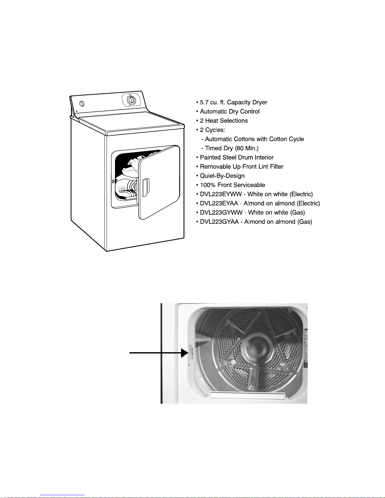
DVL223EY/GY - GE 5.7 Cu. Ft. Large Capacity Dryer
IN
0 M
8
Y
R
D
D
E
M
I
T
70
RY
T
D
A
E
SS
H
LE
M
U
I
D
E
M
C
I
T
A
M
O
T
U
A
60
S
N
O
T
T
O
C
2 Cycle Automatic Heavy D
uty Large Capacity
T
A
E
H
H
G
I
H
50
40
0
3
Y
E DR
OR
M
20
G
N
I
T
T
E
S
R
A
L
U
G
E
R
D
E
R
R
E
F
E
R
P
=
T
R
A
T
S
T
R
A
T
S
Features and Benefits
™
Model Nomenclature
3
Page 6
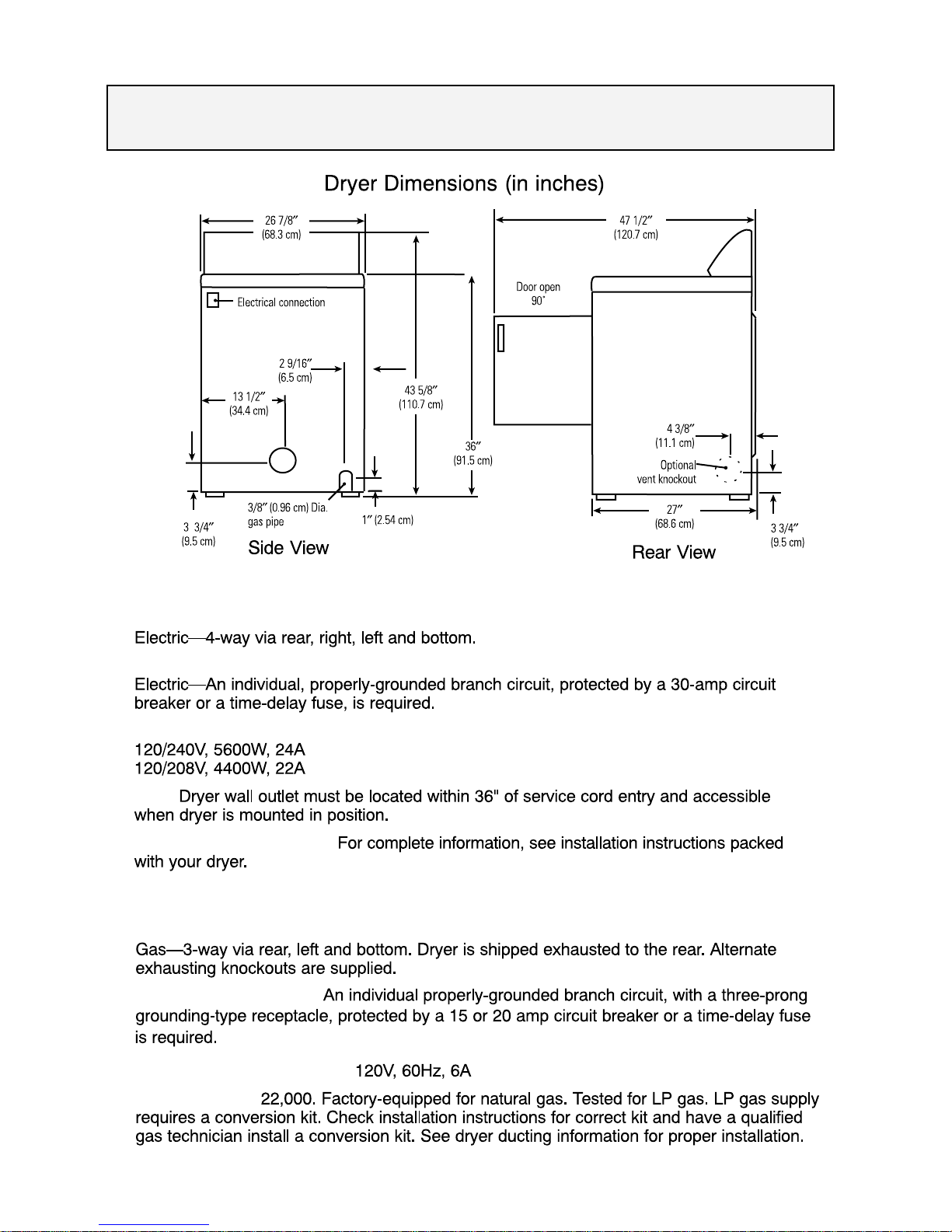
Installation Specifications
Electric Dryer
Exhaust Options:
Circuit Requirements:
Electric Dryer Rating:
Note:
Installation Information:
Gas Dryer
Exhaust Options:
Circuit Requirements:
Gas Dryer Electric Rating:
Gas (BTU/HR):
4
Page 7
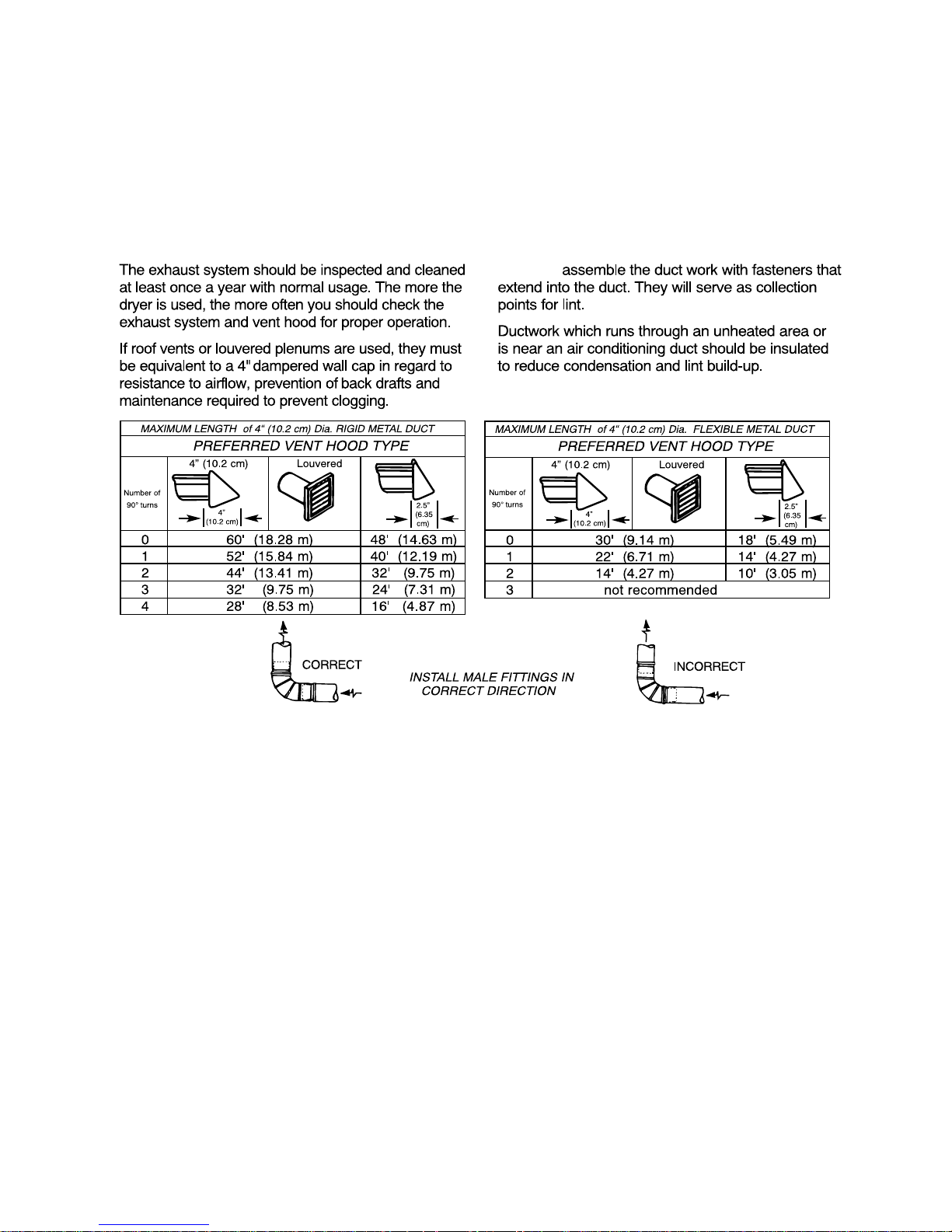
Exhaust Ducting Length
•
DO NOT
•
NOTE: When exhausting from the side or bottom, a vent kit is available as publication
#14-A018. The vent kit replaces the existing duct inside the dryer to allow a 90° elbow
to vent the dryer out the side or bottom. The kit consists of a 6 1/2” long, 4” diameter
metal duct with attached mounted bracket and instructions. A 90° elbow is not supplied
and must be provided by the installer.
5
Page 8
DRYER OPERATION
The dryer drum rotates clockwise at 48 – 54 rpm
as viewed from front. On electric models, air is
drawn into the heater housing and across the
open coils of the electric heater. On gas models,
air is drawn into the combustion chamber and over
the burner flame. The air is then pulled through
the tumbling clothes, picking up moisture and lint.
Lint is filtered out as air passes from the drum,
across the filter screen and into the blower duct,
where it is discharged out the vent. The bias
control thermostat, according to the setting of the
fabric selector switch, controls the air temperature.
The length of the drying cycle is controlled by the
number of minutes selected on the timer or automatically controlled by the timer, in conjunction
with the thermostat, for the type of fabric selected
(automatic dry cycles).
ACCESSING THE DRYER COMPONENTS
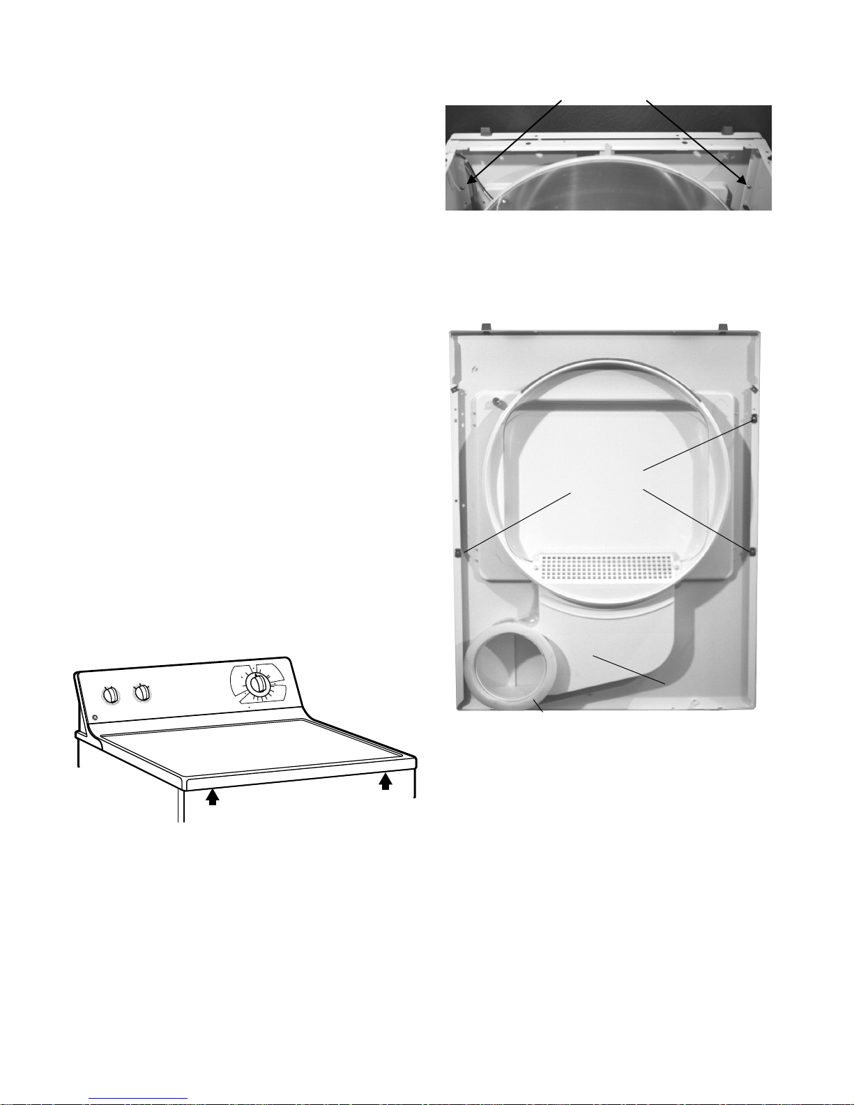
Top Panel Removal
The top panel is held in place by two spring clips
located at the front of the dryer and two tabs located
at the back. To release the clips, use a stiff putty
knife inserted between the top and front panel at
the locations shown at right. Holding the putty knif e
in a horizontal position, push in on one spring clip to
release that edge of the top. Repeat with the other
clip, lift the top at the front and disengage it from the
tabs at the rear.
2 Phillips screws
Starting at the top edge, pull the front panel forward.
3 guide clips align the front panel to the sides. Once
the clips are released, lift the front panel to remove.
Guide Clips
ORE DRY
M
C
I
T
A
M
O
T
U
A
LESS DRY
E
R
U
T
A
R
E
P
M
E
T
T
R
A
T
S
MEDIUM
FLUFF
START
HIGH
m
to
u
A
le
c
y
C
3
LESS DRY
C
I
T
A
M
O
T
U
A
S
N
O
T
T
O
C
ORE DRY
M
ity
c
a
p
a
C
e
rg
a
L
ty
u
D
y
v
a
e
H
tic
a
20
40
30
= PREFERRED REGULAR SETTING
T
N
E
N
A
M
R
E
P
S
S
L
E
O
O
R
C
P
N
W
O
D
IN
80 M
70
Y
R
D
D
E
M
I
T
60
50
Front Panel Removal
The remove the front panel, disconnect power and
remove the top panel. Once the top panel is off,
remove the two Phillips screws, one on each side,
located on the top inside edge of the front panel.
Disconnect the two wires from the door switch.
Air Duct
Air Duct Seal
Front Panel Air Duct
The front panel air duct is glued to the front panel.
Should the air duct need to be replaced, an air duct
seal will also be required. The foam air duct seal is
gluded to the air duct and seals between the duct
and the opening for the blo wer wheel on the blo wer
housing. To replace the air duct or install a replacement front panel, remove the front panel, remove
the lint filter, remove the 2 Phillips screws from the
lint trap cover and remov e the lint tr ap cov er . Using
a sharp knife, cut the adhesive between the air duct
and the front panel. If reinstalling the original front
panel, use a putty knife to remove as much of the
old adhesive as possible. Apply adhesive along the
edge of the air duct and position it on the front panel.
6
Page 9
Apply a bead of WH60X20 adhesive on the air duct
seal and position it on the air duct. Reinstall the lint
trap cover and filter, front and top panel.
Door Gasket
The door gasket is secured to the door panel by
tabs. To replace the gasket, pull the old gasket off
the inner door panel, align the new gasket tabs with
the slots in the door and press the gasket into place.
Door Handle
The door handle is secured to the outer door panel
by tabs. To replace the door handle, remove the
door from the front panel and remove the screws
from the sides and bottom of the door. Separate
the inner and outer door panels. Release the tabs
that secure the door handle to the front panel.
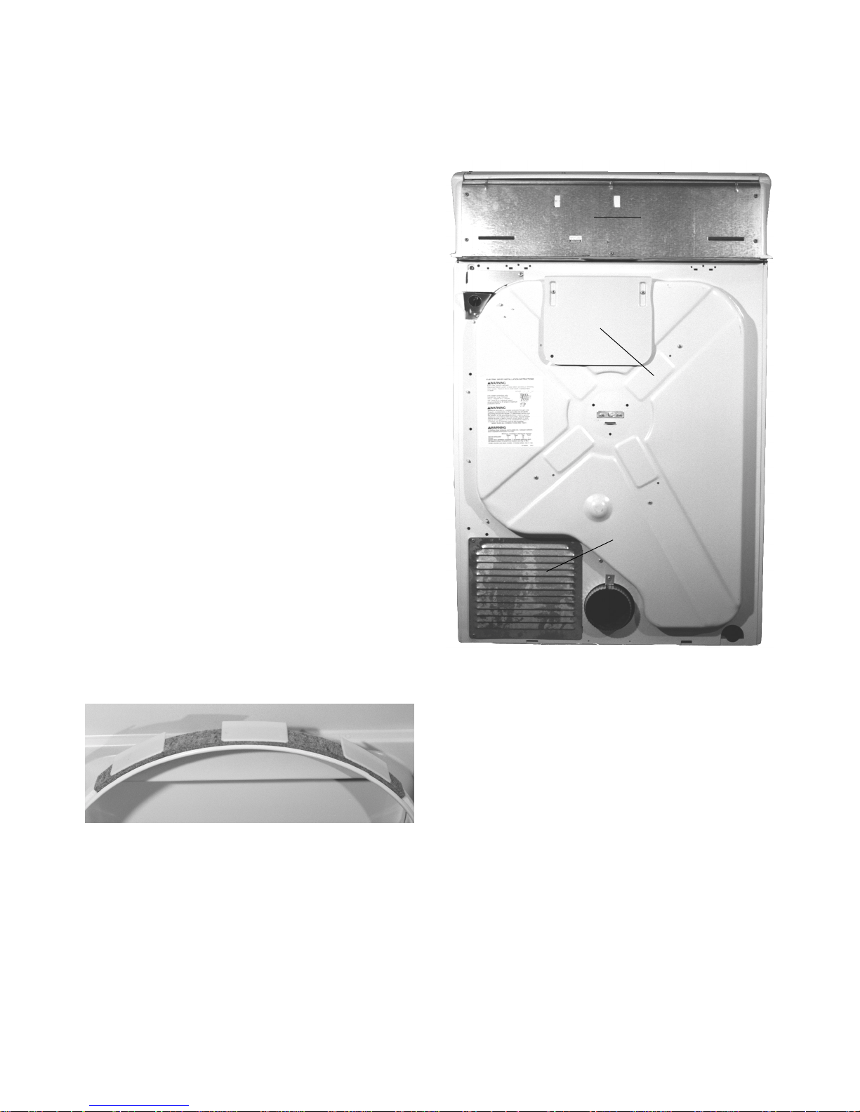
Rear Access Panel
The rear access panel allows access to view the
motor, centrifugal s witch, idler pulley assembly, belt
and belt switch. The panel is secured to the back b y
two Phillips screws.
Mini Manual
Heat Deflector Shield
Drum Glide and Upper Seal
The drum glide is glued to the top outer edge of the
door opening and is a part of the felt upper drum
seal. To replace the drum glide/upper seal assembly ,
raise the top panel, remove the two Phillips screws
on the front panel and pull the front panel towards
you. Remove the old seal assembly and glue the
new seal in place using WH60X20 adhesive.
Reinstall the front and the top panels.
Drum Glide and Upper Seal
Rear Access Panel
NOTE: Located on the rear of the dryer is a heat
deflector shield. The purpose of the shield is to
prevent someone from coming in contact with the
hot part of the cabinet near the heater. If y ou remove
the shield for any reason, make certain to reinstall
the shield upon dryer reassembly.
Lower Drum Seal
The lower drum seal is glued in place around the
outer lower edge of the door opening on the front
panel. To replace the lower seal, remove the top
panel and the front panel. Remo ve the old seal and
glue a new seal in place. Reinstall the front and top
panels.
7
Page 10
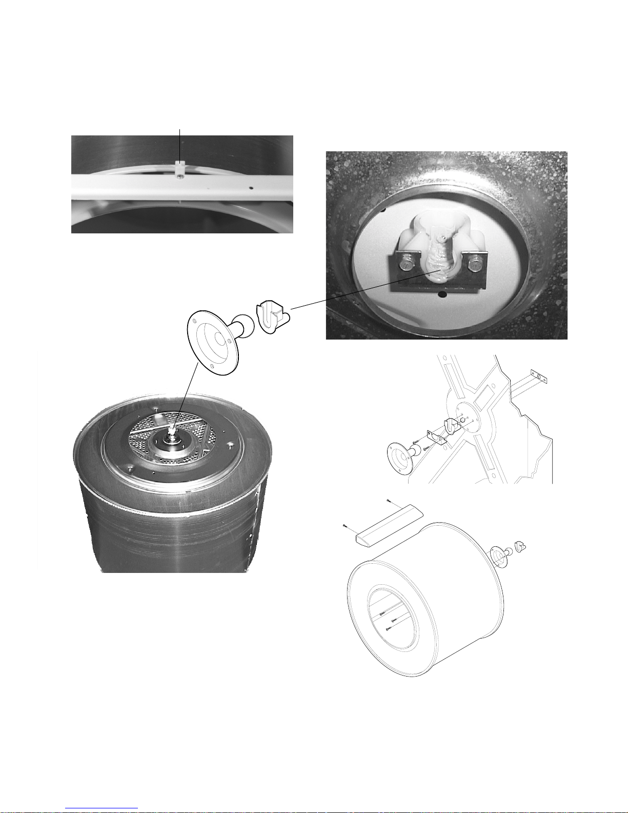
Dryer Drum Removal
Drum Bearing
To remove the dryer drum, disconnect power and
remove the top and front panels. Next, remove the
yellow spacer/bumper attached to the top cross
brace by a Phillips screw.
Drum Spacer/Bumper
Remove the drive belt from the motor drive pulley
by reaching under the drum from the front or through
the rear access opening. Once the belt is loose , the
drum must be lifted
straight up to disengage
the drum shaft from the
drum bearing. Once the
shaft ball is above the
drum bearing cup, pull the
Drum
Shaft
Drum
Bearing
drum forward through the
cabinet opening.
The drum bearing mounts to the inside rear of the
dryer cabinet by means of a sheet metal bracket
secured by two 5/16” screws. To replace, remove
the two screws holding the bearing to the back of
the dryer. Note: A small steel ball is used to keep
the shaft aligned in the bearing. Thoroughly lubricate
the new bearing with lithium grease and reassemble.
Drum Shaft
The drum shaft is attached to the drum by three
Torx screws. To replace the drum shaft, align the
mounting holes and use a piece of tape to hold the
shaft in place while installing the Torx screws from
inside the drum. Thoroughly lubricate the shaft ball
with Lubriplate or a high quality lithium grease.
Drum V anes
All three dryer drum vanes are replaceable. Each
vane is attached to the drum by two Phillips screws.
NOTE: If necessary, the drum shaft and bearing are
available as a kit under the part# WE25X10001. The
kit contains the drum shaft, shaft bearing, mounting
brackets , a steel ball, screws and a tube of Lubriplate,
a high quality lithium grease.
8
Page 11
Dryer Controls
Timer
To access the dryer controls, disconnect power and
remove the four Phillips screws at the top of the
switch trim. Grasp the trim at the top and pull forward.
Three tabs at the bottom fit into slots on the top panel.
Y
R
D
E
R
O
M
C
I
T
A
M
O
T
U
A
Y
R
D
S
Y
S
R
LE
D
S
S
S
M
IU
D
E
M
F
F
U
L
F
T
R
A
T
S
H
IG
H
e
H
tic
a
m
o
t
u
A
e
l
c
y
C
3
E
R
U
T
A
R
E
P
M
E
T
T
R
A
T
LE
C
I
T
A
M
O
T
U
A
S
N
O
T
T
O
C
Y
R
D
E
R
O
M
0
2
REFE
= P
y
it
c
a
p
a
C
e
g
r
a
L
ty
u
D
y
v
a
T
N
E
N
A
M
R
E
P
S
S
L
E
O
O
R
C
P
N
W
O
D
IN
M
0
8
70
Y
R
D
D
E
M
I
T
0
6
0
5
40
0
3
G
IN
SETT
R
LA
ED REGU
RR
Start Switch
The start switch energizes the start windings on the
drive motor. It is a momentary contact, rotary switch.
To test the switch, remove the wires and check for
continuity between the switch terminals. There
should be continuity only while turning the switch
clockwise. Once released, the terminals should read
open. Should the switch need to be replaced, turn
the switch clockwise (as viewed from the back) to
release it from the switch trim.
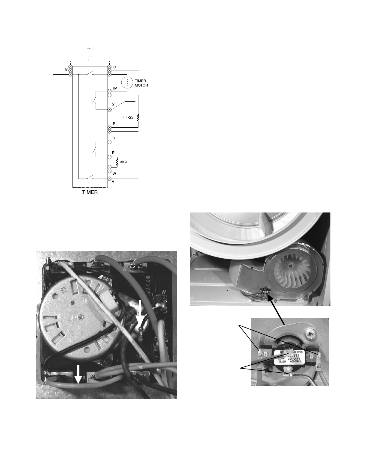
The timer is an electromechanical control with a 120v
drive motor. Depending upon the model, the timer
will control cycles for timed fluff (no heat), timed dry ,
automatic cottons and/or automatic permanent
press. On a timed cycle, the timer motor receives
120 volts continuously for the number of minutes
selected for the cycle. When an automatic cycle is
chosen, the time will vary based of the quantity of
clothes and their moisture content. When the heat
source is on, the timer motor does not receive power .
When the clothes warm and the control thermostat
is satisfied, the heat is turned off and voltage is then
supplied to the timer motor. When the thermostat
cools, the heat is again turned on and the timer stops.
As the clothes dry, the control thermostat reaches
temperature faster and the timer motor receives
power more often until the end of cycle is reached.
Temperature Selector Switch
The rotary temperature selector switch, one of the
controls on the model DBL333, allows the customer
to select different temperature settings for drying.
The switch contains a 3K ohm resistor on the electric
model and a 2.4K ohm resistor on the gas model.
On the “Medium” setting, the selector switch
activates a control thermostat bias heater, which is
in series with the resistor on the switch. To check
the switch, disconnect power , remove the wires from
the switch and check
for continuity. With the
4
switch set on “Regular”
setting, there should be
continuity only between
terminals 1 and 2. On
the “Medium” setting,
there should be
continuity only between
terminals 3 and 4. On a “Fluff” setting, there should
be no continuity between either set of terminals.
3
Resistor
5
21
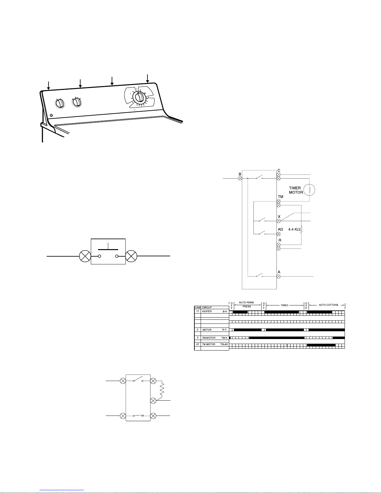
Timer Bar Chart
T o diagnose the timer , use the timer bar chart located
on the mini manual behind the switch trim. Rotate
the timer to a point in the particular cycle you want
to check. Find the appropriate location the timer
pointer is set in the cycles across the first column.
Read vertically down the chart from that point. At
each point you cross a shaded row, the contacts
listed at the left on the same row should have
continuity. Note the shaded areas are proportional
to the total time, so take several continuity
measurements at different points within the cycle
before determining the timer needs replacement.
9
Page 12
Depending on the dryer model, the timer can have
one or two resistors connected to it. Refer to the
wiring diagram with the dryer.
Automatic Dry
Resistor
Medium Heat
Resistor
On electric model dryers with an automatic dry cycle,
a 4.4K ohm resistor is used in series with the heater
to reduce the 240 volts to 120 volts and run the timer
motor when the control thermostat is open.
NOTE: The automatic dry cycle resistor resembles
a jumper wire between the terminals TM and R on
the timer.
Door Switch
The door switch is a normally open switch wired in
series with the drive motor. When the door is closed
and the motor running, a circuit is completed through
the motor’s run winding. To test the switch, remove
the top panel and wires from the switch. When the
door is closed, the switch should read continuity.
When the door is open, the switch should read open.
To replace the switch, squeeze the retaining clips
together and pull the switch from the front of the
dryer.
Control Thermostat and Bias Heater
The control thermostat regulates the temperature
inside the dryer drum. It is a single pole, single throw
switch wired in series with the high limit (or safety)
thermostat and the heat source. It is mounted on
the front of the blower housing. The control
thermostat also contains a bias heater. The purpose
of the bias heater is to apply a small amount of heat
to the control thermostat when the fabric selector
switch is set to the medium temperature setting. This
small amount of heat causes the thermostat to open
sooner to maintain a lower drum temperature.
MEDIUM HEAT
RESISTOR
4.4K OHM RESISTOR
A second type resistor will be used on gas or electric
model dryers with a medium heat setting. This
resistor is wired in series with the bias heater on the
control thermostat to cycle the thermostat at a lower
temperature.
To replace the timer, remove the timer knob and the
two Phillips screws under the knob .
THERMOSTAT
TERMINALS
BIAS HEATER
TERMINALS
NOTE:
The control thermostats are not interchangeable
between an electric and a gas dryer. The resistance
of the bias heater is 28K ohms on the electric dryer
and 7K ohms on the gas dryer.
10
Page 13

To check the control thermostat, remove the wiring
from the terminals. At room temperature, the
thermostat should have continuity between the
control thermostat terminals. To check the bias
heater, remove the wiring from the bias heater
terminals. Check the resistance between the bias
heater terminals. On an electric dryer, the resistance
should be 28K ohms. On a gas dryer, the resistance
should be 7K ohms.
To check for correct dryer temperatures, make
certain all panels are in place on the dryer and
remove the e xhaust venting from the rear of the dryer.
Place a thermometer capable of reading at least
300°F in the end of the dryer duct. Set the timer
and allow the dryer to operate for 10 minutes with
an empty drum. Check the temper ature immediately
after the thermostat has cycled off and the dryer
has reached its highest temperature. Depending
upon the cycle selected, the temperatures should
be between 165°F-195°F on a “High” setting and
between 150°F-180°F for a “Medium” setting. If the
complaint is long drying times and the temperatures
are correct, check for a restricted vent, too long a
vent run, or an excessiv e number of turns in the vent.
High Limit (Safety) Thermostat
THERMAL
LIMITER
HIGH LIMIT
SAFETY
THERMOSTAT
Thermal Limiter
The thermal limiter is wired in series with the drive
motor on all electric dryers. The purpose of the
thermal limiter is to shut down the dryer should the
control thermostat and the high limit thermostat fail
to open. Once the thermal limiter has opened, it
must be replaced. In addition, the condition that
caused it to open must be corrected. The most lik ely
cause would be an excessively long vent or a vent
with excessive turns. This is especially true if vinyl
or plastic venting was used.
The high limit (safety) thermostat is a single pole,
single throw switch wired in series with the control
thermostat. It is mounted towards the top of the
heater pan shield at the rear of the drum. If the
control thermostat should fail closed or an air
blockage occurs, raising the temperature in the
heater pan, the high limit thermostat opens the circuit
to the heat source.
HIGH LIMIT
SAFETY
THERMOSTAT
Heat System (Electric Dryers)
The heater assembly is located behind the dryer
drum. Holes in the back of the drum allow heated
air to be drawn into the drum. The heating element
is an open coil heater, attached to a metal shroud
with ceramic standoffs. Check the heating element
HEATER
TERMINALS
11
Page 14

by removing the drum and visually inspecting the
element for breaks. Remove the leads from the
heater terminals and check for 12 ohms across the
terminals, then check each terminal to ground. If
the element is open or grounded, replace the heating
assembly. To replace the heater assembly, remove
the four Phillips screws holding the assemb ly to the
cabinet back. Transfer the high limit (safety)
thermostat from the old heater shroud to the new
shroud and install the new assembly.
Heat System (Gas models)
Belt Switch
The belt switch is a normally closed switch and is
mounted on the motor bracket ne xt to the idler arm.
If the drive belt breaks or jumps off the idler pulley,
the idler arm will contact the belt switch, causing the
switch contacts to open, and thereby opening the
circuit to the motor. T o access the belt switch, remo ve
the access panel on the rear of the dryer. Remove
the leads from the switch and connect an ohmmeter
across the switch terminals. The ohmmeter should
read continuity when the belt is on.
The heating system for a gas dryer is comprised of
three main components, the ignitor, the flame sensor
switch, and the gas control valve.
The ignitor is a silicon carbide thermistor mounted
at an angle with the tip extending into the flame area.
Depending on room temperature, the resistance of
the ignitor should be between 50 to 400 ohms. The
ignitor is fragile and susceptible to contamination
from skin oils. Use only the ignitor’s insulated support
when handling to prevent damage . Electrically, the
ignitor is in parallel with the booster coil. The parallel
circuit of the ignitor and booster coil is in series with
the secondary coil on the gas valve. The series –
parallel circuit of the ignitor, booster coil, and
secondary coil is in tur n in parallel with the holding
coil on the gas valve. Note: During the auto dry
cycle, you will be able to read some voltage at the
ignitor whenever the dryer is operating.
The flame sensor switch mounts on the side of the
burner duct and is single pole, single throw switch.
When the ignitor reaches approximately 1800
O
F,
the flame sensor switch detects this high radiant heat
and opens. This energizes the secondary solenoid
gas valve coil, allowing gas to flow through the gas
valve . Gas flowing into the b urner duct is ignited by
the still hot ignitor. The flame within the b urner duct
heats the air being drawn into the back of the drum.
IGNITOR
BURNER ASSEMBLY
CENTRIFUGAL SWITCH
BELT SWITCH
Motor
The drive motor is a single speed, dual shaft, ¼ hp,
1725 rpm motor with an automatic reset overload
protector. The overload protector in an internal
component of the motor and cannot be replaced
separately. The motor shaft is threaded on one end
for the blo wer wheel, with the belt pulley on the other.
The pulley is not available separately and comes
pressed on the shaft of a new motor.
FLAME SENSOR
GAS V AL VE
12
Page 15

The motor contains a centrifugal switch which serves
three purposes: It disengages the motor start
winding, engages the motor run winding and closes
the circuit for the heat source. When the motor is
off, the switch completes a circuit from M5 through
the motor start winding to M4. The contact M1 to
M2 is open. Immediately as the motor is started,
centrifugal force pulls the switch activating collar in
on the motor. This opens the circuit through the
start winding and completes the circuit M6 through
the run winding to M4. The contacts M1 to M2 close
to activate the heat source.
MOTOR OFF
tape, two Phillips screws and the six clips holding
the cover in place.Note the retaining clips under the
aluminum tape at the bottom edge of the cover.
When reassembling, make certain the cover is
sealed to the housing with aluminum tape. If the
original tape cannot be reused, use aluminum tape
WD49X27 to seal the cover.
Unscrew the blower wheel in a clockwise direction
from the motor shaft using a 7/8” sock et on the blower
wheel and holding the motor shaft by the pulley. The
clockwise direction is marked on the center of the
wheel.
MOTOR RUNNING
T o chec k the switch, disconnect the dryer from power
and remove the drum. If the motor starts to run and
stops when the start switch is released, place an
ohm meter across terminals M5 and M6 and
manually pull in on the collar to activate the switch.
You should read continuity. If the motor runs and
there is no heat, activate the switch and check
between M1 and M2. You should read continuity.
Motor Removal
T o replace the motor , disconnect power , remov e the
top and front panels, belt and dryer drum. Remov e
the fan cover by carefully removing the aluminum
Direction
of removal
marked on
the blower
wheel
7/8”
hex nut
Once the blower wheel is unscrewed, remove the
motor mounting clip and unplug the wiring harness
from the motor.
MOTOR
MOUNTING
CLIP
WIRING HARNESS
F AN COVER
13
Page 16

Next, remove the fan housing lock from the rear of
the blower housing.
FAN
HOUSING
LOCK
MOTOR AND HARNESS WIRING
INTERNAL MOTOR WIRING
To remove the lock, insert a flat bade screwdriver
as shown below . Pry the lock away from the housing
far enough to clear the retaining tab and lift the lock
out of the channel.
O
Y
E
L
L
O
W
B
R
L
A
A
N
C
G
K
E
YELLOW
ORANGE
BLACK
3.4
4.3
9 8 7 6 5 3 1
G
N
D
TERMINALS
5 4 6 1 2
T
G
R
E
E
N
W
A
H
N
I
T
E
G
R
A
Y
HARNESS WIRING
Y
E
L
L
O
W
B
L
A
C
K
(Motor remove for clarity in illustrations)
FAN
HOUSING
LOCK
RETAINING
TAB
Once the lock is removed, the motor can be pulled
from the blower housing.
14
Page 17

DBL333E
15
Page 18

DBL333G
16
Page 19

DCL333E
17
Page 20

DCL333G
18
Page 21

DVL223E
19
Page 22

DVL223G
20
Page 23

Dryer Will Not Run
House fuse,
breaker, outlet
problem
Repair terminal
block connection.
Replace door
switch
Replace start
switch
Electric Dryer
N
N
N
N
Adequate voltage
to dryer?
Y
Connections at
terminal block
OK?
Y
Door switch
contacts closed?
Y
Start switch
contacts closed?
Y
House fuse,
breaker, outlet
problem
Replace door
switch
Replace start
switch
Replace timer
Gas Dryer
N
N
N
N
Adequate voltage
to dryer?
Y
Door switch
contacts closed?
Y
Start switch
contacts closing?
Y
Timer contacts
B & C closed?
Y
Replace timer
Replace thermal
limiter and
correct failure
fault
Replace belt
switch
Replace motor
N
N
N
N
Timer contacts
B & C closed?
Y
Contacts on
thermal limiter
closed?
Y
Belt switch
contacts closed?
Y
Check motor
centrifugal switch
reading between
contacts 4 & 5:
Or
Using a properly
grounded test
cord connected to
terminals 4 & 5
does the motor
run?
Y
Replace belt
switch
Replace motor
N
N
Belt switch
contacts closed?
Y
Check motor
centrifugal switch
reading between
contacts 4 & 5:
Or
Using a properly
grounded test
cord connected to
terminals 4 & 5
does the motor
run?
Y
Open wiring
between
components.
Locate and repair.
Open wiring
between
components.
Locate and repair
21
Page 24

No Heat - Drum Turns
Electric Dryer
House fuse,
breaker, wall
outlet problem
Replace power
cord
Replace timer
Replace
temperature
selector switch
Replace control
thermostat
N
N
N
N
N
Adequate voltage
to dryer at outlet?
Y
Correct voltage at
dryer terminal
block?
Y
Turn timer on
Contacts A & B
closed on the
timer?
Y
Contacts 1 & 2
closed on the
temperature
selector switch?
Y
Contacts on the
control thermostat
closed?
Not applicable
on all models
Replace hi limit
thermostat
Replace heater
Replace
motor
N
N
N
Open wiring
between
components.
Locate and repair
Y
Contacts on high
limit thermostat
closed?
Y
Heater resistance
OK?
Y
Continuity
between contacts
1 & 2 on
centrifugal
switch? Manually
move the switch
to run position to
check these
contacts
Y
22
Page 25

No Heat - Drum Turns
Gas Dryer
Ignitor glowing?
N Y
Replace flame
sensor
Replace timer N
Replace
temperature
selector switch
Replace control
thermostat
Replace high limit
thermostat
N
contacts closed?
Contacts A & B
Contacts 1 & 2
N
selector switch?
Contacts on the
control thermostat
N
Contacts on the
N
Flame sensor
Y
closed on the
timer?
Y
closed on the
temperature
Y
closed?
Y
high limit
thermostat
closed?
Fix supply
problem
Ignitor between
50 and 400 ohms
at room
temperature?
Y
Flame sensor
contacts open
after ignitor has
been on 15 to 90
seconds max.?
Y
Gas valve
solenoids check
OK?
Y
120 volts to gas
valve solenoids?
N
Y
N
N
N
N
Gas supply OK
to dryer?
Replace ignitor
Replace flame
sensor
Replace gas
valve assembly
Open wiring in
gas valve circuit,
locate and repair
Replace
motor
Open wiring to
one of the
components.
Locate and repair.
N
Continuity
between contact
1 and 2 on the
centrifugal
switch?
Manuall move the
switch to the run
position to check
the contacts.
Y
Y
Y
Replace gas
valve assembly
Not applicable
on all models
23
Page 26

No Medium Heat
Electric and Gas Dryers
Replace
temperature
selector switch
between contacts
N
Continuity
1 & 2 and 3 & 4
on temperature
selector switch?
N
Replace
temperature
selector switch
resistor
Replace
resistor
Replace
timer
Replace control
thermostat
Y
Resistor between
Y
Y
Y
timer contacts
Continuity between
timer contacts
Bias heater on
control thermostat
Resistor on
temperature
selector
switch open?
N
E & W
OK?
N
D & E?
N
open?
N
Open wiring to
one of the
components,
locate and repair
Not applicable
on all models
24
Page 27

Timer Will Not Advance On Auto-Cycle
Electric Dryer
Timer advances
but doesn't
Y N
complete cycle?
Replace timer N
Advance timer to
near end of cycle.
Continuity
between timer
contacts TM & X
and between
B & C?
Y
Open wiring or
connection in
circuit, locate and
repair
Gas Dryer
Turn timer on
Continuity
between timer
contacts
B & C?
Y
Timer motor OK?
Y
Resistor between
timer contacts
TM & R OK?
Y
Open wiring or
connection in
circuit, locate and
repair
Replace timerN
N
Replace resistorN
Replace timer N
Not applicable
on all models
Timer advances
but doesn't
Y N
Advance timer to
near end of cycle.
Continuity
between timer
contacts
TM & TD?
Y
Open wiring or
connection in
circuit, locate and
repair
complete cycle?
25
Turn timer on
Continuity
between timer
contacts
B & C and
TM & AD?
Y
Timer motor OK?
Y
Open wiring or
connection in
circuit, locate and
repair
Replace timerN
N
Page 28

Model DBL333EY0WW shown
26
Page 29

GE - DBL333EY0WW (ELECTRIC DRYER - CONTROLS AND TOP PANEL)
Ref No Part Number Description Qty
1 49-9996 USE & CARE MANUAL 1
1 31-15408 MINI MANUAL 1
7 WE02X10009 CLIP-TOP/FRONT PANEL 2
8 WE02X10021 SCR, 8-18 X .50 2
9 WE20X10010 PANEL BACK 1
13 WE04X10037 SELECTOR SWITCH 1
15 WE04X10033 SWITCH-START 1
18 WE19X10024 SWITCH TRIM 1
19 WE19X10020 END CAP R.H. WH 1
20 WE19X10022 END CAP L.H. WH 1
23 WEOBX10009 HARNESS-MAIN 1
26 WE19X10023 CONSOLE BOTTOM 1
29 WEOlXlOO33 KNOB ROTARY WH 1
30 WEOlXlOO34 COVER PLATE 1
31 WE01X10036 KNOB TIMER WH 1
36 WH02X10013 SCREW, 8,-18X1/2 5
50 WE08X10006 GROUND WIRE 1
53 WE20X10011 PANEL TOP WH 1
100 WH12X10079 TIMER 1
221 WHOlXlOO04 SCREW, 8-18AB X 0.375 14
1114 WE04XO752 RESISTOR- POWER,4.4K 1
1114 WE04XO744 RESISTOR,3.OK 1
1201 WE25X10001 REAR BEARING KIT 1
1205 WE01X1152 BALL 1
27
Page 30

Model DBL333EY0WW shown
28
Page 31

GE - DBL333EY0WW (ELECTRIC DRYER - FRONT PANEL & LINT FILTER)
Ref No Part Number Description Qty
209 WH02X10009 SCREW, 10-16X.50 2
1202 WEOlXlOO10 PLUG DOME WH 1
1208 WE18X10001 COVER LINT TRAP 1
1216 WE02X10010 CLIP-WIRING 2
1220 WE03XO073 GLIDE-DRUM 1
1221 WE09XO105 SEAL BASKET LOWER 1
1222 WE20X10012 PANEL FRONT WH 1
1225 WEOlXlOO23 DOOR CATCH 1
1226 WE04X10034 SWITCH-DOOR W/O LITE 1
1227 WE18X10002 LINT TRAP 1
1228 WE02XO361 CLIP-GUIDE 3
1234 WE14X10005 DUCT AIR 1
1241 WE01X10012 HINGE DOOR 2
1242 WH02X10038 SCREW, 8-18AB X 0.44 12
1244 WE09XO107 GASKET-DOOR 1
1246 WEOlXlOO13 DOOR HANDLE WH 1
1247 WElOX10008 DOOR-INNER WH 1
1248 WElOX10009 DOOR-OUTER WH 1
1249 WE01X1158 DOOR STRIKE 1
1271 WE09X10002 SEAL AIR DUCT 1
1279 WE01X10011 PLUG WH 4
29
Page 32

Model DBL333EY0WW shown
30
Page 33

GE - DBL333EY0WW (ELECTRIC DRYER CABINET & DRUM)
Ref No Part Number Description Qty
51 WE04XO716 BLOCK-TERMINAL 1
221 WHOlXlOO04 SCREW, 8-18AB X 0.375 14
1204 WE13X10010 BRACKET-CORD 1
1206 WE02XO358 BALL CLIP 1
1207 WE04X10026 INSULA TOR, HEATER HSG 1
1209 WE20X10009 ACCESS PANEL 1
1210 WE11X10002 HEA T SHIELD 1
1211 WE20X10005 COVER TERM BLOCK 1
1212 WE03XO070 BEARING-SHAFT 1
1213 WE13X10009 BRACKET-BEARING 1
1214 WE02X10005 SCREW, 10-16B X 1.375 2
1215 WE14X10016 HEATER HOUSING ASM 1
1217 WE14XO202 BAFFLE-HEATER 1
1218 WE02X10006 SCREW, 10-16 X .375 3
1223 WE21X10003 DRUM ASM 1
1229 WE02X10007 SCREW, 10-14 X 1.00 6
1230 WE21XO069 VANE 3
1232 WE13X10011 SHAFT SUPPORT 1
1233 WE04X10002 THERMOSTAT-SAFETY 1
1235 WE02X10008 SCREW, 6-20X.19 2
1236 WE04XO774 THERMAL LIMITER 1
1239 WE02X10011 SCREW, B-18 x .375 1
1240 WE02X10012 FOOT CABINET 4
1243 WE02X10020 SCREW, 10-32T X .375 1
1245 WE01X10035 PIN-LOCATING 2
1250 WE04X10027 BLOCK TERM HTR HSNG 1
1264 WE02X10013 CLIP, CABINET BTM 2
1319 WE02X10017 SCREW,10-16X.75 2
31
Page 34

Model DBL333EY0WW shown
32
Page 35

GE - DBL333EY0WW (ELECTRIC DRYER - MOTOR)
Ref No Part Number Description Qty
21 WR02X9494 SCREW,8-18 X 0.31 7
221 WH01X10004 SCREW, 8-18AB X 0.375 14
1304 WEOlXlOO16 LOCK FAN HOUSING 1
1310 WE14X10008 FAN HOUSING 1
1311 WE01X10029 SPACER-IDLER 1
1312 WE16X10001 BLOWER WHEEL 1
1313 WE14X10009 FAN COVER 1
1315 WE04X10028 THERMOSTAT-CONTROL 1
1320 WE02X10014 SCREW, 1/4-20T X 1.25 1
1321 WE02X10022 SCREW-STOP 1
1322 WEOlXlOO27 IDLER SPRING 1
1323 WEOlXlOO37 IDLER BRKT & PULLEY ASM 1
1325 WE12X10001 BELT-DRYER 1
1327 WE01X10003 MOTOR CLAMP 1
1328 WE17X10002 MOTOR & PULLEY 1
1345 WE02X10015 CLIP BLOWER HSG 6
1346 WE13X10006 MOTOR BRACKET 1
1347 WE09X10003 SEAL EXHAUST TUBE 1
1349 WE04X10030 BEL T SWITCH 1
1350 WE13X10008 BRACKET-BELT SWITCH 1
1381 WE14X10007 TUBE ASM EXHAUST 1
33
Page 36

Model DBL333GY0AAshown
34
Page 37

GE - DBL333GY0AA (GAS DRYER - BURNER)
Ref No Part Number Description Qty
21 WR02X9494 SCREW,8-18 X 0.3 17
221 WHOIX10004 SCREW, 8-18AB X 0.375 10
1319 WE02X10022 SCREW-STOP 1
1355 WE08X10003 HARNESS GAS VAL VE 1
1360 WE02X10018 CLIP WIRING, GAS BRACKET 1
1361 WE14X10010 BRACKET-BURNER 1
1364 WEOlXlOO19 PIPE 1
1365 WEOlXlOO20 CAP-PIPE 1
1366 WE14X10011 ELBOW-COUPLER 1
1368 WE01X1166 TAIL PIECE GAS VAL VE 1
1369 WE02XO371 NUT-UNION, GAS VALVE 1
1370 WE14XO207 GAS VALVE 1
1371 WE04X10020 COIL SECONDARY 1
1372 WE04X10031 COIL BOOSTER 1
1373 WE01X10022 ORIFICE 1
1374 WE04XO750 IGNITOR ASM 1
1377 WE14X10018 BURNER ASM 1
1379 WE04XO751 SENSOR 1
1380 WE14X10013 DUCT BURNER ASM 1
35
 Loading...