

Page 1
GE
g
Lighting Solutions
Dome Top Decasphere® Luminaire
READ THOROUGHLY BEFORE INSTALLING
WARNING
Risk of electric shock
• Turn power off before servicing
– see instructions
GEH-5827
INSTRUCTIONS
Make all electrical connections in accordance with
the National Electrical Code and any applicable
local code requirements.
Verify that supply voltage is correct by comparing
it to nameplate.
Replace power fuses only with fuses of the same
type and ratings.
GENERAL
This luminaire is designed for use in outdoor applications and must adhere to 25°C Max ambient temperature
limitation. Install and maintain it according to the
following recommendations.
CAUTION
Unit will fall if not installed properly
• Follow installation instructions
INSTALLATION
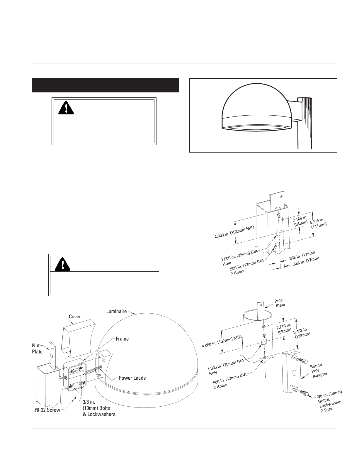
Step 1
A. Drill pole per Fig. A if a square pole or Fig. B if a
round pole.
Fig. A
Fig. B
These instructions do not purport to cover all details or variations in equipment nor to provide for every possible contingency to be met in connection with installation, operation
or maintenance. Should further information be desired or should particular problems arise which are not covered sufficiently for the purchaser’s purposes, the matter should be
referred to GE Lighting Solutions.
Page 2
B. Install Nut Plate and secure with 1/4” screw fur-
nished.
C. Attach Frame to luminaire feeding power leads
through Frame tube. Secure with (2) 3/8” bolts and
lockwashers.
D.Mount Frame/Luminaire Assembly to pole with (2)
3/8” bolts and lockwashers. If a round pole, install
Round Pole Adaptor.
E. Install cover over Frame and secure with #8-32
Screw.
F. Splice power leads to incoming power. Install pole
cap.
Strain relief for incoming power must be provided
in the pole top by the customer.
RELAMPING, CLEANING AND LIGHT
DISTRIBUTION CHANGES
CAUTION
Risk of burn
• Allow lamp/fixture to cool before
handling
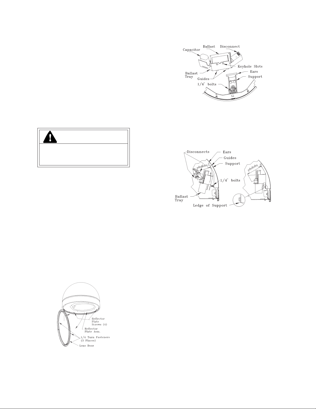
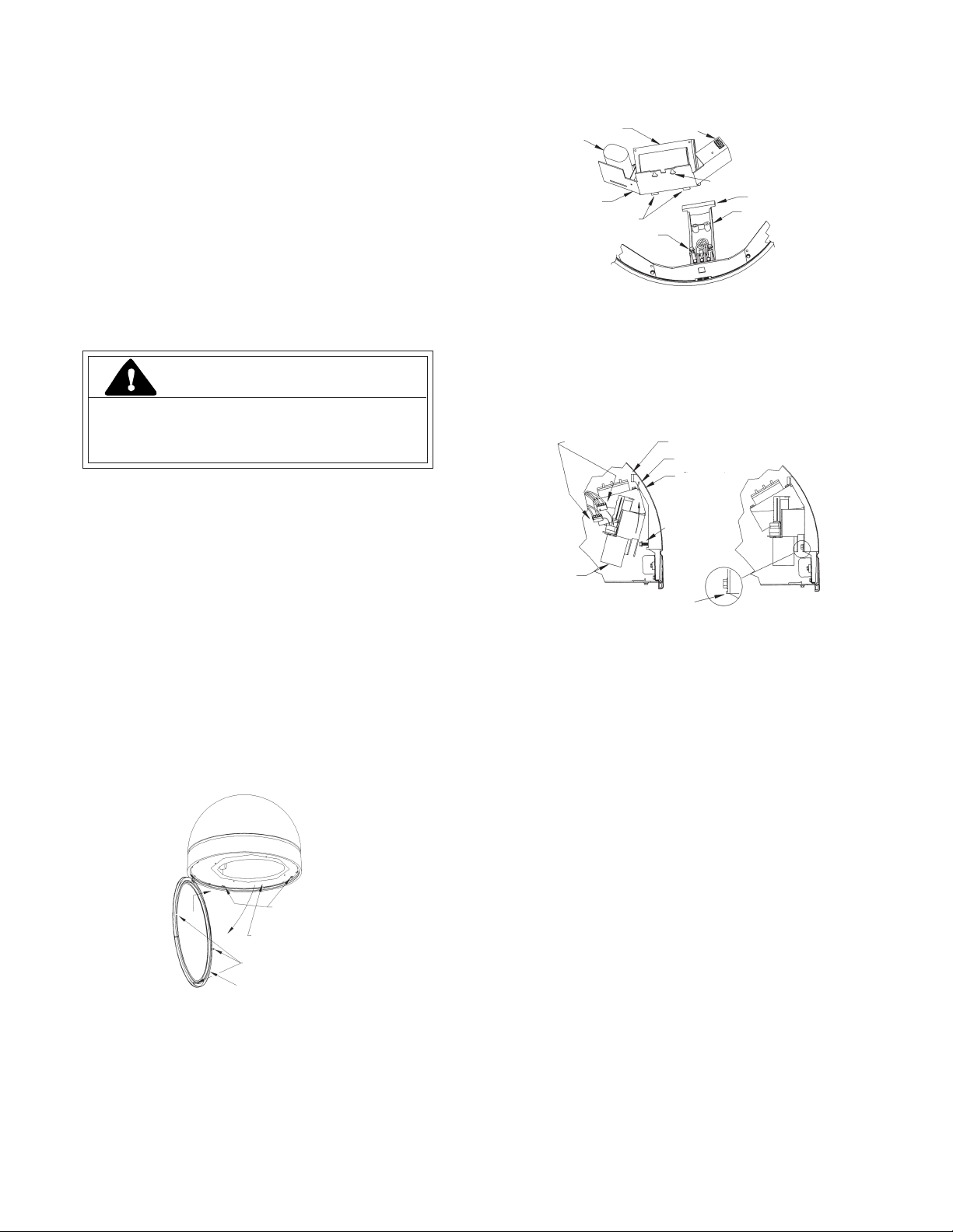
To Remove
Disconnect incoming power and lamp leads at the
electrical connectors. Loosen (2) 1/4” bolts, pull tray
out and drop to clear keyhole slots.
CAUTION: Be prepared to support the weight of the
ballast during removal.
To Install
Locate guide to each side of support. Slide tray up
under ears till 1/4” bolts can engage keyhole slots,
push in and up until tray is sitting on ledges of support. Tighten 1/4” bolts.
Use only lamps specified on nameplate. Observe
lamp manufacturer’s recommendations and
restrictions on lamp operation, particularly ballast
type, burning position, etc.
To Open Lens Door
Loosen (3) 1/4 turn fasteners by turning CCW.
Phillips screw driver required. Lens door is hinged on
pole side.
To Remove the Lens Door
Open to the position shown, lift and slide forward.
To Remove or Rotate the Reflector
Reflector may be removed to gain access to ballast and
wiring, or rotated 90° CW or CCW to orient light
distribution by loosening screws at each of (4) keyhole
slots in reflector plate assembly.
Assembly is tethered to luminaire. If it is necessary to
detach the assembly, remove screw that holds tether to
reflector plate.
WIRING
IF SINGLE VOLTAGE:
All single voltage ballasts are pre-wired such that user
need only connect the supply conductors.
IF MULTIVOLT: (120/208/240/277)
Connect the ballast lead with the insulated terminal to
the desired voltage terminal as indicated on the ballast
terminal nameplate.
IF MULTIWATT:
Multiwatt ballasts are available in various combinations of
wattage. See wiring instructions on wiring tag inside the
luminaire.
Removal of ballast tray may be required for access to
ballast terminals. Follow instructions for ballast tray
removal and installation as outlined above. Move insulated terminal to appropriate ballast terminal specified
on wiring tag inside luminaire.
BALLAST TRAY REMOVAL AND INSTALLATION
Open lens door and remove Reflector plate assembly
per instructions above,
CLEANING INSTRUCTIONS AND CAUTIONS
Internal
Should internal reflector system require cleaning, use
only non-abrasive, neutral (pH 6-8) cleaner contain-
ing no chlorinated or aromatic hydrocarbons. Rinse
clean and wipe.
External
Clean glass lens with a mild soap and water solution,
rinse clean and wipe dry.
Page 3

GE
g
À LIRE AVEC SOIN AVANT D'INSTALLER
Lighting Solutions
DANGER
Risque d’électrocution
• Mettre hors tension avant d’intervenir
– Suivez les instructions
GEH-5827
INSTRUCTIONS
Luminaire à dôme Decasphere
®
Effectuez tous les raccordements en conformité
avec les normes nationales et les éventuels
règlements locaux applicables.
Vérifiez que la tension secteur disponible est la
bonne en comparant avec l'indication de tension
sur la plaque d'identification.
Remplacez les fusibles d’alimentation uniquement
avec d’autres de même type et même valeur.
PRÉSENTATION
Ce luminaire est conçu pour des utilisations à l’extérieur et est
soumis à une limitation maximale de température ambiante de
25°C. Installez et entretenez-le en suivant les instructions suivantes.
ATTENTION
Risque de chute en cas de mauvais
montage • Suivez les instructions
LUMINAIRE
COUVERCLE
INSTALLATION
ÉTAPE 1
A. Percez le poteau comme au schéma A s’il est carré ou comme
au schéma B s’il est rond.
Schéma A
TROUS
2 TROUS
Schéma B
PLAQUE DE
POTEAU
PLAQUE
ÉCROU
BOULONS ET
#8-32 VIS
Ces instructions n'ont pas pour destination de couvrir tous les détails ou variantes de l'équipement, ni de répondre à toutes les éventualités que vous pourriez rencontrer pendant
l'installation, le fonctionnement ou l'entretien. Si vous souhaitez des informations complémentaires, ou si vous rencontrez un problème particulier qui ne soit pas adressé de votre point
de vue d'acheteur, le sujet doit être remonté jusqu'à la société GE Lighting Solutions
ÉCROUS
FREINÉS
.3/8 in. (10mm)
MONTURE
FILS
D’ALIMENTATION
TROUS
2 TROUS
ADAPTATEUR
POUR POTEAU
ROND
2 JEUX DE
BOULONS ET
ÉCROUS
FREINÉS 3/8 in.
(10mm)
Page 4
B. Installez la plaque à écrous et fixez-la avec la vis de
1/4 de pouce fournie.
C. Attachez la monture au luminaire en glissant les fils
d’alimentation au travers du tube de monture. Fixez avec
deux boulons de 3/8” et leurs rondelles-freins.
D. Montez l’ensemble monture/luminaire sur le poteau avec
deux boulons de 3/8” et leurs rondelles-freins. Si c’est un
poteau rond installez un adaptateur.
E. Installez le couvercle sur la monture et fixez-le avec la
vis
#8-32.
F. Faites la jonction des fils du luminaire avec l’arrivée
secteur. Installez le chapeau de poteau.
Le client doit aménager une boucle de détente de contrainte
sur les fils en haut du poteau.
CHANGEMENTS DE LAMPE ET DE DISTRIBUTION
LUMINEUSE, NETTOYAGE
ATTENTION
Risque de brûlure
• Laissez le bloc d’ampoule refroidir
avant d'y toucher
N’utilisez que le type de lampe spécifié sur la
plaque d’identification. Observez les recommandations
et restrictions du fabricant sur le fonctionnement de
la lampe, en particulier pour le type de ballast, la
position d’utilisation, etc.
Ouverture de la porte de lentille
Desserrez (dévissage) d’1/4 de tour les trois attaches 3, au
moyen d’un tournevis cruciforme à tête Phillips. La porte de
lentille est sur charnière côté poteau.
Dépose de la porte de lentille
Ouvrez comme montré, soulevez et glissez vers l’avant.
Dépose ou rotation du réflecteur
Le réflecteur peut être ôté pour donner accès au ballast et
au câblage, ou tourné dans un sens ou l’autre de 90° pour
orienter la distribution lumineuse, en desserrant les vis des 4
trous en forme de serrure de l’assemblage de plaque de
réflecteur.
L’assemblage est amarré au luminaire. S’il faut le détacher,
enlevez la vis qui maintient son amarrage sur la plaque de
réflecteur.
Dépose
Débranchez l’arrivée secteur et fils de lampe au niveau des
bornes électriques. Desserrez 2 boulons 1/4”, tirez et
abaissez le caisson pour libérer les trous en serrure.
CONDENSATEUR
BALLAST
CAISSON DE
BALLAST
GUIDAGES
BOULONS 1/4 in. (6mm)
DÉCONNEXIONS
TROUS DE SERRURE
OREILLES
SUPPORT
ATTENTION : Soyez prêt à supporter le poids
du ballast pendant la dépose.
Pose
Localisez le guidage de chaque côté du support.
Glissez le caisson vers le haut sous les oreilles
jusqu’à l’engagement des boulons de 1/4” dans les
trous de serrure, poussez-le en avant et en haut
jusqu’à l’épaulement du support. Serrez les boulons
de 1/4”.
CAISSON DE
BALLAST
DÉCONNEXIONS
ÉPAULEMENT DE SUPPORT
OREILLES
GUIDAGES
SUPPORT
BOULONS 1/4 in.
(6mm)
CÂBLAGE
MONO-TENSION :
Tous les ballasts sont précâblés et l'utilisateur n'a qu'à relier
les fils d'alimentation pour la tension prévue.
MULTI-TENSIONS : (120/208/240/277 volts)
Reliez le fil de ballast avec sa terminaison isolée sur la
borne de tension adéquate comme indiqué sur la plaque du
ballast.
MULTI-PUISSANCES :
Les ballasts multi-puissances sont disponibles en diverses
combinaisons de wattages. Reportez-vous aux instructions de
câblage sur l'étiquette à l'intérieur du luminaire.
4 VIS DE
PLAQUE DE
RÉFLECTEUR
ASSEMBLAGE DE PLAQUE
DE RÉFLECTEUR
3 ATTACHES 1/4 DE
TOUR
PORTE DE LENTILLE
DÉPOSE/POSE DU CAISSON DE BALLAST
Ouvrez la porte de lentille et enlevez l’assemblage de plaque de
réflecteur comme indiqué plus haut.
GE Lighting Solutions • 1-888-MY-GE-LED • www.gelightingsolutions.com
16943533----888
GE Lighting Solutions is a subsidiary of the General Electric Company. Evolve and other trademarks belong to GE Lighting Solutions. The GE brand and logo are trademarks of the General Electric Company.
© 2011 GE Lighting Solutions. Information provided is subject to change without notice. All values are design or typical values when measured under laboratory conditions.
g
La dépose du caisson de ballast peut être nécessaire pour
accéder aux bornes de ballast. Suivez les instructions
précédentes pour cette dépose et la remise en place. Déplacez
la cosse isolée sur la borne de ballast appropriée spécifiée sur
l’étiquette de câblage à l’intérieur du luminaire.
INSTRUCTIONS DE NETTOYAGE
Interne
Si le système interne de réflecteur a besoin d’être nettoyé, il
faut un nettoyant non abrasif, neutre (pH 6-8) non chloré et
sans hydrocarbures aromatiques. Rincez à l’eau claire et
essuyez.
Externe
Lavez la lentille en verre avec une solution douce d’eau
savonneuse, rincez-la à l’eau claire et essuyez-la.
35-201578-1K (11/00)
 Loading...