

Page 1
GE
Lighting Solutions
Area Lighting
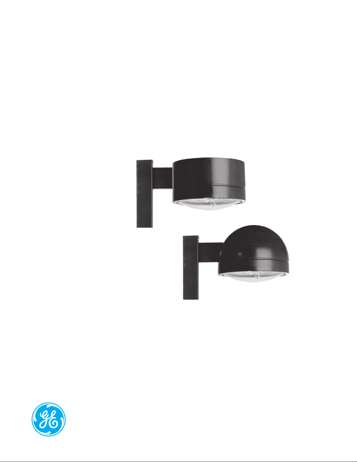
Decasphere™ (DCF & DCD)
imagination at work
Page 2

Product Features
Designed for superior photometric performance and architectural appeal, GE Outdoor Area Sightlighters provide
broad application flexibility. From parking lots to downtown areas, hospitals to shopping malls, business complexes
to residential neighborhoods, these fixtures will satisfy your large area lighting needs, while complementing your
aesthetic desires.
Applications
• Greater than 20 ft (6 meters) site lighting including
parking areas, driveways, malls and shopping
centers
• Commercial and industrial complexes, automobile
lots, residential areas and street lighting
Housing
• Spun aluminum housing and die- cast door
Finish
• Polyester powder paint finish standard in dark
bronze, black, white and aluminum
Rating
• 1598 Listed Suitable for Wet Locations
/
Mounting
Unique Features
• Heat and impact resistant tempered flat glass and
SAG glass lenses
• Vertical lamp square distribution reflector with SAG
glass only
• Enclosed, sealed and gasketed optical
• Terminal Board (Standard)
• Mogul base socket – E39 socket
• Magnapack packaging available
• Ballast tray standard
• Choice of 6-inch (152mm) arm or tenon top
mounting
Reflectors
• All reflectors are field rotatable
Page 3

Ordering Number Logic
Decasphere™ (DCF & DCD)
_ _ _ - _ _ - _ - _ - _ - _ - _ - _ _ _ - _ _ - _ - _
PROD. ID
DCF =
Decasphere
Luminaire Flat
Top
DCD =
Decasphere
Luminaire
Dome
WATTAGE
07 = 70
10 = 100
NOTE:
HPS only
15 = 150
(55V)
17 = 175
25 = 250
32 = 320
35 = 350
40 = 400
LIGHT
SOURCE
E = Energy
Act Compliant
Pulse MH
(EPMH)
S = HPS
P = Pulse
MH
Standard:
Mogul base
lamp not
included.
BALLAST
VOLTAGE COLOR
60Hz
0 = 120/208/240/
277 Multivolt
1 = 120
2 = 208
3 = 240
4 = 277
5 = 480
D = 347
F = 120X347
NOTE:
120 X 347
connected for
120V
TYPE
SELECTION
See Ballast and
Photometric
Selection Table
A = Autoreg
G = Mag-Reg
H = HPF Reactor
M = Mag-Reg
P = CWI with
with
Grounded
Socket Shell
or Lag
Grounded
Socket Shell
PE
FUNCTION
1 = None
2 = PE Receptacle
4 = PE Receptacle
and Shorting
Cap
NOTE: Receptacle
connected same
voltage as unit.
LENS
TYPE
G = Flat Glass
S = SAG Glass
IES
DISTRIBUTION
TYPE
See Ballast and
Photometric
Selection Table
MC2 = Medium
Cutoff Type II (flat
or SAG glass)
MC3 = Medium
Cutoff Type III
(flat or SAG glass)
FWT = Forward
Throw (flat or
SAG glass)
HTV = Horizontal
Type V (flat or
SAG glass)
AL = Aluminum
BL = Black
CG = Charcoal
Gray
DB = Dark Bronze
(Standard)
WH = White
AB = Aluminum
(Black
Reveal)
BW = Black (White
Reveal)
DW= Dark Bronze
(White
Reveal)
DK = Dark Bronze
(Black
Reveal)
WB = White (Black
Reveal)
For other colors
contact factory
MOUNTING
1 = 6-in. (152mm)
arm
E = 2-3/8”
External
Slipfitter (DCF
only)
R = No Arm (For
use with Top
Tennon
Accessory)
Ballast and Photometric Selection Table
All light sources are clear unless otherwise indicated.
Ballast Type/Voltage
Light 347
Wattage Source Multivolt 120 208 240 277 120X347 480 MC2 MC3 FWT HTV
60Hz
70, 100, 150 (55V) HPS H H, M M M M M M 179523 179530 179520 179534
250, 400 HPS A, M A,G,M A,H, M A,H, M A, M A,G,M A,M 179519 179529 179518 179533
175 EPMH A A A A A A A 179525 179532 179522 179536
250, 320 EPMH A A A A A N/A A* 179325 179532 179522 179536
350, 400 EPMH A A A A A N/A A* 179524 179531 179521 179535
*320 & 350 PMH N/A with 480V
IES Distribution Type
Photometric Curve Number 35Horizontal Lamp (Flat or Sagged Glass)
OPTIONS
C = Charcoal
Filter (except
on FWT)
F = Fusing (Not
avaiable with
multivolt or
120X347V)
J = Line Surge
Protector,
Expulsion Type
(UL not available)
N = Suitable for
high vibra tion
applications, such
as bridges and
over-passes
(tested to 3g
vibration)
(DCF only)
TOP TENNON ACCESSORY (Order fixture with “R” Mounting)
D4TA**-R-SGL = Single
D4TA**-R-D90 = Double at 90°
D4TA**-R-D180 = Double at 180°
D4TA**-R-T90 = Triple at 90°
D4TA**-R-Q90 = Quad at 90°
** Use same color code as fixture
NOTE: Ordering Numbers are
for dome top luminaires; add “F”
to Ordering Number for flat top
luminaires.
Page 4

Product Dimensions
DCF
DCD
23.58 in. (599 mm)
DRILLING TEMPLATE FOR SQUARE
POLE MOUNTING: STANDARD
.312 in. (6 mm) DIA
Hole
5.250 in.
(133 mm)
MIN
1.812 in.
(46 mm)
1.250 in. DIA
(32 mm DIA)
HOLE
.438 in. (11 mm) DIA
Holes
2.196 in. (56 mm)
4.392 in.
(112 mm)
.656 in. (17 mm)
1.312 in. (33 mm)
11.00 in.
(279 mm)
23.58 in. (599 mm)
21.46 in.
(545 mm)
DRILLING TEMPLATE FOR ROUND
POLE MOUNTING: MUST ORDER ROUND POLE ADAPTER
ACCESSORY SEPARATELY*
.312 in. (6 mm) DIA Hole
5.250 in.
(133 mm)
MIN
1.812 in.
(46 mm)
.750 in. DIA
(19 mm DIA)
HOLE
.438 in. (11 mm) DIA
2.719 in. (69 mm)
5.438 in.
(138 mm)
15.87 in.
(403 mm)
Holes
1/4-20 SCREW
NUT PLATE
#8-32 SCREW
DRILLING TEMPLATE
DRILLING TEMPLATE
POLE MOUNTING DETAIL
• Approximate Net Weight: 40-48 lbs (18-22 kgs)
• Suggested Mounting Height: 20-40 ft. (6-12 M)
DCD COVER
DCF COVER
• Effective Projected Area:
Flat Top 1.9 sq. ft. max. (0.18 sq. M max.)
DATA
ARM
DATA
*RPA**-DC for 3.5 to 4.5
inch (89-114) OD round
pole. Replace ** with
same color code as fixture
3/8-IN BOLTS
AND LOCKWASHERS
Dome Top 1.8 sq. ft. max. (0.17 sq. M max.)
GE Lighting Solutions • 1-888-MY-GE-LED • www.gelightingsolutions.com
1 - 8 8 8 - 6 9 - 4 3 - 5 3 3
GE Lighting Solutions, LLC is a subsidiary of the General Electric Company. The GE brand and logo are trademarks of the General Electric Company.
© 2012 GE Lighting Solutions, LLC. Information provided is subject to change without notice. All values are design or typical values when measured under laboratory conditions.
OLP-2944 (Rev. 06/19/12)
 Loading...