

Page 1
g
GE Consumer Service Training
TECHNICAL SERVICE GUIDE
COMMERCIAL DRYERS
Commerical Dryer
PERMAMENT PRESSPERMAMENT PRESS
SYNTHETIC KNITSSYNTHETIC KNITS
ASH
T W
HEA
COTTONS
T WITHT WITH
HIGH HEAHIGH HEA
COOL DOWN CYCLECOOL DOWN CYCLE
T
LOW HEALOW HEA
RESUME HEARESUME HEA
ART
PRESS TO STPRESS TO ST
TINGTING
OPERA
Add coins for extra dry time.Add coins for extra dry time.
1.
If dryer door is opened duringIf dryer door is opened during
2.
ART
cycle, push PRESS TO STcycle, push PRESS TO ST
button again to resume cycle.button again to resume cycle.
T
MODEL SERIES:
DCB330EY (Electric)
DCD330EY
DCB330GY (Gas)
DCD330GY
PUB # 31-9041 12/99
Page 2

Table of Contents
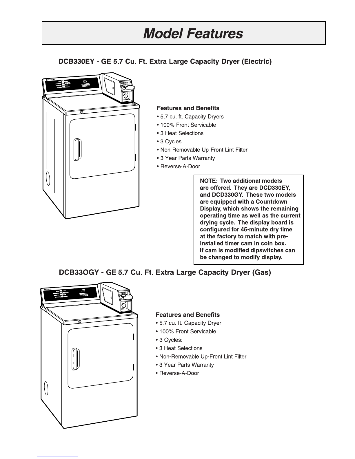
Model Series Features
Countdown (DCD Models)
Dimensions/Rating Plate
Installation Highlights
Top Panel/Front Panel
Lower Drum Seal
Drum Removal
Drum Shaft and Bearing
Dryer Controls
Timer/Accumulator
Door Switch
2
3-4
5
6-7
8
9
10
10
11
11
12
Control/Bias Thermostat
High Limit/Thermal Limit
Belt Switch
Motor
Motor Removal
Motor Harness/Wiring
Wiring Diagrams
Troubleshooting Flowcharts
Exploded Views/Parts List
12
13
14
15
16
16
17-18
19-21
22-41
1
Page 3
2
Page 4
3
Page 5
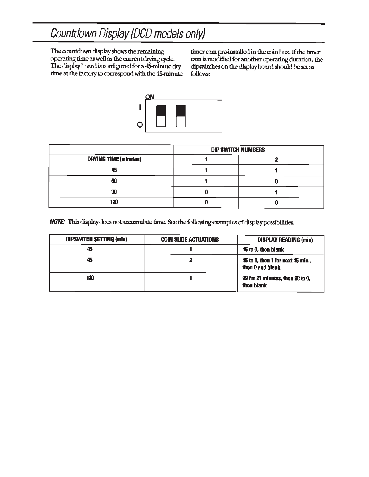
COUNTDOWN DISPLAY DIAGNOSTICS
To verify correct operation of Countdown
Display Board:
1. Make sure power is ON to dryer.
2. Advance coin box timer one cycle.
3. The display should read “88” for two to
three seconds, then default to the dip s witch
settings. (factory setting is “45”).
4. At the same time the “88” displa y is shown
the four indicator LED’s should light for 2-3
seconds. Next the “Press Start” LED will b link
and other indicator lights will go off. (if dryer
door is NOT open)
5. Replace the board if LED’s and Display
do not function as described in #3 and #4
above.
NOTE: The boar d does not control any cyc le
time duration of the dryer. The dryer will
function normally if there is a complete
failure of the board. It is the owners’
discretion whether or not the board should
be replaced.
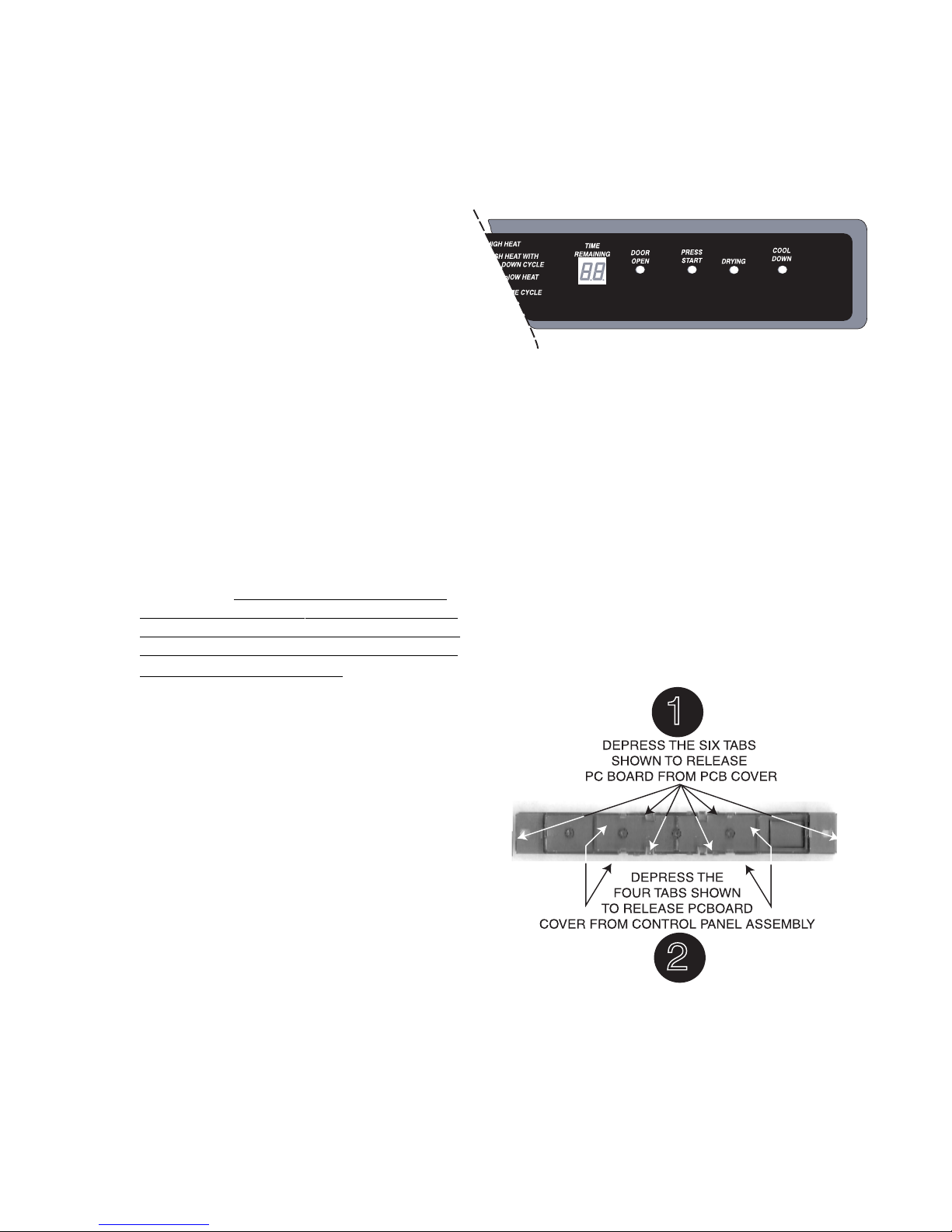
To replace Countback Display PC Board:
WARNING! THE STEP DOWN CAPACITOR
ON PC BOARD IS 120 VOLTS, AND POWER
MUST BE REMOVED PRIOR TO SERVICING.
THE TRACES ON THE BOARD R UNNING TO
THE CAPACITOR ARE HOT!
1. Remove the four screws in the top of
the control panel.
2. Disconnect harness connector to PC
board.
3. Pull 6 tabs as shown in illustration, one
at a time, starting at connector end,
while applying slight upward pressure,
until all tabs are released. Remove
PCboard.
4. With PCboard cover exposed, lift up on
either end of cover and release the
four tabs, one at a time until the cover
is release and remove.
5. To reinstall, align the PC board cover,
and press carefully. The tabs are
beveled to make installation easy.
6. Align PC board, by inserting the
counter end under the tab in plastic
pcboard cover at the counter opening,
and moving towards the connector
end, carefully press into place, so that
each tab snaps into place. Reconnect
harness connector, and reinstall.
control panel and four screws.
4
Page 6
PERMAMENT PRESS
HIGH HEA
T WITH
COOL DOWN CYCLE
LOW HEA
RESUME HEA
1.
2.
Add coins for extra dry time.
If dryer door is opened during
cycle, push PRESS TO ST
ART
button again to resume cycle.
SYNTHETIC KNITS
PRESS TO ST
ART
OPERA
TING
COTTONS
HEA
T W
ASH
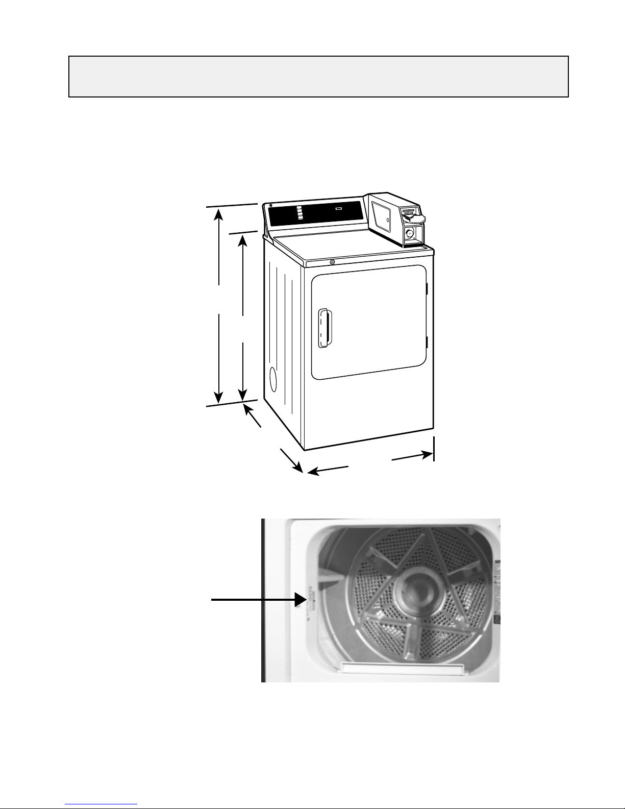
CABINET DIMENSIONS
DRYER CABINET DIMENSIONS
42"
36"
25-1/2"
Commerical Dryer
N
W
O
D
L
S
O
S
O
E
C
R
P
T
N
E
M
A
M
R
E
P
T
A
E
H
W
O
L
S
IT
N
K
C
I
T
E
H
T
N
Y
S
T
A
E
H
E
M
U
S
E
R
T
R
A
T
S
O
T
S
S
E
R
P
e.
xtra dry tim
d coins for e
Ad
.
1
ed during
pen
or is o
r do
rye
If d
.
2
T
R
A
T
O S
T
SS
RE
sh P
, pu
ycle
c
.
ycle
e c
sum
re
to
ain
ag
utton
b
¨
27"
G
TIN
ERA
P
O
H
S
A
W
T
A
E
H
S
N
O
T
T
O
C
H
IT
W
T
A
E
H
H
G
I
H
E
L
C
Y
C
Rating Plate with
Model/Serial Number
5
Page 7

6
Page 8

NOTE: When exhausting from the side or bottom, a vent kit is available as publication
#14-A018. The vent kit replaces the existing duct inside the dryer to allow a 90° elbow
to vent the dryer out the side or bottom. The kit consists of a 6 1/2” long, 4” diameter
metal duct with attached mounted bracket and instructions. A 90° elbow is not supplied
and must be provided by the installer.
7
Page 9
DRYER OPERATION
PERMAMENT PRESS
HIGH HEA
T WITH
COOL DOWN CYCLE
LOW HEA
RESUME HEA
1.
2.
Add coins for extra dry time.
If dryer door is opened during
cycle, push PRESS TO ST
ART
button again to resume cycle.
SYNTHETIC KNITS
PRESS TO ST
ART
OPERA
TING
COTTONS
HEA
T W
ASH
The dryer drum rotates clockwise at 48 – 54 rpm
as viewed from front. On electric models, air is
drawn into the heater housing and across the
open coils of the electric heater. On gas models,
air is drawn into the combustion chamber and over
the burner flame. The air is then pulled through
the tumbling clothes, picking up moisture and lint.
Lint is filtered out as air passes from the drum,
across the filter screen and into the blower duct,
where it is discharged out the vent. The bias
control thermostat, according to the setting of the
fabric selector switch, controls the air temperature.
The length of the drying cycle is controlled by the
number of minutes selected on the timer or automatically controlled by the timer, in conjunction
with the thermostat, for the type of fabric selected
(automatic dry cycles).
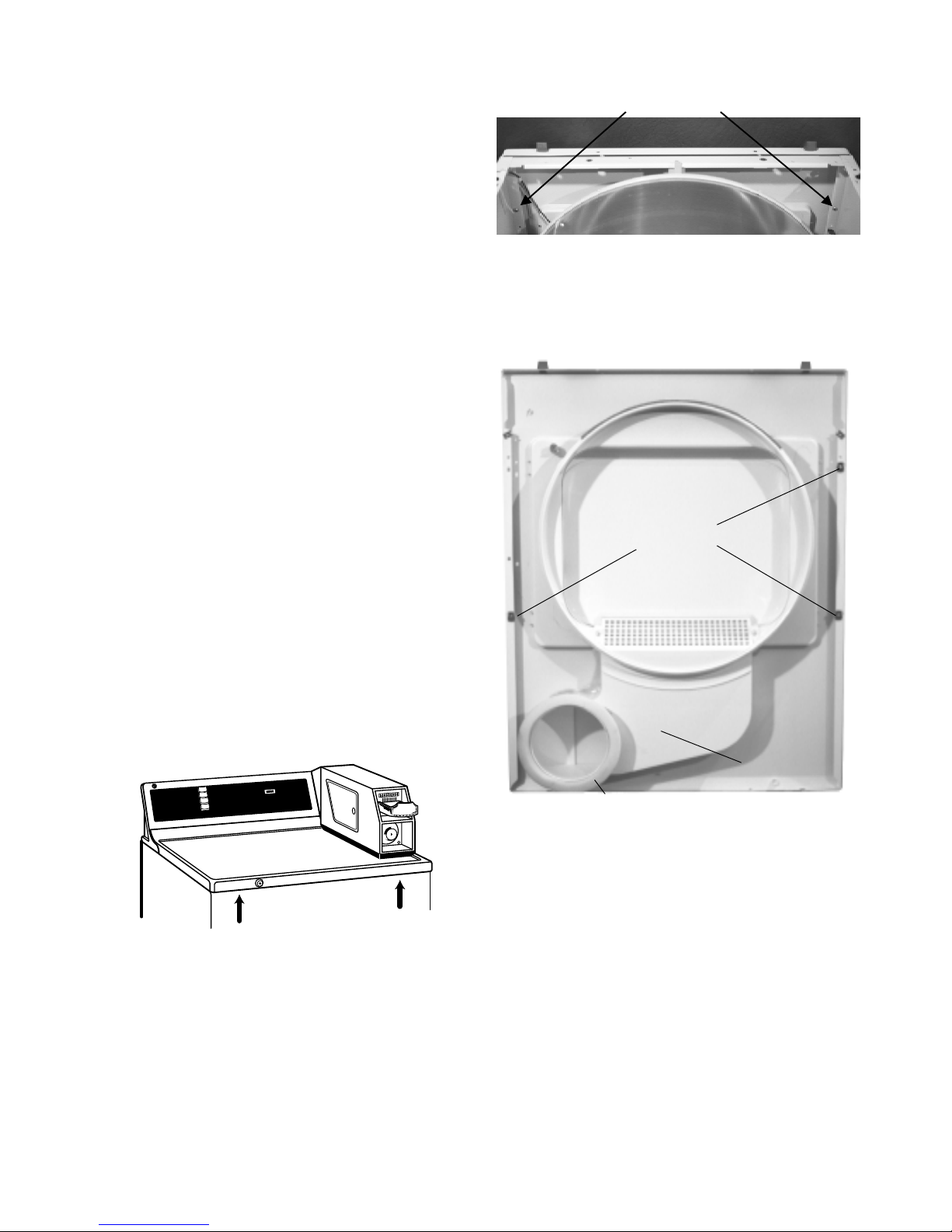
ACCESSING THE DRYER COMPONENTS
Top Panel Removal
The top panel is held in place by two spring clips
located at the front of the dryer and two tabs located
at the back. To release the clips, use a stiff putty
knife inserted between the top and front panel at
the locations shown at right. Holding the putty knif e
in a horizontal position, push in on one spring clip to
release that edge of the top. Repeat with the other
clip, lift the top at the front and disengage it from the
tabs at the rear.
2 Phillips screws
Starting at the top edge, pull the front panel forward.
3 guide clips align the front panel to the sides. Once
the clips are released, lift the front panel to remove.
Guide Clips
Commerical Dryer
H
S
A
W
T
A
E
H
S
N
O
T
T
O
C
H
IT
W
T
A
E
H
H
IG
H
E
L
C
Y
C
N
W
O
D
L
S
O
S
O
E
C
R
P
T
N
E
M
A
M
R
E
P
T
A
E
H
W
O
L
S
IT
N
K
IC
T
E
H
T
N
Y
S
T
A
E
H
E
M
U
S
E
R
T
R
A
T
S
O
T
S
S
E
R
P
G
N
I
T
A
R
E
P
O
.
e
m
i
t
y
r
d
a
r
t
x
e
r
o
f
s
n
i
o
c
d
d
A
.
1
g
n
i
r
u
d
d
e
n
e
p
o
s
i
r
o
o
d
r
e
y
r
d
f
I
.
2
T
R
A
T
S
O
T
S
S
E
R
P
h
s
u
p
,
e
l
c
y
c
.
e
l
c
y
c
e
m
u
s
e
r
o
t
n
i
a
g
a
n
o
t
t
u
b
Front Panel Removal
The remove the front panel, disconnect power and
remove the top panel. Once the top panel is off,
remove the two Phillips screws, one on each side,
located on the top inside edge of the front panel.
Disconnect the two wires from the door switch.
Air Duct
Air Duct Seal
Front Panel Air Duct
The front panel air duct is glued to the front panel.
Should the air duct need to be replaced, an air duct
seal will also be required. The foam air duct seal is
gluded to the air duct and seals between the duct
and the opening for the blo wer wheel on the blo wer
housing. To replace the air duct or install a replacement front panel, remove the front panel, remove
the lint filter, remove the 2 Phillips screws from the
lint trap cover and remov e the lint tr ap cov er . Using
a sharp knife, cut the adhesive between the air duct
and the front panel. If reinstalling the or iginal front
panel, use a putty knife to remove as much of the
old adhesive as possible. Apply adhesive along the
edge of the air duct and position it on the front panel.
8
Page 10
Apply a bead of WH60X20 adhesive on the air duct
seal and position it on the air duct. Reinstall the lint
trap cover and filter, front and top panel.
Door Gasket
The door gasket is secured to the door panel by
tabs. To replace the gasket, pull the old gasket off
the inner door panel, align the new gasket tabs with
the slots in the door and press the gasket into place.
Door Handle
The door handle is secured to the outer door panel
by tabs. To replace the door handle, remove the
door from the front panel and remove the screws
from the sides and bottom of the door. Separate
the inner and outer door panels. Release the tabs
that secure the door handle to the front panel.
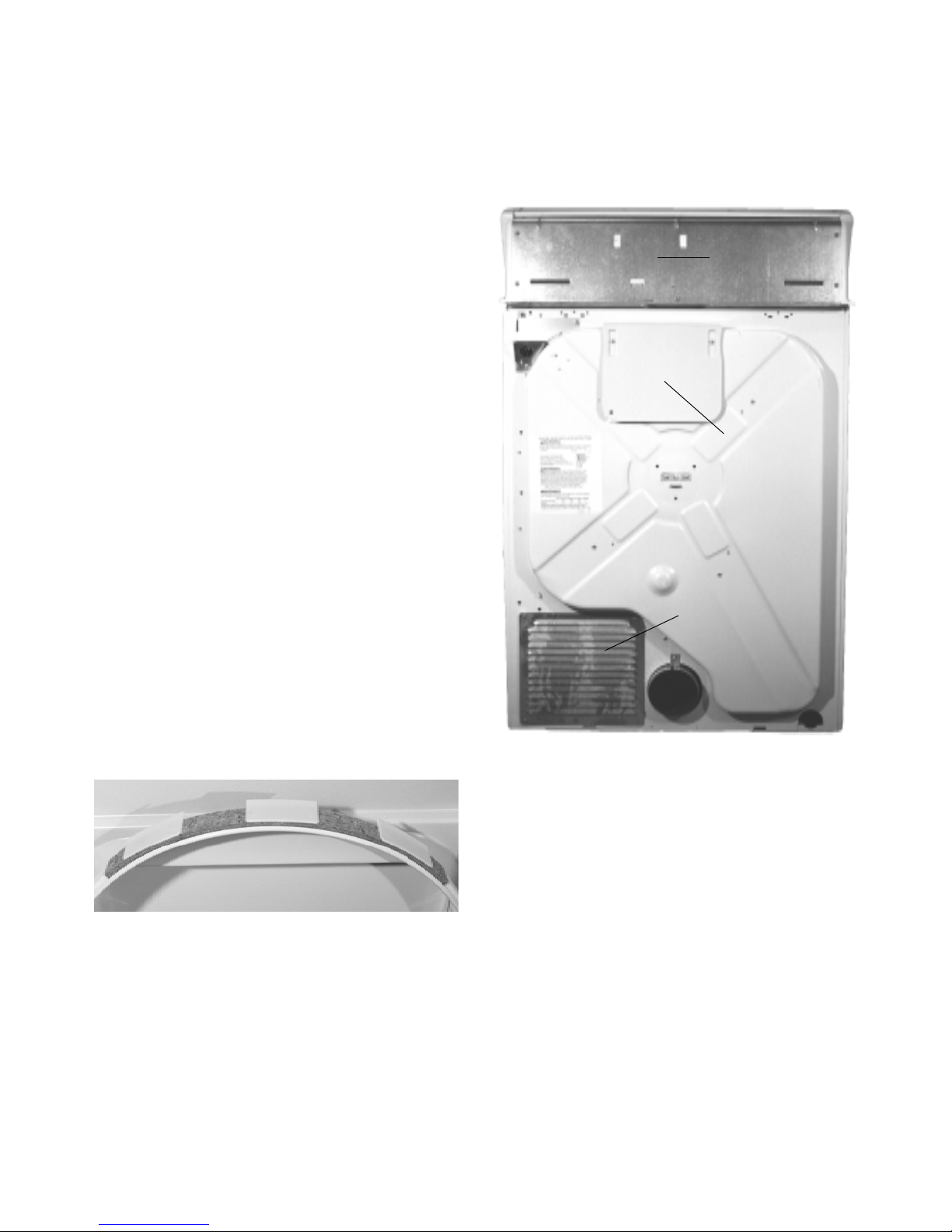
Rear Access Panel
The rear access panel allows access to view the
motor, centrifugal s witch, idler pulley assembly, belt
and belt switch. The panel is secured to the back b y
two Phillips screws.
Mini Manual
Heat Deflector Shield
Drum Glide and Upper Seal
The drum glide is glued to the top outer edge of the
door opening and is a part of the felt upper drum
seal. To replace the drum glide/upper seal assembly ,
raise the top panel, remove the two Phillips screws
on the front panel and pull the front panel towards
you. Remove the old seal assembly and glue the
new seal in place using WH60X20 adhesive.
Reinstall the front and the top panels.
Drum Glide and Upper Seal
Rear Access Panel
NOTE: Located on the rear of the dryer is a heat
deflector shield. The purpose of the shield is to
prevent someone from coming in contact with the
hot part of the cabinet near the heater. If y ou remove
the shield for any reason, make cer tain to reinstall
the shield upon dryer reassembly.
Lower Drum Seal
The lower drum seal is glued in place around the
outer lower edge of the door opening on the front
panel. To replace the lower seal, remove the top
panel and the front panel. Remo ve the old seal and
glue a new seal in place. Reinstall the front and top
panels.
9
Page 11
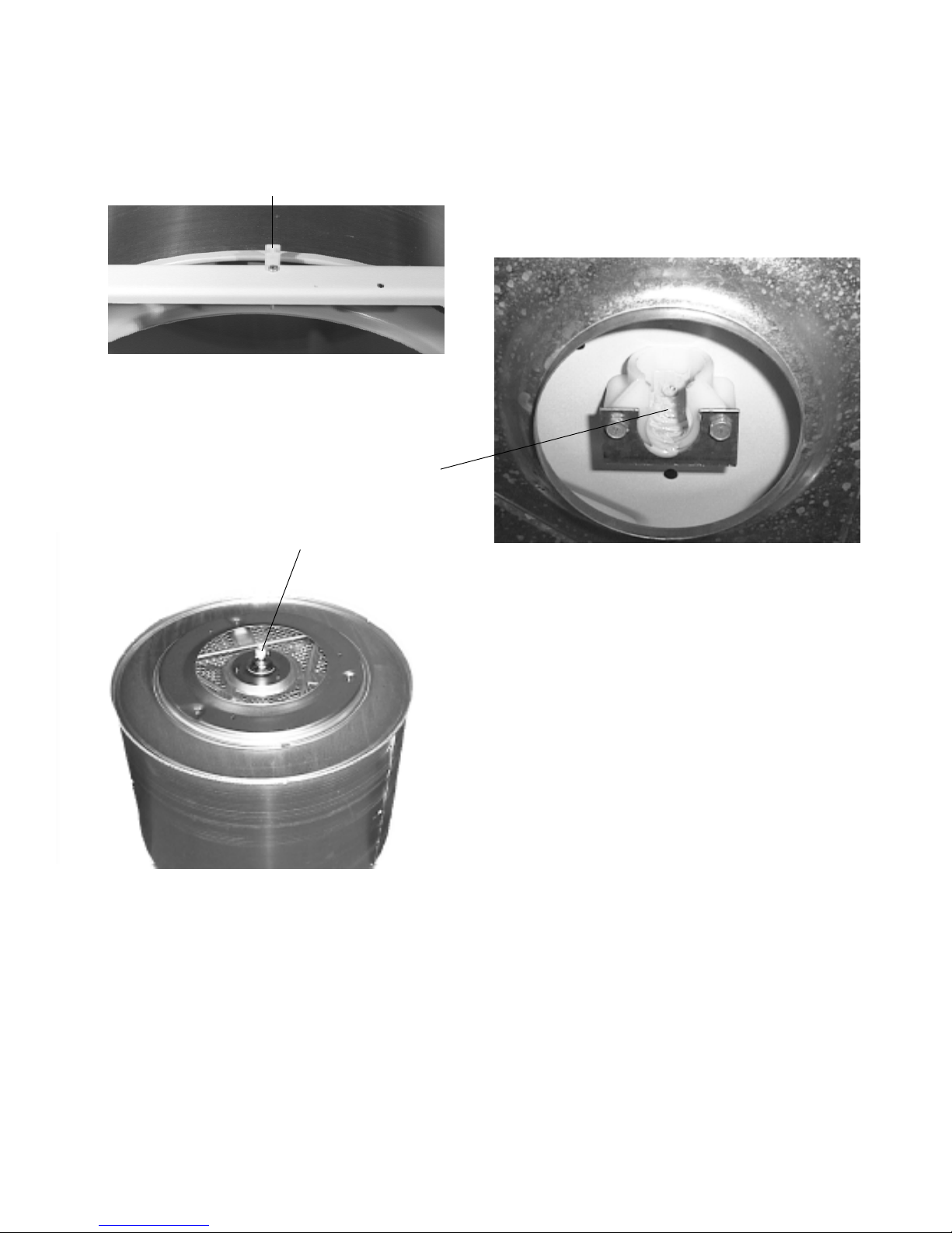
Dryer Drum Removal
Drum Bearing
To remove the dryer drum, disconnect power and
remove the top and front panels. Next, remove the
yellow spacer/bumper attached to the top cross
brace by a Phillips screw.
Drum Spacer/Bumper
Remove the drive belt from the motor drive pulley
by reaching under the drum from the front or through
the rear access opening. Once the belt is loose , the
drum must be lifted
straight up to disengage
the drum shaft from the
drum bearing. Once the
shaft ball is above the
drum bearing cup, pull the
drum forward through the
cabinet opening.
The drum bearing mounts to the inside rear of the
dryer cabinet by means of a sheet metal bracket
secured by two 5/16” screws. To replace, remove
the two screws holding the bearing to the back of
the dryer. Note: A small steel ball is used to provide
a grounding path. Make certain the steel ball is
installed during reassembly. Thoroughly lubricate
the new bearing with lithium grease and reassemble.
Drum Shaft
The drum shaft is attached to the drum by three
Torx screws. To replace the dr um shaft, align the
mounting holes and use a piece of tape to hold the
shaft in place while installing the Torx screws from
inside the drum. Thoroughly lubricate the shaft ball
with Lubriplate or a high quality lithium grease.
Drum V anes
All three dryer drum vanes are replaceable. Each
vane is attached to the drum by two Phillips screws.
NOTE: If necessary , the drum shaft and bearing are
available as a kit under the part# WE25X10001. The
kit contains the drum shaft, shaft bearing, mounting
brackets , a steel ball, screws and a tube of Lubriplate,
a high quality lithium grease.
10
Page 12
Dryer Controls
PERMAMENT PRESS
HIGH HEA
T WITH
COOL DOWN CYCLE
LOW HEA
RESUME HEA
1.
2.
Add coins for extra dry time.
If dryer door is opened during
cycle, push PRESS TO ST
ART
button again to resume cycle.
SYNTHETIC KNITS
PRESS TO ST
ART
OPERA
TING
COTTONS
HEA
T W
ASH
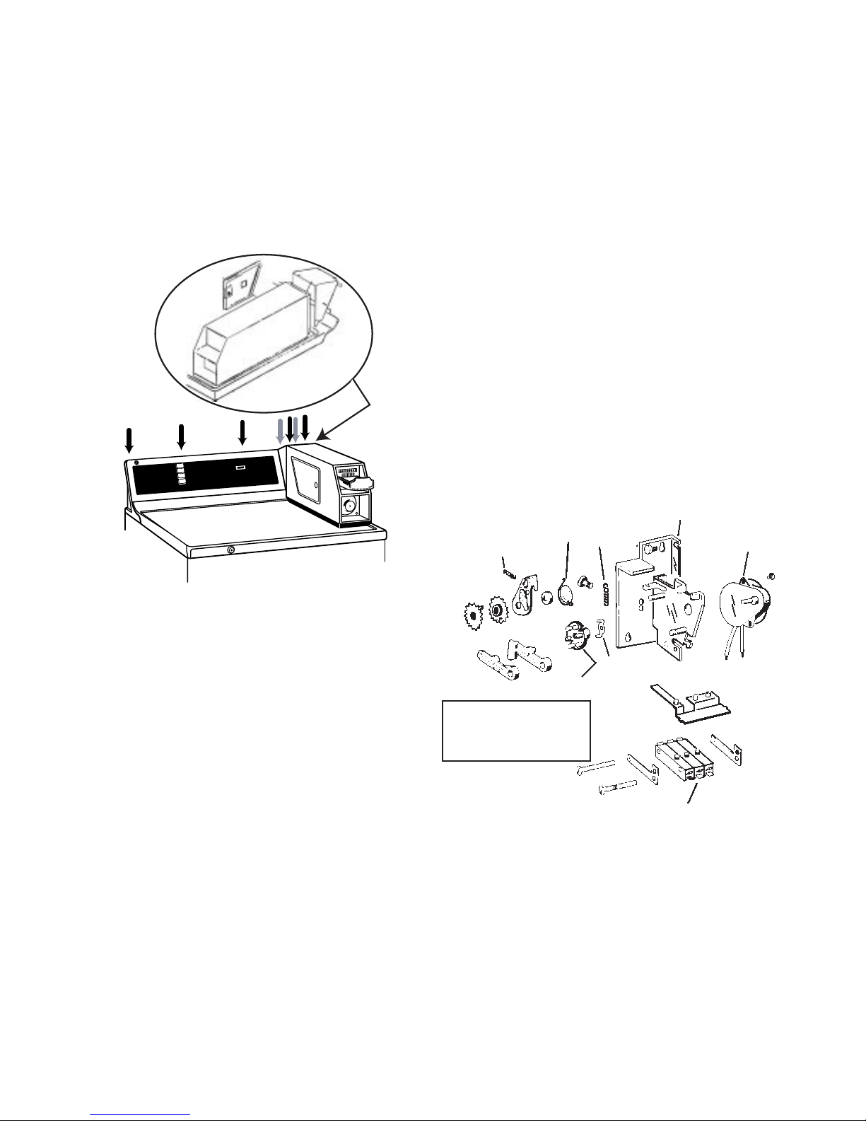
To access the dryer controls, disconnect power and
remove the four Phillips screws at the top of the
switch trim, remove the screws and the switch trim
adapter (shown in illustration below). Grasp the trim
at the top and pull forward. Three tabs at the bottom
fit into slots on the top panel.
Commerical Dryer
H
AS
T W
HEA
S
TTON
CO
ITH
T W
EA
H H
HIG
YCLE
N C
OL DOW
CO
RESS
T P
EN
AM
PERM
T
HEA
LOW
ITS
THETIC KN
SYN
T
E HEA
UM
RES
ART
TO ST
RESS
P
TING
PERA
O
.
dry time
oins for extra
dd c
A
.
1
r door is opened during
If drye
.
2
ART
T
S
S TO
ES
cycle, push PR
le.
e cyc
gain to resum
button a
Timer
The timer is an electromechanical control with a 115v
drive motor. On a timed cycle, the timer motor
receives 115 volts continuously for the number of
minutes selected for the cycle. The timer/
accumulator assembly consist of a mounting brac ket,
timing motor, snap s witch, timing cam, drive (timing
cams) coil spring(pawl), torsion spring (rachet asm),
amd coil spring (index lever). The timing motor is
115V-60HZ, and runs at 1/180 R.P.M. It is shipped
from the factory with a 45 minute cycle time. This
can be changed by ordering a different motor.
(specify voltage, frequency, and speed.) from
Greenwald Industries. See sample par ts catalog
pages for timer section for full address.
Timer/Accumulator
Torsion Spring
(Ratchet Asm)
Coil Spring
(pawl)
Coil
Spring
(IndexLever)
Mounting
Bracket
Timing Motor
Temperature Selector Switch
The temperature selector switch, allows the
customer to select different temperature settings f or
drying. The switch contains a 3K ohm resistor on
the electric model and a 2.4K ohm resistor on the
gas model. On the “Medium” setting, the selector
switch activates a control thermostat bias heater,
which is in series with the resistor on the switch. To
check the switch, disconnect power, remove the
wires from the switch and check f or continuity. With
the switch set on
“Regular” setting, there
should be continuity
only between terminals
1 and 2. On the
“Medium” setting, there
should be continuity
only between terminals
3 and 4. On a “Fluff ”
setting, there should be no continuity between either
set of terminals.
Timing Cam
Greenwald Industries, Inc.
1340 Metropolitan AVe.,
Brooklyn, N.Y 11237
Phone 1-800-221-0982
Drive
(Timing Cams)
Enclosed Snap
Switch
11
Page 13
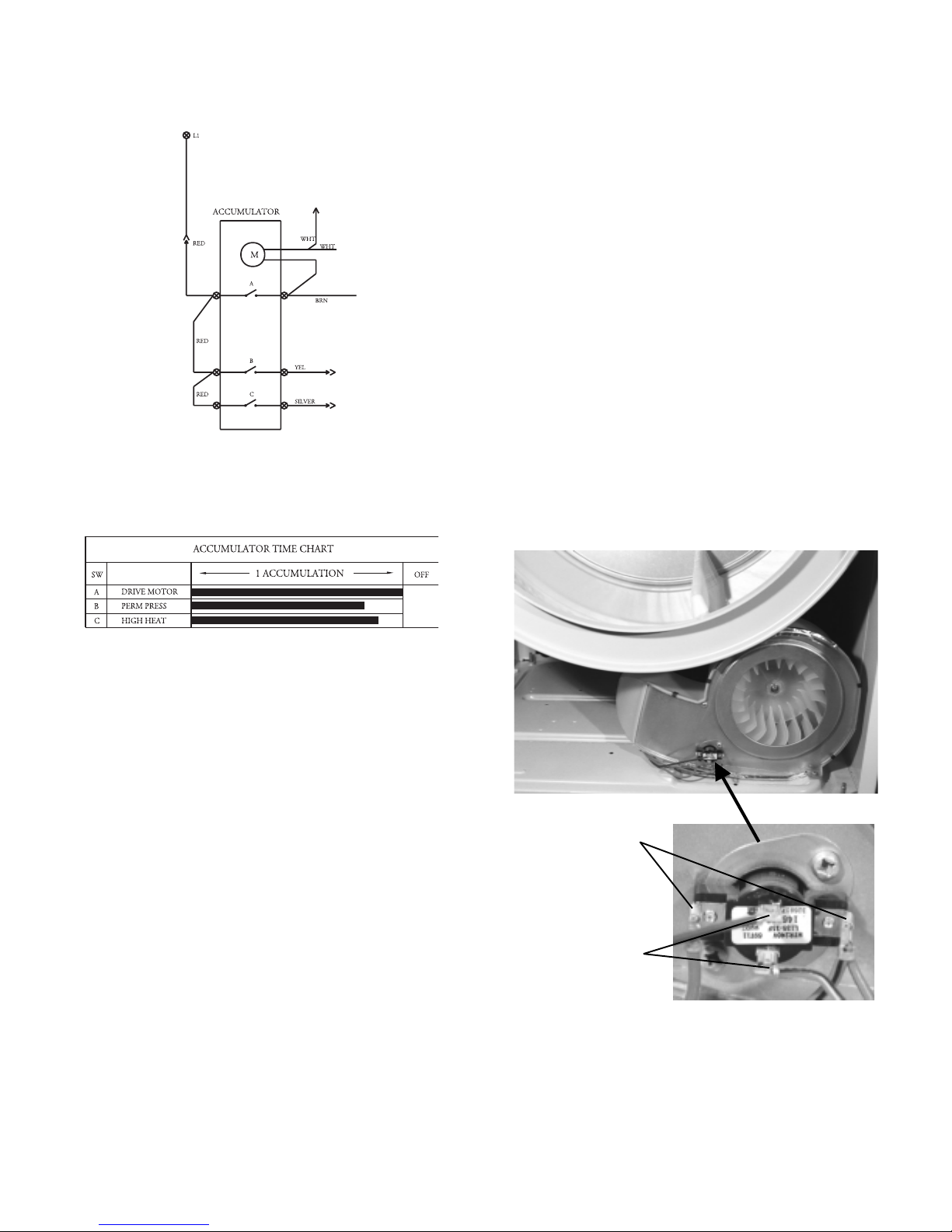
Schematic Detail of Timer/Accumulator
Door Switch
The door switch is a normally open switch wired in
series with the drive motor. When the door is closed
and the motor running, a circuit is completed through
the motor’s run winding. To test the switch, remove
the top panel and wires from the switch. When the
door is closed, the switch should read continuity.
When the door is open, the switch should read open.
To replace the switch, squeeze the retaining clips
together and pull the switch from the front of the
dryer.
Control Thermostat and Bias Heater
The control thermostat regulates the temperature
inside the dryer drum. It is a single pole, single throw
switch wired in series with the high limit (or safety)
thermostat and the heat source. It is mounted on
the front of the blower housing. The control
thermostat also contains a bias heater. The purpose
of the bias heater is to apply a small amount of heat
to the control thermostat when the fabric selector
switch is set to the medium temperature setting. This
small amount of heat causes the thermostat to open
sooner to maintain a lower drum temperature.
Timer/Accumulator Bar Chart
T o diagnose the timer/accumulator , use the bar chart
located on the mini manual behind the switch trim.
Rotate the timer to a point in the particular cycle
you want to check. Find the appropriate location
the timer pointer is set in the cycles across the first
column. Read ver tically down the chart from that
point. At each point you cross a shaded row, the
contacts listed at the left on the same row should
have continuity. Note the shaded areas are
proportional to the total time, so take several
continuity measurements at different points within
the cycle before determining the timer motor needs
replacement. As you can see from the e xample of a
gas dryer above, the contacts are made most of the
cycle.
THERMOSTAT
TERMINALS
BIAS HEA TER
TERMINALS
NOTE:
The control thermostats are not interchangeable
between an electric and a gas dryer. The resistance
of the bias heater is 28K ohms on the electric dryer
and 7K ohms on the gas dryer.
12
Page 14

To check the control thermostat, remove the wiring
from the terminals. At room temperature, the
thermostat should have continuity between the
control thermostat terminals. To check the bias
heater, remove the wiring from the bias heater
terminals. Check the resistance between the bias
heater terminals. On an electric dryer, the resistance
should be 28K ohms. On a gas dryer, the resistance
should be 7K ohms.
To check for correct dryer temperatures, make
certain all panels are in place on the dryer and
remove the e xhaust venting from the rear of the dryer.
Place a thermometer capable of reading at least
300°F in the end of the dryer duct. Set the timer
and allow the dryer to operate for 10 minutes with
an empty drum. Check the temper ature immediately
after the thermostat has cycled off and the dryer
has reached its highest temperature. Depending
upon the cycle selected, the temperatures should
be between 165°F-195°F on a “High” setting and
between 150°F-180°F for a “Medium” setting. If the
complaint is long drying times and the temperatures
are correct, check for a restricted vent, too long a
vent run, or an excessiv e number of turns in the vent.
High Limit (Safety) Thermostat
The high limit (safety) thermostat is a single pole,
single throw switch wired in series with the control
thermostat. It is mounted towards the top of the
heater pan shield at the rear of the drum. If the
control thermostat should fail closed or an air
blockage occurs, raising the temperature in the
heater pan, the high limit thermostat opens the circuit
to the heat source.
THERMAL
LIMITER
HIGH LIMIT
SAFETY
THERMOSTAT
Thermal Limiter
The thermal limiter is wired in series with the drive
motor on all electric dryers. The purpose of the
thermal limiter is to shut down the dryer should the
control thermostat and the high limit thermostat fail
to open. Once the ther mal limiter has opened, it
must be replaced. In addition, the condition that
caused it to open must be corrected. The most lik ely
cause would be a restriction in the dryer vent, an
excessively long v ent or a vent with excessiv e turns.
This is especially true if vinyl or plastic venting was
used.
Heat System (Electric Dryers)
The heater assembly is located behind the dryer
drum. Holes in the back of the drum allow heated
air to be drawn into the drum. The heating element
is an open coil heater, attached to a metal shroud
HIGH LIMIT
SAFETY
THERMOSTAT
HEATER
TERMINALS
13
Page 15

by removing the drum and visually inspecting the
element for breaks. Remove the leads from the
heater terminals and check for 12 ohms across the
terminals, then check each terminal to ground. If
the element is open or grounded, replace the heating
assembly. To replace the heater assembly, remove
the four Phillips screws holding the assemb ly to the
cabinet back. Transfer the high limit (safety)
thermostat from the old heater shroud to the new
shroud and install the new assembly.
Heat System (Gas models)
Belt Switch
The belt switch is a normally closed switch and is
mounted on the motor bracket ne xt to the idler arm.
If the drive belt breaks or jumps off the idler pulley,
the idler arm will contact the belt switch, causing the
switch contacts to open, and thereby opening the
circuit to the motor. T o access the belt switch, remo ve
the access panel on the rear of the dryer. Remove
the leads from the switch and connect an ohmmeter
across the switch terminals. The ohmmeter should
read continuity when the belt is on.
The heating system for a gas dryer is comprised of
three main components, the ignitor, the flame sensor
switch, and the gas control valve.
The ignitor is a silicon carbide thermistor mounted
at an angle with the tip extending into the flame area.
Depending on room temperature, the resistance of
the ignitor should be between 50 to 400 ohms. The
ignitor is fragile and susceptible to contamination
from skin oils. Use only the ignitor’s insulated support
when handling to prevent damage . Electrically, the
ignitor is in parallel with the booster coil. The parallel
circuit of the ignitor and booster coil is in series with
the secondary coil on the gas valve. The series –
parallel circuit of the ignitor, booster coil, and
secondary coil is in tur n in parallel with the holding
coil on the gas valve. Note: During the auto dry
cycle, you will be able to read some voltage at the
ignitor whenever the dryer is operating.
The flame sensor switch mounts on the side of the
burner duct and is single pole, single throw switch.
When the ignitor reaches approximately 1800°, the
flame sensor switch detects this high radiant heat
and opens. This energizes the secondary solenoid
gas valve coil, allowing gas to flow through the gas
valve . Gas flowing into the b urner duct is ignited by
the still hot ignitor. The flame within the b urner duct
heats the air being drawn into the back of the drum.
IGNITOR
BURNER ASSEMBLY
CENTRIFUGAL SWITCH
BELT
SWITCH
Motor
The drive motor is a single speed, dual shaft, ¼ hp,
1725 rpm motor with an automatic reset overload
protector. The overload protector in an internal
component of the motor and cannot be replaced
separately. The motor shaft is threaded on one end
for the blo wer wheel, with the belt pulley on the other.
The pulley is not available separately and comes
pressed on the shaft of a new motor.
FLAME SENSOR
GAS V AL VE
14
Page 16

The motor contains a centrifugal switch which serves
three purposes: It disengages the motor start
winding, engages the motor run winding and closes
the circuit for the heat source. When the motor is
off, the switch completes a circuit from M5 through
the motor start winding to M4. The contact M1 to
M2 is open. Immediately as the motor is started,
centrifugal force pulls the switch activating collar in
on the motor. This opens the circuit through the
start winding and completes the circuit M6 through
the run winding to M4. The contacts M1 to M2 close
to activate the heat source.
MOTOR OFF
tape, two Phillips screws and the six clips holding
the cover in place. Note the retaining clips under
the aluminum tape at the bottom edge of the cover.
When reassembling, make certain the cover is
sealed to the housing with aluminum tape. If the
original tape cannot be reused, use aluminum tape
WD49X27 to seal the cover.
Unscrew the blower wheel in a clockwise direction
from the motor shaft using a 7/8” sock et on the blower
wheel and holding the motor shaft by the pulley. The
clockwise direction is marked on the center of the
wheel.
MOTOR RUNNING
T o chec k the switch, disconnect the dryer from power
and remove the drum. If the motor starts to run and
stops when the start switch is released, place an
ohm meter across terminals M5 and M6 and
manually pull in on the collar to activate the switch.
You should read continuity. If the motor runs and
there is no heat, activate the switch and check
between M1 and M2. You should read continuity.
Motor Removal
T o replace the motor , disconnect power , remov e the
top and front panels, belt and dryer drum. Remov e
the fan cover by carefully removing the aluminum
Direction
of removal
marked on
the blower
wheel
7/8”
hex nut
Once the blower wheel is unscrewed, remove the
motor mounting clip and unplug the wiring harness
from the motor.
MOTOR
MOUNTING
CLIP
WIRING HARNESS
F AN COVER
15
Page 17

Next, remove the fan housing lock from the rear of
the blower housing.
FAN
HOUSING
LOCK
To remove the lock, insert a flat bade screwdriver
as shown below . Pry the lock away from the housing
far enough to clear the retaining tab and lift the lock
out of the channel.
MOTOR AND HARNESS WIRING
(Motor remove for clarity in illustrations)
FAN
HOUSING
LOCK
RETAINING
TAB
Once the lock is removed, the motor can be pulled
from the blower housing.
16
Page 18

Ω
Ω
17
Page 19

18
Page 20

Dryer Will Not Run
Service fuse,
breaker, outlet
problem
Repair terminal
block connection.
Replace door
switch
Replace start
switch
Electric Dryer
N
N
N
N
Adequate voltage
to dryer?
Y
Connections at
terminal block
OK?
Y
Door switch
contacts closed?
Y
Start switch
contacts closed?
Y
Service fuse,
breaker, outlet
problem
Replace door
switch
Replace start
switch
Replace timer
in coinbox
(Greenwald)
Gas Dryer
N
N
N
N
Adequate voltage
to dryer?
Y
Door switch
contacts closed?
Y
Start switch
contacts closing?
Y
Timer contacts
B & C closed?
Y
Replace timer
Replace thermal
limiter and
correct failure
fault
Replace belt
switch
Replace motor
N
N
N
N
Timer contacts
B & C closed?
Y
Contacts on
thermal limiter
closed?
Y
Belt switch
contacts closed?
Y
Check motor
centrifugal switch
reading between
contacts 4 & 5:
Or
Using a properly
grounded test
cord connected to
terminals 4 & 5
does the motor
run?
Y
Replace belt
switch
Replace motor
N
N
Belt switch
contacts closed?
Y
Check motor
centrifugal switch
reading between
contacts 4 & 5:
Or
Using a properly
grounded test
cord connected to
terminals 4 & 5
does the motor
run?
Y
Open wiring
between
components.
Locate and repair.
components.
Locate and repair
Open wiring
between
19
Page 21

No Heat - Drum Turns
Electric Dryer
Service fuse,
breaker, wall
outlet problem
Replace power
cord
Replace timer
Greenwald
Replace
temperature
selector switch
Replace control
thermostat
N
N
N
N
N
Adequate voltage
to dryer at outlet?
Y
Correct voltage at
dryer terminal
block?
Y
Turn timer on
Contacts A & B
closed on the
timer?
Y
Contacts 1 & 2
closed on the
temperature
selector switch?
Y
Contacts on the
control thermostat
closed?
Not applicable
on all models
Replace hi limit
thermostat
Replace heater
Replace
motor
N
N
N
Open wiring
between
components.
Locate and repair
Y
Contacts on high
limit thermostat
closed?
Y
Heater resistance
OK?
Y
Continuity
between contacts
1 & 2 on
centrifugal
switch? Manually
move the switch
to run position to
check these
contacts
Y
20
Page 22

No Heat - Drum Turns
Gas Dryer
Ignitor glowing?
N Y
Replace flame
sensor
Replace timer N
Greenwald
Replace
temperature
selector switch
Replace control
thermostat
Replace high limit
thermostat
N
contacts closed?
Contacts A & B
Contacts 1 & 2
N
selector switch?
Contacts on the
N
control thermostat
Contacts on the
N
Flame sensor
Y
closed on the
timer?
Y
closed on the
temperature
Y
closed?
Y
high limit
thermostat
closed?
Fix supply
problem
Ignitor between
50 and 400 ohms
at room
temperature?
Y
Flame sensor
contacts open
after ignitor has
been on 15 to 90
seconds max.?
Y
Gas valve
solenoids check
OK?
Y
120 volts to gas
valve solenoids?
N
Y
N
N
N
N
Gas supply OK
to dryer?
Replace ignitor
Replace flame
sensor
Replace gas
valve assembly
Open wiring in
gas valve circuit,
locate and repair
Replace
motor
Open wiring to
one of the
components.
Locate and repair.
N
Continuity
between contact
1 and 2 on the
centrifugal
switch?
Manuall move the
switch to the run
position to check
the contacts.
Y
Y
Y
Replace gas
valve assembly
Not applicable
on all models
21
Page 23

For complete Illustrated
Parts Catalog information
consult your GE Parts
Catalog, or Microfiche.
These examples are for
illustration purposes only.
22
Page 24

23
Page 25

24
Page 26

25
Page 27

26
Page 28

27
Page 29

28
Page 30

29
Page 31

30
Page 32

31
Page 33

32
Page 34

33
Page 35

34
Page 36

35
Page 37

36
Page 38

37
Page 39

38
Page 40

39
Page 41

40
Page 42

41
 Loading...