

Page 1

Dash® 3000/4000
Patient Monitor
Operator’s Manual
Software Version 4
2000966-171 Revision B
g
GE Medical Systems
Information Technologies
gemedicalsystem.com
Page 2

127(The information in this manual only applies to Dash 3000/4000
patient monitor software version 4. Due to continuing product
innovation, specifications in this manual are subject to change without
notice.
Listed below are GE Medical Sy stems Information Technolog ies’ trademarks used in this document. All other
trademarks contained herein are the property of their respective owners.
DASH, EAGLE, MULTI-LINK, MUSE, SAM, SOLAR, TRIM KNOB, and UNITY NETWORK are trademarks
of GE Medical Systems Information Technologies registered in the United States Patent and Trademark
Office.
12SL, CENTRALSCOPE, and MENTOR are trademarks of GE Medical Systems Information Technologies.
© GE Medical Systems Information Technologies, 2002. All rights reserved.
T-2 Dash 3000/4000 Patient Monitor Revision B
2000966-171 7 August 2002
Page 3

CE Marking Information
0459
CE Marking Information
Compliance
The Dash 3000/4000 patient monitor bears CE mark CE-0459 indicating
its conformity with the provisions of the Council Directive 93/42/EEC
concerning medical devices and fulfills the essential requirements of
Annex I of this directive. The product is in radio-interference protection
class A in accordance with EN 55011.
The country of manufacture can be found on the equipment labeling.
The product complies with the requirements of standard EN 60601-1-2
“Electromagnetic Compatibility - Medical Electrical Equipment”.
The safety and effecti veness of this device has been ve rified against
previously distributed devices. Although all standards applicable to
presently marketed devices may not be appropriate for prior devices (i.e.
electromagnetic compatibility standards), this device will not impair the
safe and effective use of those previously distributed devices. See user’s
information.
Electromagnetic Compatibility
Electromagnetic compatibility (EMC) information can be found in the
appendices chapter of this manual.
Radio and Telecommunication Terminal Equipment Directive
The monitor contains a transmitter. The transmitter bears a CE mark
indicating conformity with the essential requirements specified in Article
3 of the Council Directive 1999/5/EC of 9 March 1999 concerning Radio
Equipment and Telecommunications Terminal Equipment (R&TTE).
The essential requirements are as follows:
Article 3.1 (a) Health Safety; the product complies with the particular
medical device safety standards specified in the Medical Device Directive
93/42/EEC:
1. EN 60601-1 Medical electrical equipment: Part 1: General
requirements for safety - IEC 601-1:1988.
2. Amendment A1 to EN 60 601-1 Medical electrical equipment: Part 1:
General requirements for safety - IEC 601-1:1998A1”1991.
3. Amendment A2 to EN 60 601-1 Medical electrical equipment: Part 1:
General requirements for safety - IEC 601-1:1998/A2:1995 +
corrigendum June 1995.
Article 3.1 (b) EMC; the product complies with:
Revision B Dash 3000/4000 Patient Monitor CE-1
2000966-171
Page 4

General Information
CE Marking Information
1. EN 60601-1-2 Medical electrical equipment: Part 1: General
requirements for safety - 2. Collateral standard: Electromagnetic
compatibility - requirements and test - IEC 601-1-2:1993.
2. EN 300 826: “Electromagnetic compatibility and Radio spectrum
Matters (ERM); ElectroMagnetic Compatibility (EMC) standard for
2.4 GHz wideband transmission systems and HIgh PErformance
Radio Local Area Network (HIPERLAN) equipment”.
Article 3.2 Protection of the Radio Spectrum: the product complies with:
n
EN 300 328: “Radio Equipment and Systems (RES); Wideband
transmission systems; Technical characteristics and test conditions
for data transmission equi pment operat in g in t he 2.4 GHz IS M ba nd
and using spread spectrum modulation techniques”.
n
This manual is an integral part of the product and describes its
intended use. It should always be kept close to the equipment.
Observance of the manual is a prerequisite for proper product
performance and correct operation and ensures patient and operator
safety.
n
The symbol means ATTENTION: Consult accompanying
documents.
n
Information which refers only to certain versions of the product is
accompanied by the model number(s) of the product(s) concerned.
The model number is given on the nameplate of the product.
n
The warranty does not cover damages resulting from the use of
accessories and consumables from other manufacturers.
n
GE is responsible for the effects on safety, reliability, and
performance of the product, only if
n
assembly operations, extensions, readjustments, modifications,
or repairs are carried out by persons authorized by GE.
n
the electrical installation of the relevant room complies with the
requirements of the appropriate regulations; and,
n
the device is used in accordance with the instructions for use.
n
All publications are in conformity with the product specifications and
IEC publications on safety of electromedical equipment as well as
with UL and CSA requirements and AHA recommendations valid at
the time of printing.
n
The GE quality management system complies with the international
standards DIN/EN/ISO 9001 and EN 46001, and the Council
Directive on Medical Devices 93/42/EEC Annex II.
CE-2 Dash 3000/4000 Patient Monitor Revision B
2000966-171
Page 5

Contents
About This Manual . . . . . . . . . . . . . . . . . . . . . . . . . . . . . . . . . . . . . . . . . . . . . . . . . . . xiii
Manual Purpose . . . . . . . . . . . . . . . . . . . . . . . . . . . . . . . . . . . . . . . . . . . . . . . . . . . xiii
Intended Audience . . . . . . . . . . . . . . . . . . . . . . . . . . . . . . . . . . . . . . . . . . . . . . . . . xiii
Revision History . . . . . . . . . . . . . . . . . . . . . . . . . . . . . . . . . . . . . . . . . . . . . . . . . . . xiii
Manual Conventions . . . . . . . . . . . . . . . . . . . . . . . . . . . . . . . . . . . . . . . . . . . . . . . . . xiv
Product References . . . . . . . . . . . . . . . . . . . . . . . . . . . . . . . . . . . . . . . . . . . . . . . . xiv
Definitions . . . . . . . . . . . . . . . . . . . . . . . . . . . . . . . . . . . . . . . . . . . . . . . . . . . . . . . xiv
Illustrations and Names . . . . . . . . . . . . . . . . . . . . . . . . . . . . . . . . . . . . . . . . . . . . . xiv
Monitor Defaults Worksheet . . . . . . . . . . . . . . . . . . . . . . . . . . . . . . . . . . . . . . . . . . . . xv
1 The Basics . . . . . . . . . . . . . . . . . . . . . . . . . . . . . . . . . . . . . 1-1
Components . . . . . . . . . . . . . . . . . . . . . . . . . . . . . . . . . . . . . . . . . . . . . . . . . . . . . . . . 1-3
The Monitoring System . . . . . . . . . . . . . . . . . . . . . . . . . . . . . . . . . . . . . . . . . . . . .1-3
Dash 3000/4000 Monitor . . . . . . . . . . . . . . . . . . . . . . . . . . . . . . . . . . . . . . . . . . . .1-3
Optional RAC 2A Module Housing . . . . . . . . . . . . . . . . . . . . . . . . . . . . . . . . . . . . 1-6
SAM Module Information . . . . . . . . . . . . . . . . . . . . . . . . . . . . . . . . . . . . . . . . . . . 1-8
Optional Centralscope Central Station . . . . . . . . . . . . . . . . . . . . . . . . . . . . . . . . 1-10
Optional Clinical Information Center . . . . . . . . . . . . . . . . . . . . . . . . . . . . . . . . . 1-11
Optional Wireless LAN System . . . . . . . . . . . . . . . . . . . . . . . . . . . . . . . . . . . . . 1-12
Optional Laser Printer . . . . . . . . . . . . . . . . . . . . . . . . . . . . . . . . . . . . . . . . . . . . 1-15
Controls and Indicators . . . . . . . . . . . . . . . . . . . . . . . . . . . . . . . . . . . . . . . . . . . 1-16
Turning Power On . . . . . . . . . . . . . . . . . . . . . . . . . . . . . . . . . . . . . . . . . . . . . . . . . . 1-21
AC Power . . . . . . . . . . . . . . . . . . . . . . . . . . . . . . . . . . . . . . . . . . . . . . . . . . . . . . .1-21
Battery Power . . . . . . . . . . . . . . . . . . . . . . . . . . . . . . . . . . . . . . . . . . . . . . . . . . .1-21
Software Overview . . . . . . . . . . . . . . . . . . . . . . . . . . . . . . . . . . . . . . . . . . . . . . . . . . 1-22
Software Packages and Software Options . . . . . . . . . . . . . . . . . . . . . . . . . . . . .1-22
Monitor Display . . . . . . . . . . . . . . . . . . . . . . . . . . . . . . . . . . . . . . . . . . . . . . . . . 1-24
Menus . . . . . . . . . . . . . . . . . . . . . . . . . . . . . . . . . . . . . . . . . . . . . . . . . . . . . . . . .1-24
Popup Menus . . . . . . . . . . . . . . . . . . . . . . . . . . . . . . . . . . . . . . . . . . . . . . . . . . . 1-27
Subordinate Menus . . . . . . . . . . . . . . . . . . . . . . . . . . . . . . . . . . . . . . . . . . . . . . .1-28
Direct Action Menu Options . . . . . . . . . . . . . . . . . . . . . . . . . . . . . . . . . . . . . . . . 1-29
Parameter Windows . . . . . . . . . . . . . . . . . . . . . . . . . . . . . . . . . . . . . . . . . . . . . . 1-30
Information Windows . . . . . . . . . . . . . . . . . . . . . . . . . . . . . . . . . . . . . . . . . . . . . .1-31
Trim Knob Control Operation When Setting Alarm Limits . . . . . . . . . . . . . . . . . .1-32
Graphing (Printing) . . . . . . . . . . . . . . . . . . . . . . . . . . . . . . . . . . . . . . . . . . . . . . . . . 1-33
Devices . . . . . . . . . . . . . . . . . . . . . . . . . . . . . . . . . . . . . . . . . . . . . . . . . . . . . . . .1-33
Manual Graphs . . . . . . . . . . . . . . . . . . . . . . . . . . . . . . . . . . . . . . . . . . . . . . . . . .1-33
Pressure Scales . . . . . . . . . . . . . . . . . . . . . . . . . . . . . . . . . . . . . . . . . . . . . . . . . .1-34
Graphing Messages . . . . . . . . . . . . . . . . . . . . . . . . . . . . . . . . . . . . . . . . . . . . . . 1-35
Revision B Dash 3000/4000 Patient Monitor i
2000966-171
Page 6

Graph Header . . . . . . . . . . . . . . . . . . . . . . . . . . . . . . . . . . . . . . . . . . . . . . . . . . .1-35
Putting the Monitor Into Operation . . . . . . . . . . . . . . . . . . . . . . . . . . . . . . . . . . . . 1-36
Monitor Installation and Connection . . . . . . . . . . . . . . . . . . . . . . . . . . . . . . . . . . .1-36
Performance Check . . . . . . . . . . . . . . . . . . . . . . . . . . . . . . . . . . . . . . . . . . . . . . .1-37
Language-Specific Information . . . . . . . . . . . . . . . . . . . . . . . . . . . . . . . . . . . . . . . 1-38
French Language Information . . . . . . . . . . . . . . . . . . . . . . . . . . . . . . . . . . . . . . .1-38
Hungarian, Polish, and Russian, Language Information . . . . . . . . . . . . . . . . . . .1-38
Chinese and Japanese Language Information . . . . . . . . . . . . . . . . . . . . . . . . . .1-38
2 Safety . . . . . . . . . . . . . . . . . . . . . . . . . . . . . . . . . . . . . . . . . 2-1
For Your Safety . . . . . . . . . . . . . . . . . . . . . . . . . . . . . . . . . . . . . . . . . . . . . . . . . . . . . 2-3
Intended Use . . . . . . . . . . . . . . . . . . . . . . . . . . . . . . . . . . . . . . . . . . . . . . . . . . . . .2-3
Terminology . . . . . . . . . . . . . . . . . . . . . . . . . . . . . . . . . . . . . . . . . . . . . . . . . . . . . .2-3
Monitor Safety . . . . . . . . . . . . . . . . . . . . . . . . . . . . . . . . . . . . . . . . . . . . . . . . . . . .2-3
Reference Literature . . . . . . . . . . . . . . . . . . . . . . . . . . . . . . . . . . . . . . . . . . . . . .2-11
Classifications . . . . . . . . . . . . . . . . . . . . . . . . . . . . . . . . . . . . . . . . . . . . . . . . . . . . . 2-12
Underwriters Laboratories, Inc. . . . . . . . . . . . . . . . . . . . . . . . . . . . . . . . . . . . . . .2-12
Equipment Symbols . . . . . . . . . . . . . . . . . . . . . . . . . . . . . . . . . . . . . . . . . . . . . . 2-13
3 Admit Discharge . . . . . . . . . . . . . . . . . . . . . . . . . . . . . . . . 3-1
About Admitting . . . . . . . . . . . . . . . . . . . . . . . . . . . . . . . . . . . . . . . . . . . . . . . . . . . . . 3-3
You Must Admit to Activate Alarms . . . . . . . . . . . . . . . . . . . . . . . . . . . . . . . . . . . .3-3
Monitors are Used in Different Ways . . . . . . . . . . . . . . . . . . . . . . . . . . . . . . . . . . .3-3
For Which Application is the Monitor Set? . . . . . . . . . . . . . . . . . . . . . . . . . . . . . . .3-4
Getting to the Admit Menu . . . . . . . . . . . . . . . . . . . . . . . . . . . . . . . . . . . . . . . . . . . . 3-5
Standard Admit Menu . . . . . . . . . . . . . . . . . . . . . . . . . . . . . . . . . . . . . . . . . . . . . . . . 3-6
Rover Admit Menu . . . . . . . . . . . . . . . . . . . . . . . . . . . . . . . . . . . . . . . . . . . . . . . . . . . 3-7
Combo Admit Menu . . . . . . . . . . . . . . . . . . . . . . . . . . . . . . . . . . . . . . . . . . . . . . . . . . 3-8
Rover Combo Admit Menu . . . . . . . . . . . . . . . . . . . . . . . . . . . . . . . . . . . . . . . . . . . . 3-9
Admit Menu Options . . . . . . . . . . . . . . . . . . . . . . . . . . . . . . . . . . . . . . . . . . . . . . . . 3-11
Change Admit Info . . . . . . . . . . . . . . . . . . . . . . . . . . . . . . . . . . . . . . . . . . . . . . . .3-11
Request Admit Info . . . . . . . . . . . . . . . . . . . . . . . . . . . . . . . . . . . . . . . . . . . . . . 3-13
Recall Default . . . . . . . . . . . . . . . . . . . . . . . . . . . . . . . . . . . . . . . . . . . . . . . . . . . .3-13
Admit Help . . . . . . . . . . . . . . . . . . . . . . . . . . . . . . . . . . . . . . . . . . . . . . . . . . . . . 3-14
Admit Patient . . . . . . . . . . . . . . . . . . . . . . . . . . . . . . . . . . . . . . . . . . . . . . . . . . . .3-14
Units of Measure . . . . . . . . . . . . . . . . . . . . . . . . . . . . . . . . . . . . . . . . . . . . . . . . .3-15
ii Dash 3000/4000 Patient Monitor Revision B
2000966-171
Page 7

Set Unit Name . . . . . . . . . . . . . . . . . . . . . . . . . . . . . . . . . . . . . . . . . . . . . . . . . . 3-16
Set Bed Number . . . . . . . . . . . . . . . . . . . . . . . . . . . . . . . . . . . . . . . . . . . . . . . . .3-17
Graph Location . . . . . . . . . . . . . . . . . . . . . . . . . . . . . . . . . . . . . . . . . . . . . . . . . .3-17
ECG Source . . . . . . . . . . . . . . . . . . . . . . . . . . . . . . . . . . . . . . . . . . . . . . . . . . . . .3-18
About Discharging . . . . . . . . . . . . . . . . . . . . . . . . . . . . . . . . . . . . . . . . . . . . . . . . . . 3-19
Discharge Patient . . . . . . . . . . . . . . . . . . . . . . . . . . . . . . . . . . . . . . . . . . . . . . . . .3-19
4 Alarm Control . . . . . . . . . . . . . . . . . . . . . . . . . . . . . . . . . . 4-1
Smart Alarms . . . . . . . . . . . . . . . . . . . . . . . . . . . . . . . . . . . . . . . . . . . . . . . . . . . . . . . 4-3
Alarm Structure . . . . . . . . . . . . . . . . . . . . . . . . . . . . . . . . . . . . . . . . . . . . . . . . . . . . . 4-4
Patient Status Alarms . . . . . . . . . . . . . . . . . . . . . . . . . . . . . . . . . . . . . . . . . . . . . .4-4
System Status Alarms . . . . . . . . . . . . . . . . . . . . . . . . . . . . . . . . . . . . . . . . . . . . . .4-5
On-Screen Alarm Help . . . . . . . . . . . . . . . . . . . . . . . . . . . . . . . . . . . . . . . . . . . . . .4-5
Controlling Audio Alarms . . . . . . . . . . . . . . . . . . . . . . . . . . . . . . . . . . . . . . . . . . . . . 4-6
Silencing an Alarm for One Minute . . . . . . . . . . . . . . . . . . . . . . . . . . . . . . . . . . . .4-6
Pausing Alarms . . . . . . . . . . . . . . . . . . . . . . . . . . . . . . . . . . . . . . . . . . . . . . . . . . .4-6
Alarm Pause Breakthrough . . . . . . . . . . . . . . . . . . . . . . . . . . . . . . . . . . . . . . . . . .4-7
Turning Alarm Volume Off Permanently . . . . . . . . . . . . . . . . . . . . . . . . . . . . . . . .4-7
Alarm Window . . . . . . . . . . . . . . . . . . . . . . . . . . . . . . . . . . . . . . . . . . . . . . . . . . . . . . 4-8
Clear Alarms . . . . . . . . . . . . . . . . . . . . . . . . . . . . . . . . . . . . . . . . . . . . . . . . . . . . .4-8
Alarm History . . . . . . . . . . . . . . . . . . . . . . . . . . . . . . . . . . . . . . . . . . . . . . . . . . . . .4-8
Alarm Control Menu . . . . . . . . . . . . . . . . . . . . . . . . . . . . . . . . . . . . . . . . . . . . . . . . . . 4-9
All Limits . . . . . . . . . . . . . . . . . . . . . . . . . . . . . . . . . . . . . . . . . . . . . . . . . . . . . . . . .4-9
Arrhythmia Alarm Level . . . . . . . . . . . . . . . . . . . . . . . . . . . . . . . . . . . . . . . . . . . 4-12
Parameter Alarm Level . . . . . . . . . . . . . . . . . . . . . . . . . . . . . . . . . . . . . . . . . . . 4-14
Alarm Help . . . . . . . . . . . . . . . . . . . . . . . . . . . . . . . . . . . . . . . . . . . . . . . . . . . . . 4-16
Display Off Alarm Pause . . . . . . . . . . . . . . . . . . . . . . . . . . . . . . . . . . . . . . . . . . 4-17
Clear Alarms . . . . . . . . . . . . . . . . . . . . . . . . . . . . . . . . . . . . . . . . . . . . . . . . . . . .4-18
Alarm History . . . . . . . . . . . . . . . . . . . . . . . . . . . . . . . . . . . . . . . . . . . . . . . . . . . 4-19
5 Monitor Setup . . . . . . . . . . . . . . . . . . . . . . . . . . . . . . . . . . 5-1
Monitor Setup Menu . . . . . . . . . . . . . . . . . . . . . . . . . . . . . . . . . . . . . . . . . . . . . . . . . 5-3
Waveforms On / Off . . . . . . . . . . . . . . . . . . . . . . . . . . . . . . . . . . . . . . . . . . . . . . . 5-4
Display . . . . . . . . . . . . . . . . . . . . . . . . . . . . . . . . . . . . . . . . . . . . . . . . . . . . . . . . . 5-6
Color . . . . . . . . . . . . . . . . . . . . . . . . . . . . . . . . . . . . . . . . . . . . . . . . . . . . . . . . . . 5-7
Parameters On / Off . . . . . . . . . . . . . . . . . . . . . . . . . . . . . . . . . . . . . . . . . . . . . . . 5-8
Graph Setup . . . . . . . . . . . . . . . . . . . . . . . . . . . . . . . . . . . . . . . . . . . . . . . . . . . . . 5-9
Monitor Defaults . . . . . . . . . . . . . . . . . . . . . . . . . . . . . . . . . . . . . . . . . . . . . . . . . 5-15
Monitor Defaults Menu . . . . . . . . . . . . . . . . . . . . . . . . . . . . . . . . . . . . . . . . . . . . 5-16
Monitor Default Password . . . . . . . . . . . . . . . . . . . . . . . . . . . . . . . . . . . . . . . . . .5-27
Revision B Dash 3000/4000 Patient Monitor iii
2000966-171
Page 8

Brightness . . . . . . . . . . . . . . . . . . . . . . . . . . . . . . . . . . . . . . . . . . . . . . . . . . . . . .5-28
Learn the Monitor . . . . . . . . . . . . . . . . . . . . . . . . . . . . . . . . . . . . . . . . . . . . . . . . .5-29
Software Configuration . . . . . . . . . . . . . . . . . . . . . . . . . . . . . . . . . . . . . . . . . . . 5-30
Revision and ID . . . . . . . . . . . . . . . . . . . . . . . . . . . . . . . . . . . . . . . . . . . . . . . . . 5-31
Service Mode . . . . . . . . . . . . . . . . . . . . . . . . . . . . . . . . . . . . . . . . . . . . . . . . . . . 5-32
6 CRG Trends Display . . . . . . . . . . . . . . . . . . . . . . . . . . . . . 6-1
CRG Trends . . . . . . . . . . . . . . . . . . . . . . . . . . . . . . . . . . . . . . . . . . . . . . . . . . . . . . . . 6-3
CRG Trends Display . . . . . . . . . . . . . . . . . . . . . . . . . . . . . . . . . . . . . . . . . . . . . . .6-3
CRG Trends Event Directory . . . . . . . . . . . . . . . . . . . . . . . . . . . . . . . . . . . . . . . . 6-4
CRG Trends Menu Options . . . . . . . . . . . . . . . . . . . . . . . . . . . . . . . . . . . . . . . . . .6-5
Document CRG Events . . . . . . . . . . . . . . . . . . . . . . . . . . . . . . . . . . . . . . . . . . . . . . . 6-7
Troubleshooting . . . . . . . . . . . . . . . . . . . . . . . . . . . . . . . . . . . . . . . . . . . . . . . . . . . . 6-8
7 View Other Patients . . . . . . . . . . . . . . . . . . . . . . . . . . . . . 7-1
Viewing Other Patients . . . . . . . . . . . . . . . . . . . . . . . . . . . . . . . . . . . . . . . . . . . . . . . 7-3
View Other Patients Menu . . . . . . . . . . . . . . . . . . . . . . . . . . . . . . . . . . . . . . . . . . . . . 7-5
View Alarm . . . . . . . . . . . . . . . . . . . . . . . . . . . . . . . . . . . . . . . . . . . . . . . . . . . . . . 7-6
View On Alarm Options . . . . . . . . . . . . . . . . . . . . . . . . . . . . . . . . . . . . . . . . . . . . .7-6
Select a Bed to View . . . . . . . . . . . . . . . . . . . . . . . . . . . . . . . . . . . . . . . . . . . . . . .7-9
Select Another Care Unit . . . . . . . . . . . . . . . . . . . . . . . . . . . . . . . . . . . . . . . . . . 7-10
Graph Viewed Bed . . . . . . . . . . . . . . . . . . . . . . . . . . . . . . . . . . . . . . . . . . . . . . . .7-10
8 Patient Data . . . . . . . . . . . . . . . . . . . . . . . . . . . . . . . . . . . . 8-1
Patient Data Menu . . . . . . . . . . . . . . . . . . . . . . . . . . . . . . . . . . . . . . . . . . . . . . . . . . . 8-3
Alarm History . . . . . . . . . . . . . . . . . . . . . . . . . . . . . . . . . . . . . . . . . . . . . . . . . . . . 8-4
Vital Signs . . . . . . . . . . . . . . . . . . . . . . . . . . . . . . . . . . . . . . . . . . . . . . . . . . . . . . 8-7
Graphic Trends . . . . . . . . . . . . . . . . . . . . . . . . . . . . . . . . . . . . . . . . . . . . . . . . . 8-10
Cardiac Calcs . . . . . . . . . . . . . . . . . . . . . . . . . . . . . . . . . . . . . . . . . . . . . . . . . . . .8-13
Pulmonary Calcs . . . . . . . . . . . . . . . . . . . . . . . . . . . . . . . . . . . . . . . . . . . . . . . . 8-17
Dose Calcs . . . . . . . . . . . . . . . . . . . . . . . . . . . . . . . . . . . . . . . . . . . . . . . . . . . . . 8-22
CRG Trends . . . . . . . . . . . . . . . . . . . . . . . . . . . . . . . . . . . . . . . . . . . . . . . . . . . . .8-31
Lab Data . . . . . . . . . . . . . . . . . . . . . . . . . . . . . . . . . . . . . . . . . . . . . . . . . . . . . . 8-32
iv Dash 3000/4000 Patient Monitor Revision B
2000966-171
Page 9

9 Batteries . . . . . . . . . . . . . . . . . . . . . . . . . . . . . . . . . . . . . . . 9-1
Battery Power . . . . . . . . . . . . . . . . . . . . . . . . . . . . . . . . . . . . . . . . . . . . . . . . . . . . . . . 9-3
Battery Run Time . . . . . . . . . . . . . . . . . . . . . . . . . . . . . . . . . . . . . . . . . . . . . . . . . 9-4
Battery Indicators . . . . . . . . . . . . . . . . . . . . . . . . . . . . . . . . . . . . . . . . . . . . . . . . . .9-4
Battery Packs . . . . . . . . . . . . . . . . . . . . . . . . . . . . . . . . . . . . . . . . . . . . . . . . . . . . . . . 9-6
Battery Charging . . . . . . . . . . . . . . . . . . . . . . . . . . . . . . . . . . . . . . . . . . . . . . . . . .9-6
Conditioning a Battery . . . . . . . . . . . . . . . . . . . . . . . . . . . . . . . . . . . . . . . . . . . . . 9-7
Battery Recycling . . . . . . . . . . . . . . . . . . . . . . . . . . . . . . . . . . . . . . . . . . . . . . . . . .9-7
Battery Status Menu . . . . . . . . . . . . . . . . . . . . . . . . . . . . . . . . . . . . . . . . . . . . . . . . . 9-8
Battery Help . . . . . . . . . . . . . . . . . . . . . . . . . . . . . . . . . . . . . . . . . . . . . . . . . . . . . 9-9
Battery Alarms . . . . . . . . . . . . . . . . . . . . . . . . . . . . . . . . . . . . . . . . . . . . . . . . . . . . . 9-10
10 Maintenance . . . . . . . . . . . . . . . . . . . . . . . . . . . . . . . . . . 10-1
Biocompatibility . . . . . . . . . . . . . . . . . . . . . . . . . . . . . . . . . . . . . . . . . . . . . . . . . . . . 10-3
Inspection . . . . . . . . . . . . . . . . . . . . . . . . . . . . . . . . . . . . . . . . . . . . . . . . . . . . . . . . . 10-4
General Cleaning . . . . . . . . . . . . . . . . . . . . . . . . . . . . . . . . . . . . . . . . . . . . . . . . . . . 10-5
Exterior Surface . . . . . . . . . . . . . . . . . . . . . . . . . . . . . . . . . . . . . . . . . . . . . . . . . .10-5
Display . . . . . . . . . . . . . . . . . . . . . . . . . . . . . . . . . . . . . . . . . . . . . . . . . . . . . . . . .10-5
Cleaning Applied Parts . . . . . . . . . . . . . . . . . . . . . . . . . . . . . . . . . . . . . . . . . . . . . . 10-6
Cables and Leadwires . . . . . . . . . . . . . . . . . . . . . . . . . . . . . . . . . . . . . . . . . . . . .10-6
Capnostat Sensor and Adapter . . . . . . . . . . . . . . . . . . . . . . . . . . . . . . . . . . . . . .10-6
Other . . . . . . . . . . . . . . . . . . . . . . . . . . . . . . . . . . . . . . . . . . . . . . . . . . . . . . . . . .10-6
Technical Maintenance . . . . . . . . . . . . . . . . . . . . . . . . . . . . . . . . . . . . . . . . . . . . . . 10-7
Technical Specifications . . . . . . . . . . . . . . . . . . . . . . . . . . . . . . . . . . . . . . . . . . . . . 10-7
Changing Graph Paper . . . . . . . . . . . . . . . . . . . . . . . . . . . . . . . . . . . . . . . . . . . . . . 10-8
Built-in Writer . . . . . . . . . . . . . . . . . . . . . . . . . . . . . . . . . . . . . . . . . . . . . . . . . . . .10-8
Thermal Paper Storage . . . . . . . . . . . . . . . . . . . . . . . . . . . . . . . . . . . . . . . . . . . . . . 10-9
Revision B Dash 3000/4000 Patient Monitor v
2000966-171
Page 10

11 ECG . . . . . . . . . . . . . . . . . . . . . . . . . . . . . . . . . . . . . . . . . 11-1
Introduction . . . . . . . . . . . . . . . . . . . . . . . . . . . . . . . . . . . . . . . . . . . . . . . . . . . . . . . 11-3
Turning the ECG Parameter Off or On . . . . . . . . . . . . . . . . . . . . . . . . . . . . . . . 11-4
Checklist . . . . . . . . . . . . . . . . . . . . . . . . . . . . . . . . . . . . . . . . . . . . . . . . . . . . . . 11-5
Skin Preparation . . . . . . . . . . . . . . . . . . . . . . . . . . . . . . . . . . . . . . . . . . . . . . . . . . . 11-6
Electrode Placement . . . . . . . . . . . . . . . . . . . . . . . . . . . . . . . . . . . . . . . . . . . . . . . . 11-7
5-Leadwire Electrode Placement . . . . . . . . . . . . . . . . . . . . . . . . . . . . . . . . . . . . .11-7
3-Leadwire Electrode Placement . . . . . . . . . . . . . . . . . . . . . . . . . . . . . . . . . . . . .11-8
Electrode Placement for Neonates . . . . . . . . . . . . . . . . . . . . . . . . . . . . . . . . . . .11-9
Electrode Placement for Pacemaker Patients . . . . . . . . . . . . . . . . . . . . . . . . . .11-10
10-Leadwire Electrode Configuration for 12SL Monitoring . . . . . . . . . . . . . . . .11-10
Maintaining Quality ECG Signal . . . . . . . . . . . . . . . . . . . . . . . . . . . . . . . . . . . . .11-12
Surgical Considerations for Electrode Placement (Adults) . . . . . . . . . . . . . . . .11-12
ESU ECG Filters . . . . . . . . . . . . . . . . . . . . . . . . . . . . . . . . . . . . . . . . . . . . . . . . . . . 11-13
Electrosurgical Unit (ESU) Cable . . . . . . . . . . . . . . . . . . . . . . . . . . . . . . . . . . . .11-13
ECG Monitoring Features . . . . . . . . . . . . . . . . . . . . . . . . . . . . . . . . . . . . . . . . . . . 11-14
ECG Display . . . . . . . . . . . . . . . . . . . . . . . . . . . . . . . . . . . . . . . . . . . . . . . . . . .11-14
Getting to the ECG Menu . . . . . . . . . . . . . . . . . . . . . . . . . . . . . . . . . . . . . . . . . .11-15
ECG Menu Options . . . . . . . . . . . . . . . . . . . . . . . . . . . . . . . . . . . . . . . . . . . . . . . . 11-17
Display Lead . . . . . . . . . . . . . . . . . . . . . . . . . . . . . . . . . . . . . . . . . . . . . . . . . . .11-17
ECG Size . . . . . . . . . . . . . . . . . . . . . . . . . . . . . . . . . . . . . . . . . . . . . . . . . . . . . 11-19
Detect Pace . . . . . . . . . . . . . . . . . . . . . . . . . . . . . . . . . . . . . . . . . . . . . . . . . . . 11-20
ECG Limits . . . . . . . . . . . . . . . . . . . . . . . . . . . . . . . . . . . . . . . . . . . . . . . . . . . . 11-24
View All ECG . . . . . . . . . . . . . . . . . . . . . . . . . . . . . . . . . . . . . . . . . . . . . . . . . . .11-26
Clear V2-V6 Fail . . . . . . . . . . . . . . . . . . . . . . . . . . . . . . . . . . . . . . . . . . . . . . . . .11-26
Arrhythmia . . . . . . . . . . . . . . . . . . . . . . . . . . . . . . . . . . . . . . . . . . . . . . . . . . . . 11-27
Relearn . . . . . . . . . . . . . . . . . . . . . . . . . . . . . . . . . . . . . . . . . . . . . . . . . . . . . . .11-30
ST Analysis . . . . . . . . . . . . . . . . . . . . . . . . . . . . . . . . . . . . . . . . . . . . . . . . . . . 11-31
Turn ST On and Off . . . . . . . . . . . . . . . . . . . . . . . . . . . . . . . . . . . . . . . . . . . . . .11-33
ST Analysis Menu . . . . . . . . . . . . . . . . . . . . . . . . . . . . . . . . . . . . . . . . . . . . . . .11-34
ECG Filter . . . . . . . . . . . . . . . . . . . . . . . . . . . . . . . . . . . . . . . . . . . . . . . . . . . . 11-41
12 Lead ECG Analysis . . . . . . . . . . . . . . . . . . . . . . . . . . . . . . . . . . . . . . . . . . . 11-42
Lead Analysis . . . . . . . . . . . . . . . . . . . . . . . . . . . . . . . . . . . . . . . . . . . . . . . . . . 11-51
More ECG . . . . . . . . . . . . . . . . . . . . . . . . . . . . . . . . . . . . . . . . . . . . . . . . . . . . .11-52
Troubleshooting . . . . . . . . . . . . . . . . . . . . . . . . . . . . . . . . . . . . . . . . . . . . . . . . . . 11-54
Pacemaker Troubleshooting . . . . . . . . . . . . . . . . . . . . . . . . . . . . . . . . . . . . . . 11-56
vi Dash 3000/4000 Patient Monitor Revision B
2000966-171
Page 11

12 Pressures . . . . . . . . . . . . . . . . . . . . . . . . . . . . . . . . . . . . . 12-1
Introduction . . . . . . . . . . . . . . . . . . . . . . . . . . . . . . . . . . . . . . . . . . . . . . . . . . . . . . . 12-3
Assigned BP Names . . . . . . . . . . . . . . . . . . . . . . . . . . . . . . . . . . . . . . . . . . . . . 12-4
Zero Reference . . . . . . . . . . . . . . . . . . . . . . . . . . . . . . . . . . . . . . . . . . . . . . . . . 12-5
Checklist . . . . . . . . . . . . . . . . . . . . . . . . . . . . . . . . . . . . . . . . . . . . . . . . . . . . . . .12-5
Pressure Monitoring Features . . . . . . . . . . . . . . . . . . . . . . . . . . . . . . . . . . . . . . . . 12-6
Pressure Information . . . . . . . . . . . . . . . . . . . . . . . . . . . . . . . . . . . . . . . . . . . . . .12-6
Getting to the Pressure Menu . . . . . . . . . . . . . . . . . . . . . . . . . . . . . . . . . . . . . . 12-7
Pressure Menu Options . . . . . . . . . . . . . . . . . . . . . . . . . . . . . . . . . . . . . . . . . . . . . . 12-8
Scales . . . . . . . . . . . . . . . . . . . . . . . . . . . . . . . . . . . . . . . . . . . . . . . . . . . . . . . . .12-8
Full Scales . . . . . . . . . . . . . . . . . . . . . . . . . . . . . . . . . . . . . . . . . . . . . . . . . . . . . .12-8
Cursor . . . . . . . . . . . . . . . . . . . . . . . . . . . . . . . . . . . . . . . . . . . . . . . . . . . . . . . . .12-9
Clear Cursor . . . . . . . . . . . . . . . . . . . . . . . . . . . . . . . . . . . . . . . . . . . . . . . . . . . . .12-9
Limits . . . . . . . . . . . . . . . . . . . . . . . . . . . . . . . . . . . . . . . . . . . . . . . . . . . . . . . . .12-10
Change Name . . . . . . . . . . . . . . . . . . . . . . . . . . . . . . . . . . . . . . . . . . . . . . . . . .12-11
Zero . . . . . . . . . . . . . . . . . . . . . . . . . . . . . . . . . . . . . . . . . . . . . . . . . . . . . . . . . 12-12
BP Filter . . . . . . . . . . . . . . . . . . . . . . . . . . . . . . . . . . . . . . . . . . . . . . . . . . . . . . .12-12
Calibrate Transducer . . . . . . . . . . . . . . . . . . . . . . . . . . . . . . . . . . . . . . . . . . . . 12-13
Speed . . . . . . . . . . . . . . . . . . . . . . . . . . . . . . . . . . . . . . . . . . . . . . . . . . . . . . . . .12-13
Special Features . . . . . . . . . . . . . . . . . . . . . . . . . . . . . . . . . . . . . . . . . . . . . . . . . . 12-14
IABP . . . . . . . . . . . . . . . . . . . . . . . . . . . . . . . . . . . . . . . . . . . . . . . . . . . . . . . . . .12-14
Using the IABP Feature . . . . . . . . . . . . . . . . . . . . . . . . . . . . . . . . . . . . . . . . . . .12-15
Smart BP . . . . . . . . . . . . . . . . . . . . . . . . . . . . . . . . . . . . . . . . . . . . . . . . . . . . . 12-19
Pulse Rate . . . . . . . . . . . . . . . . . . . . . . . . . . . . . . . . . . . . . . . . . . . . . . . . . . . . .12-19
Disconnect Alarm . . . . . . . . . . . . . . . . . . . . . . . . . . . . . . . . . . . . . . . . . . . . . . . 12-20
PA Wedge . . . . . . . . . . . . . . . . . . . . . . . . . . . . . . . . . . . . . . . . . . . . . . . . . . . . . . . . 12-21
PA Wedge Menu Option . . . . . . . . . . . . . . . . . . . . . . . . . . . . . . . . . . . . . . . . . 12-22
PA Insert Wedge Menu Option . . . . . . . . . . . . . . . . . . . . . . . . . . . . . . . . . . . . 12-23
General Troubleshooting . . . . . . . . . . . . . . . . . . . . . . . . . . . . . . . . . . . . . . . . . . . 12-30
Wedge Troubleshooting . . . . . . . . . . . . . . . . . . . . . . . . . . . . . . . . . . . . . . . . . . . . 12-31
13 NBP . . . . . . . . . . . . . . . . . . . . . . . . . . . . . . . . . . . . . . . . . . 13-1
Introduction . . . . . . . . . . . . . . . . . . . . . . . . . . . . . . . . . . . . . . . . . . . . . . . . . . . . . . . 13-3
NBP Connector . . . . . . . . . . . . . . . . . . . . . . . . . . . . . . . . . . . . . . . . . . . . . . . . . . . . 13-4
Safety . . . . . . . . . . . . . . . . . . . . . . . . . . . . . . . . . . . . . . . . . . . . . . . . . . . . . . . . . . . . 13-5
Checklist . . . . . . . . . . . . . . . . . . . . . . . . . . . . . . . . . . . . . . . . . . . . . . . . . . . . . . . . . . 13-6
Revision B Dash 3000/4000 Patient Monitor vii
2000966-171
Page 12

Patient Preparation . . . . . . . . . . . . . . . . . . . . . . . . . . . . . . . . . . . . . . . . . . . . . . . . . 13-7
NBP Monitoring Features . . . . . . . . . . . . . . . . . . . . . . . . . . . . . . . . . . . . . . . . . . . . 13-8
NBP Information . . . . . . . . . . . . . . . . . . . . . . . . . . . . . . . . . . . . . . . . . . . . . . . . . .13-8
Getting to the NBP Menu . . . . . . . . . . . . . . . . . . . . . . . . . . . . . . . . . . . . . . . . . 13-10
NBP Menu Options . . . . . . . . . . . . . . . . . . . . . . . . . . . . . . . . . . . . . . . . . . . . . . . . 13-12
NBP Auto . . . . . . . . . . . . . . . . . . . . . . . . . . . . . . . . . . . . . . . . . . . . . . . . . . . . . .13-12
NBP Stat . . . . . . . . . . . . . . . . . . . . . . . . . . . . . . . . . . . . . . . . . . . . . . . . . . . . . 13-13
Review NBPs . . . . . . . . . . . . . . . . . . . . . . . . . . . . . . . . . . . . . . . . . . . . . . . . . . 13-14
NBP Limits . . . . . . . . . . . . . . . . . . . . . . . . . . . . . . . . . . . . . . . . . . . . . . . . . . . . 13-15
Cuff Size . . . . . . . . . . . . . . . . . . . . . . . . . . . . . . . . . . . . . . . . . . . . . . . . . . . . . 13-17
Clear NBP Reading . . . . . . . . . . . . . . . . . . . . . . . . . . . . . . . . . . . . . . . . . . . . . .13-17
Initial Inflation Pressure . . . . . . . . . . . . . . . . . . . . . . . . . . . . . . . . . . . . . . . . . . 13-18
Troubleshooting . . . . . . . . . . . . . . . . . . . . . . . . . . . . . . . . . . . . . . . . . . . . . . . . . . 13-19
NBP Status Messages . . . . . . . . . . . . . . . . . . . . . . . . . . . . . . . . . . . . . . . . . . . .13-19
14 SPO2 . . . . . . . . . . . . . . . . . . . . . . . . . . . . . . . . . . . . . . . . . 14-1
Introduction . . . . . . . . . . . . . . . . . . . . . . . . . . . . . . . . . . . . . . . . . . . . . . . . . . . . . . . 14-3
Primary Monitoring Parameter . . . . . . . . . . . . . . . . . . . . . . . . . . . . . . . . . . . . . . .14-4
Safety . . . . . . . . . . . . . . . . . . . . . . . . . . . . . . . . . . . . . . . . . . . . . . . . . . . . . . . . . . . . 14-5
Measurements . . . . . . . . . . . . . . . . . . . . . . . . . . . . . . . . . . . . . . . . . . . . . . . . . . 14-6
Neonates and Infants . . . . . . . . . . . . . . . . . . . . . . . . . . . . . . . . . . . . . . . . . . . . . . . 14-7
Checklist . . . . . . . . . . . . . . . . . . . . . . . . . . . . . . . . . . . . . . . . . . . . . . . . . . . . . . . . . . 14-8
Patient Preparation . . . . . . . . . . . . . . . . . . . . . . . . . . . . . . . . . . . . . . . . . . . . . . . . . 14-9
Signal and Data Validity . . . . . . . . . . . . . . . . . . . . . . . . . . . . . . . . . . . . . . . . . . . . 14-10
Signal Strength Indicator . . . . . . . . . . . . . . . . . . . . . . . . . . . . . . . . . . . . . . . . . .14-10
Quality of SPO2 Waveform . . . . . . . . . . . . . . . . . . . . . . . . . . . . . . . . . . . . . . . .14-10
Stability of SPO2 Values . . . . . . . . . . . . . . . . . . . . . . . . . . . . . . . . . . . . . . . . . .14-11
Masimo SET Configuration and Probes . . . . . . . . . . . . . . . . . . . . . . . . . . . . . . . 14-12
No Implied License . . . . . . . . . . . . . . . . . . . . . . . . . . . . . . . . . . . . . . . . . . . . . .14-12
Probes . . . . . . . . . . . . . . . . . . . . . . . . . . . . . . . . . . . . . . . . . . . . . . . . . . . . . . . .14-12
SPO2 Monitoring Features . . . . . . . . . . . . . . . . . . . . . . . . . . . . . . . . . . . . . . . . . . 14-13
SPO2 Information . . . . . . . . . . . . . . . . . . . . . . . . . . . . . . . . . . . . . . . . . . . . . . .14-13
SPO2 and NBP Simultaneously . . . . . . . . . . . . . . . . . . . . . . . . . . . . . . . . . . . . .14-13
Getting to the SPO2 Menu . . . . . . . . . . . . . . . . . . . . . . . . . . . . . . . . . . . . . . . . .14-14
SPO2 Menu Options . . . . . . . . . . . . . . . . . . . . . . . . . . . . . . . . . . . . . . . . . . . . . . . 14-15
Size . . . . . . . . . . . . . . . . . . . . . . . . . . . . . . . . . . . . . . . . . . . . . . . . . . . . . . . . . .14-15
Rate . . . . . . . . . . . . . . . . . . . . . . . . . . . . . . . . . . . . . . . . . . . . . . . . . . . . . . . . . .14-15
viii Dash 3000/4000 Patient Monitor Revision B
2000966-171
Page 13

Rate Volume . . . . . . . . . . . . . . . . . . . . . . . . . . . . . . . . . . . . . . . . . . . . . . . . . . 14-16
SPO2 Limits . . . . . . . . . . . . . . . . . . . . . . . . . . . . . . . . . . . . . . . . . . . . . . . . . . . 14-17
Sensitivity . . . . . . . . . . . . . . . . . . . . . . . . . . . . . . . . . . . . . . . . . . . . . . . . . . . . . .14-18
Averaging . . . . . . . . . . . . . . . . . . . . . . . . . . . . . . . . . . . . . . . . . . . . . . . . . . . . . .14-18
Speed . . . . . . . . . . . . . . . . . . . . . . . . . . . . . . . . . . . . . . . . . . . . . . . . . . . . . . . . .14-18
Probe Off Patient Condition . . . . . . . . . . . . . . . . . . . . . . . . . . . . . . . . . . . . . . . . . 14-19
Pulse Search Condition . . . . . . . . . . . . . . . . . . . . . . . . . . . . . . . . . . . . . . . . . . . . . 14-20
Troubleshooting . . . . . . . . . . . . . . . . . . . . . . . . . . . . . . . . . . . . . . . . . . . . . . . . . . . 14-21
SPO2 Messages . . . . . . . . . . . . . . . . . . . . . . . . . . . . . . . . . . . . . . . . . . . . . . . .14-21
15 Cardiac Output . . . . . . . . . . . . . . . . . . . . . . . . . . . . . . . . 15-1
Introduction . . . . . . . . . . . . . . . . . . . . . . . . . . . . . . . . . . . . . . . . . . . . . . . . . . . . . . . 15-3
Cardiac Output Washout Curve . . . . . . . . . . . . . . . . . . . . . . . . . . . . . . . . . . . . . 15-4
Influencing Factors . . . . . . . . . . . . . . . . . . . . . . . . . . . . . . . . . . . . . . . . . . . . . . . .15-4
Technique . . . . . . . . . . . . . . . . . . . . . . . . . . . . . . . . . . . . . . . . . . . . . . . . . . . . . .15-4
Suggested Cardiac Output Procedure . . . . . . . . . . . . . . . . . . . . . . . . . . . . . . . . . . 15-5
Checklist . . . . . . . . . . . . . . . . . . . . . . . . . . . . . . . . . . . . . . . . . . . . . . . . . . . . . . . . . . 15-7
Bath Probe Setup . . . . . . . . . . . . . . . . . . . . . . . . . . . . . . . . . . . . . . . . . . . . . . . . . . . 15-8
In-Line Setup . . . . . . . . . . . . . . . . . . . . . . . . . . . . . . . . . . . . . . . . . . . . . . . . . . . . . . 15-9
Cardiac Output Monitoring Features . . . . . . . . . . . . . . . . . . . . . . . . . . . . . . . . . . 15-10
Cardiac Output Information . . . . . . . . . . . . . . . . . . . . . . . . . . . . . . . . . . . . . . . .15-10
Cardiac Output Trials . . . . . . . . . . . . . . . . . . . . . . . . . . . . . . . . . . . . . . . . . . . . 15-11
Getting to the Cardiac Output Menu . . . . . . . . . . . . . . . . . . . . . . . . . . . . . . . . 15-13
Cardiac Output Menu Options . . . . . . . . . . . . . . . . . . . . . . . . . . . . . . . . . . . . . . . 15-14
Delete CO Trials . . . . . . . . . . . . . . . . . . . . . . . . . . . . . . . . . . . . . . . . . . . . . . . .15-14
Cardiac Calcs . . . . . . . . . . . . . . . . . . . . . . . . . . . . . . . . . . . . . . . . . . . . . . . . . . .15-14
Cardiac Output Now . . . . . . . . . . . . . . . . . . . . . . . . . . . . . . . . . . . . . . . . . . . . . 15-15
BT Limits . . . . . . . . . . . . . . . . . . . . . . . . . . . . . . . . . . . . . . . . . . . . . . . . . . . . . 15-16
Print CO Curve . . . . . . . . . . . . . . . . . . . . . . . . . . . . . . . . . . . . . . . . . . . . . . . . . .15-17
Auto Mode . . . . . . . . . . . . . . . . . . . . . . . . . . . . . . . . . . . . . . . . . . . . . . . . . . . . .15-17
Use: PAW (PAD, LA) . . . . . . . . . . . . . . . . . . . . . . . . . . . . . . . . . . . . . . . . . . . . .15-17
Catheter . . . . . . . . . . . . . . . . . . . . . . . . . . . . . . . . . . . . . . . . . . . . . . . . . . . . . . 15-19
Injectate Temperature . . . . . . . . . . . . . . . . . . . . . . . . . . . . . . . . . . . . . . . . . . . 15-20
Size . . . . . . . . . . . . . . . . . . . . . . . . . . . . . . . . . . . . . . . . . . . . . . . . . . . . . . . . . 15-21
Injectate Volume . . . . . . . . . . . . . . . . . . . . . . . . . . . . . . . . . . . . . . . . . . . . . . . 15-22
Computation Constant . . . . . . . . . . . . . . . . . . . . . . . . . . . . . . . . . . . . . . . . . . . 15-23
Cardiac Output Help . . . . . . . . . . . . . . . . . . . . . . . . . . . . . . . . . . . . . . . . . . . . 15-24
Cardiac Calculations . . . . . . . . . . . . . . . . . . . . . . . . . . . . . . . . . . . . . . . . . . . . . . . 15-25
Revision B Dash 3000/4000 Patient Monitor ix
2000966-171
Page 14

Introduction . . . . . . . . . . . . . . . . . . . . . . . . . . . . . . . . . . . . . . . . . . . . . . . . . . . .15-25
Cardiac Calcs . . . . . . . . . . . . . . . . . . . . . . . . . . . . . . . . . . . . . . . . . . . . . . . . . . 15-27
Troubleshooting . . . . . . . . . . . . . . . . . . . . . . . . . . . . . . . . . . . . . . . . . . . . . . . . . . 15-30
Procedural Prompts/Messages . . . . . . . . . . . . . . . . . . . . . . . . . . . . . . . . . . . . .15-30
Error Messages . . . . . . . . . . . . . . . . . . . . . . . . . . . . . . . . . . . . . . . . . . . . . . . . 15-31
16 Respiration . . . . . . . . . . . . . . . . . . . . . . . . . . . . . . . . . . . 16-1
Introduction . . . . . . . . . . . . . . . . . . . . . . . . . . . . . . . . . . . . . . . . . . . . . . . . . . . . . . . 16-3
General Information . . . . . . . . . . . . . . . . . . . . . . . . . . . . . . . . . . . . . . . . . . . . . . 16-4
Checklist . . . . . . . . . . . . . . . . . . . . . . . . . . . . . . . . . . . . . . . . . . . . . . . . . . . . . . .16-5
Respiration Monitoring Features . . . . . . . . . . . . . . . . . . . . . . . . . . . . . . . . . . . . . . 16-6
Respiration Information . . . . . . . . . . . . . . . . . . . . . . . . . . . . . . . . . . . . . . . . . . . .16-6
Getting to the Respiration Menu . . . . . . . . . . . . . . . . . . . . . . . . . . . . . . . . . . . . 16-7
Respiration Menu Options . . . . . . . . . . . . . . . . . . . . . . . . . . . . . . . . . . . . . . . . . . . 16-8
Lead . . . . . . . . . . . . . . . . . . . . . . . . . . . . . . . . . . . . . . . . . . . . . . . . . . . . . . . . . . .16-8
Relearn Respiration . . . . . . . . . . . . . . . . . . . . . . . . . . . . . . . . . . . . . . . . . . . . . . .16-8
Sensitivity . . . . . . . . . . . . . . . . . . . . . . . . . . . . . . . . . . . . . . . . . . . . . . . . . . . . . . 16-9
Respiration Limits . . . . . . . . . . . . . . . . . . . . . . . . . . . . . . . . . . . . . . . . . . . . . . 16-10
Auto Size . . . . . . . . . . . . . . . . . . . . . . . . . . . . . . . . . . . . . . . . . . . . . . . . . . . . . .16-11
Manual Size . . . . . . . . . . . . . . . . . . . . . . . . . . . . . . . . . . . . . . . . . . . . . . . . . . . .16-11
Cardiac Artifact Alarm . . . . . . . . . . . . . . . . . . . . . . . . . . . . . . . . . . . . . . . . . . . 16-12
Speed . . . . . . . . . . . . . . . . . . . . . . . . . . . . . . . . . . . . . . . . . . . . . . . . . . . . . . . . .16-12
Troubleshooting . . . . . . . . . . . . . . . . . . . . . . . . . . . . . . . . . . . . . . . . . . . . . . . . . . 16-13
Respiratory Waveform . . . . . . . . . . . . . . . . . . . . . . . . . . . . . . . . . . . . . . . . . . . .16-13
Messages . . . . . . . . . . . . . . . . . . . . . . . . . . . . . . . . . . . . . . . . . . . . . . . . . . . . . .16-14
17 Temperature . . . . . . . . . . . . . . . . . . . . . . . . . . . . . . . . . . 17-1
Introduction . . . . . . . . . . . . . . . . . . . . . . . . . . . . . . . . . . . . . . . . . . . . . . . . . . . . . . . 17-3
Checklist . . . . . . . . . . . . . . . . . . . . . . . . . . . . . . . . . . . . . . . . . . . . . . . . . . . . . . .17-3
Temperature Monitoring Features . . . . . . . . . . . . . . . . . . . . . . . . . . . . . . . . . . . . . 17-4
Temperature Information . . . . . . . . . . . . . . . . . . . . . . . . . . . . . . . . . . . . . . . . . . .17-4
Getting to the Temperature Menu . . . . . . . . . . . . . . . . . . . . . . . . . . . . . . . . . . . .17-5
Temperature Menu Options . . . . . . . . . . . . . . . . . . . . . . . . . . . . . . . . . . . . . . . . . . 17-6
T1 . . . . . . . . . . . . . . . . . . . . . . . . . . . . . . . . . . . . . . . . . . . . . . . . . . . . . . . . . . . . .17-6
T2 . . . . . . . . . . . . . . . . . . . . . . . . . . . . . . . . . . . . . . . . . . . . . . . . . . . . . . . . . . . . .17-6
Units . . . . . . . . . . . . . . . . . . . . . . . . . . . . . . . . . . . . . . . . . . . . . . . . . . . . . . . . . . .17-6
Temperature Limits . . . . . . . . . . . . . . . . . . . . . . . . . . . . . . . . . . . . . . . . . . . . . . .17-6
Troubleshooting . . . . . . . . . . . . . . . . . . . . . . . . . . . . . . . . . . . . . . . . . . . . . . . . . . . 17-8
x Dash 3000/4000 Patient Monitor Revision B
2000966-171
Page 15

Messages . . . . . . . . . . . . . . . . . . . . . . . . . . . . . . . . . . . . . . . . . . . . . . . . . . . . . . .17-8
18 CO2 . . . . . . . . . . . . . . . . . . . . . . . . . . . . . . . . . . . . . . . . . . 18-1
Introduction . . . . . . . . . . . . . . . . . . . . . . . . . . . . . . . . . . . . . . . . . . . . . . . . . . . . . . . 18-3
Checklist . . . . . . . . . . . . . . . . . . . . . . . . . . . . . . . . . . . . . . . . . . . . . . . . . . . . . . .18-3
Capnostat CO2 Sensor . . . . . . . . . . . . . . . . . . . . . . . . . . . . . . . . . . . . . . . . . . . . . . 18-4
General Information . . . . . . . . . . . . . . . . . . . . . . . . . . . . . . . . . . . . . . . . . . . . . . .18-4
Mainstream Setup . . . . . . . . . . . . . . . . . . . . . . . . . . . . . . . . . . . . . . . . . . . . . . . 18-5
CO2 Monitoring Features . . . . . . . . . . . . . . . . . . . . . . . . . . . . . . . . . . . . . . . . . . . . 18-6
CO2 Information . . . . . . . . . . . . . . . . . . . . . . . . . . . . . . . . . . . . . . . . . . . . . . . . . .18-6
Getting to the CO2 Menu . . . . . . . . . . . . . . . . . . . . . . . . . . . . . . . . . . . . . . . . . . .18-7
CO2 Menu Options . . . . . . . . . . . . . . . . . . . . . . . . . . . . . . . . . . . . . . . . . . . . . . . . . . 18-8
Units . . . . . . . . . . . . . . . . . . . . . . . . . . . . . . . . . . . . . . . . . . . . . . . . . . . . . . . . . . .18-8
CO2 Scale . . . . . . . . . . . . . . . . . . . . . . . . . . . . . . . . . . . . . . . . . . . . . . . . . . . . . 18-9
CO2 Limits . . . . . . . . . . . . . . . . . . . . . . . . . . . . . . . . . . . . . . . . . . . . . . . . . . . . 18-10
N2O Compensation . . . . . . . . . . . . . . . . . . . . . . . . . . . . . . . . . . . . . . . . . . . . . .18-11
O2 Compensation . . . . . . . . . . . . . . . . . . . . . . . . . . . . . . . . . . . . . . . . . . . . . . .18-11
CO2 Averaging . . . . . . . . . . . . . . . . . . . . . . . . . . . . . . . . . . . . . . . . . . . . . . . . .18-11
Cal Sensor to Zero Cell . . . . . . . . . . . . . . . . . . . . . . . . . . . . . . . . . . . . . . . . . . .18-11
Calibrate Adapter . . . . . . . . . . . . . . . . . . . . . . . . . . . . . . . . . . . . . . . . . . . . . . . .18-11
Speed . . . . . . . . . . . . . . . . . . . . . . . . . . . . . . . . . . . . . . . . . . . . . . . . . . . . . . . . .18-11
Zero Capnostat Sensor . . . . . . . . . . . . . . . . . . . . . . . . . . . . . . . . . . . . . . . . . . . . . 18-12
Calibrate Capnostat Adapter . . . . . . . . . . . . . . . . . . . . . . . . . . . . . . . . . . . . . . . . 18-13
Cleaning the Sensor and Adapter . . . . . . . . . . . . . . . . . . . . . . . . . . . . . . . . . . . . 18-14
Cleaning the Capnostat Sensor . . . . . . . . . . . . . . . . . . . . . . . . . . . . . . . . . . . . .18-14
Cleaning the Reusable Capnostat Adapters . . . . . . . . . . . . . . . . . . . . . . . . . . .18-14
Troubleshooting . . . . . . . . . . . . . . . . . . . . . . . . . . . . . . . . . . . . . . . . . . . . . . . . . . . 18-15
Capnostat Sensor Check . . . . . . . . . . . . . . . . . . . . . . . . . . . . . . . . . . . . . . . . . .18-15
Messages . . . . . . . . . . . . . . . . . . . . . . . . . . . . . . . . . . . . . . . . . . . . . . . . . . . . . .18-16
Revision B Dash 3000/4000 Patient Monitor xi
2000966-171
Page 16

Appendix A – Analog Output . . . . . . . . . . . . . . . . . . . . . . .A-1
Appendix B – Supplies . . . . . . . . . . . . . . . . . . . . . . . . . . . .B-1
Appendix C – Software Packages . . . . . . . . . . . . . . . . . . .C-1
Appendix D – Factory Defaults – Adult-ICU Mode . . . . . .D-1
Appendix E – Factory Defaults – Neon atal-ICU Mo de . . .E-1
Appendix F – Factory Defaults – Operating Room Mode F-1
Appendix G – Certification . . . . . . . . . . . . . . . . . . . . . . . . G-1
Safety . . . . . . . . . . . . . . . . . . . . . . . . . . . . . . . . . . . . . . . . . . . . . . . . . . . . . . . . . . . . . G-3
Electromagnetic Compatibility Compliance (EMC) . . . . . . . . . . . . . . . . . . . . . . . . G-3
Exceptions . . . . . . . . . . . . . . . . . . . . . . . . . . . . . . . . . . . . . . . . . . . . . . . . . . . . . . G-3
Recommendations . . . . . . . . . . . . . . . . . . . . . . . . . . . . . . . . . . . . . . . . . . . . . . . . G-3
FCC Compliance Information Statement . . . . . . . . . . . . . . . . . . . . . . . . . . . . . . . . . G-4
Appendix H – Abbreviations . . . . . . . . . . . . . . . . . . . . . . .H-1
Index . . . . . . . . . . . . . . . . . . . . . . . . . . . . . . . . . . . . . . . Index-1
xii Dash 3000/4000 Patient Monitor Revision B
2000966-171
Page 17

About This Manual
Manual Purpose
This manual contains the instructions necessary to operate the monitor
safely and in accordance with its functions and intended use.
Intended Audience
This manual is geared for clinical professionals. Clinical professionals
are expected to have working knowledge of medical procedures,
practices, and terminology as required for monitoring of critically ill
patients.
Revision History
Each page of the document has the document part number and revision
letter at the bottom of the page. The revision letter changes whenever
the document is updated.
Preface: About This Manual
Revision Date Comments
A 13 June 2002 Initial release of this document.
B 7 August 2002 Added alarm pause ECG parameter off
constraint.
Revision B Dash 3000/4000 Patient Monitor xiii
2000966-171
Page 18

Manual Conventions
Product References
The following abbreviated product names are used in this manual to
identify common products.
monitor Dash 3000/4000 patient monitor
central station Centralscope central station
writer PRN 50 writer
printer laser printer
Preface: Manual Conventions
Name Product
Clinical Information Center
Direct Digital Writer (DDW)
Definitions
The following terms are used in this manual to describe various monitor
features and functions.
Illustrations and Names
All illustrations in this manual are provided as examples only. They may
not necessarily reflect your monitoring setup or data displayed on your
monitor.
Item Definition
keys A labeled button found on the front of the monitor or on the
optional remote control.
menu Text which appears at the bottom of the display screen. A
menu is composed of a set of menu options.
menu option A choice found in a menu. A menu option is enclosed by a
rectangle.
screen text Any text that appears on the monitor display screen. In this
manual, screen text is shown in all italics (for example,
ECG, SAVING, etc.)
In this manual, all names appearing in examples and illustrations are
fictitious. The use of any real person’s name is purely coincidental.
xiv Dash 3000/4000 Patient Monitor Revision B
2000966-171
Page 19

Preface: Monitor Defaults Worksheet
Monitor Defaults Worksh eet
You can customize alarm limits and levels as well as
numerous display options. Your settings can be set up as
Monitor Defaults to be recalled with each discharge
procedure. Refer to the Monitor Setup chapter of this manual
for details.
We have provided this worksheet as an optional reference
tool. Fill it out and keep it in a prominent place to refer to
your setup. You may want to make addi tional copies of the
worksheet for future use before filling it out.
Date: _________________ Unit: __________________
Arrhythmia Alarm Levels
Crisis Warning Advisory Message
Asystole
VFib/VTac
V Tach
VT > 2
V Brady
Couplet
Bigeminy
Acc Vent
Pause
Trigeminy
R on T
PVC
Tachy
Brady
Irregular
Patient-monitor type and default setting (circle one):
ADULT-ICU 01
NEONATAL-ICU 01
OPERATING ROOM 01
127(Changing patient-monitor type after setup erases
your monitor defaults and reinstates factory monitor
defaults.
Parameter Alarm Levels
Crisis Warning Advisory Message
HR
CO2 No
Breath
PVC/min
ST
ART
PA
CO2
NBP
FEM
UAC
GAS
CVP
RA
UVC
LA
ICP
SP
SVO2
TC
SPO2
ART Rate
BT
ICG
RR
Resp
Apnea
FEM Rate
UAC Rate
SPO2 Rate
Revision B Dash 3000/4000 Patient Monitor xv
2000966-171
Page 20

Preface: Monitor Defaults Worksheet
TMP
Parameter Alarm Levels
Parameter Limits
HR
PVC/min
ST-I
ST-II
ST-III
ST-V1
ST-AVL
ST-AVF
ST-AVR
ST-V2
ST-V3
ST-V4
ST-V5
ST-V6
NBP-S
NBP-D
NBP-M
ART-S
ART-D
ART-M
ART-R
FEM-S
FEM-D
FEM-M
FEM-R
UAC-S
UAC-D
UAC-M
UAC-R
PA-S
PA-D
PA-M
CVP
RA
UVC
LA
Low High
Parameter Limits
Low High
ICP
SP
CO2-Exp
CO2-Insp
CO2-Resp
No Breath
SpO2
SpO2-R
BT
RR
SVO2
RR-Apnea
TEMP 1
TEMP 2
O2-Insp
O2-Exp
N2O-Insp
N2O-Exp
N2-Insp
N2-Exp
SEV-Insp
SEV-Exp
DES-Insp
DES-Exp
ENF-Insp
ENF-Exp
HAL-Insp
HAL-Exp
ISO-Insp
ISO-Exp
HE-Inps
HE-Exp
AR-Inp
AR-Exp
CI
TFC
xvi Dash 3000/4000 Patient Monitor Revision B
2000966-171
Page 21

Preface: Monitor Defaults Worksheet
Patient Age
Display Mode
Color Format
Primary ECG
ECG Waveform 2
Arrhythmia
Detect Pace
Arterial Rate
Lead Analysis
ST Analysis
ST Templates
ST V Lead
ST Template 1
ST Template 2
ST Template 3
Adjust ST Point
12 LD on ST History
ECG WF Speed
Graph Waveform 2
Graph Waveform 3
Graph Waveform 4
Alarm Graph
Timed Graph
ART Disconnect
Smart BP
Arterial Scale
PA Scale
CVP-RA-UVC Scale
LA Scale
ICP Scale
SP Scale
BP WF Speed
CO2 Scale
CO2 WF Speed
NBP Auto
ADULT Cuff Pressure
PED Cuff Pressure
NEO Cuff Pressure
CO Catheter
CO Inj Temp
CO Size
CO Inj Vol
CO Auto Mode
Display Defaults
Display Defaults
N2O Compensation (OR only)
O2 Compensation
RR Parameter
RR Lead
RR WF Speed
SPO2 WF Speed
View On Alarm
VOA Broadcast
VOA Alert Tone
Remote Alarm Level
Alarm Volume
Alarm Volume Off
Min Alarm Volume
Silence Alarm
QRS Volume
Rate Volume
ECG Leads Fail
SPO2 Probe Off
SPO2 Pulse Search
Monitor ISO/DES
Display Limits
Display Units
Units For Height
Units For Weight
Temperature Units
CO2 Units
O2 Units
GAS Units
NBP Limits Type
Arterial Limits Type
PA Limits Type
Menu Timeout
ECG Filter
BP Filter
QRS Width
CO2 Display Mode
Discharge Alert
Vent WF Speed
Display MAC Value
Disable SAM HAL
Disable SAM ENF
Tech ID Field
ICG Primary Par
Revision B Dash 3000/4000 Patient Monitor xvii
2000966-171
Page 22

Preface: Monitor Defaults Worksheet
ICG Secondary Par1
ICG Secondary Par2
ICG Secondary Par3
NBP Silence Alarm
Pause Breakthru
Masimo Averaging
ECG IntelliRate
SPO2-NBP Interlock
ECG Parameter
Disconnection Option
Display Defaults
Parameter Priority Defaults
Indicate w hich param eters you want to have priority in th e
first 6 positions on the display.
* When the ECG parameter is turned on, the ECG parameter
will always appear first and cannot be changed. However,
when the ECG parameter is turned off, the SPO
parameter
2
will always appear first and cannot be changed.
Parameter 1 ECG*
Parameter 2
Parameter 3
Parameter 4
Parameter 5
Parameter 6
Circle the other parameters you want to have priority after
position 6. Size of the parameter window determines how
many selections you can make (3 full size, 5 reduced size, or
combination thereof). The software prevents you from
selecting more parameters than allowable.
GAS RA* TEMP*
NBP UVC* ALARMS
ART LA*
FEM ICP*
UAC SP*
PA SPO2*
CO2 CO*
CVP* RESP*
* MAY BE DISPLAYED AS REDUCED SIZE
(determined by software)
xviii Dash 3000/4000 Patient Monitor Revision B
2000966-171
Page 23

1 The Basics
Revision B Dash 3000/4000 Patient Monitor 1-1
2000966-171
Page 24

For your notes
1-2 Dash 3000/4000 Patient Monitor Revision B
2000966-171
Page 25
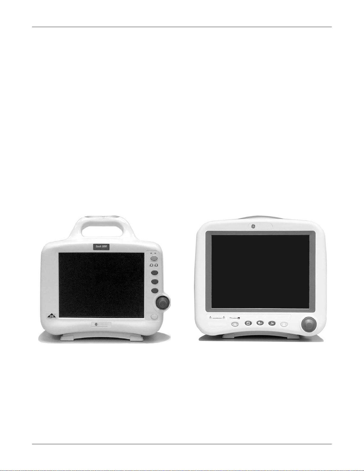
Components
The Monitoring System
The monitor can function by itself with a built-in writer, or it can be
cabled in with the optional Unity Network
components are, if using Wireless LAN or cabled to Ethernet, a
Centralscope™ central station and the Clinical Information Center
(CIC).
Dash 3000/4000 Monitor
This device is designed to monitor a fixed set of parameters including
ECG, noninvasive blood pressure, impedance respiration, SpO2, and
temperature. Invasive pressure and EtCO2 are optional features.
Additional specialized features include cardiac output, cardiac
calculations, pulmonary calculations, dose calculations, PA wedge (PA
wedge is only avai lable wi th the in vasive pr essure op tion), SA M
interface, and the ICG module interface.
The Basics: Components
®
via Ethernet. Optional
®
module
Dash 3000 Monitor, Front View
AC Battery
Power
Charging Status
A
Graph
NBP Go/Stop
Zero All
Trim Knob
Silence Alarm/
Admit
901A
B
Silence Alarm/
Zero AllNBP Go/StopGraph Go/StopPowerCharging Status
AB
Dash 4000
Admit
810B
Dash 4000 Monitor, Front View
Revision B Dash 3000/4000 Patient Monitor 1-3
2000966-171
Page 26
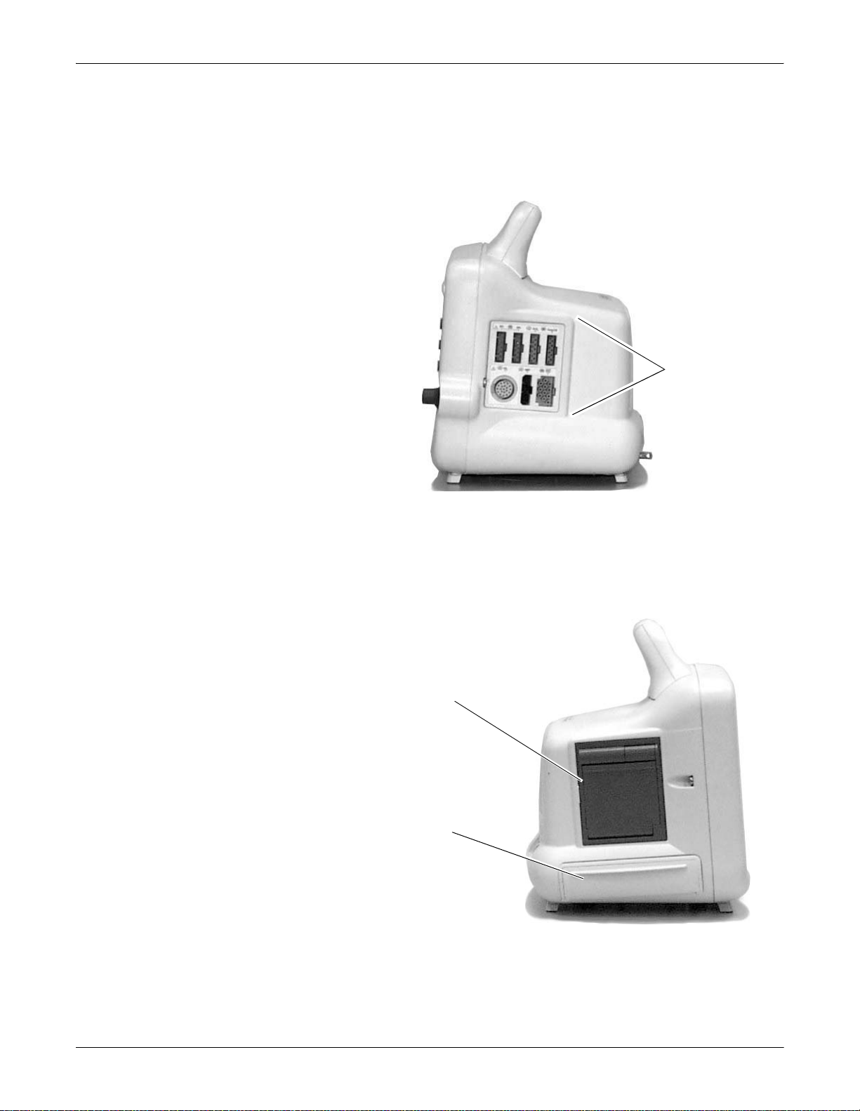
Right Side View
The Basics: Components
All of the patient cable connectors are located on the right side of the
monitor. The screen displays patient information in a logical, easily
understood format. A Trim Knob control provides single control
operation of virtually all monitor functions.
Patient Cable
Connectors
Left Side View
Monitor, Right Side View
On the left of the monitor, you can find the built-in writer and the
battery compartment.
Built-in Writer—The builtin, 4 channel writer is
located in the center of the
left side of the monitor.
Battery Compartment—
The battery packs are
located in this
compartment.
Monitor, Left Side View
1-4 Dash 3000/4000 Patient Monitor Revision B
2000966-171
Page 27
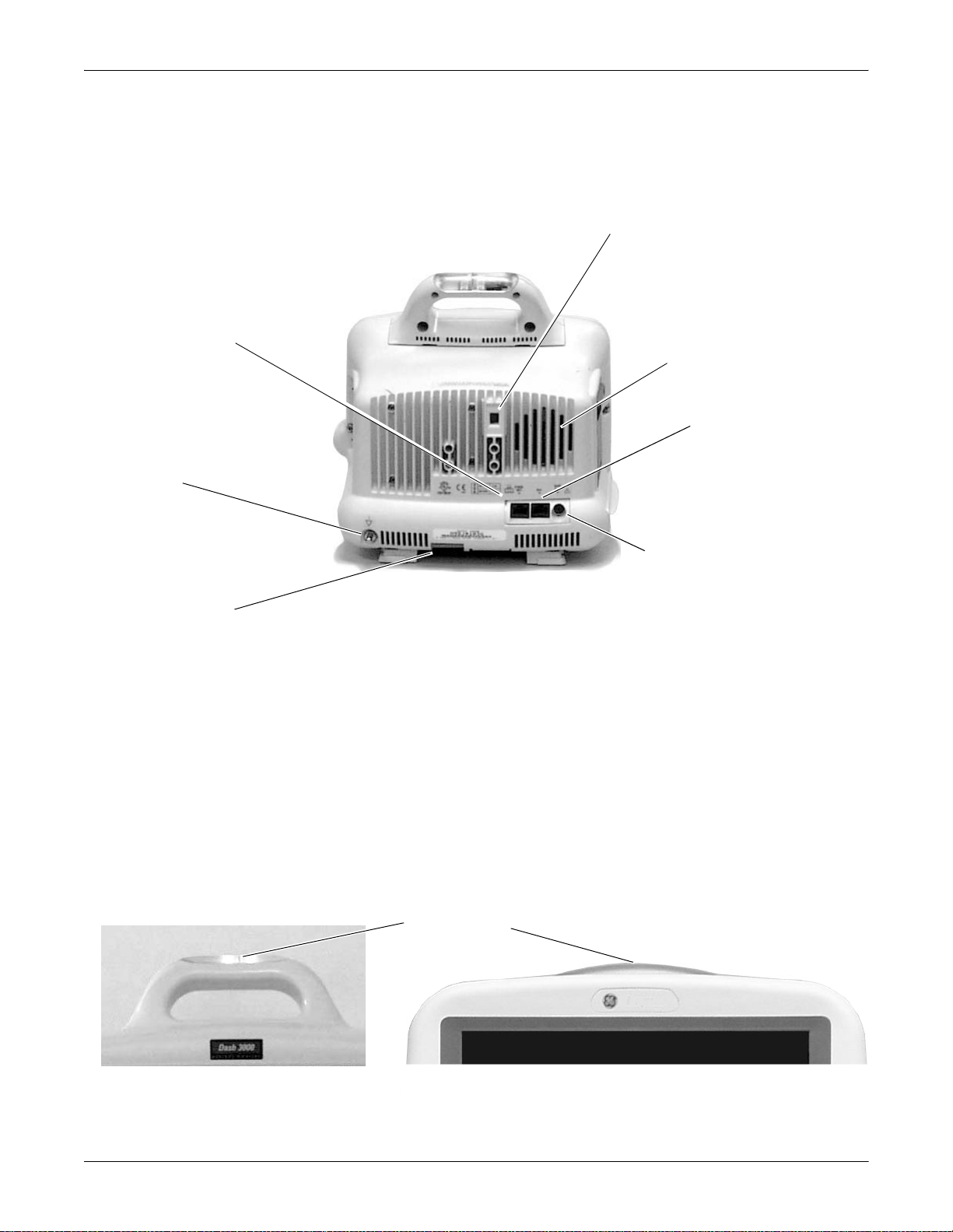
Back View
The Basics: Components
On the back of the monitor you will find all connectors for equipment and
network.
Line Voltage Selector—This selector is factory set to
match the line voltage and frequency rating for your
country.
Network Connector—A cable
can be connected to this port
for monitors used in patient
monitoring network
configurations.
Equipotential
Terminal
AC Power
Connector
Monitor, Back View
Audible Alarm Enunciator—The
internal speaker provides sound
for audible alarms. For better
sound quality do not block
speaker.
Aux Port—Used for:
RAC 2A module
housing and other
compatible auxiliary
devices.
Defib Sync Connector—Provides
ECG analog output signals to
user-supplied equipment. A 5volt, 2-millisecond artificial pacer
spike is added to the analog
output when PACE is on and
detection occurs. Refer to
Appendices, Analog Output, for
details on signal output.
Refer to the service manual for system safety requirements when
connecting the monitor to accessory equipment.
Optional Alarm Light Indicator
An optional alarm light indicator can be built into the handle of the Dash
3000 monitor or into the display bezel of the Dash 4000 monitor. When
activated, the LED indicator flashes red for CRISIS patient status
alarms and yellow for WARNING patient status and system status
alarms.
Dash 3000 Monitor, Alarm Light
Indicator
Alarm Light Indicator
Dash 4000 Monitor, Alarm Light Indicator
Revision B Dash 3000/4000 Patient Monitor 1-5
2000966-171
Page 28
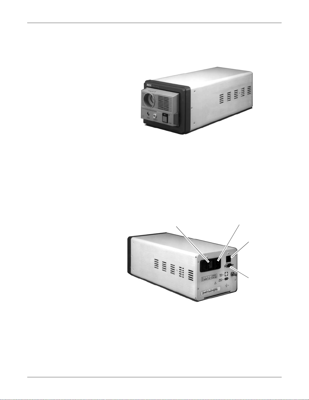
The Basics: Components
Optional RAC 2A Module Housing
The RAC 2A module housing currently supports the SAM or ICG module.
An integral power supply is used to run the module housin g and support
the needed voltages.
RAC 2A Module Housing
Housing Connectors
The module housing connects to the monitor via a communications cable
which plugs into the AUX port on the monitor and to the Auto Port on
the back of the module housing.
The module housing does not have an Analog Output connector.
Power Switch
Back View of RAC 2A Module Housing
AC Power
Auto Port
Async Comm
1-6 Dash 3000/4000 Patient Monitor Revision B
2000966-171
Page 29
The Basics: Components
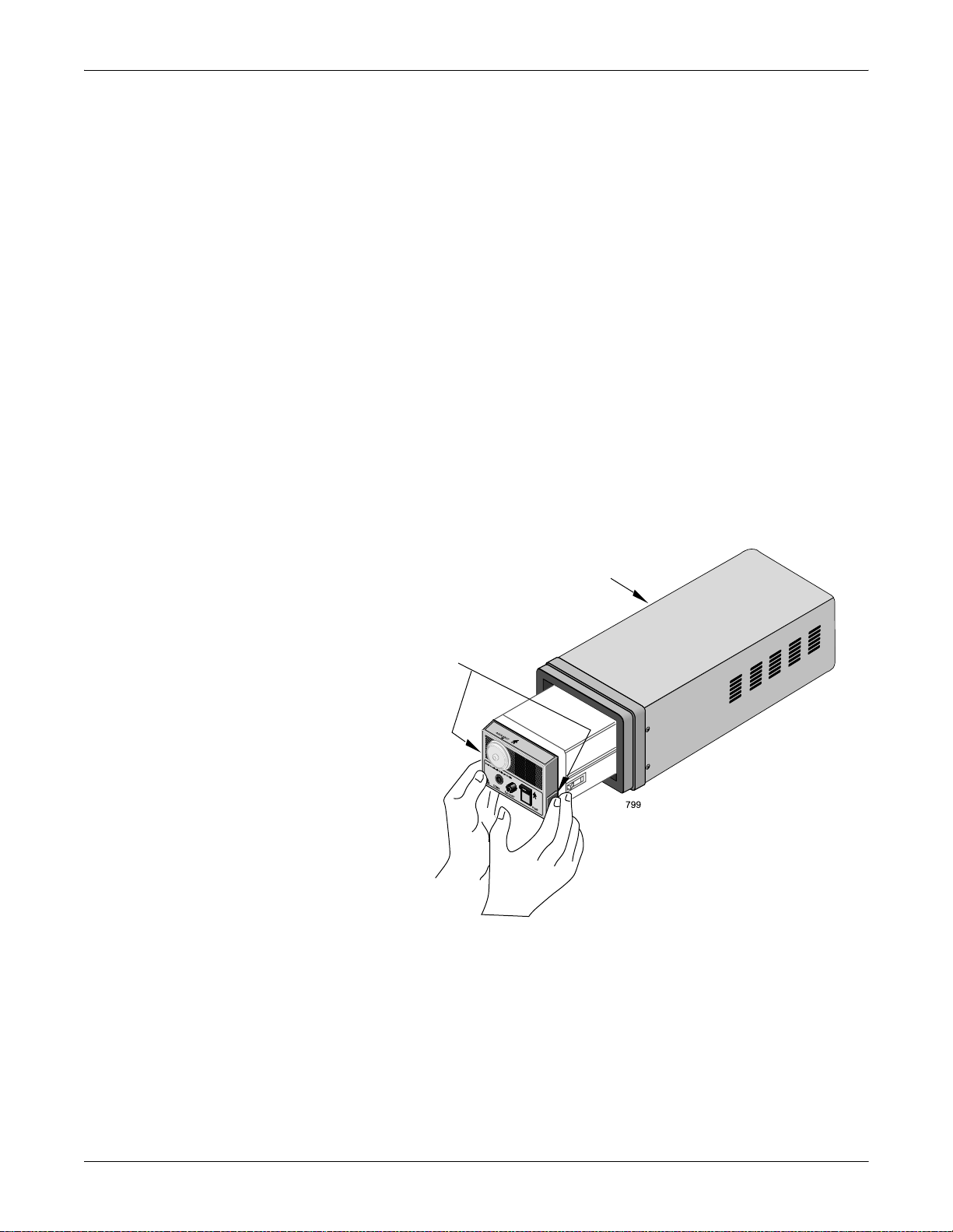
How to Install and Remove a Module
A module can be easily installed and removed.
To install a module follow this procedure:
1. Facing the module housing, guide the back end of the modul e into the
slot.
2. Gently push the module into the housing. You will hear a click when
the module is fully inserted.
To remove a module follow this procedure:
1. Release levers are found on each side on the front of the module*.
2. Press and hold the release l evers sim ultaneo usly and p ull the module
out about six inches.
3. Once released, grasp the module firmly with both hands and remove
the rest of the way. Do not try to hold the m o dule by the release
levers.
*The release levers for SAM modules are recessed in the side of the
protruding front of the module.
Release Levers
RAC 2A Module Housing
Removing a Sam Module
Revision B Dash 3000/4000 Patient Monitor 1-7
2000966-171
Page 30

The Basics: Components
Optional SAM Module Information
Disabling Halothane and Enflurane
When using the SAM module with the monitor, the detection of low
values of halothan e and enflurane, due to non-analyzed gases in the
circuit, can be disabled.
This option defaults off. If you do not want the system to detect and
display low values for halothane and enflurane, you must turn DISABLE
SAM HAL and DISABLE SAM ENF on. These options are found under
SETUP DEFAULT DISP LAY in the Monitor Defaults Menu.
127(Halothane and enflurane values greater than 1% are displayed
in the Gas parameter window even when this feature is on.
Values les s than 1% are not displayed.
Display MAC Value
When using the SAM module with the monitor, the current MAC value
can be displayed in the GAS parameter window. The MAC value is the
minimum alveolar concentration of an agent needed to produce an
anesthetizing effect in 50% of the population.
This option defaults off but can be turned on in Monitor Defaults under
SETUP DEFAULT DISP LAY. Thi s option can als o be turned on/off us ing
the DISPLAY MAC VALUE menu op tion from the Gas Menu.
When on, the MAC value is displayed in the third agent slot in the Gas
parameter window.
127(If N2O and two oth er agent s are bein g displayed , the MAC val ue
will not appear in the Gas parameter window.
GAS Parameter Window Displaying MAC Value
:$51,1*
These MAC values correspond to healthy adults. Other
factors such as age and physical condition need to be
accounted for.
1-8 Dash 3000/4000 Patient Monitor Revision B
2000966-171
Page 31

The Basics: Components
Optional ICG Module
The ICG module (impedance cardiography) measures and processes
patient hemodynamic data. For more information, see the “Patient
Monitoring System Operator’s Manual Supplement for the Solar ICG
Module.”
902A
Revision B Dash 3000/4000 Patient Monitor 1-9
2000966-171
Page 32

The Basics: Components
Optional Centralscope Cent ral Station
127(The Unity Network is a purchased software option which must
be enabled before using this component or feature.
The Unity Network (Ethernet) establishes bed-to-bed communication
and allows patient data to be sent to an optional Centralscope central
station and to other monitors on the network. All devices must be
connected to the network.
The central station may have a built-in, 2-inch writer or a laser printer
for graphing (printing).
Centralscope Central Station
The Centralscope central station is generically referred to as the central
station throughout this manual.
Refer to the Centralscope central station operator’s manual for
instructions on operation.
1-10 Dash 3000/4000 Patient Monitor Revision B
2000966-171
Page 33

The Basics: Components
Optional Clinical Information Center
127(The Unity Network is a purchased software option which must
be enabled before using this component or feature.
The Unity Network (Ethernet) establishes bed-to-bed communication
and allows patient data to be sent to an optional Clinical Information
Center and to other monitors on the network. All devices must be
connected to the network.
Clinical Information Center
The Clinical Information Center is generically referred to as the central
station throughout this manual.
Refer to the Clinical Information Center operator’s manual for
instructions on operation.
Revision B Dash 3000/4000 Patient Monitor 1-11
2000966-171
Page 34

The Basics: Components
Optional Wireless LAN System
127(The Unity Network is a purchased software option which must
be enabled before using this component or feature.
The flexibility of the GE Unity Network is increased by using the
Wireless LAN syste m. The W irele ss LA N system al lows the use r to roam
from one access point to another, maintaining a strong, seamless
connection to the Unity Network.
A monitor, with its optional built-in Wireless LAN, functionally performs
the same as a monitor connected directly to the Unity Network. It can be
viewed at the central station and by other GE monitors on the network
(i.e. Dash 3000/4000, Eagle
Monitors with Wireless LAN sends and receives patient data via the
access points of the Unity Network.
127(Wireless patient monito rs that are moved from room to room
must have the monitor type configured as Rover or Rover/Combo
monitoring.
®
4000, and Solar® patient monitor s ).
Access Points
To integrate the wireless network with the wired network, one or more
access points are necessary. An access point connects the wireless
monitor to the wired network infrastructure within the building, and
acts as a bridge between the wired and wireless networks. The areas
covered by each access point overlap to insure continuous coverage.
1-12 Dash 3000/4000 Patient Monitor Revision B
2000966-171
Page 35

The Basics: Components
Establish Communication
Approximately one minut e after power-up of the w ireless moni tor (or any
other time during normal operation) , perform one or more of the
following steps to verify network communication. If any one of these
steps is successful , the wire less monitor has acc ess to the Unity Net wor k.
n
Select VIEW OTHER PATIENTS at the wireless monitor and
attempt to view a known bed on the network. Refer to the
appropriate monitor’s operator’s manual.
n
View the wireless monitor from a central station on the ne twork.
Refer to the appropriate central station’s operator’s manual .
n
Perform a LIST NETWORK from the central station on the network
and verify that the wireless monitor appears in the list. Refer to the
appropriate central station service manual.
n
Ensure that the defaults and graph locations are set at the patient
monitor according to the appropriate operator’s manual.
Unity Network Switching and Priority
Hardwired or wireless network communica tion is transparent to th e user
and is not indicated on the display.
The transition between hardwired and wireless network communication
occurs automatically when a Category 5 unshielded twisted pair cable is
disconnected from the Ethernet port of an RF LAN enabled monitor.
Hardwired communication is established when the cable is connected.
Each transition occurs within 3 seconds of connecting or disconnecting
an Ethernet cable. The hardwired Ethernet connection has priorit y when
an RF LAN card is installed.
Revision B Dash 3000/4000 Patient Monitor 1-13
2000966-171
Page 36

Troubleshooting
The Basics: Components
Loss of Waveform
Due to the nature of the Wireless LAN system, loss of waveform data
may occasionally occur. Intermittent small gaps in the display waveform
may be caused by radio-frequency interference.
Problem Solution
Loss of waveform occurs in a
specific location.
An intermittent radio-frequency
interference at 2.4 GHz is in
close proximity to the wireless
monitor.
Call service personnel to determine if more access
points are required for better coverage or if there are
any compatibility issues between the Wireless LAN
and access points.
Try to isolate the source and move the wireless
monitor away from the interfering device.
Microwave ovens can be strong sources of 2.4 GHz
radio-frequency interference.
Remove the source of interference, if possible.
Communication Problems
Extended loss of communication will cause the NO COMM message to
appear at the central statio n. This fault may be due to one of th e network
communication problems described in the table below.
Problem Solution
The monitor, with built-in
Wireless LAN adapter, was
moved outside the Wireless
LAN coverage area.
Move the patient into the coverage area.
One of the access points in the
system may have failed.
A strong radio-frequency
interference at 2.4 GHz is in
close proximity to the Wireless
LAN adapter.
1-14 Dash 3000/4000 Patient Monitor Revision B
2000966-171
Try moving the patient to another portion of the
Wireless LAN coverage area.
Replace a failed access point with one known to work
properly.
Try to isolate the source and move the wireless
monitor away from the interfering device.
Remove the source of interference, if possible.
Page 37

Optional Laser Printer
The Basics: Components
An optional laser printer (not shown) connects to the central station. It is
identified on the monitor as L ASER when choosing a graph location.
(Refer to the Monitor Setup chapter for more details.)
When you choose the laser printer as the print window location, it can
print any printable infor mation window when it is display ed and the
GRAPH GO/STOP key is pressed.
127(The GRAPH GO/STOP key is located on the monitor and on the
optional remote control.
When you choose the laser printer as the manual graph location, it will
print the waveforms as selected in Graph Setup when the GRAPH GO/
STOP key is pressed. It prints 20 seconds of waveforms per page in a
cascade format when the graph speed is set for 25 millimeters per
second. There will be a delay of approximately one minute until the first
page is printed, then it will run until all patient data is printed.
127(The one-minute delay do es not mean the data printed i s dela yed.
It just takes that long for the information to be processed by the
laser printer. The amount of data printed will increase and the
delay will be longer if a speed slower than 25 mm/s is chosen.
When you choose the laser printer as the alarm graph location, it will
provide 20 seconds of waveforms per page in a cascade format, but again,
there will be a delay of one minute until the first page is printed.
Revision B Dash 3000/4000 Patient Monitor 1-15
2000966-171
Page 38

Controls and Indicators
Trim Knob
NBP Go/Stop
Zero All
Silence Alarm/
Admit
Graph
Power
Charging Status
A
B
AC Battery
Dash 3000 Control Panel
814A
815A
Control Panel
On the control panel there are five control keys. Their functions are
described below. Press the control key to activate the function. The Trim
Knob
A
B
C
The Basics: Components
®
control is also found on the control panel.
901A
Item Dash 4000 Icon Description
A
Power
B
Graph Go/Stop
D
F
AB
Dash 4000
Dash 4000 Control Panel
Silence Alarm/
Zero AllNBP Go/StopGraph Go/StopPowerCharging Status
Admit
E
810B
ABCDE F
The monitor will be powered at all times when plugged into AC power. This key turns
the monitoring function ON and OFF. When the monitoring function is turned off,
patient monitoring is discontinued; however, patient data already accumulated is
retained and the battery charging function continues.
127(To prevent inadvertently turning the monitoring function
ON or OFF, this key must be depressed for 0.25 seconds
before the function is activated.
Press this key once to start a graph run of the patient’s data. Press a second time to
stop. If pressed during an alarm graph run, the graph will run continuously until Graph
Go/Stop is pressed again. Note that an alarm graph run is usually an automatic 20second timed graph.
This key is also used to print a copy of non-real time screens. We refer to these as
information windows. Not all information windows can be printed. If a printable
information window is displayed, press Graph Go/Stop to print a copy. If a
nonprintable information window is displayed, pressing the Graph Go/Stop key prints
patient data as if the information window was not displayed.
1-16 Dash 3000/4000 Patient Monitor Revision B
2000966-171
Page 39

The Basics: Components
816A
817A
818A
Item Dash 4000 Icon Description
C
NBP Go/Stop
D
Zero All
E
Silence Alarm/
Admit
This key starts one noninvasive blood pressure measurement. It can also be used at
any time to stop a measurement in process.
In Operating Room Mode, if an auto mode time is set in monitor defaults, pressing the
NBP Go/Stop key starts the auto mode feature.
This key zeros all invasive pressure lines which are open to atmosphere. Each
pressure can also be zeroed, if desired, with a menu option in the pressure menu.
The function of this key can be set to NORMAL or SILENCE ONLY (refer to the Monitor
Setup chapter, Setup Default Display). When set to NORMAL, this key silences a
current, audible alarm for 60 seconds. Only new alarms of equal or higher level
interrupt the silence command.
:$51,1*
Alarms do not sound, alarm histories are not stored,
alarm graphs do not print, and alarms are not sent
to the central stations during an “Alarm Pause”
condition.
Press the key twice during an alarm to start an alarm pause (five minutes for AdultICU, 3 minutes for Neonatal-ICU). Press the key again during the alarm pause to
reactivate alarms.
If no alarm is sounding, press this key to start an alarm pause.
If your monitor is set up for Operating Room mode, you have three levels of alarm
pause:
n
Press once (if an alarm is sounding you must press twice) to start a 5-minute alarm
pause;
n
Press again to start a 15-minute alarm pause;
n
Press again to start a permanent alarm pause;
n
Press again to reactivate alarms.
When set to SILENCE ONLY, this key works as a silence key. Press once to silence
alarms; press again to reactivate alarms. Pressing this key when no alarms are
occurring does not affect the monitor.
This key also allows you to quickly admit a patient by simply pressing this key when the
monitor is in a discharged state.
F
Trim Knob control
The main operator control is the Trim Knob control. The Trim Knob control rotates in
either direction to highlight parameter labels and menu options. After highlighting the
desired selection, press the Trim Knob control to view a new menu or a small popup
menu. This procedure is referred to as “select” throughout the manual.
Remember, when using the Trim Knob control, rotate to highlight, then press to select.
Revision B Dash 3000/4000 Patient Monitor 1-17
2000966-171
Page 40

Optional Remote Control
The Basics: Components
An optional hand-held remote control is also available. This can be used
in addition to, or instead of the monitor control keys, allowing the
clinician a greater range of movement while operating the monitor. The
remote control contains a Trim Knob control and 18 function buttons. It
is also available in three versions, Adult, Neonatal, and Operating Room.
An optional holster is also available to hold the remote control.
remote control
Aux port
DIDCA connector
Remote Control Connection
The remote control connects to the monitor via a communications cable
which plugs into a DIDCA connector before it is inserted into the Aux
port on the monit or or th e Da sh
®
Port docking station.
The table below shows the keys that appear on the remote control. It also
indicates which type(s) of remote control the key appears on, and gives a
brief description of its functi on.
Keys
Keypad Type(s) Function
12-Lead Adult Opens the 12 Lead ECG Analysis menu.
Admit/Discharge Adult, Neonatal Opens a menu to admit or discharge a patient.
Airway Gases: CO2 Operating Room Opens the CO2 menu.
Airway Gases: Gas Operating Room Opens the Gas menu.
Alarm Volume Neonatal Opens a menu to adjust the audio alarm volume.
900A
All Limits Adult, Neonatal Opens the All Limits menu to adjust the limits of currently monitored
parameters.
Cardiac Calcs Adult, Operating Room Opens the Cardiac Calcs menu.
1-18 Dash 3000/4000 Patient Monitor Revision B
2000966-171
Page 41

The Basics: Components
Keys
Keypad Type(s) Function
Cardiac Output Adult, Operating Room Opens the Cardiac Output menu.
CRG Events Neonatal Opens the Document CRG Events window.
CRG Print Neonatal Prints the CRG waveforms.
CRG Recall Neonatal Opens the CRG Trends menu at the most recent CRG event.
Defaults Adult, Neonatal, Operating Room Opens the defaults menu.
Display On/Off Adult, Neonatal, Operating Room Turns the monitor display, audio alarms, and optional alarm light off and
on. Operating power (mains) is still on, and alarms remain active at the
central station. Also turns NBP off.
Dose Calcs Neonatal Enters the dose calculations program.
Graph Go/Stop Adult, Neonatal, Operating Room Initiates a graph run of patient data. Press the key again to stop.
Graphic Trends Adult, Operating Room Opens the Graphic Trends menu.
Main Menu Adult, Neonatal, Operating Room Returns to the main display.
NBP Auto Adult, Operating Room Opens the NBP Auto menu.
NBP Go/Stop Adult, Neonatal, Operating Room Initiates an NBP measurement. Pressing this key while a measurement is
in process stops that measurement.
NBP Stat Adult, Operating Room Starts five minutes of continuous, sequential NBP measurements.
New Case Operating Room Performs the direct action of discharging and then immediately admitting
a patient.
PA Wedge Adult, Operating Room Opens the PA Wedge menu.
QRS Volume Neonatal Opens a menu to adjust the volume of the QRS tone.
Resp Relearn Neonatal Starts a relearn of the patient’s respiration.
Silence Alarm Adult, Neonatal, Operating Room Refer to “Controlling Audio Alarms” on page4-6 for important information
on the function of this key.
SpO2 Operating Room Opens the SpO2 menu.
Tabular Trends Operating Room Opens the Tabular Trends menu.
View Other Adult, Neonatal Opens the View Other Patients menu.
Vital Signs Adult, Neonatal Opens the Vital Signs menu.
Zero All Adult, Neonatal, Operating Room Zeros all invasive pressure lines that are open to atmosphere.
Revision B Dash 3000/4000 Patient Monitor 1-19
2000966-171
Page 42

Indicators
The Basics: Components
Power and battery indicators are also located on the front panel of the
monitor.
Indicator Dash 3000 Monitor Label Dash 4000 Monitor Label
AC power AC
819A
Battery power Battery
820A
Battery charge
A
B
822A
A
B
821A
AC Power Indicator
The indicator illuminates green when AC power is applied to the
monitor. The indicator is not illuminated when the monitor is not
powered.
Battery Power Indicator
The indicator illuminates yellow when the monitor is battery powered.
The indicator is not illuminated when the monitor is not powered or
when AC power is applied.
Battery Charging/Ready Indicator
An icon for each battery pack indicates its charging status. The battery
icon illuminates yellow when the respective battery is being charged. If
both batteries are present and require charging, then both icons will
illuminate even though they will be charged sequentially. The battery
icon illuminates green when the respective battery is fully charged.
When the monitor is operating unde r battery power the batte ry icons will
not be illuminated. The icons are also not illuminated when the
respective battery is either not being charged, not installed, or has failed.
127(No specific information is given to distinguish a failed battery
pack condition from a condition where the battery is not installed
or is not being charged.
1-20 Dash 3000/4000 Patient Monitor Revision B
2000966-171
Page 43

Turning Power On
AC Power
Normal Mode
The Basics: Turning Power On
The monitor will be powered at all times when using AC power (there is
no AC power switch). The monitor is preset at the factory for a specific
AC voltage. Before applying power, be sure the power requirements
match your power supply. Refer to the label on the back of the unit for
the voltage and current requirements. Refer also to Power Requirements
in the Safety chapter of this manu al.
When all cables are properly connected, press the power button to turn
the monitor on. All of the front panel indicators will illuminate until the
power-up sequence is complete. After approximately 10 seconds you
should see a display on the screen.
Two modes of operation a re available when using AC power . The monitor
will enter “NORMAL” mode when plugged into AC power and the
monitoring function is turned ON. Normal mode operation provides all
functional capabilities of the monitor including vital signs monitorin g,
communications, and battery charging.
Standby Mode
Off
Battery Power
The monitor will enter “STANDBY ” mode when plugged into AC power
and the monitoring function is turned OFF. The battery charging
function is the only function provided when the monitor is Standby mode.
To turn the monitor completely off, you must turn the monitoring
function off by pressin g the POWER key on the front of the monitor, and
then disconnect AC power. Indicators are not illuminated when the
monitor is not powered.
127(When monitoring a patient from Combo or Rover Combo on
telemetry, you will not be able to turn off the power to the
monitor until you have discharged the patient. If you press the
Power key during telemetry monitoring, the Discharge menu
appears. See the “Combo and Rover Combo Popup Menu to
Discharge” on page 3-20 for detailed information about the popup
menu options.
Dual, exchangeable battery packs provide power to the monitor for
transport or whenever AC power is interrupted. (Refer to the Batteries
chapter for more detailed information.)
Revision B Dash 3000/4000 Patient Monitor 1-21
2000966-171
Page 44

The Basics: Software Overview
Software Overview
Software Packages and Software Options
See “Appendix C – Softwa re Packages” on page C-1 for a complete
breakdown of the Basic, Cardiac, and Cardiopulmonary software
packages and the High Resolution CRG Trends software option.
Software Packages
The monitor comes configured with the Basic software package. This
package consists of standard-of-care parameters, lethal arrhythmia
detection, dose calculations, and features required by clinicians caring
for acutely ill patients.
Two additional software packages can be purchased separately or in any
combination. These packa ges provide a variety of features which al low
the monitor to be configured to best meet the needs of its intended
environment.
Software Options
The Cardiac software package focuses on cardiac conductivity. Its
features include full arrhythmia analysis and storage, as well as ST
segment trending, storage, and templates. The ability to adjust the ST
measurement point is also included in this package.
The Cardiopulmonary software package centers upon cardiac and
pulmonary hemodynamics. Fe at ure s include th e PA inse rt and wed ge
algorithms, the intra-aortic balloon pump algorithm, and the
thermodilution cardiac output algorithm, including predefined
computation constants for the catheters of major manufacturers. Also
included are cardiac and pulmonary calculations.
Three software options can be purchased separately or in any
combination with the software packages and software options.
The High Resolution CRG Trends option provides storage of up to 100
CRG events, and up to 24 hours of CRG trend data, in addition to the
CRG feature set found in the Basic software package.
The 12SL™ ECG an alysis program wi th Gender Specific Criteri a and the
Acute Cardiac Ischemia–Time Insensitive Predictive Instrument (ACITIPI) analysis option uses recorded ECG data to produce a numerical
score which is the predicted probability of acute cardiac ischemia. In
addition, the gender specific criteria improves the detection of acute
myocardial infarctions (AMI) for adult women under the age of 60.
The Unity Network option enables you to view other patients on the
network, interface with a central station and other network devices, and
perform Combo or Rover Combo monitoring.
1-22 Dash 3000/4000 Patient Monitor Revision B
2000966-171
Page 45

The Basics: Software Overview
How can you tell what software you have?
1. Select MORE MENUS from the monitor’s main display.
2. Select MONITOR SETUP from the menu displayed.
3. Select SOFTWARE CONFIGURATION from the Monitor Setup
Menu. An information window displays the software features this
monitor has available.
Revision B Dash 3000/4000 Patient Monitor 1-23
2000966-171
Page 46

Monitor Display
Care Unit and Bed Number
The Basics: Software Overview
Menus
Monitor Default Name
Date and Time
Parameter Waveforms
More Menus
A menu, like the name implies, is a selection of available options. These
options are displayed at the bottom of the screen and are accessed with
the Trim Knob control. Some menus may have some empty spaces. These
spaces are available for future software enhancements.
Patient Name
809A
Battery Capacity Gauges
Monitor Display
Menu Timeout
There are two important me nu options to note. One or both of these
options is found in every menu with the exception of the Main Menu.
This option will always take you back to the Main
Menu. Use it when you are finished making
adjustments or accessing stored information.
This option allows you to back up to the previous
menu when a subordinate menu is displayed.
Think of these as escape or exit options.
The monitor automatically returns to the Main Menu (refer to the figure
below) when you have displayed another menu and have not used the
Trim Knob for 5 minutes (def ault time). This is a Monitor Defa ult display
setting which can be set for a longer period of time or no timeout at all.
Some menus, such as Vital Signs and trends, are not affected by the
timeout setting. You must exit them using one of the exit options
described above.
1-24 Dash 3000/4000 Patient Monitor Revision B
2000966-171
Page 47

Main Menu
The Basics: Software Overview
The Main Menu has one menu option, MORE MENUS, in the lower left
corner of the screen. With the Main Menu d isplayed, t he screen shows all
monitored parameters and waveforms.
The Main Menu
Parameter Menus
From the Main Menu, you access a parameter menu by selecting the
appropriate parameter label, or you can access other menus (not related
to a specific parameter) by selecting the MORE MENUS option.
Each parameter has its own menu from which to access features. Below
is an example of the ECG parameter menu.
ECG Parameter Menu
The Main Menu must be displayed to access a parameter menu.
To access a parameter menu, highlight a parameter label, for example,
ECG, and then press the Trim Knob control.
Each parameter menu is discussed in detail in the specific parameter
chapter.
Revision B Dash 3000/4000 Patient Monitor 1-25
2000966-171
Page 48

More Menus
The Basics: Software Overview
In the lower left corner of the Main Menu is the MORE MENUS option.
Select this option to display the following menu.
More Menus Menu
n
ALARM CONTROL—This option displays a menu which allows you
to view and modify all alarm limits, change alarm levels, and adjust
alarm volume.
n
VIEW OTHER PATIENTS—This option displays a menu which
allows you to select any bedside monitor on the network to view at
this monitor. This data can be displayed contin uously, or you can
program the monitor to alert you when a bed alarms, then you
request a view. This is part of the Unity Network software option.
n
PATIENT DATA—This option displays a menu which allows you to
view patient data—alarm history, vital sign history, and graphic
trends—and enter calculation programs.
n
MONITOR SETUP—This option displays a menu which allows you
to set up the monitor to suit your needs—waveforms displayed, color
scheme, parameters on/off, graph setup, monitor defaults, etc. The
service menu is accessed here also.
n
ADMIT MENU—This option displays a menu to enter necessary
patient information and admit and discharge the patient to/from the
monitor. (In Operating Room mode, this option reads NEW CASE
SETUP.)
n
BATTERY STATUS—This menu option opens a menu and
information window that provides current battery status
information.
Each of these options is covered in more detail in following chapters.
1-26 Dash 3000/4000 Patient Monitor Revision B
2000966-171
Page 49

Popup Menus
↑
Scrolling Popup
The Basics: Software Overview
When some menu options are selected, a small menu “pops up” around
the selected menu option. These are called popup menus. There are
different types of popup menus. Those most commonly us ed are described
below.
Note that with all popup menus, the original menu remains on the screen
but the options are dimmed. The popup menu must be closed before you
can select other options from the original menu.
↓ ↑
Scrolling Popup Menu
Pointer Popup
All available selections appear with the current se le ction highlig hte d.
The arrows are also highlighted indicating that the Trim Knob control
can be rotated (scrolled) to change the selection. When the Trim Knob
control is rotated, the new selection is highlight ed and t he change occurs
immediately on the screen so that the user can see if the selection is
appropriate before exiting the popup. Press the Trim Knob control to
close the popup menu.
↓↓
↑
Pointer Popup Menu
All available selections appear and a pointer (>) is displayed. The arrows
are highlighted indicating that the Trim Knob control can be rotated to
move the pointer to another selection. However, before the change is
actually implemented, the Trim Knob control must be pressed. The
popup menu closes and the change is in effect.
Revision B Dash 3000/4000 Patient Monitor 1-27
2000966-171
Page 50

Numeric Popup
The Basics: Software Overview
↓ ↑
Numeric Popup Menu
The available selections are many; therefore, only the current selection is
displayed. The arrows are highlighted indicating the Trim Knob control
can be rotated. Rotate the Trim Knob control to enter a new value. Using
the number keys on the optional remote control also changes the
displayed value in the popup menu. Like the Pointer Popup, the change
will not be in effect until the Trim Knob control is pressed.
127(When a numeric popup menu is open, the keys on the optional
remote control can only be used to enter numbers. Close the
numeric popup menu to access features using the optional
remote control keys.
Subordinate Menus
Whenever possible, short popup menus are displayed when selecting
menu options. In some cases, however, a whole new menu is displayed.
This is a menu within a menu, or a subordinate menu.
Many, but not all, subordinate menus have the PREVIOUS MENU
option to allow you to return to the previously displayed menu.
Following is an example of a subordinate menu:
Display the ECG Menu.
From the ECG Menu select ECG LIMITS—the entire ECG Menu is
replaced with the subordinate ECG Limits Menu.
Select PREVIOUS MENU to redisplay the ECG Menu.
1-28 Dash 3000/4000 Patient Monitor Revision B
2000966-171
Page 51

The Basics: Software Overview
Direct Action Menu Options
A direct action menu option, when selected, displays neither a popup
menu nor a subordinate menu. The option either turns a feature on or
off, or starts a processing function. For example, selecting the SMART
BP: ON option from the ART parameter menu turns the Smart BP
feature off. In ON/OFF cases, the menu option reflects the current state;
selecting it switches to the other state.
SMART BP: ON
SMART BP: OFF
Other direct action options start a process. For example, selecting the
RELEARN option from the ECG parameter menu tells the monitor to
immediately start to relearn the patient’s ECG rhythm. You can’t stop
these processes a s the y ar e sho rt te rm an d sto p a uto mat ica ll y; t he refo r e,
the words identifying the menu option do not change as in ON/OFF
actions.
Revision B Dash 3000/4000 Patient Monitor 1-29
2000966-171
Page 52

Parameter Windows
The Basics: Software Overview
Parameter windows are displayed on the far right side of the screen, and,
when necessary, across the bottom. Every monitored parameter has a
parameter window.
Each parameter window has two parts—a parameter label and digital
values. Depending on how you have set yo ur defaul ts, limit s and uni ts of
measure may be displayed under the parameter label.
Digital Values
Parameter
Label,
Limits, Units
of Measure
ART Parameter Window
Parameter windows are displayed in different sizes depending on the
display layout and the number of parameters you are monitoring. Below
is an example of parameter wi ndows at doubl e high size (twi ce the height
of a normal parameter block), normal size, and reduced size.
ART Parameter Window, Double High Size
The double high parameter window is displayed when monitoring in the
INDV 3 WFS (individual 3 waveforms) display mode.
CO Parameter Window, Normal Size
CO Parameter Window, Reduced Size
Parameters windows which may be displayed in reduced size when
positioned at the bottom of the screen are: CO, CVP, ICP, LA, RA, RR,
SP, SPO2, TP, and UVC.
1-30 Dash 3000/4000 Patient Monitor Revision B
2000966-171
Page 53

Information Windows
The Basics: Software Overview
Another window that is sometimes displayed on the screen is called an
information window. This large window is superimposed over the upper
left portion of the screen. Up to six parameter windows and 2 seconds of
all the real-time waveforms continue to be displayed.
Information windows are displayed when a HELP option is selected and
with certain menu options, such as LIMITS. The information window
contains instructions or other non-realtime information.
Below is an example of an information window:
Information Window
More
Information
Indicator
Real-Time
Waveforms
The Vital Signs Information Window
Sometimes an information window will contain a list, for example, vital
signs. The window is limited to the amount of information that can be
displayed at one time. There may be more information to view, but not
enough room to display it at one time. If this is the case, an arrow will be
displayed at the bottom of the information window (see the figure above).
If a popup menu is displayed with the window, you must turn the Trim
Knob control to scroll to more information. If a menu is displayed, as in
the example above, you must select the PAGE UP or PAGE DOWN
option to display more information.
↓There is more information. Scroll down or use PAGE DOWN to
display more information.
↑↓You are in the middle of the list. Scroll up or down, or use
PAGE UP or PAGE DOWN to display additio nal in format io n.
↑You are at the end of the list. Scroll up or use PAGE UP to
display additional information.
Revision B Dash 3000/4000 Patient Monitor 1-31
2000966-171
Page 54

The Basics: Software Overview
Trim Knob Control Operation When Setting Alarm Limits
127(The Trim Knob control is found on the monitor and on the
optional remote control. See “Controls and Indicators” on page 1-
16.
127(You can use the number keys on the optional remote control for
setting parameter limits.
Limits which trigger alarms for monitored parameters can be modified.
You should refer to the specific parameter chapter for details. When
setting alarm limits, the f ollowing information is help ful and applies to
most parameters:
The Trim Knob control will always increase (or decrease) the displayed
number in increments of one for the first five numbers. Thereafter, it
increases (or decreases) in increments of five. There may be situations
where the limit you wish to modify does not fall into this incremental
sequence. For example, the low heart rate limit default is 50. For your
patient, a limit of 44 is desired.
The fastest way to achieve this using the Trim Knob control is to use the
following procedure:
1. Open the HR LOW LIMIT popup menu. The number 50 is displayed.
↓ ↑
HR LOW LIMIT Popup Menu
2. Rotate the Trim Knob control until the number reads 45. It will
follow this sequence: 49, 48, 47, 46, 45.
127(The next rotation will take the number to 40 which, in this
instance, is too low.
3. Close the popup menu when the number is 45 and immediately open
it again.
4. Rotate the Trim Knob control to 44.
127(Closing the popup menu and then reopening it allows you to
reset again in increments of one.
The same principle applies when setting limits for other parameters.
1-32 Dash 3000/4000 Patient Monitor Revision B
2000966-171
Page 55

Graphing (Prin ting)
Devices
You can print displayed information using the monitor’s built-in writer
or, via the optional network, using an optional writer and/or an optional
laser printer. This manual refers to a PRN 50 and DDW (Direct Digital
Writer) as writers and a laser printer as a printer.
The writer may be the monitor’s built-in writer or a stand-alone writer
connected to another monitor. Your system may include one or more
central stations. Some central stations come equipped with a built-in
writer. A writer can also be connecte d to the central st ation. The opt ional
laser printer always connects to a central station.
Patient waveforms and most information windows can be printed. You
choose which waveforms you want to print , to which device you want to
print, a duration time, and the speed at which manual graphs are
printed. These menu options are all found in the Graph Setup menu.
Refer to the Monitor Setup chapter for details.
The Basics: Graphing (Printing)
Manual Graphs
Exclusive Graph Control
Waveforms and information w indows are pri nt ed when t he GRAPH GO/
STOP key on the monitor or remote control is pressed. The message
“GRAPHING MANUAL” or “PRINTING WINDOW” is displayed when a
manual graph is requested. There is a setting in the Graph Setup Menu
which allows you to set a time for how long a manual graph runs (e.g.,
continuous, 20-seconds, etc.).
127(A one millivolt ECG signal at normal (1X) size equals 10
millimeters on the graph paper.
All waveforms on a graph strip begin with 10 seconds of delayed
data. The header information pri nted wi th t he wa veforms is rea ltime data.
Once a manual graph is started, it can only be stopped from the same
source from which it was started or from the Graph Stop key on the
writer. This is to pre vent two pe ople at different sources starting a graph
at the same time, which results in one turning the graph on and the
other turning the graph off.
Revision B Dash 3000/4000 Patient Monitor 1-33
2000966-171
Page 56

Alarm Graphs
Pressure Scales
The Basics: Graphing (Printing)
A graph strip is automatically printed when a Crisis or Warning alarm
occurs. An arrhythmia alarm graph will run until a normal s inus rhythm
is again detected or you manuall y stop the graph. Any ot her alarm gra ph
runs for 20 seconds or until you manually stop it.
127(To convert an arrhythmia alarm graph to a manual graph, you
must stop the graph using the Graph Stop key on the writer and
immediately restart the graph.
In Operating Room mode and Neonatal-ICU mode, the alarm graphing
default is off. There is a menu option in the Graph Setup menu (ALARM
GRAPH) to turn this feature on and off. This can be saved as a Monitor
Default. This option is not available in the Adult-ICU mode.
Invasive pressures will always graph on individual and full scales as
follows:
Displayed Scale Graph Scale
30 0-30 (PA, CVP, LA, RA, ICP)
40 0-45
60 0-60
100 0-90
160 0-150
200, 300 0-300
Auto 0-150 (ART, FEM, UAC, SP)
0-45 (PA, CVP, UVC, RA, LA, ICP)
1-34 Dash 3000/4000 Patient Monitor Revision B
2000966-171
Page 57

Graphing Messages
The Basics: Graphing (Printing)
Following is a list of all graphing messages and what they indicate:
SAVING—the device to which you want to print is busy or for some
reason inoperable. If it is an alarm graph, 20 seconds of data is saved
until it can print or another alarm graph occurs. The moni tor only saves
for print the most recent alarm data. A manual graph is saved until you
press the GRAPH GO / STOP key or an alarm graph occurs.
GRAPHING MANUAL—a manual graph is in progress.
GRAPHING ALARM —a crisis or warning alarm has occurred. An
automatic graph is run.
PRINTING WINDOW—a manual graph of a printable information
window is in progress.
PAPER OUT—the writer/printer needs paper or a writer door is open.
127(If saved graph never prints or graph does not print at your
central station, check all graph locations then verify the graph
location setting. (Re f er to GRAPH LOCATION in the Monitor
Setup chapter.)
Graph Header
The graph header which is printed with all patient waveforms, includes:
n
type of graph (alarm, manual, or saved)
n
*alarm violation* (if any)
n
unit name, bed number, and patient name
n
date and time
n
patient-monitor type label (ICU has no label)
n
alarm volume level (%)
n
graph speed
n
lead failed (if any)
n
heart rate
n
arrhythmia call (if any and arrhythmia is on)
n
pace mode (if on)
n
arrhythmia mode (off, lethal, or full)
n
PVC count (if full arrhythmia is on)
n
ST value (if on) for top displayed lead
n
ECG filter (Hz range)
n
values for all other monitored parameters
Revision B Dash 3000/4000 Patient Monitor 1-35
2000966-171
Page 58

The Basics: Putting the Monitor Into Operation
Putting the Moni to r Into Operation
Monitor Installation and Connection
:$51,1*
Before using the monitor for the first time, please read
the information given in chapter 2 “Safety”.
The operating position d oes not i nfluen ce the p erformance of the monit or
in any way.
n
Choose a location which affords an unobstructed view of the monitor
screen and easy access to the operating controls.
n
Set up the device in a location which affords sufficient ventilation.
The ventilation openings of the device must not be obstructed (by
external equipment, walls or blankets, for instance). The ambient
conditions specified in the Technical Specifications section of the
Dash 3000/4000 Patient Monitor Service Manual must be ensured at
all times.
n
The monitor is designed to comply with the requirements of IEC
60601/EN 60601.
n
Using the power cord supplied with the monitor, connect it to the
power line. Use only the original cord or an equivalent one.
:$51,1*
The monitor must be connected to a properly installed
power outlet with protective earth contacts only. If the
installation doe s not provide for a protective earth
conductor, disconnect the monitor from the power line
and operate it on battery power.
n
For measurements in or near the heart we recommend connecting
the monitor to the potential equalization system. Use the green and
yellow potential equalization cable and connect it to the pin labeled
with the symbol.
n
Our customer service engineers can be called in to connect the
monitor to a central station.
:$51,1*
For safety reasons, all connectors for patient cables and
sensor leads are designed to prevent inadvertent
disconnection, should someone pull on the leads. Do not
route cables in a way that they may present a stumbling
hazard. Do not install the monitor in a location where it
may drop on the patient. All consoles and brackets used
must have a raised edge at the front.
1-36 Dash 3000/4000 Patient Monitor Revision B
2000966-171
Page 59

Performance Check
The Basics: Putting the Monitor Into Operation
n
Monitors may be shipped with protective covers to protect unused
parameter connector inputs from dust an d liquids.
127(Do not remove these cove rs, the parameter connect ors do not
function.
:$51,1*
After connecting the monitor to the central station, verify
the function of the alarm system. This can be done, for
instance, by temporarily changing one of the alarm limits
to initiate an alarm.
n
Turn on the device with the power switch on the front of the monitor.
All of the front panel indicators will illuminate until the power-up
sequence is complete.
n
The monitor display appears after approximately 10 seconds.
After power up and during operation the monitor runs automatic selftests. When a malfunction is detected, the monitor displays a message
and a prompt, asking whether the user wishes to continue operation.
:$51,1*
If this message appears during operation, it is the
physician’s responsibility to decide whether the unit is
still suitable for patient monitoring. As a general rule,
monitoring with this unit should continue only in
extremely urgent cases and under the supervision of a
physician. The unit must be repaired before being used
again on a patient. If this message appears after power
up, the unit must be repaired before being used on a
patient.
:$51,1*
After connecting the monitor to a central station, verify
the function of the alarm system. This can be done, for
instance, by temporarily changing one of the alarm limits
to initiate an alarm.
Revision B Dash 3000/4000 Patient Monitor 1-37
2000966-171
Page 60

The Basics: Language-Specific Information
Language-Specific Infor m ation
The following information describes differences in the monitor
functionality when the monitor is se t to certain languages (Locale).
French Language Information
When the monitor Locale (language) is set to French_France, alarm
pause duration is three minutes. Refer to “Pausing Alarms” on page 4-6.
Hungarian, Polish, and Russian, Language Information
Special ch aracter s with in alarm broad casts, m essage s, pati ent name , site
name, or location fields that are sent over the Unity Network cannot be
displayed by equipment that does not support these langua ges. Special
characters may appear as either blanks, asterisks, a series of square
boxes, or no character is displayed at all because the ability to display
Cyrillic (Russian alphabet) and special Hungarian or Polish characters
does not exist on this equipment.
Chinese and Japanese Language Information
When the monitor Locale (language) is set to Japanese, the following
conditions apply:
n
Text for alarm broadcast over the network is in English.
n
All text input is in English only (i.e., text for unit name, bed name,
patient information, and custom default name).
1-38 Dash 3000/4000 Patient Monitor Revision B
2000966-171
Page 61

2 Safety
Revision B Dash 3000/4000 Patient Monitor 2-1
2000966-171
Page 62

For your notes
2-2 Dash 3000/4000 Patient Monitor Revision B
2000966-171
Page 63

For Your Safety
Intended Use
Terminology
Safety: For Your Safety
The intended use of the monitoring system is to monitor physiologic
parameter data on adult, pediatric, and neonatal patients within a
hospital or facility providing patient care.
Physiologic data includes the parameters covered in this manual. The
monitoring system is also intended to provide physiologic data over the
optional Unity Network to clinical information systems. This information
can be displayed, trended, stored, and printed.
The terms danger, warning, and caution are used throughout this
manual to point out hazards and to designate a degree or level or
seriousness. Familiarize yourself with their definitions and significance.
Monitor Safety
Hazard is defined as a source of potential injury to a person.
DANGER indicates an imminent hazard which, if not avoided, will
result in death or serious injury.
WARNING indicates a potential hazard or unsafe practice which, if not
avoided, could result in death or serious injury.
CAUTION indicates a potential hazard or unsafe practice which, if not
avoided, could result in minor personal injury or product/property
damage.
NOTE provides application tips or other useful information to assure
that you get the most from your equipment.
The safety statements presented in this chapter refer to the equipment
in general and, in most cases, apply to all aspects of the monitor. There
are additional safety statements in the paramet er chapters which are
specific to that monitored parameter.
The order in which safety statements are presented in no way implies
order of importance.
Dangers
There are no dangers that refer to the equipment in general. Specific
"Danger" statements may be given in the respective sections of this
manual.
Revision B Dash 3000/4000 Patient Monitor 2-3
2000966-171
Page 64

Warnings
Safety: For Your Safety
:$51,1*6
ACCIDENTAL SPILLS — To avoid electric shock or
device malfunction, liquids must not be allowed to enter
the device. If liquids have entered a device, take it out of
service and have it checked by a service technician before
it is used again.
ACCURACY — If the accuracy of any value displayed on
the monitor, central station, or printed on a graph strip is
questionable, determine the patient's vital signs by
alternative means. Verify that all equipment is working
correctly.
ALARMS — Do not rely exclus iv el y o n th e a udib le al a rm
system for patient monitoring. Adjustment of ala rm
volume to a low level or off during patient monitoring
may result in a hazard to the patient. Remember that the
most reliable method of patient monitoring combines
close personal surveillance with correct operation of
monitoring equipment.
After connecting the monitor to the central station and/or
nurse-call system, verify the function of the alarm
system.
The functions of the alarm sy stem for monitoring of the
patient must be verified at regular intervals.
BEFORE USE — Before putting the system into
operation visually inspect all connecting cables for signs
of damage. Damaged cables and connectors must be
replaced immediately.
Before using the system, the operator must verify that it
is in correct working order and operating condition.
Periodically, and whenever t he integri ty of the product is
in doubt, test all functions.
CABLES — Route all cables away from patient's throat
to avoid possible strangulation.
CONDUCTIVE CONNECTIONS — Extreme care must
be exercised when applying medical electrical equi pment.
Many parts of the human/machine circuit are conduct ive,
such as the patient, connectors, electrodes, transducers.
It is very important that these conductive parts do not
come into contact with other grounded, conductive parts
when connected to the isolated patient input of the
device. Such contact would bridge the patient's isolation
and cancel the protection provided by the isolated input.
In particular, there must be no contact of the neutral
electrode and ground.
2-4 Dash 3000/4000 Patient Monitor Revision B
2000966-171
Page 65

Safety: For Your Safety
:$51,1*6
DEFIBRILLATION — Do not come into contact with
patients during defibrillation. Otherwise serious injury
or death could result.
DISCHARGE TO CLEAR PATIENT DATA — When
admitting a new patient, you must clear all previous
patient data from the system. To accomplish this,
disconnect patient cables then do a discharge.
DISCONNECTION FROM MAINS — When
disconnecting the syst em from the power line, remo ve the
plug from the wall outlet first. Then you may disconnect
the power cord from the device. If you do n ot observe t his
sequence, there is a risk of coming into contact with line
voltage by inserting metal objects, such as the pins of
leadwires, into the sockets of the power cord by mistake.
DISPOSAL — Dispose of the packaging material,
observing the applicable waste control regulations and
keeping it out of children's reach.
EXPLOSION HAZARD — Do not use this equipment in
the presence of flammable anesthetics, vapors or liquids.
INCOMPATIBILITY — Wireless LAN equipment
contains an intentional RF radiator that has the
potential of interfering with other medical equipment,
including patient implanted devices. Be sure to perform
the electromagnetic compatibility test, as described in
the Wireless LAN System Installation and Service
Manual, before installation and any time new medical
equipment is added to the Wireless LAN coverage area.
INTERFACING OTHER EQUIPMENT — Devices may
only be interconnected with each other or to parts of the
system when it has been determined by qualified
biomedical engineering pe rsonnel that t here is no danger
to the patient, the operator, or the environment as a
result. In those instances where there is any element of
doubt concerning the safety o f connected devices, t he user
must contact the manufacturers concerned (or other
informed experts) for proper use. In all cases, safe and
proper operation should be verified with the applicable
manufacturer's instructions for use, and system
standards IEC 60601-1-1/EN 60601-1-1 must be complied
with.
Revision B Dash 3000/4000 Patient Monitor 2-5
2000966-171
Page 66

Safety: For Your Safety
:$51,1*6
INTRACARDIAC APPLICATION — When applying
devices intracardiall y, ele ctr i cally cond uc tiv e cont act
with parts connected to the heart (pressure transducers,
metal tube connections and stopcocks, guide wires, etc.)
must be avoided in all cases.
To prevent electrical contact, we recommend the
following:
n
always wear isolating rubber gloves,
n
keep parts that are conductively connected to the
heart isolated from ground,
n
if possible, do not use tube fittings or stopcocks made
of metal.
During intracardiac ap plication of a device, a
defibrillator and pacemaker whose proper functioning
has been verified must be kept at hand.
LEAKAGE CURRENT TEST — When interfacing with
other equipment, a test for leakage current must be
performed by qualified b iome dical eng in eering p erso nnel
before using with patients.
PATIENT AMBULA TION — A patient must be assisted
if ambulating with a roll-stand mounted monitor.
POWER SUPPLY — The device must be connected to a
properly installed power outlet with protective earth
contacts only. If the installation does not provide for a
protective earth conductor, disconnect the monitor from
the power line and operate it on battery power, if
possible.
All devices of a system must be connected to the same
power supply circuit. Devices which are not connected to
the same circuit must be electrically isolated when
operated
PROTECTED LEADWIRES — Only use protected
leadwires and patient cables with this monitor. The use
of unprotected leadwires and patient cables creates the
potential for making an electrical connection to ground or
to a high voltage power source which can cause serious
injury or death to the patient.
Unprotected Leadwire
2-6 Dash 3000/4000 Patient Monitor Revision B
2000966-171
Protected Leadwire
Page 67

Safety: For Your Safety
:$51,1*6
RATE METERS — Keep pacemaker patients under close
observation. Rate meters may continue to count the
pacemaker rate during cardiac arrest and some
arrhythmias. Therefore, do not rely entirely on rate
meter alarms.
SITE REQUIREMENTS — For safety reasons, all
connectors for patient cables and sensor leads are
designed to prevent inadvertent disconnection, should
someone pull on them. Do not route cables in a way that
they may present a stumbling hazard. For devices
installed above the patient, adequate precautions must
be taken to prevent them from dropping on the patient.
Revision B Dash 3000/4000 Patient Monitor 2-7
2000966-171
Page 68

Cautions
Safety: For Your Safety
&$87,216
ACCESSORIES (SUPPLIES) — To ensure patient safety,
use only parts and accessories manufactured or
recommended by GE Medical Systems Information
Technologies.
Parts and accessories used must meet the requirements
of the applicable IEC 60601 series safety standards and
essential performance standards, and/or the system
configuration must meet the requirements of the IEC
60601-1-1 medical electrical systems standard.
ACCESSORIES (EQUIPMENT) — The use of
ACCESSORY equipment not complying with the
equivalent safety requirements of this equipment may
lead to a reduced level of safety of the resulting system.
Consideration relating to the choice shall include:
n
use of the accessory in the PATIENT VICINITY; and
n
evidence that the safety certification of the
ACCESSORY has been performed in accordance to
the appropriate IEC 60601-1 and/or IEC 60601-1-1
harmonized national standard.
BATTERY POWER — If a device equipped with an
optional battery pack will not be used or not be connected
to the power line for a period of over six months, remove
the battery.
BEFORE INSTALLATION — Compatibility is critical to
safe and effective use of this device. Please contact your
local sales or service representative prior to installation
to verify equipment compatibility.
CO2 PARAMETER INTERFERENCE — Capnostat CO2
sensors with a serial number 26104 or greater require a
separation distance of 10 inches (0.25 meters) from the
Wireless LAN device to minimize potential interference.
CO2 sensors with a serial number less than 26104
require a separation distance of 8.2 feet (2.5 meters) and
are not recommended for use on monitoring equipment
equipped with the Wireless LAN option.
DEFIBRILLATOR PRECAUTIONS — Patient signal
inputs labeled with the CF and BF symbols with paddl es
are protected against da mage resulting from
defibrillation voltages. To ensure proper defibrillator
protection, use only the recommended cables and
leadwires.
Proper placement of defibrillator paddles in relation to
the electrodes is required to ensure successful
defibrillation.
2-8 Dash 3000/4000 Patient Monitor Revision B
2000966-171
Page 69

Safety: For Your Safety
&$87,216
DISPOSABLES — Disposable devices are intended for
single use only. They should not be reused as
performance could degrade or contamination could occur.
DISPOSAL — At the end of its service life, the product
described in this manual, as well as its accessories, must
be disposed of in compliance with the guidelines
regulating the disposal of such products. If you have
questions concerning disposal of the product, please
contact GE Medical Systems Information Technologies or
its representatives.
ELECTROCAUTERY PRECAUTIONS — To prevent
unwanted skin burns, apply electrocautery electrodes as
far as possible from all other electrodes, a distance of at
least 15 cm/6 in. is recommended.
EMC — Magnetic and electrical fields are capable of
interfering with the prop er performance of the device.
For this reason make sure that all external devices
operated in the vicinity of the monitor comply with the
relevant EMC requirements. X-ray equipment or MRI
devices are a possible source of interference as they may
emit higher levels of electromagnetic radiation.
INSTRUCTIONS FOR USE — For continued safe use of
this equipment, it is necessary that the listed
instructions are followed. However, instructions listed in
this manual in no way supersede established medical
practices concerning patient care.
LOSS OF DATA — Should the monitor at any time
temporarily lose patient data, the potential exists that
active monitoring is not being done. Close patient
observation or alternate monitoring devices should be
used until monitor function is restored.
If the monitor does not automa t icall y re s um e ope ratio n
within 60 seconds, power cycle the monitor using the
power on/off switch. Once monitoring is restored, you
should verify correct monitoring state and alarm
function.
Operation of an access point or Wireless LAN device in
close proximity to a microwave oven may cause loss of
patient data.
MAINTENANCE — Regular preventive maintenance
should be carried out annually. You are responsible for
any requirements specific to your country.
Revision B Dash 3000/4000 Patient Monitor 2-9
2000966-171
Page 70

Safety: For Your Safety
&$87,216
MPSO — The use of a multiple portable socket outlet
(MPSO) for a system will result in an enclosure leakage
current equal to the sum of all individual earth leakage
currents of the system if there is an interruption of the
MPSO protective earth conductor. Do not use an
additional extension cable with the MPSO as it will
increase the chance of the s ingle protective earth
conductor interruption.
NEGLIGENCE — GE Medical Systems Information
Technologies does not assume responsibility for damage
to the equipment caused by improperly vented cabinets,
improper or faulty power, or insufficient wall strength to
support equipment mounted on such walls.
OPERATOR — M edi cal tec hnic al e quip men t suc h as th is
monitor/monitoring system must only be used by persons
who have received adequate training in the use of such
equipment and who are capable of applying it properly.
POWER REQUIREMENTS — Before connecting the
device to the power line, check that the voltage and
frequency ratings of th e po wer line a re t he same a s those
indicated on the unit's label. If this is not the case, do not
connect the system to the power line until you adjust the
unit to match the power source.
In U.S.A., if the installation of this equipment will use
240V rather than 120V, the source must be a centertapped, 240V, single-phase circuit.
RESTRICTED SALE — U.S. federal law restricts this
device to sale by or on the order of a physician.
SUPERVISED USE — This equipment is intended for
use under the direct supervision o f a l icense d healt h care
practitioner.
VENTILATION REQUIREMENTS — Set up the device
in a location which affords sufficient ventilation. The
ventilation opening s of the device must no t be obstructed.
The ambient conditions specified in the technical
specifications must be ensured at all times.
ELECTRODES — Whenever patient defibrillation is a
possibility, use non-polarizing (silver/silver chloride
construction) electrodes for ECG monitoring. Polarizing
electrodes (stainless steel or silver constructed) may
cause the electrodes to retain a residual charge after
defibrillation. A residual charge will block acquisition of
the ECG signal.
2-10 Dash 3000/4000 Patient Monitor Revision B
2000966-171
Page 71

Notes
Reference Literature
Safety: For Your Safety
n
Put the monitor in a l ocation where you can ea sily se e the scree n and
access the operating controls.
n
This product is not likely to cause abnormal operation of other
patient-connected equipment such as cardiac pacemaker or other
electrical stimulators. Exceptions are noted in the pacemaker
monitoring section, if applicable.
n
This product is protected against the effects of cardiac defibril la tor
discharges to ensure proper recovery, as required by test standards.
(The screen may blank during a defibrillator discharge but recovers
within seconds as required by test standards.)
Medical Device Directive 93/42/EEC
EN 60601-1/1990 + A1: 1993 + A2: 1995: Medical electrical equipment.
General requirements for safety
EN 60601-1-1/9.1994 + A1 12.95: General requirements for safety.
Requirements for the safety of medical electrical systems.
IEC Publication 513/1994: Fundamental aspects of safety standards for
medical equipment.
ROY, O.Z.: Summary of cardiac fibrillation thresholds for 60-Hz currents
and voltages applied directly to the heart. Med. & Biol. Engn. &
Computing 18: 657...659 (1980).
Revision B Dash 3000/4000 Patient Monitor 2-11
2000966-171
Page 72

Classifications
4P41
Safety: Classifications
The equipment components are classified, according to IEC-60601-1, as:
electrical shock
Type of protection against
Dash 3000/4000 monitor I BF—NBP
ICG module NA BF Ordinary Not Suitable NA Continuous
Remote control NA Not Marked Ordinary Not Suitable NA Continuous
electrical shock
Degree of protection against
BF—SPO2
BF—CO2
CF—ECG
CF—Temp/
CO
CF—Resp
CF—BP
the manufacturer
harmful ingress of water
Degree of protection against
Ordinary Not Suitable NA Continuous
anesthetic mixture with air or
Degree of safety of application
in the presence of a flammable
with oxygen or nitrous oxide
Method(s) of sterilization or
disinfection recommended by
Underwriters Laboratories, Inc.
Medical Equipment
With respect to electric shock, fire and mechanical hazards only in
accordance with UL 2601-1, and CAN/CSA C22.2 NO. 601.1.
Mode of operation
I: Class I equipment
B: Type B applied part
BF: Type BF applied part
CF: Type CF applied part
NA: Not applicable
Ordinary: Ordinary
equipment (enclosed
equipment without protection
against ingress of water)
Not Suitable: Equipment not
suitable for use in the
presence of a flammable
anesthetic mixture with air or
with oxygen or nitrous oxide
2-12 Dash 3000/4000 Patient Monitor Revision B
2000966-171
Page 73

Equipment Symbols
127(The rating
of protection
against electric
shock (indicated by
symbol for CF or
BF) is achieved only
when used with
patient applied
parts recommended
by GE Medical
Systems
Information
Technologies.
Safety: Classifications
127(Some symbols may not appear on all equipment.
ATTENTION: Consult accompanying documents
CAUTION: To reduce the risk of electric shock, do NOT remove cover. Refer servicing to
qualified service personnel.
TYPE CF APPLIED PART: Isolated (floating) applied part suitable for intentional external and
internal application to the patient including direct cardiac application. "Paddles" outside the
box indicate the applied part is defibrillator proof.
[Medical Standard Definition:] F-type applied part (floating/isolated) complying with the
specified requirements of IEC 60601-1/UL 2601-1/CSA 601.1 Medical Standards to provide a
higher degree of protection against electric shock than that provided by type BF applied parts.
TYPE BF APPLIED PART: Isolated (floating) applied part suitable for intentional external and
internal application to the patient excluding direct cardiac application. "Paddles" outside the
box indicate the applied part is defibrillator proof.
[Medical Standard Definition:] F-type applied part (floating/isolated) complying with the
specified requirements of IEC 60601-1/UL 2601-1/CSA 601.1 Medical Standards to provide a
higher degree of protection against electric shock than that provided by type B applied parts.
TYPE B APPLIED PART: Non-isolated applied part suitable for intentional external and
internal application to the patient excluding direct cardiac application.
[Medical Standard Definition:] Applied part complying with the specified requirements of IEC
60601-1/UL 2601-1/CSA 601.1 Medical Standards to provide protection against electric
shock, particularly regarding allowable leakage current.
Fuse
Equipotentiality
Alternating current (AC)
Power; I = ON; O = OFF
PRESS Indicates where to press to open the door on the DDW.
Revision B Dash 3000/4000 Patient Monitor 2-13
2000966-171
Page 74

For your notes
Safety: Classifications
2-14 Dash 3000/4000 Patient Monitor Revision B
2000966-171
Page 75

3 Admit Discharge
Revision B Dash 3000/4000 Patient Monitor 3-1
2000966-171
Page 76

For your notes
3-2 Dash 3000/4000 Patient Monitor Revision B
2000966-171
Page 77

Admit Discharge: About Admitting
About Admitting
You Must Admit to Activate Alarms
Admitting a patient to the monitor is important. Audible alarms are OFF
and there will be no alarm graphs and alarm history until the monitor is
in the admit mode. The following message is displayed near the middle of
the screen to alert you to admit your patient:
ADMIT PATIENT TO ACTIVATE ALARMS
Monitors are Used in Different Ways
What you do to admit a patient to the monitor depends on how the
monitor is used. There are fo ur ways in which the monitor is used.
The Unity Network is a purchased software option which must be
enabled before using the Combo or Rover Combo monitoring application.
ALL ALARMS OFF
STANDARD—This application uses a monitor mounted in t he room.
It does not accommodate telemetry. A network connection is not
required unless you have a central station.
ROVER—With this application you can move, or “rove,” the monitor
to the patient, rather than moving the patient to a monitored room.
It does not accommodate telemetry. A network connection is not
required unless you have a central station.
COMBO—This application provides the option to acquire ECG data
from either the monitor or from a telemetry receiver cabinet. This
ECG data acquisition capability enhances basic telemetry
monitoring by providing additional access to all of the available
parameters from the monitor. A network connection is required.
ROVER COMBO—This application combines the mobility feature
of Rover monitoring with the telemetry compatibility of Combo
monitoring. A network connection is required.
It is determined at the time of installation which application applies. At
that time a menu option in the service mode is used to set your monitor
for one of the above applications. The information that is necessary for
successful admission to the monitor and the network is then provided in
the Admit Menu.
Revision B Dash 3000/4000 Patient Monitor 3-3
2000966-171
Page 78

Admit Discharge: About Admitting
Guidelines When Doing Combination Monitoring
127(The Unity Network is a purchased software option which must
be enabled before usin g th e Com b o or Ro v er Com b o m onitoring
application.
Here are some guidelines to remember when doing combination (Combo
and Rover Combo) monitoring:
n
When monitoring ECG from telemetry, ECG limits and arrhythmia
alarm levels are not your monitor defaults but are the telemetry
defaults or as modified at the central station. You can, however,
adjust these settings at the monitor.
n
Alarm histories (arrhythmia only) from the monitor are merged in
the telemetry system when switching ECG monitoring from monitor
to telemetry (CD Telemetry-LAN software version 5 or later is
required).
n
When ECG monitoring is switched from telemetry to the monitor,
telemetry is automatically discharged and the most recent 36 alarm
histories are transferred to the monitor.
n
When monitoring ECG from telemetry, the alarm pause feature (if
available on your transmitter) is honored at the monitor.
n
If you switch ECG monitoring from telemetry to monitor, the ECG
limits, arrhythmia alarm levels, and display formats will be recalled
from Monitor Defaults.
n
If you discharge the monitor and switch ECG monitoring from the
monitor to telemetry, the telemetry arrhythmia alarm levels will be
the same as the arrhythmia alarm levels supported by the monitor.
Therefore, when the monitor uses the Basic software package, only
lethal arrhythmia alarm levels will be detected from telemetry. If the
monitor has the Cardiac software package enabled, full arrhythmia
alarm levels will be detected from telemetry.
127(The Basic software package detects lethal arrhythmias and
the Cardiac software package detects full arrhythmias.
127(When monitoring a patient from Combo or Rover Combo on
telemetry, you will not be able to turn off the power to the
monitor until you have discharged the patient. If you press the
Power key during telemetry monitoring, the Discharge menu
appears. See the “Combo and Rover Combo Popup Menu to
Discharge” on page 3-20 for detailed information about the popup
menu options.
For Which Application is the Monitor Set?
The ADMIT HELP menu option opens an information window that tells
you the application for which the monitor is set along with admit
instructions for that application. Refer to this chapter, Admit Help, for
more detailed information.
3-4 Dash 3000/4000 Patient Monitor Revision B
2000966-171
Page 79

Admit Discharge: Getting to the Admit Menu
Getting to the Admit Menu
1. Select MORE MENUS from the Main Menu to display the following
menu.
2. Select ADMIT ME NU. The admit menu and the Admit Information
window are displayed.
127(When monitoring ECG, entering the sex and age of the patient
will provide information needed for using the 12SL Algorithm
with Gender-Specific Analysis or t h e ACI-TIPI algorithm. The
12SL Algorithm wit h Ge nd er Spec i fi c Analy s is imp rov e s th e
detection of acute myocardial infarctions (AMI) for adult women
under the age of 60.
More Menu Selections
542B
Admit Menu and Information Window
The admit menu displayed depends on how your monitor has been set up.
The following pages describe the various admit menus.
Revision B Dash 3000/4000 Patient Monitor 3-5
2000966-171
Page 80

Admit Discharge: Standard Admit Menu
Standard Admit Menu
With the Standard application, the monitor is permanently assigned to a
room. The unit name and bed number are assigned during installation.
The options you may need to adjust/enter are shown in the admit menu
below.
ADMIT MENU (Adult/Neonatal)—Standard Application
NEW CASE SETUP (OR)—Standard Application
CHANGE ADMIT INFO—open an information window with menu
options to enter/cha nge patient information such as name, ID, etc.
REQUEST ADMIT INFO—use to request patient information from a
server with an interface to hospital information.
RECALL DEFAULT—open a popup menu that allow you to recall one of
the Multiple Monitor Defaults
ADMIT HELP—opens an information window with admit help
information for the monitor application you are using.
127(This option is not found in OR mode.
ADMIT PATIENT—a direct action menu option which admits the
patient to the monitor.
NEW CASE—a direct action menu option which discha rges the pa tient ’s
data and, with no additional steps, readies the monitor for the next
patient (new admission).
127(This option is found in OR mode only.
UNITS OF MEASURE—opens a popup menu that allow you to change
the units of measure for height and weight .
Refer to this chapter, Admit Menu Options, if you need more details on
these menu options.
3-6 Dash 3000/4000 Patient Monitor Revision B
2000966-171
Page 81

Rover Admit Menu
With the Rover application, the monitor may be on a cart which allows
you to move it from one room to another. T he unit name and bed number,
in some cases, may need to be changed so they are included as options in
the admit menu.
Admit Discharge: Rover Admit Menu
ADMIT MENU (Adult/Neonatal)—Rover Application
NEW CASE SETUP (OR)—Rover Application
CHANGE ADMIT INFO—open an information window with menu
options to enter/cha nge patient information such as name, ID, etc.
REQUEST ADMIT INFO—use to request patient information from a
server with an interface to hospital information.
RECALL DEFAULT—open a popup menu that allow you to recall one of
the Multiple Monitor Defaults.
ADMIT HELP—opens an information window with admit help
information for the monitor application you are using.
127(This option is not found in OR mode.
ADMIT PATIENT—a direct action menu option which admits the
patient to the monitor.
NEW CASE—a direct action menu option which discha rges the pa tient ’s
data and, with no additional steps, readies the monitor for the next
patient (new admission).
127(This option is found in OR mode only.
UNITS OF MEASURE—opens a popup menu that allow you to change
the units of measure for height and weight .
SET UNIT NAME—verify or change the unit name. The correct unit
name is essential for recognition at a central station and other network
devices.
SET BED NUMBER—verify or change the assigned bed number. The
correct bed number is essential for recognition at a central station and
other network devices.
GRAPH LOCATION—display a new menu to select writers for manual
and alarm graphs.
Revision B Dash 3000/4000 Patient Monitor 3-7
2000966-171
Page 82

Combo Admit Menu
127(The Unity Network is a purchased software option which must
With the Combo application, the monitor is permanently assigned to a
room, and you have the ability to obtain patient ECG data from a module
or from a telemetry tran s mitt er .
The unit name and bed number are assigned during installation. The
options you may need to ad just/enter are shown in the admit menu
below.
Admit Discharge: Combo Admit Menu
be enabled before using the Combo monitoring application.
ADMIT MENU (Adult/Neonatal)—Combo Application
NEW CASE SETUP (OR)—Combo Application
127(It is not likely that the Combo a pplication is used when the
monitor is set for Operating Room mode.
CHANGE ADMIT INFO—open an information window with menu
options to enter/cha nge patient information such as name, ID, etc.
REQUEST ADMIT INFO—use to request patient information from a
server with an interface to hospital information.
RECALL DEFAULT—open a popup menu that allow you to recall one of
the Multiple Monitor Defaults.
ADMIT HELP—opens an information window with admit help
information for the monitor application you are using.
127(This option is not found in OR mode.
ADMIT PATIENT—a direct action menu option which admits the
patient to the monitor.
UNITS OF MEASURE—opens a popup menu that allow you to change
the units of measure for height and weight .
ECG SOURCE—choose either the monit or or a telemetry transmitter
from which to receive the patient’s ECG data.
Refer to this chapter, Admit Menu Options, if you need more details on
these menu options.
3-8 Dash 3000/4000 Patient Monitor Revision B
2000966-171
Page 83

Admit Discharge: Rover Combo Admit Menu
Rover Combo Admit Menu
127(The Unity Network is a purchased software option which must
be enabled before using the Rov er Combo moni tori ng appl icat ion.
With this application you are combining the Rover and the Combo
applications into one. The monitor may be on a cart w hich allows you to
move it from one room to another and ECG data can be obtained from a
module or from a telemetry transmitter.
ADMIT MENU (Adult/Neonatal)—Rover Combo Application
NEW CASE SETUP (OR)—Rover Combo Application
127(It is not likely that the Rover Combo application is used when
the monitor is set for Operating Room mode.
CHANGE ADMIT INFO—open an information window with menu
options to enter/cha nge patient information such as name, ID, etc.
REQUEST ADMIT INFO—use to request patient information from a
server with an interface to hospital information.
RECALL DEFAULT—open a popup menu that allow you to recall one of
the Multiple Monitor Defaults.
ADMIT HELP—opens an information window with admit help
information for the monitor application you are using.
127(This option is not found in OR mode.
ADMIT PATIENT—a direct action menu option which admits the
patient to the monitor.
UNITS OF MEASURE—opens a popup menu that allow you to change
the units of measure for height and weight .
SET UNIT NAME—verify or change the unit name. The correct unit
name is essential for recognition at a central station and other network
devices.
Revision B Dash 3000/4000 Patient Monitor 3-9
2000966-171
Page 84

Admit Discharge: Rover Combo Admit Menu
SET BED NUMBER—verify or change the assigned bed number. The
correct bed number is essential for recognition at a central station and
other network devices.
ECG SOURCE—choose either the monit or or a telemetry transmitter
from which to receive the patient’s ECG data.
Refer to this chapter, Admit Menu Options, if you need more details on
these menu options.
3-10 Dash 3000/4000 Patient Monitor Revision B
2000966-171
Page 85

Admit Discharge: Admit Menu Options
Admit Menu Options
Change Admit Info
The CHANGE ADMIT INFO option allows you to change or enter
information pertinent to the monitored patient.
1. Select CHANGE ADMIT INFO option from the Admit Menu. An
information window with menu options are displayed.
↓ ↑
532B
CHANGE ADMIT INFO Popup Menu and Information Window
2. Rotate the Trim Knob control to move the pointer (>); press, turn,
press to enter characters or make selections.
Revision B Dash 3000/4000 Patient Monitor 3-11
2000966-171
Page 86

Admit Discharge: Admit Menu Options
3. When all information is entered select RETURN. A prompt appears
giving you the option to SAVE or DO NOT SAVE CHANGES.
Selecting an option will close the popup and return you to the
Change Admit Info menu.
Name: enter up to 10 characters for the first name and 16 characters
for the last name. The name (at least part if not all) is displayed on
the monitor and central station, and printed on all graph headers.
(Refer to the figure on page 3-16 for location of the patient name on
the monitor.)
Patient ID: enter up to 13 characters. This is important information
to enter if you have a MUSE
®
Cardiology Information System or a
Lab Access Server. If not entered the monitor uses a default of all 9’s
for MUSE system storage.
Sex: select male or female.
Birth Date: enter the patient’s birth date. AGE is automatically
calculated.
Age: automatically calculated when the birth date is entered. Age is
calculated in years for adults and weeks, days, or years for neonates
(weeks if age is greater than 14 days but less than 2 years, days if
age is less than 14 days, and years if age is greater than 2 years). If
you enter an age, the birth date is calculated with current day and
month and appropriate year.
Height, Weight: enter the patient’ s height and weight.
Race: scroll through the selections in the popup menu to select the
patient’s race.
Secondary ID: if you need to enter a secondary ID, use this popup
menu to enter up to 13 characters.
Ref Physician: enter up to 16 characters for the referring
physician’s name and/or number.
3-12 Dash 3000/4000 Patient Monitor Revision B
2000966-171
Page 87

Request Admit Info
Admit Discharge: Admit Menu Options
127(The Unity Network is a purchased software option which must
be enabled before using this component or feature.
If your monitoring system includes a Lab Access Server with an interface
to hospital information, selecting this option will display patient
information that was entered. (See the figure below. ) If your system does
not have this equipment, a message i s displayed below the menu when
you attempt to select this option.
Name, ID, Sex, and Birth Date
come from hospital information.
Age is calculated i f a birth date has
been entered.
The remaining information will be
displayed if previously entered. If
necessary you can add to or
change the information displayed.
View Manual Admit Info
Recall Default
533B
REQUEST ADMIT INFO Information Window and Menu
Verify the accuracy of any displayed information. Use the CHANGE
ADMIT INFO option if any information needs to be corrected or
additional information entered.
127(If you change any information which was supplied
automatically, you may have to notify the appropriate hospital
personnel.
This option allows you to view admit information that has been entered
manually. This key is only displayed when patient data is retrieved from
a server with an interface to hospital information.
This menu option allows you to recal l previousl y named monito r defaults
while monitoring an admitted patient. (Refer to the Monitor Setup
chapter, Monitor Defaults for more details.)
Revision B Dash 3000/4000 Patient Monitor 3-13
2000966-171
Page 88

Admit Help
Admit Discharge: Admit Menu Options
This option opens an information window that tells you the application
for which the monitor is set along with admit instructions for that
application.
1. Select MORE MENUS from the Main Menu.
2. Select ADMIT ME NU.
3. Select ADMIT HELP to display the following popup menu and
information window.
Admit Patient
Admit Patient
New Case
↓ ↑
ADMIT HELP Information Window
Depending on how your monitor is set up, you wi ll see either ADMIT
PATIENT or NEW CASE.
This menu option is a direct action menu option which admits the patient
to the monitor. Simply select the key to admit the patient.
This menu option is found only when the monitor is set for Operating
Room mode and Standard or Rover admit menu.
It is a direct actio n menu option which, when selected, does both a
discharge and immediate admit.
All patient data fr om the pr evious patient is era sed, th e scree n blank s for
a few seconds, and then the monitor is ready for the next patient.
3-14 Dash 3000/4000 Patient Monitor Revision B
2000966-171
Page 89

Quick Admit
Units of Measure
Admit Discharge: Admit Menu Options
The Quick Admit feature allows you to admit a patient by simply
pressing the Silence Alarm/Admit key on the monitor or the Admit/
Discharge key on the optional remote control.
127(The Admit/Discharge key is only available in the Adult-ICU
and Neonatal-ICU remote controls.
This menu option opens a popup menu tha t allow you to chan ge the units
of measure for the weight displayed between LBS and KG and the units
of measure for the height displayed be tween CM and INCHES.
In neonatal mode, this option also allows you to change the units of
measure for the patient’ s age displayed between days, weeks, and years.
Revision B Dash 3000/4000 Patient Monitor 3-15
2000966-171
Page 90

Set Unit Name
Admit Discharge: Admit Menu Options
This menu option is found in the Rover and Rover Combo admit menus.
The unit name is very important for sending information to central
stations and writers.
Find the unit name at the top right of the display (CCU, ICU, etc.). Is
this the name which identifies your unit?
Unit name /bed number
Location of Unit, Bed Number and Name on the Monitor
If it is not the correct unit name follow this procedure to change it:
1. Select SET UNIT NAME option from the Admit Menu. An
information window is displayed with the available unit names.
Patient Name
↓ ↑
SET UNIT NAME Popup Menu
2. Rotate the Trim Knob control to move the pointer (>) in front of the
correct unit name.
3. Press the Trim Knob co ntro l. The informa tio n wi ndo w clos es and the
new unit name appears at the top of the monitor.
127(If the monitor is not on the network, a text entry popup menu
will open.
3-16 Dash 3000/4000 Patient Monitor Revision B
2000966-171
Page 91

Set Bed Number
Admit Discharge: Admit Menu Options
This menu option is found in Rover and Rover Combo admit menus.
Another essential elem ent to reco gnize t he monitor on the ne twork is the
bed number. Look to the r ight of the unit name on the display. The bed
number assigned to this monitor is displayed. (See the figure on the
previous page.)
Follow this procedure to confirm that the bed number is correct:
1. Select SET BED NUMBER from the Admit Menu. A popup menu
and information window are displayed.
Graph Location
↓ ↑
SET BED NUMBER Popup Menu
2. Use the Trim Knob control to move the pointer in front of the correct
bed number.
3. If the bed number you need is not listed, select CREATE NEW BED.
A text entry popup menu opens.
127(If the monitor is not on the network, a text entry popup menu
will open.
The GRAPH LOCATION option displays a menu which allows you to
choose writers for alarm and manual graphs. This option is used mostly
if the monitor does not have the optional built-in writer. The graph
location should be changed whenever the monitor is moved from one unit
to another. Refer to GRAPH LOCATION in the Monitor Setup chapter
for more detailed information.
Revision B Dash 3000/4000 Patient Monitor 3-17
2000966-171
Page 92

ECG Source
Admit Discharge: Admit Menu Options
This menu option is found in Combo and Rover Combo admit menus.
This menu option, which is unique to thos e monitors which can obtain
ECG data from telemetry is used to tell the monitor where to get the
ECG information.
Follow this procedure:
1. Select ECG SOURCE: option from the Admit Menu. A popup menu
and an information window are displayed.
↓ ↑
ECG SOURCE Popup Menu and Information Window
The information window li sts the possible sources from which the
ECG data can be obtained. The transmitter numbers listed are those
transmitters assigned to the unit.
2. Rotate the Trim Knob control to move the pointer (>) in front of the
source of choice. Select MONITOR if your patient’s ECG cable is
connected to the monitor. If your patient is wearing a telemetry
transmitter, select the transmitter number that matches the one on
the back of the transmitter.
3. Press the Trim Knob control to close the popup menu and
information window. If you chose a transmitter numb er, that number
(TTX) needs to be admitted before it will appear in the ECG
parameter window.
4. Select ADMIT PATIENT to admit the transmitter. The TTX number
now appears in the bottom of the ECG parameter window.
3-18 Dash 3000/4000 Patient Monitor Revision B
2000966-171
Page 93

About Discharging
When it is no longer necessary to monitor a patient, a discharge
procedure must be done to clear the system of all patient data collected.
Monitor defaults are always recalled when a discharge is done. The last
unit name and bed number used are retained. Patient name is cleared.
To discharge a patient, select ADMIT MENU from the More Menus
selections. Depending on how your monitor is set up, you will see either
DISCHARGE PATIENT or NEW CASE.
Discharge Patient
Admit Discharge: About Discharging
:$51,1*
DISCHARGE TO CLEAR PATIENT DATA—When
admitting a new patient, you must clear all previous
patient data from the system. To accomplish this,
disconnect patient cables then do a discharge.
This menu option indicates that t he patient is admitted. You select it to
discharge the patient.
Standard and Rover Admit Menu
To discharge a patient from the Standard and Rover admit menu follow
this procedure:
1. Select MORE MENUS.
2. Select ADMIT ME NU.
3. Select DISCHARGE PATIENT from the Admit Menu. A popup menu
opens.
4. Disconnect all patient cables.
5. Rotate the Trim Knob contro l to mov e the point er to DISCHARGE.
↓ ↑
Standard and Rover Popup Menu to Discharge
6. Press the Tri m Kno b cont rol . T he mess ag e “ DISCHARGED” appears
at the top of the display and all data is cleared from the system.
Revision B Dash 3000/4000 Patient Monitor 3-19
2000966-171
Page 94

Combo and Rover Combo
Admit Discharge: About Discharging
To discharge a patient from the Combo and Rover Combo admit menu
follow this procedure:
1. Select MORE MENUS.
2. Select ADMIT ME NU.
3. Select DISCHARGE PATIENT to display the following popup menu.
↓ ↑
Combo and Rover Combo Popup Menu to Discharge
4. Rotate the Trim Knob control to move the pointer (>) in front of:
a. RETURN if you do not want to discharge.
b. MONITOR to discharge patient from the monitor only. If ECG
was from telemetry, telemetry will remain admitted, but will not
be monitored by this monitor. The central st ation will continue t o
monitor the telemetry.
New Case
c. TELEMETRY to discharge patient from telemetry only. ECG will
automatically switch to monitor.
d. BOTH to discharge patient from telemetry and monitor.
5. Press the Trim Knob control to complete the discharge.
This menu option is displayed only when the monitor is set for Operating
Room mode and is found in Standard and Rover admit menus.
This menu option clears patient information from the monitor. With no
additional steps, the monitor is ready for the next patient (new
admission).
1. Select MORE MENUS.
2. Disconnect patient cables.
3. Select NEW CASE SETUP.
4. Select NEW CASE from the New Case Setup Menu.
5. Press the Trim Knob control. Patient information clears and the
monitor is automatically put in the admit state, ready for the next
patient. (You will never see the “DISCHARGED” message displayed.)
3-20 Dash 3000/4000 Patient Monitor Revision B
2000966-171
Page 95

4 Alarm Control
Revision B Dash 3000/4000 Patient Monitor 4-1
2000966-171
Page 96

For your notes
4-2 Dash 3000/4000 Patient Monitor Revision B
2000966-171
Page 97

Smart Alarms
Alarm Control: Smart Alarms
Alarm processing is not activated unti l t he monitor has detected valid
physiologic data from the patient. This allows you to admit a patient and
proceed with necessary patient connections without bothersome alarm
tones. If during monitoring a new paramet er is adde d, for ex ample, pul se
oximetry, the alarm processing for that parameter will not be active until
valid physiologic data is detected.
127(To properly use the smart alarm feature, be sure to remove all
patient cables to the monitor prior to discharging. This assures
that no data is seen after a discharge.
:$51,1*
After an interruption of the electric power supply (e.g . for
an emergency power test) it is necessary to check
whether the alarm processing is active again and
whether an arrhythmia has occurred while the power
supply was interrupted.
Revision B Dash 3000/4000 Patient Monitor 4-3
2000966-171
Page 98

Alarm Structure
ARRHY
Patient Status Alarms
Alarm Control: Alarm Structure
The alarm structure of the monitor is divided into two classifications:
n
Patient Status Alarms
n
System Status Alarms
Within each classification there are levels which correlate to how severe
the condition is that is causing the alarm. The levels and how the
monitor responds to each are described below. Patient status alarms can,
in most cases, be moved from one level to another. Refer to this chapter,
Arrhythmia Alarm Level and Parameter Alarm Level.
Patient status alarms are triggered by patient condition which exceeds
parameter limits, or by an arrhythmia condition. Patient status alarms
provide you the highest priority information.
The levels within the Patient Status Alarm category and how the
monitor responds to each is shown in the following chart. The chart
begins with the most critical type of alarm (Crisis) and ends with the
least critical type of alarm (Message).
127(The optional built-in alarm light indicator is activated when a
patient status alarm occurs. It flashes red for CRISIS patient
status alarms and yellow for WARNING patient status alarms.
127((Only for monitors without arrhythmia detection.) For patients
at risk of asystole; it is recommended to assign the HR alarm to
the CRISIS level (when assigned to the WARNING level the HR
alarm will clear automatically after 3 minutes in cases of
continued asystole).
200
200
200
200
200
Patient Status Alarms Chart
127(The automatic a larm graph feature defaul ts off (factory defaults)
in Neonatal-ICU and Operating Room modes. This feature can be
turned on and saved as a Monitor Default. Refer to Monitor
Setup chapter.
4-4 Dash 3000/4000 Patient Monitor Revision B
2000966-171
Page 99

System Status Alarms
Alarm Control: Alarm Structure
System status alarms are triggered by mechanical or electrical problems
and are of lesser priority than patient status alarms. The levels within
the System Status Alarm category and how the monitor responds to each
are shown in the following chart.
127(The optional built-in alarm light indicator is activated (flashes
yellow) when a WARNING system status alarm occurs.
System Status Alarms Chart
Unlike patient status alarms, system status alarms cannot be moved
from one level to another.
On-Screen Alarm Help
The alarm structure information can be displayed on the monitor and
you can actually hear the tones associated with each level.
1. Select MORE MENUS from the Main Menu.
2. Select ALARM CONTROL to display the Alarm Control Menu.
3. Select ALARM HELP from the Alarm Control Menu. An i nformation
window is displayed titled Patient Status Alarms.
Refer to this chapter, Alarm Help, for more details.
Revision B Dash 3000/4000 Patient Monitor 4-5
2000966-171
Page 100

Alarm Control: Controlling Audio Alarms
Controlling Audio Alarms
Silencing an Alarm for One Minute
To silence an alarm tone when it sounds, press the SILENCE ALARM/
ADMIT key on the front of the monitor or the Silence Alarm key on the
optional remote control. The current alarm will be silenced for 60 seconds
and the message “SILENCED” is displayed on the screen.
Any new alarm at an equal or greater level will sound and the silence
command is cancelled.
Pausing Alarms
An alarm pause tells the monitor that you do not want any alarms to
sound for several minutes (see below).
:$51,1*
Alarms do not sound, alarm histories are not stored,
alarm graphs do not print, and alarms are not sent to the
central stations during an “Alarm Pause” condition.
127(When the alarm pause breakthrough feature is turned on, crisis
alarms do sound during an alarm pause condition. However, the
alarm histories are not stored. Refer to “Alarm Pause
Breakthrough” on page 4-7.
127(When the monitor alarms are paused AND the ECG parameter
is turned off, the information in the alarm pause warning (a bove)
will apply. In addition, the following network devices will NOT
display an “Alarm Pause” text message for that monitor.
u
CIC using software version 3.0 or earlier.
u
Centralscope using any version of software.
To start an alarm pause, press the SILENC E ALARM/ADMIT key on
the front of the monitor or the Silence Alarm key on the opt ional remote
control. Press the key twice if an alarm is sounding when you want to
start an alarm pause.
The function of the SILENCE ALARM/ADMIT key must be set to
NORMAL to activate the alarm pause feature. Refer to SILENCE
ALARM/ADMIT on page 1-17.
ADULT-ICU mode:
If your monitor is set up for this mode, a five-minute alarm pause
occurs (3 minutes when the monitor’s language is set to French-
France). A count-down timer is displayed on the screen. Press the
SILENCE ALARM/ADMIT key on th e mon itor or the Silence
Alarm key on the optional remote control again to reactivate alarms
before the five-minute period elapses.
4-6 Dash 3000/4000 Patient Monitor Revision B
2000966-171
 Loading...