

Page 1

Dash 2000 Patient Monitor
Operator's Manual
Software Version 2
227 499 06 GA (US/E) Revision B
Page 2

NOTE:
The information in this manual only applies to Dash 2000 software
version 2.
Due to continuing product innovation, specifications in this
manual are subject to change without notice.
Trademarks
Trademarked names appear throughout this document. Rather than list the
names and entities that own the trademarks or insert a trademark symbol
with each mention of the trademarked name, the publisher states that it is
using the names only for editorial purposes and to the benefit of the
trademark owner with no intention of improperly using the trademark.
900 SC, ACCUSKETCH, AccuVision, APEX , AQUA-KNOT, ARCHIVIST, Autoseq,
BABY MAC, C Qwik Connect, CardioServ, CardioSmart, CardioSys, CardioWindow,
CASE, CD TELEMETRY, CENTRA, CHART GUARD, CINE 35, COROLAN, CORO,
COROMETRICS, Corometrics Senso r Tip, CRG PLUS, DASH, Digistore, Digital
DATAQ, E for M, EAGLE, Event-Link, FMS 101B, FMS 111, HELLIGE, IMAGE
STORE, INTELLIMOTION, IQA, LASER SXP, MAC, MAC-LAB, MACTRODE,
MARQUETTE, MARQUETTE MAC, MARQUETTE MEDICAL SYSTEMS,
MARQUETTE UNITY NETWORK, MARS, MAX, MEDITEL, MEI, MEI in the
circle logo, MEMOPORT, MEMOPORT C, MINISTORE, MINNOWS, Mo narch
8000, MULTI-LINK, MULTISCRIPTOR, MUSE, MUSE CV, Neo-Trak,
NEUROSCRIPT, OnlineABG, OXYMONITOR, Pres-R-Cuff, PRESSURE-SCRIBE,
QMI, QS, Quantitative Medicine, Quantitative Sentinel, RAC, RAMS, RSVP, SAM,
SEER, SILVERTRACE, SOLAR, SOLARVIEW, Spectra 400, Spectra-Overview,
Spectra-Tel, ST GUARD, TRAM, TRAM-NET, TRAM-RAC, TRAMSCOPE, TRIM
KNOB, Trimline, UNITY logo, UNITY NETWORK, Vari-X, Vari-X Cardiomatic,
VariCath, VARIDEX, VAS, and Vision Care Filter are trademarks of GE Marquette
Medical Systems, Inc., registered in the United States Patent and Trademark
Office.
12SL, 15SL, Access, AccuSpeak, ADVANTAGE, BAM, BODYTRODE, Cardiomatic,
CardioSpeak, CD TELEMETRY®-LAN, CENTRALSCOPE, Corolation, EK-Pro,
EDIC, Event-Link Cumulus, Event-Link Cirrus , Event-Link Nimbus, HI-RES,
ICMMS, IMAGE VAULT, IMPACT.wf, INTER-LEAD, LIFEWATCH, Managed Use,
MARQUETTE PRISM, MARQUETTE® RESPONDER, MENTOR, MicroSmart,
MMS, MRT, MUSE CardioWindow, NST PRO, NAUTILUS, OCTANET, O2
SENSOR, OMRS, PHi-Res, Premium, Prism, QUIK CONNECT V. QUICK
CONNECT, QT Guard, SMARTLOOK, SMART-PAC, Spiral Lok, Sweetheart,
UNITY, Universal, Waterfall, and Walkmom are trademarks of GE Marquette
Medical Systems, Inc.
GE Marquette Medical Systems, Inc.
8200 West Tower Avenue
Milwaukee, WI 53223 USA
Tel: +1.414.355.5000
800.558.5120 (US only)
Marquette Hellige GmbH
Postfach 60 02 65
D-79032 Freiburg, Germany
Tel: +49.761.45.43.0
Fax: +49.761.45.43.233
Fax: +1.414.355.3790
© GE Marquette Medical Systems, Inc., 1999, All rights reserved.
T-2 Dash 2000 Patient Monitor Revision B
227 499 06 (US/E) 6 May 1999
Page 3

NOTICES: CE Marking Information
CE Marking Information
Compliance
Declarations of
Conformity
The Dash 2000 patient monitor bears CE mark CE-0366 or
CE-0459 indicating its conformity with the provisions of the
Council Directive 93/42/EEC concerning medical devices, and
fulfills the essential requirements of Annex I of this directive.
The radio-interference emitted by this device is within the
limits specified in EN 55011, for class B equipment.
For devices manufactured in the United States, the CE mark
is applied under the authority of Notified Body GMED (0459).
For devices manufactured in Germany, the CE mark is
applied under the authority of Notified Body VDE (0366).
The product complies with the requirements of standard EN 60601-1-2
”Electromagnetic Compatibility – Medical Electrical Equipment”.
The safety and effectiveness of this device has been verified against
previously distributed devices. Although all standards applicable to
presently marketed devices may not be appropriate for prior devices (i.e.
electromagnetic compatibility standards), this device will not impair the
safe and effective use of those previously distributed devices. See user’s
information.
Copies of applicable EC Declarations of Conformity can be found at the end
of the appendices chapter.
Revision B Dash 2000 Patient Monitor NOTICES-1
227 499 06 (US/E)
Page 4

General Information
•
•
•
•
•
NOTICES: General Information
This manual is an integral part of the product and describes its
intended use. It should always be kept close to the equipment.
Observance of the manual is a prerequisite for proper product
performance and correct operation and ensures patient and operator
safety.
The symbol means ATTENTION: Consult accompanying
documents.
Information which refers only to certain versions of the product is
accompanied by the model number(s) of the product(s) concerned. The
model number is given on the nameplate of the product.
The warranty does not cover damages resulting from the use of
accessories and consumables from other manufacturers.
GE Marquette is responsible for the effects on safety, reliability, and
performance of the product, only if
assembly operations, extensions, readjustments, modifications, or
−
repairs are carried out by persons authorized by GE Marquette
Medical Systems
the electrical installation of the relevant room complies with the
−
requirements of the appropriate regulations; and,
the device is used in accordance with the instructions for use.
−
All publications are in conformity with the product specifications and
•
IEC publications on safety of electromedical equipment as well as with
UL and CSA requirements and AHA recommendations valid at the time
of printing.
The GE Marquette quality management system complies with the
•
standards DIN/EN/ISO 9001 and EN 46001, and the Council Directive
on Medical Devices 93/42/EEC.
NOTICES-2 Dash 2000 Patient Monitor Revision B
227 499 06 (US/E)
Page 5

Table of Contents
TABLE OF CONTENTS
About This Manual.............................................................................ix
Manual Purpose ............................................................................ix
Intended Audience ........................................................................ix
Intended Use .................................................................................ix
Product References........................................................................ix
Conventions...................................................................................ix
Revision History ..................................................................................x
How To Reach Us ...............................................................................xi
Service Calls and Product Support ..............................................xi
Ordering Supplies and Service Parts...........................................xi
Other Questions or Problems ......................................................xii
Monitor Defaults Worksheet ...........................................................xiii
1
THE BASICS ..............................................................1-1
Components ......................................................................................1-2
The Monitoring System...............................................................1-2
Dash 2000 Monitor......................................................................1-2
Optional Centralscope Central Station......................................1-4
Optional Clinical Information Center........................................1-5
Optional Laser Printer...............................................................1-6
Operation ..........................................................................................1-7
General.........................................................................................1-7
Trim Knob Control......................................................................1-8
Control Keys................................................................................1-9
Power ......................................................................................1-9
Graph Go/Stop........................................................................1-9
NBP Go/Stop.........................................................................1-10
Function................................................................................1-10
Silence Alarm .......................................................................1-10
Turning Power On..........................................................................1-11
AC Power ...................................................................................1-11
Normal Mode........................................................................1-11
Standby Mode.......................................................................1-11
Battery Power.................................................................................1-12
Power Indicator Lights .............................................................1-13
Battery Conditioning ................................................................1-14
Battery.......................................................................................1-15
Battery Capacity Gauge ......................................................1-15
Battery Service Information Window ......................................1-16
Battery Status Messages .....................................................1-16
Software Features ..........................................................................1-17
Revision B Dash 2000 Patient Monitor i
227 499 06 (US/E)
Page 6

TABLE OF CONTENTS
Menus....................................................................................1-17
Menu Timeout ......................................................................1-17
Main Menu ...........................................................................1-17
Parameter Menus.................................................................1-18
More Menus..........................................................................1-18
Popup Menus.............................................................................1-19
Scrolling Popup ....................................................................1-19
Pointer Popup.......................................................................1-19
Numeric Popup.....................................................................1-20
Subordinate Menus...................................................................1-20
Direct Action Menu Options.....................................................1-21
Parameter Windows..................................................................1-22
Information Windows................................................................1-23
Trim Knob Control Operation When Setting Alarm Limits...1-24
Graphing (Printing)........................................................................1-25
Devices.......................................................................................1-25
Manual Graphs..........................................................................1-25
Exclusive Graph Control .....................................................1-25
Alarm Graphs.......................................................................1-25
Pressure Scales..........................................................................1-26
Graphing Messages...................................................................1-26
Graph Header............................................................................1-26
2
3
Putting the Monitor Into Operation..............................................1-27
Monitor Installation and Connection.......................................1-27
Performance Check ...................................................................1-28
SAFETY....................................................................... 2-1
For Your Safety ................................................................................2-2
Intended Use ...............................................................................2-2
Terminology.................................................................................2-2
Monitor Safety.............................................................................2-2
Dangers........................................................................................2-2
Warnings......................................................................................2-3
Cautions.......................................................................................2-7
Notes ..........................................................................................2-10
Reference Literature ......................................................................2-10
Classifications.................................................................................2-11
Underwriters Laboratories, Inc................................................2-11
Safe Operating and Handling Conditions................................2-12
Equipment Symbols ..................................................................2-13
ADMIT DISCHARGE................................................ 3-1
About Admitting...............................................................................3-2
You Must Admit to Activate Alarms..........................................3-2
Monitors are Used in Different Ways ........................................3-2
Guidelines When Doing Combination Monitoring...............3-3
For Which Application is the Monitor Set?................................3-3
ii Dash 2000 Patient Monitor Revision B
227 499 06 (US/E)
Page 7

TABLE OF CONTENTS
Getting to the Admit Menu..............................................................3-4
Standard Admit Menu .....................................................................3-5
Rover Admit Menu ...........................................................................3-6
Combo Admit Menu..........................................................................3-7
Rover Combo Admit Menu...............................................................3-8
Admit Menu Options........................................................................3-9
Admit Info....................................................................................3-9
Change Admit Info...............................................................3-10
Request Admit Info..............................................................3-11
Save Admit Info....................................................................3-11
Weight and Height...............................................................3-11
Age .....................................................................................3-11
Admit Patient............................................................................3-12
Admit Patient.......................................................................3-12
New Case..............................................................................3-12
Set Unit Name...........................................................................3-13
Set Bed Number........................................................................3-14
Set Graph Location ...................................................................3-14
ECG Source................................................................................3-15
4
About Discharging..........................................................................3-16
Discharge Patient......................................................................3-16
Standard and Rover Admit Menu.......................................3-16
Combo and Rover Combo.....................................................3-17
New Case..............................................................................3-17
ALARM CONTROL...................................................4-1
Smart Alarms ...................................................................................4-2
Alarm Structure ...............................................................................4-3
Patient Status Alarms.................................................................4-3
System Status Alarms.................................................................4-4
Controlling Audio Alarms................................................................4-5
Silencing an Alarm for One Minute...........................................4-5
Pausing Alarms...........................................................................4-5
Turning Alarm Volume Off Permanently..................................4-5
Alarm Control Menu ........................................................................4-6
All Limits.....................................................................................4-7
Viewing an All Limits Screen................................................4-7
Changing a Limit in the All Limits Screen ..........................4-8
Alarm Graph................................................................................4-9
Alarm Volume............................................................................4-10
Parameter Alarm Level ............................................................4-11
Arrhythmia Alarm Level ..........................................................4-12
Revision B Dash 2000 Patient Monitor iii
227 499 06 (US/E)
Page 8

TABLE OF CONTENTS
5
MONITOR SETUP.....................................................5-1
Monitor Setup Menu ........................................................................5-2
Monitor Defaults .........................................................................5-3
Monitor Defaults Menu...............................................................5-3
Setup Default Arrhythmia Alarm Levels .............................5-4
Setup Default Parameter Alarm Levels ...............................5-6
Setup Default Limits..............................................................5-7
Setup Default Display............................................................5-8
Setup Default Parameter Priority.........................................5-9
Recall Default.......................................................................5-10
Display Setup Menu..................................................................5-11
Waveform On / Off ...............................................................5-12
Contrast................................................................................5-13
Color .....................................................................................5-14
Backgrnd...............................................................................5-14
Time and Date......................................................................5-14
Set Date ................................................................................5-15
Set Time................................................................................5-15
Graph Setup ..............................................................................5-16
ECG 1, Waveform 2, Waveform 3 .......................................5-17
Graph Location.....................................................................5-18
Alarm Graph.........................................................................5-20
Speed.....................................................................................5-20
Timed Graph ........................................................................5-21
Parameters On / Off ..................................................................5-22
Software Summary....................................................................5-23
Service Mode..............................................................................5-24
Patient Monitor Type...........................................................5-25
Admit Mode ..........................................................................5-25
6
7
iv Dash 2000 Patient Monitor Revision B
PATIENT DATA......................................................... 6-1
Patient Data Menu...........................................................................6-2
Vital Signs....................................................................................6-3
View Older / View Newer.......................................................6-4
Time Interval..........................................................................6-4
Specific Time ..........................................................................6-4
Graphic Trends............................................................................6-5
Select Parameters ..................................................................6-6
View Older / View Newer.......................................................6-7
Time Period ............................................................................6-7
MAINTENANCE........................................................7-1
Biocompatibility................................................................................7-2
Inspection..........................................................................................7-3
General Cleaning..............................................................................7-4
227 499 06 (US/E)
Page 9

TABLE OF CONTENTS
Cleaning Applied Parts....................................................................7-6
Cables and Leadwires.................................................................7-6
Other............................................................................................7-6
Technical Maintenance....................................................................7-7
Technical Inspections.............................................................7-7
Changing Graph Paper....................................................................7-8
Built-in Writer........................................................................7-8
Thermal Paper Storage....................................................................7-9
8
ECG..............................................................................8-1
Introduction......................................................................................8-2
Checklist ......................................................................................8-2
Skin Preparation ..............................................................................8-3
Electrode Placement.........................................................................8-4
5-Leadwire Electrode Placement................................................8-4
3-Leadwire Electrode Placement................................................8-5
Three-leadwire Configuration...............................................8-5
Electrode Placement for Neonates.............................................8-6
Electrode Placement for Pacemaker Patients...........................8-7
Maintaining Quality ECG Signal...............................................8-8
Surgical Considerations for Electrode Placement (Adults)......8-8
ESU ECG Filters..............................................................................8-8
Electrosurgical Unit (ESU Cable) ..............................................8-8
ECG Monitoring Features ...............................................................8-9
ECG Display................................................................................8-9
Getting to the ECG Menu.........................................................8-10
ECG Menu Options ........................................................................8-11
Display Lead..............................................................................8-11
Synchronized Cardioversion................................................8-11
Smart-Lead Fail...................................................................8-12
Leads Fail Patient Condition ..............................................8-12
ECG Size....................................................................................8-13
ECG Limits................................................................................8-14
Heart Rate............................................................................8-14
QRS Volume ..............................................................................8-15
Analysis Settings.......................................................................8-16
ECG Filter ............................................................................8-17
Lead Analysis.......................................................................8-18
Multi-Lead Analysis.............................................................8-18
Single Lead Analysis............................................................8-18
Changing Lead Analysis......................................................8-18
Detect Pace...........................................................................8-19
Safety Considerations..........................................................8-19
Monitoring Pacemaker Patients..........................................8-20
QRS Width............................................................................8-22
Changing QRS width ...........................................................8-22
Revision B Dash 2000 Patient Monitor v
227 499 06 (US/E)
Page 10

TABLE OF CONTENTS
Arrhythmia.................................................................8-23
Lethal....................................................................................8-23
Arrhythmia Conditions........................................................8-24
Troubleshooting..............................................................................8-25
9
PRESSURES ..............................................................9-1
Introduction......................................................................................9-2
Assigned BP Names ....................................................................9-3
Zero Reference..................................................................................9-4
Checklist ...........................................................................................9-4
Pressure Monitoring Features.........................................................9-5
Pressure Information..................................................................9-5
Getting to the Pressure Menu ....................................................9-6
Pressure Menu Options....................................................................9-7
Scales............................................................................................9-7
Cursor ..........................................................................................9-8
Clear Cursor ................................................................................9-8
Limits...........................................................................................9-9
Change Name............................................................................9-10
Zero.............................................................................................9-10
Settings......................................................................................9-11
BP Filter ...............................................................................9-12
Calibrate Transducer...........................................................9-12
Smart BP ..............................................................................9-13
Pulse Rate.............................................................................9-13
Disconnect Alarm.................................................................9-14
10
Troubleshooting..............................................................................9-15
NBP............................................................................10-1
Introduction....................................................................................10-2
Checklist ....................................................................................10-3
Patient Preparation........................................................................10-4
NBP Monitoring Features..............................................................10-5
NBP Information.......................................................................10-5
NBP Go/Stop Key.................................................................10-5
Power Key.............................................................................10-5
Getting to the NBP Menu.........................................................10-6
NBP Menu Options ........................................................................10-7
NBP Auto...................................................................................10-7
NBP Stat....................................................................................10-8
NBP Limits................................................................................10-9
Cuff Size...................................................................................10-10
Cuff Inflation Pressures.....................................................10-10
Clear NBP Reading.................................................................10-10
Troubleshooting............................................................................10-11
NBP Status Messages.............................................................10-11
vi Dash 2000 Patient Monitor Revision B
227 499 06 (US/E)
Page 11

TABLE OF CONTENTS
11
SPO2 ..........................................................................11-1
Introduction....................................................................................11-2
Neonates and Infants.....................................................................11-3
Checklist .........................................................................................11-4
Patient Preparation........................................................................11-5
Signal and Data Validity ...............................................................11-6
Signal Strength Indicator.........................................................11-6
Quality of SPO2 Waveform.......................................................11-6
Stability of SPO2 Values...........................................................11-7
SPO2 Monitoring Features............................................................11-8
SPO2 Information .....................................................................11-8
Getting to the SPO2 Menu .......................................................11-9
SPO2 Menu Options.....................................................................11-10
Size...........................................................................................11-10
SPO2 Limits.............................................................................11-11
Rate Volume ............................................................................11-12
Rate..........................................................................................11-12
Probe Off Patient Condition ........................................................11-13
Troubleshooting............................................................................11-14
SPO2 Messages........................................................................11-14
12
RESPIRATION ........................................................12-1
Introduction....................................................................................12-2
General Information .................................................................12-3
Checklist ....................................................................................12-4
Respiration Monitoring Features..................................................12-5
Respiration Information ...........................................................12-5
Getting to the Respiration Menu .............................................12-6
Respiration Menu Options.............................................................12-7
Lead............................................................................................12-7
Relearn Respiration ..................................................................12-7
Respiration Limits.....................................................................12-8
Sensitiv ......................................................................................12-9
Cardiac Artifact Alarm ...........................................................12-10
Size...........................................................................................12-11
Auto Size.............................................................................12-11
Manual Size........................................................................12-11
Troubleshooting............................................................................12-12
Respiratory Waveform ............................................................12-12
Cardiac Artifact..................................................................12-12
Varying Amplitudes...........................................................12-13
Messages..................................................................................12-13
Revision B Dash 2000 Patient Monitor vii
227 499 06 (US/E)
Page 12

TABLE OF CONTENTS
13
14
TEMPERATURE ..................................................... 13-1
Introduction....................................................................................13-2
Checklist ....................................................................................13-2
Temperature Monitoring Features................................................13-3
Temperature Information.........................................................13-3
Getting to the Temperature Menu...........................................13-4
Temperature Menu Options ..........................................................13-5
Units...........................................................................................13-5
TP Limits ...................................................................................13-5
Troubleshooting..............................................................................13-6
Messages....................................................................................13-6
APPENDICES..........................................................14-1
Defib Sync/Analog Output .............................................................14-2
ECG Acquisition Modules.........................................................14-2
Abbreviations and Symbols ...........................................................14-3
Abbreviations.............................................................................14-3
Symbols......................................................................................14-9
Software Packages........................................................................14-10
Factory Defaults— Adult-ICU Mode...........................................14-11
Factory Defaults— Neonatal-ICU Mode.....................................14-15
Factory Defaults— Operating Room Mode.................................14-19
Minimum and Maximum Limits (Default Mode).......................14-23
Technical Specifications...............................................................14-24
Display.....................................................................................14-24
Controls....................................................................................14-24
Processing................................................................................14-24
Alarms......................................................................................14-24
ECG..........................................................................................14-24
Respiration...............................................................................14-26
Temperature (TEMP)..............................................................14-26
Invasive Blood Pressure (BP) .................................................14-26
Pulse Oximetry (SpO2) ...........................................................14-27
Non-invasive Blood Pressure (NBP) ......................................14-27
Analog Output.........................................................................14-28
Defibrillator Synchronization Pulse.......................................14-28
Environmental Specifications.................................................14-28
Physical Specifications............................................................14-29
Certification.............................................................................14-29
Warranty..................................................................................14-29
EC Declaration of Conformity .....................................................14-30
viii Dash 2000 Patient Monitor Revision B
227 499 06 (US/E)
Page 13

About This Manual
PREFACE: About This Manual
Manual Purpose
Intended Audience
Intended Use
Product References
Conventions
This operator manual has been prepared by the technical writing staff of
GE Marquette Medical Systems. It provides operating instructions for the
Dash 2000 patient monitor.
This manual is geared for clinical professionals. Clinical professionals are
expected to have working knowledge of medical procedures, practices, and
terminology as required for monitoring of critically ill patients.
This product is intended for use as a hospital patient monitor. It is NOT
intended for home use.
The Dash 2000 patient monitor is referred to in this manual as the Dash
monitor or simply the monitor.
The Centralscope central station and the Clinical Information Center are
generically referred to as the central station in this manual.
The Direct Digital Writer is referred to as DDW or writer.
The laser printer is referred to as the printer.
References to screen text appear throughout this manual in all capital
letters (for example ECG, DISCHARGED, SAVING, ALARM VOLUME
OFF, etc.). This manual refers to keys, menus, and menu options.
Keys— a labeled button found on the front of the monitor which you
press to activate.
Menus and Menu Options—A menu is text which appears at the
bottom of the display screen. A menu is composed of a set of menu
options. Each menu option is encl osed in a rectangle.
How can you tell what software package you have? Follow this
procedure:
1. Select MORE MENUS option from the Main Menu.
2. Select MONITOR SETUP from the menu displayed.
3. Select SOFTWARE SUMMARY from the Monitor Setup Menu. An
information window is displayed.
The software package number is displayed in the second line of the
title in the information window.
Illustrations
All illustrations in this manual are provided as examples only. They may
not necessarily reflect your monitoring setup or data displayed on your
monitor.
Revision B Dash 2000 Patient Monitor ix
227 499 06 (US/E)
Page 14

Revision History
PREFACE: Revision History
This manual has a revision letter, located at the bottom of each page. This
revision letter changes whenever the ma nual is updated.
Revision Date Comments
A July 1999 This document corresponds
with the Dash monitor
software version 2.
B September 1999 UL mark added,
ECO 063 296
x Dash 2000 Patient Monitor Revision B
227 499 06 (US/E)
Page 15

How To Reach Us
PREFACE: How To Reach Us
Service Calls and
Product Support
Ordering Supplies
and Service Parts
To open a service call or obtain product support call the numbers below:
Service calls All products 800-558-7044 (U.S. & Canada)
561-575-5000 (outside U.S.)
Product support Monitors 800-558-7044 (U.S. & Canada)
561-575-5000 (outside U.S.)
Cardiology 800-558-5120 (U.S.)
414-355-5000 (outside U.S.)
or contact your local sales and service representative:
Name: __________________________________________
Telephone: ______________________________________
For other product information please contact one of the offices listed on the
next page.
Order supplies (leadwires, electrode paste, thermal paper, etc.) or service
parts (manuals, circuit boards, cables, software, etc.) from:
Supplies GE Marquette Supplies
2607 North Grandview Blvd.
Mail Code: SN-471
Waukesha, WI 53188
Telephone: 800-558-5102 (U.S. only)
414-521-6856 (outside U.S.)
Fax: 800-232-2599 (U.S. only)
414-521-6855 (outside U.S.)
Service parts GE Marquette Service Parts
P.O. Box 9100, 100 Marquette Drive
Jupiter, FL 33468-9100
Telephone: 800-321-3251 (U.S. only)
561-575-5000 (outside U.S.)
Fax: 800-421-6841 (U.S. only)
561-575-5050 (outside U.S.)
Have the following information handy before calling:
part number of the defective part, or
•
model and serial number of the equipment,
•
part number/name of the assembly where the item is used,
•
item name, and
•
where applicable, reference designation (e.g., R13, S12, U32).
•
Ordering Manuals When ordering additional operator manuals, be sure
to include the software version of th e product.
Revision B Dash 2000 Patient Monitor xi
227 499 06 (US/E)
Page 16

PREFACE: How To Reach Us
Other Questions or
Problems
For additional information contact one of the offices listed below:
Headquarters
GE Marquette Medical Systems, Inc.
8200 West Tower Avenue
Milwaukee, Wisconsin 53223 U.S.A.
Telephone: 414-355-5000
800-558-5120 (U.S. only)
Fax: 414-355-3790
Europe
Marquette Hellige GmbH
Postfach 60 02 65
D-79032 Freiburg
Germany
Telephone: 49-761-4543-0
Fax: 49-761-4543-233
Australia
Marquette Medical Systems (Australia) Pty Ltd.
Forest Corporate Centre, Suite 7
19 Rodborough Road
Frenchs Forest NSW 2086
Australia
Telephone: (61) (2) 9975-5501
Fax: (61) (2) 9975-5503
Japan
Marquette Medical Systems, Japan
Waseda Hirai Building, 7th Floor
1-18-9, Nishi-Waseda,
Shinjuku-KuTokyo, Japan
Telephone: (81) (3) 3203-1631
Fax: (81) (3) 3202-1626
Hong Kong
Marquette Medical Systems (HK)
26/F, Catic Plaza
8 Causeway Road
Causeway Bay, Hong Kong
Telephone: (852) 2804-2320
Fax: (852) 2804-1776
Southeast Asia
Marquette Electronics (SEA) Pte.
#2 Leng Kee Road,
04-04A Thye Hong Centre
Singapore 0315
Telephone: (65) 471-2133
Fax: (65) 471-1540
xii Dash 2000 Patient Monitor Revision B
227 499 06 (US/E)
Page 17

PREFACE: Monitor Defaults Worksheet
Monitor Defaults Worksheet
You can customize alarm limits and levels as well as
numerous display options. Your settings can be set
up as Monitor Defaults to be recalled with each
discharge procedure. Refer to the Monitor Setup
chapter of this manual for details.
We have provided this worksheet as an optional
reference tool. Fill it out and keep it in a prominent
place to refer to your setup. You may want to make
additional copies of the work sheet for future use
before filling it out.
Arrhythmia Alarm Levels
Crisis Warning Advisory Message
Asystole
VFib/VTac
VTach
Brady
(NEO
mode)
Date: ________________ Unit: ______________
Patient Monitor Type (circle one):
ADULT ICU NEONATAL-ICU OPERATING ROOM
NOTE:Changing patient-monitor type after setup
erases your monitor defaults and reinstates
monitor defaults.
Parameter Alarm Levels
Crisis Warning Advisory Message
HR
CO2 No
Breath
ART
PA
CVP
CO2
NBP
SPO2
FEM
UAC
RA
UVC
LA
ICP
SP
ART Rate
SPO2 Rate
FEM Rate
UAC Rate
RR
Resp Apnea
TP
Revision B Dash 2000 Patient Monitor xiii
227 499 06 (US/E)
Page 18

HR
NBP-S
NBP-D
NBP-M
ART-S
ART-D
ART-M
ART-R
FEM-S
FEM-D
FEM-M
FEM-R
UAC-S
PREFACE: Monitor Defaults Worksheet
Parameter Limits
Low High
UAC-D
UAC-M
UAC-R
PA-S
PA-D
PA-M
CVP
RA
UVC
LA
ICP
SP
No Breath
SpO2
SpO2-R
RR
RR-Apnea
TP
xiv Dash 2000 Patient Monitor Revision B
227 499 06 (US/E)
Page 19

Display Defaults
PREFACE: Monitor Defaults Worksheet
PATIENT AGE
COLOR FORMAT*
BACKGROUND**
PRIMARY ECG
ARRHYTHMIA
DETECT PACE
ARTERIAL RATE
LEAD ANALYSIS
GRAPH WAVEFORM 2
GRAPH WAVEFORM 3
ALARM GRAPH
TIMED GRAPH
ART DISCONNECT***
SMART BP***
ARTERIAL SCALE
PA SCALE
SPO2 PROBE OFF
DISPLAY LIMITS
DISPLAY UNITS
UNITS FOR HEIGHT
UNITS FOR WEIGHT
TEMPERATURE
UNITS
NBP LIMITS TYPE
ARTERIAL LIMITS
TYPE
PA LIMITS TYPE
MENU TIMEOUT
ECG FILTER
BP FILTER
DISCHARGE ALERT
QRS WIDTH
CPV-RA-UVC SCALE
LA SCALE
ICP SCALE
SP SCALE
NBP AUTO
NBP CUFF SIZE
RR PARAMETER
RR LEAD
VIEW ON ALARM
VOA BROADCAST
ALARM VOLUME
SILENCE ALARM
QRS VOLUME
RATE VOLUME
ECG LEADS FAIL
* color display
** monochrome display
*** not in NEO-ICU mode
Revision B Dash 2000 Patient Monitor xv
227 499 06 (US/E)
Page 20

PREFACE: Monitor Defaults Worksheet
Parameter Priority Defaults
Indicate which parameters you want to have priority
in the first 3 positions on the display. ECG always
appears first and cannot be changed.
Parameter 1
ECG
Parameter 2
Parameter 3
Circle the other parameters you want to have priority
after position 3. Size of the parameter window
determines how many selections you can make. The
software prevents you from selecting more
parameters than allowable.
NBP UVC
ART LA
FEM ICP
UAC SP
PA SPO2
CVP RR
RA TP
xvi Dash 2000 Patient Monitor Revision B
227 499 06 (US/E)
Page 21

1 THE BASICS
Components ......................................................................................1-2
The Monitoring System..............................................................1-2
Dash 2000 Monitor......................................................................1-2
Optional Centralscope Central Station......................................1-4
Optional Clinical Information Center........................................1-5
Optional Laser Printer...............................................................1-6
Operation ..........................................................................................1-7
General.........................................................................................1-7
Trim Knob Control......................................................................1-8
Control Keys................................................................................1-9
Turning Power On..........................................................................1-11
AC Power ...................................................................................1-11
Battery Power.................................................................................1-12
Power Indicator Lights .............................................................1-13
Battery Conditioning ................................................................1-14
Battery.......................................................................................1-15
Battery Service Information Window ......................................1-16
Software Features ..........................................................................1-17
Menus.........................................................................................1-17
Popup Menus.............................................................................1-19
Subordinate Menus...................................................................1-20
Direct Action Menu Options.....................................................1-21
Parameter Windows..................................................................1-22
Information Windows................................................................1-23
Trim Knob Control Operation When Setting Alarm Limits...1-24
Graphing (Printing)........................................................................1-25
Devices.......................................................................................1-25
Manual Graphs..........................................................................1-25
Pressure Scales..........................................................................1-26
Graphing Messages...................................................................1-26
Graph Header............................................................................1-26
Putting the Monitor Into Operation..............................................1-27
Monitor Installation and Connection.......................................1-27
Performance Check ...................................................................1-28
Revision B Dash 2000 Patient Monitor 1-1
227 499 06 (US/E)
Page 22
Components
THE BASICS: Components
The Monitoring
System
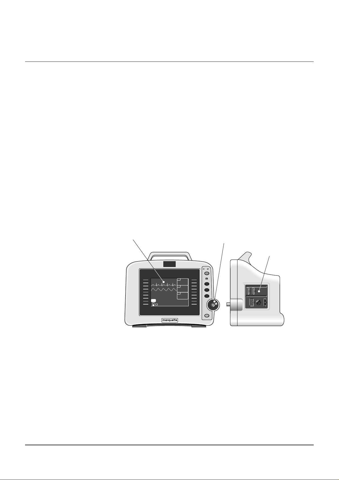
Dash 2000 Monitor
The Dash 2000 monitor is a self-contained patient transport monitor
available with a built-in writer (optional). The monitor can be viewed on a
Tramscope monitor, an Eagle 4000 monitor, a Dash 3000 monitor, a
Centralscope central station or a Clinical Information Center over the
Marquette Unity Network via Ethernet.
This device is designed to monitor a fixed set of parameters including ECG,
noninvasive blood pressure, impedance respiration, SpO2, and temperature.
Invasive pressure is an optional feature.
All of the patient cable connectors are located on the right side panel of the
monitor. The screen displays patient information in a logical, easily
understood format. A Trim Knob control provides single control operation of
virtually all monitor functions.
The monitor is available in both monochrome and color.
AC Battery
Power
Charging Status
Graph Go/Stop
NBP Go/Stop
Function
Trim Knob
Silence Alarm
Trim Knob
Control
Patient Cable
Connectors
Screen
DASH 2000
DAK.BED 1
150/ 5021-NOV-1998 16:27
ECG
II
SPO
2
MORE
MENUS
+-
75
105/ 90
SPO
2
* * *
97
RT
70
200/ 80
NBP
XXX/
ADT
001
Monitor, Front and Side Views
The illustration above shows one invasive pressure connector (labeled BP).
This is an optional feature which your monitor may not have. References
are made to this optional feature throughout the manual. Please ignore
such references if this feature was not purchased with your monitor.
1-2 Dash 2000 Patient Monitor Revision B
227 499 06 (US/E)
Page 23
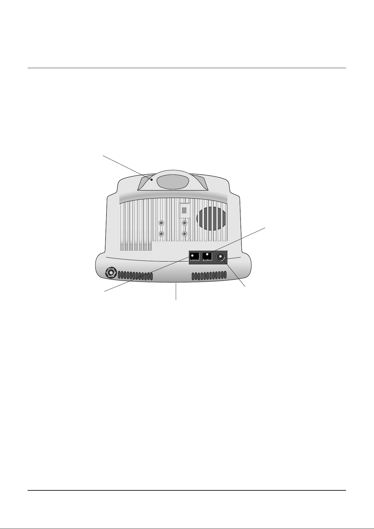
On the back of the monitor, you can find all connectors for equipment and
network. (See the illustration below.)
NOTE: Refer to the service manual for system safety requirements when
Handle – An optional alarm indicator can be
built into the handle of the monitor (not shown).
When activated, the LED indicator flashes red
for CRISIS and WARNING patient status alarms
and yellow for all other alarms.
THE BASICS: Components
connecting the monitor to accessory equipment.
Aux Port – This
auxiliary port is
non functional at
this time.
Network Connector – A cable
can be connected to this port
for monitors used in the patient
monitoring network configuration.
Power Input
Monitor, Back View
002
Defib Sync Connector – Provides ECG analog
output signals to user-supplied equipment. A 5-volt,
2-milisecond artificial pacer spike is added to the
analog output when PACE is on and detection
occurs. Refer to the Appendices, Analog Output, for
details on signal output.
Revision B Dash 2000 Patient Monitor 1-3
227 499 06 (US/E)
Page 24
THE BASICS: Components
Optional
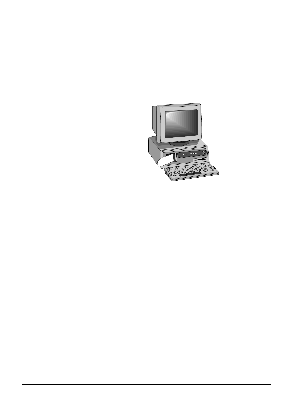
Centralscope Central
Station
The GE Marquette Unity Network (Ethernet) establishes bed-to-bed
communication and allows patient data to be sent to an optional
Centralscope central station and to other monitors on the network. All
devices must be connected to the network.
The central station may have a built-in writer for graphing (printing). This
built-in writer uses 2-inch wide graph paper.
012A
Centralscope Central Station
The Centralscope Central Station is generically referred to as the central
station throughout this manual.
Refer to the Centralscope central station operator’s manual for instructions
on operation.
1-4 Dash 2000 Patient Monitor Revision B
227 499 06 (US/E)
Page 25
THE BASICS: Components
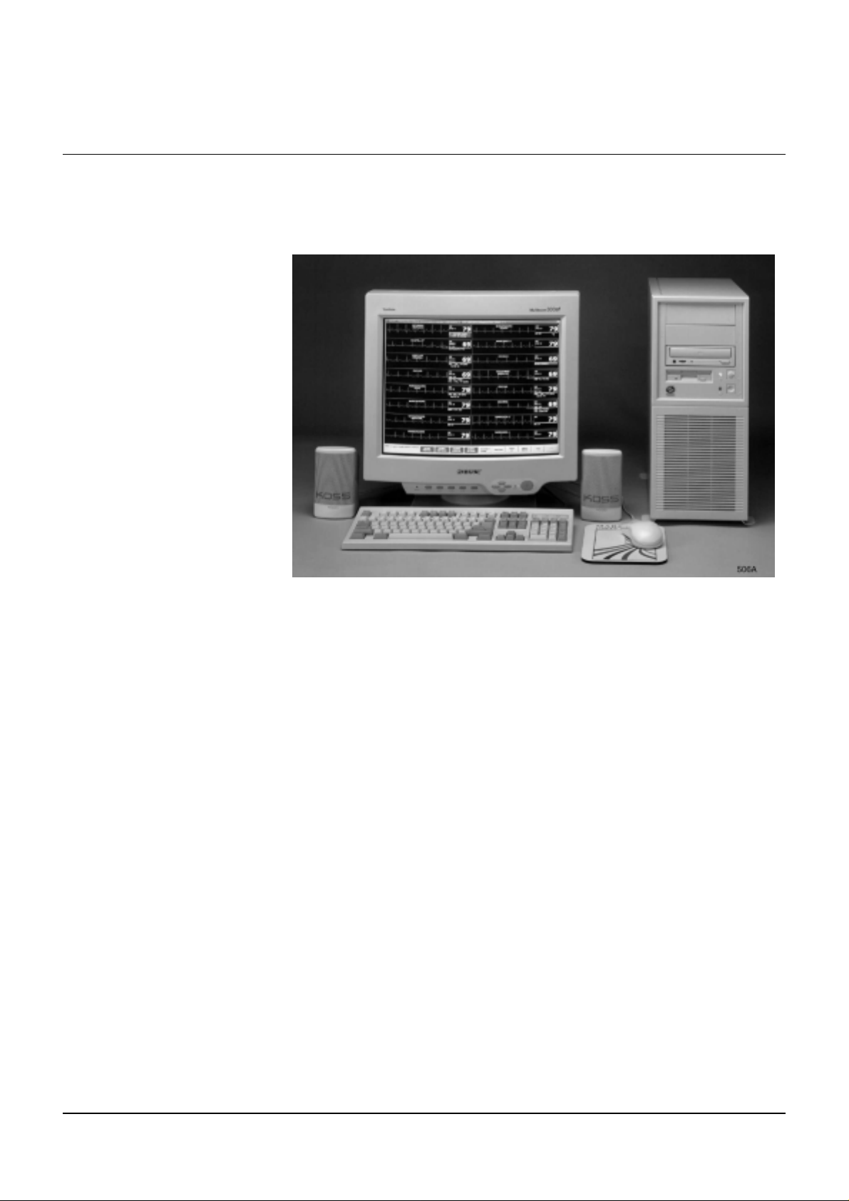
Optional Clinical
Information Center
The Unity Network (Ethernet) establishes bed-to-bed communication and
allows patient data to be sent to an optional Clinical Information Center
and to other monitors on the network. All devices must be connected to the
network.
Clinical Information Center
The Clinical Information Center is generically referred to as the central
station throughout this manual.
Refer to the Clinical Information Center operator's manual for instructions
on operation.
Revision B Dash 2000 Patient Monitor 1-5
227 499 06 (US/E)
Page 26

THE BASICS: Components
Optional Laser
Printer
An optional laser printer (not shown) connects to the central station. It is
identified on the Dash monitor as LASER when choosing a graph locat ion.
(Refer to the Monitor Setup chapter for more details.)
When you choose the laser printer as the print window location, it can print
any printable information window when it is displayed and the GRAPH GO
/ STOP key is pressed.
When you choose the laser printer as the manual graph location, it will
print the waveforms as selected in Graph Setup when the GRAPH GO /
STOP key is pressed. It prints 20 seconds of waveforms per page in a
cascade format when the graph speed is set for 25 millimeters per second.
There will be a delay of approximately one minute until the first page is
printed, then it will run until all patient data is printed.
NOTE: The one-minute delay does not mean the data printed is delayed. It
just takes that long for the information to be processed by the laser
printer. The amount of data printed will increase and the delay will
be longer if a speed slower than 25 mm/s is chosen.
When you choose the laser printer as the alarm graph location, it will
provide 20 seconds of waveforms per page in a cascade format, but again,
there will be a delay of one minute until the first page is printed.
1-6 Dash 2000 Patient Monitor Revision B
227 499 06 (US/E)
Page 27
Operation
THE BASICS: Operation
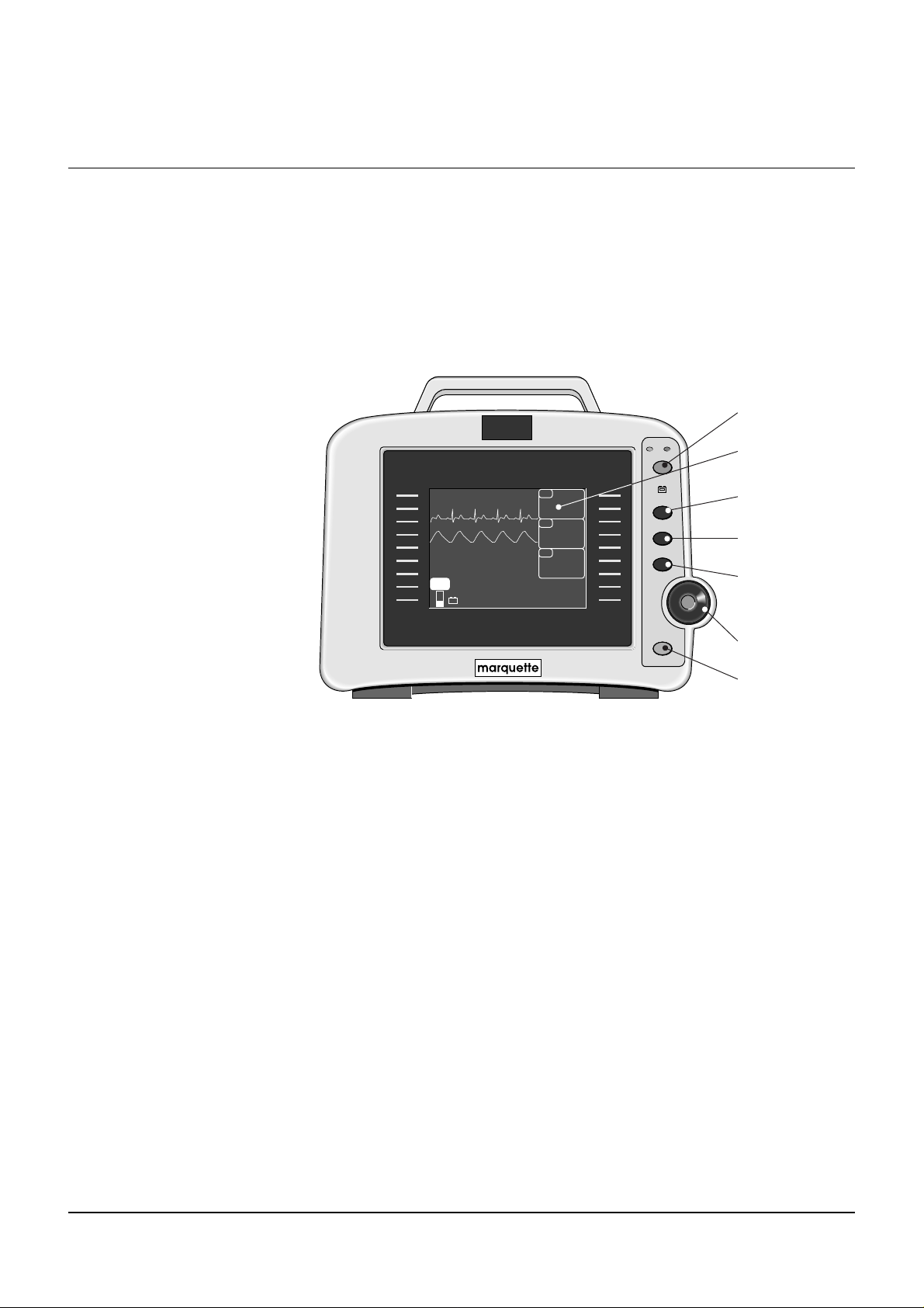
General
Below is an illustration of the front of the monitor with a waveform display.
The parts of the monitor and display which are involved in the operation of
the monitor are labeled. Each of these is described in more detail on the
following pages.
Power
Parameter
Windows
Graph
Go/Stop
NBP
Go/Stop
Function (Zero)
Trim Knob
Control
Silence Alarm
II
SPO2
MORE
MENUS
DASH 2000
AC Battery
Power
Charging Status
Graph Go/Stop
NBP Go/Stop
Function
Trim Knob
Silence Alarm
003
SPO2
* * *
RT
150/ 5021-NOV-1998 16:27
ECG
75
105/ 90
97
70
200/ 80
NBP
XXX/
ADT
DAK.BED 1
+-
Operating the Dash 2000 Patient Monitor
Revision B Dash 2000 Patient Monitor 1-7
227 499 06 (US/E)
Page 28
THE BASICS: Operation
AC Battery
Power
Graph Go/Stop
NBP Go/Stop
Function
Silence Alarm
Trim Knob
Charging Status
ECG
150/ 50
75
SPO
2
105/ 90
RT
70
* * *
97
NBP
200/ 80
ADT
XXX/
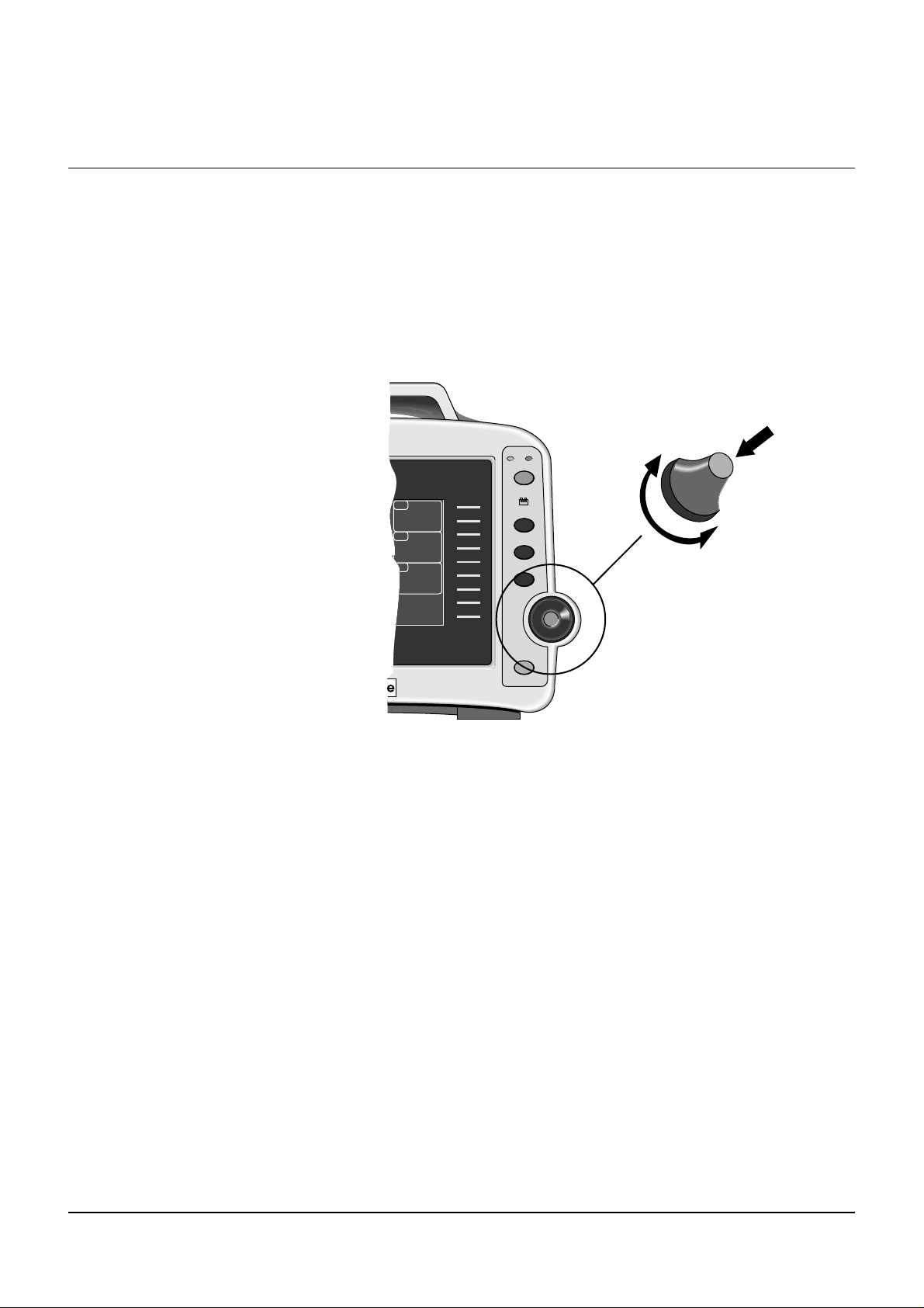
Trim Knob Control
The main operator control is the Trim Knob control. The Trim Knob control
rotates in either direction to highlight parameter labels and menu options.
After highlighting the desired selection, press the Trim Knob control to
view a new menu or a small popup menu. This procedure is referred to as
”select” throughout the manual.
Remember, when using the Trim Knob control, rotate to highlight, then
press to select.
003A
Trim Knob Control
1-8 Dash 2000 Patient Monitor Revision B
227 499 06 (US/E)
Page 29
THE BASICS: Operation
AC Battery
Power
Graph Go/Stop
NBP Go/Stop
Function
Silence Alarm
Trim Knob
Charging Status
ECG
150/ 50
75
SPO
2
105/ 90
RT
70
* * *
97
NBP
200/ 80
ADT
XXX/
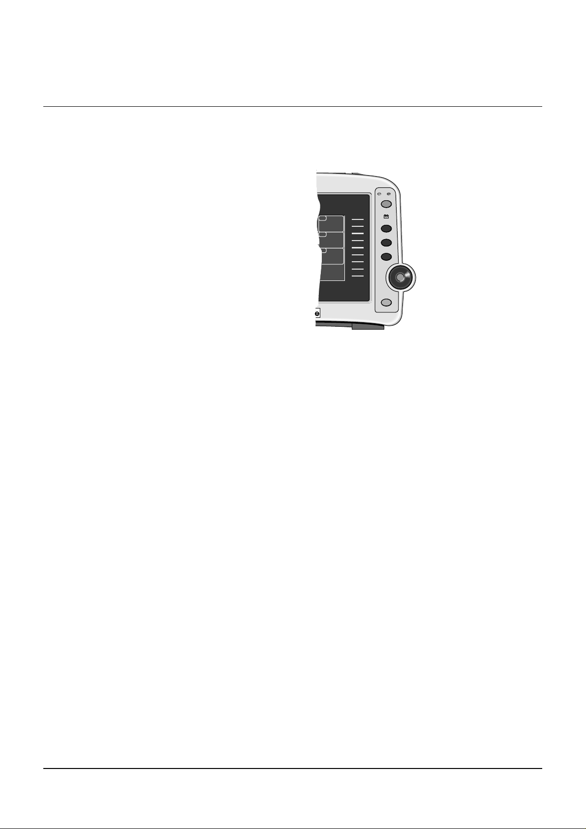
Control Keys
Power
On the right side of the monitor are five control keys. Their functions are
described below. Press the key to activate the function.
Beginning with the upper key and reading down, the keys are:
004
Location of Control Keys
The monitor will be powered at all times when plugged into AC power. This
key turns the monitoring function ON and OFF. When the monitor is
turned off, patient monitoring is discontinued; however, patient data
already accumulated is retained and the battery charging function
continues.
NOTES:To avoid unintentional switchoff, the POWER key must be pressed
at least 0.25 seconds to switch off the monitor.
In the event of a lockup, you can force a switch-off by pressing the
POWER key for five seconds.
Graph Go/Stop
Press this key once to start a graph run of the patient’s data. Press a second
time to stop. If pressed during an alarm graph run, the graph will run
continuously until GRAPH GO/STOP is pressed again. Note that an alarm
graph run is usually an automatic 20-second timed graph.
This key is also used to print a copy of non-real time screens. We refer to
these as information windows. Not all information windows can be printed.
If a printable information window is displayed, press GRAPH GO/ STOP to
print a copy. If a nonprintable information window is displayed, pressing
the GRAPH GO/STOP key prints patient data as if the information window
was not displayed.
Revision B Dash 2000 Patient Monitor 1-9
227 499 06 (US/E)
Page 30

THE BASICS: Operation
NBP Go/Stop
Function
Silence Alarm
This key starts one noninvasive blood pressure measurement. It can also be
used at any time to stop a measurement in process.
NOTE: In Operating Room Mode, if an auto mode time is set in monitor
defaults, pressing the NBP GO/STOP key starts the auto mode
feature.
This key zeroes the invasive pressure line. The pressure can also be zeroed,
if desired, with a menu option in the pressure menu. (If your monitor does
not have the invasive pressure option, this key will be present, but will not
affect the operation of the monitor.)
This key silences a current, audible alarm for 60 seconds. Only new alarms
of equal or higher level interrupt the silence command. Press the key twice
during an alarm to start an alarm pause (five minutes for Adult-ICU, 3
minutes for Neonatal-ICU). Press the key again during the alarm pause to
reactivate alarms.
If no alarm is sounding, press this key to start an alarm pause.
If your monitor is set up for Operating Room mode, you have three levels of
alarm pause:
Press once (if an alarm is sounding you must press twice) to start a 5-
•
minute alarm pause;
Press again to start a 15-minute alarm pause;
•
Press again to start a permanent alarm pause;
•
Press again to reactivate alarms.
•
1-10 Dash 2000 Patient Monitor Revision B
227 499 06 (US/E)
Page 31

Turning Power On
AC Battery
Power
Graph Go/Stop
NBP Go/Stop
Function
Silence Alarm
Trim Knob
Charging Status
ECG
150/ 50
75
SPO
2
105/ 90
RT
70
* * *
97
NBP
200/ 80
ADT
XXX/
THE BASICS: Turning Power On
AC Power
Normal Mode
Standby Mode
The Dash 2000 monitor will be powered at all times when using AC power
(there is no AC power switch). The monitor is preset at the factory for a
specific AC voltage. Before applying power, be sure the power requirements
match your power supply. Refer to the label on the back of the unit for the
voltage and current requirements. Refer also to Power Requirements in the
Safety chapter of this manual.
When all cables are properly connected, press the POWER button to turn
the monitor on. After approximately 10 seconds you should see a display on
the screen. The AC indicator on the front panel will light when using AC
power.
Two modes of operation are available when using AC power. The monitor
will enter "NORMAL" mode when plugged into AC power and the monitor
is turned ON. Normal mode operation provides all functional capabilities of
the monitor including vital signs monitoring, communications, and battery
charging.
The monitor will enter "STANDBY" mode when plugged into AC power and
the monitor is turned OFF. The battery charging function is the only
function provided when the monitor is off.
AC power indicator
005
AC Power Indicator
Revision B Dash 2000 Patient Monitor 1-11
227 499 06 (US/E)
Page 32

THE BASICS: Battery Power
Battery Power
The monitor has a built-in battery pack to provide power to the monitor
whenever AC power is interrupted. The bat tery pack is composed of ten
nickel cadmium batteries. The battery pack is generally referred to as the
”battery.”
You must charge the battery before using it. There is no external charger.
The battery is charged when the monitor is connected to AC power. A fully
depleted battery will take 1 hour when the monitor is switched off, and up
to 3 hours when the monitor is switched on, to fully charge. To assure a
fully charged battery which is ready for use, we recommend that the
monitor be plugged into AC power whenever it is not in use.
Depending on usage, you can get 2 to 3 hours of battery power on a new,
fully-charged battery on a color monitor, and up to 4 hours on a
monochrome monitor. NBP and SpO2 monitoring and the usage of the
recorder will drain battery power faster than other parameters.
NOTE: A "Battery Low" message at the top of the screen and an audible
system alarm indicate 10 minutes of battery life remaining. You
should connect the monitor to an AC power source when the
message is displayed.
1-12 Dash 2000 Patient Monitor Revision B
227 499 06 (US/E)
Page 33

THE BASICS: Battery Power
AC Battery
Power
Graph Go/Stop
NBP Go/Stop
Charging Status
Power Indicator
Lights
There are three power indicator light s on the front of the monitor. The
illustration below identifies these indicator lights.
AC Power LED
Battery Power LED
Charging status indicator
007
Power Indicator Lights
These indicators, when lit, denote a power condition. Conditions may be
designated with a single indicator or a combination of indicators. The chart
below details these power conditions and their indicators.
In the chart below, an "X" indicates that the indicator light shown at the top
of the column is lit.
Conditions Indicated by Power Indicator Lights
AC Battery Charging Status
Unit is AC
powered; battery
is being charge d
Unit is AC
powered; battery
is fully charged
Unit is battery
powered
Conditioning;
battery is being
discharged*
X yellow
X
X green
X
X
XX
* In this condition, the battery can be used but be aware it is not fully
charged so usage time is unpredictable. The system message "COND IS
RUNNING" is displayed.
NOTE: If the Charging Status LED is blinking yellow, this indicates a
malfunction in the battery management system. Please contact
Service.
Revision B Dash 2000 Patient Monitor 1-13
227 499 06 (US/E)
Page 34

THE BASICS: Battery Power
Battery Conditioning
To obtain the greatest possible battery performance and to keep the fuel
gauge up to date, the battery needs to be conditioned every 3 months or
after 250 discharge cycles.
There are three battery conditioning modes: automatic, user-controlled, and
manual.
•
automatic mode: Conditioning starts automatically when the
time limit (3 months) or the discharge limit (250 cycles) is
reached. The automatic start time for the conditioning cycle is
defined with the softkey AUTO START AT . (Should there be a
loss of AC power, all the user has to do is plug in the power
cord.)
•
user-controlled mode: If the time limit or discharge limit is
reached, the monitor displays the status message "BATTERY
NEEDS COND". It is up to the user to start the conditioning as a
result of this message.
•
manual mode: In this mode the user is required to manually
start the conditioning process. The time limit or discharge limit
is not observed and has no effect. The conditioning process is
started from the service menu.
•
In the user-controlled and manual modes, conditioning is started
using this menu sequence:
MONITOR SETUP > SERVICE MODE > BATTERY SERVICE >
START CONDITION (notify service!).
1-14 Dash 2000 Patient Monitor Revision B
227 499 06 (US/E)
Page 35

Battery
THE BASICS: Battery Power
Battery Capacity
Gauge
The battery capacity gauge or bar graph indicates the battery charge
capacity. The gauge is drawn as a vertical, rectangular outline which is
filled in from bottom to top proportional with the battery charge level.
The full rated capacity of the type of battery installed will be represented on
the gauge by a dashed outline. The maximum charge level for the cell
currently installed in the monitor is represented by a solid outline on the
gauge. As the battery ages-and its charging capacity becomes diminishedthis line becomes a smaller percentage of the full rated capacity shown by
the solid line. Refer to the following examples:
New battery,
fully charged
New battery,
approximately
60% charged
Old battery,
fully charged
Old battery, charged
to approximately
75% of its current
capacity (less than
half of its new capacity)
008
Revision B Dash 2000 Patient Monitor 1-15
227 499 06 (US/E)
Page 36

THE BASICS: Battery Power
Battery Service
Information Window
Battery Status
Messages
The Battery Service Information window can be accessed using the Trim
Knob in the Monitor Setup Æ Service Mode menu by selecting the Battery
Service softkey. The Battery Service Information window includes the
following information:
BATTERY SERVICE INFORMATION
BATTERY CAPACITY
NEW
ACTUAL FULL
ACTUAL REMAINING
FULL/NEW
REPLACE BELOW
BA TTER Y TEMPERATURE:
LAST CONDITIONING:
2000
mAh
1984
mAh
500
mAh
99
%
40
%
25.0
˚C
21-NOV-1998 16:27
009
Battery Service Information Window
The BATTERY LOW message is displayed in the STATUS MESSAGE line
and indicates 10 minutes of battery life remaining. You should connect the
monitor to an AC power source when the message is displayed.
The REPLACE BATTERY message is displayed in the STATUS MESSAGE
line if, when fully charged, the battery reaches only 40% capacity of its
design capacity for cell type.
The BATTERY NEEDS COND system message is displayed when the
battery needs to be reconditioned.
The COND IS RUNNING message is displayed while the battery is being
reconditioned.
The BATTERY DEFECTIVE message is displayed when errors have
occurred within the battery management system or the battery. The reason
of the error can be found in the error logbook (MONITOR SETUP ->
SERVICE MODE -> REVIEW ERRORS -> VIEW OUTPUT ERRORS).
Notify Service.
Environmental Issues: GE Marquette strives to produce products that
are both user safe and environmentally friendly. We sincerely believe that
our products and the production methods used to produce them, meet these
goals.
Battery Notice: This product contains a rechargeable battery. The average
life span of this type of battery is approximately three years. When
replacement becomes necessary, contact a qualified service representative
to perform the replacement.
Disposal Notice: Should this product become damaged beyond repair, or
for some reason its useful life is considered to be at an end, please observe
all local, state, and federal regulations that relate to the disposal of
products that contain lead, batteries, plastics, etc.
1-16 Dash 2000 Patient Monitor Revision B
227 499 06 (US/E)
Page 37

Software Features
THE BASICS: Software Features
Menus
Menu Timeout
A menu, like the name implies, is a selection of available options. These
options are displa yed at the bottom of the screen and are accessed with the
Trim Knob control. Some menus may have some empty spaces. These
spaces are available for future software enhancements.
There are two important menu options to note. One or both of these options
is found in every menu with the exception of the Main Menu.
MAIN MENU
This option will always take you back to the Main Menu. Use it
when you are finished making adjustments or accessing stored
information.
PREV MENU
This option allows you to back up to the previous menu when a
subordinate menu is displayed.
Think of these as escape or exit options.
The monitor automatically returns to the Main Menu (refer to the figure
below) when you have displayed another menu and have not used the Trim
Knob for 5 minutes (default time). This is a Monitor Defaults setting
(SETUP DEFAULT DISPLAY) which can be set for a longer period of time
or no timeout at all. Some menus, such as Vital Signs and trends, are not
affected by the timeout setting. You must exit them using one of the exit
options described above.
Main Menu
The Main Menu has one menu option, MORE MENUS, in the lower left
corner of the screen. With the Ma in Menu displayed, the screen shows all
monitored parameters and waveforms.
ECG
SPO
* * *
RT
51
NBP
ART
117/
RT
60
2
98
X/
ADT
59
150/ 5021-NOV-1998 16:27
105/ 90
200/ 80
S mmHg
200/ 80
S mmHg
46
73
X
X
010
II
SPO
160
ART
0
MORE
MENUS
DAK.BED 1
2
42.0/ 30.0
+-
TP
36.6
C
The Main Menu
From the Main Menu, you access a parameter menu by selecting the
appropriate parameter label, or you can access other menus (not related to
a specific parameter) by selecting the MORE MENUS option.
Revision B Dash 2000 Patient Monitor 1-17
227 499 06 (US/E)
Page 38

THE BASICS: Software Features
Parameter Menus
More Menus
Each parameter has its own menu from which to access features. Below is
an example of the ECG parameter menu.
MAIN
MENU
DISPLA Y:
LEAD II
RELEARN
ECG
SIZE
1X
QRS
VOLUME:
OFF
ECG
LIMITS
ANALYSIS
SETTINGS
011
ECG Parameter Menu
The Main Menu must be displayed to access a parameter menu.
To access a parameter menu, highlight a parameter label, for example,
ECG, and then press the Trim Knob control.
Each parameter menu is discussed in detail in the specific parameter
chapter.
In the lower left corner of the Main Menu is the MORE MENUS option.
Select this option to display the following menu.
MAIN
MENU
ALARM
CONTROL
PATIENT
DATA
ADMIT
MENU
MONITOR
SETUP
012
MORE MENUS Menu
ALARM CONTROL— This option displays a menu which allows you to
•
view and modify all alarm limits, change alarm levels, and adjust alarm
volume.
PATIENT DATA— This option displays a menu which allows you to
•
view patient data— vital sign history, and graphic trends.
ADMIT MENU— This option displays a menu to enter necessary
•
patient information and admit and discharge the patient to/from the
monitor. In OR mode, this menu item reads NEW CASE SETUP.
MONITOR SETUP— This option displays a menu which allows you to
•
set up the monitor to suit your needs— waveforms displayed, color
scheme, parameters on/off, graph setup, monitor defaults, etc. The
service menu is accessed here also.
Each of these options is covered in more detail in following chapters.
1-18 Dash 2000 Patient Monitor Revision B
227 499 06 (US/E)
Page 39

THE BASICS: Software Features
Popup Menus
Scrolling Popup
Pointer Popup
When some menu options are selected, a small menu ”pops up” around the
selected menu option. These are called popup menus. There are different
types of popup menus. Those most commonly used are described below.
Note that with all popup menus, the original menu remains on the screen
but the options are dimmed. The popup menu must be closed before you can
select other options from the origin al menu.
MAIN
MENU
DISPLA Y:
LEAD II
RELEARN
ECG
SIZE
1X
4X
2X
1X
0.5X
013
Scrolling Popup Menu
All available selections appear with the current selection highlighted. The
arrows are also highlighted indicating that the Trim Knob control can be
rotated (scrolled) to change the selection. When the Trim Knob control is
rotated, the new selection is highlighted and the change occurs immediately
on the screen so that the user can see if the selection is appropriate before
exiting the popup. Press the Trim Knob control to close the popup menu.
MAIN
MENU
ECG
FILTER
MONITORG
>
PACE 2
PACE 1
OFF
HELP
DETECT
PACE:
OFF
014
Pointer Popup Menu
All available selections appear and a pointer (>) is displayed. The arrows
are highlighted indicating that the Trim Knob control can be rotated to
move the pointer to another selection. However, before the change is
actually implemented, the Trim Knob control must be pressed. The popup
menu closes and the change is in effect.
Revision B Dash 2000 Patient Monitor 1-19
227 499 06 (US/E)
Page 40

THE BASICS: Software Features
Numeric Popup
Subordinate Menus
ECG LIMITS
RETURN
>
HR
MAIN
MENU
UNITS
BPM
LOW
50
HIGH
150
ECG
LIMITS
015
Numeric Popup Menu
The available selections are many; therefore, only the current selection is
displayed. The arrows are highlighted indicating the Trim Knob control can
be rotated. Rotating the Trim Knob control will change the displayed value
in the popup menu. Like the Pointer Popup, the change will not be in effect
until the Trim Knob control is pressed.
Whenever possible, short popup menus are displayed when selecting menu
options. In some cases, however, a whole new menu is displayed. This is a
menu within a menu, or a subordinate menu.
Many, but not all, subordinate menus have the PREV MENU option to
allow you to return to the previously displayed menu.
Following is an example of a subordinate menu:
Display the ECG Menu.
MAIN
MENU
DISPLAY:
LEAD II
RELEARN
ECG
SIZE
1X
QRS
VOLUME:
OFF
ECG
LIMITS
ANALYSIS
SETTINGS
016
ECG Parameter Menu
From the ECG Menu select ANALYSIS SETTINGS— the entire ECG
Menu is replaced with the subordinate ANALYSIS SETTINGS Menu.
MAIN
MENU
PREV
MENU
ECG
FILTER
MONITORG
QRS
WIDTH
NORMAL
LEAD
ANALYSIS:
MULTI
ARRHYTH
ON
DETECT
PACE:
OFF
017
ANALYSIS SETTINGS Menu
Select PREV MENU to redisplay the ECG Menu.
1-20 Dash 2000 Patient Monitor Revision B
227 499 06 (US/E)
Page 41

THE BASICS: Software Features
Direct Action Menu
Options
A direct action menu option, when selected, displays neither a popup menu
nor a subordinate menu. The opti on either turns a feature on or off, or
starts a processing function. For example, selecting the SMART BP: ON
option from the ART SETTINGS menu turns the Smart BP feature off. In
ON/OFF cases, the menu option reflects the current state; selecting it
switches to the other state.
MAIN
MENU
PREV
MENU
BP
FILTER
12Hz
SMART BP:
ON
PULSE
PATE:
ON
DISCONN
ALARM:
ON
CALIB
TRANSDUC
018
SMART BP: ON
MAIN
MENU
PREV
MENU
BP
FILTER
12Hz
SMART BP:
OFF
PULSE
PATE:
ON
DISCONN
ALARM:
ON
CALIB
TRANSDUC
019
SMART BP: OFF
Other direct action options start a process. For example, selecting the
RELEARN option from the ECG parameter menu tells the monitor to
immediately start to relearn the patient’s ECG rhythm. You can’t stop these
processes as they are short term and stop automatically; therefore, the
words identifying the menu option do not change as in ON/OFF actions.
Revision B Dash 2000 Patient Monitor 1-21
227 499 06 (US/E)
Page 42

THE BASICS: Software Features
Parameter Windows
Parameter windows are displayed on the far right side of the screen, and,
when necessary, across the bottom. Every monitored parameter has a
parameter window.
Each parameter window has two parts— a parameter label and digital
values. Depending on how you have set your defaults, limits and units of
measure may be displayed under the parameter label.
70
200/ 80
S mmHg
72
94
020
ART
136/
RT.
ART Parameter Window
1-22 Dash 2000 Patient Monitor Revision B
227 499 06 (US/E)
Page 43

THE BASICS: Software Features
Information Windows
Another window that is sometimes displayed on the screen is called an
information window. This large window is superimposed over the middle
left portion of the screen. The top real-time waveform is displayed as are 4
parameter windows.
Information windows are displayed when a HELP option is selected and
with certain menu options, such as LIMITS. The information window
contains instructions or other non-realtime information.
Below is an example of an information window:
2
51
X/
59
150/ 5021-NOV-1998 17:10
60
105/ 90
98
200/ 80
S mmHg
ADT
200/ 80
S mmHg
46
73
X
X
021
Real-Time
Waveforms
Information
Window
DAK.BED 1
II
VITAL SIGNS 21-NOV-1998 17:10
>
HR
ART-S
ART-D
ART-M
ART-R
SPO2-%
SPO2-R
ALARMS
MAIN
MENU
PREV
MENU
21-NOV
16:15
60
116
46
72
58
VIEW
OLDER
21-NOV
16:30
60
116
46
72
58
SELECT
PARAM
21-NOV
16:45
60
116
46
72
58
21-NOV
17:00
60
116
46
72
58
SPECIFIC
TIME
ECG
SPO
* * *
RT
NBP
ART
117/
RT
The Vital Signs Information Window
If a popup menu is displayed with the window, you must turn the Trim
Knob control to scroll to more information.
Revision B Dash 2000 Patient Monitor 1-23
227 499 06 (US/E)
Page 44

THE BASICS: Software Features
Trim Knob Control
Operation When
Setting Alarm Limits
Limits which trigger alarms for monitored parameters can be modified. You
should refer to the specific parameter chapter for details. When setting
alarm limits, the following information is helpful and applies to most
parameters:
The Trim Knob control will always increase (or decrease) the displayed
number in increments of one for the first five numbers. Thereafter, it
increases (or decreases) in increments of five. There may be situations
where the limit you wish to modify does not fall into this incremental
sequence. For example, the low heart rate limit default is 50. For your
patient, a limit of 44 is desired.
1. Open the HR LOW LIMIT popup menu. The number 50 is displayed.
2. Rotate the Trim Knob control until the number reads 45. It will follow
this sequence: 49, 48, 47, 46, 45. The next rotation will take the number
to 40 which, in this instance, is too low.
3. Close the popup menu when the number is 45 and immediately open it
again.
4. Rotate the Trim Knob control to 44. Closing the popup menu and then
reopening it allows you to reset again in increments of one.
The same principle applies when setting limits for other parameters.
1-24 Dash 2000 Patient Monitor Revision B
227 499 06 (US/E)
Page 45

Graphing (Printing)
THE BASICS: Graphing (Printing)
Devices
Manual Graphs
You can print displayed information using the Dash 2000 monitor's built-in
writer or, via the network, using an optional writer and/or an optional laser
printer. This manual refers to a DDW as a writer and a laser printer as a
printer.
The writer may be the Dash 2000 monitor's built-in writer or a stand-alone
writer connected to another monitor. Your system may include one or more
central stations. Some central stations come equipped with a built-in writer.
A writer can also be connected to the central station. The optional laser
printer always connects to a central station.
Patient waveforms and most information windows can be printed. You
choose which waveforms you want to print, to which device you want to
print, a duration time, and the speed at which manual graphs are printed.
These menu options are all found in the Graph Setup menu. Refer to the
Monitor Setup chapter for details.
Waveforms and information windows are printed when the GRAPH GO/
STOP key is pressed. The message ”GRAPHING MANUAL” or ”PRINTING
WINDOW” is displayed when a manual graph is requested. There is a
setting in the Graph Setup Menu which allows you to set a time for how
long a manual graph runs (e.g., continuous, 20 seconds, etc.).
NOTES:A one millivolt ECG signal at normal (1X) size equals 10
millimeters on the graph paper.
Exclusive Graph
Control
Alarm Graphs
All waveforms on a graph strip begin with 10 seconds of delayed
data. The header information printed with the waveforms is realtime data.
Once a manual graph is started, it can only be stopped from the same
source from which it was star ted or from the Graph Stop key on the writer.
This is to prevent two people at different sources starting a graph at the
same time, which results in one turning the graph on and the other turning
the graph off.
A graph strip is automatically printed when a Crisis or Warning alarm
occurs. An arrhythmia alarm graph will run until a normal sinus rhythm is
again detected or you manually stop the graph. Any other alarm graph runs
for 20 seconds or until you manually stop it.
NOTE: To convert an arrhythmia alarm graph to a manual graph, you
must stop the graph using the Graph Stop key on the writer and
immediately restart the graph.
In Operating Room mode and Neonatal-ICU mode, the alarm graphing
default is off, in Adult ICU mode, it is on. There is a menu option in the
Graph Setup menu (ALARM GRAPH) to turn this feature on and off. This
can be saved as a Monitor Default.
Revision B Dash 2000 Patient Monitor 1-25
227 499 06 (US/E)
Page 46

THE BASICS: Graphing (Printing)
Pressure Scales
Graphing Messages
Invasive pressures will always graph on individual scales as follows:
Displayed Scale
30 0-45 (CVP, LA, RA, ICP,PA)
40 0-45
60 0-60
100 0-90
160 0-150
200, 300 0-300
Auto 0-150 (ART, FEM, UAC, SP)
0-45 (PA, CVP, UVC, RA, LA, ICP)
Following is a list of all graphing messages and what they indicate:
SAVING— the device to which you want to print is busy or for some reason
inoperable. If it is an alarm graph, 20 seconds of data is saved until it can
print or another alarm graph occurs. The monitor only saves for print the
most recent alarm data. A manual graph is saved until you press the
GRAPH GO / STOP key or an alarm graph occurs.
GRAPHING MANUAL— a manual graph is in progress.
GRAPHING ALARM— a crisis or warning alarm has occurred. An
automatic graph is run.
PRINTING WINDOW— a manual graph of a printable information window
is in progress.
PAPER OUT—the writer/printer needs paper or a writer door is open.
Graph Scale
Graph Header
The graph header which is printed with all patient waveforms, includes:
type of graph (alarm or manual)
*alarm violation* (if any)
unit name, bed number, and patient name
date and time
patient-monitor type label (ICU has no label)
alarm volume level (%)
graph speed
lead failed (if any)
heart rate
arrhythmia call (if any and arrhythmia is on)
pace mode (if on)
arrhythmia mode (off or lethal)
ECG filter (Hz range)
values for all other monitored parameters
1-26 Dash 2000 Patient Monitor Revision B
227 499 06 (US/E)
Page 47

THE BASICS: Putting the Monitor Into Operation
Putting the Monitor Into Operation
Monitor Installation
and Connection
WARNING
Before using the monitor for the first time, please read the
information given in chapter 2 ”Safety”.
The operating position does not influence the performance of the monitor in
any way.
Choose a location which affords a n unobstructed view of the monitor
•
screen and easy access to th e operating controls.
Set up the device in a location which affords sufficient ventilation. The
•
ventilation openings of the device must not be obstructed (by external
equipment, walls or blankets, for instance). The ambient conditions
specified in the Technical Specifications chapter must be ensured at all
times.
The Dash 2000 monitor is designed to comply with the requirements of
•
IEC 60601/EN 60601.
Using the power cord supplied with the monitor, connect it to the power
•
line (the illustration on page 1-3 shows the power input). Use only the
original cord or an equivalent one.
WARNING
The Dash 2000 must be connected to a pro perly installe d p owe r
outlet with protective earth contacts only. If the installation
does not provide for a protective earth conductor, disconnect
the monitor from the power line and operate it on battery
power.
For measurements in or near the heart we recommend connecting the
•
monitor to the potential equalization system. Use the green and yellow
potential equalization cable and connect it to the pin labeled with the
symbol.
Our customer service engineers can be called in to connect the Dash
•
2000 to a central station and to the nurse-call system.
WARNING
For safety reasons, all connector s for patient cables and sensor
leads (with the exception of temperature) are designed to
prevent inadvertent disconnection, should someone pull on the
leads. Do not route cables in a way that they may present a
stumbling hazard. Do not install the monitor in a location
where it may drop on the patient. All consoles and brackets
used must have a raised edge at the front.
Revision B Dash 2000 Patient Monitor 1-27
227 499 06 (US/E)
Page 48

THE BASICS: Putting the Monitor Into Operation
Performance Check
Turn on the device with the power switch at the front. The green AC
•
ON indicator lights up (page 1-11).
The monitor display appears after approximately 10 seconds.
•
After power up and during operation the Dash 2000 runs automatic selftests. When a malfunction is detected, the monitor displays a message and a
prompt, asking whether the user wishes to continue operation.
WARNING
If this message appears during operation, it is the physician’s
responsibility to decide whether the unit is still suitable for
patient monitoring. As a general rule, monitoring with this unit
should continue only in extremely urgent cases and under the
supervision of a physician. The unit must be repaired before
being used again on a patient. If this message appears after
power up, the unit must be repaired before being used on a
patient.
WARNING
After connecting the monitor to a central station and/or nursecall system, verify the function of the alarm system. This can be
done, for instance, by temporarily changing one of the alarm
limits to initiate an alarm.
1-28 Dash 2000 Patient Monitor Revision B
227 499 06 (US/E)
Page 49

2 SAFETY
For Your Safety ................................................................................2-2
Intended Use ...............................................................................2-2
Terminology.................................................................................2-2
Monitor Safety.............................................................................2-2
Dangers........................................................................................2-2
Warnings......................................................................................2-3
Cautions.......................................................................................2-7
Notes ..........................................................................................2-10
Reference Literature ......................................................................2-10
Classifications.................................................................................2-11
Underwriters Laboratories, Inc................................................2-11
Safe Operating and Handling Conditions................................2-12
Equipment Symbols ..................................................................2-13
Revision B Dash 2000 Patient Monitor 2-1
227 499 06 (US/E)
Page 50

For Your Safety
SAFETY: For Your Safety
Intended Use
Terminology
The intended use of the monitoring system is to monitor physiologic
parameter data on adult, pediatric, and neonatal patients between all
acuity care areas.
Physiologic data includes the parameters covered in this manual. The
monitoring system is also intended to provide physiologic data over the
Unity network to clinical information systems. This information can be
displayed, trended, stored, and printed.
The terms danger, warning, and caution are used throughout this manual
to point out hazards and to designate a degree or level of seriousness.
Familiarize yourself with their definitions and significance.
Hazard is defined as a source of potential injury to a person.
DANGER indicates an imminent hazard which, if not avoided, will result
in death or serious injury.
WARNING indicates a potential hazard or unsafe practice which, if not
avoided, could result in death or serious injury.
CAUTION indicates a potential hazard or unsafe practice which, if not
avoided, could result in minor personal injury or product/property damage.
NOTE provides application tips or other useful information to assure that
you get the most from your equipment.
Monitor Safety
Dangers
The safety statements presented in this chapter refer to the equipment in
general and, in most cases, apply to all aspects of the monitor. There are
additional safety statements in the parameter chapters which are specific to
that monitored parameter.
The order in which safety sta tements are presented in no way implies order
of importance.
There are no dangers that refer to the equipment in general. Specific
"Danger" statements may be given in the respective sections of this manual.
2-2 Dash 2000 Patient Monitor Revision A
227 499 06 (US/E)
Page 51

SAFETY: For Your Safety
Warnings
WARNINGS
ACCIDENTAL SPILLS — To avoid electric shock or device
malfunction liquids must not be allowed to enter the device . If
liquids have entered a device , take it out of service and have it
checked by a service technician before it is used again.
ACCURACY — If the accuracy of any value displayed on the
monitor, central station, or printed on a graph strip is
questionable, determine the p atient's vital signs by alternative
means. Verify that all equipment is working correctly.
ALARMS — Do not rely exclusively on the audible alarm
system for patient monitoring. Adjustment of alarm volume to a
low level or off during patient monitoring may result in a
hazard to the patient. Remember that the most reliable metho d
of patient monitoring combines close perso nal surve illance w ith
correct operation of monitoring equipment.
After connecting the monitor to the central station and/or
nurse-call system, verify the function of the alarm system.
BEFORE USE — Before putting the system into operation
visually inspect all connecting cables for signs of damage.
Damaged cables and connectors must be replaced immediately.
Before using the system, the operator must verify that it is in
correct working order and operating condition.
Periodically, and whenever the integrity of the product is in
doubt, test all functions.
CABLES — Route all cables away from patient's throat to
avoid possible strangulation.
CONDUCTIVE CONNECTIONS — Extreme care must be
exercised when applying medical electrical equipment. Many
parts of the man/machine circuit are conductive, such as the
patient, connectors, electrodes, transducers. It is very
important that these conductive parts do not come into contact
with other grounded, conductive parts when connected to the
insulated patient input of the device . Such contact w ould bridg e
the patient's insulation and cancel the protection provided by
the insulated input. In particular, there must be no contact of
the neutral electrode and ground.
Revision B Dash 2000 Patient Monitor 2-3
227 499 06 (US/E)
Page 52

SAFETY: For Your Safety
WARNINGS
DEFIBRILLATION — Do not come into contact with patients
during defibrillation. Otherwise serious injury or death could
result.
DISCHARGE TO CLEAR PATIENT DATA — When admitting
a new patient, you must clear all previous patient data from the
system. To accomplish this, disconnect patient cables (if you use
a Tram module be sure the module is locked in place in the
Tram-rac housing), then do a discharge.
DISCONNECTION FROM MAINS — When disconnecting the
system from the power line, remove the plug from the wall
outlet first. Then you may disconnect the power cord from the
device. If you do not observe this sequence, there is a risk of
coming into contact with line voltage by inse rting me tal o bje cts,
such as the pins of leadwires, into the sockets of the power cord
by mistake.
DISPOSAL — Dispose of the packaging material, observing the
applicable waste control regulations and keeping it out of
children's reach.
EXPLOSION HAZARD — Do not use this equipment in the
presence of flammable anesthetics, vapors or liquids.
INTERFACING OTHER EQUIPMENT — Devices may only be
interconnected with each other or to parts of the system when it
has been determined by qualified biomedical engineering
personnel that there is no danger to the patient, the operator,
or the environment as a result. In those instances where there
is any element of doubt concerning the safety of connected
devices, the user must contact the manufacturers concerned (or
other informed experts) for proper use. In all cases, safe and
proper operation should be verified with the applicable
manufacturer's instructions for use, and system standards IEC
60601-1-1/EN 60601-1-1 must be complied with.
2-4 Dash 2000 Patient Monitor Revision B
227 499 06 (US/E)
Page 53

SAFETY: For Your Safety
WARNINGS
INTRACARDIAC APPLICATION — When applying devices
intracardially, electrically conductive contact with parts
connected to the heart (pressure transducers, metal tube
connections and stopcocks, guide wires, etc.) must be avoided in
all cases.
To prevent electrical contact, we recommend the following:
•
always wear isolating rubber gloves,
•
keep parts that are conductively connected to the heart
isolated from ground,
•
if possible, do not use tube fittings or stopcocks made of
metal.
During intracardiac application of a device, a defibrillator and
pacemaker whose proper functioning has been verified must be
kept at hand.
LEAKAGE CURRENT TEST — When interfacing with other
equipment, a test for leakage current must be performed by
qualified biomedical engineering personnel before using with
patients.
PATIENT AMBULATION — A patient must be assisted if
ambulating with a roll-stand mounted monitor.
POWER SUPPLY — The device must be connected to a
properly installed power outlet with protective earth contacts
only. If the installation does not provid e for a protective earth
conductor, disconnect the monitor from the power line and
operate it on battery power, if possible.
All devices of a system must be connected to the same power
supply circuit. Devices which are not connected to the same
circuit must be electrically isolated when oper ated (electrically
isolated RS232 interface).
PROTECTED LEADWIRES — Only use protected leadwires
and patient cables with this monitor. The use of unprotected
leadwires and patient cables creates the potential for making
an electrical connection to ground or to a high voltage power
source which can cause serious injury or death to the patient.
Unprotected Leadwire Protected Leadwire
002A
Revision B Dash 2000 Patient Monitor 2-5
227 499 06 (US/E)
Page 54

SAFETY: For Your Safety
WARNINGS
RATE METERS — Keep pacemaker patients under close
observation. Rate meters may continue to count the pacemaker
rate during cardiac arrest and some arrhythmias. Therefore, do
not rely entirely on rate meter alarms.
SITE REQUIREMENTS — For safety reasons, all connectors
for patient cables and sensor leads (with the exception of
temperature) are designed to prevent inadvertent
disconnection, should someone pull on them. Do not route
cables in a way that they may prese nt a stumbling hazard . For
devices installed above the patient, adequate pre cautions must
be taken to prevent them from dropping on the patient.
2-6 Dash 2000 Patient Monitor Revision B
227 499 06 (US/E)
Page 55

SAFETY: For Your Safety
Cautions
CAUTIONS
ACCESSORIES (SUPPLIES) — To ensure patient safety, use
only parts and accessories manufactured or recommended by
GE Marquette Medical Systems.
Parts and accessories used must meet the requirements of the
applicable IEC 60601 series safety standards and essential
performance standards, and/or the system configuration must
meet the requirements of the IEC 60601-1-1 medical electrical
systems standard.
ACCESSORIES (EQUIPMENT) — The use of ACCESSORY
equipment not complying with the equivalent safety
requirements of this equipmen t may lead to a reduced level of
safety of the resulting system. Consideration relating to the
choice shall include:
•
use of the accessory in the PATIENT VICINITY; and
•
evidence that the safety certification of the ACCESSORY
has been performed in accordance to the appropriate IEC
60601-1 and/or IEC 60601-1-1 harmonized national
standard.
BATTERY POWER — If a device equipped with an optional
battery pack will not be used or not be connected to the power
line for a period of over six months, remove the battery.
BEFORE INSTALLATION — Compatibility is critical to safe
and effective use of this device. Please contact your lo cal sales
or service representative prior to installation to verify
equipment compatibility.
DEFIBRILLATOR PRECAUTIONS — Patient signal inputs
labeled with the CF and BF symbols with paddle s are pro tected
against damage resulting from defibrillation voltages. To
ensure proper defibrillator protection, use only the
recommended cables and leadwires.
Proper placement of defibrillator paddles in relation to the
electrodes is required to ensure successful defibrillation.
Revision B Dash 2000 Patient Monitor 2-7
227 499 06 (US/E)
Page 56

SAFETY: For Your Safety
CAUTIONS
DISPOSABLES — Disposable devices are intended for single
use only. They should not be reused as performance could
degrade or contamination could occur.
DISPOSAL — At the end of its service life, the product
described in this manual, as well as its accessories, must be
disposed of in compliance with the guidelines regulating the
disposal of such products. If you have questions concerning
disposal of products, please contact GE Marquette Medical
Systems or its representatives.
ELECTROCAUTERY PRECAUTIONS — To prevent skin
burns, apply electrocautery electrodes as far as possible from
all other electrodes, a distance of at least 15 cm/6 in. is
recommended.
EMC — Magnetic and electrical fields are capable of
interfering with the proper performance of the device. For this
reason make sure that all external devices operated in the
vicinity of the monitor comply with the relevant EMC
requirements. X-ray equipment or MRI devices are a possible
source of interference as they may emit higher levels of
electromagnetic radiation. Also, keep cellular phones or other
telecommunication equipment away from the monitor.
INSTRUCTIONS FOR USE — For continued safe use of this
equipment, it is necessary that the listed instructions are
followed. Howeve r, instructions listed in this manual in no way
supersede established medical practices concerning patient
care.
LOSS OF DATA — Should the monitor at any time
temporarily lose patient data, the potential exists that active
monitoring is not being done. Close patient observation or
alternate monitoring devices should be used until monitor
function is restored.
If the monitor does not automatically resume operation w ithin
60 seconds, power cycle the monitor using the power on/off
switch. Once monitoring is restored, you should verify correct
monitoring state and alarm function.
MAINTENANCE — Regular preventive maintenance should
be carried out annually (Technical Inspections). You are
responsible for any requirements specific to your country.
2-8 Dash 2000 Patient Monitor Revision B
227 499 06 (US/E)
Page 57

SAFETY: For Your Safety
CAUTIONS
MPSO — The use of a multiple portable socket ou tlet (MPSO)
for a system will result in an enclosure leakage curre nt equal to
the sum of all individual earth leakage curre nts of the syste m if
there is an interruption of the MPSO protective earth
conductor. Do not use an additional extension cable with the
MPSO as it will increase the chance of the single protective
earth conductor interruption.
NEGLIGENCE — GE Marquette Medical Systems does not
assume responsibility for damage to the equipment caused by
improperly vented cabinets, improper or faulty power, or
insufficient wall strength to support equipment mounted on
such walls.
OPERATOR — Medical technical equipment such as this
monitor/monitoring system must only be used by persons who
have received adequate training in the use of such equipment
and who are capable of applying it properly.
POWER REQUIREMENTS — Before connecting the device to
the power line, check that the voltage and frequency ratings of
the power line are the same as those indicated on the unit's
label. If this is not the case, do not connect the system to the
power line until you adjust the unit to match the power source.
In U.S.A., if the installation of this equipment will use 240V
rather than 120V, the source must be a center-tapped, 240V,
single-phase circuit.
RESTRICTED SALE— U.S. federal law restricts this device to
sale by or on the order of a physician.
SUPERVISED USE— This equipment is intended for use under
the direct supervision of a licensed health care practitioner.
VENTILATION REQUIREMENTS— Set up the device in a
location which affords sufficient ventilation. The ventilation
openings of the device must not be obstructed. The ambient
conditions specified in the technical specifications must be
ensured at all times.
Revision B Dash 2000 Patient Monitor 2-9
227 499 06 (US/E)
Page 58

SAFETY: For Your Safety
Notes
Reference Literature
Put the monitor in a location where you can easily see the screen and
•
access the operating controls.
This product is protected against the effects of cardiac defibrillator
•
discharges to ensure proper recovery, as required by test standards.
(The screen may blank during a defibrillator discharge but recovers
within seconds as required by test standards.)
Medical Device Directive 93/42/EEC
EN 60601-1/1990 + A1: 1993 + A2: 1995: Medical electrical equipment.
General requirements for safety
EN 60601-1-1/9.1994 + A1 12.95: General requirements for safety.
Requirements for the safety of medical electrical systems.
IEC Publication 513/1994: Fundamental aspects of safety standards for
medical equipment.
ROY, O.Z.: Summary of cardiac fibrillation thresholds for 60-Hz currents
and voltages applied directly to the heart. Med. & Biol. Engn. & Computing
18: 657...659 (1980).
2-10 Dash 2000 Patient Monitor Revision B
227 499 06 (US/E)
Page 59

SAFETY: Classifications
Classifications
The Dash 2000 Patient Monitor is classified, according to IEC 60601-1 as:
Type of protection against
I
electric shock:
Degree of protection against
electric shock:
CF— ECG, Temp, Resp,
BP
BF— NBP, SpO2
Degree of protection against
harmful ingress of water:
Ordinary Equipment
(enclosed equipment
without protection
against ingress of water)
Degree of safety of
Not suitable
application in the presence
of a flammable anesthetic –
mixture with air or with
oxygen or nitrous oxide:
I: Class I equipment
CF: Type CF applied part
BF: Type BF applied part
Not suitable: Equipment not suitable for use in the presence of flammable
anesthetic mixture with air or with oxygen or nitrous oxide.
Underwriters
Laboratories, Inc.
I
S
F
S
I
E
A
L
C
Classified by Underwriters Laboratories Inc.
D
with respect to electric shock, fire, mechanical
R
CUS
and other specified hazards, only in accordance
with UL 2601-1, CAN/CSA C22.2 No. 601.1, IEC
60601-1, and, if required, IEC 60601-2-27, IEC
60601-2-30, IEC 60601-2-34, IEC 60601-1-1.
Revision B Dash 2000 Patient Monitor 2-11
227 499 06 (US/E)
Page 60

SAFETY: Classifications
Safe Operating and
Handling Conditions
Method(s) of sterilization or
disinfection recommended by
the manufacturer:
Mode of operation:
Electromagnetic interference No cordless telephone
Electrosurgical interference
damage
Diathermy instruments
influence
Defibrillation shocks The monitor specifications
Auxiliary outputs The system must fulfill the
Sterilization: not
applicable
Disinfection: see
"Maintenance -> General
Cleaning"
Continuous operation
nearby
No damage
Displayed values and prints
may be disturbed or
erroneous during diathermy.
fulfill the requirements of
EC13, IEC 60601-2-27, -30,
34 and prEN 865.
requirements of standard
IEC 60601-1-1.
2-12 Dash 2000 Patient Monitor Revision B
227 499 06 (US/E)
Page 61

SAFETY: Classifications
Equipment Symbols
NOTE: The rating of protection
against electric shock
(indicated by symbol for
CF or BF) is achieved
only when used with
patient applied parts
recommended by GE
Marquette.
NOTE
: Some symbols may not appear on all equipment.
ATTENTION: Consult accompanying docume nts
CAUTION: To reduce the risk of electri c s h ock, do NOT
remove cover. Refer servicing to qualified service personnel.
TYPE CF APPLIED PART: Insulated (floating) applied part
suitable for intentional external and internal application to
the patient including direct cardiac application. "Paddles"
outside the box indicate the applied part is defibrillator proof.
Medical Standard Definition: F-type applied part
(floating/insulated) complying with the specified requirements
of IEC 60601-1/UL 2601-1/CSA 601.1 Medical Standards to
provide a higher degree of protection against electric shock
than that provided by type BF applied parts.
TYPE BF APPLIED PART: Insulated (floating) applied part
suitable for intentional external and internal application to
the patient excluding direct cardiac application . "Paddles"
outside the box indicate the applied part is defibrillator proof.
Medical Standard Definition: F-type applied part
(floating/insulated) complying with the specified requirements
of IEC 60601-1/UL 2601-1/CSA 601.1 Medical Standards to
provide a higher degree of protection against electric shock
than that provided by type B applied parts.
TYPE B APPLIED PART: Non-insulated applied part suitable
for intentional external and internal application to the patient
excluding direct cardiac application.
Medical Standard Definition: Applied part complying with the
specified requirements of IEC 60601-1/UL 2601-1/CSA 601.1
Medical Standards to provide protection against electric shock,
particularly regarding allowable leakage current.
Fuse
Equipotentiality
Alternating current (AC)
Power; I = ON; O = OFF
Indicates where to press to open the door on the DDW.
Revision B Dash 2000 Patient Monitor 2-13
227 499 06 (US/E)
Page 62

For your notes
SAFETY: Classifications
2-14 Dash 2000 Patient Monitor Revision B
227 499 06 (US/E)
Page 63

3 ADMIT DISCHARGE
About Admitting...............................................................................3-2
You Must Admit to Activate Alarms..........................................3-2
Monitors are Used in Different Ways ........................................3-2
Guidelines When Doing Combination Monitoring...............3-3
For Which Application is the Monitor Set?................................3-3
Getting to the Admit Menu..............................................................3-4
Standard Admit Menu .....................................................................3-5
Rover Admit Menu ...........................................................................3-6
Combo Admit Menu..........................................................................3-7
Rover Combo Admit Menu...............................................................3-8
Admit Menu Options........................................................................3-9
Admit Info....................................................................................3-9
Change Admit Info...............................................................3-10
Request Admit Info..............................................................3-11
Save Admit Info....................................................................3-11
Weight and Height...............................................................3-11
Age .....................................................................................3-11
Admit Patient ............................................................................3-12
Admit Patient.......................................................................3-12
New Case ..............................................................................3-12
Set Unit Name...........................................................................3-13
Set Bed Number ........................................................................3-14
Set Graph Location ...................................................................3-14
ECG Source................................................................................3-15
About Discharging..........................................................................3-16
Discharge Patient......................................................................3-16
Standard and Rover Admit Menu.......................................3-16
Combo and Rover Combo.....................................................3-17
New Case ..............................................................................3-17
Revision B Dash 2000 Patient Monitor 3-1
227 499 06 (US/E)
Page 64

About Admitting
ADMIT DISCHARGE: About Admitting
You Must Admit to
Activate Alarms
Monitors are Used in
Different Ways
Admitting a patient to the monitor is important. Audible alarms are off
and there will be no alarm graphs and alarm history until the monitor is in
the admit mode. The following message is displayed near the middle of the
screen to alert you to admit your patient:
ALL ALARMS OFF
ADMIT PATIENT TO ACTIVATE ALARMS
What you do to admit a patient to the monitor depends on how the monitor
is used. We have defined four ways in which the monitor is used:
STANDARD— This application uses a monitor mounted in the room. It
does not accommodate telemetry. A network connection is not required
unless you have a central station.
ROVER— With this application you can move, or ”rove,” the monitor to
the patient, rather than moving the patient to a monitored room. It does
not accommodate telemetry. A network connection is not required
unless you have a central station.
COMBO— This application provides the option to acquire ECG data
from either the monitor or from a telemetry receiver cabinet. This ECG
data acquisition capability enhances basic telemetry monitoring by
providing additional access to all of the available parameters from the
monitor. A network connection is required.
ROVER COMBO— This application combines the mobility feature of
Rover monitoring with the telemetry compatibility of Combo
monitoring. A network is required.
It is determined at the time of installation which application applies. At
that time a menu option in the service mode is used to set your monitor for
one of the above applications. The information that is necessary for
successful admission to the monitor and the network is then provided in the
Admit Menu.
3-2 Dash 2000 Patient Monitor Revision B
227 499 06 (US/E)
Page 65

ADMIT DISCHARGE: About Admitting
Guidelines When
Doing Combination
Monitoring
For Which
Application is the
Monitor Set?
Here are some guidelines to remember when doing combination (Combo
and Rover Combo) monitoring:
When monitoring ECG from telemetry, ECG limits and arrhythmia
•
alarm levels are not your monitor defaults but are the telemetry
defaults or as modified at the central station. You can, however, adjust
these settings at the monitor.
When monitoring ECG from telemetry, the alarm pause feature (if
•
available on your transmitter) is honored at the monitor.
If you switch ECG monitoring from telemetry to monitor, the ECG
•
limits, arrhythmia alarm levels, and display formats will be recalled
from Monitor Defaults.
If you want to know the application for which the monitor is set, follow
these steps:
1. Select MORE MENUS option from the Main Menu.
2. Select MONITOR SETUP.
3. Select SOFTWARE SUMMARY. An information window is displayed.
(See the figure below.)
21-NOV-1998 16:27
DAK.BED 1
II
SOFTWARE SUMMARY
SOFTWARE REVISIONS
MAIN
MAIN BOOT
DAS
DAS BOOT
ETCO2
ETCO2 BOOT
DDW
ADMIT MENU:
MONITOR TYPE:
MAIN
MENU
PREV
MENU
414957-006 INT5 02OCT1998
414959-005 3B 18FEB97
415-002 2A 11JAN96
-
-
STANDARD
ADLT-ICU
MONITOR
DEFAULTS
PARAM
ON/OFF
SOFTWARE
SUMMARY
OK
022
SOFTWARE SUMMARY Information Window
Revision B Dash 2000 Patient Monitor 3-3
227 499 06 (US/E)
Page 66

ADMIT DISCHARGE: Getting to the Admit Menu
Getting to the Admit Menu
1. Select MORE MENUS from the Main Menu.
2. Select ADMIT MENU to display one of the following menus.
MAIN
MENU
ALARM
CONTROL
PATIENT
DATA
ADMIT
MENU
MONITOR
SETUP
023
Adult-ICU and Neonatal-ICU Modes
MAIN
MENU
ALARM
CONTROL
PATIENT
DATA
NEW CASE
SETUP
MONITOR
SETUP
024
Operating Room Mode
3. Select ADMIT MENU or NEW CASE SETUP to display the Admit
Menu. The admit menu displayed depends on how your monitor has
been set up. The following pages describe the various admit menus.
3-4 Dash 2000 Patient Monitor Revision B
227 499 06 (US/E)
Page 67

ADMIT DISCHARGE: Standard Admit Menu
Standard Admit Menu
With the Standard application, the monitor is permanently assigned to a
room. The unit name and bed number are assigned during installation. The
options you may need to adjust/enter are shown in the admit menu below.
MAIN
MENU
PREV.
MENU
ADMIT
INFO
XXX
PATIENT
025
ICU ADMIT Menu – STANDARD application
NOTE: XXX=ADMIT if patient is discharged, DISCHARG otherwise.
MAIN
MENU
PREV.
MENU
ADMIT
INFO
NEW
CASE
026
OR ADMIT Menu – STANDARD Application
ADMIT INFO—opens t he admit information window and popup menu;
refer to section Admit Info later in this chapter.
ADMIT PATIENT–a direct action menu option that admits the patient.
DISCHARG PATIENT—opens a popup menu to confirm the discharge of
the patient.
NEW CASE—a direct action option which discha rges the patient’s
information and, with no additional steps, readies the monitor for the next
patient (new admission).
Refer to this chapter, Admit Menu Options, if you need more details on
these menu options.
Revision B Dash 2000 Patient Monitor 3-5
227 499 06 (US/E)
Page 68

Rover Admit Menu
ADMIT DISCHARGE: Rover Admit Menu
With the Rover application, the monitor may be on a cart which allows you
to move it from one room to another. The unit name and bed number, in
some cases, may need to be changed so they are included as options in the
admit menu.
MAIN
MENU
PREV.
MENU
SET
UNIT
NAME
ADMIT
INFO
SET
BED
NUMBER
XXX
PATIENT
SET
GRAPH
LOCATION
027
ICU ADMIT Menu – Rover Application
NOTE: XXX=ADMIT if patient is discharged, DISCHARG otherwise.
MAIN
MENU
PREV.
MENU
SET
UNIT
NAME
ADMIT
INFO
SET
BED
NUMBER
NEW
CASE
SET
GRAPH
LOCATION
028
OR ADMIT Menu – Rover Application
SET UNIT NAME—verify or change the unit name. The correct unit name
is essential for recognition at a central station and other network devices.
SET BED NUMBER— verify or change the assigned bed number. The
correct bed number is essential for recognition at a central station and other
network devices.
SET GRAPH LOCATION— option displays a menu which allows you to
choose writers for alarm and manual graphs; refer to sections Monitor
Setup, Graph Setup, Set Graph Location.
ADMIT INFO—opens t he admit information window and popup menu;
refer to section Admit Info later in this chapter.
ADMIT PATIENT–a direct action menu option that admits the patient.
DISCHARG PATIENT—opens a popup menu to confirm the discharge of
the patient.
NEW CASE—a direct action option which discha rges the patient’s
information and, with no additional steps, readies the monitor for the next
patient (new admission).
Refer to this chapter, Admit Menu Options, if you need more details on
these menu options.
3-6 Dash 2000 Patient Monitor Revision B
227 499 06 (US/E)
Page 69

Combo Admit Menu
With the Combo application, the monitor is permanently assigned to a
room, and you have the ability to obtain patient ECG data from a monitor
or from a telemetry transmitter.
NOTE: A room must have network cable in order to use telemetry.
The unit name and bed number are assigned during installation. The
options you may need to adjust/enter are shown in the admit menu below.
ADMIT DISCHARGE: Combo Admit Menu
MAIN
MENU
PREV.
MENU
ECG
SOURCE:
MONITOR
ADMIT
INFO
XXX
PATIENT
029
ICU Admit Menu—Combo Application
NOTE: XXX=ADMIT if patient is discharged, DISCHARG otherwise.
NOTE: It is not likely that this application is used when the monitor is set
for Operating Room mode. However, the admit menu would look
just like this one.
ECG SOURCE— choose either the monitor or a telemetry transmitter from
which to receive the patient’s parameter data.
ADMIT INFO—opens t he admit information window and popup menu;
refer to section Admit Info later in this chapter.
ADMIT PATIENT–a direct action menu option that admits the patient.
DISCHARG PATIENT—opens a popup menu to confirm the discharge of
the patient.
Refer to this chapter, Admit Menu Options, if you need more details on
these menu options.
Revision B Dash 2000 Patient Monitor 3-7
227 499 06 (US/E)
Page 70

ADMIT DISCHARGE: Rover Combo Admit Menu
Rover Combo Admit Menu
With this application you are combining the Rover and the Combo
applications into one. The monitor may be on a cart which allows you to
move it from one room to another and ECG data can be obtained from the
monitor or from a telemetry transmitter.
NOTE: A room must have network cable in order to use telemetry.
MAIN
MENU
PREV.
MENU
ECG
SOURCE:
MONITOR
SET
UNIT
NAME
ADMIT
INFO
SET
BED
NUMBER
XXX
PATIENT
SET
GRAPH
LOCATION
030
ICU Admit Menu—Rover Combo Application
NOTE: XXX=ADMIT if patient is discharged, DISCHARG otherwise.
NOTE: It is not likely that this application is used when the monitor is set
for Operating Room mode. However, the admit menu would look
just like this one.
ECG SOURCE— choose either the monitor or a telemetry transmitter from
which to receive the patient’s parameter data.
ADMIT INFO—opens t he admit information window and popup menu;
refer to section Admit Info later in this chapter.
ADMIT PATIENT–a direct action menu option that admits the patient.
DISCHARG PATIENT—opens a popup menu to confirm the discharge of
the patient.
SET UNIT NAME—verify or change the unit name. The correct unit name
is essential for recognition at a central station and other network devices.
SET BED NUMBER— verify or change the assigned bed number. The
correct bed number is essential for recognition at a central station and other
network devices.
SET GRAPH LOCATION— display a new menu to select writers for
manual and alarm graphs.
Refer to this chapter, Admit Menu Options, if you need more details on
these menu options.
3-8 Dash 2000 Patient Monitor Revision B
227 499 06 (US/E)
Page 71

ADMIT DISCHARGE: Admit Menu Options
Admit Menu Options
Admit Info
This menu option is found in all the admit menus.
It opens the Admit Info information window and popup menu.
The Admit Info popup menu allows you to view, change, request or save
information pertinent to the monitored patient.
Below is an example of the Admit Info information window:
21-NOV-1998 16:27
II
MANUAL ADMIT INFORMATION
RETURN
>
LAST NAME
FIRST NAME
PATIENT ID
SEX
BIRTH DATE
AGE
HEIGHT
WEIGHT
DAK.BED 1
034
ADMIT INFO Information Window
The RETURN option appears after selecting CHANGE ADMIT INFO. Then
two additional items, LOCATION ID and SITE NUMBER, are accessible
when scrolling through the window (not functional in Dash 2000).
Depending on the monitor setup, different Admit Info popup menus are
displayed:
MAIN
MENU
PREV.
MENU
CHANGE
ADMIT
INFO
WEIGHT:
KG
REQUEST
ADMIT
INFO
HEIGHT:
INCHES
SAVE
ADMIT
INFO
031
ADMIT INFO Menu—Adult ICU / OR
MAIN
MENU
PREV.
MENU
CHANGE
ADMIT
INFO
WEIGHT:
KG
REQUEST
ADMIT
INFO
HEIGHT:
INCHES
SAVE
ADMIT
INFO
AGE:
DAYS
032
ADMIT INFO Menu—Neonatal ICU
Revision B Dash 2000 Patient Monitor 3-9
227 499 06 (US/E)
Page 72

ADMIT DISCHARGE: Admit Menu Options
Change Admit Info
The CHANGE ADMIT INFO option allows you to change or enter
information pertinent to the monitored patient.
1. Select CHANGE ADMIT INFO option from the Admit Info Menu. The
RETURN option and a pointer (>) are displayed in the Admit Info
information window.
21-NOV-1998 16:27
II
MANUAL ADMIT INFORMATION
RETURN
>
LAST NAME
FIRST NAME
PATIENT ID
SEX
BIRTH DATE
AGE
HEIGHT
WEIGHT
DAK.BED 1
034
CHANGE ADMIT INFO Window
2. Rotate the Trim Knob control to move the pointer (>) and scroll through
the list; press to select an item you want to change (see below).
3. When all information is entered select RETURN. A prompt appears
giving you the option to SAVE or DO NOT SAVE CHANGES. Selecting
an option will close the popup and return you to the Change Admit Info
menu.
Name: enter up to 13 characters for each name. The name (at least part if
not all) is displayed on the monitor and central station, and printed on all
graph headers.
Patient ID: enter up to 13 characters. This is important information to
enter if you have a MUSE system or a Solar Lab Access Server. If not
entered the monitor uses a default of all 9's for MUSE storage.
Sex: select male or female.
Birth Date: enter the patient's birth date. AGE is automatically calculated.
Age: automatically calculated when the birth date is entered. Age is
calculated in years for adults and weeks, days, or years for neonates (weeks
if ages is greater than 14 days but less than 2 years). If you enter an age,
the birth date is calculated with current day and month and appropriate
year.
Height, Weight: enter the patient's height and weight.
Location ID: enter the location identification for your MUSE system if you
have one (not used in current SW versi on).
Site Number: if your institution has multiple buildings, a site number may
be necessary. A Muse system may be used for site numbering (not used in
current SW version).
3-10 Dash 2000 Patient Monitor Revision B
227 499 06 (US/E)
Page 73

ADMIT DISCHARGE: Admit Menu Options
Request Admit Info
If your monitoring system includes a Lab Access Server with an interface to
hospital information, selecting this option will display patient information
that was entered. (See the figure below.) If your system does not have this
equipment, a message is displayed below the menu when you attempt to
select this option.
AUTOMATIC ADMIT INFORMATION
LAST NAME
FIRST NAME
PATIENT ID
SEX
BIRTH DATE
AGE
HEIGHT
WEIGHT
LOCATION ID
SITE NUMBER
MAIN
MENU
PREV.
MENU
CHANGE
WEIGHT:
ADMIT
INFO
KG
DAYTON
RAY
333-33-333
MALE
14 JAN 1948
50
REQUEST
ADMIT
INFO
HEIGHT:
INCHES
Name, ID, Sex, and Birth Date
come from hospital information.
Age is calculated if a birth date
has been entered.
The remaining information will
be displayed if previously
entered. If necessary you can
add to or change the information
displayed.
034A
REQUEST ADMIT INFO Information Menu
Save Admit Info
Weight and Height
Age
Verify the accuracy of any displayed information. Use the CHANGE ADMIT
INFO option if any information needs to be corrected or additional
information entered.
NOTE: If you change any information which was supplied automatically,
you may have to notify the appropriate hospital personnel.
This option is displayed only if your monitoring system includes a Lab
Access Server with an interface to hospital information. Selecting this
option will save patient information entered at bedside.
WEIGHT and HEIGHT—these options change the units of measure for
weight and height.
AGE— this option only appears when the monitor is set for Neonatal-ICU
mode. Select it to switch age between weeks, days, or years.
Revision B Dash 2000 Patient Monitor 3-11
227 499 06 (US/E)
Page 74

ADMIT DISCHARGE: Admit Menu Options
Admit Patient
Admit Patient
New Case
Depending on how your monitor is set up, you will see either ADMIT
PATIENT or NEW CASE.
This menu option is a direct action menu option which admits the patient to
the monitor. Simply select the key to admit the patient.
This menu option is found only when the monitor is set for Operating Room
mode and Standard or Rover admit menu.
It is a direct action menu option which, when selected, does both a
discharge and immediate admit.
All patient data from the previous patient is erased, the screen blanks for a
few seconds, and then the monitor is ready for the next patient.
3-12 Dash 2000 Patient Monitor Revision B
227 499 06 (US/E)
Page 75

ADMIT DISCHARGE: Admit Menu Options
Set Unit Name
This menu option is found in the Rover and Rover Combo admit menus.
The unit name is very important for sending information to central stations
and writers.
Look at the top of the display. The unit name (CCU, ICU, etc.) is displayed
on the right. Is this the unit name which identifies your unit?
The unit name appears here
II
SPO
160
ART
0
MORE
MENUS
DAK.BED 1
2
420/ 300
+-
TP
36.6
°C
ECG
SPO
* * *
RT
51
NBP
ART
117/
RT
59
60
2
98
X/
ADT
150/ 5021-NOV-1998 16:27
105/ 90
200/ 80
S mmHg
200/ 80
S mmHg
46
73
X
X
036
Location of Unit Name on the Monitor
If it is not the correct unit name follow this procedure to change it:
1. Select SET UNIT NAME option from the Admit Menu. An information
window is displayed with the available unit names.
21-NOV-1998 16:27
II
SELECT A CARE UNIT
>
RETURN
NICU
PICU
SICU
MAIN
MENU
PREV.
MENU
SET
UNIT
NAME
DAK.BED 1
XXX
PATIENT
SET
GRAPH
LOCATION
037
SET UNIT NAME Popup Menu and Information Window
2. Rotate the Trim Knob control to move the pointer (>) in front of the
correct unit name.
3. Press the Trim Knob control. The information window closes and the
new unit name appears at the top of the monitor.
NOTE: If the monitor is not on the network, a text entry popup menu will
open.
Revision B Dash 2000 Patient Monitor 3-13
227 499 06 (US/E)
Page 76

ADMIT DISCHARGE: Admit Menu Options
ECG
150/ 50
21-NOV-1998 16:27IIDAK.BED 1
60
SPO2
105/ 90
Set Bed Number
This menu option is found in Rover and Rover Combo admit menus.
Another essential element to recognize the monitor on the network is the
bed number. Look to the right of the unit name on the display. The bed
number assigned to this monitor is displayed.
Bed number appears here
038
Location of Bed Number on the Monitor
Follow this procedure to confirm that the bed number is correct:
1. Select SET BED NUMBER from the Admit Menu. A popup menu and
information window are displayed.
21-NOV-1998 16:27
II
CONFIRM BED NUMBER:
>
CREATE NEW BED
BED1
BED2
BED3
BED4
BED5
BED6
DAK.BED 1
Set Graph Location
3-14 Dash 2000 Patient Monitor Revision B
MAIN
MENU
PREV.
MENU
SET
UNIT
NAME
SET
BED
NUMBER
XXXX
039
SET BED NUMBER Popup Menu and Information Window
2. Use the Trim Knob control to move the pointer in front of the correct
bed number.
3. If the bed number you need is not listed, select CREATE NEW BED. A
text entry popup menu opens which works just like that for setting
patient name.
NOTE: If the monitor is not on the network, a text entry popup menu will
open.
This option allows you to choose writers for alarm and manual graphs; refer
to sections Monitor Setup, Graph Setup, Set Graph Location for a detailed
description.
227 499 06 (US/E)
Page 77

ADMIT DISCHARGE: Admit Menu Options
ECG Source
This menu option is found in Combo and Rover Combo admit menus.
This menu option, which is unique to those monitors which can obtain
parameter data from telemetry or the monitor, is used to tell the monitor
where to get the parameter information.
Follow this procedure:
1. Select ECG SOURCE option from the Admit Menu. A popup menu and
an information window are displayed.
21-NOV-1998 16:27
II
SELECT ECG SOURCE
>
MONITOR
331
446
447
783
MAIN
MENU
ECG
SOURCE
DAK.BED 1
PREV.
MENU
040
ECG SOURCE Popup Menu and Information Window
The information window lists the possible sources from which the
parameter data can be obtained. The transmitter numbers listed are
those transmitters assigned to the unit.
2. Rotate the Trim Knob control to move the pointer (>) in front of the
source of choice. Select MONITOR if your patient’s ECG cable is
connected to the monitor. If your patient is wearing a telemetry
transmitter, select the transmitter number that matches the one on the
back of the transmitter.
3. Press the Trim Knob control to close the popup menu and information
window.
4. Select ADMIT PATIENT to admit the transmitter. The TTX number
now appears in the ECG parameter window.
Revision B Dash 2000 Patient Monitor 3-15
227 499 06 (US/E)
Page 78

About Discharging
When it is no longer necessary to monitor a patient, a discharge procedure
must be done to clear the system of all patient data collected. Monitor
defaults are always recalled when a discharge is done. The last unit name
and bed number used are retained. Patient name is cleared.
To discharge a patient, select MORE MENUS. Depending on how your
monitor is set up, you will see one of two menu options— DISCHARG
PATIENT or NEW CASE.
ADMIT DISCHARGE: About Discharging
WARNING
DISCHARGE TO CLEAR PATIENT DATA—When admitting a
new patient, you must clear all prev ious patient data from the
system. To accomplish this, disconnect patien t cables, then do
a discharge.
Discharge Patient
Standard and Rover
Admit Menu
This menu option indicates that the patient is admitted. You select it to
discharge the patient.
To discharge a patient from the Standard and Rover admit menu follow this
procedure:
1. Select MORE MENUS.
2. Select ADMIT MENU to display the Admit Menu.
3. Select DISCHARG PATIENT option from the Admit Menu. A popup
menu opens.
MAIN
MENU
PREV.
MENU
> ADMITTED
DISCHARGE
DISCHARG
PATIENT
042A
Standard and Rover Popup Menu to Discharge
4. Disconnect all patient cables.
5. Rotate the Trim Knob control to move the pointer to DISCHARG.
6. Press the Trim Knob control. The message ”DISCHARGED” appears at
the top of the display and all data is cleared from the system.
3-16 Dash 2000 Patient Monitor Revision B
227 499 06 (US/E)
Page 79

ADMIT DISCHARGE: About Discharging
Combo and Rover
Combo
To discharge a patient from the Combo and Rover Combo admit menu
follow this procedure:
1. Select MORE MENUS.
2. Select ADMIT MENU to display the Admit Menu.
3. Select DISCHARG PATIENT to displ ay the following popup menu.
MAIN
MENU
PREV.
MENU
> RETURN
MONITOR
TELEMETRY
BOTH
DISCHARG
PATIENT
042B
Combo and Rover Combo Popup Menu to Discharge
4. Rotate the Trim Knob control to move the pointer (>) in front of:
RETURN if you do not want to discharge.
a.
MONITOR to discharge patient from monitor onl y. If ECG was from
b.
telemetry, telemetry will remain admitted, but will not be monitored
by this monitor. The central station will continue to monitor the
telemetry.
TELEMETRY to discharge patient from telemetry only. ECG will
c.
automatically switch to the monitor.
New Case
BOTH to discharge patient from telemetry and monitor. If ECG was
d.
from the monitor, BOTH will only affect the monitor.
5. Press the Trim Knob control to complete the discharge.
This menu option is displayed only when the monitor is set for Operating
Room mode and is found in Standard and Rover admit menus.
This menu option clears patient information from the monitor. With no
additional steps, the monitor is ready for the next patient (new admission).
1. Select MORE MENUS.
2. Select NEW CASE SETUP to display the Admit Menu.
3. Disconnect patient cables.
4. Select NEW CASE from the Admit Menu.
5. Press the Trim Knob control. Patient information clears and the
monitor is automatically put in the admit state, ready for the next
patient. (You will never see the ”DISCHARGED” message displayed.)
Revision B Dash 2000 Patient Monitor 3-17
227 499 06 (US/E)
Page 80

For your notes
ADMIT DISCHARGE: About Discharging
3-18 Dash 2000 Patient Monitor Revision B
227 499 06 (US/E)
Page 81

4 ALARM CONTROL
Smart Alarms ...................................................................................4-2
Alarm Structure ...............................................................................4-3
Patient Status Alarms.................................................................4-3
System Status Alarms.................................................................4-4
Controlling Audio Alarms................................................................4-5
Silencing an Alarm for One Minute...........................................4-5
Pausing Alarms...........................................................................4-5
Turning Alarm Volume Off Permanently..................................4-5
Alarm Control Menu ........................................................................4-6
All Limits.....................................................................................4-7
Viewing an All Limits Screen................................................4-7
Changing a Limit in the All Limits Screen ..........................4-8
Alarm Graph................................................................................4-9
Alarm Volume............................................................................4-10
Parameter Alarm Level ............................................................4-11
Arrhythmia Alarm Level ..........................................................4-12
Revision B Dash 2000 Patient Monitor 4-1
227 499 06 (US/E)
Page 82

Smart Alarms
ALARM CONTROL: Smart Alarms
Alarm processing is not activated until the monitor has detected valid
physiologic data from the patient. This allows you to admit a patient and
proceed with necessary patient connections without bothersome alarm
tones. If during monitoring a new parameter is added, for example, pulse
oximetry, the alarm processing for that parameter will not be active until
valid physiologic data is detected.
NOTE: To properly use the smart alarm feature, be sure to remove all
patient cables to the monitor prior to discharging. This assures
that no data is seen after a discharge.
WARNING
After an interruption of the electric power supply (e.g. for an
emergency power test) it is necessary to check whether the
alarm processing is active again and whether asystole has
occurred while the power supply was interrupted.
4-2 Dash 2000 Patient Monitor Revision B
227 499 06 (US/E)
Page 83

Alarm Structure
ALARM CONTROL: Alarm Structure
The alarm structure of the monitor is divided into two classifications:
Patient Status Alarms and
•
System Status Alarms.
•
Within each classification there are levels which correlate to how severe the
condition is that is causing the alarm. The levels and how the monitor
responds to each are described below. Patient status alarms can, in most
cases, be moved from one level to another. Refer to this chapter,
Arrhythmia Alarm Level and Parameter Alarm Level.
Patient Status Alarms
Patient status alarms are triggered by patient condition which exceeds
parameter limits, or by an arrhythmia condition. Patient status alarms
provide you the highest priority information.
The levels within the Patient Status Alarm category and how the monitor
responds to each is shown in the following chart. The chart begins with the
most critical type of alarm (Crisis) and ends with the least critical type of
alarm (Message).
NOTE: (Only for monitors without arrhythmia detection.) For patients at
risk of asystole, it is recommended to assign the HR alarm to the
“Crisis” level (when assigned to the “Warning” level the HR alarm
will clear automatically after 3 minutes in cases of continued
asystole).
Revision B Dash 2000 Patient Monitor 4-3
227 499 06 (US/E)
Page 84

ALARM CONTROL: Alarm Structure
Alarm Level: Monitor Response:
System Status
Alarms
CRISIS*
WARNING
ADVISORY
MESSAGE
*Crisis Alarm must be silenced by the user
Alarm Tone
(3, 2, or 1 beep)
Automatic
Graph
200
200
200
200
Flashing Visual Alert
200
(Text or Parameter Value)
043
Patient Status Alarms Chart
NOTE: The automatic alarm graph feature can be set on or off as a
Monitor Default. Refer to Monitor Setup chapter.
System status alarms are triggered by mechanical or electrical problems
and are of lesser priority than patient status alarms. The levels within the
System Status Alarm category and how the monitor responds to each are
shown in the following chart.
NOTE: The optional built-in handle alarm indicator is activated (flashes
yellow) when a system status alarm occurs.
Alarm Level: Monitor Response:
WARNING
ADVISORY
Warning sounds continuously. Advisory sounds only once.
Fog-horn
tone
Alarm Te xt
Alarm Te xt
Alarm Te xt
Flashing
text
044
System Status Alarms Chart
Unlike patient status alarms, system status alarms cannot be moved from
one level to another.
4-4 Dash 2000 Patient Monitor Revision B
227 499 06 (US/E)
Page 85

ALARM CONTROL: Controlling Audio Alarms
Controlling Audio Alarms
Silencing an Alarm
for One Minute
Pausing Alarms
To silence an alarm tone when it sounds, press the SILENCE ALARM key
on the front of the monitor. The current alarm will be silenced for 60
seconds and the message ”SILENCED” is displayed on the screen.
Any new alarm at an equal or greater level will sound and the silence
command is cancelled.
An alarm pause tells the monitor that you do not want any alarms to sound
for several minutes (see below).
To start an alarm pause, press the SILENCE ALARM key on the front of
the monitor. Press the key twice if an alarm is sounding when you want to
start an alarm pause.
ADULT-ICU mode:
If your monitor is set up for this mode, a five-minute alarm pause occurs
and a count-down timer is displayed on the screen. Press the SILENCE
ALARM key again to reactivate alarms before the five- minute period
elapses.
NEONATAL-ICU mode:
If your monitor is set up for this mode, a three-minute alarm pause
occurs with a count-down timer displayed. Press the SILENCE ALARM
key again to reactivate alarms before the three-minute period elapses.
Turning Alarm
Volume Off
Permanently
OPERATING ROOM mode:
If your monitor is set up for this mode, press the key once for a 5minute pause, press again for a 15-minute alarm pause, press again for
a permanent alarm pause (message will read ”ALARMS PAUSED”).
Also arrhythmia is switched off and the alarm limits are set to the
Operating Room factory defaults.
Press the SILENCE ALARM key again to turn alarms back on.
Refer to this chapter, Alarm Volume, for a procedure whereby you can
permanently turn the alarm volume off.
Revision B Dash 2000 Patient Monitor 4-5
227 499 06 (US/E)
Page 86

Alarm Control Menu
Follow these steps to access the Alarm Control Menu:
1. Select MORE MENUS from the Main Menu.
2. Select ALARM CONTROL to display the Alarm Control Menu.
ALARM CONTROL: Alarm Control Menu
MAIN
MENU
PREV.
MENU
ALL
LIMITS
PARAM.
ALARM
LEVEL
ALARM
GRAPH:
OFF
ARRHYTH
ALARM
LEVEL
ALARM
VOL:
OFF
045
ALARM CONTROL Menu
ALL LIMITS— view a screen of all currently monitored parameters and
•
their alarm limits. Included also is the unit of measure for each. Alarm
limits can also be changed.
ALARM GRAPH— turn automatic alarm graphing on and off.
•
ALARM VOL— adjust the volume of the alarm tone.
•
PARAM. ALARM LEVEL— view parameter alarm levels. Can adjust
•
parameter alarms to other alarm levels.
ARRHYTH ALARM LEVEL— view arrhythmia alarm levels. Can
•
adjust arrhythmia alarms to other alarm levels.
4-6 Dash 2000 Patient Monitor Revision B
227 499 06 (US/E)
Page 87

ALARM CONTROL: Alarm Control Menu
All Limits
Viewing an All Limits
Screen
The ALL LIMITS menu option allows you to view the high and low alarm
limits and unit of measurement for each parameter currently monitored.
You can change the limits for any monitored parameter without having to
go into each individual parameter menu.
1. Select ALL LIMITS option from the Alarm Control Menu.
2. An information window is displayed on the screen and a popup menu is
displayed in the menu area.
21-NOV-1998 16:27
II
SETUP DEFAULT LIMITS
>
RETURN
HR
SPO2
RR
RR-APNEA
NBP-S
NBP-D
NBP-M
TP
MAIN
MENU
UNITS
BPM
%
#/MIN
SEC
mmHg
mmHg
mmHg
˚C
ALL
LIMITS
LOW
50
90
5
80
20
40
30.0
DAK.BED 1
HIGH
150
105
55
20
200
120
140
42.0
PREV.
MENU
046
ALL LIMITS Popup Menu and Information Window
The information window shows a list of the patient parameters currently
monitored, the units by which they are measured, and the high and low
limits currently in effect.
Revision B Dash 2000 Patient Monitor 4-7
227 499 06 (US/E)
Page 88

ALARM CONTROL: Alarm Control Menu
Changing a Limit in the
All Limits Screen
If you want to change one or more limits, follow the procedure below. Any
changes made with this menu option are temporary and will revert to
defaults upon discharge.
1. Rotate the Trim Knob control to move the pointer (>).
2. When the pointer is in front of the parameter you wish to change, press
the Trim Knob control. The parameter label highlights.
3. Rotate the Trim Knob control to highlight the low or high limit.
4. Press, then rotate the Trim Knob control to change the limit value.
5. Press the Trim Knob control again to complete the change. The new
limit is in effect immediately.
6. Rotate the Trim Knob control to highlight the parameter label, then
press to unhighlight. You can now move to another parameter if you
want.
7. When finished with all changes, move the pointer to RETURN, and
press the Trim Knob control to close the All Limits information window.
4-8 Dash 2000 Patient Monitor Revision B
227 499 06 (US/E)
Page 89

ALARM CONTROL: Alarm Control Menu
Alarm Graph
To adjust the automatic alarm graphing to on or off, follow this procedure:
1. Select ALARM GRAPH option from the Alarm Control Menu.
2. Pressing the Trim Knob control alternately changes the state to on or
off; the actual setting is always displayed.
Any change made with this menu option is only temporary and will revert
to default upon discharge.
Revision B Dash 2000 Patient Monitor 4-9
227 499 06 (US/E)
Page 90

ALARM CONTROL: Alarm Control Menu
Alarm Volume
To adjust the volume of the alarm tones, follow this procedure:
1. Select ALARM VOL option from the Alarm Control Menu.
2. A popup menu opens displaying all choices.
MAIN
MENU
PREV.
MENU
100 %
90 %
80 %
70 %
60 %
50 %
40 %
30 %
20 %
10 %
OFF
ALARM
VOL:
OFF
049
ALARM VOL Popup Menu
3. Rotate the Trim Knob control to change the selection. Each time the
control is rotated, you hear a tone at that volume. ALARM VOL. OFF
message is displayed at the top of the screen if OFF is selected.
NOTE: When in Neonatal-ICU mode, alarm volume cannot be turned off.
The lowest it can be set is 30%.
4. When you are satisfied with the volume level, press the Trim Knob
control to close the popup menu.
Any change made with this menu option is only temporary and will revert
to default upon discharge.
4-10 Dash 2000 Patient Monitor Revision B
227 499 06 (US/E)
Page 91

ALARM CONTROL: Alarm Control Menu
Parameter Alarm
Level
Parameter alarms are assigned to one of the four patient status alarm
categories. The PARAMETER ALARM LEVEL option allows you to view
and reassign parameter alarms to other levels.
NOTE: The heart rate limit alarm level cannot be set to the MESSAGE
level in Neonatal ICU mode.
If you want to move a parameter alarm to another level, use the PARAM
ALARM LEVEL option, and follow the same procedure as described for
arrhythmia alarm levels. Any changes made with this menu option are
temporary and will revert to defaults upon discharge.
21-NOV-1998 16:27
II
PARAMETER ALARM LEVELS
>
RETURN
HR
SPO2
RR
RR-APNEA
SPO2-RATE
NBP
TP
WARNING
ADVISORY
ADVISORY
ADVISORY
MESSAGE
MESSAGE
MESSAGE
DAK.BED 1
The parameters listed are
only those currently being
monitored.
MAIN
MENU
PREV.
MENU
PARAM.
ALARM
LEVEL
048
PARAMETER ALARM LEVELS Popup Menu and
Information Window
Revision B Dash 2000 Patient Monitor 4-11
227 499 06 (US/E)
Page 92

ALARM CONTROL: Alarm Control Menu
Arrhythmia Alarm
Level
The arrhythmia calls recognized by the monitor are assigned to one of the
four patient status alarm categories. The ARRHYTHMIA ALARM LEVEL
options allow you to view and reassign parameter alarms to other levels.
Follow this procedure to display a list of the arrhythmia calls and the alarm
level to which each is assigned:
1. Select ARRHYTH ALARM LEVEL option from the ALARM CONTROL
Menu.
2. An information window is displayed on the screen and a popup menu is
displayed in the menu area.
21-NOV-1998 16:27
II
ARRHYTHMIA ALARM LEVELS
>
RETURN
ASYSTOLE
VFIB/VTAC
V T A CH
BRADY
CRISIS
CRISIS
CRISIS
CRISIS
DAK.BED 1
MAIN
MENU
PREV .
MENU
ARRHYTH
ALARM
LEVELS
047
ARRHYTHMIA ALARM LEVELS Popup Menu & NRT
The information window shows a list of the arrhythmia calls on the left with
their corresponding alarm level to the right.
NOTE: V TACH is only found in the Adult mode and Operating Room
mode menu, BRADY is only found in the Neonatal mode menu.
4-12 Dash 2000 Patient Monitor Revision B
227 499 06 (US/E)
Page 93

ALARM CONTROL: Alarm Control Menu
If you want to move a call to another level, follow this procedure. (In this
example we will change V TACH from a Crisis level to a Warning level.)
Any changes made with this menu option are temporary and will revert to
defaults upon discharge.
NOTE: Aystole and ventricular fibrillation (V FIB, VTAC) cannot be
moved when in ICU (Adult and Neonatal) Mode.
1. Rotate the Trim Knob control to move the pointer in front of V TACH.
2. Press the Trim Knob control. The level for the V TACH call highlights.
3. Rotate the Trim Knob control until WARNING is displayed.
4. Press the Trim Knob control to complete the change. The information
window is reorganized to include V TACH as a WARNING alarm and
the change is in effect.
The information window remains open for you to make any other
changes.
5. When you have completed all changes, move the pointer to RETURN
and press the Trim Knob control to close the information window.
Revision B Dash 2000 Patient Monitor 4-13
227 499 06 (US/E)
Page 94

For your notes
ALARM CONTROL: Alarm Control Menu
4-14 Dash 2000 Patient Monitor Revision B
227 499 06 (US/E)
Page 95

5 MONITOR SETUP
Monitor Setup Menu ........................................................................5-2
Monitor Defaults .........................................................................5-3
Monitor Defaults Menu...............................................................5-3
Setup Default Arrhythmia Alarm Levels .............................5-4
Setup Default Parameter Alarm Levels ...............................5-6
Setup Default Limits..............................................................5-7
Setup Default Display............................................................5-8
Setup Default Parameter Priority.........................................5-9
Recall Default.......................................................................5-10
Display Setup Menu..................................................................5-11
Waveform On / Off ...............................................................5-12
Contrast................................................................................5-13
Color .....................................................................................5-14
Backgrnd...............................................................................5-14
Time and Date......................................................................5-14
Set Date ................................................................................5-15
Set Time................................................................................5-15
Graph Setup ..............................................................................5-16
ECG 1, Waveform 2, Waveform 3 .......................................5-17
Graph Location.....................................................................5-18
Alarm Graph.........................................................................5-20
Speed.....................................................................................5-20
Timed Graph ........................................................................5-21
Parameters On / Off ..................................................................5-22
Software Summary....................................................................5-23
Service Mode..............................................................................5-24
Patient Monitor Type...........................................................5-25
Admit Mode ..........................................................................5-25
Revision B Dash 2000 Patient Monitor 5-1
227 499 06 (US/E)
Page 96

Monitor Setup Menu
Whenever possible, we want you to be able to customize your monitor to
best suit your unit’s and patients’ needs. The Monitor Setup menu allows
you to make changes and, in some cases, to save these changes as monitor
defaults to be recalled each time you discharge a patient.
Follow this procedure to access the Monitor Setup Menu:
1. Select MORE MENUS from the Main Menu.
2. Select MONITOR SETUP to display the Monitor Setup Menu.
MONITOR SETUP: Monitor Setup Menu
MAIN
MENU
PREV.
MENU
MONITOR
DEFAULTS
PARAM.
ON / OFF
DISPLAY
SETUP
SOFTWARE
SUMMARY
GRAPH
SETUP
SERVICE
MODE
050
MONITOR SETUP Menu
MONITOR DEFAULTS— configure alarms, set alarm limits, and
•
establish display defaults to be recalled whenever a discharge is
performed.
DISPLAY SETUP selects the DISPLAY SETUP menu for the following
•
adjustments:
WAVEFORM ON / OFF— reassign waveform positions on the
•
screen or turn some waveforms off.
COLOR— choose a color configuration if you have a color monitor.
•
BACKGRND— switch from background white to black (monochrome
•
option).
CONTRAST— control how bright the display is.
•
GRAPH SETUP— select waveforms to be graphed, graph speed, and
•
where a graph will be printed.
PARAM. ON / OFF—clear unneeded parameter windows from the
•
display and turn them back on again when needed.
SOFTWARE SUMMARY— display a list of the software revisions
•
currently installed for the various components of the monitor.
SERVICE MODE— access a service mode (for qualified service
•
personnel).
Detailed information on each option is found in this chapter.
5-2 Dash 2000 Patient Monitor Revision B
227 499 06 (US/E)
Page 97

MONITOR SETUP: Monitor Setup Menu
Monitor Defaults
Monitor Defaults
Menu
Alarm levels, alarm limits, and many of your monitor settings can be set up
as Monitor Defaults. Monitor Defaults are recalled whenever a discharge
procedure is performed.
The monitor can save only one set of defaults. Whenever the monitor mode
is changed, (Adult-ICU, Neonatal-ICU, Operating Room) any Monitor
Defaults you have set up will revert to factory default settings. The monitor
mode, however, is usually established at the time of installation and can
only be changed in the service menu.
To display the menu to set up your Monitor Defaults, select MONITOR
DEFAULTS from the Monitor Setup Menu.
MAIN
MENU
PREV.
MENU
SETUP
DEFAULT
DISPLAY
PARAM.
ALARM
LEVELS
PARAM.
PRIORITY
ARRHYTH
ALARM
LEVELS
DEFAULT
LIMITS
RECALL
DEFAULT
063
MONITOR DEFAULTS Menu
NOTE: Monitor Defaults can only be changed when the monitor is in a
discharged state. Changes made are in effect immediately but
admit must be done for fully functional alarms.
SETUP DEFAULT DISPLAY— determine display settings, such as
•
Smart BP on, color format, waveforms graphed, etc.
PARAM. PRIORITY— determine the priorities you want for display of
•
parameters.
DEFAULT LIMITS— set alarm limits for all parameters.
•
PARAM. ALARM LEVELS— adjust parameter alarm levels to other
•
alarm levels.
ARRHYTH. ALARM LEVELS— adjust arrhythmia alarms to other
•
alarm levels.
RECALL DEFAULT— recall Monitor Defaults without performing a
•
discharge procedure.
Revision B Dash 2000 Patient Monitor 5-3
227 499 06 (US/E)
Page 98

MONITOR SETUP: Monitor Setup Menu
Setup Default
Arrhythmia Alarm
Levels
The arrhythmia calls recognized by the monitor are assigned to one of the
four patient status alarm levels. ARRHYTH ALARM LEVELS option
allows you to view the levels assigned as defaults to the arrhythmia calls.
Follow this procedure to display a list of arrhythmia calls and the alarm
level to which each is assigned:
1. Select ARRHYTH ALARM LEVELS option from the Monitor Defaults
Menu.
21-NOV-1998 16:27
II
ARRHYTHMIA ALARM LEVELS
>
RETURN
ASYSTOLE
V FIB/VTAC
V T A CH
MAIN
MENU
PREV .
MENU
CRISIS
CRISIS
CRISIS
ARRHYTH
ALARM
LEVELS
DAK.BED 1
064
SETUP DEFAULT ARRHYTHMIA ALARM LEVELS Popup Menu and
Information Window
The information window shows a list of the arrhythmia calls on the left
with their corresponding alarm level to the right.
NOTE: VTACH is only found in the Adult ICU and Operating Room mode,
BRADY is only found in the Neonatal ICU mode (see also page 4-6,
Alarm Control Menu).
5-4 Dash 2000 Patient Monitor Revision B
227 499 06 (US/E)
Page 99

MONITOR SETUP: Monitor Setup Menu
If you want to move an arrhythmia call to another level for your Monitor
Default, follow this procedure. (In this example we will change V TACH
from a Crisis to a Warning level.)
NOTE: Asystole and VFIB/VTAC can only be moved when in Operating
Room Mode.
1. Rotate the Trim Knob control to move the pointer (>) up and down the
list. Stop when the pointer is in front of V TACH.
2. Press the Trim Knob control. Notice that the level for the V TACH call
is highlighted.
3. Rotate the Trim Knob control until WARNING is displayed.
4. Press the Trim Knob control to complete the change. The information
window is reorganized to include V TACH as a WARNING alarm.
The information window remains open for you to make any other
changes.
5. When you have completed all changes, move the pointer to RETURN
and press the Trim Knob control to close the information window.
Revision B Dash 2000 Patient Monitor 5-5
227 499 06 (US/E)
Page 100

MONITOR SETUP: Monitor Setup Menu
Setup Default
Parameter Alarm
Levels
You can set default alarm levels for all parameters supported by the
monitor.
Use the PARAM ALARM LEVELS option to view and adjust default alarm
levels for parameters. Follow the same procedure as described for changing
arrhythmia alarm level defaults.
21-NOV-1998 16:27
II
PARAMETER ALARM LEVELS
>
RETURN
HR
SPO2
RR
RR-APNEA
SPO2-RATE
NBP
TP
MAIN
MENU
PREV.
MENU
PARAM.
ALARM
LEVELS
WARNING
ADVISORY
ADVISORY
ADVISORY
MESSAGE
MESSAGE
MESSAGE
DAK.BED 1
065
PARAM ALARM LEVELS Popup Menu and Information Window
5-6 Dash 2000 Patient Monitor Revision B
227 499 06 (US/E)
 Loading...