

GE CSA1201RSS03, CSA1201RSS04, CSA1201RSS05, ZSA1201J1SS, ZSA1201J2SS Installation Guide
...Page 1
I
stall ti
Above the
structi
I
CooktopOven
PSA1200,PSA1201,PSA2200,PSA2201,
ZSA1201,ZSA1202,ZSA2201 & CSA1201
i Questions? Call 800.GE.CARES (800.432.2737) orvisitourWebsiteat:GEAppliances.com i
BEFORE YOU BEGIN
Read these instructions completely and carefully.
Note to Consumer - Keepthese instructions
for future reference.
. IMPORTANT -Sovethese
instructionsforlocolinspector'suse.
.IMPORTANT - Observeoll
governingcodesond ordinonces.
. Note to Installer - Be sure to leove these
instructions with the Consumer.
Skill level - Installation of this appliance requires basic
mechanical and electrical skills.
e
Proper instollation is the responsibility of the instoller.
e
Product failure due to improper installation is not
covered under the Warranty.
LA SECCION EN ESPAOOL EMPIEZA
EN LA P.GINA 25.
READ CAREFULLY.
KEEP THESE INSTRUCTIONS.
Page 2
Installation Instructions
CONTENTS
General information
Important Safety Instructions ........................................ 3
Electrical Requirements .................................................. 3
Hood Exhaust ................................................................ 4, 5
Damage - Shipment/installation .................................. 6
Parts Included ................................................................... 6
Tools You Will Need ......................................................... 7
Mounting Space ................................................................ 7
Step-by-step installation guide
Placement of Mounting Plate .................................. 8-10
Removing the Mounting Plate ............................. 8
Finding the Wall Studs .......................................... 8
Determining Wall Plate Location ........................ 9
[_ Recirculating ................................................. 19-22
Attach Mounting Plate to Wall ................ 19
Preparation of Top Cabinet ...................... 19
Adapting Blower
for Recirculation .................................. 20, 21
Mount the Oven ................................... 21, 22
Installing the Charcoal Filter .................... 22
Before You Use Your Oven .......................................... 23
SecciUn en Espa(bol ................................................ 25-47
Aligning the Wall Plate ....................................... 10
Installation Types .................................................... 11-22
[_ Outside Top ....................................
[_ Outside .................................. 15-18
Exhaust 12-14
Attach Mounting Plate to Wall ................. 12
Preparation of Top Cabinet ....................... 13
Assemble and Install Adaptor .................. 13
Mount the Oven ................................... 13, 18
Adjust the Exhaust Adaptor ...................... 18
Connecting Ductwork ................................ 14
Back Exhaust
Preparing Rear Wall for
Outside Back Exhaust ................................ 15
Attach Mounting Plate to Wall .......... 15, 16
Preparation of Top Cabinet ....................... 16
Adapting Blower for Outside
Back Exhaust .......................................... 16, 17
Mount the Oven .......................................... 18
Page 3
Installation Instructions
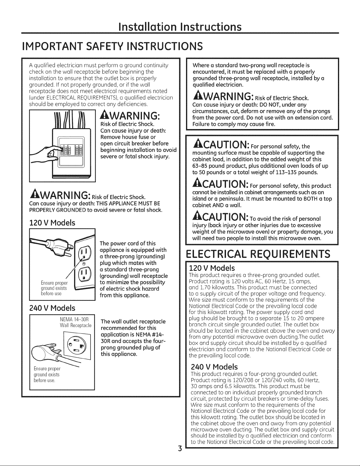
IMPORTANT SAFETY INSTRUCTIONS
A qualified electrician must perform a ground continuity
check on the wall receptacle before beginning the
installation to ensure that the outlet box is properly
grounded. If not properly grounded, or if the wall
receptacle does not meet electrical requirements noted
(under ELECTRICALREQUIREMENTS),a qualified electrician
should be employed to correct any deficiencies.
AWARNING:
Riskof Electric Shock.
Can cause injury or death:
Remove house fuse or
open circuit breaker before
beginning installation to avoid
severe or fatal shock injury.
_VV#'_|_I i |_111J:Riskof Electric Shock.
Can cause injury or death: THIS APPLIANCEMUSTBE
PROPERLYGROUNDEDto avoid severe or fatal shock.
120 V Models
The power cord of this
appliance isequipped with
a three-prong (grounding}
plug which mates with
a standard three-prong
(grounding} wall receptacle
to minimize the possibility
beforeuse
240 V Models
NEMA14-30R
WallReceptacle
of electric shock hazard
from this appliance.
The wall outlet receptacle
recommended for this
application is NEMA#14-
30R and accepts the four-
prong grounded plug of
this appliance.
Where a standard two-prong wall receptacle is
encountered, it must be replaced with aproperly
grounded three-prong wall receptacle, installed by a
qualified electrician.
AWA RNING:RiskofElectricShock.
Can cause injury or death: DO NOT,under any
circumstances, cut, deform or remove any of the prongs
from the power cord. Do not use with an extension cord.
Failure to comply may cause fire.
_!_,/=_U||U|_: For personal safety, the
mounting surface must be capable of supporting the
cabinet load, in addition to the added weight of this
63-85 pound product, plus additional oven loads of up
to 50 pounds or a total weight of 113-135 pounds.
ACAUTION: Forpersonalsafety,thisproduct
cannot be installed in cabinet arrangements such as an
island or a peninsula. It must be mounted to BOTHa top
cabinet AND a wall.
A CAUTION: Toavoidtheriskofpersonal
injury (back injury or other injuries due to excessive
weight of the microwave oven} or property damage, you
will need two people to install this microwave oven.
ELECTRICAL REQUIREMENTS
120 V Models
This product requires a three-prong grounded outlet.
Product rating is 120 volts AC, 60 Hertz, 15 amps,
and 1.70 kilowatts. This product must be connected
to a supply circuit of the proper voltage and frequency.
Wire size must conform to the requirements of the
National Electrical Code or the prevailing local code
for this kilowatt rating. The power supply cord and
plug should be brought to a separate 15 to 20 ampere
branch circuit single grounded outlet. The outlet box
should be located in the cabinet above the oven and away
from any potential microwave oven ducting.The outlet
box and supply circuit should be installed by a qualified
electrician and conform to the National Electrical Code or
the prevailing local code.
Ensureproper
groundexists
beforeuse.
240 V Models
This product requires a four-prong grounded outlet.
Product rating is 120/208 or 120/240 volts, 60 Hertz,
30 amps and 6.5 kilowatts. This product must be
connected to an individual properly grounded branch
circuit, protected by circuit breakers or time-delay fuses.
Wire size must conform to the requirements of the
National Electrical Code or the prevailing local code for
this kilowatt rating. The outlet box should be located in
the cabinet above the oven and away from any potential
microwave oven ducting. The outlet box and supply circuit
should be installed by a qualified electrician and conform
to the National Electrical Code or the prevailing local code.
3
Page 4
Installation Instructions
HOOD EXHAUST
NOTE:Read these next two pages only if you plan to vent your exhaust to the outside.
If you plan to redrculate the air back into the room, proceed to page 6.
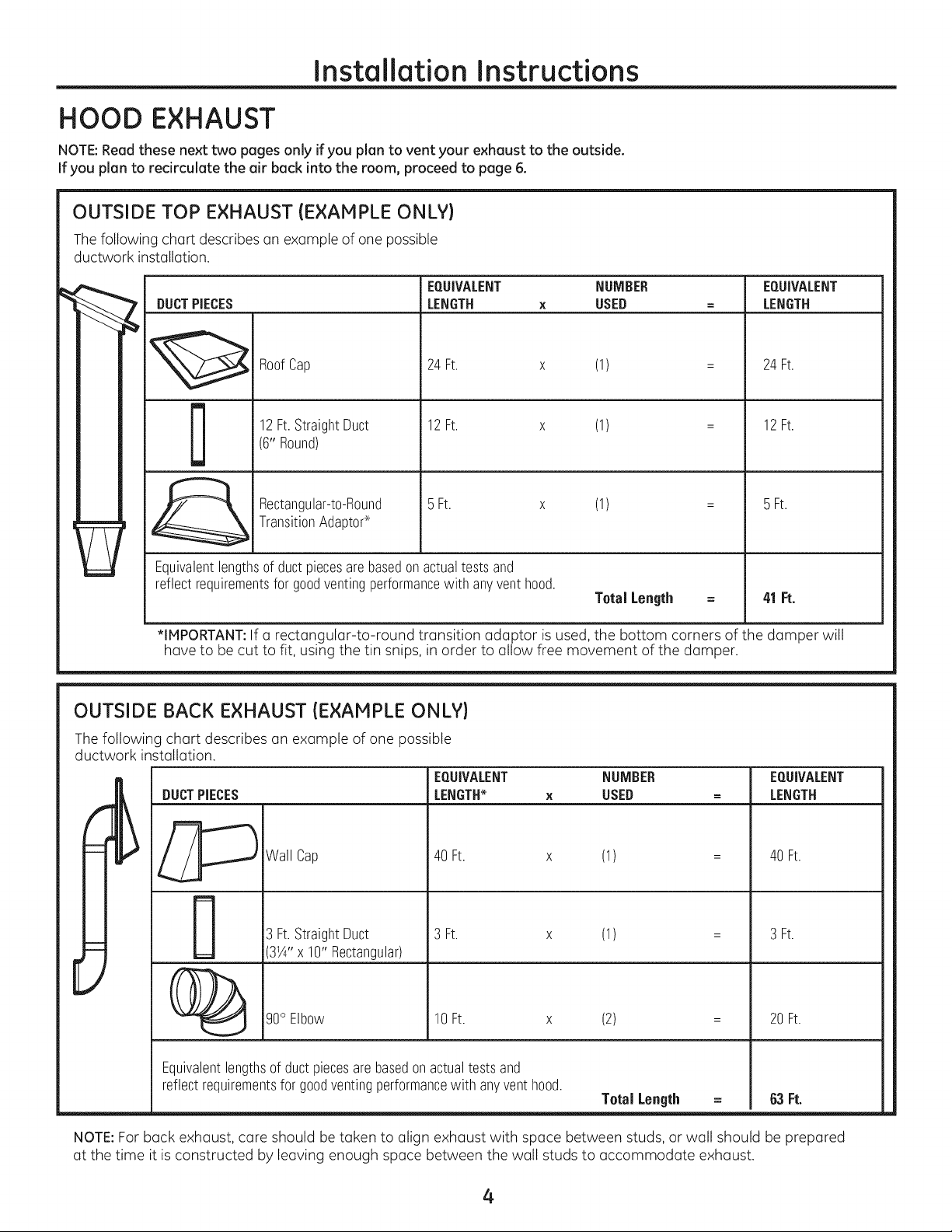
OUTSIDE TOP EXHAUST (EXAMPLE ONLY)
Thefollowing chart describes an example of one possible
ductwork installation.
EQUIVALENT NUMBER EQUIVALENT
DUCTPIECES
LENGTH x USED = LENGTH
RoofCap
12Ft.StraightDuct
D
Equivalentlengthsof ductpiecesarebasedonactualtestsand
reflectrequirementsfor goodventingperformancewith anyventhood.
*IMPORTANT:Ifa rectangular-to-round transition adaptor is used, the bottom corners of the dumper will
have to be cut to fit, using the tin snips, in order to allow free movement of the dumper.
(6"Round)
Rectangular-to-Round
TransitionAdaptod
24Ft. x (1)
12Ft. x (1)
BFt. x (1)
OUTSIDE BACK EXHAUST (EXAMPLE ONLY)
The following chart describes an example of one possible
ductwork installation.
EQUIVALENT NUMBER EQUIVALENT
DUCTPIECES
LENGTH_ x USED = LENGTH
Total Length =
24Ft.
12Ft.
BFt.
41 Ft.
Wall Cap
Ft.StraightDuct
314'' x 10" Rectangular)
40 Ft. x (1)
3 Ft. x (1)
40 Ft.
3 Ft.
E
g0° Elbow
Equivalentlengthsof ductpiecesarebasedonactualtestsand
reflectrequirementsforgoodventingperformancewith anyvent hood.
NOTE:For back exhaust, care should be taken to align exhaust with space between studs, or wall should be prepared
at the time it is constructed by leaving enough space between the wall studs to accommodate exhaust.
10 Ft. x (2)
Total Length = 63 Ft.
4
20 Ft.
Page 5
Installation Instructions
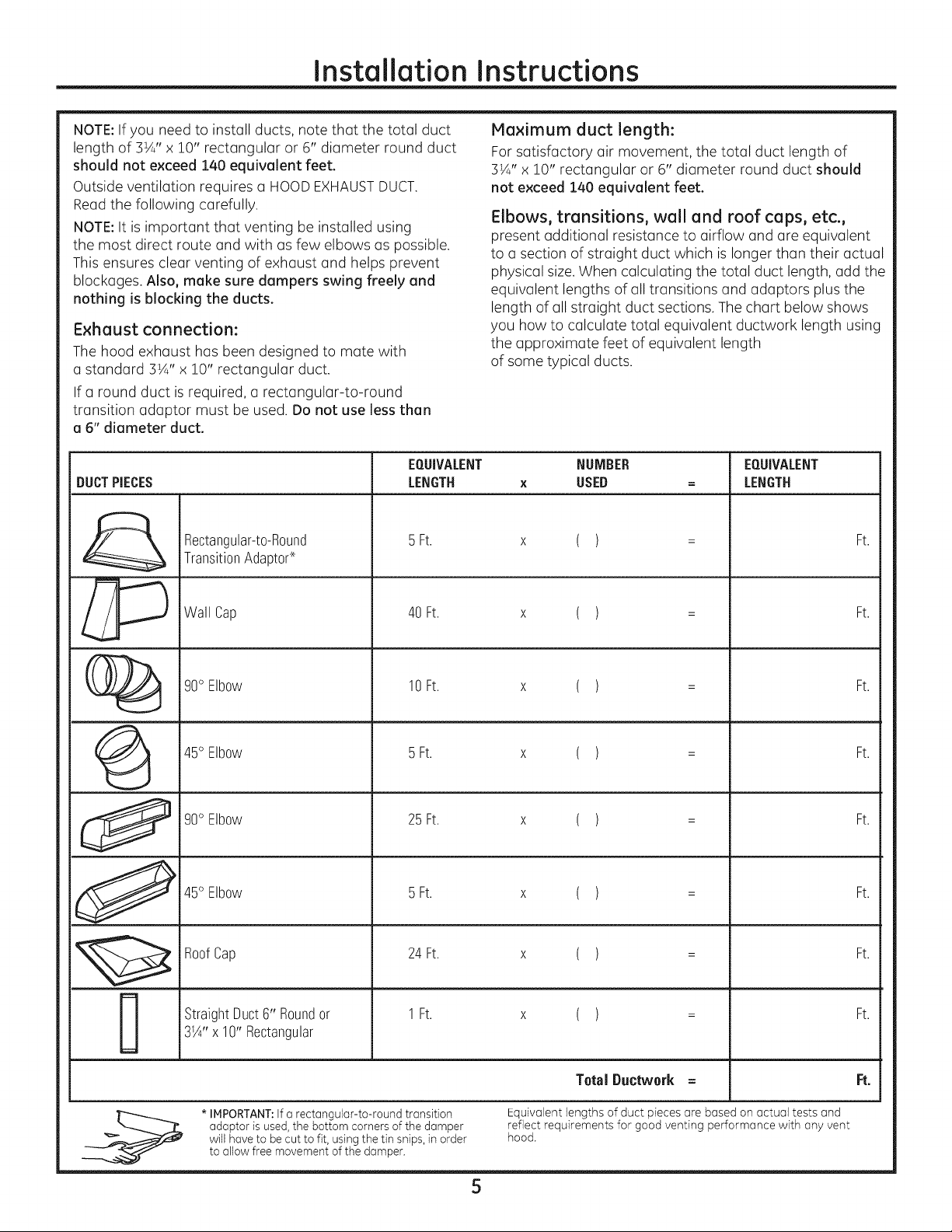
NOTE:If you need to install ducts, note that the total duct
length of 3¼" x 10" rectangular or 6" diameter round duct
should not exceed 140 equivalent feet.
Outside ventilation requires a HOODEXHAUSTDUCT.
Read the following carefully.
NOTE:It is important that venting be installed using
the most direct route and with as few elbows as possible.
This ensures clear venting of exhaust and helps prevent
blockages. Also, make sure dampers swing freely and
nothing is blocking the ducts.
Exhaust connection:
The hood exhaust has been designed to mate with
a standard 3½" x 10" rectangular duct.
If a round duct is required, a rectangular-to-round
transition adaptor must be used. Do not use less then
o 6" diameter duct.
EQUIVALENT NUMBER EQUIVALENT
DUCTPIECES LENGTH x USED = LENGTH
Rectangular-t0-R0und 5 Ft. x ( ) = Ft.
TransitionAdaptor-×.
Maximum duct length:
For satisfactory air movement, the total duct length of
3¼" x 10" rectangular or 6" diameter round duct should
not exceed 140 equivalent feet.
Elbows, transitions, wall and roof caps, etc.,
present additional resistance to airflow and are equivalent
to u section of straight duct which is longer than their actual
physical size. When calculating the total duct length, add the
equivalent lengths of all transitions and adaptors plus the
length of all straight duct sections. The chart below shows
you how to calculate total equivalent ductwork length using
the approximate feet of equivalent length
of some typical ducts.
_ Wall Cap 40 Ft. x ( ) = Ft.
(_ g0° Elbow 10Ft. x ( ) = Ft.
(_ 45° Elbow 5 Ft. x ( ) = Ft.
g0° Elbow 25 Ft. x ( ) = Ft.
45°EIb0w 5Ft. x ( ) = Ft.
RoofCap 24Ft. x ( ) = Ft.
StraightDuct6" Roundor 1 Ft. x ( ) = Ft.
3W'x 10"Rectangular
Total Ductwork = Ft.
* IMPORTANT:If a rectangular-to-round transition Equivalent lengths of duct pieces are based on actual tests and
adaptor is used, the bottom corners of the damper reflect requirements for good venting performance with any vent
will have to be cut to fit, using the tin snips, in order hood.
to allow free movement of the damper.
5
Page 6
Installation Instructions
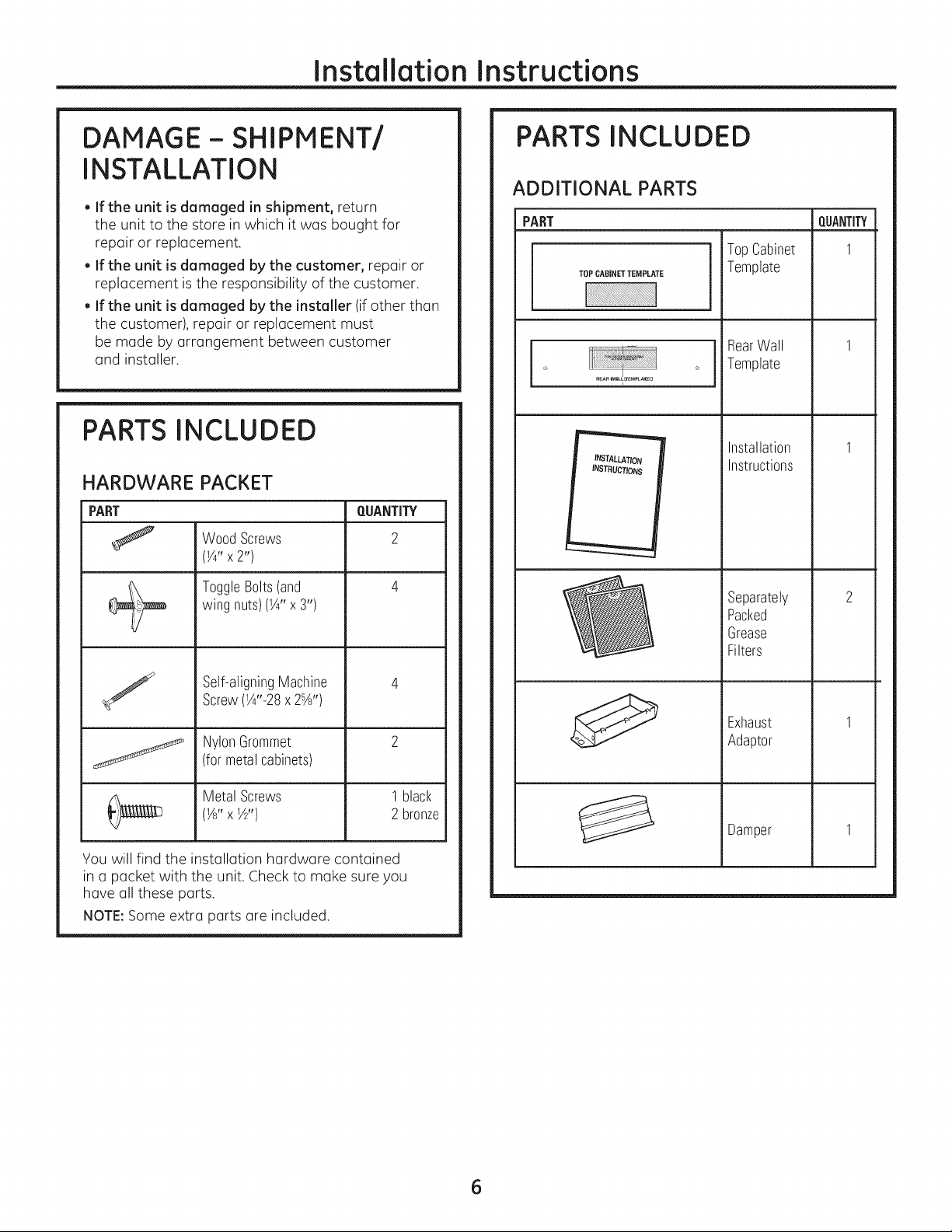
DAMAGE- SHIPMENT/
INSTALLATION
. If the unit is damaged in shipment, return
the unit to the store in which it was bought for
repair or replacement.
. If the unit is damaged by the customer, repair or
replacement is the responsibility of the customer.
. If the unit is damaged by the installer (if other than
the customer), repair or replacement must
be made by arrangement between customer
and installer.
PARTS INCLUDED
HARDWARE PACKET
PART
WoodScrews
(¼" x2")
ToggleBolts(and
wingnuts)(¼" x 3")
QUANTITY
2
PARTS INCLUDED
ADDITIONAL PARTS
PART
TOPCABINETTEMPLATE
INSTALLATION
INSTRUCTIONS
TopCabinet
Template
RearWall
Template
Installation
Instructions
Separately
Packed
Grease
Filters
m
QUANTITY
I
/
Youwill find the installation hardware contained
in a packet with the unit. Check to make sure you
have all these parts.
NOTE:Some extra parts are included.
Self-aligningMachine
Screw(¼"-28x2%')
NylonGrommet
(formetalcabinets)
Metal Screws
(W' xW')
1black
2 bronze
Exhaust
Adaptor
Damper
I
I
6
Page 7
Installation Instructions
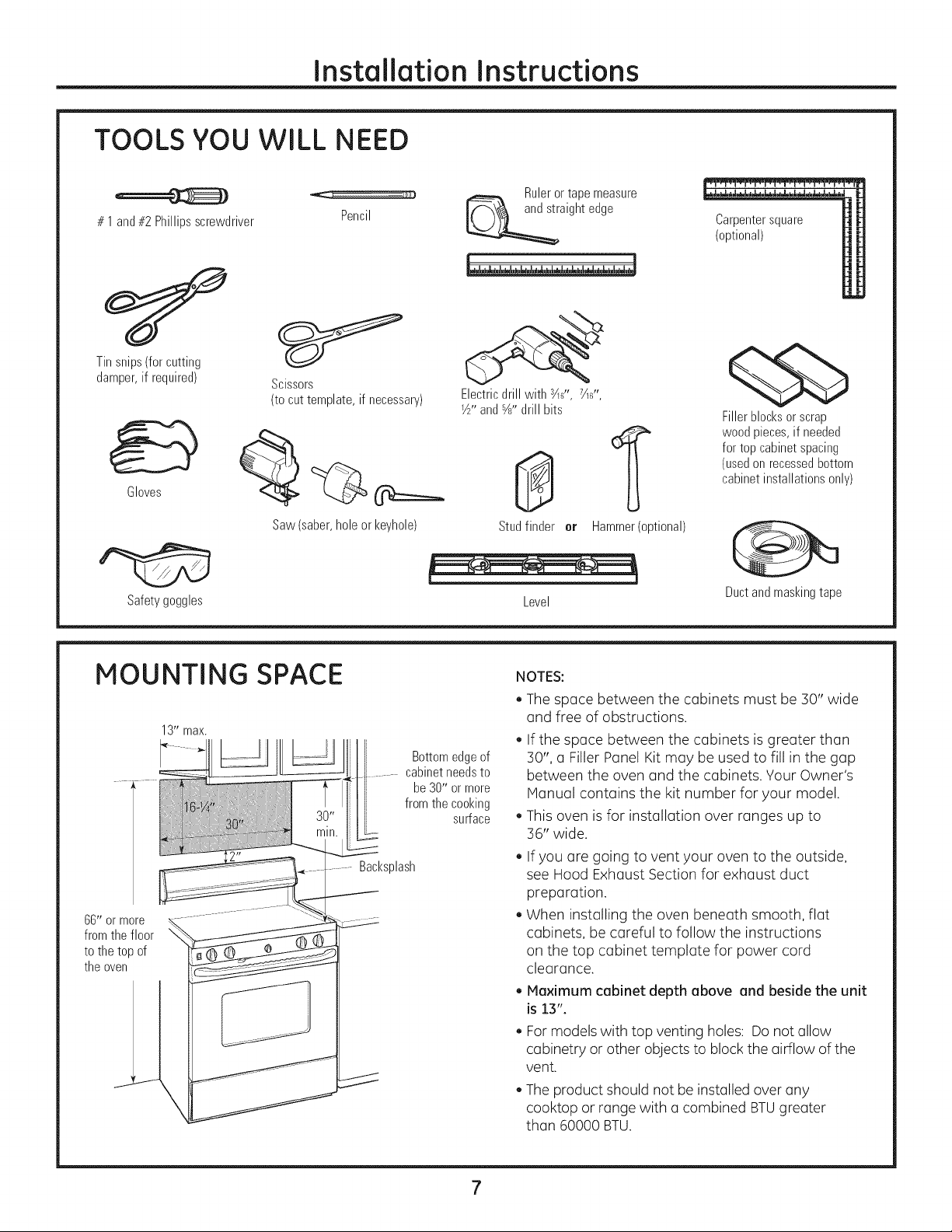
TOOLS YOU WILL NEED
# 1and#2Phillipsscrewdriver
Tinsnips(forcutting
damper,if required)
Gloves
Scissors
(to cut template, if necessary)
Pencil
Rulerortapemeasure
aightedge
Electricdrill with s½_,,7½6,,'
_½"and_" drill bits
Carpentersquare
(optional)
qSb
Fillerblocksorscrap
woodpieces,if needed
fortopcabinetspacing
(usedonrecessedbottom
cabinetinstallationsonly)
Saw(saber,holeorkeyhole)
Safety goggles
MOUNTING SPACE
13"max.
66"ormore
fromthefloor
tothetopof
theoven
Bottomedgeof
cabinetneedsto
be30" or more
fromthe cooking
Bacl<splash
Studfinder er Hammer(optional)
Level
NOTES:
* The space between the cabinets must be 30" wide
and free of obstructions.
, If the space between the cabinets is greater than
30", a Filler Panel Kit may be used to fill in the gap
between the oven and the cabinets. Your Owner's
Manual contains the kit number for your model.
surface
This oven is for installation over ranges up to
36" wide.
If you are going to vent your oven to the outside,
see Hood Exhaust Section for exhaust duct
preparation.
When installing the oven beneath smooth, flat
cabinets, be careful to follow the instructions
on the top cabinet template for power cord
clearance.
. Maximum cabinet depth above and beside the unit
is13".
, Formodels with top venting holes: Do not allow
cabinetry or other objects to block the airflow of the
vent.
, The product should not be installed over any
cooktop or range with a combined BTUgreater
than 60000 BTU.
Ductandmaskingtape
Page 8

Instollotion Instructions
-IPLACEMENT OF THE MOUNTING PLATE
REMOVING THE OVEN FROM
THE CARTON/REMOVING
THE MOUNTING PLATE
%
Remove the box containing the installation
instructions, filters, exhaust adaptor, damper
and the small hardware bag. Do not remove
the Styrofoam protecting the front of the oven.
[]
Fold back all 4 carton flaps fully against carton sides.
Then carefully roll the oven and carton over onto
the top side. The oven should be resting in the
Styrofoam.
%
Pullthe carton up and off the oven.
%
The mounting plate is attached to the back of the
oven. Remove the two screws holding it to the oven.
The plate will be used as the rear wall template and
for mounting the oven to the wall.
%
Setthe oven upright. Remove and properly discard
plastic bags and Styrofoam.
[_ FINDING THE WALL STUDS
Studs
Center_
[_ Findthe studs, using one of the following methods:
A. Stud finder - a magnetic device which locates nails.
OR
B. Use a hammer to tap lightly across the mounting
surface to find a solid sound. This will indicate
a stud location.
[_ After locating the stud(s),find the center by probing
the wall with a small nail to find the edges of the stud.
Then place a mark halfway between the edges.
The center of any adjacent studs should be 16" or 24"
from this mark.
[_ Draw a line down the center of the studs.
IMPORTANT: The microwave oven must be connected to
at least one wall stud.
%
Open the oven door and remove the styrofoam
pack from inside the oven. Remove the tape
covering the turntable hub.
8
Page 9
Installation Instructions
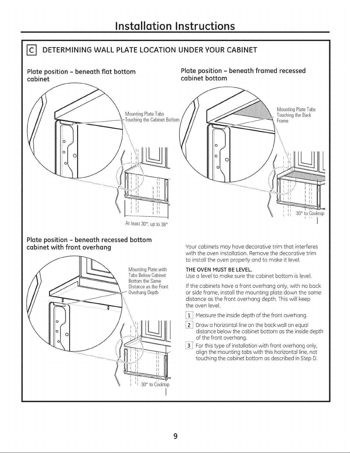
[_ DETERMINING WALL PLATE LOCATION UNDER YOUR CABINET
Plate position - beneath flat bottom
cabinet
O
MountingPlateTabs
the CabinetBottom
\
At least 30", up to 36"
Plate position - beneath framed recessed
cabinet bottom
MountingPlateTabs
Touchingthe Back
Frame
Plate position - beneath recessed bottom
cabinet with front overhang
MountingPlatewith
TabsBelowCabinet
BottomtheSame
Distanceasthe Front
OverhangDepth
0
0
C
30" to Cool<top
I
Your cabinets may have decorative trim that interferes
with the oven installation. Remove the decorative trim
to install the oven properly and to make it level.
THE OVEN MUST BE LEVEL.
Use a level to make sure the cabinet bottom is level.
If the cabinets have a front overhang only, with no back
or side frame, install the mounting plate down the same
distance as the front overhang depth. This will keep
the oven level.
[_ Measure the inside depth of the front overhang.
[_ Draw a horizontal line on the back wall an equal
1
distance below the cabinet bottom asthe insidedepth
of the front overhang.
[_ For this type of installation with front overhang only,
align the mounting tabs with this horizontal line,not
touching the cabinet bottom as described in Step D.
9
Page 10
Installation Instructions
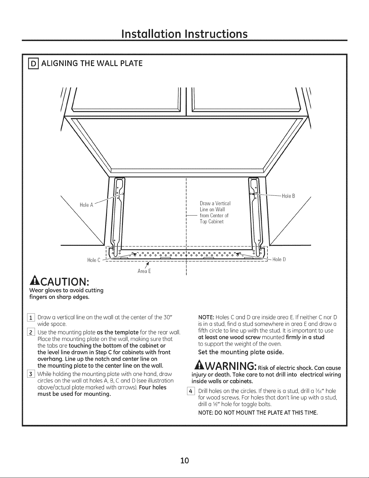
_ ALIGNING THE WALL PLATE
Hole
I
I
HoleC
4 T
AreaE J
ACAUTION'.
Wear glovestoavoidcutting
fingerson sharpedges.
[_ Draw a vertical line on the wall at the center of the 30"
wide space.
[] Usethe mounting plate as the template for the rear wall.
Placethe mounting plate on the wall, making sure that
the tabs are touching the bottom of the cabinet or
the level line drawn in Step Cfor cabinets with front
overhang. Line up the notch and center line on
the mounting plate to the center line on the wall.
[_ While holding the mounting plate with one hand, draw
circles on the wall at holesA, B,C and D (seeillustration
above/actual plate marked with arrows). Four holes
must be used for mounting.
Draw a Vertical
Line on Wall
r----- from Center of
Top Cabinet
olo
I
I
NOTE:Holes C and D are inside area E.If neither C nor D
isin a stud, find a stud somewhere in area Eand draw a
fifth circle to line up with the stud. It is important to use
at least one wood screw mounted firmly in a stud
to support the weight of the oven.
Set the mounting plate aside.
WARNING:Riskofelectricshock.Cancause
injury or death. Take care to not drill into electrical wiring
inside walls or cabinets.
[_ Drill holeson the circles. If there is astud, drill a 3A6"hole
for wood screws. Forholes that don't line up with a stud,
drill a %" hole for toggle bolts.
NOTE:DONOTMOUNTTHEPLATEATTHISTIME.
10
Page 11
Installation Instructions
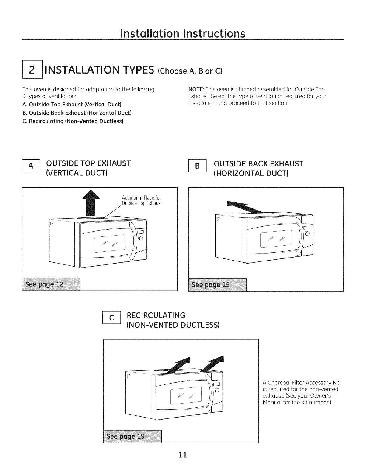
INSTALLATION TYPES
This oven is designed for adaptation to the following
3 types of ventilation:
A. Outside Top Exhaust (Vertical Duct}
B. Outside Back Exhaust (Horizontal Duct}
C. Recirculating (Non-Vented Ductless}
J_ OUTSIDE TOP EXHAUST
(VERTICAL DUCT)
AdaptorinPlacefor
OutsideTopExhaust
(Choose A, B or C)
NOTE:This oven is shipped assembled for Outside Top
Exhaust. Select the type of ventilation required for your
installation and proceed to that section.
r_ UTSIDE BACK EXHAUST
(HORIZONTAL DUCT)
1_ RECIRCULATING
(NON-VENTED DUCTLESS)
A Charcoal Filter Accessory Kit
is required for the non-vented
exhaust. (Seeyour Owner's
Manual for the kit number.)
11
Page 12
Installation Instructions
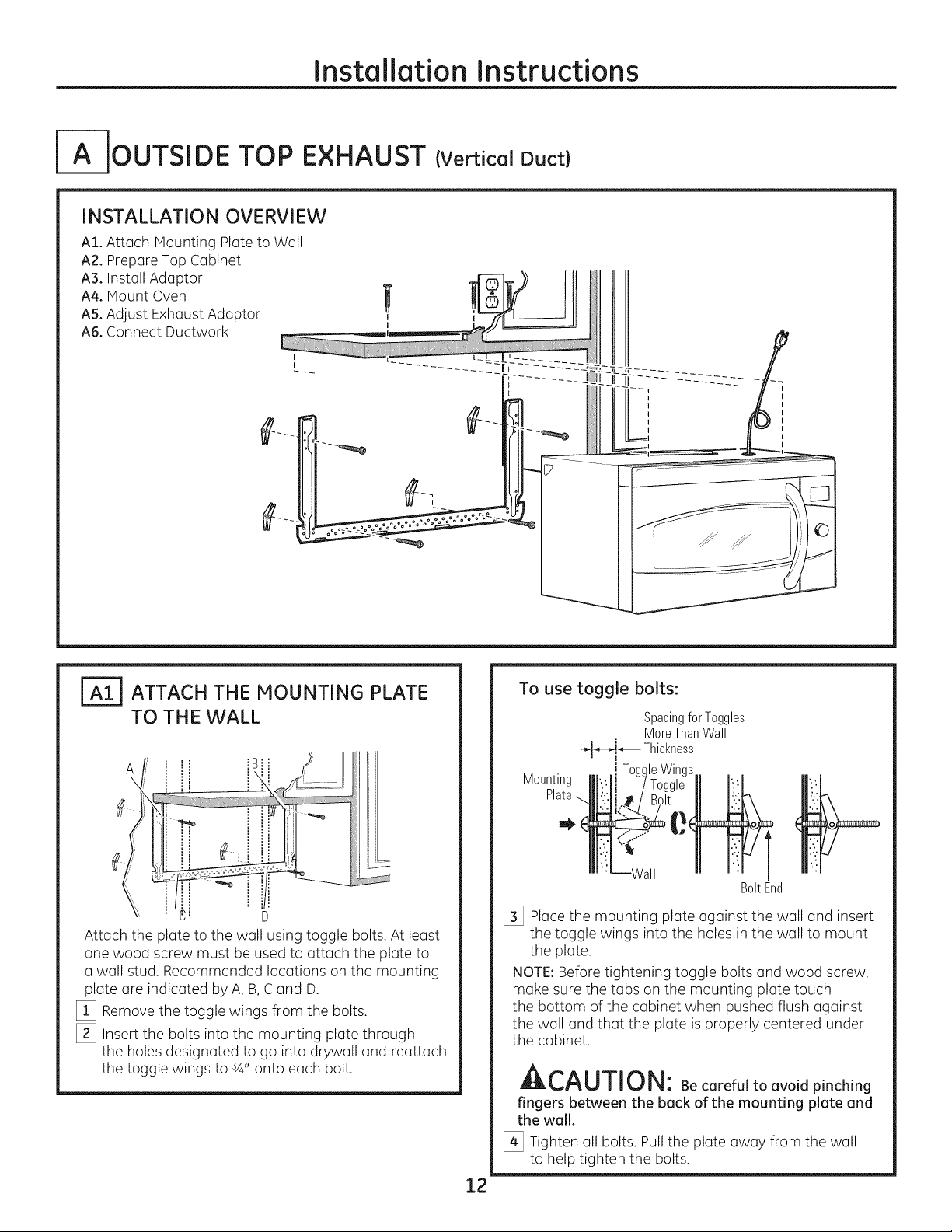
IA-IOUTSIDE TOP EXHAUST (Vertical Duct)
INSTALLATION OVERVIEW
AI. Attach Mounting Plate to Well
A2. Prepare Top Cabinet
A3. Install Adaptor
A4. Mount Oven
AS.Adjust Exhaust Adaptor
A6. Connect Ductwork
ATTACH THE MOUNTING PLATE
TO THE WALL
A
==,
.c D
Attach the plate to the well using toggle bolts. At least
one wood screw must be used to attach the plate to
a wall stud. Recommended locutions on the mounting
plate are indicated by A, B,C and D.
[_ Remove the toggle wings from the bolts.
[_ Insert the bolts into the mounting plate through
the holes designated to go into drywall end reettech
the toggle wings to ¾" onto each bolt.
To use toggle bolts:
SpacingforToggles
MoreThanWall
-,-I_-_!_- Thickness
Mounting
[_ Place the mounting plate against the wall and insert
the toggle wings into the holes in the wall to mount
the plate.
NOTE:Before tightening toggle bolts and wood screw,
make sure the tabs on the mounting plate touch
the bottom of the cabinet when pushed flush against
the wall and that the plate is properly centered under
the cabinet.
i ToggleWings
BoltEnd
Ar,^l i-rir,_l
LIILI_,I"_UIIIIJ|_I: Be careful to avoid pinching
fingers between the beck of the mounting plate end
the wall.
[_ Tighten all bolts. Pull the plate away from the wall
to help tighten the bolts.
12
Page 13
Installation Instructions
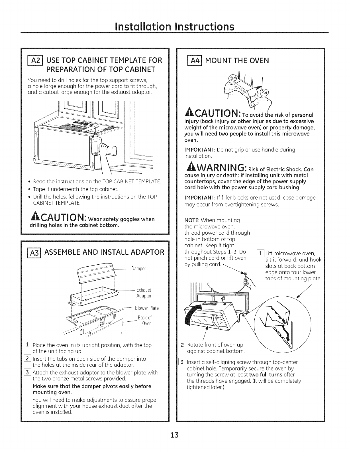
_USE TOP CABINET TEMPLATE FOR
PREPARATION OF TOP CABINET
You need to drill holes for the top support screws,
a hole large enough for the power cord to fit through,
and a cutout large enough for the exhaust adaptor.
. Readthe instructions on the TOPCABINETTEMPLATE.
. Tape it underneath the top cabinet.
. Drillthe holes, following the instructions on the TOP
CABINETTEMPLATE.
A,--^l i-T-,,-_i,!
Wearsafetygoggleswhen
drilling holes in the cabinet bottom.
ASSEMBLE AND INSTALL ADAPTOR
Damper
_ MOUNT THE OVEN
CAUTI riskofpersonal
injury (back injury or other injuries due to excessive
weight of the microwave oven) or property damage,
you will need two people to install this microwave
oven.
IMPORTANT:Do not grip or use handle during
installation.
m;&W_l_|_i I |_11_: Risk of Electric Shock. Can
cause injury or death: If installing unit with metal
countertops, cover the edge of the power supply
cord hole with the power supply cord bushing.
IMPORTANT:If filler blocks are not used, case damage
may occur from overtightening screws.
NOTE:When mounting
the microwave oven,
thread power cord through
hole in bottom of top
cabinet. Keep it tight
throughout Steps 1-3. Do
not pinch cord or lift oven
by pulling
[_3 Lift microwave oven,
tilt it forward, and hook
slots at back bottom
edge onto four lower
tabs of mounting plate.
,1-11 ...... Exhaust
i
i BlowerPlate
.... Oven
[_3 Placethe oven in its upright position, with the top
of the unit facing up.
[_3 Insert the tabs on each side of the dumper into
the holes at the inside rear of the adaptor.
[_3 Attach the exhaust adaptor to the blower plate with
the two bronze metal screws provided.
Make sure that the damper pivots easily before
mounting oven.
You will need to make adjustments to assure proper
alignment with your house exhaust duct after the
oven is installed.
Adaptor
Bacl<of
[_3 Rotate front of oven up
against cabinet bottom.
[_3 Insert a self-aligning screw through top-center
cabinet hole. Temporarily secure the oven by
turning the screw at least two full turns after
the threads have engaged. (It will be completely
tightened later.)
13
Page 14
Installation Instructions
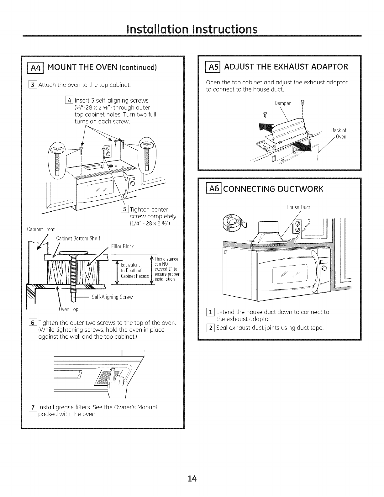
_ MOUNT THE OVEN Icontinued}
[_ Attach the oven to the top cabinet.
[_ Insert 3 self-aligning screws
(¼"-28 x 2 %') through outer
top cabinet holes. Turn two full
turns on each screw.
Tighten center
screw completely.
(1/4"- 28x 2_")
CabinetFront
CabinetBottomShelf
FillerBlock
_=5] ADJUST THE EXHAUST ADAPTOR
Open the top cabinet and adjust the exhaust adaptor
to connect to the house duct.
Damper
_q _ Backof
i_]_J_/ _-r_ _ Oven
_6] CONNECTING DUCTWORK
HouseDuct
__ _This distance
Equivalent |can NOT
I to Depthof | exceed2" to
Cabinet Recess | ensu!,e I_roper
-- Self-AligningScrew
OvenTop
[] Tighten the outer two screws to the top of the oven.
(While tightening screws, hold the oven in place
against the wall and the top cabinet.)
..............................................................................................111 i _],
[_ Install grease filters. Seethe Owner's Manual
packed with the oven.
,/
lnstallatlon
[_3 Extend the house duct down to connect to
the exhaust adaptor.
[_3 Seal exhaust duct joints using duct tape.
14
Page 15
Installation Instructions
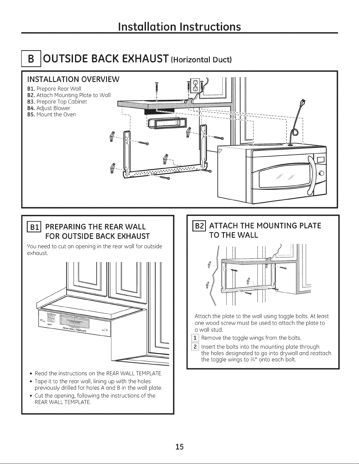
-- OUTSIDE BACK EXHAUST (Horizontal Duct)
INSTALLATION OVERVIEW
B1. Prepare Rear Wall
B2.Attach Mounting Plate to Wall
B3. Prepare Top Cabinet
B4.Adjust Blower
B5. Mount the Oven
_ PREPARING THE REAR WALL
FOR OUTSIDE BACK EXHAUST
You need to cut an opening in the rear wall for outside
exhaust.
, Readthe instructions on the REARWALLTEMPLATE.
, Tape it to the rear wall, lining up with the holes
previously drilled for holes A and B in the wall plate.
, Cut the opening, following the instructions of the
REARWALL TEMPLATE.
ATTACH THE MOUNTING PLATE
TO THE WALL
Attach the plate to the wall using toggle bolts. At least
one wood screw must be used to attach the plate to
a wall stud.
[_ Remove the toggle wings from the bolts.
[_ Insert the bolts into the mounting plate through
the holes designated to go into drywall and reattach
the toggle wings to sA"onto each bolt.
15
Page 16

Installation Instructions
To use toggle bolts:
SpacingforTogglesMore
-_1_--_,_-- ThanWallThickness
Mounting ToggleWings
Plate_. !
Wall
BoltEnd
[_ Placethe mounting plate against the wall and insert
the toggle wings into the holes in the wall to mount
the plate.
NOTE:Before tightening toggle bolts and wood screw,
make sure the tabs on the mounting plate touch
the bottom of the cabinet when pushed flush against
the wall and that the plate is properly centered under
the cabinet.
CAUTI ON: Be careful to avoid pinching
fingers between the back of the mounting
plate and the wall.
[_ Tighten all bolts, Pull the plate away from the wall
to help tighten the bolts.
[=_ ADAPTING BLOWER FOR
OUTSIDE BACK EXHAUST
[_3 Remove the three screws that hold the blower
plate to the oven. Slide blower plate from under
its retaining flange. Remove and save the screw
that holds blower motor to oven.
Retaining _ _i!b_<_
Flange
\ ,owerP,ate
__ BlowerMotor
Screw
[_3 Carefully pull out the blower unit. Thewires
will extend far enough to allow you to adjust
the blower unit.
End
r_USE TOP CABINET TEMPLATE
FOR PREPARATION OF TOP
CABINET
You need to drill holes for the top support screws and
u hole large enough for the power cord to fit through.
. Read the instructions on the TOP CABINET
TEMPLATE.
. Tape it underneath the top cabinet.
. Drill the holes, following the instructions on the
TOP CABINET TEMPLATE.
JuLL, t'_U/IIU |_1: Wear safety goggles when
drilling holes in the cabinet bottom.
[_3 Rotate blower unit counterclockwise 180°.
BeforeRotation AfterRotation
Backof
Oven Oven
[_ Gently remove the wires from the grooves.
Reroute the wires through grooves on other side
of the blower unit.
BeforeRerouting After Rerouting
WiresRoutedThroughRightSide Wires RoutedThroughLeftSide
3acl<of
16
Page 17

Installation Instructions
[_ Roll the blower unit 90° so that fan blade openings
are facing out the buck of the oven.
BeforeRollim
Backof
Oven
Locate the two "knockout" plates, on the rear oven
%
panel, near the top of the oven.
Using tin snips, carefully cut the web area from the
two holes side-by-side (that secure the knockouts to
the oven). Cut all four webs on both rear knockouts;
this will allow the ventilation fun airflow to exhaust
out the rear of the oven.
After Rolling
Backof
Oven
Ar-^l I-T-i_m
n_u/iul_: Besuretotrimthesharp
edges from the openings after removing the
knockout plates.
Oven Rear Panel
Replace the blower plate in the same position
%
as before with the screws.
_-_ BlowerPlateScrews
_J _:j___ Backof Oven
.... J ..... j.s>--
[_ Insert the tabs on each side of the damper
into the holes at the inside rear of the adaptor.
I
[_ Attach the exhaust adaptor to the rear of the oven
by sliding it into the guides at the top center of the
back of the oven.
BlowerPlate
--- Exhaust
Adaptor
Snipall4webs
oneachknockout
panelandremove
____ themetalknockouts
[_ Place the blower unit back into the opening.
jEnd A
EndB ) J ,_.._ ...........
WA RNING:Riskofelectricshock
can cause injury or death. Do not pull or stretch
the blower unit wiring, make sure the wires are
not pinched..
NOTE:The blower unit exhaust openings should
match exhaust openings on rear of microwave oven.
ExhaustAda
Slideexhaust
adaptorinto
guideson
ovenrear.
Locking
Tabs Guides
Push in securely until it is inthe lower locking tabs.
Take care to assure the damper hinge is installed
so that it is at the top and that the damper swings
freely.
[_ Secure the exhaust adaptor to the oven with
the two bronze metal screws provided.
Damper
(hingesideup)
BackofOven
Screws
17
Page 18

[_ MOUNT THE OVEN
Installation Instructions
CabinetFront
CabinetBottomShelf
FillerBlock
*_Thisdistance
--_quivalent |can NOT
I to Depthof | exceed2" to
I CabinetRecess| ensur,eI_roper
lnstallatlon
ACAUTI " riskof personal
injury (back injury or other injuries due to excessive
weight of the microwave oven) or property damage,
you will need two people to install this microwave
oven.
IMPORTANT:Do not grip or use handle during
installation.
WARN ING: RiskofElectricShock.Can
cause injury or death: If installing unit with metal
countertops, cover the edge of the power supply
cord hole with the power supply cord bushing.
IMPORTANT:If filler blocks are not used, case damage
may occur from overtightening screws.
NOTE:When mounting
the microwave oven,
thread power cord through
hole in bottom of top
cabinet. Keep it tight
throughout Steps 1-3. Do
not pinch cord or lift oven
by pulling
[_ Lift microwave oven,
tilt it forward, and hook
slots at back bottom
edge onto four lower
tabs of mounting plate.
-- Self-AligningScrew
OvenTop
[_ Attach the oven to the top cabinet.
[_ Insert 3 self-aligning screws
(¼"-28 x 2 %') through outer
top cabinet holes. Turn two full
turns on each screw.
Tighten center
screw completely
(1/4" x 28 x 2%")
[_ Rotate front of oven up
against cabinet bottom.
[_ Insert a self-aligning screw through top-center
cabinet hole. Temporarily secure the oven by
turning the screw at least two full turns after
the threads have engaged. (It will be completely
tightened later.)
[] Tighten the outer two screws to the top of the
oven. (While tightening screws, hold the oven
in place against the wall and the top cabinet.)
II I
/
[_ Install grease filters. Seethe Owner's Hanual
packed with the oven.
18
Page 19

Installation Instructions
-- RECIRCULATING (Non-Vented Ductless}
INSTALLATION OVERVIEW
C1. Attach Mounting Plate to Wall
C2. Prepare Top Cabinet
C3. Adjust Blower
C4. Mount the Oven
CE Install Charcoal Filter (not suppliedt
ATTACH THE MOUNTING PLATE
TO TH E WALL
Attach the plate to the wall using toggle bolts. At least
one wood screw must be used to attach the plate to
a wall stud.
[] Remove the toggle wings from the bolts.
[_ Insert the bolts into the mounting plate through
the holes designated to go into drywall and reattach
the toggle wings to ¾" onto each bolt.
To use toggle bolts:
SpacingforToggles
MoreThanWall
÷.,_-_L,-- Thickness
i
Mounting
iToggleWings
_/all
BoltEnd
[_ Place the mounting plate against the wall and insert
the toggle wings into the holes in the wall to mount
the plate.
NOTE:Before tightening toggle bolts and wood screw,
make sure the tabs on the mounting plate touch the
bottom of the cabinet when pushed flush against the
wall and that the plate is properly centered under the
cabinet.
ACAUTION: Be careful to avoid pinching
fingersbetween the back ofthe mounting plateand
the well.
[_ Tighten all bolts. Pull the plate away from the wall
to help tighten the bolts.
USETOPCABINETTEMPLATE
FORPREPARATIONOF TOPCABINET
You need to drill holes for the top support screws and
a hole large enough for the power cord to fit through.
. Read the instructions on the TOP CABINET
TEMPLATE.
. Tape it underneath the top cabinet.
. Drill the holes, following the instructions on the TOP
CABINET TEMPLATE.
At-^, ,-,-,r,,,,
LILII_t'_IJ|IIIJ|_I:Wear safety goggles when
drilling holes in the cabinet bottom.
19
Page 20

Installation Instructions
ADAPTING BLOWER
FOR RECIRCULATION
NOTE:The exhaust adaptor with damper is not
needed for recirculating models. You may want
to save them for possible future use.
[_3 Remove and save screws that hold blower plate
to the oven.
i_ _ BlowerPlateScrews
_-_-- BackofOven
[_3 Slide the blower plate from under its retaining
flange and lift it off. Remove and save screw that
holds the blower motor to oven.
Retaining __
Flange _ _ "___..... _,_
[_3 Carefully pull out the blower unit. Thewires
will extend far enough to allow you to adjust
the blower unit.
[_ Rollthe blower unit 90° so that fun blade openings
are facing toward the front of the oven.
Roll
_ -___,_7 _ BlowerPlate
Screw
/ Jl IJl
i
NOTE:Make sure wires remain routed in the grooves
of the motor frame.
2O
Page 21

Installation Instructions
_ ADAPTING BLOWER FOR
RECIRCULATION Icontinued)
[_ Place the blower unit back into the opening.
_WARN ING: Riskofelectricshock
can cause injury or death. Do not pull or stretch
the blower unit wiring. Make sure the wired are
not pinched.
[_ Secure blower unit to oven with the 2
removed in Step 2. Insert the screw in bottom right
screw hole on the back of the oven.
[_ Reploce blower plate with the screws removed in
Step 1.
,_ _ BlowerPlateScrews
screws
[_ MOUNT THE OVEN
A.--^.,-r,_ _,
klLk.,/_U/IU |_1: TOavoid the risk of personal
injury (back injury or other injuries due to excessive
weight of the microwave oven) or property damage,
you will need two people to install this microwave
oven.
IMPORTANT:Do not grip or use handle during
installation.
WA RNING:RiskofElectricShock.Can
cause injury or death: If installing unit with metal
countertops, cover the edge of the power supply
cord hole with the power supply cord bushing.
IMPORTANT:If filler blocks (]re not used, case damage
may occur from overtightening screws.
BackofOven
Screw
NOTE:When mounting
the microwave oven,
thread power cord through
hole in bottom of top
cabinet. Keep it tight
throughout Steps 1-3. Do
not pinch cord or lift oven
by pulling
[_ Rotate front of oven up
against cabinet bottom.
[_ Lift microwave oven,
tilt it forward, and hook
slots at back bottom
edge onto four lower
tabs of mounting plate.
21
Page 22

Installation Instructions
MOUNT THE OVEN (continuedl
[_ Insert a self-aligning screw through top-center
cabinet hole. Temporarily secure the oven by
turning the screw at least two full turns after
the threads have engaged. (It will be completely
tightened later.)
CabinetFront
CabinetBottomShelf
FillerBlock
--_quivalent | canNOT
I to Depthof / exceed2"to
Cabinet Recess| ensur,e I_roper
_ _.lnstallatlon
-- Self-AligningScrew
Oven Top
[_ Insert 3 self-aligning screws
(¼"-28 x 2%") through outer
top cabinet holes.Turn two full
turns on each screw.
INSTALLING THE CHARCOAL
FILTER
[_ Remove 2 screws on top of oven,just above
the grille panel, using a Phillips screwdriver.
[_ Open the door.
[_ Remove the grille. Slide the grille to the left then pull
out.
Thisdistance
[] Insert the filter into the oven as shown until it fits
squarely into place. Itwill rest at an angle behind
the front lower tabs. When properly installed,
the wire mesh of the filter should be visible
from the front.
hten center
screw completely
(!/4" x 28 x 2%")
[] Tighten the outer two screws to the top of the
oven. (Whiletightening screws, hold the oven
in place against the wall and the top cabinet.)
tabs
Charcoalfilter
....._2&____
[_ Replace the grille and the 2 top screws.
[_ Close the door and replace left side screw.
[_ Install grease filters. Seethe Owner's Manual
packed with the oven.
22
Page 23

Installation Instructions
BEFORE YOU USE YOUR OVEN
r_ vlake sure the oven has been installed
according to instructions.
Remove all packing material from the oven.
(continued)
B]
240 V Models: Thewall outlet receptacle
recommended for this appliance is NEiVlA
#14-30R and accepts the four-prong grounded
plug of this appliance.
NEMA14-30R
Wall Receptacle
Ensureproper
groundexists
beforeuse.
. m
[_] Replace house fuse or turn breaker back on.
r_ 120 v Models: Plug power cord into
a dedicated 15- to 20-amp electrical outlet.
[_] Read the Owner's Manual.
r_ EEP INSTALLATION INSTRUCTIONS
FOR THE LOCAL INSPECTOR'S USE.
Ensureproper
groundexists
beforeuse.
Where a standard two-prong wall receptacle
is encountered, it is very important to have it
replaced with a properly grounded three-prong
wall receptacle, installed by a qualified
electrician.
23
Page 24

49-40650-1
MFL59060904
(07-12 GE)
Printed in Korea
24
Page 25

I strucci
de i stal
i
ANTES DE EMPEZAR
Horno para colocar
enclma de la estufa
PSA1200,PSA1201,PSA2200,PSA2201,
ZSA1201,ZSA1202,ZSA2201 & CSA1201
Lea estus instrucciones completa y cuidadosumente.
. IMPORTANTE - GuGrdeestcls
instrucciones para el uso clel inspector local.
. IMPORTANTE - Cumplacontodoslos
c6digos y ordenc]nzc]sgubernc]mentc]les.
. Nota para el instalador - Aseg0resede dejc]r
estc]sinstrucciones con el consumidor.
. Nora para el consumidor - Guc]rde estc]s
instrucciones pGrGfuture referenciu.
Nivel de destrezas - L(] instalaci6n de este apc]rato
requiere de destrezas b6sicas de mec6nicGy electricidGd.
La instalaci6n (]propic]d(] es responsabilidad
del instalGdor.
La fGIIGdel producto debido GunGinstGIGci6n
inapropiada no est6 cubierta por la garant[a.
25
LEA CUIDADOSAMENTE.
GUARDE ESTAS INSTRUCCIONES.
Page 26

Instruccionesde instalaci6n
CONTENIDO
Informaci6n general
Instrucciones de seguridad importantes ................... 27
Requisitos el_ctricos ...................................................... 27
Campana de escape ............................................... 28, 29
Da6os - Envio / Instalaci6n .......................................... 30
Partes incluidas ..............................................................30
Herramientas que necesitar6 ...................................... 31
Espacio de montaje ........................................................31
Guia de instalaci6n paso por paso
C6mo colocar el plato de montaje .......................32-34
C6mo remover el plato de montaje .....................32
C6mo encontrar madera s61ida
en la pared .......................................................................32
C6mo determinar la Iocalizaci6n
de las placas de la pared ..........................................33
[_ Recirculaci6n ..........................................................43-46
C6mo adherir la placa de
montaje a la pared............................................43
Preparaci6n del gabinete superior .............43
C6mo adaptar el calefactor
para la recirculaci6n .................................44, 45
C6mo montar el homo ............................45, 46
C6mo instalar el filtro de carbonilla ..........46
Antes de comenzar a usar su horno .........................47
C6mo alinear la placa de la pared .......................34
Tipos de instalaci6n ................................................35-46
[_ Escape superior ....................................
C6mo adherir la placa de
montaje a la pared ............................................36
Preparaci6n del gabinete superior ............37
Ensamblaje e instalaci6n
del adaptador ......................................................37
C6mo montar el homo .............................37, 38
C6mo ajustar el adaptador de escape....38
C6mo conectar el conducto .........................38
[]_ Escape posterior externo ..................................
C6mo preparar la pared posterior
para el escape posterior exterior ...............39
C6mo adherir el plato de
monta]e a la pared .....................................39, 40
Preparaci6n del gabinete superior ............40
exterior 36-38
39-42
C6mo adaptar el calefactor para
el escape posterior exterior ....................40, 41
C6mo montar el homo ....................................42
26
Page 27

Instruccionesde instalaci6n
NSTRUCCIONES DE SEGURIDAD INPORTANTES
Este producto requiere un tomacorriente el_ctrico
de tres pates conectado a tierra. El instalador debe
Ilevar a cuba una inspecci6n de continuidad a tierra
en la caja el6ctrica antes de comenzar la instalaci6n
para asegurar qua la caja tomacorriente est6 conectada
a tierra de manera apropiada. Si no Io est6, o si
el tomacorriente no cumple con los requisitos
el6ctricos indicados (bujo la secci6n REq)UISITOS
ELECTRICOS),se debar6 recurrir a un t_cnico
calificado pare corregir cualquier deficiencia.
PRECAUCION:
Para seguridad personal,
remueva el fusible de la casa
o abra el interruptor de circuito antes
de comenzar la instalaci6n
para evitar descargas el6ctricas
severas o fatales
AAI_r= n,=rr _ f_| A
R esgodeOescarga
El_ctrica. Puede ocasioner lesiones ole muerte:
ESTEELECTRODOMI_STICOSEDEBECONECTARATIERRA
DE FORMACORRECTAafin de evitar descargas severas o
mortales.
Nlodelos de 120 V
El cable de corriente de este
electrodom_stico contiene
un enchufe de 3 pates
(cone×i6n a tierra} qua se
conecta a un tomacorriente
de pared est6nder de 3
cables (conexi6n a tierre)
pare minimizer la posibilidad
de riesgos de descargas
usa[
Modelos de 240 V
Tomacorriente
deparedNEMA14-30R
AsegLirese de que
existe una conexi6n a
tierraapropiada antes del
Cuendo se encuentre un tomecorriente de pared de dos
enchufes, se deber6 reemplazar par uno conectado a
tierra de farina adecuada de tres cables, y debar6 ser
instalado par un electricista calificado.
el_ctricas par parte del
mismo.
The wall outlet receptacle
recommended for this
application is NEMA#:14-
]OR and accepts the four-
prong grounded plug of
this appliance.
A^r,_ irnT_ir,^
R esgodeOescarge
El_ctrica. Puede ocasionar lesionesola muerte: NUNCA,
bajo ninguna circunstancia, corte, deforme o elimine
ninguna de las puntes de los cables de corriente. No use
un prolongador. Si no secumple con esto, se podr6n
producir incendios..
_Amnrr^ rlAkl
LLr_r__.,_u _,|_j|_: Porrazones de
seguridad, la superficie de montaje deber6 poder
soporter la carga del gabinete, sumado al peso
agregado de este producto de entre 63 !#85 fibres,
adem6s de cargas adicionales en el homo de haste 50
libras o un peso total de entre :1:13y :135libras.
J
APRECAUCION: Parrazonesde
seguridad, este producto no se puede instalar en
arreglos de gabinete tales coma una isle o peninsula.
Sedebe montar TANTO a un gabinete superior coma a
une pared.
APRECAUCION: A deevitarelriesgo
de lesi6n personal (lesi6n en la espalda u otras
lesiones debido a peso excesivo del homo de
microondas} o da_os sabre el producto, deber6 canter
con la ayude de dos personas pare instalar este horno
de microondas..
s
_m
REgUISITOS ELECTRICOS
Modelos de 120 V
La clasificaci6n del producto es de 120 vatios CA(AC),
60 hertz, 15 amperios, y 1.70 kilovatios. Este producto
debe estar conectado a un circuito de suministro del
voltaje y frecuencia apropiados. Eltamafio del alambre
debe conformarse a los requisitos del National Electric
Code o al c6digo local en efecto para este [ndice
de kilovatios. Elcable el_ctrico de alimentaci6n y el
interruptor deber6n Ilevarse a un tomacorriente 6nico
conectado a tierra de 15 a 20 amperios. La caja del
tomacorriente debar6 estar Iocalizada en el gabinete
encima del horno. La caja del tomacorriente debe
ser instalada par un electricista calificado y debe
conformarse al National Electrical Code o al c6digo
local en efecto.
Modelos de 240 V
La clasificaci6n del producto es de 240/208 voltios CA,
60 hercios, 30 amperios y 6.5 kilovatios. Este producto
debe conectarse a un circuito derivado individual con
adecuada conexi6n a tierra, protegido par interruptores
de circuito y fusibles con retraso. Eltamaho del cable
debe cumplir con los requisitos del C6digo El_ctrico
Nacional o con el c6digo local vigente para esta
clasificaci6n de kilovatios. La caja de distribuci6n
debe ester ubicada en el gabinete sabre el horno.
Un electricista calificado debe instalar la caja de
distribuci6n y el circuito de suministro y _stos deben
cumplir con el C6digo EI6ctrico Nacional o con el c6digo
local vigente.
27
Page 28

Instruccionesde instalaci6n
CAMPANA DE ESCAPE
NOTA:Lea las siguientes dos p6ginas solamente si planea ventilar elescape hacia elexterior.
Si por el contrario planea recircular el aire de vuelta hacia el sai6n, contin6e en la p6gina 30.
ESCAPE SUPERIOR EXTERNO (EJEMPLO SOLAMENTE)
La siguiente tabla describe un ejemplo de una posible
instalaci6n de red de conductos.
LONGITUD NOMERO
PARTESDELCONDUCTO
Tapadeltecho
_m
Conductorectode 12pies
(redondode6")
m
derect6nguloa redondo-×
AdaptadordetransiciOn 5 pies x (1) = 5 pies
LaIongituddelas partesde losconductosequivalentesest,1basadaen pruebasrealesy reflejan
losrequisitosparaIograrunabuenaventilaciOnconcualquiercampanadeescape.
*IMPORTANTE:Sise us(] un (]d(]pt(]dor de tr(]nsici6n de rect6ngulo (] redondo, I(]sesquin(]s del rondo
del regul(]dor de tiros deber6n cort(]rse p(]r(] que enc(]jen, us(]ndo I(]s tUer(]sde corte, p(]r(] permitir
el movimiento libre del regul(]dor de tiros.
EQUIVALENTE x USADO
24pies x (1)
12pies x (1)
ESCAPE POSTERIOR EXTERNO (EJEMPLO SOLAMENTE)
LONGITUD
EQUIVALENTE
24pies
12pies
Longitudtotal = 41 pies
La siguiente tabl(] describe un ejemplo de un(] posible
instalaci6n de red de conductos.
LONGITUD NOMEBO
PARTES DEL CONDUCTO
Tapadepared
Conductorectode3 pies
(rectangularde31/4"x 10'I
_ Cododeg0° 10pies x (2)
LaIongituddelas
requisitosparaIograrunabuenaventilaciOnconcualquiercampanadeescape.
NOTA:Paraelescapeposterior,sedebetenetcuidadoal alinearelescapeentrelosespaciosdelospostesderigadela pared,o}apareddeberiaser
preparadaenelmomentodesuconstrucci6ndejandosuficienteespacioentrelospostesderigadela paredparaacomodarelescape.
partesde losconductosequivalentesest_Sbasadaenpruebasrealesy reflejanlos
EQUIVALENTE x USADO
40pies x (1)
3 pies x (1)
Longitudtotal
LONGITUD
EQUIVALENTE
40pies
3 pies
20pies
63pies
28
Page 29

Instruccionesde instalaci6n
NOTA:Siusted necesita instalarconductos, tenga pendiente
que la Iongitud total del conducto rectangular de3¼" x 10"
o el conducto redondo de 6" de di6metro no debe
sobrepasar 140 pies equivalentes.
La ventilaci6n externa requiere un CONDUCTODECAMPANA
Longitud m6xima del conducto:
Para Iograr un movimiento satisfactorio del aire, la
Iongitud total del conducto rectangular de 3¼" x 10"
o el conducto redondo de 6" de di6metro no debe
sobrepasar 140 pies equivalentes.
DEESCAPE.LeaIosiguiente cuidadosamente.
NOTA:Esimportante que laventilaci6n sea instalada usando
la ruta mas directa y con la menor cantidad de codos posible.
Estoasegura laventilaci6n delescape y ayuda a prevenir
bloqueos.Tambi6n,cerci6resedeque el regulador de tiro
pende libremente y nada bloquea los conductos.
Conexiones de escape:
La campana de escape ha sido diseBada para encajar con
un conducto rectangular de 3!4" x !0" estandar.
Siunconducto redondo esnecesario,se debe usar
Los codos, transiciones, paredes y tapas
de techo, etc., presentan resistencia adicional al flujo
de aire y son equivalentes a una secci6n de conclucto
recto el cual es m6s largo que su tamaho fisico real.
Cuanclo calcule la Iongitud total clel conclucto, agregue
las longitudes equivalentes de toclas las transiciones
y aclaptadores, m6s la Iongitucl de toclas las secciones
de conclucto rectas. La tabla m6s aclelante muestra
c6mo puecle calcular la Iongitud aproximacla de la red
de concluctos usando pies aproximaclos de longitudes
equivalentes de algunos conductos t[picos.
un adaptador de transici6n de rectangular a redondo.
No use un conducto menor de 6" de diametro.
LONGITUD N01VIERO LONGITUD
PARTESDECONDUCTO EQUIVALENTE x USADO : EQUIVALENTE
Adaptadordetransici0nde 5pies x ( ) = pies
rect_inguloa redondo-×
Tapadepared 40 pies x ( ) = pies
x
(}_ Cododeg0° 10pies ( ) pies
Codode45° 5pies x ( ) = pies
Cododeg0° 25 pies x ( ) = pies
pies pies
x
_ Codode45° 5 ( )
Tapadetecho 24pies x ( ) = pies
Conductorectode 6" redondo 1pies x ( ) = pies
orectangularde31/4"x 10"
rect6ngulo o redondo, k]s esquinos del fondo del reguk]dor en pruebas reales y ref]ejon los requisitos poro Iograr una buena
de tiros deber6n ser cortadas paro que encojen, usondo ventilaci6n con cualquier compona de escape.
* IMPORTANTE:Sise usa un adoptador de transici6n de La Iongitud de las partes de conductos equivalentes est6 basoda
lostijeras de corte, pora permitir el movimiento libre del
reguk]dor de tiros.
29
Page 30

Instruccionesde instalaci6n
DANOS- ENV[O /
INSTALAClON
. Si la unidad se daffa durante el envio, devuelva
IGunidGd GI GImGc6n clonde IG Gdquiri6 pGrG
SUreparaci6n o reemplazo.
. Si el cliente daffa la unidad, IG repGrGci6n
o el reemplazo es responsc]bilidad clel cliente.
. Si el instalador daffa la unidad (si no es el cliente),
la reparaci6n o reemplazo se clebe hacer por meclio
de un arreglo entre el cliente y el instc]lador.
PARTES INCLUIDAS
PAQUETE DE ELEHENTOS
PARTE CANTIDAD
j Tomillos de madera 2
(Y4"x2")
PARTES INCLUIDAS
PARTES ADICIONALES
PARTE
Plantillapara
TOPCABINETTEMPLATE
INSTALL4TION
INSTRUCTIONS
el gabinete
superior
Plantillapara
la pared
posterior
Instrucciones
deinstalaci0n
CANTIBAD
I
I
I
(ytuercas de mariposa)
Tornillos basculantes 4
(Y4"x3")
Tornillosdem6quina
autoalineables
(W'-28x 2%')
Arandelaaislantede
nilOn(paragabinetes
met_Slicos)
Tornillosparametal
(W'x W')
Usted encontrar6 los elementos de instalaci6n en
un paquetejunto con la unidad. Inspeccione para
cerciorarse de que tiene todas las partes.
NOTA:Se incluyen algunas partes adicionales.
1negro
2 de bronce
Filtrosde
grasa
empacados
porseparado
Adaptador
delescape
Regulador
detiro
2
I
I
3O
Page 31

Instruccionesde instalaci6n
HERRAMIENTAS
Destornilladoresdeestrella
#1 y#2
Tijeras para cortar lat6n
(para cortar el regulador
de tiro, si es necesario)
Guantes
Gafasdeseguridad
Tijeras(paracortar la
plantilla,si esnecesario)
Sierra (de sable, agujero, o de
ojodecerradura)
OUE
_Z ......... _iiJ]J
NECESITARA
L@iz
recta y cinta m6trica
Taladroel6ctricoconbrocas
deSA¢ ,, 7A6,,,/_,, ySA,,
Detectorde
postesde viga o unmartillo(opcional)
Nivel cintaadhesivaprotectora
Escuadra de
carpintero
(opcional)
Bloques de relleno o
pedazos de madera, si son
necesarios para rellenar el
gabinete (usados solamente
en la instalaci6n de
gabinetes apoyados)
Cintadeconductoso
ESPAClO DE MONTAJE
13"max.
Protectorposterior
66"o m_s
desdeel
pisohasta
la parte
superior
delhomo
desalpicaduras
Elextremodel
fondodelgabinete
necesitaestara
30" o m_sapartir
dela superficiede
la estufa
NOTAS:
. Elespacio entre los gabinetes debe ser de 30"
de ancho y debe estar libre de obstrucciones.
. Siel espacio entre los gabinetes es mayor de
301 un "Filler Panel Kit" podrfa set necesario para
rellenar las brechas entre el homo y los gabinetes.
Su Manual del Propietario contiene
el nOmero de kit para su modelo.
Este homo es para set instalado por encima
de estufas hasta 36" de ancho.
Si usted se dispone a ventilar su horno hacia el
exterior, ver la Secci6n de Campana de Escape
para la preparaci6n del conducto de escape.
Cuando se instale el homo debajo de gabinetes
de rondos lisos y pianos, tenga cuidado de seguir
cuidadosamente las instrucciones en
la plantilla del gabinete superior para el espacio de
tolerancia del cable el6ctrico.
. La profundidad del gabinete por encima y al
costado de la unidad es de 13".
. Para modelos con hoyos de ventilaci6n superiores:
No permita que el gabinete u otros objetos
bloqueen el flujo de aire de laventilaci6n.
El producto no debe instalarse sobre ninguna
estufa o cocina con una combinaci6n superior
a 60000 BTU.
31
Page 32

Instruccionesde instalaci6n
C6MO COLOCAR EL PLATO DE MONTAJE
[_] COMO REMOVER EL HORNO
DEL EMBALAJE / COMO REMOVER
EL PLATO DE MONTAJE
%
Remueva la caja que contiene las instrucciones
de instalaci6n, los filtros, el adaptador de escape,
el regulador detiro y la peque_a balsa con los
elementos de instalaci6n. No remueva la espuma
de poliestireno que protege el frente del horno.
[]
Pliegue hacia atr6s las alas de la cuja. Luego,
cuidadosamente ruede el homo hasta que quede
apoyado sabre la parte superior. Elhomo deber6
descansar sabre la espuma de poliestireno.
Caja
Poliestireno
[_ Tire de la caja hacia arriba y retfrela del horno.
%
Elplato de montuje est6 pegado a la parte posterior
del homo. Remueva los dos tornillos que Io sostienen
pegado al homo. El plato ser6 usado coma la plantilla
de la pared posterior y para montar el homo a la
pared.
[_ Pare el homo. Remueva y descarte de manera
apropiada las balsas pl6sticas y el poliestireno.
[_ Abra la puerta del homo y remueva el paquete de
espuma de poliestireno del interior. Remueva la
cinta adhesiva que cubre el aro giratorio.
IBi C6MO ENCONTRAR LOS POSTES
DE VIGA EN LA PARED
Pastesdevigai
enlapared i
[_ Encuentre los pastes, usando uno de los
m@odos siguientes:
A. Use un detector de pastes - un dispositivo
magn@ico que Iocaliza clavos.
0
B. Use un martillo para golpear ligeramente a trav6s
de la superficie de montaje hasta encontrar un
sonido s61ido.Estoindicar6 que hay un paste de
viga en ese lugar.
Despu6s de Iocalizar el paste o los pastes de viga,
%
encuentre el centro mediante el an61isisde la pared
usando un clavo peque_o para darse cuenta de
d6nde est6n los bordes del paste. Luego coloque
una marca en el centro de los bordes. Elcentro de
cualquier paste adyacente deber6 set entre 16" 6 2/4"
desde esta marca.
[_ Trace una linea hacia abajo indicando el centro
del poste.
IMPORTANTE:El homo de microondas se deber6
conectar a por Io menos un montaje de pared.
32
Page 33

Instruccionesde instalaci6n
_C7 C6MO DETERMINAR LA LOCALIZACION DEL PLATO DE MONTAJE DEBAJO
DE SU GABINETE
Posici6n del plato - debajo de gabinetes
de fondo plano
Lasorejillas delplatode
montajetocanelfondo
delgabinete
o
°oIO
PorIo menos30%hasta36"
Posici6n del plato - debajo de gabinetes
de fondo apoyado en un marco
Lasorejillasdelplato
de montajetocan
el marco_osterior
I '30" hasta laestufa
Posici6n del plato - debajo de gabinetes
de fondo apoyado con frente saliente
30" hasta la estufa
Platodemontajecon
orejillaspordebajo
delfondodelgabinete
ala mismadistancia
quela profundidad
saliente
Susgabinetes podr[an tener marcos de decoraci6n
que interfieran con la instalaci6n del horno. Remueva
los marcos decorativos para instalar el homo
apropiadamente y para hacer que quede nivelado.
ELHORNO DEBE QUEDARNIVELADO.
Use un nivel para cerciorarse de que el fondo
del gabinete est6 nivelado.
Si los gabinetes tienen un saliente frontal solamente,
sin marco posterior o lateral, instale el plato de montaje
a la misma distancia de la profundidad del saliente.
Este mantendr6 el homo nivelado.
[_ Mida la profundidad interna del frente delsaliente.
[_ Trace una I[neahorizontal en la pared posterior
a una distancia debajo del fondo del gabinete igual
a la profundidad interna del frente saliente.
[_ Para este tipo de instalaci6n con saliente frontal
solamente, alinee las orejillas de montaje con la I[nea
horizontal, sin tocar el fondo del gabinete como
sedescribi6 en el Paso D.
35
Page 34

Instruccionesde instalaci6n
[-_ C6MO ALINEAR EL PLATO DE MONTAJE SOBRE LA PARED
Trace una linea vertical
AgujeroA
en la pared a partir
del centre del gabinete
r_-- superior
.................. J..................
O0000000100000000
Agujero C
00oo0o00_00000o00
7........ T
Area E J
PRECAUCION:
Use guantesde protecci6n
para evitar cortaduras en sus
dedos con lOS extremos filosos.
[_3 Trace una Ifneavertical en la pared en el centro
del espacio de :SO"de ancho.
[_3 Useel plato de montaje como la plantilla para la pared
posterior. Coloque el plato de montaje en la pared,
cercior6ndose de que lasorejillas se encuentran tocando
el fondo del gabinete o la linea marcada en el Paso C
para losgabinetes con salientes frontales. Alinee
la muesca y linea del centro en el plato de montaje
con la linea de centro en la pared.
[_3 Mientras sostiene el plato de montaje con una mano,
trace circulos en la pared en los agujeros A, B,Cy D
(verla ilustraci6n anterior / la placa real est6 marcada
con flechas). Deben usarse cuatro agujeros para
el montaje.
Agujero D
I
NOTA:Losagujeros C y D van en el interior del 6rea E.
Si ni el C ni el Dest6n en un poste de viga, encuentre
un poste en algOnotro lugar en el 6rea Ey marque
un quinto drculo para alinearse con el poste.
Esimportante usar por Io menos un tornillo de madera
montado firmemente en un poste para apoyar el peso
del horno.
Aparte el plato de montaje.
A
ADVERTENCIA:Riesgo de descarga
el_ctrica. Puede provocar lesiones o la muerte. Tenga
cuidado de no perforar el cableado el_ctrico ubicado
dentro de las paredes o gabinetes.
[] Per[ore agujeros en los circulos. Sihay un poste de
riga, per[ore un agujero de 3/16" para los tornillos de
madera. Para los agujeros que no quedaron alineados
con el poste de viga, perfore un agujero de 5/8" para
los tornillos basculantes.
NOTA: TODAVJA NO MONTE EL PLATO.
34
Page 35

Instruccionesde instalaci6n
I--2-JTIPOS DE INSTALACI6N
Este homo est6 dise_ado para adaptarse a los siguientes
tres tipos de ventilaci6n:
A.Escape superiorexterior (Conducto vertical)
B. Escape posterior exterior (Conducto horizontal)
C. Recirculaci6n (Sin conducto de ventilaci6n)
j_ SCAPE SUPERIOR EXTERIOR
(CONDUCTO VERTICAL)
Eladaptadorest_
ensulugarpara
escapesuperior
exterior
(Escoja A, Bo C)
NOTA:Este homo es enviado ya ensamblado para un escape
superior exterior. Seleccione el tipo de ventilaci6n requerido
para su instalaci6n y proceda a tal secci6n.
J_ SCAPE POSTERIOR EXTERIOR
(CONDUCTO HORIZONTAL)
j_----j REClRCULACI6N
(SIN CONDUCTO DE VENTILACI6N)
35
Un Kit de accesorios de filtro
de carbonilla es necesario
para el sistema sin ventilaci6n.
(Consulte su Manual del
Propietario para obtener
el nOmero del kit.)
Page 36

Instruccionesde instalaci6n
ESCAPESUPERIOR EXTERIOR(Conducto vertical)
PERSPECTIVA GENERAL
DE LA INSTALACION
AI. Coma adherir el plato de montaje
a la pared
A2. Prepare el gabinete superior
A3. Instale el adaptador
A4. Monte el homo
A5. Ajuste el adaptador
de escape
A6. Conecte el conducto
COMO ADHERIR LA PLACA
DE MONTAJE A LA PARED
Pegue el plato a la pared usando los tornillos
basculantes. Par Io menos un tornillo de madera debe
ser usado para pegar el plato al paste de la pared. Las
ubicaciones recomendadas sabre la placa de montaje
se indican enA, B,Cy D.
[_3 Remueva las mariposas del basculante de los
tornillos.
[_3 Inserte los tornillos en el plato de montaje a trav6s
de los agujeros dise_ados para ser insertados en
la pared de mamposterfa seca y pegue otra vez
las mariposas de¾" en cada tornillo.
Para usar los tornillos basculantes:
Espaciadoresparalos
basculantesmayores
÷___i____ queelanchode la pared
Platode
manta
[_ Coloque el pluto de montaje contra la pared e inserte
las alas de mariposo en los agujeros de la pared para
montar el plato.
NOTA:Antes de apretar los tornillos basculontes
y los tornillos de madera, cerci6rese de que las orejillas
en el plato de montaje toquen el rondo del gobinete
cuando son empujadas contra la pared y de que el plato
est6 centrado apropiadamente debajo del gabinete.
A "
PRECAUCION:Tenga cuidadode evitar
pellizcarsusdedos entrelaparteposteriordelplato
de montajey lapared.
[_ Apriete todos los tornillos. Tire del plato
en direcci6n opuesta a la pared para ayudar
a apretar los tornillos.
36
i Alas de mariposa
Extremodeltornillo
b
Page 37

Instruccionesde instalaci6n
USE LA PLANTILLA DEL GABINETE
SUPERIOR PARA LA PREPARACION
DEL GABINETE SUPERIOR
Deber6 perforar agujeros para los tornillos de apoyo
superiores, un agujero suficientemente grande para que
el cable el#ctrico quepa, y un recorte Iosuficientemente
grande como para que el adaptador de escape pueda
set introducido.
, Lea las instrucciones sobre la PLANTILLA
DELGABINETESUPERIOR.
, P_guelo debajo del gabinete superior.
, Taladre los agujeros, siguiendo las instrucciones
en la PLANTILLADELGABINETESUPERIOR.
A "
PRECAUCION:Use gafasde seguridad
cuando perforelosagujerosen elfondodelgabinete.
COMO HONTAR EL HORNO
PREC de eviter el
riesgo de lesi6n personel {lesi6n en le espelde u
otres lesiones debido e peso excesivo del homo
de microondes) o deffos sobre el producto,
deber6 conter con le eyude de dos persones
peru insteler este homo de microondes,
IMPORTANTE:No tome ni use la manija durante la
instalaci6n.
kADVERTENCIA: Rie gode
Descarga El_ctrica. Puede ocasionar lesiones o la
muerte: si instale la unided con encimeros de metal,
cubra el agujero del e×tremo del cable de suministro
de corriente con aislante para el cable del suministro
de corriente.
IIPORTANTE: Si no se usan bloqueadores de filtro,
se podr6n producir daflos en la caja debido al ajuste
excesivo de los tornillos.
ENSAMBLAJE E INSTALACION
DEL ADAPTADOR
Reguladordetiro
i_.J1 Adaptador
Platodel
calefactor
Parte
[_ Coloque el horno en su posici6n vertical, con la parte
superior hacia arriba.
[_ Inserte las orejillas en cada lado del regulador de tiro
en los agujeros en el interior posterior del adaptador.
[_ Pegue el adaptador de escape al plato calefactor con
los dos tornillos de bronce que le proporcionamos.
Cerci6rese de que el regulador de tiro gira
f6cilmente antes de montar el homo.
Deber6 hacer ajustes para asegurarse de que existe
alineaci6n apropiada con el sistema de conductos
de su casa despu#s de la instalaci6n del horno.
NOTA: Cuando se encuentre
montando el homo, enrosque
el cable el#ctrico (] trov#s
del agujeroen elfondo
del gabinetesuperior.
Hant#ngalotensoatrav#sde
losPasosdel 1-3. ' _]No pelhzque
el cableni tire del homo por L_J haciaadelante,y enganche
el cable, lasranuras enel extremo
[_ Gire el frente del homo contra
el fondo del gabinete.
[_ Inserte un tornillo de autoalineaci6n a trav#s del
agujero central superior del gabinete. Asegure el homo
temporalmente girando el tornillo por Io menos dos
vueltas completas despu#s de que las roscas hayan
agarrado. (Luego quedar6n totalmente apretadas).
Levanteel
inferiorposterioren dos
orejillasinferioresdelplato
de montaje.
homo,
incl[nelo
37
Page 38

Instruccionesde instalaci6n
COHO MONTAR EL HORNO
(continuaci6n}
[_ Pegue el homo o Io porte superior del gubinete.
[_ Inserte 3 tornillos (¼"-28 x 2 %")
outoalineables a troves de los agujeros
exteriores superiores del homo. Gire
dos vueltas completas en coda tornillo.
Apriete el tornillo del centro
completumente.
Frentedelgabinete
Estantedelfondodelgabinete
Bloquederelleno
J-ATJC6MO AJUSTAR EL ADAPTADOR
DE ESCAPE
Abra el gabinete superior y ajuste el adaptador
de escape para conectarlo al conducto de la casa.
Reguladordetiro
Parteposterior
delhomo
J
.... .........
C6MO CONECTAR EL CONDUCTO
Conductode la casa
Tquivalente a
I laprofundidad
I delretroceso
Tornilloautoalineable
Partesuperiordelhomo
[] Apriete los dos tornillos exteriores hacia la parte
de arriba del horno. (Mientras aprieta los tornillos,
mantenga el homo en su lugar contra la pared
y el gabinete superior.)
[_ Instale los filtros de grasa. Ver el Manual del Propietario que
viene con elhorno.
[istadistanciaNO
puedesuperarlas2"
paraaseguraruna
instalaci6nadecuada,
[] Extienda el conducto de la casa hacia abajo para
conectarlo con el adaptador de escape.
[_ Selle lasjuntas del conducto de escape usando
anta adhesiva de conductos.
38
Page 39

Instruccionesde instalaci6n
ESCAPE POSTERIOR
E×TERNO
PERSPECTIVA GENERAL
DE LA INSTALACI6N
Blo Prepare la pared posterior
B2. Pegue el plato de montaje
a la pared ,
B3oPrepare el gabinete superior ---,
B4oAjuste el calefactor _
B5. Monte el horno
I
C6HO PREPARAR LA PARED
POSTERIOR PARA EL ESCAPE
POSTERIOR EXTERIOR
Necesita cortar una abertura en la pared posterior para
el escape exterior.
(Cond ucto horizonta I)
I
I
I
I
C6HO ADHERIR EL PLATO
DE !ONTAJE A LA PARED
. ! Hjii
. Lea las instrucciones en la PLANTILLAPARA
LAPAREDPOSTERIOR.
, P6guelacon cinta adhesiva ala pared posterior,
aline6ndola con los agujeros previamente perforados
para losagujeros A y Ben elplato de la pared.
Corte la apertura, siguiendo las instrucciones
de la PLANTILLAPARALA PAREDPOSTERIOR.
Pegueelplato a la pared usando lostornillos basculantes.
Pot Io menos un tornillo de madera debe ser usado para
pegar el plato al poste deriga de la pared.
[] Remueva las mariposas de los tornillos.
[_ Inserte los tornillos en el plato de montaje a tray,s
de los agujeros dise_ados para colocarse contra
la pared de mamposteHa seca y pegue otra vez
las mariposas de sA"a cada tornillo.
39
Page 40

Instrucdonesde instalaci6n
Para usar los tornillos basculantes:
Espaciadoresparalosbasculantes
÷_-'4_--I_ mayoresqueelanchodelapared
iABsdemariposa
PlatodeII1:."1i/TornillodellI:."/
montaje111;.::l ..t;ma,dposaII I;".IA
"' ":':'<'- _ 1L'_
"_' _'_--Pared H _"_ I
[_ Coloque el plato de montaje contra la pared
e inserte las alas de mariposa en los agujeros
de la pared para montar el plato.
NOTA:Antes de apretar los tornillos basculantes
y el tornillo de madera, cerci6rese de que las orejillas
en el plato de montaje toquen el fondo del gabinete
cuando se empujen contra la pared y de que el plato
est6 centrado apropiadamente debajo del gabinete.
A "
PRECAUCION:Tenga cuidadode evitar
peilizcarsusdedos entrelaparteposteriordelplato
de montajey lapared.
[_ Apriete todos lostornillos.Tire del plato en direcci6n
opuesta a la pared para ayudar a apretar los tornillos.
Extremodeltornillo
| C6MO ADAPTAR EL CALEFACTOR
PARA EL ESCAPE POSTERIOR EXTERIOR
[_ Remueva y guarde los tornillos que sostienen
el plato del calefactor en el homo. Desliceelplato
del calefactor de abajo de su rebordede retenci6n.
Remuevay guarde lostornillos que sostienen el motor
del calefactor en el horno.
Rebordede ___ _i!_
retenci6n __
\ _ ._ _" Plato
__ calefactor
"__ Tornillodelmotor
---_ _J(_-'Y _ delcalefactor
I_ Cuidadosamente tire del calefactor. Losalambres
se extender@n Io suficiente como para permitirle
que usted ajuste la unidad del calefactor.
ExtremoB
ExtremoA
USE LA PLANTILLA DEL GABINETE
SUPERIOR PARA PREPARAR
EL GABINETE SUPERIOR
Necesita perforar agujeros para lostornillos de apoyo
superiores y un agujero suficientemente grande para
que el cable el6ctrico quepa.
, Lea las instrucciones sobre la PLANTILLA
DELGABINETESUPERIOR.
, P_guela debajo del gabinete superior.
, Taladre los agujeros, siguiendo las instrucciones
en la PLANTILLADELGABINETESUPERIOR.
A "
PRECAUCION:Use galasde seguridad
cuando perforelosagujerosen elrondodelgabinete.
[_ Rote la unidad 180° en sentido contrario
alas agujas del reloj.
Antesdela rotaci6n
! !
Parteposterior
delhomo Parteposterior
[_ Suavemente remueva los alambres de las
RedirUalos alambres a trav@sde las ranuras
en el otro lado de la unidad del calefactor.
Antesde redirigirlos Despu6sde redirigirlos
Alambresdirigidosa trav6s Alambresdirigidosatrav6s
del ladoderecho delladoizquierdo
Despu6sde la rotaci6n
delhomo
ranuras.
40
Page 41

Instruccionesde instalaci6n
[_3 Ruede la unidad del calefactor 900 de forma tal
que las aberturas de la paleta del ventilador est6n
orientadas hacia la parte posterior del horno.
Antesdela rotaci6n
_jJ"
Parteposterior Parteposterior
delhomo delhomo
Localice los dos platos removibles en el panel
%
posterior del horno, cerca de la parte superior
del horno.
Usando tUeras, cuidadosamente carte el 6rea
de telaraha de los dos agujeros lado a lado
(que aseguran los platos removibles al homo).
Carte las cuatro telarahas en ambos platos
removibles posteriores; esto permitir6 que el
flujo de aire del ventilador escape hacia la porte
posterior del horno.
A "
PRECAUCION:Cerd6resede
recortar los e×tremos filosos de las aberturas
despu6s de remover los platos.
Parteposterior det homo
[_ Coloque la unidad del calefactor de
en la abertura.
Despu6s
de la rotaci6n
Cartecontijeras las
cuatrotelara_iasde
cadapanelremovible
y remuevalosdiscos
removiblesdemetal
parapermitirel flujo
deaire _osterior.
nuevo
[_ Coloque el plato calefactor en la misma
posici6n coma estaba antes con los tornillos.
_ Platocalefactor
[_ Inserte las orejillas en cada lado del regulador
de tiro en los agujeros en el lado interior
posterior del adaptador.
I
_- Adaptador
<_o_-_ deescape
[_ Pegue el adaptador de escape a la parte posterior
del homo desliz6ndolo en las gu[as en la parte
superior central de la parte posterior del horno.
J Regulador de tiro
Adaptador
deescape
Desliceel
adaptadorde
escapeenlas
gu[asdela \_-.
parteposterior
delhomo
Empuje firmemente hasta que est6 en las orejillas
de cierre inferiores. Tanga cuidado de asegurarse
de que la bisagra del regulador de tiro est6
instalada de forma que est6 en la parte superior
y que el regulador de tiro gire libremente.
_ (bisagrahaciaarriba
_ ..........."'" Parteosterior
" de,
_ Orejillas_
Tornillosdelplatocalefactor
Parteposterior
delhomo
decierre\
Guias
Extreme B
A
ADVERTENCIA:E×ister,esgode
descargas el6ctricas que pueden ocasionar
lesiones o la muerte. No empuje ni extienda el
cableado de la unidad de ventilaci6n. Aseg6rese
de que los cables no posean cortes.
NOTA:Las aberturas de la salida de la unidad de
ventilaci6n deben coincidir con las aberturas de
salida de la parte trasera del homo de microondas.
[_ Asegure el adaptador de escape al homo
con los dos tornillos met61icos de bronce
que proporclonamos.
al
Page 42

Instruccionesde instalaci6n
C6HO HONTAR EL HORNO
LILI_KI=L,_U_iUI_i: A fin de evJtar el
riesgo de lesi6n personal (lesi6n en la espalda u
otras lesiones debido a peso e×cesivo del homo
de microondas) o da_os sabre el producto,
deber6 contar con la ayuda de dos personas
para instalar este horno de microondas.
IMPORTANTE:No tome ni use la manUa durante la
instalaci6n.
ADVERTENCIA: Riesgo de
Descarga El_ctrica. Puede ocasionar lesiones o la
muerte: si instala la unidad con encimeros de metal,
cubra el agujero del extremo del cable de suministro
de corriente con aislante para el cable del suministro
de corriente.
IHPORTANTE: Si no se usan bloqueadores de filtro,
se podr6n producir de]has en la caja debido al ajuste
excesivo de lostornillos.
Frentedelgabinete
Estantedelfondodelgabinete
Bloquederelleno
quivalente a
I la profundidad
I del retroceso
_ldel gabinete
Tornilloautoalineable
Partesuperiordelhorno
EstadistanciaNO
puedesuperarlas2"
paraaseguraruna
instalaci6nadecuada.
[_ Pegue el horno a la parte superior del gabinete.
1_ Inserte 3 tornillos (½"-28 x 2% ")
autoalineables a trav6s de los agujeros
exteriores del homo. Gire dos vueltas
completas en cada tornillo.
NOTA: Cuando se encuentre
montundo el homo, enrosque
el cable el#ctrico a tray,s
del agujero en el fondo
del gabinete superior.
Mant#ngalo tenso a tray,s de
los Pasos del 1-3. No pellizque[_] Levante el homo, incl[nelo
el cable ni tire del homo par L_ hucia odelante, y enganche
el cable, los ranuras en el extremo
inferior posterior en dos
orejillas inferiores del plato
de montaje.
1_ Gireel frente del homo contra
el fondo del gabinete.
[_Inserte un tornillo de autoalineaci6n a trav@sdel
agujero central superior del gabinete. Asegure el homo
temporalmente girando el tornillo par Iomenos dos
vueltas completas despu@sde que las roscas hayan
agarrado. (Luego quedar6n totalmente apretadas).
Apriete el tornillo del
centro completamente.
[] Apriete los dos tornillos exteriores hacia la parte
de arriba del homo. (ivlientras aprieta los tornillos,
mantenga el homo en su lugar contra la pared
y el gabinete superior.)
ii j
1. -_ /
.....................................................,,,
[_ Instale los filtros de grasa. Ver el Manual
del Propietario que viene con el homo.
42
Page 43

Instrucdonesde instalaci6n
RECIRCULACI6N Csinconducto de ventiloci6n)
PERSPECTIVA GENERAL
DE LA INSTALACI6N
Cl. Pegue el plato de montaje
a la pared
(:;2.Prepare el gabinete superior
C3. Ajuste el calefactor
C4. Monte el homo
C5. Instale el filtro de carbonilla
(Nosuministrado)
I
C6MO ADHERIR LA PLACA
DE MONTAJE A LA PARED
Pegueelplato a la pared usando los tornillos basculontes.
ParIomenos un tornillo de madera debe serusado para
pegar el plato al paste de la pared.
[] Remueva los mariposas del basculante de
lostornillos.
[_ Inserte los tornillos en el plato de montoje a trov6s
de los agujeros disehados paro ser insertados
en la pared de mamposterfa seca y pegue otra
vez las mariposas de sA"en cada tornillo.
Para usar los tornillos basculantes:
[_ Coloque el plato de montaje contra la pared e inserte
las alas de mariposa en los agujeros de la pared para
montar el plato.
NOTA:Antes de apretar los tornillos basculantes
y los tornillos de madera, cerci6rese de que las orejillas
en el plato de montaje toquen el fondo delgabinete
cuando son empujadas contra la pared y de que el plato
est_ centrado apropiadamente debajo del gabinete.
A "
PRECAUCION:Tenga cuidado de evitar
pellizcar sus dedos entre la parte posterior del plato
de montaje y la pared.
[_ Apriete todos lostornillos. Tire del plato en direcci6n
opuesta a la pared para ayudar a apretar lostornillos.
USE LA PLANTILLA DEL
GABINETE SUPERIOR PARA LA
PREPARACI6N DEL GABINETE SUPERIOR
Deber6 perforar agujeros para los tornillos de apoyo
superiores y un agujero suficientemente grande para
que el cable el6ctrico quepa.
Platode
manta
Espaciadores para los basculantes
: mayoresqueelanchodelapared
i Alasde _osa
Pared
Extremodel tornillo
. Lea las instrucciones sabre la PLANTILLA
DELGABINETESUPERIOR.
* P@gueladebajo del gabinete superior.
* Taladre un agujero, siguiendo las instrucciones
en la PLANTILLADELGABINETESUPERIOR.
PRECAUCION:Use gofosde
seguridodcuondo perforelosogujerosen elfondo
delgobinete.
43
Page 44

Instruccionesde instalaci6n
COMO ADAPTAR EL CALEFACTOR
PARA LA RECIRCULACION
NOTA: Eladaptador de escape con calefactor
no es necesario para los modelos de recirculaci6n.
Quiz6s desee guardarlos para posibles usos futuros.
%
Remueva y guarde los tornillos que sostienen
el plato del calefactor en el homo.
_---Tornillos delplatodelcalefactor
. y_ s
--- d_,HU/HU
[_ Deslice el plato calefactor por debajo de su reborde
de retenci6n. Remueva y guarde los tornillos que
sostienen el motor del calefactor al horno.
Rebordede _
retenci6n __<'<>_
_q"__ cP_la_actor
Parteposterior
[_ Cuidadosamente tire del calefactor. Los alambres
se extender6n Io suficiente para permitirle que
usted ajuste la unidad del calefactor.
[_ Ruede la unidad del calefactor 900de forma tal
que las aberturas de la paleta del ventilador est6n
orientadas hacia el frente del microondas.
ji i -_*
.... -_ .... .ssl
__ ...... -_-_ Tomillodel motor
_ _" _- delcalefactor
Ruede
NOTA:Cerci6rese de que los alambres permanecen
encaminados en las ranuras del marco del motor.
/44
Page 45

Instruccionesde instalaci6n
C6MO ADAPTAR EL CALEFACTOR
PARA LA RECIRCULACI6N
(continuaci6n)
_] Coloquelaunidaddelcalefactordenuevoenlaabertura.
A
ADVERTENCIA:Existeriesgode
descargasel_ctricasquepuedenocasionarlesionesola
muerte.Noempujeniextiendaelcableadodelaunidadde
ventilaci6n.Aseg0resedequeloscablesnoposeancortes.
[_ Asegure la unidad de ventilaci6n al homo con los 2
tornillos retirados en el Paso 2. Inserte el tornillo en el
agujero del tornillo inferior derecho en la parte trasera
del homo.
[_ Reemplace el plato calefactor con los tornillos
removidos en el Paso 1.
v- plato calefactor
Tornillosdel
C6MO MONTAR EL HORNO
AAA,--A ,,,, A, A._,
• LPNIr_ AUClUN: A fin de evJtar el
riesgo de lesi6n personal (lesi6n en la espalda u
otras lesiones debido a peso e×cesivo del homo
de microondas) o da_os sobre el producto,
deber6 contar con la ayuda de dos personas
para instalar este homo de microondas,
IMPORTANTE:No tome ni use la manija durante la
instalaci6n.
AADVERTENCIA: Rip,gode
Descarga El_ctrica. Puede ocasionar lesiones o la
muerte: si instala la unidad con encimeros de metal,
cubra el agujero del extremo del cable de suministro
de corriente con aJslante para el cable del suminJstro
de corriente.
IMPORTANTE: Si no se usan bloqueadores de filtro,
se podr6n producir dahos en la caja debido al ajuste
excesivo de los tornillos.
Parteposterior
.... Tornillodelmotor
delcalefactor
NOTA: Cuando se encuentre
montando el homo, enrosque
el cable el#ctrico a trav#s
del agujero en el fondo
del gabinete superior.
Mant#ngalo tenso a trav#s de
los Pasos del 1-3. No pellizque []_
el cable ni tire del homo por Lt_ hacia adelante, y enganche
el cable, las ranuras en el extremo
[]Gire el frente del homo contra
el fondo del gabinete.
[_ Inserte un tornillo de autoalineaci6n a tray,s del
agujero central superior del gabinete. Asegure el homo
temporalmente girando el tornillo por Io menos dos
vueltas completas despu_s de que las roscas hayan
agarrado. (Luego quedar6n totalmente apretadas).
Levanteelhomo,
inferior posterior en dos
orejillas inferiores del plato
de montaje.
incl[nelo
45
Page 46

Instruccionesde instalaci6n
F_C6MO MONTAR EL HORNO
(continuaci6n)
[_ Inse.rteun tornillo de autoalineaci6na trav@sdel
agujerocentralsuperiordel gabinete.Asegureelhomo
temporalmentegirandoeltornillo por Iomenosdos
vueltascompletas despu@sdequelasroscashayan
agarrado.(Luegoquedar6ntotalmente apretadas).
Frentedelgabinete
Estantedelfondodelgabinete
Bloquederelleno
b
Tquivalente a
I la profundidad
I del retroceso
{deJ gabinete !
Tornilloautoalineable
Partesuperiordelhomo
[_ Inserte 3 tornillos (¼"-28x 2 sA")
autoalineables a trav6s de los agujeros
exteriores superiores del gabinete. Gire
dos vueltas completas en cada tornillo.
EstadistanciaNO
puedesuperarlas2"
paraaseguraruna
instalaci6nadecuada.
lcsl C6MO INSTALAR EL FILTRO
DE CARBONILLA
[_ Remueva los 2 tornillos en la parte superior
del homo, justo encima de la rejilla usando
un destornillador de estrella.
[_ Abra la puerta.
[_ Remueva la rejilla. Deslice la rejilla hacia la izquierda
y luego empuje hacia afuera.
___Tornillos
, ,
[_lnserte el filtro en homo como se muestra hasta
que se ajuste correctamente en su lugar. Descansar6
en un 6ngulo detr6s de las orejillas inferiores
frontales. Cuando est6 instalado correctamente,
la malla del filtro deber[a estar visible desde el frente.
[_Apriete el tornillo del
centro completamente.
[] Apriete los dos tornillos exteriores hacia la parte
de arriba del horno. (ivlientras aprieta los tornillos,
mantenga elhorno en su lugar contra la pared
y el gabinete superior.)
II I
[_ Instale los filtros de Ver el Manual
grasa.
del Propietario que viene con el homo.
illasinferiores
Filtrodecarb6n
Filtrodecarb6ninstalado
I_ Remplace la rejilla y los dos tornillos superiores.
[_Cierre la puerta y vuelva a colocar el tornillo
del lado izquierdo.
46
Page 47

Instruccionesde instalaci6n
ANTES DE COIVIENZARA USAR SU HORNO
r_ erci6rese de que el horno ha sido instalado
de acuerdo con las instrucciones.
INSTALLATION
iNSTRUCTiONS
r_ emueva todos los materiales de embalaje
del horno.
!
Instale el aro rotatorio y con ruedas en la cavidad. 1
Reemplace el fusible de la casa o encienda
de nuevo el interruptor.
(continued}
Modelos de 240 V: Eltomacorriente de pared
recomendado para este aparato es NEHA#!4-
30Ry puede usarse con el enchufe de 4clavijas
con conexi6n a tierra de este aparato.
Tomacorrientede
paredNEMA14-30R
existe una conexidn a tierra
apropiadaantesdeluso.
|
r_ Lea el Hanual del Propietario.
OWNER'S
MANUAL
Hodelos de 120 V:Enchufe el cable el6ctrico en
un tomacorriente exclusivo de 15
a 20 amperios.
AsegLiresede i_P"_'_
que existe una /
conexi6n atierra
apropiada antes
deluso.
Donde haya un tomacorriente de pared est6ndar
de dos espigas, resulta muy importante cambiarlo
por un tomacorriente de pared de tres espigas
con adecuada conexi6n atierra, instalado por
un electricista calificado.
r_ UARDEESTASINSTRUCCIONESPARAELUSO
DELINSPECTORLOCAL.
iNSTALLATiON
INSTRUCTIONS
47
Page 48

49-40650-1
MFL59060904
(07-12 GE)
Printed in Kore(]
Impreso en Core(]
 Loading...