

Page 1

CS875-575-275-175
Alarm system
CS5500 Programming
Manual
September 2003
Page 2

Aritech is a GE Interlogix brand.
www.aritech.com
Copyright
(c) 2003 GE Interlogix B.V.. All rights reserved. GE Interlogix B.V. grants the right to reprint this manual for internal use only. GE
Interlogix B.V. reserves the right to change information without notice.
1045335
Page 3

CONTENTS
1 Introducing the CSx75 system............................................................................. .............................. 6
1.1 Getting Started ........................................................................... ......... .... ..... ......... .... ..... ............ 6
1.1.1 Welcome ..................................................................................................................... 6
1.1.2 Default codes............................................................................................................... 6
1.2 LCD keypad (CS5500)........................... ..................................................................................... 7
1.3 Other methods of programming.................................................................................................. 8
2
Programming the system................................................................................................................... 9
2.1 Powering up the system............................................................................................................. 9
2.2 Entering programming mode...................................................................................................... 9
2.2.1 Changing the user interface language......................................................................... 9
2.3 Navigating the menus................................................................................................................. 9
2.3.1 Command menu.......................................................................................................... 9
2.4 Selecting a menu option........................................................................................................... 10
2.5 Changing a menu option............................................... ...................................................... ...... 10
2.5.1 Changing selection list entries................................................................................... 10
2.5.2 Changing binary entries............................................................................................. 10
2.5.3 Changing numeric entries.......................................................................................... 10
2.5.4 Changing phone numbers and phone prefixes.......................................................... 11
2.6 Exiting the menu system........................................................................................................... 11
2.7 Programming map.................................................................................................................... 12
3
Editing text................................................................... ..................................................................... 14
3.1 Overview.............................................................. ............................................................... ...... 14
3.1.1 Example .................................................................................................................... 14
3.2 Word library.................................. ............................................................................................ 14
3.3 Installer message...................................................................................................................... 15
4 Programming with the UDx75 software .......................................................................................... 16
4.1 Other methods of programming................................................................................................ 16
4.2 Connecting the panel to the computer................................................................................. ..... 16
4.2.1 Connecting using a serial port................................................................................... 16
4.2.2 Connecting using a modem............................... ........................................................ 16
4.3 Programming with up/download software................................................................................. 17
4.3.1 Programming tasks.................................................................................................... 18
5 Advanced programming................................................................................................................... 21
5.1 Multi-area mode.............................................. ......... ..... .... ......... ..... ..... ......... .... ..... ......... .......... 21
5.2 Copying zones....... ................................................................................................................... 21
5.3 Modifying existing zone types...................................................................................................21
5.4 Setting up a keypad to use multiple languages......................................................................... 21
5.5 Setting up a communicator...................................................................... .................................22
5.5.1 Reporting to one phone number................................................................................ 22
5.5.2 Backup reporting ............... ..... ..... .... ......... ..... .... .......... .... ..... ......... .... ..... ..... ........ ..... . 22
5.5.3 Dual reporting............................................................................................................ 23
5.5.4 Split reporting........................................................................... ................................. 24
6
Programming a sample system....................................................................................................... 25
6.1 The sample system.............................................................................. ......... .... ..... ......... .... ...... 25
6.2 Setting up the system............................................................................................................... 25
6.2.1 Setting the keypad partition and keypad number........................................ ............... 25
6.2.2 Setting the system date and time............................................................................... 26
6.2.3 Enrolling the system modules..... ..... ..... .... ......... ..... .... ..... ..... ......... .... ..... .... .......... .... . 26
6.2.4 Defaulting the panel........................................... ........................................................ 26
6.2.5 Defining the country code................................................................................ .......... 27
6.3 Configuring the system............................................................................................................. 27
6.3.1 Configuring the keypads............................................................................................ 27
6.3.2 Configuring zones................................. ..................................................................... 27
6.3.3 Configuring the phone settings............................................. ......... .... ..... .... .......... .... . 27
Page 4

Programming the wireless modules....................................... ................................................... 28
6.4
6.4.1 Defaulting the wireless modules........................ ....................................................... . 28
6.4.2 Programming the wireless detectors.......................................................................... 28
7 Reading the event log ... ....................................................... ............................................................ 29
8 Reference.......................................................................................................................................... 30
8.1 Appendix 1: Reporting fixed codes in Contact ID or SIA........................................................... 30
8.2 Appendix 2: Overview of module numbers............................................................................... 32
8.2.1 CS1700 door swipe module....................................................................................... 32
8.2.2 Keypads ............................................................................................................... ..... 32
8.2.3 CS208/CS216 input expander................................................................................... 33
8.2.4 CS208H input expander................................ ....................................................... ..... 33
8.2.5 CS507 output module................................................................................................ 34
8.2.6 CS320 power supply module......................... ............................................................ 34
8.2.7 RF433 receiver module................... .......................................................................... 35
8.2.8 RF868 receiver module................... .......................................................................... 35
8.3 Appendix 3: Output events..................................................................................... ................... 36
8.4 Appendix 4: Communicator formats.......................................................................................... 39
8.5 Appendix 5: Service messages................................................... .............................................. 40
8.6 Appendix 6: Tasks summary..................................................................................................... 42
8.7 Appendix 7: Event log events................................................................................................... 43
8.8 Appendix 8: Word library words................................................................................................ 46
9
Glossary............................................................................................................................................ 47
10 Index.................................................................................................................................................. 82
Page 5

LIST OF TABLES
Table 1 Default codes..................................................................................................................................... 6
Table 2 Required settings for up/downloading.................................. .... ......... ..... ..... .... ......... ..... .... .............. . 17
Table 3 UDx75 menu paths....... ......... ..... .... ..... ......... .... ..... ......... ..... .... ..... ......... ..... .... ......... ........................ 20
Table 4 A sample system......................................................................................... .... ......... ........................ 25
Table 5 Event description............................................................................... .............................................. 29
Table 6 Event codes............................................. .......... .... ..... ......... .... ..... ......... ..... .... ................................. 31
Table 7 Module numbers......................................................................................................................... ..... 32
Table 8 CS1700 module numbers................................................................................................................ 32
Table 9 Keypad module numbers................................................................................................................. 32
Table 10 CS208/CS216 module numbers............................................................................. ........................ 33
Table 11 CS208H module numbers...................................................................................... ........................ 34
Table 12 CS507 module numbers................................................................................................................ 34
Table 13 CS320 module numbers................................................................................................................ 34
Table 14 RF433 module numbers............................................................................ .... ..... ......... ................... 35
Table 15 RF868 module numbers............................................................................ .... ..... ......... ................... 35
Table 16 Control panel output events........................................................................................................... 36
Table 17 CS507 output expander output events........................................ ................................................... 37
Table 18 CS320 power module output events.............................................................................................. 38
Table 19 Communicator formats................................ ................................................................................... 39
Table 20 Service messages........................................... ............................................................................... 41
Table 21 System tasks.................................................................................................................................. 42
Table 22 Event list........................................................................................................................................ 46
Table 23 Word library.......................................................................................... ......... ..... .................. .......... 46
Page 6

1 INTRODUCING THE CSX75 SYSTEM
1.1 Getting Started
1.1.1 Welcome
Welcome to the CSx75 system range. We hope that you find it a useful addition to our
range of security products. The system design allows a fully loaded system to be housed
in one single metal or plastic enclosure. It can be expanded as required with additional
boards. The new menu driven keypad, the CS5500, allows you to program the system
easily using a menu structure. If you are using a different keypad, see the relevant
manual for programming information.
Four different panel types are available: the CS175, the CS275, the CS575 and the
CS875. This programming manual details how to program the CSx75 range using the
new CS5500 LCD keypad.
1.1.2 Default codes
Table 1 lists the default codes for the system in each country.
Country Country code User code Installer code
Baltic states 03 1122 1278 12780000
France
Belgium
Czech Republic 20 1122 1278 12780000
Denmark
Germany
Hungary 22 1122 1278 12780000
Ireland
Italy
Netherlands 01 1122(56) 1278(00) 12780000
Norway
Poland
02 1122(56) 1278(00) 84800000
11 1122(56) 1278(00) 12780000
07 1122 1278 12780000
04 1122(56) 1278(00) 12780000
12 1122 1278 12780000
10 7777(77) 8522(22) 84800000
05 1122 1278 12780000
18 1122(56) 1278(00) 84800000
Download access
code
Portugal 21 1122(56) 1278(00) 84800000
Slovak Republic
Spain
Sweden 06 1122 1278 12780000
UK
24 1122 1278 12780000
09 1122(56) 1278(00) 84800000
03 1122 1278 12780000
Table 1 Default codes
Page 7
The brackets contain the additional digits for 6-digit codes.
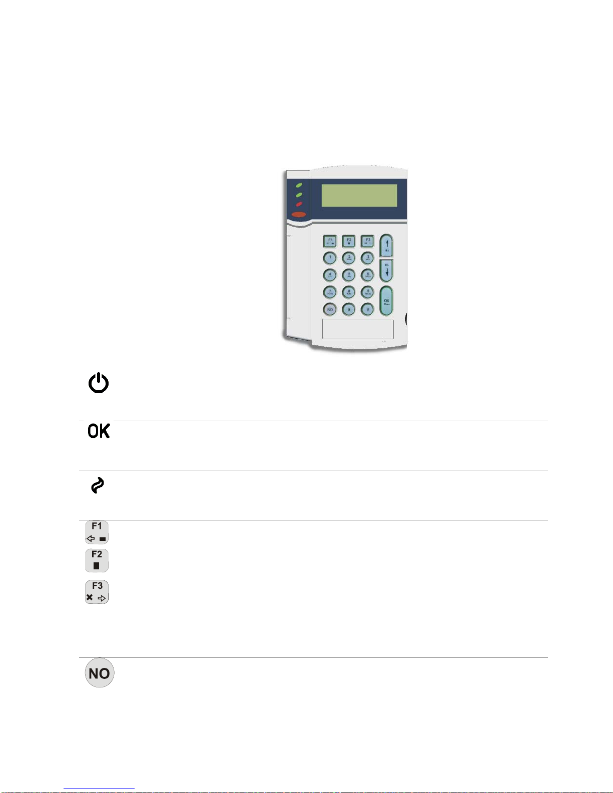
1.2 LCD keypad (CS5500)
The CS5500 LCD keypad allows you to program the CSx75 system using a menu
structure.
Power (green)
Ready (green)
Fire (red)
Function keys
Press
No
• On if the system is connected to the mains and the battery is OK.
• Flashes if the system has no battery or a low battery.
•
• On when the system is ready to arm.
•
• Off when the system cannot be armed.
• On when a fire zone has been activated.
• Flashes when there is a probl em wi t h a fire zone.
• Off when all fire zones are operating correctly.
• Press F1 to scroll to the start of the LCD message.
• Press F3 to scroll to the end of the LCD message.
In multi-area mode, these keys have specific functions. If you select one
or more areas in this mode:
• Press F1 to part arm the set of are as .
• Press
• Press F3 to disarm the set of areas.
You can program these keys to perform a function when not in multiarea mode. To do this, select Installer Menu>This Keypad>Function
Keys. For more information on navigating the menus, see page 9.
• Cancel a change to the menu selection or
• Navigate to a higher level in the menu structure or
• Cancel a sequence when entering numeric data.
if the system is not connected to the mains.
Off
Flashes
when the system is ready to force arm.
to full arm the set of areas.
F2
to:
No
Page 8
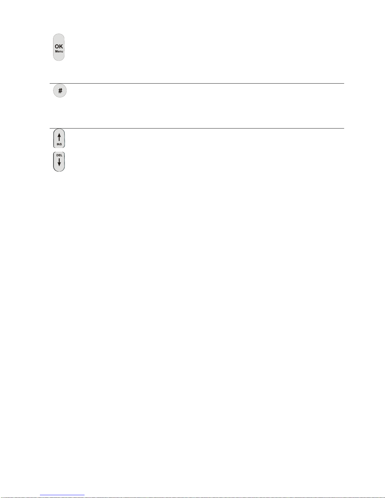
OK Press OK to:
Activate the menu
•
Hash
Navigation ke ys Press the navigation keys to scroll through menu lists and options.
• Accept selection changes
• Move forward in the menu structure or
• Complete a sequence when entering numeric data.
When editing text and phone numbers:
• Press
• Press # F3 to move to the last character or number.
• Press # to delete from the current position to the last character
or number.
When in multi-area mode or not in a menu:
• Press to display bypassed zones.
• Press to display problem zones.
When editing text and phone numbers:
• Press to overwrite or insert text.
• Press to delete text.
to move to the first character or number.
# F1
1.3 Other methods of programming
You can use the CS5500 keypad to program the system without the menu system. This
mode uses devices, locations and segments.
or
or
To program in this mode using the CS5500 keypad:
• Use the OK/Menu key instead of the * key.
• Use the F2 key instead of the Exit key.
To access this mode, select Installer Menu>Commands>Device/Location Programming.
For more information on navigating the menu, see page 9.
You can also program the system using UDx75 software. For more information, see page
16.
The recommended programming method is to use the menu structure rather
than devices and locations.
Page 9

2 PROGRAMMING THE SYSTEM
2.1 Powering up the system
When the CS5500 if powered up for the first time, the language, keypad defaults, partition
and keypad must be set. These options must also be set each time a keypad is defaulted.
• The language option sets the first language of the keypad.
• The keypad defaults option sets the country specific keypad defaults. It does not
default the keypad.
• The partition and keypad options set the keypad address.
Use the navigation keys to scroll between the different options and press OK to select an
option. See Navigating the menus for more information.
2.2 Entering programming mode
Your installer code allows you to program the system through the installer menu. There
are two levels in the installer menu. The light menu contains the most important options
and the advanced menu contains additional options.
1. Press OK at the system prompt and enter your installer code. For a list of default
codes, see page 6.
2. Use the µ¶ keys to navigate the menu. The full menu map can be found in the
Menu Structure included in your language kit. The light menu is in green text and the
advanced menu is in black text.
3. Select OK to select an option or use the numerical/character keys to edit the existing
option.
Enabled. The keypad displays the advanced menu until this option is disabled.
To switch to the advanced menu, navigate to Commands>Advanced and select
2.2.1 Changing the user interface language
1. Press OK at the system prompt.
2. Press OK again to display the system prompt in a different language.
3. Press OK until you find the language you require.
4. Continue using the keypad as normal.
2.3 Navigating the menus
• Press the µ¶ keys to scroll through menu lists and options.
• Press # µ to move to the same menu item for the previous option. For example, if
you are in a submenu for zone 2, press # µ to move to the same submenu for zone
1.
• Press # ¶ to move to the same menu item for the next option. For example, if you
are in a submenu for zone 2, press # ¶ to move to the same submenu for zone 3.
The keypad may timeout from the menu system and return to the default display.
2.3.1 Command menu
You can access a limited number of menu options without entering your installer code.
This opens the command menu.
Page 10

4. Press OK at the system prompt.
5. Press the µ¶ keys to enter and navigate the command menu.
2.4 Selecting a menu option
• Press OK to select a menu option and move forward in the menu structure.
• Press NO to reject a menu option and move backwards in the menu structure.
• Press F1 to move through the second line of the LCD display, one word at a time,
from right to left.
• Press F3 to move through the second line of the LCD display, one word at a time,
from left to right.
2.5 Changing a menu option
The CSx75 has several editors that you can use to change the value of certain
programmable menu options. You can change selection list entries, binary entries, phone
numbers and text. This section describes how to change selection list entries, binary
entries, numeric entries and phone numbers. For information on changing text, see page
14.
2.5.1 Changing selection list entries
1. Navigate with the µ¶ keys to the relevant menu option and press OK.
2. The current value for the menu option is displayed, for example, Enabled.
3. Press the µ¶ keys to change the value, for example, change Enabled to Disabled.
4. Press OK to accept the change.
• If the new value is valid, the key pad beeps once to confirm the change and
returns to the menu option.
• If the new value is invalid, the keypad beeps three times to reject the change
and returns to the menu option.
5. Press NO to cancel the change and return to the menu option.
2.5.2 Changing binary entries
1. Navigate with the
2. The current value for the menu option is displayed, for example, 1 2 3 - - - - 8 means
that 1, 2, 3 and 8 are on (included) while 4, 5, 6 and 7 are off (excluded).
3. Press the corresponding numerical key to change a value, for example, press 1 to
change the state of 1 to off and press 4 to change the state of 4 to on. The display
changes to - 2 3 4 - - - 8.
4. Press OK to accept the changes.
If the new values are valid, the keypad beeps once to confirm the change and
returns to the menu option.
If the new value is invalid, the keypad beeps three times to reject the change and
returns to the menu option.
5. Press NO to cancel the changes and return to the menu option.
2.5.3 Changing numeric entries
1. Navigate with the
2. The current value for the menu option is displayed, for example, 55.
3. Do one of the following:
keys to the relevant menu option and press OK.
µ
keys to the relevant menu option and press OK.
µ
Page 11

• Press a number key to clear the current value and display the value of the key
pressed.
• Press µ to increase the current value by one.
• Press ¶ to decrease the current value by one.
• Press ## to clear the current value to 0.
4. Press the number keys to enter the value.
5. Press OK to accept the changes.
• If the new value is valid, the key pad beeps once to confirm the change and
returns to the menu option.
• If the new value is invalid, the keypad beeps three times to reject the change
and returns to the menu option.
6. Press NO to cancel the changes and return to the menu option.
2.5.4 Changing phone numbers and phone prefixes
1. Navigate with the µ¶ keys to the relevant menu option and press OK.
2. The current value for the menu option is displayed, for example, 4567999.
3. Do one of the following:
• Press µ to toggle between insert mode and overwrite mode (insert mode allows
you to insert new numbers and overwrite mode allows you to overwrite existing
numbers).
• Press ¶ to delete the number at the cursor position.
• Press
the end of the string.
4. Do one of the following:
• Press the keys 0 to 9 to insert new numbers.
• Press #1 to insert a star.
• Press #2 to insert #.
• Press #3 to insert a four-second delay.
• Press #4 to change to pulse dialling.
5. Press OK to accept the changes.
• If the new number is valid, the keypad beeps once to confirm the change and
returns to the menu option.
If the new number is invalid, the keypad beeps three times to reject the change
•
and returns to the menu option.
6. Press NO to cancel the changes and return to the menu option.
to delete all the numbers from the number at the cursor position to
#
2.6 Exiting the menu system
1. Press ## to display the OK to Exit prompt.
2. Press OK at this prompt to exit the menu system.
Page 12

2.7 Programming map
The highest level of the menu structure is outlined below. The full menu structure can be
found in the Menu Structure included in your language kit. It provides a complete
overview of all modules and programming entries and should be used as a reference tool
when programming the system. For a definition of each menu structure entry, see the
glossary at the end of this manual.
Installer Menu Enrol Modules
Control Panel Inputs
Outputs
Codes
Communications
Partition Settings
System Settings
Arm Schedules
Home Automation
Model
Version
Country Code
Default Settings
This Keypad Keypad Features
Function Keys
X-10 Devices
Copy Keypad
Text
Partition
Keypad Number
Keypad Defaults
Model
Version
Default Settings
Other Keypads (1-8)
RF Receivers RF Receiver n
CS208/CS216 Input Expanders Input Exp n
CS507 Output Expanders Output Exp n
CS586 Direct Connect Module Files
Options
CS534 Listen-in Module Feature Select
Call Back Code
Line Hold Digit
Wrong PIN Digit Entries
Rings to Answer
Timers
Volumes
X-10 Devices
Model
Version
Default Settings
CS320 Power Modules Power Module n
Page 13

CS535 Voice Module Recording
Playback
Handshake Digit
Kiss Off Digit
Model
Version
Default Settings
CS1700 Proximity Readers Prox Reader n
CS7001 GSM Module Central Station
Autotest
GSM Options
Model
Version
Default Settings
Commands Alarm Memory
Reset Smoke Detector
Service Check
Do Self Test
Event Log
Outputs
Device/Location Programming
Advanced Menu
Page 14

3.1 Overview
The CSx75 has a text editor that includes a word library. You can use this editor to
change the text of certain programmable text options.
1. Navigate with the µ¶ keys to the relevant menu option and press OK.
2. Press OK to select the language you want to edit. See page 9 for more information.
3. The current text for the menu option is displayed, for example, Zone 2.
4. Do one of the following:
5. Press the keys 0 to 9 to insert new characters. Each key cycles through lower case
6. Press OK to accept the changes. The keypad beeps once to confirm the change and
7. Press NO to cancel the changes and return to the menu option.
3 EDITING TEXT
• Press µ to toggle between insert mode and overwrite mode (insert mode allows
you to insert new text and overwrite mode allows you to overwrite existing text).
• Press ¶ to delete the character at the cursor position.
• Press #¶ to delete all the characters from the character at the cursor position to
the end of the string.
and then upper case characters.
returns to the menu option.
3.1.1 Example
To change a zone name from Zone 2 to Upstairs:
1. Navigate to Zone 2 and press OK.
2. Press #F1 to go to the start of the zone name.
3. Press #¶ to delete all the characters.
4. Press 8 four times to enter the upper case letter ‘U’.
5. Press 7 once to enter the lower case letter ’p’. Continue until you have entered the
new zone name.
6. Press OK to save your changes.
3.2 Word library
The word library is a predefined collection of words that speeds up text editing. As you
type a character, the keypad automatically displays a matching word. The word library is
enabled by default. For a complete list of words in the word library, see page 46.
A flashing cursor highlights the character you are editing.
Press F2 to toggle flashing on the current character.
Press #F2 to toggle flashing on the current word.
Each character key cycles through lower and upper case letters and language
specific characters.
• To accept the word, press F3. The cursor moves to the end of the new word and you
can continue to enter text.
Page 15

• To accept a shortened version of the wor d, press F3 to accept the word. Then move
the cursor to the unnecessary characters and press ¶ to delete them.
• To reject the word, continue entering text as normal.
• Press the µ¶ keys to scroll through the list of word library words.
• To disable the word library:
1. Navigate with the µ¶ keys to Word Library and press OK.
2. The current state of the word library is displayed. In this case, it is enabled.
3. Use the µ¶ keys to change the state to disabled and press OK.
4. The keypad beeps once to accept the change and returns to Word Library.
3.3 Installer message
Up to four messages can be displayed on the LCD when the keypad is idle or when it
times out from a menu. If you enable more than one message, the messages are shown
in a continuous cycle.
• Installer message
You can define a message of up to two lines long that is displayed by default. You
can enable or disable this message.
• Date and time
The current system date and time. You can edit, enable or disable this message.
• Service required
A service message that is displayed when a system fault occurs. You cannot edit
this message but you can enable or disable it.
•
System ready/not ready
The status of the system. You cannot edit or disable this message.
To enable the installer message:
1. Navigate with the µ¶ keys to This Keypad and press OK.
2. Select Keypad Features>Display and press OK.
3. Scroll to Custom Message and press OK. The current status of the installer
message is displayed. In this case, it is disabled.
4. Use the µ¶ keys to change the status to enabled and press OK.
5. The keypad beeps once to accept the change and returns to Custom Message.
Page 16

4 PROGRAMMING WITH THE UDX75 SOFTWARE
4.1 Other methods of programming
You can program the system using the CS5500 keypad or the UDx75 software. This
software allows you to download the programming information on the control panel to the
computer running the UDx75 software, change it and upload the changes from the
computer to the panel. It also allows you to view the program log and event log. To
program the system using this software, you must connect the control panel to the
computer.
4.2 Connecting the panel to the computer
You can connect the control panel to the computer either directly via the RS232 serial
port or remotely via a modem.
4.2.1 Connecting using a serial port
Connecting via a serial port is useful if you are on site and want to connect directly to the
alarm system.
The connection to the CS275, CS575 or CS875 panel is made through the RS232 port
using CS590 cable.
The CS175 does not have an RS232 port. The connection to the CS175 is made through
the CS586 module, which provides a standard RS232 bi-directional DB-9 connector. The
CS586 can be used as a programming tool on any panel, as it is connected to the data
bus. It stores control panel settings that can be up/downloaded using the keypad or a
computer. For more information on reading data from the CS586, see the Installation
Manual.
To use the UDx75 software with a direct connection:
1. Double click the icon for the software or click Start>Programs>UDX75>UDX75.
2. The UDX75 window and the UDX75 Master access screen open.
3. Enter the operator name and password and click OK.
4. The UDX75 Operator access screen opens.
5. Enter the current operator and password and click OK.
6. To connect to the panel directly via the serial port, select Download>Connect>Direct
connect. The Connecting message box opens.
7. To connect to the panel via a TCP/IP network, select Download>Connect>Connect
TCP/IP. The Reserved (TCPIP) screen opens. Enter the TCP/IP address and click
.
OK
8. When you are finished uploading or downloading, select Download>Disconnect.
The default operator is Aritech and the default password is
1278. You may have to enter this twice.
4.2.2 Connecting using a modem
You can connect the control panel to the computer remotely via a modem. This can be
useful if you are not on site and want to connect to the alarm system.
You can connect normally or connect using answering machine defeat (AMD). If you use
AMD, the automatically timed two-call-answer-machine-defeat sequence is used.
Page 17

To use the UDx75 software with a modem connection:
1. Follow steps 1 - 5 on page 16.
2. Make sure that the modem settings are correct. For more information about modem
settings, see the UDx75 Online Help.
3. Select Download>Connect> Connect Using AMD.
4. A message box opens saying Initializing modem.
5. The computer connects to the panel.
6. When you are finished uploading or downloading, select Download>Disconnect or
click the Disconnect icon.
4.3 Programming with up/download software
Downloading allows you to read the existing programming data or the event log from the
control panel. Uploading allows you to send programming data, that you have set up
using the UDx75 software, from the computer to the control panel.
Before you download or upload information, do the following:
1. Ensure that the relevant control panel options are programmed correctly. There are
a minimum number of options that you must set before you can program the control
panel using the up/download software. Table 2 lists the options and the values to
enter.
2. Ensure that the up/download access code is the same in both the up/download
software and the control panel. See Table 1 for the correct default code.
3. If you are connecting remotely, make sure that the modem settings are correct. For
more information about modem settings, see the UDx75 Online Help.
4. Connect to the panel via the serial port or modem.
5. Select Download>Read all to download all the data from the control panel. The
computer downloads the data from the panel.
6. Select Download>Send all to upload all the data to the control panel. The computer
uploads the data to the panel.
The data that is downloaded and the downloading speed depend on the Send All/Read
All settings. The default number of strings sent to the keypad is 192 but it is possible to
limit the number of strings sent. If the default number is reduced, download time
decreases. For more information on setting up/download options, see the UDx75 Online
Help.
Keypad menu option Value
Serial Port>Connection Type
Serial Port>Speed 9600 Baud
Home Automation>Protocol Binary
Home Automation>Transition Broadcasts
Home Automation>Commands/Requests Ensure all options are set to On. This is the default state.
Home Automation
Ensure all options are set to Off. This is the default state.
Table 2 Required settings for up/downloading
Page 18

4.3.1 Programming tasks
You can perform all available programming tasks using the UDx75 software. Table 3
shows the UDx75 menu path for each task.
Task UDx75 menu option
Adding customer notes
Adding operators Program>Setup>Add/Change operators
View>Customers>Notes
Backing up the database
Changing a customer record
Changing a master or operator password Program>Change pass word
Changing operator rights
Changing the additional phone settings View>Control panel (Additional phone settings tab)
Changing the communicator codes Advanced>4+2 Codes
Changing the download options
Changing the partitions View>Control panel (Partition tab)
Changing the report settings View>Control panel (Phone numbers tab)
Changing the system 1 settings
Changing the system 2 settings View>Control panel (System 2 tab)
Changing the system 3 settings View>Control panel (System 3 tab)
Changing the UDx75 settings
Tools>Backup database
View>Customers>Single customer
Program>Setup>Add/Change operators
Program>Setup>Download options
View>Control panel (System 1 tab)
Program>Setup>Program setup
Changing the user arm/disarm codes View>Control panel (Codes tab)
Compacting the database Tools>Compact database
Connecting via the modem
Connecting via the serial port
Copying a customer’s panel settings
Deleting a customer record View>Customers>Single customer
Deleting the event log
Downloading
Downloading and updating the device list Download>Device list>E nroll devic es
Downloading the event log
Exporting a database
Download>Connect >Connect or Download>Connect
>Connect us ing AMD
Download>Connect>Direct connect
Program>S etup>Copy options
Download>Event log>Delete Event log
Download>Send all
Download>Event log>Read entire log
Tools>Export database
Page 19

Task UDx75 menu option
Importing a database
Tools>Import database
Loading the default settings Advanced>Default Cont rol data
Logging in
Printing a customer record list
Start>Programs>UDX75>UDX75
Program>Print preview>Customer list
Printing a program log Program>Print preview>Program log
Printing a programming worksheet
Printing an operator list
Program>Print preview>Programming worksheet
Program>Print preview>Operator list
Printing cus tomer notes Program>Print preview>Notes
Printing the event log
Programming the CS1700
Program>Print preview>Event log
Expanders>CS1700>1
Programming the CS208/CS216 View>Control panel (Zones tab)
Programming the CS320
Programming the CS507
Expanders>CS320>1
Expanders>CS507>1
Programming the CS534 Expanders>CS534
Programming the CS535
Expanders>CS535
Programming the CS7001
Expanders>CS7001
Programming the keypad text Expanders>Keypad text
Programming the keypads
Programming the wireless receivers
Expanders>Keypad options>Partition 1>Keypad 1
Expanders>Wireless>1
Programming the zones View>Control panel (Zones tab)
Repairing the database
Restoring the database
Tools>Repair database
Tools>Restore database
Retrieving and viewing a customer record View>Customers>Single customer
Running diagnostics
Setting auto call back options
Tools>Diagnostics
Program>Setup>Auto callback
Setting customer account options View>Customers>Account options
Setting the country and language
Setting the download access
Program>Setup>Country/Language
Advanced>Download options
Setting the format overrides Advanced>Format overrides
Page 20

Task UDx75 menu option
Setting the outputs
Advanced>Auxiliary outputs
Setting the TCP/ IP sett i n g s Program>Setup>TCP/IP Settings
Setting the timed functions
Setting the zone type
Advanced>T imed functions
Advanced>Zone types
Setting up a customer record View>Customers>Single customer
Setting up a modem
Setting up answering machine defeat
Program>Setup>Modem setup
Program>S etup>AMD setup
Specifying the direct connect settings Program>S etup>Direct connect settings
Specifying the serial port settings
Switching operators
Advanced>Ser ial port settings
Program>Next operator
Uninstalling the software Start>Settings>Control Panel
Uploading
Viewing a customer record list
Download>Read all
View>Customers>List
Viewing an operator list Program>Setup>Add/Change operators
Viewing the auto answer failures
View>Customers>Auto answer failures
Viewing the control panel settings
View>Control panel
Viewing the event log Download>Event log>Read entire log
Viewing the keypad status
View>Keypad status
Table 3 UDx75 menu paths
Page 21

5 ADVANCED PROGRAMMING
5.1 Multi-area mode
You can program a keypad to act as a single-area keypad or a multi-area keypad by
default. A single-area keypad allows the user to arm one area only while a multi-area
keypad allows the user to arm one or more areas. A user with rights can change a singlearea keypad to a multi-area keypad and vice versa.
1. Navigate with the µ¶ keys to Multi-Area Keypad and press OK.
• Select Enable to set the keypad as a multi-area keypad by default.
• Select Disable to set the keypad as a single-area keypad by default.
2. Press OK to save the setting.
3. The keypad beeps once to confirm the change and returns to Multi-Area Keypad.
5.2 Copying zones
You can copy the settings for the current zone to another zone or a set of other zones. All
the zone settings (except the user defined zone name and RF settings) are copied to the
target zones.
1. Navigate with the µ¶ keys to Copy Zone and press OK.
2. The keypad prompts you to enter the start zone.
3. Enter the number of the first zone to which the settings will be copied and press OK.
4. The keypad prompts you to enter the end zone.
5. Enter the number of the last zone to which the settings will be copied and press OK.
5.3 Modifying existing zone types
You can change the input type, name, attributes, sound and reporting features of an
existing zone type. The following steps describe how to change the input type.
1. Navigate with the µ¶ keys to Zone Types and press OK.
2. Scroll to the zone type to be modified and press OK.
3. To change the input type of the selected zone, navigate to Input Type and press OK.
4. Use the µ¶ keys to select an input type that you want to enable/disable for the
selected zone type and press OK.
5.4 Setting up a keypad to use multiple languages
You can set several languages on the keypad.
1. Navigate with the µ¶ keys to This Keypad and press OK.
2. Scroll to Text>Set Languages and press OK.
3. The current language is displayed as Language 1.
4. Scroll to Language 2 and press OK. If no language 2 is set, a blank line is displayed.
5. Use the µ¶ keys to select the second language and press OK.
6. The keypad beeps once to accept the change and returns to Set Languages.
7. Press NO to cancel the change and return to Set Languages.
Page 22

8. Repeat these steps to set other languages.
5.5 Setting up a communicator
The CSx75 supports different modes of reporting events to multiple central stations.
There are six phone numbers - each phone number has it own account code, protocol
and events. The configured prefix is common to all six phone numbers. If a four-second
delay is specified in the prefix, the panel does not look for a dial tone, but performs blinddialling. The following scenarios are examples of how to set different modes of reporting.
5.5.1 Reporting to one phone number
The control panel reports events to one central station only. You specify settings for
phone number 1. Events for phone number 1 are enabled by default.
Level 1 Level 2 Value State
Phone Number
Phone Number 2
Account Code Phone Number 1 445566
Phone Number 1 123456
Protocol
Phone Number 2
Events
Phone Number 1 – Alarm Restores
Phone Number 1 – Tampers and Restores Enabled
Phone Number 2 – Alarms
Phone Number 2 – Alarm Restores
Phone Number 2 – Tampers and Restores
Phone Number 2
Phone Number 1 SIA
Phone Number 1 – Alarms
Enabled
Enabled
5.5.2 Backup reporting
Backup reporting configures the control panel to report to two or more central stations.
The first phone number belongs to the main central station and all other phone numbers
belong to the backup central stations. Events are reported to the first number but, if the
panel cannot reach this number, it dials the backup number(s). The control panel makes
two calls to each number in sequence. It performs the sequence for the number of times
specified in ARC Dial Attempts or until it receives a kiss off. The same account code is
used to report to all numbers. Events for phone number 1 are enabled by default and
events for phone numbers 2 - 6 are disabled by default. If phone number 1 and phone
number 2 are programmed, the default sequence is 1,1 2,2 1,1,2,2 for a total of eight
calls to each number.
Level 1 Level 2 Value State
Phone Number
Phone Number 2 456789
Phone Number 1 123456
Page 23

Level 1 Level 2 Value State
Account Code
Phone Number 2 445566
Phone Number 1 445566
Protocol
Events Phone Number 1 – Alarms Enabled
Phone Number 1 – Alarm Restores
Phone Number 1 – Tampers and Restores
Phone Number 2 – Alarms Disabled
Phone Number 2 – Alarm Restores
Phone Number 2 – Tampers and Restores
Phone Number 1 SIA
Phone Number 2 SIA
Enabled
Enabled
Disabled
Disabled
5.5.3 Dual reporting
Dual reporting configures the control panel to report to two different central stations.
Events must be reported to both phone numbers. The control panel dials the first number
twice. If it cannot reach this number, it dials the second number twice. It performs this
sequence for the number of times specified in ARC Dial Attempts or until it reports the
events to both numbers. The same account code is used to report to both numbers.
Events for phone number 1 are enabled by default and events for phone number 2 are
disabled by default.
Level 1 Level 2 Value State
Phone Number
Phone Number 2 456789
Account Code
Protocol Phone Number 1 SIA
Events
Phone Number 1 – Alarm Restores Enabled
Phone Number 1 – Tampers and Restores
Phone Number 2 – Alarms
Phone Number 2 – Alarm Restores Enabled
Phone Number 2 – Tampers and Restores
Phone Number 1 123456
Phone Number 1 445566
Phone Number 2 445566
Phone Number 2 SIA
Phone Number 1 – Alarms
Enabled
Enabled
Enabled
Enabled
Page 24

5.5.4 Split reporting
Split reporting configures the control panel to report to two different central stations.
Some events must be reported to phone number 1 and others to phone number 2. The
control panel dials the first number twice. If it cannot reach this number, it dials the
second number twice. It performs this sequence for the number of times specified in ARC
Dial Attempts or until it reports the relevant event to each number. The same account
code is used to report to both numbers. Events for phone number 1 are enabled by
default and events for phone numbers 2 are disabled by default.
Level 1 Level 2 Value State
Phone Number Phone Number 1 123456
Account Code
Phone Number 2 445566
Protocol
Events Phone Number 1 – Alarms Enabled
Phone Number 1 – Alarm Restores
Phone Number 1 – Tampers
Phone Number 2 – Alarms Disabled
Phone Number 2 – Alarm Restores
Phone Number 2 – Tampers and Restores
Phone Number 2 456789
Phone Number 1 445566
Phone Number 1 SIA
Phone Number 2 SIA
Enabled
Disabled
Disabled
Enabled
Page 25

6 PROGRAMMING A SAMPLE SYSTEM
6.1 The sample system
This chapter explains how to program a basic system using the tasks and settings
outlined in Table 4. More information on installing a basic system can be found in the
Installation Manual. Enter 1122 to silence the keypad if it starts beeping during
programming.
Task Programming information
Setting up the system
Setting the keypad partition and keypad number Partition 1
Setting the system date and time Master user code
Enrolling the system modules
Defaulting the panel Module 0
Defining the country code
Configuring the system
Configuring the keypads Partition 1
Configuring zones 4 hardware zones:
Configuring the phone settings Phone number: 0852525
Programming the wireless modules
Defaulting the wireless modules RF receiver module 32
Programming the wireless detectors 2 zones:
Keypad 1
Keypad 2
Zone 1 is an entry/exit zone.
Zone 2 and 3 are burglary zones.
Zone 4 is a fire zone.
Account Code: 112233
Protocol: SIA
Zone 9 is a door/window sensor burglary zone.
Zone 10 is a PIR detector burglary zone.
Table 4 A sample system
6.2 Setting up the system
When you have installed the system, select the user interface language. For more
information on changing the language, see page 9.
6.2.1 Setting the keypad partition and keypad number
You must set the partition and keypad number for the current keypad. The keypad can
connect to the bus only after you set these numbers.
1. The keypad prompts you to enter the partition number for the current keypad.
Page 26

2. Enter the partition number an d p ress OK. In this case, enter 1.
3. The keypad prompts you to enter the keypad number.
4. Enter the keypad number and press OK. In this case, enter 1.
5. The system prompt appears.
6. Repeat the above steps for each keypad connected to the system.
The partition number and keypad number prompts are displayed for the initial
setting only. To change these numbers again, scroll to This Keypad>Partition and
This Keypad> Keypad Number.
6.2.2 Setting the system date and time
You must enter a master user code to set the system date and time. For a list of master
codes, see page 6.
1. Press OK at the system prompt.
2. Enter the master user code.
3. Scroll to Options>Set Date/Time and press OK.
4. The curr ent time is s hown as day of the week, hours and minute s (ww.hh.mm). The
current date is shown as month, day and year (mm.dd.yy).
5. Press the µ key to increase the hour or press the ¶ key to decrease it.
6. Press OK to accept th e changes and move the cursor forward.
7. When you have finished updating the date and time, press ## to return to the system
prompt.
6.2.3 Enrolling the system modules
When you select the enrol modules process, new modules are enrolled on both the
control panel and the keypad. The keypad must enrol modules in order to display the
relevant menu options.
1. Press OK at the system prompt and enter your installer code.
2. Navigate with the µ¶ keys to Enrol Modules and press OK.
3. The keypad starts enrolling the modules. The Enrolling Modules message is no
longer displayed and a confirm beep sounds.
4. When the modules have been enrolled, the message changes to Modules Enrolled.
5. Verify the enrolled modules. Navigate with the µ¶ keys to Commands and press
.
OK
6. Scroll to Event Log and press OK. When the control panel enrols a module, it adds
an enrol event to the event log. This event contains the module number. Scroll
through the event log to verify that each module has been enrolled.
6.2.4 Defaulting the panel
Each module can be defaulted. It is recommended that you default each module before
modifying its settings.
1. Navigate with the µ¶ keys to Default Settings in the relevant module menu and
press OK. In this case, sele ct Control Panel>Default Settings to restore the default
control panel settings.
2. A confirmation message is displayed. Press OK to accept the default settings.
3. The keypad sounder beeps once to confirm the reset.
Page 27

6.2.5 Defining the country code
The control panel is shipped with software that contains different country default settings.
Changing the value or selecting a country code configures the panel with the
corresponding country defaults.
1. Navigate with the µ¶ keys to Country Code and press OK. The current country is
displayed.
2. Scroll through the countries and press OK to select the new country. For a list of
default country codes, see Table 1 on page 6.
6.3 Configuring the system
6.3.1 Configuring the keypads
You define keypad options for the current keypad. You can copy these settings to another
keypad. The keypad number and keypad partition are NOT copied.
1. Navigate with the µ¶ keys to This Keypad>Keypad Features and press OK.
2. Scroll through the configurable options for the keypad. Press OK to change an
option.
3. Navigate with the µ¶ keys to Copy Keypad and press OK.
4. To copy the current keypad settings to another keypad, select To One Keypad and
select the partition number.
5. Scroll to the keypad to which you want to copy the settings and select OK. In this
case, select Keypad 2 and press OK to copy the settings for keypad 1 to keypad 2.
6. To copy the settings to all other keypads, select To All Keypads. Press OK to copy
the settings.
6.3.2 Configuring zones
You can program a zone to be one of 20 different zone types.
1. Navigate with the µ¶ keys to Control Panel>Inputs>Zones and press OK.
2. A list of all zones is displayed. Select the number of the zone that you want to
configure and press OK.
3. Scroll to Zone Type and press OK.
4. Select the relevant zone type and press OK.
• In this case, select Zone 1>Zone Type and press OK. Select entry/exit and
press OK.
• Press # ¶ to move to Zone 2>Zone Type. Set the zone type to burglary.
• Press # ¶ to move to Zone 3>Zone Type. Set the zone type to burglary.
• Press # ¶ to move to Zone 4>Zone Type. Set the zone type to fire.
6.3.3 Configuring the phone settings
You specify the phone number, the account number and the communication protocol that
are used to send reports to the central station.
1. Navigate with the µ¶ keys to Control Panel>Communications>Central
Station>P hone Numbers and p ress OK.
2. Select the relevant phone number.
3. Scroll through the configurable options for that phone. Press OK to change a setting
for an option. For more information, see Setting up a communicator on page 22.
•
In this case, select Phone 1 and press OK.
Page 28

• Scroll to Phone Number and press OK.
• Press #¶ to clear the current value.
• Enter 0852525 and press OK.
• Scroll to Account Code and press OK.
Press #¶ to clear the current value.
•
• Enter 112233 and press OK.
• Scroll to Protocol>SIA and press OK.
6.4 Programming the wireless modules
6.4.1 Defaulting the wireless modules
You must default each module before you start programming it. For more information on
the DIP switch settings on the receiver, see the Installation Manual.
1. Navigate with the µ¶ keys to RF Receivers and press OK.
2. Select the relevant module bus ID and press OK. In this case select RF Receiver 32
and press OK.
3. Select Default Settings and press OK.
4. A confirmation message is displayed. Press OK to accept the default settings.
5. The keypad sounder beeps once to confirm the reset.
6.4.2 Programming the wireless detectors
1. Navigate with the µ¶ keys to RF Receivers and press OK.
2. Select the relevant module bus ID and press OK. In this case select RF Receiver 32
and press OK.
3. Scroll to Start Zone and press OK.
4. Enter the starting zone of the receiver. In this case, enter zone 9 to set zone 9 as the
starting zone for receiv er 32.
5. Scroll to Learn-in Mode and press OK.
6. To learn-in more than one device, scroll to Sequential Programming, select Yes and
press OK.
7. Scroll to Start Learning and press OK.
8. Enter the zone number to start with. In this case, enter 9 to program the detectors in
zones 9 and 10 and press OK.
9. Tamper the different detectors in sequence.
• In this case, tamper the door/window sensor burglary zone. A ding-dong
confirms t hat the detector in zone 9 has been learned in.
• Tamper the PIR detector. A ding-dong confirms that the detector in zone 10 has
been learned in.
10. Press ## to leave the programming mode. The OK to Exit prompt is displayed. The
system now functions as a normal alarm system. See the CS5500 LCD Keypad User
Manual for information on arming and disarming the system.
Page 29

7 READING THE EVENT LOG
The event log dis p lay s t he det ai l s of al l the ev ents that occur fr om whe n y ou t urn the
system on. A maximum of 512 events are held in the event log. For a list of all possible
events, see page 46.
To read the event log:
1. Press OK at the system prompt and enter your installer code.
2. Navigate with the µ¶ keys to Commands and press OK.
3. Scroll to Event Log and press OK.
4. The last event to be added to the log is shown. The > symbol indicates that the
message must be scrolled horizontally.
5. Press F3 to scroll to the right and view the rest of the event description. Table 5
explains each part of the event description.
Alarm 3 Press F3 Alarm 3
168 17:32 >
• In this case, an alarm occurred in zone 168 in partition 3 at 17:32. No report
was sent to the central st ation. The event occurred on September 25. This is
the twenty-eighth event in the log.
6. Press the µ¶ keys to scroll through the events in the log.
Event description Explanation
L1
L2
EventType The type of event that occurred.
PN
PartitionName
Zone/User Name The zone name or user name.
UN/ZN
HH:MM
25/9 028
EventType PN PartitionName
Zone/User Name UN/ZN HH:MM DD/MM LOG
The number of the partition in which the event occurred.
The name of the partition in which the event occurred.
The user number, zone number or device number.
The hour and the minute the event occurred.
DD/MM
LOG
The day and month the event occurred.
The position of the event in the event log.
Table 5 Event de scription
Page 30

8 REFERENCE
8.1 Appendix 1: Reporting fixed codes in Contact ID or SIA
Table 6 lists the event codes sent for different reports (if enabled) when using Contact ID
or SIA formats. The numbers in brackets following the event is the number that is
reported as the zone number. If there are no parentheses, the zone is 0. An asterisk
represents the first character from the event code of the zone that is bypassed or in
trouble.
Report Contact ID SIA Report Contact ID SIA
Manual test 601 RX Keypad tamper 137 TA
Autotest
Open (user number)
Close (user number) 401 CL Duress 121 HA
Cancel (user num b e r )
Download complete
Start program 627 LB RF sensor lost (zone
End program 628 LX RF sensor restore (zone
Recent close (user
number)
Exit error (user number) 457 EE Sensor battery restore (zone
Event log full 605 JL Zone trouble (zone number) 380 *T
Fail to communicate
602 RP
401 OP
406 OC
412 RS
401 CR Sensor low battery (zone
354 RT
Keypad panic(audible)
Keypad panic (silent)
Keypad auxiliary 1
Keypad auxiliary 2
number)
number)
number)
number)
Zone trouble restore (zone
number)
120 PA
121 HA
110 FA
100 MA
381 *T
381 *R
384 XT
384 XR
380 *R
Expander trouble
(device number)
Expander restore
(device number)
Telephone fault
Telephone restore
Siren tamper (device
number)
Siren restore (device
number)
333 ET
333 ER
351 LT
351 LR
321 YA
321 YH
Zone tamper (zone number)
Zone tamper restore (zone
number)
Zone bypass (zone number)
Bypass restore (zone
number)
Near Alarm (A/B Alarm)
Early open/late close
137 TA
137 TR
570 *B
570 *U
138 BM
451 OK
Page 31

Report Contact ID SIA Report Contact ID SIA
Aux power over current
312 YP Partial close 456 CF
(device number)
Aux power restore
(device number)
Low battery (device
number)
Low battery restore
(device number)
Mains fail (device
number)
Mains restore (device
number)
Box tamper (device
number)
Box tamper restore
(device number)
312 YQ Zone activity fault 391 NA
309 YT Zone activity restore 391 NS
309 YR Fail to close 454 CI
301 AT RF jamming 344 XQ
301 AR RF jamming restore 344 XH
137 TA Smoke detector clean me 393 YX
137 TR Smoke detector clean me
393 YZ
restore
Table 6 Event codes
Page 32

8.2 Appendix 2: Overview of module numbers
Every keypad, expansion module and wireless receiver module has a module number.
Module Module number
CSx75 0
CS534 Two-way Listen-In
CS535
CS7001 78
64
77
Table 7 Module numbers
8.2.1 CS1700 door swipe module
Learn-in sequence Module number Learn-in sequence Module number
1 113 9 121
2 114 10 122
3
4 116 12 124
5 117 13 125
6
7 119 15 127
8 120
115
118
11
14
123
126
Table 8 CS1700 module numbers
8.2.2 Keypads
Keypad Part1 Part2 Part3 Part4 Part5 Part6 Part7 Part8
1 192 193 194 195 196 197 198 199
2
3
4
5
6 232 233 234 235 236 237 238 239
7 240 241 242 243 244 245 246 247
8
200 201 202 203 204 205 206 207
208 209 210 211 212 213 214 215
216 217 218 219 220 221 222 223
224 225 226 227 228 229 230 231
248 249 250 251 252 253 254 255
Table 9 Keypad module numbers
Page 33

8.2.3 CS208/CS216 input expander
DIP switch setting
Starting
zone
number
9 23
17 16
25 17
33 18
41 19
49 20
57 21
65 96
Module
number
DIP switch setting
Starting
zone
number
89 99
97 100
105 101
113 102
121 103
129 104
137 105
145 106
Module
number
73 97
81 98
= ON = OFF
8.2.4 CS208H input expander
DIP
switch setting
Starting
zone
number
9 23
17 16
25 17
33 18
153 107
161 108
Table 10 CS208/CS216 module numbers
Module
number
DIP switch setting Starting
zone
number
73 97
81 98
89 99
97 100
Module
number
Page 34

DIP
switch setting
Starting
zone
number
41 19
Module
number
DIP switch setting
Starting
zone
number
105 101
Module
number
= ON = OFF
49 20
57 21
65 96
Table 11 CS208H module numbers
113 102
121 103
8.2.5 CS507 output module
DIP switch setting Module number DIP switch setting Module number
24
25
26
28
29
30
= ON = OFF
27
Table 12 CS507 module numbers
31
8.2.6 CS320 power supply module
DIP switch setting Address DIP switch setting Address
= ON = OFF
84
85
86
87
Table 13 CS320 module numbers
88
89
90
91
Page 35

DIP switches 1-3 set the address of the CS320. DIP switch 4 controls the tamper feature.
On enables tamper. Off disables tamper.
8.2.7 RF433 receiver module
DIP switch setting
RF
receiver
1 34
Module
number
DIP switch setting
RF
receiver
5 38
Module
number
2 33
3 32
4 39
= ON = OFF DIP switch 4 is not used
8.2.8 RF868 receiver module
DIP switch setting
RF
receiver
1 34
2 33
3 32
(default)
Table 14 RF433 module numbers
Module
number
(default)
DIP switch setting
6 37
7 36
8 35
RF
receiver
5 38
6 37
7 36
Module
number
4 39
= C (ON) = O (OFF) DIP switch 4 is not used
8 35
Table 15 RF868 module numbers
Page 36

8.3 Appendix 3: Output events
The control panel, the CS507 output expander and the CS320 power module each have
selectable output events that trigger the output. Table 15 to Table 17 list these events.
# Event # Event # Event
Misc Keypads
Alarms
8
11 Duress 13 Keypad Medical 1 Fire Alarm
48
37 Program Mode 15 Keypad Tamper 3 Trouble Alarm
49 *
50 *
Tests 57 Silent Panic 17 Alarm Memory
29
52 Manual Test 25 Fire LED 5 Burglary Siren
16
59 Walktest Mode 40 Over-current 7 Any Siren
21 Armed 42 Siren Tamper
Any Bypass
Code Entry (Note 1)
Keyfob Funct 1
Keyfob Funct 2
Dyn Battery Test
Automatic Test
Arm/Disarm
12
14
47
56
Tampers and faults
39
41
Keypad Fire
Keypad Panic
Keypad Beeping
Audible Panic
Smoke Det Reset (Note
2)
Box Tamper
0
2
4
46
Sirens
6
60
Communications
Burglary Alarm
24-hour Alarm
Tamper Alarm
Any Alarm
Fire Siren
External Si re n
22
23 Ready to Arm 44 Any Short Circ’t 33 Line Seiz ure
24
53
54 Armed Stay 28 Expander Trouble 38 Downloading
30
31 Closed Period 10 Low Battery
18
19
20 Entry or Exit
Disarmed
Not Ready to Arm
Armed Away
Open Period
Entry
Exit
43
45
26
9
Any Open Circuit
Any Open/Short
Fire Trouble
Mains Failure
Table 16 Control panel ou tput events
32
35
36
55
Listen-in
Fail to Comm’ate
Phone Line Fault
Aux Comm Fail
Page 37

* Events 49 and 50 require RX8w8, RX16w8, RX32w8, RX8i4, RX16i4, or RX48i4
wireless receivers to operate.
If set to latched condition, these events are one second
1
When Event 48 is programmed, it is possible to program a user code's
authorization to select which output(s) a particular code activates.
2
Always program Event 39, Fire alarm reset, to follow the event.
.
# Event # Event # Event
Tampers Misc Communications
25
39 Over-current 11 Duress 33 Line seizure
40
41
42
26
28 Expander Trouble 51 CS507 Schedule 21 Armed
Fire LED
Box Tamper
Siren Tamper
Any Open Zone
Fire Trouble
8
45
36
46
47
Any Bypass
Code Entry
Program Mode
Keyfob Funct 1
Keyfob Funct 2
32
34
35
37
Arm/disarm
Listen-in
Failed to communicate
Telephone line fault
Download
9
10 Low Battery 53 X-10 Siren 23 Ready
Sirens Tests 24
5
6 Fire Siren 16 Automatic Test 31 * Closed schedule
7
Alarms 12 Manual Fire 19 Exit
0
1 Fire Alarm 14 Keypad panic 48 Auto arm control
2
3
4 Tamper Alarm 27 Chime
43
Mains Failure
Burglary Siren
Any Siren
Burglary Alarm
24-hour Alarm
Trouble Alarm
Any Alarm
52
29
Keypads 18
13
15
44
X-10 Alarm Mem
Dyn Battery Test
Keypad Medical
Keypad tamper
Keypad beeping
22
30 *
20
49
50
Not armed
Not ready
Open schedule
Entry
Entry or exit
Auto disarm control
Auto arm and dis a rm c ontrol
17 Alarm memory
Table 17 CS507 output expander output events
Page 38

* See Schedule Times>Opening and Schedule Times>Closing/Autoarm.
# Event # Event # Event
Alarms Arm/disarm Misc
17
Tests 22 Disarmed 7 Program Mode
3
Tampers 18 Entry Keypads
25
Alarm Memory
Dyn Battery Test
Fire LED
If set to latched condition, these events are one second
Events 46 and 47 require RX8w8, RX16w8, RX32w8, RX8i4, RX16i4, or RX48i4
wireless receivers to operate.
Events 48, 49 and 50 arm or disarm the CSx75 at the open (disarm) or close
(arm) time for the appropriate schedule.
For events 48 and 50, the keypad buzzer will sound one minute prior to auto
arm if the zone value is 1. If the zone value is 0, the keypad will not sound prior
to auto arm.
21
23
19
Armed
Ready to Arm
Exit
32
0
29
.
Code Entry
Always On
Keypad Fire
11 Sm o ke Det Reset 20 Entry or Exit 30 Keypad Medical
8
9
10 Siren Tamper 12 Burglary Siren 27 Chime
26
1 Mains Failure 14 Any Siren 4 Listen-in
2
Over-current
Box Tamper
Fire Trouble
Low Battery
24
Sirens 28
13
15
16
Table 18 CS320 power module output events
Not Ready to Arm
Fire Siren
Fire Sir Steady
Any Sir Temporal
31
Communications
5
6
Keypad Panic
Keypad Beeping
Line Seizure
Phone Line Fault
Page 39

8.4 Appendix 4: Communicator formats
One of several communicator formats can be used to transmit to the receiver connected
to phone number 1. Consult the instructions for your central station receiver to determine
which format is compatible. Table 18 lists the selectable communication formats.
# Format Description
1
2 SIA
Contact ID
3
4
5
6
7 4+2 with 1400/1900 Checksum parity
8
9 4+2 with 2300/1800 Checksum parity
10
11
12 Siren tone
13
14 Reserved
15
SIA with area modifiers
Voice dialler with handshake and DTMF kiss-off
Reserved
4+2 with 1400/1900 double round parity
4+2 with 2300/1800 double round parity
Fast format 8 channel
Fast format 16 channel
Reserved
Format over-rides (build your own format)
16 Reserved
17
18
19 XSIA
20
21- 255 Reserved
200 Baud FSK (France Only)
200 Baud FSK Reversed (France Only)
XSIA with area modifier
1
2 The voice dialer protocol does not generate an FTC (failure to communicate).
Table 19 Communicator formats
If you require a format other than those listed, set the override options in
Communications>Format Override to build the appropriate format. In addition,
select Format Override in Communications>Central Station>Phone
Numbers>Phon e Number n>Protocol.
Page 40

8.5 Appendix 5: Service messages
The keypad displays service messages as a result of manual and automatic tests. Table
19 lists each message and outlines the action you should take to resolve the problem.
Message Definition Action
Control
Box Tamper
There has been interference with the
control panel casing.
Ensure that the casing is mounted correctly
on a flat surface and is not damaged. If there
is no damage, close the casing securely.
Control
Fail to Comm.
Control
Loss of Time
Control
Low Battery
Control
Over-Current
Control
Phone Trouble
The control panel tried to send a message
to the central station but failed.
The control panel has had a total loss of
power and the clock must be reset.
The standby battery for the control panel
is low.
The control panel has detected an
excessive amount of current being drawn
from one of the outputs and has disabled
the output as a means of protection.
The phone line connected to the control
panel is not working properly.
Ensure that the phone line is connected
properly. Use a test phone to check that the
phone service is available. Ensure that the
central station phone number, account and
protocol options are correct.
Reset the system clock and date.
The battery may need replacing. This may
be a temporary condition caused by a long
power failure.
Check the system for wiring faults.
An overcurr ent message can be reset only
by triggering the siren correctly, for example,
by generating a tamper on a zone that
activates the sirens. This is a security
feature to ensure that the overcurrent
message has disappeared and the sirens
can work properly again.
Ensure that the phone line is connected
properly. Use a test phone to check proper
service.
Control
Power Trouble
Control
Siren Trouble
Expansion
Aux. Comm. Fail
Expansion
Box Tamper
Expansion
Low Battery
The mains power supply to the control
panel is missing.
The connection to the control panel’s
siren is broken.
A reporting module tried to send a
message to the central station but failed.
There has been interference with the
casing of an expansion module.
The standby battery in an expansion
module is low.
Reconnect the power supply and ensure it is
working properly.
Repair the open circuit.
Ensure that the phone line is connected
properly. Use a test phone to check that the
phone service is available. Ensure that the
central station phone number, account and
protocol options are correct. Check that the
module is connected and working.
Ensure that the casing is not damaged and
is mounted correctly on a flat surface. If
there is no damage, close the casing
securely.
The battery may need replacing. This may
be a temporary condition caused by a long
power failure.
Page 41

Message Definition Action
Expansion
Over-Current
The expansion module has detected an
excessive amount of current being drawn
Check the module for wiring faults.
from one of its outputs and has disabled
the output as a means of protection.
Expansion
Power Trouble
Expansion
Siren Trouble
Expansion
Trouble
Zone Problem,
Press OK
The mains po wer supply is not connected
to an expansion module power supply.
The connection to an expansion module’s
siren is broken.
An expansion module or keypad is not
reporting to the control p anel.
There is a problem with a zone or zones.
Press OK to identify the zone(s) and the
problem condition.
One of the following mes sages is
displayed when you press OK.
CleanMe
Lost
A specific smoke detector
(for example, DP721) is
dirty. The panel detects a
degree of poll u t i on in th e
chamber of the fire/smoke
detectors.
The system has not
received RF sensor
transmissions for a long
period of time. Depending
on how the system is
programmed, this
condition activates a
service report. In addition,
it may activate a tamper
alarm if armed.
Reconnect the mains powe r supply and
ensure it is working properly.
Repair the open circuit.
Ensure that the module is connected
properly to the control panel.
Clean the detection chamber of the smoke
detector.
Ensure that the wireless zone module is
receiving power and has not been tampered
with. Repair any faults.
Low Battery
Short Loss The system has not
Tamper
Trouble
An RF sensor battery is
low.
received RF sensor
transmissions for a short
period of time. This
condition prevents arming.
There is a probl em wi t h
the wiring.
There is a probl em wi t h
the wiring.
Table 20 Service messages
Replace the battery.
Ensure that the wireless zone module is
receiving power and has not been tampered
with. Repair any faults.
Check the zone and zone sensors for
damage and repair any faults.
Check the zone and zone sensors for
damage and repair any faults.
Page 42

8.6 Appendix 6: Tasks summary
Task Installer Master user User No code Condition*
Adjusting the LCD contrast
Answer an up/download call
Arm and disarm the system
Bypass a zone * * * If authority allows.
Configure home automation
devices
Control home automation
devices
Engineer tamper reset
Initiate an up/download call
Perform a configured test
Perform a service check
Perform a walktest
Program voice phone numbers
*
*
*
If enabled for
If authority allows.
* If enabled for use
master users.
without a code.
Reset fire detector
Set system date and time
Set user authority level
Set user codes
Switch to multi-area mode
View the alarm memory
View the event log
Table 21 System tasks
*
Only own code
All codes for
master user.
Page 43

8.7 Appendix 7: Event log events
Event message Explanation
Alarm An alarm has been tripped.
Alarm Restore
Autotest
B-Alarm A full alarm on a B zone type that is considered a burglary alarm.
Box Tamper
Box Tamper
Restore
Burglary
Burglary Restore See Burglary event message.
Bypass
Bypass Restore
Cancel The report to the central station has been cancelled. This occurs when a user enters
CleanMe A smoke detector is dirty.
CleanMe Resto re
See Alarm event message.
An autotest message was sent to the central station.
A box tamper.
See Box Tamper event message.
A burglary zone has been tripped.
A zone is bypassed.
See Bypass event message.
a code after an alarm.
See CleanMe event message.
Clock Set
Close (arm) Closing (arm) by a specific user.
Code Entry
Data Lost
Disarm from Alarm A user disarmed the panel during an alarm.
Duress
Early Open
End Download The end of an up/download.
End Prog
A user set the date and time.
The lock of the access reader has been triggered.
The lock can be triggered by an accepted proximity card or by an Egress switch. An
Egress switch is a button that can be press ed by a user to open the lock of t he door.
It can also be called Request-to-Exit (RTE). When the Code Entry option is
activated, the reader sends a log message to the control panel, indicating that the
lock has been triggered.
The panel has been unable to send alarm messages to the central station. The
panel tries to send these messages a number o f times as specified in the FTC (Dial
attempts before Fail to C ommunicate) . Any pending reportable events are lost.
A duress code entered by a user. An alarm message is sent to the central station.
A user disarmed the system before the open time specified in the panel schedules.
End programming. The installer left programming mode.
End Walktest
See Walktest event message.
Page 44

Event message Explanation
Enrolled
Modules are enrolled on the bus. The module numbers are recorded.
Exit Error An exit door remained open after the exit delay expired.
Expander Trouble
Expander Trouble
A problem with an expander module.
See Expander Trouble event message.
Restore
Expansion Event
Fail to
A bus device generated an event to report conditions not described by other events.
The control panel or module tried to send a message to a central station but failed.
Communicate
Fire A fire alarm has been tripped.
Fire Restore
First Open
See Fire event message.
The time at which the first area was opened.
Keypad Tamper A keypad tamper.
Last Close
Late Close
The time at which the last area was closed.
A user disarmed the system after the closing time speci fied in the pan el schedules.
Listen-in The start of a listen-in session.
Log Full
The event log is full and the events must be reported to the up/download software.
An event can also be sent to the central station.
Low Batt Restore
Low Battery
See Low Battery event message.
The standby battery for the control panel/expansion module is low.
Mains Fail Restore See Mains Failure event message.
Mains Failure
The 220 V has disappeared.
Manual Fire A manual fire alarm generated by pressing the keys 1 and 3 on the keypad.
Manual Test
A manual test call to the central station.
Medical (Aux2) A medical alarm generated by pressing the keys 4 and 6 on the keypad.
Open (disarm)
Opening (disarm) by a specific user.
Output An output has been activated or restored. The output number is logged. This is
linked to the output module number.
Output Restore See Output event message.
Output Trip
Over-current
Over-current
An output has been activated.
An excessive amount of current has been drawn from one of the outputs.
See Over-current event message.
Restore
Page 45

Event message Explanation
PA Panic Alarm
A personal attack alarm has been tripped.
Panic Keypad
Partarm
Partial Arm
A panic alarm generated by pressing the keys 7 and 9 on the keypad.
See Partial Arm event message.
Part arm of the system by a specific user.
Recent Closing An alarm occurred within five minutes of the panel being armed.
Re-exit
Reset
A special feature of false alarm preventing.
A user has manually reset a smoke detector.
RF Jam Restore See RF Jammed event mess age.
RF Jammed
RF Low Battery
RF Low Battery
RF jamming.
An RF transmitter has reported a low battery.
See RF Low Battery event message.
Restore
Service End End of the ‘Installer on-site’ (service mode).
Service Start
Silent Panic
Start of the ‘Installer on-site’ (service mode).
A silent panic alarm.
Siren Tamper A siren tamper.
Siren Tamper
See Siren Tamper event message.
Restore
Start Download
Start Prog
The start of an up/download.
Start programming. The installer entered programming mode.
Tamper A tamper.
Tamper Restore
Telephone Fault
Telephone Fault
See Tamper event message.
Telephone line faults.
See Telephone Fault event message.
Restore
Trouble A trouble condition.
Trouble Restore
Walktest
Zone Inactive
See Trouble event message.
The start/end of a walktest.
See Zone Inactivity event message.
Restore
Zone Inactivity A zone inactivity monitori ng ev ent.
Page 46

Event message Explanation
Zone Lost
An RF transmitter has lost the supervision with the wireless receiver. This happens
when the transmitter has not reported its supervision message to the RF receiver
within the long supervision window. See appendix 5.
Zone Lost Restore
See Zone Lost event message.
Table 22 Event list
8.8 Appendix 8: Word library words
Alarm Delay Exterior House Microwave Room Smoke Up
Area Den Fire Infrared Motion Rumpus Sound Utility
Audio Detector Front Instant North Safe South Vault
Back Dining Game Interior Nursery Sensor Stairs Warehouse
Bathroom Door Garage Junk Office Shock Storage West
Beam Down Glassbreak Kitchen Panic Shop Study Window
Bedroom Duress Guest Library Pantry Side Tamper Wing
Button East Hall Light Phone Skylight Television Wireless
Ceiling Emergency Heat Living PIR Sliding Trouble Yard
Closet Exit Holdup Master Porch Small TV Zone
Table 23 Word library
Page 47

9 GLOSSARY
Term Definition
st
1
Keypad Function
200Bd FSK Channel
24-hour
24-hour Clock A menu option that switches between 24-hour and 12-hour notation.
2nd Keypad Function
2-wire Smoke Detectors
4/6 Digit Codes
4+2 Code
4+2 Restore Code
45 Minute Ret ry
5 sec silence
A
Abort
Accept beep
Access Code
Access reader See CS1700 Proximity Readers
Account Code
Activate Relay
Active
Address Message
A menu entry that groups keypad options that enable home automation
commands. The commands activate the primary function of a keypad. These
options are With PIN and Without PIN.
A menu option that sets the channel used by the selected zone, zone type or
event for 200Bd FSK protocol. The zones between 1 and 99 can be directed to
separate channels. The zones between 100 and 168 follow the 200Bd FSK
Channel as specified on the zone type.
A zone where reaction is not dependent on the arm/disarm state of the system. It
is permanently active 24 hours a day unless bypassed by forced arming. An
example of a 24-hour zone is a fire, panic or glassbreak zone.
A menu option that enables the home automation command that activates the
secondary function of a keypad.
A menu option that enables the 2-wire smoke detector in the control panel. A
2-wire smoke detector is connected to the control panel with two wires instead of
four. A maximum number of three 2-wire smoke detectors can be connected.
A menu option that specifies whether a four or six digit code is used.
A menu option that specifies the event code sent to the central station indicating a
4+2 alarm. The code is six digits long – four digits for the account code and two
digits for the zone ID. The zone ID refers to the zone that is in alarm.
A menu option that specifies the event code sent to the central station indicating a
4+2 restore. The code is six digits long – four digits for the account code and two
digits for the zone ID. The zone ID refers to the zone that is in alarm.
A menu option that causes the panel to try to arm after every 45 minutes of
inactivity until the next Opening time, or until the system is armed. The 45-minute
timer is extended when there is activity in the building. This causes the Ready
LED to turn off and on. If closing reports are sent, the user code is 97.
See also Partitions Autoarming
A menu option that silences the pulsing keypad sounder for five seconds when a
key is pressed.
To cancel an action, for example, to cancel an alarm report.
A control pa nel sound confirming the acceptance of a code, command or value
update.
A menu option that specifies the eight-digit access code sent by the up/download
software to the control panel. The panel permits downloading to occur when it
receives this code.
See also User Code
A menu option that specifies the unique code sent from the modem in the control
panel to the central station. The central station uses this code to identify and
charge the user. Separate account codes can be set up for each phone number
and each partition. This is also known as the account number.
A menu option that activates the CS1700 proximity reader’s built in relay driver
instead of an external relay driver.
A menu option that specifies the days of the week that a particular schedule is
active. If this option is set to Holidays, the schedule is active on the dates
specified in Da t e of ho l id ays.
A menu command that records the address message. This message is sent by the
CS535 voice module and states where an event has occurred. (Recording)
A menu command that plays back the address message. (Playback)
Page 48

Term Definition
Advanced Menu
A menu option that activates certain options in the Installer men u structure. The
following menus are enabled only if the Advanced Installer menu is enabled.
(Installer)
(i) Zone Types
(ii) Communicator>Format Override
(iii) This keypad>Zone Type Names
(iv) Device/Location Programming
(v) CS7001 GSM Module>Phone Line Cut
(vi) CS7001 GSM Module
Alarm Memory
A list of alarms and where they occurred. Only the alarms that have occurred
during the l ast arm/disarm cycle are shown in the al arm memory log.
Alarm Restores
A menu option that sends a report to the selected phone number when the alarm
has been restored after an alarm. (Phone Numbers)
A menu option that sends a report to the central station when an alarm has been
restored, depending on the condition of the panel dialler. (CS7001 GSM Module)
See also Panel Dialler OK Events and Panel Dialler Not OK Events
Alarm status
The current state of the system. This can be armed, part armed, full armed or
disarmed.
Alarms
A menu option that sends a report to the central station when an alarm occurs.
(Arm/Disarm/Alarm)
A menu entry that groups together the alarm events that can be selected to trigger
an output. (Event)
A menu option that sends a report to the central station when an alarm occurs,
depending on the condition of the panel dialler. (CS7001 GSM Module)
See also Panel Dialler OK Events and Panel Dialler Not OK Events
All Abort
A menu option that aborts all on-board communications. Any alarms in the dialler
buffer waiting to be sent to the central station ar e cancelled.
All in Sequence
A menu command that records all CS535 voice module messages in sequence.
The sequence is: Leader message; 15 messages that can be linked to different
types of event (such as, alarms or opening/closing); Kiss off message; Address
message. (Recording)
A menu command that plays back all CS535 voice module messages in
sequence. (Playback)
Alpha-numeric keys
Keypad keys that are used to enter numbers, text and symbols to the control
panel.
Answer Machine Defeat
A call-in option used to defeat an answering machine. There are two types of
Answer Machine Defeat (AMD):
1. CS534 listen-in module: A telephone call is made to the premises and is
answered by an answering machine or other device. If tone-sniff AMD is
enabled, only one call is required to defeat the answering machine. The
computer calls the panel as normal. When the answering machine
answers, the panel hears the tones from the modem and seizes the phone
line for a download.
2. Control panel: If two-call AMD is enabled, two telephone calls are required
to defeat the answering machine. On the first call, the pho ne rings once or
twice. The control panel detects the rings and starts a 45-second timer.
During this timer, the control panel answers the next call on the first ring.
This is not recommended for commercial applications.
Antenna Tamper
A menu option that sends a report if the antenna on the selected RF receiver is
removed or damaged (cut ).
Anti-Lock-Up tone
A tone that sounds at the central station every few seconds during a two-way
session. During this tone the control panel disables the microphones so that it can
detect a key press from the central station. This is useful in a noisy environment to
prevent a loss of central station control.
Anti-Lock-Up Tone Time
A menu option that sets the interval at which the anti-lock-up tone is sounded at
the central station.
Page 49

Term Definition
ARC (alarm report
centre)
The place to which the control panel reports alarms and other events (such as,
system faults, opening/closing and diagnostic events). The ARC is also known as
a control station or a central station.
ARC Dial Attempts
A menu option that specifies the number of dial attempts (1 to 15 attempts) that
the communicator makes when reporting to the central station.
Area See Partition
Arm Away
A menu option that enables the arm away function for the selected proximity
reader action. The actions are Single Badge, Double Badge and Badge Hold.
Arm Away mode
An arm mode in which the entire system is turned on and no one is on the
premises.
Arm Only
A menu option that specifies a code that arms the system and does not perform
any other function. For example, the code issued to service staff.
Arm Only After Closing
A menu option that specifies a code that arms the system during the close window
only (when the system is scheduled to be armed). If entered during the open
window when the system is turned off, the code does not arm the system.
Arm Schedules
A menu entry that groups scheduling options. These options configure the
schedules used by the control panel for auto arming.
Arm Stay
A menu option that enables the arm stay function for the selected proximity reader
action. The actions are Single Badge, Double Badge and Badge Hold.
Arm Stay mode
An arm mode that enables perimeter protection. Interior zones are bypassed and
perimeter zones are armed. Bypassed zones are automatically unbypassed when
the system is disarmed from the Arm Stay mode.
Arm/Disarm
A menu entry that groups the events that can be used to trigger outputs. The
entry is available to make selection of output events more convenient. (Event)
A menu option that specifies a four-digit or six-digit code that arms or disarms the
system depending on its current status. (Codes >Authority)
Arm/Disarm/Alarm
A menu entry that groups the events that are sent to the central station. The entry
is available to make selection of events more convenient.
Armed State
Armed Zone Info
A menu option that lights LED 2 (Red) when the system is armed.
An menu option that enables the mode that displays zone status on the keypad
when the system is armed. When this mode is disabled, zone status information is
not displayed when armed.
Arming
A menu option that causes the internal s ounder to blast when the system arms.
(Short Blast On)
A menu entry that groups the arming characteristics of the selected part ition.
(Feature Select)
Arming with Zone Lost
A menu option that allows the system to be armed when RF zones have not
reported to the RF receiver for a period longer than the normal supervision
window. When this option is disabled, the system cannot be armed when an RF
zone is lost.
See also Supervision
Arming/Disarming
A menu option that allows the end-user to arm/disarm the system from a remote
location using a touch phone (for example, GSM). This option enables level 8.
See also Volumes
At Disarm
A menu option that sends a restore report to the central station when a code is
entered to disarm the system.
See also Send Restores
Attributes
A menu entry that groups the programmable attributes of the selected output.
(Outputs)
A menu entry that groups the additional characteristics of the selected zone type.
(Zone)
See also Input Type
Audible PA (7+9)
A system option that causes the keypad to beep and sounds the internal and
external sirens when a PA alarm is activated.
Authority
A menu entry that groups access options. These options specify the level of
access an individual has when using the control panel.
Page 50

Term Definition
Auto Bypass
A menu option that automatically bypasses interior follower zones if no exit is
detected during the exit delay time. The exit is detected by the opening and
closing of an entry/exit zone.
Autotest
A menu entry that groups options that configure the automatic test run by the
system. (Communications)
A menu option that enables reporting of autotest events to the central station at a
specified interval. (System Reports)
A menu entry that groups the report codes sent to the central station when an
autotest is per f or med. (Report Cod es )
Autotest Control
A menu option that specifies whether the autotest occurs after a specified number
of days or hours. The autotest can be suppressed if another report has been sent.
Autotest Delay
A menu option that specifies the number of hours that must elapse before the first
test call is sent.
Autotest Disarmed No
A system option that allows test calls to be made only when the system is armed.
Call
Aux Overcur rent
A menu option that enables overcurrent reporting. A report is sent to the selected
central station when too much current is drawn from a device powered by the
system. (System Reports)
A menu entry that groups the report codes sent to the central station when an
overcurrent event occurs. (Report Codes)
See also Aux Overcur r e nt and Restores
Aux Overcur rent and
Restores
A menu option that sends a report to the selected phone number when too much
current is detected. A restore report is also sent when the overcurrent condition is
fixed. (Phone Numbers)
A menu option that sends aux overcurrent and restore reports to the central
station, depending on the condition of the panel dialler. (CS7001 GSM Module)
See also Panel Dialler OK Events and Panel Dialler Not OK Events
Away mode
See Arm Away mode
B
Badge Double/Hold Time
A menu option that specifies the length of time during which the proximity card
must be held near the proximity reader to activate its functions. A proximity reader
can be programmed to activate different functions depending on whether the card
is held near it once, twice within this time or continuously for this time.
Badge Functions
A menu entry that groups the functions activated by Single Badge, Double Badge
and Badge Hold actions.
Badge Hold
A menu entry that groups the functions activated by holding a proximity card near
the proximity reader for longer than the time set in Badge Double/Hold Time.
(Badge Functions)
A menu optio n that sets t he X-10 function sent when a proximity c ard is held near
the proximity reader for longer than the time set in Badge Double/Hold Time (X-10
Functions)
B-Alarm Timer
A menu option that sets the time during which a second B-Alarm Trip event is
treated as a full burglary alarm.
B-Alarm Trip
A zone type that generates a B-alarm trip event. The event is reported to the
central station using the codes set in the B-Alarm Trip report codes menu.
Typically, all alarms are A-alarms. Both A-alarms and B-alarms activate sirens and
keypad buzzers. However, the central station reacts differently to A and B-alarm
trip events. A police patrol is sent when an A-alarm trip event is reported (full
alarm), whereas a guard from the security company is sent when a B-alarm trip
event is reported (near alarm).
If two B-alarm trip events occur within the pre-set B-alarm time, the second Balarm trip event is treated as an A-alarm trip event. (Zone Types)
A menu option that sounds the keypad buzzer when a B-Alarm Trip event occurs.
(Sound On)
A menu entry that groups the report codes sent to the central station when a BAlarm Trip event occurs. (Report Codes)
Page 51

Term Definition
Batt Dynamic Test
Duration
Batt Presence Test
A menu option that sets the length of time that the control panel performs the
Dynamic Battery test. This can be between 0 to 255 minutes where 0 is no test.
A menu option that enables a test to determine whether the battery is connected
to the system. This test is usually performed automatically when the system is first
powered up and periodically thereafter.
Battery Test See Batt Presence Test
Battery Test Time
Baud rate
See Batt Dynamic Test Duration
A data communications speed used on a serial port. For example, 2400 Baud,
4800 Baud, 9600 Baud, 19200 Baud, 38400 Baud.
Beep on Panics
A menu option that sounds a keypad beep when the personal attack alarm
combination keys are held down long enough.
Beep on RF Lost
A menu option that activates the keypad sounder, causing it to beep, when an RF
zone is lost. This beep indicates that the receiver did not receive the supervision
signal from the wireless transmitter.
Bit Error Rate
A menu option that specifies the Bit Error Rate reading in GSM module modem
applications. The BER is set at nine if unknown. This information is used for
verification purposes only.
Blank Keypa ds
A menu option that allows an authorised user to turn off all LEDs (except the
Power LED) on the keypad and to lock the keypad so that it does not accept key
presses.
Blind dialling
A mode in which the control panel does not wait for a dial tone before dialling the
phone number. Blind dialling is enabled by programming a four second delay (#3)
as the first digit in Phone Prefix. It is used when the phone system has a poor
quality dial tone or does not generate a dial tone.
See also Phone Prefix
Box Tamper A menu option that sends a report if the box tamper is detected. (System Reports)
A menu option that enables the box tamper switch on the control panel. The
CSx75 has an input for a normally closed tamper switch. When opened, a box
tamper is reported as an event. (System Settings)
A menu option that enables the box tamper switch on the selected RF receiver.
(RF Receivers)
See also Case Tamper
Box Trouble
A menu entry that groups the report codes sent to the central station when a Box
Trouble condition is activated. (Report Codes)
See also Case Tamper
Broadcast X10 Function
A menu option that causes the CS1700 proximity reader to transmit an X-10
function to the home automation system.
Burglary alarm
An alarm that occurs when the system is armed and a burglary zone is activated.
An event can be programmed to report to the central station.
Burglary zone
A zone type that generates an alarm if it is activated when armed. A forced arm
can exclude a burglary zone.
Bus
A method of connecting devices together. Every device is connected to the same
set of wires and has a unique address.
Bus Comm Error
A menu option that sets the SIA character, the partition and user number that are
sent by the GSM module when Bus communication problems occur.
Buzzer A local low volume vibrating audio output, typically located in the keypad.
Buzzer Follows Keypad
A menu option that makes the reader buzzer settings the same as the keypad
buzzer settings. This is a CS1700 proximity reader option.
Bypass To temporarily remove a zone from operation when arming the system.
Bypass on Force Arm
Bypass Toggle
A menu option that enables bypass reporting when a zone is force armed.
A menu option that allows an interior zone be bypassed or included while the
system is armed.
Bypass Zones
Bypassable
A menu option that allows the selected code to bypass zones.
A zone characteristic that allows the zone to be bypassed.
Page 52

Term Definition
Bypassed zones
Zones that are excluded when the rest of the system is armed. They can be
entered without triggering an alarm.
C
Call Back Code
A menu option that specifies the code that starts a listen-in session when the
panel is in call back mode. This code can be a maximum of six digits long.
Call Back mode
Call Back Number
A programmable mode that allows the cen tral statio n to call the pre mises and
begin a two-way session.
A menu option that specifies the telephone number that the control panel dials if
the Call Back Req’d option is enabled.
Call Back Req’d
A menu option that controls access of the up/download software to the control
panel. When the software calls the control panel, the panel answers the call and
then hangs up. After approximately 36 seconds, the panel calls the software back.
Call Back Window Timer
A menu option that sets the amount of time, in one-minute increments, that the
CS534 listen-in module will wait to call back after an alarm has been reported.
Call PC on Autotest
A menu option that allows the panel to use call back when the central station
performs an autotest. After the test report is delivered to the central station, the
panel calls the up/download software using the call back phone number. Actions,
such as upload event log and download phone numbers, can be selected in the
up/download software.
Cancel
A menu option that enables cancel reporting. A cancel report is sent to the central
station when the system is disarmed (within the time specified by the dialler delay)
after an alarm. (Reporting)
A menu entry that groups the report codes sent to the central station when a
Cancel event occurs. (Report Codes)
Cannot log into GSM
Network
Card Serial Numbers
A menu option that indicates the status of the GSM module when it cannot log into
the GSM network.
A menu option that specifies the serial numbers of the cards that are recognized
by the card reader. It is not recommen ded to change these serial numbers.
Case Tamper
A menu option that sends a tamper report to the central station and activates a
siren and/or the keypad when interference with keypad housing occurs.
A tamper occurs when the casing of a piece of hardware (for example, the control
panel, sound box or keypad) is interfered with. The CSx75 has an input for a
normally closed tamper switch. When opened, a box/case tamper is reported as
an event.
Central station
A menu entry that groups options relating to the central station. This is a remote
location that is designed to monitor signals and reports from alarm systems and
summon assistance if necessary. This is also known as a control station or ARC.
Chime
A menu option that activates an audible output for two seconds when a burglar
zone opens. A chime is generally a single stroke signal and is often used as an
indication on a shop door. This can be set as a zone type.
Chime Time
A menu option that sets the length of time that the chime operates. This time can
be set in 50 ms (1/20th second) increments from 0-12 seconds. 0 = follows zone.
Clock
A menu option that displays the clock on the keypad. This is the internal real time
clock used for the schedules and autotest intervals. (This Keypad)
A menu entry that groups options that configure the clock. (System Settings)
Closing
A menu option that sets the time at which the selected schedule enters the closed
state. (Schedules)
A menu entry that groups the report codes sent to the central station when the
system arms. (Report Codes)
Closing Kissoff
A menu option that causes the internal sounder to blast when the central station
receives a closing report.
Closing/Autoarm
A menu option that sets the time after which the partitions selected in Partitions
Autoarming start to arm automatically. Users with arm only after closing rights can
arm the partitions selected in Partitions Opening only after this time.
Code
A menu option that sets the user code. This is a series of four or six numbers that
allows access to the system.
Page 53

Term Definition
Code Required
Code Stops Timer
A menu option that specifies whether a user code is required for bypassing zones.
A menu option that allows the timer used on programmable outputs to be reset by
entering a valid user code.
Codes A menu entry that groups user code options.
Combinatio n keys
Programmable keys that activate the fire alarm, medical alert and personal attack
alarm. Typically, these are 1+3 (fire alarm), 4+6 (medical alert) and 7+9 (personal
attack alarm). Check the keypad sticker for the correct combination.
Commands
Commands/Requests
A menu entry that groups options relating to issu ing commands by the installer.
A menu option that performs commands sent to the serial port module by the
home automation system. These include arming and disarming, programming and
bypassing zones.
Comms Settings
A menu option that prevents the installer changing the communication settings
(telephone numbers, account codes and so on). This option must be set using the
up/download software.
Communications
A menu entry that groups options for communication between the control panel
and the up/download software or central stations.
Communicator
A modem that can communicate alarms or other information to another location
over telephone lines.
Configuration
The arrangement of the hardware and software of the system set up for a
particular installation.
Connection Fault
A menu entry that groups connection fault options. A connection fault occurs
when the GSM module cannot log into the GSM network.
Connection Type
A menu option on the serial port that specifies what the serial port is used for. It
can be set to Serial printer or Home Automation Protocol.
Contact ID Code
A menu option that specifies the contact ID code to be used when reporting the
selected zone type. The Contact ID codes are listed in the CS5500 Programming
Manual.
Control Pa nel
A menu entry that groups all options relating to the central processing unit of the
alarm system. The control panel monitors the detection devices and activates any
number of signalling devices.
Control unit See Control Panel
Controller The main system electron i c s housed in a metal enclo s ur e.
Copy Keypad
A menu option that copies the current keypad settings to another or multiple
keypads in the system.
Copy Language
A menu option that copies information from the current keypad descriptors to
another or multiple keypads in the system. Included are the zone descriptors,
custom message, shutdown message, zone names and partition names.
Copy Zone
A menu option that copies the settings for an individual zone to a contiguous set of
other zones. All the zone settings (except the user defined zone name and RF
settings) are copied to the target zones.
Copy Zone Type
Country Code
A menu option that copies the settings for a zone type to a new zone type.
A menu option that specifies the country code. This code sets the specific country
defaults on the control panel.
CS1700 Proximity
Readers
CS208/CS216 Input
Expanders
A proximity card reader/door control module that can be programmed to control
access in any or all areas.
An expander board that increases the number of wired inputs that can be used for
a particular zone. It has an optional tamper switch and a power isolator for use in a
remote location. It cannot be used on the CS175 or CS275 control panel. The
CS208 has 8 zones and the CS216 has 16 zones.
CS320 Power Modules
A module that provides an additional power supply if the system is using more
peripherals than can be serviced by the panel power supply.
CS507 Output
Expanders
An expander board that increases the number of outputs that can be used with
the control panel.
Page 54

Term Definition
CS534 Listen-in Module
A two-way audio voice communicator. If the control panel communicates an alarm,
the audio module allows the central station to establish a two-way session or
monitor the premises for listen-in purposes.
CS535 Voice Module
CS586 Direct Connect
Module
CS7001 GSM Module
Current Operator
A module used to send pre-recorded voice messages when activated.
A menu optional device used to interface the up/download software directly to the
control panel when the on board serial port is not available.
A module that operates as a back up reporting module to the control panel.
A menu option that displays the current GSM network operator that the GSM
module is logged into.
Custom Message
A keypad setting that shows or hides the custom message on the LCD keypad.
(Display)
A menu option that edits the custom message. (Text)
Custom Message Lock A keypad setting that prevents the customized keypad message being edited.
D
Date of holidays
A menu option that sets the date on which the specific output events are active.
Up to eight days per month can be specified. This is a CS507 output expander
option.
DC
Direct Current. An electric current that flows in one direction only from negative to
positive.
Default codes Codes that are supplied with the system. These are country specific.
See also Country Code
Default Settings
A menu option that defaults the selected component (for example, the control
panel or output module) to factory defaults. This is a necessary procedure on all
components before starting to program the system.
Delay 1
A zone type whose events can be delayed for a specified interval before a zone
creates an alarm. This type of zone is usually used to allow exit and entry to a
building. The time intervals for a Delay 1 zone are defined in Entry 1 and Exit 1.
Delay 2
A zone type whose events can be delayed for a specified interval before a zone
creates an alarm. This type of zone is usually used to allow exit and entry to a
building. The time intervals for a Delay 2 zone are defined in Entry 2 and Exit 2.
Device/Location
Programming
A menu command that switches into backward compatible programming mode.
This mode uses devices, locations and segments.
In this mode:
The OK/Menu key is used instead of the * key.
The F2 key is used instead of the Exit key.
See the Installer Manual for more information.
Please note that the recommended programming method is to use the menu
structure rather than devices and locations.
Diagnostics
A menu entry that groups test options. These options specify the tests that can be
performed on the control panel.
Dial Attempts
A menu option that specifies the number of dial attempts that the GSM module
makes when reporting an event to the central station. (CS7001 GSM Module)
A menu entry that groups options related to the number of dial attempts that the
dialler makes when communicating with the central station. (Communications)
Dialler Abort Delay
A menu option that creates a delay, programmed in seconds, in reporting an alarm
to the central station.
Dialler Delay
A menu option that sets the length of time (in seconds) the dialler waits before
reporting an abortable alarm. If the system is disarmed during this time, the
abortable alarm is not sent to the central station. The delay can be from 0-255
seconds. A value of 0 means that there is no abort delay.
Dialler Output Level
A menu option that sets the volume of the output tone. The Dialler Output Level
can only be used in combination with the stand-alone ISDN dialler TDA2001.
Ding Dong Chime
A menu option that sets the sound a chime makes. It is either a ding dong or a
beep. (This Keypad)
A menu option that enables a ding dong chime. (CS1700 Proximity Readers)
Page 55

Term Definition
Direct Connect Module
Disable on Listen-in
See CS586 Direct Connect Module
A menu option that disables the select ed output during listen-in time. This option
is normally used to silence sirens during listen-in. After the listen-in session, the
sirens are activated again.
Disarm
A menu option that enables the disarm function for the selected proximity reader
action. The actions are Single Badge, Double Badge and Badge Hold.
Disarmed
Display
Do Self Test
The security system is off in a particular area.
A menu entry that groups LCD display options for the keypad.
A menu command that performs the keypad LED and LCD test and the manual
tests enabled in Diagnostics. The siren is activated during the tests if the Manual
Siren menu option is enabled. Likewise, a manual test call is made to the central
station if the Manual Dialler Test menu option is enabled.
Door Prop Time
A menu option that sets the time that the door must be open before the buzzer on
the proximity reader is activated. This is to warn the user to close the door.
Door Prop Zone
A zone type that is used with the proximity reader. Alarms such as ‘Open too long’
are generated on this zone type.
Door/Window
A menu option that configures door/window settings on an RF 433 Mhz receiver.
It includes the use of internal reed and additional external contact of the
door/windows transmitters.
Door/window
transmitters
Double Badge
Wireless sensors used on doors and windows. They are programmed as RF
zones.
A menu entry that groups the functions activated by holding a proximity card
against the proximity reader twice within the time set in Badge Double/Hold Time.
(Badge Functions)
A menu option that sets the X-10 function sent when a proximity card is held
against the proximity reader twice within the time set in Badge Double/Hold Time.
(X-10 Funct i on s )
Double Knock
A zone characteristic that causes an event only if the zone is activated twice within
a specified time. This is to prevent false alarms on PIRs.
Double Knock Open
Time
Double Knock Time
A menu option that sets the double knock open time. If a double knock zone
remains open longer than this time, an alarm is activated.
A menu option that sets the double knock time. If a double knock zone is opened
twice within this time, an alarm is activated.
Download
The process of sending programming information or data on the panel to a
computer running up/download software or to the central station.
Download Settings
A menu option that prevents the installer changing the following download
settings:
• Answer Machine Defeat
• Call Back Req’d
• Lockout>System Shutdown
• Lockout>Local Programming
• Lockout>Comms Settings
• Lockout>Download Settings
• Call PC on Autotest
This option must be set through the up/download software.
See also Lockout
DSR Timeout
A menu option that sets the dialler successful report ing timeout. If the panel dial ler
does not report successfully within this time period, the GSM module reports the
events as a backup.
Dual in-line package
(DIP)
A small rectangular housing containing one or more miniature switches used for
setting device IDs.
Duress A menu entry that groups the report codes sent for a duress event.
A duress situation is one in which a user is being threatened and forced to disarm
the system. A duress code is entered to disarm the system as normal and a
duress alarm is activated.
Page 56

Term Definition
Duress Code
A code that disarms the system and activates a duress alarm. This is a silent
alarm that sends a special report to the central station.
Dynamic Batt Test at
Arming
A menu option that enables a dynamic battery test at arming. This is an automatic
test carried out by the control panel at the moment of arming to ensure the battery
is working properly. The panel lowers the battery charging voltage in order to draw
current from the battery. If the system is not armed between 00:01 and 23:59, the
test is performed at 00:00.
E
Emergency keys
End Download
See Combination keys
A menu option that sends a report to the central station when downloading from
the up/download software to the control panel is complete. (System Reports)
A menu entry that groups the report codes sent to the central station when
downloading is complete. (Report Codes)
End of Line Resistor A zone characteristic that specifies that two 4K7 end of line resistors are used.
An end of line resistor (EOL) is a resistor that is placed on the line to stop the
signal being bounced back.
End Programming
A menu entry that groups the report codes that are sent to the central station when
the installer leaves programming mode.
See also Start/End Programming
Enrol Modules
A menu option that activates the process by which the control makes an internal
list of all keypads and modules connected to the system.
Enter Code or OK A menu option that enables the menu prompt ‘Enter Code or OK’.
Entry 1
The time within which the user must dis arm the system before a full alarm occurs.
This time can be between 10 and 255 seconds.
See also Delay 1
Entry 2
The time within which the user must dis arm the system before a full alarm occurs.
This time can be between 10 and 255 seconds.
See also Delay 2
Entry Guard
A zone type that reduces false alarms. If an armed entry guard zone is opened,
the keypad sounder activates and the entry delay starts before creating an alarm.
This can be programmed as a zone type.
Entry route
The route the user must follow through a secured area to reach the keypad and
disarm the system.
Entry time buzzer
An audio indicator that sounds during all entry times.
EOL resistor See End of Line Resistor
Event Any occurrence such as system arming, faults and alarms.
A menu option that specifies which event activates an output.
Event Log
A menu command that is used to view the event log. The event log is a list of
events that occur in the system, regardless of the armed state of the system. They
are held in a sequential event buffer with a time and date stamp. When the log is
full, it overwrites the oldest entries with new data. These events can later be
viewed through downloading.
See also Log Full
Events
A menu entry that groups settings that control which events are reported for phone
communication.
Exit 1
The time within which the user must leave the protected zone after arming the
system before a full alarm occurs. This time can be between 10 and 255 seconds.
See also Delay 1
Exit 2
The time within which the user must leave the protected zone after arming the
system before a full alarm occurs. This time can be between 10 and 255 seconds.
See also Delay 2
Page 57

Term Definition
Exit Error
A menu option that specifies that the control panel sends an exit error report if an
entry/exit zone is faulted when the exit delay expires. This report is sent along with
the user number that armed the system, if the panel is not disarmed before the
entry delay expires. The alarm report is also sent. Even if this feature is not
enabled, the siren sounds if any entry/exit zone is faulted when the exit delay
expires.
A menu entry that groups the report codes sent to the central station if an alarm is
created during the exit time. (Report Codes)
Exit Expiry
A menu option that causes the internal sounder to blast when the exit time
expires.
Exit route
Exit time
The route the user must follow to exit a secured area after arming the system.
The time within which the user must exit the secured area after arming the system
before a full alarm occurs. This time can be between 10 and 255 seconds.
Exit time buzzer
A sounder indicating that the system is in exit time waiting to complete arming.
The exit time buzzer does not sound for sile nt exit.
Expander board
The control panel can be used with additional boards which provide extra
functionality.
These include:
• CS208/CS216 Input Expanders
• CS507 Output Expanders
• CS586 Direct Connect Module
• CS534 Listen-in Module
• CS320 Power Modules
• CS535 Voice Module
• CS1700 Proximity Readers
• CS7001 GSM Module
• Receiver Modules
Expander Trouble
A menu option that activates the internal sound when an expander trouble
condition occurs. (Internal Siren)
A menu option that activates the keypad buzzer when an expander trouble
condition occurs. (Keypads)
A menu option that sends a report to the central station when an expander trouble
condition occurs. (System Reports)
A menu entry that groups report codes sent to the central station when an
expander trouble event occurs. (Report Codes)
Expander Trouble and
Restores
A menu option that sends a report to the central station when the control panel
detects expander trouble. A report is also sent when the trouble condition is fixed.
(Reports)
A menu option that sends an expander trouble and restore report to the selected
phone number. (Phone Numbers)
A menu option that sends expander trouble and restore reports to the central
station depending on the condition of the panel dialler. (CS7001 GSM Module)
See also Panel Dialler OK Events and Panel Dialler Not OK Events
Expansion modules
External Contact
See Expander board
A menu option on an RF door/window sensor that enables an additional external
contact. When the external contact is triggered, an alarm is generated on the
same zone number as the door/window sensor (reed contact) itself.
External Siren Timeout
A menu option that sets the length of time an external sounder/siren rings before
automatically cutting out. A new alarm trip reactivates the external sounder for the
length of time specified in this option. This time can be between 0 and 255
minutes. When set to 0, the siren is active until a valid code is entered on the
keypad.
F
Page 58

Term Definition
Factory defaults
The default control panel values that are set in the factory. Each country has a
country code and associated default values. To use these values, default the
panel and then select the country code. The default values are filled into the
control panel the moment the country code is selected.
Fail to Communicate
A menu option that sends a report to the central station when the system has
failed to communicate with the central station after the number of attempts set in
FTC Dialler Attempts. The report is sent when communication with the central
station has been restored. (System Reports)
A menu option that reports a fail to communicate event to the selected phone
number. (Phone Numbers)
A menu entry that groups the report codes sent to the central station when a fail to
communicate event occurs. (Report Codes)
A menu option that reports a fail to communicate event to the central station
depending on the condition of the panel dialler. (CS7001 GSM Module)
See also Panel Dialler OK Events and Panel Dialler Not OK Events
Fast Format Channels
A menu option that specifies which Fast Format channels are enabled. These are
grouped as Channels 1 – 8 and Channels 9 – 16.
Faults
Feature Select
Any problems with the system. Zones that are open are referred to as faulted.
A menu entry that groups all optional features relating to partition settings, control
panel system settings and so on.
FF Channel
A menu option that specifies that the Fast Format channel format is used to report
the selected zone, zone type or event.
File n
A menu option that selects the programming memories within the CS586 direct
connect module. There are four possible programming memories.
File to Panel
A menu option to copy programming memory from one of the four memory
locations contained in the CS586 direct connect module, to the control panel.
Files
A menu entry that groups the four programming memories in the CS586 direct
connect module.
Final Set Door
A zone type that arms the system the moment the exit door is closed. It differs
from an exit terminator zone in that it is available in the standard CSx75 and is
attached to a zone that can also create alarms and so on.
Fire
Fire light
A zone type that reports a fire alarm when activated.
An LED light indicating the status of a fire zone. A steady fire light means a fire
zone has been faulted. A rapidly flashing fire light means that a fire zone is in a
trouble condition.
Fire Siren
A menu option that sets the type of siren activated when a fire alarm occurs. This
can be either yelping or tempo ra l .
Fire Supervision
A menu option that specifies that the RF433 or RF868 receiver uses the fire
supervision timing window.
Fire Verification Time
A menu option that sets the amount of time within which a second trip must occur
on a smoke detector in order to generate an alarm.
Fire Window
A menu option that specifies the RF supervision to be used for RF smoke/fire
detectors. The RF smoke/fire detectors send a supervision every 64 minutes,
irrespective of 433 Mhz or 868 Mhz.
See also Supervision
Fire/Aux 1 (1+3)
A menu option that activates keys 1 and 3 as the fire alarm combination keys.
When this option is enabled and these keys are pressed at the same time, a fire
alarm is generated.
First to Open/ L as t to
Close
A menu option that sends a report to the central station stating when the system
opened and closed. This option can only be used in a multi-partitioned system.
A report is sent stating the first area opened. A log is then kept recording when the
other areas opened and when they closed. This information is sent in a second
report when the last open area closes.
Page 59

Term Definition
Fn Function
A menu option that specifies the function of the selected function key. Possible
functions are:
• Arm Away (asks for code if quick arm disabled)
• Arm Stay
• Bypass Zones (asks for code if required for bypass)
• Group Bypass
• X-10 Device Control (start up X-10 device control mode)
• Alarm Memory
• Service Check
• Reset Smoke Detect or
• Answer U/D Call (asks for code if required for download)
• Begin U/D Call
• Silent Exit
• Chime
• PA Alarm
• MA Alarm
• Fire Alarm
• Change Phone Number (asks for code, which must be a master code, and
prompts for the phone number to change)
See also User Phone Edi t in g
Follower/Access
A zone type that acts like a normal burglary zone except during entry and exit
times when it is inhibited. The entry time is started when a Delay zone is opened.
The zone is instant when the system is armed and no entry or exit delay is timed.
See also Delay 1 and Delay 2
For Zones On Siren
Timeout
A menu option that sends a restore report to the central station when the siren
times out.
See also Send Restores
Force Armable A zone characteristic that all ows the zone to b e force armed.
Force arming
A feature of the CSx75 which allows the system to be armed with open zones. If a
force armable zone is open, the Ready LED flashes. When the exit delay expires,
the open zones are bypassed. If these zones are closed during the arming cycle,
they are unbypassed and become armed.
See also Bypass on Force Arm and Force Armable
Force Default Zone
Types
Format Override
A menu option that uses the default zone types in the country defaults for the
selected country rather than configured zone types.
A menu option that allows the installer to build communication formats if using a
non-standard central station. Consult technical support before using this option.
FTC
FTC Dial Attempts
See Fail to Communicate
A menu entry that groups options related to the number of attempts that are made
to a specified phone number, before the Fail To Communicate condition appears.
(Communications)
A menu option that specifies the number of dial attempts that are made by the
GSM module to a specified phone number, before the Fail To Communicate
condition appears. (CS7001 GSM Module)
Full arm
Function Keys
All of the possible areas displayed on a multi-area keypad are armed.
A menu entry that groups all programmable function key options.
Function keys are dedicated for a particular function as programmed by the
installer.
Functions
A menu entry that groups the functions that can be linked between a CS1700
proximity reader and X-10 functions.
G
Group Bypass
A zone characteristic that allows the user to bypass multiple zones with a single
operation.
Group Shunt See Group Bypass
Page 60

Term Definition
GSM Connection
GSM Engine Info
A menu entry that groups GSM connection settings.
A menu entry that groups information that is returned from the on-board GSM
module on the CS7001 GSM module.
GSM Module See CS7001 GSM Module
GSM Operator
A menu entry that groups information on the current GSM operator and allows a
specific GSM operator to be manually selected.
See the GSM Module Installation Manual (CS7001) for more information.
GSM Engine Comms
A menu option that indicates that communication with the GSM module is
established.
H
Handshake Digit
A menu option that specifies the handshake digit. This digit is sent from the central
station (in the case of a CS535 voice module, this is usually a house phone or a
mobile phone) to the control panel in order to establish a connection.
Hardware zone expander See CS208/CS216 Input Expanders
Hide PINs
A menu option that displays the user code as dashes when programming codes
using the keypad. If this option is disabled, each digit is shown rather than
displayed as a dash.
High Gain Listen In
A menu option that activates high gain listen-in mode. This is a listen-in mode that
is generally used in environments that produce very low noise.
Home Automation
A menu entry that groups options relating to the home automation system.
The control panel can communicate to home automation protocols such as the
X-10 protocol. The connection between the control panel and the X-10 home
automation module is made through the CS507 output expander or the CS534
listen-in module RJ11 connectors. The on-board RS232 connector on the CS275,
CS575 and CS875 can be used to connect t o other home automation systems.
Consult your local Aritech Support to obtain more information.
House Code
A menu option that sets the code used to identify a particular premises. It is
necessary in case any neighbouring premises also has an X-10 home automation
system.
More information on the X-10 home automation system can be found at www.x10europe.com.
I
Indicator-A Time
Remaining
A menu option that sets the length of time remaining after indicator “A” is sent to
the central station. The two-way session is terminated after this time if there is no
further activity from the central station. This time can be set between 1 and 255
seconds. This is a CS534 listen-in module option.
Indicator-B Time
Remaining
A menu option that sets the length of time remaining after indicator “B” is sent to
the central station. The two-way session is terminated after this time if there is no
further activity from the central station. This time can be set between 1 and 255
seconds. This is a CS534 listen-in module option.
Input Type
A menu entry that groups options that determine the basic features of the selected
zone type.
Inputs
A menu entry that groups options relating to all zones. (Control Panel)
A menu entry that groups options relating to RF zones only. (RF Receivers)
A menu entry that groups time settings relating to inputs. (System
Settings>Timers)
A menu entry that groups options that enable features relating to inputs. (System
Settings>Feature Select)
Installer
Installer Code
The person who installs and programs the system.
A four or six-digit code used to program the system. It specifies the partitions and
parts of the system the installer can access. It can also be used as a standard
arm/disarm code, in which case it becomes user 255.
A menu entry that groups installer code options.
Installer Menu A menu entry that groups all information related to installer programming.
Page 61

Term Definition
Interface Configuration
A menu option that enables interface configuration transition broadcasts. These
broadcasts transmit changes to zones, partitions and so on to the home
automation system. (Transition Broadcasts)
A menu option that enables the control panel to respond to interface configuration
requests sent by the home automation system. (Commands/Requests)
Interior
A zone type within the building that is bypassed when the system is armed in stay
mode.
Internal Reed
A menu option on an RF door/window sensor that enables the internal reed
contact.
Internal Siren
A menu entry that groups options that set the conditions/events that activate the
internal siren. This is a siren which sounds within the building.
Internal Siren Timeout
A menu option that sets the length of time the internal siren rings before
automatically cutting out. This time can be between 0 and 255 minutes. When set
to 0, the siren is active until a valid code is entered on the keypad.
Internal sounder
Interval
See Internal Siren
A menu option that sets the length of time between autotests. The unit is set in
autotest control. The Hour and Minute options set the time at which the test is
performed.
Inverted
A menu option that enables a mode that inverts the state of an output (normally
activated and then deactivated when an event occurs).
A menu option that lights the selected LED (Green/Red) when the device is in
inverted mode. (CS1700 Proximity Reader)
J
Jam Detection
A menu option that enables the detection of RF jamming. The RF wireless
communication is considered to be jammed when there has been a jamming
signal for more than 30 seconds in a 60 second window.
K
Key click The default sound for any key press.
Keychain touchpads
Keyfob
See Keyfob
A menu entry that groups options relating to any device that sends commands by
a wireless receiver.
Keyfob Funct 1
A menu option that enables the light bulb button on the keyfob for the selected RF
zone on the selected RF receiver. If this option is enabled, pressing the light bulb
button sends a keyfob function 1 event. Control panel auxiliary outputs and CS507
outputs can be programmed to respond to this event. (RF Receivers)
A menu option that sends a keyfob function 1 event for the selected proximity
reader action. The actions are Single Badge, Double Badge and Badge Hold.
(CS1700 Proximity Readers)
Keyfob Funct 2
A menu option that enables the * button on the keyfob for the selected RF zone on
the selected RF receiver. If this option is enabled, pressing the * button sends a
keyfob function 2 event. Control panel auxiliary outputs and CS507 outputs can be
programmed to respond to this event. (RF Receivers)
A menu option that sends a keyfob function 2 event for the selected proximity
reader action. The actions are Single Badge, Double Badge and Badge Hold.
(CS1700 Proximity Readers)
Keyfob Low Battery
Reports
A menu option that reports a keyfob low battery condition. This option is available
on the 868 Mhz RF Receiver only.
The low battery condition is reset by pressing the Arm (Lock) and Disarm (Unlock)
button at the same time. If this option is enabled, each enrolled keyfob uses up
one zone in the system. If this option is disabled, keyfobs do not use up a zone in
the system and can overlap with a used zone.
Keyfob User ID
A menu option that makes the keyfob report as the zone that it is learned into.
When this option is disabled, all keyfobs report their open/closing reports as user
99.
Page 62

Term Definition
Keypad
A device used to interface with the system.
A menu entry that groups the report codes sent to the central station for keypad
related events.
Keypad activated panics
Keypad Aux 1 (Fire)
See Combination keys
A menu entry that groups the report codes sent for the keypad aux 1 (fire) event.
See also Combination keys
Keypad Aux 2 (Medical)
A menu entry that groups the report codes sent for the keypad aux 2 (medical)
event.
See also Combination keys
Keypad Beeping A menu option that activates the keypad buzzer when an alarm occurs.
Keypad Defaults
A menu option that defaults the keypad to the country settings for the selected
country.
Keypad disp lay
The keypad screen where system message, menu options and user/installer input
are displayed.
Keypad Features Options that define keypad features:
• Display
Sounds
•
• Case Tamper
• Multi-Area Keypad
Panic Keys
•
• User Phone Editing
Keypad Functions
A menu entry that groups settings that enable home automation commands
related to keypads.
Keypad Message
A menu option that allows the home automation protocol to send different enduser messages to the keypad display.
Keypad Number
A menu option that sets the keypad number within the partition. The keypad can
be numbered from one to eight. The selected number links to the module number
reported to the central station in the case of tampers or expansion troubles. An
overview of the keypad numbers and their module numbers can found in
appendix 2 of the CS5500 Programming Manual.
Keypad Panic
Keypad Tamper
Keypad Terminal Mode
A menu entry that groups the report codes sent for the keypad panic event.
A menu entry that groups the report codes sent for the keypad tamper event.
A menu option that makes the keypad a home automation terminal when
requested by the CS586 direct connect module.
Keypads
Keyswitch
A menu entry that groups the keypad events that trigger an output. (Event)
A zone type that can be used to arm or disarm a partition using a switch
connected to a zone instead of a code. Both pulsed and maintained keyswitches
can be used.
Keyswitch Arming
A menu option that causes the internal sounder to blast when the system is armed
by keyswitch or armed and disarmed by keyswitch. There is one blast for arming
and two blasts for disarming.
Keyword library See Word library
Kiss off
An audio signal sent by a c entral station receiver to the modem on the control
panel indicating that it has received the communicator’s transmission successfully.
Kiss Off Digit
A menu option that specifies the digit that the CS535 voice module accepts as a
signal from the telephone saying that the person has understood the message.
Kiss Off Message
A menu command that records the kiss off message. This message is sent by the
CS535 voice module at the end of a voice reporting phone call to indicate that the
kiss off digit has been received. (Recording)
A menu command that plays back the kiss off message. (Playback)
L
Language Text
A menu entry that groups descriptors such as Custom Message an d Shutdown
Message. These messages are language independent.
Page 63

Term Definition
Last Round Count
A menu option that displays the number of rounds of RF data received during the
last transmission. This information can provide an indication of the quality of data
reception. To get an accurate count, the installer must cause a tamper and then
wait 5 seconds before restoring the tamper to prevent additional signals being
counted. This option is available only on a 433 Mhz system and is replaced by the
RSSI value on an 868 Mhz system.
Latched
A menu option that causes an output to remain activated until a code is entered at
the keypad.
LCD contrast
LCD keypad
The contrast of the LCD display. This can be changed for each individual keypad.
A device used to interface with the system. Information is displayed on an LCD
display.
LCD Keypad Address
A menu option that specifies the unique number that is assigned to the keypad
when it is enrolled. The system uses this address to identify the keypad. It is also
used to report events (such as keypad tampers and keypad communication loss)
to the central station.
Leader Message
A menu command that records the leader message. This message is sent by the
CS535 voice module at the start of a voice reporting phone call. (Recording)
A menu command that plays back the leader message. (Playback)
Learn-in Mode
An option that enables the mode in which a new wireless device is enrolled on the
system.
LED 1 (Green)
A menu entry that groups options that cause LED 1 to display a green light. The
CS1700 proximity reader has a built-in LED (at the top of the reader) which can
display a green light or be turned off.
The LED follows the ready state or the stat e of the built-in relay in the proximity
reader. It is possible to invert the action that activates the LED.
LED 2 (Red)
A menu entry that groups options that cause LED 2 to display a red light. The
CS1700 proximity reader has a built-in LED (at the bottom of the reader) which
can display a red light or be turned off.
The LED follows the armed state or the state of the built-in relay in the proximi ty
reader. It is possible to invert the action that activates the LED.
LED Extinguish
A menu option that turns off all LEDs on the keypad (except the Power LED) after
60 seconds without a key press. All LEDs are illuminated again when any key is
pressed.
A menu option that enables or disables LED Extinguish for all partitions.
(Partitions)
A menu option that enables or disables LED Extinguish for an individual keypad.
Both options must be enabled for this feature to work. (Keypad)
LED keypad
A device used to interface with the system. Information is displayed using LED
lights.
Light control
A control used with the home automation system to set the level of lighting on the
premises.
Light Emitting Diode
A light on the keypad that gives system status information.
(LED)
Line Fault Delay
A menu option that specifies the number of seconds that the RF signal (GSM
module) must be lower then the level defined in Line Fault RF Level in order to
signal a line fault. This option is related to the CS7001 GSM module.
Line Fault RF Level
A menu option that specifies the detection level of the RF signal. If the RF signal
is lower then this value, a line fault is generated.
Line Hold Digit
A menu option that specifies the digit that starts a two-way session when the
control panel is in line hold mode. This is a CS534 listen-in module option.
Line hold mode
A mode that allows the CS534 listen-in module to seize the line immediately after
the control panel releases the line. A t wo-way session with the central station
begins instantly or when the line hold access digit is entered depending on how
the audio module is programmed.
Page 64

Term Definition
Line Hold Timeout
A menu option that sets the length of time the CS534 listen-in module will remain
on the phone line with no activity from the central station. This time can be set
from 30 to 255 seconds. If it does not receive the digit within this time, the listen-in
module disconnects.
Liquid Crystal Display
See Keypad display
(LCD)
Listen-in
A menu option that sends a report to the central station indicating that a listen-in
session must be started.
Listen-in is a user function. In order to use listen-in, a CS534 listen-in module must
be installed and a microphone must be connected. When an alarm is generated
and reported, the central station can listen to what is happening on the premises.
Certain protocols (such as SIA, Contact ID and 200Bd FSK) have ‘listen-in blocks’
that are communicated with the alarm code and indicate that a listen-in session
must be started.
Listen-in Module
Listen-In Only
See CS534 Listen-in Module
A menu option that enables the listen-in only mode. This is the mode in which the
central station can monitor sounds at the customer's premises but cannot
establish two-way communication.
See High Gain Listen In and Low Gain Listen In
Listen-in Time
Local Only
A menu option that sets the length of time the central station can listen for sounds
of intrusion by means of microphones at the alarm site.
A zone characteristic that causes that zone not to report alarms to the central
station. Locally, the sirens are activated according to the other zone type
characteristics.
Local Programming
A menu option that disables the installer menu. This option can be set only
through the up/download software.
Location
A programmable unit of a module. Different options can be specified for each
location. Each location contains one or more segments. Locations are
programmed on the CS5500 menu keypad using menu options.
Lockout A menu entry that groups options that lock certain system functions.
See also System Shutdown, Local Programming, Comms Settings and Download
Settings
Log Event
A menu option that causes the selected output to log an event when it is activated.
This is avail abl e o n ly on t he C S 507 output expan de r module. (Output s )
A menu option that enables log event transition broadcasts. (Transition
Broadcasts)
A menu option that causes the control panel to log an event each time an output
on the CS507 output expander module trips and each time an output restores.
(Commands/Requests)
Log Full
A menu option that sends a report to the central station when the event log is full.
(System Reports)
A menu entry that groups the report codes sent to the central station when the
event log is full. (Report Codes)
Logged into GSM
Network
Loop Response
A menu option that indicates that the CS7001 GSM module is logged into the
GSM network.
A zone characteristic of on-board control panel zones that specifies the response
rate. This can be either 500 ms or 50 ms.
Lost Clock Indication
A menu option that enables the service message ‘Control Loss of time'. See
appendix 5 in the CS5500 Programming Manual for a list of all s ervice messages.
Page 65

Term Definition
Low Battery
A menu option that sounds keypad buzzers when a low battery event occurs.
(Sound On)
A menu option that enables low battery reporting on the control panel. (System
Reports)
A menu entry that groups report codes sent to the central station for a low battery
event. A restore report is sent to the central station when this condition is no
longer active. (Report Codes)
A menu option that enables low battery reporting on a CS320 power module.
(CS320 Power Module)
Low Gain Listen In
An option that enables the mode in which the central station listens in to the
customer’s premises. This mode is used in environments where background noise
may distort the audio.
M
Mains The main source of power.
Mains Delay Time
A menu option that sets the length of time between detecting a mains failure on a
CS320 power module and sending a report to the central station. The restore
event is sent four minutes after the mains is restored.
Mains Failure
A menu option that causes the keypad sounder to buzz when the mains power
supply fails. (Keypads)
A menu option that sends a report to the central station when the mains power
supply fails. A delay time can be set for this report. (System Reports)
A menu entry that groups the codes used to report a mains failure event. (Report
Codes)
Mains Frequency
A menu option that provides an accurate clock in situations where different mains
frequencies are used: 50 Hz or 60 Hz are possible selections.
Mains Report Delay
A menu option that sets the length of time between detecting a mains failure on
the control panel and sending a report to the central station. The restore event is
sent four minutes after the mains is restored.
Mains/Batt Sounder
Alert
Manual Dialler Test
A menu option that causes the keypad sounder to beep upon arming or disarming
if the mains power is missing or a low battery is detected. (System option)
A menu option that includes a dialler test in the user’s manual test. A manual test
call is made to the central station and the corresponding signal is transmitted.
See also Do Self Test
Manual Siren Test
A menu option that activates the siren test when the Do Self Test command is
selected from the User menu.
Manual test
A bell and/or communicator test that can be manually performed while the system
is disarmed.
Manufacturer
A menu option that contains the GSM Engine Manufacturer Identification. For the
CS7001 GSM module, this is a Siemens GSM engine.
Master Code
A menu option that specifies a code that can program other user codes provided it
has access to the same partitions as the user code. The user 1 code is the default
master code.
Master Code Resets
Tamper Memory
A menu option that allows a master user to reset the system after a tamper alarm.
If this option is disabled, an installer must reset the system each time a tamper
occurs. The user should identify the cause of the alarm before arming the system
and contact the installer if necessary.
See also Service Check and Service Message
Master mode See Multi-Area Keypad
Master mode display
The high level display when in the master mode. It shows the armed and ready
state of all areas in the system.
Master user
A user who has been assigned master user attributes. A master user can create
other users in the system.
Max SMS Messages
A menu option that specifies the maximum number of text messages that the
CS7001 GSM module can send to the central station. The maximum number of
text messages is calculated over a period of 24 hours, between 0:00 and 23:59.
Page 66

Term Definition
Medical/Aux 2 (4+6)
A menu option that activates keys 4 and 6 as the medical alarm combination
keys. When this option is enabled and these keys are pressed at the same time, a
medical alarm is generated.
Mic A at Startup
Mic B at Startup
Misc Commands
A menu option that activates microphone A when listen-in commences.
A menu option that activates microphone B when listen-in commences.
A menu entry that groups home automation co mmands.
Misc Requests A menu entry that groups home automation requests.
Mode
A menu option that specifies if the CS534 listen-in module is used in line hold
mode or call back mode.
See the Installation Manual for more information.
Model
Module
A menu option that displays the current model of the device being programmed.
The system is divided into modules. For example, the control panel is one module
and the keypad is one module. Each module stores its own configuration which
can be accessed through the Installer menu. A module is also known as a device.
Module Number
A menu option that sets the X-10 module number used to identify a particular X-10
device on the selected module.
A CSx75 bus module number is assigned to each system module. The system
uses this number to identify the module. It is also used to report module problems
(such as tampers and module supervision lost) to the central station.
Multi Code Tamper
A menu option that disables the keypad for 60 seconds and sends a tamper signal
to the central station if 30 key presses are entered without producing a valid code.
Multi-area arm
Multi-area disarm
Multi-Area Keypad
The system is armed for multiple area s at once.
The system is disarmed for multiple areas at once.
A menu option that sets the default mode of the selected keypad to multi-area
mode. This is a mode of operation on a keypad that allows a user or installer
access multiple partitions within the system and to perform functions in these
partitions.
A multi-area keypad can be temporarily switched to operate in single-area mode
and a single-area keypad can be temporarily switched to operate in multi-area
mode.
Multi-partition mode See Multi-Area Keypad
Multiple Event
Messages
A menu command that records a multiple event message. This message is sent
by the CS535 voice module and states the events that have occurred.
(Recording)
A menu command that plays back multiple event messages in a row. (Playback)
N
New Trip Hangup Time
A menu option that sets the time at which the two-way session timer is reset if a
new event occurs in a partition during a two-way session between the partition and
the central station.
No Keypad Display A zone characteristic that blanks the zone status when armed.
Normal Window
Normal window: A menu option that specifies the normal supervision window for
RF devices. RF devices on 433 Mhz typically report every 64 minutes. RF devices
on 868 Mhz typically report every 15 minutes. Depending on the country
regulations, this timer must be set to specific values.
See the Installation Manual for more information.
See also Supervision
Numeral keys
Keypad keys that are used to enter numeric values, including codes and settings,
to the control panel.
O
On-board 8 zones
A menu option that disables the zones on the control panel. This provides a
completely wireless alarm system.
Only if Closed
A menu option that activates an output after closing time and before opening time.
During these times, codes can be used to arm/disarm the system. A timer is used
to set these times.
Page 67

Term Definition
Only if Open
A menu option that causes an output to activate only if the programmed event
occurs between the opening and closing time of a schedule.
Open zone
A detection area that is not secured. An open zone makes the system status ‘Not
Ready’. An example of an open zone is a protected door or window that is open.
Open/Close/Cancel
A menu entry that groups all reporting codes for opening, closing and cancel
events.
Opening
A menu option that sets the time at which the selected schedule enters the open
state. (Schedules)
A menu option that sets the time at which the selected schedule enters the open
state. At this time, the control panel enables codes designated as ‘arm only after
closing’. (Schedule Times)
A menu entry that groups the codes reported on an opening (disarm) event.
(Report Codes)
Opening/Closings
A menu option that sends a report to the selected phone number stating when the
system is opened (disarmed) and closed (armed). (Arm/Disarm/Alarm)
A menu option that enables opening/closings reporting. (Reporting)
A menu option that sends opening/closings reports to the central station
depending on the condition of the panel dialler. (CS7001 GSM Module)
See also Panel Dialler OK Events and Panel Dialler Not OK Events
Operator Selection
A menu option that specifies which network to use with the CS7001 GSM module.
The GSM module lists all operators and operator codes. A full list of operators can
be found in the GSM Module Installation Manual (CS7001).
Optical Tamper
A menu option that sends a report to the central station when there is interference
with the CS7100 proximity reader. The optical tamper is built in as a pry-off
protection.
Other keypad s
A menu entry that groups programming options for other keypads in the system.
These options include changing keypad settings and verifying software version
and models.
Output Expanders See CS507 Output Expanders
Output Signal Type
A menu option that converts the internal siren to accept a speaker. The built-in
112db siren driver can be converted to a 1-amp voltage output. The siren can be
15 or 30 Watt maximum, with an impedance of 4, 8 or 16 ohms.
Outputs
A menu entry that groups options relating to programmable outputs.
There are two types of outputs; relay and open collector. The control panel
includes up to four auxiliary outputs. The CS507 output expander and the CS320
power module provide additional outputs.
A menu option that specifies which outputs the selected user can operate. (CS507
Output Expander)
P
Panel Dialler Not OK
Events
A menu entry that groups events that are sent by the GSM when there is no
telephone line available or when the dialler did not report correctly within the
Dialler Successfully Reporting Time Out (DSRT) period. The GSM reports these
events as a backup.
Panel Dialler OK Events
A menu entry that groups events that are sent by the GSM when the telephone
line is available. If the telephone line on the panel is disconnected, the events are
not sent.
Panel to File
A menu option to copy a panel’s programming to one of the programming
memories in the CS586 Direct Connect module. There are four possible
programming memories in the CS586.
Panel Type
A menu option that displays panel type information currently stored in one of the
four programming memory files on the CS586 Direct Connect module. Possible
values are CS175, CS275, CS575 and CS875.
Panic alarm
Panic Keys
See Personal attac k alarm
A menu option that enables panic keys to be programmed. The CSx75 allows the
user to generate different types of panic by pressing two keys at once.
See also Combination keys
Page 68

Term Definition
Partarm
A menu option that groups the report codes sent to the central station when the
system is partarmed (Arm Stay).
See also Arm Stay mode
Partition
A group of zones which operate as a unit and can be armed and disarmed
independently of other partitions in the system. A partition is also known as an
area. The control panel can be divided into separate partitions with distinct zones,
keypad and user codes for each partition.
A menu option that specifies the partition that the selected keypad can access if it
is a single-area keypad. It also, together with the keypad number, determines the
keypad bus module number for both single-area and multi-area keypads.
See also Module Number, Partitions, Multi-Area Keypad
Partition Account Codes
A menu option that specifies the account code for each partition. This option can
be used only if the account code in one of the six phone numbers is left blank.
See also Account Code
Partition Names
Partition Reports
A menu option that specifies the name of each partition.
A menu option that specifies the events that are enabled for each partition.
Events specified in this option are related to all partitions in the system.
Partition Settings
A menu entry that groups all partition settings. These settings include partition
features, partition timers and so on.
Partition Snapshot
A menu option that enables partition snapshot transition broadcasts. (Transition
Broadcasts)
A menu option that enables the control panel to respond to partition snapshot
requests sent by the home automation system. (Commands/Requests)
Partition Status
A menu option that enables partition status transition broadcasts. (Transition
Broadcasts)
A menu option that enables the control panel to respond to partition status
requests sent by the home automation system. (Commands/Requests)
Partitioned system
A system divided into multiple areas or partitions. Each partition can be
programmed differently and can be controlled by a different user.
Partitions
A menu entry that lists the partitions assigned to the selected
zone/outp ut/keyfob/ proximity reader. The selected zone/keyfob/proximity reader
can trigger an event on these partitions. The selected output can be triggered by
an event on t hese partitions.
A zone may reside in any combination of partitions. A zone that resides in more
than one partition becomes a common zone and is reported to its lowest partition
number. A common zone is armed only when all the partitions that it belongs to
are armed. It is disarmed the moment one of the partitions it belongs to is
disarmed.
Partitions Autoarming
A menu option that allows the control panel to auto arm at a specified time. At this
time, the keypad beeps for 50 seconds before the panel arms. The arming
process is stopped if a code is entered on the keypad. The control panel attempts
to arm after e very 45 minutes of inactivity until the next opening time, or until the
system is armed. The 45-minute timer is extended when there is activity in the
building causing the Ready LED to turn off and on. If closing reports are sent, the
user code is 97.
Partitions Opening
Perimeter
A menu option that specifies the days of the week that each partition is open.
The outer edge of the protected area. A perimeter alarm is an alarm that is
activated on the perimeter rather than on an interior zone.
Peripheral bus interface
Personal attack alarm
The bus on which modules are connected to the panel.
An alarm that is reported when a personal attack zone is activated or when the
combination keys for a personal attack alarm are pressed. A personal attack zone
is a zone type that sends a personal attack alarm and it can be linked to a panic
button. Gen erally, a silent alarm is sent to the central station.
See also Combination keys
Phone Account Code
A menu option that specifies the phone account code. This is the default account
on the CS7001 GSM module that is used for partitions with no account code.
Page 69

Term Definition
Phone Line Cut
A menu option that sends a report is sent to the central station the moment the
phone line cut is restored. If a CS7001 GSM module is installed, it may be
configured to report the phone line cut straight away. (System Reports)
A menu entry that groups options that activate the internal siren when a phone line
is cut while armed or disarmed. (Internal Siren>Sounds On)
A menu entry that groups options that activate the keypad buzzer when a phone
line is cut while armed or disarmed. (Keypads>Sound On)
A menu entry that groups the report codes sent when a phone line is cut. (Report
Codes)
Phone Line Cut Delay
A menu option that sets the length of time before a phone line cut is signalled after
a phone line cut is detected.
Phone Number
A menu option that specifies the phone number of the central station where events
are reported. The control panel can report to up to six phone numbers.
Phone Numbers A menu entry that groups phone number reporting options.
Phone Prefix
A menu option that specifics the phone prefix. This is a four-digit telephone prefix
that is used to select tone and pulse dialing and enter a delay to wait for a dial
tone. This sequence is pre-dialled by each of the telephone numbers.
#1 programs a *.
#2 programs a #.
#3 programs a four-second delay at any point in the prefix (displayed as a
comma).
#4 switches to pulse dialling (displayed as P). Tone dialling is the default.
If a four-second delay is programmed at the first digit, the panel does not wait for a
dial tone before starting to dial the number. Select this option when the phone
system has a poor quality dial tone or does not generate a dial tone.
PIR Passive infrared motion sensor.
Playback
A menu entry that groups options that allow the installer to play back recorded
voice messages.
Power
A menu entry that groups the power events that are reported to the selected
phone number. (Phone Numbers)
A menu entry that groups the power events that are reported to the central
station. (System Reports)
A menu entry that groups report codes that are sent to the central station when
power related events occur. (Report Codes)
A menu entry that groups the timer options relating to power events. (Timers)
Power Failure
A menu option that sends a message to the central station when power failure
occurs. This is a CS7001 GSM module option.
Power light
An LED light indicating that the system is connected to the mains power. The
power light is on when the mains power is on. The power light flashes when the
system has a low battery condition.
Power Modules
Power Trouble and
Restores
See CS320 Power Modules
A menu option that reports mains failure, mains restore, low battery and low
battery restore events to the selected phone number. (Phone Numbers)
A menu option that sends power trouble and restore reports to the central station
depending on the condition of the panel dialler. (CS7001 GSM Module)
See also Panel Dialler OK Events and Panel Dialler Not OK Events
Power Up Delay
A menu option that sets the time between mains restore after a power failure and
the system powering up again. This can be set from 0-60 seconds. 0 means no
power up delay.
Pre-dial Delay
Prog Outputs
Program Data Command
See Dialler Delay
A menu entry that groups options that configure outputs.
A menu command request sent by the home automation system to the CS586
Direct Connect module. It is used to configure the system through the serial port.
Program Data Request
A menu command request sent by the home automation system to the CS586
Direct Connect module. It is used to read configuration data from the control panel
through the serial port.
Page 70

Term Definition
Program/Download
Programming
Programming mode
Protocol
Proximity Readers See CS1700 Proximity Readers
Pulsed Keyswitch
Q
Quick Arm
R
Ready light
Ready State
Receiver Features A menu entry that groups programmable options for RF receivers.
Receiver modules
Recent Closing
Recording
Re-exit A menu option that enables the exit delay without disarming the system.
Reject beep
Relay Active Time
Relay State
Report Codes
Report Mains Fault
Always
A menu option that reports programming and up/download events to the selected
phone number. (Phone Number)
A menu option that reports programming and up/download events to the central
station depending on the condition of the panel dialler. (CS7001 GSM Module)
See also Panel Dialler OK Events and Panel Dialler Not OK Events
A menu entry that groups home automation co mmands.
A mode of operation in which the installer can program the control panel after
entering the Installer code to access the installer menu.
A menu option that sets the communicator format used to transmit to the receiver
connected to a phone. Up to six phones can be set up. Multiple formats are
available, such as Contact ID, SIA, 4+2 and pager format. Contact ID and SIA are
the recommended formats. See appendix 4 for more information on communicator
formats. (Phone Numbers)
A menu option that sets the home automation protocol to binary or ASCII. (Home
Automation)
A zone characteristic that allows a zone input to be used with a momentary
keyswitch. Each activation of the keyswitch toggles the armed state of the control.
A menu option that enables the function keys for part arming and for full arming.
These options work on a single-area keypad only.
An LED light indicating that the system is ready to be armed. The light is on when
the system is ready to arm and off when it is not ready due to faulted zones. The
light flashes when the system is ready to force arm.
A menu option that lights LED 1 (Green) when the system is ready to be armed.
Modules that add wireless capability to the control panel. Adding a receiver
module makes the control panel compatible with wireless transmitters or keyfobs.
A menu option that sends a report to the central station if an alarm occurs within
five minutes after the panel has been armed. The user number that armed the
system is also sent. (Communications)
A menu entry that specifies the code (SIA/ContactID/FastFormat/200Bd FSK) or
voice channel to be used for recent closings events. (Report Codes)
A menu entry that groups recording options for messages sent by the CS535
voice module.
The exit dela y can be restarted if in arm stay mode by using t he Arm Away
command in the user menu or by pressing a function key programmed by the
installer to activat e arm away.
An audio si gnal generat ed by the keypad buzzer that indicates code, comma nd or
value update rejection.
A menu option that sets the length of time the relay is activated when a proximity
card is held against the CS1700 proximity reader.
A menu option that lights the selected LED when the device’s relay is activated.
A menu option that groups codes that are sent to the central station when a
particular event occurs.
A menu option that sends a report to the central station if power is lost for the time
programmed in Mains Delay Time. If this option is disabled, the report is sent only
if the control panel has not sent a mains power lost report and Mains Fail report is
enabled.
This option applies only to the CS320 power module and not to the control panel.
Page 71

Term Definition
Reporting
A menu option that indicates that the CS7001 GSM module is currently reporting
events to the panel via the GSM network. (CS7001 GSM Module)
A menu entry that groups reporting options. (Communications)
A menu entry that groups reporting options for the selected zone type. (Zone
Types)
Reports
Reports Open/Close
A menu entry that groups report options for the selected module.
A menu option that specifies a code tha t reports arm s (close) and disarms (open)
to the central station.
Require Code for
Download
Reserved
Reset Reader Address
A menu option that requires a user code to be entered before downloading can
start.
A location or segment that is not used.
A menu option that wipes the proximity reader’s module number so that the reader
can be learned in again on the control panel.
Reset Smoke Detector
A menu command that resets two-wire and four-wire smoke detectors and the Fire
LED. For hardwired smoke detectors, the power supply to the smoke detectors is
cut temporarily.
RF smoke detectors have an auto reset because the RF communication is unidirectional (from RF detector to RF receiver). This command does not reset RF
smoke detectors but should still be used to reset the Fire LED.
Response rate
A reaction speed of inputs on the control panel and the CS208/CS216 input
expanders. This can be either 50 ms or 500 ms.
See also Loop Response
Restore
A report that is sent to the central station when a trouble/tamper condition is no
longer active.
Restore Reporting
RF Jammed
A menu option that causes restore events to be reported to the central station.
The signal sent from an RF receiver to th e control panel when the RF receiver has
been jammed by an extern al RF source. This occurs wh en an RF source is above
the RF jamming level for more than 30 seconds in a 60-second window. A restore
report is sent to the central station when the signal from the RF receiver is no
longer jammed.
RF Low Battery
A menu option that sends a report to the central station when a low battery
condition occurs in an RF sensor. (System Reports)
A menu entry that specifies the code (SIA/ContactID/FastFormat/200Bd FSK) or
voice channel to be used for RF Low Battery events. (Report Codes)
RF Low Battery and
Restores
A menu option that sends a report to the selected phone number when a low
battery condition occurs in an RF sensor. A restore report is also sent when the
low battery condition is no longer active. (Phone Number)
A menu option that sends a low battery report to the central station depending on
the condition of the panel dialler. (CS7001 GSM Module)
See also Panel Dialler OK Events and Panel Dialler Not OK Events
RF Receivers
RF sensor
A menu entry that groups options relating to RF receivers.
A sensor that transmits to the control panel via an RF receiver rather than being
directly wired to the control panel.
RF Sensor Lost
A menu option that sends a report to the central station when an RF sensor is
missing. (System Reports)
RF sensors send out supervision signals every 15 or 64 minutes, depending on
the frequency. An RF receiver must receive these signals within a specified time
window. This window is set by the Supervision timer. If th e RF receiver does not
receive these signals during the time window, the RF sensor is considered
missing.
A menu entry that groups report codes sent to the central station when an RF
sensor lost event occurs. (Report Codes)
Page 72

Term Definition
RF Sensor Lost and
Restores
A menu option that sends a report to the selected phone number when an RF
sensor is missing. A restore report is sent to the central station when the receiver
receives a valid signal from the lost transmitter. (Phone Number)
A menu option that enables RF sensor lost and restores reporting on a CS7001
GSM module depending on the condition of the panel dialler. (CS7001 GSM
Module)
See also RF Sensor Lost, Panel Dialler OK Events and Panel Dialler Not OK
Events
RF Signal
A menu entry that groups entries relate d to measuring RF signal strengths.
See also RSSI Value
RF zone
A zone on the control panel with a learn-in wireless device, such as a keyfob, PIR,
smoke detector or panic button. The control panel uses this zone number to reflect
the state of the wireless device.
RF433 receiver A type of RF receiver used with 433 Mh z .
RF868 receiver
Rings to Answer
A type of RF receiv e r us ed wi t h 86 8 Mhz.
A menu option that sets the number of rings that must occur before the panel
answers to start a download session. If the value is 0, the panel will never pick up
the phone line. (Communications)
A menu option that sets the number of rings that must occur before the panel
answers to start a listen-in session. If the value is 0, the panel or the CS534 will
never react to an incoming phone line and will never pick up the phone line.
Regulations in some countries do not allow a call in from an installer or central
station without approva l by the end-user. In this case the Answer U/D Call or
Begin U/D Call menu options should be used instead. (CS534 Listen-in Module)
Roller Shutter
A zone type used with roller shutter blinds. These zones can be used only on the
control panel. They cannot be used on a CS208/CS216 input expander.
RS232 cable A serial cable that connects the computer to the control panel.
RSSI Check Zone
A menu option that sets the zone number on the selected RF receiver. The RF
receiver stores the signal strength of the transmission it receives from the sensor
in this zone. To read the signal strength, open and close the zone and then select
the RSSI Valu e menu option.
• Values between 1 and 5: The detector will not work properly and must be
moved to another location.
• Values between 6 and 10: The detector will work but ideally should be moved
to another location.
• Values between 11 and 20: These are low values but the detector will still
work properly.
• Values between 20 and 50: These are normal working values for detectors
located at a longer distance from the Receiver.
• Values above 50: Perfect conditions.
RSSI Value
Remote Signal Strength Indication Value. This is a measure of the RF reception
and is similar to the indication on a mobile phone.
A menu entry that displays the RSSI value. The RSSI value is linked to the signal
level of the GSM network. (CS7001 GSM Module)
A menu entry that displays the RSSI value. The value is linked to the level of the
signal between the wireless transmitters and the RF Receiver. (RF Receivers)
See also RSSI Check Zone
S
Schedule Times
A menu entry that groups entries related to automatic arming, opening and
closing schedules.
Schedules
A menu option that selects the schedules that affect the selected output.
A menu entry that groups scheduling options. These options set the times to start
and end an operation.
See also Date of holidays, Only if Closed and Only if Open
Segment
A unit of a programming function. Each segment has between one and eight bits
of data. A segment can also contain numerical values.
Page 73

Term Definition
Send Code Entry
Function
A menu option that enables the send code entry function for the selected
proximity reader action. The actions are Single Badge, Double Badge and Badge
Hold. This function sends the same command to the control panel, using the
proximity card, as a keypad would send if a valid code were entered. For
example, if the system is armed, the selected action disarms it.
Send Keypad Text
A menu command request sent by the home automation system to the control
panel. It is used in terminal mode to allow the device connected to the serial port
to put text on the keypad.
Send Restores
A menu entry that groups restore report options. Each option specifies a time at
which the restore report is sent to the central station. Restores can be sent As
They Occur, At Disarm or For Zones On Siren Timeout.
Sensor
A device that detects violations and reports them to the control panel. Sensors
include door and window contacts or any device used to inform the control panel
of a particular condition.
Sequential Programming
A menu option that allows a group of RF sensors to be enrolled in sequence.
Once the first sensor (Start Learning sensor) is configured, the detectors are
learned-in in sequence. The value of ‘Start Learning’ is increased automatically.
This option allows easier programming.
Serial Number
A menu option that contains the GSM Engine Serial number. It is used for
diagnostics only.
Serial Port
Service Check
A menu entry that groups the settings of the on-board Serial RS232 port.
A menu command that is used to verify service messages.
The service message disappears when the installer enters and then leaves
programming mode. If Master Code Resets Tamper Memory is enabled, a master
user can reset the service message by entering a master user code.
See appendix 5 in the CS5500 Programming Manual for more information on
service messages.
Service Message A menu option that enables or disables the service messages on the keypad.
A message displayed on the LCD keypad informing the user or installer of a
system fault. The service message disappears from the keypad when t he installer
enters and leaves programming mode. The message is used as an Engineer
Reset.
Session Timeout
A menu option that defines how long the CS534 listen-in module remains on the
phone line with no activity from the central station.
Set Date/Time
A menu command request sent by the home automation system to the CS586
direct connect module to set the time and date.
Set Languages
A menu option that selects the keypad language. There are four possible
languages.
Set User Authority
A menu entry that groups home automation commands. The home automation
protocol allows new users to be defined in the control panel. These commands
specify the user’s authority, for example, partitions and arm/disarm.
Set User Code
A menu entry that groups home automation commands. The home automation
protocol allows new users to be defined in the control panel. These commands
specify the user’s code.
Short Blast On
A menu entry that groups internal sounder options. Each option specifies a time at
which the sounder blasts. These options are: Arming, Exit Expiry, Closing Kissoff
and Keyswitch Arming.
Short Window
A menu option that specifies the short supervision window for RF devices. RF
devices on 433 Mhz typically report every 64 minutes. RF devices on 868 Mhz
typically report every 15 minutes. Depending on the country regulations, this timer
must be set to specific values.
See also Supervision
Shutdown Message
A menu option that edits the message that is displayed on the keypad when the
control panel is in shutdown mode. (Text)
See also System Shutdown
Page 74

Term Definition
SIA
The Security Industry Association format. It is an FSK 300 baud format.
SIA with Area Modifier is a version of the SIA format that sends partition
information in addition to the event information.
A special version of SIA, called XSIA, is used in Holland. XSIA combines user
names and zone descriptors with the SIA codes when reporting events. The
CSx75 range supports zone descriptors only. The zone descriptors are obtained
from the first language of the keypad with module number 192 or, in other words,
from the first keypad in the first partition.
SIA Code
A menu option that sets the SIA code reported for the selected zone type. (Report
Codes)
A menu option that sets the SIA code reported for the autotest event. (CS7001
GSM Module>Autotest)
A menu option that sets the SIA code reported for the bus communication error
event. (CS7001 GSM Module>GSM Options)
Silent Auto Arm
A menu option that arms the system automatically at a preset time without the
keypad buzzer sounding.
Silent Exit
A menu option that prevents the exit time buzzer activating when the system is
armed or during the re-exit time. This option is activated by the user at the time of
arming and is only active during this exit delay.
Silent Exit Always
A menu option that prevents the exit time buzzer activating whenever the system
is armed or during the re-exit time.
Silent Keypad
Silent PA ( 7+9)
A menu option that silences the keypad’s entry/exit sounder and chime only.
A menu option that prevents all audible and visual indications when a personal
attack alarm occurs.
Silent panic
SIM Card Blocked
See Silent PA (7+9)
A GSM menu option that indicates that the SIM card has been blocked and cannot
access the system.
SIM Card Trouble
SIM PIN Accepted
A GSM menu option that indicates that there is a problem with the SIM card.
A GSM menu option that indicates that the PIN number for the SIM card has been
entered correctly.
SIM PIN Code
Single Badge
A GSM menu option that displays the PIN code used to verify the user.
A menu entry that groups the functions activated by holding a proximity card once
against the proximity reader. (Badge Functions)
A menu option that sets the X-10 function sent when a proximity card is held
against the proximity reader once. (X-10 Functions)
Single Event Message
A menu command that records a single event message. This message is sent by
the CS535 voice module and states the event that has occurred. (Recording)
A menu command that plays back a single message. (Playback)
Siren blast
A control panel sounder that is activated when the panel is armed, at the end of
the exit delay or when the central station receiver acknowledges the closing
report. It can also be activated for wi reless arming and disarmi ng.
Siren Supervision
A menu option that monitors the siren to detect cut wires. If the wires are cut, the
control panel sends a report to the central station.
Siren Tamper
A menu entry that groups report codes sent to the central station when a siren
tamper has occurred.
Siren Tamper/Trouble
A menu option that sends a report to the central station when a CS320 power
module siren tamper or trouble condition occurs.
Siren/Phone Faults and
Restores
A menu option that sends a report to the selected phone number when a siren or
phone fault occurs. A restore report is sent when the fault is fixed. (Phone
Number)
A menu option that sends siren/phone faults and restore reports to the central
station depending on the condition of the panel dialler. (CS7001 GSM Module)
See also Panel Dialler OK Events and Panel Dialler Not OK Events
Sirens
A menu entry that groups together the siren events that can be selected to trigger
an output. (Event)
Page 75

Term Definition
SMS Format
A menu option that specifies the SMS format used for reporting with the GSM
module. The SMS format can be: Separate Events, Combined events, or SIA with
Area Modifiers.
See the GSM Module Installation Manual (CS7001) for more information.
SMS Service Center
Address
Software Revision
A menu option that specifies the address of the service centre to which the
CS7001 GSM module sends SMS messages.
A menu option that displays the current software version of the selected
component.
Sound
A menu entry that groups sounder characteristics for a particular zone type.
These characteristics determine the sounds produced by the sirens and keypads
when the selected zone is activated.
Sound On
Sounder Alert
A menu entry that groups the events that activate the keypad sounder.
A menu option that activates the keypad buzzer when a user arms the system with
one or more zones bypassed.
Sounders
A menu entry that groups timers for the internal siren, exte rnal siren an d chime
duration on the keypad.
Sounds
A menu entry that groups sounder characteristics for the current keypad. It
defines the events that activate the keypad buzzer.
Sounds On
Speaker Lockout
A menu entry that groups events that activate the internal siren.
A menu option that prevents the central station turning on the speaker at the
premises if a duress, silent panic or hold-up alarm is reported by the control panel.
Speed
A menu option that sets the data communications speed from the computer to the
control panel. This can be set from 600 baud to 76.8k baud. It is recommended to
use the default setting of 9600 baud. (System Settings)
A menu option that sets the data communications speed from the CS586 direct
connect module to the control panel. This can be set from 600 baud to 76.8k baud.
It is recommended to use the default setting of 9600 baud. (CS586 Direct Connect
Module)
Split/multiple reports
The CSx75 can be configured to report events to one or more phone numbers.
Each phone number has an event selector to program which events are reported
to each number.
See Setting up a communicator in the CS5500 Programming Manual for more
information.
Start Learning
A menu command that triggers the learn-in mode.
See the Installation Manual for more information.
Start Programming
A menu entry that groups the reporting codes sent to the central station when
programming starts.
Start Zone
Start/End Programming
A menu option that specifies the first zone number of zones on the RF receiver.
A menu option that causes reports to be sent to a specified phone number. A
report is sent when local programmi ng begins and ends.
Status Check
A menu option that allows the end-user to verify the system status using a touch
phone. This option enables level 7. (CS534 Listen-in Module)
A menu entry that groups the status indica tors for GSM eve nts. (CS7001 G SM
Module)
Store Comms Event
A menu command that allows a device connected to the serial port to send reports
to the central station using the control s modem.
Summer/Winter Time
Supervised
A menu option that allows automatic switching of summer and winter time.
A menu option that enables supervision of the selected RF sensor.
Page 76

Term Definition
Supervision
A menu entry that groups wireless supervision options. There are three options:
Short Window, Normal Window and Fire Window.
PIR and door/window sensors follow short and normal windows. If a PIR or
door/windows sensor does not report within the time specified in Short Window,
the system does not allow the user to arm the system. However, an RF Sensor
Lost condition is not reported to the central station.
If a PIR or door/windows sensor does not report within the time specified in
Normal Window, an RF Sensor Lost condition is reported to the central station and
a service message is displayed on the keypad.
The short and normal window timers are configured differently according to
country and frequency. 868 Mhz transmitters typically report every 15 minutes
while 433 Mhz transmitters typically report every 64 minutes.
When the Arming with Zone Lost option is enabled, the user is always allowed to
arm the system even if the PIR or door/window sensor does not report within the
short window.
Smoke detectors follow the fire window. 433 Mhz and 868 Mhz smoke sensors
report every 64 minutes. Smoke detectors follow supervision windows only and
report to the central station when not reporting within the fire window.
See also Arming with Zone Lost
Swinger Shutdown
A zone characteristic that allows the selected zone to be automatically bypassed
after a specified number of alarms. (Input Type)
A menu entry that contains the swinger count. (Inputs)
System Reports A menu entry that groups options relating to system reports.
System Settings
System Shutdown
A menu entry that groups programmable system features and reporting options.
A menu option that allows the up/download software to shutdown the control
panel. This option can be set only from the up/download software. The shutdown
LCD message is shown to explain the reason for the shutdown. During shutdown
the system is completely inactive. It is not possible to arm/disarm the system and
no reports or sirens are activated.
System Status
A menu request sent by the home automation system to the CS586 direct connect
module to view the system status of the entire system. (Commands/Requests)
A menu command request sent by the home automation system to the CS586
direct connect module to transmit the system status. (Transition Broadcasts)
T
Tamper loop
A loop set to detect interference with the hardware. It is generally a monitor circuit
used to detect any attempt to modify the alarm circuitry, such as cutting a wire. It
generates a tamper alarm when activated.
Tamper switch
A switch that detects attempts to remove the enclosure of some alarm
components, such as control box doors, switch covers, junction box covers, or bell
housings.
Tamper/Trouble
A menu entry that groups together the tamper and trouble events that can be
selected to trigger an output. (Event)
A menu entry that groups together the tamper and trouble events that are reported
to the central station. (System Report s)
Tampers
A menu option that activates the internal siren when a tamper occurs. (Internal
Siren>Sounds On)
A menu option that sends a report to the central station when a tamper occurs. An
alarm is activated and the state of the area may change to alarm.
Tampers and Restores
A menu option that sends a report to the selected phone number when a tamper
occurs. A report is also sent when the tamper is no longer active. (Phone
Numbers)
A menu option that sends tamper and restore reports to the central station,
depending on the condition of the panel dialler. (CS7001 GSM Module)
See also Panel Dialler OK Events and Panel Dialler Not OK Events
Page 77

Term Definition
Telephone line monitor
A menu option that monitors the voltage and current of the telephone line to detect
a faulted phone line. If a fault is found, the panel sends a report to the central
station when the phone line fault is fixed and the phone line can be used again.
TELIM Channel
A menu option that specifies that the TELIM channel format is used to report the
selected zone, zone type or event.
Temporal Siren - Fire A menu option that sets whether a zone type activates a fire or a burglary siren.
Test Reports
A menu option that sends a test report to the selected phone number at preprogrammed intervals. The units can be set in days or hours. (Phone Numbers)
A menu option that sends a test report to the central station at pre-programmed
intervals depending on the condition of the panel dialler. (CS7001 GSM Module)
See also Panel Dialler OK Events and Panel Dialler Not OK Events
Tests
A menu entry that groups settings related to different tests. These include tests
such as automatic test calls, dynamic battery tests and so on.
Text
A menu entry that groups the language options of the current keypad. It allows
the installer to set options such as zone name descriptors and user names.
This Keypad
A menu entry that groups the settings of the current keypad. It allows resetting of
the keypad, configuration of keypad features and verification of software version
and models.
Time
A menu option that sets the length of time for which an output is activated. If it is
set to 0, the output follows the event.
Time Since Test
A menu option that sets the length of time since the last test. It forces the next test
report to be sent to the central station at less than the full interval.
See also Interval
Time Unit
Timers
To All Keypads
A menu option that specifies whether the outputs are timed in minutes or seconds.
A menu entry that groups timer options.
A menu option that specifies that the current keypad settings are copied to all
connected keypads.
To One Keypad
A menu option that specifies that the current keypad settings are copied to one
specific keypad.
Tone sniff answering
See Answer Machine Defeat
machine defeat
Tones
Audible indicators sounded by the system that can be heard at the central station
during a two-way session.
Transformer Size
A menu option that specifies the size of the transformer that is used. There are
two possibilities: 25 VA or 40/50 VA. Depending on the setting, the power supply
of the CS275, CS575 and CS875 can deliver 0.5 A (25 VA setting) or 1 A
(40/50VA setting) on the AUX terminals. If this is not sufficient, additional CS320
power modules can be used.
Transition Broadcasts
A menu entry that groups methods of sending updated information to the home
automation system from the RS232 interface.
Trouble
A zone type that sends an alarm when the system is armed and trouble when the
system is disarmed.
Trouble conditions
Faults detected by the s ystem. Trouble conditions include; ta mper, hardwar e, low
battery and loss of supervision.
Two-way mode
Two-way session
See Two-way session
A session between the central station and the premises. During this session, the
central station can send and receive audio information to and from the premises.
The session is controlled from the central station using key presses on a touchtone telephone.
Type
A menu option that specifies the type of GSM engine used.
U
Up/Download
A menu entry that groups options used to control download sessions between the
up/download software and the control panel.
Page 78

Term Definition
Up/download software
Management software that can read the system programming information (upload)
or modify or replace the information if necessary ( download).
Upload
The process of retrieving information from a computer running the up/download
software.
User
A person who is authorised to operate the alarm system. A user can operate the
system through a user device such as a keypad or keyswitch.
User Card Programming
A menu option that defines the access card readers that can enrol or program
cards.
User Code A four or six-digit code used to arm/disarm and access the system.
User Info Request
A menu command that allows the device connected to the serial port to read out
the programmed settings for a particular user. This can be activated with a PIN or
without a PIN. This is a home automation command.
See also With PIN and Without PIN
User menu
User Names
The menu displayed when a user code is entered.
A menu option that specifies a name for each user code. The maximum length of
a user name is 15 characters.
User Phone Editing
A menu option that allows the user to change the phone numbers used for alarm
reporting.
Typically, the installer programs the central station phone numbers and is the only
person who can change the number.
However, when voice protocol and siren protocol are used, the user can change
the phone number. These protocols typically report to the homeowner’s mobile
phone rather than to the central station.
Users
A menu option that specifies the zone or user number that triggers the output on
the expander module or power module. (CS507 Output Expander) (CS320 Power
Module)
V
Version
A menu option that displays the current software version of the selected
component. This is available for all expansion modules, keypads and the control
panel.
Voice Channel
A menu option that sets the voice message to be reported for the selected zone
type or event. The channel correspond s to one of the 15 pre-recorded voice
messages.
See the CS5500 Installer Manual for more information on the voice module.
See also All in Sequence
Voice Module See CS535 Voice Module
Voice/Siren Dial
Attempts
Volumes
A menu option that specifies the number of dial attempts (1 to 15) that the
communicator makes for voice dialing, pager or Siren Tone formats.
A menu entry that groups options to adjust levels used with the CS534 listen-in
module.
W
Walktest
A menu option that enables walktest mode. This mode allows an authorised user
to test the detection devices and to verify that all zone inputs operate correctly.
When Armed
A menu option that specifies if the selected feature is active when the system is in
an armed condition.
When Disarmed
A menu option that specifies if the selected feature is active when the system is in
a disarmed condition.
Window
The period of t ime wit h i n whi ch an operation, function or event must occur. If the
event misses the window, the event is invalid.
Wireless zone
With PIN
See RF zone
A menu command request sent by the home automation system to the CS586
direct connect module to grant user access with a PIN number only.
Without PIN
Command request sent by the home automation system to the CS586 direct
connect module to grant user access without a PIN number.
Page 79

Term Definition
Word Library
A menu option that enables the word library. This is a predefined collection of
words that speed up text editing. As the user/installer types a character, the
keypad automatically displays a matching word. The word library is enabled by
default.
Wrong PIN Digit Entries
A menu option that specifies the maximum number of incorrect digits that can be
entered for call-back and call-in features before the panel is locked out.
X
X-10 Address
A menu option that sets the address of an X-10 device. This is a unique number
assigned to an X-10 device. It consists of the module number and house code.
The system uses this address to identify the device.
X-10 Devices
A menu entry that groups X-10 device options for the selected keypad. (This
Keypad)
A menu entry that groups X-10 device options for the selected listen-in module.
(CX534 Listen-In Module)
X-10 Function Logged
Code Entry
X-10 Functions
A menu option that activates an X-10 function when a proximity card is held near
the CS1700 proximity reader.
A menu entry that groups X-10 device information and the functions for the
selected CS1700 proximity reader.
The X-10 functions are linked to the access reader. It is possible to control X-10
devices using the badge on the card reader. It is also possible to configure the
actions that are activated by each card action.
• 0 All units off
• 1 All lights on
2 On
•
• 3 Off All others
• 4 Dim
• 5 Bright
• 6 All lights off
X-10 Message
A menu option that enables X-10 message transition broadcasts. (Transition
Broadcasts)
A menu option that enables the control panel to respond to X-10 message
commands sent by the home automation system. (Commands/Requests)
Y
Yelping Siren - Burglary
A menu option that sounds a yelping siren when a burglary zone is activated.
Z
Zone Bypass
A menu option that that sends a report to the central station when zones are
bypassed.
Zone Bypass and
Restores
A menu option that sends a report to the selected phone number when a zone is
bypassed. A report is also sent when the zone is restored (un-bypassed). (Phone
Numbers)
A menu option that sends a report to the central station when a zone is bypassed.
A report is also sent when the zone is restored. These reports are sent depending
on the condition of the panel dialler. (CS7001 GSM Module)
See also Panel Dialler OK Events and Panel Dialler Not OK Events
Zone Bypass Toggle
A menu option that enables the control panel to respond to zone bypass toggle
commands sent by the home automation system. (Commands/Requests)
Zone Inact. Unit
A menu option that allows the zone inactivity option to be configured in hours or
days.
Page 80

Term Definition
Zone Inactivity Monitor
A zone characteristic that sends a report to the central station when the zone does
not change conditions within a specified time period. (Zone Types)
A menu option that sends a report to the selected phone number when a zone
inactivity event occurs. (Phone Numbers)
A menu option that sets the zone inactivity time. It is possible to specify this time in
minutes or hours. (Timers)
A menu option that sends a report to the central station when a zone inactivity
event occurs, depending on the condition of the panel dialler. (CS7001 GSM
Module)
See also Panel Dialler OK Events and Panel Dialler Not OK Events
Zone Lost Gives Tamper
A menu option that sends a report to the central station when a wireless zone
sensor is lost and activates a tamper alarm. Different reports are sent depending
on the system status. When armed the tamper and the lost report are sent. When
disarmed only the lost report is sent.
Zone Name
A menu option that allows the installer to define names for each installed zone.
For example, Zone 1 can be named Living Room PIR. (Zones)
A menu option that enables the home automation system to change zone names
on the control panel. (Commands/Requests)
Zone Names
Zone Restore
Zone Snapshot
See Zone Name
A menu option that sends a report to the central station when zones are restored.
A menu option that allows the control panel to send a snapshot of the current
status of the zones. A snapshot sends the tripped, bypassed, trouble/tamper and
alarm memory state for sixteen zones. This is done on a zone-by-zone basis.
(Transition Broadcasts)
A menu option that enables the control panel to respond to zone snapshot
requests sent by the home automation system. (Commands/Requests)
Zone Status A menu option that sends the entire status for one zone. (Transition Broadcasts)
A menu option that enables the control panel to respond to zone status requests
sent by the home automation system. (Commands/Requests)
Zone Tamper
A menu option that sends a report to the central station when a zone tamper
occurs. (Communications>Reporting)
A menu entry that groups report codes that are sent to the central station when a
zone tamper event occurs. (Report Codes)
Zone Trouble
A menu option that sends a report to the central station when a zone trouble
condition occurs. (Communications>Reporting)
A menu entry that groups report codes that are sent to the central station when a
zone trouble condition occurs. (Report Codes)
Zone Trouble and
Restores
A menu option that sends a report to the selected phone number when a zone
trouble condition occurs. A report is also sent when the trouble condition is no
longer active. (Phone Numbers)
A menu option that sends zone trouble and restore reports to the central station,
depending on the condition of the panel dialler. (CS7001 GSM Module)
See also Panel Dialler OK Events and Panel Dialler Not OK Events
Zone Type
A menu option that specifies the zone type of a particular zone. There are 20
different zone types. The default zone types can be customised.
Zone Type Name
Zone Type Names
See Zone Type Name
A menu option that allows the installer to define names for each installed zone
type. For example, Type 1 can be named Burglary A Alarm, Type 2 can be named
Fire Alarm, Type 3 can be named Entry/Exit and so on.
Zone Types
A menu entry that groups zone type characteristics and allows the installer to
select a pre-defined zone type. There are 20 pre-defined zone types. The
characteristics of each zone can be changed. For example, if a keypad beeps, if
the zone is a delay 1 or delay 2 zone, a 24-hour zone and so on. (Inputs)
A menu entry that groups all reporting codes for the selected zone type. (Report
Codes)
Page 81

Term Definition
Zone/User
A menu option that sets the zone/user number that is used to send an SIA
message when a Bus communication error occurs. The parameters, SIA Code,
Partition and Zone/User provide flexibility to define the SIA Code and partition and
zone/user. For example Ri1/ET01. (Bus Comm Error)
A menu option that specifies that the selected event must occur on a specific zone
or by a specific user. (CS507 Output Expanders)
Zones
A menu entry that groups zone options.
A zone is an area guarded by a group of one o r more detect ion devices. It
represent s a single inpu t in the system.
Page 82

10 INDEX
AMD.......................................................16, 18, 20
Backup reporting................................................22
Command menu............................................... ...9
Communicator formats.......................................39
Contact ID..........................................................30
Country code .....................................................27
CS1700 module numbers............................ ......32
CS175............................................. .... ..... ......6, 16
CS208/CS216 module numbers ........................33
CS208H module numbers..................................34
CS275............................................. .... ..... ......6, 16
CS507 module numbers....................................34
CS5500................................. ..... ..... ......... ..6, 7, 16
CS575............................................. .... ..... ......6, 16
CS586................................................................16
CS590 cable................................................ ......16
CS875............................................. .... ..... ......6, 16
CSx75..................................................6, 7, 10, 14
Date and time............................ ..... ......... .... ..... .15
DB-9 connector..................................................16
Default country codes..........................................6
Downloading....... ...............................................17
Dual reporting................................................... .23
Editing text.......................................... ...............14
Event
Description.....................................................29
List .................................................................46
Log.........................................18, 19, 20, 29, 43
Events................................................................29
Exit prompt ..................................................11, 28
Installer
Menu structure...............................................12
Message ........................................................15
Keypad
Module numbers ............................................32
Number..........................................................25
Partition..........................................................25
Settings....... ...................................................27
Keys
Function .......................................................... 7
Navigation....................................................... 8
LCD keypad.................................................... 6, 7
Module numbers.............. ..... ......... .... ..... ......... . 32
CS1700........................ ................................. 32
CS208/CS216 ............................................... 33
CS208H......................................................... 34
CS507................................... ........................ 34
Keypad.......................................................... 32
Multi-area mode.................... ............................ 21
Navigating menus............................................... 9
Output events
Control panel.............................. ................... 36
CS320 power module.................................... 38
CS507 output expander................................. 37
Phone settings................. ..... ......... .... ..... ......... . 27
Program log.............................. ........................ 19
Protocol............................................................. 25
Reporting.............................. ............................ 22
Backup....................................... ................... 22
Dual.............................................................. . 23
Split............................................................... 24
RS232 serial port.............................................. 16
Service messages............................................. 40
Service required message................. ............... 15
SIA.................................................................... 30
Split reporting................... ................................. 24
System ready message..................................... 15
System tasks .................................................... 42
UDx75..............................................16, 17, 18, 20
Up/downloading settings ................................... 17
Uploading.................................. .................. 17, 20
User interface language.................................... 21
Wireless modules.............................................. 28
Word library ....... ..... ......... ..... .... ......... ..... .... 14, 46
Zone settings..................................... ..... ......... . 27
Zones
Copying......................................................... 21
Modifying....................................................... 21
Page 83

Page 84

1045335
 Loading...