

Page 1

GE
Inspection Technologies
CL5
g
Ultrasonic Precision Thickness Gauge
Micrometer Precision in a Rugged Package
The CL5 is an easy-to-use precision thickness measuring
solution for components used in the automotive and
aerospace industries, such as:
• Cast and stamped metal components made of
aluminum, steel, copper, bronze
• Machined workpieces
• Chemically milled components
• Metal strips, metal plates
• Plastics and composites
• Glass
The instrument can be held in one hand or placed on
flat workpieces, making the CL5 a compact way to test
your material for the required thickness or checking for
sheet corrosion.
Page 2
Compact Solution With a Full Range of Functionality
The CL5 precision thickness gauge offers a full range of
functionality in an easy to use, compact and rugged package.
Three soft keys directly under the display activate the functions
shown on the display menus. Four directional keys help make
menu changes and navigation of the text entry screen simple
and efficient .
The graphical display presents the user with seven different
operation modes. The user can select Normal, Minimum Scan,
Maximum Scan, Differential/Rate of Reduction, Thk+A-Scan
(option), Velocity (option) or Quality View. The CL5 uses a
programmable data recorder for easy set up of data files from
the PC. The SD Card memory system places all the data
recording and set-up information on a removable SD memory
card. The files are formatted allowing drag and drop files when
plugged directly into the PC. Other data such as digital
photographs can also be stored on the same SD card. The CL5
allows direct connection to the PC, using a serial or USB port
(with optional cable).
Simple Operation
The CL5 is a very straightforward instrument to operate. The
MODE key progresses the user through a series of selection and
set-up menus and back to the measurement mode. One press of
the MODE key displays a table of standard probes and up to five
special set-ups. Another press of the MODE key displays a set-up
menu where the user can easily scroll through the menu, see the
current settings and make fast changes to any of the displayed
settings.
A supervisor lock-out function enables a knowledgeable user to
set up all the specific measuring functions and settings of the
CL5 and lock the settings so critical settings cannot be changed
by a subordinate user.
Additional advantages offered by this compact, multifunctional
instrument include:
• Enhanced measurement performance produces stable and
repeatable thickness values
• Seven measurement and display modes: Normal, Minimum
Capture, Maximum Capture, Differential and Rate of Reduction,
Velocity (with CL5 VL option), Thickness+A-Scan (with Live A-Scan
Option) and Quality View Mode (with Data Recorder option).
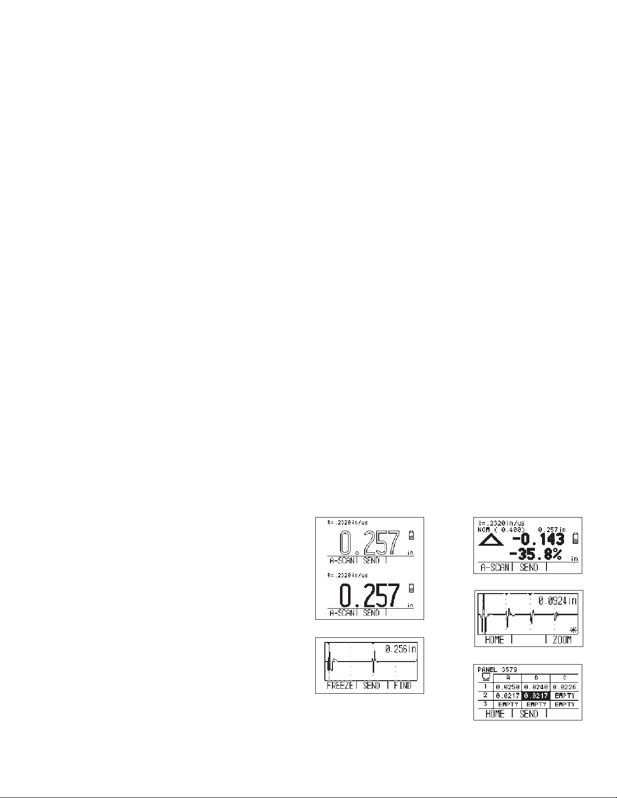
• Snapshot A-Scan on all models
• Hollow/Fill thickness digits showing coupling or non-coupling
status
• Visual LED alarm to alert user when measurements are
exceeding the user selectable limit values
• Customer parameter set-ups for special configurations and
quick instrument set-up
• Flexible power system via standard AA batteries or
rechargeable battery pack system (standard)
• Multi-language user interface
• Automatic ultrasonic performance (gain and gate controls)
• Wide variety of standard probes (sold separately)
Filled digits indicate successful coupling
Live A-Scan for more precise evaluations
Rate of reduction
Data recorder
Snapshot A-Scan
CL5––Simply reliable, reliably
simple
The Velocity Option: Performance and Flexibility
The CL5 Velocity option gives the user an added measurement
mode used for determining the velocity of a known thickness of
material. Material thickness can be entered manually via the CL5
keyboard or a digital caliper can be connected, allowing the
thickness value to be sent electronically from the caliper to the
CL5. The user simply places the probe on the part, and the CL5
displays the material velocity of the test object. Both the thickness
and the velocity value can be stored in the Data Recorder and
downloaded to the PC.
The Live A-Scan Option
The optional Live A-Scan feature gives the user a real time view of
the echoes being digitally measured by the CL5.
Viewing the Live A-Scan can aid users when attempting to
properly align the probe and the test object to achieve the best
measurement values. Viewing the Live A-Scan enables the user to
ensure the proper echoes are being measured and the digital
value is correct.
The Data Recorder Option
The Data Recorder option permits the quick and easy storage of
thickness values in file form. Fully user-programmable, it stores up
to 10,000 measured values or as many as 500 values with
attached A-Scan.
The programmable data recorder allows creation of data recorder
files directly from the CL5 keypad, or from the PC using the
flexible UltraMATE
®
or UltraMATE®Lite software program. The
Data Recorder supports the use of alphanumeric file names,
standard linear and grid files and custom linear files.
Extended file types store the thickness values, velocity settings
and other critical data for each measurement point, making the
CL5 and UltraMATE
®
ideal for test data management.
Page 3

Achieve More Precision With
Quality View
Quality View Mode permits Data Recorder-driven control and
capture of thickness measurements. It is ideal for singular parts
or structures with numerous measurement points that have
different target thicknesses and/or varying upper and lower limits
or tolerances.
Uses of Quality View Mode include:
1. Fast collection of thickness measurement data for statistical
analysis during variation control and quality assurance.
2. Digitally capturing thickness measurement data for quality
records and traceability.
3. Variation control of work in progress on the manufacturing or
workshop floor.
Quality View Mode displays the current measurement location
name, a bar graphic of the thickness measurement that shows
the lower specified limit value, the nominal/target value, the
upper specified limit and a numerical readout of the
measurement.
Selection of Quality View Mode displays
To work in Quality View Mode, custom four-point linear files are created in either Microsoft®Excel or UltraMate®software applications
on a PC and downloaded to the CL5 using the optional serial or USB cable. Measurements can also be uploaded into a PC for
processing and analysis using Microsoft
®
Excel, UltraMate®or a third party statistics and/or quality software application.
Quality View Mode Out of tolerance dialogue Measurement Review Mode
Numerical value of thickness is filled when
probe is coupled to the location of measurement
Page 4

Model Probe Type Nominal Frequency Contact Diameter Measuring Range (in Mild Steel Unless Noted)
Alpha 2 DFR/CLF4 Standard Delay Line 15 MHz 0.30 in (7.6 mm) 0.007 to 1.0 in (0.18 to 25.4 mm)
Alpha 2 F/CLF5 Fingertip Contact 10 MHz 0.38 in (9.5 mm) 0.060 to 10.0 in (1.52 to 254 mm)
Mini DFR Thin Range Delay Line 20 MHz 0.19 in (4.8 mm) 0.006 to 0.2 in (0.16 to 5.1 mm)
Alpha DFR-P Delay Line for Plastic Materials 22 MHz 0.30 in (7.6 mm) 0.005 to 0.15 in (0.13 to 3.8 mm) in plastic materials
K-Pen Delay Line Pencil Probe 20 MHz 0.065 or 0.090 in (1.7 or 2.3 mm) 0.008 to 0.175 in (0.20 to 4.4 mm)
CA211A Standard Contact 5 MHz 0.75 in (19.1 mm) 0.060 to 20.0 in (1.52 to 508 mm)
g
GE Inspection Technologies: productivity through inspection solutions
GE Inspection Technologies provides technology-driven inspection solutions that deliver productivity, quality and safety. We design,
manufacture and service ultrasonic, remote visual, radiographic and eddy current equipment and systems. We offer
specialized solutions that will help you improve productivity in your applications in the aerospace, power generation, oil & gas,
automotive or metals Industries.
www.ge.com/inspectiontechnologies
© 2007 General Electric Company. All Rights Reserved. We reserve the right to technical modifications without prior notice. GE®is a registered trademark of General Electric Co. Other company or product names
mentioned in this document may be trademarks or registered trademarks of their respective companies, which are not affiliated with GE.
GEIT-20206EN (09/07)
CL5 Compatible Transducer Specifications
Environmental Sealing Impact resistant, dust and splash proof, gasket-
sealed, case-tested to IP54
Weight 0.92 lb (420 g) with batteries
Size 7.1 in H × 3.7 in W × 1.8 in D
(180 mm × 94 mm × 46 mm)
Temperature Range Operating: –10 ºC to +60 ºC
Storage: –20 ºC to +70 ºC
Operating Languages English, German, French, Spanish, Italian, Russian,
Japanese, Chinese
Application Software UltraMATE®Lite and UltraMATE
®
Base Instrument Package CL5 precision thickness gauge
Lithium poly battery pack
AC power supply
Plastic carry case
Wire stand
XL couplant sample, 4 oz
Firmware upgrade CD-ROM
Operating manual
Operating instruction card
Certificate of Conformity
Options CL5 AS OPT – Live A-Scan option
CL5 DR OPT – Data Recorder option
CL5 VL – Velocity option
Accessories PCCBL-690 USB PC cable
PCCBL-419 serial PC cable
Li-135 lithium poly battery pack
AC-296 AC power supply
UltraMATE
®
Lite or UltraMATE
®
Data Management software
Measuring Range .005 in to 20.00 in (0.13 mm to 500 mm): depends
on material, probe, surface condition and
temperature
Units and Measuring Resolution Inch – 0.0001, 0.001, 0.01 Millimeter – 0.001, 0.01, 0.1
Material Velocity Range 0.03937 to 0.78736 in/μs 1000 to 19999 m/s
Receiver Bandwidth of 1.0 to 16 MHz at –6 dB
Update Rate User selectable 4 or 8 Hz, up to 32 Hz in Min Cap or
Max Cap mode
Display Type Graphical LCD 64 × 128 pixels
2.25 in × 2.56 in (40 mm × 57 mm) with backlight
and adjustable contrast
Thickness Display Five-digit display with 0.75 in (19.5 mm) height digits
in standard mode and 0.25 in (6.35 mm) height digits
in Thickness + A-Scan mode, solid or hollow digits
coupling indicator, A-Scan view – R.F. mode only
Display Modes Thickness (includes Snapshot A-Scan), Thickness +
Live A-Scan (optional), Minimum Capture, Maximum
Capture, Differential and Rate of Reduction, Velocity
Mode (optional), Quality View Mode (optional)
Supervisor Lockout Alphanumeric password lockout for calibrations,
set-up and Data Recorder
I/O Port Bi-directional serial RS-232: baud rate 1200, 9600,
57600 and 115200
Data Recorder Programmable Data Recorder, 120 files max. on
each 64 MB SD card
File Formats Grid created from instrument keypad. Grid and
Custom Linear files accepted from UltraMATE
®
software.
Power Supply Three AA batteries (Alkaline, NiMH or NiCad) or
custom rechargeable battery pack
Technical Data
 Loading...