

Page 1

CIC ProTM and Unity Network
Information Suite (IS) Server
Service Manual
2001099-019 Revision F
®
g
GE Medical Systems
Information Technologies
gemedicalsystem.com
Page 2

127(
Due to continuing product innovation, specifications in this manual are subject
to change without notice.
Listed below are GE Medical Systems Information Technologies trademarks used in this manual. All other trademarks
contained herein are the property of their respective owners.
UNITY NETWORK, ApexPro, CD TELEMETRY, and RSVP are trademarks of GE Medical Systems Information
Technologies registered in the United States Patent and Trademark Office.
CD TELEMETRY
®
–LAN, CENTRALSCOPE, CIC Pro, ICMMS, Prism, Octacomm, and Octanet are trademarks of GE
Medical Systems Information Technologies.
© GE Medical Systems Information Tech nologies, 2001, 2002, 2003. All rights reserved.
T-2 CIC Pro and Unity Network IS Server Revision F
2001099-019 21 February 2003
Page 3

Contents
1 Introduction . . . . . . . . . . . . . . . . . . . . . . . . . . . . . . . . . . . . 1-1
License Agreement . . . . . . . . . . . . . . . . . . . . . . . . . . . . . . . . . . . . . . . . . . . . . . . . . . 1-3
Manual Information . . . . . . . . . . . . . . . . . . . . . . . . . . . . . . . . . . . . . . . . . . . . . . . . . . 1-6
Revision History . . . . . . . . . . . . . . . . . . . . . . . . . . . . . . . . . . . . . . . . . . . . . . . . . . .1-6
Purpose of Manual . . . . . . . . . . . . . . . . . . . . . . . . . . . . . . . . . . . . . . . . . . . . . . . . .1-6
Scope of Manual . . . . . . . . . . . . . . . . . . . . . . . . . . . . . . . . . . . . . . . . . . . . . . . . . .1-7
Safety Information . . . . . . . . . . . . . . . . . . . . . . . . . . . . . . . . . . . . . . . . . . . . . . . . . . . 1-9
Responsibility of the Manufacturer . . . . . . . . . . . . . . . . . . . . . . . . . . . . . . . . . . . . .1-9
Intended Use . . . . . . . . . . . . . . . . . . . . . . . . . . . . . . . . . . . . . . . . . . . . . . . . . . . . .1-9
Warnings, Cautions, and Notes . . . . . . . . . . . . . . . . . . . . . . . . . . . . . . . . . . . . . .1-12
Equipment Symbols . . . . . . . . . . . . . . . . . . . . . . . . . . . . . . . . . . . . . . . . . . . . . . . . 1-13
Service Information . . . . . . . . . . . . . . . . . . . . . . . . . . . . . . . . . . . . . . . . . . . . . . . . . 1-14
Service Requirements . . . . . . . . . . . . . . . . . . . . . . . . . . . . . . . . . . . . . . . . . . . . .1-14
Equipment Identification . . . . . . . . . . . . . . . . . . . . . . . . . . . . . . . . . . . . . . . . . . . .1-14
Warranty . . . . . . . . . . . . . . . . . . . . . . . . . . . . . . . . . . . . . . . . . . . . . . . . . . . . . . .1-14
2 Equipment Description . . . . . . . . . . . . . . . . . . . . . . . . . . . 2-1
General System Information . . . . . . . . . . . . . . . . . . . . . . . . . . . . . . . . . . . . . . . . . . . 2-3
Network Information . . . . . . . . . . . . . . . . . . . . . . . . . . . . . . . . . . . . . . . . . . . . . . . .2-3
Un-Interruptible Power Supplies . . . . . . . . . . . . . . . . . . . . . . . . . . . . . . . . . . . . . .2-4
How Trends are Calculated . . . . . . . . . . . . . . . . . . . . . . . . . . . . . . . . . . . . . . . . . .2-6
Time and Date Configuration . . . . . . . . . . . . . . . . . . . . . . . . . . . . . . . . . . . . . . . . .2-6
Safe Shutdown Procedure . . . . . . . . . . . . . . . . . . . . . . . . . . . . . . . . . . . . . . . . . . .2-7
CIC Pro and ApexPro System Components . . . . . . . . . . . . . . . . . . . . . . . . . . . . . . 2-8
Hardware . . . . . . . . . . . . . . . . . . . . . . . . . . . . . . . . . . . . . . . . . . . . . . . . . . . . . . . .2-8
ApexPro Telemetry System . . . . . . . . . . . . . . . . . . . . . . . . . . . . . . . . . . . . . . . . . .2-8
CIC Pro and ApexPro Functional Description . . . . . . . . . . . . . . . . . . . . . . . . . . . . . 2-9
CIC Pro . . . . . . . . . . . . . . . . . . . . . . . . . . . . . . . . . . . . . . . . . . . . . . . . . . . . . . . . .2-9
ApexPro Telemetry System . . . . . . . . . . . . . . . . . . . . . . . . . . . . . . . . . . . . . . . . . .2-9
Printed Output . . . . . . . . . . . . . . . . . . . . . . . . . . . . . . . . . . . . . . . . . . . . . . . . . . . .2-9
Administrative and Service Access . . . . . . . . . . . . . . . . . . . . . . . . . . . . . . . . . . .2-10
Logs . . . . . . . . . . . . . . . . . . . . . . . . . . . . . . . . . . . . . . . . . . . . . . . . . . . . . . . . . . .2-10
CIC Pro Service Logons . . . . . . . . . . . . . . . . . . . . . . . . . . . . . . . . . . . . . . . . . . . . . 2-11
General . . . . . . . . . . . . . . . . . . . . . . . . . . . . . . . . . . . . . . . . . . . . . . . . . . . . . . . .2-11
Full-Access Logons . . . . . . . . . . . . . . . . . . . . . . . . . . . . . . . . . . . . . . . . . . . . . . .2-11
Limited-Access Logon . . . . . . . . . . . . . . . . . . . . . . . . . . . . . . . . . . . . . . . . . . . . .2-12
Run-Time Logon . . . . . . . . . . . . . . . . . . . . . . . . . . . . . . . . . . . . . . . . . . . . . . . . .2-12
Revision F CIC Pro and Unity Network IS Server i
2001099-019
Page 4

CIC Pro IP Address Information . . . . . . . . . . . . . . . . . . . . . . . . . . . . . . . . . . . . . . . 2-13
Display All IP Addresses . . . . . . . . . . . . . . . . . . . . . . . . . . . . . . . . . . . . . . . . . . .2-13
Change the Unity Network MC IP Address . . . . . . . . . . . . . . . . . . . . . . . . . . . . .2-14
Change the Unity Network IX IP Address . . . . . . . . . . . . . . . . . . . . . . . . . . . . . .2-15
CIC Pro Setup Utility . . . . . . . . . . . . . . . . . . . . . . . . . . . . . . . . . . . . . . . . . . . . . . . . 2-16
CIC Pro Telemetry Tower Option . . . . . . . . . . . . . . . . . . . . . . . . . . . . . . . . . . . . . . 2-17
CIC Pro Full Disclosure License Management Setup . . . . . . . . . . . . . . . . . . . . . 2-19
BCM Server . . . . . . . . . . . . . . . . . . . . . . . . . . . . . . . . . . . . . . . . . . . . . . . . . . . . .2-19
Nightshade Server Without Full Disclosure . . . . . . . . . . . . . . . . . . . . . . . . . . . . .2-19
ApexPro PTSCONFIG Utility . . . . . . . . . . . . . . . . . . . . . . . . . . . . . . . . . . . . . . . . . . 2-20
display Commands . . . . . . . . . . . . . . . . . . . . . . . . . . . . . . . . . . . . . . . . . . . . . . .2-20
modify Command . . . . . . . . . . . . . . . . . . . . . . . . . . . . . . . . . . . . . . . . . . . . . . . . .2-21
listwhat Command . . . . . . . . . . . . . . . . . . . . . . . . . . . . . . . . . . . . . . . . . . . . . . . .2-21
Other Commands . . . . . . . . . . . . . . . . . . . . . . . . . . . . . . . . . . . . . . . . . . . . . . . . .2-22
Unity Network IS System Components . . . . . . . . . . . . . . . . . . . . . . . . . . . . . . . . . 2-23
Hardware . . . . . . . . . . . . . . . . . . . . . . . . . . . . . . . . . . . . . . . . . . . . . . . . . . . . . . .2-23
RSVP System . . . . . . . . . . . . . . . . . . . . . . . . . . . . . . . . . . . . . . . . . . . . . . . . . . .2-23
Unity Network IS Functional Description . . . . . . . . . . . . . . . . . . . . . . . . . . . . . . . 2-24
RSVP Option . . . . . . . . . . . . . . . . . . . . . . . . . . . . . . . . . . . . . . . . . . . . . . . . . . . .2-24
Auto View Option . . . . . . . . . . . . . . . . . . . . . . . . . . . . . . . . . . . . . . . . . . . . . . . . .2-25
HL7 Outbound Option . . . . . . . . . . . . . . . . . . . . . . . . . . . . . . . . . . . . . . . . . . . . .2-26
ICMMS Option . . . . . . . . . . . . . . . . . . . . . . . . . . . . . . . . . . . . . . . . . . . . . . . . . . .2-26
Service Web Option . . . . . . . . . . . . . . . . . . . . . . . . . . . . . . . . . . . . . . . . . . . . . . .2-27
Logs . . . . . . . . . . . . . . . . . . . . . . . . . . . . . . . . . . . . . . . . . . . . . . . . . . . . . . . . . . .2-27
Unity Network IS Service Logon . . . . . . . . . . . . . . . . . . . . . . . . . . . . . . . . . . . . . . 2-28
Unity Network IS Configuration Utility . . . . . . . . . . . . . . . . . . . . . . . . . . . . . . . . . . 2-29
Control Functions . . . . . . . . . . . . . . . . . . . . . . . . . . . . . . . . . . . . . . . . . . . . . . . . .2-29
Number of Instances Running . . . . . . . . . . . . . . . . . . . . . . . . . . . . . . . . . . . . . . .2-29
RSVP Port Status (Version 4.2 and Earlier) . . . . . . . . . . . . . . . . . . . . . . . . . . . .2-31
Unity Network IS Port Server Firmware . . . . . . . . . . . . . . . . . . . . . . . . . . . . . . . . . 2-32
3 CIC Pro/ApexPro Installation & Configuration . . . . . . . . 3-1
Pre-Installation Requirements . . . . . . . . . . . . . . . . . . . . . . . . . . . . . . . . . . . . . . . . . 3-3
Site Requirements . . . . . . . . . . . . . . . . . . . . . . . . . . . . . . . . . . . . . . . . . . . . . . . . .3-3
Power Requirements . . . . . . . . . . . . . . . . . . . . . . . . . . . . . . . . . . . . . . . . . . . . . . .3-5
Equipment Grounding . . . . . . . . . . . . . . . . . . . . . . . . . . . . . . . . . . . . . . . . . . . . . .3-6
CIC Pro Installation . . . . . . . . . . . . . . . . . . . . . . . . . . . . . . . . . . . . . . . . . . . . . . . . . . 3-7
Pre-Installation Check . . . . . . . . . . . . . . . . . . . . . . . . . . . . . . . . . . . . . . . . . . . . . .3-8
Connect Keyboard and Mouse . . . . . . . . . . . . . . . . . . . . . . . . . . . . . . . . . . . . . . .3-8
Install the Speakers . . . . . . . . . . . . . . . . . . . . . . . . . . . . . . . . . . . . . . . . . . . . . . . .3-9
Install the Power Cord . . . . . . . . . . . . . . . . . . . . . . . . . . . . . . . . . . . . . . . . . . . . .3-10
Connect the Video Display Monitor . . . . . . . . . . . . . . . . . . . . . . . . . . . . . . . . . . .3-10
Connect the Digital Writer Printer . . . . . . . . . . . . . . . . . . . . . . . . . . . . . . . . . . . .3-11
ii CIC Pro and Unity Network IS Server Revision F
2001099-019
Page 5

ApexPro Option Installation . . . . . . . . . . . . . . . . . . . . . . . . . . . . . . . . . . . . . . . . . . 3-11
CIC Pro Configuration . . . . . . . . . . . . . . . . . . . . . . . . . . . . . . . . . . . . . . . . . . . . . . . 3-12
Logon . . . . . . . . . . . . . . . . . . . . . . . . . . . . . . . . . . . . . . . . . . . . . . . . . . . . . . . . . .3-12
Configure Time/Date Settings . . . . . . . . . . . . . . . . . . . . . . . . . . . . . . . . . . . . . . .3-12
Connect to Unity Network . . . . . . . . . . . . . . . . . . . . . . . . . . . . . . . . . . . . . . . . . .3-15
Install Optional Licenses . . . . . . . . . . . . . . . . . . . . . . . . . . . . . . . . . . . . . . . . . . .3-15
Install Printer . . . . . . . . . . . . . . . . . . . . . . . . . . . . . . . . . . . . . . . . . . . . . . . . . . . .3-16
Setup the CIC Pro . . . . . . . . . . . . . . . . . . . . . . . . . . . . . . . . . . . . . . . . . . . . . . . .3-19
Lock or Unlock Beds . . . . . . . . . . . . . . . . . . . . . . . . . . . . . . . . . . . . . . . . . . . . . .3-36
ApexPro Configuration . . . . . . . . . . . . . . . . . . . . . . . . . . . . . . . . . . . . . . . . . . . . . . 3-37
Browser Configuration . . . . . . . . . . . . . . . . . . . . . . . . . . . . . . . . . . . . . . . . . . . . . . 3-39
Completion . . . . . . . . . . . . . . . . . . . . . . . . . . . . . . . . . . . . . . . . . . . . . . . . . . . . . . . . 3-41
4 Unity Network IS Installation & Configuration . . . . . . . . 4-1
Pre-Installation Requirements . . . . . . . . . . . . . . . . . . . . . . . . . . . . . . . . . . . . . . . . . 4-3
Site Requirements . . . . . . . . . . . . . . . . . . . . . . . . . . . . . . . . . . . . . . . . . . . . . . . . .4-3
Power Requirements . . . . . . . . . . . . . . . . . . . . . . . . . . . . . . . . . . . . . . . . . . . . . . .4-5
Equipment Grounding . . . . . . . . . . . . . . . . . . . . . . . . . . . . . . . . . . . . . . . . . . . . . .4-6
Unity Network IS Installation . . . . . . . . . . . . . . . . . . . . . . . . . . . . . . . . . . . . . . . . . . 4-7
Pre-Installation Check . . . . . . . . . . . . . . . . . . . . . . . . . . . . . . . . . . . . . . . . . . . . . .4-7
Connect Keyboard and Mouse . . . . . . . . . . . . . . . . . . . . . . . . . . . . . . . . . . . . . . .4-8
Install the Power Cord . . . . . . . . . . . . . . . . . . . . . . . . . . . . . . . . . . . . . . . . . . . . . .4-8
Connect the Video Display Monitor . . . . . . . . . . . . . . . . . . . . . . . . . . . . . . . . . . . .4-9
Unity Network IS Configuration . . . . . . . . . . . . . . . . . . . . . . . . . . . . . . . . . . . . . . . 4-10
Logon . . . . . . . . . . . . . . . . . . . . . . . . . . . . . . . . . . . . . . . . . . . . . . . . . . . . . . . . . .4-10
Configure Time/Date Settings . . . . . . . . . . . . . . . . . . . . . . . . . . . . . . . . . . . . . . .4-10
Connect to Unity Network . . . . . . . . . . . . . . . . . . . . . . . . . . . . . . . . . . . . . . . . . .4-12
Install Optional Licenses . . . . . . . . . . . . . . . . . . . . . . . . . . . . . . . . . . . . . . . . . . .4-13
Setup the Unity Network IS Server . . . . . . . . . . . . . . . . . . . . . . . . . . . . . . . . . . .4-14
Completion . . . . . . . . . . . . . . . . . . . . . . . . . . . . . . . . . . . . . . . . . . . . . . . . . . . . . . . . 4-28
Restarting the Computer . . . . . . . . . . . . . . . . . . . . . . . . . . . . . . . . . . . . . . . . . . .4-28
Restarting the Application . . . . . . . . . . . . . . . . . . . . . . . . . . . . . . . . . . . . . . . . . .4-28
Checkout Procedure . . . . . . . . . . . . . . . . . . . . . . . . . . . . . . . . . . . . . . . . . . . . . .4-28
5 Maintenance . . . . . . . . . . . . . . . . . . . . . . . . . . . . . . . . . . . 5-1
Schedule . . . . . . . . . . . . . . . . . . . . . . . . . . . . . . . . . . . . . . . . . . . . . . . . . . . . . . . . . . . 5-3
Manufacturer Recommendation . . . . . . . . . . . . . . . . . . . . . . . . . . . . . . . . . . . . . . .5-3
PM Form . . . . . . . . . . . . . . . . . . . . . . . . . . . . . . . . . . . . . . . . . . . . . . . . . . . . . . . .5-3
Visual Inspection . . . . . . . . . . . . . . . . . . . . . . . . . . . . . . . . . . . . . . . . . . . . . . . . . . . . 5-4
About the Visual Inspection . . . . . . . . . . . . . . . . . . . . . . . . . . . . . . . . . . . . . . . . . .5-4
Procedure . . . . . . . . . . . . . . . . . . . . . . . . . . . . . . . . . . . . . . . . . . . . . . . . . . . . . . .5-4
Revision F CIC Pro and Unity Network IS Server iii
2001099-019
Page 6

Cleaning . . . . . . . . . . . . . . . . . . . . . . . . . . . . . . . . . . . . . . . . . . . . . . . . . . . . . . . . . . . 5-5
General Rules . . . . . . . . . . . . . . . . . . . . . . . . . . . . . . . . . . . . . . . . . . . . . . . . . . . .5-5
Cleaning Procedure . . . . . . . . . . . . . . . . . . . . . . . . . . . . . . . . . . . . . . . . . . . . . . . .5-5
Display Screen . . . . . . . . . . . . . . . . . . . . . . . . . . . . . . . . . . . . . . . . . . . . . . . . . . . .5-6
Hard Drive Replacement . . . . . . . . . . . . . . . . . . . . . . . . . . . . . . . . . . . . . . . . . . . . . . 5-7
Record Configuration Information (CIC Pro) . . . . . . . . . . . . . . . . . . . . . . . . . . . . .5-7
Record Configuration Information (Unity Network IS) . . . . . . . . . . . . . . . . . . . . .5-11
Preparation . . . . . . . . . . . . . . . . . . . . . . . . . . . . . . . . . . . . . . . . . . . . . . . . . . . . .5-12
Remove and Install Hard Drive (Nightshade Server) . . . . . . . . . . . . . . . . . . . . . .5-12
Remove and Install Hard Drive (BCM Server) . . . . . . . . . . . . . . . . . . . . . . . . . . .5-14
Install Gold Drive Image . . . . . . . . . . . . . . . . . . . . . . . . . . . . . . . . . . . . . . . . . . . .5-17
Configure Gold Drive to Product Drive (G2P) . . . . . . . . . . . . . . . . . . . . . . . . . . .5-17
Electrical Safety Tests . . . . . . . . . . . . . . . . . . . . . . . . . . . . . . . . . . . . . . . . . . . . . . . 5-23
General . . . . . . . . . . . . . . . . . . . . . . . . . . . . . . . . . . . . . . . . . . . . . . . . . . . . . . . .5-23
Recommendations . . . . . . . . . . . . . . . . . . . . . . . . . . . . . . . . . . . . . . . . . . . . . . . .5-23
Wall Receptacle Test . . . . . . . . . . . . . . . . . . . . . . . . . . . . . . . . . . . . . . . . . . . . . .5-24
Ground (Earth) Integrity . . . . . . . . . . . . . . . . . . . . . . . . . . . . . . . . . . . . . . . . . . . .5-24
Ground (Earth) Wire Leakage Current Tests . . . . . . . . . . . . . . . . . . . . . . . . . . . .5-26
Enclosure (Chassis) Leakage Current Test . . . . . . . . . . . . . . . . . . . . . . . . . . . . .5-27
Test Completion . . . . . . . . . . . . . . . . . . . . . . . . . . . . . . . . . . . . . . . . . . . . . . . . . .5-28
Checkout Procedure . . . . . . . . . . . . . . . . . . . . . . . . . . . . . . . . . . . . . . . . . . . . . . . . 5-29
About the checkout procedure . . . . . . . . . . . . . . . . . . . . . . . . . . . . . . . . . . . . . . .5-29
Instructions . . . . . . . . . . . . . . . . . . . . . . . . . . . . . . . . . . . . . . . . . . . . . . . . . . . . . .5-29
Repair Log . . . . . . . . . . . . . . . . . . . . . . . . . . . . . . . . . . . . . . . . . . . . . . . . . . . . . . . . 5-36
6 Troubleshooting . . . . . . . . . . . . . . . . . . . . . . . . . . . . . . . . 6-1
Hardware General . . . . . . . . . . . . . . . . . . . . . . . . . . . . . . . . . . . . . . . . . . . . . . . . . . . 6-3
Blank Display, Unit Doesn’t Boot . . . . . . . . . . . . . . . . . . . . . . . . . . . . . . . . . . . . . .6-3
Troubleshooting the Components . . . . . . . . . . . . . . . . . . . . . . . . . . . . . . . . . . . . .6-3
Controlling Electrostatic Discharge Damage . . . . . . . . . . . . . . . . . . . . . . . . . . . . .6-3
Accessing Service Utilities . . . . . . . . . . . . . . . . . . . . . . . . . . . . . . . . . . . . . . . . . . . . 6-5
Command Prompt . . . . . . . . . . . . . . . . . . . . . . . . . . . . . . . . . . . . . . . . . . . . . . . . .6-5
CIC Pro Log Files . . . . . . . . . . . . . . . . . . . . . . . . . . . . . . . . . . . . . . . . . . . . . . . . . .6-5
Troubleshooting a CIC Pro Server Tower . . . . . . . . . . . . . . . . . . . . . . . . . . . . . . . . 6-7
Intel Server Control (ISC–Nightshade Box Only) . . . . . . . . . . . . . . . . . . . . . . . . . .6-7
DMI Error Message (Nightshade Box Only) . . . . . . . . . . . . . . . . . . . . . . . . . . . . . . 6-9
Canceling CIC Pro Print Jobs . . . . . . . . . . . . . . . . . . . . . . . . . . . . . . . . . . . . . . . . . 6-13
iv CIC Pro and Unity Network IS Server Revision F
2001099-019
Page 7

Capture All Logs on the CIC Pro . . . . . . . . . . . . . . . . . . . . . . . . . . . . . . . . . . . . . . 6-14
Use the Get All Logs Tool . . . . . . . . . . . . . . . . . . . . . . . . . . . . . . . . . . . . . . . . . .6-14
FileSplit . . . . . . . . . . . . . . . . . . . . . . . . . . . . . . . . . . . . . . . . . . . . . . . . . . . . . . . .6-18
Duplicate TTX . . . . . . . . . . . . . . . . . . . . . . . . . . . . . . . . . . . . . . . . . . . . . . . . . . .6-19
List Network . . . . . . . . . . . . . . . . . . . . . . . . . . . . . . . . . . . . . . . . . . . . . . . . . . . . .6-20
Open RTERM Session . . . . . . . . . . . . . . . . . . . . . . . . . . . . . . . . . . . . . . . . . . . . .6-21
Copying CDT LAN Telemetry Logs From CIC Pro . . . . . . . . . . . . . . . . . . . . . . .6-22
ApexPro Application Log Files . . . . . . . . . . . . . . . . . . . . . . . . . . . . . . . . . . . . . . . . 6-23
File Handling . . . . . . . . . . . . . . . . . . . . . . . . . . . . . . . . . . . . . . . . . . . . . . . . . . . . . . 6-24
General . . . . . . . . . . . . . . . . . . . . . . . . . . . . . . . . . . . . . . . . . . . . . . . . . . . . . . . .6-24
Towers, ApexPro and CIC Pro . . . . . . . . . . . . . . . . . . . . . . . . . . . . . . . . . . . . . . .6-24
Admit/TTX Master . . . . . . . . . . . . . . . . . . . . . . . . . . . . . . . . . . . . . . . . . . . . . . . .6-25
Telemetry Towers, Receivers, and Unit Names . . . . . . . . . . . . . . . . . . . . . . . . .6-26
Full Disclosure . . . . . . . . . . . . . . . . . . . . . . . . . . . . . . . . . . . . . . . . . . . . . . . . . . .6-29
Troubleshooting the ApexPro System . . . . . . . . . . . . . . . . . . . . . . . . . . . . . . . . . . 6-35
Unity Network IS Event and Error Logs . . . . . . . . . . . . . . . . . . . . . . . . . . . . . . . . . 6-37
Log Registry Settings (Version 4.3 and Later) . . . . . . . . . . . . . . . . . . . . . . . . . . .6-37
HL7 Registry Settings (Version 4.1 and Later) . . . . . . . . . . . . . . . . . . . . . . . . . . . 6-38
HL7 Communication Troubleshooting . . . . . . . . . . . . . . . . . . . . . . . . . . . . . . . . . . 6-46
7 Assembly Drawings . . . . . . . . . . . . . . . . . . . . . . . . . . . . . 7-1
General . . . . . . . . . . . . . . . . . . . . . . . . . . . . . . . . . . . . . . . . . . . . . . . . . . . . . . . . . . . . 7-3
Back Panel Connections . . . . . . . . . . . . . . . . . . . . . . . . . . . . . . . . . . . . . . . . . . . . . . 7-4
CIC Pro Nightshade Server . . . . . . . . . . . . . . . . . . . . . . . . . . . . . . . . . . . . . . . . . .7-4
CIC Pro BCM Server . . . . . . . . . . . . . . . . . . . . . . . . . . . . . . . . . . . . . . . . . . . . . . .7-5
Unity Network IS Nightshade Server . . . . . . . . . . . . . . . . . . . . . . . . . . . . . . . . . . .7-6
Unity Network IS BCM Server . . . . . . . . . . . . . . . . . . . . . . . . . . . . . . . . . . . . . . . .7-7
Server Tower . . . . . . . . . . . . . . . . . . . . . . . . . . . . . . . . . . . . . . . . . . . . . . . . . . . . . . . 7-8
Nightshade Server . . . . . . . . . . . . . . . . . . . . . . . . . . . . . . . . . . . . . . . . . . . . . . . . .7-8
BCM Server . . . . . . . . . . . . . . . . . . . . . . . . . . . . . . . . . . . . . . . . . . . . . . . . . . . . . .7-9
CIC Pro System Block Diagrams . . . . . . . . . . . . . . . . . . . . . . . . . . . . . . . . . . . . . . 7-10
Nightshade Server . . . . . . . . . . . . . . . . . . . . . . . . . . . . . . . . . . . . . . . . . . . . . . . .7-10
BCM Server . . . . . . . . . . . . . . . . . . . . . . . . . . . . . . . . . . . . . . . . . . . . . . . . . . . . .7-11
CIC Pro Parts Lists . . . . . . . . . . . . . . . . . . . . . . . . . . . . . . . . . . . . . . . . . . . . . . . . . 7-12
CIC Nightshade Server . . . . . . . . . . . . . . . . . . . . . . . . . . . . . . . . . . . . . . . . . . . .7-12
CIC BCM Server . . . . . . . . . . . . . . . . . . . . . . . . . . . . . . . . . . . . . . . . . . . . . . . . .7-13
CIC Keyboard Kit Table . . . . . . . . . . . . . . . . . . . . . . . . . . . . . . . . . . . . . . . . . . . .7-15
Unity Network IS System Block Diagrams . . . . . . . . . . . . . . . . . . . . . . . . . . . . . . 7-16
Nightshade Server Basic (Software Version 3.0) . . . . . . . . . . . . . . . . . . . . . . . . .7-16
BCM Server Basic (Software Version 4.1, 4.2, and 4.3) . . . . . . . . . . . . . . . . . . .7-17
Nightshade Server with RSVP (Software Version 3.0) . . . . . . . . . . . . . . . . . . . .7-18
BCM Server with RSVP (Software Version 4.1 and 4.2) . . . . . . . . . . . . . . . . . . .7-19
Revision F CIC Pro and Unity Network IS Server v
2001099-019
Page 8

Unity Network IS Parts Lists . . . . . . . . . . . . . . . . . . . . . . . . . . . . . . . . . . . . . . . . . . 7-20
Unity Network IS Assembly Nightshade Server (V3.0) . . . . . . . . . . . . . . . . . . . .7-20
Unity Network IS Assembly BCM Server—PN 2008540-001 . . . . . . . . . . . . . . .7-21
Unity Network IS Assembly BCM Server—PN 2008540-002 . . . . . . . . . . . . . . .7-26
Unity Network IS Keyboards . . . . . . . . . . . . . . . . . . . . . . . . . . . . . . . . . . . . . . . .7-27
PC Motherboard Settings . . . . . . . . . . . . . . . . . . . . . . . . . . . . . . . . . . . . . . . . . . . . 7-28
Nightshade Server Motherboard Jumper Settings . . . . . . . . . . . . . . . . . . . . . . . .7-28
CIC BCM Server Motherboard Switch Settings . . . . . . . . . . . . . . . . . . . . . . . . . .7-29
Unity Network IS BCM Server Motherboard Switch Settings . . . . . . . . . . . . . . . .7-32
Appendix A – Technical Specifications . . . . . . . . . . . . . .A-1
Technical Specifications–CIC Pro . . . . . . . . . . . . . . . . . . . . . . . . . . . . . . . . . . . . . . A-3
Performance Specifications (PC) . . . . . . . . . . . . . . . . . . . . . . . . . . . . . . . . . . . . . .A-3
Recorder (optional) . . . . . . . . . . . . . . . . . . . . . . . . . . . . . . . . . . . . . . . . . . . . . . . .A-3
General . . . . . . . . . . . . . . . . . . . . . . . . . . . . . . . . . . . . . . . . . . . . . . . . . . . . . . . . .A-4
Environmental Specifications (PC) . . . . . . . . . . . . . . . . . . . . . . . . . . . . . . . . . . . .A-4
Physical Specifications . . . . . . . . . . . . . . . . . . . . . . . . . . . . . . . . . . . . . . . . . . . . .A-5
Display Specifications . . . . . . . . . . . . . . . . . . . . . . . . . . . . . . . . . . . . . . . . . . . . . .A-5
Monitor (Display) Connections . . . . . . . . . . . . . . . . . . . . . . . . . . . . . . . . . . . . . . . .A-5
Certification . . . . . . . . . . . . . . . . . . . . . . . . . . . . . . . . . . . . . . . . . . . . . . . . . . . . . .A-5
Technical Specifications–Unity Network IS . . . . . . . . . . . . . . . . . . . . . . . . . . . . . . A-6
Performance Specifications (PC) . . . . . . . . . . . . . . . . . . . . . . . . . . . . . . . . . . . . . .A-6
General . . . . . . . . . . . . . . . . . . . . . . . . . . . . . . . . . . . . . . . . . . . . . . . . . . . . . . . . .A-6
Environmental Specifications (PC) . . . . . . . . . . . . . . . . . . . . . . . . . . . . . . . . . . . .A-7
Physical Specifications . . . . . . . . . . . . . . . . . . . . . . . . . . . . . . . . . . . . . . . . . . . . .A-7
Display Specifications . . . . . . . . . . . . . . . . . . . . . . . . . . . . . . . . . . . . . . . . . . . . . .A-7
Monitor (Display) Connections . . . . . . . . . . . . . . . . . . . . . . . . . . . . . . . . . . . . . . . .A-7
Certification . . . . . . . . . . . . . . . . . . . . . . . . . . . . . . . . . . . . . . . . . . . . . . . . . . . . . .A-7
Appendix B – Abbreviations and Symbols . . . . . . . . . . . .B-1
Abbreviations . . . . . . . . . . . . . . . . . . . . . . . . . . . . . . . . . . . . . . . . . . . . . . . . . . . . . . . B-3
Symbols . . . . . . . . . . . . . . . . . . . . . . . . . . . . . . . . . . . . . . . . . . . . . . . . . . . . . . . . . . . B-7
vi CIC Pro and Unity Network IS Server Revision F
2001099-019
Page 9

1 Introduction
Revision F CIC Pro and Unity Network IS Server 1-1
2001099-019
Page 10

For your notes
1-2 CIC Pro and Unity Network IS Server Revision F
2001099-019
Page 11

License Agreement
IT IS IMPORTANT THAT YOU CAREFULLY READ THE TERMS AND
CONDITIONS OF THIS LICENSE AGREEMENT BEFORE
COMMENCING THE USE OF THE CLINICAL INFORMATION
CENTER WORKSTATION (THE “WORKSTATION”) AND THE
CLINICAL INFORMATION CENTER PROGRAM RECORDED
THEREIN AND ANY ACCOMPANYING USER DOCUMENTATION
(“PROGRAM”). THIS LICENSE REPRESENTS THE ENTIRE
LICENSE AGREEMENT CONCERNING THE PROGRAM BETWEEN
YOU AND GE MEDICAL SYSTEMS INFORMATION
TECHNOLOGIES (“INFORMATION TECHNOLOGIES”) AND
SUPERSEDES ALL OTHER COMMUNICATIONS OR ADVERTISING
RELATED TO THE PROGRAM EXCEPT ANY TERMS AND
CONDITIONS OF SALE OR WARRANTIES OR WARRANTY
LIMITATIONS RELATIVE TO THE PROGRAM AND/OR THE
WORKSTATION AS MAY BE EMBODIED IN ANY
DOCUMENTATION SUPPLIED WITH THE WORKSTATION. BY
COMMENCING THE USE OF THE WORKSTATION AND THE
PROGRAM CONTAINED THEREIN, YOU ARE ACCEPTING AND
AGREEING TO BE BOUND BY ALL THE TERMS AND CONDITIONS
OF THIS LICENSE AGREEMENT. IF YOU ARE NOT WILLING TO BE
BOUND BY THE TERMS AND CONDITIONS OF THIS LICENSE
AGREEMENT, YOU SHOULD PROMPTLY RETURN THE
WORKSTATION TO GE Medical Systems Information Technologies
AND YOU WILL RECEIVE A REFUND OF THE PURCHASE PRICE.
Introduction: License Agreement
I. GRANT
The Program is capable of coupling o ne to sixt een pati ent monit oring
units to the Workstation. GE Medical Systems Information
Technologies hereby grants you a non-exclusive, non-transferable
right and license to use the Program for coupling the number of
patient monitoring units to the Workstation for which a per-unit
royalty has been paid pursuant to Article II hereof.
II. ROYALTY
You have paid GE Medical Systems Information Technologies a one-
time, per-unit royalty equal to GE Medical Systems Information
Technologies’ current published price fo r the use of the Program. T he
per-unit royalty is based on the actual number of patient monitors
intended to be coupled by the Program to the Workstation as stated
in the Purchase Order for the Workstation and the Program. If you
use the Program to couple any patient monitoring units to the
Workstation in addition to the number for which a per unit royalty
was previously paid, you agree to pay GE Medical Systems
Information Technologies an additional per-unit royalty equal to GE
Medical Systems Information Technologies’ then current published
royalty for the Program for each such additional patient monitoring
unit so coupled. The additional per-unit royalty shall be paid to GE
Medical Systems Information Technologies within 30 days of the use
of the Program to couple any such additional patient monitoring
units to the Workstation.
Revision F CIC Pro and Unity Network IS Server 1-3
2001099-019
Page 12

Introduction: License Agreement
III. LIMITATIONS
You hereby agree not to: (1) use the Program in any network or
system other than to couple patient monitoring units to the
Workstation; (2) make any copy of the Program for any reason, or
allow or assist others to do so; (3) modify, reverse engineer, de
compile or disassemble the Program or merge any part of the
Program into any other program; (4) rent, sell, sublease, assign,
transfer or otherwise share the Program or any of your rights in the
Program under this Agreement with any third party; or, (5) remove
or alter any copyright notice, labels or trademarks from the Program
or the Workstation .
IV. TITLE
This Licen se is not a sale. Title and a ll cop yrigh ts to the Pr ogram and
any copy made by you remains the sole property of GE Medical
Systems Information Technologies.
V. TERM
This Agreement shall continue in force until terminated. This
Agreement shall terminate automatically when you cease using the
Workstation and the Program for their intended purpose. GE
Medical Systems Information Technologies may terminate this
Agreement on 30 days written notice if you make any unauthorized
copies of the Program or fail to comply with any of the restrictions on
use of the Program as set forth herein.
VI. LIMITED WARRANTY, DISCLAIMER AND LIMITATION
OF LIABILITY
A. Licensor warrants that on the acceptance date the Program shall
be free from significant programming errors and shall operate and
conform to the published functional specifications applicable
thereto, and that the Program shall conform to the standards
generally observed in the industry for similar software.
B.This warranty shall be invalidated by your modification of the
Program if such modification or the interaction between such
modification and the Program as supplied by Information
Technologies is the cause of the defect, error or non-conformity.
C.Except as stated above, the warranty covering the Program and
the Workstation shall be either Information Technologies
Standard Warranty or Limited Extended Parts Warranty as
published by Information Technologies and hereby made a part
hereof.
D.EXCEPT FOR THE EXPRESS WARRANTIES STATED
HEREIN, GE Medical Systems Information Technologies
DISCLAIMS ALL WARRANTIES WITH REGARD TO THE
PROGRAM INCLUDING IMPLIED WARRANTIES OF
MERCHANTABILITY OR FITNESS FOR A PARTICULAR
PURPOSE.
1-4 CIC Pro and Unity Network IS Server Revision F
2001099-019
Page 13

Introduction: License Agreement
E. GE Medical Systems Information Technologies entire liability to
you arising out of or in connection with this Agreement shall not
exceed the per-unit royalty paid to GE Medical Systems
Information Technologies for use of the Program. You
acknowledge that the amount paid to Information Technologies for
use of the Program is insufficient for Information Technologies to
undertake any greater risk. IN NO EVENT SHALL
INFORMATION TECHNOLOGIES BE LIABLE FOR ANY
INDIRECT, INCIDENTAL, CONSEQUENTIAL, SPECIAL OR
EXEMPLARY DAMAGES (INCLUDING WITHOUT
LIMITATION, LOST PROFITS, BUSINESS INTERRUPTION,
LOSS OF BUSINESS INFORMATION, PERSONAL INJURY OR
ANY OTHER PECUNIARY LOSS) ARISING FROM THE USE
OF THE PROGRAM, EVEN IF INFORMATION
TECHNOLOGIES HAS BEEN ADVISED OF THE POSSIBILITY
OF SUCH DAMAGES.
VII. GOVERNING LAW
This Agreement shall be governed by the laws of the State of
Wisconsin.
VIII.PARTIAL INVALIDITY
If any provision of this Agreement is held invalid or unenforceable,
the remaining portions of the Agreement shall continue in full force
and effect.
Revision F CIC Pro and Unity Network IS Server 1-5
2001099-019
Page 14
Manual Informatio n
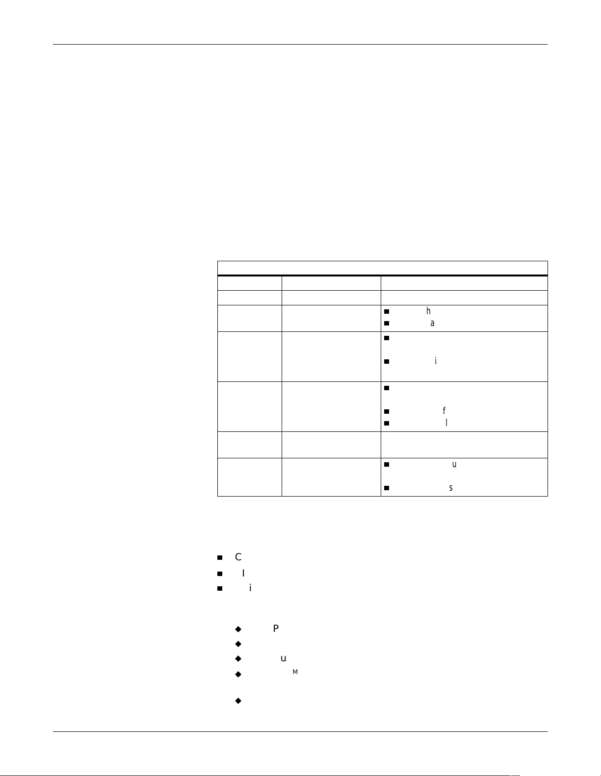
Revision History
Each page of this manual has a revision letter located at the bottom of
the page. It identifies the revi sion level of the enti re manual. This may be
important if you have more than one manual and you wish to know
which is the most current.
For the initial rel ease, all pages have the revision letter A. For the
second update, all pages receive the revision letter B. The latest letter of
the alphabet added to the table below corresponds to the most current
revision
Introduction: Manual Information
Table 1. Revision History
Revision Date Comment
A 22 January 2001 Initial Release
B 18 September 2001
C 18 December 2001
n
Add new hardware platform information.
n
General manual updates.
n
Revise BOM for Unity Network IS BCM
box.
n
Add hard drive replacement for Unity
Network IS.
D 5 June 2002
n
Revise Unity Network IS HL7 Registry
Settings.
n
Added set-up for CIC mirroring.
n
Updated parts list for BCM Servers
E 26 August 2002 Added support for enhanced Full Disclosure
features.
F 21 February 2003
n
General manual updates to support CIC
and Unity Network IS software upgrades.
n
Updated parts list for BCM servers.
Purpose of Manual
This manual covers the:
n
CIC Pro (Clinical Information Center) applications,
n
CIC Pro with ApexPro®, and
n
Unity Network Information Suite (IS) Server (formerly known as the
TM
Prism
applications currently compatible with the server:
u
u
u
u
u
1-6 CIC Pro and Unity Network IS Server Revision F
Information Server) computer platform and the software
RSVP® (Remote System for Viewing Patients, V4.2 and earlier),
AVOA (Automatic View on Alarm; V2 or greater),
HL7 outbound (V3 or greater),
ICMMSTM (Integrated Computer Material Management System;
V3 or greater), and
Service Web pages (V3 or greater).
2001099-019
Page 15

Scope of Manual
Introduction: Manual Information
The servers covered in this manual apply to:
n
Nightshade Server
u
CIC Pro version 2.3 and earlier and
u
Unity Network IS version 3.0 and 4.0
n
BCM Server
u
CIC Pro version 2.4 and later an d
u
Unity Network IS version 4.1 and later
Nightshade servers can NOT be upgraded to Unity Network IS V4.1 or
CIC Pro V2.4.
Nightshade servers CAN be upgraded to CIC Pro 3.0.
This manual provides technical information for service representatives
and technical personnel involved in configuring and maintaining the
system.
Users of this manual are expected to have a background in personal
computers and the Microsoft
®
WindowsTM NT operating system.
Introduction
Equipment Overview
This manual consists of seven sections, summarized as follows:
This section provides general information on the manual itself, safety
advice, service requirements and contacts, equipment symbols, and
serial number identification.
Includes brief descriptions of:
n
Hardware,
n
CIC Pro applications:
u
Without ApexPro and
u
With ApexPro.
n
Unity Network IS, which includes:
u
RSVP,
u
AVOA,
u
HL7,
u
ICMMS, and
u
Service Web pages.
Calibration
Contains references to the proper documentation for calibrating the
hardware.
Revision F CIC Pro and Unity Network IS Server 1-7
2001099-019
Page 16

Configuration
Maintenance
Introduction: Manual Information
Includes information for installing and configuring:
n
CIC Pro applications:
u
Without ApexPro and
u
With ApexPro.
n
Unity Network IS, which includes:
u
RSVP,
u
AVOA,
u
HL7,
u
ICMMS, and
u
Service Web pages.
Includes a Preventive Maintenance program, including:
n
Cleaning,
n
Inspection, and
n
Testing.
of the hardware, as well as forms for recording the maintenance steps.
Troubleshooting
Assembly Drawings
Contains references to the proper documentat ion for troubleshooting the
hardware.
Contains diagrams and identification of the computer hardware.
1-8 CIC Pro and Unity Network IS Server Revision F
2001099-019
Page 17

Introduction: Safety Information
Safety Information
Responsibility of the Manuf acturer
GE Medical Systems Information Technologies is responsible for the
effects of safety, reliability, and performance only if:
n
assembly operations, extensions, readjustments, modifications, or
repairs are carrie d out by persons aut horized b y GE Medica l Systems
Information Technologies;
n
the electrical installation of the relevant room complies with the
requirements of the appropriate regulations; and
n
the device is used in accordance with the instructions for use.
Intended Use
:$51,1*6
LOSS OF MONITORING — If the monitoring at the CIC
is temporarily interrupted, alternate monitoring devices
or close observation should be used until the monitoring
function at the CIC is restored.
Indications of a loss of the monitoring function at the CIC
are as follows.
u
RED SCREEN indicates the CIC application is
restarting itself and patient monitoring at the CIC is
NOT occurring. The monitoring function at the CIC
will automatically resume. No user action is
required.
u
BLUE SCREEN indicates the Windows NT operating
system has a functional error and patient monitori ng
at the CIC is NOT occurring. If the CIC does not
automatically restart after 60 seconds, the
monitoring function at the CIC will not resume until
you turn off the power to the CIC and then turn the
power back on. The monitoring function should
resume in approximately 3 to 4 minutes.
Once the monitoring function at the CIC has been
restored, you should verify the correct monitoring state
and alarm function.
Revision F CIC Pro and Unity Network IS Server 1-9
2001099-019
Page 18

Introduction: Safety Information
:$51,1*6
CIC V3.x is NOT in-unit compatible with prior versions
of CIC or an y version of Centralscope. Sharing of the
same care unit name across central stations having
incompatible software versions can result in lost or
corrupted telemetry alarm defaults data and loss of
audible alarms.
Do not exceed a maximum of 15 CICs in a single logical
care unit. Both hardwire and telemetry beds are limited
in the number of remote view connections that can be
supported. Attempting simul taneous displays of a patient
monitor (bedside or telemetry) at too many CICs may
cause lost or intermittent communication between CICs
and the patient monitor. This is evidenced by NO COMM
or intermittent communication conditions for the beds.
The maximum CICs viewing a patient monitor can vary
depending on patient monitor capabilities and network
design.
&$87,21
Do not load any softw are othe r than tha t specifi ed by GE
Medical Systems Information Technologies onto the CIC
or Unity Network IS server. Installation of software not
specified by GE Medical Systems Information
Technologies may cause damage to the server or loss or
corruption of data.
n
These devices are intended for use under the direct supervision of a
licensed health care practitioner.
n
These devices are not intended for home use.
n
Federal law restricts these devices to be sold by or on the order of a
physician.
n
Contact GE Medical Systems Information Technologies for
information before connecting any devices to the equipment that are
not recommended in this manual.
n
Parts and accessories used must meet the requirements of the
applicable IEC 601 series safety standards, and/or the system
configuration must meet the requi reme nts of the IEC 60601-1 -1
medical electrical systems standard.
n
Periodically, and whene ver the integrit y of the device is in doubt, test
all functions.
1-10 CIC Pro and Unity Network IS Server Revision F
2001099-019
Page 19

Introduction: Safety Information
n
The use of ACCESSORY equipment not complying with the
equivalent safety requi rements of this equipment may lead to a
reduced level of safety of the resulting system. Cons ideration
relating to the choice shall include:
u
use of the accessory in the PATIENT VICINITY; and
u
evidence that the safety certification of the ACCESSORY has
been performed in accordance to the appropriate IEC 60601-1
and/or IEC 60601-1-1 harmonized national standard.
n
If the installation of the equipment, in the USA, will use 240V rather
than 120V, the source must be a center-tapped, 240V, single-phase
circuit.
Revision F CIC Pro and Unity Network IS Server 1-11
2001099-019
Page 20

Introduction: Safety Information
Warnings, Cautions, and Notes
Warnings and cautions are used throughout this manual to designate a
degree or level of hazardous situations. Hazard is defined as a source of
potential injury to a person.
:$51,1*
A WARNING indicates a potential hazard or unsafe
practice which, if not avoided, could result in death or
serious injury .
&$87,21
A CAUTION indicates a potential hazard or unsafe
practice which, if not avoided, could result in minor
personal injury or product/property damage.
127(
A NOTE provides application tips or other useful information to
assure that you get the most from your equipment.
Definitions
Black text Indicates keys on the keyboard, text to be entered, or h ardware items
such as buttons or switches on the equipment.
Italicized text Indicates software terms that identify menu items, buttons, or options
in various windows.
Ctrl+Esc Indicates a keyboard operation. A (+) sign between the names of two
keys indicates that you must press and hold the first key while
pressing the second key once.
For example, “Press Ctrl+Esc” means to press and hold down the
Ctrl key while pressing the Esc key.
<Space> Indicates you must press the spacebar. When instructions are given
for typing a precise text string with one or more spaces, the point
where the spacebar must be pressed is indicated as: <Space>. The
purpose of the < > brackets is to ensure you press the spacebar
when required.
Enter Indicates you must press the “Enter” or “Return” key on the
keyboard. Do not type “enter”.
1-12 CIC Pro and Unity Network IS Server Revision F
2001099-019
Page 21
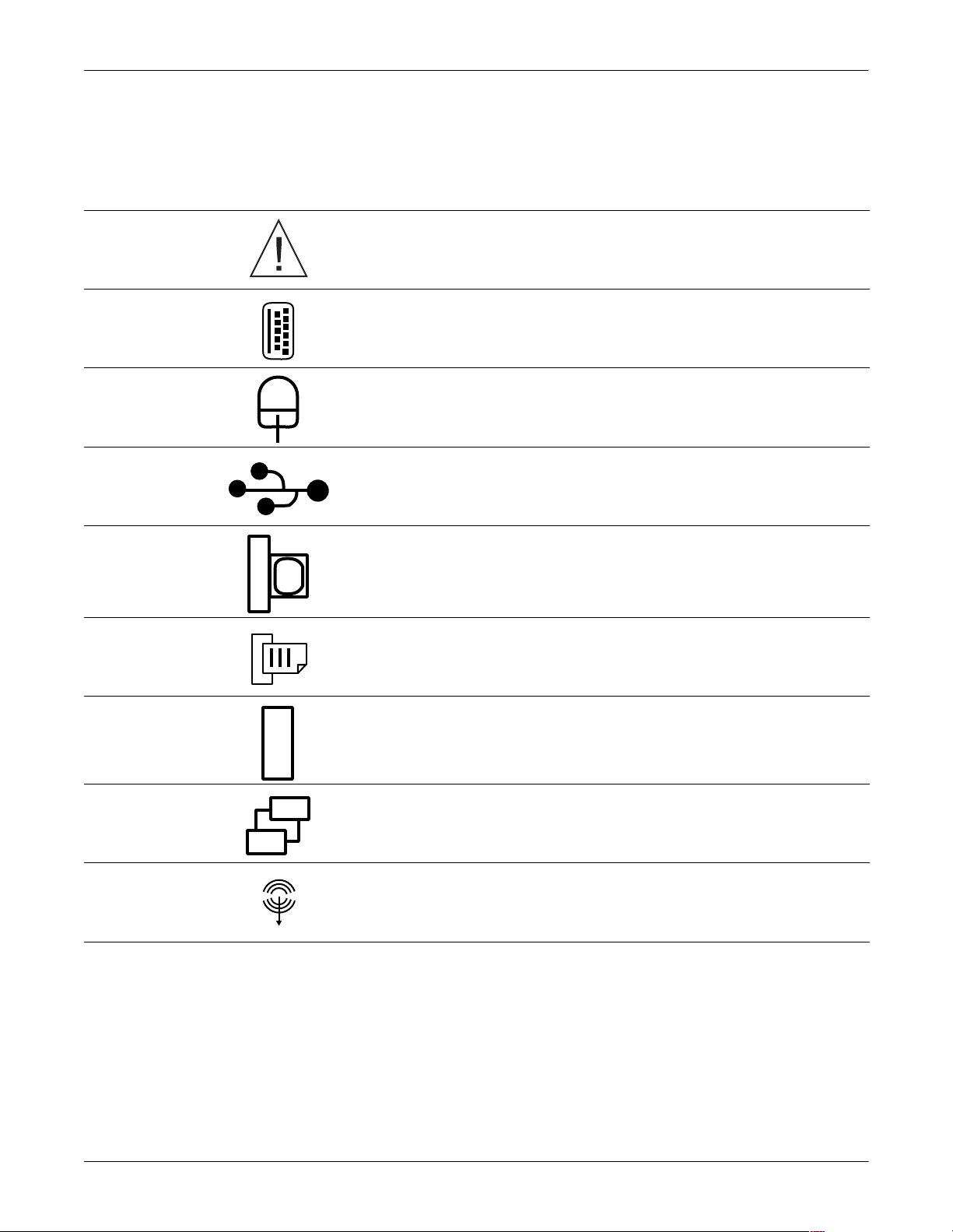
Equipment Symbols
The following symbol appears on the transmi tter.
ATTENTION: Consult accompanying documents before using the equipment.
KEYBOARD ICON: Denotes the keyboard port.
MOUSE ICON: Denotes the mouse port.
USB PORT ICON: Denotes the USB port. The USB port is NOT used on CIC or Unity
Network IS.
Introduction: Equipment Symbols
IOIOI
VGA MONITOR ICON: Denotes the VGA monitor port. Used only for Unity Network IS.
PARALLEL (PRINTER) PORT ICON: Denotes the parallel port into which the optional
laser printer is connected.
SERIAL COMMUNICATION (COM) PORT ICON: Denotes the communication (COM)
ports, used for optional service modem and optional PRN 50/PRN 50-M writer.
ETHERNET ICON: Denotes the Ethernet ports, used for the Unity Network MC, Unity
Network IX, and Unity Network RX/RS network connections. Optional Unity Network RX
(CIC/ApexPro) or RS (Unity Network IS/RSVP) port is on an additional Ethernet card.
SPEAKER OUT ICON: Denotes the speaker port connection.
Revision F CIC Pro and Unity Network IS Server 1-13
2001099-019
Page 22

Service Information
Service Requirements
Follow the service requirements listed below.
n
n
n
n
n
Introduction: Service Information
Refer equipment servicing to GE Medical Systems Information
Technologies’ authorized service personnel only.
Any unauthorized attempt to repair equipment under warr anty voids
that warranty.
It is the user’s responsibility to report the need for service to GE
Medical Systems Information Technologies or to one of their
authorized agents.
Failure on the part of the responsible individual, hospital, or
institution using this equipment to implement a satisfactory
maintenance schedule may cause undue equipment failure and
possible health hazards.
Regular maintenance, irrespective of usage, is essential to ensure
that the equipment is always be functional when required.
Equipment Identification
Every GE device has a unique serial number for identification. A sample of the
information found on a serial number label is shown below.
D 0 XX 0005 G XX
Month
Manufactured
A = January
B = February
C = March
D = April
E = May
F = June
G = July
H = August
J = September
K = October
L = November
M = December
Year
Manufactured
0 = 2000
1 = 2001
2 = 2002
3 = 2003
(and so on)
Product Code
Two-character
product descriptor
Product Sequence
Number
Manufacturing
number (of total
units
manufactured)
Division
F = Cardiology
G = Monitoring
Device Characteristics
One or two letters that further
describe the unit, for example:
P = prototype not conforming to
marketing specification
R = refurbished equipment
S = special product documented
under Specials part numbers
U = upgraded unit
Warranty
Standard warranty is one year.
1-14 CIC Pro and Unity Network IS Server Revision F
2001099-019
Page 23

2 Equipment Description
Revision F CIC Pro and Unity Network IS Server 2-1
2001099-019
Page 24

For your notes
2-2 CIC Pro and Unity Network IS Server Revision F
2001099-019
Page 25

Equipment Description: General System Information
General System Information
Network Information
Unity Network MC
The Unity Network MC (Mission Critical) network is the network that
is used to connect the server systems to the monitors and to the
telemetry cabinets. This network contains all the waveforms,
parameters, alarms and other time-sensitive data. The server should be
connected to the Unity Network MC backbone.
Unity Network IX
The Unity Network IX (Information eXchange) network is used by the
network laser printer and to interconnect the server systems for license
sharing between the server systems. The Unity Network IX network is
also used for the Full Disclosure option (CIC Pro) or the web browsing
option (Unity Network IS).
Unity Network RX
The Unity Network RX (Receiver eXchange) network, formally called
Unity Network RS on Unity Network IS servers, is the connection to
the ApexPro receiver for CIC Pro systems. This is a one-to-one link (i.e.,
only one receiver to one CIC Pro). If a hub is not used (not needed), you
must use a null or crossover cable. This network connection is also used
for the Unity Network IS RSVP option.The following tables specify the
physical location of the Unity Network connections for Nightshade and
BCM platforms for CIC Pro and Unity Network IS.
Revision F CIC Pro and Unity Network IS Server 2-3
2001099-019
Page 26

Network Connections
Equipment Description: General System Information
CIC Pro
CIC Pro Unity Network Connections
Unity Network
Connection
Unity Network MC Ethernet Port on CPU Ethernet Port marked “MC”
Unity Network IX Ethernet card on back of CPU Ethernet Port marked “IX”
Unity Network RX
(ApexPro only)
Nightshade Server BCM Server
Optional ethernet card on back
of CPU
Optional ethernet card on back
of CPU
Unity Network IS
Unity Network IS Unity Network Connections
Unity Network
Connection
Unity Network MC Ethernet Port on CPU Ethernet Port marked “MC”
Unity Network IX Ethernet card on back of CPU Ethernet Port marked “IX”
Unity Network RX (RS)
(RSVP only)
Nightshade Server BCM Server
Optional ethernet card on back
of CPU
Optional ethernet card on back
of CPU
Un-Interruptible Power Supplies
USP Installations
&$87,21
Connect the UPS to the PC CPU(s) and displays only. Do
NOT connect printers or other devices to a UPS. Other
devices my shorten estimated run times. If power is not
restarted in time the unit shuts down and patients will
not be monitored.
GE Medical Systems Information Technologies reco mmends the use of an
un-interruptible power supply (UPS) with the system. If a UPS is NOT
used, improper shut downs of the system could result in the event of a
power outage and cause a l engthy disk scan procedure when the unit
reboots. You could also lose data in the event of a power outage if you do
not use a UPS.
Follow the manufacturer’s recommendations for installing the UPS.
2-4 CIC Pro and Unity Network IS Server Revision F
2001099-019
Page 27

Equipment Description: General System Information
UPS Runtime Estimates and Options
Runtimes are expressed in hours:minutes. Typical runtimes based on
fully charged, new batteries operating under typi cal load conditions.
Runtimes are affected by:
n
Battery age,
n
Ambient temperat u r e,
n
Site specific UPS usage patterns, and
n
Load characteristics.
Your actual run time may be different.
Percent of Capacity ON400 ON600 ON900
UPS Runtimes (Hours:Minutes)
10 1:33 1:45 1:59
20 0:43 0:52 0:58
30 0:27 0:34 0:37
40 0:19 0:25 0:27
50 0:15 0:20 0:21
60 0:12 0:17 0:17
70 0:10 0:14 0:14
80 0:09 0:13 0:12
90 0:08 0:11 0:10
100 0:07 0:10 0:09
UPS Options
Type Description Limits
UPS4=A Oneac ON400XRA-HOE Domestic
120V 400VA, UL 1778, CSA 22.2
UPS6=A Oneac ON600A-HO Domestic 120V
600VA, UL 1778, CSA 22.2
Will power one Server and 21-inch
Display for approximately 10min.
Will power one Server and 21-inch
Display for approximately 30min.
Will power two Servers and two 21-inch
Displays for approximately 10min.
UPS4=Y Oneac ON4001-SN Intl. 220-240V
400VA, UL 1778, CSA 22.2
UPS6=Y Oneac ON6001-SN Intl. 220-240V
600VA, UL 1778, CSA 22.2
Will power 1 Server and 21-inch
Display for approximately 10min.
Will power one Server and 21-inch
Display for approximately 30min.
Will power two Servers and two 21-inch
Displays for approximately 10min.
UPS4=C Oneac ON900J-SN JAPAN 120V
50/60hZ 900VA, UL1778, CSA 22.2
Will power one Server and 21-inch
Display for a minimum of 30min.
Will power two Servers and two 21-inch
Displays for a minimum of 10min.
Revision F CIC Pro and Unity Network IS Server 2-5
2001099-019
Page 28
Equipment Description: General System Information
How Trends are Calculated
GE Medical Systems Information Technologies systems trend two types
of physiological data, periodic and episodic.
Periodic data is constantly upda ted. Examples of periodic data include
heart rate (HR) and blood pressure (BP). Episodic data are events that
are user or system generated. Examples of episodic data include
temperature (Temp) and non-invasive blood pressure (NiBP)
Periodic data is sampled ev ery two seconds to get 30 samples pe r minute.
The value that displays is the median of the 30 samples. Odd-number
values are rounded down to the nearest even-number. The value is
always the median of a one-minute time fra me, rega rdless of the int erval
selected. The interval simply defines which trended data displays (i.e.,
five minute intervals means the trended data are one-minute samples
spaced five minutes apart, NOT fi ve -minut e sa mples an d NOT a medi an
of the five one-minute samples from that period).
If the calibration of the system clock changes (for example, daylight
savings time), the “time” for periodic data “slides” into the revised time.
However, episodic data is time-stamped and retains its original time.
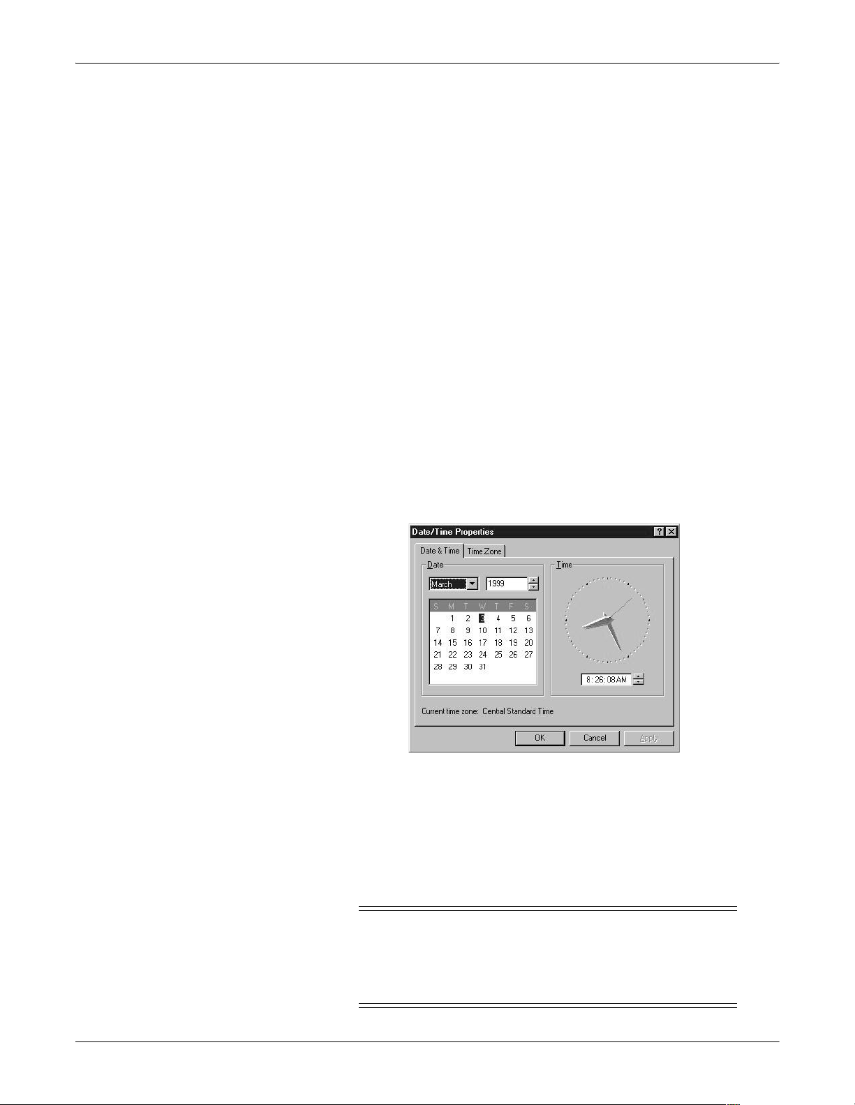
Time and Date Configuration
This option is used to adjust the CIC Pro and Unity Network IS Server
time and date settings. Any time/date changes made at one CIC Pro is
also transmitted over the GE Unity Network to all other devices. The
Time Master CIC Pro re-broadcasts the time/date change information
which causes all other devices to adjust their settings. The CIC Pro or
Centralscope with the highest IP address is the Time Master.
&$87,21
Any change to the time/date data causes all units on the
network to alter their time and date settings also. This
change may cause other monitors to alter the time
parameter of some patient data.
2-6 CIC Pro and Unity Network IS Server Revision F
2001099-019
Page 29

Equipment Description: General System Information
127(
You must manually make Daylight Savings Time changes in the
monitoring system. This change may affect patient data as noted
above.
Safe Shutdown Procedure
:$51,1*
Beds displayed on this server will be unmonitored while
the unit is shut down. Any ApexPro beds admitted o n a
shutdown CIC Pro will display “no com” if displayed at
other central stations and are not monitored.
If the need ever arises, it i s imp ortant to sh ut dow n the sy stem pr ope rly .
Follow this procedure to properly shut down your machine. This prevents
inadvertent errors from occurring during system shut down.
1. Open the Start menu located in the lower left corner of the Windows
NT main screen.
2. Select Shutdown... from the Start menu.
3. From the Shut Down Windows dialog you can either restart the
computer or shut it down. Select either Shut down the computer or
Restart the Computer to achieve your desired result.
If you are shutting the computer down prior to logo n, ho ld down the
following keys simultaneously:
Ctrl+Alt+Delete
Then, select the Shutdown button.
Revision F CIC Pro and Unity Network IS Server 2-7
2001099-019
Page 30

Equipment Description: CIC Pro and ApexPro System Components
CIC Pro and ApexPro System Components
Hardware
The CIC Pro system includes all of the Unity Network IS internal
components (excluding one of the Ethernet circuit boards), and also
contains the following:
n
1280 x 1024 x 65536 video card
n
16-bit sound card
n
2 external speakers
ApexPro Telemetry System
The ApexPro telemetry system includes all of the above internal
components listed for a CIC system, plus:
n
additional 128 MB RAM and
n
an additional processor
2-8 CIC Pro and Unity Network IS Server Revision F
2001099-019
Page 31

Equipment Description: CIC Pro and ApexPro Functional Description
CIC Pro and ApexPro Functional Description
CIC Pro
The CIC Pro (Clinical Information Center) application is connected to the
Unity Network MC network via Ethernet to provide real-time patient
data and alarms for central nurses’ stations in hospitals.
The CIC Pro can display real-time waveforms and vital sign data with
visual and audible alarms for up to 16 patients simultaneously. CIC Pro
supports both hardwire and telemetry data.
The software allows th e user t o s elect an y bed on the Uni ty Network MC
network and to display an expanded view of that bed’s real-time
parameters and waveforms. This expanded view also allows the user to
view and modify settings (within the care unit) and view other patient
data including alarm histories, graphic trends and tabular trends.
The system is user-con figurable for the number of patients to be
displayed, and the number of di splayed waveforms per patient.
Waveform colors are configurable.
All configuration data is stored, and is restored after a system power
cycle or software restart.
The system runs on the Microsof t Windows NT operati ng system (version
4.0 SP6 or later).
ApexPro Telemetry System
The ApexPro telemetry application is connected to the Unity Network
MC network via Ethernet to provide real-time patient data and alarms
for central nurses’ stations in hospitals and also connects to the Receiver
System via the Unity Network RX network.
ApexPro telemetry provides clinicians with patient physiological
information while allowing for patient mobility. The physiological
parameters monitored include ECG, non-invasive blood pressure, and
SpO
. This physiological information is sent to the CIC for processing
2
and display via Ethernet or the Unity Network MC network.
Printed Output
Patient data may al so be presented to the user in the following forms of
printed output:
n
Laser printer, or
n
PRN 50/PRN 50-M Digital Writer.
Revision F CIC Pro and Unity Network IS Server 2-9
2001099-019
Page 32

Equipment Description: CIC Pro and ApexPro Functional Description
Administrative and Service Access
Administrative and service users can interface to the server through
standard Windows NT tools. The software creates logs to record
significant events. Use standard Windows NT tools to load and update
software.
Logs
Error Logs
The software records the occurrenc e of fatal and nonfatal errors in a user
readable error log.
Connection Logs
The software records the us age of each available communication channel
by noting when a connection is established and which beds are viewed.
2-10 CIC Pro and Unity Network IS Server Revision F
2001099-019
Page 33

Equipment Description: CIC Pro Service Logons
CIC Pro Service Logons
General
The following procedures are for entering various levels of CIC Pro
software. Each logon provides a different level of accessibility. Follow
these steps to logon to the computer for these purposes.
&$87,21
The bed displayed at this CIC Pro is u nmonitored while
the CIC Pro is shut down. Any ApexPro beds admitted on
this CIC Pro PC display “no com” if displayed at other
centrals and are not monitored.
You must shut down the CIC Pro applicat ion before doing the logons.
It is also necessary t o Close All Programs And Log On As Different User
from Window’s start button. To run the program, log in as user
“administrator” from Wi ndow’s login screen. To get th e login screen to
come up you have to hold down Shift while Windows is starting.
Full-Access Logons
Site Administrator Logon
1. Select Setup CIC.
2. Select the Service Password tab.
3. Type mms_com as the Password.
4. In the command box that opens, type stop and then press Enter.
5. Click on Start then select Shut Down and Close All Programs And
Log On As Different User.
6. Hold down Shift and select Yes.
Continue holding until prompted for the password.
7. Choose from the following Logons and continue as instructed.
The following logons are “full-access” administrative accounts used to
update software and make changes in the operating system
configuration.
The two accounts are separate but similar accounts, one to be used by the
site administrator and the other to be used by field service personnel.
To logon as site administrator, complete the following when prompted for
logon:
User name: type administrator and press Tab.
Password: type admin1,3,5,7 and press Enter.
Revision F CIC Pro and Unity Network IS Server 2-11
2001099-019
Page 34

Equipment Description: CIC Pro Service Logons
CIC Pro Administrator Logon
To logon as CIC Pro System Administrator, complete the following when
prompted for logon:
Limited-Access Logon
The following logo n is a “l imited -acc ess” user a ccount a nd should be used
to review logs or restart CIC Pro.
For CIC Pro Limited Access logon, complete the following when
prompted for logon:
Run-Time Logon
User name: type cicadm and press Tab.
Password: type cicadm1,3,5,7 and press Enter.
User name: type cicuser and press Tab.
Password: type cicuser1,3,5,7 and press Enter.
The following logon is a “run time” user account and should be used to
restart CIC Pro to run in the normal user interface mode.
For CIC Pro Run-Time logon, complete the following when prompted for
logon:
User name: type CIC and press Tab.
Password: type cic and press Enter.
2-12 CIC Pro and Unity Network IS Server Revision F
2001099-019
Page 35

Equipment Description: CIC Pro IP Address Information
CIC Pro IP Address Information
Display All IP Addresses
To display all the IP addresses on the Unity Network IS server subnets:
1. Click on the Setup CIC button.
2. Click on the Service Password tab.
3. Position the cursor in the Password field and type mms_com. Click
on Apply.
4. Type ipconfig<space>/all and press Enter. The IP Configuration
information appears. (See the following example from the BCM
Server.)
Ethernet adapter E100B4:
Description. . . . . . . . : Intel(R) PRO Adapter
Physical Address. . . . . . : 00-10-F3-03-02-7F
DHCP Enabled. . . . . . . . : No
IP Address. . . . . . . . . : 121.64.68.1 (IX)
Subnet Mask . . . . . . . . : 255.0.0.0
Default Gateway . . . . . . :
Ethernet adapter E100B3:
Description . . . . . . . . : Intel(R) PRO Adapter
Physical Address. . . . . . : 00-10-F3-03-02-80
DHCP Enabled. . . . . . . . : No
IP Address. . . . . . . . . : 126.64.68.2 (ApexPro Host)
Subnet Mask . . . . . . . . : 255.0.0.0
IP Address. . . . . . . . . : 126.64.68.1 (MC)
Subnet Mask . . . . . . . . : 255.0.0.0
Default Gateway . . . . . . :
Ethernet adapter E100B2:
Description . . . . . . . . : Intel(R) PRO Adapter
Physical Address. . . . . . : 00-50-DA-15-75-3D
DHCP Enabled. . . . . . . . : No
IP Address. . . . . . . . . : 119.1.1.2 (RX)
Subnet Mask . . . . . . . . : 255.0.0.0
Default Gateway . . . . . . :
5. Close the Command Prompt window.
6. Close the CIC Setup window.
Revision F CIC Pro and Unity Network IS Server 2-13
2001099-019
Page 36

Equipment Description: CIC Pro IP Address Information
Change the Unity Network MC IP Address
Change the Unity Network MC IP Address for the CIC Pro Application
1. Use the mouse to select Setup CIC at the bottom of the screen.
2. From the CIC Setup screen, select the Service Password tab.
3. At the service password prompt, type mms_com and press Enter.
This enables the Service Menu and displays a command prompt
window.
4. To determine the current IP address: At the Command Prompt
window, type C:\Program Files\Marquette\CIC\x.x>ipaddr to
access the service utilities (x.x is the software version running on
your CIC).
5. To change the current Unity Network MC IP address: At the
Command Prompt window type C:\Program
Files\Marquette\CIC\x.x>ipadd r< sp ace>[ n ew add ress ] (x.x is
the software version running on your CIC).
Change the Unity Network MC IP Address for the Operating System
1. Logon as an administrator.
2. Go to My Computer>Control Panel>Network.
3. Click on TCP/IP Protocol to highlight it.
4. Click on the Properties button.
5. In the Adapter drop down menu, select the Unity Network MC
network card as shown in the following table:
CIC Pro Adaptor Selections
Unity Network/
Application
Unity Network MC for
CIC Pro & ApexPro
Host
Unity Network IX
ApexPro Rack
Adaptor for Nightshade Server Adaptor for BCM Server
[1] Intel EtherExpress PRO
Adapter
[2] 3Com Fast EtherLink XL NIC
(3C905B-TX)
[3] 3Com Fast EtherLink XL NIC
(3C905B-TX)
[3] Intel (R) PRO/100+
Management Adapter
[4] Intel (R) PRO/100+
Management Adapter
[2] Intel (R) PRO/100 S
Desktop Adapter
6. In the IP Address field enter the new settin gs for the CIC Pro Unity
Network MC IP address.
7. Optionally, in the IP subnet field enter the new settings.
127(
Typically the subnet mask should remain as 255.0.0.0.
8. Click OK.
2-14 CIC Pro and Unity Network IS Server Revision F
2001099-019
Page 37

Equipment Description: CIC Pro IP Address Information
9. Click Close.
10. When prompted with Do you want to restart your computer now?,
click Yes.
11. Wait for the CIC Pro to restart and monitoring to continue.
12. Verify all IP address and subnet mask changes by running ipconfig.
Change the Unity Network IX IP Address
1. Logon as an administrator.
2. For Adapter select the appropriate network card.
3. In the IP Address field enter the new settin gs for the CIC Pro Unity
Network IX IP address.
4. If necessary, update the Subnet Mask field to the appropriate
settings.
127(
Typically the ApexPro IP addresses and the Subnet Mask should
remain as the factory default.
Typically the Unity Network MC and Unity Network IX Subnet
Masks should be set to 255.0.0.0
5. Click OK.
6. Click Close.
7. When prompted with Do you want to restart your computer now?,
click Yes.
8. Wait for CIC Pro to restart and monitoring to continue.
9. Verify all IP address and subnet mask changes by running ipconfig.
Revision F CIC Pro and Unity Network IS Server 2-15
2001099-019
Page 38

Equipment Description: CIC Pro Setup Utility
CIC Pro Setup Utility
Several characteristics of the CIC Pro software can be customized to
some extent for each location. Items such as display formats, audio
volumes, and display intensity can be adjusted by the users. Those
changes are described in the operator’s manual.
Other configuration items may only be changed while in the Service
Menu (also referred to as Service Mode). These items are generally
configured only by the Biomedi ca l En gineeri ng or te chnical support st aff.
The CIC Pro defaults that may only be configured from withi n the
Service Menu are found on the following tabs within CIC Setup:
n
CIC Defaults,
n
Telemetry Unit Defaults,
n
Telemetry Alarm Control Defaults,
n
Current Telemetry Listings,
n
Display Format,
n
Screen Calibration,
n
Service Password, and
n
Full Disclosure Defaults.
To access the Service Mode:
1. Use the mouse to select Setup CIC at the bottom of the screen.
2. From the Setup CIC screen, select the Service Password tab.
3. When prompted for the service pa ssword, type mms_cic and press
Enter.
127(
When you are in Service Mode, a cross-shaped cursor replaces the
normal arrow cursor.
To exit the Service Mode:
n
If the CIC Setup window is open, click the X button located at the
upper right corner of the window to exit the Service Mode.
n
If the CIC Setup window is closed, click on the Setup CIC button at
the bottom of the screen and click Yes to exit the Service Mode.
2-16 CIC Pro and Unity Network IS Server Revision F
2001099-019
Page 39

Equipment Description: CIC Pro Telemetry Tower Option
CIC Pro Telemetry Tower Option
The TELEMETRY TOWER option includes several selections that allow
new software to be loaded into a CD Telemetry
assembly through its floppy disk drive. The software up-load process for
the telemetry tower is controlled entirely through the CIC Pro system,
since the tower does not have an input device (such as a keyboard). An
alternative is to con nect a personal computer or laptop to the cabinet
assembly to load new software.
To upload software into the Telemetry Tower:
1. The Telemetry Tower function is invoked from t he Windows NT
Command Prompt window. To invoke t he Tel eme try Tow er funct ion,
type the following command: cicadmin.
The following window appears:
®
–LANTM cabinet
2. Click on the arrow next to the Tower box to open the drop down menu
of tower names.
127(
Each tower (cabinet assembly) is described by its Care Unit
name and Ethernet address. The Ethernet address is used since
the towers are not named as monitors are.
3. Click on the desired name to select it
or
Enter a name in the Tower name box and pr e s s Enter.
4. Insert the floppy disc into the floppy disc drive of the Telemetry
Tower and click on Load Software from Floppy.
:$51,1*
Perform software uploads according to the update
instructions that accompany the software. Improper use
of this option may result in loss of patient monitoring or
patient data. Do NOT uplo ad software unless instructed
to do so by qualified service personnel and only after the
telemetry system is properly prepared.
Revision F CIC Pro and Unity Network IS Server 2-17
2001099-019
Page 40

Equipment Description: CIC Pro Telemetry Tower Option
5. If necessary, click on Reboot Tower to reboot the CD Telemetry–LAN
cabinet.
127(
A reboot causes a loss of patient monitoring functions while the
software restarts the CD Telemetry–LAN cabinet power. Make
arrangements for interim monitoring of patients before rebo oting
any cabinet.
Use this option in two circumstances:
n
To reboot the cabinet, if as a result of troubleshooting you decide that
the cabinet should be rebooted,
n
To start the operation with newly-installed software. Software is
uploaded into the cabinet in the background and only used when the
cabinet has rebooted.
The procedure to reboot to initiate new software is the same as the
troubleshooting reboot. The same concerns about loss of patient
monitoring apply.
127(
Make sure you notify the responsible personnel for the admitted
patients (monitored by the CD Telemetry–LAN cabinet that is
rebooted) that the cabinet will be rebooted and they will lose patient
monitoring for a few minutes.
:$51,1*
During the reboot period monitoring functions are lost.
The buttons for the “lost” patients change on the central
stations to show ADMIT. This may lead some monitoring
system users to get the “lost” patients back by
readmitting them. Instruct all personnel NOT to admit
any of the “lost” patients during reboot. Once the cabinet
finishes rebooting the “lost” patients return
automatically. Note that when you activate new
software, all patient histories and trends are lost.
2-18 CIC Pro and Unity Network IS Server Revision F
2001099-019
Page 41

Equipment Description: CIC Pro Full Disclosure License Management Setup
CIC Pro Full Disclosure License Management Setup
BCM Server
Each CIC Pro with version 3.x software comes with the ability to store 16
beds of Full Disclo sure (FD) da ta for one hour without a license . CIC Pros
with the Full Disclosure option and version 3.x software has the ability to
store up to16 beds for 72 hours with the appropriate licenses and license
settings.
When operating two CIC Pros withi n the sa me “care unit” where one has
the Full Disclosure option and the other does not, it is necessary to turn
Full Disclosure OFF on the CIC Pr o without the Full Disclos ure option t o
prevent a conflict with th e two diffe rent sto rage ca paciti es of t he C IC Pro
units.
Nightshade Server Without Full Disclosure
The Nightshade platform may require a hardware modification to
support anything greater than 1-hour Full Disclosure. However, for
those Nightshade PCs that do not have a F drive and have purchased
Full Disclosure licenses within the care unit, you must perform the
following steps to disable Full Disclosure on this PC.
1. Select Setup CIC an d c lick on th e Service Password tab.
2. Type mms_com and press the Enter key.
3. Type fdcmd -n OFF and press the Enter key. Beds that were full
disclosed on this PC are now deleted.
4. Type stop.
5. Select Start > Shutdown > Close all programs and log on as a
different user. Allow the CIC to boot up in CIC mode.
6. Wait a few minutes and type fdcmd -lu and verify beds are now full
disclosed on another CIC that support >1-hour Full Disclosure
storage.
7. Type exit and close all open windows.
Revision F CIC Pro and Unity Network IS Server 2-19
2001099-019
Page 42

Equipment Description: ApexPro PTSCONFIG Utility
ApexPro PTSCONFIG Utility
The PTSCONFIG utility is a console application that allows you to
configure the ApexPro application. Access the PTSCONFIG utility via
the command prompt window.
display Commands
The commands listed below display ApexPro application information.
Command displays...
help list of available commands
tower ApexPro tower’s full name “UNIT|NAME”
software software versions for all running software (main, rack, etc.)
Table 2. display Commands
build date/time the software was built
patient patient information: TTX, tower, and receiver numbers
patreceiver information about the patient’ receiver and transmitter
IP IP address used by the ApexPro application to talk to the Unity
Network
rack IP address used by the ApexPro application to talk to the rack
network
receiver receiver/unit assignments for this ApexPro tower
ttx network-wide in-use TTX list (from the TTX master list)
unitlist network-wide unit/receiver list (from the TTX master list)
2-20 CIC Pro and Unity Network IS Server Revision F
2001099-019
Page 43

modify Command
Equipment Description: ApexPro PTSCONFIG Utility
The commands liste d be low pe rm it mod if ications to the ApexPro
application.
Table 3. modify Command
Command allows modification to...
unit ApexPro tower’s unit name
tower ApexPro tower’s device name
ip IP address used by the ApexPro application to talk to the Unity
Network
rack IP address used by the ApexPro application to talk to the rack
network
receiver receiver/unit assignments for this ApexPro tower
ttx displays a network-wide in-use TTX list (from the TTX master list)
listwhat Command
unitlist displays a network-wide unit/receiver list (from the TTX master list)
For information on using the listwhat command, refer to “List Network”
in the Troubleshooting chapter.
Revision F CIC Pro and Unity Network IS Server 2-21
2001099-019
Page 44

Other Commands
Equipment Description: ApexPro PTSCONFIG Utility
The table below lists other ApexPro software commands.
Other Commands
Command function...
admit admits a patient on this ApexPro tower (“admit” shows usage)
discharge discharges a patient on this ApexPro tower (“discharge” shows
usage)
dload downloads rack software (“dload” shows usage)
resetrack immediately (with no confirmation) resets all racks connected to
the tower
blink
patient
rack
receiver
stop
boot reboots the PC (“DDMM” password required: confirmation is also
shutdown restarts ApexPro application (“DDMM” password required:
statistics
waveform
wavereset
histogram
histreset
storeecg stores a file containing raw patient ECG sample data
blinks rack LED(s) according to:
entered patient name (UNIT|BED)
entered ApexPro tower IP address
entered ApexPro tower IP address and receiver number
stop any blinking
requested)
confirmation is also requested)
displays ApexPro software performance statistics:
waveform data latency timing through ApexPro software
reset waveform data latency timing counters
waveform data timing through ApexPro software
reset waveform data timing counters
2-22 CIC Pro and Unity Network IS Server Revision F
2001099-019
Page 45

Equipment Description: Unity Network IS System Components
Unity Network IS System Components
Hardware
The Unity Network IS system uses a PC tower with th e choice of a 15inch, 17-inch, or 20-inch color computer display. The entire system is
assembled, loaded with software, and then shipped as a complete unit
ready for setup and use.
To run the Unity Network IS system the PC tower comes with the
following internal components:
Nightshade Server
The Nightshade server includes the following hardware:
n
SCSI internal hard disk drive,
n
CD-ROM drive,
n
High density floppy disk drive,
n
Integral video controller (one),
n
256kB DRAM video memory module,
n
Integral audio controller (one),
n
Ethernet PCI (PC interface) plug-in circuit board (two), and
n
Dual CPU.
BCM Server
RSVP System
The BCM server includes the following hardware:
n
SCSI internal hard disk drive,
n
CD-ROM drive,
n
High density floppy disk drive,
n
Integral video controller (one),
n
256kB DRAM video memory module,
n
Integral audio controller (one),
n
Ethernet PCI (PC interface) plug-in circuit board (one), and
n
Single or Dual CPU.
The RSVP system includes all of the above internal components and the
following external components:
n
a terminal port server and
n
a modem rack with a capacity for twelve modems.
Revision F CIC Pro and Unity Network IS Server 2-23
2001099-019
Page 46

Equipment Description: Unity Network IS Functional Description
Unity Network IS Functional Description
The Unity Network Information Suite (IS) Server consists of an IBM
compatible personal computer (PC) that is connected to the Unity
Network MC network to act as a patient monitoring network fil e server.
The server runs on the Microsoft Windows NT operatin g system and
provides various applications with technical and clinical data from
patient monitors and other devices connected to the GE Unity Network.
Currently the following software applications are available for the Unity
Network IS server:
n
RSVP (Remote System for Viewing Patients; V4.2 or earlier),
n
AVOA (Automatic View on Alarm; V2 or greater),
n
HL7 Outbound (V3 or greater),
n
ICMMS (Integrated Computer Material Management System; V3 or
greater), and
n
Service Web pages (V3 or greater).
RSVP Option
Remote System for Viewing Patients (RSVP) allows access to the Unity
Network MC network over ordi nary phone li nes. Using a P C and modem,
clinicians can view four real-time waveforms and all vital signs from any
monitor or telemetry device on the Unity Network MC network in the
hospital.
The Unity Network IS Server is attached to the Unity Network MC
network and the RSVP client software for use by the clinician. The server
is configured with an external modem rack that can hold up to twelve
modems to permit up to twelve simultaneous server connections.
The port server provides a connection between the serial lines of the
modem and the server using a dedicated ethernet connection.
The server monitors network traffic on the Unity Network MC network
to build a list of available bedside and telemetry products. It also
manages the traffic from the modems that are used for incoming client
requests.
The required software consists of:
n
The RSVP Server Application and
n
The RSVP Remote Program.
The remote program is designed to run on a 486DX2 PC with 9600 baud
modem. The remote program can run on the Windows NT, Windows 95,
Windows 3.1 or DOS operati ng sy st ems.
127(
Disable the screen saver when you run this applicat ion. The screen
saver could interfere with the RSVP program.
RSVP and Auto View can run on separate systems or be combined to
run on the same server.
2-24 CIC Pro and Unity Network IS Server Revision F
2001099-019
Page 47

Waveform Data
Server Status
Equipment Description: Unity Network IS Functional Description
The remote client requests waveform data by unit/bed name. After the
request, the server continues to send a waveform response every quartersecond. Each waveform response contains 15 data points for each of the
waveforms. Data is sent for up to four waveforms. The four waveforms
sent are dependent on the display order set, top to bottom, at the selected
bedside.
The response also contains scaling information. You can direct the
remote client:
n
To use an absolute scale passed in the response or
n
To auto scale the data to fit in the available window size.
The response can indicate if the data for the waveform is invalid. This
indication means all data for that particular quarter-second is invalid.
The remote client requests the server status while simultaneously
providing its own status.
Auto View Option
Remote client status includes:
n
Executing software revision
n
Site name
n
User name
Server status includes:
n
Available remote client software revision
n
Path name to remote client image
With the Auto View application you can monitor alarm broadcasts from
the bedside monitors. When it detects a new alarm, the application
clones the alarming bed and notifies the other beds in the unit that an
alarm is occurring. The other beds may choose to float the alarm
information from the cloned bed. When you clear or silence the alarm,
the other beds in the unit ar e notified and the clone is terminated
Only choose one alarm at a time for a unit. If there is more than one
alarm active, the highest priority, oldest alarm is chosen. Once the alarm
is chosen, it remains the chosen alarm for the unit until the condition is
cleared or silenced, even if a higher priority alarm occurs.
127(
RSVP and Auto View can run on separate systems or combine them
to run on the same server.
Revision F CIC Pro and Unity Network IS Server 2-25
2001099-019
Page 48

Equipment Description: Unity Network IS Functional Description
HL7 Outbound Option
ICMMS Option
The HL7 Outbound software provides the inte rface between the Unity
Network IS Server software, the Unity Network MC network and the
HIS server software. The HL7 Outbound Interface Software acts as the
client by sending unsolicited HL7 Outbound messages to the HIS server.
The software manages the connections with the HIS servers and
maintains logs to track errors and connection statistics.
The Integrated Computer Material Management System (ICMMS)
application provides information about devices attached through the
Unity Network MC network and provi des this information to other GE
Medical Systems Information Technologies applications and to third
party applications. The collected information assists in asset control and
is not intended for clinical use. The information discovery varies based on
the type of device and the device software revision. New software
released for devices enhances the ability of devices to return information
to the ICMMS application and in turn enrich the users of this
information.
In versions V4.1 and later with parameter update functionality, ICMMS
will collect data for up to 350 monitoring devices. The data collection
proceeds serially until data for all devices has been colle cted. The time
required to complete one update loop is dependent on the total number of
network devices and the current network traffic load. The average
update time required to retrieve all ICMMS data from one Unity
Network device is approximately ten seconds. Therefore, the average
update time is approximately one hour, given a network with 350
devices. This time is only an average and may be significantly longer
depending on the current network load.
Typical information collected by ICMMS includes:
n
Device type
n
IP address
n
Ethernet address
n
Serial number
n
Location
n
Admission status
n
Software revision of the device’s components
®
St. Croix Systems, Inc.
WOSYST™ equipment management software is
a third party application that uses the informatio n collected by the
ICMMS application. WOSYST
is sold separately and is not part of this
software release.
2-26 CIC Pro and Unity Network IS Server Revision F
2001099-019
Page 49

Equipment Description: Unity Network IS Functional Description
Service Web Option
Logs
The Service Web pages provide a web browser interface to the Unity
Network IS operational information. The collected information assists in
service and maintenance of th e Unity Network IS equipment and is not
intended for clinical use. The web pages provide the following
information:
n
ICMMS device information,
n
Alarm Status,
n
RWHAT data synopsis, and
n
Intel® Server Control Console access (Nightshade box only).
A utility exists for maintaining most logs. The common characteristic of
these logs are as follows:
n
Each log is stored in its own subdirectory.
n
Each day’s log is stored in its own file with the date encoded in the
name.
n
Each entry in the log file is time stamped.
n
Dates and times are all based on Greenwich Mean Time.
n
Daily file sizes are limited to 30 megabytes.
Error Logs
Event Logs
The software records the occurrenc e of fatal and nonfatal errors in a user
readable error log.
The RSVP Event Log – records the usage of each available RSVP
modem communication channel by noting when a connection is
established and which beds are viewed.
The Auto View Event Log – Records the beginning and end of each
alarm along with other information.
The ICMMS Event Log – Records activity information including
statistics on device data acquis iti on and da ta ret riev al .
The HL7 Outbound Event Log – Records the acknowledgments for
HL7 Outbound messages received by the HIS server(s) for all beds
that data is collected for on the Unity Network MC network when
two or more time intervals of data are transmitted. It also records:
u
When beds are discharged, removed, or added on the network;
u
PID changes; and
u
When unit or bed name changes occur.
Revision F CIC Pro and Unity Network IS Server 2-27
2001099-019
Page 50

Equipment Description: Unity Network IS Service Logon
Unity Network IS Service Logon
The following logon is a “full-acce ss” administrative account used to
update software and make changes in the operating system
configuration.
1. On the keyboard simulta neously press Ctrl+Alt+Delete.
2. When prompted for logon:
User Name: type administrator and press Tab.
Password: type admin1,3,5,7 and press Enter.
2-28 CIC Pro and Unity Network IS Server Revision F
2001099-019
Page 51

Equipment Description: Unity Network IS Configuration Utility
Unity Network IS Configuration Utility
Control Functions
The Configuration Utility can be used to monitor and control the server
software. To start the progra m, double click on the MPIS Config icon
located on the left edge of the screen.
The Control Functions area of the General tab can be used to monitor and
control the program.
Button Descriptions
The following is a list of each button in the Control Functions field along
with a description of each button’s function.
Start Unity Network IS (or Start Unity–IS)
This button starts the server applications. As normally configured, the
software automatically starts when the computer starts. Activating this
button also starts a 90-second interval which updates the Number of
Instances Running fields described later in this section.
Stop Unity Network IS (or Stop Unity–IS)
This button stops all server applications. This button also starts a 90second interval to update the Number of Instances Running fields.
Save Config Data
This button allows saving configuration changes made under any of the
“tabs” without exiting the program.
Start Updates
This button starts a 90-second interval which updates the Number of
Instances Running field.
Number of Instances Running
The Number of Instances Running field presents information ab out the
current status of the server software. This area is updated as long as the
Remaining update time is not displaying Off in the Seconds box. Always
push the Start Updates >> button prior to using the information in the
Number of Instances Running area.
Revision F CIC Pro and Unity Network IS Server 2-29
2001099-019
Page 52

Box Descriptions
Equipment Description: Unity Network IS Configuration Utility
The following is a list of boxes within the Number of Instances Running
area along with a description of what each box represents.
Unity (or Unity IS)
This box should be “1” if the server applications are started. It should
be “0” if the server is not running.
gbds (active beds)
This box should be “0” if the server applications are not running.
When running, this number varies depending on the number of
bedside monitors being used by the server applicat io n.
RSVP (Version 4.2 and Earlier)
This box should be “1” if the server applications are started and
RSVP is enabled on the RSVP tab. It shou ld be “0” if the server
applications are not running or RSVP is not enabled on the RSVP
tab.
Auto View
This box should be “1” if the server applications are started and Auto
View is enabled on the Auto View tab. It should be “0” if the ser ver
applications are not running or Au to View i s not e nabled on the Auto
View tab.
bootp
This box should always be “1” if the server is configured to support
RSVP. The bootp service is started automatically on RSVP servers
and is independent of the GE Unity Network Information Suite
Server applications.
HL7
This box should be “1” if the server applications are started and HL7
Outbound is enable d on th e HL7 tab. It should be “0” if the server
applications are not running or HL7 Outbound is not enabled on the
HL7 tab.
ICMMS
This box should be “1” if the server applications are started and
ICMMS is enabled on the ICMMS tab. It should be “0” if the server
applications are not running or ICMMS is not enabled on the
ICMMS tab.
2-30 CIC Pro and Unity Network IS Server Revision F
2001099-019
Page 53

Equipment Description: Unity Network IS Configuration Utility
RSVP Port Status (Version 4.2 and Earlier)
On the RSVP tab, the status of each RSVP Port is displayed. The port
status can be in one of the four states listed below:
Unknown
If RSVP is not running or no st atus updates have been received a “?”
appears in the Port Status text field to indicate an unknown state.
Port Disabled
If RSVP is running but the Active Ports check box is empty or if the
port failed to initialize correctly, Port Disabled appears in t he status
text field.
Waiting Call
If RSVP is running and the Act ive Ports check box is checked, and the
port was initialized correctly, Waiting Call appears in the stat us t ext
field.
Call Active
When a call is received on an enabled port and communications has
been established with the remote client, Call Active appears in the
status text field.
Revision F CIC Pro and Unity Network IS Server 2-31
2001099-019
Page 54

Equipment Description: Unity Network IS Port Server Firmware
Unity Network IS Port Server Firmware
Use this procedure if it becomes necessary to update the firmware in the
Central Data port server. To update the firmware:
1. Stop the Boot server as follows:
a. Go to Start>Settings>Control Panel and open the Services menu.
b. In the Services pop-up menu, select Bootpd NT.
c. Select the STOP button, reply Yes to the Are you sure? prompt.
Under the STATUS column, the message STARTED should
disappear. Select CLOSE to cl ose that menu.
2. From the main screen, open the Start menu and select Command
Prompt. At the c:\ prompt type
cd<Space>c:\Program<Space>Files\Us\bin\elupdate and
press Enter.
127(
More detailed instructions can be found in the
“README.TXT” file in this directory.
Then at the c:\elupdate>_ prompt, type start <Space> /b
<Space> bootp and press Enter.
At this point the Mini Bootp Server window appears on the screen.
Bring the c:\elupda te window to the front l ayer, maki ng it t he a cti ve
window, and type s tart <Space> /b <Space> tftpd and press
Enter.
At this point the TFTP Server window appears on the screen.
3. Power cycle the port server. The LEDs flash at various rates during
the download process. Once the download is complete, the LEDs
remain steady on. Check the TFTP Server window. It should display:
Client: 1.1.1.1 (port server IP address)
Filename: el16.prm
Status: Transfer Complete!
4. Close the TFTP Server window and type
start<Space>/b<Space>verlog
At this point, the Version Information window appears on the screen.
5. Select MENU from the list, then select EDIT ADR and enter the port
server IP address by typi ng:
1.1.1.1
Select the OK button
6. Read the version information that appears. Verify that firmware
version 5.9 or later appears.
7. Close all of the windows to exit and return to the main screen.
8. Restart the computer.
2-32 CIC Pro and Unity Network IS Server Revision F
2001099-019
Page 55

3 CIC Pro/ApexPro
Installation &
Configuration
Revision F CIC Pro and Unity Network IS Server 3-1
2001099-019
Page 56

For your notes
3-2 CIC Pro and Unity Network IS Server Revision F
2001099-019
Page 57

CIC Pro/ApexPro Installation & Configuration: Pre-Installation Requirements
Pre-Installation Requirements
Read and fully understand the pre-installation requirements. Verify all
requirements are met before attempting installation of the CIC Pro
system.
Site Requirements
The computer tower is capable of producing heat and must be physically
located to allow the heat load to be adequately dissipated. The site
requirements listed below were written specifically for an Intel computer
tower.
:$51,1*
SERVER LOCATION — The computer server is
UL 1950/IEC 950 certified equipment which may not
meet the leakage requirements of patient care area
equipment. This equipment must not be located in the
patient vicinity as a shock hazard may exist, unless the
medical electrical system standard, IEC 60601-1-1 is
followed.
Environmental Limits
Failure to adequately ventilate the computer tower may
cause equipment failure or improper operating conditions
which may endanger the patients being monitored.
&$87,21
Do not locate the computer tower or display in an
enclosed area that may restrict dissipation of the heat
generated by the components. Any air flow restrictions
may cause a rise in internal temperature which may
result in equipment failu re. The computer tower uses an
internal forced air cooling system, but most displays do
not.
The user must determine the heat dissipation
requirements of the s elected display and design a
ventilation system accordingly.
The server operates reliably within normal office environmental limits.
Select a site that meets these criteria:
n
Clean and relatively free of excess dust.
n
Well ventilated and away from sources o f heat.
n
Away from sources of vibration or physical shock.
Revision F CIC Pro and Unity Network IS Server 3-3
2001099-019
Page 58

CIC Pro/ApexPro Installation & Configuration: Pre-Installation Requirements
Electromagnetic Fields and Electrical Noise
The server should be isolated from strong electromagnetic fields and
electrical noise produced by electrical devices such as elevators, copy
machines, air conditioners, large fans, large electric motors, radio and
TV transmitters, and high frequency security devices.
Clearance and Airflow
The site should provide sufficient clearance b ehind and around the
server to ensure prop er cooling a nd airflow. Keep ventil ating opening s on
the server free of obstructions.
Allow about 31 centimeters (12.2 inches) of clearance in back of the
server, 60 centimeters (23.6 inches) on the sides, and 22 centimeters (9
inches) in front.
Access Space
Plan access space for server maintenance. Make sure t here is conve nient
access to disconnect the AC power cord from the wall outlet or from the
back of the server, because disconnecting the cord is the only way to
remove AC power from the server before doing maintenance or upgrade
procedures. Pressing the DC push-b utton on/off switch on the front panel
does NOT remove server AC power.
Physical Specifications
Table 1. Physical Specifications
Nightshade Server BCM Server
Height 49.02 cm (19.3 inches) 42.2 cm (16.6 inches)
Width 21.04 cm (8.3 inches) 20.1 cm (7.9 inches)
Depth 44.96 cm (17.7 inches) 48.0 cm (18.9 inches)
Weight
17.1 kg (38 lbs.) minimum configuration
22.9 kg (51 lbs.) maximum configuration
11.3 kg (25 lbs.) minimum configuration
13.1 kg (29 lbs.) maximum configuration
3-4 CIC Pro and Unity Network IS Server Revision F
2001099-019
Page 59

CIC Pro/ApexPro Installation & Configuration: Pre-Installation Requirements
Power Requirements
Duplex Wall Receptacles
&$87,21
Loss of power to the computer tower results in loss of
patient monitoring capabilities to the system, and to any
remote display monitors connected via hardwire or
modem.
Two properly grounded duplex wall receptacles should be provided for
each system. Additional receptacles may be required to accommodate
peripheral equipment connected to the system. The wall receptacles
must be installed in an approved junction box. Use only three-prong,
polarized, hospital-grade wall receptacles to accept the three-prong
polarized plug on the computer equipment.
Un-Interruptible Power Supply (UPS)
GE Medical Systems Information Technologies recommends the use of a
UPS with the system. If a UPS is NOT use d, impro per shu t dow ns of the
system could result in the event of a power outage and cause a lengthy
disk scan procedure when the unit reboots. You could also lose data in
the event of a power outage if you do not use a UPS.
&$87,21
Connect the UPS to the PC CPU(s) and displays only. Do
NOT connect printers or other devices to a UPS. Other
devices my shorten estimated run times. If power is not
restarted in time the unit shuts down and patients will
not be monitored.
Revision F CIC Pro and Unity Network IS Server 3-5
2001099-019
Page 60

CIC Pro/ApexPro Installation & Configuration: Pre-Installation Requirements
Equipment Grounding
:$51,1*
SHOCK HAZARD — The computer tower and all
peripheral equipment must be adequately grounded or a
shock hazard may exist.
The grounding pin of all wall receptacles and all exposed metal parts
(beds, radiators, water pipes, etc.) in any patient area should be
electrically connected together. This common ground point should be
connected to the nearest equipotential ground through a bonded
grounding system, or with a 10 AWG stranded copper grounding cable.
The equipotential ground point should be as close to earth ground
potential as possible. If a bonded grounding system is not available, the
ground pin of each wall receptacle must be individually connected to a
central grounding point. Do NOT jumper from ground pin-to-ground pin
of the receptacles.
The grounding system must not carry current, such as a grounded
neutral, since the current flow will produce potential differences along
the ground path. These potential differences are a shock hazard source
for equipment users and pati ents.
Do NOT use conduit as a ground conductor. Plastic (PVC) piping or
fittings used in the conduit runs can break the electri c al connection to
ground, resulting in potential shock hazards.
The electrical grounding syst em should be conne cted on an earth g round.
If this is not possible, then a good ground reference such as a metal water
pipe or an electrically-conductive building component should be used. it
is more important that all grounded objects in the patient area are at the
same ground potential rather than at earth ground potential.
3-6 CIC Pro and Unity Network IS Server Revision F
2001099-019
Page 61

CIC Pro/ApexPro Installation & Configuration: CIC Pro Installation
CIC Pro Installation
:$51,1*6
CIC V3.x is NOT in-unit compatible with prior versions
of CIC or an y version of Centralscope. Sharing of the
same care unit name across central stations having
incompatible software versions can result in lost or
corrupted telemetry alarm defaults data and loss of
audible alarms.
Do not exceed a maximum of 15 CICs in a single logical
care unit. Both hardwire and telemetry beds are limited
in the number of remote view connections that can be
supported. Attempting simul taneous displays of a patient
monitor (bedside or telemetry) at too many CICs may
cause lost or intermittent communication between CICs
and the patient monitor. This is evidenced by NO COMM
or intermittent communication conditions for the beds.
The maximum CICs viewing a patient monitor can vary
depending on patient monitor capabilities and network
design.
:$51,1*6
External equipment must be connected to the system
only by qualified biomedical engineering perso nnel.
A shock hazard may exist if external devices are
connected other than as described in this manual, or as
directed by the manufacturer.
Only external devices specifically designed to be
connected to the PC tower, or approved by GE Medical
Systems Information Technologies for use with this
system, should be connected, as specified in this manual
or as otherwise spe cif ied b y the manu f actu re r .
&$87,21
All external cabling used with the server systems must
be routed so as not to interfere with access or operation of
the system.
All cabling must be installed to protect against tripping
and accidental disconnection of the cables.
Do NOT apply power until all eq uipment is in st alled a nd
ready for use.
Revision F CIC Pro and Unity Network IS Server 3-7
2001099-019
Page 62

CIC Pro/ApexPro Installation & Configuration: CIC Pro Installation
Pre-Installation Check
&$87,21
This assembly is static sensitive and should be handled
using precautions to pre vent electrostatic discharge
damage.
1. Remove all equipment, including all peripheral devices, from the
shipping cartons and inspe ct for damage.
2. Identify all required cables and prepare them for installation.
3. Verify AC power is available for the computer tower and all
peripheral equipment. Make sure the power supplies are installed,
tested, and ready for use in accordance with the pre-installation
requirements. This includes testing for proper grounding of the
power source.
4. Verify the desired physical location for the computer tower is in
accordance with the site requirements. Place the computer at the
selected site.
Connect Keyboard and Mouse
Connect the keyboard and mouse cables to the back of the PC tower.
NIGHTSHADE SERVER
Mouse
Cable
MOUSE
PORT
COM1
SERIAL
PORT
Keyboard
Cable
KEYBOARD
PORT
COM2
SERIAL
PORT
PARALLEL
PORT
Keyboard
KEYBOARD
PORT
BCM SERVER
Cable
Mouse
Cable
MOUSE
PORT
PARALLEL
PORT
COM2
SERIAL
PORT
ETHERNET
PORT
ETHERNET
PORTS
3-8 CIC Pro and Unity Network IS Server Revision F
2001099-019
Page 63

CIC Pro/ApexPro Installation & Configuration: CIC Pro Installation
Install the Speakers
NIGHTSHADE SERVER
SOUND
CARD
BCM SERVER
SOUND
CARD
SPK OUT
Speaker
Cable
Speaker
Cable
SPK OUT
Speaker
Output Icon
1. Identify the speaker output jack on the sound card at the ba ck of the
PC tower. The speaker output jack is labeled SPK OUT or marked
with an icon.
Strain Relief Bracket
2. A bracket is used as a strain relief and to hold the speaker connector
in place. Loosen the screw on the bracket just enough to insert the
speaker connector through the bracket hole and into the speaker
output jack. Make sure the connector is seated properly, then tighten
the strain relief bracket screw to hold it in place.
127(
Accidental disconnect of the speaker cables will result in loss of
audible patient alarms at the CIC monitoring location. Make sure
the speaker connections at the PC tower and the speakers are
properly secured with the provided strain relief brackets.
Revision F CIC Pro and Unity Network IS Server 3-9
2001099-019
Page 64

CIC Pro/ApexPro Installation & Configuration: CIC Pro Installation
Install the Power Cord
Cable Clamp
AC Power Cord
Case Screw
REAR VIEW OF TOWER
1. Remove the upper right case screw from the rear of the chassis.
2. Plug the AC power cord into the PC tower.
3. Install the provided cable clamp around the AC power cord
approximately 15 cm (6 in.) from the server connection end.
4. Secure the cable clamp to the chassis with the case screw installed in
the upper right case hole. Tighten the screw.
Connect the Video Display Monitor
Monitor
Cable
VIDEO
CARD
NOTE: These connectors are not used
and may not exist on some units.
127(
Do not connect to the v ideo conne cti on o n t he mot her boa rd ( near t he
parallel port connector).
Connect the video display monitor cable to the video card connection at
the back of the PC tower.
3-10 CIC Pro and Unity Network IS Server Revision F
2001099-019
Page 65

CIC Pro/ApexPro Installation & Configuration: ApexPro Option Installation
Connect the Digital Writer Printer
NIGHTSHADE SERVER
COM2
SERIAL
PORT
COM1
SERIAL
PORT
ETHERNET
PORT
PARALLEL
PORT
Cable to Optional
Digital Print Device
BCM SERVER
COM1
SERIAL
PORT
PARALLEL
PORT
COM2
SERIAL
PORT
ETHERNET
PORTS
Cable to Optional
Digital Print Device
1. Connect the PRN 50 or PRN 50–M Digital Writer cable to the COM2
port at the back of PC tower and to the appropriate power source.
127(
To properly operate with the C IC Pro an d telemetry systems, the
PRN 50 or PRN 50-M must use software V2B or later.
2. Load the printer with paper.
ApexPro Option Installation
If installing a CIC that supports ApexPro, complete the Rx Network
connection to interface the ApexPro Receiver System to the CIC with
ApexPro. Refer to the ApexPro Receiver Syst em Service Manual.
Do not connect the CIC Pr o or ApexPro units to the network at this time.
Revision F CIC Pro and Unity Network IS Server 3-11
2001099-019
Page 66

CIC Pro/ApexPro Installation & Configuration: CIC Pro Configuration
CIC Pro Configuration
Logon
127(
Make sure none of the syst em components are connected to the
network at this time.
1. Turn on the system.
2. Verify all components are energized and the system boots up
completely. If the system has a blank display or the unit does not
boot up, open the chassis and verify all boards and cables are seated
properly. See the Troubleshooting section for more information.
3. With the CIC Pro application running, use the mouse to select
Setup CIC at the bottom of the screen.
4. Select the Service Password tab.
5. Type mms_com at the password prompt. Press Enter.
6. At the command prompt window, type stop and press Enter.
7. Open the Start menu located in the lower left corner of the Windows
NT main screen.
8. Select Shut Down... from the menu.
9. Select Close all programs and log on as a different user?
10. Hold down the Shift key and select Yes. Continue holding down the
Shift key until prompted for logon.
11. At the user name prompt, type administrator and press the Tab
key.
12. At the password prompt, type admin1,3,5,7 and press Enter.
Configure Time/Date Settings
:$51,1*
Any change to the time/date data affects all units on the
network. This can result in other monitors altering the
time and date parameter of some patient data.
Make sure the unit you are configuring is not connected
to the network at this time.
1. Select Setup CIC at the bottom of the screen.
2. From the CIC Setup screen, select the Service Password tab.
3-12 CIC Pro and Unity Network IS Server Revision F
2001099-019
Page 67

CIC Pro/ApexPro Installation & Configuration: CIC Pro Configuration
3. Type mms_com at the password prompt. Press Enter. Verify the
GE Marquette Clinical Information Center or GEMS Information
Technologies CIC command window opens and the title bar is blue,
indicating it is active. If not, place your cursor inside the window and
click to activate it.
127(
Software version 2.0 shown in the following steps is used for
example only. The version number appearing on your central
station screens should match the version found in the lower left
corner of the CIC Setup screen.
4. Verify C:\Program Files\Marquette\CIC\2.0> appears, indicating
the current working directory. If not, type the following:
cd\Program Files\Marquette\CIC\<your software version>
and press Enter.
5. Type su<space>cicadm<space>cicadm1,3,5,7 and press Enter.
Verify the C:\winnt\system32\cmd.exe command window opens. If
the window title bar is not blue, place your cursor inside the window
and click to activate it.
6. Verify C:\Program Files\Marquette\CIC\2.0> appears, indicating
the current working directory. If not, type the following:
cd\Program Files\Marquette\CIC\<your software version>
and press Enter.
7. Type timedate and press Enter. The Windows NT Date & Time
control applet appears.
Revision F CIC Pro and Unity Network IS Server 3-13
2001099-019
Page 68

CIC Pro/ApexPro Installation & Configuration: CIC Pro Configuration
8. Select the Date & Time tab. Set the correct date and time. Click on
Apply.
9. Select the Time Zone tab, and verify the correct time zone is selected.
10. Verify the Automatically adjust clock for daylight saving changes box
is NOT checked.
11. Click on Apply.
12. Click on OK to close all windows when finished.
3-14 CIC Pro and Unity Network IS Server Revision F
2001099-019
Page 69

CIC Pro/ApexPro Installation & Configuration: CIC Pro Configuration
Connect to Unity Network
Connect the Unity Network drop cables to the back of the computer
tower using the table and figures to complete the proper connections.
127(
See Chapter 8 – Assembly Drawings for exact location of Ethernet
cards.
Unity Network MC
Network Cable
ETHERNET
CARD
APEXPRO
OPTION
ETHERNET
CARD
NIGHTSHADE SERVER
COM2
SERIAL
PORT
COM1
SERIAL
PORT
PARALLEL
PORT
ETHERNET
PORT
NOTE: These connectors are not used
and may not exist on some units.
Unity Network RX
Network Cable
Unity Network IX
Network Cable
Unity Network IX
Network Cable
APEXPRO
OPTION
ETHERNET
CARD
BCM SERVER
PARALLEL
PORT
ETHERNET
PORTS
COM2
SERIAL
PORT
COM1
SERIAL
PORT
NOTE: These connectors are not used
and may not exist on some units.
Unity Network MC
Network Cable
Unity Network RX
Network Cable
Table 2. Unity Network Connections
Unity Network Connection Nightshade Server BCM Server
Unity Network MC Ethernet Port on CPU Ethernet Port marked “MC”
Unity Network IX Ethernet card on back of CPU Ethernet Port marked “IX”
Unity Network RX
(ApexPro only)
Optional ethernet card on
back of CPU
Optional ethernet card on
back of CPU
Install Optional Licenses
Install any optional application licenses at this time. Refer to the GE
Unity Network® License Configuration Guide.
Revision F CIC Pro and Unity Network IS Server 3-15
2001099-019
Page 70

CIC Pro/ApexPro Installation & Configuration: CIC Pro Configuration
Install Printer
Complete the appropriate procedure to configure the CIC for the desired
printer connection.
Installing a Network Laser Printer
Perform the following procedure to install a network laser printer:
1. Select Setup CIC and click on the Service Password tab.
2. Type mms_com and press the Enter key. The GEMS Information
Technologies CIC command window opens with the prompt:
C:\Program Files\Marquette\CIC\3.x>
3. Type stop and press the Enter key.
4. Select Start > Shut Down, then click the Close all programs and log
on as a different user button.
5. Press and hold Shift and click on the Yes button. Continue to hold
Shift until you get a log on screen.
6. Type administrator, press the Tab key and type admin1,3,5,7
(with no spaces). Press the Enter key; this logs you onto the system
as the administrator.
7. Select Start > Settings > Printers. This brings up a small window
with an Add Printer icon. Double click on that icon.
8. Select My computer and click Next to display the available ports.
9. Click on Add Port, then double click on LPR Port. Enter the IP
address assigned to the printer (e.g., 121.50.1.167).
127(
If the addressing scheme has been changed from the factory default,
the assigned address must be tracked and maintained at the site.
This includes the printer. The above scheme only applies when the
Unity Network IX network IP addressing has not changed from the
factory defaults and is not connected to your hospitals network.
10. Press the Tab key to move to the field labeled Name of Printer or
Print Queue. On that server type RAW and click OK .
11. Click on the Close box in the Printer ports dialog box. This returns
you to the ports screen. There should be a port labeled with the IP
address you entered in the prior steps with a check mark in the box.
12. Click Next to proceed. The next screen has the manufacturers on the
left and the printer device models on the right. Scroll to select the
manufacturer of your printer. (CIC supports HP 4000N, 4050N,
4100N, and 4200N.)
13. A choice of printers appears on the screen. Select the HP LaserJet
series PS driver for your model and click Next.
14. This brings up Printer Name. Use the default name and click Next.
15. This brings up a window asking if the printer is shared or not shared.
Select Not Shared, then click Next.
3-16 CIC Pro and Unity Network IS Server Revision F
2001099-019
Page 71

CIC Pro/ApexPro Installation & Configuration: CIC Pro Configuration
Installing a Parallel Printer
16. Do you wish to print a test print? Select Yes, then click Finish. The
system prints a test sheet on the printer.
17. If it prints correctly, select Yes then Start > Shutdown > Close all
programs and log on as a different user, then select Yes. Allow the
system to restore the CIC screen.
127(
The final printer selection steps are completed during the CIC
setup procedures that follow.
Perform the following procedure to install a parallel printer to this CIC.
1. Select Setup CIC and click on the Service Password tab.
2. Type mms_com and press the Enter key. The GEMS Information
Technologies CIC command window opens with the prompt:
C:\Program Files\Marquette\CIC\3.x>
3. Type stop and press the Enter key.
4. Select Start > Shut Down, then click the Close all programs and log
on as a different user button.
5. Press and hold Shift and click on the Yes button. Continue to hold
Shift until you get a log on screen.
6. Type administrator, press the Tab key and type admin1,3,5,7
(with no spaces). Press the Enter key; this logs you onto the system
as the administrator.
7. Select Start > Settings > Printers. This brings up a small window
with an Add Printer icon. Double click on that icon.
8. Select My computer and click Next to display the available ports.
9. Click on the box next to LPT1: Port. A check mark appears in the box.
Click Next to proceed.
10. Select HP from the Manufactures list & select the appropriate
printer, and select Next.
11. Select Yes to keep existing drivers and select Next.
12. Select Shared. Keep the printer name the same in the Shared Name
field. Do not select any alternate drivers. Select Next.
13. Select Yes, then click Finish to print a test page and verify that
indeed a test page does print out.
14. Select Start > Shutdown > Close all programs and log on as a
different user. Allow the CIC to boot up in CIC mode.
127(
The final printer selection steps are completed during the CIC
setup procedures that follow.
Revision F CIC Pro and Unity Network IS Server 3-17
2001099-019
Page 72

CIC Pro/ApexPro Installation & Configuration: CIC Pro Configuration
Connecting to an Existing Parallel Printer
Perform the following procedure to connect the CIC to an existing shared
parallel printer at a different location.
1. From the CIC patient monitoring screen, select Start > Help.
2. A Help topics Windows NT windows opens. Select th e Index tab and
type in the word printer. Press the Enter key.
3. Click on the icon arrow in step 1 of the Windows NT Help window to
install a printer.
4. The Add Printer Wizard wi ndow opens, sele ct Network Printer Server
and select Next.
5. The Connect to Printer window opens. Double click on the PC in the
workgroup to show the shared printer on the network.
6. Double click on the printer to open the next window telling you that
the network printer has been successfully installed. Select Finish.
127(
The final printer selection steps are completed during the CIC
setup procedures that follow.
3-18 CIC Pro and Unity Network IS Server Revision F
2001099-019
Page 73

CIC Pro/ApexPro Installation & Configuration: CIC Pro Configuration
Setup the CIC Pro
Access Service Mode
:$51,1*
The service mode is intended for use only by qualified
personnel with training and experience in its use. The
consequences of misuse include loss of alarm
configuration, loss of patient data, corruption of the
clinical information center operating system software, or
disruption of the entire network.
1. Use the mouse to select Setup CIC at the bottom of the screen.
2. From the CIC Setup screen, select the Service Password tab.
3. When prompted for the service pa ssword, type mms_cic and press
Enter.
127(
When you are in service mode, a cross -shaped curs or replaces the
normal arrow cursor.
Revision F CIC Pro and Unity Network IS Server 3-19
2001099-019
Page 74

Calibrate the Screen
CIC Pro/ApexPro Installation & Configuration: CIC Pro Configuration
127(
A flexible clear plastic ruler calibrated in inches and centimeters is
recommended for this procedure.
1. Click on the Screen Calibration tab as shown.
2. The illustration shows the Screen Calibration screen. In the Units
box, use the mouse to choose Inches or Centimeters as desired.
3. Click on the Default button to set the display to the default resolution
of the Windows NT operating system.
4. Hold your ruler on the computer screen, aligning the zero mark of
your ruler with the zero mark of the screen ruler.
5. Position the arrow cursor on the screen ruler. Hold down the left
mouse button while you drag (or pull) the screen ruler in either
direction until the calibration marks of the screen ruler match the
calibration marks of your ruler, then release the mouse button.
6. Repeat this procedure to calibrate the other screen ruler.
7. When you finish, click Apply at the lower right corner of the
calibration screen to save the calibration settings.
127(
The Maintain Aspect Ratio button on the calibration screen
allows you to adjust both screen rulers simultaneousl y. However,
because of differences in monitors and screen resolution, it is
recommended that each ruler be adjusted separately. (A check
mark in the box indicates when this option is selected. Click on
the check box to deselect it.)
3-20 CIC Pro and Unity Network IS Server Revision F
2001099-019
Page 75

Set the CIC Defaults
CIC Pro/ApexPro Installation & Configuration: CIC Pro Configuration
Open the CIC Default Screen
Click on the CIC Defaults tab to open the CIC Defaults screen shown.
Set the Central Name
127(
All other systems on th e GE Medical Systems Information
Technologies’ Unity Network MC network use the Central Name to
identify this CIC Pro system. Select the Central Name so that the
name is relevant to the location, such as CS-2 or SDU3.
Make sure no other central stations have the same Central Name.
The maximum length of the name is four characters. Once you
correctly enter the desired central name, click outside the box to
enter the name .
Click the text cursor in the Central field.
Type in the Central name. When finished, click Apply at the lower right
corner of the screen to save the setting.
Revision F CIC Pro and Unity Network IS Server 3-21
2001099-019
Page 76

CIC Pro/ApexPro Installation & Configuration: CIC Pro Configuration
Set the Unit Name
127(
All other systems on the Unity Net work MC ne twork use the ent ered
care unit name to identify this CIC Pro system. Select the care unit
name so that the name is relevant to the location, such as CCU or
ICU-1.
It is very important to enter the correct Care Unit name. Be
especially careful of the name’s spelling.
If any other CIC Pro systems are intended to have t he same care unit
name, make sure the names match exactly.
Once the care unit name is programmed, and the CIC Pro system is
placed in use, avoid changing the care unit name. Changing the care
unit name causes all Full Disclosure data stored on this PC to be
deleted and the list of beds and the list of transmitters stored in the
CIC Pro system to be deleted. You must re-enter that data after you
change the care unit name.
Click on the arrowhead next to the Unit name box to open the pull-down
list of unit names. Click on the desired name to select it, or type a name
in the Unit name box and press Enter.
When finished, click Apply at the lower right corner of the screen to save
the setting.
Set the Waveform Parameters
Select the waveforms you wish to display (up to three in addition to the
ECG).
n
Graph Waveform ECG 1: Default from ECG Source.
n
Graph Waveform 2 – 4:Allows you to enable/disable graphing for
subsequent ECG leads. C hoices are Off, I, II, III, V, aVR, aVL, and
aVF.
When finished, click Apply at the lower right corner of the screen to save
the setting.
Printer/Writer Selections
127(
Full disclosure and Flow Volume Loop i nformation cannot print to a
DDW. It must print to a laser printer.
Full disclosure reports can potentially be very large and take a very long
time to print. This can block alarm graphs to that printer. Therefore, it is
recommended that the print setup for full disclosure reports be different
from other patient printing.
It is important to note that the printer selection list for full disclosure is
different from the printer selection list for graphing patient data. The
printer list shown here may not in clude printers define d on the GE Unity
Network IX network.
3-22 CIC Pro and Unity Network IS Server Revision F
2001099-019
Page 77

CIC Pro/ApexPro Installation & Configuration: CIC Pro Configuration
Laser: – Select your network or installed parallel laser printer from the
drop down list.
127(
Do not select a shared printer for Laser. The printer that is
displayed in the Laser window is broadcasted over the Unity
Network MC network for t he bedside monito rs to see as a service
offered by this CIC. Only the CIC that has the printer physically
connected to it should be selected in the Laser window.
DDW: – Select the COM port being us ed by the Digital Writer.
Full Disclosure: – Select your network or parallel printer.
Click Apply to save the new sett ings.
Setup a Mirrored CIC
The Mirror Central Display option allows double-monitoring of patients
from remote, or secondary central stations. The display on the remote
central station is configured to mirror the origin atin g cent ral stati on (i.e.
the same patients are shown in the same display slots).
If the remote central station is located in the same care unit as the
originating central station, users can perform the Admit/Discharge
operations or any other display-type operations. The changes affect both
central stations. For example, if the patient in a display slot is changed
at one central station, the change is also automatically performed on the
mirroring central station.
&$87,21
Use caution when configuring mirror central station
displays. Since changes at one central station can affect
the other display, there may be an inadvertent loss of
patient monitoring at the primary central station.
You can set up a mirrored CIC Pro for remote monitoring. This is set in
the service mode. Chang es made on one CIC Pro are NOT al ways made
at the other CIC Pro. The main and mirrored CIC Pro share bed lists.
When a mirrored CIC Pro is set up, these rules are in place:
n
If the user selects new parameters or colors to view on one display,
that view is NOT “mirrored” on the other display.
n
Auto Display is disabled at the mirrored CIC Pro. However, it is still
active on the main CIC Pro. You must select Disable Auto Display on
the Display Format tab of the main CIC Pro.
n
When using the mirror feature on the CIC Pro product, set both the
main and mirrored CIC Pro to the same display format for the mirror
feature to work correctly. Set the Columns and Rows in the Display
Format tab of the mirrored CIC Pro to match the main CIC Pro.
Whenever you change this setting, the change is NOT reflected on
the other CIC Pro.
n
The title bar of the mirror CIC Pro displays mirror of [CIC
SELECTED].
Revision F CIC Pro and Unity Network IS Server 3-23
2001099-019
Page 78

CIC Pro/ApexPro Installation & Configuration: CIC Pro Configuration
To set up a mirrored CIC Pro:
1. At the CIC Pro that mirrors the main CIC Pro, click on Setup CIC.
2. Auto Display is disabled on the mirror CIC Pro. However, it is still
active on the main CIC Pro. Select the Display Format tab and then
click the Disable Auto Display button.
3. Set both the main and mirrored CIC Pro to the same display format
for the mirror feature to work correctly. Set the Columns and Rows
in the Display Format tab of the mirrored CIC Pro to match the main
CIC Pro.
4. Select the CIC Defaults tab.
5. At Mirror Central Display there is a drop-down box. All CIC Pros on
the network are listed in this box. Select the CIC Pro you want
mirrored on the mirror CIC Pro.
3-24 CIC Pro and Unity Network IS Server Revision F
2001099-019
Page 79

CIC Pro/ApexPro Installation & Configuration: CIC Pro Configuration
6. Check the title bar on the mirroring CIC Pro to assure that it is
mirroring the correct CIC Pro.
7. When complete, click Apply at the lower right corner of the screen to
save the new settings.
Set the Alarm Volume
This box allows you to set the alarm volum e for the CIC Pro. To set the
volume lower than 40%, you must be in service mode. To adjust the
default alarm volume between 40-100% volume:
1. Click on the drop down menu in the Alarm Volume control area. The
Alarm Volume drop down menu opens.
2. Click on the desired volume level. The volume can be set between
40% and 100% in the user mode.
127(
If the alarm level is set below 40% in service mode, the Alarm
Volume is disabled for the user.
3. When you are satisfied with the new volume level, use the mouse to
click Apply to activate your change.
Adjust the Color Set
This option allows you to set a color scheme for waveforms. Preset
choices are Clinical, Transducer, or Custom.
n
Clinical—This sets the colors for single-parameter or doubleparameter patient monitoring. ECG waveforms display in orange;
ART, PA, FEM, CVP, RA, LA, ICP, SP, UAC, and UVC display in
green; and RESP, SPO2, and CO2 display in blue.
n
Transducer—This sets the colors for multi-parameter patient
monitoring. Display colors are: ECG in brown, ART in red, PA in
yellow, FEM in red, CVP and RA in blue, LA and ICP in white, SP in
green, UAC in red, UVC in blue, RESP and SPO2 in green, and CO2
in white.
n
Custom—This selection allows you to set each waveform color
individually.
127(
When you select Custom, you can select colo r for each of th e fourte en
waveform types individually.
When you select either Clinical or Transducer, access to the color
palettes for individual waveforms is disabled.
Revision F CIC Pro and Unity Network IS Server 3-25
2001099-019
Page 80

CIC Pro/ApexPro Installation & Configuration: CIC Pro Configuration
To access and change the Color Set:
1. Click on the arrow next to the waveform name box to open the pulldown list of colors.
2. Click on the desired color to select it.
3. When color selections are complete, click Apply at the lower right
corner of the screen to save the new color settings.
Set the Telemetry Unity Defaults
Open the Telemetry Unit Defaults Screen
Click on the Telemetry Unit Defaults tab as shown.
3-26 CIC Pro and Unity Network IS Server Revision F
2001099-019
Page 81

CIC Pro/ApexPro Installation & Configuration: CIC Pro Configuration
This option allows you access to the telemetry default settings. In user
mode, all of the controls on the Telemetry Unit Defaults tab sheet are
view-only. You must be in the service mode to review and make
modifications to the Telemetry Unit Defaults tab sheet at the CIC.
127(
For more information on setting Telemetry Unit Defaults, refer to
the telemetry system’s operator manual.
Graph Setup
Locations – The Locations defaults are only used for telemetry beds.
These defaults determine where pa tient data prin ts fo r eithe r manual or
alarm conditions. Since a telemetry patient is not linked to a monitor,
such as a Solar 8000 monitor, these defaults are necessary to specify the
destination for alarm and manual graph printouts.
The Location options are:
n
Manual Graph Location —allows you to designate the default
manual graph location for telemetry patients.
n
Alarm Graph Location —allows you to designate the default alarm
graph location for telemetry patients.
n
Print Window Location —allows you to designate the default print
window location for telemetry patients.
Waveform – Under the Graph Setup Waveform option you can
designate the primary ECG lead for printing and enable/disable
graphing for subsequent ECG leads.
The Waveform options are:
n
Graph Waveform ECG 1:—allows you to designate the primary ECG
lead for printing.
n
Graph Waveform 2 – 4—allow you to enable/disable graphing for
subsequent ECG leads. C hoices are Off, I, II, III, V, aVR, aVL, and
aVF.
Transmitter Graph – This option allows you to turn on/off transmitter
graph printing.
Alarm Graph On/Off – This option allows you to turn on/off alarm
graph printing.
ECG
Display Lead – This option allows you to set the primary ECG lead for
display in the patient’s waveform window. Choices are I, II, III, V, aVR,
aVL, and aVF.
Arrhythmia – This option allows you to enable/disable an arrhythmia
analysis program. Choices are Full, Lethal, and Off.
Lead Analysis – This option allows you to designate Single-Lead or
Multi-Le ad analysis for ECG and arrhythmia analysis.
Revision F CIC Pro and Unity Network IS Server 3-27
2001099-019
Page 82

CIC Pro/ApexPro Installation & Configuration: CIC Pro Configuration
ST Analysis – This option allows you to enable/disable ST analysis.
Choices are On or Off.
Va Lead/Vb Lead – This option allows you to set the default for the V
leads that w il l b e m oni to r ed in th ese p o siti o n s. A 6 -l e ad c ab le is r e qu ir e d
for multiple V-lead monitoring. Choices for Va are V1, V2, V3, V4, V5,
and V6. Choices for Vb are V2, V3, V4, V5, and V6.
Detect Pace – This option allows you to enable/disable pacer detection.
Choices are Pace 1, Pace 2, and Off.
Patient Age, Transmitter Alarm Pause and Alarm Pause
Breakthrough
Patient Age – This option allows you to set patient age. Choices are 0–2
years, 3–11 years, 11–13 years, and Adult.
Transmitter Alarm Pause – This option allows you to turn on/off
transmitter alarm pausing. Choices are Enabled, Disabled, and Off.
Alarm Pause Breakthrough – This option allows you to turn on/off
transmitter pause breakthrough. Choices are Always on and Always off.
When finished, click Apply at the lower right corner of the screen to save
the settings.
3-28 CIC Pro and Unity Network IS Server Revision F
2001099-019
Page 83

CIC Pro/ApexPro Installation & Configuration: CIC Pro Configuration
Set the Telemetry Alarm Control Defaults
Open the Telemetry Alarm Control Defaults Screen
Click on the Telemetry Alarm Control Defaults tab as shown.
In user mode, all of the contro ls on th e Telemetry Alarm Control Defaults
tab sheet are view-only. You must be in the service mode to set default
limits and alarm settings for telemetry patients.
127(
For more information on setting Telemetry Alarm Contro l Defau lt s,
refer to the telemetry system’s operator manual.
Parameter Limits and Alarm Levels
This option allows you to set default parameter alarms lim its and alarm
levels for the following parameters: HR, NBP-S, NBP-D, NBP-M, SPO2,
SPO2-R, ST-I, ST-II, ST-III, ST-V, ST-V2, ST-V3, ST-V4, ST-V5, ST-V6,
ST-aVR, ST-aVL, ST-aVF, and PVC.
Arrhythmia Alarm Levels
This option allows you to set default alarm levels for the following
arrhythmia calls: ASYSTOLE, VFIB/VTAC, V TACH, V BRADY, VT>2,
ACC VENT, PAUSE, TACHY, BRADY, R ON T, COUPLET, BIGEMINY,
TRIGEMINY, PVC and IRREGULAR.
127(
The default alarm levels for ASYSTOLE and VFIB/VTACH cannot be
moved from the Crisis level.
When finished, click Apply at the lower right corner of the screen to save
the setting.
Revision F CIC Pro and Unity Network IS Server 3-29
2001099-019
Page 84

CIC Pro/ApexPro Installation & Configuration: CIC Pro Configuration
Set the Full Disclosure Defaults
Open the Full Disclosure Defaults Screen
Click on the Full Disclosure Defaults tab as shown.
Report Duration
This option allows you to designate how much data is included in the
report. The maximum report duration is 72 hours.
To set the report duration, place the cursor on the scroll bar below the
Report Duration display field. Move the scroll bar to the left for shorter
duration or to the right for longer duration.
Report Hole Location
This option allows space for binding printed reports. Options are none,
top, bottom, left, and right.
Report Include
This option allows you to enable print characteristics. Options include
Graybar, Arrhythmia Annotations, and Heart Rate. You may select all or
none of these options .
n
In Graybar, every other line of the report appears on a shaded
background to provide visual differentiation from other lines.
n
In Arrhythmia Annotations, the name of an applicable arrhythmia
call appears underneath its occurrence in the report.
n
In Heart Rate, the last active hea rt rat e inc lud ed in the rep o rt
appears at the end of the report line.
Report Line Time
This option allows you to designate how much data shows on an
individual report line. Choi ces are 15sec, 30sec, and 1min.
3-30 CIC Pro and Unity Network IS Server Revision F
2001099-019
Page 85

CIC Pro/ApexPro Installation & Configuration: CIC Pro Configuration
Strip Duration
This option allows you to designate how much data is included in the
strip. The maximum strip duration is 60 minutes.
To set the strip duration, place the cursor on the scroll bar below the
Strip Duration display field. Move the scroll bar to the left for shorter
duration or to the right for longer duration.
Strip Hole Location
This option allows space for binding printed report strips. Options are
none, top, bottom, left, and right.
Start Data Storage
This option allows you to d esignate how full disclosure is enabled for
patients at the time of admission. Choices are automatically for all beds,
automatically if listed, and manually.
Bed List
This option shows a listing of beds for which full disclosure data is
automatically stored.
Unit License Default: Full Disclosure License Type
This option shows a list of Full Disclosure license options. Choice s are
none, 24 hours, 48 hours, and 72 hours.
127(
If the default does NOT match the actual license, Full Disclosure
does NOT work.
Restore
This button allows you to clear any modifications made to the Full
Disclosure tab sheet and revert to the previous settings.
Revision F CIC Pro and Unity Network IS Server 3-31
2001099-019
Page 86

CIC Pro/ApexPro Installation & Configuration: CIC Pro Configuration
Set the Display Format
Open the Display Format Screen
“Map” of new
display format
Click on the Display Format tab as shown.
The Display Format tab sheet allows you to format the clinical
information center’s multiple patient viewer with the required number of
patient windows.
127(
Modifications to display format are subject to licensing restrictions.
Columns
This option allows you to designate the number of columns of patient
windows in the multiple patient viewer.
Rows
This option allows you to designate the number of rows of patient
windows in the multiple patient viewer.
Map of new display
This option reflects the current Columns/Rows selections graphically.
When the Columns or Rows selections change, this map is immediately
updated.
Auto Display Button
This option allows you to set the function of the Auto Display button in
the Main Menu, or to disabl e it. Cho ices a re Maxim iz e W a vef or m Length,
Maximize Number of Waveforms, and Disable Auto Display Button.
3-32 CIC Pro and Unity Network IS Server Revision F
2001099-019
Page 87

CIC Pro/ApexPro Installation & Configuration: CIC Pro Configuration
Changing the Display Format
To change the display format, follow these steps.
127(
You must remove admitted beds from the display before you can
select a display format that would eliminate those patient slots from
the display.
To do this, right-click the mouse pointer in the appropriate slot, and
choose None from the Select Care Unit then Bed Number menu.
1. Click on the selection corresponding to the number of columns you
want in the multiple patient viewer.
2. Click on the selection corresponding to the number of rows you want
in the multiple patient viewer.
3. Visually verify in the map of the new display that the new setting is
what you want.
When finished, click Apply at the lower right corner of the screen to save
the settings.
Set the Current Telemetry Listings
Open the Current Telemetry Li st ings Scre en
Click on the Current Telemetry Listings tab as shown.
In user mode, the Current Telemetry Listings tab sheet is view-only. You
must be in the service mode to make modifications to the telemetry
settings.
Revision F CIC Pro and Unity Network IS Server 3-33
2001099-019
Page 88

CIC Pro/ApexPro Installation & Configuration: CIC Pro Configuration
Admitted Telemetry Patients
The Admitted Telemetry Patients control is for information only.
127(
This overview covers the controls in a row. Each row contains
information for one telemetry patient (sorted by TTX number).
The second line of an entry shows the current software level for the
patient bed in question.
n
Tower—indicates which telemetry receive r cabinet (t owe r) this
telemetry patient is commu nic a ting with.
n
Receiver—indicates which receiver assembly inside the telemetry
receiver cabinet this telemetry patient is communicating with.
127(
This is information only applies to CDT-LAN with software
versions prior to 6D, it does not apply to CDT-LAN at software
version 6D or ApexPro.
n
Unit|Bed—indicates the unit and bed to which this patient has been
assigned.
n
Type —indicates the type of patient this is: Tele Bed or Tele Combo.
n
Transmitter—indicates the identification number assigned to this
patient’s transmitter.
When finished, click Apply at the lower right corner of the screen to save
the setting.
Bed and Transmitters
The Bed and Transmitters controls can only be modified from within
service mode.
n
Telemetry Beds—allows you to add, modify, or delete a telemetry bed
name.
n
Hardwire Beds—allows you to add, modify, or delete a hardwire bed
name.
n
Transmitters—allows you to add, modify, or delete a telemetry
transmitter.
Alpha-Numeric TTX ID Numbering – During setup, the CIC does
NOT allow the user to enter alpha-numeric transmitter numbers.
However, by entering the transmitter ID number (found in parenthesis
on the back of the ApexPro transmitter), the CIC automatically converts
the ID to an alphanumeric numbering scheme and displays this nu mber
under the patient’s bed window.
127(
The TTX ID number is composed of either a three, four, or five-d igit
number.
3-34 CIC Pro and Unity Network IS Server Revision F
2001099-019
Page 89

CIC Pro/ApexPro Installation & Configuration: CIC Pro Configuration
Enter a New Item
Enter a new item in a list as follows:
1. Position the cursor in the blank box at the top of the list.
2. Type in the desired information and press Enter to add the entry to
the list.
3. When selections are complete, click Apply at the lower right corner of
the screen to save the new settings.
Editing Entries
Edit an existing entry as follows:
1. Locate the item in the scroll list.
2. When you click on the entry, it appears in the editing box.
3. Edit the information and press Enter to add the new entry to the
list.
4. When selections are complete, click Apply at the lower right corner of
the screen to save the new settings.
127(
Telemetry beds are distinguished from monitoring beds by an
asterisk at the end of the bed number. When entering or editing
information in the Telemetry Beds list, be sure to add an asterisk
to the end of the bed name.
Revision F CIC Pro and Unity Network IS Server 3-35
2001099-019
Page 90

CIC Pro/ApexPro Installation & Configuration: CIC Pro Configuration
Lock or Unlock Beds
In the Service Mode, the clinical information center can be configured
with the bed names either in lock or unlock mode. When locked, the bed
name is permanently allocated to a particular slot on the CIC Pro and
users are unable to move the bed to another slot on the CIC Pro.
127(
It is possible to admit a patient to a window with a bed name that is
locked to NONE. To avoid duplication of patient waveforms, a
window locked as NONE should not be used to admit a patient.
To lock or unlock a bed:
1. Position the mouse pointer in the patient’s wave form window.
2. Press the right mouse bu tton to open the right-click menu.
3. Check either LOCK or UNLOCK. The right-click menu closes, and
the change takes effect immediately.
3-36 CIC Pro and Unity Network IS Server Revision F
2001099-019
Page 91

CIC Pro/ApexPro Installation & Configuration: ApexPro Configuration
ApexPro Configuration
Complete this procedure for CIC Pro systems equipped with optional
ApexPro telemetry system only.
For the sake of troubleshooting and identifying what beds are admitted
on any CIC Pro running ApexPro for multiple receiver systems, it helps
to configure the ApexPro application running on the computer by using
the ptsconfig utility.
Complete the following steps to configure the ApexPro application:
1. From the Setup CIC window, select Service Password and enter
mms_com. Press Enter. The MS-DOS window opens.
2. At the c:\Program Files\Marquette\CIC\3.x> type
cd<space>..\..\pts\1.x and press Enter (x = current software
revision).
3. At c:\Program Files\M arq uett e\pt s\1.x> type in ptsconfig and
press Enter.
4. Type modify unit, press Enter, then type APRO, and press Enter.
5. Type in modify tower and press Enter. Type in the name of the
CIC Pro that the Receiver System i s connected to.
Example:If the CIC Pro is named CIC1, then name the tower CIC1.
This helps when troubleshooting and trying to identify
where receiver s ar e adm itt ed to wh i c h PC.
6. Type in display tower and press Enter to verify that the unit and
tower names where entered prope rly.
Example: APRO|CIC1
7. If installing or adding on an ApexPro Receiver System that is
connected to separate isolated antenna system and if there is only
one Unity Network MC network tying the associated CIC Pro w/
ApexPro systems together, then the use of the “modify receiver”
command is required. This segments the Receiver Systems to the
associated antenna system along with the assigned care unit.
The modify receiver command also allows a set number of reserved
receivers assigned to a given care unit name. It also as ks the user if
unassigned receivers can be utilized.
Use unassigned receivers? Y/N>
Answer Y (yes), if receivers that have not been assigned to a given
care unit and if they are available (discharged) then these can also be
used for this care unit. If you select N (no), then this unit has the set
number of receivers assigned. The admit master does not allow any
more admissions to this care unit when this limit is reached. If
someone attempts an admission, then an error message of “no
available receivers” appears.
Revision F CIC Pro and Unity Network IS Server 3-37
2001099-019
Page 92

CIC Pro/ApexPro Installation & Configuration: ApexPro Configuration
If you use the modify receiver command, then the user must also
add to the list all other care units that could utilize the remaining
unassigned receivers. This list of assigned care units is forwarded to
the admit master.
Example:A Receiver System contains 16 receivers, the user has
decided that 4 receivers are assigned to the “3Floor” care
unit and has sele c te d Y (yes) to use unassigned receivers.
In this state only the care unit “3F loor” can utilize up to 16
receivers, no other care unit is allowed to admit. If the
user wants other care units to utilize the remaining 12
unassigned receivers, then the user must add the
remaining care units to the mod receiver list. The admit
master is updated knowing that this tower now accepts
admits, if receivers are available, to the assigned care unit
names.
Care Unit
(Name)
3 Floor
Third Floor
Antenna Coverage
... (Multiple Antennas)
Coaxial
Cables
Receiver
System
Rack
RX
CIC/ApexPro
IX
Unity MC
Fifth Floor
Antenna Coverage
... (Multiple Antennas)
Rack
RX
CIC/ApexPro
Care Unit
(Name)
5 Floor
8. Press Ctrl + ] to exit out of ptsconfig then close the MS –DOS window
by typing exit at the prompt.
This concludes the ApexPro Configuration procedure.
3-38 CIC Pro and Unity Network IS Server Revision F
2001099-019
Page 93

CIC Pro/ApexPro Installation & Configuration: Browser Configuration
Browser Configuration
:$51,1*
LOSS OF MONITORING — If the browser function is
inappropriately used, loss of monitoring function may
result. Use alternate monitoring devices or close patient
observation until the monitoring function at the CIC Pro
is restored.
When using the browser, follow these restrictions:
u
u
Before using the browser on the network, you must configure its name
and address on the CIC Pro system. To configure the browser on the C IC
Pro system:
Do NOT attempt t o a cces s th e f ile s yst ems of the CIC
Pro through the use of the browser.
Do NOT attempt to downlo ad files of any type. This
includes, but is not limited to, audio or video files.
1. Use the mouse to select Setup CIC at the bottom of the screen.
2. From the CIC Setup screen, select the Service Password tab.
3. In the Password field type mms_com and press Enter.
The GE Marquette Clinical Information Center command window
opens. The title bar of this window should be blue to indicate it is
active. If the window is NOT active, place the cursor inside this
window and click to make it active.
The prompt should display:
"C:\Program Files\Marquette\CIC\2.0>"
127(
Software version “2.0” is used only as an example in the
prompt and directory strings. The current software version
found in the lower left hand corner of the CIC Setup screen
should display in this string.
4. With the cursor at the end of the text string type stop and press
Enter.
5. At the bottom of the Windo w s scr een se le ct Start>Shut Down, then
click button Close all programs and log on as a different user.
6. Press and hold Shift and click on the Yes button. Continue to hold
Shift until you get a logon screen.
7. In the username field type administrator, press Tab, and type
admin1,3,5,7 (with no spaces) in the Password field (the password
must be in lower case). Press Enter. This logs you onto the syst em as
the administrator.
8. Right click on the Network Neighborhood icon and click on
Properties.
Revision F CIC Pro and Unity Network IS Server 3-39
2001099-019
Page 94

CIC Pro/ApexPro Installation & Configuration: Browser Configuration
9. Next select the Protocols tab, then click on the Properties... button.
10. Under Adapter: select the 3Com card with a 121 IP Address, and
then edit this page per your hospital IT Administrator and click OK.
Record the IP Address on the top of the CIC Pro tower. Do NOT
restart the computer at this time.
127(
If you have a DNS server, first select the DNS tab and configure
DNS per your hospital IT Administrator.
11. After you complete the address changes select A
pply>OK. Restart the
computer.
12. After the CIC Pro starts, select Browser>Tools, then click on Internet
Options. The Internet Options window appears.
13. In the Address field enter the internet address you want your
browser to default to. Select Apply and OK. The next time you open
Internet Explorer your browser defaults to that address.
3-40 CIC Pro and Unity Network IS Server Revision F
2001099-019
Page 95

CIC Pro/ApexPro Installation & Configuration: Completion
14. If you use Automatic configuration or a Proxy server, then select the
Connections tab and click on LAN Settings...
15. Enter the Automatic configuration script o r Proxy server a ddress and
port per your hospital IT Administrator, then click OK.
16. The setup is complete. Close the window or restart the browser to
verify connections and the new home page.
Completion
Click on Setup CIC at the bottom of the screen and respond Yes to exit
Service Mode. Proceed with the “Checkout Procedure” in the
Maintenance chapter.
Revision F CIC Pro and Unity Network IS Server 3-41
2001099-019
Page 96

For your notes
CIC Pro/ApexPro Installation & Configuration: Completion
3-42 CIC Pro and Unity Network IS Server Revision F
2001099-019
Page 97

4 Unity Network IS
Installation &
Configuration
Revision F CIC Pro and Unity Network IS Server 4-1
2001099-019
Page 98

For your notes
4-2 CIC Pro and Unity Network IS Server Revision F
2001099-019
Page 99

Unity Network IS Installation & Configuration: Pre-Installation Requirements
Pre-Installation Requirements
Read and fully understand the pre-installation requirements. Verify all
requirements are met before attempting installation of the Unity
Network IS system.
Site Requirements
The computer tower is capable of producing heat and must be physically
located to allow the heat load to be adequately dissipated. The site
requirements listed below were written specifically for an Intel computer
tower.
:$51,1*
SERVER LOCATION — The computer server is
UL 1950/IEC 950 certified equipment which may not
meet the leakage requirements of patient care area
equipment. This equipment must not be located in the
patient vicinity as a shock hazard may exist, unless the
medical electrical system standard, IEC 60601-1-1 is
followed.
Environmental Limits
Failure to adequately ventilate the computer tower may
cause equipment failure or improper operating conditions
which may endanger the patients being monitored.
&$87,21
Do not locate the computer tower or display in an
enclosed area that may restrict dissipation of the heat
generated by the components. Any air flow restrictions
may cause a rise in internal temperature which may
result in equipment failu re. The computer tower uses an
internal forced air cooling system, but most displays do
not.
The user must determine the heat dissipation
requirements of the s elected display and design a
ventilation system accordingly.
The server operates reliably within normal office environmental limits.
Select a site that meets these criteria:
n
Clean and relatively free of excess dust.
n
Well ventilated and away from sources o f heat.
n
Away from sources of vibration or physical shock.
Revision F CIC Pro and Unity Network IS Server 4-3
2001099-019
Page 100

Unity Network IS Installation & Configuration: Pre-Installation Requirements
Electromagnetic Fields and Electrical Noise
The server should be isolated from strong electromagnetic fields and
electrical noise produced by electrical devices such as elevators, copy
machines, air conditioners, large fans, large electric motors, radio and
TV transmitters, and high frequency security devices.
Clearance and Airflow
The site should provide sufficient clearance b ehind and around the
server to ensure prop er cooling a nd airflow. Keep ventil ating opening s on
the server free of obstructions.
Allow about 31 centimeters (12.2 inches) of clearance in back of the
server, 60 centimeters (23.6 inches) on the sides, and 22 centimeters (9
inches) in front.
Access Space
Plan access space for server maintenance. Make sure t here is conve nient
access to disconnect the AC power cord from the wall outlet or from the
back of the server, because disconnecting the cord is the only way to
remove AC power from the server before doing maintenance or upgrade
procedures. Pressing the DC push-b utton on/off switch on the front panel
does NOT remove server AC power.
Physical Specifications
Physical Specifications
Nightshade Server BCM Server
Height 49.02 cm (19.3 inches) 42.2 cm (16.6 inches)
Width 21.04 cm (8.3 inches) 20.1 cm (7.9 inches)
Depth 44.96 cm (17.7 inches) 48.0 cm (18.9 inches)
Weight
17.1 kg (38 lbs.) minimum configuration
22.9 kg (51 lbs.) maximum configuration
11.3 kg (25 lbs.) minimum configuration
13.1 kg (29 lbs.) maximum configuration
4-4 CIC Pro and Unity Network IS Server Revision F
2001099-019
 Loading...