

GE ARITECH FP1500 Series, ARITECH DI1552, ARITECH DP1551, ARITECH 1500 Series, ARITECH DP1551T Installation And Maintenance Manual
...Page 1
Series 1500 Analogue Addressable Detectors
Installation and Maintenance Guide
X
Y
Z
[
\
© 2003 GE Interlogix B.V.. All rights reserved.
Version 1.0 / July 2003
1044999
Page 2

Installation and Maintenance
Guide
DESCRIPTION
For general guidelines on system planning, design,
installation, commissioning, use and maintenance,
refer to the EN54-14 (2001) standard and local
regulations.
DI1552 Analogue addressable ionisation smoke detector
DP1551 Analogue addressable optical smoke detector
DT1553 Analogue addressable rate of rise heat detector
DB304 Detector mounting base
S700 Mounting supplement
The S1500 series detectors are designed specifically for use with
the ARITECH FP1500 series of analogue addressable fire
detection control panels. On these systems the control panel
communicates with the individual detectors using a unique data
transmission protocol. The detectors continuously monitor the
environment where they are installed and report any changes in
smoke or heat concentration to the control panel. In turn, the
control panel generates the alarm condition if applicable.
The detectors have indicators that flash in a “pre-alarm” condition
and light continuously in a ”full” alarm condition. The system is
reset at the control panel.
An optional remote indicator (part no. AI300) may be connected
from the mounting base connections and will mimic the detector
indicator.
The DP1551 and DI1552 comply with EN54-7 (2000).
I
NSTALLATION
The detectors must not be exposed to dusty or dirty environments.
During building works or repairs, the detectors must be removed.
Smoke detectors should not be installed in environments where
condensation may be present.
The surface of the detector must not be painted.
Positioning
Smoke and temperature detectors are designed to be positioned
on the ceiling and should be well away from ventilation inlets and
air extractors. Once the location is decided, the detector base
should be fitted first either to the pre-wired mounting box or direct
to the ceiling through the S700 mounting supplement.
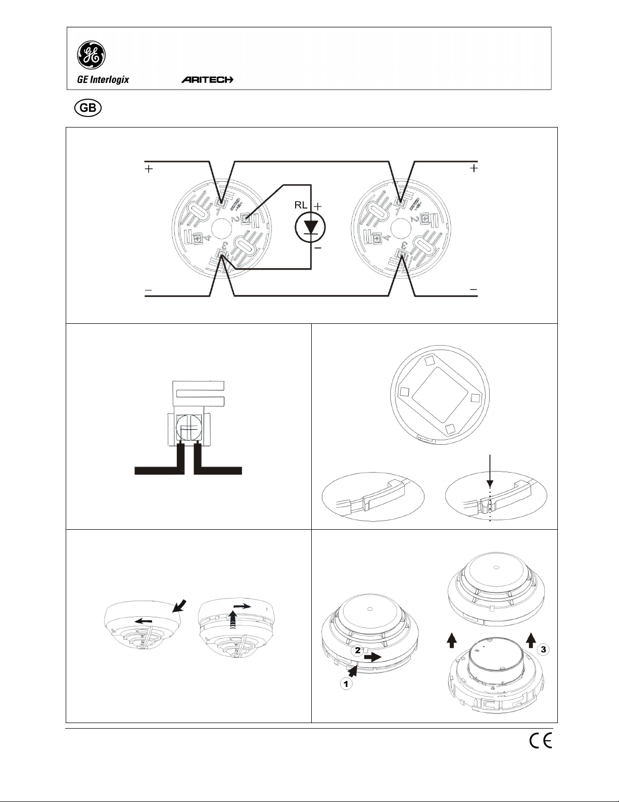
Connections
The detectors must be connected as shown in figure X. The cable
from the last detector on the loop should return to the control panel
to close the loop.
The positive line cable (+) must be connected to terminal 1, and
the negative line (-) to terminal 3. If a remote indicator is used, its
positive line cable (+) must be connected to terminal 2 in the
mounting base and the negative to terminal 3.
To connect the cables in the mounting base, remove a piece of
insulation (about 1 cm in length), pass the cables through the hole
and connect each cable in its proper location. To lock each cable,
unscrew each mounting base connection. Slide the un-insulated tip
of the cable under the metal piece and screw down (figure Y).
Check cable continuity before connecting.
Addressing
Each detector requires a numeric address between 1 and 125 for
identification purposes. The address may be set using the PG700
portable address programmer or the fire system control panel.
Consult the handset or fire panel manual for more full instructions.
Connecting the detector to the mounting base
Once the mounting base is in position, the detector is connected
by inserting it and turning. To remove the detector, turn it in the
opposite direction (figure [).
Locking catch
All of the detector heads have a locking catch to prevent
unauthorised removal.
To enable locking, the locking catch must be broken (figure Z).
After connecting the detector, it will be locked in place.
To remove a locked detector, press through the hole (figure \)
using a screwdriver or similar, and turn.
Testing
• Check that all detectors are properly assembled in their
mounting bases.
• Activate the control panel and check for correct operation.
• Check that all of the installed detectors are recognised by the
control panel. If any detector is not recognised, check that no
duplicate addresses have been assigned, check the correct
assembly of the detector and its connection.
• To test smoke detectors, apply smoke or approved aerosol
and verify alarm condition.
• To test heat detectors apply temperature using for example a
hair dryer and verify that the detector goes into alarm.
Consult the fire panel manual for further test procedures.
M
AINTEN ANCE
In normal environments cleaning should be done at least every
three or four years. It is recommended that random functional tests
be carried out every six months.
DP1551, DI1552
1. Remove the detector form the mounting base
2. Remove the detector cover by pressing the catch with a
screwdriver and turning (see figure 6)
3. Use a vacuum cleaner or clean compressed air to remove the
dust from the chamber.
4. Re-install the detector cover
5. Assemble again the detector in its mounting base and test it.
DT1553
These detectors do not require special maintenance or cleaning.
Only authorised personnel must carry out adjustments.
S
ECURITY CERTIFICATE (DI1552)
KILSEN S.A. radioactive facilities....................................IR-B/197/97
The DI1552 has been approved by Spanish Industry and Energy
Ministry, as EXEMPT from authorisation as radioactive installation.
Approval code .................................................................. NHM-D161
The detector corresponds exactly with approved sample.
Quality system........................................................ ISO9001 certified
Source manufacturer............................. Amersham International plc.
NRPB and CIEMAT laboratories measures done, (following
European Nuclear Energy Agency):
Radioactive source..................................................... Americium 241
Average activity............................... 0.33 ± 0.04 µCi (12.1 ± 1.5 kBq)
Radiation level at 0.1m......................................................0.01 µSv/h
Contamination .................................................................<0.1 Bq/cm
Valid use period is for 10 years. It is forbidden to tamper with the
workings of the unit or to remove any labels or signs. If radioactive
source is suspected of being faulty, please contact KILSEN S.A.
This certificate covers all devices with referred approval code.
2
Page 3

ECHNICAL CHARACTERISTICS
T
DI1552 DP1551 DP1551T DT1553 DB304 S700
Supply Voltage 22-38V 22-38V 22-38V 22-38V
Standby current 200 µA @ 38 V 350 µA @ 38 V 350 µA @ 38 V 250 µA @ 38 V
Alarm current < 11 mA < 11 mA < 5 mA < 11 mA
EMC Standards EN 50130-4, EN
50081-2
Operating
-10 a 60ºC -10 a 60ºC -10 a 70ºC -10 a 70ºC
EN 50130-4, EN
50081-2
EN 50130-4, EN
50081-2
EN-50130-4, EN
50081-2
temperature
Storage
-10 a 70ºC -10 a 70ºC -10 a 70ºC -10 a 80ºC
Temperature
Maximum relative
95% 95% 95% 95%
humidity
Remote indicator AI300 AI300 AI300 AI300
Dimensions 45 x Ø 99 mm 45 x Ø 99 mm 51 x Ø 99 mm 45 x Ø 99 mm Ø 103 x 23
Mounting base DB304 DB304 DB304 DB304
Accessories S700 S700 S700 S700
Terminals 4 screws, washer
Wire cross
1.5 mm²
section
Type of cable Twisted pair Twisted pair Twisted pair Twisted pair
Protection Index IP205 IP205 IP42 IP205
Coverage See EN54-14
(2001) 60-80 m²
Fixing screws Depending on the
See EN54-14
(2001) 60-80 m²
See EN54-14
(2001) 60-80 m²
See EN54-14
(2001) 60-80 m²
Depending on the
type of ceiling 2 x
type of ceiling
35 mm
Installation piping Ø 20 mm
Colour White White White White White White
Weight 116g 109g 78g 43g 23g
 Loading...