

GE Arctica PSS 23 Series, Arctica PSS 25 Series, Arctica PSS 27 Series, Arctica PSS 29 Series Technical Service Manual
Page 1
C
GE Consumer Home Services Training
TECHNICAL SERVICE GUIDE
“CustomCoolTM”
MODEL SERIES:
Arctica Side by Side
PSS 23, 25, 27,
29 Cu. Ft.
PUB # 31-9075 06/01
Page 2

IMPORTANT SAFETY NOTICE
The information in this service guide is intended for use by
individuals possessing adequate backgrounds of electrical,
electronic, and mechanical experience. Any attempt to repair a
major appliance may result in personal injury and property
damage. The manufacturer or seller cannot be responsible for the
interpretation of this information, nor can it assume any liability in
connection with its use.
WARNING
To avoid personal injury, disconnect power before servicing this
product. If electrical power is required for diagnosis or test
purposes, disconnect the power immediately after performing the
necessary checks.
RECONNECT ALL GROUNDING DEVICES
If grounding wires, screws, straps, clips, nuts, or washers used
to complete a path to ground are removed for service, they must
be returned to their original position and properly fastened.
All rights reserved. This service guide may not be reproduced in whole or in part
in any form without written permission from the General Electric Company.
GE Consumer Home Services Training
Technical Service Guide
Copyright © 2001
Page 3

Table of Contents
Introduction . . . . . . . . . . . . . . . . . . . . . . . . . . . . . . . . . . . . . . . . . . . . . . . . . . . . . . . 2
Use and Care . . . . . . . . . . . . . . . . . . . . . . . . . . . . . . . . . . . . . . . . . . . . . . . . . . . . . 3-4
Operation . . . . . . . . . . . . . . . . . . . . . . . . . . . . . . . . . . . . . . . . . . . . . . . . . . . . . . . . 5-6
Mechanical Disassembly . . . . . . . . . . . . . . . . . . . . . . . . . . . . . . . . . . . . . . . . . . . 7-8
Diagnosis Chart. . . . . . . . . . . . . . . . . . . . . . . . . . . . . . . . . . . . . . . . . . . . . . . . . . 9-10
Temperature Resistance Chart . . . . . . . . . . . . . . . . . . . . . . . . . . . . . . . . . . . . . . 11
Strip Circuits . . . . . . . . . . . . . . . . . . . . . . . . . . . . . . . . . . . . . . . . . . . . . . . . . . . . . 12
Control Board Connections . . . . . . . . . . . . . . . . . . . . . . . . . . . . . . . . . . . . . . . . . 13
Schematic Wiring Diagrams . . . . . . . . . . . . . . . . . . . . . . . . . . . . . . . . . . . . . . . . 14-15
Illustrated Parts/Exploded Views . . . . . . . . . . . . . . . . . . . . . . . . . . . . . . . . . . . 16-20
– 1 –
Page 4
Introduction
2001 Arctica SxS models are being introduced in
response to the requirement for more energy-efficient
refrigerators by mid year 2001, along with having
feature and operation enhancements.
One of the innovative features is the “CustomCool
TM
bin. The system will provide optimum rapid cooling,
(ExpressChillTM) , and safely thaw frozen foods
(ExpressThawTM).
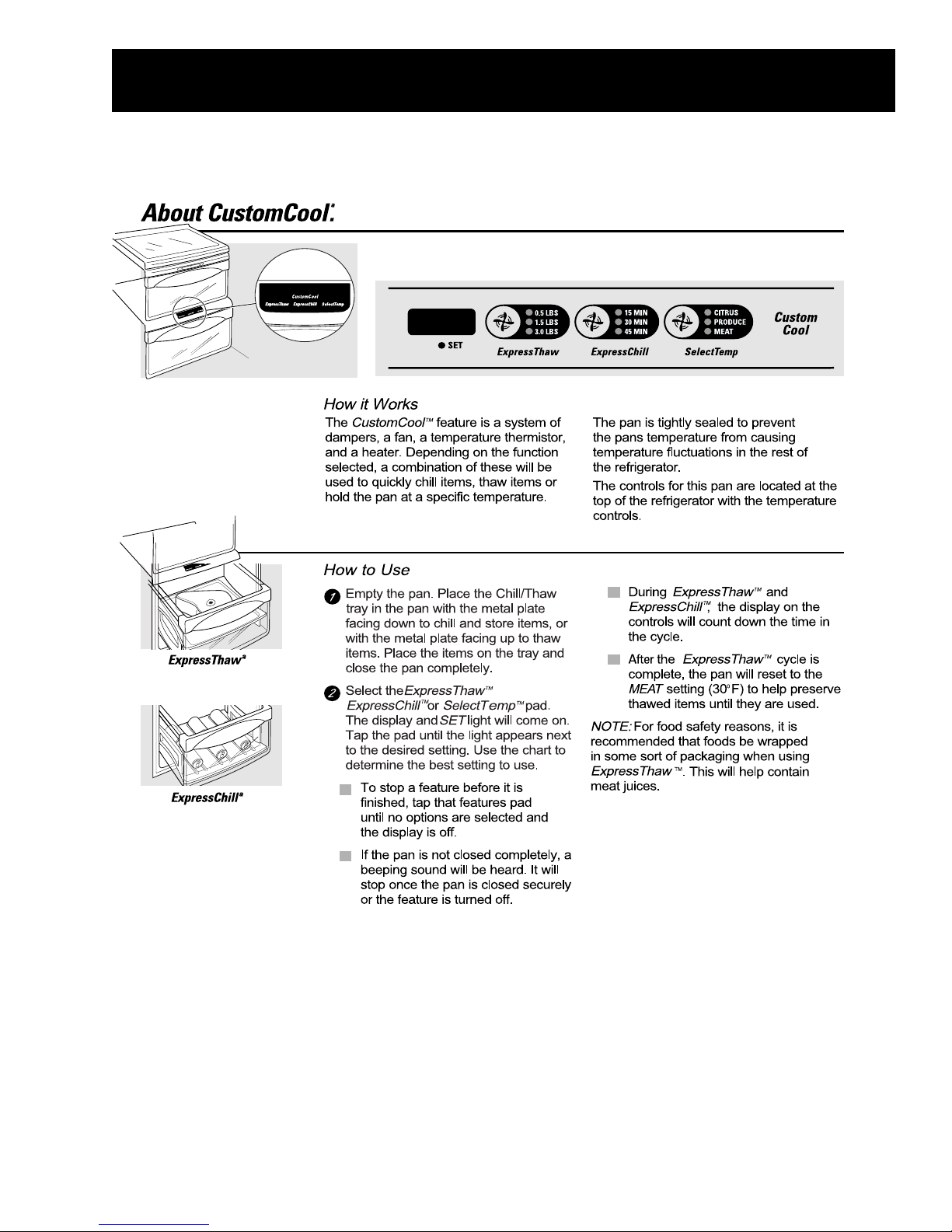
The main system components consist of two air
dampers, a DC exhaust fan, reed switch, control
board with buzzer, 3 color light diodes, a heater, and
a thermistor. These components provide feedback
to the main refrigerator processor board, and control
the temperature and air flow in the “CustomCool
TM
pan at the bottom of the fresh food compartment. A
tray, which has a metal surface on one side is
provided to place the foods on for chill or thaw.
The consumer sets the temperature from the
touchpad controls at the top of the fresh food
compartment, and selects mode of operation, and
length of cycle. Air circulates from the freezer and is
heated or maintained by the thermistor and control
settings.
The CustomCool
TM
pan is tightly sealed and has a
tray which when placed in the metal plate facing
down position, helps provide the chill, and in the metal
plate up position helps to provide thaw. It also
provides a method of catching liquid when thawing
”
and defrosting. The seals in their orginal position are
extremely important in maintaining fresh food and
feature temperatures.
”
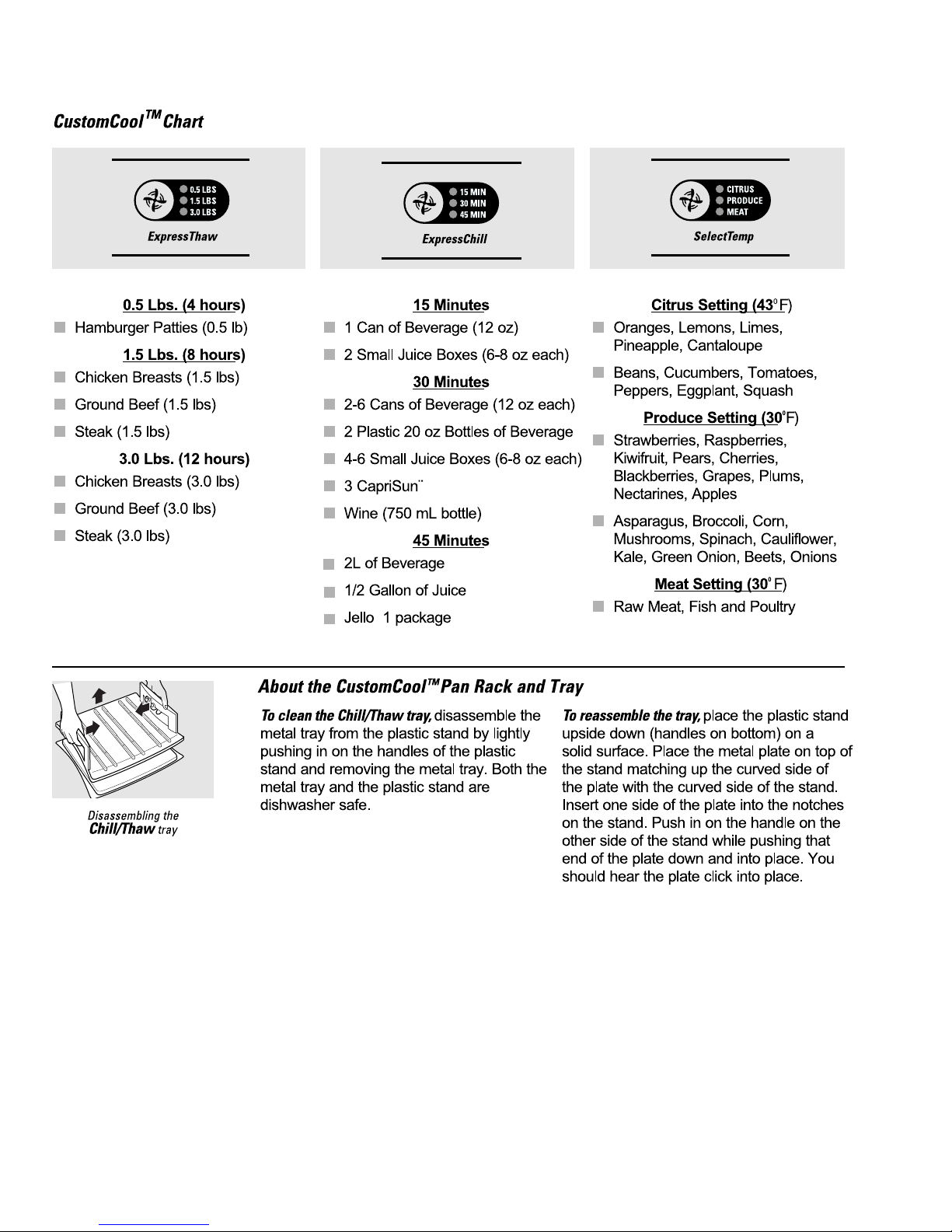
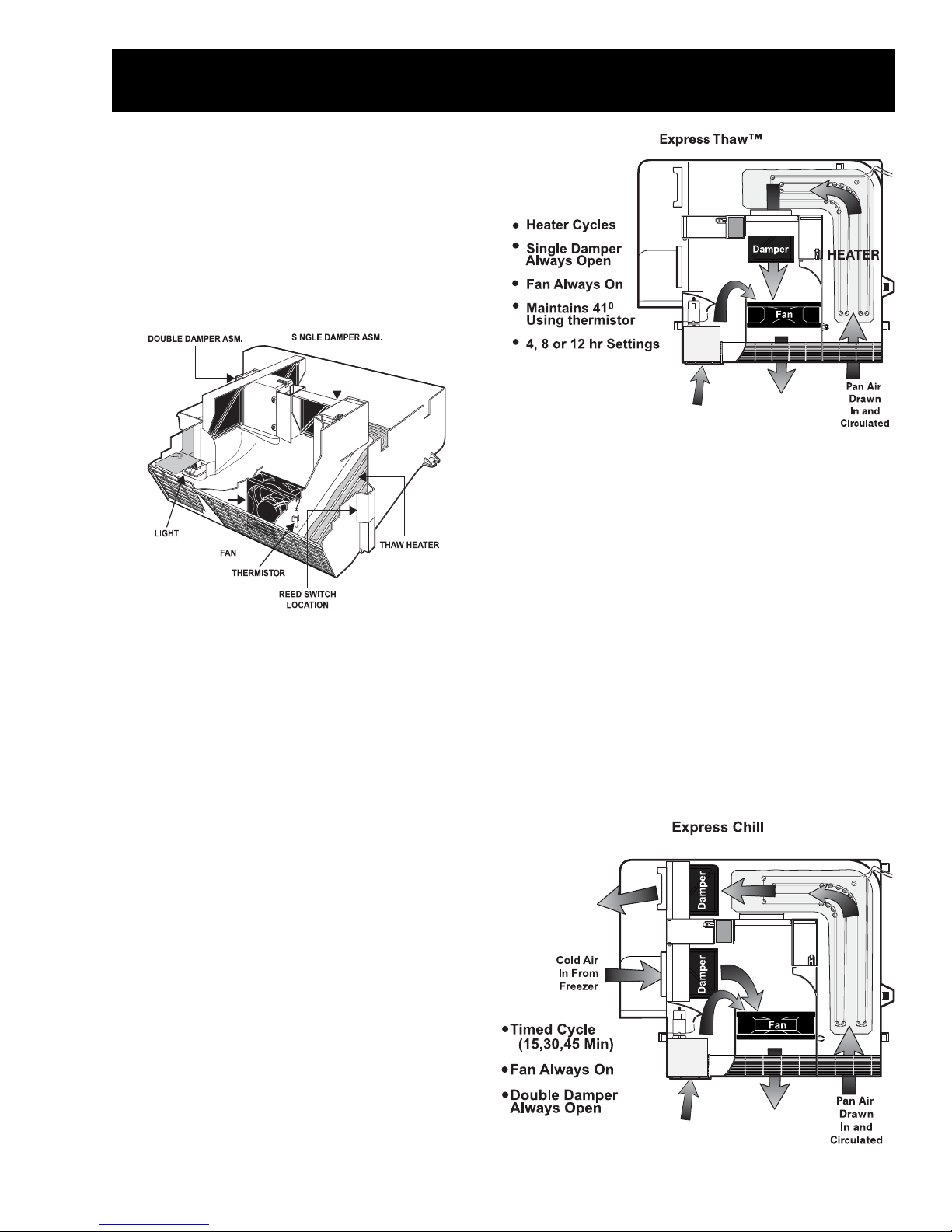
Three selection choices are provided for the
consumer:
• ExpressThaw
(maintains 41
TM
Selection in lbs.
0
)
.5 lbs.(4 hours)
1.5 lbs.(8 hours)
3.0 lbs.(12 hours)
• ExpressChill
TM
Selection in 15 minute
increments
15 Minutes
30 Minutes
45 Minutes
TM
• SelectTemp
Selection in preset
temperatures
Citrus (43
0
43
)
Produce (34
0
F) (Heater/Fan on to maintain
0
F)(Double damper open, no
fan)
Meat (30
0
F) (Double damper open, no fan)
– 2 –
Page 5
Customer Use and Care
– 3 –
Page 6
– 4 –
Page 7
Operation
Operation is initated by the consumer when the
selection is made using the touch control at the top
of the fresh food section. The user will have placed
the chill/thaw tray in the proper position, metal
plate facing down for chill, and up for thaw, and
pan closed. A reed switch is mounted on the right
side of the pan to provide a completed circuit when
the pan is tightly closed. Open reed switch
initiates a “beep” from the processor located in the
CustomCool
TM
pan assembly.
The warmed air is circulated through the pan to
satisfy the temperature setting. Response to drastic
temperature change is limited between two and ten
minutes. The main control board located in the rear
of the refrigerator will only respond to 8 degrees of
temperature change per minute as determined by
the resistance of the thermistor.
NOTE: DO NOT MANUALLY FORCE DAMPER
DOORS OPEN, IT WILL DAMAGE THE ASSEMBLY
Based on users input one of the three selections is
selected, with multiple inputs indexing to provide
TIME, WEIGHT, or TEMPERATURE and
countdown LED. One of three leds will light the
selection portion of the touchpad to provide
feedback and selection information to the user.
The signal is then sent to the main processor and
uses preset software parameters to provide DC
inputs to the CustomCoolTM processor board
mounted in the cover assembly.
When the selection is made a thermistor located in
the side of the lower cover sends temperature
information (resistance) to the main processor. The
processor software determines what combination
of dampers or heater need to be used to achieve
the desired setting. (See thermistor temp chart on
page 8).
A double door damper 12VDC operates in the
TM
ExpressChill
mode, and both sides open to allow
cold air to be drawn in and circulated within the lower
cover. The single damper door is also closed to
prevent loss of cold air and it is returned through the
other side of the diverter back to the freezer
compartment. The double door is cycled open and
shut to maintain the temperature selection selected
by the user, based on thermistor resistance
feedback to the main processor board.
TM
Airflow is directed from a diverter in the freezer
side wall to provide cold air or drawn from fresh
food compartment, and is circulated by a 12VDC
fan in the front of the lower cover. When the
thermistor is calling for warmer air the single
damper motor is energized (12VDC) to open and
the 30 watt strip heater is turned on.
– 5 –
Page 8

CustomCoolTM feature has a third temperature preset selection which is SelectTempTM. It shows on the
control panel as Citrus (43
0
F), Produce (340 F) and Meat (300 F). Note airflow, damper, and fan
operation as described below.
SelectTempTM-Citrus Setting
SelectTemp
TM
-Produce Setting
SelectTempTM-Meat Setting
NOTE: After
ExpressThaw
cycle is complete,
the pan will reset to
the MEAT setting
(300 F) to help
preserve thawed
items until they are
used.
TM
– 6 –
Page 9

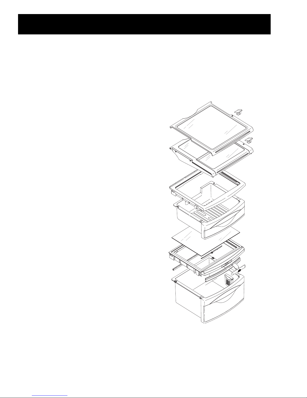
Mechanical Assembly and Disassembly
To Service complete
TM
CustomCool
pan and
Component access.
WARNING: MAKE SURE POWER IS
DISCONNECTED!
To Service Components:
st
1. Remove 1
fresh food section.
2. Lift up and out to remove the CustomCool
front chill cover (WR17X10915).
3. Remove two screws in front of CustomCool
lower cover (WR31X10006), two screws on
either side of the pan, and one screw in the
back of the housing.
and 2nd bin from bottom of
TM
7. Remove the freezer grill mullion (must be
removed prior to CustomCool
(WR02X10829) from the freezer side, by
inserting a #2 Phillips screwdriver into the
center of the diverter and turning the screw
counterclockwise. (See illustration below)
TM
TM
service),
4. Remove two screws holding chill water
reservoir assembly to back of refrigerator, and
plastic deflector cover.
5. In the freezer compartment lift up on freezer
baskets to remove (no need to remove rails),
to completely provide access to the lower air
duct cover.
6. Push in on the plastic lower freezer air tower,
and then push up to remove. It is attached by
two tabs one located on the backside of the
freezer and the other rest on the air diverter
asm.
TM
8. The CustomCool
assembly to the right to free from refrigerator
wall. A large StyrofoamTM insert is located in
the raised end of the upper cover housing,
note position for replacement, it must be
repositioned correctly to reassemble. The
upper cover can be removed, components
exposed.
9. Slots molded into the lower pan hold the fan,
single damper assembly, and dual damper
assembly. Pull up to release and push back
into slot to reassemble.
assembly is now free, slide
– 7 –
Page 10

NOTE: It is critical that all seals be replaced to
maintain proper temperatures in the
CustomCoolTM pan and in the refrigerator.
Several variations in the lighting components at
TM
the CustomCool
bin have been used in limited
numbers. You may encounter a version that has
light tubes, colored diodes on the pan PC board,
or a colored insert. Service is obvious on each
system. The terms CustomCoolTM has been
referred to as QuickChillTM on some models.
– 8 –
Page 11

Diagnostics and Problem Solving
MELBORP NOITULOS
MT
looCmotsuC
MT
wahTsserpxE
.gnikrowton
.wahtt'nseod
tcerrocerusekamotstupniremotsuckcehC.1
.tesneebsahemitdnanoitcnuf
eritnerofsruoh42deen-etadnoitallatsnikcehC.2
MT
looCmotsuCtceffalliw,ezilibatsottinu
.ecnamrofrep
sarevocpotevomerdetcennocsidrewophtiW.3
dna,slaes,kcehcdna6egapnodebircsed
MT
.nib
looCmotsuCtasnoitcennocssenrah
niegakcap-erroemitesaercnI-gnigakcaP.1
.citsalp
tceles-tcudorprofdetcelesthgiewgnorW.2
.thgiewtcerroc
.thgiewregralatceles-tnetnoctafhgihsahmetI.3
.puedislatemhtiwyartwahTehtgnisutoN.4
MT
nib
looCmotsuCfosedishtobnoslaeskcehC.5
.egakaelriarofkooldna
,rotcennocniptaecnatsiserretaehkcehC.6
.ecalpernepo,yakosetacidniecnatsiserssenrah
MT
looCmotsuCninafDCV21kcehC.7
swohstifi,
.nepowohsdluohs,ecalpersgnidaerecnatsiser
niegakcap-erroemitesaercnI-gnigakcaP.1
.citsalp
tceles-tcudorprofdetcelesthgiewgnorW.2
.thgiewtcerroc
.thgiewregralatceles-tnetnoctafhgihsahmetI.3
.nwodedislatemhtiwyartwahTehtgnisutoN.4
MT
nib
looCmotsuCfosedishtobnoslaeskcehC.5
.egakaelriarofkooldna
gnicapsreporpgnisusiremotsucerusekaM.6
.wolfriarof
MT
llihCsserpxE
.llihct'nseod
tcerrocerusekamotstupniremotsuckcehC.7
.tesneebsahemitdnanoitcnuf
eritnerofsruoh42deen-etadnoitallatsnikcehC.8
MT
looCmotsuCtceffalliw,ezilibatsottinu
.ecnamrofrep
sarevocpotevomerdetcennocsidrewophtiW.9
egapnodebircsed
7
dna,slaes,kcehcdna
MT
looCmotsuCtasnoitcennocssenrah
.nib
nepogniwohssiylbmessarepmadtahtkcehC.01
fi,)CDV21(sgnidaerecnatsiserlaminimhtiw
.repmadecalperecnatsisergniwohs
– 9 –
Page 12

MELBORP NOITULOS
.1
potst'nowgnipeeB
deertaht,desolcyllufsinaptahtkcehC
denoitisopyltcerroceratengamdnahctiws
.gnikrowdna
noitcennocssenrahkcehc,blubehtkcehC.1
krowt'nseodnapnithgiL
ecalper,esabnowercsasibluB.tekcosot
.21801X20RWhtiw
nehwysionsitifienimreteddnanetsiL.1
.gninnur
MT
looCmotsuCniysionsinaF
nap
evomer6egapnosnoitcurtsnigniwolloF.2
dnagniriwesoolrofkool,naFtaeserdna
.yrassecenfisserder
– 10 –
Page 13

Thermistor Temperature/Resistance Chart
NOTE: The thermistor’s resistance has a negative coefficient. As the temperature
increases the thermistor’s resistance decreases.
– 11 –
Page 14

Strip Circuits
– 12 –
Page 15

Control Board Connections/Location
– 13 –
Page 16

Schematic Wiring Diagram
NOTE: The feature named CustomCoolTM is
called QuickChillTM on some diagrams.
– 14 –
Page 17

NOTE: The feature named CustomCoolTM is
called QuickChillTM on some schematics.
– 15 –
Page 18

Illustrated Parts Catalog
– 16 –
Page 19

927
920
915
926
946
932
924
921
923
945
925
931
937
929
930
938
947
943
928
940
944
933
939
– 17 –
941
935
934
936
Page 20

View # Cat# Description Usage
216 WR32X10150 BUCKET EGG 1
400 WR01X10209 WHEEL PAN COVER 6
401 WRO1X10214 SCR 10-16 PL PNP 5/8 SZN 6
407 WR32X10190 PAN MIDDLE CHILL ASM 1
409 WR32X10156 GLASS PAN COVR 1
410 WR32X10151 COVER MIDDLE PAN 1
411 GFSFR02 FRESHSAVER FILTER 2PK 1
412 WR02X10684 HOLDER FRESHSAVER 1
413 WR02X10650 HUMIDITY CONTROL 1
414 WR14X10059 GASKET PAN CRV FRONT 1
417 WR021X10633 SLIDE MIDDLE PAN COVER 1
440 WWR17X10793 WINE RACK 1
470 WR32X10149 COVER TOP PAN ASM 1
471 WR32X10147 PAN ASM TOP 1
477 WR17X10921 TRAY DRIP CHILL 1
478 WR17X10922 RACK CHILL 1
487 WR32X10189 PAN ASM CHILL 1
488 WR02X10815 BOSS SPACER 1
489 WR04X10084 NAME PLATE CHILL 1
490 WR17X10914 FRAME CHILL 1
491 WR17X10915 COVER FRONT CHILL 1
492 WR14X10101 SEAL FRONT CHILL 1
493 WR02X10807 WHEEL AND RING ASM 4
– 18 –
Page 21

View # Cat# Description Usage
494 WR02X10813 MAGNETCHILL 1
495 WR14X10098 SEAL SIDES CHILL 2
496 WR14X10097 SEAL AHU CHILL 1
497 WR14X10100 SEAL FRAME & AHU 1
498 WR14X10099 SEAL REAR CHILL 2
499 WR17X10918 PLATE SEAL CHILL 1
501 WR71X10249 SHELF SLIDEOUT ASM 1
503 WR02X10818 LINKAGE PAN CHILL L.H. 1
504 WR02X10819 LINKAGE PAN CHILL R.H. 1
505 WR02X10662 STOP SHELF 3
530 WR71X10247 SHELF TUCKAWAY ASM 1
915 WR02X10829 GRILL MULLION 1
920 WR31X10008 COVER UPPER 1
921 WR31X10006 COVER LOWER 1
922 WR60X10064 FAN CHILL
1
923 WR60X10063 DAMPER ASM DESUPPLY 1
924 WR60X10062 DAMPER ASM SUPPLY 1
925 WR31X10007 PLENUM TOP 1
926 WR31X10009 DUCT CAVITY CHILL 1
927 WR14X10095 GASKET MULLION DUCT 1
928 WR31X10011 GRILL VANES CHILL 1
929 WR02X10820 COVER LED CHILL 1
930 WR51X10049 HEATER THAW 1
931 WR02X10809 RELECTOR 1
932 WR14X10096 GASKET DAMPER CHILL 1
933 WR31X10012 LIGH T SOCKET CHILL 1
– 19 –
Page 22

VIEW # Cat# Description Usage
934 WR02X10812 LAMP 40W CHILL 1
935 WR31X10010 GRILL BULB CHILL 1
936 WR14X10092 SEAL AHU CHILL 1
937 WR23X10203 HARNESS CHILL AC 1
938 WR23X10202 HARNESS CHILL AC 1
939 WR14X10090 SEAL AHU CHILL 1
940 WR23X10204 SWITCH REED CHILL 1
941 WR14X10091 SEAL AHU CHILL 1
942 WR01X10239 WASHER RETAINER CHILL 4
943 WR55X10066 BOARD ASM PAN LED 2
944 WR14X10093 GASKET LC 1
945 WR14X10094 GASKET UC 1
946 WR31X10013 NOISE WALL CHILL 1
947 WR55X10030 SENSOR TEMPERATURE 1
– 20 –
 Loading...