

Page 1

$GYHQW&RPP HUFLDO
)LUH6\VWHP
Document Number: 466-1835 Rev. C Junel 2003
Part No. 60-562-03
60-562-06
Contents
About This Manual .............................................................1
Special Installation Requirements ......................................1
UL Listed Installations ................................................1
California State Fire Marshall Listed Installations ......4
Planning the Installation .....................................................4
Panel Types ..................................................................4
Panel Components .......................................................4
Panel Terminals ..................................................................5
Panel Accessory Kit ............................................................5
BUS Device Headers ..........................................................6
Panel Devices ..............................................................6
SuperBus 2000 Touchpads .................................................6
SuperBus 2000 Modules .....................................................6
SnapCards ...........................................................................6
Installing the System ..........................................................6
Determining the Panel Location ..................................7
Running Wires to the Panel Location ..........................7
System Wire Lengths ..........................................................7
Mounting the Panel .....................................................8
Installing Optional Panel Snapcards ............................8
Connecting SuperBus 2000 Modules and Touchpads .9
SuperBus 2000 Touchpads .................................................9
SuperBus 2000 Modules ...................................................10
Voice Siren 25/70 Volt Converter Card (60-773) .............12
Connecting Detection Devices to Panel Zone Inputs 12
Connecting Speakers .................................................12
Connecting Sirens ......................................................13
Connecting Commercial Fire Devices ......................13
Installing an RJ-31X Phone Jack (13-081) ................13
Connecting the Phone Line to the Panel with a DB-8
Cord (49-442) ............................................................14
Mounting/Connecting an AC Power Transformer ....14
Installation Instructions
Installing Panel Backup Battery(s) ........................... 15
Powering Up the Panel ..................................................... 15
Programming the Panel .................................................... 15
Using the Downloader Software to Program the Panel 16
Using an Alphanumeric Touchpad to Program the Panel
16
Entering/Exiting Program Mode ...................................... 16
Using Item Numbers ........................................................ 16
Special Programming Settings .................................. 17
Partitions/General Partition Settings ......................... 17
Partitions/Alarms ...................................................... 19
Partitions/X10 .......................................................... 21
Partitions/Reporting ................................................. 21
Partitions/Arming ...................................................... 23
Partitions/Zones ....................................................... 26
Codes ................................................................................ 27
Specific Phone Number Settings .............................. 29
Advanced Settings .................................................... 31
Phone Access Settings .............................................. 33
Local Phone Settings ........................................................ 33
Remote Phone Settings ............................................. 34
Zone Settings ............................................................ 35
Tripping Hardwire Zones .......................................... 36
Tripping Learn Mode Wireless Sensors .................... 36
I/O Settings ............................................................... 39
Accessory Modules .......................................................... 40
Fixed Output Settings ............................................... 42
Alarm Settings .......................................................... 43
System Settings ................................................................ 44
Miscellaneous Settings ..................................................... 48
Remote Downloader Programming ................................. 50
Advent Downloader Programming ........................... 50
Installing Line Carrier Devices ........................................ 50
Programming the Panel House Code ........................ 50
Page 2

Installing X10 Modules ....................................................50
Adding Lights/Devices to Program Memory ............51
Testing the System ............................................................51
Basic System Commands ..........................................51
Testing Panel Backup Battery(s) ...............................51
Testing Hardwire and Wireless Zones/Sensors .........51
Menu Outputs ...................................................................74
Access Codes and Authority Level Settings ....................76
Authority Level Settings ..................................................76
Item Numbers Index and Record ......................................77
If a Wireless Sensor Fails the Zone/Sensor Test ..............52
Testing Outputs and Sirens ........................................52
Testing the X10 Modules (menu controlled outputs) 53
Testing Phone Communication .................................53
Testing Central Station Communication ...................53
Adjusting Touchpad Display Contrast ......................53
Troubleshooting ................................................................55
Appendix A:
System Configuration Worksheets ...................................63
Determining Maximum Panel Wire Length .....................64
Other System Devices ......................................................65
X-10 Module and Device Settings ...................................65
Partition/Area Descriptions ..............................................66
SuperBus 2000 Device Information .................................67
Zone and Sensor Information ...........................................68
Appendix B: Reference Tables .........................................87
Contact ID Codes and Event Types ................................102
Additional CID Reporting ..............................................105
Smoke and Heat Detector Installation ............................107
Appendix C:
Commercial Fire Wiring Examples ................................109
Connecting Speakers for Fire Protective Signaling Units
109
Connecting Horns and Strobes .......................................109
Connecting Hardwire Full Pulls .....................................109
Connecting Water Flow Detection Devices. ..................109
Wiring AL602ITI Power Supply .................................... 110
)
*(,QWHUORJL[$GYHQWDQG6XSHU%XVDUHUHJLVWHUHGWUDGHPDUNVRI*(,QWHUORJL[
$OORWKHUWUDGHPDUNVDUHSURSHUWLHVRIWKHLURZQHUV
$OOULJKWVUHVHUYHG
*(,QWHUORJL[
6HFRQG6WUHHW1RUWK
1RUWK6DLQW3DXO01
7HFKQLFDO6XSSRUW
Page 3
About This Manual
This manual provides information for planning, installing,
programming, and testing an Advent Commercial security
or fire system. When necessary, this manual refers you to
other documentation included with compatible peripherals.
“Appendix A: System Configuration Worksheets” on
page 63 are included for you to record hardware layout and
software programming settings.
About the User Guide
The User Guide contains user worksheets that should be
filled out during the installation and programming of the
system.
Special Installation Requirements
Commercial Fire Panel
The commercial fire panel can be used as a fire warning
system and an intrusion alarm system. When using the commercial fire panel as both a fire warning and intrusion alarm
system, follow the guidelines below:
All aspects of fire and burglary applications must occur in
separate partitions/areas.
All onboard panel inputs and outputs must be used only
for fire or burglary applications. Do not mix fire and burglary applications.
Bus 1 and Bus 2 headers must be used only for fire or bur-
glary applications. Do not mix fire and burglary applications on inputs and outputs of any bus device.
Some installations may require configurations dictated by
city/state codes, insurance, or Underwriter’s Laboratories
(UL). See “UL Listed Installations” for various UL component and configuration listings.
UL Listed Installations
This section describes the minimum requirements for different UL Listed installations.
Basic System
Commercial Fire (60-562-03 or 60-562-06) Control Panel
SuperBus 2000 VFD (60-804-01) or LCD (60-803-01)
Alphanumeric Touchpad
24 VAC output, 100 VA Class I, 110VAC, 60 Hz (60-830)
or 24 VAC output, 100 VA Class II, 110VAC, 60 Hz (60-
823) Line Carrier AC Power Transformer
17.2 AH or 18.0 AH Backup Battery(s) (60-781)
Backup Battery Cable Assemblies (49-475 [red] and 49-
476 [black])
UL listed 4 ohm, 15W Speaker
2K ohm EOL Resistor(s) (49-467) or (49-454)
Police Station Connected Burglary Alarm Units and Systems (UL 365)
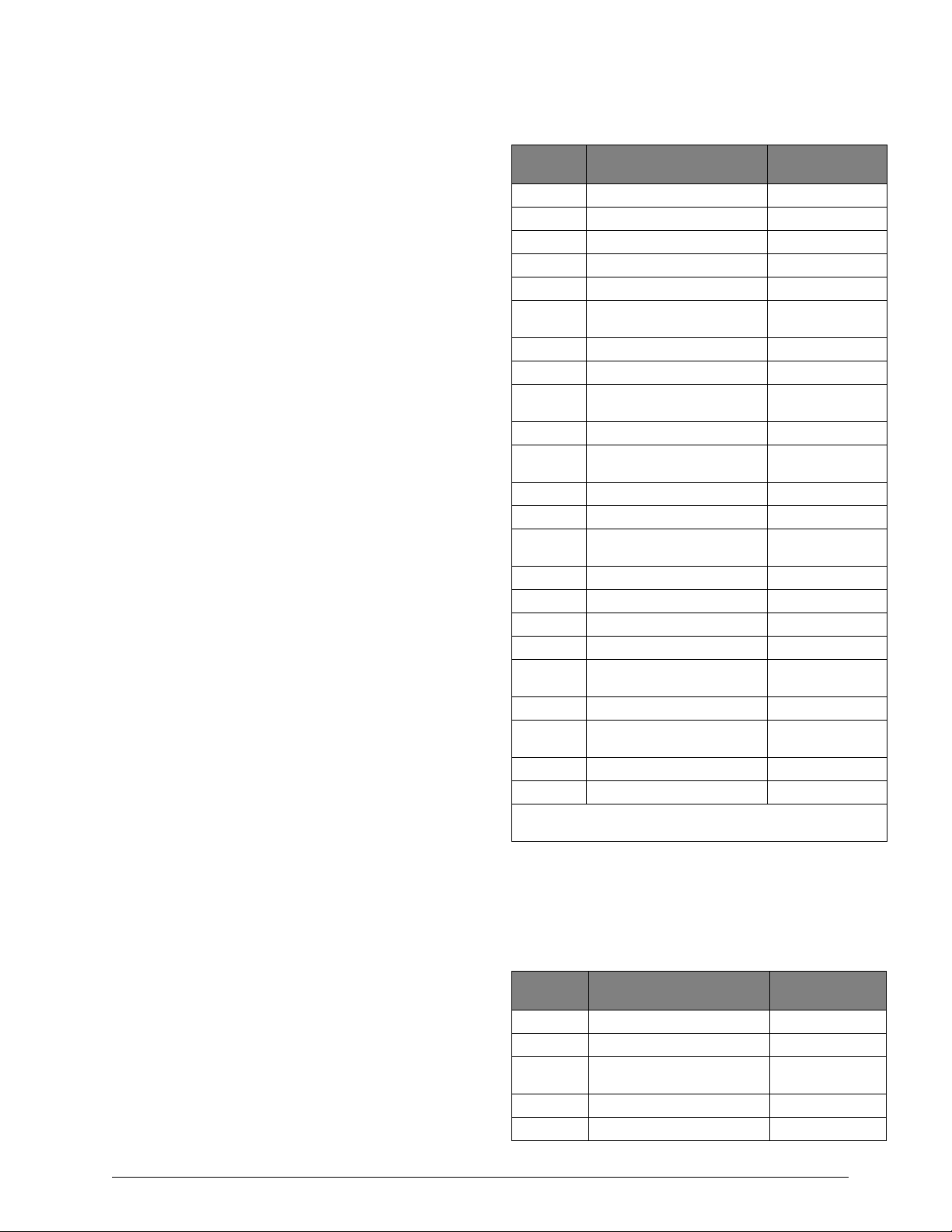
The system Feature Numbers shall be set as follows in UL
365 listed systems:
Table 1. UL 365 Listed System Settings
Feature
No.
xx002 Siren Time Out 16 min. minimum
xx003 Standard Entry Delay 45 sec. maximum
xx004 Exit Delay 60 sec. maximum
yy003 Number of Attempts 5 min. 10 maximum
yy004 Communication Format 0 Contact ID
xx088 Report Partition/Area Events
to Central Station
xx092 Enable Auto Force Arming 0-Off
xx097 Exterior Arming Verification 0-Off
xx098 Audible Verification at Close
Report
xx102 One-Time Reset Enabled 0-Off
xx108 Enable Daily Reporting of
Partition Trouble
17034 Phone Test Interval 1 Day
17036 AC Stable Time 90 sec. maximum
17041 Hours to Delay Before
Reporting AC Failure
17049 RF Supervisory Time A 4 hours
17069 No Phone Line Attached 0-Off
17072 Enable RF Jam Detect 1-On
17073 Battery Test Interval 1=4 hours
17076 Commercial or Residential
Installation
17078 Detect Receiver Failure 1-On
17079 Alarm Messages Played at
High Volume
17096 Report System Events 1-On
47004 Zone Attributes (edit zones) N/A
xx = Two digit partition number.
yy = Two digit non-pager phone number.
Local Burglar Alarm Units and Systems (UL 609)
Feature Required Setting
1-On
1-On
1-On
8 hours (or less)
1-Commercial
1-On (High)
System Setup and Programming
The system Feature Numbers shall be set as follows in UL
609 listed systems:
Table 2. UL 609 Listed System Settings
Feature
No.
xx002 Siren Time Out 16 min. minimum
yy004 Communication Format 0 Contact ID
xx088 Report Partition/Area Events
to Central Station
xx092 Enable Auto Force Arming 0-Off
xx097 Exterior Arming Verification 0-Off
Feature Required Setting
1-On
Advent Commercial Fire System
1
Page 4
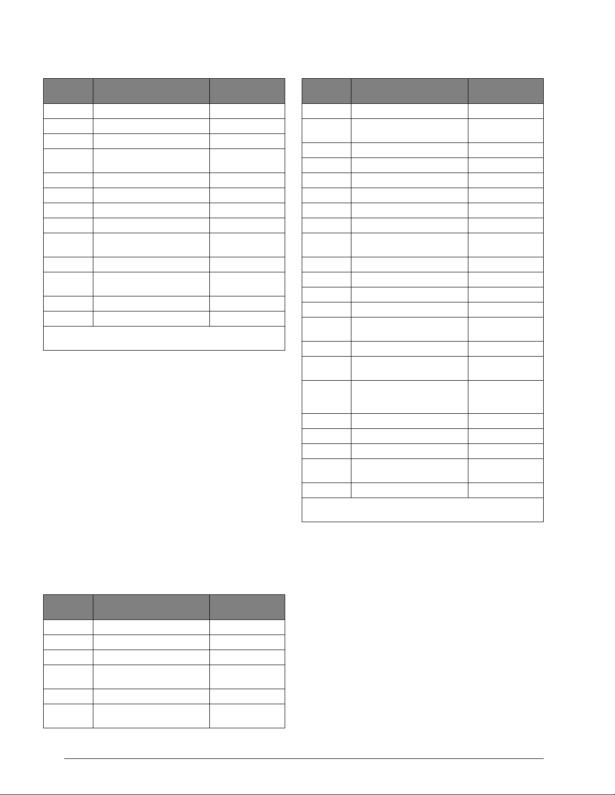
Table 2. UL 609 Listed System Settings (Continued)
Feature
No.
xx102 One-Time Reset Enabled 0-Off
17034 Phone Test Interval 1 Day
17036 AC Stable Time 90 sec. maximum
17041 Hours to Delay Before
Reporting AC Failure
17049 RF Supervisory Time A 4 hours
17069 No Phone Line Attached 0-Off
17072 Enable RF Jam Detect 1-On
17073 Battery Test Interval 1=4 hours
17076 Commercial or Residential
Installation
17078 Detect Receiver Failure 1-On
17079 Alarm Messages Played at
High Volume
17096 Report System Events 1-On
47004 Zone Attributes (edit zones) N/A
xx = Two digit partition number.
yy = Two digit non-pager phone number.
Control Units for Fire Protective Signaling Devices (UL
864)
Feature Required Setting
8 hours (or less)
1-Commercial
1-On (High)
Basic system using:
Commercial Fire (60-562-03 or 60-562-06) Control Panel
24 VAC output, 100 VA Class I, 110 VAC, 60 Hz (60-830)
Line Carrier AC Power Transformer
plus:
SuperBus 2000 Fire Alphanumeric Touchpad (60-810-04)
SuperBus 2000 Dual Phone Line Module (60-768)
UL 864 listed 4-8 ohm, 15W Speaker
Hardwire 2-Wire Smoke Detector (Compatibility Identifier
#60-562, 20 per loop maximum.):
System Sensor models 2100S, 2100TS, 2100D, 2100TD, 2400,
or 2400T added (learned) into
Zone Type 80
Sentrol models 429AT, 521B, or 521BXT added (learned) into
Zone Type 80
Table 3. UL 864 Listed System Settings
Feature
No.
xx002 Siren Time Out 6 min. minimum
yy004 Comm Format 0 Contact ID
xx081 Disable Siren 1-On
xx083 Tamper Signals from Fire
Zones are Alarms
xx085 Enable Police Panic Keys 1-On
xx086 Enable Auxiliary/Medical
Panic Keys
Feature Required Setting
0-off
1-On
Table 3. UL 864 Listed System Settings (Continued)
Feature
No.
xx087 Enable Fire Panic Keys 0-Off
xx088 Report Partition/Area Events
to Central Station
xx091 Print Partition/Area Events 1-On
xx092 Enable Auto Force Arming 0-Off
xx097 Exterior Arming Verification 0-Off
xx102 One-Time Reset Enabled 0-Off
17034 Phone Test Interval 1 Day
17036 AC Stable Time 90 sec. maximum
17041 Hours to Delay Before
Reporting AC Failure
17049 RF Supervisory Time A 4 hours
17069 No Phone Line Attached 0-Off
17072 Enable RF Jam Detect 1-On
17073 Battery Test Interval 1-4 hours
17076 Commercial or Residential
Installation
17078 Detect Receiver Failure 1-On
17079 Alarm Messages Played at
High Volume
17084 First Disarm Silences Fire
Alarmd and Second Disarm
Cancels the Alarm
17096 Report System Events 1-On
17099 Print System Events 1-On
17111 Time Fire Alarm is Silenced 30 sec. (or less)
17126 Unsilence Alarm after
Silencing Period
47004 Zone Attributes (edit zones) N/A
xx = Two digit partition number.
yy = Two digit non-pager phone number.
Feature Required Setting
1-On
8 hours (or less)
1-Commercial
1-On (High)
1-On
1-On
The basic system may also include:
SuperBus 2000 Commercial RF Transceiver (60-856-95)
for use with listed wireless signaling devices
Wireless Smoke Sensor (60-849-01-95) added (learned)
into Zone Type 80
SuperBus 2000 Printer Automation Module (60-854) for
use with a listed printer
AL602 ITI NAC Power Supply (13-522)
24V Smoke Loop SnapCard (60-767)
Universal Fire Transmitter (UFT) (60-917-95)
Zone Types 11 (Extended Entry/Exit Delay), 12 (Twice
Extended Delay), 15 (Instant Interior), 17 (Instant Interior),
18 Instant Interior), 19 (Delayed Interior), 20 (Delayed Interior), 24 (Local Instant Auxiliary), and 25 (Local Special
Chime) are not to be used as primary protection circuits in
UL 864 listed systems and are for supplementary use only.
Zone Types 27, 28, and 32 (Custom Outputs) may not be
used in UL 864 listed systems.
2
Advent Commercial Fire System
Page 5
Household Fire Warning System Units (UL 985)
Basic system, plus:
Hardwire Smoke Detector (Compatibility Identifier
60-562, 20 per loop maximum):
System Sensor models 2100S, 2100TS, 2100D,
2100TD, 2400, or 2400TH added (learned) into Zone
Type 8 0 .
Sentrol models 429AT, 521B, or 521BXT added
(learned) into Zone Type 80.
The basic system may also include:
SuperBus 2000 RF Transceiver (60-821) for use with
listed wireless signaling devices.
Wireless Smoke Sensor (60-506-319.5 or 60-848-02-95)
added (learned into Zone Type 80.
SuperBus 2000 Printer Automation Module
(60-783) for use with a listed printer.
SuperBus 2000 Dual Phone Line Module (60-768) for
expansion to primary and secondary phone line reporting.
24V Smoke Loop SnapCard (60-767).
System Setup and Programming
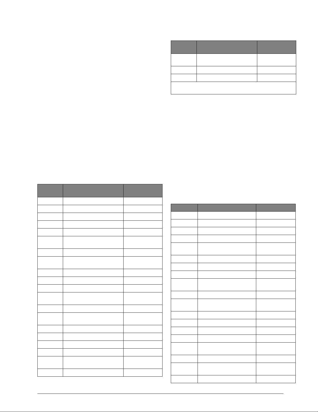
The system Feature Numbers shall be set as follows in
UL 985 listed systems:
Table 4. UL 985 Listed System Settings
Feature
No.
xx002 Siren Time Out 4 min. minimum
xx003 Standard Entry Delay 45 sec. maximum
xx004 Exit Delay 60 sec. maximum
yy004 Communication Format 0 Contact ID
xx085 Enable Police Panic Keys 1-On
xx086 Enable Auxiliary/Medical
Panic Keys
xx087 Enable Fire Panic Keys 1-On
xx088 Report Partition/Area Events
to Central Station
xx092 Enable Auto Force Arming 0-Off
xx097 Exterior Arming Verification 0-Off
xx102 One-Time Reset Enabled 0-Off
xx108 Enable Daily Reporting of
Partition Trouble
17036 AC Stable Time 90 sec. maximum
17041 Hours to Delay Before
Reporting AC Failure
17049 RF Supervisory Time A 4 hours
17069 No Phone Line Attached 0-Off
17072 Enable RF Jam Detect 1-On
17073 Battery Test Interval 1-4 hours
17076 Commercial or Residential
Installation
17078 Detect Receiver Failure 1-On
Feature Required Setting
1-On
1-On
1-On
8 hours (or less)
0-Off Residential
Table 4. UL 985 Listed System Settings (Continued)
Feature
No.
17079 Alarm Messages Play at High
Vo l u m e
17096 Report System Events 1-On
47004 Zone Attributes (edit zones) N/A
xx = Two digit partition number.
yy = Two digit non-pager phone number.
Household Burglar-Alarm System Units (UL 1023)
Feature Required Setting
1-On High
Basic system plus:
Hardwire Magnetic Contact (13-068 or 13-071)
The basic system may also include:
SuperBus 2000 RF Transceiver (60-821) for use with
listed wireless signaling devices.
Wireless Learn Mode Door/Window Sensor (60-362)
SuperBus 2000 Printer or Automation Module
(60-783) for use with a listed printer.
SuperBus 2000 Dual Phone Line Module (60-768) for
expansion to primary and secondary phone line reporting.
System Setup and Programming
The system Feature Numbers shall be set as follows in
UL 1023 listed systems:
Table 5. UL 1023 Listed System Settings
Feature No. Feature Required Setting
xx002 Siren Time Out 6 min. minimum
xx003 Standard Entry Delay 45 sec. maximum
xx004 Exit Delay 60 sec. maximum
yy004 Communication Format 0 Contact ID
xx088 Report Partition/Area Events
to Central Station
xx092 Enable Auto Force Arming 0-Off
xx097 Exterior Arming Verification 0-Off
xx102 One-Time Reset Enabled 0-Off
xx108 Enable Daily Reporting of
Partition Trouble
17036 AC Stable Time 90 sec. maximum
17041 Hours to Delay Before
Reporting AC Failure
17049 RF Supervisory Time A 4 hours
17069 No Phone Line Attached 0-Off
17072 Enable RF Jam Detect 1-On
17073 Battery Test Interval 1-4 hours
17076 Commercial or Residential
Installation
17078 Detect Receiver Failure 1-On
17079 Alarm Messages Play at High
Vo l u m e
17096 Report System Events 1-On
1-On
1-On
8 hours (or less)
0-Off Residential
1-On High
Advent Commercial Fire System
3
Page 6
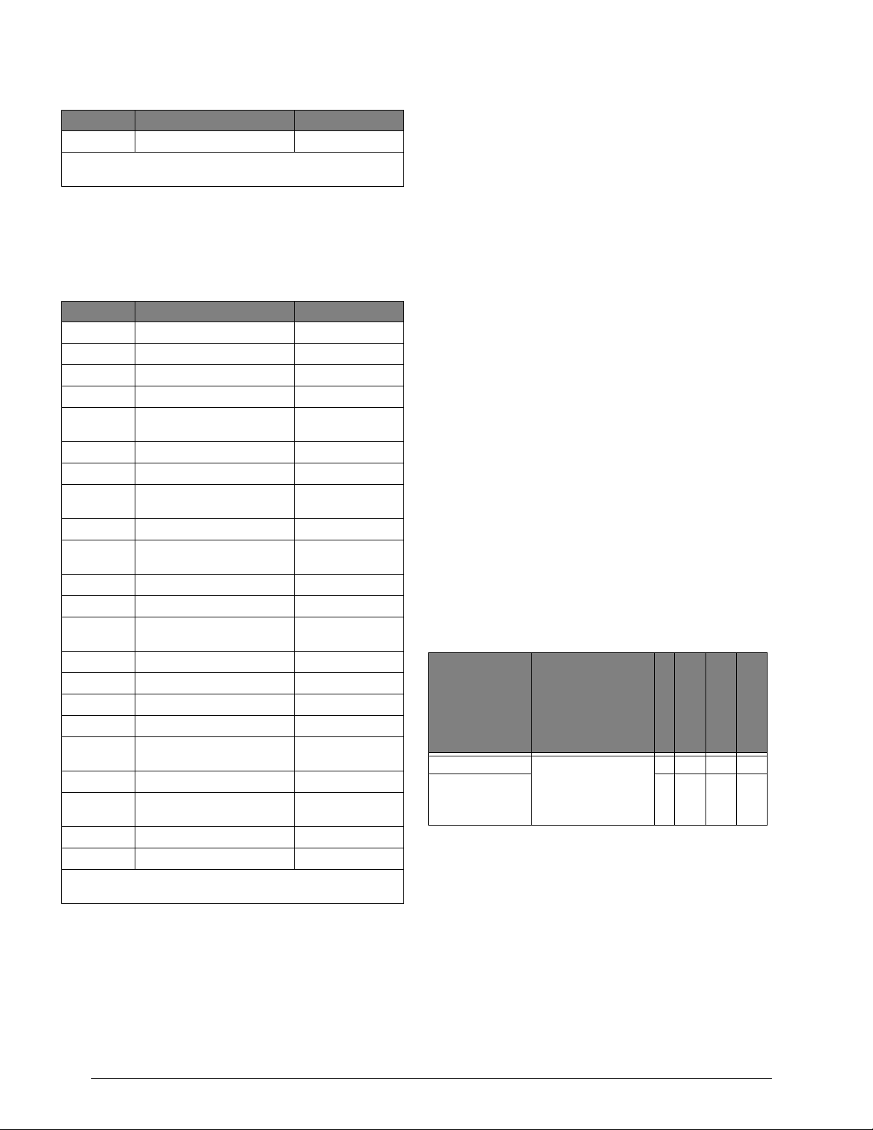
Table 5. UL 1023 Listed System Settings
Feature No. Feature Required Setting
47004 Zone Attributes (edit sensors) N/A
xx = Two digit partition number.
yy = Two digit non-pager phone number.
Central Station Burglar-Alarm System Units (UL 1610)
System Setup and Programming
The system Feature Numbers shall be set as follows in
UL 1610 listed systems:
Table 6. UL 1610 Listed System Settings
Feature No. Feature Required Setting
xx002 Siren Time Out 16 min., minimum
xx003 Standard Entry Delay 45 sec., maximum
xx004 Exit Delay 60 sec., maximum
yy004 Communication Format 0 Contact ID
xx088 Report Partition/Area Events
to Central Station
xx092 Enable Auto Force Arming 0-Off
xx097 Exterior Arming Verification 0-Off
xx098 Audible Verification at Close
Report
xx102 One-Time Reset Enabled 0-Off
xx108 Enable Daily Reporting of
Partition Trouble
17034 Phone Test Interval 1 Day
17036 AC Stable Time 90 sec. maximum
17041 Hours to Delay Before
Reporting AC Failure
17049 RF Supervisory Time A 4 hours
17069 No Phone Line Attached 0-Off
17072 Enable RF Jam Detect 1-On
17073 Battery Test Interval 1-4 hours
17076 Commercial or Residential
Installation
17078 Detect Receiver Failure 1-On
17079 Alarm Messages Play at High
Vo l u m e
17096 Report System Events 1-On
47004 Zone Attributes (edit zones) N/A
xx = Two digit partition number.
yy = Two digit non-pager phone number.
Digital Alarm Communicator System Units (UL 1635)
1-On
1-On
1-On
6-12 hours
1-Commercial
1-On High
Same as UL 1610 plus:
A UL Listed Exterior Siren
ITI CS-5000 Central Station Receiver
Sur-Gard Central Station Receiver with models
SG-DRL2A and SG-CPM2
CSA Certified Accessories
California State Fire Marshall Listed Installations
The California State Fire Marshall listing has been
approved.
ZONE ATTRIBUTES attribute 4 must be set to off
(47004)
Planning the Installation
This section describes system capabilities to help you get
familiar with the system. “Appendix A” provides planning
sheets with tables that let you record the hardware and programming configuration of the system. Fill in all necessary
information ahead of time to help prepare for the installation, and retain for your records.
Note
It is recommended that no more than 250 wireless fire
sensors (60-849-01-95 or 60-917-95 only) and a maximum of 132 of all other wireless sensors be used on 250
zone Advent systems.
If 2 Advent systems are in close proximity the total number
of wireless sensors for all systems must not exceed 250
wireless fire sensors or 132 of all other sensors.
Panel Types
To start planing the installation, find your specific panel
type below. The panel type will help determine the system
capabilities (dependent upon devices used).
Table 7. Advent Commercial Panel Types
Part Number Description
250Z, 60-562-03 Commercial Fire
132Z, 60-562-06 4 100 132 256
Panel. UL Listings
include 864, 365, 609,
985, 1023, 1610, and
1635. Red enclosure.
Users
Partitions/Areas
8 250 250 512
Panel Components
Before installing devices and making wiring connections,
familiarize yourself with the main panel components. Figure 1 shows the main component locations for the circuit
board.
LEDs
Input Zones
Central Station Reporting
The panel has been tested with the following central station
receivers using Contact ID reporting format:
4
Advent Commercial Fire System
Page 7
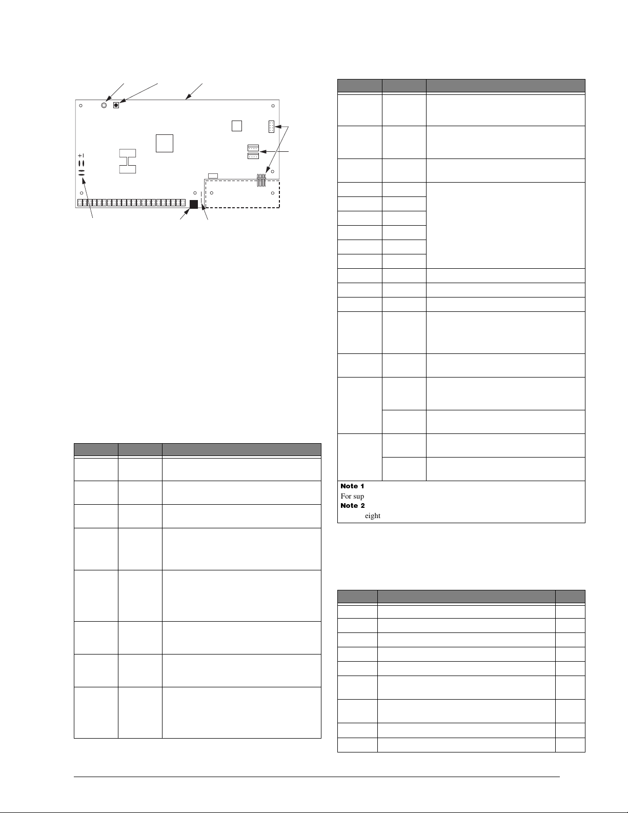
LED
MEMORY
CLEAR
BUTTON
PHONE JACK
(DB-8 CORD)
POWER
+
–
TERMINAL STRIP
BACKUP
BATTERY
LUGS
Figure 1. Circuit Board Main Components
CONTROL PANEL
CIRCUIT BOARD
OPTIONAL
EXPANSION SNAPCARD
INCOMING PHONE LINE TEST
LUGS (TIP/RING)
OPTIONAL
EXPANSION
SNAPCARD
CONNECTORS
SUPERBUS
CONNECTORS (2)
8543G05B.DSF
Panel Terminals
Table 8 describes each of the control panel terminals. Typical system wiring diagrams are provided on the last page of
this manual.
Note
A) Class 2, Class 3, and power-limited fire alarm circuits
must be installed using FPL, FPLR, FPLP, or substitute
cable permitted by the National Electrical Code ANSI/
NFPA 70. Wire that extends beyond the cable jacket must
be separated from all other conductors by a minimum of
¼-inch or by a nonconductive barrier.
OR
(B) Class 2, Class 3, and power-limited fire alarm circuit
conductors must be installed as Class 1 or higher circuits.
Table 8. Panel Terminal Strip Connections
Terminal Name Used for
1 24 VAC 24 VAC, 100 VA power transformer
connection.
2 24 VAC 24 VAC, 100 VA power transformer
connection.
3 GND Common ground connection for sirens,
general purpose outputs 1-6, etc.
4 +12 VDC Interior bell (+), and misc. DC power
supply, 12 VDC @ 5.0A maximum load
(includes Bus 1, Bus 2 headers, and
SnapCards) Current limited.
5INT
BELL
Negative (-) side of bell connection. 12
VDC @ 150mA (sink) maximum.
Positive (+) side to +12 VDC terminal 4.
Connect multiple interior bells in parallel.
See Note 1
6EXT
SIREN
Negative (-) external siren drive return
connection.
See Note 1
RTN
7EXT
SIREN
OUT
8EXT
SIREN IN
Positive (+) external siren drive output
connection. 30 VDC @ 2.5A maximum
See Note 1
load.
Positive (+) external siren drive input
connection. 30 VDC @ 2.5A or 70 VAC
@ 500 mA maximum. Normally
connected to +12 VDC terminal 4 or
other siren voltage source.
See Note 1
Table 8. Panel Terminal Strip Connections
Terminal Name Used for
9 VOICE
SIREN
10 VOICE
SIREN
11 ZONE
COM
One side of voice siren (speaker)
connection. Other side to VOICE SIREN
terminal 10.
See Note 2
One side of voice siren (speaker)
connection. Other side to VOICE SIREN
terminal 9.
See Note 2
Common return connection for general
purpose inputs 1–7, sensors, etc.
12 GPI/O 1 General purpose hardwire input. GPI/Os
13 GPI/O 2
14 GPI/O 3
15 GPI/O 4
1–6 can be programmed for use as a
hardwire contact input (2.0K ohm EOL
resistor) or a control relay driver output
(200 mA sink at 12 VDC maximum).
16 GPI/O 5
17 GPI/O 6
18 INPUT 7 Hardwire input 7.
19 Unused
20 GND Common ground
21 +SMOKE
(+12V DC
SW)
Positive (+) side of 2-wire, 12 VDC
smoke loop. (Smoke and heat sensor DC
power supply.) Switched 12 VDC @ 100
mA maximum (in alarm).
22 -SMOKE Negative (-) side of 2-wire, 12 VDC
smoke loop.
Backup
Battery 1
+RED Positive (+) side of panel backup battery
one. 12V @ 1.6A source maximum.
Source current limited.
-BLACK Negative (-) side of panel backup battery
one.
Backup
Battery 2
+RED Positive (+) side of panel backup battery
two. Source current limited.
-BLACK Negative (-) side of panel backup battery
two.
ÌiÊ£Ê
For supplementary use only.
ÌiÊÓ
Four to eight ohm maximum load between terminals 9 and 10.
Panel Accessory Kit
The components listed in Table 9 are included in the panel
accessory kit.
Table 9. Panel Accessory Kit
Part No. Description Qty.
01-022 2K-ohm, ¼-watt EOL Resistor 9
17-101 220 MF, 35 V Non-polarized Capacitor 5
31-347 Fast-On Connector for battery cables 4
40-415 Self-tapping screws for mounting modules 18
40-577 Lock and keys for panel cabinet 1
40-582 6-32 x ¼ green self-tapping screw for ground
1
connection on lower-left board
40-588 Protective adhesive pads for side-mounted
2
SnapCards
49-442 DB-8 phone cord
1
49-462 SuperBus header cable 2
Advent Commercial Fire System
5
Page 8
Table 9. Panel Accessory Kit
Part No. Description Qty.
49-467 2K-ohm EOL resistor assembly for use in UL
listed installations
49-475 Red battery cable 2
49-475 Black battery cable 2
9
BUS Device Headers
Both bus device headers allow you to use SuperBus 2000
touchpads, modules, and devices. Each header can handle
up to 31 devices for a total of 62 devices per panel. Table 10
describes the bus device headers. Use Table A.8 on
page 67 to record all SuperBus device information.
Important !
Use the SuperBus connectors (BUS 1 and BUS 2) headers for either fire or burglary applications. Do not mix fire
and burglary bus devices on either header.
All bus device inputs and outputs must be used for either
fire or burglary applications. Do not mix fire and burglary
applications on inputs and outputs of any bus device.
Table 10. BUS 1 and BUS 2 Headers
Pin Name Used for
1 (Red) +12V DC SuperBus DC power supply. 12 VDC @
2 (Green) BUS A
3 (White) BUS B
4 (Black) GND SuperBus common ground connection.
650 mA maximum. Current limited.
SuperBus communication connection.
Panel Devices
Devices that you can attach to the panel include SuperBus
2000 modules and SnapCards.
SuperBus 2000 Touchpads
The following touchpads provide complete system programming and operational control.
SuperBus 2000 2x20 LCD Touchpad: Provides system
programming and operation control. Large display shows
system messages that prompt users for information when
needed and indicates system status. (60-803-01)
SuperBus 2000 2x20 VFD Touchpad: Provides system
programming and operation control. Large fluorescent
display shows system messages that prompt users for
information when needed and indicates system status. (60804-01)
SuperBus 2000 2x20 VFD Fire Touchpad (Commercial
Fire Panels Only): Provides system programming and
operation control. Large fluorescent display shows system
messages that prompt users for information when needed
and indicates system status. (60-810-04)
SuperBus 2000 Modules
The following modules expand the system as described
below:
SuperBus 2000 Commercial RF Transceiver Module:
The transceiver enables the use of wireless zones. When
the transceiver is installed you may use a combination of
wireless and hardwire zones to reach the panel maximum.
SuperBus 2000 8Z Input Module (HIM): Provides eight
additional hardwire zone inputs.
SuperBus 2000 4-Relay Output Module (HOM): Pro-
vides four form C relay outputs that can be set up to activate other signalling devices, based on system events.
SuperBus 2000 Dual Phone Line Module: Allows for
the use of two phone lines. In the event a primary phone
line fails, a secondary line will be used.
SuperBus 2000 Printer Module: Allows you to connect
a printer to the panel.
SuperBus 2000 RS-232 Automation Module
*
: The
SuperBus 2000 RS-232 Automation module allows you to
connect an Advent panel to a compatible automation system. Once connected, the module will enable the automation system to interpret panel system status.
SuperBus 2000 LED Display Module (LED Driver
Board)*: Uses LEDs to display system and devices status.
Up to 16 SuperBus 2000 LED display or terminal boards
may be connected to one driver board.
Voice Siren 25/70 Volt Converter Card
*
: Adds high
voltage siren audio output capability to fire panels.
SnapCards
The following SnapCards expand the system as described:
8Z Input SnapCard+: Provides eight additional hardwire
zone inputs, of which two are dedicated for using 2-wire
smoke detectors.
4 Output SnapCard: Provides four form C relay outputs
that can be set up to activate other signalling devices,
based on system events, schedules, or direct control.
4Z Input/2 Output Combo SnapCard
+
: Provides three
hardwire zone inputs, one two wire smoke detector loop,
and two outputs that can be set up to activate other signalling devices, based on system events, schedules, or direct
control.
24V Smoke Loop SnapCard: Adds 24 volt, 2-wire
smoke detector capability to the panel.
Note
If the 24V Smoke Loop SnapCard is used, the panel and
snapcard 2-wire smoke loops are not compatible with the
Sentrol (ESL) 429AT smoke detector.
Installing the System
This section describes how to install the system control
panel. Before starting the installation, plan your system layout and programming using the worksheets provided in
“Appendix A” on page 63.
Installing the system consists of the following:
Determining the Panel Location
Running Wires to the Panel Location
System Wire Lengths
Mounting the Panel (page 8)
Installing Optional SnapCards (page 8)
Connecting SuperBus 2000 Modules and Touchpads
(page 9)
Connecting Detection Devices to Panel Zone Inputs
(page 12)
*) Not investigated by UL.
+) Residential use only.
6
Advent Commercial Fire System
Page 9
Connecting Speakers (page 12)
Connecting Sirens (page 13)
Connecting Commercial Fire Devices (page 13)
Installing an RJ-31X Phone Jack (page 13)
Connecting the Phone Line to the Panel with a DB-8 Cord
(page 14)
Mounting/Connecting an AC Power Transformer
(page 14)
Installing the Backup Battery(s) (page 15)
Powering Up the Panel (page 15)
Determining the Panel Location
Before permanently mounting the panel, determine the
panel location using the following guidelines:
Centrally locate the panel in relation to detection devices
whenever possible to help reduce wire run lengths and
labor.
Avoid running wires parallel with electrical wiring, or fix-
tures such as fluorescent lighting, to prevent wire runs
from picking up electrical noise.
Locate the panel where the temperature will not exceed
120°F (49°C) or fall below 32°F (0°C).
If optional wireless transceiver module is used, avoid
locations near excessive metal such as HVAC ducts, foil
wallpaper, gas/water pipes, and electrical wiring.
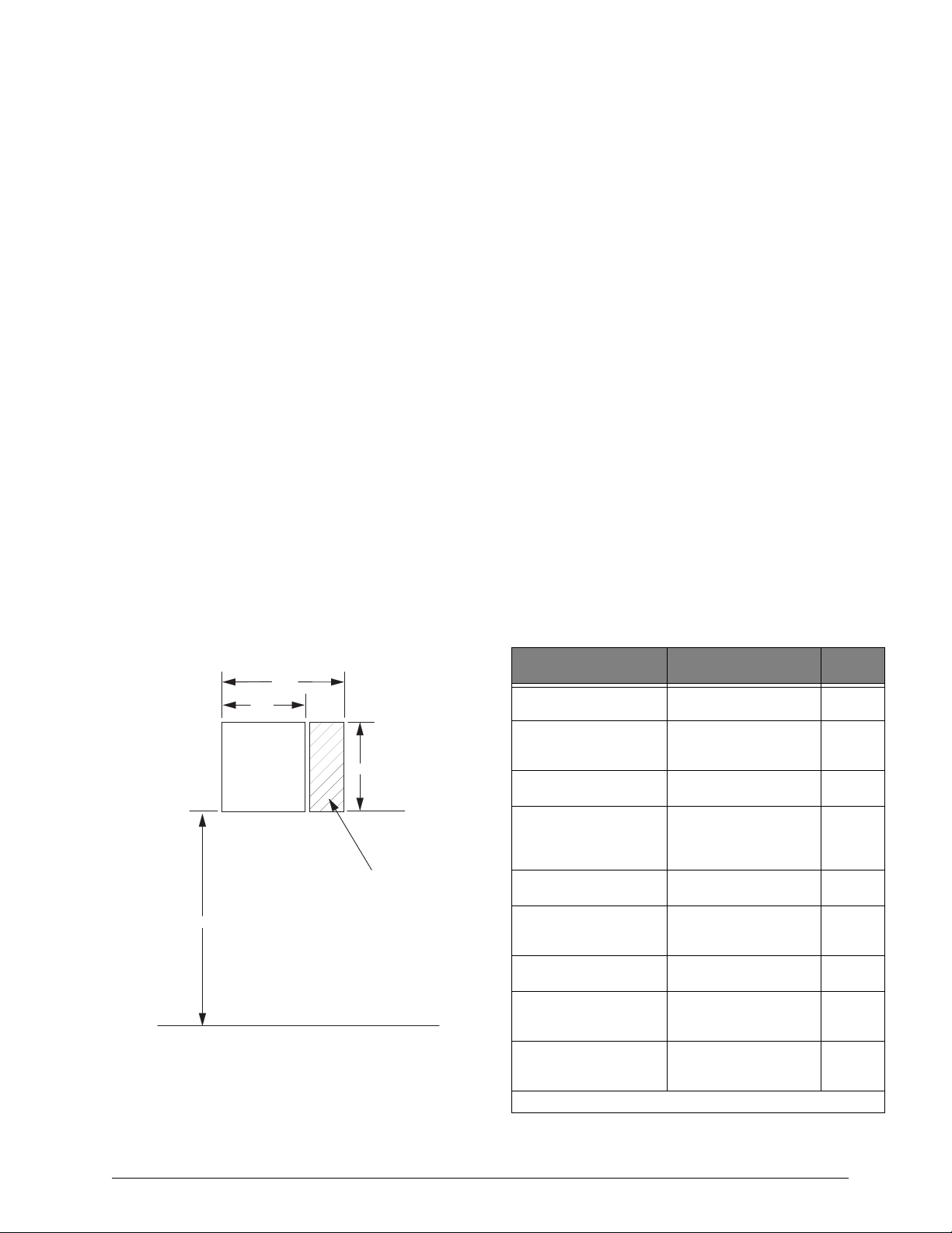
Mount the panel at a comfortable working height (about
45 to 55 inches from the floor to the bottom of the panel,
as shown in Figure 2).
Allow 6.5-inches to the right (or left) of the panel for
wiring, phone jack, and optional module mounting.
Allow at least 24-inches in front of the panel for access to
panel components.
21.5"
15"
PANEL
45-55"
NOTE
ALLOW AT LEAST 24"
IN FRONT OF PANEL
FOR ACCESS TO PANEL
COMPONENTS
FLOOR
Figure 2. Determining Panel Location
21.5"
PHONE JACK AND
OPTIONAL MODULE
MOUNTING AREA
8543G06B.DS4
Running Wires to the Panel Location
Once you have determined the best possible panel location,
run any necessary wires for the:
Power transformer
Phone line(s)
Sirens/speakers
SuperBus 2000 alphanumeric touchpads
Hardwired zones
Output devices
Optional SuperBus 2000 modules (such as
Dual Phone Line, Printer Modules, etc.)
System Wire Lengths
The total system wire length allowed varies depending on
devices powered by the panel, the wire length between
devices and the panel, and the combined wire length of all
devices.
Table 11 describes wiring recommendations for various
panel components.
For devices where no recommended wire lengths are
stated, or several devices share the same wire runs to the
panel, please see Table A.2 on page 64 to determine wire
lengths based on current draw and resistance.
Use 18-gauge wire for all commercial installations.
Listed auxiliary power supplies may be used to reach the
4000ft maximum wire length. Please see Table A.2
page 64 to determine wire lengths based on the module(s)
used.
Table 11. Wire Recommendations
Device
AC Power Transformer 2-conductor, 18-gauge
Earth Ground Single conductor, 14-
Telephone Phone grade, 22-gauge Solid or
Detection Devices 2- or 4-conductor, 22-
Output Devices 18-gauge, 500 feet
2-Wire Smoke Detectors 25-ohms per zone
Sirens, Piezos, and
Speakers
SuperBus 2000 2x20
LCD Alphanumeric
Touchpad
SuperBus 2000 2x20
VFD Alphanumeric
Touchpad
*) Not investigated by UL.
Max. Wire Length to
Panel
(located in cabinet)
gauge, 25 feet
maximum
gauge, 50-ohms
resistance per zone
including device
maximum
(including detection
device resistance)
2-conductor, 18-gauge,
500 feet maximum
22 ga.—500 ft.
18 ga.—1300 ft.
22 ga.—500 ft.
18 ga.—1300 ft.
Wire
Type
Solid or
Stranded
Solid or
Stranded
Stranded
Solid or
Stranded
Solid or
Stranded
Solid or
Stranded
Solid or
Stranded
Solid or
Stranded
Solid or
Stranded
Advent Commercial Fire System
7
Page 10
&$87,21
Table 11. Wire Recommendations (Continued)
Device
SuperBus 2000
Commercial RF
Max. Wire Length to
Panel
22 ga.—1250 ft.
18 ga.—3000 ft.
Wire
Type
Solid or
Stranded
Transceiver
SuperBus 2000 8Z Input
Module
SuperBus 2000 4-Relay
Output Module
SuperBus 2000 Dual
Phone Line Module
SuperBus 2000 Printer
Module
SuperBus 2000 RS 232
Automation Module
SuperBus 2000 LED
Driver Board
*
4 Input/2 Output
22 ga.—1750 ft.
18 ga.—4000 ft.
22 ga.—200 ft.
18 ga.—500 ft.
22 ga.—350 ft.
18 ga.—900 ft.
22 ga.—1500 ft.
18 ga.—4000 ft.
22 ga.—1500 ft.
*
18 ga.—4000 ft.
22 ga.—75 ft.
18 ga.—200 ft.
N/A N/A
Solid or
Stranded
Solid or
Stranded
Solid or
Stranded
Solid or
Stranded
Solid or
Stranded
Solid or
Stranded
SnapCard
8Z Hardwire Zone
N/A N/A
Expander SnapCard
4 Output SnapCard N/A N/A
*) Not investigated by UL.
Mounting the Panel
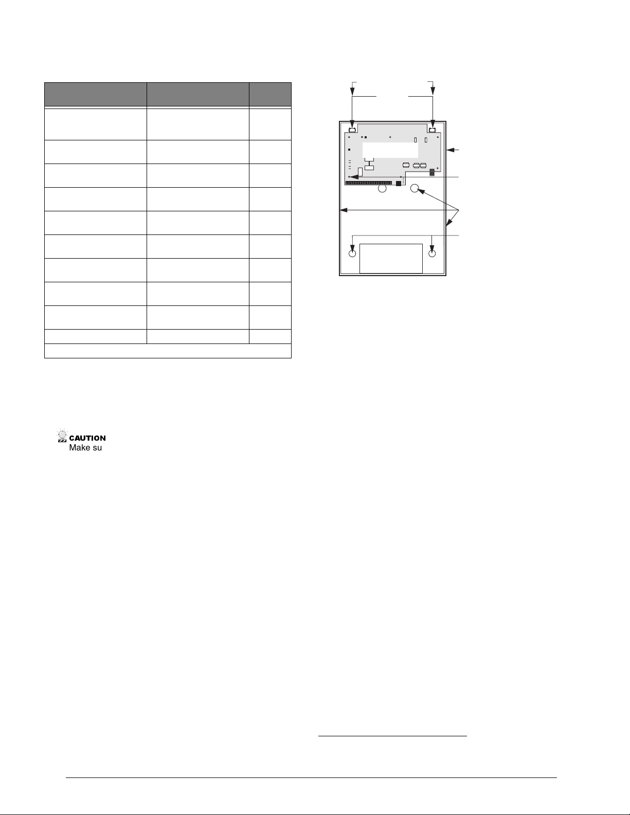
Use the following procedure to mount the panel to the wall
or wall studs using the supplied mounting hardware and the
panel mounting holes shown in Figure 3.
Make sure you are free of static electricity whenever you
work on the panel with the cover open. To discharge any
static, first touch the metal panel chassis, then stay in
contact with the chassis when touching the circuit board.
Using an approved grounding strap is recommended.
1. Open the panel door and remove the panel circuit board, accessory kit, and packing material.
2. Carefully remove the circuit board from the packing and put it in a safe static free location.
3. Remove the desired panel wiring knockouts.
4. Mount the optional key lock (if used) into the panel door.
5. Place the enclosure in position against the wall. Make sure enclosure is level and mark the locations of the two mounting holes and two keyhole mounting holes. Remember to leave room near the enclosure for any optional modules.
6. Use the appropriate mounting anchors and screws for your application. Partially insert screws into the two anchors at the two top keyhole locations, and then hang the panel chassis on the two screws.
7. Recheck level, insert the two lower screws, and then tighten all four mounting screws.
8. Route all wires to the panel.
9. Install the panel circuit board, using the five supplied board mounting screws.
S T U D S 1 6 " O N C E N T E R
K E Y H O L E
M O U N T I N G
H O L E S
C O N T R O L P A N E L
C I R C U I T B O A R D
+
+
-
B A C K U P
B A T T E R Y ( s )
Figure 3. Mounting the Panel and Circuit Board
Installing Optional Panel Snapcards
8Z Input SnapCard (60-757)
M O U N T T O S T U D S O R
I N S T A L L 3 / 4 " P L Y W O O D
M O U N T E D T O S T U D S ,
T H E N H A N G P A N E L O N
P L Y W O O D
C O N T R O L
P A N E L
E N C L O S U R E
( D O O R O P E N )
E A R T H G R O U N D
C H A S S I S S C R E W
( G R E E N )
W I R I N G
K N O C K O U T S
M O U N T I N G
H O L E S
8 5 4 3 G 0 7 B . D S F
*
4 Output SnapCard (60-758)
4Z Input/2 Output Combo SnapCard (60-756)
+
24V Smoke Loop SnapCard (60-767)
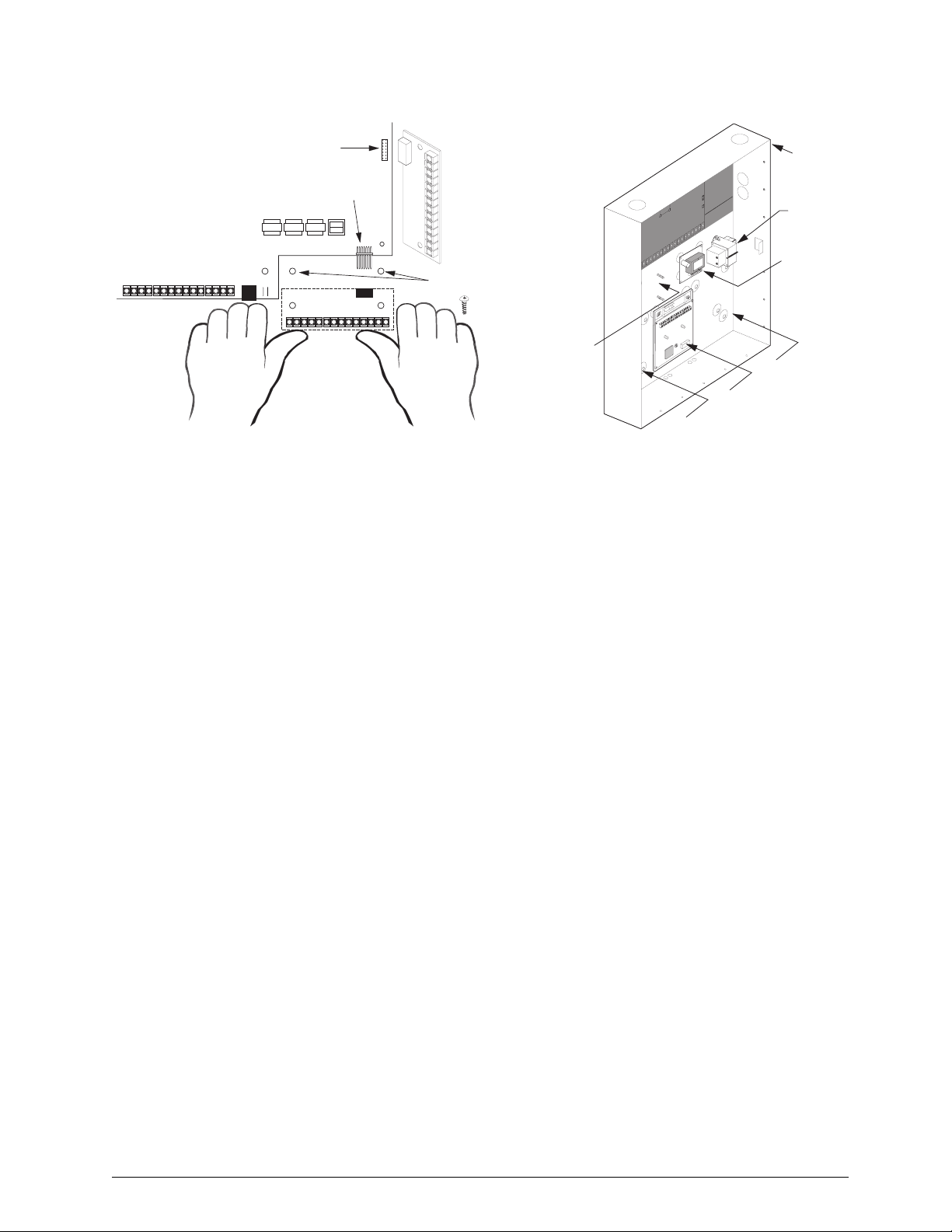
The SnapCard Connectors shown in Figure 4 allow for the
installation of two expansion SnapCards.
Carefully install a SnapCard onto the desired SnapCard
Connector and secure it in place with the two screws
included with the card.
Note
If installing 24V Smoke Loop SnapCard in the primary
expansion card connector slot, you will not be able to use
the panel cabinet knockouts behind and to the right of the
card. Whenever possible install this card into the secondary expansion card connector slot.
*) For Residential Use Only.
8
Advent Commercial Fire System
Page 11
)
D
SECONDARY EXPANSION
2
CARD CONNECTOR
PRIMARY EXPANSION
CARD CONNECTOR
CONTROL PANEL
CIRCUIT BOARD
ALIGN BOAR
HOLES WITH
STANDOFFS
EXPANSION CARD
(2
8543G86B.DSF
Figure 4. Installing an Expansion SnapCard into one of
the two SnapCard Connectors
Connect all necessary input and/or output wiring using the
Installation Instructions included with the SnapCard(s).
Note
Once the 24V Smoke Loop SnapCard is installed, the
panel onboard smoke loop becomes a 24V smoke loop
(panel terminals 21 and 22).
If the 24V Smoke Loop SnapCard is used, the panel and
snapcard 2-wire smoke loops are not compatible with the
Sentrol (ESL) 429AT smoke detector.
Connecting SuperBus 2000 Modules and Touchpads
Up to 31 SuperBus 2000 devices (combinations of touchpads and modules) can be used on each of the two SuperBus
connectors for a total of up to 62 devices. These modules
connect to the panel via a 4-wire digital data bus and may
be located inside, next to, or away from the panel cabinet
(see Figure 5). The panel cabinet may accommodate up to:
3 SuperBus 2000 HIM/HOM modules,
1 Voice Siren 25/70 Volt Converter Card,
and 2 AC Power Transformers.
To wire SuperBus 2000 devices to the SuperBus connectors
you must use the Panel SuperBus Wiring Harnesses (49-
462) included with the accessory kit. You must splice all
SuperBus 2000 module and touchpad wiring to the wires on
these harnesses. Both SuperBus connectors are the same,
and any combination of SuperBus devices (up to 31) may
be wired to either connector. When all of the SuperBus
2000 devices are wired, plug each wiring harness into a
SuperBus connector.
Note
The +12 VDC (RED) lead on the SuperBus wiring harness
is current limited to 650 mA. If the total current draw for all
devices on either SuperBus connector exceeds 650 mA,
another power source must be used—such as Terminal 4
(+12V) or an external + 12V power supply.
.
PANEL CA BINET
(COVER NOT SHOWN)
MOUNTED
TRANSFORMER
MOUNTED
VOICE SIREN 25/70
VOLT CONVERTER CARD
SPACE FOR
ND TRANSFORMER
HIM/HOM/DUAL PHONE LINE MODULE
8543264A.DSF
SPACE FOR 3RD
SPACE FOR 2ND HIM/HOM/ DUAL
PHONE LINE MODUL E
MOUNTED HIM/HOM/DUA L
PHONE LINE MODUL E
Figure 5. Mounting Devices in Panel Cabinet
Important !
Use the SuperBus connectors (BUS 1 and BUS 2) headers for either fire or burglary applications. Do not mix fire
and burglary bus devices on either header. All bus device
inputs and outputs must be used for either fire or burglary
applications. Do not mix fire and burglary applications on
inputs and outputs of any bus device.
SuperBus 2000 Touchpads
2x20 LCD Alphanumeric Touchpad (60-803-01)
2x20 VFD Alphanumeric Touchpad (60-804-01)
2x20 VFD Fire Alphanumeric Touchpad (60-810-04)
(Commercial Fire Panels Only)
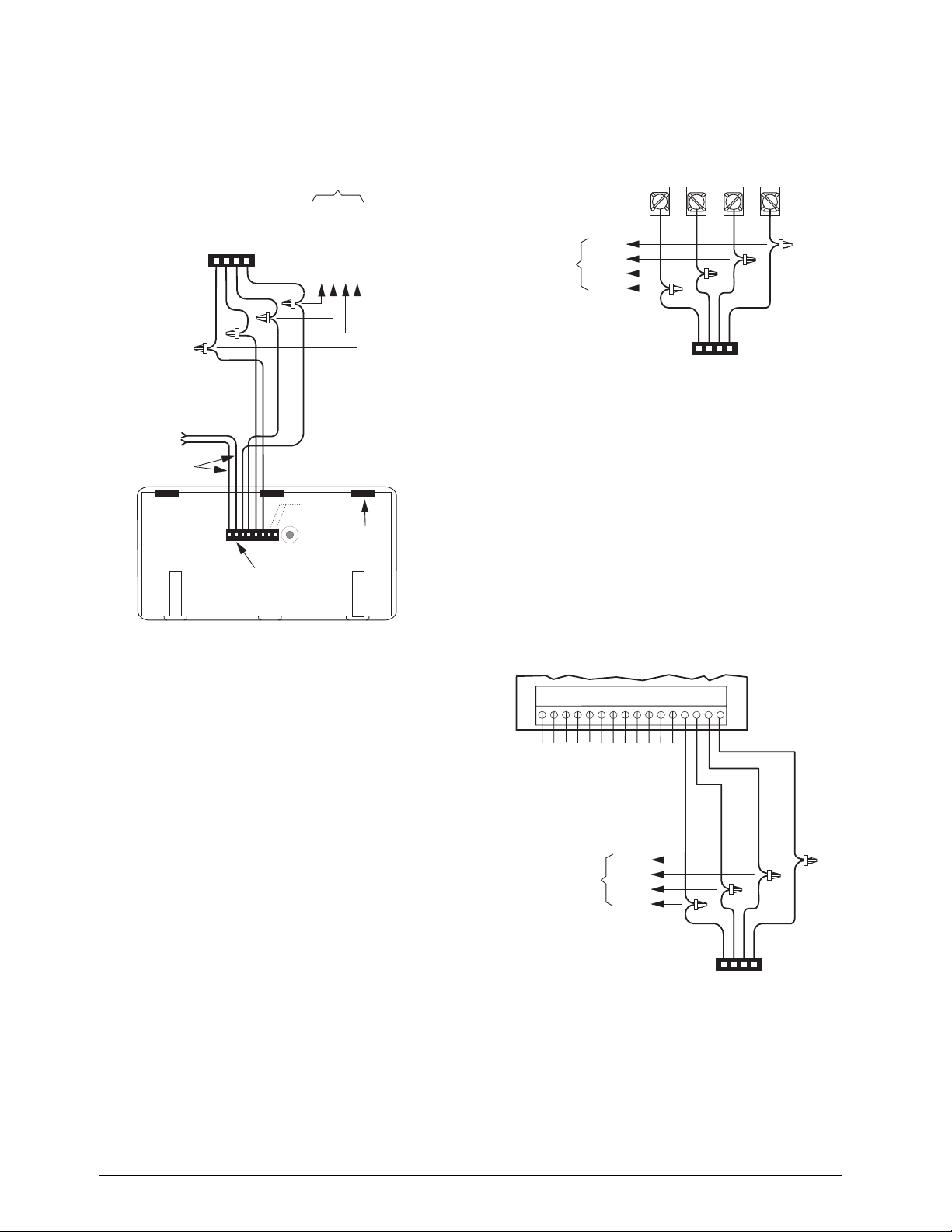
Connect SuperBus 2000 touchpads to the desired SuperBus
connector as shown in Figure 6. For mounting instructions
please see the specific touchpad Installation Instructions.
Advent Commercial Fire System
9
Page 12
8543265A.DSF
NOT
USED
YELLOW
TOUCHPAD
WIRING HARNESS
49-430
SPLICE
PANEL SUPERBUS
WIRING
HARNESS 49-462
BLACK (GND)
WHITE (BUS B)
GREEN (BUS A)
RED (+12 VDC)
TO ADDITIONAL
SUPERBUS
TOUCHPADS
AND/OR
MODULES
TAB
SLOT (3)
WIRES FOR HARDWIRE
INPUT OR KEYSWITCH
(SEE SPECIFIC TOUCHPAD
INSTALL INSTRUCTIONS
FOR INFORMATION AND
RESTRICTIONS)
F
SUPERBUS COMMERCIAL
RF TRANSCEIVER
MODULE
BUS
+12
VDC
BUS
A
B
GND
Figure 6. Connecting SuperBus 2000 Alphanumeric
touchpads
SuperBus 2000 Modules
Commercial RF Transceiver Module
Commercial RF Transceiver Module in Plastic Case
(60-821-95)
Commercial RF Transceiver Module in Metal Case
(60-856-95)
Note
For Commercial Fire installations the Commercial Transceiver Module in the Metal Case (60-856-95) must be
used.
Connect the transceiver to the panel as shown in Figure 7.
TO OTHER
SUPERBUS
DEVICES
BLACK
WHITE
GREEN
RED
PANEL SUPERBUS
WIRING
HARNESS 49-462
SPLICE
8674G05A.DS
Figure 7. Connecting SuperBus 2000 Commercial RF
Transceiver module
8Z Input Module (60-774)
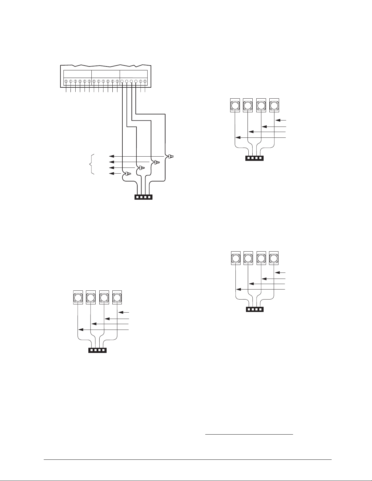
Connect the SuperBus 2000 8Z Input Module to the panel
as shown in Figure 8. Connect all necessary input wiring
using the Installation Instructions included with the module.
Important !
For proper UL 864 compliance, all 8 inputs (terminals 1
through 12) shall be one of the following:
1. Security intrusion connections or,
2. fire device connections.
Combining security and fire connections on these terminals is not approved for UL 864 by the manufacturer.
12345678910111213141516
ZONE 1
ZONE COMMON
ZONE 2
ZONE 3
ZONE 4
ZONE 5
ZONE COMMON
ZONE COMMON
ZONE 6
ZONE 7
ZONE COMMON
ZONE 8
TO OTHER
SUPERBUS
DEVICES
BLACK
WHITE
GREEN
RED
SPLICE
10
PANEL SUPERBUS
WIRING
HARNESS 49-462
8543266A.DSF
Figure 8. Connecting a SuperBus 2000 8Z Input
Module
4-Relay Output Module (60-770)
Connect the SuperBus 2000 4-Relay Output Module to the
panel as shown in Figure 9. Connect all necessary output
Advent Commercial Fire System
Page 13
wiring using the Installation Instructions included with the
module.
Connect the SuperBus 2000 Printer Module to the panel as
shown in Figure 11. Connect all other printer wiring using
the Installation Instructions included with the module.
SPLICE
8543267A.DSF
18
ZONE 1
ZONE COM
1 2 3 4 5 6 7 8 9 101112 1314 151617
NO 1
NC 1
COM 1
TO OTHER
SUPERBUS
DEVICES
NC 2
NO 2
COM 2
NC 3
COM 3
BLACK
WHITE
GREEN
NO 3
NO 4
NC 4
COM 4
RED
PANEL SUPERBUS
WIRING
HARNESS 49-462
Figure 9. Connecting a 4-Relay Output Module
Dual Phone Line Module (60-768)
Connect the SuperBus 2000 Dual Phone Line Module to the
panel as shown in Figure 10. Connect all other phone wiring
using the Installation Instructions included with the module.
SUPERBUS DUAL PHONE LINE MODULE
+12
VDC
1
TERMINAL STRIP
BUS
BUS
B
A
3
2
GND
4
SUPERBUS PRINTER
INTERFACE MODULE
TERMINAL STRIP
BUS
BUS
+12
VDC
1
PANEL SUPERBUS
WIRING HARNESS 49-462
B
A
2
GND
4
3
BLACK (GND)
WHITE (BUS B)
GREEN (BUS A)
RED (+12 VDC)
8543110A.DSF
Figure 11.Connecting a SuperBus 2000 Printer Module
RS-232 Automation Module* (60-783-02)
Connect the SuperBus 2000 RS-232 Automation Module to
the panel as shown in Figure 12. For all other connections
please see the module Installation Instructions.
S U P E R B U S 2 0 0 0
A U T O M A T I O N M O D U L E
T E R M I N A L S T R I P
B U S
B U S
G N D
B
A
4
3
2
B L A C K ( G N D )
W H I T E ( B U S B )
G R E E N ( B U S A )
R E D ( + 1 2 V D C )
V D C
+ 1 2
1
BLACK (GND)
WHITE (BUS B)
GREEN (BUS A)
RED (+12 VDC)
PANEL SUPERBUS
WIRING HARNESS 49-462
8844G05A.DSF
Figure 10.Connecting a SuperBus 2000 Dual Phone
Line Module
Printer Module
Printer Module in Plastic Case (60-783)
Printer Module in Metal Case (60-854)
Note
For Commercial Fire installations the Printer Module in the
Metal Case (60-854) must be used.
Advent Commercial Fire System
P A N E L S U P E R B U S
W I R I N G H A R N E S S 4 9 - 4 6 2
8 8 4 5 G 1 0 A . D S F
Figure 12.Connecting a RS-232 Automation Module
LED Module (Driver Board)* (60-870)
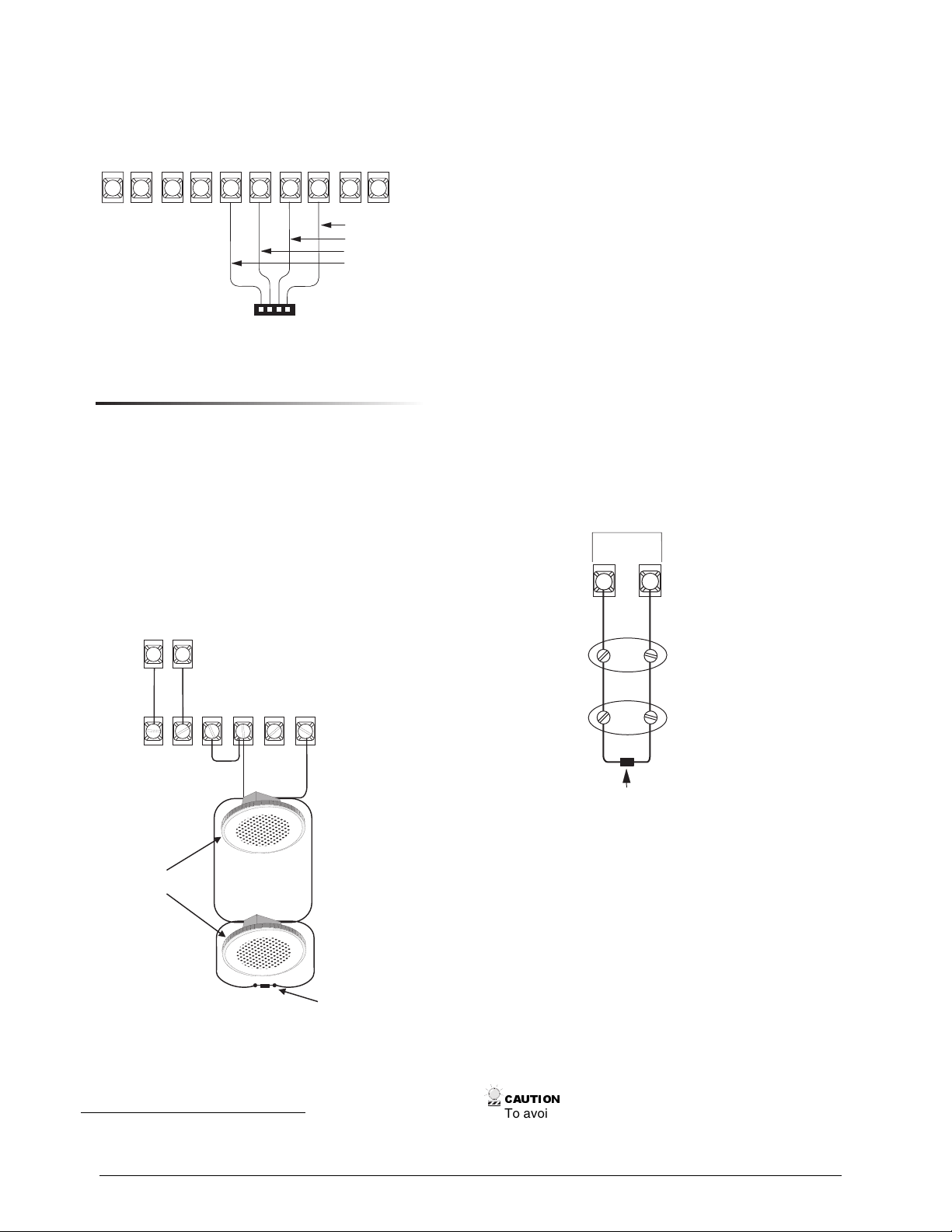
Connect the LED driver board to the panel as shown in Figure 13. For programming instructions please see “Program
LED Module” on page 41. For information on connecting
display and terminal boards please see the module Installa-
tion Instructions.
*) Not investigated by UL.
11
Page 14
DRIVER BOARD
)
U
2-W I R E
TERMINAL STRIP
CLOCK
LOAD
DATA IN
DRIVE
1
DRIVE
2
DRIVE
3
DATA OUT
RETURN
4
BUS B
BUS A
+12V
6
5
PANEL SUPERBUS
WIRING HARNESS 49-462
GND
ZONE 1
BLACK (GND)
WHITE (BUS B)
GREEN (BUS A
RED (+12 VDC)
COM
10987
Figure 13.Connecting an LED Module (Driver Board)
Voice Siren 25/70 Volt Converter Card (60-773)
Mount the card in the panel cabinet in the area shown in
Figure 5, and as described in the specific Installation
Instructions. Wire the card to the panel and speakers as
shown in Figure 14.
Note
70 volt wiring and supervision is shown. For 25 volt wiring,
connect speakers to COMMON and 25V terminals, then
jump +SUPERVISION to 25V terminal.
PANEL
TERMINALS
VOICE
VOICE
SIREN
SIREN
9
10
VOICE SIREN CONVERTER
CARD TERMINALS
+
4 OHMS
+
SUPER-
VISION
-
COM-
MON
25V70V
Connecting Detection Devices to Panel Zone Inputs
Important !
Use onboard panel inputs and outputs for all fire applications only. Do not mix fire and burglary circuits.
Connecting 2-Wire Smoke Detectors
Panel terminals 21 and 22 are set up to accept the following
12 VDC 2-wire smoke detectors.
System Sensor models 2100S, 2100TS, 2100D, 2100TD,
2400, or 2400TH.
Sentrol (ESL) models 429AT, 521B, or 521BXT
Panel terminals 21 and 22 can handle up to 20 smoke detectors with 120 uA maximum idle current per detector. Maximum total loop current in alarm condition is 100 mA.
*
Connect one or more 2-wire smoke detectors to the panel as
shown in Figure 15.
Note
If the 24V Smoke Loop SnapCard is used, the panel and
snapcard 2-wire smoke loops are not compatible with the
Sentrol (ESL) 429AT smoke detector.
S M O K E L O O P
+ 1 2 V
+
S W
+
2 1
2 2
L I S T E D 2 - W I R E ,
S M O K E / H E A T
1 2 V
+
+
+
D E T E C T O R
( U S E I N - A N D - O U T
[ D A I S Y - C H A I N ]
M U L T I P L E D E V I C E
W I R I N G M E T H O D S
O N L Y . )
2 . 0 K O H M
E O L R E S I S T O R
4 9 - 4 6 7 o r 4 9 - 4 5 4
( I N S T A L L A T L A S T D E V I C E )
L-LISTED SPEAKERS
(PARALLEL)
+ O R 2 4 V D C W I T H 2 4 V S M O K E L O O P
E X P A N S I O N S N A P C A R D I N S T A L L E D .
Figure 15.Connecting 2-Wire Smoke Detectors
Connecting Speakers
2K OHM 5 WATT
EOL RESISTOR
ASSEMBLY 49-482
9715g03d.dsf
Figure 14.Connecting the Voice Siren 25/70 Volt
Converter Card
(LOCATE AT
LAST DEVICE)
Note
Separate in and out conductors must be used at each
speaker. Do not loop a single wire around each terminal.
*) Not investigated by UL.
12
The panel provides one speaker driver output for intrusion
(steady), fire (temporal 3), and auxiliary (on-off-on-off)
alarm sounds.
The output can drive a single 8-ohm speaker or multiple
speaker circuit of 4- to 8-ohms (as shown in the following
speaker wiring diagrams). Comparable speakers are
described below and on the following page.
&$87,21
To avoid damage the panel speaker output, do not make
speaker connections with the panel powered up.
Advent Commercial Fire System
Page 15
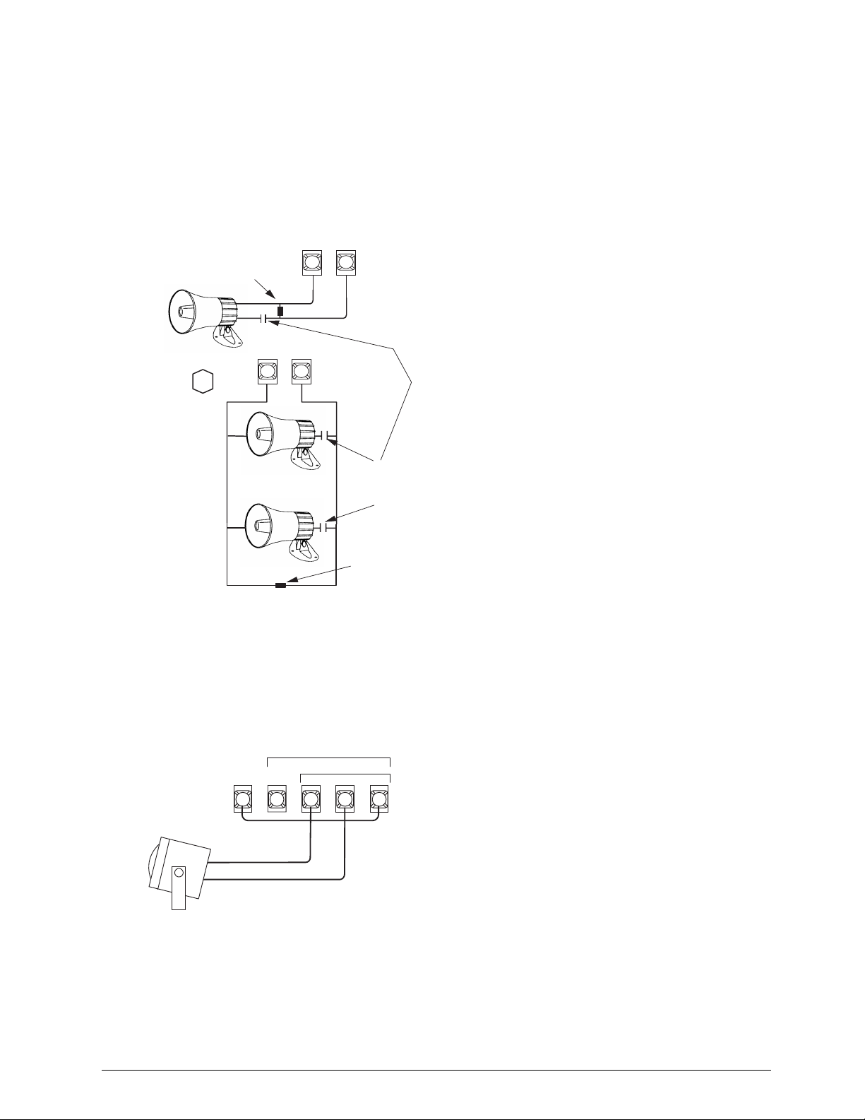
UL Listed Speaker
Use a UL listed 4-8 ohm, 30 watt speaker for siren applications such as status and a voice alarm annunciation speaker
for voice. When wiring multiple speakers, the total
impedange must be between 4 and 8 ohms. Connect the
speaker(s) to the panel as shown in Figure 16. For mounting
instructions please refer to the Installation Instructions
included with the speaker.
P a n e l T e r m i n a l S t r i p s
V o i c e
V o i c e
S i r e n
9
P a n e l T e r m i n a l S t r i p s
1 0
S i r e n
1 0
2 2 0 M F , 3 5 V
C a p a c i t o r
( N o n - P o l a r i z e d )
1 7 - 1 0 1
( L o c a t e d a t D e v i c e )
2 . 0 K O H M
E O L R E S I S T O R
4 9 - 4 6 7
( L O C A T E A T
L A S T D E V I C E )
L i s t e d 8 O H M S p e a k e r
( 3 0 W A T T )
2 . 0 K O H M
E O L R E S I S T O R
4 9 - 4 6 7
( L O C A T E A T
L A S T D E V I C E )
O R
T w o L i s t e d 8 O H M S p e a k e r s
i n P a r a l l e l ( 4 O H M S )
V o i c e
S i r e n
V o i c e
S i r e n
9
Figure 16.Connecting 15- and 30-Watt Interior
Speakers
Connecting Sirens
Connect a exterior siren to the panel as shown in Figure 17.
Note
This siren is for supplementary use only.
FOR SUPPLEMENTARY USE ONLY
EXT. SIREN/HORN
INT.
+12
BELL
PANEL TERMINALS
BLACK
RED
VDC
4 5
RTN
OUT
IN
6
7 8
Installing an RJ-31X Phone Jack (13-081)
Use the following guidelines when installing an RJ-31X
phone jack for system control by phone and central station
monitoring.
Locate the RJ-31X jack (CA-38A in Canada) no further
than five feet from the panel.
The panel must be connected to a standard analog (loop-
start) phone line, that provides around 48 volts DC (onhook or idle).
Note
The panel cannot be used on a digital or PBX phone line.
These systems are designed for digital type devices only,
operating anywhere from 5 volts DC and up. The panel
uses an analog modem and does not have a digital converter, adapter, or interface to operate through such systems.
For full line seizure, install an RJ-31X phone jack on the
premises phone line so the panel is ahead of all phones
and other devices on the line. This allows the panel to take
control of the phone line when an alarm occurs, even if the
phone is in use or off-hook.
If an analog line is not available, contact your customer’s
telecommunications specialist and tell him/her you need
an analog line off the phone switch (PBX mainframe) or a
1FB (standard business line).
Note
Connecting the panel to an analog line off the phone
switch places the panel ahead of the phone system, pre-
venting panel access from phones on the premises. However, the panel can still be accessed from off-site phones.
To connect a phone line to the panel using an RJ-31X/CA-38A jack:
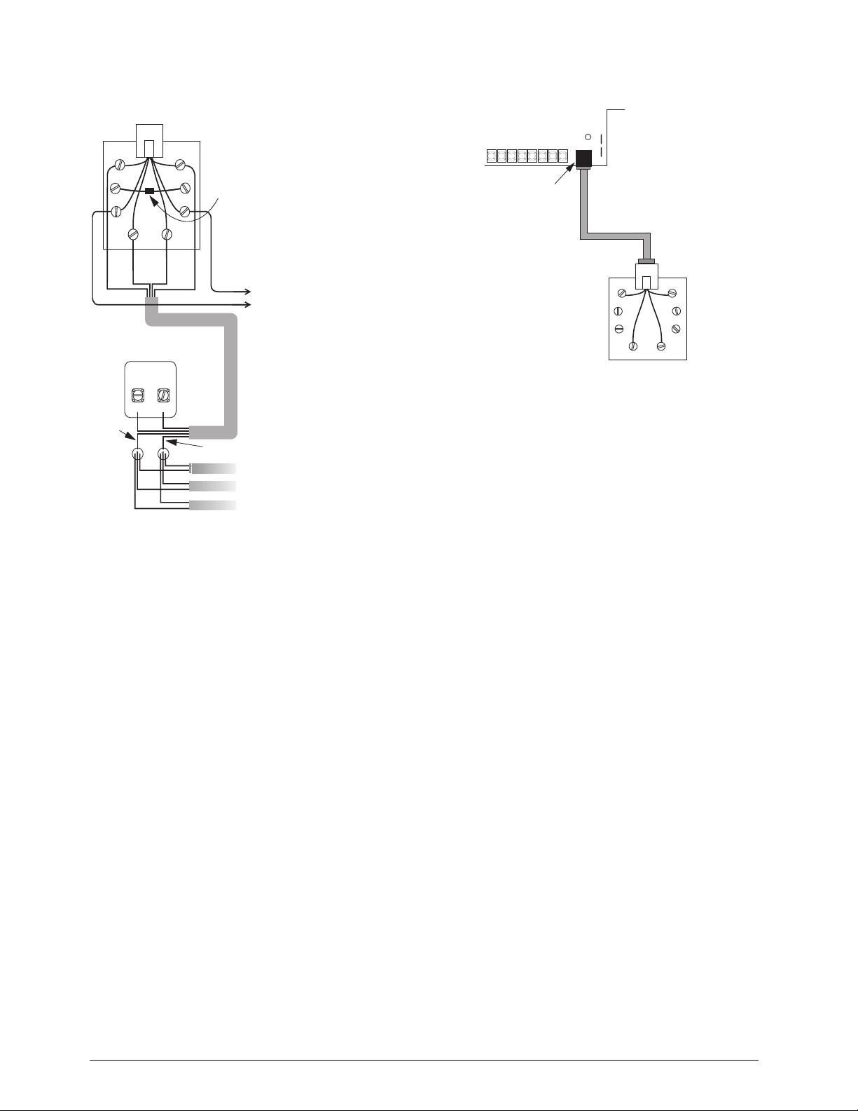
1. Run a 4-conductor cable from the TELCO protector block to the jack location (see Figure 18).
2. Connect one end of the cable to the jack.
3. At the TELCO protector block, remove the premises phone lines (lines from phone jacks on premises) from the block and splice them to the black and white (or yellow) wires of the 4-conductor cable.
4. Connect the green and red wires from the 4-conductor
cable to the A (+) and B (-) posts on the block (see Figure 18).
5. If desired, add phone jack tamper by splicing the black and yellow phone jack wires to the panel terminals and adding a 2.0K ohm EOL resistor between the blue and orange phone jack terminals as shown in Figure 18.
6. Check the phones on the premises for dial tone and the ability to dial out and make phone calls. If phones do not work correctly, check all wiring and correct where necessary. Proceed to “Troubleshooting” on page 55 if problems persist.
HARDWIRE
EXTERIOR SIREN
Figure 17.Connecting the Hardwire Exterior siren to
the panel.
8543139B.DSF
Connecting Commercial Fire Devices
For information on connecting commercial fire devices
please see Appendix C on page 109.
Advent Commercial Fire System
13
Page 16
R J - 3 1 X
)
( C A - 3 8 A )
P H O N E J A C K
(PANEL CIRCUIT BOARD)
B R N
B L U
G R N
B L K
P R O T E C T O R
G R N R E D
B L A C K
G R N ( C )
( A )
G R N
T E L C O
B L O C K
( B )
G R Y
O R G
B L KY E L
R E D
R E D
R E D ( D )
P H O N E
S P L I C E
2 . 0 K O H M
E O L R E S I S T O R
4 9 - 4 6 7 o r 4 9 - 4 5 4
( F O R
O P T I O N A L
J A C K
T A M P E R )
Y E L
W H T /
W I R E
W H I T E O R Y E L L O W
P R E M I S E S
T O P A N E L T E R M I N A L 1 1
T O P A N E L T E R M I N A L 1 2
( O R T O A N Y G E N E R A L P U R P O S E
I / O T E R M I N A L P R O G R A M M E D A S A N
I N P U T F O R O P T I O N A L J A C K T A M P E R
T O
P H O N E S
Figure 18.Installing an RJ-31X Phone Jack
Connecting the Phone Line to the Panel with a DB-8 Cord (49-442)
After installing the RJ-31X jack, you are ready to connect
the phone line to the panel.
To connect the DB-8 cord to the panel terminals and RJ31X jack:
1. Insert one end of the DB-8 cord plug into the RJ-31X (see Figure 19).
2. Insert the other end of the DB-8 cord plug into the
phone jack on the Advent panel circuit board (see Figure 19).
3. Check the phones on the premises for dial tone and the ability to dial out and make phone calls. If phones do not work correctly, check all wiring and correct where necessary. Proceed to “Troubleshooting” on page 55 if problems persist.
PHONE JACK
DB-8 CORD
PLUG
BRN
GRN RED
RJ-31X
JACK
GRY
8543268A.DSF
Figure 19.Connecting the DB-8 Cord to the Panel and
RJ-31X Jack
Mounting/Connecting an AC Power Transformer
Use the following AC power transformer with Advent Fire
panels:
24 VAC output, 100 VA Class I, 110VAC, 60 Hz (60-830)
24 VAC output, 100 VA Class II, 110VAC, 60 Hz (60-823)
Line Carrier AC Power Transformer
Note
For UL 864 Advent Fire panel installations the 24 VAC,
100 VA Class I AC transformer is required.
1. Mount the transformer in the cabinet at one of the two locations shown in Figure 5.
Note
Transformer load (secondary) terminals must face the
center of the enclosure.
2. Secure the transformer to the cabinet using the threaded standoffs and supplied hex nuts.
3. Route the AC power transformer cord or wires through one of the knockouts.
Note
The AC supply is non-power limited. It must be separated
from all power limited wiring in the cabinet by at least 0.25”
and wired using a separate knockout.
14
Advent Commercial Fire System
Page 17
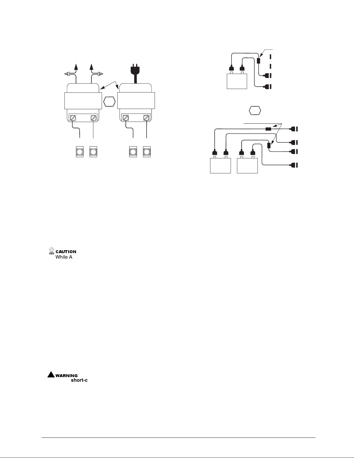
4. Wire the AC power transformer to the panel as shown
F
in Figure 20.
TO 110 VAC 60 HZ
CIRCUIT
SPLICE
LINE
CLASS 1
24 VAC 100 VA
60-830
LOAD
24
24
VAC
VAC
1
2
PANEL TERMINALS
Figure 20.Wiring an AC Power Transformer to the
Panel
TO 110 VAC 60 HZ
BUILT-IN
CIRCUIT
BREAKERS
OR
OUTLET
LINE
CLASS 2
24 VAC 100 VA
60-823
LOAD
24
VAC
1 2
8543269A.DS
VAC
24
Installing Panel Backup Battery(s)
The panel uses from one to three rechargeable, sealed 12V
lead-acid backup batteries (60-781).
Note
When replacing batteries, always replace with the same
battery type and size.
To install (or replace) backup battery(s):
1. Make sure the panel AC power is off or disconnected.
&$87,21
While AC power is applied to the panel, the charging
voltage is present at the battery leads.
2. Verify all wiring at the panel and devices for correct terminations.
3. Place the battery in the lower left or right portion of the panel enclosure, with the terminals facing up.
4. Connect the black battery wire(s) from the panel circuit
board negative (-) battery spade lug(s) (located on the
left side of the board) to the negative (-) battery terminal (Figure 21).
5. Connect the red battery wire(s) from the panel circuit board positive (+) battery spade lug(s) to the positive (+) battery terminal.
6. On three battery installations, wire the third battery in parallel (positive to positive and negative to negative) with either of the two sets of battery spade lugs on the panel.
!
:$51,1*
Never short-circuit or reverse the battery wires. Possible injury to you and/or permanent damage to the
panel and battery could result.
1 0 A M P , 3 2 V , 1 / 4 " X 1 " ,
4 9 - 4 7 5
4 9 - 4 7 6
B L KR E D
+
1 2 V
B A C K U P
B A T T E R Y
6 0 - 7 8 1
S I N G L E B A T T E R Y C O N N E C T I O N S ( S T A N D A R D )
1 0 A M P , 3 2 V , 1 / 4 " X 1 " ,
F A S T A C T I N G F U S E 3 3 - 0 5 3
R E D
B L A C K
+
1 2 V
B A C K U P
B A T T E R Y
6 0 - 7 8 1
D U A L B A T T E R Y C O N N E C T I O N S ( O P T I O N A L )
T R I P L E B A T T E R Y C O N N E C T I O N S ( O P T I O N A L , N O T S H O W N )
W I R E T H I R D B A T T E R Y I N P A R A L L E L W I T H A N Y O T H E R
B A T T E R Y U S I N G A D D I T I O N A L 4 9 - 4 7 5 A N D 4 9 - 4 7 6
B L A C K
O R
4 9 - 4 7 5
4 9 - 4 7 6
4 9 - 4 7 5
4 9 - 4 7 6
R E D
B L K
+
1 2 V
B A C K U P
B A T T E R Y
6 0 - 7 8 1
B A T T E R Y C A B L E S .
F A S T A C T I N G F U S E 3 3 - 0 5 3
+
+
R E D
P A N E L
B A C K U P
B A T T E R Y
L U G S
R E D
B L A C K
R E D
B L A C K
+
P A N E L
B A C K U P
B A T T E R Y
+
L U G S
8 5 4 3 2 7 9 A . D S F
Figure 21.Connecting Backup Battery(s)
Powering Up the Panel
After connecting and wiring all devices to the panel, you are
ready to power up the panel.
To power up the panel:
1. If you have not already done so, connect the backup battery(s).
2. Depending on your transformer,
Plug the transformer into an outlet not controlled by a
switch,
or apply power to the circuit which the transformer is
connected to.
3. Wait about 30 seconds and note the following:
The green power LED (located on the circuit board)
turns and stays on.
Alphanumeric touchpads should display “Partition 1
Security is Off.”
Note
If the power LED is off or flashing, or if touchpads don’t
display anything, remove panel power, disconnect the
backup battery(s) and see “Troubleshooting” on page 55.
Programming the Panel
The panel can be programmed using downloader software
(on site only) or an alphanumeric touchpad connected to the
panel. The system interface is menu-driven and selfprompting. It will automatically request access codes and
data if required.
Advent Commercial Fire System
15
Page 18
Using the Downloader Software to Program the Panel
With a personal computer, modem, phone cables, and ITI
Advent Downloader software, you can quickly and efficiently download previously selected programming to the
panel via a phone line connection. You can also upload
panel programming to the software for your records or for
“copying” to another similar installation.
For details on using the downloader software, refer to the
Advent Downloader User’s Manual shipped with the software.
For detailed instructions on preparing the panel for downloading, refer to “Remote Downloader Programming” on
page 50.
Note
Not investigated by UL for use with Advent
Commercial Fire panel (60-562-03 and 60-562-06).
Using an Alphanumeric Touchpad to Program the Panel
In program mode, touchpad buttons let you navigate
through installer programming menus for configuring the
system. Table 12 describes the touchpad button functions in
program mode.
Table 12. Touchpad Button Functions
Button Programming Function
ƒ
‚
0 thru 9
0 & 1
Entering/Exiting Program Mode
Entering program mode is done using an installer code. The
system can only be placed in program mode when all partitions/areas are disarmed.
To enter program mode:
1. Make sure the system is disarmed in all partitions/ areas.
2. At a touchpad, press
TEM MENU.
3. Press
CODE.
4. Enter your installer access
and the touchpad shows PROGRAM MENU then
ENTER ITEM NUMBER. Enter the desired item number.
Confirms data entry.
Press to undo, cancel data/selection, or return to
previous menu.
Enter numeric values wherever needed.
Select off (0) or on (1) wherever needed.
8 and the touchpad displays SYS-
0 and the touchpad displays ENTER YOUR
CODE (0123 is default)
ting you may view or change setting attributes. After changing attributes you may exit programming (
‚) or enter
another item number.
Table 13 describes the setting type and range/description of
all system item numbers.
Table 13. Item Number Descriptions
Setting Type Range and Description
Partition/Area xx001–xx125 (xx = partition 01–08)
Global/System 17001–17129
Phone Number
Zone Utilities 47001–47008
SuperBus Utilities 48001–48007, 48009–48010
Display Text
Utilities
Miscellaneous
Utilities
yy001–yy005 (yy = phone 19–24)
zz001–zz016 (zz = phone/pager 25–40)
49001–49005
50001–50016
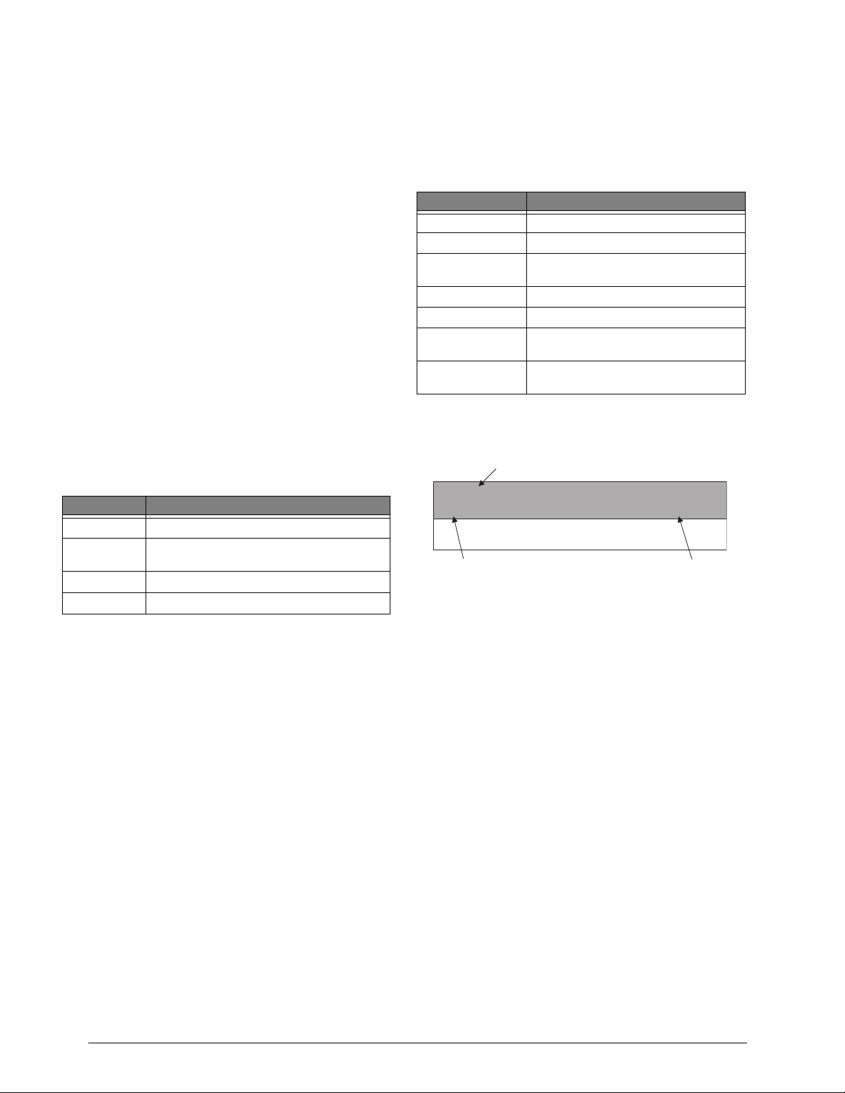
System settings are explained below and on the following
pages. They appear as follows:
S e t t i n g N a m e
S i r e n T i m e O u t
x x 0 0 2
I t e m N u m b e r
( P a r t i t i o n s - A l a r m s )
L o c a t i o n
System settings in this manual appear in the same order as
you would see them in Advent Downloader software. This
is done to eliminate confusion whether you are programming from a touchpad or the downloader.
If you prefer, Table A.13 on page 77 in Appendix A lists
the system settings in numeric order, by item number.
Included in the table are the item number, default setting,
and page number reference of the setting description.
Note
To keep track of panel programming, it is recommended
that you enter item number settings in Table A.13 in
Appendix A.
To exit program mode:
Press ‚ repeatedly.
Using Item Numbers
When prompted, entering an Item Number will “jump” you
to the setting associated with the number. Once at the set-
16
Advent Commercial Fire System
Page 19
Special Programming Settings Partitions/General Partition Settings
Clear Panel Memory
50002
(Default = n/a) It is recommended that you clear memory on all
newly installed panels before programming. Clearing memory
deletes setup values and resets all values to factory defaults.
To Clear Panel Memory:
1. Enter program mode.
2. Enter the installer code.
3. Enter item number 50002.
4. Press 99 and then
ƒ. Wait about a minute until touchpads
return to their default displays.
Note
Since all programming information is contained in memory, clearing memory deletes all existing programming
information except dealer values (if any).
Reviewing (List) Settings
00000
(Default = n/a) An easy way of listing all programming settings
and their values is provided. You can list all settings, or settings
starting at a selected item number.
To list all Settings:
1. Once in program mode enter the item number (00000).
2. Press ƒ to start listing settings from the beginning
or
enter the item number you wish to start at and press ƒ.
Touchpads will flash each of the item numbers and values
(if not protected by dealer password).
3. Press
‚ at any time to exit this menu.
Note
Displayed setting values may be viewed but not changed
using this procedure.
Partitions Act As Areas 17127 (Partitions-General Partition Settings)
(Default = off) Choose whether or not to treat partitions as areas.
If treated as areas:
Zones, touchpads, schedules, programming options, etc.,
belong to areas instead of partitions.
Users may “jump” from one area to another area using an
alphanumeric touchpad.
The word “partition” will be changed to “area” wherever
it is spoken, displayed, or printed.
To turn Areas On/Off:
Once the item number has been entered, enter 1 for on, or 0 for
off. Press ƒ to apply the new setting.
Touchpad Redirect Reset Time 17035 (Partitions-General Partition)
(Default = 10 seconds) This setting allows you to select the length
(in seconds) of inactivity (no menu activity) before a “jumped”
touchpad returns to its assigned area.
To set Touchpad Redirect Reset Time:
1. Once in program mode enter the item number.
2. Enter the desired length (5–60) and press ƒ.
Global Account Reporting 17093 (Partitions-General Partition)
(Default = off) The setting enables the panel to report events as a
system.
When set to on:
The panel will use system account and area numbers when
reporting events.
The panel will only perform one automatic phone test (not
one for each partition/area).
Advent Commercial Fire System
To turn Global Account Reporting On/Off:
Once the item number has been entered, enter 1 for on, or 0 for
off. Press ƒ to apply the new setting.
Partitions Enabled
xx068 (Partitions-General Partition Settings)
(Defaults = Partition/Area 1 - on, all others off) Choose whether
or not to enable the partition/area. Partition/Area 1 is always
enabled.
To turn a Partition/Area On/Off:
Once the item number has been entered, enter 1 for on, or 0 for
off. Press ƒ to apply the new setting.
17
Page 20

Account Number 1 Account Number 2
1: xx116, 2: xx117 (Partitions-General Partition)
(Defaults = 00000000) Enter an 8 digit account number. Each
partition/area may have two account numbers. Account number 1
will use the primary phone number to report partition/area events,
while account number 2 will use the secondary phone number to
report partition/area events.
Account Number Format:
for 0 enter 00
for 1 enter 01
for 2 enter 02
for 3 enter 03
for 4 enter 04
for 5 enter 05
for 6 enter 06
for 7 enter 07
for 8 enter 08
for 9 enter 09
for A enter 10
for B enter 11
for C enter 12
for D enter 13
for E enter 14
for F enter 15
To enter an Account Number:
1. Once the desired item number has been entered the current account number will be displayed.
2. Enter the new account number using the list above. For example, if you wanted the account number to be “123456AB,” at the keypad you would enter “01, 02, 03, 04, 05, 06, 10, 11.”
3. Press
ƒ and the touchpad displays the new account num-
ber.
Note
Account numbers must equal 8 characters. If you enter
less than 8 characters the panel will automatically replace
the blank spaces with leading zeros (0).
Partition/Area Text 49004 (Partitions-General Partition Settings)
(Default = none) Use the following guidelines to assign each
partition/area a name.
Use the item numbers that appear in Table B.2 on page
page 92 for characters and words listed there.
If a desired word does not appear in Table B.2, create it
using the characters (custom text).
When using words from Table B.2, spaces between them
appear automatically. When using characters from Table
B.2 to create words, you must reserve an item number for
a ‘space’ after the word.
Each character or word uses up one item number. For
example, a word from the list counts as one item number.
A created word (such as BOY’S) counts as six item numbers—4 letters, 1 apostrophe, and 1 space.
Only 8 item numbers are allowed for each partition/area
name, so plan ahead before programming partition/area
text. You may need to abbreviate words to avoid running
out of item numbers.
To program Partition/Area Text:
1. Once in program mode enter 49004. The display
shows ENTER PARTITION NUMBER OR PRESS * TO
CANCEL.
2. Enter the desired partition number and press
ƒ. The dis-
play shows TEXT FOR PARTITION n IS current text.
ENTER TEXT NUMBERS OR PRESS # TO ACCEPT.
3. Enter the numbers of the desired characters or words. If
you make a mistake press
4. Once all numbers have been entered, press
‚ to start over.
ƒ to accept.
The display shows the new partition/area text.
To delete Partition/Area Text:
1. Once in program mode enter 49004. The display shows ENTER PARTITION NUMBER OR PRESS * TO CANCEL.
2. Enter the desired partition/area number and press
ƒ. The
display shows TEXT FOR PARTITION n IS current text.
ENTER TEXT NUMBERS OR PRESS # TO ACCEPT.
3. Enter
000 and press ƒ. The display shows TEXT FOR
PARTITION n IS NO TEXT.
18
Partition/Arming Settings
Exterior Siren Delay
xx113 (Partitions-Arming)
(Default = foothills setting allows you to set the delay (in
seconds) before an exterior siren sounds during and alarm. This
includes all high level alarms, except for auxiliary alarms, which
don’t sound exterior sirens. If set to off, exterior sirens sound
instantly. If set to on, exterior sirens sound after a 15-second
delay.
To turn Exterior Siren Delay On/Off:
Once the item number has been entered, enter 1 for on (15second delay), or 0 for off (no delay). Press ƒ to apply the new
setting.
Advent Commercial Fire System
Page 21
Partitions/Alarms
Daily Trouble Reporting Time
xx001 (Partitions-Alarms)
(Default = 12:00) This is the time of day when the system will
annunciate any existing trouble conditions. For Advent
Commercial Fire and Burglary panels, trouble(s) are annunciated
every 4 hours. If the Daily Trouble Reporting time is set at 12:00
pm then the system will announce trouble(s) at 12:00 pm, 4:00
pm, 8:00 pm, 12:00 am, 4:00 am, and 8:00 am.
To set the Daily Trouble Reporting Time:
Once the item number has been entered, enter the 4-digit time
(00:00–23:59) in 24 hour format and press ƒ.
Note
The Enable Daily Reporting of Partition Trouble setting (xx108) must be set to “on” for this setting to work.
Enable Daily Reporting of Partition Trouble
xx108 (Partitions-Alarms)
(Default = on) Enables annunciation of all trouble conditions at
LTi m e (
To turn Enable Daily Reporting of Partition Trouble on/off:
Once the item number has been entered, enter 1 for on (15second delay), or 0 for off (no delay). Press ƒ to apply the new
setting.
Siren Time Out
xx002 (Partitions-Alarms)
(Default = 16 Minutes) This is the number of minutes that the
alarm siren is allowed to sound. The siren will silence when this
value is reached.
To set Siren Sound Time:
Once the item number has been entered, enter the number of
minutes (01–30) you wish the siren to sound and press ƒ.
Tamper Signals from Fire Zones are Alarms
xx083 (Partitions-Alarms)
(Default = off) This setting enables the panel to generate a tamper
alarm (in addition to a trouble report) when tampering of a fire
zone is detected.
To set the Fire Tamper Response to On/Off:
Once the item number has been entered, enter 1 for on (alarm is
generated) or 0 for off (alarm not generated). Press ƒ to apply
the new setting.
Enable Keystroke Violation Alarm
xx076 (Partitions-Alarms)
(Default = off) This setting enables keypad tamper. When on, the
panel will generate a police alarm when it detects four or more
incorrect access code entry attempts that do not include a valid
access code. A tamper report is also sent to the central station.
To turn Enable Keystroke Violation Alarm On/Off:
Once the item number has been entered, enter 1 for on (generate
alarm and report) or 0 for off. Press ƒ to apply the new setting.
No Activity Tripped After
xx009 (Partitions-Alarms)
(Default = not active) This setting allows you to select the length
of time (in hours) the panel will wait after not detecting any
activity before initiating a no-activity pre-alarm. Once a noactivity pre-alarm is initiated the panel will wait until the time in
the Delay Between No Activity Trip and Alarm setting (xx010)
expires before generating an alarm.
To set the No Activity Tripped After time:
1. Once the item number has been entered, enter the number
of hours (1–24) you wish the panel to wait before initiating a no-activity pre-alarm, or 0 for not active.
2. Press
ƒ to apply the new setting.
Generate Alarm for Unarmed Tamper Signals
xx079 (Partitions-Alarms)
(Default = off) This setting determines whether a tamper alarm is
generated for a zone that is not armed (applies to non-fire zones
only). If on, a zone tamper alarm is generated when a zone tamper
is detected in any arming level. If off, an alarm is only generated
when the zone is in an active level.
To turn Alarm for Unarmed Tamper Signals On/ Off:
Once the item number has been entered, enter 1 for on (alarm in
all levels), or 0 for off (alarm in active levels). Press ƒ to apply
the new setting.
Advent Commercial Fire System
Delay Between No Activity Trip and Alarm
xx010 (Partitions-Alarms)
(Default = 5 Minutes) This setting allows you to select the length of time (in minutes) allowed after the No Activity Tripped After setting (xx009) time has expired. If no activity is generated during this time the panel sends a report to the central station. If the user(s) generate activity within this delay period no report will be sent.
To set the Delay Between No Activity Trip and Alarm:
Once the item number has been entered, enter the number of
minutes (1–10) you wish the panel to wait before sending a
report. Press
ƒ to apply the new setting.
Note
If the No Activity Tripped After setting (xx009) is set to 0
(not active) this setting will have no affect.
19
Page 22
Generate Alarm for Suspicion Trips
xx078 (Partitions-Alarms)
(Default = on) This setting allows you to enable the panel to
generate a suspicion trip alarm. If on, and suspicion zones are
tripped, an alarm will be generated after the Delay Between
Suspicion Zone Trip and Alarm Generated (xx015) expires. If off,
the tripping of suspicion zones will not generate an alarm.
To turn Generate Alarm for Suspicion Trips On/ Off:
Once the item number has been entered, enter 1 for on or 0 for
off. Press ƒ to apply the new setting.
Delay Between Suspicion Zone Trip and Alarm Generated
xx015 (Partitions-Alarms)
(Default = 05 Minutes) Select the length of time in minutes in
which an alarm can be avoided after a suspicion zone is tripped.
This allows the user time to prevent a false alarm from being
generated.
Programming the Delay Between Suspicion Trip and Alarm Generated:
Once the item number has been entered, enter the number of
minutes (1–15) you wish the panel to wait before going into
alarm. Press ƒ to apply the new setting.
Note
If the Generate Alarm for Suspicion Trips setting (xx078)
is set to off, this setting will have no effect.
First Trip Local Second Trip Event
xx080 (Partitions-Alarms)
(Default = off) If on, the first zone trip in a two trip zone type (18
or 77) causes a local police alarm. A second zone trip from a
different zone, occurring within four minutes of the first zone trip,
generates a report. Zones must reside in the same partition/area. If
off, the first zone trip starts a timer and the second zone trip
causes the alarm and report.
To turn this setting On/Off:
Once the item number has been entered, enter 1 for on or 0 for
off. Press ƒ to apply the new setting.
Agent Release Zone 1 Agent Release Zone 2
1: xx122, 2: xx123 (Partitions-Alarms)
(Default = Off) This setting allows you to specify which zones,
when tripped, cause an output to release an extinguishing agent.
Note
All aspects of an agent release should occur in the same
partition. All zones, outputs, and devices relating to an
agent release should physically reside and be programmed into the same partition.
Select the zone number that, when tripped, causes an agent
release.
Note
This option is not available in UL-864 version.
To turn this setting On/Off:
Once the item number has been entered, enter 1 for on or 0 for
off. Press ƒ to apply the new setting.
Manual Agent Release Delays
xx125 (Partitions-Alarms)
(Default = 0) This setting allows you to specify delay times (0-30
seconds) before an agent is released after an alarm has been
triggered. Manual agent release cannot be aborted.
Note
This option is not available in UL-864 version.
To turn this setting On/Off:
Once the item number has been entered, enter 1 for on or 0 for
off. Press ƒ to apply the new setting.
Automatic Agent Release Delays
xx124 (Partitions-Alarms)
(Default = 30) This setting allows you to set the automatic agent
release delay time (0-60 seconds). Automatic agent release may
be aborted during the delay.
Note
This option is not available in UL-864 version.
To turn this setting On/Off:
Once the item number has been entered, enter 1 for on or 0 for
off. Press ƒ to apply the new setting.
Disable Siren
xx081 (Partitions-Alarms)
(Default = on) Select whether or not you want to disable siren
time-out for fire alarms. If disabled, a siren will continue to sound
until the system is disarmed.
Note
This option is not available in UL-864 version.
To turn this setting On/Off:
Once the item number has been entered, enter 1 for on or 0 for
off. Press ƒ to apply the new setting.
20
Advent Commercial Fire System
Page 23
Partitions/X10 Partitions/Reporting
X10 House Code 1
xx022 (Partitions-X10)
(Default = Partition/Area Number) The house code is a number
from 1 to 16 (representing A–P) used to communicate panel
signals to line carrier devices such as X10 Lamp, Appliance, and
Universal Modules. You can have up to two house codes per
partition/area.
Enter the panel house code setting used for the first 16 X10 line
carrier devices. The system commands “All Lights On/Off” or
“All Units On/Off” control only modules with House Code 1
(within respective partition/area). See Table B.5 on page 97 for
information on defaults.
Entering House Code 1:
Once the item number has been entered, enter the desired house
code (1–16). Press ƒ to apply the new setting.
Light Control
xx069 (Partitions-Reporting)
(Default = off) If on, users must enter a valid access code before
controlling lights. If off, an access code is not required for light
control.
To turn Light Code On/Off:
Once the item number has been entered, enter 1 for on (access
code required), or 0 for off. Press ƒ to apply the new setting.
Device Control
xx070 (Partitions-Reporting)
(Default = off) If on, users must enter a valid access code before
controlling devices. If off, an access code is not required for
device control.
X10 House Code 2
xx023 (Partitions-X10)
(Default = Partition/Area Number + 8) Enter the panel house code
setting used for the last 16 X10 line carrier devices within
respective partition/area. See for information on defaults.
Entering House Code 2:
Once the item number has been entered, enter the desired house
code (1–16). Press ƒ to apply the new setting.
Non X10 Output 1 (menu output 33)
Non X10 Output 2 (menu output 34)
Non X10 Output 3 (menu output 35)
Non X10 Output 4 (menu output 36)
Non X10 Output 5 (menu output 37)
Non X10 Output 6 (menu output 38)
Non X10 Output 7 (menu output 39)
Non X10 Output 8 (menu output 40)
1: xx049, 2: xx050, 3: xx051, 4: xx052, 5: xx053, 6: xx054, 7: xx055, 8: xx056 (Partitions-X10)
(Default = none) There are 40 menu outputs per partition/area.
The first 32 are X10 outputs, the last 8 are non X10 outputs. All
X10 outputs (menu outputs 1-32) are automatically linked to X10
devices. Non X10 outputs (menu outputs 33-40) must be linked to
a programmable output in order to control a light or device.
Note
All menu outputs must be programmed (learned) into the
panel before they will function. See “Fixed Output Settings” on page 42 for more information.
To turn Device Control On/Off:
Once the item number has been entered, enter 1 for on (access
code required) or 0 for off. Press ƒ to apply the new setting.
Latchkey Access
xx071 (Partitions-Reporting)
(Default = off) If on, users must enter a valid access code before
accessing the Latchkey setting. If off, an access code is not
required to access the Latchkey setting. For more information on
Latchkey, please see the User’s Manual.
To turn Latchkey Access On/Off:
Once the item number has been entered, enter 1 for on (access
code required) or 0 for off. Press ƒ to apply the new setting.
Report Partition Events to Central Station
xx088 (Partitions-Reporting)
(Default = on) If on, the panel will report partition/area events to
the central station.
To turn Reporting Partition Events to Central Station On/Off:
Once the item number has been entered, enter 1 to turn partition/
area event reporting on or 0 turn reporting off. Press ƒ to apply
the new setting.
Linking Non X10 Outputs:
1. Enter the item number for the desired non X10 output.
2. Enter the desired programmable output number (1–100),
then press
Advent Commercial Fire System
ƒ to confirm the selection.
Cancel Event Cancels Report
xx089 (Partitions-Reporting)
(Default = on) If on, the panel will cancel the sending of an alarm
report (to central station) if the event is canceled before the delay
between generated standard alarm and alarm reporting (xx013)
expires.
To turn Cancel Event Cancels Report On/Off:
Once the item number has been entered, enter 1 to turn the
setting on (canceled event cancels report) or 0 to turn it off. Press
ƒ to apply the new setting.
21
Page 24
Print Partition/Area Events
xx091 (Partitions-Reporting)
(Default = on) If on, the panel will print partition/area events on a
local printer.
To Print Partition/Area Events:
Once the item number has been entered, enter 1 (on) to enable
printing of partition/area events or 0 (off) to disable printing of
partition/area events. Press ƒ to apply the new setting.
Delay Between Generated Fire Alarm and Alarm Reporting
xx014 (Partitions-Reporting)
(Default = 0 minutes) This setting allows you to specify the length
of time (in minutes) between the time a fire alarm condition is
detected, and a report is sent to the central station. This allows
users time to cancel a false alarm.
Note
If Cancel Event Cancels Report setting (xx089) is set to
off, this setting will have no affect.
Delay Between Generated Panic Alarm and Alarm Reporting
xx012 (Partitions-Reporting)
(Default = 05 seconds) This setting allows you to specify the
length of time (in seconds) between the time a panic alarm
condition is detected, and a panic report is sent to the central
station. This allows users time to cancel a false alarm.
Note
If Cancel Event Cancels Report setting (xx089) is set to
off, this setting will have no affect.
Specifying the Delay Between Generated Panic Alarm and Alarm Reporting:
Once the item number has been entered, enter the number of
seconds (1–120) you wish the panel to wait before sending a
panic report. Press ƒ to apply the new setting.
Delay Between Generated Standard Alarm and Alarm Reporting
xx013 (Partitions-Reporting)
(Default = 05 seconds) This setting allows you to specify the
length of time (in seconds) between the time a non-panic and nonfire alarm condition is detected, and a report is sent to the central
station. This allows users time to cancel a false alarm.
Note
If Cancel Event Cancels Report setting (xx089) is set to
off, this setting will have no affect.
Specifying the Delay Between Generated Standard Alarm and Alarm Reporting:
Once the item number has been entered, enter the number of
seconds (1–120) you wish the panel to wait before sending a
report. Press ƒ to apply the new setting.
Specifying the Delay Between Generated Fire Alarm and Alarm Reporting:
Once the item number has been entered, enter the number of
minutes (0–15) you wish the panel to wait before sending a
report. Press ƒ to apply the new setting.
Second Fire Alarm Ends Reporting Delay
xx090 (Partitions-Reporting)
(Default = on) If on, and a fire report delay is in progress, a
second fire alarm condition will end the delay between generated
fire alarm and alarm reporting (xx014), immediately sending a
report to the central station.
Programming Second Fire Alarm Ends Reporting Delay:
Once the item number has been entered, enter 1 to turn the
setting on (second alarm ends delay) or 0 to turn it off. Press ƒ
to apply the new setting.
Second Intrusion Causes Report
xx077 (Partitions-Reporting)
(Default = off) If on, the first trip of an intrusion zone causes a
local police alarm. A second trip (different intrusion zone) within
four minutes generates a report. If off, the first trip of an intrusion
zone generates both an alarm and report.
To set the Second Intrusion Causes Report:
Once the item number has been entered, enter 1 to turn the
setting on or 0 to turn it off. Press ƒ to apply the new setting.
Generate Restoral Reports for Reporting Zone Types
xx112 (Partitions-Reporting)
(Default = off) If on, restoral reports are generated for all
reporting zone types (which require restoral). If off, the zone type
definition dictates whether on not a restoral report is generated.
22
To turn Generate Restoral Reports for Reporting Zone Types On/Off:
Once the item number has been entered, enter 1 to turn the
setting on or 0 to turn it off. Press ƒ to apply the new setting.
Advent Commercial Fire System
Page 25
Audible Verification at Close Report
xx098 (Partitions-Reporting)
(Default = off) When on, the panel will locally verify that a
closing report has been sent to the central station with an audible
signal.
Note
In order for this setting to work, Exterior Arming Verification setting (xx097) must be set to “on.”
To turn Audible Verification at Close Report On/ Off:
Once the item number has been entered, enter 1 to turn the
setting on or 0 to turn it off. Press ƒ to apply the new setting.
Activity Fault Threshold 1 Activity Fault Threshold 2 Activity Fault Threshold 3
1: xx018, 2: xx019, 3: xx020 (Partitions-Arming)
(Defaults = Threshold 1-10, Threshold 2-30, Threshold 3-50)
This setting allows you to specify the number of disarms without
any activity before zone activity trouble is generated.
Specifying Activity Fault Thresholds:
Once the item number has been entered, enter the number of
disarms before zone activity trouble is generated (2–255). Press
ƒ to apply the new setting.
Partitions/Arming
Enable Arming Level 2 Enable Arming Level 3 Enable Arming Level 4 Enable Arming Level 5
2: xx025, 3: xx026, 4: xx027, 5: xx028 (Partitions-Arming)
(Default = on) If on, the selected arming level will be enabled
(level 1 is always enabled) in the selected partition/area. Users
will then have access to this arming level. An arming level is the
degree of security protection set at the panel.
To Enable Arming Level:
Once the item number has been entered, enter 1 to turn the
setting on (level enabled) or 0 to turn it off. Press ƒ to apply the
new setting.
Default Keyfob Schedule Arming Level
xx118 (Partitions-Arming)
(Default = 3) This setting allows you to select the arming level
(2–5) the panel arms to when armed by a keyfob or schedule (auto
arming).
Specifying Default Keyfob Schedule Arming Level:
Once the item number has been entered, enter the keyfob/
scheduled arming level (2–5). Press ƒ to apply the new setting.
Default Keyswitch Arming Level
xx120 (Partitions-Arming)
(Default = 3) This setting allows you to select the arming level
(2–5) the panel arms to when armed by a keyswitch.
Specifying Default Keyswitch Arming Level:
Once the item number has been entered, enter the keyswitch
arming level (2–5). Press ƒ to apply the new setting.
Enable Scheduled Arming
xx094) (Partitions-Arming)
(Default = on) This setting allows you to select whether or not to
allow the system to arm/disarm according to a schedule.
To turn Enable Scheduled Arming On/Off:
Once the item number has been entered, enter 1 to enable
scheduled arming or 0 to turn it off. Press ƒ to apply the new
setting.
Time Between Arming Notification and Arming
xx007 (Partitions-Arming)
(Default = 10 minutes) This is the amount of time between the
start of arming notification and when the partition/area is armed
by a schedule (auto arming). This notifies users that a scheduled
arm is about to occur and allows time for users to vacate the
premises.
To set the Time Between Arming Notification and Arming:
Once the item number has been entered, enter the number of
minutes (05–30) that will pass between notification and arming.
Press ƒ to apply the new setting.
Extension Time
xx008 (Partitions-Arming)
(Default = 30 minutes) This is the amount of time by which a
scheduled arming period will be suspended during the arming
notification period. For example, let’s say the extension is entered
when there is four minutes left in the delay. Once the extension
has expired the system will start counting down the remaining
four minutes.
To set the Extension Time:
Once the item number has been entered, enter the number of
minutes (15–120) users will be able to extend the notification
period and press ƒ.
Advent Commercial Fire System
23
Page 26
Enable Auto Force Arming
xx092 (Partitions-Arming)
(Default = on) If on, any protesting zone(s) will be bypassed upon
arming. If off, then the partition/area will not arm if any zone(s)
are protesting.
To turn Enable Auto Force Arming On/Off:
Once the item number has been entered, enter 1 to turn the
setting on or 0 to turn it off. Press ƒ to apply the new setting.
Enable Automatic Unbypass
xx096 (Partitions-Arming)
(Default = off) If on, an indirectly bypassed zone will
automatically be unbypassed once the door, window, etc., has
been closed for 30 seconds. This setting only applies to delayed
zones.
To turn Enable Automatic Unbypass On/Off:
Once the item number has been entered, enter 1 to turn the
setting on or 0 to turn it off. Press ƒ to apply the new setting.
Enable Quick Arming
xx093 (Partitions-Arming)
(Default = on) If on, anyone can arm the panel and increase
arming levels without an access code. A valid access code is still
required to decrease arming levels or disarm the system. Quick
arm works as follows:
Level 3 to 5 = no code
Level 3 to 4 = code
Level 4 to 3 = not code
Level 5 to 3 = code
Level 1 to 2 = no code
Level 1 to 3 = no code
Level 1 to 4 = no code
Level 1 to 5 = no code
To turn Enable Quick Arming On/Off:
Once the item number has been entered, enter 1 to turn the
setting on or 0 to turn it off. Press ƒ to apply the new setting.
Exterior Arming Verification
xx097 (Partitions-Arming)
(Default = off) If on, exterior sirens will produce arming
verification sounds notifying users that the system was armed.
Note
In order for this setting to work, Audible Verification at
Close Reports setting (xx098) must be set to “on.”
To turn Exterior Arming Verification On/Off:
Once the item number has been entered, enter 1 to turn the
setting on or 0 to turn it off. Press ƒ to apply the new setting.
Number of Zones that can be Bypass
xx017 (Partitions-Arming)
(Default = 250) Select the number of zones that may be bypassed
at once. See Table B.1 on page 87 for information on which zone
types may be bypassed.
Enable Swinger Bypass
xx095 (Partitions-Arming)
(Default = on) If on, a zone that exceeds the set swing count
(xx021) during a single arming period will automatically be
bypassed. Changing the arming level restores all automatically
bypassed zones and resets the swing count.
To turn Enable Swinger Bypass On/Off:
Once the item number has been entered, enter 1 to turn the
setting on or 0 to turn it off. Press ƒ to apply the new setting.
Swing Count (Auto Bypass Trips)
xx021 (Partitions-Arming)
(Default = 3) Select the maximum number of report attempts that
one zone can generate during a single arming period before the
panel automatically bypasses that zone.
All automatically bypassed zones, and the swing count, will reset
if the system clock reaches midnight or an arming level change
occurs.
To set the Swing Count:
Once the item number has been entered, enter the desired swing
count (1–8) and press ƒ.
Standard Entry Delay
xx003 (Partitions-Arming)
(Default = 32 seconds) Enter the length of the standard entry
delay (in seconds). This is the number of seconds the user has to
disarm the system after tripping a standard delay zone. If the
system isn’t disarmed within this time period an alarm is
generated.
To set the Standard Entry Delay:
Once the item number has been entered, enter the number of
seconds (24–120) users will have to disarm the system. Press ƒ
to apply the new setting.
To program the Number of Zones that can be Bypassed:
Once the item number has been entered, enter the number of
zones that may be bypassed at once (0–250). Press ƒ to apply the
new setting.
24
Advent Commercial Fire System
Page 27
Exit Delay
xx004 (Partitions-Arming)
(Default = 32 seconds) Enter the length of the standard exit delay
(in seconds). This is the number of seconds the user has to exit the
premises through a standard delay door after arming the system.
If the user trips a zone after this time period has expired, an alarm
is generated.
To set the Exit Delay:
Once the item number has been entered, enter the number of
seconds (24–120) users will have to exit the premises after arming
the system. Press ƒ to apply the new setting.
Extended Delay
xx005 (Partitions-Arming)
(Default = 2 minutes) Enter the length of the extended delay. The
extended delay time determines how much time (in minutes) the
user has to enter or exit the premises through an extended delay
door without causing an alarm.
To set the Extended Delay:
Once the item number has been entered, enter the number of
minutes (1–10) for the extended delay and press ƒ.
Early Termination Delay
xx101 (Partitions-Arming)
(Default = off) If on, the system will arm as soon as it detects a
delay zone closing. Once a person leaves through an exit delay
door and the door closes, the exit delay is terminated and the
system is armed.
Note
Cannot be used with One-Time Reset Enabled setting (xx102).
Fast Beep Duration
xx006 (Partitions-Arming)
(Default = 10 seconds) Enter the length of time (in seconds) that
fast beeps will sound during the last portion of the exit delay to
signal the delay is ending.
To set the Fast Beep Duration:
Once the item number has been entered, enter the number of
seconds (5–15) fast beeps will sound before the end of the delay
and press ƒ.
Fast Beeps at End of Exit Delay Only
xx100 (Partitions-Arming)
(Default = on) If on, only the fast beeps at the end of the exit
delay will sound. If off, slow exit delay beeps will sound followed
by the fast beeps at the end of the delay.
To turn Fast Beeps at End of Exit Delay Only On/ Off:
Once the item number has been entered, enter 1 to turn the
setting on or 0 to turn it off. Press ƒ to apply the new setting.
Beeps During Standard Entry Delay Only
xx103 (Partitions-Arming)
(Default = off) If on, beeps only sound during the standard entry
delay. If off, beeps sound during all segments of an entry delay
including standard, extended, and twice extended.
To turn Beeps During Standard Entry Delay Only On/Off:
Once the item number has been entered, enter 1 to turn the
setting on or 0 to turn it off. Press ƒ to apply the new setting.
To turn Early Termination Delay On/Off:
Once the item number has been entered, enter 1 to turn the
setting on or 0 to turn it off. Press ƒ to apply the new setting.
One-Time Reset Enabled
xx102 (Partitions-Arming)
(Default = off) If on, the system will allow a one-time reset of the
standard exit delay. If a user leaves through a delay door and the
door closes, they may re-enter through the door within the exit
delay time period and the system will reset the exit delay.
Note
Cannot be used with Early Termination Enabled setting
(xx101).
To turn One-Time Reset Enabled On/Off:
Once the item number has been entered, enter 1 to turn the
setting on or 0 to turn it off. Press ƒ to apply the new setting.
Advent Commercial Fire System
25
Page 28
Partitions/Zones
Announce and Display Zone Text with Chime
xx110 (Partitions-Zones)
(Default = off) If on, zone text will be announced over speakers
and displayed on touchpads whenever a chime sounds (the sensor
is open or closed).
Note
Only partition/area 1 has voice capabilities.
To turn Announce and Display Zone Text with Chime On/Off:
Once the item number has been entered, enter 1 to turn the
setting on or 0 to turn it off. Press ƒ to apply the new setting.
Chime On Zone Restoral
xx111 (Partitions-Zones)
(Default = off) If on, a chime will sound whenever a zone is
restored.
To turn Chime on Zone Restoral On/Off:
Once the item number has been entered, enter 1 to turn the
setting on or 0 to turn it off. Press ƒ to apply the new setting.
Key or Code Needed for Special Fire Touchpad Keys
xx082 (Partitions-Zones)
(Default = on) If on, then a key or code must be used before using
the special panic keys (on fire touchpad) to acknowledge an
alarm, silence an alarm, or perform a fire alarm drill. If off, then
no key or code is required to use the special panic keys.
To turn Key or Code Needed for Special Fire Touchpad Keys On/Off:
Once the item number has been entered, enter 1 to turn the
setting on (key or code required) or 0 to turn it off. Press ƒ to
apply the new setting.
Zone Test Time Out
xx011 (Partitions-Zones)
(Default = 30 minutes) Enter the length of time (in minutes) after
which a zone test automatically times out (ends).
To set the Zone Test Time Out:
Once the item number has been entered, enter the number of
minutes (5–120) before a zone test ends and press ƒ.
Disarm Key Arm Key Lights Key Star Key Lights/Star Keys Arm Level 2 Arm Level 3 Arm/Star Keys Disarm/Lights Keys
xx057, xx058, xx059, xx060, xx061, xx063, xx064, xx065, xx066 (Partitions-Zones)
(Defaults = Unlock-4, Lock-9, Lights-15, Star-12, Light/Star-3,
Level 2-6, Level 3-5, Arm/Star-16, Disarm/Lights-16) These
settings allow you to specify how the system behaves when
specific keychain touchpad button or button combinations are
pressed.
Special Action Assignments:
0- not used
1- not used
2- not used
3- auxiliary panic (only used for item no. xx061)
4- arm to level 1
5- arm to level 2
6- arm to level 3
7- arm to special level 4
8- arm to special level 5
9- arm to closed level
10- arm to closed level with no delay
11- arm to closed level with Latchkey
12- increment arming level from 0 to 1, 1 to 2, or 2 to 3
only
13- turn all* lights on
14- turn all* lights off
15- toggle all* lights
16- do nothing
* all lights having the first (of two) house codes in the partition.
Specifying Keychain Touchpad Button Action:
1. Once the desired item number has been entered, enter the
special action assignment number (3–16) from the above
list.
2. Press
Enable Auxiliary/Medical Panic Keys
xx086 (Partitions-Zones)
(Default = on) Choose whether or not to enable the Auxiliary
panic buttons on non-fire touchpads. If enabled, when a user
presses and holds the Auxiliary panic buttons or presses them
twice, an auxiliary or medical alarm is generated. See Auxiliary/
Medical Assignments setting (xx084).
ƒ to apply the new setting.
26
Turning Enable Auxiliary/Medical Panic Keys On/ Off:
Once the item number has been entered, enter 1 to turn the
setting on (enabled) or 0 to turn it off. Press ƒ to apply the new
setting.
Advent Commercial Fire System
Page 29
Enable Police Panic Keys
xx085 (Partitions-Zones)
(Default = on) Choose whether or not to enable the Police panic
buttons on non-fire touchpads. If enabled, when a user presses
and holds the police panic buttons or presses them twice, a police
alarm is generated.
Turning Enable Police Panic Keys On/Off:
Once the item number has been entered, enter 1 to turn the
setting on (enabled) or 0 to turn it off. Press ƒ to apply the new
setting.
Dealer Access Code 17107 (Codes)
(Default = none) Enter a six-digit Dealer Access code. This code
is used to access special programming menus when the panel is in
program mode.
To set the Dealer Access Code:
1. Once the item number has been entered, enter any sixdigits (0–9) then press
ƒ.
2. When prompted, enter the six-digit code again (for verification), and press
ƒ.
3. The touchpad will display NEW CODE OK.
Enable Fire Panic Keys
xx087 (Partitions-Zones)
(Default = on) Choose whether or not to enable the Fire panic
buttons on non-fire touchpads. If enabled, when a user presses
and holds the fire panic buttons or presses them twice, a fire alarm
is generated.
Turning Enable Fire Panic Keys On/Off:
Once the item number has been entered, enter 1 to turn the
setting on (enabled) or 0 to turn it off. Press ƒ to apply the new
setting.
Auxiliary/Medical Assignment
xx084 (Partitions-Zones)
(Default = on) Choose whether the Auxiliary/Medical panic
buttons are used to produce an auxiliary (on) or medical (off)
alarm.
Note
In order for an auxiliary or medical alarm to be produced
by the pressing of the panic buttons, they must be
enabled. See the Enable Auxiliary/Medical Panic Keys
setting xx086.
Selecting the Alarm Type:
Once the item number has been entered, enter 1 to turn the
setting on (auxiliary) or 0 to turn it off (medical). Press ƒ to
apply the new setting.
Codes
The settings below cover only installer programming codes.
For information on user access code programming, please
refer to the User’s Guide.
Changing/Deleting the Dealer Access Code:
1. Once the item number has been entered, enter the sixdigit dealer code.
2. Wait until the touchpad displays ENTER NEW CODE then
enter a new six-digit dealer code or,
enter 0 + ƒ to delete the dealer access code (no
code).
3. Enter the new code again.
4. The touchpad will display NEW CODE OK.
Downloader Access Code 17108 (Codes)
(Default = 12345) Enter a five-digit access code to be used in
conjunction with downloader programming.
Note
This code must match (or be left at default) the downloader access code programmed in downloader in order
for the two to communicate.
Changing the Downloader Access Code:
1. Enter the item number.
Note
If a Dealer Access Code has been programmed, you will
be prompted to enter it.
2. Once the Dealer Access Code has been entered (if applicable) the touchpad will display the current Downloader
Access Code.
3. Enter any five-digits (0–9) for the new Downloader
Access code, then press
ƒ.
Advent Commercial Fire System
27
Page 30
Access Code Length 50013 (Codes)
(Default = 4) Select the required length of all installer, primary,
and user access codes. If the access code length is changed, then
all access codes will automatically be updated to the correct
length. Access codes that contained less digits than the new
length will be given leading zeros (1234 = 001234). Access codes
that contained more digits than the new length will be have the
first digit(s) removed (987654 = 7654).
Changing the Access Code Length:
1. Enter the item number. The current code length will be displayed.
2. Enter the new code length (4–6) and press
Phone Settings
Enable DTMF Dialing Line 1 Enable DTMF Dialing Line 2
1: 17094, 2: 17095 (Phone)
(Default = on) Select whether or not you want to enable the phone
line for DTMF (touch-tone) dialing. If off, the panel will dial
using pulse format.
ƒ.
To set the Dialing format:
Once the item number has been entered, enter 1 to turn this
setting on (DTMF dialing) or
ƒ to apply the new setting.
Press
0 to turn it off (pulse dialing).
Number of Attempts Before Reporting Failure RF Buddy
17101 (Phone)
(Default = 5) Set the number of dialing attempts (to central
station) before a buddy transmission is generated.
Note
Not investigated by UL.
To set the number of Attempts:
Once the item number has been entered, enter the number of
buddy dial attempts (0-11)* and press ƒ.
* 0 = immediate transmit request, 11 = no transmit request.
No Phone Line Attached 17069 (Phone)
(Default = off) Turn this setting on if there is no phone line
connected to the panel. When on, the panel will not check for
phone line failure.
Turning No Phone Line Attached On/Off:
Once the item number has been entered, enter 1 to turn this
setting on (no phone line) or 0 to turn it off (phone line). Press ƒ
to apply the new setting.
Phone Line 1 Dialing Prefix Phone Line 2 Dialing Prefix
1: 17105, 2: 17106 (Phone)
(Default = none) Enter up to a six-digit phone line dialing prefix.
Use this setting to access an outside line, disable call waiting, etc.
Line Dial Prefix Format:
Enter 00–09 for numbers 0-9
Enter 10 for * (star)
Enter 11 for # (pound)
Enter 12 for D (1–5 second delay)
Enter 13 for W (wait for dial tone)
Setting a Line Dialing Prefix:
1. Once the desired item number has been entered the current line dial prefix will be displayed.
2. Enter up to a six-digit phone line dialing prefix using the
format above and press
ƒ.
Deleting a Line Dialing Prefix:
1. Once the desired item number has been entered the current line dial prefix will be displayed.
2. Enter
0 + ƒ. The touchpad will display NO DATA.
28
Advent Commercial Fire System
Page 31

System Account Number 1 System Account Number 2
1: 17102, 2: 17103 (Phone)
(Default = 00000000) Enter an 8-digit system account number
which will identify the panel to the central station when reporting
system events. System Account Number 1 is reported on
reporting phone 1 and its backup. System account number 2 is
reported on reporting phone 2 and its backup.
Account Number Format:
for 0 enter 00
for 1 enter 01
for 2 enter 02
for 3 enter 03
for 4 enter 04
for 5 enter 05
for 6 enter 06
for 7 enter 07
for 8 enter 08
for 9 enter 09
for A enter 10
for B enter 11
for C enter 12
for D enter 13
for E enter 14
for F enter 15
To enter a System Account Number
1. Once the desired item number has been entered the current system account number will be displayed.
Note
If a Dealer Access Code has been programmed, you will
be prompted to enter it.
2. Enter the new system account number using the list above. For example, if you wanted the system account number to be “123456AB,” at the keypad you would enter “01, 02, 03, 04, 05, 06, 10, 11.”
3. Press
ƒ and the touchpad displays the new system
account number.
Note
System account numbers must equal 8 characters. If you
enter less than 8 characters the panel will automatically
replace the blank spaces with leading zeros (0).
Pager ID 17058 (Phone)
(Default = 00000) The Pager ID identifies the panel to pagerholders. Select the ID to be sent with pager reports.
Phone Test Interval 17034 (Phone)
(Default = 1 day [comm], 7 days [home nav]) Select the number
of days between automatic phone test reports to all enable central
station phone numbers. Entering 0 will disable automatic phone
test.
To set Phone Test Interval:
Once the item number has been entered, (17-034) enter the
number of days (0–255). Press ƒ to apply the new setting.
Specific Phone Number Settings
Specific phone number settings allow you to program central monitoring station, downloader, and pager phone numbers.
Note
If a Dealer Access Code has been programmed, you will
be prompted to enter it when setting/changing specific
phone settings.
Phone numbers 19–22 are central monitoring station
reporting phone numbers and function as follows:
19 = phone 1
20 = phone 1 backup
21 = phone 2
22 = phone 2 backup
Phone numbers 23–24 are downloader phone numbers and
function as follows:
23 = downloader
24 = downloader backup
Note
Downloader phone numbers are for commercial burglary
panels only.
Phone numbers 25–40 are reporting pager phone numbers
1 through 16.
Phone Number Enable
yy001 (Phone)
(Default = off) Select whether or not to enable the phone number.
If on, the panel will use the number when reporting or
downloading. If off, the number will be skipped.
To turn Phone Number Enable On/Off:
Once the item number has been entered (19001–24001), enter 1
to turn this setting on (call), or 0 to turn it off (no call). Press ƒ
to apply the new setting.
To set the Pager ID:
Once the item number has been entered, enter the 5-digit Pager ID
(00000–99999) to be sent with pager reports and press ƒ.
Advent Commercial Fire System
29
Page 32
Number to Dial
yy002 (Phone)
(Default = none) Enter up to a 24-digit phone number for
reporting or downloading.
Phone Number Format:
Enter 00–09 for numbers 0-9
Enter 10 for * (star)
Enter 11 for # (pound)
Enter 12 for D (1–5 second delay)
Enter 13 for W (wait for dial tone)
To enter Number to Dial:
1. Enter the desired item number (ex. 19002).
2. Enter the phone number using the list above. For example, if you wanted the phone number to be
“1235551212,” at the keypad you would enter “01, 02,
03, 05, 05, 05, 01, 02, 01, 02.”
3. Press
ƒ and the touchpad displays the new phone num-
ber.
Note
In order for the phone number to be used for reporting
events or downloading, it must be enabled. See the
Phone Number Enable setting (yy001) on page 29.
To delete a Number to Dial:
Enter the desired item number. Enter 0 + ƒ. The touchpad will
display NO DATA.
Number of Attempts
yy003 (Phone)
(Default = 5) Set the number of times (attempts) the panel will
dial (and report) to the reporting or downloader phone number.
Note
19003 for phones 1 and 2, 21003 for phones 3 and 4.
To set the Number of Dial Attempts:
Once the item number has been entered, enter the number of dial
attempts (5–10) and press ƒ.
Comm Format
yy004 (Phone)
(Default = Contact ID) Select the type of communication format
the panel will use when reporting events to the central station.
Note
Currently only Contact ID format is supported.
Report Panic Special
yy005 (Phone)
(Default = off) Choose how the panel formats touchpad panic
alarm reports to the central station. When on, touchpad panic
alarms report using the following special 3-digit codes:
Fire Panic—599
Police Panic—598
Auxiliary Panic—597
Medical Panic—596
When off, panics will report as “500” plus the bus device number.
For example, a keypad with bus device number “03” would report
as “503.”
Turning Report Panic Special On/Off:
Once the item number has been entered, enter 1 to turn this
setting on (report panic special), or 0 to turn it off (not special).
Press ƒ to apply the new setting.
System Pagers
Enabled Pager Phone Number
zz001 (Phone-Pagers)
(Default = off) Select whether or not to enable the pager phone
number. If on, number will report events to the pager. If off, the
number will be skipped when the panel is reporting to pagers.
To turn Enable Pager Phone Number On/Off:
Once the item number has been entered (25001–40001), enter 1
to turn this setting on (page), or 0 to turn it off (no page). Press
ƒ to apply the new setting.
Pager Number to Dial
zz002 (Phone-Pagers)
(Default = none) Enter up to a 24-digit phone number for pager
reporting.
Pager Phone Number Format
Enter 00–09 for numbers 0-9
Enter 10 for * (star)
Enter 11 for # (pound)
Enter 12 for D (1–5 second delay)
Enter 13 for W (wait for dial tone)
To enter a Pager Phone Number:
1. Enter the desired item number (ex. 25002).
2. Enter the phone number using the list above. For example, if you wanted the pager phone number to be
“1235551212,” at the keypad you would enter “01, 02,
03, 05, 05, 05, 01, 02, 01, 02.”
3. Press
ƒ and the touchpad displays the new pager phone
number.
Note
In order for the panel to report events to the pager the
pager phone number must be enabled. See Enable Pager
Phone Number setting (zz001).
30
To delete a Pager Phone Number:
Enter the desired item number. Enter 0 + ƒ. The touchpad will
display NO DATA.
Advent Commercial Fire System
Page 33
Number of Attempts
zz003 (Phone-Pagers)
(Default = 3) Set the number of times (attempts) the panel will try
to dial the pager phone number.
To set the Number of Dial Attempts:
Once the item number has been entered, enter the number of dial
attempts (3–10) and press ƒ.
Comm Format
zz004 (Phone-Pagers)
(Default = 1 [TAP at 1200 bps PSK]) Select the type of
communication format the panel will use when reporting events
to pagers.
Communication Formats:
Enter 0 for TAP at 300 bps (FSK)
Enter 1 for TAP at 1200 bps (PSK)
To set the Communication Format:
Once the item number has been entered, use the choices above to
select a communication format. Press ƒ to apply the new setting.
Character Format
zz005 (Phone-Pagers)
(Default = 1 [7/E/1]) Select the character format the panel will use
when reporting to pagers.
Character Formats:
Enter 0 for 8/N/1
Enter 1 for 7/E/1
To set the Character Format:
Once the item number has been entered, press 0 for 8/N/1
character format (off), or 1 for 7/N/1 character format (on). Press
ƒ to apply the setting.
Partition/Area 1 Pager Reports Partition/Area 2 Pager Reports Partition/Area 3 Pager Reports Partition/Area 4 Pager Reports Partition/Area 5 Pager Reports Partition/Area 6 Pager Reports Partition/Area 7 Pager Reports Partition/Area 8 Pager Reports
1: zz007, 2: zz008, 3: zz009, 4: zz010, 5: zz011, 6: zz012, 7: zz013, 8: zz014 (Phone-Pagers)
(Defaults = 0, phone 25-31 = 1) Select whether or not you want
partition/area events to report to pager(s).
To turn Partition/Area Report On/Off:
Once the item number has been entered, enter 1 to turn this
setting on (report), or 0 to turn it off (don’t report). Press ƒ to
apply the new setting.
Pager PIN #
zz015 (Phone-Pagers)
(Default = none) Enter up to a 15-digit pager PIN.
To enter a Pager PIN:
1. Enter the desired item number (ex. 25015).
2. Enter up to a 15-digit (0–9) pager PIN.
3. Press
Pager Max Message Length
zz016 (Phone-Pagers)
(Default = 120 characters) Set the maximum character length for
pager messages.
ƒ and the touchpad displays the pager PIN.
To set the maximum Pager Message Length:
Once the item number has been entered, enter the maximum
pager length (0–255) and press ƒ.
Pager System Reports
zz006 (Phone-Pagers)
(Default = off) Select whether or not you want system events
reported to pager.
To turn System Pager Report On/Off:
Once the item number has been entered, enter 1 to turn this
setting on (report), or 0 to turn it off (don’t report). Press ƒ to
apply the new setting.
Advent Commercial Fire System
Advanced Settings
&$87,21
Only qualified persons should make changes to advanced
phone settings.
Maximum Ring Cycle Time 17018 (Phone-Advanced Dialog Screen)
(Default = 67 milliseconds) Specify (in milliseconds) the
maximum cycle time for a ring signal.
To set the Maximum Ring Cycle Time:
Once the item number has been entered, specify the maximum
ring cycle time (0–255). Press ƒ to apply the new setting.
31
Page 34
DTMF on Time 17031 (Phone-Advanced Dialog Screen)
(Default = 3 [30 ms]) Specify the minimum duration of a valid
DTMF (touch-tone) tone in 10 millisecond increments (1–100 x
10 ms). This is the minimum amount of time that a phone number
button must be pressed in order to be valid.
To set the DTMF on Time:
Once the item number has been entered, specify the minimum
tone duration (1–100). Press ƒ to apply the new setting.
DTMF off Time 17032 (Phone-Advanced Dialog Screen)
(Default = 5 [50 ms]) Specify the minimum duration of pause
between DTMF (touch-tone) tones in 10 millisecond increments
(1–100 x 10 ms). This is the minimum amount of time required
between two phone number buttons being pressed.
To set the DTMF off Time:
Once the item number has been entered, specify the minimum
duration between tones (1–100). Press ƒ to apply the new
setting.
Minimum Cycles in a Valid Ring 17054 (Phone-Advanced Dialog Screen)
(Default = 2 cycles) Specify the minimum number of cycles in a
valid ring.
To set the Minimum Cycles in a Valid Ring:
Once the item number has been entered, specify the minimum
number of cycles (0–255). Press ƒ to apply the new setting.
Number of Ringlets Needed for a Valid Ring 17055 (Phone-Advanced Dialog Screen)
(Default = 1 burst) Specify the number of ring bursts in a valid
ring.
To set the Number of Ringlets Needed for a Valid Ring:
Once the item number has been entered, specify the number of
ring bursts (0–5). Press ƒ to apply the new setting.
Valid Ring at Beginning or End of Cycle 17091 (Phone-Advanced Dialog Screen)
(Default = off) Select to enable ring valid at beginning or end of
cycle.
To set the Valid Ring at Beginning or End of Cycle:
Once the item number has been entered, enter 1 to turn this
setting on (ring valid), or 0 to turn it off (ring not valid). Press ƒ
to apply the new setting.
Maximum Ringlet Burst Duration 17020 (Phone-Advanced Dialog Screen)
(Default = 250 [2500 ms]) Specify the maximum duration of a
valid ring burst in 10 ms increments (3–300 x 10 ms).
To set the Maximum Ringlet Burst Duration:
Once the item number has been entered, specify the maximum
ring burst duration (3–300). Press ƒ to apply the new setting.
Minimum Ringlet Burst Duration 17019 (Phone-Advanced Dialog Screen)
(Default = 40 [400 ms]) Specify the minimum duration of a valid
ring burst in 10 ms increments (3–300 x 10 ms).
To set the Minimum Ringlet Burst Duration:
Once the item number has been entered, specify the minimum
ring burst duration (3–300). Press ƒ to apply the new setting.
Maximum Pause Between Ringlets 17022 (Phone-Advanced Dialog Screen)
(Default = 0) Specify the maximum duration between valid ring
bursts in 10 millisecond increments (0–300 x 10 ms).
To set the Maximum Pause Between Ringlets:
Once the item number has been entered, specify the maximum
duration between ring bursts (0–300). Press ƒ to apply the new
setting.
Minimum Pause Between Ringlets 17021 (Phone-Advanced Dialog Screen)
(Default = 0) Specify the minimum duration between valid ring
bursts in 10 millisecond increments (0–300 x 10 ms).
To set the Minimum Pause Between Ringlets:
Once the item number has been entered, specify the minimum
duration between ring bursts (0–300). Press ƒ to apply the new
setting.
Maximum Pause Between Rings 17024 (Phone-Advanced Dialog Screen)
(Default = 450 [4500 ms]) Specify the maximum amount of time
allowed between valid rings in 10 millisecond increments (100–
999 x 10 ms).
To set the Maximum Pause Between Rings:
Once the item number has been entered, specify the maximum
time between rings (100–999). Press
ƒ to apply the new setting.
32
Advent Commercial Fire System
Page 35
Minimum Pause Between Rings 17023 (Phone-Advanced Dialog Screen)
(Default = 200 [2000 ms]) Specify the minimum amount of time
allowed between valid rings in 10 millisecond increments (100–
999 x 10 ms).
To set the Minimum Pause Between Rings:
Once the item number has been entered, specify the minimum
time between rings (100–999). Press ƒ to apply the new setting.
Phone Access Settings
Local Phone Settings
Local phone settings allow you to choose how phones
located on the same premises as the panel interact with the
system.
Enable Local Phone Access in Partition/Area 1 17085 (Phone Access)
(Default = off) This setting allows you to enable local phone
control in partition/area 1. If on, partition/area 1 may be
controlled by local on premises phones.
To turn Enable Local Phone Access in Partition/ Area 1 On/Off:
Once the item number has been entered, enter 1 to turn this
setting on, or 0 to turn it off. Press ƒ to apply the new setting.
Local Phone Connect Sequence 17056 (Phone Access)
(Default = #*) Enter up to a 4-digit DTMF (touch-tone) sequence
for local control. This is the sequence of numbers the user will
have to enter when accessing the panel locally (on-site)
Format:
Enter 00–09 for numbers 0-9
Enter 10 for * (star)
Enter 11 for # (pound)
To enter Local Phone Connect Sequence:
1. Enter the item number.
2. Enter the sequence using the format above. For example, if you wanted the sequence to be “12#*,” at the keypad you would enter “01, 02, 11, 10.”
3. Press
To delete the Local Phone Connect Sequence:
1. Enter the item number.
2. Enter
ƒ and the touchpad displays the new sequence.
0 + ƒ. The touchpad will display NO DATA.
Phone Device Override Sequence 17057 (Phone Access)
(Default = **##) Enter up to a 4-digit DTMF (touch-tone)
sequence for phone device override. This sequence will instruct
the panel to seize the line from the local phone and initiate a
remote connection. Users will be able to enter this sequence and
bypass any phone devices (answering machines, fax machines,
etc.) when calling from a remote phone.
Format:
Enter 00–09 for numbers 0-9
Enter 10 for * (star)
Enter 11 for # (pound)
To enter Phone Device Override Sequence:
1. Enter the item number.
2. Enter the sequence using the format above. For example, if you wanted the sequence to be “12#*,” at the keypad you would enter “01, 02, 11, 10.”
3. Press
ƒ and the touchpad displays the new sequence.
To delete Phone Device Override Sequence:
1. Enter the item number.
2. Enter 0 + ƒ. The touchpad will display NO DATA.
Max Delay Between Phone Panic Sequence 17030 (Phone Access)
(Default = 2 seconds) Specify the maximum time allowed (in
seconds) between keystrokes in a phone panic sequence. If this
delay is exceeded, a panic alarm will not be activated.
Setting the Max Delay Between Phone Panic Sequence:
Once the item number has been entered, enter the maximum delay
(1–5). Press ƒ to apply the new setting.
Local Phone Connect Time 17028 (Phone Access)
(Default = 5 seconds) Specify the maximum time allowed (in
seconds) between local phone off-hook and DTMF seize
sequence for local phone control. If the maximum time is
exceeded, remote phone control will be put on hold.
Setting the Local Phone Connect Time:
1. Once the item number has been entered, enter the maximum allowable connect time (0–255 [0 = no max time]).
2. Press
ƒ to apply the new setting.
Advent Commercial Fire System
33
Page 36
Local Phone Answer Time 17029 (Phone Access)
(Default = 8 seconds) Specify the maximum time (in seconds)
between a ring signal and local phone off-hook signal to be
considered answer of call.
Setting the Local Phone Answer Time:
Once the item number has been entered, enter the answer time
(0–255). Press ƒ to apply the new setting.
On Hook Hang Up Time 17027 (Phone Access)
Default = 4 seconds) Select the amount of time (in seconds) a
local telephone must be on-hook before hanging up.
Setting the On Hook Hang Up Time:
Once the item number has been entered, enter the hang up time
(2–10). Press ƒ to apply the new setting.
Enable Local Phone Police Alarm Enable Local Phone Auxiliary Alarm Enable Local Phone Fire Alarm
Police: 17080, Auxiliary: 17081, Fire: 17082 (Phone Access)
(Default = off) Select whether or not you want to enable the
selected phone alarm sequence. If on, users will be able to
activate the specific alarm using a local phone (88888 for police,
77777 for auxiliary/medical, and 99999 for fire).
To turn Enable Local Phone Alarm On/Off:
Once the desired item number has been entered, enter 1 to turn
this setting on, or 0 to turn it off. Press ƒ to apply the new
setting.
Remote Phone Settings
Remote phone settings allow you to choose how phones
located off premises (different line) interact with the panel.
Enable Remote Phone Access 17086 (Phone Access)
(Default = on) This setting allows you to enable remote phone
access. If on, the panel may be controlled using remote off-site
phones.
Note
Turning this setting to “off” will prevent the panel from
receiving future downloader calls.
Note
For residential use only.
Enable Remote Phone Ring Count 17087 (Phone Access)
(Default = on) This setting allows you to tell the panel to count
remote phone rings so that it will pick up after a certain number of
rings. This setting only works if Remote Phone Access setting
(above) is set to “on”.
Note
For residential use only.
To turn Enable Remote Phone Ring Count On/Off:
Once the item number has been entered, enter 1 to turn this
setting on, or 0 to turn it off. Press ƒ to apply the new setting.
Answer Phone after XX Rings 17052 (Phone Access)
(Default = 12 rings) Specify the number of rings after which the
panel will answer an incoming phone call. The Enable Remote
Phone Ring Count setting (17087) must be set to “on” for this
setting to work.
Note
For residential use only.
To set the number of Rings:
Once the item number has been entered, specify the maximum
number of rings (1–12). Press ƒ to apply the new setting.
Enable Toll Saver 17090 (Phone Access)
(Default = on) Choose whether or not to enable the panel to answer a remote phone up to 4-rings earlier than normal if an alarm condition or system trouble has occurred. Normal is considered the value in Answer Phone after XX Rings setting (17052). The Enable Remote Phone Ring Count setting (17087) must be set to “on” for this setting to take effect.
Note
For residential use only.
To turn Toll Saver On/Off:
Once the item number has been entered, enter 1 to turn this
setting on, or 0 to turn it off. Press ƒ to apply the new setting.
To turn Enable Remote Phone Access On/Off:
Once the item number has been entered, enter 1 to turn this
setting on (enabled), or 0 to turn it off. Press ƒ to apply the new
setting.
34
Advent Commercial Fire System
Page 37
Enable Remote Phone Ring-Pause-Ring 17088 (Phone Access)
(Default = on) This setting allows you to program the panel to
answer remote phone ring-pause-rings. When on, a user can call
the panel once, hang up, and call again. The panel will then
answer the phone. Use this setting if an answering machine shares
a phone line with the panel.
Note
The user must not exceed the number of rings in the Cancel Ring-Pause-Ring after XX Rings setting (17053) when
calling the panel. Additionally, the user must call the panel
again between the times programmed in settings 17025
and 17026.
Enable Remote Phone Override 17089 (Phone Access)
(Default = on) If on, users may cut off a local phone call or
answering machine to access the panel from a remote phone.
Note
For residential use only.
To turn Enable Remote Phone Override On/Off:
Once the item number has been entered, enter 1 to turn this
setting on, or 0 to turn it off. Press ƒ to apply the new setting.
For residential use only.
To turn Enable Remote Phone Ring-Pause-Ring On/Off:
Once the item number has been entered, enter 1 to turn this
setting on, or
Min Time Between Ring-Pause-Ring Calls 17025 (Phone Access)
(Default = 10 seconds) Specify the minimum time (in seconds)
between ring-pause-ring calls. This is the minimum amount of
time that must elapse before the second call in a ring-pause-ring
attempt.
0 to turn it off. Press ƒ to apply the new setting.
Setting the Min Time Between Ring-Pause-Ring Calls:
Once the item number has been entered, specify the minimum
time (6–20). Press ƒ to apply the new setting.
Max Time Between Ring-Pause-Ring Calls 17026 (Phone Access)
(Default = 30 seconds) Specify the maximum time (in seconds)
between ring-pause-ring calls. This is the maximum amount of
time that may elapse before the second call in a ring-pause-ring
attempt. If this time is exceeded, the current ring-pause-ring
attempt will be canceled.
Allow Remote Phone Zone Test 17098 (Phone Access)
(Default = on) If on, users may perform zone tests from remote
phones.
To turn Allow Remote Phone Zone Test On/Off:
Once the item number has been entered, enter 1 to turn this
setting on, or 0 to turn it off. Press ƒ to apply the new setting.
Zone Settings
Use zone settings to add, delete, test, and modify zones.
Note
It is recommended that no more than 132 wireless sensors
be used in any individual Advent system.
If 2 or more Advent systems are in close proximity to each
other, the total number of wireless sensors for all systems
must not exceed 132.
Setting the Max Time Between Ring-Pause-Ring Calls:
Once the item number has been entered, specify the maximum
time (7–60). Press ƒ to apply the new setting.
Cancel Ring Pause Ring After XX Rings 17053 (Phone Access)
(Default = 3 rings) Specify the number or rings at which ringpause-ring is aborted. For example, if this setting is set at 3, then
(during the first call) at 3 rings, ring-pause-ring will be aborted.
Setting Cancel Ring Pause Ring After XX Rings:
Once the item number has been entered, specify the maximum
number of rings (2–10). Press ƒ to apply the new setting.
Advent Commercial Fire System
35
Page 38

Add (Learn) Zones 47001 (Zones)
(Default = none) Use this item number to add (learn) hardwire
zones and wireless devices into panel memory.
To learn Zones into panel memory:
1. Once in program mode enter item number 47001.
The display shows ENTER PARTITION/AREA NUMBER
OR PRESS * TO CANCEL.
2. Enter the desired one-digit partition/area number (1–8)
and press
PRESS * TO CANCEL.
Note
If the partition/area is not enabled, the display will show
PARTITION/AREA nn INVALID. See item number xx068
(page 17) to enable partition/area(s).
3. Enter the two-digit zone type number (00–96) and press
ƒ. The display shows ENTER ZONE TYPE OR
ƒ. Refer to Table B.1 on page 87 for zone type descrip-
tions.
Note
If zone type 84 (Enhanced Buddy) is selected please see
description of group for information on adding (learning)
in buddy zones.
4. The display shows LEARN ZONE nn ENTER NEW
ZONE NUMBER OR PRESS # TO ACCEPT, where nn is
the next available zone number. If desired, enter a different zone number. Press
5. When the display shows TRIP ZONE n, use the guidelines below and on this page to force the zone you are
adding (learning) into panel memory.
6. The display shows ZONE nn TYPE nn PARTITION/
AREA n OK.
7. To add another zone to the same zone type and partition/
area, go to step 5.
To add zones to another zone type (same partition/area)
ƒ and go back to step 2.
press
To add zones to another zone type and partition/area press
ƒ.
‚ and repeat the above procedure (exits to program-
ming).
Note
Make sure wireless touchpads that may be removed from
the premises such as portable and keychain touchpads
are assigned to an unsupervised zone type such as 87.
Assign permanently mounted wireless touchpads to
supervised zone type 86.
normally open switches are wired in parallel and tripped
closed.
Tripping Learn Mode Wireless Sensors
*
To trip a wireless sensor with an external hardwired contact
connected to its screw terminals, check that the external
contact is in its alarm state, then activate the sensor tamper.
For high-security installations, always remove both internal
reed switches when connecting an external contact to the
wireless sensor terminals.
Only the normally closed configuration can be used in ULlisted installations.
Do not attempt to use the built-in magnetic reed switch and
an external contact on the same wireless sensor.
On hardwired sensors connected to the external contacts of
a wireless transmitter, the alarm state is either open or
closed, depending on the normal condition of the sensor.
Multiple normally closed switches are wired in series and
tripped while the loop is open. Multiple normally open
switches are wired in parallel and tripped while the loop is
closed.
Fire Pull Station—Actuate the sensor. Open the sensor
cover located inside the fire pull station.
Glass Guard—Open sensor cover.
Rate-of Rise-Heat—Open sensor cover and press learn
switch on circuit board.
Smoke (System Sensor 2100RF)—Remove base.
Smoke (ESL 570 Series)—Remove base.
Pressure Switch Sensor—Hold a magnet next to the sen-
sor cover where indicated (does not require cover
removal).
2 and 4 Button Keychain Touchpads—Simultaneously
press Lock and Unlock buttons until the touchpad LED
flashes (added [learned] in a sensor zone type).
Handheld—Press Bypass button.
HiTech Wall-Mount—Press Bypass button.
HiTech Handheld—Press Bypass button.
Tripping Hardwire Zones
Hardwire Zones—Start with the zone in its “normal”
state, then trip the zone into its alarm state. A normally
closed door, for example, should be closed when you
begin the Add Zones process. Trip the zone by opening
the door.
Door/Window Sensors with External Contacts—Place
the external contact in the alarm condition, then activate
the sensor tamper switch.
On hardwired zones containing multiple sensors, only one
needs to be tripped for the panel to learn the zone.
The alarm state is either open or closed, depending on the
normal condition of the sensor. Multiple normally closed
switches are wired in series and tripped open. Multiple
36
*) Refer to the specific sensor/touchpad Installation Instruc-
tions for more details on tripping sensors/touchpads.
Advent Commercial Fire System
Page 39
Delete Zones 47002 (Zones)
(Default = n/a) Use this item number to delete zones from panel
memory. You must delete zones one at a time.
Note
Deleting zones does not delete the zone text associated
with the deleted zone number. To delete zone text use
item number 49001, Zone Text.
To Delete Zones from panel memory:
1. Once in program mode enter 47002. The display
shows ENTER ZONE NUMBER OR PRESS * TO CAN-
CEL.
2. Enter the 3-digit zone number you wish to delete and
press ƒ.
3. The display shows ZONE nn DELETED.
4. To delete another zone, repeat the above procedure.
Zone Text 49001 (Zones)
(Default = none) Use the following guidelines to “name” zones.
Use the item numbers that appear in Table B.2 on page 92
for characters and words listed there.
If a desired word does not appear in Table B.2, create it
using the characters (custom text).
When using words from Table B.2, spaces between them
appear automatically. When using characters from Table
B.2 to create words, you must reserve an item number for
a ‘space’ after the word.
Each character or word uses up one item number. For
example, a word from the list counts as one item number.
A created word (such as BOY’S) counts as six item numbers—4 letters, 1 apostrophe, and 1 space.
Only 8 item numbers are allowed for each zone name, so
plan ahead before programming zone text. You may need
to abbreviate words to avoid running out of item numbers.
List Zones 47003 (Zones)
(Default = n/a) Use this item number to list information about
existing zones. The system will list the zone number, any zone
text, zone type number, and the partition/area number.
To List Zones:
Once in program mode enter 47003. The display will show
ZONE nn, any zone text, TYPE nn, PARTITION/AREA n.
The panel will scroll through and display information about each
zone. To skip forward press ƒ. To exit press ‚. Once the panel
lists all the zones it will return to the program menu.
To program Zone Text:
1. Once in program mode enter 49001. The display
shows ENTER ZONE NUMBER OR PRESS * TO CAN-
CEL.
2. Enter the desired zone number and press
ƒ. The display
shows TEXT FOR ZONE n IS current zone text. ENTER
TEXT NUMBERS OR PRESS # TO ACCEPT.
3. Enter the numbers of the desired characters or words. If
you make a mistake press
4. Once all numbers have been entered, press
‚ to start over.
ƒ to accept.
The display shows the new zone text.
To delete Zone Text:
1. Once in program mode enter 49001. The display
shows ENTER ZONE NUMBER OR PRESS * TO CAN-
CEL.
2. Enter the desired zone number and press
ƒ. The display
shows TEXT FOR ZONE n IS current zone text. ENTER
TEXT NUMBERS OR PRESS # TO ACCEPT.
3. Enter
000 and press ƒ. The display shows TEXT FOR
ZONE n IS NO TEXT.
Advent Commercial Fire System
37
Page 40
Zone Attributes (Edit Zones) 47004 (Zones)
(Default = n/a) Use this item number to edit the following zone
attributes.
1—Critical Security Zone (Default = 0 [Off])
Enter 0 to turn attribute Off, 1 to turn attribute On. Critical
zones require special authority (partition master and full
authority codes) in order to be bypassed.
2—RF Supervisory Time (Default = A [4 hours])
Enter 0 for RF Supervisory Time A (17049), 1 for
Supervisory Time B (17050).
3—Zone Activity Threshold (Default = 0 [None])
Enter 0 for None, 1 for Threshold 1 (xx018), 2 for Threshold 2 (xx019), 3 for Threshold 3 (xx020).
4—Hardwire Smoke Verify (Default = 0 [Off])
Enter 0 to turn attribute Off, 1 to turn attribute On. If on,
when a hardwire smoke detector is tripped, the panel will
remove power for 3 seconds to reset the smoke. If a second trip occurs within 120 seconds, an alarm will sound
and a report will be sent to the central station.
5—Delayed Zone (Default = 0 Off)
Enter 0 to turn attribute Off, 1 to turn attribute On (see
17117).
6—Floor (Default = 0 [None])
Enter the floor number the zone resides on (1–90 above
ground, 91–99 below ground, 0 = None) (see item 17074
on page 46).
7—not supported
8—not supported
9—not supported
10—Warning message index (Default = 0 [None])
Enter the desired warning message (1–5). If learned into
zone type 70 it will play the desired warning message.
1 = Evacuation Message 1
2 = Evacuation Message 2
3 = Evacuation Message 3
4 = Evacuation Message 4
5 = Weather Warning Message
11—Zone Bypass Group (Default = 0 [None])
Enter the desired bypass group number (0–32). This will
allow users to directly bypass and unbypass groups of
zones.
To Edit Zone Attributes:
1. Once in program mode enter 47004. The display
shows ENTER ZONE NUMBER OR PRESS * TO CAN-
CEL.
2. Enter the desired zone number and press
ƒ. The display
shows ENTER ATTRIBUTE NUMBER OR PRESS * TO
CANCEL.
3. Enter the attribute number from the list above and press
ƒ. The display will show the current attribute setting. If
desired, change the attribute setting.
4. Press
ƒ to apply changes. To edit another attribute repeat
step 1.
Test Buddies 47005 (Zones)
(Default = n/a) Use this item number to test zone buddies.
To Test Buddies:
Once in program mode enter 47005. The display will show
BUDDY TEST MODE. Once the test is complete the display will
list buddies (see List Buddies 47006).
List Buddies 47006 (Zones)
(Default = n/a) Use this item number to list information about
existing buddy zones. The system will list the buddy zone
number, ID, and latest buddy test results.
To List Buddies:
Once in program mode enter 47006. The display will list all
four buddies.
If the buddy doesn’t exists, the panel will display BUDDY
n INVALID.
If the buddy failed the latest test (47005), the panel will
display BUDDY n FAILED.
If the buddy passed the latest test, the signal strength will
be displayed.
The panel will scroll through and display information about each
buddy. To skip forward press ƒ. To exit press ‚. Once the panel
lists all the buddies it will return to the program menu.
Zone Delay Time 17117 (Zones)
(Default = 10 seconds) Set the time delay (in seconds) between a
zone being tripped and the trip being processed by the panel. This
allows time for a zone to reset.
Note
This setting only applies to zones programmed as
delayed.
To set Zone Delay Time:
Enter the item number. Enter the delay time (1–250 seconds) and
press ƒ.
Smoke Loop Reset Time 17051 (Zones)
(Default = 3 seconds) Select the time (in seconds) for a zone to
reset.
To set Smoke Loop Reset Time:
Enter the item number. Enter the reset time (3-15 seconds) and
press ƒ.
38
Advent Commercial Fire System
Page 41
I/O Settings
Use the following item numbers to specify how inputs and
outputs behave.
General Input Response Time 1 General Input Response Time 2 General Input Response Time 3 General Input Response Time 4 General Input Response Time 5 General Input Response Time 6 General Input Response Time 7
1: 17006, 2: 17007, 3: 17008, 4: 17009, 5: 17010, 6: 17011, 7: 17118 (Input and Output)
(Defaults = 32 [0.512 seconds]) Each of the seven onboard inputs
has a response time. The panel has to “see” a transition for at least
that length of time in order to deem it a trip or restoral. At the
panel you enter response times in 16 millisecond increments
(actual time = value x 16 ms).
To program a General Input Response Time:
Enter the desired item number. Enter a response time (8–255) and
press
ƒ.
Expansion Input Response Time 1
Expansion Input Response Time 2
Expansion Input Response Time 3
Expansion Input Response Time 4
Expansion Input Response Time 5
Expansion Input Response Time 6
Expansion Input Response Time 7
Expansion Input Response Time 8
1: 17012, 2: 17013, 3: 17014, 4: 17015 5: 17016, 6: 17017, 7: 17119, 8: 17120 (Input and Output)
(Default = 32 [0.512 seconds]) Each of the eight expansion inputs
has a response time. The panel has to “see” a transition for at least
that length of time in order to deem it a trip or restoral. At the
panel you enter response times in 16 millisecond increments
(actual time = value x 16 ms).
Note
Response times only apply if the input is not a smoke
loop. A smoke loop response time is always set to 1 second.
To program an Expansion Input Response Time:
Enter the desired item number. Enter a response time (8–255) and
ƒ.
press
General Purpose I/O 1 Direction General Purpose I/O 2 Direction General Purpose I/O 3 Direction General Purpose I/O 4 Direction General Purpose I/O 5 Direction General Purpose I/O 6 Direction
1: 17063, 2: 17064, 3: 17065, 4: 17066 5: 17067, 6: 17068 (Input and Output)
(Default = 0 [input]) Select the direction of each general purpose
input/output.
To program General Purpose Input/Output direction:
1. Enter the desired item number.
2. Enter
1 to set the direction as an output, or 0 to set it as
an input. Press ƒ to apply the direction.
Activation Interval One-Shot Time A Activation Interval One-Shot Time B Activation Interval One-Shot Time C Activation Interval One-Shot Time D
A: 17113, B: 17114, C: 17115, D: 17116 (Input and Output)
(Default = A: 4 secs, B: 30 secs, C: 180 secs, D: 900 secs) Specify
how long (in-seconds) outputs are activated for when the response
is set to one-shot.
Note
Only those outputs programmed to be one-shot (A, B, C,
or D) will be affected by this setting.
To program One-Shot Time:
Enter the desired item number. Enter the desired one-shot time
duration (1–999) and press ƒ.
Output Activation Delay 17112 (Input and Output)
(Default = 30 seconds) Specify how long (in-seconds) output
activation is delayed.
Note
Only those outputs that are programmed to be delayed
will be affected by this setting.
Advent Commercial Fire System
To program the Output Activation Delay:
Enter the desired item number. Enter the desired delay time (1–
999) and press ƒ.
39
Page 42

Accessory Modules
The items below allow you to add, delete, list, and modify
SuperBus 2000 devices and settings.
Add (Learn) Bus Devices 48001 (Accessory)
(Default = n/a) Use this item number to force the panel to scan for
bus devices once they have been correctly connected to the panel.
Note
All SuperBus 2000 devices are added to partition/area 1
initially. Use item number 48004, Bus Device Partition/
Area, to assign devices to different partitions/areas once
added.
To force the Panel to Scan for Bus Devices:
Once in program mode enter 48001. The display will
show DEVICES ADDED, then it will list the added devices as
shown.
DEVICE nn ID xxxxxxxx PARTITION/AREA z
Where n is the 2-digit device number (01–62), xxxxxxxx is the
8-digit ID number (address), and z is the partition/area number
(0–8).
Delete/Change Bus Device ID 48002 (Accessory)
(Default = n/a) Use this item number to delete bus devices or
change device IDs. If you are deleting bus devices, you must
delete them one at a time.
Note
Deleting the device does not delete the bus text associated with the deleted device. To delete device text use
item number 49002.
To Delete/Change Bus Device ID:
1. Once in program mode enter 48002. The display
shows ENTER DEVICE ID OR PRESS * TO CANCEL.
2. Enter the 8-digit device ID of the device you wish to
delete/change (located on module) and press
ƒ.
3. The display shows ENTER NEW DEVICE ID OR ENTER 0 TO DELETE.
4. Enter a new device ID or enter
5. Press
ƒ. The panel displays DEVICE ID xxxxxxxx
0.
DELETED, or DEVICE CHANGE OK.
6. To delete/change another device ID, repeat the above procedure.
Bus Device Text 49002 (Accessory)
(Default = none) Use the following guidelines to “name” bus
devices.
Use the item numbers that appear in Table B.2 on page 92
for characters and words listed there.
If a desired word does not appear in Table B.2, create it
using the characters (custom text).
When using words from Table B.2, spaces between them
appear automatically. When using characters from Table
B.2 to create words, you must reserve an item number for
a ‘space’ after the word.
Each character or word uses up one item number. For
example, a word from the list counts as one item number.
A created word (such as BOY’S) counts as six item numbers—4 letters, 1 apostrophe, and 1 space.
Only 8 item numbers are allowed for each bus device
name, so plan ahead before programming device text. You
may need to abbreviate words to avoid running out of item
numbers.
To program Bus Device Text:
1. Once in program mode enter 49002. The display
shows ENTER DEVICE ID OR PRESS * TO CANCEL.
2. Enter the desired device ID (located on module) and press
ƒ. The display shows TEXT FOR DEVICE xxxxxxxx IS
current text. ENTER TEXT NUMBERS OR PRESS # TO
ACCEPT.
3. Enter the numbers of the desired characters or words. If
you make a mistake press
4. Once all numbers have been entered, press
‚ to start over.
ƒ to accept.
The display shows the new device text.
To delete Device Text:
1. Once in program mode enter 49002. The display shows ENTER DEVICE ID NUMBER OR PRESS * TO CANCEL.
2. Enter the desired device ID number and press
ƒ. The dis-
play shows TEXT FOR DEVICE xxxxxxxx IS current text.
ENTER TEXT NUMBERS OR PRESS # TO ACCEPT.
3. Enter
000 and press ƒ. The display shows TEXT FOR
DEVICE xxxxxxxx IS NO TEXT.
List Bus Devices 48003 (Accessory)
(Default = n/a) Use this item number to list information about
existing bus devices. The system will list the device address
number, device ID number, and the partition/area number.
40
To List Bus Devices:
Once in program mode enter 48003. The display will show
DEVICE nn, ID xxxxxxxx, PARTITION/AREA n.
The panel will scroll through and display information about each
device. To skip forward press
lists all the bus devices it will return to the program menu.
ƒ. To exit press ‚. Once the panel
Advent Commercial Fire System
Page 43
Bus Device Partition/Area 48004 (Accessory)
(Default = n/a) Use this item number to assign bus devices to
partitions/areas.
Note
All bus devices default to partition/area 1.
To assign Bus Devices to Partition/Area:
1. Once in program mode enter 48004. The display
shows ENTER DEVICE ID OR PRESS * TO CANCEL.
2. Enter the 8-digit device ID and press
ƒ. The display
shows ENTER PARTITION NUMBER OR PRESS * TO
CANCEL.
3. Enter the partition/area number and press
ƒ. The display
shows DEVICE xxxxxxxx IS IN PARTITION n.
Note
If the partition/area is not enabled, the display will show
PARTITION nn INVALID. See item number xx068
(page 17) to enable partition/area(s).
Change Transmit Bus ID 48005 (Accessory)
(Default n/a) This item number allows you to change or view the
wireless transmitting device ID used to communicate with
“buddy” panels and/or wireless 2-way devices.
To change/view Transmit Bus ID:
1. Once in program mode enter 48005. The display
shows RADIO ID IS xxxxxxxx, then displays ENTER
NEW TRANSMIT ID OR PRESS # TO ACCEPT.
2. Enter the new 8-digit transmit ID or press ƒ to accept the
existing ID. The touchpad displays RADIO ID IS
xxxxxxxx.
List Bus Device Text 48006 (Accessory)
(Default = n/a) Use this item number to list existing bus device ID
numbers and display text.
Replace/Delete Bus Device ID 48007 (Accessory)
(Default = n/a) Changes (overwrites) the bus device text with that
of another bus device.
To Replace/Delete Bus Device ID:
1. Once in program mode enter 48007. The display
shows ENTER DEVICE ID OR PRESS * TO CANCEL.
Note
If the display shows DEVICE xxxxxxxx INVALID, there is
no device text associated with the device ID you entered.
2. Enter the 8-digit device ID of the device you wish to
replace/delete (located on module) and press ƒ.
3. The display shows ENTER NEW DEVICE ID OR ENTER 0 TO DELETE.
4. Enter the new device ID or enter
Program LED Module 48009 (Programmable Output)
(Default n/a) Use this item number to program LED modules
(driver boards).
0. Press ƒ.
To program LED Modules:
1. Once in program mode enter 48009. The display shows ENTER DEVICE ID OR PRESS * TO CANCEL.
2. Enter the 8-digit device ID number and press
ƒ. The dis-
play shows ENTER LED NUMBER OR PRESS * TO
CANCEL.
3. Enter the desired LED number (0–128) and press
ƒ. The
display shows LED TYPE IS n. ENTER NEW LED TYPE
OR PRESS # TO ACCEPT.
4. Enter the desired LED type (0–15) from Table B.10 on
page 106 and press
ƒ. The display shows LED DATA IS
n. ENTER NEW LED DATA OR PRESS # TO ACCEPT.
5. Depending on the LED type, enter the desired LED data
(see Table B.10) and press
ƒ.
6. To program another LED group, go back to step 1. To exit
back to the program menu, press
‚.
To List Bus Device Text:
Once in program mode enter 48006. The display will show
ID xxxxxxxx any device text.
The panel will scroll through and display information about each
device. To skip forward press ƒ. To exit press ‚. Once the panel
lists all the bus devices it will return to the program menu.
Advent Commercial Fire System
41
Page 44

Delete/Replace LED Module 48010 (Programmable Outputs-LED Module)
(Default = n/a) Use this item number to delete LED modules or
change device IDs. This setting allows you to replace a
malfunctioning LED module without having to reprogram LED
settings.
To Delete/Replace LED Module:
Note
Deleting the module does not delete the bus text associated with the deleted device. To delete device text use
item number 49002.
1. Once in program mode enter 48010. The display
shows ENTER DEVICE ID OR PRESS * TO CANCEL.
2. Enter the 8-digit device ID of the device you wish to
delete or replace (located on module) and press ƒ.
3. The display shows ENTER NEW DEVICE ID OR ENTER 0 TO DELETE.
4. Enter a new device ID or enter
0. Press ƒ. The panel
displays DEVICE ID xxxxxxxx DELETED, or DEVICE
CHANGE OK.
5. To delete or replace another LED module, repeat the above procedure.
Keypad Idle Text 49005 (Partitions)
(Default = none) Use the following guidelines to add keypad idle
text to the panel. This is the custom text displayed when the
touchpad is not armed.
Use the item numbers that appear in Table B.2 on page 92
(2 digit display descriptors) for characters.
When using characters from Table B.2 to create words,
you must reserve an item number for a ‘space’ after the
word.
Each character or word uses up one item number. For
example a word (such as EAST WING) counts as nine
item numbers—8 letters and 1 space.
63 item numbers are reserved for display text in each par-
tition/area so plan ahead before programming text. You
may need to abbreviate words to avoid running out of item
numbers.
To program Keypad Idle Text:
1. Once in program mode enter 49005. The display shows ENTER PARTITION/AREA NUMBER OR PRESS * TO CANCEL.
2. Enter the desired partition/area number and press
ƒ. The
display shows ENTER DISPLAY NUMBERS OR PRESS
* TO CANCEL.
3. Enter the numbers of the desired characters. If you make
a mistake press
4. Once all numbers have been entered, press
‚ to start over.
ƒ.
Fixed Output Settings
The following explains the procedure for programming/
modifying the fixed siren/strobe outputs. Siren/strobe outputs can be directed to any SnapCard, Bus Module, or Panel
Output.
Output Configuration 50005 (Partitions-X10)
(Default = n/a) Use the procedure below for mapping outputs.
To program an Output:
1. Once in program mode enter 50005. The display
shows ENTER OUTPUT NUMBER OR PRESS * TO
CANCEL.
2. Enter the desired 3-digit output number from the choices below.
501–508, Interior siren outputs (1 per partition/area)
601–608, Exterior siren outputs (1 per partition/area)
701–708, Strobe outputs (1 per partition/area)
3. Press ƒ. The display shows OUTPUT TYPE IS n.
ENTER NEW TYPE OR PRESS # TO ACCEPT.
4. Enter the output type from the choices below:
Enter 1 for a Bus Module Output
Enter 3 for a SnapCard Output
Enter 4 for an Panel Output
Press ƒ. The display shows OUTPUT DATA n IS
nnnnnnnn. ENTER OUTPUT DATA n OR PRESS # TO
ACCEPT.
5. Based on the output type, enter the required data from the choices below.
Bus Module Output
Enter the 8-digit device ID and press #.
Enter 1 +
00000000. The first 4 places represent outputs 1-4 on a
HOM.
Choose which output(s) to activate. For example, entering 10010000 activates outputs 1 and 4 on a HOM.
SnapCard Output
Output data 5 shows 00000000. The first 4 places represent
an output SnapCard mounted in the lower slot (SnapCard 1).
The last 4 places represent an output SnapCard mounted in
the side slot (SnapCard 2).
Choose which output(s) to activate. For example, entering
01000010 would activate the second output on SnapCard 1,
and the third output on SnapCard 2.
Panel Output
Output data 5 shows 00000000. The first 6 places represent general outputs 1–6, 7 represents the panel interior
siren output, and 8 represents the panel exterior siren output.
Choose which output(s) to activate. For example, entering 11000000 activates onboard outputs 1 and 2.
ƒ for output data 4. Output data 5 shows
To delete Keypad Idle Text:
1. Once in program mode enter 49005. The display
shows ENTER PARTITION NUMBER OR PRESS * TO
CANCEL.
2. Enter the desired partition/area number and press
ƒ. The
display shows ENTER DISPLAY NUMBERS OR PRESS
* TO CANCEL. Press ƒ.
42
Advent Commercial Fire System
Page 45
Menu Output Text 49003 (Partitions-X10)
(Default = none) Use the following guidelines to “name” the X10
and non-X10 menu output numbers that appear in the “Lights/
Devices” user menus.
Use the item numbers that appear in Table B.2 on page 92
for characters and words listed there.
If a desired word does not appear in Table B.2, create it
using the characters (custom text).
Note
Only preprogrammed words from Table B.2 can be spoken by the panel. Silence takes the place of any created
words when the panel voice speaks. However, created
words are displayed just like preprogrammed words.
When using words from Table B.2, spaces between them
appear automatically. When using characters from Table
B.2 to create words, you must reserve an item number for
a ‘space’ after the word.
Each character or word uses up one item number. For
example, a word from the list counts as one item number.
A created word (such as BOY’S) counts as six item numbers—4 letters, 1 apostrophe, and 1 space.
Only 8 item numbers are allowed for each output name, so
plan ahead before programming output text. You may
need to abbreviate words to avoid running out of item
numbers.
To Program Output Text:
1. Once in program mode enter 49003. The display
shows ENTER OUTPUT NUMBER OR PRESS * TO
CANCEL.
2. Enter the desired output number as follows:
Partition 1—1 thru 40
Partition 2—41 thru 80
Partition 3—81 thru 120
Partition 4—121 thru 160
Partition 5—161 thru 200
Partition 6—201 thru 240
Partition 7—241 thru 280
Partition 8—281 thru 320
Note
Entering an output number outside the range for a given
partition is indicated by an “Invalid” message.)
3. Press ƒ. The display shows TEXT FOR OUTPUT nn IS
current text. ENTER TEXT NUMBERS OR PRESS # TO
ACCEPT.
4. Enter the numbers of the desired characters or words. If
you make a mistake press
5. Once all numbers have been entered, press
‚ to start over.
ƒ to accept.
The display shows the new output text.
To Delete Output Text:
1. Once in program mode enter 49003. The display shows ENTER OUTPUT NUMBER OR PRESS * TO CANCEL.
2. Enter the desired output number and press
ƒ. The display
shows TEXT FOR OUTPUT nn IS current text. ENTER
TEXT NUMBERS OR PRESS # TO ACCEPT.
3. Enter
000 and press ƒ. The display shows TEXT FOR
OUTPUT nn IS NO TEXT.
Alarm Settings
Alarm settings specify how the panel behaves during certain alarm situations. Alarm settings are global.
Alarm Messages Played at High Volume 17079 (Alarms)
(Default = on) Choose whether or not you want alarm messages
(on voice siren) always played at high volume. If not, they will be
played at normal volume.
Note
Auxiliary/Medical alarm messages are never sounded at
high volume regardless of this setting.
To set Alarm Message Volume:
Once the item number has been entered, enter 1 for on (high
volume), or 0 for off (normal volume). Press ƒ to apply the new
setting.
Play Evacuation Messages During Fire Alarm 17083 (Alarms)
(Default = on) Choose whether or not fire alarm evacuation audio
messages are played during fire alarms. If off, evacuation
messages will not play during fire alarms.
To turn Play Evacuation Messages During Fire Alarm On/Off:
Once the item number has been entered, enter 1 for on, or 0 for
off. Press ƒ to apply the new setting.
Evacuation Message Count 17104 (Alarms)
(Default = 4 messages) Set the number of evacuation messages
(0–4) to be played.
0 = No Messages
1 = English
2 = Spanish
3 = French
4 = Portuguese
Evacuation messages are automatically played until the siren
times out, the alarm is silenced, or the alarm is canceled. This
setting determines the number of evacuation messages played
starting with number 1 and up (then repeated). For example, if set
to 2, evacuation messages 1 and 2 will be played and repeated.
Note
In order for the panel to play evacuation messages during
fire alarms, the Play Evacuation Messages During Fire
Alarm setting (17083) must be set to “on”.
To set Evacuation Message Count:
Once the item number has been entered, enter the evacuation
message count (0–4) and press ƒ.
Advent Commercial Fire System
43
Page 46
First Disarm Silences Fire Alarm and Second Disarm Cancels the Alarm
17084 (Alarms)
(Default = on) When set to on, the first code entry will silence a
fire alarm and the second code entry will cancel the alarm. If off,
the first code entry will silence and cancel the alarm.
To turn First Disarm Silences Fire Alarm and Second Disarm Cancels the Alarm On/Off:
Once the item number has been entered, enter 1 for on, or 0 for
off. Press ƒ to apply the new setting.
Unsilence Alarm after Silencing Period 17126 (Alarms)
(Default = off) Choose whether or not to enable unsilencing of
alarm after silencing period expires. If on, a silenced fire alarm
will resound.
Note
The silencing period can be set using the Time Fire Alarm is Silenced setting (17111) below.
To turn Unsilence Alarm After Silencing Period On/Off:
Once the item number has been entered, enter 1 for on, or 0 for
off. Press ƒ to apply the new setting.
Fire Alarm in One Partition Sounds In All Partitions 17077 (Alarms)
(Default = on) Enable if you want a fire alarm in one partition to
sound in all partitions. If not, a fire alarm will only sound in the
partition where it occurred.
Note
This option is not available in UL-864 version.
To turn Fire Alarm in One Partition Sounds In All Partitions On/Off:
Once the item number has been entered, enter 1 for on, or 0 for
off. Press ƒ to apply the new setting.
System Strobe Light Type 17062 (Alarms)
(Default = 1 [Amseco]) This setting allows you to choose the
strobe manufacturer synchronization type.
Strobe Light Types:
1— Amseco
2— Wheelock
3— System Sensor
4— Gentex
Note
This option can only be programmed through Advent
Downloader.
Time Fire Alarm is Silenced 17111 (Alarms)
(Default = 30 seconds) Specify the amount of time (in seconds),
for which sirens are silenced during a fire alarm (after a user
enters a valid access code).
Note
The alarm will not unsilence if Unsilence Alarm after Silencing Period setting (17126) is set to off.
To set Time Fire Alarm is Silenced:
Once the item number has been entered, specify the silence time
(15–999). Press ƒ to apply the new setting.
Annunciate Earliest Fire Alarm not the Most Recent 17128 (Alarms)
(Default = off) If on, the panel will annunciate the earliest active
fire alarm instead of the most recent, during a multiple fire alarm
situation.
Note
This option is intended for panels installed in Canada.
To turn Annunciate Earliest Fire Alarm not the most Recent On/Off:
Once the item number has been entered, enter 1 for on, or 0 for
off. Press ƒ to apply the new setting.
Medical Siren Cadence Police Siren Cadence Auxiliary Siren Cadence
17046, 17047, 17048 (Alarms)
(Defaults = Medical: alternate modulated, Police: steady,
Auxiliary: fast modulated) Set the siren cadence to the desired
sound rhythm.
Sound Rhythms:
(_ represents 0.125 second sound, ___represents 0.5 second
sound)
1— Temporal 3 ___ ___ ___ (repeat)
2— Modulated ___ ___ ___ ___(repeat)
3— Alternate Modulated ________ (repeat)
4— Fast _ (repeat)
5— Steady ___________ (steady on)
6— Programmable Cadence (must program through
downloader)
To set Siren Cadence:
1. Once in program mode enter the desired item number.
2. Enter the desired sound rhythm (1–6) and press
ƒ.
System Settings
Note
Date, time, and day settings affect all partitions/areas.
44
Advent Commercial Fire System
Page 47
System Date 17001 (System)
(Default = 01 01 00 [1/1/00]) This setting lets you adjust the panel
calendar to the correct month, day, and year.
To set the System Date:
1. Enter the item number.
2. Enter the correct month (01–12), day (01–31), and year
(00–99). For example, enter 090100 for September 1,
2000.
3. Press
System Time 17002 (System)
(Default = 12 00 00 [12:00:00])This setting lets you adjust the
panel clock to the correct time. The panel uses a 24-hour clock.
For example, to set the time to 4:17 PM, enter 1617.
ƒ. The display shows the new date.
To set the System Time:
Enter the item number. Enter the correct time (0000–2359). Press
ƒ. The display shows the new time.
System Day of Week 17003 (System)
(Default = 5 [Saturday]) This setting lets you adjust the panel to
the current day of week.
Day Format
0—Monday
1—Tuesday
2—Wednesday
3—Thursday
4—Friday
5—Saturday
6—Sunday
To set the System Day of Week:
Enter the item number. Enter the day of week using the above
format (0–6) and press ƒ.
Detect Receiver Failure 17078 (System)
(Default = on) When on, (and a wireless commercial transceiver
is installed), the panel will detect and indicate wireless receiver
failure.
To turn Detect Receiver Failure On/Off:
Once the item number has been entered, enter 1 for on, or 0 for
off. Press ƒ to apply the new setting.
Panel Calls Back to Downloader 17122 (System)
(Default = off) Select whether or not to have the panel call back
the downloader when the downloader calls out to the panel with a
job.
To turn Panel Calls Back to Downloader On/Off:
Once the item number has been entered, enter 1 for on, or 0 for
off. Press ƒ to apply the new setting.
Phone Off-Hook is Activity 17092 (System)
(Default = on) Select whether or not a phone off-hook condition is
considered an activity.
Note
For residential use only.
To turn Phone Off-Hook is Activity On/Off:
Once the item number has been entered, enter 1 for on, or 0 for
off. Press ƒ to apply the new setting.
RF Supervisory Time A RF Supervisory Time B
A; 17049, B: 17050 (System)
(Defaults = A: 4 hours, B: 24 hours) The RF Supervisory Time is
the time (in hours) in which the panel must receive a transmission
from a wireless zone. If the panel does not receive a transmission
within this time window, a trouble report occurs. Advent panels
have two RF Supervisory Times (A and B).
Time Format
17100 (System)
(Default = off) This setting allows you to choose whether the
panel time format is in 12- (AM and PM) or 24-hour format. If on,
the panel will announce and display the time in 24-hour format.
To turn Time Format On/Off:
Once the item number has been entered, enter 1 for on, or 0 for
off. Press ƒ to apply the new setting.
Advent Commercial Fire System
To set RF Supervisory Time:
Enter the desired item number. Enter the RF Supervisory Time in
hours (2–24). Press ƒ to apply the new setting.
45
Page 48
Battery Test Interval 17073 (System)
(Default = 4 hours) Select how (4 or 24 hours) often the panel
performs a self-test on its backup battery to ensure that it is
adequately charged.
Note
This option is not available in UL-864 version.
To set Battery Test Interval:
Once the item number has been entered, enter 1 for 4 hours, or
0 for 24 hours. Press ƒ to apply the new setting.
High Rise Installation 17074 (System)
(Default = off) Set to “on” when the panel is installed in a high
rise building. This will enable zones to have “floor” attributes.
When on, any zone not programmed with a floor attribute will not
turn on all outputs with a “fire on floor” condition programmed.
When off, any zone not programmed with a floor attribute will
turn on all outputs with a “fire on floor” condition programmed.
To turn High Rise Installation On/Off:
Once the item number has been entered, enter 1 for on, or 0 for
off. Press ƒ to apply the new setting.
Commercial or Residential Installation 17076 (System)
(Default = Commercial: 1, Residential: 0) Select either a
commercial or residential installation. If commercial, LTIME is
set to every 4 hours instead of 24 hours.
Note
This option is not available in UL-864 version.
To set Commercial or Residential Installation:
Once the item number has been entered, enter 1 for commercial,
or 0 for residential. Press ƒ to apply the new setting.
System Report Time (STIME) 17004 (System)
(Default = random) Enter the time of day (in 24-hour format)
when an automatic phone test to the central station is performed.
To set the System Report Time:
Enter the desired item number. Enter the 4-digit system report
time (00:00-23:59) and press ƒ.
Enable RF Jam Detect 17072 (System)
(Default = on) Select whether or not the panel will detect an RF
jam.
Note
This setting must be set to “on” in commercial fire and
burglary systems.
To turn Enable RF Jam Detect On/Off:
Once the item number has been entered, enter 1 for on (jam
detection), or 0 for off (no jam detection). Press ƒ to apply the
new setting.
Enable Long Range Radio 17075 (System)
(Default = off) Select whether or not you want to enable long
range radio (if connected to panel).
Note
This option can only be programmed through Advent
Downloader.
Percent Full History Buffer Reports 17043 (System)
(Default = 80 percent) This setting allows you to specify how full
(percent) the history buffer may get before generating trouble.
Another trouble is generated when the history buffer overflows.
Report System Events 17096 (System)
(Default = on) This setting determines if system events are
reported to the central station.
To turn Report System Events On/Off:
Once the item number has been entered, enter 1 for on, or 0 for
off. Press ƒ to apply the new setting.
46
To set History Buffer Percent:
Once in program mode enter the item number. Enter the desired
percentage (10–100) and press ƒ.
Percent Full Report Buffer Reports 17044 (System)
(Default = 80 percent) This setting allows you to specify how full
(percent) the report buffer gets before forcing early reporting of
delayed low priority events. No trouble is generated until the
report buffer overflows.
To set Report Buffer Percent:
1. Once in program mode enter the item number.
2. Enter the desired percentage (10–100) and press
Advent Commercial Fire System
ƒ.
Page 49
Partition/Area Text Displayed on Touchpads and Spoken Over Speakers
17125 (System)
(Default = on) If on, partition/area text (49004) will be displayed
on touchpads and spoken over speakers. If off, partition/area text
will only be displayed on touchpads.
To turn Partition/Area Text Displayed on Touchpads and Spoken Over Speakers On/Off:
Once the item number has been entered, enter 1 for on, or 0 for
off. Press ƒ to apply the new setting.
Enable Daylight Savings 17070 (System)
(Default = on) This setting allows you to select whether or not the
panel adjusts to daylight savings time. If on, the clock makes
daylight savings adjustments at 2:00 AM on the first Sunday in
April and the last Sunday in October. The time will spring ahead
from 01:59 to 03:00 or fall back from 01:59 to 01:00.
To turn Daylight Savings t On/Off:
Once the item number has been entered, enter 1 for on, or 0 for
off. Press ƒ to apply the new setting.
Print System Events 17099 (System)
(Default = on) This setting allows you to select whether or not to
print system events.
Note
This setting only enables the printing of system events.
See Print Partition/Area Events setting (xx091) on
page 22 to enable partition/area event printing.
Printer Supports Epson ESC/P Protocol 17124 (System)
(Default = on) Turn this setting on if the printer attached to the
panel supports ESC/P protocol. Check the printer manual for
details.
To turn Epson ESC/P Protocol On/Off:
Once the item number has been entered, enter 1 for on, or 0 for
off. Press ƒ to apply the new setting.
Hours to Delay Before Reporting AC Failure 17041 (System)
(Default = 6 hours) This setting allows you to select the hours to
delay (in addition to random 0–30 minute delay) before the panel
reports AC power failure to the central station.
To set Hours to Delay Before Reporting AC Failure:
Once in program mode enter the item number. Enter the desired
delay (0–36) and press ƒ.
Low Battery Trip Voltage 17037 (System)
(Default = 180 [10.6V]) This setting allows you to specify the
backup battery voltage at which low battery trouble is generated
(set in 1/17 volt units).
To set Low Battery Trip Voltage:
Once in program mode enter the item number. Enter the desired
voltage (172–188 [10.1–11.1V]) and press ƒ.
To turn Print System Events On/Off:
Once the item number has been entered, enter 1 for on, or 0 for
off. Press ƒ to apply the new setting.
Print Line Feed after Carriage Return 17097 (System)
(Default = on) This setting allows you to select whether or not to
print a line feed after a carriage return. This will tell the printer to
print a line feed, creating an extra blank line.
Some printers have an auto line feed setting. If the printer adds its
own extra line feed, disable this setting so that it doesn’t print
extra blank lines. Check the printer manual for details.
To turn Print Line Feed after Carriage Return On/ Off:
Once the item number has been entered, enter 1 for on, or 0 for
off. Press ƒ to apply the new setting.
Advent Commercial Fire System
Battery Restored Voltage 17038 (System)
(Default = 196 [11.6V]) This setting allows you to set the voltage
at which a low battery trouble restoral is generated (set in 1/17
volt units).
To set Battery Restoral Voltage:
Once in program mode enter the item number. Enter the desired
voltage (188–204 [11.1–12.0V]) and press ƒ.
Battery Voltage Shutdown is Started 17039 (System)
(Default = 159 [9.4V]) This setting allows you to set the backup
battery voltage at which a system shutdown (during an AC power
failure) is started (set in 1/17 volt units).
To set Battery Voltage Shutdown is Started:
Once in program mode enter the item number. Enter the desired
voltage (151–167 [8.9–9.8V]) and press ƒ.
47
Page 50
Miscellaneous Settings
Battery Voltage Shutdown is Canceled 17040 (System)
(Default = 176 (10.4V)) This setting allows you to set the backup
battery voltage at which a system shutdown (during an AC power
failure) is canceled (set in 1/17 volt units).
To set Battery Voltage Shutdown is Canceled:
Once in program mode enter the item number. Enter the desired
voltage (168–184 [9.9–10.8V]) and press ƒ.
AC Stable Time 17036 (System)
(Default = 8 seconds) This setting allows you to specify the time
(in seconds) that AC power must be lost or restored before a
trouble, or trouble restoral is generated. These events are not
reported immediately.
To set AC Report Delay:
Once in program mode enter the item number. Enter the desired
time (0–200) and press ƒ.
AC Frequency 17123 (System)
(Default = 0 [60 Hz]) This setting allows you to choose the AC
frequency that is powering the panel.
To set the AC Frequency:
Once in program mode enter the item number. Enter 1 for 50 Hz
(off), or 0 for 60 Hz (on). Press ƒ to apply the new setting.
Panel Latitude 17110 (System)
(Default = 0 degrees) This setting allows you to specify the
latitude (in degrees) where the panel is located. This information
is then used by the panel when automatically adjusting sunrise/
sunset schedules.
To set the Panel Latitude:
Once in program mode enter the item number. Enter the desired
latitude (0–65) and press ƒ.
On Premises Pager ID 1 On Premises Pager ID 2
1: 17060, 2: 17061 (System)
(Default = 0000000) This setting allows you to specify 7-digit
pager IDs that will identify the 2 different pager groups in a local
paging network.
To specify On Premises Pager IDs:
Once in program mode enter the item number. Enter the desired
7-digit (0–9) pager ID and press ƒ.
Downloader Account Number 17109 (Customer)
(Default = 00000000) The Downloader Account Number is used
to identify the panel to Advent Downloader.
To enter a Downloader Account Number:
1. Once the desired item number has been entered the current account number will be displayed.
2. Enter an 8-digit number (0–9) and press
Reset Panel
50001
(Default = n/a) This setting allows you to clear any errors the
panel may have by “rebooting” the system. All settings will
remain unchanged.
ƒ.
To Reset the Panel:
1. Enter the installer code. Enter 50001.
2. Press
99 and then ƒ. Wait about a minute for the panel
to reset.
Software/Hardware Version
50003
(Default = n/a) This setting allows you to view and identify panel
hardware and software version.
To view System Version:
1. Enter the installer code.
2. Enter 50003. The panel displays SYSTEM ID
nnnnnnnn VERSION n.nn nnn.nnn PANEL TYPE n
SNAPCARD n n.
Panel Type Formats
0—Commercial Burg.
1—Home Navigator
2—Commercial Fire
3—Home Navigator High
4—Commercial Burg. High
5—Commercial Fire High
6—not used
7—Commercial Burg. Low
8—Commercial Fire Low
SnapCard Type Formats
0—none
1—(not used)
2—NAC
3—8Z input
4—4 relay output
5—quad smoke loop
6—24V smoke loop
7—(not used)
8—4Z input, 2 relay output
48
Advent Commercial Fire System
Page 51
Clear History Buffer
50004
(Default = n/a) This setting allows you to clear the history buffer.
To Clear History Buffer:
1. Enter the installer code.
2. Enter
50004. The display shows HISTORY
BUFFER CLEARED.
Holiday A List Holiday B List
A: 50008, B: 50009 (Holiday)
(Default = n/a) Holiday lists allow you to set up time periods
when regular schedule hours vary. a holiday is defined as one day.
A separate holiday must be added in order to span over
consecutive days. Once set up, users can incorporate holidays into
schedules. Each partition/area has 2 lists (A and B) and each list
has up to 16 holidays. Document holidays in the User’s Guide.
To add a Holiday:
1. Enter the installer code.
2. Enter the desired item number. The display shows
ENTER PARTITION/AREA NUMBER OR PRESS * TO
CANCEL.
3. Enter the partition/area number (1–8) and press
ƒ. The
display shows ENTER HOLIDAY NUMBER OR PRESS *
TO CANCEL.
4. Enter the desired holiday number (1–8) and press ƒ. The
panel display shows HOLIDAY DATA IS current data.
5. Enter a 2-digit month (01-12), a 2-digit day (01–31), and
ƒ. For example, if the holiday fell on July 4, you
press
would enter
0704.
6. The display shows the new holiday setting.
To delete a Holiday:
1. Enter the installer code.
2. Enter the desired item number. The display shows
ENTER PARTITION/AREA NUMBER OR PRESS * TO
CANCEL.
3. Enter the partition/area number (0–8) and press
ƒ. The
display shows ENTER HOLIDAY NUMBER OR PRESS *
TO CANCEL.
4. Enter the desired holiday number (1–8) and press
ƒ. The
panel display shows HOLIDAY DATA IS current data.
5. Enter
0 + ƒ. The display shows HOLIDAY DATA IS NO
DATA.
Event Configuration and Alarm Masks 50010 (Event Mask)
(Default = n/a) This setting allows you to specify how you want
events reported.
Note
Whenever possible, use Advent Downloader to set configuration masks.
Event masks are represented by an eight-digit event mask number
where 0 = off and 1 = on. For example, if an event mask reported
to phone 1, phone 2, history buffer, and was high priority, it would
be represented as “11010001” (see event mask formats below). If
you wanted the same event mask to stop reporting to phone 2, you
would change the event mask number to “10010001.” Notice how
the place holder for phone 2 was changed from a 1 (on) to a 0
(off). (From 11010001 to 10010001).
Event Mask Formats:
1—Reporting Phone 1
2—Reporting Phone 2
3—Print
4—History Buffer (Store)
5—Pager
6—Report to Backup
7—(not used)
8—High Priority
To set a Configuration Mask:
1. Enter 50010. The display shows ENTER EVENT
GENERAL TYPE OR PRESS * TO CANCEL.
2. Enter the event general type (1–19) using Table B.8 on
page 102, then press
ƒ. The display shows ENTER
EVENT SPECIFIC TYPE OR PRESS * TO CANCEL.
3. Enter the event specific type using Table B.8, and press
ƒ. The display shows ENTER PARTITION NUMBER OR
PRESS * TO CANCEL.
4. Enter the desired partition/area (1–8) and press
ƒ. The
display shows the eight-digit event mask, then ENTER
NEW EVENT MASK OR PRESS # TO ACCEPT.
5. Enter the desired 8-digit event mask (0 = off, 1 = on, and
2 = unchanged), then press
Print Zone & Device Information
50012
(Default = n/a) Sends programmed zone and device information
to the printer.
ƒ.
To Print Zone and Device Information:
Enter 50012. Zone and Device information will print.
Advent Commercial Fire System
49
Page 52
Print History Buffer
50016
(Default = n/a) Prints events based on a time range.
To Print History Buffer:
1. Enter 50016. The display shows ENTER HISTORY
START.
2. Enter the desired start date in mm/dd/yy format. For example, if you wanted to print events starting on September 1, 1999 you would enter 090199. The display shows ENTER HISTORY STOP.
3. Enter the desired stop date in mm/dd/yy format. Events occurring within that time frame will print.
Delete Primary SnapCard Delete Secondary SnapCard
Primary: 50014, Secondary: 50015
(Default = n/a) This setting enables you to delete a SnapCard
when it is being replaced with a different type of SnapCard. All
inputs/outputs for the new card must be programmed.
Note
If you are replacing the SnapCard with the same type of
SnapCard you don’t have to perform this procedure and
can keep the current input/output settings.
To Delete SnapCard Information:
1. Enter the installer code.
2. Enter the desired item number. The panel displays SNAP-
CARD DELETED.
Downloader and at the panel) or be left at default.
17108 Downloader Access Code—Must match (in
Advent Downloader and at the panel) or be left at
default.
17109 Downloader Account Number—Must match
(in Advent Downloader and at the panel) or be left at
default.
yy001 (23001 or 24001) Phone Number Enable—
Must be “on” for panel to call the downloader.
yy002 (23002 or 24002) Phone Number—At least one
downloader phone number must be programmed.
(Programming the phone number automatically
enables it.)
4. Enter 0 + 2 + install code (0123).
5. For an upload enter
eral upload/download press
1, a download press 2, and a gen-
3. The session will start
and the system will return to the previous arming level.
Note
The panel software versions (in Advent Downloader and at
the panel) must match.
If the panel displays DOWNLOAD FAILURE contact the
downloader station to verify the downloader phone number and settings.
Installing Line Carrier Devices
This section describes how to install X10 Lamp, Appliance,
and Universal Module line carrier (wireless) line carrier
devices.
Note
The operation of X10 modules is for supplementary purposes only.
Remote Downloader Programming
Note
Downloader programming must occur on-site when programming an Advent Commercial Fire panel. Please see
the Advent Downloader User’s Guide for more information.
Although most information can be programmed at the panel,
some optional information must be programmed remotely from
Advent Downloader. Use the information you recorded in
Appendix A to inform the downloading operator of the programming requirements for this system.
Advent Downloader Programming
Note
The Enable Remote Access setting (17086) must be set to
“on” in order for remote downloader programming to be
enabled. This setting defaults to “on”.
To initiate an upload/download session from the panel:
1. Contact your download station and ask the operator to prepare for an upload/download session.
2. Make sure the panel is connected to a phone line and that premises telephones are on hook (hung up).
3. Enter panel programming and verify/enter the following downloader settings:
17107 Dealer Access Code—Must match (in Advent
Programming the Panel House Code
Please see item numbers xx022 and xx023 (page 21) for
information on setting house codes.
Installing X10 Modules
When installing X10 modules:
Use only incandescent lamps with lamp modules.
Do not plug X10 modules into outlets controlled by a
switch.
Do not use extension cords to connect several lamps or
appliances to one module.
&$87,21
Use X10 Lamp Modules to control light fixtures – do not
use X10 Appliance or Universal Modules. Appliance and
Universal Modules are not controlled during an alarm.
To install X10 modules:
1. Plug the lamp or appliance cord into the bottom of the module.
2. Plug the module into a lower AC outlet.
3. Refer to Table B.5 on page 97 for the house code you
programmed into the panel, and then find the letter that
corresponds to that house code. Each letter setting represents one panel house code. For example, house code
1 corresponds with “A” on the X10 module house dial.
50
Advent Commercial Fire System
Page 53

4. Set the house dial on the module to the appropriate letter.
5. Set the unit number dial from 1 to 16 for the desired response as described in Table B.6 on page 97.
Adding Lights/Devices to Program Memory
To add lights or devices to program memory:
1. Press 7. The display shows FEATURES MENU.
2. Enter
3 and the display shows LEARN LIGHTS AND
DEVICES.
3. Press
1 to add a light. The panel displays ENTER A
LIGHT NUMBER THEN PRESS #.
4 to add a device. The panel displays ENTER A
Press
DEVICE NUMBER THEN PRESS #.
4. Enter the desired light or device number (1–40) and
ƒ. The display shows LIGHT/DEVICE nn
press
ADDED.
5. To add another light or device, enter the desired light or
device number and press
6. To exit press
‚ + ‚.
ƒ.
To delete lights or devices from program memory:
1. Press
2. Enter
7. The display shows FEATURES MENU.
3 and the display shows LEARN LIGHTS AND
DEVICES.
3. Press
2 to delete a light. The panel displays ENTER A
LIGHT NUMBER THEN PRESS #.
Press
5 to delete a device. The panel displays ENTER
A DEVICE NUMBER THEN PRESS #.
4. Enter the desired light or device number (1–40) and
ƒ. The display shows LIGHT/DEVICE nn
press
DELETED.
5. To delete another light or device enter the desired light
or device number and press
6. To exit press
‚ + ‚.
ƒ.
Testing the System
Note
Before testing, it is recommended that you have covers on
all modules (mounted outside the cabinet) and the panel
cabinet door closed. The testing environment should
match the system working environment.
Testing Phone Communication
Testing Central Station Communication
Adjusting Touchpad Contrast
You should test the system after installing, servicing, and
adding or removing devices from the system.
Refer “Troubleshooting” on page 55 if correct test results
are not achieved.
Basic System Commands
Table 14 describes basic touchpad operating commands.
For complete details on system operation, including user
programming, refer to the system User Guide.
Table 14. Basic Touchpad Operating Commands
Command System Response
1 + 9 Indicates current system status
1 + 1 + CODE Disarms system to OFF
1 + 2 + CODE Arms system to PERIMETER
1 + 3 + CODE Arms system to FULL
8 + 9 + CODE Manually reset smoke sensors
1 + 0 Check alarm history
7 + 5 Check event history buffer
7 + 7 + CODE + Area Area jump
8 + 8 Initiates a battery test
8 + 1 + CODE Initiates a zone test
0 + 1 + CODE Initiates a phone test
8 + 7 + CODE Initiates a fire test
Testing Panel Backup Battery(s)
The panel can both automatically and manually place a test
load on the panel backup battery(s) and measure the voltage
output.
Note
A newly installed battery may require up to eight hours
under panel power before an accurate charge indication.
To manually test the panel backup battery(s):
1. Press
2. Press
3. Press
8. The display shows SYSTEM MENU.
8 again to test the battery(s) and display the
result. The display will show the battery voltage as
BATTERY TEST: 13.8 V (or similar) TO QUIT PRESS
*.
‚ to quit. The system will automatically quit the
battery test after 15 minutes.
This section describes how to perform the following test
procedures:
Basic System Commands
Testing Panel Backup Battery(s)
Testing Hardwired Zone Inputs
Testing Wireless Sensors
Testing Outputs
Testing Optional Lights and Devices
(X10 Modules)
Advent Commercial Fire System
Testing Hardwire and Wireless Zones/ Sensors
It is recommended that you test all hardwired zones and
sensors after all programming is completed and whenever a
zone/sensor-related problem occurs.
Note
While the zone test is a valuable installation and service
tool, it only tests zone operation for the current conditions.
You should perform a zone test after any change in environment, equipment, or programming.
51
Page 54
1. Close and secure the panel door.
2. Make sure all zones and sensors are in their secured (non-alarm) state.
3. Press
4. Enter
8. The display shows SYSTEM MENU.
1 + installer code to initiate the zone test.
5. The display shows ZONE TEST ON - PRESS 11 TO QUIT and sounds one 0.5 second long beep.
6. Actuate/trip and restore each zone/sensor one at a time while monitoring the display.
7. For hardwire zones the system will beep and display
[ZONE #] TEST GOOD in confirmation. If the system
does not respond, check the zone/sensor wiring or
panel programming.
For wireless zones the system will beep, and indicate
[zone #] signal level [##] to confirm the zone number
tested. (Refer to Table 15 for signal level descriptions.)
If the system does not respond, or if the sensor does not
meet the minimum requirements, refer to the “If a
Wireless Sensor Fails the Zone/Sensor Test” section.
8. Press
9. Press
10. Press
8 + 2 to view tested zones.
8 + 3 to list untested zones.
1 + 1 to disarm and end testing (if Quik Arm is
on). Otherwise, Press 1 and enter your install access
code.
Table 15. Signal Level
Number Signal Level
0-9 Weak
10-14 Fair
15-30 Good
31+ Excellent
To reorient a wireless sensor:
1. Rotate the sensor and test for improved sensor communication at 90 and 180 degrees from the original position.
2. If poor communication persists, relocate the sensor as described below.
To relocate a wireless sensor:
1. Test the sensor a few inches from the original position.
2. Move the sensor from the original position and retest until an acceptable location is found.
3. Mount the sensor in the new location.
4. If no location is acceptable, replace the sensor as described below.
To replace a wireless sensor:
1. Test a known good sensor at the same location.
2. If the transmission beeps remain below the minimum level, avoid mounting a sensor at that location.
3. If the replacement sensor functions, contact ITI for repair or replacement of the problem sensor.
To add RF transceiver(s):
Install and wire the RF transceiver module according to the
Installation Instructions included with the module and the
information provided on page 10 of this manual. You can
have up to 5 RF transceivers on an Advent Fire panel.
Testing Outputs and Sirens
All outputs (onboard, SnapCard, output module, and X10)
should be tested to verify configuration programming.
If a Wireless Sensor Fails the Zone/Sensor Test
If system does not beep when a sensor is tripped, place an
ITI RF Sniffer (60-401) test tool near the wireless sensor
when tripping to verify that the sensor is transmitting. Constant beeps from the RF Sniffer indicate a runaway (faulty)
wireless sensor. Remove the sensor battery(s) and replace
the sensor.
If possible, locate wireless sensors within 500 feet of the
panel. While a transmitter may have a range of one mile or
more out in the open, the environment at the installation site
can have a significant effect on transmitter range.
Sometimes a change in sensor location can help overcome
adverse wireless conditions.
To improve wireless sensor communication, you can
Reorient the sensor,
relocate the sensor,
if necessary, replace the sensor, or
add additional RF transceivers.
&$87,21
Inform the central station of the test before activating
outputs that trigger from an alarm condition.
1. Contact the central station to inform them you are testing the system.
2. Verify that all wiring at the panel and output devices is correct.
3. Activate the appropriate device to trigger each output as programmed.
4. Verify that each output responds according the programmed configuration. For outputs that trigger sirens,
verify that the correct alarm sounds are produced from
these sirens. Table 16 describes the system alarm
sounds you should hear from each alarm event (based
on defaults). Verify that sirens stop when a fire alarm is
silenced.
5. If strobes are used, verify that the strobes flash, and continue to flash until a fire alarm is acknowledged (cancelled).
52
Advent Commercial Fire System
Page 55
6. Contact the central station when you are finished testing.
Table 16. System Alarm Sounds
Alarm Type Alarm Sound
Fire Repeating series of three beeps (temporal 3)
Police/Intrusion Continuous tone
Auxiliary Rapid beeps
Testing the X10 Modules (menu controlled outputs)
Refer to Table B.5 in Appendix B for X10 lamp, appliance,
and universal module response operation.
Note
Lights and devices must be added (learned) before they
can be accessed using the Lights or Devices menus.
To test lights and devices:
1. Press
2. Enter the desired light or device number to test and
3. Press
4. Verify that the light or device is on.
5. Press
6. Verify that the light is off.
7. Press Lights On or Lights Off buttons twice to turn all
8. Repeat steps 2–6 for remaining assigned lamp and
9. Press
4 to test lights or 5 to test devices. The display
shows ENTER A LIGHT/DEVICE NUMBER THEN
PRESS #.
press
ƒ.
1 to select Turn [selected light or device] on
now.
2 to select Turn [selected light or device] off
now.
lights on the first house code on or off at the same time.
Note
Appliance and universal X10 modules, if any, are all turned
off by pressing Lights Off but are not turned on by pressing Lights On.
appliance module unit numbers.
‚ to return to the main menu.
6. The panel indicates PHONE TEST OK for each phone number successfully tested.
7. Press
‚ to quit the phone test.
Note
If NUMBER n TEST FAILURE is indicated, press
the test and refer to the “Troubleshooting” section.
‚ to quit
Testing Central Station Communication
After performing zone and phone tests, check that the system is reporting alarms successfully to the central station
and pager(s).
&$87,21
Be sure to contact the central station before activating
outputs/zones that trigger an alarm condition.
To test communication with the central station:
1. Call the central station and tell the operator that you will be testing the system.
2. Arm the system.
3. Test each touchpad, wireless panic button, and trip all
of the sensors. Verify that the appropriate system indications and alarms are working correctly.
4. Make sure that you test all programmed central station phone numbers.
5. When you finish testing the system, call the central station to verify that all of the correct alarms were
received. Check pager displays to verify that reports
were received.
Adjusting Touchpad Display Contrast
Touchpad displays can be adjusted for easier viewing to
help compensate for lighting conditions in the touchpad
location. The contrast adjustment lightens or darkens the
text.
Note
When performing the procedure below you may get a Bus
Communication Failure. This is because the panel takes
the touchpad off-line when adjusting the contrast.
To adjust display contrast:
Testing Phone Communication
Perform a phone test to check phone communication
between the panel and the central station.
To perform a phone test:
1. Contact the central station to inform them that you are testing the system.
2. Make sure all premises telephones are on-hook (hung up).
3. Press
4. Press
5. Wait for the system to dial and test all programmed
Advent Commercial Fire System
0. The display shows PHONE MENU.
1 + primary access code + ƒ. The display
shows PHONE TEST.
telephone numbers.
1. Enter configuration mode by pressing the D and 6
buttons together for at least two seconds. The display
shows DA nnn.
2. Press and release the
1 and 2 buttons together repeat-
edly, until the desired contrast level is displayed.
3. Press
‚ and the display briefly shows DONE, then
shows the time and date.
Note
For information on adjusting display backlighting and
brightness, please see the specific Advent panel User
Guide.
Vacuum fluorescent displays do not have a contrast
adjustment.
53
Page 56

54
Advent Commercial Fire System
Page 57
Troubleshooting
This section describes what to do if you experience problems with system operation. If after performing the troubleshooting
procedures the panel still malfunctions, please call Technical Support at 1-800-777-2624.
Feature Problem Solution
Access Codes
Invalid Code or Invalid Authority is indicated.
1. Check that access code is valid or is within use/time limits.
2. Special dealer access code is required for some system programming.
Customer cannot remember access code(s).
1. Check your records or downloader database to see if you have the customer’s access code(s) on file.
2. If downloading software is available, read the panel access code(s) using the downloader.
Installer cannot remember install code.
1. Check your records or downloader database to see if you have the install code on file.
2. If downloading software is available, read the panel access code(s) using the downloader.
3. If the panel has no access to downloading, clear memory (to defaults) and reprogram the panel locally.
Note
Dealer access codes are not erased by clearing memory.
Access code stops working.
1. Check for valid access code or that code use/time limits have not expired.
2. Check for proper partition/area and code selection.
Duress Code
Optional duress code is not working.
Check for valid code. (See List Access Codes feature.)
Arming/Disarming
System won’t arm.
1. If arming to Perimeter, make sure all monitored perimeter doors and windows are closed or bypassed.
2. If arming to Full, make sure all perimeter and interior zone sensors are closed or bypassed.
3. Check system status (press 1 + 9) for an indication of the problem.
System won’t disarm.
1. Check for proper access code.
2. Check the access code authority setting.
Batteries
Main battery and/or main battery failure is indicated.
Check the panel backup battery(s) and connections and replace if necessary. Also, refer to the
Panel - Power LED section in this table.
Zone [zone #] low battery is indicated.
Replace the indicated sensor battery.
SnapCard low battery is indicated.
Check the panel 24 VDC Smoke Expansion SnapCard backup battery and connections and
replace if necessary.
Advent Commercial Fire System
55
Page 58
Feature Problem Solution
Bypassing
Note
Fire zones cannot be bypassed.
Fail and/or Invalid is indicated when you attempt to bypass a zone.
Zone may already be bypassed, or you are trying to bypass a 24-hour zone that cannot be
bypassed.
System won’t automatically unbypass closed zones.
Check that the Unbypassing feature is enabled in programming.
System only allows a certain number of zones to be bypassed.
Check Bypassing Limit feature programming for desired number.
Central Station Reporting
Central station is not receiving reports from panel.
1. Perform a phone test. If phone test fails, follow the remaining steps
2. Check that the DB-8 Cord is plugged into the panel phone jack and into the RJ-31X/CA-38A jack.
3. Check for proper RJ-31X/CA-38A jack to phone line wiring.
4. Verify with the central station operator that the correct receiver line phone number is programmed into the panel. Reprogram the phone number and retest if necessary.
5. Verify that the correct phone reporting format is being used.
6. Replace faulty RJ-31X/CA-38A jack.
7. Replace faulty DB-8 cord.
8. Check that the premises phone line is working.
Devices
(See X-10 Modules, Hardwire Outputs, or 4 Relay Output Module).
Dual Phone Line Module
Module bus status LED stays off.
1. Check module and panel power (Green LEDs on).
2. Check SuperBus wiring and connections.
3. Check that the module is programmed (added/learned) into panel memory. Add the module if necessary.
Module bus status LED stays on.
1. Reinitialize panel and module by turning panel power off and back on.
2. Module circuit failure. Replace the module.
Module bus status LED blinks, but phones don’t work.
1. Check phone wiring and connections.
2. Check that the module is programmed (added/learned) into panel memory. Add the module if necessary.
Module phone line status LED is on.
Check for phone line failure or phone wiring and connections for that line.
Phones connected to module work intermittently.
1. Check module and panel (Green LEDs on).
2. Check Superbus wire routing and length. (Shielded cable may be required on very long or noisy wire runs.)
3. Check panel/module programming.
Only one module phone line works.
1. Check phone/module connections.
2. Repair/replace faulty module.
3. Check panel/module programming.
56
Advent Commercial Fire System
Page 59
Feature Problem Solution
False Alarm
Alarm is being sent by mistake.
Enter the access code immediately to cancel the alarm. This command aborts the alarm report if
done within 5 seconds (alarm report delay time [xx013]) after alarm activation (Dialer Abort
feature must be on). The system will indicate Report Canceled and the report will not be sent to
the monitoring station.
Note
Some alarms such as Fire alarms will not be aborted.
Hardwire Alphanumeric Touchpad
Touchpad displays Touchpad Not Enrolled and does not respond to buttons.
Enter panel programming mode by entering 8 + 0 and the install code at a working touchpad or
from a telephone.
Enter item number 48001 and enroll the new touchpad into panel memory.
Touchpad displays ********** and does not respond to button presses.
Check for SuperBus miswiring.
Hardwire Alphanumeric Touchpad (continued)
Touchpad appears “dead” (no display or response to buttons).
1. Check that the wiring connector is plugged into the back of the touchpad and into the panel bus connector.
2. Check SuperBus wiring for opens or shorts.
3. Check panel power.
Hardwire Inputs
No inputs detected.
1. Check panel programming of all general purpose inputs/outputs.
2. Check all input device wiring and connections.
One input is never detected.
1. Check panel programming of general purpose input/output.
2. Check input device operation.
3. Check input device wiring and connections.
Wrong input is detected.
1. Check panel input programming for input.
2. Check input device wiring and connections.
Hardwire Outputs
No outputs activate.
1. Check panel/module programming.
2. Check output wiring and connections.
3. Check panel/module power (green LEDs on).
4. If used, check the optional external supply powering the output devices.
One output never activates.
1. Check panel/module programming for that output.
2. Check output wiring and connections.
3. Check that the output programmed trigger event actually occurs.
4. Output relay may have failed or been overloaded. Reprogram to use a different (unused) output or replace the module.
Wrong output activates.
1. Check panel output programming.
2. Check output device wiring and connections.
Advent Commercial Fire System
57
Page 60
Feature Problem Solution
Hardwire Sirens/Bells
Exterior sirens are not producing alarm sounds.
1. Check for 12 VDC between panel terminals 6 and 7 during alarm.
2. Check panel main power.
3. Check for correct wiring at the siren and panel terminals.
Exterior sirens produce status sounds.
1. Check for correct wiring at the siren and panel terminals.
2. Check exterior siren output programming.
Interior bells are not producing sounds.
1. Check for 12 VDC between panel terminals 4 and 5 with bell activated.
2. Check panel main power.
3. Check for correct wiring at the siren and panel terminals.
Hardwire Speakers (Voice)
Speakers are not producing sounds.
1. Check for correct wiring (and opens or shorts) at the speaker and panel terminals.
2. Check that required capacitor and end of line (EOL) resistor are installed at the speaker.
3. Make sure that voice volume is correctly programmed.
Speaker volume too high or low.
1. Make sure that the voice volume is correctly programmed.
2. Check for too many speakers or incorrect speaker impedance.
Hardwire Zones
Panel does not respond to hardwire zone input.
1. Check that zones are programmed into panel and add if missing.
2. Make sure that zone is set to a restoral-required type or make sure that system is armed to active level before tripping sensor.
3. If it is an optional 8 Input Module zone, check that the module bus status LED is blinking to show communication with panel.
Lights (See also X-10 Modules, Hardwire Outputs, or 4 Relay Output Module)
Light fixture using X-10 Lamp Module does not work.
See X-10 Modules feature in this table.
Panel
Panel does not power up. Panel LED is off and alphanumeric touchpad display is dark.
1. Check the AC circuit breaker to be sure the circuit is live.
2. Check that the backup battery is installed correctly, the battery wires are connected, and the AC power transformer is plugged in.
3. Check for proper panel and transformer wiring.
4. Measure the incoming AC voltage at the panel terminals. The voltage should be about 24 VAC between panel terminals 1 and 2.
No incoming AC voltage at panel terminals 1 and 2.
1. Check that AC power transformer is not wired into a switched circuit.
2. Disconnect the AC power transformer and disconnect the wires from the transformer and the panel.
3. Check transformer to panel wire for short or open circuits.
4. Connect the transformer and check for about 24 VAC at the transformer unconnected terminals. If zero (0) volts, reset the built-in transformer circuit breaker (if it has one) or replace
the transformer.
58
Advent Commercial Fire System
Page 61
Feature Problem Solution
Panel (continued)
Panel power LED is on constantly, display indicates Main Low Battery or voice sounds Main Low Battery.
1. Check that the panel backup battery is installed correctly, the battery wires are connected, and the AC power transformer is connected.
2. Measure the incoming AC voltage at the panel terminals. It should read about 24 VAC at panel terminals 1 and 2.
3. Remove the panel backup battery power by disconnecting the red (positive) battery wire.
4. Check for 13.6 to 14.2 VDC battery charging voltage between panel terminal 3 (GND) and the disconnected red battery wire.
5. Check for 11.5 to 13.9 VDC battery voltage between the backup battery spade lugs. If the battery voltage is not within the recommended range, allow the battery time to charge or replace faulty battery.
Note
When the panel is running a backup battery test, the reading at the connected battery can range
from 11.4 to 13.7 VDC. The panel automatically runs a backup battery test once every 4 or 24
hours (programmed test interval) and at STIME.
6. Restore the backup battery power by reconnecting the red wire from the battery.
Note
While the AC power transformer is plugged in, the panel automatically charges the battery.
While the battery is charging for the first time it is normal for the system to indicate Main Low
Battery. This can take a number of hours depending on the initial battery charge. Once the battery reaches full charge as measured while in battery test, trouble indication will stop once
cleared by pressing the * button. If the trouble condition persists after 24 hours, replace the
backup battery.
Panel power LED quickly flashes once a second, and after pressing 1 + 9, the touchpad indicates Main Power
Failure. (Panel continues to operate from backup battery.)
1. Check the AC circuit breaker to be sure the circuit is live.
2. Check for proper panel and transformer wiring.
3. Check that the AC transformer is wired to a non-switched circuit.
4. Check that the transformer is supplying AC to the panel. (Transformer internal breaker or fuse may be blown.)
Panel power LED blinks. (Panel power is on and receiving AC power).
Panel internal failure is detected - service is required:
3 Blinks - Program memory checksum failure.
4 Blinks - Voice memory checksum failure.
5 Blinks - EVAC memory checksum failure.
7 Blinks - RAM failure.
Partitions/Areas
Only partition/area one (1) functions.
1. Check that other partitions/areas are enabled.
2. Check that devices are correctly added (learned) into the other enabled partitions/areas.
Phones
Loss of dial tone on premises phones after wiring the RJ-31X jack or connecting the DB-8 Cord.
1. Wait 2 minutes and try again. The panel may be busy trying to report to the central station receiver.
2. Check the RJ-31X jack wiring.
3. Check the panel connection to the DB-8 cord.
4. Replace the RJ-31X jack.
5. Replace the DB-8 cord.
6. Perform a phone test after troubleshooting the phone line.
Constant dial tone is preventing dial-out on premises phones.
Polarity-sensitive phones exist on the premises. Reverse the phone wires connected to the brown
and gray wire terminals on the RJ-31X jack.
Advent Commercial Fire System
59
Page 62
Feature Problem Solution
Phones (continued)
Phone does not work.
Disconnect the panel DB-8 Cord from the RJ-31 jack. If the phone still doesn’t work, the system
is okay and the problem is in the wiring.
System does not respond to remote phone access.
Check that Remote Phone Enable panel feature (17086) is set to “on.”
Noisy or “radio” sounds on phone when system answers.
1. Check phone wire routing and connections.
2. Check for good panel ground connection.
Printer or Automation Module
Module bus status LED stays off.
1. Check module and panel power (green LEDs on).
2. Check SuperBus wiring and connections.
Module bus status LED stays on.
1. Reinitialize panel and module by turning panel power off then on.
2. Module circuit failure. Replace the module.
Module bus status LED blinks, but no interface operation.
1. Panel and module are communicating correctly via the SuperBus.
2. Check panel/module programming.
3. Check module and device cables and connections.
RF Transceiver Module (see also, Hardwire Outputs, Wireless Sensors, and Panel)
Module bus status LED stays off.
1. Check module and panel power (green LEDs on).
2. Check SuperBus wiring and connections.
3. Check for proper panel/module power-up initialization.
Module bus status LED stays on.
1. Reinitialize panel and module by turning panel power off and on.
2. Module circuit failure. Replace the module.
Module bus status LED blinks, but limited or no module wireless operation.
1. Panel and module are communicating correctly via the SuperBus.
2. Check panel/module programming.
3. Check antenna and ground connections.
4. Check for too close of proximity to metal obstructions such as ducting or AC wiring.
Limited wireless signal range.
1. Check Commercial RF Transceiver Module antenna and ground connections. (Never bend or cut wireless radio antennas.)
2. Check for too close a proximity to metal obstructions such as ducting or large appliances.
3. Check/change transmitting device orientation to module.
Schedules
Wrong clock time, date, or day indication.
1. Check panel clock/calendar programming.
2. Check panel day of week programming.
Schedules don’t repeat.
1. Check panel schedules programming.
2. Check if system clock/calendar has been changed since schedules were programmed.
60
Advent Commercial Fire System
Page 63
Feature Problem Solution
Sensors/Zones (see also wireless smoke sensors)
Zone # Tamper is indicated.
Replace the zone sensor cover if it is off. Trip and reset the sensor.
Zone # Supervisory Failure is indicated.
The zone/sensor is not communicating with the panel.
Zone # Trouble Low Battery is indicated.
Replace the indicated zone sensor battery.
Tamper Indications
1. Check that wireless sensor covers are in place.
2. Check that surface tampered wireless PIRs, Smoke, and Sound sensors are securely mounted.
3. Check that hardwired sensor loop end of line (EOL) resistors are installed.
4. Check for hardwire sensor loop shorts or opens.
5. If panel door is tampered, check that the panel cover is closed.
6. If phone jack is tampered, check that phone line cords are plugged in.
7. Check that Commercial RF Transceiver antennas are not bent, cut, or missing and that antenna and ground connections are tight.
8. Check for multiple incorrect access code entries from touchpad or phone.
Trouble Beeps (see also Panel)
Check system status for an indication of the problem. Troubles must be individually
acknowledged to silence the beeps.
Wireless Sensors (also see RF Transceiver Module)
The panel does not respond to sensor activity. There are no alarm, chime, or sensor test sounds.
1. Check that the wireless sensor battery is installed.
2. Check the sensor battery for low voltage. Replace batteries if necessary.
3. Use an RF Sniffer tool (60-401) to verify that the sensor is transmitting.
4. Check that the sensor is programmed (added/learned) into panel memory. Add the sensor if necessary.
5. Verify that both RF Transceiver module antennas are installed and that the connections are tight.
The panel responds intermittently to wireless sensor signals.
1. Rotate the sensor position from 90 to 180 degrees.
2. Mount the sensor in a different location.
3. Verify that both RF Transceiver Module antennas are installed and connections tight.
Wireless Smoke Sensor (see also RF Transceiver Module)
Beeps once every minute.
Sensor batteries are low. Replace all of the smoke sensor batteries.
Zone # Trouble is indicated.
Replace the zone/sensor cover, if it is off. Trip the sensor.
Check for blocked dirty sensor screen and clean if necessary.
Zone # Supervisory Failure is indicated.
The sensor is not communicating with the panel.
Zone # Trouble Low Battery is indicated.
Replace the indicated sensor battery.
Wireless Touchpads
The panel does not respond to wireless touchpad commands.
1. Operate touchpads from different locations to locate areas of intermittent operation.
2. Check and/or replace wireless touchpad battery.
3. Program or reprogram the touchpad(s) into the panel.
Advent Commercial Fire System
61
Page 64
Feature Problem Solution
X-10 Lamp/Appliance Modules
Lights or devices controlled by the X-10 Modules are not working.
1. Check that the light or device is working and the power switch is on.
2. Confirm light or device operation at working outlet.
3. Check that the lights or devices are plugged into X-10 Modules and that the X-10 Modules are plugged into outlets that are not controlled by a switch. If necessary, relocate modules to nonswitched outlets.
4. Check that the HOUSE dial on the X-10 Modules match the house code programmed into the panel.
5. Check for correct X-10 module unit settings and panel programming.
Zones, Loops
(See Hardwire Inputs, Sensors.)
62
Advent Commercial Fire System
Page 65
Appendix A: System Configuration Worksheets
Use Table A.1 to determine maximum and standby current
draw based on the devices connected to the panel.
Table A.1 System Hardwire Devices
Customer Name _________________________________
Address _______________________________________
City _________________ County ___________ State ___
Zip __________ Phone (____) _______________
Part No. Description Qty. Standby Current Draw
Control Panel
60-562-06
60-562-03
Control Panel 500 mA 500 mA 530 mA (No
Standby
Current
Subtotal
Maximum
Current Draw
speakers connected
to terminals 9 and
10)
Hardwire Sensors/Detectors
13-082 PIR Motion Detector 10 mA 10 mA
13-443 2-Wire Smoke Sensor 100 µA N/A
13-444 2-Wire Smoke/Heat Sensor 100 µA N/A
Fire Pull Station N/A N/A
Hardwire Sirens/Speakers
13-046 Hardwire Exterior Siren N/A 145 mA
13-060 8 Ohm, 15W Speaker N/A N/A
SuperBus 2000 Touchpads and Modules (31 Devices per Bus Header)
60-768 SuperBus 2000 Dual Phone
20 mA 60 mA
Line Module
60-783
60-854
60-783-02 SuperBus 2000 RS 232
SuperBus 2000 Printer
Module
Note
Metal enclosure required for
commercial applications.
35 mA 40 mA
35 mA 35 mA
Automation Module
60-803-01 SuperBus 2000 2x20 LCD
75 mA 120 mA
Alphanumeric Touchpad
60-804-01 SuperBus 2000 2x20 VFD
75 mA 120 mA
Alphanumeric Touchpad
60-810-04 SuperBus 2000 2x20 VFD
75 mA 120 mA
Fire Alphanumeric Touchpad
60-821-95
(plastic)
60-856-95
(metal)
SuperBus 2000 RF Commercial Transceiver Module
Note
Metal enclosure required for
commercial applications.
60-774 SuperBus 2000 8Z Hardwire
50 mA 50 mA
18 mA 35 mA
Input Module
60-770 SuperBus 2000 4-Relay
25 mA 180 mA
Output Module
60-870 SuperBus 2000 LED Driver
20 mA 20 mA
Board
60-871
(display)
SuperBus 2000 LED Display
or Terminal Board
36 mA (1 LED per group) 65 mA
(max LEDs lit)
60-872
(terminal)
SnapCards (2 per panel)
Maximum
Alarm
Current
Subtotal
530 mA
(No
speakers
connected
to terminals
9 and 10)
Advent Commercial Fire System
63
Page 66
Table A.1 System Hardwire Devices (Continued)
Maximum
Alarm
Current
Subtotal
Part No. Description Qty. Standby Current Draw
60-756 4 Input/2 Output SnapCard 10 mA
Standby
Current
Subtotal
Maximum
Current Draw
185 mA
+ 2.5 mA per zone used
+ 7 mA per smoke loop used
+ 34 mA per relay used
60-757 8Z Hardwire Input SnapCard 10 mA
230 mA
+ 2.5 mA per zone used
+ 7 mA per smoke loop used
60-758 4 Output SnapCard 6 mA
130 mA
+ 34 mA per relay used
To ta l
To acheive 24-hour backup Total Standby Current Draw must not exceed 650mA with 1 battery, 1350mA with 2 batteries, or
2.0A with 3 batteries for UL systems
Total Maximum Alarm Current Draw (must not exceed 5.5A)
Determining Maximum Panel Wire Length
Example:
Using 22 gauge wire to connect the following devices on
one wire run (length of cable):
Device Current Draw
(see note)
1- Hardwire 2-Line Alpha Touchpad = 120 mA
1- RF Transceiver Module = 50 mA
1-8Z Hardwire Input Module = 35 mA
Total Device Current Draw = 205 mA
Find the total device current draw in the table and match the
wire type used. In this example, the maximum recommended wire length is about 154 feet. For longer lengths,
use a larger gauge wire.
Note
For self- or remotely-powered devices, the maximum recommended wire length is 4,000 feet using 22 gauge or
larger wire.
Table A.2 Max. Wire Length Recommendations*
(Feet)
Total
Device
Current
Draw
(mA)
100
200
300
400
500
600
700
800
22 Gauge
(AWG)
616 1,562 2,486 3,936
308 782 1,244 1,968
206 522 830 1314
154 392 622 982
124 314 500 792
104 262 416 653
88 224 356 564
78 196 312 492
18 Gauge
(AWG)
16 Gauge
(AWG)
14 Gauge
(AWG)
Table A.2 Max. Wire Length Recommendations*
(Feet)
Total
Device
Current
Draw
(mA)
900
1000
1100
1200
1300
1400
1500
1600
1700
1800
1900
2000
2100
2200
2300
2400
2500
2600
2700
2800
2900
3000
*Two volt maximum loop voltage drop.
22 Gauge
(AWG)
70 174 278 438
61 156 250 394
56 142 226 358
54 130 208 330
48 120 192 304
44 112 178 282
42 104 166 264
40 98 156 246
36 92 146 232
34 88 138 216
32 82 132 208
30 78 126 198
29 74 120 188
28 72 11 4 180
27 68 108 172
26 66 104 164
25 64 100 158
24 60 96 152
23 58 92 146
22 56 90 140
21 54 86 136
20 52 84 132
18 Gauge
(AWG)
16 Gauge
(AWG)
14 Gauge
(AWG)
64
Advent Commercial Fire System
Page 67
Other System Devices X-10 Module and Device Settings
Table A.3 Wireless Sensors
Part No. Description Qty.
60-348 Handheld Wireless Touchpad
60-362 Learn Mode Door/Window Sensor
Use Table A.6 to document information about X-10 module
and device settings. If you need more room, simply copy
this page.
Table A.6 X-10 Module House and Unit Code
Settings
60-409 Learn Mode Recessed Door/Window
Sensor
60-452 Learn Mode Pendant Panic Sensor
60-453 Wall-Mount Wireless Touchpad
60-457 Dual Button Panic Sensor
Partition
Light
Number
Device
Number
Device
Type/Location
60-458 Single Button Panic Sensor
60-460 Rate-of-Rise Heat Sensor
60-461 Learn Mode Shock Sensor
60-462 Learn Mode Glass Guard Sensor
60-499 Learn Mode Slim Line Door/Window
Sensor
60-504 Learn Mode Freeze Sensor
60-506-
Learn Mode Smoke Sensor
319.5
60-848-95 Learn Mode Smoke Sensor (ESL) 560
Series
60-849-95 Learn Mode Smoke Sensor (ESL) 570
Series
60-511 Learn Model DS924i PIR Motion
Sensor
60-578 Water-Resistant Panic Sensor
60-582 Learn Mode Sound Sensor
(IntelliSense)
60-641 Learn Mode Long Life Door/Window
Sensor
60-688 Learn Mode Micro Door/Window
Sensor
60-741 Learn Mode Recessed Micro Door/
Window Sensor
House Code
Unit Code*
Table A.4 X-10 Module Line Carrier Devices
Part No. Description Qty.
13-399 X-10 Universal Module
13-402 X-10 Appliance Module
13-403 X-10 Lamp Module
Table A.5 AC Power Transformer and Backup Battery
Part No. Description Qty.
60-781 Heavy Duty 12V, 17.2 AH or 18.0
AH Backup Battery
60-830 Heavy Duty Line Carrier 24 VAC,
100 VA, Class I, 110VAC, 60 Hz AC
Power Transformer
60-823 Heavy Duty Line Carrier 24 VAC,
100 VA, Class II 110 VAC, 60 Hz AC
Power Transformer
Advent Commercial Fire System
*Unit codes affect module responses.
65
Page 68
Partition/Area Descriptions
Use Table A.7 to write in information about each partition
or area.
Table A.7 Partition/Area Numbers and Descriptions
Partition/
Area No.
Description/Location [Display Text]
1
2
3
4
5
6
7
8
66
Advent Commercial Fire System
Page 69
SuperBus 2000 Device Information
Use Table A.8 to document information about SuperBus
2000 touchpads and modules. If you need more room, simply copy this page.
Table A.8 SuperBus Touchpad and SuperBus Module Unit Numbers
Device Description
Bus Connector
1 / 2
1 / 2
1 / 2
1 / 2
1 / 2
1 / 2
1 / 2
1 / 2
1 / 2
1 / 2
1 / 2
1 / 2
1 / 2
1 / 2
1 / 2
1 / 2
1 / 2
1 / 2
1 / 2
1 / 2
1 / 2
1 / 2
1 / 2
1 / 2
1 / 2
1 / 2
1 / 2
1 / 2
Bus Address
Number
(assigned by panel)
Unique ID Number
(From device label)
(circle one)
Advent Commercial Fire System
67
Page 70

Zone and Sensor Information
Use Table A.9 to record information about zones and sensors.
Table A.9 Zone and Sensor Assignments
Module
Input Number
Zone Number
Partition Number
Zone Type
(circle one)
Zone/Sensor Type
ID Number
Module Bus
01 HW/RF
02 HW/RF
03 HW/RF
04 HW/RF
05 HW/RF
06 HW/RF
07 HW/RF
08 HW/RF
09 HW/RF
10 HW/RF
11 HW/RF
12 HW/RF
13 HW/RF
14 HW/RF
15 HW/RF
16 HW/RF
17 HW/RF
18 HW/RF
19 HW/RF
20 HW/RF
21 HW/RF
22 HW/RF
23 HW/RF
24 HW/RF
25 HW/RF
26 HW/RF
27 HW/RF
28 HW/RF
29 HW/RF
30 HW/RF
31 HW/RF
32 HW/RF
33 HW/RF
34 HW/RF
35 HW/RF
Zone/Sensor Text
Attributes
(N0, NC, Floor No., etc.)
68
Advent Commercial Fire System
Page 71

Zone Number
Partition Number
Zone Type
Zone/Sensor Type
36 HW/RF
37 HW/RF
38 HW/RF
39 HW/RF
40 HW/RF
41 HW/RF
42 HW/RF
43 HW/RF
44 HW/RF
45 HW/RF
46 HW/RF
47 HW/RF
48 HW/RF
49 HW/RF
50 HW/RF
51 HW/RF
52 HW/RF
53 HW/RF
54 HW/RF
55 HW/RF
56 HW/RF
57 HW/RF
58 HW/RF
59 HW/RF
60 HW/RF
61 HW/RF
62 HW/RF
63 HW/RF
64 HW/RF
65 HW/RF
66 HW/RF
67 HW/RF
68 HW/RF
69 HW/RF
70 HW/RF
71 HW/RF
72 HW/RF
73 HW/RF
Table A.9 Zone and Sensor Assignments (Continued)
(circle one)
ID Number
Module Bus
Module
Input Number
Attributes
(N0, NC, Floor No., etc.)
Zone/Sensor Text
Advent Commercial Fire System
69
Page 72

Zone Number
Partition Number
Zone Type
74 HW/RF
75 HW/RF
76 HW/RF
77 HW/RF
78 HW/RF
79 HW/RF
80 HW/RF
81 HW/RF
82 HW/RF
83 HW/RF
84 HW/RF
85 HW/RF
86 HW/RF
87 HW/RF
88 HW/RF
89 HW/RF
90 HW/RF
91 HW/RF
92 HW/RF
93 HW/RF
94 HW/RF
95 HW/RF
96 HW/RF
97 HW/RF
98 HW/RF
99 HW/RF
100 HW/RF
101 HW/RF
102 HW/RF
103 HW/RF
104 HW/RF
105 HW/RF
106 HW/RF
107 HW/RF
108 HW/RF
109 HW/RF
110 HW/RF
111 HW/RF
Table A.9 Zone and Sensor Assignments (Continued)
Zone/Sensor Type
(circle one)
ID Number
Module Bus
Module
Input Number
Attributes
(N0, NC, Floor No., etc.)
Zone/Sensor Text
70
Advent Commercial Fire System
Page 73

Zone Number
Partition Number
Zone Type
Zone/Sensor Type
112 HW/RF
113 HW/RF
114 HW/RF
115 HW/RF
116 HW/RF
117 HW/RF
118 HW/RF
119 HW/RF
120 HW/RF
121 HW/RF
122 HW/RF
123 HW/RF
124 HW/RF
125 HW/RF
126 HW/RF
127 HW/RF
128 HW/RF
129 HW/RF
130 HW/RF
131 HW/RF
132 HW/RF
133 HW/RF
134 HW/RF
135 HW/RF
136 HW/RF
137 HW/RF
138 HW/RF
139 HW/RF
140 HW/RF
141 HW/RF
142 HW/RF
143 HW/RF
144 HW/RF
145 HW/RF
146 HW/RF
147 HW/RF
148 HW/RF
149 HW/RF
Table A.9 Zone and Sensor Assignments (Continued)
(circle one)
ID Number
Module Bus
Module
Input Number
Attributes
(N0, NC, Floor No., etc.)
Zone/Sensor Text
Advent Commercial Fire System
71
Page 74

Zone Number
Partition Number
Zone Type
150 HW/RF
151 HW/RF
152 HW/RF
153 HW/RF
154 HW/RF
155 HW/RF
156 HW/RF
157 HW/RF
158 HW/RF
159 HW/RF
160 HW/RF
161 HW/RF
162 HW/RF
163 HW/RF
164 HW/RF
165 HW/RF
166 HW/RF
167 HW/RF
168 HW/RF
169 HW/RF
170 HW/RF
171 HW/RF
172 HW/RF
173 HW/RF
174 HW/RF
175 HW/RF
176 HW/RF
177 HW/RF
178 HW/RF
179 HW/RF
180 HW/RF
181 HW/RF
182 HW/RF
183 HW/RF
184 HW/RF
185 HW/RF
186 HW/RF
187 HW/RF
Table A.9 Zone and Sensor Assignments (Continued)
Zone/Sensor Type
(circle one)
ID Number
Module Bus
Module
Input Number
Attributes
(N0, NC, Floor No., etc.)
Zone/Sensor Text
72
Advent Commercial Fire System
Page 75

Zone Number
Partition Number
Zone Type
Zone/Sensor Type
188 HW/RF
189 HW/RF
190 HW/RF
191 HW/RF
192 HW/RF
193 HW/RF
194 HW/RF
195 HW/RF
196 HW/RF
197 HW/RF
198 HW/RF
199 HW/RF
200 HW/RF
201 HW/RF
202 HW/RF
203 HW/RF
204 HW/RF
205 HW/RF
206 HW/RF
207 HW/RF
208 HW/RF
209 HW/RF
210 HW/RF
211 HW/RF
212 HW/RF
213 HW/RF
214 HW/RF
215 HW/RF
216 HW/RF
217 HW/RF
218 HW/RF
219 HW/RF
220 HW/RF
221 HW/RF
222 HW/RF
223 HW/RF
224 HW/RF
225 HW/RF
Table A.9 Zone and Sensor Assignments (Continued)
(circle one)
ID Number
Module Bus
Module
Input Number
Attributes
(N0, NC, Floor No., etc.)
Zone/Sensor Text
Advent Commercial Fire System
73
Page 76
Zone Number
Partition Number
Zone Type
226 HW/RF
227 HW/RF
228 HW/RF
229 HW/RF
230 HW/RF
231 HW/RF
232 HW/RF
233 HW/RF
234 HW/RF
235 HW/RF
236 HW/RF
237 HW/RF
238 HW/RF
239 HW/RF
240 HW/RF
241 HW/RF
242 HW/RF
243 HW/RF
244 HW/RF
245 HW/RF
246 HW/RF
247 HW/RF
248 HW/RF
249 HW/RF
250 HW/RF
Table A.9 Zone and Sensor Assignments (Continued)
Zone/Sensor Type
(circle one)
ID Number
Module Bus
Module
Input Number
Attributes
(N0, NC, Floor No., etc.)
Zone/Sensor Text
Menu Outputs
Use Table A.10 to document information about menu outputs. Room to document 40 menu outputs is provided
below. If you need more room, simply copy this page.
Table A.10 Menu Outputs
Partition/Area
No.
74
Menu
Output No.
Text
Schedule
No.
Advent Commercial Fire System
Page 77

Partition/Area
No.
Menu
Output No.
Table A.10 Menu Outputs
Text
Schedule
No.
Advent Commercial Fire System
75
Page 78
Access Codes and Authority Level Settings
Table A.11 shows the default access codes and Table A12
shows default authority level settings. Document any
changes in the tables.
Table A.11 Default Access Codes
Partition Default Code Authority User #
1 1234 Primary 1
2 2345 Primary 2
3 3456 Primary 3
4 4567 Primary 4
5 5678 Primary 5
6 6789 Primary 6
7 7890 Primary 7
8 8901 Primary 8
Global 2020 Primary 5 or 9*
Installer 0123 Installer 0
* The primary global access code is user #5 in 4 partition systems, and
user #9 in 8 partition systems.
Authority Level Settings
Table A.12 (right) shows default authority level settings.
Document any changes in table.
Table A.12 Authority Level Settings Programming
Setting Description
20 Zone Test Allowed
11 Arming to Off Allowed
10 Remote Access Allowed
1
√√√√√√√ √
2
√√√√√√√
3
4
5
6
Level Setting*
√√√√√√
√√√√√
√√√√√
√√√√√
13 Arming to Away Allowed
12 Arming to Home Allowed
14 Arming to Special Level 4 Allowed
15 Arming to Special Level 5 Allowed
19 Critical Zone Bypassing Allowed
18 Standard Zone Bypassing Allowed
21 Phone Test Allowed
7
Programmable Authority
8
* Factory defaults shown. Write in actual settings.
Primary (prime) authority - of which there is only one per
partition/area is required to assign full and duress authorities.
Primary, full and duress authority levels (not shown) are not
programmable.
22 Schedule Menu Access Allowed
76
Advent Commercial Fire System
Page 79

Item Numbers Index and Record
Use Table A.13 to document settings. Items are in numerical
order.
Table A.13 Item Numbers Index and Record
Item
Number
Setting Reference and Default Setting
Installer Programming—8 + 0 + Installer/Dealer CODE
xx001 Daily Trouble Reporting Time (page 19) 12:00 1_____________, 3_____________, 5_____________, 7_____________,
2_____________, 4_____________, 6_____________, 8_____________
xx002 Siren Time Out (page 19) 16 min. 1_____________, 3_____________, 5_____________, 7_____________,
2_____________, 4_____________, 6_____________, 8_____________
xx003 Standard Entry Delay (page 24) 32 sec 1_____________, 3_____________, 5_____________, 7_____________,
2_____________, 4_____________, 6_____________, 8_____________
xx004 Standard Exit Delay (page 25) 32 sec 1_____________, 3_____________, 5_____________, 7_____________,
2_____________, 4_____________, 6_____________, 8_____________
xx005 Extended Delay (page 25) 2 min. 1_____________, 3_____________, 5_____________, 7_____________,
2_____________, 4_____________, 6_____________, 8_____________
xx006 Fast Beep Duration (page 25) 10 sec 1_____________, 3_____________, 5_____________, 7_____________,
2_____________, 4_____________, 6_____________, 8_____________
xx007 Time Between Arming Notification and
Arming (page 23) 10 min.
1_____________, 3_____________, 5_____________, 7_____________,
2_____________, 4_____________, 6_____________, 8_____________
xx008 Extension Time (page 23) 30 min. 1_____________, 3_____________, 5_____________, 7_____________,
2_____________, 4_____________, 6_____________, 8_____________
xx009 No Activity Tripped After (page 19) 0
(Not Active)
xx010 Delay Between No Activity Trip and Alarm
(page 19) 5 min.
1_____________, 3_____________, 5_____________, 7_____________,
2_____________, 4_____________, 6_____________, 8_____________
1_____________, 3_____________, 5_____________, 7_____________,
2_____________, 4_____________, 6_____________, 8_____________
xx011 Zone Test Time Out (page 26) 30 min. 1_____________, 3_____________, 5_____________, 7_____________,
2_____________, 4_____________, 6_____________, 8_____________
xx012 Delay Between Generated Panic Alarm and
Alarm Reporting (page 22) 5 sec
xx013 Delay Between Generated Standard Alarm and
Alarm Reporting (page 22) 5 sec
xx014 Delay Between Generated Fire Alarm and
Alarm Reporting (page 22) 0 min.
xx015 Delay Between Suspicion Zone Trip and
Alarm Generated (page 20) 5 min.
xx017 Number of Zones that can be Bypassed
(page 24) 250 (all)
1_____________, 3_____________, 5_____________, 7_____________,
2_____________, 4_____________, 6_____________, 8_____________
1_____________, 3_____________, 5_____________, 7_____________,
2_____________, 4_____________, 6_____________, 8_____________
1_____________, 3_____________, 5_____________, 7_____________,
2_____________, 4_____________, 6_____________, 8_____________
1_____________, 3_____________, 5_____________, 7_____________,
2_____________, 4_____________, 6_____________, 8_____________
1_____________, 3_____________, 5_____________, 7_____________,
2_____________, 4_____________, 6_____________, 8_____________
xx018 Activity Fault Threshold 1 (page 23) 10 1_____________, 3_____________, 5_____________, 7_____________,
2_____________, 4_____________, 6_____________, 8_____________
xx019 Activity Fault Threshold 2 (page 23) 30 1_____________, 3_____________, 5_____________, 7_____________,
2_____________, 4_____________, 6_____________, 8_____________
xx020 Activity Fault Threshold 3 (page 23) 50 1_____________, 3_____________, 5_____________, 7_____________,
2_____________, 4_____________, 6_____________, 8_____________
xx021 Swing Count (Auto Bypass Trips) (page 24) 3 1_____________, 3_____________, 5_____________, 7_____________,
2_____________, 4_____________, 6_____________, 8_____________
xx022 X-10 House Code 1 (page 21) default is
partition/area number
xx023 X-10 House Code 2 (page 21) default is
partition/area number + 8
1_____________, 3_____________, 5_____________, 7_____________,
2_____________, 4_____________, 6_____________, 8_____________
1_____________, 3_____________, 5_____________, 7_____________,
2_____________, 4_____________, 6_____________, 8_____________
xx025 Enable Arming Level 2 (page 23) On 1_____________, 3_____________, 5_____________, 7_____________,
2_____________, 4_____________, 6_____________, 8_____________
xx026 Enable Arming Level 3 (page 23) On 1_____________, 3_____________, 5_____________, 7_____________,
2_____________, 4_____________, 6_____________, 8_____________
xx027 Enable Arming Level 4 (page 23) On 1_____________, 3_____________, 5_____________, 7_____________,
2_____________, 4_____________, 6_____________, 8_____________
Advent Commercial Fire System
77
Page 80

Table A.13 Item Numbers Index and Record (Continued)
Item
Number
Setting Reference and Default Setting
xx028 Enable Arming Level 5 (page 23) On 1_____________, 3_____________, 5_____________, 7_____________,
2_____________, 4_____________, 6_____________, 8_____________
xx049 Non X-10 Output 1 (page 21) None 1_____________, 3_____________, 5_____________, 7_____________,
2_____________, 4_____________, 6_____________, 8_____________
xx050 Non X-10 Output 2 (page 21) None 1_____________, 3_____________, 5_____________, 7_____________,
2_____________, 4_____________, 6_____________, 8_____________
xx051 Non X-10 Output 3 (page 21) None 1_____________, 3_____________, 5_____________, 7_____________,
2_____________, 4_____________, 6_____________, 8_____________
xx052 Non X-10 Output 4 (page 21) None 1_____________, 3_____________, 5_____________, 7_____________,
2_____________, 4_____________, 6_____________, 8_____________
xx053 Non X-10 Output 5 (page 21) None 1_____________, 3_____________, 5_____________, 7_____________,
2_____________, 4_____________, 6_____________, 8_____________
xx054 Non X-10 Output 6 (page 21) None 1_____________, 3_____________, 5_____________, 7_____________,
2_____________, 4_____________, 6_____________, 8_____________
xx055 Non X-10 Output 7 (page 21) None 1_____________, 3_____________, 5_____________, 7_____________,
2_____________, 4_____________, 6_____________, 8_____________
xx056 Non X-10 Output 8 (page 21) None 1_____________, 3_____________, 5_____________, 7_____________,
2_____________, 4_____________, 6_____________, 8_____________
xx057 Disarm Key (page 26) 4 (arm to level 1) 1_____________, 3_____________, 5_____________, 7_____________,
2_____________, 4_____________, 6_____________, 8_____________
xx058 Arm Key (page 26) 9 (arm to closed level) 1_____________, 3_____________, 5_____________, 7_____________,
2_____________, 4_____________, 6_____________, 8_____________
xx059 Lights Key (page 26) 15 (toggle all lights) 1_____________, 3_____________, 5_____________, 7_____________,
2_____________, 4_____________, 6_____________, 8_____________
xx060 Star Key (page 26) 12 (incremental arming) 1_____________, 3_____________, 5_____________, 7_____________,
2_____________, 4_____________, 6_____________, 8_____________
xx061 Lights/Star Key (page 26) 3 (auxiliary panic) 1_____________, 3_____________, 5_____________, 7_____________,
2_____________, 4_____________, 6_____________, 8_____________
xx063 Arm Level 2 (page 26) 6 (arm to level 3) 1_____________, 3_____________, 5_____________, 7_____________,
2_____________, 4_____________, 6_____________, 8_____________
xx064 Arm Level 3 (page 26) 5 (arm to level 2) 1_____________, 3_____________, 5_____________, 7_____________,
2_____________, 4_____________, 6_____________, 8_____________
xx065 Arm/Star Key (page 26) 16 (do nothing) 1_____________, 3_____________, 5_____________, 7_____________,
2_____________, 4_____________, 6_____________, 8_____________
xx066 Disarm/Lights Key (page 26) 16 (do nothing) 1_____________, 3_____________, 5_____________, 7_____________,
2_____________, 4_____________, 6_____________, 8_____________
xx068 Partition/Area Enable (page 17) Partition 1 On,
Partitions 2–8 Off
1_____________, 3_____________, 5_____________, 7_____________,
2_____________, 4_____________, 6_____________, 8_____________
xx069 Light Control (page 21) Off 1_____________, 3_____________, 5_____________, 7_____________,
2_____________, 4_____________, 6_____________, 8_____________
xx070 Device Control (page 21) Off 1_____________, 3_____________, 5_____________, 7_____________,
2_____________, 4_____________, 6_____________, 8_____________
xx071 Latchkey Access (page 21) Off 1_____________, 3_____________, 5_____________, 7_____________,
2_____________, 4_____________, 6_____________, 8_____________
xx076 Enable Keystroke Violation Alarm (page 19)
Off
1_____________, 3_____________, 5_____________, 7_____________,
2_____________, 4_____________, 6_____________, 8_____________
xx077 Second Intrusion Causes Report (page 22) Off 1_____________, 3_____________, 5_____________, 7_____________,
2_____________, 4_____________, 6_____________, 8_____________
xx078 Generate Alarm for Suspicion Trips (page 20) On1_____________, 3_____________, 5_____________, 7_____________,
2_____________, 4_____________, 6_____________, 8_____________
xx079 Generate Alarm for Unarmed Tamper Signals
(page 19) Off
xx080 First Trip Local Second Trip Report (page 20)
Off
1_____________, 3_____________, 5_____________, 7_____________,
2_____________, 4_____________, 6_____________, 8_____________
1_____________, 3_____________, 5_____________, 7_____________,
2_____________, 4_____________, 6_____________, 8_____________
78
Advent Commercial Fire System
Page 81

Table A.13 Item Numbers Index and Record (Continued)
Item
Number
xx082 Key or Code Needed for Special Fire
xx083 Tamper Signals from Fire Zones are Alarms
xx084 Auxiliary/Medical Assignment (page 27) On
Setting Reference and Default Setting
1_____________, 3_____________, 5_____________, 7_____________,
Touchpad Keys (page 26) On
2_____________, 4_____________, 6_____________, 8_____________
1_____________, 3_____________, 5_____________, 7_____________,
(page 19) Off
2_____________, 4_____________, 6_____________, 8_____________
1_____________, 3_____________, 5_____________, 7_____________,
(auxiliary alarm)
2_____________, 4_____________, 6_____________, 8_____________
xx085 Enable Police Panic Keys (page 27) On 1_____________, 3_____________, 5_____________, 7_____________,
2_____________, 4_____________, 6_____________, 8_____________
xx086 Enable Auxiliary/Medical Panic Keys
(page 26) On
1_____________, 3_____________, 5_____________, 7_____________,
2_____________, 4_____________, 6_____________, 8_____________
xx087 Enable Fire Panic Keys (page 27) On 1_____________, 3_____________, 5_____________, 7_____________,
2_____________, 4_____________, 6_____________, 8_____________
xx088 Report Partition/Area Event to Central Station
(page 21) On
1_____________, 3_____________, 5_____________, 7_____________,
2_____________, 4_____________, 6_____________, 8_____________
xx089 Cancel Event Cancels Report (page 21) On 1_____________, 3_____________, 5_____________, 7_____________,
2_____________, 4_____________, 6_____________, 8_____________
xx090 Second Fire Alarm Ends Reporting Delay
(page 22) On
1_____________, 3_____________, 5_____________, 7_____________,
2_____________, 4_____________, 6_____________, 8_____________
xx091 Print Partition/Area Events (page 22) On 1_____________, 3_____________, 5_____________, 7_____________,
2_____________, 4_____________, 6_____________, 8_____________
xx092 Enable Auto Force Arming (page 24) On 1_____________, 3_____________, 5_____________, 7_____________,
2_____________, 4_____________, 6_____________, 8_____________
xx093 Enable Quick Arming (page 24) On 1_____________, 3_____________, 5_____________, 7_____________,
2_____________, 4_____________, 6_____________, 8_____________
xx094 Enable Scheduled Arming (page 23) On 1_____________, 3_____________, 5_____________, 7_____________,
2_____________, 4_____________, 6_____________, 8_____________
xx095 Enable Swinger Bypass (page 24) On 1_____________, 3_____________, 5_____________, 7_____________,
2_____________, 4_____________, 6_____________, 8_____________
xx096 Enable Automatic Unbypass (page 24) Off 1_____________, 3_____________, 5_____________, 7_____________,
2_____________, 4_____________, 6_____________, 8_____________
xx097 Exterior Arming Verification (page 24) Off 1_____________, 3_____________, 5_____________, 7_____________,
2_____________, 4_____________, 6_____________, 8_____________
xx098 Audible Verification at Close Reports
(page 23) Off
xx100 Fast Beeps at End of Exit Delay Only
(page 25) On
1_____________, 3_____________, 5_____________, 7_____________,
2_____________, 4_____________, 6_____________, 8_____________
1_____________, 3_____________, 5_____________, 7_____________,
2_____________, 4_____________, 6_____________, 8_____________
xx101 Early Termination Delay (page 25) Off 1_____________, 3_____________, 5_____________, 7_____________,
2_____________, 4_____________, 6_____________, 8_____________
xx102 One-Time Reset Enabled (page 25) Off 1_____________, 3_____________, 5_____________, 7_____________,
2_____________, 4_____________, 6_____________, 8_____________
xx103 Beeps During Standard Entry Delay Only
(page 25) Off
xx108 Enable Daily Reporting of Partition Trouble
(page 19) On
xx110 Announce and Display Zone Text with Chime
(page 26) Off
1_____________, 3_____________, 5_____________, 7_____________,
2_____________, 4_____________, 6_____________, 8_____________
1_____________, 3_____________, 5_____________, 7_____________,
2_____________, 4_____________, 6_____________, 8_____________
1_____________, 3_____________, 5_____________, 7_____________,
2_____________, 4_____________, 6_____________, 8_____________
xx111 Chime on Zone Restoral (page 26) Off 1_____________, 3_____________, 5_____________, 7_____________,
2_____________, 4_____________, 6_____________, 8_____________
xx112 Generate Restoral Reports for Reporting Zone
Types (page 22) Off
1_____________, 3_____________, 5_____________, 7_____________,
2_____________, 4_____________, 6_____________, 8_____________
xx113 Exterior Siren Delay (page 18) Off 1_____________, 3_____________, 5_____________, 7_____________,
2_____________, 4_____________, 6_____________, 8_____________
xx116 Account Number 1 (page 18) 00000000 1_____________, 3_____________, 5_____________, 7_____________,
2_____________, 4_____________, 6_____________, 8_____________
Advent Commercial Fire System
79
Page 82
Table A.13 Item Numbers Index and Record (Continued)
Item
Number
Setting Reference and Default Setting
xx117 Account Number 2 (page 18) 00000000 1_____________, 3_____________, 5_____________, 7_____________,
2_____________, 4_____________, 6_____________, 8_____________
xx118 Default Keyfob Schedule Arming Level
(page 23) 3
1_____________, 3_____________, 5_____________, 7_____________,
2_____________, 4_____________, 6_____________, 8_____________
xx120 Default Keyswitch Arming Level (page 23) 3 1_____________, 3_____________, 5_____________, 7_____________,
2_____________, 4_____________, 6_____________, 8_____________
17001 System Date (page 45) 1/1/00
17002 System Time (page 45) 12:00:00
17003 System Day of Week (page 45) Saturday
17004 System Report Time (STIME) (page 46)
Random
17006-17111
17118
17012-17017
17119-17120
General Input Response Times (page 39)
32 sec
Expansion Input Response Times (page 39)
32 sec
I/O 1__________, I/O 3__________, I/O 5__________, I/O 7__________
I/O 2__________, I/O 4__________, I/O 6__________
1_____________, 3_____________, 5_____________, 7_____________,
2_____________, 4_____________, 6_____________, 8_____________
17018 Max Ring Cycle Time (page 31) 67 ms
17019 Minimum Ringlet Burst Duration (page 32)
400 ms
17020 Maximum Ringlet Burst Duration (page 32)
2500 ms
17021 Minimum Pause Between Ringlets (page 32) 0
17022 Maximum Pause Between Ringlets (page 32) 0
17023 Minimum Pause Between Rings (page 33)
2000 ms
17024 Maximum Pause Between Rings (page 32)
4500 ms
17025 Minimum Time Between Ring-Pause-Ring
(page 35) 10 sec
17026 Max Time Between Ring-Pause-Ring
(page 35) 30 sec
17027 On Hook Hang Up Time (page 34) 4 sec
17028 Local Phone Connect Time (page 33) 2 sec
17029 Local Phone Answer Time (page 34) 8 sec
17030 Max Delay Between Phone Panic Sequence
(page 33) 2 sec
17031 DTMF On Time (page 32) 30 ms
17032 DTMF Off Time (page 32) 50 ms
17034 Phone Test Interval (page 29) 1 day -
Commercial, 7 days - Home Navigator
17035 Touchpad Redirect Reset Time (page 17) 10
sec
17036 AC Stable Time (page 48) 8 sec
17037 Low Battery Trip Voltage (page 47) 10.6V
17038 Battery Restored Voltage (page 47) 11.6V
17039 Battery Voltage Shutdown is Started (page 47)
9.4V
17040 Battery Voltage Shutdown is Canceled
(page 48) 10.4V
17041 Hours to Delay Before Reporting AC Failure
(page 47) 6 hrs
17043 Percent Full History Buffer Reports (page 46)
80 percent
80
Advent Commercial Fire System
Page 83

Table A.13 Item Numbers Index and Record (Continued)
Item
Number
Setting Reference and Default Setting
17044 Percent Full Report Buffer Reports (page 46)
80 percent
17046-17048 Siren Cadence (page 44) Medical alternate
Medical_______, Police_________, Auxiliary_______
modulated, Police steady, Auxiliary fast
modulated
17049-17050 RF Supervisory Times (page 45) A 4 hrs,
A_____________, B_____________
B 24 hrs
17051 Smoke Loop Reset Time (page 38) 3 seconds
17052 Answer Phone after XX Rings (page 34) 12
Rings
17053 Cancel Ring-Pause-Ring After XX Rings
(page 35) 3 rings
17054 Minimum Cycles in a Valid Ring (page 32) 2
cycles
17055 Number of Ringlets Needed for a Valid Ring
(page 32) 1 burst
17056 Local Phone Connect Sequence (page 33) #*
17057 Phone Device Override Sequence (page 33)
**##
17058 System Pager ID (page 29) 0
17060-17061 On Premises Pager IDs (page 48) 0000000 1_____________, 2_____________
17062 System Strobe Light Type (page 44) Amesco
17063-17068 General Purpose I/O Direction (page 39) 0
(input)
1_____________, 3_____________, 5_____________,
2_____________, 4_____________, 6_____________
17069 No Phone Line Attached (page 28) Off
17070 Enable Daylight Savings (page 47) On
17072 Enable RF Jam Detect (page 46) On
17073 Battery Test Interval (page 46) 4 hours
17074 High Rise Installation (page 46) Off
17075 Enable Long Range Radio (page 46) Off
17076 Commercial or Residential Installation
(page 46) Home Navigator Off, Commercial
On
17078 Detect Receiver Failure (page 45) On
17079 Alarm Messages Played at High Volume
(page 43) On
17080 Enable Local Phone Police Alarm (page 34)
Off
17081 Enable Local Phone Auxiliary Alarm
(page 34) Off
17082 Enable Local Phone Fire Alarm (page 34) Off
17083 Play Evacuation Message During Fire Alarms
(page 43) On
17084 First Disarm Silences Fire Alarm and Second
Disarm Cancels the Alarm (page 44)
Commercial Fire On, Commercial Burglary
Off
17085 Enable Local Phone Access in Partition/Area 1
(page 33) Off
17086 Enable Remote Phone Access (page 34) On
17087 Enable Remote Phone Ring Count (page 34)
On
Advent Commercial Fire System
81
Page 84

Table A.13 Item Numbers Index and Record (Continued)
Item
Number
Setting Reference and Default Setting
17088 Enable Remote Phone Ring Pause Ring
(page 35) On
17089 Enable Remote Phone Override (page 35) On
17090 Enable Toll Saver (page 34) On
17092 Phone Off Hook is Activity (page 45) On
17093 Global Account Reporting (page 17) Off
17094-17095 Enable DTMF Dialing Line 1/2 (page 28) On 1_____________, 2_____________
17096 Report System Events (page 46) On
17097 Print Line Feed after Carriage Return
(page 47) On
17098 Allow Remote Phone Zone Test (page 35) On
17099 Print System Events (page 47) On
17100 Time Format (page 45) Off (12 hr)
17101 Number of Dial Attempts Before Reporting
Failure to RF Buddy (page 28) 5
17102 System Account Number 1 (page 29)
00000000
17103 System Account Number 2 (page 29)
00000000
17104 Evacuation Message Count (page 43) 4
messages
17105 Line 1 Dial Prefix (page 28) None
17106 Line 2 Dial Prefix (page 28) None
17107 Dealer Access Code (page 27) None
17108 Downloader Access Code (page 27) 12345
17109 Downloader Account Number (page 48)
00000000
17110 Panel Latitude (page 48) 0 degrees
17111 Time Fire Alarm is Silenced (page 44) 30 sec
17112 Output Activation Delay (page 39) 30 sec
17113-17116 Activation Interval One-Shot Times (page 39)
A 4 sec, B 30 sec, C 180 sec, D 900 sec
A_____________, B_____________, C_____________,
D_____________
17117 Zone Delay Time (page 38) 10 sec
17122 Panel Calls Back to Downloader (page 45) Off
17123 AC Frequency (page 48) 60 Hz
17124 Printer Supports Epson ESC/P Protocol
(page 47) On
17125 Partition/Area Text Displayed on Touchpads
and Spoken Over Speakers (page 47) On
17126 Unsilence Alarm after Silencing Period
(page 44) Off
17127 Partitions Act as Areas (page 17) Off
17128 Annunciate Earliest Fire Alarm Not the Most
Current (page 44) Off
yy001 Phone Number Enable (page 29) Off 19001_____________, 20001_____________, 21001_____________,
22001_____________, 23001_____________, 24001_____________
yy002 Number to Dial (page 30) None 19002_____________, 20002_____________, 21002_____________,
22002_____________, 23002_____________, 24002_____________
yy003 Number of Attempts (page 30) 5 19003__________________, 20003__________________,
21003__________________, 22003__________________,
23003__________________, 24003__________________
82
Advent Commercial Fire System
Page 85
Table A.13 Item Numbers Index and Record (Continued)
Item
Number
Setting Reference and Default Setting
yy004 Comm Format (page 30) 0 (Contact ID) 19004_____________, 20004_____________, 21004_____________,
22004_____________, 23004_____________, 24004_____________
yy005 Report Panic Special (page 30) Off 19005_____________, 20005_____________, 21005_____________,
22005_____________, 23005_____________, 24005_____________
zz001 Enabled Pager Phone Number (page 30) Off 25001_____________, 26001_____________, 27001_____________,
28001_____________, 29001_____________, 30001_____________,
31001_____________, 32001_____________, 33001_____________,
34001_____________, 35001_____________, 36001_____________,
37001_____________, 38001_____________, 39001_____________,
40001_____________
zz002 Pager Number to Dial (page 30) None 25002____________________, 26002____________________,
27002____________________, 28002____________________,
29002____________________, 30002____________________,
31002____________________, 32002____________________,
33002____________________, 34002____________________,
35002____________________, 36002____________________,
37002____________________, 38002____________________,
39002____________________, 40002____________________
zz003 Number of Attempts (page 31) 3 25003_____________, 26003_____________, 27003_____________,
28003_____________, 29003_____________, 30003_____________,
31003_____________, 32003_____________, 33003_____________,
34003_____________, 35003_____________, 36003_____________,
37003_____________, 38003_____________, 39003_____________,
40003_____________
zz004 Comm Format (page 31) 1 (TAP at 1200 bps
PSK)
25004_____________, 26004_____________, 27004_____________,
28004_____________, 29004_____________, 30004_____________,
31004_____________, 32004_____________, 33004_____________,
34004_____________, 35004_____________, 36004_____________,
37004_____________, 38004_____________, 39004_____________,
40004_____________
zz005 Character Format (page 31) 1 (7/E/1) 25005_____________, 26005_____________, 27005_____________,
28005_____________, 29005_____________, 30005_____________,
31005_____________, 32005_____________, 33005_____________,
34005_____________, 35005_____________, 36005_____________,
37005_____________, 38005_____________, 39005_____________,
40005_____________
zz006 Pager System Reports (page 31) Off 25006_____________, 26006_____________, 27006_____________,
28006_____________, 29006_____________, 30006_____________,
31006_____________, 32006_____________, 33006_____________,
34006_____________, 35006_____________, 36006_____________,
37006_____________, 38006_____________, 39006_____________,
40006_____________
zz007 Partition/Area 1 Pager Reports (page 31) Off 25007_____________, 26007_____________, 27007_____________,
28007_____________, 29007_____________, 30007_____________,
31007_____________, 32007_____________, 33007_____________,
34007_____________, 35007_____________, 36007_____________,
37007_____________, 38007_____________, 39007_____________,
40007_____________
zz008 Partition/Area 2 Pager Reports (page 31) Off 25008_____________, 26008_____________, 27008_____________,
28008_____________, 29008_____________, 30008_____________,
31008_____________, 32008_____________, 33008_____________,
34008_____________, 35008_____________, 36008_____________,
37008_____________, 38008_____________, 39008_____________,
40008_____________
zz009 Partition/Area 3 Pager Reports (page 31) Off 25009_____________, 26009_____________, 27009_____________,
28009_____________, 29009_____________, 30009_____________,
31009_____________, 32009_____________, 33009_____________,
34009_____________, 35009_____________, 36009_____________,
37009_____________, 38009_____________, 39009_____________,
40009_____________
Advent Commercial Fire System
83
Page 86
Table A.13 Item Numbers Index and Record (Continued)
Item
Number
Setting Reference and Default Setting
zz010 Partition/Area 4 Pager Reports (page 31) Off 25010_____________, 26010_____________, 27010_____________,
28010_____________, 29010_____________, 30010_____________,
31010_____________, 32010_____________, 33010_____________,
34010_____________, 35010_____________, 36010_____________,
37010_____________, 38010_____________, 39010_____________,
40010_____________
zz011 Partition/Area 5 Pager Reports (page 31) Off 25011_____________, 26011_____________, 27011_____________,
28011_____________, 29011_____________, 30011_____________,
31011_____________, 32011_____________, 33011_____________,
34011_____________, 35011_____________, 36011_____________,
37011_____________, 38011_____________, 39011_____________,
40011_____________
zz012 Partition/Area 6 Pager Reports (page 31) Off 25012_____________, 26012_____________, 27012_____________,
28012_____________, 29012_____________, 30012_____________,
31212_____________, 32012_____________, 33012_____________,
34012_____________, 35012_____________, 36012_____________,
37012_____________, 38012_____________, 39012_____________,
40012_____________
zz013 Partition/Area 7 Pager Reports (page 31) Off 25013_____________, 26013_____________, 27013_____________,
28013_____________, 29013_____________, 30013_____________,
31013_____________, 32013_____________, 33013_____________,
34013_____________, 350113_____________, 36013_____________,
37013_____________, 38013_____________, 39013_____________,
40013_____________
zz014 Partition/Area 8 Pager Reports (page 31) Off 25014_____________, 26014_____________, 27014_____________,
28014_____________, 29014_____________, 30014_____________,
31014_____________, 32014_____________, 33014_____________,
34014_____________, 35014_____________, 36014_____________,
37014_____________, 38014_____________, 39014_____________,
40014_____________
zz015 Pager PIN # (page 31) None 25015____________________, 26015____________________,
27015____________________, 28015____________________,
29015____________________, 30015____________________,
31015____________________, 32015____________________,
33015____________________, 34015____________________,
35015____________________, 36015____________________,
37015____________________, 38015____________________,
39015____________________, 40015____________________
zz016 Pager Max Message Length (page 31) 120
Characters
25016_____________, 26016_____________, 27016_____________,
28016_____________, 29016_____________, 30016_____________,
31016_____________, 32016_____________, 33016_____________,
34016_____________, 35016_____________, 36016_____________,
37016_____________, 38016_____________, 39016_____________,
40016_____________
47001 Add Zones (page 36)
47002 Delete Zones (page 37)
47003 List Zones (page 37)
47004 Zone Attributes (Edit Zones) (page 38)
47005 Test Buddies (page 38)
47006 List Buddies (page 38)
48001 Add (Learn) Bus Devices (page 40)
48002 Delete/Change Bus Device ID (page 40)
48003 List Bus Devices (page 40)
48004 Bus Device Partition/Area (page 41)
48005 Change Transmit Bus ID (page 41)
48006 List Bus Device Text (page 41)
48007 Replace/Delete Bus Device ID (page 41)
48009 Program LED Module (page 41)
84
Advent Commercial Fire System
Page 87
Table A.13 Item Numbers Index and Record (Continued)
Item
Number
Setting Reference and Default Setting
48010 Delete/Replace LED Module (page 42)
49001 Zone Text (page 37)
49002 Bus Device Text (page 40)
49003 Menu Output Text (page 43)
49004 Partition/Area Text (page 18)
49005 Keypad Idle Text (page 42)
50001 Reset Panel (page 48)
50002 Clear Panel Memory (page 17)
50003 Software/Hardware Version (page 48)
50004 Clear History Buffer (page 49)
50005 Output Configuration (page 42)
50008-50009 Holiday Lists (page 49)
50010 Event Configuration and Alarm Masks
(page 49)
50012 Print Zone & Device Information (page 49)
50013 Access Code Length (page 28) 4
50014-50015 Delete Primary/Secondary SnapCard (page 50)
50016 Print History Buffer (page 50)
Advent Commercial Fire System
85
Page 88

86
Advent Commercial Fire System
Page 89
Appendix B: Reference Tables
This appendix contains tables for selecting zone type numbers, system features, X10 Module house, unit codes and
responses, SuperBus device unique ID numbers, and text
Table B.1 Zone Type Characteristics
No. Name Application
Active Level
00 Fixed Panic 24-hour audible fixed emergency
01 Portable
Panic
02 Fixed Panic 24-hour silent fixed emergency
03 Portable
Panic
04 Fixed
Auxiliary
05 Fixed
Auxiliary
06 Portable
Auxiliary
07 Portable
Auxiliary
08 Special
Intrusion
09 Special
Intrusion
10 Entry/Exit
Delay
11 Entry/Exit
Delay
12 Entry/Exit
Delay
13 Instant
Perimeter
14 Instant
Interior
15 Instant
Interior
16 Instant
Interior
17 Instant
Interior
18 Cross Zone
Instant
Interior
19 Delayed
Interior
buttons.
24-hour audible portable
emergency buttons.
buttons.
24-hour silent portable emergency
buttons.
24-hour auxiliary sensor, such as
Pendant Panic or holdup button.
24-hour auxiliary emergency
buttons. Siren shut-off confirms
CS alarm report.
24-hour portable auxiliary alert
buttons.
24-hour portable auxiliary button.
Siren shut-off confirms CS alarm
report.
Special belongings, such as gun
cabinets and wall safes.
Special belongings, such as gun
cabinets and wall safes.
Entry and exit doors that require a
standard delay time.
Garage doors and entrances that
require an extended delay time. *
Driveway gates and entrances that
require a twice extended delay
time. *
Exterior doors and windows. 2, 3, 4, 5 Police/Police Instant
Interior doors. 2, 3, 4, 5 Police/Police Follower
Interior PIR motion sensors. * 2, 3, 4, 5 Police/Police Follower
Interior doors. 3, 4, 5 Police/Police Follower
PIR motion sensors. * 3, 4, 5 Police/Police Follower
PIR motion sensors subject to false
alarms. * †
Interior doors that initiate a delay
before going into alarm.*
1, 2, 3, 4, 5 Police/Police Instant
1, 2, 3, 4, 5 Police/Police Instant
1, 2, 3, 4, 5 Police/Silent Instant
1, 2, 3, 4, 5 Police/Silent Instant
1, 2, 3, 4, 5 Aux./Aux. Instant
1, 2, 3, 4, 5 Aux./Aux. Instant
1, 2, 3, 4, 5 Aux./Aux. Instant
1, 2, 3, 4, 5 Aux./Aux. Instant
1, 2, 3, 4, 5 Police/Police Instant
1, 2, 3, 4, 5 Police/Police Standard
2, 3, 4, 5 Police/Police Standard
2, 3, 4, 5 Police/Police Extended
2, 3, 4, 5 Police/Police Twice
3, 4, 5 Police/Police Follower
3, 4, 5 Police/Police Standard
descriptor numbers. Table notes (if any) appear at the bottom of the last page of the table.
Note
Fire zone types are always active.
Delay
Alarm/Siren
Restoral
Supervisory
CS Alarm Report
CS Cancel Report
Chime
Bypassable
√ √ √ √
√ √ √
√ √ √ √
√ √ √
√ √ √ √
√ √ √ √
√ √ √
√ √ √
√ √ √ √ √
√ √ √ √ √
√ √ √ √ √ √ √
√ √ √ √ √ √
Extended
√ √ √ √ √ √
√ √ √ √ √ √ √
√ √ √ √ √ √
√ √ √ √ √
√ √ √ √ √ √
√ √ √ √ √
√ √ √ √ √
√ √ √ √ √ √
Resets Activity Timer
Advent Commercial Fire System
87
Page 90

Table B.1 Zone Type Characteristics (Continued)
No. Name Application
20 Delayed
Interior
21 Local
Instant
Interior
22 Local
Delayed
Interior
23 Local
Instant
Auxiliary
24 Local
Instant
Auxiliary
25 Local
Special
Chime
26 Fire 24-hour audible fire emergency
27 Custom
Output
28 Custom
Output
29 Environ-
mental
30
Report
Police
(A)
30
Local
Auxiliary
(B)
32 Custom
Output
36
Report
(A)
Police
36
Local
(B)
Auxiliary
50 Local
Instant
Interior
51 Local
Delayed
Interior
52 Local
Indicator
53 Local
Indicator
54 Fixed
Medical
PIR motion sensors that initiate a
delay before going into alarm. *
24-hour local alarm zone
protecting anything that opens and
closes.
Same as type 21, plus activation
initiates a delay before going into
alarm.
24-hour local alarm zone
protecting anything that opens and
closes. ‡
24-hour local alarm zone
protecting anything that opens and
closes. Sirens shut off at restoral. *
Notify the user when a door is
opened. Sounds emit from a local
annunciator. *
buttons, rate-of-rise heat, and
smoke sensors.
Output, lamp control, or other
customer feature. ‡
Output, PIR motion sensor, sound
sensor, or pressure mat. ‡
Auxiliary. 1, 2, 3, 4, 5 Environmental/
24-hour audible police alarm in
levels 2 and 3.
24-hour audible auxiliary alarm in
level 1. Siren shut off at restoral.
Output, PIR motion sensor, sound
sensor, or pressure mat. ‡
24-hour audible police alarm in
levels 2 and 3.
24-hour audible auxiliary alarm in
level 1.
24-hour local alarm zone
protecting anything that opens and
closes.
24-hour local alarm zone
protecting anything that opens and
closes.
24-hour local auxiliary alarm zone
protecting anything that opens and
closes. No voice. Sirens shut off at
restoral. *
24-hour local indicator zone
protecting anything that opens and
closes. Chime only.
24-hour audible fixed medical
emergency buttons.
Delay
Active Level
3, 4, 5 Police/Police Standard
1, 2, 3, 4, 5 Police/Police Instant
1, 2, 3, 4, 5 Police/Police Standard
1, 2, 3, 4, 5 Aux./Aux. Instant
1, 2, 3, 4, 5 Aux./Aux. Instant
1, 2, 3, 4, 5 Special Chime Instant
1, 2, 3, 4, 5 Fire/Fire Instant
1, 2, 3, 4, 5 Silent Instant
1, 2, 3, 4, 5 Silent Instant
Aux.
2, 3, 4, 5 Police/Police Instant
1 Aux./Aux. Instant
1, 2, 3, 4, 5 Silent Instant
2, 3, 4, 5 Police/Police Instant
1 Aux./Aux. Instant
2, 3, 4, 5 Police/Police Instant
2, 3, 4, 5 Police/Police Standard
1, 2, 3, 4, 5 Aux./Aux. Instant
1, 2, 3, 4, 5 None Instant
1, 2, 3, 4, 5 Medical/Medical Instant
Alarm/Siren
Instant
Chime
Bypassable
Supervisory
Restoral
CS Alarm Report
CS Cancel Report
√ √ √ √ √
√ √ √ √
√ √ √ √
√ √ √
√ √ √
√ √ √ √
√ √ √ √
√ √ √
√ √
√ √ √ √ √
√ √ √ √ √
√ √ √
√
√ √ √ √ √
√ √ √
√ √ √ √
√ √ √ √
√ √ √
√ √ √ √
√ √ √ √
Resets Activity Timer
88
Advent Commercial Fire System
Page 91

Table B.1 Zone Type Characteristics (Continued)
No. Name Application
Active Level
55 Fixed
Medical
56 Portable
Medical
57 Portable
Medical
58 Suspicion If not canceled within 1-15 min.,
59 Fire
Keyswitch
60
Police 24-hour audible police emergency
(A)
60
Fire 24-hour audible fire emergency
(B)
61 Local
Indicator/
Delay
Perimeter
62 Fire Panic Fire Panic 1, 2, 3, 4, 5 Fire/Fire Instant
63 Equipment
Tamp er
64 Silent
Burglary
65 Siren
Tamp er
66 Silent
Burglary
67 Explosive
Gas
68 Carbon
Monoxide
69 Touchpad
disable
keyswitch
70 War ning Trip plays programmable
71 On/Off
Keyswitch
72 Momentary
Keyswitch
73 Fixed
Holdup
74 Portable
Holdup
24-hour audible fixed medical
emergency buttons. Sirens shut off
when reported.
24-hour audible portable medical
emergency buttons.
24-hour audible portable medical
emergency buttons. Sirens shut off
when reported.
alarm may optionally be
generated. A second trip within 115 min. will cause an alarm.
Keyswitch used for enabling fire
type touchpad.
buttons.
buttons
Local beeps only in Level -1. 2, 3, 4, 5 Police/Police Standard
24-hour audible security system
panel tamper alarm.
24-hour silent security system
panel burglary alarm.
24-hour audible siren tamper
alarm.
24-hour silent burglary alarm. 1, 2, 3, 4, 5 Silent Burglary Instant
Explosive Gas Detectors 1, 2, 3, 4, 5 Explosive Gas/
Carbon Monoxide gas detectors.
Note: For residential use only.
Keyswitch for disabling touchpad. 1, 2, 3, 4, 5 None/None Instant
evacuation message.
Trip causes arm. Restoral causes a
disarm.
First trip arms, second trip
disarms.
24-hour silent fixed holdup
emergency button alarm.
24-hour silent portable holdup
emergency button alarm.
1, 2, 3, 4, 5 Medical/Medical Instant
1, 2, 3, 4, 5 Medical/Medical Instant
1, 2, 3, 4, 5 Medical/Medical Instant
1, 2, 3, 4, 5 Suspicion/Silent Instant
1, 2, 3, 4, 5 Silent Instant
3, 5 Police/Police Instant
1, 2, 4, Fire/Fire Instant
1, 2, 3, 4, 5 Equipment
Tamper/Police
1, 2, 3, 4, 5 Silent Burglary Instant
1, 2, 3, 4, 5 Siren Tamper/
Police
Fire
1, 2, 3, 4, 5 Carbon
Monoxide/
Medical
1, 2, 3, 4, 5 None/None Instant
1, 2, 3, 4, 5 None/None Instant
1, 2, 3, 4, 5 None/None Instant
1, 2, 3, 4, 5 Holdup/None Instant
1, 2, 3, 4, 5 Holdup/None Instant
Alarm/Siren
Instant
Instant
Instant
Instant
Delay
Supervisory
Restoral
CS Alarm Report
CS Cancel Report
√ √ √ √
√ √ √
√ √ √
√ √ √ √
√ √
√ √ √ √ √
√ √ √ √ √
√ √ √ √ √ √
√ √ √ √
√ √ √ √
√ √ √ √
√ √ √ √
√ √ √ √
√ √ √ √
√ √ √ √
√ √
√ √ √
√ √ √
√ √
√ √
√
Chime
Bypassable
Resets Activity Timer
Advent Commercial Fire System
89
Page 92

Table B.1 Zone Type Characteristics (Continued)
No. Name Application
Active Level
75 Night
Interior
76 Night
Interior
77 Cross Zone
Night
Delayed
Interior
78 Night
Delayed
Interior
79 Night
Delayed
Interior
80 Smoke 24-hour audible smoke/fire alarm. 1, 2, 3, 4, 5 Smoke/Fire Instant
81 Heat 24-hour audible heat/fire alarm. 1, 2, 3, 4, 5 Heat/Fire Instant
82 Wat er F low 24-hour audible sprinkler/fire
83 Unused.
84 Enhanc-ed
Buddy
85 Repeater Wireless signal repeaters 1, 2, 3, 4, 5 None/None Instant
86 Fixed
Wireless
Touchpad
87 Portable
Wireless
Touchpad
88 Unused.
89 Unused.
90 Pump
Active
91 Pump
Failure
92 Gate Valve
Closed
93 CO2
Pressure
94 Liquid
Pressure
95 Liquid
Level
96 Fire
Supervisory
Disarmed in “night” level. 3, 5 Police/Police Follower
Disarmed in “night” level. 3, 5 Police/Police Follower
Disarmed in “night” level. † 3, 5 Police/Police Follower
Disarmed in “night” level. 3, 5 Police/Police Standard
Disarmed in “night” level. 3, 5 Police/Police Standard
alarm.
Special enhanced “buddy system”
function.
Fixed (wall-mount) wireless
touchpads
Portable (hand-held) wireless
touchpads.
Note: For residential use only.
Fire pump is active. 1, 2, 3, 4, 5 Fire/Fire Instant
Fire pump has failed.
Fire gate valve has been closed. §1, 2, 3, 4, 5 Gate Valve
CO2 pressure is low.
Liquid pressure is low.
Liquid level is low.
A fire supervisory trouble has been
detected.
§
§
§
§
§
1, 2, 3, 4, 5 Sprinkler/Fire Instant
1, 2, 3, 4, 5 Buddy/None Instant
1, 2, 3, 4, 5 None/None Instant
1, 2, 3, 4, 5 None/None Instant
1, 2, 3, 4, 5 Pump Failure/
Trouble
Closed/Trouble
1, 2, 3, 4, 5 CO2 Pressure/
Trouble
1, 2, 3, 4, 5 Liquid Pressure/
Trouble
1, 2, 3, 4, 5 Liquid Level/
Trouble
1, 2, 3, 4, 5 Fire
Supervisory/
Trouble
Alarm/Siren
Instant
Instant
Instant
Instant
Instant
Instant
Delay
Supervisory
Restoral
CS Alarm Report
CS Cancel Report
√ √ √ √ √ √
√ √ √ √ √
√ √ √ √ √
√ √ √ √ √ √
√ √ √ √ √
√ √ √ √
√ √ √ √
√ √ √ √
√
√
√
√ √ √ √
√ √
√ √
√ √
√ √
√ √
√ √ √
Chime
Bypassable
Resets Activity Timer
90
Advent Commercial Fire System
Page 93
Table B.1 Zone Type Characteristics (Continued)
No. Name Application
Note
Check marks (
Active Level
√) represent characteristics present in a type.
Delay
Alarm/Siren
Supervisory
Restoral
CS Alarm Report
Bypassable
CS Cancel Report
* This type is not certified as a primary protection circuit for UL-listed systems and is for supplementary use only.
† Sounds instant police siren if two or more sensors are tripped within 4 minutes; otherwise sensors are followers to delayed
sensors. If central station Alarm Verification feature is on, type 18 functions like type 17.
‡ This type has not been investigated by UL.
§ Zone trip causes trouble, restoral causes trouble restoral.
Note
Reported to Central Station as “Fire Supervisory.”
** Active levels are as follows:
Level # Name Description Attributes
Level 1 OFF The partition/area is disarmed. Only 24-hour sensors cause an alarm in the OFF
level. Cancelling alarms or entry delay automatically disarms to OFF.
Level 2 PERIMETER The user is on-site and only requires perimeter protection. In addition to 24-hour
sensors, perimeter sensors such as those protecting exterior doors and windows
cause an alarm in the HOME/PERIMETER level.
Level 3 FULL The user is away and requires complete protection. 24-hour sensors, perimeter
sensors, and interior sensors cause an alarm in the AWAY/FULL level.
Level 4 NIGHT The user is on-site and perimeter and 24-hour sensors are active. Since users are not
moving around, Interior sensors except those in night groups are also active.
Level 5 SILENT Same as Level 3, but police alarms are silent. Same as Level 2.
- Open
- Entry, but no exit delay
- Cannot be disabled
- Closed
- Entry and exit delay
- Can be disabled
Same as Level 2.
Same as Level 2.
Chime
Resets Activity Timer
Advent Commercial Fire System
91
Page 94

Table B.2 Three-Digit Text Descriptors
No. Text Descriptor
001 0
002 1
003 2
004 3
005 4
006 5
007 6
008 7
009 8
010 9
011 10
012 11
013 12
014 13
015 14
016 15
017 16
018 17
019 18
020 19
021 20
022 30
023 40
024 50
025 60
026 70
027 80
028 90
029 100
030 THOUSAND_
031 ONE_
032 0_
033 1_
034 2_
035 3_
036 4_
037 5_
038 6_
039 7_
040 8_
041 9_
042 10_
043 11_
044 12_
No. Text Descriptor
765 24_
045 Dash
046 Cursor
047 Space And 125 ms
Pause
048 Space
049 Blink Next Token
050 Break Line (Return)
051 Period (Dot)
052 Apostrophe
053 AM_
054 PM_
055 125 ms Pause
056 250 ms Pause
057 500 ms Pause
058 125 ms Beep
059 250 ms Beep
060 500 ms Beep
061 125 ms Low Beep
062 250 ms Low Beep
063 500 ms Low Beep
064 Long Beep
065 Chime Ding
066 Chime Dong
067 A (display only)
068 A
069 A_ (short)
070 ABORT_
071 ABORTED_
072 ABOVE_
766 AC_ (A.C.)
073 ACCEPT_
074 ACCESS_
075 ACKNOWLEDGE_
076 ACKNOWLEDGME
NT_
077 ACTIVE_
078 ACTIVITY_
079 ADD_
080 ADDED_
081 ADDRESS_
767 ADDRESSABLE_
082 ADVENT_
083 AGAIN_
084 AGENT_
No. Text Descriptor
085 AIR_
086 ALARM_
087 ALERT_
088 ALL_
089 ALLEY_
090 AN_
768 ANALOG_
091 AND_
092 ANNEX_
093 ANNUNCIATOR_
094 ANTENNA_
095 APARTMENT_
096 APPLIANCE_
097 APRIL_
098 ARE_
099 AREA_
100 ARM_
101 ARMED_
102 ARMING_
103 ART_
104 AS_
105 ASSEMBLY_
106 ATTIC_
107 ATTRIBUTE_
108 AUDIO_
109 AUGUST_
110 AUTHORITY_
111 AUTO_
112 AUTO ARMING_
113 AUTOMATIC_
114 AUTOMATION_
115 AUXILIARY_
116 AWAY_
117 B (display only)
118 B
119 BABY’S_
120 BACK_
121 BACKUP_
122 BAD_
123 BADGE_
124 BALCONY_
125 BAR_
126 BARN_
127 BASEMENT_
No. Text Descriptor
128 BATH_
129 BATTERY_
130 BAY_
131 BEDROOM_
769 BELL_
132 BLACK_
133 BLOWER_
134 BLUE_
135 BOAT_
136 BOILER_
137 BOTTOM_
770 BOX_
138 BREAK_
139 BREAKER_
140 BREATHING_
141 BREEZEWAY_
142 BRIGHTEN_
143 BROWN_
144 BUDDY_
145 BUFFER_
146 BUILDING_
147 BUS_
148 BUSINESS_
149 BUSY_
150 BYPASS_
151 BYPASSED_
152 C (display only)
153 C
154 CABIN_
155 CABINET_
156 CAGE_
771 CALL_
157 CALLER ID_
158 CAMERA_
159 CANCEL_
160 CANCELED_
161 CAR_
162 CARBON
MONOXIDE_
163 CASH_
164 CCTV_
165 CEILING_
166 CELLAR_
167 CELLULAR_
92
Advent Commercial Fire System
Page 95

No. Text Descriptor
168 CENTER_
169 CENTRAL_
170 CHANGE_
171 CHANGED_
172 CHECK IN_
173 CHECKSUM_
174 CHIME_
772 CIRCUIT_
175 CLASS_
176 CLEAR_
177 CLEARED_
178 CLOSE_
179 CLOSED_
180 CLOSET_
181 CLOSING_
182 CO_
183 CO2_
184 COAT_
185 CODE_
186 CODE’S_
187 CODES_
188 COLLECTION_
189 Colon
190 COMMON_
191 COMMUNICATION_
192 COMMUNICATOR_
193 COMPLETE_
194 COMPUTER_
195 CONFERENCE_
196 CONFIGURATION_
197 CONSERVATORY_
198 CONTACT_
199 CONTINUE_
200 CONTROL_
201 COOLER_
202 CORRIDOR_
203 COTTAGE_
204 COUNT_
205 COUNTER_
206 CPU_
207 CRITICAL_
208 CUSTOM_
209 D (display only)
210 D
211 DAMPER_
No. Text Descriptor
212 DATA_
213 DAUGHTER’S_
214 DAY_
215 DAYLIGHT_
216 DAYS_
773 DEALER_
217 DECEMBER_
218 DECK_
219 DEGREES_
220 DELAY_
221 DELETE_
222 DELETED_
223 DEN_
224 DESCRIPTORS_
225 DESK_
226 DETECTOR_
227 DEVICE_
228 DEVICES_
229 DIAL_
230 DIFFERENT_
231 DIM_
232 DINING_
233 DIRECT_
234 DISABLE_
235 DISABLED_
236 DISARM_
237 DISARMED_
774 DISPLAY_
238 DO_
775 DOCK_
239 DOES_ (long)
240 DOES_ (short)
241 DOOR_
242 DOWN_
243 DOWNLOAD_
244 DOWNSTAIRS_
245 DRILL_
246 DRIVEWAY_
247 DRUG_
248 DUAL_
249 DUCT_
250 DURESS_
251 E (display only)
252 E
253 EARLY_
No. Text Descriptor
254 EAST_
255 EIGHTH_
776 ELECTRICAL_
256 ELEVATOR_
257 ELEVENTH_
258 EMERGENCY_
259 EMPLOYEE_
260 ENABLE_
261 ENERGY SAVER_
262 ENERGY SAVERS_
263 ENTER_
264 ENTERED_
265 ENTRANCE_
266 ENTRY_
267 ENVIRONMENTAL_
268 EQUIPMENT_
269 ERROR_
270 EVACUATION_
271 EVENT_
272 EXECUTIVE_
273 EXERCISE_
274 EXIST_
275 EXISTS_
276 EXIT_
277 EXPLOSIVE_
278 EXTEND_
279 EXTENDED_
280 EXTENSION_
281 EXTERIOR_
282 EXTINGUISHER_
283 F (display only)
284 F
285 FACTORY_
286 FAILED_
287 FAILURE_
288 FAMILY_
289 FAN_
290 FATHER’S_
291 FAULT_
292 FEATURE_
293 FEATURES_
294 FEBRUARY_
295 FENCE_
296 FIFTH_
297 FILE_
No. Text De scri p tor
298 FIRE_
299 FIRST_
777 FLAME_
300 FLASH_
301 FLOOD_
302 FLOOR_
303 FLOW_
304 FOR_
305 FORCE_
306 FORMAT_
307 FOURTH_
308 FOYER_
309 FREEZE_
310 FREEZER_
311 FRIDAY_
312 FROM_
313 FRONT_
314 FULL_
315 FURNACE_
316 G (display only)
317 G
318 GALLERY_
319 GAME_
320 GARAGE_
321 GARDEN_
322 GAS_
323 GATE_
324 GENERATOR_
778 GENERAL_
325 GLASS_
326 GLOBAL_
327 GOLD_
328 GOOD_
329 GOODBYE_
330 GRAY_
331 GREEN_
332 GROUND_
333 GROUP_
334 GUARD_
335 GUEST_
336 GUN_
337 H (display only)
338 H
339 HALL_
340 HALLWAY_
Advent Commercial Fire System
93
Page 96

No. Text Descriptor
341 HARDWIRE_
342 HEAD_
343 HEAT_
344 HEATER_
345 HEATING_
346 HELLO_
347 HELP_
348 HIGH_
349 HISTORY_
350 HOLDUP_
351 HOLIDAY_
352 HOME_
779 HORN_
353 HOT TUB_
354 HOUSE_
355 I (display only)
356 I
357 ID_
358 IN_
780 INDICATING_
359 INDIRECT_
360 INDOOR_
361 INFORMATION_
362 INFRARED_
363 INHIBIT_
781 INITIATING_
364 IN PROGRESS_
365 INPUT_
366 IN SERVICE_
367 INSIDE_
368 INSTANT_
369 INTEGRATION_
370 INTERCOM_
371 INTERIOR_
372 INTRUSION_
373 INVALID_
374 IS_
375 ITEM_
376 J (display only)
377 J
378 JACUZZI_
379 JAM_
380 JANITOR_
381 JANUARY_
382 JEWELRY_
No. Text Descriptor
383 JOFFRE_
384 JULY_
385 JUNE_
386 K (display only)
387 K
782 KEY_
388 KEYFOB_
389 KEYSTROKE_
390 KEYSWITCH_
391 KITCHEN_
392 L (display only)
393 L
394 LADIES’_
395 LAKE_
396 LATCHKEY_
397 LATE_
398 LAUNDRY_
783 LED_ (L.E.D.)
399 LEARN_
400 LEFT_
401 LENGTH_
402 LEVEL_
403 LIBRARY_
404 LIGHT_
405 LIGHTING_
406 LIGHTS_
407 LIMIT_
408 LIMITS_
409 LINE_
410 LIQUID_
411 LIQUOR_
412 LIST_
413 LISTEN_
414 LIVING_
415 LOBBY_
416 LOCAL_
417 LOCKOUT_
418 LOG_
419 LONG_
420 LOOP_
421 LOT_
422 LOUNGE_
423 LOW_
424 LOWER_
425 LTIME_
No. Text Descriptor
426 M (display only)
427 M
428 MACHINE_
429 MAID’S_
430 MAILBOX_
431 MAIN_
784 MAINTENANCE_
432 MALL_
433 MANAGER’S_
785 MANUAL_
434 MANUFACTURING_
435 MARCH_
786 MASK_
436 MASTER_
437 MAT_
438 MAY_
439 MECHANICAL_
440 MEDIA_
441 MEDICAL_
442 MEDICINE_
443 MEMORY_
444 MEN’S_
445 MENU_
446 MESSAGE_
447 MICROPHONE_
448 MICROWAVE_
449 MIDNIGHT_
450 MINUTES_
451 MODE_
452 MODIFIER_
453 MODIFY_
454 MODULE_
455 MONDAY_
456 MONEY_
457 MOTHER’S_
458 MOTION_
459 MOTOR_
460 N (display only)
461 N
787 NAC_ (“knack”)
462 NEGATIVE_
463 NEW_
464 NIGHT_
465 NINTH_
466 NO_
No. Text Descriptor
788 NON_
467 NON-REPORTING_
468 NOON_
469 NORMAL_
470 NORTH_
471 NOT_
472 NOVA ALERT_
473 NOVEMBER_
474 NOW_
475 NUMBER_
476 NUMBERS_
477 NURSERY_
478 O (display only)
479 O
480 OBSCURITY_
481 O’CLOCK_
482 OCTOBER_
483 OF_
484 OFF_
485 OFFICE_
486 0 (spoken as OH)
487 OK_
488 ON_
489 OPEN_
490 OPENING_
491 OPTION_
492 OR_
493 ORANGE_
494 OUT_
495 OUTDOOR_
496 OUTPUT_
497 OVER_
498 P (display only)
499 P
500 PAGER_
501 PAINTING_
502 PANEL_
503 PANIC_
504 PANTRY_
505 PARENTS’_
506 PARKING_
507 PARTITION_
508 PATH_
509 PATIO_
510 PERIMETER_
94
Advent Commercial Fire System
Page 97

No. Text Descriptor
511 PERIOD_
512 PERMANENT_
513 PHONE_
514 PHOTO_
515 PLACE_
516 PLANT_
517 PLEASE_
518 POLICE_
519 POOL_
789 PORCH
520 POSITIVE_
521 POUND_
522 #_ (spoken as Pound)
523 # (spoken as Pound)
524 POWER_
525 PREARM_
526 PRESS_
527 PRESS_ (on new line)
528 PRESSURE_
529 PRIMARY_
530 PRINTER_
531 PROGRAM_
532 PROGRAMMING_
533 PROTEST_
534 PULL STATION_
535 PUMP_
536 PURPLE_
537 Q (display only)
538 Q
539 QUAD_
540 QUIET_
541 QUIT_
542 R (display only)
543 R
544 RADIO_
545 RAMP_
546 RANGE_
547 READY_
548 REAR_
790 RECALL
549 RECEIVER_
550 RECEIVING_
551 RECEPTION_
552 RECONNECT_
553 RED_
No. Text Descriptor
554 REDIRECT_
555 RELAY_
556 RELEASE_
557 REMOTE_
558 REMOVE_
559 REMOVED_
560 REPEATER_
561 REPORT_
791 REQUEST
562 RESET_
563 RESTORAL_
564 RESTORED_
565 RETURN_
566 REVIEW_
567 RF_
568 RIGHT_
569 RING_
570 ROOF_
571 ROOM_
572 S (display only)
573 S
574 SAFE_
575 SATURDAY_
576 SAUNA_
577 SCHEDULE_
578 SCHEDULES_
579 SCHOOL_
580 SCREEN_
581 SCRIPT_
582 SCRIPTS_
583 2ND_
584 SECOND_
792 SECONDARY
585 SECONDS_
586 SECTION_
587 SECTOR_
588 SECURE_
589 SECURITY_
590 SELECTION_
793 SENSITIVITY
591 SENSOR_
592 SENSORS_
593 SEPTEMBER_
594 SERVANT_
595 SERVICE_
No. Text Descriptor
596 SET_
597 SETPOINT_
598 SETUP_
599 SEVENTH_
600 SHACK_
601 SHARED_
602 SHED_
603 SHEEP_
604 SHIPPING_
605 SHOCK_
606 SHOP_
607 SHORT_
794 SHUNT
795 SHUTDOWN
796 SIGNALING
608 SHUT OFF_
609 SIDE_
610 SIGNAL_
611 SILENCE_
612 SILENT_
613 SILVER_
614 SIREN_
615 SITE_
616 SIXTH_
617 SKYLIGHT_
618 SLIDING_
619 SMOKE_
797 SNAPCARD
620 SON’S_
621 SOUND_
622 SOUTH_
623 SPEAKER_
624 SPECIAL_
798 SPECIFIC
625 SPRINKLER_
626 STAIR_
627 STAIRS_
628 STANDARD_
629 *_ (spoken as Star)
630 Flashing * -- do not
use
631 * (spoken as Star)
632 START_
633 STARTING_
634 STATION_
No. Text De scri p tor
635 STATUS_
636 STAY_
637 STIME_
638 STOP_
639 STORAGE_
640 STORE_
641 STORY_
642 STRIKE_
643 STRIP_
644 STROBE_
645 STUDY_
646 SUMP_
647 SUPERBUS_
648 SUPERVISORY_
649 SUSPICION_
650 SUNDAY_
651 SWIMMING_
652 SWINGER_
653 SWITCH_
654 SYSTEM_
655 T (display only)
656 T
657 TAMPER_
658 TAMPERED_
659 TANK_
660 TAPE_
661 TELCO_
662 TELLER_
663 TEMPERATURE_
664 TEMPORARY_
665 TENTH_
666 TEST_
667 TESTED_
668 TEXT_
669 THE_ (short)
670 THEATER_
671 THE_ (spoken as
short Thee)
672 THEN_
673 THERMOSTAT_
674 THIRD_
675 Dash (spoken as
Through)
676 Dash_ (spoken as
Through)
677 THURSDAY_
Advent Commercial Fire System
95
Page 98
No. Text Descriptor
678 TIME_
679 TIMED_
680 TIMER_
681 TIMEOUT_
682 TO_
683 TONE_
684 TOOL_
685 TOOLBOX_
686 TOP_
687 TOUCHPAD_
688 TRAILER_
689 TRANSCEIVER_
690 TRANSMIT_
691 TRAP_
692 TRIES_
693 TRIP_
694 TROUBLE_
695 TRUCK_
696 TUESDAY_
697 TURN_
698 TWELFTH_
699 TWICE_
700 TYPE_
701 U (display only)
No. Text Descriptor
702 U
703 A_ (spoken as Uh)
704 UNBYPASS_
705 UNDER_
706 UNIT_
707 UP_
799 UPLOAD
708 UPSTAIRS_
709 USE_
710 USED_
711 USER_
712 UserTokens -- do not
use
713 USES_
714 UTILITY_
715 V (display only)
716 V
717 VALID_
718 VALUE_
719 VALVE_
720 VAULT_
800 VERIFICATION
721 VERSION_
722 VESTIBULE_
No. Text Descriptor
723 VIBRATION_
724 VIDEO_
725 VIEW_
726 VIOLATION_
727 VOICE_
728 EVAC MESSAGE 1
729 EVAC MESSAGE 2
730 EVAC MESSAGE 3
731 EVAC MESSAGE 4
732 EVAC MESSAGE 5
733 VOLTS_
734 VOLUME_
735 W (display only)
736 W
737 WAIT_
738 WALL_
739 WAREHOUSE_
740 WARNING_
741 WASH_
742 WASHROOM_
743 WATER_
801 WEATHER
744 WEDNESDAY_
745 WEEK_
No. Text Descriptor
746 WEEKLY_
802 WELL
747 WEST_
748 WHITE_
749 WINDOW_
750 WINE_
751 WING_
752 WORKSHOP_
753 X (display only)
754 X
755 Y (display only)
756 Y
757 YARD_
758 YELLOW_
759 YES_
760 YOUR_
761 Z (display only)
762 Z
763 ZONE_
764 ZONES_
Table B.3 Two-Digit Display Descriptors
No. Token Text No. Tok en Text
00 0 29 M
01 1 30 N
02 2 31 O
03 3 32 P
04 4 33 Q
05 5 34 R
05 6 35 S
07 7 36 T
08 8 37 U
09 9 38 V
10 (undefined) 39 W
11 (undefined) 40 X
12 # (pound) 41 Y
13 : (colon)
14 / (slash) 42 Z
Table B.3 Two-Digit Display Descriptors
No. Toke n Text No. Tok e n Text
15 ? (question mrk) 43 _ (space)
16 . (period) 44 ‘ (apostrophe)
17 A 45 -- (dash)
18 B 46 __ (underline)
19 C 47 * (star)
20 D 48 (time)
21 E 49 (date)
22 F 50 (day and date)
23 G 51 _(pseudo space)
24 H 52 (return)
25 I 53 * (Flashing star)
26 J
Trouble Indicator
27 K
28 L
96
Advent Commercial Fire System
Page 99
Table B.4 Panel House Code Defaults/Settings for 4
Partition Panels
Partition
/Area
Panel House Code
1HC1 = 1
HC2 = 5
2HC1 = 2
HC2 = 6
3HC1 = 3
HC2 = 7
4HC1 = 4
HC2 = 8
Defaults
(HC1, HC2)
X10 House
Dial
A
E
B
F
C
G
D
H
House
Code
____
____
____
____
____
____
____
____
X10
House
Dial
____
____
____
____
____
____
____
____
Table B.5 Panel House Code Defaults/Settings for 8
Partition Panels
Partition
/Area
Panel House Code
Defaults
(HC1, HC2)
1HC1 = 1
HC2 = 9
2HC1 = 2
HC2 = 10
3HC1 = 3
HC2 = 11
4HC1 = 4
HC2 = 12
5 HC1 (CB, CF) = 5
HC2 (CB, CF) = 13EM
6 HC1 (CB, CF) = 6
HC2 (CB, CF) = 14FN
7 HC1 (CB, CF) =7
HC2 (CB, CF) = 15GO
8 HC1 (CB, CF) = 8
HC2 (CB, CF) = 16HP
X10 House
Dial
A
I
B
J
C
K
D
L
House
Code
____
____
____
____
____
____
____
____
____
____
____
____
____
____
____
____
X10
House
Dial
____
____
____
____
____
____
____
____
____
____
____
____
____
____
____
____
Table B.6 X10 Module Operation
Condition
Lamp Module
Unit No. 1
On entry delay On for 5
Lamp Module
Unit Nos. 2–16
Unchanged Unchanged
Appliance/
Universal
Module Unit
Nos. 2–16
minutes
On Fire Alarm* On On Unchanged
On Police
On On Unchanged
Alarm*
On Auxiliary
On On Unchanged
Alarm*
Lights On On On Unchanged
Lights Off Off Off Off
* Fire alarms have priority over both police and auxiliary
alarms. Police alarms have priority over auxiliary alarms.
Advent Commercial Fire System
97
Page 100
Table B.7 X10 and Non-X10 Light/Device Numbers by Partition
Partition 1
House Code 1
House Code 2
Non-X10
X10 Unit Dial
Setting
1
2
3
4
5
6
7
8
9
10
11
12
13
14
15
16
1
2
3
4
5
6
7
8
9
10
11
12
13
14
15
16
Light/Device
Number
1
2
3
4
5
6
7
8
9
10
11
12
13
14
15
16
17
18
19
20
21
22
23
24
25
26
27
28
29
30
31
32
33
34
35
36
37
38
39
40
Menu Output
Number
1
2
3
4
5
6
7
8
9
10
11
12
13
14
15
16
17
18
19
20
21
22
23
24
25
26
27
28
29
30
31
32
33
34
35
36
37
38
39
40
Partition 2
House Code 1
House Code 2
Non-X10
X10 Unit Dial
Setting
1
2
3
4
5
6
7
8
9
10
11
12
13
14
15
16
1
2
3
4
5
6
7
8
9
10
11
12
13
14
15
16
Light/Device
Number
1
2
3
4
5
6
7
8
9
10
11
12
13
14
15
16
17
18
19
20
21
22
23
24
25
26
27
28
29
30
31
32
33
34
35
36
37
38
39
40
Menu Output
Number
41
42
43
44
45
46
47
48
49
50
51
52
53
54
55
56
57
58
59
60
61
62
63
64
65
66
67
68
69
70
71
72
73
74
75
76
77
78
79
80
98
Advent Commercial Fire System
 Loading...