

Page 1
Technical
Publications
Direction
GE
Systems
Revision
1
ree
Automatic Collimator Operation
Models
or
or
46-233717Gl
and
Product
Copyright@
1989
1991
By
General
Electric
Co
Operating
Page 2
Direction
Revision
1
-
Three
Automatic Collimator Operation
Models
or
and
or
IMPORTANT!
X-ray equipment if not properly
used may cause injury Accord
ingly, the instructions herein
contained should be thoroughly
read and understood before you
attempt to place this equipment
in
operation The General Elec
tric Company, Medical Systems
Group, will be glad to assist
cooperate in placing this equip
ment
in
use
Although this apparatus incorpo
rates a high degree
against x
useful beam no practical design
of
plete protection Nor can any
practical design compel the
-
radiation other than the
equipment can provide com
of
and
protection
X-RAY
tions to prevent the possibility of
any persons carelessly, unwisely,
or unknowingly exposing them
selves or others to radiation
-
-
-
-
is
important that everyone hav
It
ing anything to do with x-radiation
be properly trained and fully ac
quainted with the recommenda
tions
of
the National Council on
Radiation Protection and Measure
ments
ports available from NCRP Publica
tions,
Room
20814,
Commission on Radiation Protec
as
published in NCRP Re
7910
6
and
PROTECTION
Woodmont Avenue,
Bethesda Maryland
of
the International
tion, and take adequate steps to
insure protection against injury
All
-
-
-
-
-
-
-
-
persons authorized to use the
equipment must be cognizant
the danger
to x
-
radiation and the equipment
sold with the understanding that
the General Electric Company
Medical Systems Group
agents and representatives have
no responsibility for injury or dam
age which may result from expo
sure to x-radiation
Various protective material and
devices are available
that such materials or devices be
used
of
excessive exposure
It
is urged
of
is
its
-
-
Page 3

GE MEDICAL SYSTEMS
REV
1
ADVANTX SENTRY THREE
AUTOMATIC COLLIMATOR OPERATION
DIRECTION
46-01
9403
SECTION
TABLE
OF
CONTENTS
TITLE
REVISION HISTORY
COLLIMATOR CONTROLS AND INDICATORS
OPERATION
OF
CASSETTE SIZE SENSING TRAY
COLLIMATOR MODE OF OPERATION
CONDITIONS FOR MODES
OF
OPERATION
OPERATING PROCEDURES
PRODUCT SPECIFICATIONS
X
RAY TUBE UNIT HOUSING COMPATIBILITY
SERVICE
PMS DATA RECORD
PAGE
1
5
7
8
9
14
15
16
17
(Blank)
Page 4
.
GE MEDICAL SYSTEMS
REV
1
ADVANTX SENTRY
AUTOMATIC COLLIMATOR OPERATION
DIRECTION 46-
THREE
01 9403
REV
0
1
PAGE REVISION
NUMBER NUMBER
Feb
DATE
11
1989
22
1991
Title Page
X
Ray
Protection 1
I
iv
1
1
Blank
1
REVISION
REASON FOR CHANGE
The predecessor to this manual,
systems
new direction based upon
HISTORY
OM
OM
was
used for pre-Advantx
is
written
systems
Add
mist gray models Clarify that collimator meets all regulatory require-
LIST
OF
EFFECTIVE PAGES
PAGE
NUMBER
REVISION PAGE
NUMBER NUMBER
REVISION
NUMBER
for
Advantx
1
21
1
Page 5
GE MEDICAL SYSTEMS
REV
1
ADVANTX SENTRY THREE
AUTOMATIC COLLIMATOR OPERATION
DIRECTION
46-01 9403
.
ILLUSTRATION
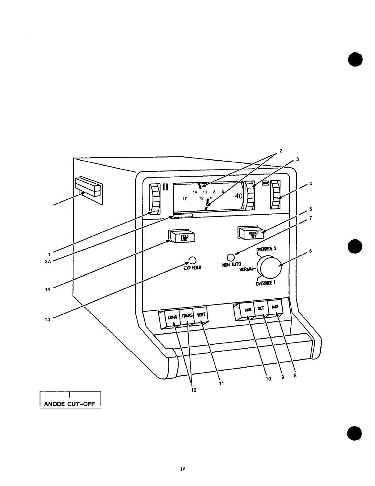
COLLIMATOR CONTROLS AND INDICATORS
15
1
SAMPLE
LABEL
3A
Page 6

GE MEDICAL SYSTEMS
REV
1
ADVANTX SENTRY THREE
AUTOMATIC COLLIMATOR OPERATION
DIRECTION
46-01
9403
SECTION
COLLIMATOR CONTROLS AND INDICATORS
1
Left thumbwheel prowdes for manual adjustment of longtudinal field size
(left to right dimension as
to increase field size
Upper pointer shows transverse field size, lower pointer shows longtudinal
field size
Field size scale selector
SID,
44 48
use
other
100
at the time the equipment
a Anode cut off warning label (location shown) indicates anode cut off
point at SID
tube targets
Right thumbwheel provides for manual adjustment
(front to back dimension as viewed from front of collimator) Rotate upward
to increase field size
Reduction on off button
manual reduction of field size while operating in the automatic mode (the
on' position) Depress the button a second time to restore
(the
off
pressing the button a second time The amber light flashes when in the
position
target tubes One has
cm, 110 cm
position) Replacing a cassette performs the same function as de
60
s
of
collimator) Rotate upward
-
Rotate thumbwheel to select scale for the desired
or
72" Two other scale combinations are furnished
of
120
cm and 150 cm scales Choice should be made
I
S
44'
or
less using a
-
After selecting
40 48
installed
14
60
and
"
x
17" cassette (wth 17
10" 11
of
SID
depress momentarily
72
"
and some 12
transverse field size
for
scales and the
'
to
permit
on
Key
Swtch - Has three positions
NORMAL
a
OVERRIDE
b
OVERRIDE
c
See Section
NON AUTO Indicator
is in the manual mode It flashes when the REDUCTION
is in the on position
Swtch marked AUX
tube suspensions
REO and must be depressed to couple the dewce It is most important that
this swtch
This swtch has a push-push type action That is the first push activates and
holds swtch in position, and the second push deactivates and releases swtch
See Notes
-
For
normal operation
1
-
For
use
when there
2
-
For
use when the collimator shutters
5
F
-
The amber light is steady
-
May be used
is
released when stereo work is completed
1
and 2
of
the collimator
is
a cassette size sensing malfunction
for
control
do
not respond
on
when the collimator
ON
OFF
of
compatible options On
is
marked STE
button
1
Page 7
GE MEDICAL SYSTEMS
REV
1
ADVANTX SENTRY THREE
AUTOMATIC COLLIMATOR OPERATION
DIRECTION
-
9
tion at a specific point usually when the focal spot is transversely centered
on tube hangers only and applies only when the transverse and vertical locks
On
are released
spare
equipment not havlng electrical detents
Depress when
it
is desired
to
stop transverse mo
40
46-01
This feature is
this swtch is a
9403
.
This swtch has a push
See Notes 1 and
10
late the tube unit about its
angulation lock this
This
depressed
See Notes
11
This swtch has a momentary type action (as described in Item
See Notes 1 and
12
moving
ond time to apply the locks (button out)
lock be applied to maintain the proper SID x ray beam horizontal
These
the tube unit long~tudinally
ANG
to
obtain the function described
1
and
-
push type action (as described in Item
2
-
Applicable to tube hangers and stands hawng an elec
on
the tube support Depress when
On
a spare
type
action That
2
-
Depress when movlng the tube unit vertically
2
LONG
and TRANS - Depress to release the locks when
or
transversely (laterally) Depress a sec
It
-
push action (as described
equipment wthout an electrical
is
is
important that the longtudinal
it
is desired to angu
the swtch must be held
in
item
8)
10)
8)
Note
Note
See Notes 1 and
1
2
Items
8,
9 10
Collimators for VRT Tables have different actions and different legends
than described here
rection
ating Manual)
Items
tor for
46-017201
8
9
10
11
11
2
and
For
46-017090
(VRT
and
12
2
12
for Models
description
Radiographic and Tomographic Table Oper
are not present
46 23371761
of
these swtches on the VRT Col
(VRT Table Operating Manual)
on
Model
and
46 23371861
46 19476561
or
Di
Collima
Page 8
GE MEDICAL
REV
1
SYSTEMS
ADVANTX SENTRY THREE
AUTOMATIC COLLIMATOR
DIRECTION
OPERATION
46-01
9403
ILLUSTRATION
2
Note
EXP
13
HOLD
Indicator - Red light
on
indicates x ray lockout because of
improper positioning of some element of the system such as the tube unit
Bucky stand
FIELD LIGHT
14
lates the x ray field at any gven collimator setting The light
seconds Time interval may be reduced by a senweman
Slot
for
15
added filters
a Model
46 23371761
button - Depress momentarily
to
obtain a light
field
stay on
if
so
desired
-
46 17709961 46 19475061, 46-19475063, 46 19476561
Collimator Extra Filtration of
1
2
or
3
mm
added
The collimator meets all regulatory requirements
tion The removable filtration (described above)
corporated in the Sentry collimator as a user option
a feature that was in
It
is prowded
that are interested in additional dose sawngs through additional hardening
of
the x-ray beam
As
additional aluminum filtration is added, contrast
decrease slightly
b Model
Mammography Collimator For technics below
until
way in a safety interlock prevents exposures about
46 17709861 46 19475561 46-19475562
49
it
hits the stop
For technics above
49
or
46 23371861
49
is not fully inserted
that simu
30 60
may be
for
sites
if
the filter
or
or
3
Page 9

GE
MEDICAL SYSTEMS
ADVANTX SENTRY THREE
AUTOMATIC COLLIMATOR OPERATION
REV
1
DIRECTION 46-
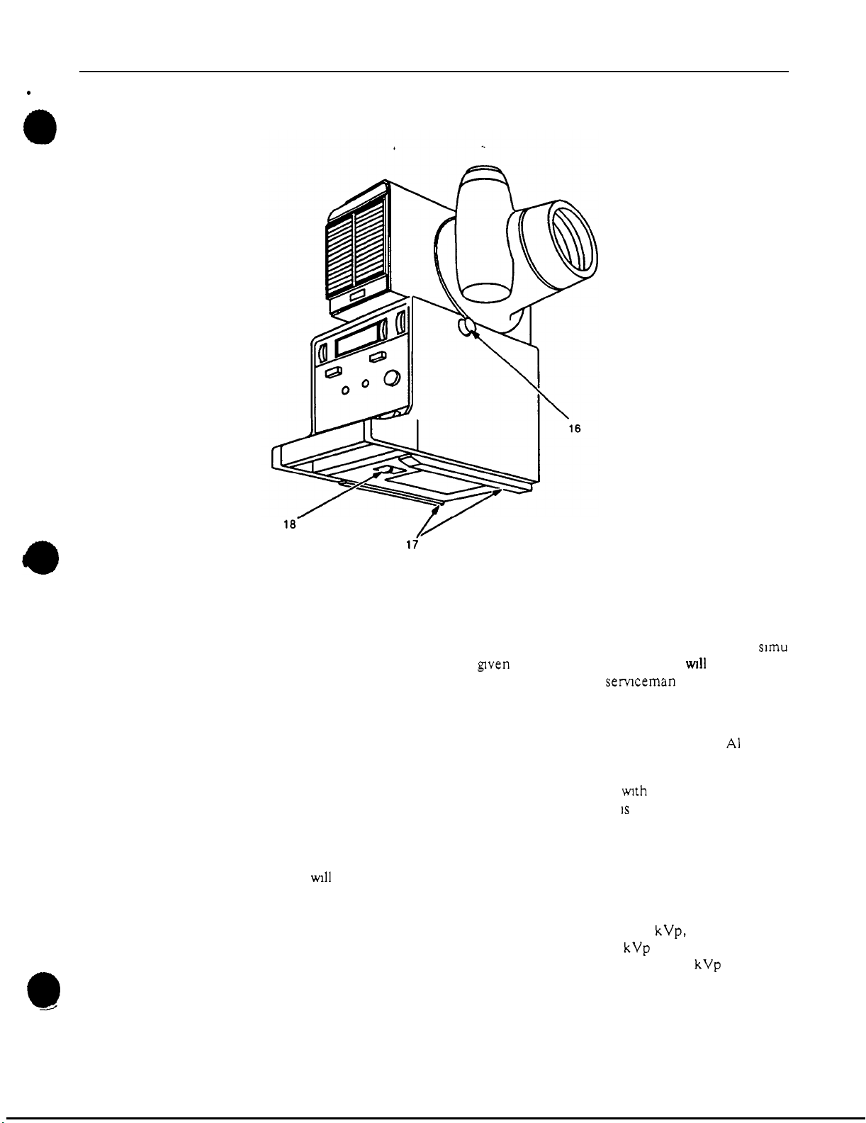
Rotation Detent Button - Depress button and rotate collimator until approxl
16
mate position desired
tor slightly until latch engages Detents are located at
and
from the front position
may be screwed in about
is
reached then release and continue to rotate collima
0
"
To
obtain more positive latching the button
3
turns Hence
be necessary
to
unscrew the
button before attempting rotation
-
Cone Tracks
17
snaps into slot on right track Press latch to release cone
Measuring Tape
18
ing on tape which corresponds to desired source
even
of
end
tape must be extended Tape has both an inch and centimeter scale
to measure
Slide cone into tracks from front of collimator until cone latch
for
removal
-
Extend tape to film plane and move collimator until mark
to
image distance
bottom of collimator housing For accurate measurements tab on
SID s up
to
79
"
(200
cm)
01 9403
(SID)
is
4
Page 10

GE
MEDICAL
REV
1
SYSTEMS
ADVANTX SENTRY THREE
AUTOMATIC COLLIMATOR OPERATION
DIRECTION
46-01
9403
ILLUSTRATION
CASSETTE
SIZE SENSING
CASSETTE MECHANISM
STAINLESS STEEL
CENTERING ADJUS
3
CASSETTE IN PLACE SWITCH,,
TRAY
TRAY HANDLE
AMPHENAL CONNECTOR
CLAMPING MECHANISM
CLAMPING MECHANISM
CLAMPING LOCK
SECTION
2
OPERATION
Centering
Centering Scale
OF
CASSETTE SIZE SENSING TRAY
To load a cassette pull the tray out
Activate the clamping mechanism by lifting the clamping lock See Illustration
Cassette Size Sensing Tray
Slide the clamping lock to permit inserting the cassette into the clamping mecha
The lock automatically centers the cassette lengthwse in the tray and se
nism
curely holds
it
Center the cassette wth either the centering scale
clamps
Push the clamping lock against the cassette and lock
In-Place swtch
Shelf
A
Centering Shelf is provided to assist you in positioning a cassette in a vertical
bucky The shelf conveniently located
Insert the shelf in the Centering Scale holes that correspond wth the cassette size
selected
in place
of
the bucky
on
the left is removable wth one hand
to
the tray stop
or
the centering notches in the
it
This activates the Cassette-
3
for
5
Page 11

GE MEDICAL SYSTEMS
ADVANTX
SENTRY
THREE
AUTOMATIC COLLIMATOR OPERATION
REV
1
Place the cassette on the shelf and center
it
DIRECTION
46-01
9403
of
the
centering Scale
The top of the cassette
example
also be at ten
if
the shelf is inserted in the ten
(10)
be in line wth the markings
on the scale
(10)
position - the top
on
the Centering Scale
of
the cassette
For
Push the Clamping Mechanism against the cassette and lock the Clamping Lock
Note
To prevent the locking handle from catching on the Bucky frame and poss
-
even
if
setting the tray in the Bucky
a cassette is not in the tray
Normally the tray does not have to be completely removed from the Bucky in order
to load a cassette In most instances cassettes may be inserted in the tray
by
the tray out until movement is stopped
Sufficient space is available for inserting
However
if
it
is desired to remove the tray from the Bucky pull the tray out until
the catch on the bottom
a
cassette when the tray is in this position
is stopped by the catch then press the catch against the tray bottom and hold
by
of
the tray
pulling
it
it
while sliding the tray from the Bucky
This tray has two cassette size sensors
-
one an arm bearing against the side
of
the
tray (senses longtudinal dimension) and the other connected to the rear cassette
clamp (senses transverse dimension)
Note
Be careful not to deform the sensing arm It
angular shape
obtaining accurate field limiting Should the arm become bent
replaced attempts should not
The tray must be insetted
all
this is not done the collimator
the
way
not transfer
be
made to straighten
into the Bucky to make electrical contact
to
the automatic mode
it
important in
it
must be
of
operation
If
6
Page 12

GE
MEDICAL
REV
1
SYSTEMS
ADVANTX SENTRY THREE
AUTOMATIC COLLIMATOR OPERATION
DIRECTION 46-
01
9403
SECTION
COLLIMATOR MODES
3
OF
OPERATION
OPERATING MODE KEY SWITCH FUNCTION INDICATOR
Automatic
Reduction
X
Ray Lock Out
Manual
System Failure
ON
NORMAL Position
OFF
NORMAL Position
OVERRIDE
OVERRIDE
1
Position*
2
Position*
Automatic limiting of the field size to the size of the NON
film Response to film size dimensions of
ches
Manual adjustment of the field size to an area smaller NON
than the film size provided Adjustment of field size to Light flashes
a size greater than
automatic mode) Field size automatically returns to
full
film size when the cassette
button is depressed a second time
Rad x-ray exposure
not proper or certain other equipment position
quirements not satisfied
details)
Manual adjustment of the field size over the
of blade travel provided
Cassette size sensing malfunction Permits manual NON-AUTO (Amber)
adjustment of the field size over the
travel
Permit hand
malfunction (See Illustration
-
driving
full
film
not
possible (while
IS
changed or when
not
possible because SID setting
(See
following section for
of
blades in case of collimator NON-AUTO (Amber)
7)
full
5
range
to
17
in- Light OFF
in
the
full
range NON-AUTO (Amber)
of
blade Light
-
AUTO (Amber)
-
AUTO (Amber)
EXP
HOLD (Red)
ON
Light
ON
Light ON
7
Page 13

GE MEDICAL SYSTEMS
REV
1
ADVANTX SENTRY THREE
AUTOMATIC COLLIMATOR OPERATION
DIRECTION 46-
01 9403
SECTION
CONDITIONS
SET-UP
Tube Unit over horizontal
table or Ven Bucky
Stand Bucky
Table at
chest
holder
Table
Table
System Failure
(A)
As conditions are met or not the system automatically switches from manual (NON-AUTO) or x-ray lockout
automatic mode and vice versa
(B) Selection of 3 SID
60
(or
is permitted from
(C)
Key
If
4
FOR
MODES
unit
cassette (film)
V
or
T
72
)
for automatic operation For Advantx systems using Release 12 x and later Applications software manual operation
switch in
table top is elevated x-ray lockout will occur if Conditions 2 3 and 4 have been met
or
T
s
for x ray beam horizontal technics made when equipment is installed usually these SID s are
OVERRIDE
OF
OPERATION
MODE (A)
Automatic
Manual
-
Ray
X
Lockout
Automatic
Manual
X
-
Ray
Lockout
Manual Not at preset SID positions
X-Ray
-
Ray
X
Override
Override 2
-
inch SID x-ray beam horizontal X-ray
1
and
CONDITIONS FOR MODE
1
Key switch in NORMAL position
2 Table or Bucky horizontal within
3 Cassette in tray tray in Bucky
-
ray beam veri
4 X
downward
5
Table top in lowest position
Stand Bucky
or at alt position above
6 SID36 ormore
Any one or more of conditions 2 3 4 and 6
violated
Key switch in NORMAL position
Condition
met (D)
1
Key switch
2 Table or Bucky vertical within
3 Cassette in tray tray
place
4
X
rected toward Bucky or film
5
Bucky Stand Bucky
right position
6 SID at preset value (B)
Any
lated
Condition
and/or Condition 6 violated with Conditions
2 3
At preset SID
Other conditions for auto mode operation
in manual mode
1
Conditions for auto mode apply except key
switch must be
Any Key Switch
2
positions
5
violated with Conditions 2 and 3
ray beam horizontal within
one or more of Conditions 2 3 and
5
does
not override x-ray lockout
within
19
5
from floor
in
NORMAL position
in
in
violated with Condition 3 met
in
OVERRIDE 1 position (C)
in
OVERRIDE2 position (C)
FUNCTION
Automatic Operation
10
"
directed
19
5
Manual Operation
Automatic Operation
Bucky or film in
di
-
or
from up
-
ray beam with-
is
locked out at all other SID s beam horizontal
-
Manual Operation
4
vio
-
No Rad X
sure Permitted
Manual Operation
No Rad X
sure Permitted
No Rad X
sure Permitted
Manual operation for
cassette size sensing
malfunction
Hand operation of
blades for collimator
drive malfunction
-
Ray Expo
-
Ray
-
Ray Expo
Expo
-
-
-
INDICATOR
Amber
Off
Red
Off
Amber On
Red
Off
Amber On
Red On
Amber
Off
Red
Off
Amber On
Red
Off
Amber On
Red On
Amber On
Red
Off
Amber On
Red On
Amber
Off
Red
On
Amber On
Red
Amber On
Red
Off
HOLD) to the
48
and
8
Page 14

GE
MEDICAL
REV
1
SECTION 5
OPERATING PROCEDURES
SYSTEMS
ADVANTX SENTRY THREE
AUTOMATIC COLLIMATOR OPERATION
DIRECTION 46-
01
9403
ILLUSTRATION
4
A
AUTOMATIC MODE - TABLE
4
I
I
X-RAY TABLE
-
VERTICAL
OR
BUCKY STAND, HORIZONTAL TECHNICS
BUCKY
STAND
Angulate the table or Stand Bucky to horizontal
Table top must be in its lowest position (if applicable) Bucky Stand must
5
"
be 19
Engage appropriate patient support devlces
Place loaded cassette in tray and insert the tray
See Section
Admit patient and position tube unit, beam vertical, directed downward
Use FIELD LIGHT to precisely center the tube unit over the point
Set
(Red) lights should be off
Position Bucky directly under the point of interest using FIELD LIGHT as
a guide Bucky centering light facilitates longtudinal alignment of focal spot
Select technic factors at x ray control make the exposure and remove the
cassette
*Check that there are no other cassettes or film in place in other dewces
'After setting the SID a smaller field size can
depressing the REDUCT
manually See Section 1, Item
from the floor (legs down) or at an alternate position above 19
all
the
way into the Bucky
2
for
SID
above
operation
36
"
At this point, the
of
the cassette size sensing tray
NON
AUTO (Amber) and EXP
If
this is not the case, refer to Section
be
obtained by momentarily
ON
OFF button and adjusting
5
The amber light should flash
the
collimator blades
of
5
"
interest
HOLD
4
9
Page 15

GE
MEDICAL SYSTEMS
REV
1
ILLUSTRATION
ADVANTX SENTRY THREE
AUTOMATIC COLLIMATOR OPERATION
DIRECTION
\
go+/-1
OR
180'
46-01 9403
I
I
X-RAY TABLE VERTICAL BUCKY STAND
B AUTOMATIC MODE - TABLE
1
Angulate the table to
Elevate Bucky
position
2
Place loaded cassette in tray and push tray
See Section 2 for operation of the cassette size sensing tray
3
Admit patient and adjust Bucky position to coincide wth the point
Secure patient
4
Align tube unit
The x ray tube unit must be positioned
of
was installed
4
OR
BUCKY STAND VERTICAL TECHNICS
90
"
vertical
to
approximate height required and engage patient support de
as
appropriate The Stand Bucky must be at the upright
or
Stand Bucky to
all
the
1
position
way
into the Bucky
of
if
any
so
the central x ray beam wll be wthin
from the horizontal, directed toward the Bucky Use the FIELD LIGHT
to
align laterally and longtudinally Set
the distances (such as 40 ' 48
-
must be greater than
or
60
)
selected at the time the equipment
36'
SID
or
interest
at one
At
this point, both
lights should be
5
Select technic factors at the x ray control make the exposure and remove
off
AUTO (Amber) and EXP HOLD (Red) indicator
If this is not the case
check Section
4
the cassette
'Check that there are no other casettes
'After setting the SID a smaller field size can be obtained
ON
depressing the REDUCT
manually
See Section
10
OFF button and adjusting the collimator blades
1,
Item 5 The amber light should flash
or
film in place in other dewces
by
momentarily
Page 16

GE
MEDICAL
REV
1
SYSTEMS
ADVANTX SENTRY THREE
AUTOMATIC COLLIMATOR OPERATION
DIRECTION 46
-
01
9403
ILLUSTRATION
CHEST
UNIT
6
n
CHEST
UNIT
AUTOMATIC MODE
C
-
WALL
MOUNTED CASSE’ITE HOLDERS
1
Place loaded cassette in holder or advance film to exposure area
Make sure there are no other cassettes in place in other devlces
2
Admit patient and adjust height of cassette
Secure patient support devlces as appropriate
3
Align tube unit wth cassette
The x ray tube unit must be positioned
from horizontal
and/or correlation height scales for lateral and vertical alignment wth the cas
the time the equipment was installed (such as
At this point both
lights should be
4
Select technic factors at the x ray control make the exposure and remove
the cassette or transport the film into the take up magazine
‘To obtain a
button and adjust the collimator blades manually See Section
amber light should flash
directed toward the cassette
NON
off
If
smaller
field size momentarily depress the REDUCT
or
AUTO
this is not the case, check Section
OR
OTHER CHEST UNITS
film and set
so
the x ray beam
(Amber) and
or
film holder
SID
be wthin
or
film Use the FIELD LIGHT
36”)
selected at
60
’
or
72
48
EXP
HOLD
’)
(Red) indicator
4
ON
1
Item
OFF
The
11
Page 17

GE MEDICAL SYSTEMS
D
MANUAL
MODE
OPERATION
ADVANTX SENTRY THREE
AUTOMATIC COLLIMATOR OPERATION
The manual mode of operation may be used for special technics
tem failure as indicated in Section
Summary of conditions one
the manual
1
No
tray in Bucky, tray in Bucky wth no cassette in place
(NON
AUTO)
or
mode amber light on
3
and 4 and Section
more
of
which
cause the collimator to go into
or
in case of sys
F
below
or
no film in expo
sure position
2
Tube unit positioned outside of
3
Table
or
Bucky outside of
4
SID less than
5
Key switch in OVERRIDE
Other than one
or
36
"
(x ray locked out at less than
more
of
1
or
the above exceptions the set up procedure is the same
limits from horizontal
limits from horizontal
20
2
positions
or
vertical
or
vertical
beam horizontal)
as for automatic mode operation Operate the collimator manually as follows
1
Verify positioning by using the FIELD LIGHT
2
Measure SID by using the measuring tape Reference Section 1 Item
Extend tab on end of tape and measure to film plane
top and add the distance to the film plane) Film plane
on the Monitrol Table is
3
Turn the FIELD SIZE SCALE SELECTOR to correspond wth the SID
2
5
on the Bucky Stand
(or
measure to table
-
table top distance
2
"
18
E
TOMOGRAPHY
F
SYSTEM FAILURE
1
Refer to Section
4
Turn the thumbwheels Section 1 Items 1 and
2
indicate the cassette size being used
Item 3 for explanation of this feature
4,
so
that the pointers Item
Check
Operate the system in the same manner as for the automatic mode The
requirement
excursion
1
If
correspond
RIDE
2
If the collimator blades do not respond in either manual
they can be operated
key swtch to OVERRIDE
This means
for
alignment of the x ray beam is automatically by passed during the
so
the collimator
stay in the automatic mode
the cassette size sensing feature malfunctions (failure
or
film size) turn the key swtch
1
position and operate in the manual mode per Section
2
position before using the screwdriver
of
Operating the Collimator should be used in
of
the light field to
to
the OVER
5
D
above
or
automatic mode
7
Turn the
case
Emergency only Excessive Hand Driving may result in Destruction
the Motor Drives within the Collimator Immediately call a GE Repre
sentative to obtain Service
'Call a GE representative to obtain service
of
of
12
Page 18

GE
MEDICAL
REV
1
SYSTEMS
ADVANTX SENTRY THREE
AUTOMATIC COLLIMATOR OPERATION
DIRECTION
46-01
9403
ILLUSTRATION
OPERATION WITH
PRY PLUG BUTTON
OUT WITH SCREWDRIVER
7
A
KEY
SWITCH IN OVERRIDE 2 POSITION
PRY
PLUG BUTTON
WITH
OUT
B
ENGAGE
GEAR AND TURN T-HANDLE HEX WRENCH
UNTIL DESIRED FIELD
T-HANDLE
HEX
WRENCH
IS
OBTAINED
I
N
SLOT
I
N
C
Refer
to
Illustration
collimator trim cover
Depress the rotational detent button and rotate the collimator
position Refer
of
the rear
the collimator Look into the opening In each cover and locate the
slotted gear (see Illustration
gear and turn the
Replace the plug buttons and rotate the collimator back
7 A and remove the plug button in the right side of the main
to
Illustration
T
handle hex wrench until the desired field coverage is obtained
7 B and remove the plug button in the trim cover on
7
C)
Engage a T handle hex wrench In the slot in each
90
"
from the front
to
the front position
13
Page 19

GE MEDICAL SYSTEMS
REV
1
ADVANTX SENTRY
AUTOMATIC COLLIMATOR OPERATION
DIRECTION
THREE
46-01
9403
e
SECTION
PRODUCT SPECIFICATIONS
6
A high intensity
illumination Distinct shadow crosshairs indicate the field center
ing light is
Full
prowded
angle tubes and
The collimator includes a handle for manipulation of the tube hanger
Tube hanger
front of the collimator
The collimator can be rotated and locked positively at
Response time for
seconds
Maximum rating of the diagnostic source assembly is
Model
46 23371761
of aluminum equivalent at
GE
A
Bucky center
to
aid in longtudinal focal spot Bucky alignment
17' x 17
"
radiographic coverage at a
15
"
for tubes
16
" x 16'
target angle
at
40
SID for
40'
source
(14' x 14
12
to
image distance (SID)
'
at
40
SID for
target angle tubes)
or
or
tube stand locks are controlled by the pushbutton swtches on the
from the front position
to
minimum openings and vlce versa is less than
150
46 17709961 46 19475061 46-19475063 46 19476561
Collimator Minimum inherent filtration
of
the collimator is
150
1
mm and/or 2 mm aluminum filters
11
target
tube stand
and
1
or
1
5
mm
is
5
Model
phy Collimator Minimum inherent filtration
num equivalent below
equivalent at
1
46 17709861 46 19475561 46-19475562
of
50
49
of
the collimator to
150
5
mm AI filter is not fully inserted This insures proper beam quality for radiogra
or
46 23371861
the collimator
1
5
Mammogra
is 0 1
mm of alumi
1
6
mm of aluminum
49
if
the
phy at each
The nameplate bearing equipment model number and serial number is located on
the lower rear of the collimator
The cassette tray contains
5
"
x
7
"
to
cassettes from
Cassettes must meet ASA specification
1-1/8
'
greater in length and wdth than the film)
14 x 17'
PH
3
21 1957
(The cassette must be
14
Page 20

GE
MEDICAL SYSTEMS
REV
1
ADVANTX SENTRY THREE
AUTOMATIC COLLIMATOR OPERATION
DIRECTION
46-01 9403
SECTION
X
RAY
TUBE UNIT HOUSING COMPATIBILITY
7
For
compatibility data, see the system pre installation manual
for
the system being
installed or modified Refer to Sentry Three Automatic Collimator Planning Direc
46-017 158
tion
Section 2 Compatibility
Page 21

GE MEDICAL SYSTEMS
REV
1
ADVANTX SENTRY THREE
AUTOMATIC COLLIMATOR OPERATION
DIRECTION
46-01
9403
SECTION
8
SERVICE
Preventive Maintenance
Note
Qualified Service
In order to assure continued safe performance of this x ray equipment a preven
tive maintenance program must
supply
or
arrange for this semce
be
established It is the owner s responsibility to
Maintenance procedures for the Sentry Three Automatic Collimator are required
of
three months after completion
These maintenance procedures are described in Chapter
rection
46-0
194
19
Advantx PM Schedules available from representatives of GE
installation and every six months thereafter
4
of Sentry Three Auto
46-001414
(SM
and in Di
Medical Systems
A
maintenance check list PMS Data Record - Sentry Three Automatic Collima
tor is a guide
to
typical maintenance tasks It is provided as the last five pages
of
this operation manual (This PMS Data Record was formerly called Form
Before filling out the PMS Data Record make copies
of
it
for future use
Safe equipment performance also requires the use of
trained on medical x ray apparatus
GE
Medical Systems and its associates main
tain a world
obtained If desired arrangements can usually be made to have preventive and/or
emergency
to discuss this plan
User Service and Maintenance
Cleanliness is a prime rule in maintaining equipment At least once a month exter
foreign material that may have accumulated
kind as they may dull the finish
paste wax Do not use a wax containing a cleaning substance Do not use wax on the
dial
General Electric x ray equipment contains operation safeguards to ensure maw
mum safety Aside from routine maintenance any abnormal noise
unusual performance should be reponed immediately
representative Before calling for
operated in accordance
or
light field wndow
Do
not use cleaners or solvents
or
blur the lettering Polish wth PURE liquid
to
a GE Medical Systems
of
any
or
16
Page 22

GE
MEDICAL
REV
1
PMS DATA RECORD
SYSTEMS
ADVANTX SENTRY THREE
AUTOMATIC COLLIMATOR
DIRECTION
OPERATION
46-01
9403
Page 1 of
5
DATE
OF
INSPECTION
MODEL AND SERIAL NUMBER Collimator
Use this form in conjunction
OK
,
descriptive words such as
Adjusted Lubed’
indicated
A
MAINTENANCE
1
Cleaning and lubrication
-
COLLIMATOR
a Ends of movlng shafts
b Blade pivot points
c Ball and socket joint
d Pulleys gears and bushings
e Pointer tracks
2
Inspection
a Interface
(1)
Mounting screw tightness
(2)
Interface plate condition
or
N/A
if
not applicable Enter measurements made
if
so
b Steel drive cables
(1)
Condition
(2)
Tension
of
Tightness
c
screws and other
assembly hardware
Electrical connectors and harness leads
d
(1)
Condition
(2)
Cleanliness
e
Dress away
parts and light
from
box
of
light field wndow
and mirror
f
Engagement
of
blade drive
motor output gears
g Adjust drive spring cable
tension
if
necessary
List test equipment used,
PMS PERFORMED
BY
This record should be filed in room wth x ray room log form No
17
This page may be copied permission has
been granted
by
the General Electric
Co
Page 23

GE MEDICAL SYSTEMS
REV
1
B
MAINTENANCE
1
Inspection
-
a Tray plug and Bucky receptacle
(1) Condition
(2)
‘Float” freely in the horizontal
and vertical directions
binding
Bucky pin and pad assembly
b
(1)
Condition
(2)
Floats
freely in the horizontal
direction
c Condition of gears pulleys, sensing
arm steel cables and pots inside
mechanism compartment
2
Cleaning
Contact surfaces of tray plug and
a
Bucky receptacle
b Inside of mechanism compartment
3
Lubrication
Tray plug contact surfaces
a
spray lubricant)
(WD
40
ADVANTX SENTRY THREE
AUTOMATIC COLLIMATOR OPERATION
DIRECTION
46-01
9403
In general, moving parts of the cassette
tray should not require lubrication during
the life of the tray
C
FUNCTIONAL
1
Functional Performance
a Table horizontal techniques
Techniques involwng an
b
c Off table radiography involwng
Vertical Bucky Stand
Off table radiography involwng
d
17”
2
Field Light Operation
a Field light
Light field quality (uniform bright
b
ness sharply defined edges)
c Voltage across lamp’ VAC
3
Film quality (uniform density, no radiation
cut
off
not excessive)
CHECKS
image receptor size chest unit
‘
on” time interval sec
sharply defined edges penumbra
14
‘
x
18
This page may be copied permission has
been granted by the General Electric
Co
Page 24

GE
MEDICAL
REV
1
4
Alignment
SYSTEMS
and
Field
AUTO RAD COLLIMATOR-TO-TABLE BUCKY
ADVANTX SENTRY THREE
AUTOMATIC COLLIMATOR OPERATION
DIRECTION
46-01
Page
3
9403
of 5
SOURCE - RECEPTOR
CONFIGURATION
Beam Angulation
Indicated
Actual
Error
CENTER
LIGHT
TO
X-RAY
SIZE
NDICATOR
Error
Incheslcm
Total
I
Total Lat
Total
Incheslcm
Total Long
Indicated
Lat
Long Inches/cm
Long
Lat
Long
I
I
OVERHEAD MOUNTED TUBE UNIT
Vert
(1
8%
8%
J
MIN
I
TABLE IMAGE RECEPTOR
SID
MAX
t
I
I
Vert
MAX
SID
SIZE
SIZE
on both
All
calculabons must
Film Size
Measured
Field Size
Incheslcm
Lat
Long Incheslcm
Long,
Total
SS
and LS document worst case
be
in inches
or
I
cm
10 x12
I
19
14
I
8%
man
8%
This
page may
been granted
be
copied permission has
by
the General Electric
Co
Page 25

GE MEDICAL SYSTEMS
ADVANTX SENTRY THREE
AUTOMATIC COLLIMATOR OPERATION
REV
1
4
Alignment and Field Sizing (Continued)'
AUTO RAD COLLIMATOR TO CHEST UNIT
SOURCE - RECEPTOR
I
SID
TO
CENTER
LIGHT
TO
X-RAY
I
CON FI GU
Beam Angulation
Indicated
Actual
Error
Error
Total Lat
Total Lat %SID
I
Long
I
(1
(1
7%
8%
8%
OR
VBS
OVERHEAD MOUNTED TUBE UNIT
DIRECTION
TABLE IMAGE RECEPTOR
SID
2
46-01
Vert
.
9403
FIELD SIZE Indicated
INDICATOR
I
I
I
SIZE
.
-
SIZE
I
I
I
(1)
NOTE
Do
All
calculabons must
Lat
Long Incheskm
I
Film
Measured
Field
Long Incheskm
Long
Total
not repeat
be
Size
already
in inches or crn
Size
performed
I
(1
8%
7%
I
I
on previous
I
I
page
10
X12
I
I
14 x17
I
'
-
I
I
I
I I
I
I
8%
8%
8%
20
This page may be copied permission has
been granted by the General Electric Co
Page 26

ADVANTX SENTRY THREE
GE MEDICAL
4
REV
1
5
Blade Response
SYSTEMS
AUTOMATIC COLLIMATOR OPERATION
DIRECTION 46-
Page
01
9403
5
of 5
a Damping
b
Smoothness
of
operation
c SID Compensation
6
Alignment
7
Operation of Filter Interlock
Extension Cylinder
-
or
Cone
Mammography Collimator
8
Collimator Rotation
of
a Smoothness
operation
b Detent action
c
9
Cassette Size Sensing Tray
-
Cassette Clamping
a Cassette clamp alignment
b
Clamping force
10
Beam Quality - Half Value Layer of
Useful
System Field Tests
for
HHS
46-01 3894,
Compliance
)
mm
*Results must also be recorded on Data Record Form
“Data Record for HHS Field Tests”
21
This page may
been granted
be
copied permission has
by
the General Electric
Co
 Loading...