

Page 1

GE Fanuc Automation
Series 90™-70
CPU Redundancy User' s Guide
Programmable Cont rol Products
Enhanced Hot Standby
GFK-1527A May 2000
Page 2

Warnings, Cautions, and Notes
as Used in this Publication
Warning notices are used in this publication to emphasize that hazardous voltages,
currents, temperatures, or other conditions that could cause personal injury exist in this
equipment or may be associate d with its use.
In situations where inattention could cause either personal injury or damage to
equipment, a Warning notice is used.
Caution notices are used where equipment might be damaged if care is not taken.
Notes merely call attention to information that is especially significant to understanding and
operating the equipment.
GFL-002
Warning
Caution
Note
This document is based on information available at the time of its publication. While efforts
have been made to be accurate, the information contained herein does not purport to cover all
details or variations in hardware or software, nor to provide for every possible contingency in
connection with installation, operation, or maintenance. Features may be described herein
which are not present in all hardware and software systems. GE Fanuc Automation assumes no
obligation of notice to holders of this document with respect to changes subsequently made.
GE Fanuc Automation makes no representation or warranty, expressed, implied, or statutory
with respect to, and assumes no responsibility for the accuracy, completeness, sufficiency, or
usefulness of the information contained herein. No warranties of merchantability or fitness for
purpose shall apply.
The following are trademarks of GE Fanuc Automation North America, Inc.
Alarm Master Genius PROMACRO Series Six
CIMPLICITY Helpmate PowerMotion Series Three
CIM P LIC IT Y 90 – ADS Logicm aster PowerTRA C VersaMax
CIMSTAR Modelmaster Series 90 VersaPro
Field Control Motion Mate Series Five VuMaster
GEnet ProL oop Series One Workm aster
©Copyr ight 1998 - 2 000 GE Fanuc Autom ation N orth Am erica, In c.
All Rights Reserved .
Page 3

This manual is a reference to the hardware components, configuration and operation of Enhanced
Hot Standby CPU Redundancy for the Series 90-70 Programmable Logic Controller. This revision
adds information about new redundancy CPUs IC697CGR772 and IC697CGR935, as well as new
features available with Release 7.85 of the product. Also, corrections have been made where
necessary.
The information in this manual is intended to supplement the information contained in the system
installation, programming, and configuration information found in the manuals listed below under
Related Publications.
Content of This Ma nual
Chapter 1. Introduction: introduces a method of CPU Redundancy for the Series 90-70
Programmable Logic Controller, which is referred to as Enhanced Hot Standby CPU Redundancy.
Preface
Chapter 2. System Components: describes th e h ar d wa re compon en ts for an Enhanced Hot
Standby CPU Redundancy system.
Chapter 3. Configuration Requirements: defines the special configuration requirements of an
Enhanced Hot Standby CPU Redundancy system.
Chapter 4. Normal Operation: describes the operation of an Enhanced Hot Standby CPU
Redundancy system.
Chapter 5. Fault Detection: describes how faults are handled in an Enhanced Hot Standby CPU
Redundancy system.
Appendix A. Cabling: provides a description and diagram of the Series 90-70 multidrop cable for
use in redundancy systems.
Relat e d Publi ca t ions
For more information, refer to these publications:
Genius I/O System User' s Manual (GEK-90486-1). Reference manual for system designers,
programmers, and others involved in integrating Genius I/O products in a PLC or host co mputer
environ ment. This book provides a syste m overvie w, and describes t he type s of syst ems that can be
created using Genius products. Datagrams, Global Data, and data formats are defined.
Genius Discrete and Analo g Bl ocks User' s Ma nual (GEK-90486-2). Reference manual for system
designers, operators, mai ntenance pe rso nnel, a nd others usi ng Genius disc rete a nd analog I/O
blocks. This book contains a detailed description, specifications, installation instructions, and
conf i gura tion i nstructions for dis cre t e a nd an alo g blocks .
Series 90-70 PLC Installation Manual (GFK-0262). This book describes the hardware
components in a Series 90-70 PLC system, and provides the details of system installation.
GFK-1527A iii
Page 4

Preface
Logicmaster 90-70 Programming Software User's Manual (GFK-0263). A programming software
user's manual for system operators and others using the Logicmaster 90-70 software to program,
configure, monitor, or control a Series 90-70 PLC system.
Series 90-70 PLC CPU Instruction Set Reference Manual (GFK-0265). Reference manual which
describes operation, fault handling, and programming instructions for the Series 90-70 PLC.
Series 90-70 System Manual for Control Software Users (GFK-1192). Provides an overview of
hardware and software features of the Series 90-70 PLC.
Series 90-70 Remote I/O Scanner User's Manual (GFK-0579). Reference manual for the Remote
I/O Scanner, which interfaces a drop containing Series 90-70 modules to a Genius bus. Any CPU
capable of controlling t he bus can be used as the hos t. This book d e s c ribes the Re mote I /O Scanner
features, configuration, and operation.
Series 90-70 Bus Controller User's Manual (GFK-0398). Reference manual for the bus
controller, which interfaces a Genius bus to a Series 90-70 PLC. This manual describes the
ins tallation and op erat ion of the Bus Controller. It also contai ns the progr am min g infor m ation
needed to interface Genius I/O devices to a S er ies 90-70 P LC.
Control User’s Gui de (GFK-1295). Describes configuration and programming software using
Control Programming. Control software, release 2.1 or later is required to configure Ethernet
Global Data as described in this manual.
iv Series 90™-70 Enhanced Hot Standby CPU Redundancy User's Guide–May 2000 GFK-1527A
Page 5

Contents
Chapter 1 Introduction..................................................................................................... 1-1
Enhanced Hot Standby CPU Redundancy.....................................................................1-2
Features of Enhanced Hot Standby CPU Redundancy...................................................1-3
Using the Redundancy CPU for Non-Redundant Operation ....................................1-3
Compatibility with CPU780...................................................................................1-3
Redundancy CPUs as Compared to Other Series 90-70 CPUs.......................................1-4
Features not Available with Redundancy CPUs......................................................1-4
Differences in Operation for Redundancy CPUs.....................................................1-4
Components of the Enhanced Hot Standby Redundancy System...................................1-5
Enhanced Redundancy CPU Module......................................................................1-5
Redundancy Communications Module....................................................................1-5
Redundant Racks....................................................................................................1-5
I/O Systems for Enhanced Hot Standby CPU Redundancy......................................1-5
Genius I/O............................................................................................................1-6
Local I/O..............................................................................................................1-6
Cable Connections................................................................................................1-6
Enhanced Hot Standby CPU Redundancy System with Local I/O ..........................1-7
Control Strategies.........................................................................................................1-8
GHS Control Strategy........................................................................................... 1-8
GDB Control Strategy...........................................................................................1-8
Basic Enhanced Hot Standby Operation ........................................................................1-9
Output Control with GHS......................................................................................1-9
Output Control with GDB.....................................................................................1-9
Basic CPU Redundancy Setups...................................................................................1-10
Single Bus with Preferred Master: GHS Control Strategy.....................................1-10
Single Bus with Floating Master: GDB Control Strategy......................................1-11
Dual Bus with Floating Master: GDB Control Strategy........................................ 1-12
Duplex CPU Redundancy.................................................................................... 1-13
Online Programming...................................................................................................1-13
On-Line Repair...........................................................................................................1-13
Chapter 2 System Components........................................................................................ 2-1
System Racks...............................................................................................................2-1
Redundancy CPU.........................................................................................................2-2
Features................................................................................................................2-2
CPU Architecture .........................................................................................................2-3
Expansion Memory Board.....................................................................................2-3
Watchdog Timer...................................................................................................2-3
CPU Features ...............................................................................................................2-4
Memory Protect Keyswitch...................................................................................2-4
CPU LEDs............................................................................................................2-4
Battery Connectors................................................................................................2-4
CPU Mode Switch................................................................................................2-5
Run/Outputs Enabled Mode............................................................................2-5
Run/Outputs Disabled Mode...........................................................................2-5
Stop Mode .....................................................................................................2-5
Port 1....................................................................................................................2-5
GFK-1527A v
Page 6

Contents
Port 2....................................................................................................................2-5
Port 3....................................................................................................................2-5
Redundancy Communications Module..........................................................................2-6
Unit Select Pushbutton.......................................................................................... 2-6
Connector............................................................................................................. 2-7
RCM Status LEDS................................................................................................2-7
Bus Transmitter Module...............................................................................................2-8
Connectors............................................................................................................2-8
Bus Transmitter Module Status LEDs....................................................................2-8
Bus Receiver Module....................................................................................................2-9
Connectors............................................................................................................2-9
Cables and Termination ........................................................................................2-9
Genius Bus Controller ................................................................................................ 2-10
Location of GBCs and Blocks .............................................................................2-10
Single Bus Genius Networks ............................................................................... 2-11
Dual Bus Genius Networks .................................................................................2-11
Connectors..........................................................................................................2-12
Bus Controller LEDs...........................................................................................2-12
Chapter 3 Configuration Requirements.......................................................................... 3-1
Programmer Connection for Configuration...................................................................3-1
One Application Program in Both PLCs........................................................................3-1
Program Folders in Control Programming Software...............................................3-1
Program Folders in Logicmaster 90.......................................................................3-2
CPU Configuration Parameters.....................................................................................3-2
Configuring Shared I/O References ........................................................................ 3-3
Finding the Memory Available for Application Program Storage............................3-4
System Communications Window Considerations ..................................................3-4
Configuring the Redundancy CPU for Non-redundant Operation..................................3-5
Rack Module Configuration Parameters........................................................................3-5
Bus Controller Configuration Parameters......................................................................3-5
Genius I/O Block Configuration Parameters..................................................................3-6
Chapter 4 Normal Operation........................................................................................... 4-1
Powerup of a Redundant CPU.......................................................................................4-2
Incompatible Configurations.........................................................................................4-3
Resynchronization of a Redundant CPU........................................................................4-3
GHS Control Strategy...................................................................................................4-4
GDB Control Strategy................................................................................................... 4-4
%S References for CPU Redundancy............................................................................4-5
OVR_PRE %S Reference Not Available...............................................................4-5
Scan Synchronization...................................................................................................4-6
Input Data and Synchronization Data Transfer to the Backup Unit................................4-6
Sweep Time Synchronization................................................................................4-6
Output Data Transfer to the Backup Unit......................................................................4-7
Data Transfer Time.......................................................................................................4-8
vi Series 90™-70 Enhanced Hot Standby CPU Redundancy User's Guide–May 2000 GFK-1527A
Page 7

Contents
Fail Wait Time......................................................................................................4-8
Programming a Data Transfer from Backup Unit to Active Unit..................................4-10
Data Transfer Example................................................................................. 4-10
Disabling Data Transfer Copy in Backup Unit (SVCREQ #43)...................................4-11
Command Block for SVCREQ #43..................................................................... 4-12
Backup Qualification with SVCREQ #43............................................................4-13
Validating the Backup PLC's Input Scan ............................................................. 4-13
Validating the Backup PLC's Logic Solution....................................................... 4-13
Switching Control to the Backup Unit.........................................................................4-14
Switching Times ................................................................................................. 4-14
Commanding a Role Switch from the Application Program (SVCREQ #26)........4-14
Example.......................................................................................................4-14
RUN Disabled Mode..................................................................................................4-15
RUN Disabled Mode for GHS Control Strategy....................................................4-15
Example 1: Role switches allowed on both units.................................................. 4-15
Example 2: Role switches allowed on both units.................................................. 4-16
Example 3: Role switches not allowed on either unit............................................4-16
Example 4: Role switches allowed on both units.................................................. 4-16
Example 5: Role switches allowed on both units Secondary Unit Active.............. 4-17
Example 6: Role switches not allowed on either unit, Secondary Unit Active.......4-17
Example 7: Role switches allowed on both units, Secondary Unit Active............. 4-17
Example 8: Invalid..............................................................................................4-18
RUN Disabled Mode for GDB Control Strategy...................................................4-18
Background User Checksum and Background Window Timing Instructions................4-19
Finding the Words to Checksum Each Sweep...................................................... 4-19
Finding the Background Window Time...............................................................4-20
Finding the Total Sweep Time.............................................................................4-20
Miscellaneous Operation Information.........................................................................4-21
Timer and PID Function Blocks.......................................................................... 4-21
Timed Contacts...................................................................................................4-21
Multiple I/O Scan Sets........................................................................................4-21
C Debugger ........................................................................................................4-22
STOP to RUN Mode Transition ..........................................................................4-22
Background Window Time.................................................................................4-22
Sequential Function Chart Programming (SFC)...................................................4-22
Genius Bus Controller Switching................................................................................4-23
Ethernet Global Data in a Redundancy CPU............................................................... 4-24
Ethernet Global Data Consumption..................................................................... 4-24
Ethernet Global Data Production.........................................................................4-25
SNTP Timestamping...........................................................................................4-25
Chapter 5 Fault Detection................................................................................................ 5-1
Configuration of Fault Actions......................................................................................5-1
Fault Detection.............................................................................................................5-2
PLC Fault Table Messages for Redundancy..................................................................5-3
Fault Response .............................................................................................................5-5
Faulting RCMs, Losing Links, and Terminating Communications.................................5-6
Faulting the Redundancy Communications Module...............................................5-6
Losing a Link........................................................................................................5-6
GFK-1527A Contents vii
Page 8

Contents
Fault Actions in a CPU Redundancy System.................................................................5-7
Configurable Faults...............................................................................................5-8
Non-Configurable Fault Group..............................................................................5-9
Fatal Faults on Both Units in the Same Sweep.......................................................5-9
On-Line Repair...........................................................................................................5-10
Maintaining Parallel Bus Termination...................................................................5-11
On-Line Repair Recommendations....................................................................... 5-11
Power Supply.......................................................................................................5-11
Racks...................................................................................................................5-11
Central Processor Unit..........................................................................................5-12
Redundancy Communications Module and Cables................................................5-12
Redundancy Communications Link Failures.........................................................5-12
Bus Transmitter Module.......................................................................................5-13
Genius Bus Controller..........................................................................................5-13
Genius Bus ........................................................................................................... 5-13
Single Bus Networks Bus faults .......................................................................... 5-13
Dual Bus Networks ............................................................................................. 5-14
Genius Blocks......................................................................................................5-14
Appendix A Cabling Information .......................................................................................A-1
IC690CBL714A Multi-drop Cable............................................................................... A-1
Purpose.................................................................................................................A-1
Specifications........................................................................................................ A-1
viii Series 90™-70 Enhanced Hot Standby CPU Redundancy User's Guide–May 2000 GFK-1527A
Page 9

Chapter
Introduction
1
This chapter introduces the method of CPU Redundancy for the Series 90-70 Programmable Logic
Controller, which is referred to as Enhanced Hot Standby CPU Redundancy. The contents of this
chapter describe:
Enhanced Hot Standby CPU Redundancy
Components of the Enhanced Hot Standby Redundancy System
Control Strategies
Basic Enhanced Hot Standby Operation
Basic CPU Redundancy Systems
Definition of Terms
Active Unit
Backup Unit
CPU Redundancy
Critical Component
Hot Standby
Primary Unit
Redundancy
Secondary Unit
Synchronized
Dual Bus
Local System
Remote System
The unit that is currently contr oll in g the pr o cess .
That unit that is synchron ized with the active unit and able to take over the process.
A system with two PLC CPU units cooperating to control the same process.
A component whose failure causes the PLC (either active o r b ac kup) where it res ides to stop.
A featu re of Ge ni us devi c e s w hereb y the device pre f ers outp u t da t a from the Bus Cont roller at Ser i a l Bus
Address 31. When outputs from that Bus Contr oller are not avai lable, the devi ce takes output data from the
Bus Contro ller at Serial B us Address 30. If outputs from neither Controlle r are available, the device places its
outputs in the designate d default state .
The unit in which the externally redundant Bus Controllers' Serial Bus Address is 31.
The us e of multi ple ele m ents control ling th e same proces s to provid e alterna te fun ct ional channels in case of
failure.
The unit in which the externally redundant Bus Controllers' Serial Bus Address is 30.
A unit is considered to be synchronized when it has received the latest status information from the Active unit
and is running the PLC program in parallel.
The use of two Genius busses to control the same I/O devices. The busses are linked to the I/O devices by one
or more Bus Switch ing Modu les (BSMs) . A BSM will automatically switch to the other bus if the active bus
has a failure.
(LE Ds on RCM) - The system where the RCM resides. LEDs indicate whethe r the lo cal u n it is ready to
become the active unit or is the act ive unit in a redundancy system.
(LEDs on RCM) - The system to which the RCM is connected via the communications cable. LEDs indicate
whethe r the remote unit is ready to become the active unit or is th e active unit in a red undancy system.
GFK-1527A 1-1
Page 10

1
Enhanced Hot Standby CPU Redundancy
CPU Redundancy allows a critical application or process to continue operating if a failure occurs in
any sin g le component. An Enhanced Hot Stand by CP U Redundan cy syst em consis ts of two CPUs
conn ected to one or more Geniu s I/ O networks. One P LC is the Primary PLC and the other is the
Secondary PLC. The Primary PLC contains all externally redundant Genius Bus Controllers at
Seri al Bus Addres s 31 ; the Secondary PLC contains all externall y r ed undant Genius Bus
Controllers at Serial Bus Address 30.
Each PLC
Redundancy Communications module and a Bus Transmitter Module
Communications module provides the synchronizing link between the two units. The scanning
process of both CPUs is synchronized to minimize bumpless switching from one PLC to the other.
The CPU that currently controls the system is called the active unit, the other CPU is the backup
unit. Control automatically switches to the backup unit if certain system failures are detected in the
active unit. Control can also be switched manually by pressing a pushbutton on the Redundancy
Communications Module, or through the application program. When a manual switch of control
occurs, the CPUs switch roles; the active unit becomes the backup unit and the backup unit
becomes active.
The system runs synchronously with a transfer of all control data that defines machine status and
any in ternal data n eeded to keep the two CPUs operating in s ync. The transfer of data from the
acti ve un it to the standby unit occurs twice per sweep. These CPU to CPU tr ansfers ar e checked
for data integrity.
must have a Redundancy CPU module (IC697CGR772 or IC697CGR935), a
. The Redundancy
1-2 Series 90™-70 Enhanced Hot Standby CPU Redundancy User's Guide – May 2000 GFK-1527A
Page 11

Features of Enhanced Hot Standby CPU R edundancy
Bumpless switching
Synchronized CPUs
4.7 ms (CGR935), 5.9 ms (CGR772) base sweep time in Run mode
One scan switching (in most ca ses)
Configurable backup data size
No single point of failure (excluding Genius I/O blocks and bus stubs)
Redundant backup communications
Online repair of failed component
Onl i ne pr ogramming
Same or di ff erent programs in Primary and S econdary uni ts
Redundancy Communications Module
Manual pushbutton for switching control between active and backup CPUs
Five Status LEDs
1
Status Bits (%S) reflect redundancy status of Primary/Secondary units
Program control switching
Memory parity and checksums
Common I/O on Genius bus
Genius Dual Bus support
Background Diagnostics
Memory Protect Keyswitch
Using the Redundancy CPU for Non-Redundant Operation
The Redundancy CPU can be used for both redundant and non-redundant applications. The
functionality and performance of a Redundancy CPU configured for standalone operation is the
same as for a unit that is configured for redundant operation which has no backup currently
available. This includes the redundancy informational messages such as those generated when a
unit goes to Run mode. Refer to Chapter 3, "Configuring the Redundancy CPU for Non-redundant
Operation."
Compatibility with CPU780
Note that the IC697CGR772 is not compatible with the CPU780. Also, mixing of IC697CGR935
and IC697CGR772 CPUs is not allowed in the same redundant system, since there are several
differences betw een the t wo models.
GFK-1527A Chapter 1 Introduction 1-3
Page 12

1
Redundancy CPUs as Compared to Other Series 90-70 CPUs
The Redundancy CPU has several differences in operation compared to other Series 90-70 CPUs.
Features not Available with Redundancy CPUs
The following features are not available:
I/O Interrupts:
modules, the high alarm and low alarm interrupts from the analog input modules, and
interrupts from third party VME modules. A program that declares I/O Interrupt triggers
cannot be store d to a Red undancy CP U.
Timed Interrupts
VME Integrator Racks.
This includes the single edge triggered interrupts from the discrete input
Stop I/O Scan mode:
the sel ection and r eturn an error .
Flash operation: User Flash (Store/Load, Verify) as opposed to Flash firmware upgrade
FBCs and FIP I/O
Timed and Event-triggered Programs:
cannot be store d.
Microcycle Mode and Periodic Programs
14-point interrupt module
OVR_PRE %S reference which indicates whether one or more overrides is active
If an attempt is made to place the PLC in this mode, the PLC will reject
Differences in Operation for Redundancy CPUs
The following features operate differently with the CGR772 or CGR935 than they do with other
Series 90-70 CPUs:
RUN/DISABLED mode. This is explained in chapter 4,
Configuration of Fault Actions
STOP to RUN mode transition
Background Window Time (default is different)
Logic that contains Timed or Event-triggered programs
Operation
.
C Debugger
Ethernet Global Data operation is enhanced
Rack 7 is not available
1-4 Series 90™-70 Enhanced Hot Standby CPU Redundancy User's Guide – May 2000 GFK-1527A
Page 13

Components of the Enhanced Hot Standby Redundancy System
Enhanced Redundancy CPU Module
To utilize the features described in this manual, an Enhanced Redundancy CPU Module
(IC697CGR935 or IC697CGR772) must be installed rack 0, slot 1 of both the Primary and
Second ary PLCs. Fea tures of the redundancy CPU that ar e different from conven tional C P US are
listed on the previous page.
Redundancy Co mmunications Modul e
Two Redundancy Communications Modules (RCM) are available that provide a path for sharing
data between the two CPUs in the redundant system. Catalog number IC697RCM711 is for use in
standard Series 90-70 racks and IC687R CM 711, whic h is for use in dual redundant racks
(described below).
The RCM module has a pushbutton switch that can be used to manually switch control from the
active unit to the backup unit. The switch between units can also be controlled through the
application p ro g ram logic.
1
In a synchronized system, I/O data is controlled by only one unit (the active unit) but is shared
between both units (active and backup units). The Redundancy Communications Module provides
a communications path to synchronize the two CPUs. It also provides the communications path for
the transfer of I/ O da ta. An RCM must be located in th e main rack of both the Primar y PLC and
the Secon dary PLC, or in both sections of a dua l r edundant r ack.
Redundant Ra ck s
Redundant racks; IC697CHS770 (rear mount) and IC697CHS771 (front mount) have two power
supply slots and 12 backplane slots divided into two separate sections, each having a power supply
slot and 6 backplane slots. The redundant rack is designed for easy integration of third-party VME
modules into a Series 90-70 PLC system. These racks accept all standar d Ser ies 90-70 modules
and ½ slot VME mod u les. VME modul es r eq uire 0.8” spa cing and use one slot, while standard
Series 90-70 modules use two of the available slots. Cable connection between the required ½ slot
RCM modules and the required ½ slot BTM modules (catalog number IC687BEM713) in a
redundant rack is through an available 3 foot (0.9 meter) cable, IC697CBL803.
I/O Systems for Enhanced Hot Standby CPU Redundancy
Both Series 90-70 Local I/O and Genius I/O systems can be present in an Enhanced Hot Standby
CPU Redundancy system. The two PLCs need not have matching I/O systems -- they may have
different numbers of I/O racks, different I/O modules and different option modules.
GFK-1527A Chapter 1 Introduction 1-5
Page 14

1
Genius I/O
The redundant portion of the system is based on Genius I/O. A system using standard Series 90-70
racks can have multiple Genius I/O bus networks. A system using the ½ slot redundant racks may
have only one bus in the CPU ra c k. Any Geniu s de vice ca n be placed on the bus (Genius blocks,
Field Control, Remote I/O Scanner, VersaMax I/O, etc.). The Genius devices are under control of
the active unit in the Redund ancy system. The Genius Bus C ontroller in the Primar y Un it has a
Serial Bus Address of 31; the Geni us Bus Controller in the Secondary Unit has a Serial Bus
Address of 30. Data from S e ria l Bus Address 31 is th e prefer red data when dat a is being sent from
both units to devices on the Genius bus.
Local I/O
Local I/O can be included in the overall PLC system; however,
CPU Redundancy system. Control of Local I/O is done normally through the application program.
Transfer of this data between the redundan cy CPUs is optional. A failure in the Local I/O system
will affect the system as described in GFK-0265, the
Reference Manual
.
Series 90-70 Programmable Controller
it is not
part of t he Hot S tan dby
Cable Connections
In an Enhanced Hot Standby CPU Redundancy system that requires expansion racks, a Bus
Tran sm itter Module in rack 0 is connected by a p ar allel I/O cable to a Bus Receiver Module in the
next r ack. The link is con tinued fr om this Bus Receiv er Module to a Bus Receiver M odu le in the
next rack. This link is continued with a maximum of six expansion racks. The last Bus Receiver is
connected via an I/O cable with built-in termination (catalog number IC697CBL803 (3 feet (0.9m))
catalog IC697CBL811 (10 feet (3m)) or IC697CBL826 (25 feet (7.5m)). The last module in the
parallel I/O bus link must be a Redundancy Communications Module (RCM). This terminated I/O
cable allows replacement of the RCM without interrupting the running system. If no expansion
racks are used, th e terminat ed I/O cable is connected directly from the Bus Transmitter Mod u le to
the Redundancy Communications Module.
1-6 Series 90™-70 Enhanced Hot Standby CPU Redundancy User's Guide – May 2000 GFK-1527A
Page 15
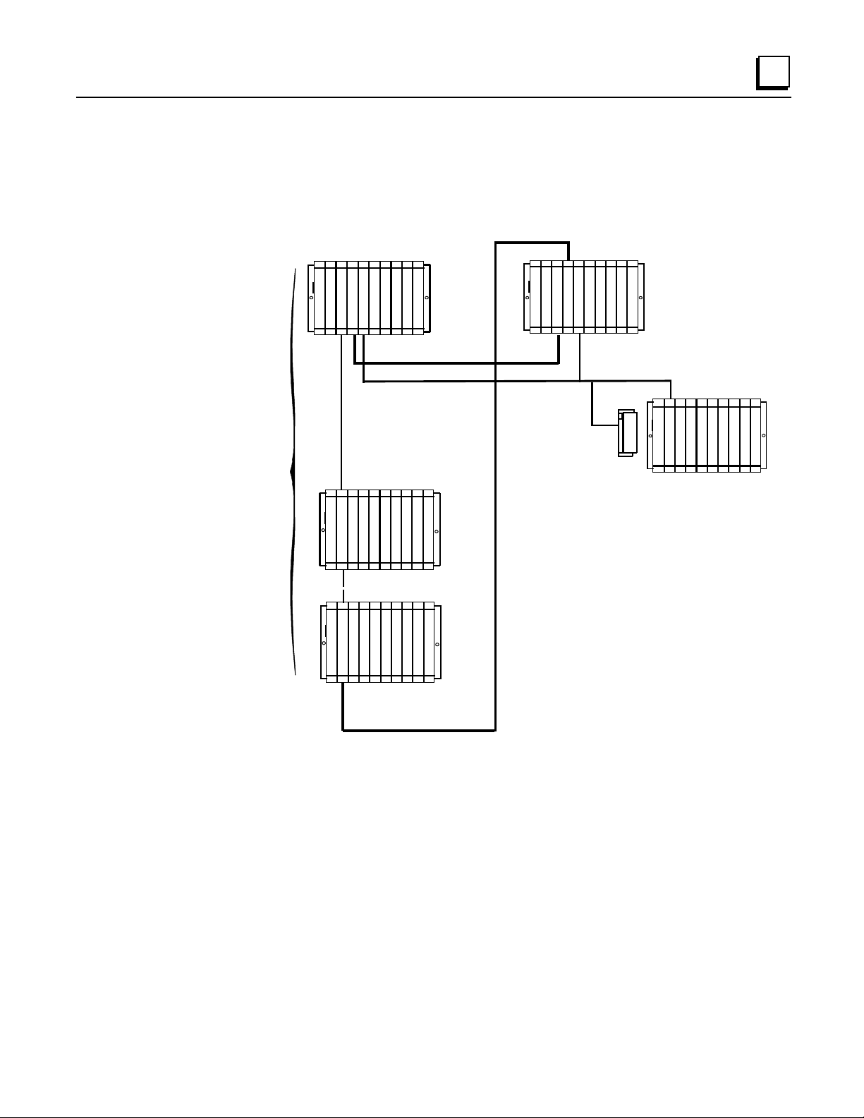
Enhanced Hot Standby CPU Redundancy System with Local I/O
The following illustration is an example of an Enhanced Hot Standby CPU Redundancy system
with Local I/O in standard Series 90-70 expansion racks.
1
LOCAL I/0
CAN BE IN
RACKS
0 - 6
Secondary Unit
RACK 0
C
P
B
R
S
T
P
C
M
U
M
RACK 1
IOIOI
B
P
R
S
M
---
---
RACK 6
IOIOIOIOI
P
B
S
R
M
G
IOIOIOI
B
C
30
OIO
TERMINATED I/O CABLE
*
I
I
I
I
O
OIO
O
O
I
IOI
O
O
O
O
P
S
B
C
P
T
U
M
Primary Unit
RACK 0
I
R
G
IOIOIOI
C
B
O
M
C
31
O
REMOTE DROP
I
I
S
P
B
L
O
C
K
OIO
C
S
A
N
N
E
R
IOIOIOI
I
O
O
O
I/O CABLE WITH BUILT-IN TERMINATION
*
IC697CBL803 (3 FEET (0.9m))
TERMINATED I/O CABLE
*
IC697CBL811 (10 FEET (3m))
IC697CBL826 (25 FEET (7.5m))
Note
Rack 7 is not available for I/O modules in an Enhanced Hot Standby CPU
Redundancy system.
GFK-1527A Chapter 1 Introduction 1-7
Page 16

1
Control St rategies
There are two different Control Strategies for Enhanced Hot Standby CPU Redundancy: GHS and
GDB.
GHS Control Strategy
The GHS control strategy has the following features:
Multiple single bus Genius I/O networks with redundant controller in each synchronized PLC
Multiple local single bus Genius I/O networks
Redundant Genius I/O driven exclusively by the active unit
Primary Unit is always the Active Unit in synchronized system unless explicitly overridden by
user or application; switchover from secondary active to primary active may not be bumpless
in certain failure conditions
Only critical control data must be transferred from Active to Backup CPU
Compatible with the release 4 based Hot Standby Redundancy Product (CPU780)
GDB Cont rol Strategy
The GDB control strategy has the following features:
Multiple dual bus Genius I/O Networks with redundant controllers in each synchronized PLC
Multiple single bus Genius I/O networks with redundant controller in each synchronized PLC
Multiple local Genius I/O networks with single or dual buses or controllers
Active unit does not automatically switch to Primary on resynchronization
Bumpless switchover with either PLC active
Critical control data plus all redundant outputs must be transferred from Active to Backup
CPU
1-8 Series 90™-70 Enhanced Hot Standby CPU Redundancy User's Guide – May 2000 GFK-1527A
Page 17

Basic Enhanced Hot Standby Operation
In an Enhanced Hot Standby CPU Redundant system, Genius I/O Blocks are normally configured
for Hot Standby operation. Genius I/O Blocks can also be configured for the less frequently used
Duplex operation, but only with the GDB Control Strategy. When configured for Hot Standby
operation, the blocks must choose between outputs from the Genius Bus Controller at serial bus
address 31 and the Genius Bus Controller at serial bus address 30. If outputs from both Genius Bus
Controllers are available, then the blocks will prefer the outputs from bus address 31. If there are
no outputs from bus address 31 for three consecutive Genius I/O bus scans, the blocks will use the
outputs from bus address 30. If out puts are not available from ei t her bus address 3 1 or 30, t he
outputs go to their configured default (OFF or hold last state).
For Hot Standby CPU Redundant systems, the Genius Bus Controllers in the Primary Unit are
normally configured at serial bus address 31 and the Genius Bus Controllers in the Secondary Unit
are normally configured at serial bus address 30.
It is possible to configure Genius I/O networks in which there is not a redundant bus controller in
the synchronized PLC. It i s not necessar y for th e serial bus addresses to be 31 in the Prim ary unit
and 30 in the secondary for such networks.
1
In an Enhanced Hot Standby CPU Redundancy system, only the active unit may control the
redundant Genius outputs. This is accomplished differently in the two control strategies:
Output Control with GHS
In the GHS control strategy, the PLC CPU allows only the active unit to control the outputs. When
the Primary Unit is active (GBCs at bus address 31), the PLC CPU allows both units to send
outputs to the blocks. The result is a bumpless switchover if the Primary Unit fails while it is the
active unit.
If the Secondary Unit is active, the PLC CPU automatically disables outputs from the redundant
GBCs in the Primary Unit. That means the Genius I/O blocks will only receive out p u ts from th e
Secondary Unit (bus controllers at serial bus address 30).
Output Control with GDB
In the GDB control strategy, both the Primary and Secondary Units send outputs regardless of
which one is active. The user is resp onsible for ensurin g tha t all redundant outpu ts are tran s ferred
from the active unit to the backup unit. Because the same output values will then be present in both
units, the blocks will receive the same outputs (regar dl es s of wheth er the Primary or the Secondary
Unit is active). There is no output glitch (data interruption) on switchover since both units are
always sending outputs.
GFK-1527A Chapter 1 Introduction 1-9
Page 18
1
B
R
B
Basic CPU Redundancy Setups
Ther e are three basi c C P U Redundan cy setu p s :
Singl e Bus with Preferred Master
Single Bus with Floating Master
Dual Bus with Floating Master
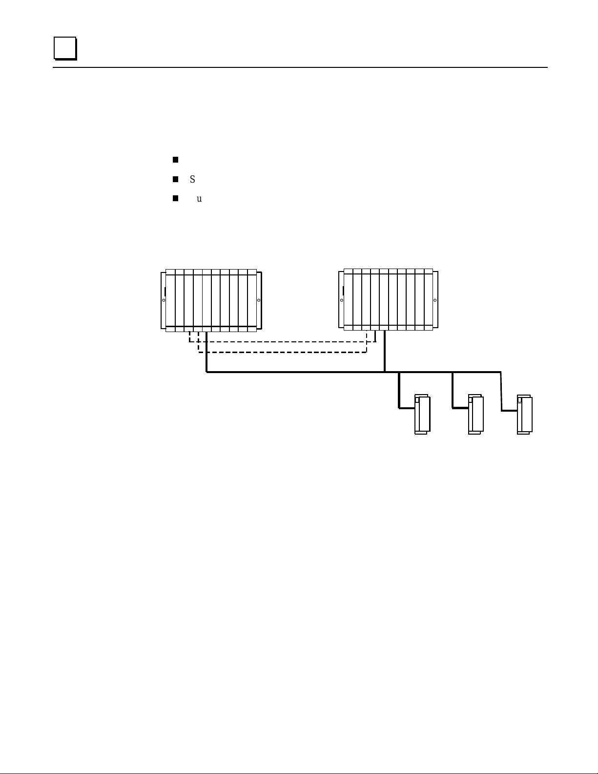
Single Bus with Preferred Master: GHS Control Strategy
This type of system uses a single Genius bus with bus controllers in each PLC. The Primary Unit
is always chosen as the active unit when the units initially synchronize.
Secondary Uni t Prima r y Uni t
C
P
B
R
G
P
S
T
C
B
U
M
M
C
30
C
B
R
P
S
G
P
T
C
B
U
M
M
C
31
Only Critical Data Transferred
PS.............. Power Supply..
CPU........... Central Processor Unit.
TM............ Bus Transmitter Module
CM........... Redundancy Communications Module
GBC............ Genius Bus Controller
LOCK....... Genius I/O Block (or Field Control)
B
L
O
C
K
B
L
O
C
K
B
L
O
C
K
The single bus with preferred master setup is suitable if:
A. The application does not require redundant I/O buses, AND
B. It is desirable to minimize the amount of data transferred between units, OR It is desirable
that the Primary Unit always becomes active at synchronization.
Single Bus with Preferr ed Ma ster requ ires selection of the GHS control strategy.
The GBCs must be config u red with the followin g s ettings. Note that the GBC s can also be
configured with Redundant Mode = NONE but RED CTRL provides more diagnostic s a nd will be
preferred in most installations.
Redundant Mode = RED CTRL
Paired GBC = External
Serial Bu s Addr = 31 (Primary Unit) or 30 (Secondar y Uni t)
Assuming that Redundant Mode is set to RED CTRL, the redundant I/O blocks mu st be
configured with the following settings:
(Hand-Held Monitor) CPU Redundancy = HOT STBY MODE
(Hand-Held Monitor) BSM Present = NO
(Programmin g Tool) Redundancy = YE S
1-10 Series 90™-70 Enhanced Hot Standby CPU Redundancy User's Guide – May 2000 GFK-1527A
Page 19

Single Bus with Floating Master: GDB Control Strategy
p
P
B
R
B
This type of system also uses a single bus with bus controllers in each PLC. However, no
switchover occurs on initial synchronization to make the Primary Unit the active unit.
Secondary Unit Prima r y U ni t
1
C
P
B
R
G
P
S
T
C
B
U
M
M
C
30
C
B
R
P
S
G
P
T
C
B
U
M
M
C
31
Critical Data + Redundant
uts Transferred
Out
S.............. Power Supply..
CPU........... Central Processor Unit.
TM............ Bus Transmitter Module
CM........... Redundancy Communications
GBC............ Genius Bus Controller
B
L
O
C
K
B
L
O
C
K
B
L
O
C
K
LOCK....... Genius or Field Control I/O Block.
The single bus with floating master setup is suitable if:
A. The application does not require redundant I/O buses, AND
B. It is desirable that the active unit not switch on initial synchronization, AND/OR
The system cannot tolerate the potential for a bump in the outputs when switching from
the secon dary acti ve t o t he primary active in fa ilure condi tions.
Single Bus with Floating Mast er r equ ires selection of the GDB control strategy.
The GBCs must be config u red with the followin g s ettings. Note that the GBC s can also be
configured with Redundant Mode = NONE but RED CTRL provides more diagnostic s a nd will be
preferred in most installations.
Redundant Mode = RED CTRL
Paired GBC = External
Serial Bu s Addr = 31 (Primary Unit) or 30 (Secondar y Uni t)
Assuming that Redundant Mode is set to RED CTRL, the redundant I/O blocks mu st be
configured with the following settings:
(Hand-Held Monitor) CPU Redundancy = HOT STBY MODE*
(Hand-Held Monitor) BSM Present = NO
(Programmin g Tool) Redundancy = YE S
* Configuration as Duplex mode is also permitted; duplex default also needs to be properly
selected. (See “Duplex CPU Redundancy” on page 1-13.)
GFK-1527A Chapter 1 Introduction 1-11
Page 20

1
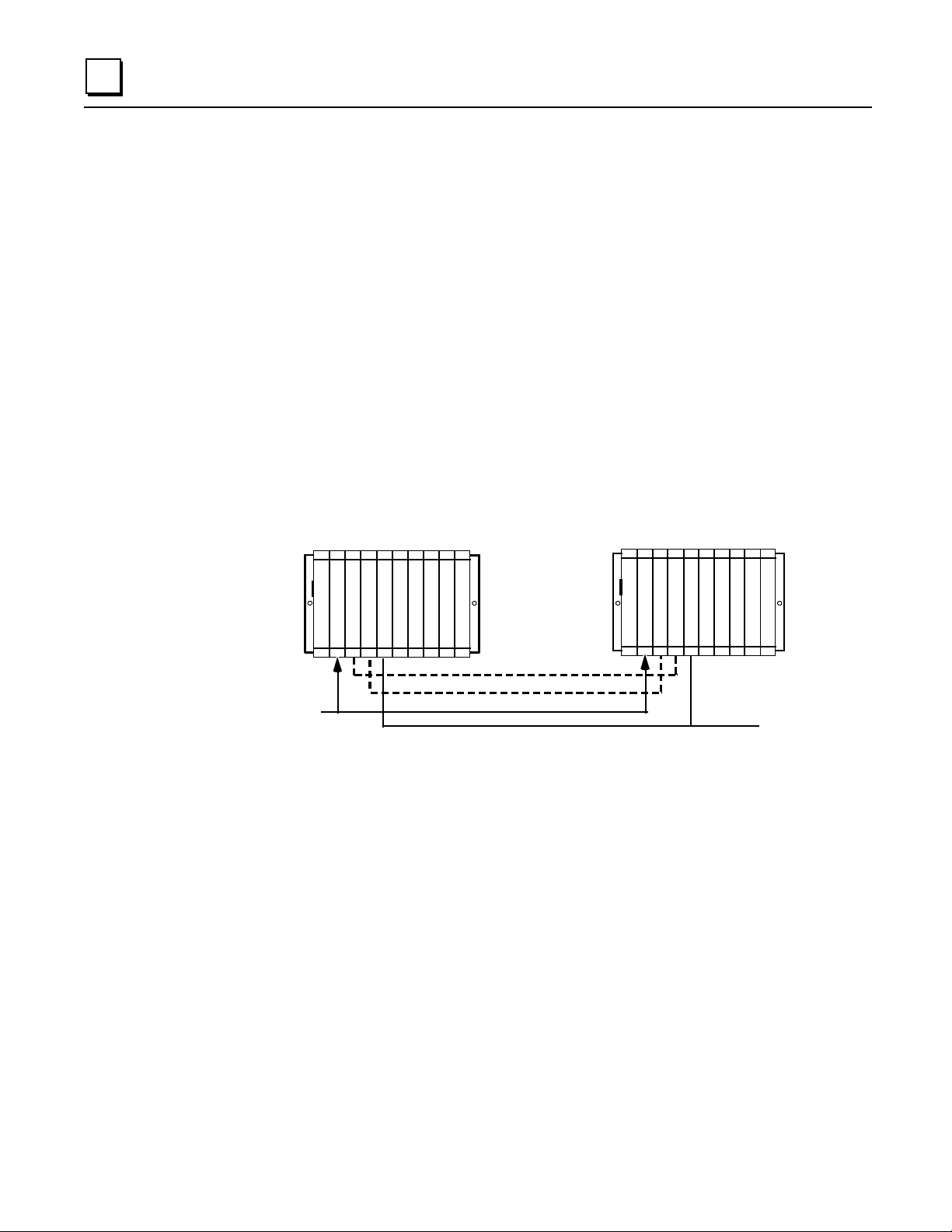
Dual Bus with Floating Master: GDB Control Strategy
This type of system uses dual buses with bus controllers in each PLC. No switchover occurs on
initial synchronization to make the Primary Unit the Active Unit. Bus Switch ing Modules (BSMs)
are required in accordance with the traditional configuration of a Dual Bus network. This option
pr ovides redundan c y of both the P L C and the I/O bus.
Secondary Unit Prima r y U ni t
C
P
B
R
G
P
S
U
G
T
C
B
B
M
M
C
C
30
30
Critical Data + Redundant
Outputs Transferred
C
B
R
P
S
G
P
U
Bus Switching Module
G
T
C
B
B
M
M
C
C
31
31
B
L
O
C
K
The Dual Bus with floating master setup is suitable if:
A. The application requires redundancy of the PLC and I/O bus, AND
B. The Active unit should not switch when the Primary Unit is returned to service.
Dual Bus with Floating Mast er r equires sel ecti on of the GDB contr ol stra t egy.
The GBCs must be confi g ured with the following settings
Redundant Mode = DB/RC (Dual Bus/Redundant Controlle r)
Paired GBC = INT/EXT (Internal External)
Serial Bu s Addr = 31 (Primary Unit) or 30 (Secondar y Uni t)
The I/ O block s must be con fi g u red with th e fol l owing settings:
(Hand-Held Monitor) CPU Redundancy = HOT STBY MODE*
(Hand-Held Monitor) BSM Present = YES
(Hand-Held Monitor) BSM Controller = YES or NO (depending on the block)
(Programmin g Tool) Redundancy = YE S
B
L
O
C
K
B
L
O
C
K
* Configuration as Duplex mode is also permitted; duplex default also needs to be properly
selected. . (See “Duplex CPU Redundancy” on page 1-13.)
1-12 Series 90™-70 Enhanced Hot Standby CPU Redundancy User's Guide – May 2000 GFK-1527A
Page 21

Duplex CPU Redundancy
Only discrete blocks (or Remote I/O Scanners with only discrete modules) can be
configured for Duplex CPU Redundancy mode. Blocks or I/O Scanners configured for
Duplex mod e receive outputs from BOTH bus controller s 30 and 31, and com p are them.
If devices 30 and 31 a gree on an outp ut state, the ou tput goes to th a t s tate. If devices 30
and 31 send different states for an output, the block or I/O Scanner defaults that output
to its pre- s elected Dup lex Defaul t State. F or ex ample:
1
Commanded State
from D evic e
Number 31
On On Don’ Care On
Off On Off Off
Off Off Don’t Care Off
On Off On On
If either device 30 or 31 stop s sending outputs to the block or I/O Sc a nner, outputs wi ll be direct ly
controlled by the remaining device.
Online Programming
On-line changes to the application program are permitted in both the active unit and the backup
unit. The programming device mu s t be connected to the system in which changes are to be made
in order to make any on-line changes. Note that all precautions regarding power source and
groun d ing for connecting the programming device mu st be followed in accordance with
instructions in the
A connect ion and di s connecti on of t he parallel programm er cable should only be ma d e wi th the
programmer proper ly grounded, and programming software proper l y booted up and in OFF-LINE
mode. For more information, refer to the
Manual
, GFK-0262.
Commanded State
from D evic e
Number 30
Series 90-70 Programmable Controller Installation Manual
Duplex Default
State in the Block
or I/O Scanner
Series 90-70 Programmable Controller Installation
Actual Output
State
, GFK-0262.
On-Line Repair
An Enhanced Hot Standby CPU Redundancy system permits online repair of failed components
with out disrupt ing the process under control. Control stat u s of both the Prim ary and the Secondary
units can be monitored by the LEDs on the Redundancy Communications Module in each system.
When a component of the active unit fails, control switches to the backup unit. The failed
component can then be replaced after first removing power from the rack in which it is installed.
After r eplacement of the failed compon en t and return ing power to the rack, th e ba ck u p unit
resynchronizes with the currently active unit. The unit that had failed, which was previously the
active unit, determines its role in the system based on configured control strategy.
Online repair is described in more detail in chapter 5.
GFK-1527A Chapter 1 Introduction 1-13
Page 22

Chapter
2
2
System Components
This chapter describes the hardware components for an Enhanced Hot Standby CPU Redundancy
system.
System Rack s
Redundancy CPU
Redundancy Communications Module
Bus Transmitter Module
Bus Receiver Module
Genius Bus Controller
For Installation Instructions
For detailed installation instructions for the Series 90-70 PLC, refer to GFK-0262, the Series 90-70
Programmable Controller Ins tal lation Manual.
System Racks
The following Series 90-70 I/O racks may be used in a Hot Standby CPU Redundancy System:
Use of Series 90-70 VME Integrator racks (IC697CHS782 and IC697CHS783) in a Hot Standby
CPU Redundancy System is not supported.
IC697CHS750, 5-slot rear mount - standard rack
IC697CHS790, 9-slot rear mount - standard rack
IC697CHS791, 9-slot front mount - standard rack
IC697CHS770, redunda nt rack - rear mount
IC697CHS771, redundant rack - fro nt mount
GFK-1527A 2-1
Page 23
2
y C
Redundanc y CPU
The redundancy CPUs have been designed specifically for Series 90-70 Hot Standby CPU
Redundancy applications.
Features
The Enhanced Hot Standby CPU supports floating point calculations, offers remote programmer
keyswitch memory protection, and has seven status LEDs. Operation of the CPU may be
controlled by the three-position RUN/STOP switch on the module, or remotely by an attached
programmer. Program and configuration data can be locked through software passwords or
manually by the memory protect keyswitch. When the key is in the protected position, a
progr ammer connected to th e Bus Tr ansmitt er M odu le can only change progr am and config uration
data.
In a Hot Standby CPU Redundancy system, one CPU is configured as the Primary CPU and the
other as the Secondary CPU. The Primary unit an d the Secondary unit must each have a
Redundancy CPU installed in slot 1 of rack 0.
Secondary Unit Primary Unit
P
S
CGR935
or
CGR772
in these slots
C
B
R
P
U
G
T
C
B
M
M
C
30
Redundancy Communications Link
Redundanc
ommunications Link
C
B
R
T
M
G
C
B
M
C
31
Genius Bus
P
P
S
U
Not all features of other Series 90-70 CPUs are available in redundancy models. See chapter 4 for
details.
2-2 Series 90™-70 Enhanced Hot Standby CPU Redundancy User's Guide – May 2000 GFK-1527A
Page 24

CPU Architecture
The CGR772 and CGR935 have an 80486DX4 microprocessor, on-board memory, and a dedicated
VLSI proce s sor for per f orming Boolean opera tions. The CG R772 and CGR935 interface to serial
ports and the system bus. The microprocessor provides all fundamental sweep and operation
control, plu s e xecut ion of non- Boolean func tions. Bool ean functi ons ar e ha ndled by the dedi c ated
VLSI, Boolean Coprocessor (BCP).
2
Model
CGR772 96 80486DX4 2048 2048 512K Bytes Yes
CGR935 96 80486DX4 12288 12288 1 Megabyte Yes
Speed
(MHz)
Processor
Input
Points
Output
Points
Expansion
Memory
Floating
Point Math
Expansion Memory Board
Program and data memory are provided by an attached expansion memory board with 512K Bytes
of user memory for CGR772 and 1 Megabyte of user memory for CGR935. The expansion
mem ory board pr ovides RA M memory for program and data stor age. Error check ing is provid e d by
a CPU ch eck sum routine. Logic progr am memory is continual ly error- ch eck ed by the CPU a s a
background task. Memory pari ty errors ar e reported to the microprocessor when they occur.
The RAM memory on the expansion memory board is backed-up by the Lithium battery mounted
on the CPU module.
Watchdog Timer
The CPU provides a watchdog timer to catch certain failure conditions. The value of this timer can
be set from 10 milliseconds to 1000 milliseconds. The default is 200 milliseconds. The watchdog
timer resets at the beginning of each sweep. The watchdog timer should be set to allow for the
expected scan
two fail wait times.
plus
GFK-1527A Chapter 2 System Components 2-3
Page 25
2
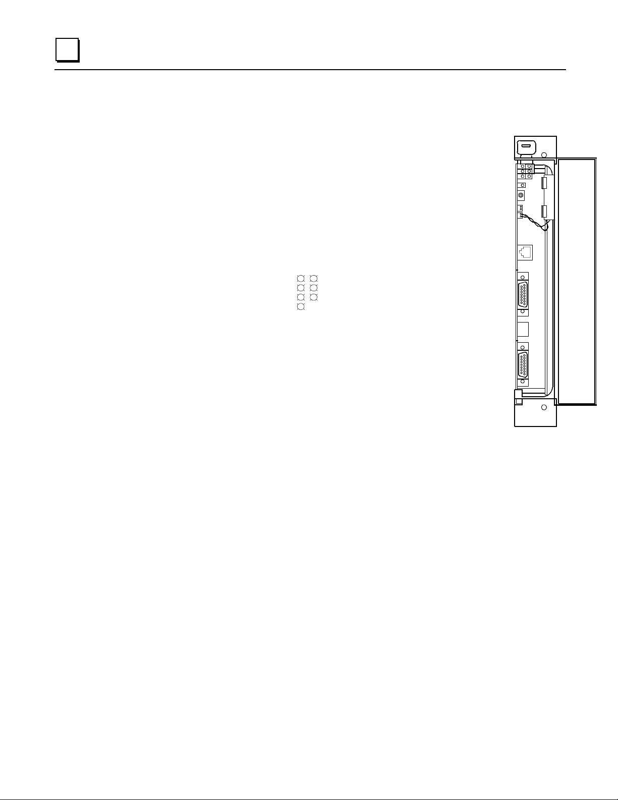
CPU Features
Memory Pro tect Keyswitch
The Memory Protect keyswitch can be used to manually
lock program and configuration data from access by a
remote programmer (serial or Ethernet). When the key is
in the ON p os ition , program and con figurati on data
only be changed
by a programmer connected to the Bu s
Tran sm itter Module.
CPU LEDs
OK:
The OK LED is ON when the CPU is functioning properly. The
OK
RUN
EN
P1
P2
P3
MEM PROTECT
OK LED blinks when the CPU executes power-up diagnostics, when
the remote unit is powered-up, or if the system has failed. If the system
has failed and the OK LED is blinking, the CPU can still communicate
with the programm er (the CPU cannot commun i cate with the
programmer during power-up diagnostics). If the OK LED is OFF, the
system has failed and the CPU cannot communicate with the
programmer.
can
Memory
Protect
Keyswitch
LEDs
CPU Mode
Switch
Battery
Connectors
Port 1
RS-232
Port 2
RS-485
Port 3
RS-422/485
B
A
T
T
E
R
Y
RUN:
This LED is ON when the CPU is in the RUN/ENABLE or RUN/DISABLE mode. It is
OFF when the CPU is in STOP mode.
ENabled
MEMory PROTECT:
:
This LED is ON when outputs are enabled and OFF when outputs are disabled.
This LED indicates the status of the memory protect keyswitch. It is ON
when the keyswitch is in the ON position. It is OFF when the keyswitch is in the OFF position.
P1, P2, P3:
LED blinks intermittently when there is serial communications on the indicated serial
port (Port 1, Port 2, or Port 3).
Batter y Co nnector s
There are two identical battery connectors. The battery currently installed can remain connected
while a new battery is being installed, minimizing the risk of data loss. A Low Battery Warning
occurs when the battery needs replacement.
When the CPU is in storage, the battery can be disconnected if there is no application program
stored in memory. If a program is stor ed in memory, the battery sh ould not be disconnect ed , or the
data will be lost.
2-4 Series 90™-70 Enhanced Hot Standby CPU Redundancy User's Guide – May 2000 GFK-1527A
Page 26

CPU Mode Switch
2
The CPU Mode switch selects the op eratin g mode o f the CPU:
or
switch position restricts the ability of the programmer to put the CPU into certain modes, as shown
in the fo llo wing table.
. The CPU mode can also be controlled from the programmer. However, the CPU Mode
STOP
CPU Mode Switch Position Allowable Programmer
Mode Command
Run/Outputs Enabled Run/Enabled
Run/Disabled
Stop
Run/Outputs Disabled Run/Disabled
Stop
Stop Stop
RUN/ENABLED , RUN/DIS ABLED
Run/Outputs Enabled Mode
In this mode, the CPU executes all portions of the sweep normally.
Run/Outputs Disabled Mode
In this mode, the CPU executes all portions of the sweep normally, but physical outputs are held in
their default state and remain unchanged. Refer to Chapter 4 for important information about
Run/Disabled mode in a Hot Standby CPU Redundancy system.
,
Stop Mode
In Stop mod e, the CPU commu n icates with the programmer and th e d evices conn ected to th e ser ial
port , com municat es with other communications modul es such as the eth ernet modul e, and recover s
fault ed modules. Values in the I/ O ta bl es can be changed using the programm ing comput er .
The STOP/IOSCAN mode
detailed information.
is not a valid mode
in a redun dancy system. Refer to Chap ter 4 for
Port 1
The RJ-11 connector provides an RS-232 compatible serial port.
Port 2
The 15-pin D-connector is an RS-485 compatible serial port.
Port 3
The 15-pin D-connector at the bottom of the module provides an RS-422/RS-485 serial port. For
applications requiring RS-232 communications, an RS-232 to RS-422 converter (IC690ACC900)
or RS-232 to RS422 miniconverter (IC690ACC901) is available.
Note
An RS-422 Isolated Repeater/RS-232 Converter (IC655CCM590) is available for
applications requiring ground isolation where a common ground cannot be
established between components.
GFK-1527A Chapter 2 System Components 2-5
Page 27

2
Redundanc y Communications Module
The Redundancy Communications Module (RCM), catalog number IC697RCM711 or
IC687RCM711 (½ slot version), provides a communications path for sharing data between the two
CPUs in the redundant system. In a synchronized system, I/O data is controlled by one unit (the
active unit) but is shared between both units (active and backup units).
An RCM must be in both the Primary PLC and the Secondary PLC. The RCM must reside in
rack 0. Th er e can be no empty slot between the RCM and th e C P U (there can be other modules).
Primary Unit Secondary Unit
( RACK 0 )
R
C B
P
B
G
C
S
T
B
P
M
M
C
U
31
Redundancy Communications Link
Redundancy Communications Link
If the other PLC has only one rack, the Redundancy Communications Module connects directly to
the Bus Transmitter Module. If the other PLC has expansion racks, the RCM connects to a Bus
Receiver Module in the last rack. The termination plug at the end of the bus is not required since
the I/O cables for redundancy systems have termination built-in to the cables.
Primary Unit Secondary Unit
( RACK 0 )
( RACK 0 )
C
R
P
U
C
T
M
M
( RACK 0 )
G
B
C
30
P
S
C
R
C B
P
B
G
C
S
T
B
P
M
M
C
U
31
Redundancy Communicatio ns Link
PSB
R
M
Redundancy Communicatio ns Link
P
S
PSB
R
G
C
B
P
T
U
M
C
M
30
R
M
Unit Select Pushbutton
The Redundancy Communications Module's pushbutton can be used to manually switch control
from the
1 second and released. Switching between units can also be controlled from the application
program with a SVC_REQ function.
The pushbutton status is checked by the PLC CPU software. After a switch has been requested,
you must wait 10 seconds before requesting another switch.
acti v e
unit to the
unit if the backup unit is
backup
READY. T
he switch must be pressed for
2-6 Series 90™-70 Enhanced Hot Standby CPU Redundancy User's Guide – May 2000 GFK-1527A
Page 28

2
Connector
LEDs
BOARD OK
The top connector on the Redundancy Communications Module
must be connected vi a an I/O cable t o the last rack of t he
other
PLC. If n o expansion rack is used, it is connected t o the lower
conn ector on the Bus Tr ansmitt er M odu le of the other system. The
LOCAL SYSTEM READY
LOCAL SYSTEM ACTIVE
REMOTE SYSTEM RE ADY
REMOTE SYSTEM ACT IVE
Unit Select
Pushbutton
I/O cable with built-in termination is available in three lengths:
IC697CBL803, 3 feet (0.9 meters)
IC697CBL811, 10 feet (3 meters)
IC697CBL826, 25 feet (7.5 meters)
Connector
Communications
for
Cable
The lower con nector is not used.
RCM Status LEDS
The RCM's five status LEDs are always updated by the appropriate system.
The module automatically turns off four of the LEDs (not the board OK LED)
if they are not updated within 500ms.
These LE D s report the status of t he health of the RCM and control status of
the Hot Standby CPU Redundancy system. The status provided by these
LEDs can also be read from the application program logic in an area of %S
memory (%S33 - %S39). These status bits are read-only.
The term
Local System
system t o wh ich the RCM i s con nected via the communications cable. Each RCM h as an
associated local and remote sy s tem.
below means the system where the RCM resides.
Remote System
is the
Board OK:
This LED lights when diagnostics are complete and the RCM has been determined to
be operat i ng nor mall y. It sta ys on unless the RCM fails .
Local System Ready
:
Indicates whether the local system is ready to become the active system
in a redundant PLC configuration. If this LED is on, the local system has been configured for
redundancy, is in RUN mode, and is able to take control of the redundant system if selected as the
active system. The local system MUST set the state of this LED at least once each sweep; if it
doesn't, the hardware forces the LED off after the timer expires.
Local System Active
:
Indica tes whether the local system is the controlling (a ctive) system in a
redundancy system. The local system MUST set the state of this LED at least once during each
sweep; if the local system fails to set the state of the LED, the hardware forces the LED off after
the timer expires .
Remote System Ready
:
Indicates whether the remote system is ready to become the active
system i n a redundant PLC system. If the LED is on, th e r emote system h as been config ured for
redundancy, is in RUN mode, and is able to take control of the redundant system if selected as the
active system. The remote system MUST set the state of this LED at least once during each sweep;
if the remote system fails to set the state of the LED, the hardware forces the LED off after the
timer expires.
Remote System Acti ve
:
Indicat es whether th e r emote system is the control ling (act ive) system
in a redundancy scheme. The remote system MUST set the state of this LED at least once during
each sweep; if the remote system fails to set the state of the LED, the hardware forces the LED off
after the timer expires.
GFK-1527A Chapter 2 System Components 2-7
Page 29

2
Bus Transmitter Module
A Bus Transmitter Module (BTM), catalog number IC697BEM713 or IC687BEM713 (½ slot
version), must be in r ack 0 of both th e Primary PLC and the Secondary PLC in a Hot St andby CPU
Redundancy system. The Bus Transmitter Module provides a path for Redundancy
communications when connected to the Redundancy Communications Module as described
previously. Each PLC in the redundancy system (Primary and Secondary) must have a BTM and
an RCM in ra ck 0.
P
S
B
C
P
T
M
U
Primary Unit
( RACK 0 )
R
G
C
B
M
C
Secondary Unit
( RACK 0 )
B
P
C
T
S
P
M
U
R
G
C
B
M
C
31
Redundancy Communications Link
Redundancy Communications Link
30
When included as a bus communications module in an I/O expansion system, the BTM is a high
speed parallel interface wh ich propa ga tes the I/O bus s i gn als through a cable to a Bus Recei ver
Module located in the first I/O expansion rack. The BTM also provides a high speed parallel
connection to the programmer.
Connectors
The lower con nector on the BTM is used to connect t o a
Redundancy Communicatio ns Module i n the othe r
Redund ancy system or to a Bus Recei ver Module in the first
expansion rack. Standard parallel I/O cables are used to
PROG RA MMER P ORT EN A BL E D
EXPANSION PORT ENABLED
LEDs
MODULE OK
make th e con nection to a Bus Receiver M odule. Cabl es with
built-in termination are used to make the connection to a
Redundancy Communications Module.
The upper connector provides a parallel connection to a Work
Station Interface (WSI) board installed in the programmer for
the Series 90-70 PLC.
Connector for
Programmer
(Programm e r Port)
Bus Transmitter Module Status LEDs
Module OK:
completed its power-up configuration of the BTM, and has
polled (or attempted to poll) each expansion rack in the
system. It is OFF when any of these condit ions are not met.
Programmer Port Enabled
or ON when th e pr ogrammer an d the PLC are
communicating. It is
Expansion Port Enabled:
The top LED is ON when the CPU software has
:
The middle LED is either
when th ey are not comm un icating .
OFF
blinking
The bot tom LED shows the stat u s of
Connector for
Redundancy
Communications
or Bus Re ce iver
Module
(Expansion Port)
the exp ansion bus . This LED is ei ther blinking or ON wh en
the BTM is communi cating.
2-8 Series 90™-70 Enhanced Hot Standby CPU Redundancy User's Guide – May 2000 GFK-1527A
Page 30

Bus Receiver Module
The Bus Receiver Module (BRM), catalog number IC697BEM711, is the expansion rack interface
to the I /O bus. The Bus Receiv er Modul e connects t o a Bus Transmitter Modul e in ra ck 0 or to a
Bus Recei ver Module in the previ ou s rack via a par allel I/ O bus ca bl e.
In a CPU Redundancy system with expansion racks, the last bus connection is to a Redundancy
Communicati ons Mod u le, as explained previ ou s ly.
Connectors
2
The top connector on the Bus Receiver M od u le is for connection
to the previous Bus Transmitter or Bus Receiver Module.
The lower con nector on the Bus Receiver Module is for
connection to the upper connector of a Bus Receiver Module in
the next expansion rack or to the upper connector of a
Redundancy Communications Module.
Cables and Termin ation
In an expansion I/O system, th e cable between Bu s
Tran sm itter/Receiver m odu les is an 18 twi sted-pair cable with a
ground shield. The total maximum cable length from the CPU
rack to the most distant expansion rack (at the same ground
poten tial) is 50 feet. Standard parallel I/O bus cabl es th at meet
this specification are available
in lengths of 5, 10, 25, and 50 feet.
In a non-redundant PLC system, thi s bus must be
terminated using terminator plug (IC697ACC702) on the
bottom con nector of the last Bus Receiver. All BRMs are
shi pped from the factory with a terminator plug installed.
For a red undant PLC system, thes e terminat or plugs must
be removed from all BRMs.
LEDs
BOARD OK
LAST RACK
BUS ACTIVE
Connector to
Previous BTM
or BRM
Connector to
Redundancy
Communications
Module or Bus
Receiver Module
In a Hot Standby CPU Redundancy system a special I/O cable with
built-in termination is used. Do not use the resistor plug with the
terminat ed cable.
Bus Receiver Module Status LEDs
:
Board OK
the expansion rack and at least one module in that rack respo nds to the CPU reque sts for
info rma tion. It is
Last Rack
conn ector of thi s Bus Rec eiver Module and is
Expansion Bus Active
the last 500 ms. Otherwise it is off and I/O modules in the rack are held in their default state.
GFK-1527A Chapter 2 System Components 2-9
The top LED is ON when the CPU completes its power-up configuration of
when an y of th es e conditions are not met.
OFF
:
The middle LED is ON when the terminator plug is installed in the bottom
when it is not installed.
Off
:
The bottom LED ON indicates activity on the expansion bus in
Page 31

2
)
Genius Bus Controller
The Genius Bus Controller (IC697BEM731) interfaces the Series 90-70 PLC to a Genius I/O bus.
The bus controll er s cans bus devices asynchronousl y an d ex ch anges I/O dat a wi th the CPU once
per scan .
Location of GBCs and Blocks
For dual bus Genius networks, the Genius bus controllers should be placed at the same end of the
bus, as pi ctured belo w. In p ar ticular , the Secondary Unit must be placed at one en d of the bus an d
the Primary Unit m u st be placed between the Secon d ary Unit and th e G en ius I/O blocks. N o I/O
blocks or other devices should be locat e d on the bus between the bus con t rollers. Placing th e bus
controllers and blocks in this manner minimizes the risk of a bus break between the two CPUs. A
bus break between the CPUs could result in only some blocks switching busses, and make the other
blocks inaccessible to one of the CPUs. It also allows the Primary Unit to continue to control the
I/O in bus failure conditions that might otherwise result in loss of inputs and unsynchronized
control of outputs.
Since the recommended configuration still has the possibility of a bus breaking between the two
CPUs, you may want to program the application to monitor the status of the buses from the unit
configured at the end of the buses and request a role switch or bus switch if the bus is determined to
be broken. Locating singl e bu s n etworks in th e same manner h as similar advantages.
Secondary Unit Primary Unit
C
P
B
R
G
P
S
U
PS........ Power Supply..
CPU...... Central Processor Unit.
BTM..... Bus Transmitter Module
RCM...... Redundancy Communications Module
GBC.... . Genius Bus Controller
BLOCK.. Genius I/O Block (or Field Control
G
T
C
B
B
M
M
C
C
30
30
C
B
R
P
S
Bus Switching Module
G
P
U
G
T
C
B
B
M
M
C
C
31
31
B
L
O
C
K
B
L
O
C
K
B
L
O
C
K
For fastest switching, all Genius Bus Controllers in the Hot Standby CPU Redundancy system
shoul d be in the main rack, or in a rack driven by the main rack's power supply. Th is will cau s e th e
Genius Bus Controller to lose power at the same time that the CPU loses power and allow the
backup unit to gain full control of the I/O as soon as possible. Each GBC has an output timer,
which it resets during every output scan. If the GBC determines that the CPU in its PLC has failed,
it will stop sending outputs to its Genius I/O block. This allows the other GBC to take control of
the I/O.
2-10 Series 90™-70 Enhanced Hot Standby CPU Redundancy User's Guide – May 2000 GFK-1527A
Page 32

Single Bus Genius Networks
When using single-bus Genius networks in a Hot Standby CPU Redundancy system, one Genius
Bus Controller for the bus mu st be l ocated in the Primary PLC and one in the S econdary PLC.
There can be multiple Geni u s busses in the system.
The bus controll er s in th e Primar y PLC are assigned Serial Bus Ad dress 31. Th e bus controllers in
the Secondary PLC are assign ed Ser ial Bus Addr ess 30. Data from Seria l Bus Address 31 in the
Prim ary PLC is the "preferred" data. If the GHS Control Str ategy is used, the Primary PLC is
normally the active unit in the redundancy system.
Each bus can have up to 30 Genius devices connected to it. One Serial Bus Address m ust be
reserved for a Han d -held Monitor. Any type of Genius device ca n be connect ed to the bus. A
Genius I/O device will use outputs from Serial Bus Address 31 in preference to data from Serial
Bus Address 30.
When u sing the GHS Con trol Strat eg y, the blocks r eceive outpu ts from th e bu s controllers in the
active unit. With the GHS Control Strategy, it is not necessary to transfer outputs from the active
unit to the backup unit.
Secondary Unit Primary Unit
2
C
P
S
G
B
P
T
U
M
G
R
G
B
B
C
B
C
C
M
C
30
30
30
Genius Bus
Genius Bus
C
B
R
P
S
G
G
G
B
P
T
U
M
B
C
B
C
C
M
C
31
31
31
Genius Devices
Genius Devices
Genius Bus
PS........ Power Supply
CPU...... Central Processor Unit.
RCM..... Redundancy Communications Module
BTM..... Bus Transmitter Module
GBC...... Genius Bus Controller
BLOCK.. Genius I/O Block (or Field Control)
When u sing the GDB control strat egy, all redundant Genius outp ut s mu st be t ransferred from the
active to the backup unit. Therefore, outputs are determined by the active unit regardless of which
bus c ontroller provi des the outputs to the blocks.
As a safety feature, a watchdog timer protects each Genius I/O link. The Genius Bus Controller
periodically resets this timer. If this timer expires, the bus controller stops functioning and the
Channel OK LED turns off. If this happens in a CPU Redundancy system, the other bus controller
provides data to the Genius I/O blocks. The cause of the failure must be fixed to re-establish
communications.
Dual Bus Genius Netw orks
When using dual bus Genius networks in a Hot Standby CPU Redundancy system, two Bus
Controllers for the bus pair must be located in the Primary PLC and two more in the Secondary
PLC. There can be multiple dual bus pairs. The bus controllers in the Primary PLC are assigned
Serial Bus Address 31. Th e bus controll ers in the Secondary PLC are assigned Serial Bus Address
GFK-1527A Chapter 2 System Components 2-11
Page 33

2
30. Data from Serial Bus Address 31 in the Primary PLC is the "preferred" data. The GDB control
strategy must be used and all redundant Genius outputs must be transferred from the active to the
backup unit.
Each du al bu s can h ave up to 30 addi tional Geni u s d evi ces connected to it. One Serial Bus Ad dress
must be reserved for a Hand-Held Monitor. Any type of Genius device can be connected to this
bus. A Genius I/O device will use outputs from Serial bus Address 31 in preference to data from
Serial bus Addr ess 30. Outputs are determined by the Active Unit regardless of which bus
controller provides the outputs since all redundant Genius outputs must be transferred from the
active to the backup unit.
As a safety feature, a watchdog timer protects each Genius I/O link.
The bus controller periodically resets this timer. If the timer ever
expires, th e bus controll er st ops functioning and its Channel OK LED
turns off. If this happens in a Dual Bus Genius network of a CPU
Redundant system, the paired GBC in the remote CPU drives the
Genius I/O blocks. If the remote unit GBC is not available, the BSMs
swit c h buss e s an d use outputs from the oth er bus. The cause of the
failure must be reme d ied to re- establis h communicatio ns.
Connectors
LEDs
MODULE OK
CHANNEL 1 OK
NOT USED
Hand-held
Monitor
Connector
The Bus Controller has a nine-pin connector for a Hand-Held
Monitor. Bus conn ect ions are mad e to a removable t erminal boa r d .
Bus Controller LEDs
Bus
The GBC h a s three LEDs; the bottom one is not used.
Module OK:
The top LED is ON when t he board has
successfully completed the power-up diagnostics. If the powerup diagnostics detect a failure or if the board fails during
operation, the LED goes
. The LED
OFF
blinks
during the
power-up diagnostics.
CH 1 OK
successfully completed the power-up diagnostics and
The CH 1 OK LED is ON after the board has
:
if a failure has been detected
OFF
during the power-up diagnostics or if its bus or bus controller fails while the CPU is running
(even in the STOP mode). If the bus controller fails the LED remains off. For a bus failure,
such as a broken wire or excessive bus e rr ors, the LED r emains off until the failure
condition is co r re cted.
The LED also remains
until its serial bus address is configured.
OFF
Terminals
2-12 Series 90™-70 Enhanced Hot Standby CPU Redundancy User's Guide – May 2000 GFK-1527A
Page 34

Chapter
Configuration Requirements
3
This chapter defines the special configuration requirements of an Enhanced Hot Standby CPU
Redundancy system.
Programmer Connection for Configuration
In a Hot Standby CPU Redundancy system, one CPU is configured as the Primary CPU and the
other as the Secondary CPU. The Primary Unit and the Secondary Unit mu st be configured
separately. The programming device mus t be connected directl y to either th e Primary or th e
Secondary Unit to configure that unit. For a new system, STORE configuration first, then logic.
Secondary Unit Primary Unit
C
P
B
R
G
P
S
T
C
B
U
M
M
C
30
To Programmer
One Applic ation Program in Both PLCs
Although it is not necessary to use the same application program logic for both PLCs, it is difficult
to main tain a system that uses t wo di ff erent programs. If th e programs ar e not the same, l og ic
changes made in one system must be hand-keyed into the program folder for the other PLC. Other
than visual inspection, there is no way to tell if changes made in one system have been
appr opr iately made in the other.
Program Folders in Control Programming Software
With the Control programming software, a single folder may be used if the logic is identical for
both CPUs.
C
B
R
P
S
G
P
T
C
B
U
M
M
C
31
Genius Bus
GFK-1527A 3-1
Page 35

3
Program Folders in Logicmaster 90
With th e Log icmast er pr ogramming s oftwa re, there must be diff erent fold ers for each
configu ration . I f the logic is id en tical for both PLCs, a third folder could be used for the logi c an d
refer ence tables. This res u lts in three fold ers for the system.
Folder A - configur ation for the Primary unit.
Fold er B - config uration for the Second ary unit.
Folder C - logic and reference tables for both systems.
CPU Configuration Parameters
When configuring a system for Hot Standby CPU Redundancy, the following additional parameters
must be set up.
Parameter Default Choices Description / Comment
I/O Scan Stop Must be set to NO
Watchdog
Timer
Redund
Type
Background
Timer
Fail-wait
Control
Strategy
Shared I/O
References
200ms 10ms to
1000ms
Primary
5ms in limit e d
window mode
Primary,
Secondary
0ms to
255ms
60ms 60ms to
400ms
GHS (CPU780)
GDB (CGR772,
CGR935)
The references within the control of the Redundancy system. See the following
paragraphs for more information. The Shared I/O selections must match exactly
between Primary and Secondary PLCs.
GHS or
GDB
The value selected should allow for the expected
plus
scan
Whether the CPU being configured is the Primary or
Secondary CPU in the Redundancy system. One
configuration must be set to Primary; the other to
Secondary.
The background window runs several diagnostic tests
that can be di sa bl e d b y setting the timer to 0ms.
These tests are run i n Constant Window and
Constant Sweep mode only if the window/sweep
time is large enough.
The time one PLC will wait on one Redundancy
Communications Module link for the other PLC to
respond before faulting that link. The CPU will try
both links before continuing its scan. Once the RCM
links are mar ked as failed, one unit or the other must
be power cycled to recover them.
Storing configuration to either unit could also
recover the RCM links.
Genius Hot Standby (GHS) or
Genius Dual Bus (GDB).
two fail wai t times .
Fault
Category
(configurable
when not
synch ronized
only)
3-2 Series 90™-70 Enhanced Hot Standby CPU Redundancy User's Guide – May 2000 GFK-1527A
Fatal,
Diagnostic
Fault actions when the CPUs are not synchronized
can be configured to select a safe shutdown or fault
tolerant operation in case a failure occurs with no
backup ready.
Page 36

Configuring Shared I/O References
Shared I/O data is transferred from the active CPU to the backup CPU each sweep. Reference
addr ess es and ranges must be config ured for th e da ta to be trans ferred. Th ere can be up to 20
Kbytes of input data (%I, %AI) and up to 28 Kbytes of output data (%Q, %AQ, %M, %R)
transferred.
Input references should be transferred to the backup unit if the program logic requires identical
inputs for the two units. Scanning the same Genius I/O blocks in both units is not sufficient to
guarantee that the inputs will be identical every sweep.
When using the GDB Control Strategy, it is necessary to transfer all Genius outputs for redundant
blocks. Otherwise, the Genius blocks would drive their outputs from the backup when the Primary
PLC was serving as the backup.
Parameter Default Range Description
%I Ref Adr %I00001 00001 to 12288* Starting address for redundant %I data region. Must
3
be byte aligned.
%I Length 0 0 to 12288* Bit length of the redundant %I data region. Length
must be a multiple of 8.
%Q Ref Adr %Q00001 00001 to 12288* Starting address for redundant %Q data region. Must
be byte aligned.
%Q Length 0 0 to 12288* Bit length of the redundant %Q data region. Length
must be a multiple of 8.
%M Ref Adr %M00001 00001 to 12288** Starting address for redundant %M data region. Must
be byte aligned.
%M Length 0 0 to 12288** Bit length of the redundant %M data region. Length
must be a multiple of 8.
%R Ref Adr %R00001 00001 to %R
conf igured limit
%R Length 0 0...%R configured
limit
%AI Ref Adr %AI00001 00001 to %AI
conf igured limit
%AI Length 0 0 to %AI
conf igured limit
%AQ Ref Adr %AQ00001 00001 to %AQ
conf igured limit
%AQ Length 0 0 to %AQ
conf igured limit
Starting address for redundant %R data region.
Word length of the redundant %R data region.
Starting address for redundant %AI data region.
Word length of the redundant %AI data region.
Starting address for redundant %AQ data region.
Word length of the redundant %AQ data region.
Limit is 2048 for IC697CGR772; **Limit is 4096 for IC697CGR772
GFK-1527A Chapter 3 Configuration Requirements 3-3
Page 37

3
Finding the Memory Available for Application Program Storage
Shared I/O data is stored in the same memory as application program storage. To find the amount
of memory available for application program(s), subtract the overall transfer data amount from the
amount of memory (512K bytes for CGR772, 1024K bytes for CGR935) available for the
application p ro g ram.
First, calculate the amounts of input and output data transferred:
Reference Ty p e Reference Size If Point Faults are
%I Bit (%I length x 4 ) ÷ 8 (%I length x 5) ÷ 8
%AI Word (%AI length x 2) (%AI length x 3)
%Q Bit
%M Bit (%M length x 4) ÷ 8
%AQ Word (%AQ length x 2) (%AQ length x 3)
%R Word
(%Q length x 4) ÷ 8 (%Q length x 5) ÷ 8
(%R length x 2)
Then, add the input amount, the output amount, and an additional 8K bytes for synchronization
information:
total bytes of input data
total bytes of output data
+
8 Kbytes
+
for synchronization information
(%I, %AI) transferred
(%Q, %AQ, %M, %R) transferred
Last, subtract this amount from the total amount available for the application.
For exa mp le, if ther e ar e 10 Kbytes of in put data tran s ferred an d 2 0 Kb ytes o f output data
tran s fer red, th en 10 Kb ytes + 20 Kbytes + 8 Kb ytes = 38 Kbytes needed for transferred data. Thi s
is subtracted from the 1024 Kbytes of total memory on the CGR935:
1024K - 38K = 986 Kbytes available for the application program on the CGR935.
System Communi cat i o ns Window Con sid erations
Disabled
: If Point Faults are
Enabled
:
The CGR772 and CGR935 model CPUs support the use of high-speed communications modules
such as the Ethernet Interface (Type 2). Requests from devices attached to these communications
modul es are handled in the System C ommunica tions Wind ow. Since these requests can be sent in
large volumes, there is the potential for the Systems Communications Window to be processing
requests for a significant amount of time. One way to reduce the risk of timing out the Redundancy
Communications Module/Bus Transmitter Module communications link between the CPUs is to
configure the System Communications Window for
LIMITED WINDOW
mode. This sets a
maximum time for the Systems Communications Window to run. Other options are to configure
the CPU sweep mode as
CONSTANT WINDOW
or
CONSTANT SWEEP
. The CPU will then cycle
through the communications and background windows for approximately the same amount of time
in both un i ts.
3-4 Series 90™-70 Enhanced Hot Standby CPU Redundancy User's Guide – May 2000 GFK-1527A
Page 38

Configuring the Redundancy CPU for Non-redundant Operation
The Redundancy CPU can be used for both redundant and non-redundant applications. For nonredundant applications, do not configure Redundancy Communications Modules in the system. If a
Bus Transmitter Module is configured set the Remote RCM Present parameter to NO. Keep all
redundancy-related parameters in their default settings.
Geni u s I/O in the non-redundant s ystem can be confi g u red for either no redundancy or external ly
paired. (If a GBC redundancy mode other than RED CTRL or NONE is selected, it will be
necessary to select the GDB control strategy. When that is done, the programmer may display
messag es that %Q and %AQ mu s t be included in th e da ta transfer . These warnings can be i gnored
when configuring the CPU for non-redundant operation).
Rack Module Configuration Parameters
Interrupts cannot be ENABLED when the configured CPU is a Redundancy CPU. When a
redundant CPU is configured, any interrupts enabled in the configuration are set to
DISABLED.
3
For redundant applications, a Bus Transmitter Module must be configured and its Remote
RCM parameter must be set to YES. (see the previous di scussion for non-redundant
applications.)
For redundant applications, a Redundancy Communications Module must be configured in
rack 0 of each system. For a given unit, the Local RCM is the one configured in that unit; the
Remote RCM is configured via the Bus Transmitter Module's Remote RCM parameter . Remote
RCMs appear as being in slot 1 of rack 7. (see the previous discussion for non-redundant
applications.)
Bus Control ler Configuration Parameters
When configuring the PRIMARY PLC, all Genius Bus Controllers configured for redundancy
must have Serial Bus Address 31.
When configuring the SECONDARY PLC, all Geni us Bus Controllers configured for
redundancy must have Seri al Bus Address 30.
Non-redundant busses with a bus controller in only one of the PLCs do not need to use Serial
Bus Address 31 or 30.
For single Geniu s bus net works, all Genius Bus Controllers i n the system mu st be configu red for
RED CTRL Redundancy with the redundant pair set to EXTERNAL, or they must be configured
fo r no redundanc y.
For Dual Bus Genius networks, all Genius Bus Controllers must be configured for Dual
Bus/Redundant Controller (DB/RC).
(It is possible to configure bus controllers in a Redundancy system with Redund Type set to
NONE, but this bypasses some impor tan t int egr ity checks, wh i ch are desirable for optimum system
operation).
GFK-1527A Chapter 3 Configuration Requirements 3-5
Page 39

3
Genius I/O Block Configuration Parameters
When using the GHS Control Strategy, if a Genius Bus Controller is set to redundant, then all
of its I/O blocks must also be set to redundant.
When using the GDB Control Strategy, if a Genius Bus Controller is set to redundant, then all of its
I/O blocks are normally configured as redundant.
If a Genius Bus Controller is set to non-redundant, all of its I/O blocks must also be set to non-
redundant.
3-6 Series 90™-70 Enhanced Hot Standby CPU Redundancy User's Guide – May 2000 GFK-1527A
Page 40

Chapter
4
Normal Operation
This chapter discusses:
Powerup of a Redundant CPU
Resynchronizati on of the Re dun dant CPU
GHS Control Strategy
GDB Control Strategy
%S References for CPU Redundancy
Scan Synchronization
Switching Control to the Backup unit
RUN Disabled Mode
Backg round User Checksum and Bac kgrou nd Window Timin g Instr ucti ons
Miscellaneous Operation Information
Genius Bus Controller Switching
Ethernet Global Data in a Redundancy CPU
GFK-1527A 4-1
Page 41

4
Powerup of a Redundant CPU
When a redundant CPU is powered up, it performs a complete hardware diagnostic check and a
complete check of the application program and configuration parameters. This causes the powerup
time of a redundant CPU to be significantly longer than the normal powerup time of a nonredundant CPU. If the Primary and Secondary systems p ower up together each C PU wil l recognize
this fact so that the Primary system will become the active and the Secondary system the backup.
Powerup consists of the following sequence of steps:
1. Powerup self-test is always performed.
2. CPU operating system is initialized and PLC memory is validated.
3. Diagnostics called during full powerup tests are performed.
4. System Configuration is verified.
5. System i s interr og ated and initialized.
6. Presence of other CPU is detect ed .
7. Redundancy Communications Modules are initialized.
8. Complete application program is verified.
9. CPU synchronizes with redundant CPU.
When th e Secondary Un it powers up , if it does not d etect the Primary Unit, the Secondary Unit
waits up to 15 seconds for the Primary Unit to power up. If the primary unit has not completed its
poweru p sequence within 15 secon d s , the Second ary Unit assu mes the Pri mary Unit is n ot pres ent.
If at this time, the Secondary Unit transitions to RUN mode, it does so as an active unit without a
backup unit.
If the Primary Unit completes its powerup sequence before the Secondary Unit, the Primary Unit
does not wait for the Secondary unit to complete its powerup sequence. If the Primary Unit is set
up to transition to RUN on powerup (that is, was powered-down in RUN mode), it transitions to a
stand-alone unit without waiting for the Secondary unit. The Secondary Unit, upon completion of
its powerup sequence, establishes communications with the Primary Unit. If transitioning to Run
mode, it synchronizes with the Primary Unit.
In either case, if one CPU fails to notify the other CPU that it is either present or powering up, the
other CPU, if transitioning to RUN, becomes the active unit and runs without a backup unit.
Resynchronization occurs after the powerup sequence is complete.
Note
If the system should be fully redundant upon powerup, the Secondary Unit must
complete power-up first but no more than 15 seconds before the Primary Unit.
The way to be sure this happens is to apply power to the Secondary Unit first.
4-2 Series 90™-70 Enhanced Hot Standby CPU Redundancy User's Guide – May 2000 GFK-1527A
Page 42

Incompatible Configurations
When two units have incompatible configurations stored (for example, both units configured for
PRIMARY or differing blocks for data transfer), then only one of the units can go to RUN mode.
If the other unit attempts to go to RUN mode or both units attempt to go to RUN mode at the same
time, a FATAL incompatible configuration fault will be logged.
If on e unit is configured for CPU Redund a ncy an d the other h as no con f igur a tion, t hen bot h uni ts
may go to RUN mode at the same time
they will not be synchronized and only the unit that has
but
been configured wi ll drive outpu ts.
Resynchronization of a Redundant CPU
When a CPU attempts to get back in synchronization with the currently active CPU,
resynchronization occurs. Resynchronization occurs any time a CPU transitions from STOP to
RUN mode. The process starts by determining which role each CPU is to play, based on
configured control strategy and PRIMARY/SECONDARY configuration as shown in the table
below.
4
Control
Strategy
GHS
GDB
Be havior during Resynchronizat ion
The Primary Unit (with Serial Bus Address 31) is always preferred. A switch occurs from the
Secondary Un it each time the Pr imary Unit resynch ronizes. Unti l th e resynchron ization is
complete, the Prima ry Uni t acts as bac k u p.
The Primary Uni t switches to active just
sweep by the Primary Unit.
The active CPU remains activ e after resynchronization withou t rega rd to whether it is in the
Primary or Secondary unit. The transitioning unit becomes the backup.
prior
to logic execution. Outputs will be driven that
If both systems are transitioning at the same time, the Primary Unit becomes the active CPU and
the Secon dary Uni t bec om es the backup.
During resynchronization, the CPUs exchange information about roles and configuration. If the
transitioning CPU detects that the role or configuration is not in agreement, that CPU is not
permitted to go to RUN mode. If both CPUs are transitioning, neither CPU is permitted to go to
RUN mode. The following items must be in agreement:
1. One CPU m u st be con figur ed a s Primary, th e other as Secondary.
2. Both CPUs must be configured for the same control strategy (GHS or GDB).
3. Both CPUs m ust have th e same Shared I/ O r ed undancy poin ts config ured.
4. If point faults are enabled on one CPU, they must also be enabled on the other if %I, %Q,
%AI, or %AQ data is transferred.
At thi s p oin t, the active unit is th e one that has been in control an d the backup un it is the one th at is
resynch ronizing. The transfer of al l configured control dat a from the active unit t o the backup
occurs unless both units are transitioning at the same time (transfer always goes from the running
unit to the resynching unit. In addition to the configured control data, the FST_SCN and
FST_EXE %S references as well as internal timer information for each common (that is, present in
both CPUs) sub-block are transferred from active to backup. Only the internal timers and
GFK-1527A Chapter 4 Normal Operation 4-3
Page 43

4
FST_E X E r eferences for program bl ocks with the same name are tr ansferr ed from the active to the
backup CPU. The result is that if one CPU is already in Run mode and the other is transitioning to
Run mode, the FST_SCN and matching FST_EXE bits are
tran s itionin g uni t. These bits ar e consider ed s ystem bi ts and set if one unit comes up alone, or if
both units come up together.
No tran s fer of data occurs at this p oint if both units are transitioning to Run mode. Instead, th e
norma l cl earing of n on -retentive data ha ppens and the FST_SCN and FS T_ EXE references are set
as in the non-redundant CPU models.
The time r i nf ormation and the FST_EX E %S refe re nce bits are no t continuously transf e r re d. The
timer information and FST_EXE references are transferred only at resynchronization time. Timer
information is calculated each sweep from the universal Start of Sweep Time transferred every
sweep.
GHS Control Strategy
In the GHS Control Strategy, the Primary Unit (with bus address 31), is always the preferred CPU.
The Secondary Unit (with bus address 30) has outputs enabled to its Genius bus controllers at all
times, whether it is in control or not. This is necessary to prevent g litching of the outpu ts when a
switch occu rs. The Primary Unit, on the other hand, must disable its out puts whenever contr ol is
manually switched to the Secondary Unit. The Primary Unit must re-enable its outputs if it is again
selected as the active unit. Gli tching of the ou tputs does not occur on a s witch from the Secondary
to the Primary Unit when it is done manually. However a glitch may occur if the switch is made
automatically due to a failure in the Secondary Unit.
For this reason, the primary CPU should normally be selected as the active unit.
Primary Unit transitions from
Secondary Unit after resynchronization. This is handled automatically by the CPU operating
system.
STOP to RUN
not
set on the first scan of the
Any time the
mode, the Primary Unit assumes control from the
The Primary Unit in the GHS Control Strategy becomes a functioning backup if control is
manually switched to the Secondary Unit. After this happens, the Secondary Unit remains the
acti ve un it and the Pr imary Unit r ema ins the back u p until another manual s wi t ch is command ed , or
until either unit transitions from
occur s when the unit is power cycled and proceed s directly to
transition by either the programmer or the toggle switch. A failure of the Secondary Unit while it
is active may result in a glitch in the outputs.
GDB Control Strategy
Unlike the GHS Control Strategy, the GDB Control Strategy does not have a preferred unit.
Outputs are always enabled for both units (unless explicitly disabled) so that bumpless switching is
possible regardless of which unit is currently the active unit.
If both units power up together and go to RUN mode, the Primary Unit becomes the active unit and
the Secon dary Uni t bec om es the backup unit.
If one of the units is already in RUN mode and the other unit goes to RUN mode, then the unit
already in RUN mode remains the active unit and the transitioning unit becomes the backup unit.
The behavior is the same whether the unit going to RUN is the Primary Unit or the Secondary Unit.
If dual bus s es are con fi g ured, failure of one of th e Genius tru n k ca bles results in the blocks
switch ing to the other bus. The bus can then be repa ired. Failures of the Genius stub cabl es ( the
STOP
to
RUN
mode. A
STOP to RUN
mode or when commanded to
RUN
mode tr ansition always
4-4 Series 90™-70 Enhanced Hot Standby CPU Redundancy User's Guide – May 2000 GFK-1527A
Page 44

por tion of t he bus be tween the BS M and the block s) r e s ult in loss of the blocks downstream from
the failure on that bus stub.
Bus failures in single bus networks result in loss of the blocks downstream from the bus failure.
When u sing the GDB control strat egy, the us er is r eq uired to tr ansfer all redundant Genius outp ut s
to the backup unit so that both units drive the same output values.
%S References for CPU Redundancy
%S33 through %S39 and %SB18 reflect the status of the Redundancy units. The table below
describes thes e % S referen ces, and shows th eir expect ed s tates in the Primary an d Secondary Un i ts,
assuming Primary is active and Secondary is backup.
4
Expected State
%S Bit Definition Nic kn ame Description
%S3 3 Primary U n it PRI_UNT Set if the lo cal unit is configured as the primary un it:
%S34 Secondary Unit SEC_UNT Set if the local unit is conf igured as the seco ndary unit:
%S35 Local System
%S36
%S37 Rem ote System
%S38 Rem ote System
%S39 Logic Equal LOGICEQ
%SB18 Redundant
(1) Condition if second ary is active uni t.
Ready
Local System
Active
Ready
Active
Informational
Messag e, Fa u lt
Logged
LOC_ RDY Set if local unit is ready to become the active unit;
LOC_ACT
REM_RDY Set if remote uni t is ready to become the active unit;
REM _ACT Set if remote unit is cur rently the a ctive unit ; othe rwise it is
(LOGIC=)
RDN_MSG Set if a redundant informational message was logged. It can be cleared in reference tables,
otherwise; it is cleared. For any given local unit, if
PRI_UNT is set, then SEC_UNT cannot be set.
otherwise; it is cleared. For any given local unit, if
SEC_UNT is set, then PRI_UNT cannot be set.
otherwise it is cleared.
Set if local unit is currently the active unit; otherwise it is
cle ared. F or any given local unit , if LOC_ACT i s set, then
REM_ACT cannot be set.
otherwise it is cleared.
cle ared. F or any given local unit , if REM_ACT is set, then
LOC_A C T cannot be set.
Set if the logic program for both u nits in the re dundant
system is the s ame; oth erwise the bit is cleared.
logi c, or b y cleari ng the fau lt tables.
%S references can be read from the application program, but cannot be altered or overridden.
These referen ces ar e always OFF when no configur a ti on ha s been stor ed. Once you have
completed configuration of the Redundancy system and STORED the configuration, the state of
these %S r eferences i s set and is maintained in ST OP or RUN mode.
References %S35, %S36, %S37, and %S38 correspond to LEDs on the Redundancy
Communications Module. External indicators can also be used to monitor the status of %S35
through %S38 (Local Ready/Active, Remote Ready/Active) through the application program logic.
Primary
Unit
Secondary
Unit
ON OFF
OFF ON
ON ON
ON
OFF (1)
OFF
ON (1)
ON ON
OFF
ON (1)ON OFF (1)
ON ON
OVR_PRE %S Refer e nc e Not Av ail abl e
The OVR_PRE %S reference which indicates whether one or more overrides is active
supported by the Redundancy CPU and should not be used.
GFK-1527A Chapter 4 Normal Operation 4-5
is not
Page 45

4
g
p
y
g
g
p
y
g
,
Scan Synchronization
The fig ure below shows the sweep components for the act ive and the ba ck up CPUs.
ACTIVE CPU
Housekeepin
Input Scan
Send In
S
Logic Solution
Send Outputs
Other Data
Output Scan
uts
and
nchronize
and
BACKUP CPU
Housekeepin
1
D
A
T
A
2
D
A
T
A
Input Scan
and
and
uts
Receive In
nchronize
S
Logic Solution
Receive Outputs
Other Data
Output Scan
Windows
and
Run-Time Dia
1
First Data Transfer Occurs: %I, %AI
2
Second Data Transfer Occurs: %Q
nostics
Ther e are two communication p oints in the s weep. The
%AQ, %R, %M
first communication point
Windows
Run-Time Dia
and
nostics
after the inputs are scanned. At this point in the sweep the newly-read inputs are sent from the
active CPU to the backup CPU and synchronization information is passed. In the
communication point
, the rest of the data (outputs, internal references, registers) is sent from the
active PLC to the backup. These data transfers are automatic; they require no application program
logic (but do require proper configuration) .
Data can be transferred on either Redundancy Communications Module link. If one link fails, the
transfer switches to the other link without causing a loss of synchronization.
Input Data and Synchronization Data Transfer to the Backup Unit
Immediately after the Input Scan, the active unit sends the selected input data (%I, %AI) to the
backup unit. For discrete data, the status, override, and transition information is transferred. If
point faults are configured, point fault data is also sent.
The dat a is transferred in blocks . Each block is checked for data int egrity. Th e ba ck u p C PU holds
the transferred data in a temp orary area until all the d ata has been received an d verified. Then the
backup CPU copies the data into the actual PLC memories. If the full transfer fails to complete
properly, the backup unit disregards the data in the temporary area and instead uses the values it
obtained during its own input scan.
is immed iately
second
Sweep Time Synchronization
During the first transfer, the active unit automatically sends a synchronizing message to the backup
unit. This message contains the Start of Sweep Time. The CPUs stay synchronized because the
active unit waits for the backup CPU to respond to the synchronizing message before starting its
sweep.
4-6 Series 90™-70 Enhanced Hot Standby CPU Redundancy User's Guide – May 2000 GFK-1527A
Page 46

The Start of Sweep Time message transfer repeatedly coordinates the elapsed time clocks (upon
g
p
y
g
g
p
y
g
,
which timers are based) in the redundant CPUs. The system time is continuous as long as one of
the two systems is running. When a switchover occurs, the same time continues to be kept in the
new active unit.
Output Data Transfer to the Backup Unit
After the initia l data tran s fer, both CPUs operate ind ependently until the end of the program logi c
solution. Before the output scan starts, a second automatic data transfer occurs. In this time, the
acti ve un it trans fers the select ed control and outp ut da ta to the backu p unit. This includes th e %Q,
%AQ, %R, and %M memories. For discrete data, the status, override, and transition information is
transferred. If point faults are configured, point fault data is also sent.
4
ACTIVE CPU
Housekeepin
Input Scan
and
nchronize
and
Windows
and
uts
nostics
Send In
S
Logic Solution
Send Outputs
Other Data
Output Scan
Run-Time Dia
1
First Data Transfer Occurs: %I, %AI
2
Second Data Transfer Occurs: %Q
1
2
D
A
T
A
D
A
T
A
%AQ, %R, %M
BACKUP CPU
Housekeepin
Input Scan
Receive In
and
nchronize
S
Logic Solution
Receive Outputs
and
Other Data
Output Scan
Windows
Run-Time Dia
and
uts
nostics
The dat a is transferred in blocks . Each block is checked for data int egrity. Th e ba ck u p C PU holds
the transferred data a temporary area unt il all the data has been received an d verified. Then the
backup CPU copies the data into the actual PLC memories. If the full transfer fails to complete
properly, the backup unit disregards the data in the temporary area and instead uses the values it
obtained during its own logic solution.
After the second da ta transfer , the active and the backup CPUs indep endently perform their output
scan s and run their programmer an d s ystem communi cation win d ows. They contin u e to operate
indep endently until they syn ch roniz e ag ain after the next input s can .
GFK-1527A Chapter 4 Normal Operation 4-7
Page 47

4
Data Transfer Time
When a system is synchronized, there are additions to the sweep time (compared to a similar nonredundant CPU model) for synchronization activities and for transferring data from the one unit to
the other. The amount of time for transferring data depends on the type and amount of data
tran s fer red. These a d ditions ar e shown in the foll o wi ng tables .
Transfer times can vary slightly based on length of transfer or combinations of reference types;
most systems will see slightly better performance than that listed here.
Transfer Time Table for Redundancy CPU - IC697CGR935
Synchro niz ed base sweep addition 4.7 ms
Transfer of data from active to backup with
point faults disabled
Discrete Refe re nces (%I, %M, %Q)
Regist ers (%R, %AI, %AQ)
Transfer of data from active to backup with
point faults enabled
Discrete I/O References (%I, %Q)
Other Discrete References (%M)
I/O Registers (%AI, %AQ)
Other Registers (%R)
1.5 ms / 1K references (bits)
4.2 ms / 1K registers (words)
1.7 ms / 1K references
1.5 ms / 1K references
6.2 ms / 1K registers
4.2 ms / 1K registers
Transfer Time Table for Redundancy CPU - IC697CGR772
Synchro niz ed base sweep addition 5.9 ms
Transfer of data from active to backup with
point faults disabled
Discrete Refe re nces (%I, %M, %Q)
Regist ers (%R, %AI, %AQ)
Transfer of data from active to backup with
point faults enabled
Discrete I/O References (%I, %Q)
Other Discrete References (%M)
I/O Registers (%AI, %AQ)
Other Registers (%R)
1.5 ms / 1K references (bits)
4.6 ms / 1K registers (words)
1.7 ms / 1K references
1.5 ms / 1K references
6.7 ms / 1K registers
4.6 ms / 1K registers
The configuration of the background window time defaults to 5 ms for redundant CPU models.
This must be added to the base sweep time unless a different value is configured.
Fail Wait Time
The active and back up CPUs synchronize th eir execution twice each s weep: once befor e logic
executi on and on ce aft erward s. Cer tain failur es of on e C P U such as power failure are detected b y
the remote CPU as a failure to reach the synchronization point on time. The maximum time to wait
for the remote CPU is known as the
Fail Wait
during configuration of both the Primary and Secondary Units and can range from 60 ms to 400 ms
(in increments of 10 ms), with the default being 60 ms.
time. The duration of this time must be specified
4-8 Series 90™-70 Enhanced Hot Standby CPU Redundancy User's Guide – May 2000 GFK-1527A
Page 48

4
The con fi g ured Fail Wa it time for the system mu st be ba sed on the maximum expect ed or
allowable difference in the two CPUs reaching a synchronization point. For example, if one CPU
might spend 20ms in the communications phase of the sweep and the other unit might spend 95ms
in communications in the same sweep, the Fail Wait time must be set to at least 80ms (80 > 95 -20)
to pr event accidental loss of synchronization. Differen ces in the logic execution window or other
phases must also be considered when selecting a Fail Wait time. Some applications limit the
possible difference during the communications window by using Constant Sweep mode or
Constant Window mode, or by setting the system communications window to LIMITED and
selecting a small window time.
GFK-1527A Chapter 4 Normal Operation 4-9
Page 49

4
Programming a Data Transfer from Backup Unit to Active Unit
Optionally, the program logic can be used in both CPUs to transfer eight bytes (4 registers) of data
from the backup unit to the active unit befor e the next l og i c s ol u tion.
To init iate this transfer, the backup un it executes S V C RE Q # 2 7 ( Wr ite to Reverse Transfer Area).
This command copies eight bytes of data from the reference in the backup unit specified by the
PARM parameter. Note that SVCREQ #27 only works when its CPU is the backup unit. When its
CPU is the active unit, SVCREQ #27 has no effect.
The active unit st ores the transferred da ta in a temporary buffer. The progr am in the active unit
must include SVCRE Q # 2 8 ( Rea d from Reverse Transfer Area), which copies the eight bytes of
data from the temp or ary buffer to the reference specified by the P ARM parameter. SVCREQ #2 8
only works in the active unit. It has no effect when its CPU is the backup unit.
There is a lways a one-s w e e p delay bet ween s e nding data from the backup un i t usin g SVCRE Q #27
and reading the data at the active unit using SVCREQ #28.
This data copied from the buffer is not valid in the following cases:
during the first scan after either unit has transitioned to RUN;
while the backup unit is in STOP mode;
if the backup unit does not issue SVCREQ #27.
The data should not be used if REM_RDY is off or if REM_RDY is transitioning to on.
Data Transfer Example
The following rungs would be placed in the program logic of both units. In this example, the
backup unit would send %P0001 through %P0004 to the active unit. The active unit would read
the data into %P0005 through %P0008. %P0001 through %P0004 on the active unit and %P0005
through %P0008 on the backup unit would not change. %T0002 would be set to indicate that the
operation was successful an d th at the data could be used.
REM_ RDY
REM_ACT
CONST
00027
%P00001
%T00001
SVC
REQ
FNC
PARM
REM_RDY
LOC_ACT
CONST
00028
SVC
REQ
FNC
%T00001
%T00002
%P0005
4-10 Series 90™-70 Enhanced Hot Standby CPU Redundancy User's Guide – May 2000 GFK-1527A
PARM
Page 50

Disabling Data Transfer Copy in Backup Unit (SVCREQ #43)
Service Request function block #43 can be used on the backup to allow the backup unit to bypass
the cop y of the shar ed I/O data from the active un it. This function can be used to help deter mine if
the active and backup CPUs are arriving at the same results.
This function is useful only when issued in the backup CPU. It is ignored if issued when the units
are not synchronized, or if it is issued in the active unit.
SVCREQ #43 disables the copy of data for 1 sweep beginning with the output data transfer and
endin g with the input data trans fer of the n ext sweep. The copy can be disabl ed for multipl e
sweep s by invoking SVCREQ # 43 once e ach swee p for t he appropr i ate nu mber of sweeps .
The special resynchronization data transfer always occurs, even if SVCREQ #43 is invoked in the
first sweep after synchr onization ( th is data tran sfer inclu d es all shar ed in p ut s , all shared ou tputs,
and internal data which must be exchanged) since the resynchronization data transfer occurs before
the st ar t of log ic execut ion.
This function can be set up to disable the copies f or all transfers or ju st the output tr ansfers . If just
the out p u t copy is disa bl ed , the two unit s can still use the same set of inputs on ea ch un it. This
makes it possible to test the ability of the two units to derive the same results from the same inputs.
4
In all ca s es, the confi g ured data tr ansfers are still transferr ed over the Redun d ancy
Communicati ons Mod u le / Bus Tran smitter Modu l e link ever y sweep and the ren dezvous poin ts
are still met. The effect of SVCREQ #43 is to disable the copy of the data from the transfer to the
actual reference memori es configur ed .
Warning
When SVCREQ #43 is in effect, the backup unit will still take control of the
system in event of a failure or role switch. Switches to the backup unit may
cause a glitch (momentary interruption of data) of the outputs since the two
units may not be generating t he exact same results.
Consider disabling outputs on the backup unit while SVCREQ #43 is in effect. Disabling outputs
on the backup unit eliminates the risk of an unsynchronized switch of control (which can cause a
glitch in the outputs) if the active unit fails or loses power while the input/output copies are
disabled. However, if the active unit does fail or loses power while outputs are disabled on the
backup unit, the system's outputs will go to their default settings. A secondary effect of disabling
outputs on the backup unit is that the unsynchronized fault action table is used by the active unit to
determine which faults are fatal.
Note
If the CPU is already in RUN/ENABLED mode, a command to disable its outputs
will not take effect until one sweep after the command is received. Therefore,
dis able the outputs a t least one sweep before you e nable SVC REQ #43 .
SVCREQ #43 can be used with both the GHS and the GDB Control Strategies. However, with the
GDB Control Strategy, it cannot be used to disable output data transfer on the Primary unit when
outputs are enabled on the Primary Unit. If that is attempted, the function block is rejected.
GFK-1527A Chapter 4 Normal Operation 4-11
Page 51

4
A fault is logged the first time SVCREQ #43 is used as a warning that the PLCs are not completely
synchronized.
The reverse data tr ansfer, if any, is unaffected by this functi on bl ock .
Enabling logic should be used with SVCREQ #43. A contact with a non-transferred reference
should be part of this enabling logic. That will allow the function block to be turned on/off directly
without being overwritten by the value from the active unit.
If the function block is invoked multiple times in a single sweep, the last call is the one that
determines the action taken.
Command Block for SVCREQ #43
The command block for the Disable Data Transfer Copy service request function block (SVCREQ
#43) is as follows:
Format Address
Disable Copies Selection Addr ess +2
The first parameter is a word that represents the input parameter format for this Service Request. It
must be set to 0.
The secon d paramet er is the word th at specifies which data transfer s to disable: In put and Outp ut or
Outpu t on ly. The valid va lues are:
Disabl e input and output copies 1
Disable ou tput cop y only 2
Successful execution occurs unless:
1. The Format parameter is non-zero
2. The Disable Copies Selection parameter is neither 1 nor 2.
3. The function block was invoked when the two units in a redundant system were not
synchronized.
4. Th e function bl ock was i ssued on the active uni t.
5. The CPU does not support the function block
Unsuccessful execution will not turn on power flow for the function block.
4-12 Series 90™-70 Enhanced Hot Standby CPU Redundancy User's Guide – May 2000 GFK-1527A
Page 52

4
Example
In the following example, when %M00035 is on, the input and output copies are disabled.
%M00035 %T00041
MOVE_
INT
IN
LEN
00001
Q %L00002
CONST
00043
%L00001
SVC_
REQ
FNC
PARM
CONST
00000
MOVE_
INT
IN
LEN
00001
Q %L00001
CONST
00001
Backup Qualification with SVCREQ #43
Service Request function block #43 can be used to help determine if the backup PLC unit is
collecting inputs properly (that is, validate the input scan). It can also be used to help determine
whether the backup PLC unit is calculating outputs and internal variables properly (that is, validate
the logic solution). Instructions are given below.
Validating the Backup PLC's Input Scan
To determine whether the backup PLC is collecting inputs properly, follow these steps:
1. Activate SVCREQ #43 on the backup CPU, passing “0, 1" to disable the input and output data
tran s fer copies.
2. Observe the backup unit's %I an d %AI r eference ta bl es . The valu es in these ta bl es corresp ond
to the inputs that the backup is currently collecting.
3. Visually compare the backup unit's %I and %AI reference tables with the active unit's tables.
Pay special attention to the %I and %AI references that are configured to be shared between
the two units.
4. When you are satisfied that the backup uni t is collecting input s pr operly, di s a ble the rung that
calls SVCREQ #43.
Validating the Backup PLC's Logic Solution
To determine whether the backup PLC is calculating outputs and internal variables properly, follow
these st eps:
1. Activate SVCREQ #43 on the backup CPU, passing “0, 2" to disable the output data transfer
copy.
2. Observe the backup unit's %Q, %AQ, % M , and %R re ference tables . The values in thes e tables
correspond to the inputs that the backup is curre ntly calculating.
3. Visually compare the backup unit's %Q, %AQ, %M, and %R reference tables with the active
unit's tables. Pay special attention to the %Q, %AQ, %M, and %R references that are
configured to be shared between the two units.
4. When you are satisfied that the backup unit is calculating outputs and internal variables
properly, disable the rung that calls SVCREQ #43.
GFK-1527A Chapter 4 Normal Operation 4-13
Page 53

4
Switc hing Control to the Backup Unit
Control switches from the active unit to the backup unit if:
.
1
the active unit has a failure;
.
2
the pushbutton switch on the Redundancy Communications Module is pressed;
.
3
a switch is commanded from the application program.
.
4
the active unit is placed in Stop mode or powered off.
Switching Times
The amount of time needed to switch control from the active unit to the backup unit depends on the
reason for the switch.
If the active PLC CPU fails or loses power, switching occurs after the backup unit determines that
the active unit failed to rendezvous at the synchronization point. Failure to rendezvous may take up
to 2 failwait timeouts (one for each link) to determine. Control does not transfer until both
Redund ancy Commun ication s links have been tried uns u cces sfully.
If the RCM switch is pressed, or if the application program commands a role switch (see below) or
if the C PU detects a fa ul t, the switch occurs at the s tart of the n ex t s weep. The dela y is u p to 1
sweep. There may be an input and an output scan after fault detection. A control takeover due to
failure or loss of power can occur at any time. However, a manual role switch may not occur within
10 seconds of a previous manual role switch.
Commanding a Role Switch from the Application Program (SVCREQ #26)
The application program can use SVCREQ #26 to command a role switch between the redundant
CPUs (active to backup
synchronized.
When SVCREQ #26 receives power flow to its en able inp ut , the PLC is requ ested to perform a role
switch. Power flow from SVCREQ #26 indicates that a role switch will be attempted on the next
sweep. Power flow
does not
definitely occur on the next sweep. The 10-second limitation allows these SVC_REQs to be in
both units such that only a single switch occurs if the request is made by both units at
approximately the same time. The PARM parameter is ignored by SVC_REQ #26; however the
progr amming soft ware requires that an en try be made for PARM. You can ent er any appr opriate
reference here; it will not be used.
Example
In this example application, a switch on a control console is wired to input %I0001. In the program
logic, the reference for %I0001 is used as the input to the SVCREQ #26 function block. When the
switch is closed, logic power flows to SVCREQ #26, causing a role switch between the units.
%I00001 %M00001
SVC_
REQ
CONST
00026
%R00001
FNC
PARM
backup to active). The switch occurs on the next sweep if the units are
and
indicate that a role switch has occurred or that a role switch will
4-14 Series 90™-70 Enhanced Hot Standby CPU Redundancy User's Guide – May 2000 GFK-1527A
Page 54

RUN Disabled Mode
RUN/DISABLED mode causes all physical outputs to go to their default state in that PLC. Inputs
are st ill scanned an d l og ic is solved. A C PU in RUN/ DI S ABLED mode
RUN Disabled Mode for GHS Control Strategy
Ther e are several g ui d elines for u sing RUN/DISAB LED mode when u s in g the GHS Control
Strategy.
1. If a unit is in RUN/DISABLED mode, its LOC_RDY %S reference and the remote unit's
REM_RDY %S reference are not set and the corresponding LEDs on th e Redundanc y
Communications Modules are OFF. This indicates that the unit (with LOC_RDY reference
off) is not available to drive outputs.
2. You cannot command a role switch from an active unit that is in RUN/ENABLED mode to a
unit that is in RUN/DISABLED mode. The Redundancy Communication Module role switch
pushbutton and SVCREQ #26 are ignored if a role switch is attempted in this situation.
3. If the units are transitioned so that the Primary Unit is active with outputs disabled and the
Secondary Unit is the backup with outputs enabled, the Primary Unit continues to solve logic
and transfer outputs to the backup, and the backup unit drives the transferred outputs.
may be
4
the active unit.
4. If units are transitioned in any manner where the Secondary Unit is active with outputs
disabled and the Primary Unit is the backup with outputs enabled, the units automatically
switch roles, so that Primary Unit becomes active in RUN/ENABLED mode.
5. If a unit is in RUN/ENAB LED mode and the other unit is in RUN/D I S ABLED, the unit in
RUN/ENABLED does not use its synchronized fault action table. Instead, it uses the userconfigurable fault actions since there is no backup available to drive outputs.
Note
If the backup unit is in RUN/DISABLED mode, the backup unit continues to
NOT drive ou tputs up on fail ure of the active unit and
therefore is not a true
backup.
Example 1: Role switches allowed on both units
Primary Unit Secondary Uni t
Role
Operating Mode
OK LED on RCM
LOC_RDY LED on RCM and %S Bit
LOC_ ACT LED on RCM an d %S Bit
REM_RDY LED on RCM and %S Bit
REM_ACT LED on RCM and %S Bit
Active Backup
RUN/ENABLED RUN/ENABLED
ON ON
ON ON
ON OFF
ON ON
OFF ON
GFK-1527A Chapter 4 Normal Operation 4-15
Page 55

4
Example 2: Role switches allowed on both units
The Secon dary unit drives the ou tputs in this example.
Primary Unit Secondary Uni t
Role
Operating Mode
OK LED on RCM
LOC_RDY LED on RCM and %S Bit
LOC_ ACT LED on RCM an d %S Bit
REM_RDY LED on RCM and %S Bit
REM_ACT LED on RCM and %S Bit
Active Backup
RUN/DISABLED RUN/ENABLED
ON ON
OFF ON
ON OFF
ON OFF
OFF ON
Example 3: Role switches not allowed on either unit
Primary Unit Secondary Uni t
Role
Operating Mode
OK LED on RCM
LOC_RDY LED on RCM and %S Bit
LOC_ ACT LED on RCM an d %S Bit
REM_RDY LED on RCM and %S Bit
REM_ACT LED on RCM and %S Bit
Active Backup
RUN/ENABLED RUN/DISABLED
ON ON
ON OFF
ON OFF
OFF ON
OFF ON
Example 4: Role switches allowed on both units
Primary Unit Secondary Uni t
Role
Operating Mode
OK LED on RCM
LOC_RDY LED on RCM and %S Bit
LOC_ ACT LED on RCM an d %S Bit
REM_RDY LED on RCM and %S Bit
REM_ACT LED on RCM and %S Bit
Active Backup
RUN/DISABLED RUN/DISABLED
ON ON
OFF OFF
ON OFF
OFF OFF
OFF ON
4-16 Series 90™-70 Enhanced Hot Standby CPU Redundancy User's Guide – May 2000 GFK-1527A
Page 56

Example 5: Role switches allowed on both units Secondary Unit Active
4
Note: Secondary unit
is not a recommended m od e of op eration when using th e G HS
active
Control Strategy.
Primary Unit Secondary Uni t
Role
Operating Mode
OK LED on RCM
LOC_RDY LED on RCM and %S Bit
LOC_ ACT LED on RCM an d %S Bit
REM_RDY LED on RCM and %S Bit
REM_ACT LED on RCM and %S Bit
Backup Active
RUN/ENABLED RUN/ENABLED
ON ON
ON ON
OFF ON
ON ON
ON OFF
Example 6: Role switches not allowed on either unit, Secondary Unit
Active
Note: Secondary unit
Control Strategy.
Role
Operating Mode
OK LED on RCM
LOC_RDY LED on RCM and %S Bit
LOC_ ACT LED on RCM an d %S Bit
REM_RDY LED on RCM and %S Bit
REM_ACT LED on RCM and %S Bit
is not a recommended m od e of op eration when using th e G HS
active
Primary Unit Secondary Uni t
Backup Active
RUN/DISABLED RUN/ENABLED
ON ON
OFF ON
OFF ON
ON OFF
ON OFF
Example 7: Role switches allowed on both units, Secondary Unit Active
Note: Secondary unit
Control Strategy.
Role
Operating Mode
OK LED on RCM
LOC_RDY LED on RCM and %S Bit
LOC_ ACT LED on RCM an d %S Bit
REM_RDY LED on RCM and %S Bit
REM_ACT LED on RCM and %S Bit
GFK-1527A Chapter 4 Normal Operation 4-17
is not a recommended m od e of op eration when using th e G HS
active
Primary Unit Secondary Uni t
Backup Active
RUN/DISABLED RUN/DISABLED
ON ON
OFF OFF
OFF ON
OFF OFF
ON OFF
Page 57

4
Example 8: Invalid
The following situation is not valid. If detected, the units switch roles automatically and behave as
in Example 3 above.
Role
Operating Mode
RUN Disabled Mode for GDB Control Strategy
The following guidelines apply to using RUN/DISABLED mode with the GDB Control Strategy.
1. If a unit is in RUN/DISABLED mode, its LOC_RDY %S reference and the remote unit's
REM_RDY %S reference are not set and the corresponding LEDs on th e Redundanc y
Communications Modules are OFF. This indicates that the unit (with LOC_RDY reference
off) is not available to drive outputs.
2. If a unit is in RUN/ENAB LED mode and the other unit is in RUN/D I S ABLED mode, the unit
in RUN/ENABLED mode does not use its synchronized fault action table. Instead, it uses the
user-configurable fault actions since there is no backup available to drive outputs.
Primary Unit Secondary Uni t
Backup Active
RUN/ENABLED RUN/DISABLED
3. Sin ce redundant outputs must always be transferred from the active unit to the backup unit
when using the GDB control str ategy, if outp u ts are enabl ed on either unit, the outputs of the
active unit are driven by the Genius I/O blocks.
Note
If the backup unit is in RUN/DISABLED mode, the backup unit continues NOT
to drive outputs upon failure of the active unit and
therefore is not a true backup.
4-18 Series 90™-70 Enhanced Hot Standby CPU Redundancy User's Guide – May 2000 GFK-1527A
Page 58

Background User Checksum and Background Window Timing Instructions
Per formi ng User program Checksum verific ation and Backgroun d Wi ndow Diagnostics adds time
to the sweep; the more checksums and diagn ostics tha t are perfor m ed each sweep, the longer the
sweep will take. For example, setting the Words to Checksum to 216 adds about 0.6 ms to each
sweep in a CGR935 (216 words x 2 bytes/word x 0.0014 ms/byte = 0.6 ms).
For users wanting to compare Program Checksum verification and Background Window
Diagnostics within a set amount of time (for example, 60 seconds), the following formula can be
used to estimate the necessary settings for Words to Checksum and Background Window Time.
These ca lculations can be used f or Normal S weep mode or Con st an t Window mode. They are not
valid for Constant Sweep mode.
Finding the Words to Checksum Each Sweep
Fir st, you s hould det er mine the n um ber of words t o ch eck sum each sweep.
4
Words per Sweep = -------- -------- -------- --------- -------- -------- ---------------------- [Max. Completion Time - (Program Size x F) - C] x 2
Where:
Words per Sweep
each sweep. The number calculated must be rounded up to the next number divisible by 8 (8,
16, 24, etc.).
Program Size
program, add 11,000 bytes to account for internal memory usage that is not included in the
user program memory displayed by the programmer. The 11,000 bytes is an approximate
number typical for most LD programs. If a more accurate number is desired, use the file size
of the _main.dec file instead of the 11,000. The _main.dec file can be found on disk inside of
your folder’s directory structure.
Sweep Time
zero and the Background Window timer is set to zero.
Maximum Completion Time
coverage of these diagnostics. For example, 1 minute is 60,000ms.
F: the num ber of milli s econds per byte of program checksumm ed (see followi ng table).
C: the total time in milliseconds needed to perform background diagnostics (see following
table).
: The number of words to set in the PLC Configuration to be checksummed
: The sum of the sizes of the user programs in bytes. If there is a ladder logic
: The sweep time in milliseconds when the number of checksum words is set to
Program Size x Sweep Time
: The amount of time in milliseconds that you want to have full
CGR772 CGR935
Mil l isecon ds per byte of progra m
checksumm ed (F)
Time to perf orm Backgroun d
Diagnostics (C)
GFK-1527A Chapter 4 Normal Operation 4-19
.0064 ms/byte .0014 ms/byte
3479 ms 376 ms
Page 59

4
Example
The example below calculates Words per Sweep for a CGR935. It uses the following data:
User Program Size = 239000
Program Size = User Program Size + 11000 = 239000 + 11000 = 250000 bytes
Sweep Time = 100 ms
Max Completion Time = 60000 (1 minute)
250000 x 100
Words per Sweep = ----------------------------------------------------- = 208.4
[60000 - (250000 x 0.0014) - 376] x 2
Words per Sweep = 216 (rounded up to next number divisible by 8)
Finding the Background Window Time
Next, use the calculated Words per Sweep in the following formula to determine how long to set
the background window time.
Background Window Time = -------------------- (Max. Completion Time - C)
Here, the background window time is the time in milliseconds that you should set the background
window timer. The other elements in the formula are described above. For our example, the
background window time is:
376 x (100 + 216 x 0.0014 x 2)
Background Window Time = -------------------------- = 0.63ms
(60000 - 376)
Background Window Time = 1ms (rounded up to next ms)
C x (Sweep Time + Words per Sweep x F x 2)
Finding the Total Sweep Time
The final sweep time can therefore be estimated to be:
Final Sweep Time = Sweep Time + (Words per Sweep x F x 2) + Background Window Time
For our example, the sweep time is:
Final Sweep Time = 100 + (216 X 0.0014 X 2) + 1 = 101.6ms
4-20 Series 90™-70 Enhanced Hot Standby CPU Redundancy User's Guide – May 2000 GFK-1527A
Page 60

Miscellaneous Operation Information
Timer and PID Function Blocks
Tim e r and P ID func t ion blocks remai n in lock step be tween two s ynchronized units provided:
A. Enabling logic is identical on both units. This includes power flow, frequency of calling
sub-block , an d so fort h.
B. The su b-block in which t he function block oc c urs has the same name in both units. Note
that _MAIN is always common.
C. Reference registers (3 for timers, 40 for PID) and reset references for each timer and PID
function block are included in the data transfer lists.
For example, if the following ladder logic is identical in sub-blocks on both units,
%M100, %R250, %R251, and %R252 must all be transferred on resynchronization to
keep both units running timers synchronously:
4
%M100
----] / [- -----------
TMR
1.00s
PV CV%L10 -
%R250
------ -------------( )
- %L20
%M100
Timed Contacts
When both systems are synchronized, timed contacts (%S3, %S4, %S5, %S6) have exactly the
same value in both units. For example, whenever T_SEC is on in one unit, it also is on in the other
unit as long as both units are synchronized.
Multiple I/O Scan Sets
I/O scan sets are configured by editing the CPU Hardware Configuration using Control software.
Refer to the Control online Help system for detailed information on configuration of I/O scan sets.
Control programming software Release 2.00 or later is required to configure this feature.
The Redundancy CPU supports the configuration of multiple scan sets. However, it is strongly
recommended that the redundant I/O be configured in the default scan set (Scan set 1) which is
scanned every sweep. The I/O scan set feature allows the scanning of I/O points to be more closely
scheduled with its use in user logic programs.
I/O Scan sets that are not scann ed every sweep are not guara nteed to be scanned in the sa me sweep
in the Pr imary and Secon dary CPUs. F or example, if the Primary and Second ary CPUs each h ave
GFK-1527A Chapter 4 Normal Operation 4-21
Page 61

4
a scan set th at is scann ed every other sweep ( that is, PE RIO D=2), th en the Primar y CPU mi ght
scan i ts scan set in on e s weep and the Secondary CPU sca n its scan set in the next.
Use of non-defau lt s can s ets can cause varian ce in the time the units get to th e rendezvous p oi n ts.
This should be considered when determining the failwait time.
C Debugger
The Embedded C debugger may be used for debugging Standalone C programs and EXE blocks.
Use of the embedded C debugger in a Redundancy CPU is limited to when the system is not
synchronized. The CPU will reject any attempt to establish a debugger session while the units are
synchronized. If the debugger is active on one unit while the two units are not synchronized, then
any attempt to synchronize the two units will fail. Specifically, if the unit in RUN mode has a
debugger session active and the other unit is commanded to go to RUN mode, the unit commanded
to go to RUN will log a fault and go to STOP/FAULT mode.
STOP to RUN Mode Transition
A resy nch ro n izatio n w ill o ccur at all
resynchronization may be larger than STOP to RUN transitions on non-redundancy CPUs. The
STOP to RUN mode transition has two separat e paths.
1. If the CPU performing the transition is doing so alone or both CPUs are transitioning at the
same time, then a normal STOP to RUN mode transition is performed (clear non-retentive
memory and initialize FST_SCN and FST_EXE).
2. If the other CPU is active when this CPU performs a STOP to RUN mode transition, then nonretentive references will be cleared followed by a resynchronization with the active CPU.
STOP
to
mode transitions. The time to perform this
RUN
Background Window Time
In a redundancy system, this value may be set to zero. Unlike other CPU models which have a
default of 0mS, the default value for the Redundancy CPU is 5ms.
Setting the background window time to zero disables the verification of the Series 90-70 CPU
opera ting system so ft wa re and the CPU self-test s .
Sequential Function Chart Programming (SFC)
SFC P rogr a m Blocks c an be used in t he program logi c. However, the redundan t CPU system will
not attempt to coordinat e and synchronize the execution of the SFC charts between the two CPUs.
For example, if one of the units is in Run mode at the time the other is placed in Run mode, the
running unit will typically be in the middle of its chart, and the transitioning unit will typically be
at the beginning of its chart. As a result, the SFC state and paths taken by the two CPUs will be
different and the backup unit will not be able to take over exactly where the active unit left off.
4-22 Series 90™-70 Enhanced Hot Standby CPU Redundancy User's Guide – May 2000 GFK-1527A
Page 62

Genius Bus Controller Switching
Gen ius Bus Controllers stop sendin g outpu ts to Genius I/O bloc ks when no ou tput da ta ha s bee n
received from the PLC CPU for a period eq u al to two times the configured watchdog timeout.
If the CPU in the Primary Unit becomes inoperative in an uncontrolled fashion (for example,
because o f a power fail ure), the G en iu s Bus C ontroller s d etect this with in twice the wa tchdog
setting, and stop sen din g outpu t s to the Genius blocks. After three Genius I/O bus scans of not
receivi ng data from the Geni u s Bus C ontrollers at Serial Bus Addr ess 31 , the Genius bl ocks start
driving data from Serial Bus Address 30 (the Secondary Unit) if available.
For example, if the system has a 200ms watchdog timeout and 5ms Genius bus scan time, and the
Primary Unit main rack loses power, the Genius Bus Controllers in expansion racks will wait
400ms and then stop updating outputs on Genius blocks. After 15ms, the blocks will begin driving
outputs based on data from the Secondary Unit. Note that any Genius Bus Controllers in the main
rack would stop driving outputs immediately since they would also lose power. Genius blocks on
these busses would beg in dri ving data from the Secondary Unit within 15ms.
4
Note
For the GHS Control Strategy, if the Secondary Unit is the active unit, outputs
are di sa bl ed in the Primary Unit. Ou tp u ts from Seri al Bus Addr ess 31 ar e n ot
immediately available in this case. Therefore, the outputs could go temporarily to
their default state on failure of the Secon d ary Unit. For this reas on, the Prim ary
Unit should normally be selected as the active unit when using the GHS Control
Strategy.
Note
For fastest switching, all Genius Bus Controllers in the Hot Standby CPU
Redund ancy system s hould be in th e main rack, or in a rack dri ven b y the main
rack's power supply. This causes the Genius Bus Controller to lose power at the
same time that the CPU loses power. This, in turn, allows the backup unit to gain
full control of the I/O as soon as possible.
For single bus Genius n et works, if outputs are not available on Seri al Bus Address 30 or 31, then
the block’s outputs revert to default or hold last state (as configured).
For dual bu s net works, if out puts are not available on Serial Bus Address 30 or 31, then th e BS M
will switch to the other bus. If outputs are not available on either bus, then the block’s outputs
revert to default or hold last state (as configured).
GFK-1527A Chapter 4 Normal Operation 4-23
Page 63

4
Ethernet Global Data in a Redundancy C PU
Ethernet Global Data is enhanced to provide optimal use with Redundancy CPUs. Configuration
of Ethernet Global Data requires the use of Control Programming software, release 2.1 or later.
Ethernet Global Data Consumption
Either or both of the P LC un i ts in a synchr onized system can consume Ethern et G lobal Data.
Consumption by individual units requires separate Ethernet Global Data configurations for the two
unit s and therefor e separate folders. If an ex change shou ld be consumed by both un its in a
redundant system, the exch ange must be multicast an d the exchan ge must be config u red to be
consum ed in each of the two units.
A sing l e folder may be used f or Ethern et G lobal Data configuration if there are no exch anges
cons umed or prod uced only by one of t he two units .
Consumption of configured Ethernet Global Data exchanges occurs in RUN mode regardless of the
Active/Backup state of the CPU and regardless of whether or not the units are synchronized.
The con sumption of the Ethern et Global Data exchanges occurs independently on the two CPUs
even wh en the same exch ange is cons u med in both units. The Ethernet modul es obtain a cop y of
multicast exchanges at the same time, but polling of the exchange in the two CPUs may be phased
by one or more sweeps. This can result in the two units seeing different values for the same
exchange in a given sweep.
For example, an exchange might be consumed by the CPUs at a rate of 500ms. If the CPUs had a
sweep time of 100ms, the same exchange might be seen 400ms later in one CPU than in the other.
It may or may not be from the same exch an g e produced by the host.
Example
The diagram below shows an example with a sweep time of 100ms and an exchange that is
produced every 300ms and consumed every 500ms.
Exchange Production from Host
X
X
CPU Sweeps
Consum ption by
Consumption by CPU B
If data from the exchanges must be seen identically on the two units, the reference data for the
exchanges can be transferred from the active unit to the backup unit during the input data transfer.
That transfer occurs shortly after the Ethernet Global Data consumption portion of the CPU sweep.
Exchange variables transferred must be placed into %I or %AI memory to participate in the input
data transfer.
CPU
A
XX
XX
X
X
X
4-24 Series 90™-70 Enhanced Hot Standby CPU Redundancy User's Guide – May 2000 GFK-1527A
Page 64

4
Ethernet Global Data Production
When the two units of a CPU Redundancy system are synchronized, Ethernet Global Data
exchanges are pr od u ced only by the a ctive unit. Thi s r educes the amount of traffi c on the Ethernet
networ k and simplifies the handling of th e ex ch ange by the consumer. In particular, the consumer
is abl e t o consume the exchanges in the same way as for ex changes from non-redundant s yst ems.
If th e exchanges are to be produced b y both units , the units mus t be configured to have th e same
producer ID. This way, the consumer does not need to know which unit is producing the
exchanges. The configuration of unique production exchanges for the two units is not
recomm ended sin ce the exchang es wou ld only be produced when the unit was a ctive and not wh en
it was backup.
If a unit stops being the active unit, it stops producing Eth er net Global D ata exchan ges so that the
other unit can start producing the EGD exchanges. The new active unit, if any, delays starting
pr oduction of E t hern e t Globa l Data excha nges long enough to let the oth e r unit s top produci ng.
This is necessary so that both units are not producing Ethernet Global Data exchanges at the same
time. That could become confusing to the consumer.
The following formula gives the maximum time after a unit becomes the active unit before it starts
produ cing a given Ethernet Gl obal Data ex ch an ge. Note that in certain failure conditions , it may
take up to 1 sweep + 2 failwait timeouts for the backup unit to detect the failure of the active unit
so that it can become the active unit.
Software Watchdog Timeout +
1 Network Production Period for the Exchange +
2 CPU Sweeps +
220 ms
If both communications links between the Redundancy Communications Modules and Bus
Transmitter Modules fail, both units are marked as Active Units and attempt to produce Ethernet
Global Data exchanges. If the application cannot tolerate this situation, then it must detect that
both units are active and sh ut down one of the uni ts with a ser vice request fun c tion block or other
means . Th e program logic can detect this by send in g a r un n ing counter from one unit t o the other
via discrete I/O modules or other means and then checking if the counter still increments after both
links have been lost.
If outputs are disabled on the active unit, neither unit produces Ethernet Global Data.
SNTP Timestamping
Ethernet Global D ata exchan g es can be timest amped usin g ei ther the PLC CPU's local clock or
using a
network. SNTP clock timestamping for a given Ethernet Global Data exchange is selected by
enabling timestamp synchronization in the configuration of the corresponding Ethernet module. If
timestamp synchronization is disabled for a given Ethernet module, then Ethernet Global Data
exchanges prod u ced b y th at module are timesta mp ed wi th the PLC CP U' s local clock.
Simple Network Time Protocol
(SNTP) clock from a user-provided server on the Ethernet
GFK-1527A Chapter 4 Normal Operation 4-25
Page 65

Chapter
Fault Detection
5
This chapter describes how faults are handled in a Redundancy system.
Configuration of Fault Actions
Fault Detection
Fault Response
Faulting RCMs, Losing Links, and Terminating Communications
Fault Actions in a CPU Redundancy System
Online Repair
Configuration of Fault Actions
Whenever the system is synchronized with a backup unit available, the decision as to which faults
are FATAL and therefore will cause a switch to the backup CPU are made by the operating system
and are not configurable. However, you can configure whether or not a standalone CPU (after
failure of the other CPU) will stop if another fault occurs.
You can select the fault actions (either diagnostic or fatal) for when a given CPU is operating
without a backup available. This will allow you to choose between fault tolerant operation and a
safety system where a shutdown is preferred. For Control programming software users, refer to the
Control Online Help for information on how to select fault actions.
For Logicmaster 90-70 users, fault actions can be viewed and changed during CPU configuration
by pressing Fault Category (F5), which will display the Fault Category Configuration screen. To
chang e a fa u lt category, cursor to the categor y to be chang ed in th e CFG ( left) column . Use the Tab
key to toggle the entry (D/F) for the fault action. After com p leting th e ch anges, pr es s the Enter key
to save your changes .
Setting fault actions to diagnostic for faults that are fatal in the synchronized case allows for the
possibility that a less healthy unit could remain the active unit even after a more healthy backup
unit is placed in Run mode. For example, if you were to configure "Loss of or Missing Rack"
failures as diagnostic, the following scenario could occur:
.
1
If an expansion rack fails when the units are synchronized, the unit with the rack failure will
transition to STOP/FAULT mode and the other unit will become a stand-alone unit.
GFK-1527A 5-1
Page 66

5
Fault Detection
2.If an expansion rack fails after a unit becomes a stand-alone unit, a diagnostic fault will be
logged on that unit but the unit will stay in RUN mode and continue to control the process.
.
3
If after the above situation occurs, the other unit transitions to RUN, the unit with the failed
expansion rack will stay in RUN mode and may, depending on the configuration, remain in
control of the process. You may want to include logic to shut down the faulted unit or request
a role switch if this is an undesired operation.
Also, a unit with the fault actions set to diagnostic may be placed in RUN mode and become the
active unit even though it may have a diagnostic fault, which would be logged as fatal in a
synchronized system.
For example, if an expansion rack fails while in STOP mode or while transitioning to RUN mode, a
diagnostic fault is logged; however, the unit will still transition to RUN and may, depending on
configuration, become the active unit. You may want to include logic to shut down the faulted
unit or request a role switch if this is an undesired operation.
The detection of faults and failures falls into three basic categories:
1. faults and fa ilures t hat are detec ted immediately
2. faults and failures that are detected as soon as possible, but not necessarily within the current
sweep
3. fault s an d fai lures that are detect ed in the background.
Faul ts and failur es th at are detect ed immediately ar e th ose that are id en tified within the current
sweep. These faults include I/O data corruption, single bit RAM failures, power supply failures,
pr oc essor fai lures, VME bu s failures, and no re s pons e from an addressed V ME module.
Faul ts and failur es th at are detect ed as soon as p oss ible, but n ot n eces saril y within the current
sweep, include a group of fault s th at are detected asynchronously to the PLC s weep ( G enius fa ul ts)
or those faults that require a timeout larger than one sweep time to detect the failure. These faults
are typically detected within one second and include all Genius faults (circuit faults, loss of block,
and so forth).
Faults and failures that are detected in the background will typically be detected within 30 seconds.
These faults include address or data line failures, multiple bit RAM failures, firmware failures, and
commun icatio n de vice failu re s .
Note
The actual time to run all diagnostics tests is determined by configuration
parameters as described in Chapter 4. This time might be more or less than 30
seconds.
5-2 Series 90™-70 Enhanced Hot Standby CPU Redundancy User's Guide – May 2000 GFK-1527A
Page 67

PLC Fault Table Messages for Redundancy
The following table lists messages, descriptions, and corrective actions for error codes associated
with the redundancy fault group. These error codes can be viewed by selecting Ctrl-F on the
corresponding redundancy fault (in Logicmaster 90-70) or double-click on the corresponding fault
(in Con trol). The entire fault d ata (inclu d in g these err or codes ) can als o be acces sed with a
SVC_REQ and other applications that communicate with the CPU.
Error
Code
1 Primary Unit is Active and
Secondary Unit is Backup.
2 Secondary Unit is Active
and Primary Unit is
Backup.
3 Primary Unit is Active; No
Backup Unit Available.
4 Secondary Unit is Active;
No Backup Unit Available.
5 Primary Unit Has Failed;
Secondary Unit is Active
w/o Backup.
6 Secondary Unit Has Failed;
Primary Unit is Active w/o
Backup.
7 S ynchronization Failure;
Both Units are Active.
8 Unable to Switch
Redundancy Roles
Message Fault Description Corrective Action
The primary and secondary units have
switched roles.
The secondary and primary units have
switched roles.
The primary unit has transitioned to RUN
mode and is running as a stand-alone unit.
The secondary unit has transitioned to RUN
mode and is running as a stand-alone unit.
Primary unit has recorded a fatal fault, has
been powered down, or has lost ability to
communicate with the secondary unit while
acting as the active or backup unit.
Secondary unit will continue running as a
stand-alone unit.
Secondary unit has recorded a fatal fault, has
been powered down, or has lost ability to
communicate with the primary unit while
acting as the active or backup unit. The
primary unit will continue running as a
stand-alone unit.
A communications failure between the two
units has caused each unit to become standalone units. Communications has since been
restored.
An attempt to switch redundancy roles was
made when it was not pos si b le to perform
the switch.
5
None required.
None required.
Secondary unit MUST be placed in RUN
mode with a comparable configuration in
order to have a synchronized system.
Primary unit MUST be placed in RUN
mode with a comparable configuration in
order to have a synchronized system.
If pr imary unit has a l so logged the fault
“Secondary Unit Has Failed: Primary Unit
is Active w/o Backup”, then
communications has been broken between
the two unit s and must be repai red. If a
fatal fault has been logged in the prima ry
unit, the indicated fault must be repaired.
Power may have to be cycled on one of the
units in order to re -establ ish
communications and return to a
synchronized system.
If se condar y unit has also logged the fault
“Primar y Unit Has Failed: Secondary Unit
is Active w/o Backup”, then
communications has been broken between
the two unit s and must be repai red. If a
fatal fault has been logged in the second ary
unit, the indicated fault must be repaired.
Power may have to be cycled on one of the
units in order to re -establ ish
communications and return to a
synchronized system.
One of the units should be power cycled to
return to a synchronized system. NOTE:
The Genius blocks w ill respond t o t he unit
that is using Serial B us Address 31.
None required.
GFK-1527A Chapter 5 Fault Detection 5-3
Page 68

5
Error
Code
9 Primary and Secondary
Units are Incompatible
10 CPU to CPU
communications
terminated
11 Redundant Link has timed
out
12 Units Are Not Full y
Synchronized
>12 CPU Redundancy Status
has Changed
Message Fault Description Corrective Action
The l ocal uni t cannot be placed in RUN
mode when its redundancy configuration is
incompatible with the remote unit. This
error is logged wh en (1) Store of an
incompatible configuration is attempted and
(2) attempting to synchronize with an
incompatible configuration. This error is
also logged when the local unit and/or the
remote unit has a C debugger session active
and the units are attempting to synchronize.
Synchroni zation prot ocol has been violated. If t his fa ult is also accompanied by an
The RCM has timed out while waiting on
communications from the other unit.
Due to actions taken by the user, the two
units in a CPU redundant system are not
fully synchronized. This means the backup
unit is not executing with the same inputs
and/or outputs as the active unit whi le the
units are synchronized due to data transfers
being disabled .
A change in the status of the system has
occurred.
Modify the configuration or terminate
the C debugger session.
RCM failed fault, replace the failed RCM:
otherwise power cycle the CPU or CPUs.
Power cycle the back-up CPU (CPU not
con trolling th e process); increase th e fail
wait tim e.
Enable the data transfer copy on the
backup unit
Corrective action to be tak e n depends on
the error code.
The following table lists messages, descriptions, and corrective actions for error codes associated
with redundancy in other fault groups.
Group Error
Code
Loss of
Option
Module
PLC Software 148 Units contain
57 Redundant link hard
Message Fault Description Corrective Action
failure occurred.
mism atched fi rmware ;
update recommended.
The RCM has been faulted due to an
error while accessing memory.
The firmware in the redundant CPUs
has different revision levels. Having
diff erent revis ions of firmwa r e in the
CPUs is intended for short-term
synchronization only as some change in
the b e havior of the s ystem may be
exp erienced when mi xing revisions.
Power cycle the rack with the
faulted RCM. If the RCM's
BOARD OK LED is on, replace
the cable between the RCM and
the BTM. If the RCM's BOARD
OK LED is off, replace the RCM.
Upgrade the CPUs so that they
have t he same r evision of
firmware according to the
fir m w are upgrade procedu re.
5-4 Series 90™-70 Enhanced Hot Standby CPU Redundancy User's Guide – May 2000 GFK-1527A
Page 69

Fault Response
The Enhanced Hot Standby CPU Redundancy system detects and reports failures of all critical
components so that appropriate control actions may be taken. All components that acquire or
distribute I/ O da ta or that are in vol v ed in execut ion of the control logic solution are consid ered
critical components.
In a Redundancy system, faul t actions ar e not configurable as th ey are in a non-r edundancy syst em.
A FATAL fault in the active unit causes a switch of control to the backup unit. A DIAGNOSTIC
fault allows the currently-active system to continue operating as the active system.
Faul ts within the PLC may be such that:
If the PLC detects an internal fault and has a controlled shutdown, a fault is logged in the fault
table, the other PLC is notified of the fault, and the faulted PLC goes to stop mode and stops
driving outputs. This does not normally occur until the top of the sweep following the failure. The
excepti on is when the failure occurs dur ing the input s can. In that case, upon not ification, the
backup system immediately takes over and starts driving outputs.
5
1. the PLC has a controlled shutdown,
2. the PLC has an uncontrolled shutdown, or
3. the PLC continues to operate.
If th e PLC h as an uncontr ol led shutdown , the PLC l ogs a fa u lt if it can and proceeds as d escribed
above. If the backup PLC detects that the active PLC has failed to synchronize, it assumes the
active unit has failed after timing out all (both) available links. The backup then starts driving
outputs and controlling th e process. If a fa u lt exists wi th in the PLC that has not been detected, th e
system eventually detects the fault through the background diagnostic procedu re. When th e fault is
detected , the PLC proceeds with the orderl y sh utdown pr ocess if it can.
If the two PLCs fail to synchronize, because the timeout is set too short, the two systems start to act
independently. A fault is logged at the time synchronization failure occurs.
GFK-1527A Chapter 5 Fault Detection 5-5
Page 70

5
Faulting RCMs, Losing Link s, an d Terminating Communications
Ther e are distinct differences between losing a r ed un d an t communi cations lin k an d fa u lting an
RCM.
Faulting the Redundancy Communications Module
Faulting the Redundancy Communi cations Module
such as a parity error or VME bus error exists.
The following actions are taken when a Redundancy Communications Module is faulted:
1. Loss of Module fault is logged in the PLC Fault Table.
2. All LEDs on the Redundancy Communication s Modu le are turned OFF. The LEDs on the
other Redundancy Communications Module continue to be updated as long as that RCM
is OK.
3. The module fault contact is set. If the failed Redundancy Communications Module is in the
local main rack, then the SLOT_0X fault contact is set (X is the slot number for the
Redundancy Communications Module). If the failed RCM is in the other unit's main rack, then
the SLOT_71 fault contact is set.
4. The corr esp ondin g communicati ons link i s no l ong er used. If the other link i s st ill opera ting,
that link is used for all further data transfer, and the units can remain in synchronization.
5. If no other communications link is available, the unit functions as a standalone unit when in
RUN mode.
After replacement of the faulted Redundancy Communications Module, power must be cycled to
rest ore the RCM to ser vi ce.
occurs only when a hardware-related failure
Losing a Link
Losing a Link
period). Since the system is not certain that a lost link is due to a hardware failure, the Redundancy
Communications Module is not faulted. Some possible causes for a link timeout are:
1. Remote unit has failed and is unable to communicate.
2. Configured fail-wait timeout is too short and a long sweep or communications window has
resulted in a link timeout. Normally the other link will continue to function in this case and the
PLCs remain synchronized. If the condition continues, the remaining communications link
will timeout in a subsequent sweep.
3. A hardware problem is present that prevents data from being transferred but is not detectable
by error checkin g m echanisms s u ch a s par ity error s (there are no kn own problems in this
category).
5-6 Series 90™-70 Enhanced Hot Standby CPU Redundancy User's Guide – May 2000 GFK-1527A
occurs wh en a link timeout occu rs (tha t is, no data r ecei ved in the expected time
Page 71

5
The following actions are taken when a link has timed out.
1. Link Timeout faul t is logged in the PLC Faul t Table.
2. The OK and Local LE D s on the Redund ancy Communication s Modu le in the RCM t o BTM
link that failed continue to be maintained (that is, they will stay ON and the Local LEDs reflect
the state of the Local unit) but the Remote LEDS ar e turn ed OFF. The LEDs on the other
RCM continue to be updated as long as that RCM is OK.
3. The module fault contact is set. If the failed link is through the Redundancy Communications
Module in the local main rack, th en th e S LO T _0X fault contact is set (X is the slot num ber for
the Redundancy Communications Module). If the failed link is through the Redundancy
Communications Module in the other unit's main rack, then the SLOT_71 fault contact is set.
4. The corr esp ondin g communicati ons link i s no l ong er used. If the other link i s st ill opera ting,
then th at link will be us ed f or all further data tr ansfer and un i ts can remain in synchronizati on.
5. If no other communications link is available, then the unit functions as a stand-alone unit when
in RUN mode.
A power cycle or storing a hardware configuration to either unit is required to restore the link to
service. In this case, if the RCM is at fault, it will need to be replaced before power is restored.
Fault Actions in a CPU Redundancy System
Fault actions in the Hot Standby CPU Redundancy System are handled differently than fault
actions in a non-redundant system. Whenever there is a ready backup unit in the system, the fault
acti ons taken are not those normally specified in th e configuration.
When th e two CPUs are synch roniz ed th e fol lowing fau lts are considered FATAL and will cause
the affected unit to transition to STOP/FAULT mode.
any fault that degrades performance
any fault that causes loss of control of I/O
The configurable fault actions are applied whenever the system is running in stand-alone mode in
case you prefer fault tolerance (availability) versus safety (depending on the application).
Note
In a CPU redundancy system a
the active unit to transition to
the CPU t o con tinue to operate.
fault from a Genius Bus Controller causes
Fatal
STOP/FAULT
mode. All
Diagnostic
faults allow
GFK-1527A Chapter 5 Fault Detection 5-7
Page 72

5
Configurable Faults
The table below shows the configurable faults and their fault action defaults. There are three fault
actions:
Fatal, Non-Fatal, and Conditionally Fatal
stops the PLC and Conditionally Fatal stops the PLC depending on other information in the fault.
Note that Non-Fatal and Diagnostic have the same meaning.
. Fatal always stops the PLC, Non-Fata l never
Not Synchronized
Table
Fault Group
LOSS_R ACK PLC Lo s s of or Mi s s in g Ra ck Non-Fatal Yes Fatal
LOSS_IOC I/O Loss of or Missing IOC Non-Fatal Yes * Fatal
LOSS_IO_MOD I/O Loss of or Missing I/O Module Non-Fatal Yes Non-Fatal
LOSS_OTHR_MOD PLC Loss of or Missing Option Module Non-Fatal Yes Non-Fatal
SYS_BUS_ERROR PLC System Bus Error Fatal Yes Fatal
IOC_FAULT I/O IOC or I/O Bus Fault Non-Fatal Yes Conditionally Fatal
CNFG_MIS_MTCH Both System Configuration Mismatch Fatal Yes Non-Fatal
IOC_SOFTWR I/O IOC Software Failure Fatal Uses LOSS_IOC
Type Description
Default Configurable
i
setting
Synchronized
Fault Action
(fixed)
Conditionally Fatal
The two fault groups IOC_FAULT and IOC_ SOFT WR fault s are fata l to the system (force the
PLC to
STOP FAULT
When a module logs a fault it notifies the PLC whether or not it can continue by placing
Diagnostic
all
Fatal
*
Even if the LOSS_IOC fault is configured as Fatal for non-synchronized operation, the PLC will not go to
STOP/FAULT mode unless
in the fault action of the fault entry. The PLC shuts the Genius Bus Controller down on
faults.
mode) if the fault is
both
Genius Bus Controllers of a dual bus pair fail.
to the Genius Bus Controller that logged the fault.
Fatal
Fatal
or
5-8 Series 90™-70 Enhanced Hot Standby CPU Redundancy User's Guide – May 2000 GFK-1527A
Page 73

Non-Configurable Fault Group
The table below shows the non-configurable faults and their fault action defaults.
Fault Actions
Fault Group
SYS_B US_ FAIL PLC System bu s failure. Fatal Fata l
NO_USER_PRG PLC No User's Program on Power-up. Non-Fatal Non-Fatal
BAD_USER_RAM PLC Corrupted User RAM detected on
WIND_CMPL_FAIL PLC Window Completion Fail ure in
PASSWD_FAIL PLC Password Access Failure. Non-Fatal Non-Fatal
NULL_SYS_CNFG PLC NULL System Configuration for RUN
CPU_SO FTWR PLC PLC CPU Software Failur e. Fat a l Fata l
TOO_MANY_IOCS PLC
SEQ_STORE_FA I L PLC
ADD_RCK PLC Addition of Extra Rack Non-Fatal Non-Fatal
ADD_IOC I/O Addition of or Extra IOC Non-Fatal Non-Fatal
ADD_IO_MOD I/O Addition of or Extra I/O Module Non-Fatal Non-Fatal
ADD_OTHR_MOD PLC Ad dit ion of, Reset of, or Extra Option
IO_MOD_FAULT I/O I/O Module Fault Non-Fatal Non-Fatal
CPU_HARDWR PLC CPU Hardware Failure Fatal Fatal
MOD_HARDWR PLC Module Hardware Failure (for example,
MOD_OTHR SOFTWR PLC Option Module Software Failure Non-Fatal Non-Fatal
PRG_BLK_CHKSUM PLC Program Block Checksum Mismatch Fatal Fatal
LOW_BATTERY PLC Low Battery in the System Non-Fatal Non-Fatal
CNST_SW_EXCD PLC Constant Sweep Exceeded Non-Fatal Non-Fatal
PLC_FTBL_FULL PLC PLC System Fault Table Full Non-Fatal Non-Fatal
IO_F TBL_FULL PLC I/O F ault Table F u ll Non-Fatal Non-F atal
APPLICATION_FLT PLC User Application Fault Non-Fatal Non-Fatal
Table
Type
Description
Power-up.
Constant Sweep Mode (i.e., all window s
failed to receive their allotted time).
Mode.
More than the allowable number of I/O
Bus Controllers were found in the
system.
Communication
operation b y the programmer . T his
fault results when the start -of-st ore
sequence w as received but not an endof-store sequence.
Module
Serial Port Failure on PCM
failure during a store
Not Synchronized Synchronized
Fatal Fatal
Non-Fatal Non-Fatal
Non-Fatal Non-Fatal
Fatal Fatal
Fatal Fatal
Non-Fatal Non-F at al
Non-Fatal Non-Fatal
5
Fatal Faults on Both Units in the Same Sweep
It is very unlikely that a fatal fault would occur on both units in the same sweep. If that should
happen, however, the CPU will consult the synchronized fault action table for one unit and the notsynchronized fault action table for the other. That will allow one of the units to stay in Run mode
when the synchronized fault action is Fatal and the not-synchronized fault action is Non-Fatal.
GFK-1527A Chapter 5 Fault Detection 5-9
Page 74

5
On-Line Repair
With a Hot Standby CPU Redundancy system, most system component failures can be repaired by
repla cing the failed component while the system is online. These online rep air procedures are
possible because of the role-switching capability of the units in the system. Status of the Primary
and Secondary Uni ts is determ ined by observi ng the LE Ds on the Redundancy Commun i cations
Module.
There are two basic situations regarding the active and backup units that you should be aware of
when a com p onent needs to be replaced .
1.
If the failure is in the activ e system
removed from the ra ck containing the fail ed com ponent. When the componen t is replaced ,
power is restored to the rack, and the CPU is returned to RUN mode, the CPU becomes
synchronized with the current active unit.
2.
If the failure is in the backup s ys tem
component and rep lace the comp onent. When power is rest ored to the backup unit an d the
CPU is returned to RUN mode, it becomes synchronized with the active unit.
The following paragraphs describe how the system can be repaired without interruption of control.
The rep lacement of each repla ceable compon ent is des cr ibed.
, control switches to the backup system. Power can then be
, remove power from the rack containing the failed
Note
If maintenance is to be performed on the active unit in a synchronized system,
control should be switched to the other unit before powering down. This will
allow for an orderly transfer of control.
After repairing a defective unit:
1. Power-up the CPU rack in STOP mode.
2. Verify that the Remote Ready and Remote Active LEDS are on while in STOP mode.
3. Verify that the Local Ready and Local Active LEDs are on in the Active unit.
4. Clear the faul t tables of the repai re d unit.
5. Put the repaired unit in RUN mode.
5-10 Series 90™-70 Enhanced Hot Standby CPU Redundancy User's Guide – May 2000 GFK-1527A
Page 75

Maintaining Parallel Bus Termination
It is important when doing online repair to maintain parallel bus termination on the active unit.
This is the reason a terminated parallel cable (IC697CBL803, IC697CBL811 or IC697CBL826) is
used, and why the Redundancy Communications Module
bus. The terminat ed en d of the cable may be safely rem ov ed from a de-energized RC M. Th e
terminated cable should be considered an integral part of the unit it terminates.
On-Line Repair Reco mmendations
It is advised when doing online repair to power-off the entire PLC system (of the suspect unit),
including ALL RACKS. Change the suspect part, and power-up in STOP mode. Verify that the
links are operational before switching to RUN (%S bits and RCM LEDs are updated in STOP
mode).
Power Supply
be the last device on the pa rallel
must
5
Racks
The power supply has adequate internal fault detection, which causes it to automatically shut down
if there is a failure.
A power supply failure is indicated by the absence of the OK indication at the power supply. There
are a small number of failures that can result in a false indication or no indication. The probability
of these occurring are extremely low compared to the major failure items of the power supply.
In the event of a power supply failure, the backup CPU takes control of the system. The power
supply can be replaced with power removed from its rack without interruption to the application
being controlled.
Caution
Before replacing a power supply, be sure t o disc onnec t main power to the rack, si nce
incoming power will be present on the power supply terminals
When the power supply is replaced, power can be returned to the rack. The CPU will then obtain
synchronization with the active system and either take control or become the backup CPU.
The only detectable rack failure is bad data across the backplane. This bad data can take the form of
a bad control line as well as a bad data or address line. In most cases bad data lines are detected by
the data integrity checks associated with the data transfers. If these occur the PLC is faulted and
control transfers to the backup unit. An indication is given that a data transfer error has occurred.
There is no single indication that a rack failure has occurred. The rack is a very reliable component
in the system and rack failures are extrem ely rare. A rack failure (other than a catastrophic rack
failure) can only be correctly diagnosed by process of elimination.
GFK-1527A Chapter 5 Fault Detection 5-11
Page 76

5
In th e unlikely event that a rack fa ilure does occu r and is correctly diagnosed, th e ra ck can be
repla ced with power r emoved from the system. Wh en the rack is rep laced and power restored to the
system, the CPU will obtain synchronization with the active system and either take control or
become the backup CPU.
Cent ral Process or Unit
If the redundancy CPU fails, the OK light on the CPU will turn off or blink. In addition, fault
information will be available in the Fault Table of one or both CPUs.
If the active CPU fails, control is transferred to the backup system. CPU replacement can be
accomplished by removing power from the rack and replacing the CPU. When power is returned to
the syst em , the progr am can be loaded into the CPU an d th e CPU started . I t wi ll then obta in
synchronization with the active system and either take control or become the backup CPU.
Redundancy Co mmunications Modul e and Cabl es
If a fault is detected in a single Redundancy Communications Module or in its terminated I/O
cable, the backup RCM is used. Control does not transfer to the backup CPU. An RCM fault is
logged in the PLC Fault Tables of both PLCs.
expan sion racks within a system, and the ca bl e fault is such that the system can no lon g er
communicate to the expansion racks, then the fault is fatal and the PLC is halted. Control then
transfers to the backup PLC.
The loss of an RCM is not fatal.
If there ar e
If an RCM fa u lt is detect ed , proceed as fol lows:
STOP the unit with the suspected bad RCM.
Turn power off at that rack.
Unplug the terminated cable from the RCM and replace the module.
Reconn ect the terminated ca bl e.
Power-up the rack with mode switch in STOP.
Verify that the REMOTE ACTIVE and REMOTE READY LEDs are on.
LEDs only update if the board is not faulted.
Switch the repaired unit to RUN.
Redundancy Co mmunications Link Fai lur e s
There are two types of Redundancy Communications Link failures; a "Link Timeout" and a "Hard
Link Failure". When a
LOCAL READY and LOCAL ACTIVE LEDs contin u e to reflect the status of the Local unit. The
REMOTE ACTIVE and REMOTE READY LEDs are not updated by the Remote unit until the
link is reinitialized by storing a configuration or power cycling either unit. When a
occurs, all five RCM LEDs go OFF. A power cycle of the Local unit is requ ired to attempt
Failure
to reinitialize the failed link.
Link Timeou
Note that the RCM
t occurs, the RCM BOARD OK LED remains ON and the
Hard Link
5-12 Series 90™-70 Enhanced Hot Standby CPU Redundancy User's Guide – May 2000 GFK-1527A
Page 77

Bus Transmitter Module
A fault in the Bus Transmitter Module is treated just like a fault in the Redundancy
Communications Module. It is only fatal if the fault prevents communications to any expansion
racks wi thin th e s ystem.
Failure of the Bus Transmitter Module may not easily be distinguished from a Redundancy
Communications cable failure or even an RCM failure. However, most failure modes of the Bus
Transmitter Module can be isolated to the BTM. When a Bus Transmitter Module fails, the system
responds as described for the Redundancy Communications Module and cable failure. It only faults
the PLC if the PLC has expansion racks installed.
The Bus Tr ansmitter M odule can be replaced by removing p ower from the rack and replacing the
module. When power is restored to the CPU, the CPU obtains synchronization with the active
system and either takes control or becomes the backup CPU.
Genius Bus Controller
In a synchronized CPU Redundancy system, all GBC faults are considered fatal. Failure of a
Genius Bus Controller is detected and isolated by the PLC. If a Genius Bus Controller fails in the
active PLC, the active PLC goes to STOP/FAULT mode and the backup assumes control.
5
Genius Bus
The Genius Bus Controller can be replaced by removing power from the rack and replacing the
module. When power is restored to the CPU, the CPU obtains synchronization with the active
system and either takes control or becomes the backup CPU.
For both single and dual bus Genius networks, Genius bus faults are not fatal to the PLC.
However, if a bus fault exists, it exists for both units.
Single Bus Networks Bus faults
For single bus Genius networks, there may be situations where Genius bus faults are not fatal to the
PLC. However, if a bus fault exists, it exists for both systems. There may be situations where one
controller can communicate to more blocks than the other controller can. The blocks will choose
which controller to respond to, if either can be heard.
The Genius bus can be repaired without disturbing power to either system and thus without
dis turbing wh ichever PLC is in control of th e process. Replacemen t of a bus ca n be done on li ne
but is not recommended because all devices on that bus will be lost until the bus is repaired.
GFK-1527A Chapter 5 Fault Detection 5-13
Page 78

5
Genius Blocks
Dual Bus Netwo rks
For dual bus Genius networks, a single trunk cable failure will result in the blocks downstream
from the failure switching to the other Genius bus. Since both busses are attached to the same
Genius blocks no loss of inputs or outputs will result.
Failures in bus stubs (the portion from a BSM to its associated blocks) result in the loss of the
blocks on that bus stub that are downstream from the failure. These blocks will be lost for both the
acti ve and the backu p unit.
The failed Genius bus can be repaired without disturbing power to either system and thus without
dis turbing wh ich PLC is in contr ol of the process . To r epair a failed trun k c able, firs t disconnect
the failed bus from both GBCs which will cause any remaining blocks on that bus to switch to the
other bus; the failed bus can then be replaced. Failure of a Genius bus stub can be done online but
will result in the loss of any remaining blocks on that stub until the bus is repaired.
The failure of a single block is not fatal when the PLCs are synchronized.
If the fault action of LOSS OF OR MISSING I/O MODULE is configured t o be Fatal, the fai lure
of a single block will be fatal when the PLCs are not synchronized.
5-14 Series 90™-70 Enhanced Hot Standby CPU Redundancy User's Guide – May 2000 GFK-1527A
Page 79

Appendix
Cabling In formation
A
IC690CBL714A Multi-d ro p Cable
Purpose
To interconnect Series 90-70 Redundant PLCs in a multi-drop serial communications arrangement.
Specific at ions
Connector A: DB15F, 15-pin female connector with M3 latchblocks
Connectors B and C: DB15M, 15-pin right angle, male connector with spring clips
Wire: Cable consists of three individually shielded pairs of 22-gauge stranded conductors.
equivalent to Belden #8777.
Jumpers: All jumpers are made of #22 AWG (UL1061) type individual wires.
Length: The length from back of Connector A to en try into Connector B is 6 in ches (+/- 0. 5
inch). Th e length from back of Connec tor C to entry int o Conn e c tor B is 40 inches (+/- 1. 0
inch ).
GFK-1527A A-1
Page 80

A
Connector B
Connector A
M3 Latching
Blocks (2)
M3 pan head screws (2).
Screws must not protrude
through the end of the Latching
Blocks.
Figure A-1. Multi-Drop Cable Connection Diagram
Connector C
Pin 1
Pin 1
A-2 Series 90™-70 Enhanced Hot Standby CPU Redundancy User's Guide – May 2000 GFK-1527A
Page 81

Connector A, 15-pin Female,
to other CPU or Adapter
A
Connector B, 15-pin male,
to CPU SNP Port
5
7
10
11
12
13
6
8
14
15
9
N.C.
N.C.
9
6
8
14
15
5
7
10
11
12
13
7
NOTE: Trim all drain wires
flush with the jacket.
Fig ure A- 2. Mult i-Dr op Cable W i ring Diagra m
10
11
12
13
9
6
8
14
15
N.C.
5
Connector C, 15-pin male, to
next CPU or final term.
GFK-1527A Appendix A Cabling Information A-3
Page 82

%
%S ref ere nce s
OVR_PRE not available with Redundancy
CPUs, 1-4
A
Active unit
defined, 1-1
Appendix A
IC690CBL714A Multi-drop Cable, A-1
B
Background Window time, 4-19, 4-20, 4-22
different for redundancy CPUs, 1-4
Backup CPU
validati ng the logic sol ution, 4-13
Backup Unit
defined, 1-1
switching control to, 4-14
commanding from program, 4-14
switching times, 4-14
validating the input scan, 4-13
Base sweep time
CGR772, 1-3
CGR935, 1-3
Battery connectors, 2-4
Bus Controller, Genius
configuring, 3-5
connectors, 2-12
description, 2-10
faults, 5-13
insta llatio n re q uirements, 2-10
installing dual GBCs at same end of bus, 2-10
LEDs , 2-1 2
switching, 4-23
Bus Receiver Module
connectors, 2-9
description, 2-9
LEDs, 2-9
Bus termination, 5-11
Bus Transmitter Module
configuring, 3-5
connectors, 2-8
description, 2-8
IC687BEM713, 1/2 slot version, 1-5
LEDs, 2-8
Bus, Genius
dual-bus network, 2-11
single-bus netwo rk, 2-11
Index
different for redundancy CPUs, 1-4
Cable
multi-drop, A-1
Checksum, 4-19
Checksum, program memory, 2-3
Communications
terminating, 5-6
Compat ibility
CGR935 and CPU780, 1-3
Configurable faults, 5-8
Configuration
connection for programmer, 3-1
incompatible, 4-3
Constant Sweep mode, 3-4
Contacts, timed, 4-21
Control programming software, 4-21
Control Strategy
summarized, 1-8
CPU architecture, 2-3
CPU failure, 5-12
CPU LEDs
ENabled, 2-4
MEMory PROTECT, 2-4
OK, 2-4
P1, Port 1, 2-4
P2, Port 2, 2-4
P3, Port 3, 2-4
RUN, 2-4
CPU mode switch
positions and co m m ands, 2-5
Run/outputs disabled, 2-5
Run/outputs enabled, 2-5
Stop, 2-5
CPU Modes, 2-5
CPU Redundancy
defined, 1-1
CPU Redundancy modules
IC697CGR772, 1-5
IC697CGR935, 1-5
CPU Redundancy, duplex, 1-13
Criti cal componen t
defined, 1-1
D
Data Tr ansfer, 4-6
from backup to active unit, 4-10
inputs, 4-6
outputs, 4-7
time, 4-8
Dual Bus
defined, 1-1
Duplex CPU Redundancy, 1-13
C
C debugger, 4-22
GFK-1527A Index-1
Page 83

Index
E
Enhanced Hot Standby CPU Redundancy
basic operation, 1-9
CPU features, 1-3
CPU version, 1-3
defined, 1-2
required modules, 1-2
Error checking, 2-3
Ethernet controller
configuring communications window, 3-4
Ethernet Global Data
enhanced for redundancy CPUs, 1-4
in a Redundancy system, 4-24
Event-triggered programs
not available with Redundancy CPUs, 1-4
F
Fail Wai t time, 4-8
Fault actions, 5-7
configuratio n, 5- 1
configured differently for redundancy CPUs, 1-4
Fault detection, 5-2
Fault messages for redundancy, 5-3
Fault response, 5-5
Faults
configurable, 5-8
non configurable, 5-9
FIP products
not supported with Redundancy CPUs, 1-4
Flash operation
not available with Redundancy CPUs, 1-4
G
GDB Control Strategy
description, 4-4
example system illust ra ted, 1-11
I/O block configuration, 3-6
output control, 1-9
output data transfer necessary, 2-11
Run disabled mode, 4-18
summarized, 1-8
Gen ius bloc ks
configuring, 3-6
installing on same end of bus, 2-10
Genius Dual Bus. See GDB Control Strategy
Genius Hot Standby. See GHS Control
Strategy
GHS Control Strategy
compatibility, 1-8
description, 4-4
example system illust ra ted, 1-10
I/O block configuration, 3-6
output control, 1-9
output data transfer not necessary, 2-11
Run disabled mode, 4-15
summarized, 1-8
H
Hot Standby
defined, 1-1
I
I/O scan sets, 4-21
configuration, of, 4-21
I/O systems
summary description, 1-5
Input data transfer, 4-6
Interrupts
cannot be configured, 3-5
not available with Redundancy CPUs, 1-4
K
Keyswitch
memory protect, 2-4
L
LEDs
Bus Receiver Module, 2-9
Bus Trans mitter Module, 2 -8
CPU, 2-4
Genius Bus Controller, 2-12
Redundancy Communications Module, 2-7
Links
losing, 5-6
Local I/O
in PLC system but not redundant, 1-6
Local system
defined, for Redundancy Communications
Module, 2-7
M
Memory
1 Megabyte user memory, 2-3
512K Bytes user memory, 2-3
available for program storage, 3-4
expansion, 2-3
Microcycle mod e
not available with Redundancy CPUs, 1-4
Mode switch
CPU, 2-5
Multi-drop cable, A-1
configuration, A-2
purpose, A-1
Index-2 Series 90™-70 Enhanced Hot Standby CPU Redundancy User's Guide–May 2000 GFK-1527A
Page 84

Index
specifications, A-1
wiring diagram, A-3
Multiple I/O scan sets, 4-21
N
Non configurable faults, 5-9
Non redundant operation, 1-3
configuring, 3-5
O
Online programming, 1-13
Online repair, 1-13
description, 5-10
Output control, 1-9
Output data transfer, 4-6
Outputs disabled, 2-5
Outputs enabled, 2-5
OVR_ PRE reference
not available with Redundancy CPUs, 1-4
P
Per iodic progr a ms
not available with Redundancy CPUs, 1-4
PID function blocks, 4-21
Power supply
replacement, 5-11
Powerup
sequence for full redundancy at powerup, 4-2
Powerup sequence, 4-2
Prim ary unit
defined, 1-1
diagram, 2-2
Primary Unit
Bus Controller SBA, 1-2
powerup sequence, 4-2
Program
application, 3-1
folders, 3-1
Program size
for Redundancy CPUs, 1-4
Programming
online, 1-13
R
Racks
failure, 5-11
for redundancy systems, 2-1
VME racks not supported, 2-1
Redundancy
defined, 1-1
Redundancy Communications link failures,
5-12
Redundancy Communications Module
configuring, 3-5
connector, 2-7
faulting, 5-6
IC687RCM711 for dual redundant racks, 1-5
IC697RCM711 for standard Series 90-70 racks,
1-5
LEDs, 2-7
operation, 2-6
summary description, 1-5
Unit select pushbutton, 2-6
Redundancy CPUs
CGR772, 2-3
CGR935, 2-3
description, 2-2
differences from other CPUs, 1-4
expansion memory, 2-3
features, 1-3
features of, 2-3
keyswitch opera t ion, 2-2
LEDs, ports, connectors, 2-4
rack and slot in stallation re q uir ement, 2-2
summary description, 1-5
watchdog timer, 2-3
Redundant CPUs
powerup, 4-2
Redundant racks
IC697CHS 770, 1-5
IC697CHS 771, 1-5
Remote system
defined, for Redundancy Communications
Module, 2-7
Repair
online, 1-13
Run modes, 2-5
Run/Disabled mode, 4-15
different for redundancy CPUs, 1-4
S
Scan sets
multiple, 4 -21
Scan synchronization, 4-6
Secondary unit
defined, 1-1
diagram, 2-2
Secondary Unit
Bus Controller SBA, 1-2
powerup sequence, 4-2
Sequential Function Chart programming, 4-22
Serial bus address
assignments in single bus network, 2-11
Service Request. See SVCREQ
Stop I/O Scan mode
not available with Redundancy CPUs, 1-4
GFK-1527A Index Index-3
Page 85

Index
Stop mode, 2-5
Stop to Run mode transition, 4-22
different for redundancy CPUs, 1-4
SVCREQ 26
role switch from program, 4-14
SVCREQ 27
Write to rev ers e tr ansf er area, 4-1 0
SVCREQ 28
Read from reverse transfer area, 4-10
SVCREQ 43
using for backup qualification, 4-13
Sweep time, 4-20
Sweep time synchronization, 4-6
Synchronization
scan, 4-6
Synchronized
defined, 1-1
System Communications Window, 3-4
T
Termination
bus, 5-11
Timed contacts, 4-21
Tim e d programs
not available with Redundancy CPUs, 1-4
Timer
watchdog, 10ms to 1000ms, 2-3
Timer function blocks, 4-21
U
User checksum, 4-19
V
VME Racks
not compatible with Redundancy CPUs, 1-4
W
Watchdo g timer
10ms to 1000ms, 2-3
Genius bus, 2-12
Words to checksum calculation example, 4-19
Index-4 Series 90™-70 Enhanced Hot Standby CPU Redundancy User's Guide–May 2000 GFK-1527A
 Loading...