

Page 1

GE Fanuc Automation
Programmable Control Products
Series 90™
Micro PLC
User's Manual
GFK-1065F June 1998
Page 2

Warnings, Cautions, and Notes
as Used in this Publication
Warning notices are used in this publication to emphasize that hazardous voltages,
currents, temperatures, or other conditions that could cause personal injury exist in this
equipment or may be associated with its use.
In situations where inattention could cause either personal injury or damage to equipment,
a Warning notice is used.
Caution notices are used where equipment might be damaged if care is not taken.
Notes merely call attention to information that is especially significant to understanding and
operating the equipment.
GFL-002
Warning
Caution
Note
This document is based on information available at the time of its publication. While efforts
have been made to be accurate, the information contained herein does not purport to cover all
details or variations in hardware or software, nor to provide for every possible contingency in
connection with installation, operation, or maintenance. Features may be described herein which
are not present in all hardware and software systems. GE Fanuc Automation assumes no
obligation of notice to holders of this document with respect to changes subsequently made.
GE Fanuc Automation makes no representation or warranty, expressed, implied, or statutory
with respect to, and assumes no responsibility for the accuracy, completeness, sufficiency, or
usefulness of the information contained herein. No warranties of merchantability or fitness for
purpose shall apply.
The following are trademarks of GE Fanuc Automation North America, Inc.
Alarm Master Field Control Modelmaster Series One
CIMPLICITY GEnet PowerMotion Series Six
CIMPLICITY Control Genius ProLoop Series Three
CIMPLICITY PowerTRAC Genius PowerTRAC PROMACRO VuMaster
CIMPLICITY 90–ADS Helpmate Series Five Workmaster
CIMSTAR Logicmaster Series 90
©Copyright 1994—1998 GE Fanuc Automation North America, Inc.
All Rights Reserved.
Page 3

RFI Standards
The Series 90 Micro PLCs have been tested and found to meet or exceed the requirements of FCC Rule, Part 15,
Subpart J. The Federal Communications Commission (FCC) requires the following note to be published according to
FCC guidelines.
Note
This equipment generates, uses, and can radiate radio frequency energy and if not installed in
It has been tested and found to comply with the limits for a Class A digital device pursuant to Part
15 of the FCC Rules, which are designed to provide reasonable protection against harmful
residential area is likely to cause harmful interference, in which case the user will be required to
correct the interference at his own expense.
The following note is required to be published by the Canadian Department of Communications.
Note
apparatus set out in the radio interference regulations of the Canadian Department of
Communications.
GFK-1065F iii
Page 4

This page was intentionally left blank for pagination purposes . . .
replace with a BLANK SHEET
iv
Page 5
The following markings are required to appear in the Series 90 Micro PLC User’s for Class I Div 2
1.
IS SUITABLE FOR USE IN CLASS I, DIVISION 2, GROUPS A,B,C,D
OR NON-HAZARDOUS LOCATIONS ONLY.
Preface
2. WARNING - EXPLOSION HAZARD - SUBSTITUTION OF COMPONENTS MAY IMPAIR SUITABILITY FOR CLASS I, DIVISION 2:
and
ADVERTISSEMENT - RISQUE D’EXPLOSION - LA
SUBSTITUTION DE COMPOSANTS PEUT RENDRE
CE MATERIEL INACCEPTABLE POUR LES EMPLACEMENTS DE CLASSE I, DIVISION 2.
3. WARNING - EXPLOSION HAZARD - DO NOT
DISCONNECT EQUIPMENT UNLESS POWER HAS
BEEN SWITCHED OFF OR THE AREA IS KNOWN
TO BE NON-HAZARDOUS.
ADVERTISSEMENT - RISQUE D’EXPLOSION AVANT DE DECONNECTER L‘EQUIPEMENT,
COUPER LE COURANT OU S‘ASSURER QUE
L‘EMPLACEMENT EST DESIGNE NON DANGEREUX.
v
Page 6

replace with a BLANK SHEET
vi
Page 7

Content of This Manual
This manual provides information necessary to enable you to integrate a Series 90 Micro
Programmable Logic Controller (PLC) into a wide variety of control applications. This manual
contains descriptions of hardware components, installation procedures, system operation
information, and maintenance information for the Series 90 Micro PLC.
Revisions to This Manual
This manual revision (GFK-1065E) incorporates the following changes:
Preface
• A new 14-point Micro PLC, IC693UDD104, is now available. Technical information
pertaining to this unit has been added where appropriate.
• Additional corrections have been made as needed.
Content of This Manual
Chapter 1. Quick Start. Brief procedures for getting the Micro PLC up and running. Includes
“Frequently Asked Questions” and “Programming Examples.”
Chapter 2. Introduction. An overview of the Micro PLC functional and physical characteristics.
Describes compatibility with other Series 90 PLCs and lists model specifications.
Chapter 3. Installation. Procedures for installing the Micro PLC and preparing the system for use.
Included in this chapter are instructions for unpacking, inspecting, and installing the Micro PLC.
Instructions are also provided for connecting cables to programming devices.
Chapter 4. Field Wiring. Power and I/O specifications, and wiring information for the Micro PLC.
Chapter 5. Configuration. Configuration and programming using the Logicmaster 90 Micro
software or the Hand-Held Programmer.
Chapter 6. High Speed Counters. Features, operation, and configuration of the High Speed
Counter function.
Chapter 7. Analog I/O. Features, operation, and configuration of the Analog I/O function, a
feature of the 23-point Micro PLC.
Chapter 8. System Operation. System operation of the Micro PLC. Includes a discussion of the
PLC system sweep sequences, the power-up and power-down sequences, clocks and timers, security
through password assignment, and the I/O system.
GFK-1065F vii
Page 8

Preface
Chapter 9. Diagnostics. A guide to troubleshooting the Micro PLC system. Section 1 describes
how to use the self-diagnostic LED blink codes. Section 2 describes how the Micro PLC handles
system faults.
Appendix A. Instruction Timing. Tables showing the memory size and execution time required
for each function.
Appendix B. Reference Types. Listing of user references and references for fault reporting. Also
contains tables listing memory locations that are reserved for I/O functions.
Appendix C. PLC/Software Cross Reference. A comparative listing of the instructions and
function blocks supported by the Series 90 Micro PLC and the Series 90-20 PLC.
Appendix D. Serial Port and Cables. Description of the serial port, converter, and cables used to
connect Series 90 PLCs for Series 90 Protocol (SNP).
Appendix E. Converters. Detailed description of the RS-422/RS-485 to RS-232 Converter for the
Series 90 PLCs. Describes the Miniconverter Kit for and the Isolated Repeater/Converter with
Series 90 PLCs.
Appendix F. Cable Data Sheets. Data sheets describing each of the Series 90 PLC cable types that
are commonly used with the Micro PLC.
Appendix G. Sample Application for PWM and Pulse Outputs. An example of the use of analog
I/O through a signal conditioning unit.
Appendix H. Case Histories. Brief summaries of applications that use the Micro PLC.
viii Series 90™ Micro PLC User's Manual–June 1998 GFK-1065F
Page 9

Related Publications
Logicmaster™ 90 Series 90-30/20/Micro Programming Software User’s Manual (GFK-0466)
Series 90™-30/20/Micro Programmable Controllers Reference Manual (GFK-0467)
Workmaster® II PLC Programming Unit Guide to Operation (GFK-0401)
Workmaster Programmable Control Information Center Guide to Operation (GEK-25373)
Hand-Held Programmer, Series 90™-30/20/Micro Programmable Controllers User’s Manual
(GFK-0402)
Series 90™-30 Programmable Controller Installation Manual (GFK-0356)
Series 90™-70 Programmable Controller Installation Manual (GFK-0262)
Series 90™ PLC Serial Communications User’s Manual (GFK-0582)
Series 90™ Micro Field Processor User’s Manual (GFK-0711)
Important Product Information, Micro PLC (GFK-1094)
Preface
Important Product Information, Micro Expansion Unit (GFK-1474)
Data Sheet, 14-Point Micro PLCs (GFK-1087)
Data Sheet, 28-Point Micro PLCs (GFK-1222)
Data Sheet, 23-Point Micro PLC (GFK-1459)
Data Sheet, Micro Expansion Unit (GFK-1460)
At GE Fanuc Automation, we strive to produce quality technical documentation. After you have
used this manual, please take a few moments to complete and return the Reader's Comment Card
located on the next page.
Dave Bruton
Senior Technical Writer
GFK-1065F Preface ix
Page 10

Page 11

Contents
Chapter 1 Quick Start...........................................................................................................1-1
What You Will Need ........................................................................................................1-1
Getting Started ..................................................................................................................1-2
Frequently Asked Questions.............................................................................................1-4
Programming Examples....................................................................................................1-6
Chapter 2 Introduction.........................................................................................................2-1
Compatibility ....................................................................................................................2-3
Functional Description......................................................................................................2-4
CPU Board..................................................................................................................2-4
High Speed Counters (IC693UDR011/002/005, IC693UAL006, IC693UDR010)...2-6
Type A Counters.................................................................................................2-6
Type B Counter...................................................................................................2-6
DC Output (IC693UDR005/010, UAL006)...............................................................2-6
PWM Output.......................................................................................................2-6
Pulse Output........................................................................................................2-7
ASCII Output (IC693UDR005/010, UAL006)..........................................................2-7
I/O Board....................................................................................................................2-7
Input Circuits..............................................................................................................2-7
DC Input Circuits (IC693UDR001/002/005/010, UAL006)...............................2-7
AC Input Circuits (IC693UAA003/007).............................................................2-7
Potentiometer Inputs (All Models)......................................................................2-7
Output Circuits...........................................................................................................2-8
Relay Output Circuits (IC693UDR001/002/005/010, UEX011, UAL006)........2-8
AC Output Circuits (IC693UAA003/007)..........................................................2-8
DC Output (IC693UDR005/010, IC693UAL006)..............................................2-8
Analog I/O (IC693UAL006)......................................................................................2-8
Input/Output Connectors............................................................................................2-9
Serial Ports.................................................................................................................2-9
Serial Communications Protocols.......................................................................2-9
Port 1 (All Models)...........................................................................................2-10
Port 2 (23 and 28-Point Models).......................................................................2-11
Expansion Port (23 and 28-Point Models)...............................................................2-11
Terminal Strips.........................................................................................................2-12
Status Indicators .......................................................................................................2-13
Power Supply Board.................................................................................................2-13
Configuration and Programming.....................................................................................2-14
Fault Reporting ...............................................................................................................2-14
Specifications..................................................................................................................2-15
Chapter 3 Installation........................................................................................................... 3-1
Minimum Hardware Requirements...................................................................................3-1
Unpacking.........................................................................................................................3-1
Installation Requirements .................................................................................................3-2
Installation.........................................................................................................................3-2
Mounting a Unit on a DIN Rail..................................................................................3-4
GFK-1065F xi
Page 12

Contents
Removing a Unit From a DIN Rail.............................................................................3-4
Grounding Procedures................................................................................................3-5
Logicmaster Programming Device Grounding...........................................................3-5
I/O Installation and Wiring.........................................................................................3-5
Powerup Self-test..............................................................................................................3-6
Normal Powerup Sequence........................................................................................3-6
Fast Powerup..............................................................................................................3-7
Error Detection And Correction.................................................................................3-7
Connecting a Programming Device ..................................................................................3-8
Connecting the Hand-Held Programmer....................................................................3-8
Connections for Using Logicmaster 90-30/20/Micro Software...............................3-10
Workmaster II Computer with WSI.........................................................................3-10
lBM-PC Compatible Computer................................................................................3-10
Multidrop Serial Data Configuration to Series 90 PLCs..........................................3-12
Replacing Fuses (AC In/AC Out Models Only).............................................................3-13
Expansion Unit Installation.............................................................................................3-16
Micro Expansion Unit ..............................................................................................3-16
Micro Expansion Unit Orientation...........................................................................3-17
Electromagnetic Compatibility.................................................................................3-18
Physical Order of Different Types of Expansion Units ...........................................3-18
Agency Approvals, Standards, and General Specifications for Series 90 Micro PLC..3-20
CE Mark Installation Requirements................................................................................3-22
Chapter 4 Field Wiring.........................................................................................................4-1
Positive and Negative Logic Definitions..........................................................................4-1
Interface Specifications.....................................................................................................4-3
Model Summaries.......................................................................................................4-3
14-Point DC In/Relay Out/AC Power (IC693UDR001/UEX011).............................4-3
14-Point DC In/Relay Out/DC Power (IC693UDR002), 14 Point DC In/DC Out/DC
Power (IC693UDD104)............................................................................................4-4
14-Point AC In/AC Out/AC Power (IC693UAA003)................................................4-4
28-Point DC In/DC & Relay Out/AC Power (IC693UDR005)..................................4-5
23-Point DC In/DC & Relay Out/Analog I/O/AC Power (IC693UAL006)...............4-5
28-Point AC In/AC Out/AC Power (IC693UAA007)................................................4-6
28-Point DC/DC & Relay Out/DC Power (IC693UDR010)......................................4-6
Positive/Negative Logic Inputs (IC693UDR001/002/005/010, UDD00104, UAL006,
UEX011).....................................................................................................................4-7
Potentiometer Analog Inputs (All Models)................................................................4-8
High Speed Counter Inputs (IC693UDR001/002/005/010, UAL006).......................4-9
Relay Outputs (IC693UDR001/002/005/010, UAL006, UEX011) .........................4-10
Output Circuit Protection.........................................................................................4-11
High Speed Counter Outputs (IC693UDR001/002/005, IC693UAL006) ...............4-12
DC Outputs (IC693UDR005/010 and IC693UAL006)............................................4-12
Transistor Outputs 24VDC (IC693UDD104) ..........................................................4-12
xii Series 90™ Micro PLC User's Manual–June 1998 GFK-1065F
Page 13

Contents
24 VDC Output Power Supply (IC693UDR001/002/005/010, IC693UDD104,
IC693UAL006, IC693UEX011)...............................................................................4-14
Analog Inputs (IC693UAL006)................................................................................4-15
Analog Output (IC693UAL006) ..............................................................................4-16
AC Inputs (IC693UAA003/007) ..............................................................................4-17
AC Outputs (IC693UAA003/007)............................................................................4-18
Field Wiring Installation.................................................................................................4-20
Wire Connection Information...................................................................................4-20
Power Supply and I/O Connections..........................................................................4-20
General Wiring Procedures ......................................................................................4-21
Chapter 5 Configuration ...................................................................................................... 5-1
Micro PLC Parameters......................................................................................................5-1
Configuration and Programming Using the HHP.............................................................5-4
HHP Configuration Screens.......................................................................................5-4
Storing the User Program Using the HHP..................................................................5-7
Storing Configuration and Register Data Using the HHP..........................................5-8
Other HHP Functions.................................................................................................5-8
Clearing User Memory Using the HHP......................................................................5-8
Booting up in Stop Mode Without Clearing Memory................................................5-9
Setting the Time of Day Clock (23 and 28-Point PLCs)............................................5-9
Configuration and Programming Using Logicmaster 90 Software.................................5-10
Configuring Serial Ports .................................................................................................5-12
Logicmaster 90 Configuration of Serial Port 2 ........................................................5-13
Configuring Serial Ports Using the COMM_REQ Function....................................5-15
Command Block.......................................................................................................5-15
Example ...................................................................................................................5-18
Programmer Attach Feature (14-Point Micro PLCs) ...............................................5-20
Configuring ASCII Output..............................................................................................5-21
Autodial Command Block........................................................................................5-21
Put String Command Block......................................................................................5-23
Status Word for Custom Protocol COMM_REQs ...................................................5-25
Configuring Expansion Units (23 and 28-Point Micro PLCs)........................................5-26
Logicmaster Screens for Configuring Expansion Units...........................................5-27
Series 90 Micro 14-Point Expansion Unit................................................................5-28
14-Point Generic Expansion Unit.............................................................................5-28
Generic Expansion Unit...........................................................................................5-29
I/O Link Interface Expansion Unit...........................................................................5-30
HHP Screens for Configuring Expansion Units.......................................................5-31
Configuring Generic Expansion Units .....................................................................5-31
Configuring Standard Expansion Units....................................................................5-32
Configuring I/O Link Interface Expansion Units .....................................................5-33
Reference Error Checking........................................................................................5-34
Configuring Q1 for PWM or Pulse Output (IC693UDR005/010 and IC693UAL006)..5-35
GFK-1065F Contents xiii
Page 14

Contents
PWM Output ............................................................................................................5-36
Pulse Train Output....................................................................................................5-38
Configuring of Outputs Q1 to Q5 (IC693UDD104) ................................................5-39
PWM Output (IC693UDD104)................................................................................5-40
Sample Calculation for PWM Output...............................................................5-42
Pulse Output (IC693UDD104).................................................................................5-43
Chapter 6 High Speed Counters..........................................................................................6-1
High Speed Counter/CPU Interface..................................................................................6-3
Registers.....................................................................................................................6-3
Counts per Timebase Register....................................................................................6-3
Preload Register.........................................................................................................6-3
Strobe Register...........................................................................................................6-4
Data Automatically Sent by the HSC.........................................................................6-4
Analog Input (%AI) Data...........................................................................................6-4
High Speed Counter Status Codes..............................................................................6-5
Status Bits (%I)..........................................................................................................6-5
Data Automatically Sent to the HSC (%Q)................................................................6-6
Output Failure Mode.........................................................................................................6-7
Type A Counter Operation................................................................................................6-8
Type A Counter Overview .........................................................................................6-8
Type A Operating Parameters ....................................................................................6-9
Counter Enable/Disable .............................................................................................6-9
Counter Output Enable/Disable..................................................................................6-9
Preload/Strobe............................................................................................................6-9
Count Mode .............................................................................................................6-10
Count Direction........................................................................................................6-10
Strobe/Count Edge...................................................................................................6-10
Counter Time Base...................................................................................................6-10
Count Limits.............................................................................................................6-11
Output Preset Points.................................................................................................6-11
Preload Value...........................................................................................................6-13
Type B Counter Operation..............................................................................................6-14
A-Quad-B Counting..................................................................................................6-14
Type B Counter Overview........................................................................................6-15
Type B Operating Parameters ..................................................................................6-16
Counter Enable/Disable ...........................................................................................6-16
Counter Output Enable/Disable................................................................................6-16
Preload/Strobe..........................................................................................................6-16
Count Mode .............................................................................................................6-16
Strobe Edge..............................................................................................................6-17
Counter Time Base...................................................................................................6-17
Count Limits.............................................................................................................6-17
Output Preset Points.................................................................................................6-18
Preload Value...........................................................................................................6-19
Configuration..................................................................................................................6-20
Logicmaster 90 Software..........................................................................................6-24
xiv Series 90™ Micro PLC User's Manual–June 1998 GFK-1065F
Page 15

I/O Scanner and Counter Type Configuration..........................................................6-24
Counter-specific Configuration................................................................................6-25
Type A Counter.................................................................................................6-25
Type B Counter.................................................................................................6-26
Contents
Hand-Held Programmer............................................................................................6-27
Configuration Screens Common to A4 and B1-3A4 Configurations .......................6-27
A4 Counter Specific Screens....................................................................................6-28
Type B Counter Specific Screens.............................................................................6-31
COMM_REQ Function ............................................................................................6-34
Command Block.......................................................................................................6-34
Example ...................................................................................................................6-38
Application Examples–RPM Indicator...........................................................................6-40
Example 1.................................................................................................................6-40
Example 2.................................................................................................................6-40
Application Example — Input Capture ..........................................................................6-41
Chapter 7 Analog I/O............................................................................................................ 7-1
Overview...........................................................................................................................7-2
Configuration....................................................................................................................7-5
Logicmaster 90 Screens..............................................................................................7-6
Analog Input ..............................................................................................................7-6
Analog Output............................................................................................................7-6
HHP Screens...............................................................................................................7-7
Calibration.........................................................................................................................7-9
Default Gains and Offsets ..........................................................................................7-9
Calibration Procedure...............................................................................................7-10
Calibration of Input Channels ..................................................................................7-10
Calibration of Output Channels................................................................................7-11
Storing Calibration Constants ..................................................................................7-12
Chapter 8 System Operation................................................................................................8-1
PLC Sweep Summary .......................................................................................................8-1
Sweep Time Contribution...........................................................................................8-3
Housekeeping.............................................................................................................8-3
Input Scan ..................................................................................................................8-3
Program Execution.....................................................................................................8-4
Output Scan................................................................................................................8-4
Programmer Service...................................................................................................8-4
Deviations from the Standard Program Sweep...........................................................8-5
Constant Sweep Time Mode ......................................................................................8-5
PLC Sweep When in STOP Mode.............................................................................8-5
Software Structure ............................................................................................................8-6
Program Structure.......................................................................................................8-6
Data Structure.............................................................................................................8-6
Powerup and Power-Down Sequence...............................................................................8-8
Powerup Sequence......................................................................................................8-8
GFK-1065F Contents xv
Page 16

Contents
Power-Down Conditions ............................................................................................8-8
Power Cycle................................................................................................................8-9
Clocks and Timers ..........................................................................................................8-11
Elapsed Time Clock .................................................................................................8-11
Time of Day Clock (23 and 28-Point Micro PLCs) .................................................8-11
Watchdog Timer.......................................................................................................8-11
Constant Sweep Timer .............................................................................................8-11
Timer Function Blocks.............................................................................................8-12
Timed Contacts.........................................................................................................8-12
System Security...............................................................................................................8-13
Overview ..................................................................................................................8-13
Password Protection .................................................................................................8-13
Privilege Levels........................................................................................................8-13
Privilege Level Change Requests.............................................................................8-14
OEM Protection.......................................................................................................8-14
I/O System for the Series 90 Micro PLC........................................................................8-15
I/O Scan Sequence....................................................................................................8-15
Default Conditions for Micro PLC Output Points ...................................................8-15
Software Filters ........................................................................................................8-16
Discrete Input Filtering ............................................................................................8-16
Discrete Input Filtering Control........................................................................8-16
Limitations of Discrete Input Filtering..............................................................8-16
Analog Potentiometer Input Filtering.......................................................................8-17
Input Settings....................................................................................................8-17
Limitations of Analog Potentiometer Input Filtering........................................8-17
Diagnostic Data...............................................................................................................8-18
Flash Memory .................................................................................................................8-18
Chapter 9 Diagnostics........................................................................................................... 9-1
Powerup Diagnostics.........................................................................................................9-2
Faults and Fault Handling.................................................................................................9-3
Fault Handling............................................................................................................9-3
Classes of Faults.........................................................................................................9-3
System Response to Faults.........................................................................................9-4
Fault Summary References.........................................................................................9-6
Fault Reference Definitions........................................................................................9-6
Fault Results...............................................................................................................9-8
Accessing Additional Fault Information ....................................................................9-8
Special Operational Notes.................................................................................................9-9
Technical Help..................................................................................................................9-9
Appendix A Instruction Timing................................................................... A-1
Appendix B Reference Types........................................................................B-1
xvi Series 90™ Micro PLC User's Manual–June 1998 GFK-1065F
Page 17

Contents
User References ............................................................................................................... B-1
References for Fault Reporting........................................................................................ B-2
Fixed I/O Map Locations................................................................................................. B-3
Appendix C PLC/Software Cross Reference.............................................. C-1
Appendix D Serial Port and Cables............................................................. D-1
RS-422 Interface ..............................................................................................................D-1
Cable and Connector Specifications................................................................................D-2
Port Configurations..........................................................................................................D-3
Series 90 PLC Serial Port..........................................................................................D-3
Workmaster Serial Port .............................................................................................D-5
IBM-AT Serial Port...................................................................................................D-6
RS-232/RS-485 Converter......................................................................................... D-6
Serial Cable Diagrams .....................................................................................................D-7
Point-to-Point Connections .......................................................................................D-7
RS-232 Point-to-Point Connections..........................................................................D-7
RS-422 Point-to-Point Connection..........................................................................D-11
Multidrop Connections............................................................................................D-12
Programmer-to-Series 90 PLC Connections ...........................................................D-12
PLC-to-PLC Master/Slave Connections..................................................................D-18
Appendix E Converters.................................................................................E-1
RS-422/RS-485 to RS-232 Converter.............................................................................. E-2
Features...................................................................................................................... E-2
Functions ................................................................................................................... E-2
Location in System.................................................................................................... E-2
Installation................................................................................................................. E-3
Cable Description...................................................................................................... E-4
Pin Assignments........................................................................................................ E-5
Logic Diagram........................................................................................................... E-6
Jumper Configuration................................................................................................ E-7
Specifications ............................................................................................................ E-8
Miniconverter Kit............................................................................................................. E-9
Description of Miniconverter.................................................................................... E-9
Pin Assignments......................................................................................................E-10
System Configurations ............................................................................................ E-11
Cable Diagrams (Point-To-Point) ...........................................................................E-11
Isolated Repeater/Converter........................................................................................... E-13
Logic Diagram of the Isolated Repeater/Converter................................................. E-15
Pin Assignments for the Isolated Repeater/Converter.............................................E-16
System Configurations ............................................................................................ E-18
Simple Multidrop Configuration............................................................................. E-18
GFK-1065F Contents xvii
Page 18

Contents
Complex Multidrop Configuration.......................................................................... E-19
Rules for Using Repeater/Converters in Complex Networks..................................E-19
Cable Diagrams ....................................................................................................... E-20
Appendix F Cable Data Sheets.....................................................................F-1
IC693CBL303: Hand-Hand Programmer Cable...............................................................F-2
IC690CBL701: Workmaster (PC-XT) to RS-485/RS-232 Converter Cable....................F-4
IC690CBL702: PC-AT to RS-485/RS-232 Converter Cable............................................F-5
IC647CBL704: Workstation Interface to SNP Port Cable ...............................................F-6
IC690CBL705: Workmaster II (PS/2) to RS-485/RS-232 Converter Cable ....................F-7
2-Wire Cable Diagrams.....................................................................................................F-8
Appendix G Sample Application or PWM and Pulse Outputs.................G-1
Series 90 Micro PLC Analog I/O Through CALEX Signal Conditioners.......................G-1
Application.......................................................................................................................G-1
Solution............................................................................................................................G-3
Example 1..................................................................................................................G-3
Example 2..................................................................................................................G-4
Benefits ............................................................................................................................ G-4
Sample Ladder Logic Diagram........................................................................................G-5
Appendix H Case Histories...........................................................................H-1
Automotive Industry ........................................................................................................H-2
Fluid Pumping Control..............................................................................................H-2
Bakery Industry................................................................................................................H-3
Pastry Line Conveyor Control...................................................................................H-3
Chemical Industry............................................................................................................H-4
Chemical Pumping Station........................................................................................H-4
Commercial Agriculture Industry....................................................................................H-5
Grain Processing.......................................................................................................H-5
Commercial Laundry Industry.........................................................................................H-6
Garment Storage Rail Control...................................................................................H-6
Construction Equipment Industry....................................................................................H-7
Pipe Measuring System.............................................................................................H-7
Entertainment Industry.....................................................................................................H-8
Nightclub Entertainment ...........................................................................................H-8
General Purpose Machinery.............................................................................................H-9
Automated Picture Frame Stapler .............................................................................H-9
Lumber Industry.............................................................................................................H-10
Pallet Rebuilding.....................................................................................................H-10
Material Handling Industry............................................................................................H-11
Automated Guided Vehicles ...................................................................................H-11
Paper Industry ................................................................................................................ H-12
Gear Pumping Machinery .......................................................................................H-12
xviii Series 90™ Micro PLC User's Manual–June 1998 GFK-1065F
Page 19

Contents
Petroleum Industry.........................................................................................................H-12
Lease Acquisition Control Transfer ........................................................................H-12
Packaging Industry.........................................................................................................H-13
Shrink Wrapping Machine ......................................................................................H-13
Videocassette Packaging.........................................................................................H-14
Plastics Industry.............................................................................................................H-15
Injection Molding....................................................................................................H-15
Plastic Parts Manufacturing.....................................................................................H-16
Public Emergency Services Industry .............................................................................H-17
Storm Warning Systems..........................................................................................H-17
Sports Equipment Industry.............................................................................................H-18
Boxing Partner ........................................................................................................H-18
Tubing Manufacturing Industry..................................................................................... H-19
Tube Bending..........................................................................................................H-19
Water and Wastewater Industry.....................................................................................H-20
Flood Control Monitoring ....................................................................................... H-20
Sewage/Wastewater Lift Stations............................................................................H-21
Wastewater Treatment.............................................................................................H-22
Water Flow Control.................................................................................................H-23
Wire Manufacturing Industry.........................................................................................H-24
Quality Control........................................................................................................H-24
Woodworking Industry ..................................................................................................H-25
Conveyor Chain Lubricator.....................................................................................H-25
GFK-1065F Contents xix
Page 20
Chapter
Quick Start
1
This chapter provides an overview of the steps required to get your Micro PLC set up and running.
The Series 90 Micro PLC product line offers models with different capabilities and special features
to meet the needs of a wide range of applications. For this reason, you will need to refer to other
chapters in this manual for details pertaining to the specific Micro PLC that you have. For
summaries of Micro PLC features and specifications for each model, refer to Chapter 2.
No. of I/O Points I/O Configuration Power Supply Catalog Numbers
14 8 DC inputs, 6 relay outputs
14 8 DC inputs, 6 relay outputs
14 8 AC inputs, 6 AC outputs 100 to 240 VAC IC693UAA003
14 8 DC inputs, 6 DC outputs
14 8 DC inputs, 6 relay outputs (expansion unit)
23 13 DC inputs, 1 DC output, 9 relay outputs,
2 ana log in, 1 anal og out
28 16 DC inputs, 1 DC output, 11 relay outputs 100 to 240 VAC IC693UDR005
28 16 AC inputs, 12 AC outputs 100 to 240 VAC IC693UAA007
28 16 DC inputs, 1 DC output, 11 relay outputs 24 VDC IC693UDR010
100 to 240 VAC
12 to 24 VDC
12 to 24 VDC
100 to 240 VAC
100 to 240 VAC IC693UAL006
IC693UDR001
IC693UDR002
IC693UDD104
IC693UEX011
What You Will Need
• One of th e M icro P L Cs listed above.
• Logicmaster 90-30/20/Micro software (or Logicmaster 90 Micro software).
• Programming device and appropriate cables: Workmaster® II or CIMSTAR I industrial
computer, an I BM® AT, PS/2® or other MS-DOS comp at i ble Personal Computer (with 386 or
higher microprocessor and 2 MB memory), or a Hand-Held Programmer and cable.
• RS-422 to RS-232 Interface. Logicmaster 90 software can use a Work Station Interface (WSI)
board, an RS-422 port, or a standard RS-232 interface with an RS-422 to RS-232 converter.
The WSI board is in stalled in th e Workmaster II compu ter at th e fact ory.
• Tools for mounting the Micro PLC and connectin g field wiring ca bles.
To run Logicmaster 90-30/20/Micro software, the programmer (computer) will need:
• At least 4MB of free disk space.
• At least 520KB (532,480 bytes) of available DOS application memory for the WSI version; at
least 564KB (577,536 bytes) of available DOS application memory, or 520 KB and 42 KB of
available High Memory Area, Upper Memory Block, or Expanded Memory. For details, see
Logicmaster™ 90-30/30/Micro Programming Software User’s Manual
the
GFK-1065F 1-1
, GFK-0466.
Page 21

1
Getting Started
The following procedure outlines the steps required to put your Micro PLC into operation.
Step 1.Unpack the Micro PLC
First, carefully inspect all shipping containers for damage. Unpack the shipping container and
verify the contents. Record all serial numbers. For details, see “Unpacking” in Chapter 3.
Step 2.Install the Micro PLC
Mount the Micro PLC on a vertical surface: a wall or panel using screws or on a 35mm DIN rail.
The Micro PLC requires a minimum clearance of 1.99 inches (50mm) on each side for cooling.
For details, see “Installation Requirements” and “Installation” in Chapter 3.
Step 3.Connect Ground and Power Wiring
• For safe operation of your Micro PLC, the installation must meet the requirements of
“Grounding Procedures” in Chapter 3.
• For power connections, refer to the wiring diagram for the Micro PLC model that you have.
(See “Field Wiring Installation” in Chapter 4.)
Step 4. Power-up Test
Warning
Ensure that the protective cover is installed over terminals on the terminal
board when power is applied to the unit. The cover protects against
accidental shock hazard which could cause severe or fatal injury to
personnel.
Apply the required power to the system. The Micro PLC should perform a self-diagnostic test. The
OK indicator will blink during power-up diagnostics. When self-diagnostics have been successfully
completed, the OK indicator will remain lighted. For details, refer to “Powerup Self-test” in
Chapter 3.
Step 5. Connect a Programmer to the PLC
Connect a programming device to the RS-422 serial port (Port 1) on the Micro PLC. (Port 2 on 28
and 23-point Micro PLCs does not support configuration and programming.) For cabling diagrams,
refer t o “ Connecti ng a Progra mming Devi ce ” in Chapter 3.
If Logicmaster 90 software is not installed on your programmer, install it according to the
procedures in the
GFK-0466.
Logicmaster™ 90-30/20/Micro Programming Software User’s Manual
,
1-2 Series 90™ Micro PLC User's Manual – June 1998 GFK-1065F
Page 22

Step 6.Configure the Micro PLC
The Logicmaster 90 configuration function is used to select Micro PLC operating parameters to
meet the requir ements of your system.
.
A
Start up your computer in DOS mode.
.
B
At the DOS prompt, type CD LM90 and press th e E
.
C
Type LM90 and press E
NTER
.
NTER
key.
1
D. When th e main menu for th e Log icmaster 90 software app ears, pr es s S
PLCs will appear.
E. From the list, select the type of Micro PLC that you have and press E
F. Pr ess F2. The Software Configuration menu will appear.
For deta ils on con figur ation, r e fer to Chapters 5, 6, and 7. When you have fini shed c onfi guring the
Micro PLC, press E
Step 7.Enter a Ladder Program
A.In the Logicmaster 90 main menu, press F2. The Programming Software menu will appear.
.
B
Press F1, Program Display Edit. An empty program folder will appear. For details on using the
programming software, refer to the
User’s Manual
Series 90™ Micro Programmable Logic Controller Self-Teach Manual
Turn off power to the Micro PLC before connecting field wiring.
Step 8.Connect Field Wiring
Refer to “Field Wiring Installation” in Chapter 4 for general wiring information and wiring
diagrams for each Micro PLC model.
to return to the main me nu .
SC
Logicmaster 90-30/20/Micro Programming Software
, GFK-0466. A sample program for the Micro PLC is provided in the
Warning
+ F1. A list of
HIFT
.
NTER
, GFK-1104.
GFK-1065F Chapter 1 Quick Start 1-3
Page 23

1
Frequently Asked Questions
1. What causes a “No Communications” message when I toggle to MONITOR or ONLINE?
Following are a few possible causes:
• Insufficient conventional memory (at least 545Kbytes) in your personal computer to load the
Logicmaster 90 communications driver.
Make sure the config.sys file in your computer is properly configured. For details on configuring
your config.sys file, refer to “Software Installation” in the
30/20/Micro Programming Software User’s Manual
your personal computer help line or GE Fanuc PLC Technical Support at 1-800-GEFANUC.
• Configuration mismatch between Logicmaster 90 in your computer and the PLC configuration.
Make sure that the computer and the PLC are using the same baud rate and parity. From the main
menu in Logicmaster 90, press F2 to enter the configuration software. To check the computer
settings, press F7, Pr ogra mmer M ode and Setup, and th en F4, PLC Communicati on s Ser ia l Port
Setup. To check th e PLC settin gs, press F1, I/O Configuration. The PLC baud rate and parity will
be displayed in the Software Configuration Screen.
Logicmaster™ 90 Series 90™-
, GFK-0466. For additional assistance, call
• Broken cable between your computer and PLC or broken or missing RS-232/RS-422
converter.
For information on installing the converter, refer to Appendix E in this manual.
2. How do you set up the High Speed Counters (HSCs)?
Using the Logicmaster 90 configuration software or a Hand-Held Programmer (HHP), enable each
HSC that you want to use. If you want the HSC to drive an output, you must enable its output in the
software configuration and set its Enable Output bit in your program or in the data tables. For
example, if HSC 1 is configured with its output enabled and its Output Enable bit, %Q505 is set, it
will control Q1. (HSC 1 will continually report to the CPU memory location %AI06.) A sample
rung that sets the Output Enable bit for HSC 1 is shown below.
|
|FST SCN
|%S0001 +—————+
+——] [———————+MOVE_|
| | BIT |
| | |
| | |
| +IN Q+——————————————————————%Q0505
| | LEN |
| |00003|
| +—————+
For more information, refer to “High Speed Counter/CPU Interface” in Chapter 6 of this manual.
Simple (A-type) counters and A-Quad-B (B-type) HSCs count
continuously
by default, resetting
themselves automatically when a high or low limit is reached. A-type HSCs can also be configured
for
one-shot
counting, in which the HSC counts to one past the limit and then stops.
In one-shot mode, the HSC can be reset by the program using a Communications Request
(COMM_REQ) functi on to write a z ero to th e Accumul at or. The HSC can also be reset by the
Preload input . If th e count er’ s Pr el oad / Strobe parameter is set to PRELOAD (default ) , the
configured preload value will be loaded to the Accumulator when the Preload/Strobe signal goes
1-4 Series 90™ Micro PLC User's Manual – June 1998 GFK-1065F
Page 24

active. For exam ple, if PRELOAD is configured and the defau l t Prel oa d Val u e of 0 is used, an
input on I2 will reset the Accumulator for HSC 1.
For wiring information, refer to the diagrams in “High Speed Counter Inputs” and the wiring
diagr am s provided in “Genera l Wiring Pr oced u res” in Chapter 4.
Warning
When the Micro PLC goes from RUN to STOP mode, the HSCs will
continue to operate. Al so, t he HSCs will remain i n run mode through a
power cycle. Therefore, if an HSC is running when power is lost, it will run
when power is restored.
3. How do I program the Micro PLC?
You can use a Hand Held Programmer (IC693PRG300) or Logicmaster 90 software
(IC640HWP300, includes a 2-meter programming cable) loaded into a DOS-based personal
computer. The personal computer must have at least a 386 processor and at least 2 megabytes of
RAM.
1
For a new-user programming lesson, refer to Appendix A of the
GFK-0466. Chapter 4 of the
Manual,
PLC.
4. What should I do when I get a “Password disabled” or “insufficient privilege” message?
There are two possible causes for these messages:
• Passwor d i s set to DISABLE in th e Software Con fig ura tion screen for the Micro PLC.
The default config ur at ion for password is ENABLE. When chan g ed to DISABLE an d stored t o th e
Micr o PLC , the setting is perm anent. If the confi g uration i s ch anged back to E NA BLE and stored ,
the “password disabled” error message will be generated and the store will not be allowed. You can
either change th e configuration back to DISABLE, or use an HHP to eras e th e program and
configuration, thereby restoring the default configuration.
• Insufficient privilege has been set in the Software Configuration and stored to the PLC.
The OEM password cannot be overwritten. To remove the OEM password, you must use the HHP
to clear the PLC memory.
If a password has been set from the level 4 menu and then forgotten, you can override it. This
procedure is documented in Chapter 5 in the
program disks are required.)
5. What does it mean when OK LED is blinking or the Run LED is not lighted?
GFK-0467 provides descriptions and examples of programming commands for the Micro
Series 90™-30/20/Micro Programmable Controllers Reference
Software User’s Manual
Software User’s Manual
, GFK-0466. (The original
,
Each time power is applied, the CPU performs a self check for several seconds. The OK LED
blinks during the self-test and then changes to a steady on state.
If the Run LED does not light when you go to run mode, the cause could be invalid configuration
or a fata l er ror in the C P U fau lt table.
GFK-1065F Chapter 1 Quick Start 1-5
Page 25

1
Programming Examples
Test Rung
In the following test rung, an input on I1 will turn on output Q1.
%I1 %Q1
|—————————| |—————————————————( )—|
On-Delay Timer
In the following LD, the set coil, M0001, turns on the timer, which counts to 5 seconds (00050 x
0.10s) and then activates %M0002. %M0002 turns on the output, %Q0001, activates %M0003 to
reset the timer, and resets M0001.
|[ START OF LD PROGRAM EXAMPLE ]
|
|[ VARIABLE DECLARATIONS ]
|
|[ BLOCK DECLARATIONS ]
|
|[ START OF PROGRAM LOGIC ]
|
|FST_SCN %M0001
+——] [——————————————————————————————————-(S)——|
|
| M0001 +—————-+ %M0002
+——] [———————+ONDTR_+————————————————————( )——|
| |0.10s |
| | |
|%M0003 | |
+——] [———————+R |
| | |
| CONST —+PV |
| 00050 +——————+
| %R0001
|
|%M0002 %Q0001
+——] [——————————————————————————————————( )———|
|
|%M0002 %M0003
+——] [——————————————————————————————————( )———|
+%M0002 %M0001
+——] [——————————————————————————————————(R)——|
|
[ END OF PROGRAM LOGIC ]
1-6 Series 90™ Micro PLC User's Manual – June 1998 GFK-1065F
Page 26

Chapter
2
Introduction
Series 90 Micro PLCs offer an a rray of useful features, including:
• Compatibility with Logicmaster 90-30/20/Micro programming software
• Support for the 90-30 Hand-Held Programmer (HHP)
• An alarm processor function
• Password protection to limit access to PLC content s
• A built-in High Speed Counter (HSC) function that can be configured as four type A counters
or as one type B counter and one type A counter (DC in/relay out Micro PLCs only)
• Two potentiometers that pr ovide selectable analog inputs to %AI16 and %AI17 (with
configurable filtering)
• Configurable software filtering of discrete inputs
• Series 90 (SNP) a nd SNP Ext ended (SNPX), a nd RTU slave communication protocols
pulse catch input
• A
microseconds in width
function, selectable on up to four inputs, that detects pulses at least 100
• Pulse train and Pulse Width Modulation (PWM) outputs (Micro PLCs with DC output only)
• Compatibility with 14-point expansion unit (23 and 28-point Micro PLCs)
• Pager Enunciation function that can be configured to send a specified byte string from Serial
Port 2 (23 and 28-point Micro PLCs)
• Two analog inputs and one anal og output (23-point Micro PLC)
GFK-1065F 2-1
Page 27
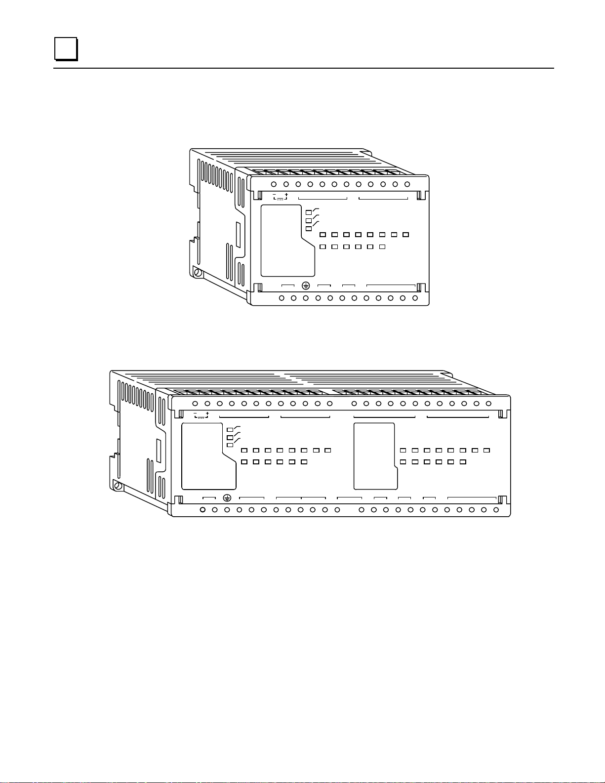
2
The Micro PLC hardware consists of a single module that includes CPU, I/O, and power supply
functions (Figure 2-1). The compact, lightweight unit is designed for 35mm DIN rail or panel
mounting.
a45452
24 VDC OUT
100-240VAC
LH
Typical 14-Point Mi cro PLC
24 VDC OUT
100-240VAC
PWR
OK
RUN
INPUT
12345678
OUTPUT
~
Q1 C OM 1 VC Q2 Q3 Q4
I1 I2 I3 I4 COM1
PWR
OK
RUN
INPUT
1
OUTPUT
~
Q1 COM1 Q2 COM2 Q3 Q4
COM2I5 I6 I7 I 8I1 I2 I3 I4 CO M1
COM2LH
Q5
INPUT
COM2I5 I6 I7 I8
Se rie s 9 0 Mi cro
2345678
PROGRAMMAB LE CONTROLLER
INPUT
OUTPUT
OUTPUT
COM3Q6
Q6
Q5
INPUT
910111213141516
789101112
OUTPUT
COM4Q7
Q8 COM5 Q9 COM6 Q10 Q11 CO M7
COM3
Series 90 Micro
PROGRAMMABLE CONTRO LLER
a45499
COM4I15 I16 COM4I11 I12 CO M3 I14I9 I10 I13COM3
COM7
Q12
Typical 28-Point Mi cro PLC
Figure 2-1. Series 90 Micro Programmable Logic Controll ers
2-2 Series 90™ Micro PLC User's Manual – June 1998 GFK-1065F
Page 28
Compatibility
• Logicmaster 90-30/20/Micro software(IC641SWP301, 304, 306, 307), release 8.01 or later
• Series 90-30 firmware release 5.0 and later
• Series 90-30 Hand-Held Programmer (IC693PRG300)
• Series 90 Protocol (SNP and SNPX) a nd RTU Slave protocol
• Series 90-20 PLCs (Micro PLCs with relay output – IC693UDR005/010 and UAL006 – only)
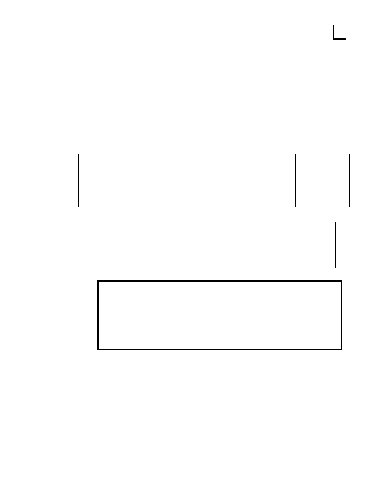
Table 2-1. Configuration/Programming Software Versions for Partial Compatibility
2
Store to
Logicmaster 90
Software Version
8.00 or later No Yes Yes Yes
5.01 or later Yes Yes Yes No
6.01 or later Yes Yes Yes No
Table 2-2. Micro to Micro Compatibility
Component Rel. 3 reads from Memcard
Program Yes Yes
Registers Yes No
Configuration Yes No
Micro Rel. 2
or Earlier
Written by a Rel. 2 Micro
Store to
Micro Rel. 3
or Later
Load from
Micro Rel. 2
or Earlier
Rel. 2 reads from Memcard
Written by a Rel. 3 Micro
Load from
Micro Rel. 3
or Later
Instructions and Function Blocks
The Series 90 Micro PLC supports most 90-30 instr uction functions and function blocks.
Detailed descriptions and examples of the use of these instructions can be found in the
Logicmaster 90-30/20/Micro Programming Software User’s Manual
30/20 Programmable Controllers Reference Manual
Programmer, Series 90-30/20/Micro Programmable Controllers User’s Manual (
(GFK-0467), and
(GFK-0466),
Hand-Held
Series 90-
GFK-0402).
See Appendix A for a list of instructions supported by the Series 90 Micro PLC.
GFK-1065F Chapter 2 Introduction 2-3
Page 29
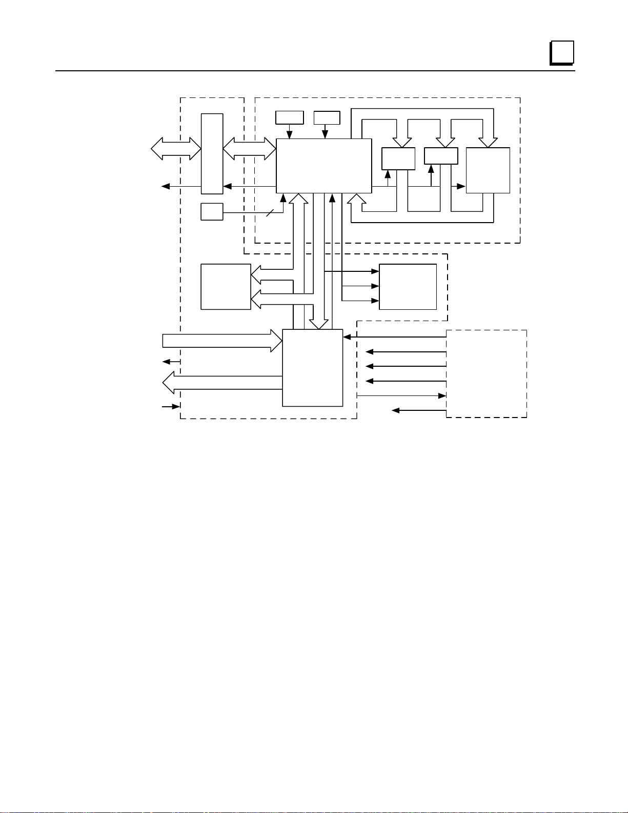
2
Functional Description
The Micro PLC contains a CPU circuit board, an I/O board, and a Power Supply board. Figure 2-2
provides an overview of Micro PLC inputs and outputs and of the functions performed by each
circuit board.
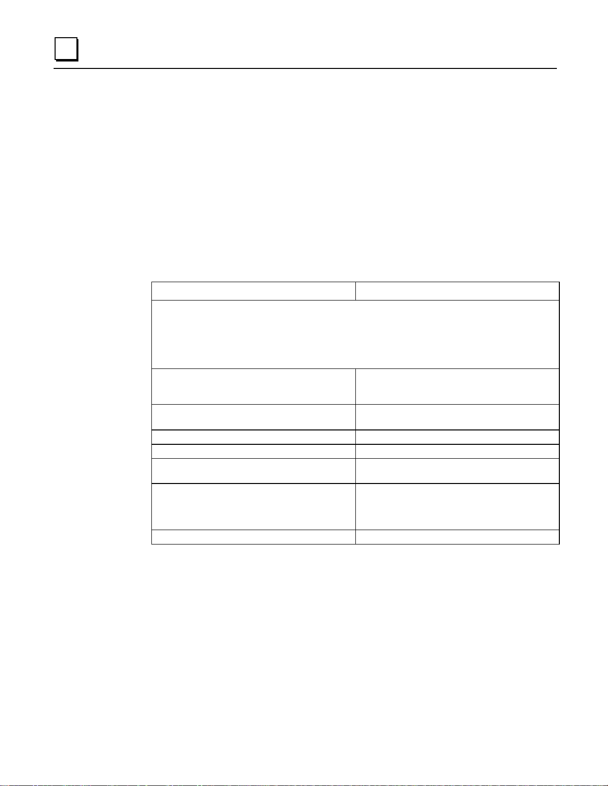
CPU Board
The CPU contains and executes the user program and communicates with the programmer (HHP
or computer runn in g Logicmaster 90-30/90-20/Micro software). The primary capabilities of the
Micro PLC CPU h ardware are listed in Table 2-3
Table 2-3. CPU Capabilities
512K x 8 sectored flash memory for operating
system and nonvolatile user program storage (3K
words of user flash memory)
32 Kbyte RAM backed by super cap (provides data
retention for 3–4 days with the power off at 25°C)
Maximum User Program - 3K words Maximum User Program – 6K words
Registers - 256 words Registers – 2K words
Typica l Sca n Rate: 1. 8 ms/K of l ogic (Boolea n
contacts)
An RS-422 serial port that supports SNP, SNPX and
RTU S lave prot ocols
14-Point Micro PLCs 23 and 28-Point Micro PLCs
H8/3003 microprocessor running at 9.84Mhz
Powerup reset circuit
Interrupt for power fail warning (2.0 ms)
Internal Coils - 1024
Four configurable 5Khz HSCs
256K x 16 sectored flash memory for operating
system and nonvolatile user program storage (6K
words of user flash memory)
64 Kbyte RAM backed by lithium battery
Real time clock backed up by lithium battery
Typica l Sca n Rate: 1. 0 ms/K of l ogic (Boolea n
contacts)
Two RS-422 serial ports: Port 1 supports SNP/SNPX
slave protocols; Port 2 supports SNP/SNPX Slave
and Mas ter pr otocols and RTU S lave protocol. (P ort
2 does not support the HHP.)
Ability to support up to four expansion units
2-4 Series 90™ Micro PLC User's Manual – June 1998 GFK-1065F
Page 30
Hand-held
Program mer
SNP
Port
Clock Reset
Microprocessor
Flash
Memory
control
RAM
2
a45683
Parallel
Expansion
Port
24 V DC
In put Powe r
Pots.
INPU T
LEDs
OUTPUT
IN P U T
OUTPUT
2
Inp uts
Outputs
PSOK
RUN
I/O C irc uits
Figure 2-2. Micro PLC Functional Block D i agram
OK
PWR
RUN
OK
24 VD C for O utp uts
24 V D C for Inp uts
CPU Board
LEDs
PSOK
5 VDC
In p u t P o w e r
5.14 VD C
Power Supply Boar dI/O Board
GFK-1065F Chapter 2 Introduction 2-5
Page 31

2
High Speed Counters
(IC693UDR011/002/005,
IC693UAL006, IC693UDR010)
The high speed counter (HSC) function consists of four built-in counters. Each counter provides
direct processing of rapid pulse signals up to 5Khz for industrial control applications such as:
meter proving, turbine flowmeter, velocity measurement, material handling, motion control, and
process control. Because it u s es dir ect process ing, the HSC can s ense input s , count, and respond
with outputs without needing to communicate with the CPU.
The HSC function can be configured to operate in one of two modes:
A4 – four identical, independent, simple (type A) counters that can count up or down
B1–3, A4 – counters 1–3 configured as one type B counter; counter 4 as one type A counter.
In ei ther mode, each counter can be enabled independently. Type A counters can be configu red for
up or down counting (default is up) and for positive or negative edge detection (default is
positive).
The HSC function is configured using the Series 90-30 and 90-20 Hand-Held Programmer or the
Logicmaster 90-30/20/Micro software configurator function. Many features can also be configured
from an application program using the COMM_REQ functi on block.
Type A Counters
A type A counter a ccepts a cou nt i nput th at increment s a 16 bit accumulator. It also accepts a
preload/strobe input that can either preload the counter accumulator with a user-defined value
(PRELOAD mode) or str obe th e a ccumu lator (STROBE mode) into a 16-bit register.
The four type A counters provide 15 words of %AI data or 16 bits of %I data to the PLC. They
receive 1 6 bi ts of %Q data from the PLC. Each counter has two discrete inputs and one discrete
output.
Type B Counter
The type B counter provides an AQUADB counting function. An AQUADB input consists of two
signals (designated A and B). A count occurs for each transition of
the phase relationship between A and B to determine count direction.
either A or B
. The counter u ses
DC Output (IC693UDR005/010, UAL006)
The high -speed DC output (%Q1) can be configured for PWM, pulse train, or HSC output.
Counter channel 1 can be configured for only one of these outputs at a time. Because AQUADB
counting uses channels 1–3, the PWM and pulse train outputs are not available when a type B
count er is configured.
PWM Output
The frequency of the PWM output (19hz to 2Khz) is selected by writing a value to memory
location %AQ2. A PWM duty ratio (the amount of time that the signal is active compared to the
signal period) within the range of 0 to 100% can be selected by writing a value to memory
location %AQ3.
2-6 Series 90™ Micro PLC User's Manual – June 1998 GFK-1065F
Page 32

I/O Board
2
Pulse Output
The frequency (10h z to 2Khz) of the pulse train is selected by writing a value to memory location
%AQ123. The number of pulses to be output (0 to 32767) is selected by writing a value to memory
location %AQ124.
ASCII Output (IC693UDR005/010, UAL006)
This feature allows you to send a specified byte string out the serial port by including a
COMM_REQ (Communications Request) instruction in a ladder diagram. The Micro PLC can
automatically send a message to a remote location that has the ability to display an ASCII string,
such as a pager. As an example of how pager enunciation could be used, when a specific alarm
condition is detected by the PLC, the PLC would execute a COMM_REQ instru ct i on to autodial
the modem attached to the serial port. If the autodial COMM_REQ is successful, a second
COMM_REQ would be executed to send an informative ASCII string to the pager where it can be
viewed by the user. Finally, a third COMM_REQ would be sent to hang up the pager .
The I/O board provides the interface to the front panel input, output, a nd power supply
conn ections for th e Micro PLC .
Input Circuits
DC Input Circuits (IC693UDR001/ 002/005/010, UAL006)
The DC input circuits condition and filter 24 VDC input voltages so that they can be properly
detected by the CPU module. The input points can be used in either positive or negative logic
mode.
The DC inputs can be used as regular in put s or to supply count and preload/strobe inputs for
HSCs. For more details on the operation of HSCs see Chapter 6.
AC Input Circuits (IC693UAA003/007)
The A C input circuits accept 120 VAC, 50/60 Hz signals. Input characteristics are compatible
with a wide range of user-supplied input devices, such as pushbuttons, limit switches, and
electronic proximity switches.
Potentiometer Inputs (All Models)
Two potentiometers are provided to allow adjustment of the values in analog registers %AI16 and
%AI17. The potentiometers can be turned by inserting a small screwdriver through an acces s hole
in the Micro PLC front panel (see Figure 2-3.)
A potential use for the potentiometers would be to set threshold values for use in logical
relationships with other inputs/outputs.
GFK-1065F Chapter 2 Introduction 2-7
Page 33

2
Output Circuits
Relay Output Circuits (IC693UDR001/ 002/005/010, UEX011, UAL006)
The 2-amp, isolated, normally open output circuits allow the low-level signals from the CPU
module to control relay devices. There is no fusing on relay outputs. The user should provide
external fusing to protect the outputs. The outputs can be configured as regular outputs or as
outputs controlled by the HSCs.
AC Output Circuits (IC693UAA003/007)
The AC output points provide 120/240 VAC, 50/60 Hz, 0.5 A signals.
DC Output (IC693UDR005/010, IC693UAL006)
The DC output circuit provides a 24 VDC output voltage. This output can be used as a normal DC
output, HSC-controlled output, pulse train output, or pulse width modulation (PWM) output.
Analog I/O (IC693UAL006)
The 23-point Micro PLC features two analog input ch a nnels that ma p t o %AI0018 and %AI0019
in the PLC. In voltage mode, the analog-to-digital (A/D) range of 0—32,000 counts corresponds
to a 0—10 V input signal. In 0—20mA current mode, th e A/D range of 0—32,000 counts
corresponds to a 0—20mA input signal. In 4—20mA current m ode, the A/D r ange of 0—32,000
counts corresponds to a 4—20mA input signal.
The analog output channel maps to %AQ0012. In voltage mode, the output channel digital-toanalog (D/A) ran ge of 0 to 32,000 counts corresponds to a 0—10V output. In 0—20mA curr en t
mode, a range of 0 to 32,000 counts corresponds to a 0—20mA output signal. In 4—20m A
current mode, the A/D ra nge of 0—32,000 counts corresponds to a 4—20mA output signal.
2-8 Series 90™ Micro PLC User's Manual – June 1998 GFK-1065F
Page 34

Input/Output Connectors
Serial Po rts
Port 1 on the Micro PLC is intended to be used as the programmer serial port. A second RS-422
compatible serial port, to be used by monitoring devices, is provided on 23 and 28-point Micro
PLCs.
Serial Communications P rotocols
Table 2-4. Communication Protocols Supported
2
Micro
PLCs
14-point Port 1
23-point Ports 1 and 2,
28-point Ports 1 and 2,
*Also requires the following versi ons or later hardware: IC693UDR001LP1, IC693UDR002LP1, I C693UA A003JP1,
IC693UDR005JP1, IC 693UAL 006B P1, IC693UAA 007H P1, and IC693UDR010BP1.
SNP/SNPX Slave SNP/SNPX Master* 4-Wire RTU
Slave*
not supported Port 1
All releases
Rel. 3.00 and later
Rel. 2.01 and later
Port 2
Rel. 3.00 and later
Port 2
Rel. 3.00 and later
Rel. 3.00 and later
Port 2
Rel. 3.00 and later
Port 2
Rel. 3.00 and later
2-Wire RTU
Slave*
Port 1
Rel. 3.10 and later
Port 2
Rel. 3.10 and later
Port 2
Rel. 3.10 and later
SNP/SNPX
The full set of SNP(X) Master commands, as described in “SNP-X Commands” in the
PLC Serial Communications User’s Manual
, GFK-0582, is supported on Port 2 of the 23- and 28-
point Micro PLCs.
Series 90
RTU Slave
This feature is implemented as specified in the
Manual
, GFK-0582. RTU as implemented in the Micro PLC is a subset of the Modbus™ Remote
Terminal Unit serial communications protocol. Prior to Release 3.10, RTU protocol is only
supported in the 4-wire implementation. Support for 2-Wire RTU was added in Release 3.10.
Table 2-5 lists the function codes supported by the Micro PLC.
Series 90 PLC Serial Communications User’s
GFK-1065F Chapter 2 Introduction 2-9
Page 35

2
Table 2-5. RTU Function Codes
Function Code Description
1 Read Output Table
2 Read Input Table
3 Read Registers
4 Read Analog Input
5 Force (Write) Single Output
6 Preset Single Register
7 Read Exception Status
8 Loopback Maintenance
15 Force (Write) Multiple Outputs
16 Preset Multiple Registers
17 Report Device Type
67 Read Scratch Pad Memory
For the 14 point unit, an additional feature is implemented that automatically detects whether the
configuration/programming software is attached to the Micro PLC. The firmware will auto-detect
the presence of the programmer when RTU is the active protocol, so that you only need to begin
using the configuration/programming software for a 14 point Micro to be able to communicate
with it.
Port 1 (All Models)
A 15-pin D-type, female connector on the front of the Micro PLC provides the connection to an
RS-422 compatible serial port which is used to communicate with Logicmaster 90-30/20/Micro
software, the HHP, or for general purpose communications. This port supports SNP and SNPX
protocols. On 14-point Micro PLCs, this port also supports RTU Slave protocols. The RS-422
conn ector is p rotected by an access door. Thi s port can be con fi gured usin g th e Logicmas ter 90
configuration program or the HHP, except for RTU communications, which must be configured by
a COMM_REQ function in ladder logic.
a45451
Figure 2-3. Micro PLC RS -422 Serial Port
24 VDC OUT
100-240VAC
L H
I1 I2
~
RS-422 Compatible
S erial Port
Pote ntiom ete rs
Q1
2-10 Series 90™ Micro PLC User's Manual – June 1998 GFK-1065F
Page 36

2
Port 2 (23 and 28-Point Model s)
A second RS-422 compatible serial port, also protected by an access door, is provided on 23 and
28-point Micro PLCs. This port can be used for general purpose communications using SNP,
SNPX, an d RTU Sla ve pr otocol. Serial Port 2 can also be configured as an SNP/SNPX Master
port. The following programming/configuration software features are supported through Port 2
when there is no programmer connected to Port 1:
1. The status line correctly displays current information about the PLC. If the proper folder is
selected and verified, the status line will show LOGIC EQUAL.
2. You can view any of the reference memories on the TABLES page in Logicmaster 90 and can
change individual values.
3. When ONLINE and LOGIC EQUAL are displayed in the status line, the references will be
displayed correctly when you view the progr am log ic.
4. You can set the privilege level to 1 or 2. (Privilege levels 3 and 4 can not be accessed.)
5. The PLC and IO fault tables are displayed.
6. The Time-Of-Day clock can be set and its current value displayed.
7. The RUN/STOP state of the PLC can be changed, either by pressing A
PLCRUN screen.
It is not possible to load and store programs and configuration through Port 2, because the
privilege level is restricted to level 2 by the PLC firmware. Autobaud is not supported on Port 2.
Port 2 can be configured using the Logicmaster 90 configuration software or by a COMM_REQ
function block within a ladder logic program (see “Configuring Serial Ports” in Chapter 5).
On release 3.0 and later 28-point Micro PLCs, a separate SNP ID for Port 2 can be configured
using Logicmaster 90 software release 8.00 or later. On earlier releases, Port 2 shares the SNP ID
with Port 1 a nd th e SNP ID ca n only be chang ed thr ough Port 1. (For more i nformation about the
SNP ID, refer to “Selecting SNP Con nections” and “CPU Configuration” in the
LogicmasterSeries 90-30/20/Micro Programming Software Users Manual
Communication through Port 2 may be lost (host may time out) while operations that involve
writing to flash memory, including storing the program, are being performed through Port 1.
+R or using the
LT
, GFK-0466.)
Expansion Port (23 and 28-Point Models)
A 40-pin connector is provided on the right side of the Micro PLC for connection to an expansion
unit using a short (3
must be used/substitutes are not compatible
uni ts connected in series.
Table 2-6. Expansion Unit Compatibility
) r ibbon cable (provide d wit h t he Micr o Exp an s ion Unit—
CM
). The Micro PLC can support up to four expansion
this ribbon
Micro PLCs Release
14-point not supported
23-point Rel. 3.00 and later
28-point Rel. 3.00 and later
GFK-1065F Chapter 2 Introduction 2-11
Page 37

2
Termi nal Strips
The Micro PLC module has two non-removable terminal strips. The input connections are on the
top terminal strip and the power supply and output connections are on the bottom terminal str ip.
Refer to Chapter 4 for field wiring information and diagrams.
An optional removable terminal strip (IC693ACC002) , shown in Figure 2-4, is available for
Micro PLCs. (They can be placed side-by-side on 28-point Micro PLCs.) The removable terminal
strips can be used on the top or bottom of the Micro PLC and are inserted under the existing screw
terminals.
a45652
24 VDC OUT
100-240VAC
L
PW R
OK
RUN
INPUT
1 23 4 5678
OU TPU T
~
H Q5
Q1 COM1VCQ2 Q3 Q4
24 VDC OUT
100-240VAC
INPUT
PWR
OK
RUN
INPUT
12345678
OUTPUT
Q1 C OM1 Q2 CO M2 Q3 Q4 Q6
COM2
Series 90 M icro
PROGRAMMABLE CONTROLLER
OUTPUT
INPUT
OUT PU T
COM4Q7
COM3Q6
Q5
Q8 COM5 Q9 COM6 Q10 Q 11 COM7
COM3LH
INPU T
910111213141516
7 8 9 10 11 12
OUTPUT
Series 90 Micro
PROGRAMMABLE CONTROLLER
Q12
COM7
a45653
Figure 2-4. Removable Termin al Stri ps
2-12 Series 90™ Micro PLC User's Manual – June 1998 GFK-1065F
Page 38

Status Indicators
The module contains LEDs that provide the user with a visual indication of the CPU and I/O
status.
Table 2-7. Indicators
LED Name Function
2
PWR
OK
RUN
INPUT
OUTPUT
Lighted if power is supplied to the unit and the power supply is operating correctly. Not
lighted if a power supply fault occurs or if power is not applied.
Blinks during self-diagnostics. Blinks (with RUN indicator) if a fault is detected during selfdiagnostics.
When lighted steadily, indicates that self diagnostics have all passed.
Lighted when the PLC is executing the logic program entered by th e user (RUN mode).
Blinks if a fault is detected during self-diagnostics.
These LEDs indicate the status of individual input points. If the associated LED is lighted,
the voltage at the input point is high enough to energize the input circuit. If the LED is not
lighted, the voltage is too low to energize the input circuit (see “I/O Specifications” in
Chapter 4 for thresholds). The input LEDs indicate the input status in all CPU modes:
STOP with I/O Disabled, ST OP wit h I/O Enabled and RUN (standard sweep or consta nt
sweep).
These LEDs indicate the status of individual output points. An LED is lighted wh en its
corresponding output is commanded to turn ON (for example if %Q1 = 1, OUTPUT 1 LED
will be lighted).
All output s t u rn OFF i n the ST OP wit h I/O Disa bled mode. Output s will hold last state or
the present user-commanded state in the STOP with I/O Enabled mode. In the RUN mode,
the outputs are controlled by th e ladder logic program.
Power Supply Board
The power supply converts the AC or DC input source power to voltages required for internal
circuitry. Power requir ements are listed in Tables 2-12 and 2-13.
On DC-input Micro PLCs, the power supply board also provides an isolated 24VDC supply to
power input cir cuits and user devices. (Refer to page 2-16 for maximum current loads for each
model.) These outputs do not have fuse protection. The user should provide external fuses to
prot ect th e output s.
On 23-point Micro PLCs (IC693UAL006), the power supply board provides internal 15VDC
power for the anal og output curren t l oop and a ±15VDC supply for the an a log in put and output
voltage circuits.
GFK-1065F Chapter 2 Introduction 2-13
Page 39

2
Configuration and Programming
The Micro PLC can be configured and programmed using any of the following methods.
• Logicmaster 90-30/20/Micro software on one of the following types of computers:
Workmaster™ II or a CIMSTAR™ I industrial computer
• Logic mas ter 90 Micr o s oftware with any of t he above compute rs.
• Series 90-30/90-20 Hand-Held Programmer (IC693PRG300).
Configuration and programming can be accomplished off-line from the PLC using the
Logicmaster 90 programmer. If you are using an HHP, configuration and programming can be
done on-line with the HHP attached to and interfacing with the PLC. Programming and
configuration communications must use Port 1.
®
IBM
MS-DOS compatible Personal Computer with 2 Mbyte RAM and an Intel 386 or higher
PC-AT, PS/ 2® (Personal System 2®) with 2 Mbyte RAM and an Intel 386 or
higher processor
processor
The Micro PLC provides flash memory for non-volatile user program storage and for system
firmware. The user program is always executed from flash memory. However, the Micro PLC can
be configured to read its configuration at powerup from either RAM or flash memory (ROM).
Use of the programming and configuration software is described in the Logicmaster 90-
30/20/Micro Programming Software User’s Manual, GFK-0466. The Workmaster II computer is
described in the Workmaster II PLC Programming Unit Guide to Operation Manual, GFK-0401.
Use of the HHP is described in the Hand-Held Programmer, Series 90-30/20/Micro
Programmable Controllers User’s Manual, GFK-0402.
Fault Reporting
The Micro PLC monitors internal operations for system and user problems. These faults are
reported through the %S references and through an internal fault table. Access to %S information
is available through the Logicmaster 90 software or the HHP. The fault table can only be accessed
by Logicmaster 90 software. For more details on faults and fault reporting, see Chapter 9.
2-14 Series 90™ Micro PLC User's Manual – June 1998 GFK-1065F
Page 40

Specifications
The following tables list ordering information, physical and functional characteristics, and input
power requirements for the Micro PLCs. Specifications for input and output signals are provided
in Chapter 4.
Table 2-8. I/O Point Configurations
2
Input Points
Description
14 point DC in/relay out, AC power
14 point DC in/relay out, DC power
14 point DC in/DC out, DC power
14 point AC in/ AC out, AC power
28 point DC in/relay and DC out, AC power
28 point AC in/AC out, AC power
28 point DC in/relay out, DC power
23 point analog DC in/relay and DC out, AC power 13 DC, 2 analog
14-point Expansion Unit
DC in/relay out, AC power
(points/common)*
8 DC
(4 and 4)
8 DC
(4 and 4)
8 DC
(4 and 4)
8 AC
(4 and 4)
16 DC
(4, 4, 4, and 4)
16 AC
(4, 4, 4, and 4)
16 DC
(4, 4, 4, and 4)
(4, 4, 4, and 2)
8 DC
(4 and 4)
Output Points
(points/common)* Cata log Numbers
6 relay
(1, 1, and 4)
6 relay
(1, 1, and 4)
6 DC
(6)
6 AC
(2 and 4)
1 DC, 11 relay
(1, 4, 1, 1, 1, 1, and 3)
12 AC
(2, 4, 2, and 4)
1 DC, 11 relay
(1, 4, 1, 1, 1, 1, and 3)
1 DC, 9 relay
1 analog
(1, 4, 1, 1, 1, and 1)
6 relay
(1, 1, and 4)
IC693UDR001
IC693UDR002
IC693UDD004
IC693UAA003
IC693UDR005
IC693UAA007
IC693UDR010
IC693UAL006
IC6963UEX011
*See Chapter 4 for fusing information.
Accessories
Description Catalog Numbers
Series 90 Micro PLC Programming Software, Cable Kit, and manuals IC640HWP300
Hand-Held Programmer with Cables and Manual (includes IC693CBL303) IC693PRG300
Hand-Held Programmer Memory Card IC693ACC303
Logicmaster 90 Software (software only) IC641SWP300
Removable Terminal Strip IC693ACC002
Expansion Unit Cable IC693ACC003
GFK-1065F Chapter 2 Introduction 2-15
Page 41

2
Table 2-9. Physical and Functional Characteristics (14-Point PLCs)
Weight:
IC693UDR001/002/UAA003/UEX011 0.86 lbs (390 g)
Module Dimensions
Typical Scan Rate
Maximum number of Discrete Physical I/O Points
Maximum number of slave devices per network
Output Power Supplie s
IC693UDR001/002/UEX011
Super cap backup for RAM
Height: 3.2” (82mm)
Depth: 3.0” (76mm)
Width: 4.5” (115mm)
1.8 ms/K of logic (Boolea n cont acts )
14 (8 inputs/6 outputs)
8 (can be increased with a repeater)
24VDC for input circuits & user devices, 100mA max.
+5VDC on pin 5 of Serial Port, 155mA max (for UDR001/002
only)
Provides data retention for 3–4 days with the power off at 25°C.
Table 2-10. Physical and Functional Characteristics (28-Point PLCs)
Weight IC693UDR005
IC693UAA007
IC693UDR010
Module Dimensions
Typical Scan Rate
Real Time Clock accuracy
10°C
25°C
55°C
Maximum number of Discrete Physical I/O Points
Maximum number of slave devices per network
+24 VDC Output Power Supply (IC693UDR005/010)
(for input circuits and user devices)
+5 VDC on pin 5 of Serial Ports
Serial Port 1
Serial Port 2
Serial Ports 1 & 2 combined
Lithium battery lifetime
1.5 lbs (680 g.)
1.54 lbs (700 g.)
1.54 lbs (700 g.)
Height: 3.2” (82mm)
Width: 8.6” (218mm)
Depth: 3.0” (76mm)
1.0 ms/K of logic (Boolea n cont acts )
4.54 sec./day
5.22 sec./day
10.66 sec/day
28 (16 inputs/12 outputs)
8 (can be increased with a repeater)
200 mA maximum
155mA maximum
100mA maximum
255mA maximum (The load on either port can exceed the
individual ratings listed above, if the combined load does not
exceed 255mA.) See “Caution” below.
Shelf life (powered down)
Up to 7 years typical at 30 °C
Up to 5 years typical at 55 °C
Caution
If you are using loads greater than the individual current ratings for the
+5VDC supply on pin 5 of Port 1 or Port 2, oper at or i nt e rface de vices must
be connected and disconnected with the power to the Micro PLC off. (This
precaution is not necessary if the loads on both ports are less than their
individual current ratings.)
2-16 Series 90™ Micro PLC User's Manual – June 1998 GFK-1065F
Page 42

Table 2-11. Physical and Functional Characteristics (23-Point Micro PLC, IC693U AL006)
Weight
Module Dimensions
Typical Scan Rate
Real Time Clock accuracy
10°C (with internal 15 °C rise)
25°C (with internal 15 °C rise)
55°C (with internal 15 °C rise)
Maximum number of Discrete Physical I/O Points
Maximum number of slave devices per network
+24 VDC Output Power Supply
(for input circuits and user devices)
+5 VDC on pin 5 of Serial Ports
Serial Port 1
Serial Port 2
Serial Ports 1 & 2 combined
Lithium battery lifetime
Analog inputs
Input ranges 0 to 10 V (10.24V maximum)
Resolution: 0 to 10 V range
0 to 20 mA range
4 to 20 mA range
Accuracy 1% of full scale over full operating temperature range
Lin earity ±3 LS B maxim um
Common mode voltage 200 V maximum
Filter response time
Analog outpu ts
Output ranges 0 to 10V (10.24V maximum)
Resolution 12 bits over 0 to 10V range (1 LSB = 2.5mV)
Accuracy ±1% of full scale over full operating temperature range
1.52 lbs (690g)
Height: 3.2” (82mm) Width: 8.6” (218mm) Depth: 3.0”
(76mm)
1.0 ms/K of logic (Boolea n cont acts )
4.54 sec./day
5.22 sec./day
10.66 sec/day
23 (13 inputs/10 outputs)
8 (can be increased with a repeater)
200 mA maximum
155mA maximum
100mA maximum
255mA maximum (The load on either port can exceed the
individual ratings listed above, if the combined load does not
exceed 255mA.) See “Caution” below.
Shelf life (powered down)
Up to 7 years typical at 30 °C
Up to 5 years typical at 55 °C
Two, differential
0 to 20 mA (20.5mA maximum)
4 to 20 mA (20.5mA maximum)
10 bits (1 LSB = 10mV)
9 bits (1 LSB = 40µA)
8+ bits (1 LSB = 40µA)
20.2ms to reach 1% error for step response
1, single-ended, non-isolated
0 to 20mA (20.5mA maximum)
4 to 20mA (20.5mA maximum)
12 bits over 0 to 20mA range (1 LSB = 5µA)
11+ bits over 4 to 20mA range (1 LSB = 5µA)
(0°C to 55°C)
2
Caution
If you are using loads greater than the individual current ratings for the
+5VDC supply on pin 5 of Port 1 or Port 2, oper at or i nt e rface de vices must
be connected and disconnected with the power to the Micro PLC off. (This
precaution is not necessary if the loads on both ports are less than their
individual current ratings.)
GFK-1065F Chapter 2 Introduction 2-17
Page 43

2
Table 2-12. AC Power Requirements
AC Power Requirements – (IC693UDR001, IC693UAA003/007, IC693UDR005, IC693UEX011)
Range 100 -15% to 240 +10% VAC
Frequency 50 -5% to 60 +5% Hz
Hold-up 10 ms at 85 VAC
Inrush Time 2 ms for 40 A
Inrush Current 14-point Micro PLCs and
14-point Micro Expansion Unit
28-point Micro PLCs 30 A maximum at 200 VAC
Input Current 14-point Micro PLCs 0.12 A typical at 200 VAC
28-point, DC In/Relay Out
Micro PLCs
28-point, AC In/AC Out
Micro PLCs
Input Power Supply Rating UDR001 35 VA
UAA003 20 VA
UAA007 25 VA
UDR005 40 VA
UEX011 35 VA
AC Power Requirements – (IC693UAL006)
Range 100 -15% to 240 +10% VAC
Frequency 50 -5% to 60 +5% Hz
Hold-up 10 ms at 85 VAC
Inrush Time 2 ms for 40 A
Inrush Currents 35 A maximum at 200 VAC
Input Current 0.35 A typical at 100 VAC
Isolation 1500VAC rms field side to logic (both power supply input and 24
Input Power Supply Rating 50 VA
18 A maximum at 120 VAC
30 A maximum at 200 VAC
40 A maximum at 265 VAC
40 A maximum at 265 VAC
0.25 A typical at 100 VAC
0.26 A typical at 100 VAC
0.12 A typical at 200 VAC
0.16 A typical at 100 VAC
0.09 A typical at 200 VAC
46 A maximum at 265 VAC
0.22 A typical at 200 VAC
VDC power supply output)
2-18 Series 90™ Micro PLC User's Manual – June 1998 GFK-1065F
Page 44

Table 2-13. DC Power Requirements
DC Power Requirements – (IC693UDR002/010)
Range 14-point Micro PLC 12 -15% to 24 +25% VDC
12 -15% to 24 +10% VAC
28-point Micro PLCs 24 -20%, +25% VDC
24 -15%, +10% VAC
Hold-up 14-point Micro PLCs 4 ms at 10 VDC
10 ms at 12 VDC
28-point Micro PLCs 2ms at 9.5 VDC
Inrush Current 14-point Micro PLC 65 A maximum at 24 VDC
81 A maximum at 30 VDC
28-point Micro PLC
Inrush Time 14-point Micro PLC 10 ms for 81 A
28-point Micro PLC 10 ms for 81 A
Input Current 14-point Micro PLC
28-point Micro PLC 1.4 A typical at 24 VDC
Input Power Supply Rating UDR002 15 W
UDR010 20 W
1
2
65 A maximum at 24 VDC
81 A maximum at 30 VDC
0.4 A typical at 24 VDC
0.8 A typical at 12 VDC
2
Notes
1. If configured to disable powerup diagnostics, the 28-point DC In / Relay Out/DC Power unit (IC693UDR010)
will begin logic solution 100ms after the voltage level of the power supply input reaches and maintains 24VDC.
The 24VDC power source for the UDR010 unit must have enough transient curr ent capability to support the
inrush current of the power supply and maintain a 24VDC voltage level (see power supply specifications for
inrush req uireme nt s above).
2. The DC power supply requires more current at startup voltage (approximately 4 VDC) than at rated input
voltage. A minimum of 2.0 A is necessary to start up the DC power supply.
GFK-1065F Chapter 2 Introduction 2-19
Page 45

2
Table 2-14. Environmental Requirements
Operating temperature 0 to 55 °C
Storage temperature -40 °C to 85 °C
Relative humidity 5% to 95%
Table 2-15. Mem ory A l location
Type 14-Point Micro PLCs 23 and 28-Point Micro PLCs
Application Program 3K words 6K words
%R 256 words 2K words
%AI 128 words 128 words
%AQ 128 words 128 words
%I 512 bits 512 bit s
%Q 512 bits 512 bits
%G 1280 bi t s 1280 bits
%M 1024 bits 1024 bits
%T 256 bits 256 bits
%S 128 bits 128 bits
For a list of reserved memory locations, refer to Appendix B.
2-20 Series 90™ Micro PLC User's Manual – June 1998 GFK-1065F
Page 46

Chapter
Installation
3
This chapter describes the procedures for installing the Micro PLC and preparing the system for
use. Included in this chapter are instructions for unpacking, inspecting, and installing the Micro
PLC. Instructions are also provided for connecting cables to programming devices.
Minimum Hardware Requirements
To install and set up the Micro PLC, you will need:
• Micro PLC Module.
• Programming device (this can be one of the following items):
A. Hand-Held Programmer and cable.
B. Logicmaster 90-30/20 Micro software (or Logicmaster 90 Micro software), a Workmaster
II or CIMSTAR I industrial computer, or an IBM AT, PS/2 or other MS-DOS compatible
Personal Computer (with 386 or high er m icr oprocessor and 2 Mbyte memory) and
appropriate cables.
Unpacking
• Tools for mounting the Micro PLC and connecting field wiring.
If the PLC is to be programmed using Logicmaster 90 software, a Workmaster II, CIMSTAR I, or
an IBM or IBM-compatible computer is required. Logicmaster 90 software can use a Work Station
Interface (WSI) board, an RS-422 port, or a sta ndard RS-232 interface with an RS-422 to RS-232
converter. The WSI board is installed in the Workmaster II computer at the factory.
1. Visual inspect i on. Upon recei vi ng your Micro PLC system, carefully inspect all shipping
containers for damage that may have occurred during shipping. If any part of the system is
damaged, notify the carrier immediately. The damaged shipping container should be saved as
eviden ce for inspection by the carrier.
It is your responsibility to register a claim with the carrier for damage incurred during
shipment. However, GE Fanuc will fully cooperate with you, if such action is necessary.
2. Unpacking. Unpack all shipping cartons and verify the contents. All shipping containers and
packing material should be saved in case it is necessary to transport or ship any part of the
system.
3. Pre-installation Check. After unpacking the Micro PLC, record all serial numbers. These
serial numbers will be required if you need to request product service during the warranty
period of the equipment.
GFK-1065F 3-1
Page 47

3
Instal lation Requirements
The Micro PLC should be installed in a location that meets the environmental requirements listed
on page 3-20. For best performance of your Micro PLC, the installation location should also
adhere to the following guidelines:
• The temperature must not change so rapidly that condensation could form on or inside the
unit.
• No combustible gases.
• No dust, salty air, or conductive materials (iron powder, etc.) that could cause internal shorts.
• If possible, do not install the Micro PLC wh ere it will be exposed to direct sunlight.
• Provide adequate ventilation space. Recommended minimum space allowances are
approximately: 50mm (2 inches) top, sides and bottom. See Figures 3-1 through 3-3.
• Do not install the Micro PLC above equi pment that gen era tes a la rge amou nt of hea t.
• If the am bi ent t emperature exceeds 5 5 °C, p rovide a ventilation fan or air conditioner.
Installation
• Do not install the Micro PLC within 200mm (8 inches) of any high voltage (more than
1000V) or high current (more than 1A) line (except for outputs controlled by the Micro PLC).
• For ease of maintenance and safety, locate the Micro PLC as far away from high voltage
equipment and power generation equipment as possible.
• For r ecom mended field wiring practices, refer to “Gener al Wiring Pr oced u res” i n Chapt er 4.
The Micro PLC can be mounted on a wall or panel using screws, or on a 35 mm DIN rail. The
Micro PLC must be mounted on a vertical surface. Do not mount it on a horizontal surface. (See
Figures 3-1 through 3-3 for recommended mounting orientation and spacing requirements.)
a45442
Im proper Mou ntingProper Mounting
Figure 3-1. Recommended Mounting Orientations for the Mi cro PLC
3-2 Series 90™ Micro PLC User's Manual – June 1998 GFK-1065F
Page 48

Detail Of Disen gaged Clip
y
Minim um Allowan ce For Cooling
*
3
a45436
.35
(9)
.59
(15)
1.00
(25)
.14
(3.5)
*
3.24
(82.3)
1.99
(50 )
4.53
(115)
4.21
(107)
.16
(4 )
2.99
(76)
SIDE VIEW
.55
(14)
Dim e n s io ns in in c he s . M i llim e te r s a re in p ar e nt h es is .
.16
(4)
.59
(15)
FRONT VIEW
Figure 3-2. Micro PLC Mounting Di m ensi ons and Spaci ng Requi rem ents, 14-Point
D eta il Of D isengaged C lip
Minimum A llowance For Cooling
*
.35
(9)
.59
(15)
1.00
(25)
.14
(3.5)
*
1.99
(50)
8.58
(218)
8.26
(210)
1.99
*
.1 6
(4 )
.18 Dia.
(4.5)
(Typical)
.14
(3.5)
(50 )
*
.16
(4)
.16
(4)
1.99
(50)
1.99
*
(5 0)
2.93
(7 4.3 )
1.99
*
(5 0)
a45418
1.99
*
(50 )
.18 Dia.
.1 6
(4.5)
(T
pical)
.14
(3.5)
(4)
2.93
(74.3)
1.99
*
(50 )
2.99
(76)
SIDE VIEW
.55
(14)
3.24
(82.3)
.16
(4)
.1 6
(4)
Dimensions in inches. Millimeters are in parenthesis.
.59
(15)
FRONT VIEW
.59
(15)
Figure 3-3. Micro PLC Mounting Di m ensi ons and Spaci ng Requi rem ents, 23 and 28-Point
GFK-1065F Chapter 3 Installat ion 3-3
Page 49

3
gag
gag
Mounting a Unit on a DIN Rail
The method of mounting a Micro PLC unit on a 35 mm DIN rail is shown below. A small clip on
the back of the unit holds it in place on the rail.
DIN
Rail
(Retracted)
Tab
Clip
a45440
DIN
Rail
Tab
(En
ed)
Clip
Position the upper edge of the unit over
the DIN rail, so that the rail is behind the
tab as shown above. Pull the clip down.
Removing a Unit From a DIN Rail
To remove a unit from a DIN rail, follow the procedure shown below.
DIN
Rail
Tab
(En
ed)
Clip
Pivot the unit downward (for a unit being mounted
right side up) until the unit is over the DIN rail.
Press the clip firmly into place.
a45441
DIN
Rail
Tab
Clip
(Retracted)
Pull clip at the bottom of the unit down until it is
disengaged from the DIN rail.
3-4 Series 90™ Micro PLC User's Manual – June 1998 GFK-1065F
Pivot the unit away from the
rail.
Page 50

Grounding Procedures
g
Equipment grounding recommendations and procedures are listed below. These grounding
procedures must be properly followed for safe operation of your Micro PLC system.
• The maximum r ecommended resistance to ground is 200mΩ (equivalent to 100 feet of AWG
#12 – 3.29mm2 – copper cable).
• Grounding installation must conform to National Electrical Code (NEC) standards.
• Ground conductors should be connected with separate branches routed to a central earth
ground point. This method is shown in the figure below.
• Ground conductors should be as short and as large in size as possible. Braided straps or
ground cables – AWG #12 (3.29mm2) or larger – can be used to minimize resistance.
Conductors must always be large enough to carry the maximum short circuit current of the
path being considered.
Programm in
Device
Series 90 Micro
PLC
3
a45684
Motor Drives Mac hinery
an d
other
Electrical
Control
Equipment
Figure 3-4. Recommended System Grounding
Logicmaster Programming Device Grounding
For proper operation, the programmer for Logicmaster 90 Micro softwar e (Workmaster II or
CIMSTAR I, or IBM-PC or compatible computer) must have a ground connection in common
with the Micro PLC. Normally, this common ground connection is provided by ensuring that the
programmer’s power cord is connected to the same power source (with the same ground reference
point) as the Micro PLC, but this will n eed to be verified for each installation.
I/O Installation and Wiring
Wiring connections to and from user-supplied input and output field devices are terminated at two
terminal strips on the Micro PLC front panel. I/O connections are defined on the Micro PLC front
panel. Wiring diagrams are provided in the “Field Wiring” section of Chapter 4.
Earth Central
Ground PointGround
NOT E
Signal and power
conn ections
not show n
GFK-1065F Chapter 3 Installat ion 3-5
Page 51

3
Powerup Self-test
After the p roper p ower connections have been made, the Micro PLC can be power ed u p to veri fy
that the unit is installed correctly.
Normal Powerup Sequence
Apply the required power to the power inputs.
• The Power in dicator, labeled PWR, should light.
• The CPU status indicator, labeled OK, blinks during the power-up self diagnostics. When
Warning
Ensure that the protective cover is installed over terminals on the terminal
board when power is applied to the unit. The cover protects against
accidental shock hazard which could cause severe or fatal injury to the
operator or maintenance personnel.
self-diagnostics have been successfully completed, the OK indicator will remain lighted. (The
Micro PLC can be configured to power up without running diagnostics. Unless your
application requires fast power up, it is recommended that you leave powerup diagnostics
enabled. For configuration information, refer to Chapter 5.)
• The CPU status indicator, labeled RUN, should light if the unit is configured to run on power-
up.
• If any of the input points have been wired to field devices that energize those circuits and the
RUN indicator is lighted, the corresponding input LEDs should light.
• If the RUN indicator is not lighted, all output indicators should be dark (in the STOP with I/O
Disabled mode).
After verifying that a valid power-up sequence has occurred, attach a programming device (HandHeld Programmer or computer with Logicmaster 90 software) to configure the Micro PLC and
develop programs for the unit.
Caution
During a gradual power down, when the input power supply voltage is
below the minimum operating voltage, the Micro PLC may power off and
then power on again until the input voltage drops low enough to prevent
power on again. You should take precautions if this type of behavior cannot
be tolerated in your application.
3-6 Series 90™ Micro PLC User's Manual – June 1998 GFK-1065F
Page 52

Fast Powerup
Powerup diagnostics can be disabled using the Logicmaster 90 configuration software. Unless
your application requires unusually fast powerup, it is recommended that you leave this feature
enabled. Disabling powerup diagnostics has the following effects:
The I/O Link Interface Expansion Unit will not work.
No expansion units can be used. (If expansion units are connected while powerup diagnostics
are disabled, faults will be logged in the I/O tables.)
All HHP key sequences will be ignored when the Micro PLC is powering up.
Table 3-1. Powerup Times with Powerup Diagnostics Di sabl ed
Model Time
28-point units
IC693UDR010 100ms
IC693UDR005/UAA007 300ms (typical)
All 14-point units 350ms (typical)
3
Error Det ection And Correc t ion
If the Micro PLC fails the power-up self-test, one of the conditions listed in Table 3-2 will be
observed after applying power.
Table 3-2. Powerup Sequence Troubleshooting
Symptom Action
PWR indicator does not light. 1. Check that the proper power source is provided and is
on.
2. With power supply off, check wiring to the module unit
to be sure it is connected correctl y.
PWR indicator lighted but OK indicator is
not lighted.
PWR indicator on, but OK and RUN
indicators are blinking.
(This indicates that the power source is good and that the
CPU has detected an internal fault.)
Refer to “Powerup Diagnostics” in Chapter 9.
The Micro PLC features built-in blink codes to assist in
troubleshooting. For definitions, refer to “Powerup
Diagnostics” in Chapter 9.
GFK-1065F Chapter 3 Installat ion 3-7
Page 53

3
Connecting a Programming Device
The Micro PLC can be programmed and configured using either the HHP or the Logicmaster 90
software (included in IC640HWP300). Both of these methods are described in Chapter 5.
An RS-422 compatible serial port is provided on the front of the Micro PLC for communication
with Logicmaster 90-30/20/Micro software or the HHP. This port can also be used for general
purpose communications using the Series 90 Protocols (SNP and SNPX). On 14-point Micro
PLCs, this port can also be used for RTU Slave communications.
A second RS-422 compatible port (Serial Port 2) is provided on 28-point Micro PLCs. This port
can be used for general purpose communications using SNP, SNPX and RTU Slave. It is not
possible to load and store programs and configuration through Port 2, because the privilege level
is restricted to level 2 by the PLC firmware. Communications through Port 2 may be lost (host
may time out) while operations that involve wr iting to flash memory, including storing the
program, are being performed through Port 1.
For additional information on the functions of the serial ports, refer to “Serial Ports” in Chapter 2.
For serial port orientation and pinouts, see Appendix D.
Connecting the Hand-Held Programmer
The Hand-Held Programmer (IC693PRG300) is a compact programming device that connects to
the Micro PLC 15-pin serial port through a 6 foot (1.83 meter) cable that conforms to the RS-485
specification.
G E F a n u c
SERIES 90-30
PROGRAMMABLE
CONTROLLER
LD
AND D ORE NOT
A
I
A I
7 8 9 R
4 5 6
1 2 3
0
HAND HELD PROGRAMMER
TMR
RSTM
SETM
OUT
OUTM
B
AQ
SET
F
C
Q
M
T
RST
BLK
G
S
ONDTR
UPCTR
DNCTR
FUNC DEL
#
WRITE
READ
VRFY
HEX
CLR
DEC
MODE
RUN
SRCH
INS
ENT
a43052
SLOT FOR
MEMORY
CARD
SERIAL PORT CONNECTOR
TO CPU SERIAL PORT
Figure 3-5. Hand-Held Programmer
3-8 Series 90™ Micro PLC User's Manual – June 1998 GFK-1065F
Page 54

3
Warning
Always connect the cable to the Hand-Held Programmer first, then connect
the cable to the Micro PLC. This avoids any chance of shorting the +5 volt
supply on the PLC which could cause incorrect operation of the Micro PLC.
Incorrect operation of the PLC could damage the equipment or cause
personal injury to an operator.
To connect the Hand-Held Programmer cable:
• Attach the 15-pin male D connector on one end to the mating 15-pin female D connector on
the Hand-Held Programmer.
• Attach the connector on the other end of the cable to the RS-422 connector on the Micro PLC
(Port 1 on the 28-point Micro PLC). These connections are shown in Figure 3-6.
Note
Port 2 on the 28-point Micro PLC does not support the HHP. You must connect
the HHP to Port 1.
a45438
Hand-H eld
Program m er
(IC693PRG300)
Series 90
Micro PLC
Cable (IC693CBL303)
Figure 3-6. Hand-Held Programmer Cable Connection to a Micro PLC
GFK-1065F Chapter 3 Installat ion 3-9
Page 55

3
Connections for Using Logicmaster 90-30/20/Micro Software
You need a Software and Cable Kit package (IC640HWP300) to use Logicmaster 90 Micro
software with the Micro PLC.
Workmaster II Computer with WSI
The cable connection for this configuration is from the connector on the WSI board
(IC647WMI920) to the Micro PLC serial port as shown below.
Serial Cable
WSI
Serial
(IC647CBL704)
a45445
Series 90
Micro PLC
Wo rk m a st er II
Figure 3-7. Logicmaster 90 Micro Programmer Connection through a WSI
lBM-PC Compatible Computer
This configuration uses a standard RS-422 or RS-232 serial communications port on the IBM-PC
compatible computer. An RS-422/RS-232 miniconverter (IC690ACC901) is required. Examples
of cable connections for thi s type of interface are shown in Figure 3-8. Refer to Appendix E,
“Converters” for a complete description of the miniconverter.
3-10 Series 90™ Micro PLC User's Manual – June 1998 GFK-1065F
Page 56

3
IB M P C (XT ) ,
Workmaster
IB M P C (A T )
IB M P S /2 ,
Workmaster II
RS-232 RS-422
IC690CBL701
10 Feet
(3 Me ters)
RS-232 RS-422
IC690CBL702
10 Feet
(3 M ete rs)
a45446
Series 90
Micro PLC
RS485/RS232
Converter
IC690A CC901
a45447
Series 90
Micro PLC
RS485/RS232
Converter
IC690ACC901
a45448
Series 90
Micro PLC
RS-232 RS-422
IC690CBL705
10 Fe et
(3 M eters )
IB M C o m p at ib le
With RS -4 22 Inter fac e
(See 15 pin connector assignment)
Figure 3-8. Examples of Serial Connection from Series 90 Micro PLC to Computer
RS485/RS232
Converter
IC690ACC901
Series 90
Micro PLC
RS-422
a45449
GFK-1065F Chapter 3 Installat ion 3-11
Page 57

3
Multidrop Serial Data Configuration to Series 90 PLCs
Any installation that includes PLCs over 50 feet (15.2 meters) apart must
include optical isolation.
The Series 90 Micro PLC supports a maximum of eight devices on a single serial link per
network. This number can be increased with the use of a repeater. For additional information on
serial communications, refer to the
0582.
Termination resistance for the Receive Data (RD) signal needs to be connected only on units at
the end of the line. This termination is made on the Series 90 Micro PLC products by connecting
a jumper between pins 9 and 10 inside the 15-pin D-shell. Sample cabling for multidrop
installations is provided in Appendix D, “Serial Ports and Cables” and Appendix E, “Converters.”
Series 90 PLC Serial Communications User’s Manual
Note
, GFK-
3-12 Series 90™ Micro PLC User's Manual – June 1998 GFK-1065F
Page 58

Replacing Fuses (AC In/AC Out Models Only)
Caution
There are no user-replaceable parts in the DC In/Relay Out Micro PLCs
(UDR001/002/005/010, UAL006, UEX011).
The AC In/AC Out model Micro PLCs (IC693UAA003/007) provide user-replaceable fuses for
their AC output points. Because each output fuse is on the common of several circuits, a blown
fuse will prevent the entire group associated with it from working. (Refer to Table 3-3 and to the
field wiring diagrams in Chapter 4.)
Warning
Remove power from the unit before removing field wiring or removing the
front cover. Failure to remove power from the unit before disassembling it
could cause severe or fatal injury to personnel.
3
Caution
Do not attempt to remove the circuit boards from the Micro PLC assembly,
or to replace fuses on the power supply board. Any di sa sse mbly be y ond
removing the front cover and replacing AC output fuses could damage the
unit and will invalidate the warranty.
The plug-in fuses are located on the I/O circuit board (Figure 3-9), which is located immediately
behind the Micro PLC fr ont cover. To replace these fus es:
1. Remove power from the unit and I/O devices.
2. Remove fie ld wiri ng from th e unit.
3. Remove front cover from the unit. (Gently press inward one of the tabs located on the sides of
the unit and pull the cover off.)
COM2I5 I6 I7 I8I1 I2 I3 I4 CO M1
Press tab in
24 VDC OUT
PW R
OK
RUN
INP UT
1
OUTPUT
INP UT
Serie s 90 Micro
2345 678
PROGRAMM ABLE CONTROLLER
~
100-240VAC
LH
Q1 C O M1 Q2 COM2 Q3 Q4
OUTPUT
Q5
COM3
Q6
4. Replace each blown fuse with the appropriate fuse type, listed in Table 3-3.
GFK-1065F Chapter 3 Installat ion 3-13
Page 59

CNA
ROT1
ROT2
CNP1
FUSE 1
3.2A
37
a45443
3.2A
36
FUSE2
3
CNB
14-Point Micro PLC (IC693U AA 003)
a45415
CNA
ROT1
FUSE1 FUSE2
3.2A
36
3.2A
36
CNC
CNB
ROT2
CNP
28-Point Micro PLC (IC693U AA 007)
Figure 3-9. Locations of Fuses on AC In/AC Out I/O B oard
CND
FUSE3
3.2A
36
FUSE4
3.2A
36
3-14 Series 90™ Micro PLC User's Manual – June 1998 GFK-1065F
Page 60

Caution
The fuse on the power supply board, which is located at the bottom of the
unit, is
not replaceable
and cannot be easily acc e ssed. This fuse i s pr ovided
as a safety precaution. If it blows, a fault in the power supply is indicated
and the Micro PLC should be replaced.
Note
The fuses listed below are only for the output points on the AC In/AC Out Micro
PLCs (IC693UAA003/UAA007). You can easily access thes e fu ses by rem ovi ng
the PLC front cove r.
Out Micro PLCs.
Table 3-3. List of Fuses for AC In/AC O ut I / O B oards
Micro PLC Location Output Points Controlled
IC693UAA003, IC693UAA007 FUSE 1 Q1–Q2
IC693UAA007 FUSE 3 Q7–Q8
There are no user-replaceable parts in the DC In/Relay
FUSE 2 Q3–Q6
FUSE 4 Q9–Q12
3
Table 3-4. Fuse Specifications
Current Rating
3.2 A
Catalog Number Available From
GE Fanuc: IC693ACC001
(5/package)
Third Party: Daito HM32 See “Distributors,” below*
GE Fanuc Automation N.A., Inc. – Asia Pacific Operations
No. 1 Teban Gardens Crescent
Jurong – Singapore 608919
Phone: (65) 566-9902 or (65) 566-4918
Fax: 011 (65) 567-1856 or 011 (65) 566-7703
*Distributors
U.S.A. MHOTRONICS, Inc.
960 Corporate Woods Parkway
Vernon Hills, IL 60061
Europe OESS Gmbll Frankfurt Office
Senefelder Street 1
63110 Rodgau, Germany
Singapore B.B.S. Electronics PTE. LTD
1 Genting Link, #05-03
Perfecindustrial Building
Singapore 1334
Phone: 847-9139566
Fax: 847-913-9587
Phone: 6106750313
Fax: 6106-72719
Phone: 748-8400
Fax: 748-8466
GFK-1065F Chapter 3 Installat ion 3-15
Page 61

3
Expansion Unit Installation
The 23-point Micro PLCs support the Series 90 Micro Expansion Units (IC693UEX011), Generic
(third pa rty) expansion units, and t he I/O Link Interface unit (IC693UEX013). Up to four
expansion units ca n be connected i n ser ies to a ba s e Micro PLC.
Power down the Micro PLC before connecting an Expansion Unit.
Connecting an Expansion Unit with the Micro PLC powered up will damage
the unit.
If you are connecting a third-party expansion unit, you will need to provide a
ribbon cable . Soft ware filteri n g of generic (third-party) expansion I/O is not
supported. Hardware filtering should be supplied to meet the required noise
immunity on these units.
Caution
Note
Micro Expansion Unit
The Micro Expansion Unit (IC693UEX011) connects to a 23-point Micro PLC to provide
additional I/O points (8 inputs and 6 outputs per each unit). This expansion unit has the following
features:
• Ribbon c able for conn e ction to 28-poin t Micro PLC is provided with expansion unit. T his
• The Micro PLC firmware supports input filtering of the 14-point expansion units.
The expansion unit has a 40-pin female connector at each end. The left connector can be
connected to either a base Micro PLC or to another expansion unit’s right-side 40-pin female
connector via a sh ort ri bbon ca ble. Table 3-5 lists pin a ssign m ent s for the expansion port s.
ribbon cable is 3
ribbon s upplied with the unit.
in length and cannot be substituted. That is, you must use the
CM
Caution
The 40-pin ribbon cable provided with the Micro Expansion Unit has keyed
connectors to prevent incorrect connection. Powering up the system with the
cable improperly installed can damage the Expansion Unit. Do not
substitute the ribbon cable provided with this Micro PLC with a generic
ribbon cable. If you need to order replacements, the part number is
IC693ACC003.
3-16 Series 90™ Micro PLC User's Manual – June 1998 GFK-1065F
Page 62

28 P oint
Base Unit
40 pin ribbon connector
40 pin connector for next Expansion Unit (4max)
Figure 3-10. Expansion Unit Installation
a45692
14 P oint
Expansion Unit
3
Note
Cable length is fixed at minimum length to eliminate noise.
Micro Expansion Unit Orientation
The Micro Expansion Unit’s input expansion port must be connected to the
output expansion port of the base Micro PLC (or another expansion unit).
Connecting the unit in the reverse position will damage the DC input circuit
when the system is powered up.
40 p in ribbo n cable
28 P oint
Base U nit
Bottom
Caution
Bottom
40 pin ribbon cable
14 P oint
Expansion Unit
Correct
14 P oint
Expansion Unit
Top
Wrong
Figure 3-11. Micro Expansion Unit Orientation
Note
The pa rt number for t he Micro expan sion ribbon is IC693ACC003. Th ese
ribbons c ome in a 12-pack.
GFK-1065F Chapter 3 Installat ion 3-17
Page 63

3
Electromagnetic Compatibility
To meet the electromagnetic compatibility requirements of FCC Rule part 15, subpart J, the Micro
Expansion Unit must be installed as described in the
document, GFK-1474. This IPI is provided with the Micro Expansion Unit and covers installation
and shielding requirements.
Physical Order of Different Types of Expa ns ion Units
Different types of expansion units can be connected to a base unit. The installation must meet the
following requirements:
.
1
Generic expansion units must be located immediately after the Micro PLC base unit and
before any other types of expansion units.
.
2
Standard Micr o (IC693UEX011) expansion units must be located after any generic expansion
units and before the I/O Link Interface expansion unit.
.
3
The I/O Link Interface expansion unit (I/O Link IEU) must be located after all other types of
expansion units. Because the I/O Link IEU has only one expansion connector, it must be the
last unit if other units are connected to the same base Micro PLC. This also means that there
can be on ly one I/O Lin k IE U p e r Micr o P L C base unit.
Important Product Information
(IPI)
Note
The I/O Link IEU (IC693UEX013) is not sold in the United States. For details
on installation and operation, refer to the documentation provided with the I/O
Link IEU.
Additionally, if two or more generic expansion units are used in a system, they should be
configured and physically located with their address offsets in ascending order.
3-18 Series 90™ Micro PLC User's Manual – June 1998 GFK-1065F
Page 64

Table 3-5. Micro Expansion Port Pin Assi gnm ents
3
IN
(Left Connector on Expansion Unit)
(Right Connector on Micro PLC and Expansion Unit)
OUT
Pin Signal Name F unc t i on Pin Signal Name Function
A01 Reserved* NA A01 GND Ground
A02 Reserved* NA A02 /WR Write
A03 Reserved* NA A03 A7 Address 07
A04 Reserved* NA A04 A8 Address 08
A05 Reserved* NA A05 A9 Address 9
A06 /WAIT Wait state control A06 A11 Address 11
A07 GND Ground A07 /RD Read
A08 D3 Data 3 A08 A10 Address 10
A09 D2 Data 2 A09 A0 Address 00
A10 D6 Data 6 A10 D0 Data 0
A11 D0 Data 0 A11 D6 Data 6
A12 A0 Address 0 A12 D2 Data 2
A13 A10 Address 10 A13 D3 Data 3
A14 /RD Read A14 GND Ground
A15 A11 Address 11 A15 /WAIT Wait state control
A16 A9 Address 9 A16 Reserved* NA
A17 A8 Address 8 A17 Reserved* NA
A18 A7 Address 7 A18 Reserved* NA
A19 /WR Write A19 Reserved* NA
A20 GND Ground A20 Reserved* NA
B01 Reserved* NA B01 GND Ground
B02 Reserved* NA B02 GND Ground
B03 ERRI IO link status B03 GND Ground
B04 Reserved* NA B04 A6 Address 06
B05 /CS2 Expansion select B05 A5 Address 05
B06 /IORST Expansion reset B06 A4 Address 04
B07 Reserved* NA B07 A3 Address 03
B08 D4 Data 4 B08 A2 Address 02
B09 D5 Data 5 B09 A1 Address 01
B10 D1 Data 1 B10 D7 Data 7
B11 D7 Data 7 B11 D1 Data 1
B12 A1 Address 1 B12 D5 Data 5
B13 A2 Address 2 B13 D4 Data 4
B14 A3 Address 3 B14 Reserve d* NA
B15 A4 Address 4 B15 /IORST Expansion reset
B16 A5 Address 5 B16 /CS2 Expansion select
B17 A6 Address 6 B17 Reserve d* NA
B18 GND Ground B18 Reserved* NA
B19 GND Ground B19 ERRI IO link st atus
B20 GND Ground B20 Reserved* NA
* All reserved pins should remain unconnected by expansion units.
GFK-1065F Chapter 3 Installat ion 3-19
Page 65

3
Agency Approvals, Standards, and General Specifications for Series 90 Micro PLC
The Series 90 Micro PLC products supplied by GE Fanuc are global products which are designed and m anufactured for
application in industrial environments throughout the world. They should be installed and used in conformance with
product specific guidelines as well as the following agency approvals, standards and general specifications:
AGENCY AP PROVALS
OVERVIEW
Industrial Control Equipment
[Safety]
Hazardous Locations [ S afety]
Class I, Di v II, A, B, C, D
European EMC Directive CE Mark Selected modules
1
UL508, CUL
UL1604
with C-UL
Certification by Underwriters Laboratories for selected modules
Certification by Underwriters Laboratories for selected modules
Comments
3-20 Series 90™ Micro PLC User's Manual – June 1998 GFK-1065F
Page 66

3
STANDARDS OVERVIEW
2
Conditions
ENVIRONMENTAL
Vibration IEC68-2-6,
JISC0911
Shock IEC68-2-27,
JISC0912
Operating Temperature
Storage Temperature
Humidity 5% to 95%, non-condensing
Enclosure Protection IEC529 Enclosure per IP54; protection from dust & splashing water
EMC EMISSIONS
Radiated, Conducted
EMC IMMUNITY [applies to CE Marked modules]
Electrostatic Discharge
EN 61000-4-2
Radiated RF
ENV 50140, ENV50204
Fast Transient Burst, EN61000-4-4 IEC801-4 2KV: power supplies, 1KV: I/O, communications
Surge Withstand, EN61000-4-5
Conducted RF, EN50141 IEC801-6 10V, 150kHz to 80Mhz injection for comm cables >30m
ISOLATION
Dielectric Withstand
POWER SUPPLY
Input Dips, Variations IEC1000-4-11 During Operation: Dips to 30% and 100%, Variation for AC
3
CISPR11,
EN55011
FCC
IEC801-2 8KV Air Discharge, 4KV Contact Discharge
IEC801-3 10V
IEC 1000-4-5
IEC 1000-4-12
UL508, UL840,
IEC664
1G @40-150Hz, 0.012in p-p @10-40Hz
15G, 11ms
0°C to 55°C [ambient]
–40°C to +85°C
Group 1, Class A [applies to CE Marked modules]
part 15, subpart J
/m, 80Mhz to 1000Mhz, modulated
rms
Power >50V, 2KV (line-to-ground), 1KV (line-to-line)
supply: <50V, 0.5KV (line-to-ground), 0.5KV (line-to-line)
Communications port and I/O: 1KV
1.5KV for modules rated from 51V to 250V
±10%, Variation for DC ±20%
Note 1: Module-specific approvals are listed on the GE Fanuc Electronic Bulletin Board Service [BBS]. The BBS can be
reached at 804-975-1300 with the following modem settings: up to 33,600 baud, 8 data bits, 1 pari t y bit, no stop
bits. After accessing the BBS, select the BBS File area (PLC:AGENCY STATUS) and the file (AGENSTDS.XLS).
This information is also available on the Internet at our technical support World Wide Web site at the address:
http://www.gefanucsupport.com
Note 2: Refer to module-specific data sheets and installation guidelines in the following publications:
Important Product Information, Micro PLC (GFK-1094)
Important Product Information, Mi cr o Expansi on Units (GFK-1474)
Data Sheet, 14-Point Micro PLC, GFK-1087
Data Sheet, 28-Point Micro PLC, GFK-1222
Data Sheet, Micro Expansion Unit, GFK-1460
Data Sheet, 23-Point Micro PLC, GFK-1459
Data Sheet, 14-Point Micro PLC (DC In/Out), GFK-1553
Note 3: Selected modules may be derat ed.
GFK-1065F Chapter 3 Installat ion 3-21
Page 67

3
CE Mark Installation Requirements
The following requirements for surge, electrostatic discharge (ESD), and fast transient burst
(FTB) protection must be met for applications that require CE Mark listing:
• The series 9 0 M icro PLC is considered to be open equ ipment and should therefore be
installed in an enclosure (IP54) .
• This equipment is intended for use in typical industrial environments that utilize anti-static
materials such as concrete or wood flooring. If the equipment is used in an environment that
contains static material, such as carpets, personnel should discharge themselves by touching a
safely grou nded surface befor e accessing the equi pmen t.
• If the AC mains are used to provide power for I/O, these lines should be suppressed prior to
distribution to the I/O so that immunity levels for the I/O are not exceeded. Suppression for
the AC I/ O p ower can be made usin g l ine-r ated MOVs th a t are connected line-to-line, as well
as line-to-ground. A good high-frequency ground connection must be made to the line-toground MOVs.
• AC or DC power sources less than 50V are assumed to be derived locally from the AC mains.
The leng th of the wires bet ween th es e p ower s ources and the Series 90 Micro PLC s hould be
less than a maximum of approximately 10 meters.
• Installation must be indoors with primary facility surge protection on the incoming AC power
lines.
• On Micro PLCs that have DC inputs (IC693UDR001/002/005/010, /UAL006, UEX011): The
wires between the 24 VDC output and COM1 (on the 23-point Micros only) must be as short
as possible.
• On 23 and 28-point DC In / Relay Out Micro PLCs (IC693UDR005/010, UAL006): The cable
connection to Serial Port 2 should be configured as shown in Figure 3-12 to minimize noise.
(The wir e between the cable shiel d and t he FRAME GND pin of the D-SUB connector on the
cable should be cut. The cable sh i el d should then be connected to the GND ter mina l screw on
the Micro PLC unit.)
• On 28-point DC In/Relay Out Micro PLCs (IC693UDR005/010): Inputs used as high speed
counter inputs must be powered separately. An external power supply should be provided for
the high speed counter inputs as sh own in Figure 3-13. For wiring of discrete inputs and
outputs, refer to the field wiring diagrams in Chapter 4.
• On 28-point DC In/Relay Out Micro PLCs (IC693UDR005/010): Under the conditions of the
Surge Withstand test (EN61000-4-5), HSC miscounts could occur. These additional counts
can be minimized by using shielded cable and by keeping the cabling length less than 30
meters.
• In the presence of noise, serial communications could be interrupted.
3-22 Series 90™ Micro PLC User's Manual – June 1998 GFK-1065F
Page 68

g
g
g
3
Series 90 Micro PLC
S erial Po rt 2
Signal
GND
Fram e
GND
HNGND
28-Point DC In/Relay Out/AC Power Micro PLC (IC693UDR005)
Figure 3-12. CE Mark Requirements for Cable Connection to Serial Port 2
Cut here
Shield
Cable
External power supply
24 V DC
24 VD C
L N Q1 Q2 Q3
~
100/240
VAC
High sp eed counte r inputs sho uld be pow erd separetly from discrete inputs.
*
The switchin
unintended c ounts or strobes.
This example is connected for positive lo
ative logic b e re ve rsing the 24 VD C external pow er supply connections.
ne
* * * * * * * *
I2 I3 I4 COM1 I5 I6 I7I1
GND
V
N L
GND
devices shou ld be solid state to avoid bounce, w hich could cause
VC
ic. The inputs can be wired for
Q4
COM2
I8
Q5COM1 Q6COM2 COM3 Q7
28-Point DC In/Relay Out/AC Power Micro PLC (IC693UDR005)
Figure 3-13. CE Mark Requirements for Power Supply to High Speed Counter Inputs
COM4
GFK-1065F Chapter 3 Installat ion 3-23
Page 69

Chapter
Field Wiring
4
This chapter contains power and I/O specifications and wiring information for the Series 90 Micro
PLC.
Positive and Negative Logic Definitions
The IEC definitions for positive logic and negative logic, as applied to the Series 90 Micro PLC
I/O circuits, are defined as follows.
Input Points – Positive Logic
Characteristics:
• Equivalent to IEC sink input point s.
• Sin k cu rr ent from the in p ut device to the user com mon
or negative power bus.
IE C
sink
in
a45705
Input
• The input device is connected between the positive
power bus and the input terminal. The negative bus is
conn ected to the input circuit comm on.
Input Points – Negative Logic
Characteristics:
• Equivalent to IEC source inputs.
• Source cu rrent t hr ough t he input d evi ce to the user
common or positive power bus.
• The input device is connected between the negative
power bus and the input terminal. The positive bus is
conn ected to the input circuit comm on.
GFK-1065F 4-1
IE C
source
in
+24V
0V
Com
a45706
Com
+24V
0V
Input
Page 70

4
Output Points – Positive Logic
Characteristics:
+24V
a45707
• Equivalent to IEC source output points.
• Source cu rrent t o t he loa d s from the user common or
Output
positive power bus. The load is connected between the
negative power bus and the module output.
IEC
User
Load
source
out
0V
Output Points – Negative Logic
Characteristics:
• Equivalent to IEC sink outputs.
• Sink current from the loads to the user common or
negative power bus.
• The load is connected between the positive power bus and
the output terminal.
IE C
source
in
a45706
Com
+24V
0V
Input
4-2 Series 90™ Micro PLC User's Manual – June 1998 GFK-1065F
Page 71

Interface Specifications
Input/output and power supply characteristics are listed below for each Series 90 Micro PLC
model. Refer to the pages listed for detailed specifications for the type of input or output and to the
field wiring diagrams for each model.
Model Summaries
14-Point DC In/Relay Out/AC Power (IC693UDR001/UEX011)
4
Inputs
Outputs
24 VDC
Field wiring di agram See page 4-22.
AC Power Requirements – User/Internal (IC693UDR001/UEX011)
Range
Frequency
Hold-up
Inrush Current 18 A maximum at 120 VAC
Inrush Time 2 ms for 40A
Input Current 0.12 A typical at 200 VAC
Input Power Supply Rating 35 VA
Eight 24 VDC positive/negative logic input circuits
Six normally open 2 amp relay circuits
Isolated 24 VDC output power supply
100 -15% to 240 +10% VAC
50 -5% to 60 +5% Hz
10 ms at 85 VAC
30 A maximum at 200 VAC
40 A maximum at 265 VAC
0.25 A typical at 100 VAC
See page 4-7.
See page 4-10.
See page 4-12.
GFK-1065F Chapter 4 Field Wiring 4-3
Page 72

4
14-Point DC In/Relay Out/DC Power (IC693UDR002), 14 Point DC In/DC
Out/DC Power (IC693UDD104)
Inputs
Outputs
24 VDC
Field wiring di agram See page 4-22.
DC Power Requirements – User/Internal (IC693UDR002/UDD104)
Range 12 -15% to 24 +25% VDC
Hold-up 4 ms at 10 VDC
Inrush Current
Inrush Time 10 ms for 81 A
Input Current 0.8 A typical at 12 VDC
Input Power Supply Rating 15W/20VA
Note: The DC power supply requires more current at startup voltage (approximately 4 VDC) than at rated
input voltage. A minimum of 2.0 A is required to start up the DC power supply.
Eight 24 VDC positive/negative logic input circuits
Six normally open 2 amp relay circuits
Isolated 24 VDC output power supply
12 -15% to 24 +10% VAC
10 ms at 12 VDC
65 A maximum at 24 VDC
81 A maximum at 30 VDC
0.4 A typical at 24 VDC
See page 4-7.
See page 4-10.
See page 4-12.
14-Point AC In/AC Out/AC Power (IC693UAA003)
Inputs
Outputs
Field wiring di agram See page 4-22.
AC Power Requirements – User/Internal (IC693UAA003)
Range
Frequency
Hold-up
Inrush Current 18 A maximum at 120 VAC
Inrush Time 2 ms for 40 A
Input Current 0.25 A typical at 100 VAC
Input Power Supply Rating 20 VA
Eight AC inputs
Six AC outputs
See page 4-15.
See page 4-18.
100 -15% to 240 +10% VAC
50 -5% to 60 +5% Hz
10 ms at 85 VAC
30 A maximum at 200 VAC
40 A maximum at 265 VAC
0.12 A typical at 200 VAC
4-4 Series 90™ Micro PLC User's Manual – June 1998 GFK-1065F
Page 73

28-Point DC In/DC & Relay Out/AC Power (IC693UDR005)
4
Inputs
Outputs
24 VDC
Field wiring di agram
AC Power Requirements – User/Internal (IC693UDR005)
Range
Frequency
Hold-up
Inrush Current 30 A maximum at 200 VAC
Inrush Time 2 ms for 40 A
Input Current 0.26 A typical at 100 VAC
Input Power Supply Rating 40 VA
Sixteen 24 volt DC positive/negative logic input circuits
Potentiometers
One DC output (Q1)
Eleven normally open 2 amp relay circuits
Isolated 24 VDC output power supply
100 -15% to 240 +10% VAC
50 -5% to 60 +5% Hz
10 ms at 85 VAC
40 A maximum at 265 VAC
0.12 A typical at 200 VAC
See page 4-7
See page 4-8.
See page 4-12.
See page 4-10.
See page 4-12.
See page 4-23
23-Point DC In/DC & Relay Out/Analog I/O/AC Power (IC693UAL006)
.
.
Inputs
Outputs
24 VDC
Field wiring di agram
AC Power Requirements – User/Internal (IC693UAL006)
Range
Frequency
Hold-up
Inrush Current
Inrush Time 2 ms for 40 A
Input Current
Isolation
Input Power Supply Rating
Thirteen 24VDC positive/negative logic input circuits
Two analog inputs
Potentiometers
Nine normally open 2 amp relay circuits
One DC output (Q1)
One analog output
Isolated 24 VDC output power supply
100 -15% to 240 +10% VAC
50 -5% to 60 +5% Hz
10 ms at 85 VAC
35 A maximum at 200 VAC
46 A maximum at 265 VAC
0.35 A typical at 100 VAC
0.22 A typical at 200 VAC
1500VAC rms field side to logic (both power
supply input and 24 VDC power supply output)
50 VA
See page 4-7
See page 4-15
See page 4-8
See page 4-12
See page 4-12.
See page 4-16
See page 4-12.
See page 4-23
.
.
GFK-1065F Chapter 4 Field Wiring 4-5
Page 74

4
28-Point AC In/AC Out/AC Power (IC693UAA007)
Inputs
Outputs
Field wiring di agram See page 4-24.
AC Power Requirements – User/Internal (IC693UAA007)
Range
Frequency
Hold-up
Inrush Current 30 A maximum at 200 VAC
Inrush Time 2 ms for 40 A
Input Current 0.16 A typical at 100 VAC
Input Power Supply Rating 25 VA
16 AC inputs
12 AC outputs
See page 4-17.
See page 4-18.
100 -15% to 240 +10% VAC
50 -5% to 60 +5% Hz
10 ms at 85 VAC
40 A maximum at 265 VAC
0.09 A typical at 200 VAC
28-Point DC/DC & Relay Out/DC Power (IC693UDR010)
Inputs
Outputs
24 VDC
Field wiring di agram
Sixteen 24 VDC positive/negative logic input circuits
Eleven normally open 2 amp relay circuits
One DC output (Q1)
Isolated 24 VDC output power supply
See page 4-7
See page 4-10.
See page 4-12
See page 4-12.
See page 4-23
.
.
DC Power Requirements – User/Internal (IC693UDR010)
Range
Hold-up 2 ms a t 9.5 VDC
Inrush Current
Inrush Time 10 ms for 81 A
Input Current
Input Power Supply Rating
24 -20%, +25% VDC
24 -15%, +10% VAC
65 A maximum at 24 VDC
81 A maximum at 30 VDC
1.4 A typical at 24 VDC
20 W/40 VA
Note
The DC power supply requires more current at startup voltage (approximately 4 VDC)
than at rated input voltage. A minimum of 2.0 A is required to start up the DC power
supply.
Note
If configured to disable powerup diagnostics, the 28-point DC In/ Relay Out/DC
Power unit (IC693UDR010) will begin logic solution 100ms after the voltage
level of the power supply in put reaches and maintains 24VDC. The 24VDC
power source for the UDR010 unit must h ave enough tra nsient curren t
capability to support the inrush curr ent of the power supply and maintain a
24VDC voltage level (see power supply specifications for inrush requirements
above).
4-6 Series 90™ Micro PLC User's Manual – June 1998 GFK-1065F
Page 75

Positive/Negative Logic Inputs (IC693UDR001/002/005/010, UDD00104, UAL006, UEX011)
The 24 volt DC positive/negative logic input circuits are designed to have positive or negative
logic characteristics. Current into an input point results in a logic 1 in the input status table (%I).
For an overview of positive and negative logic, see page 4-1.
Input characteristics are compatible with a wide range of input devices, such as: pushbuttons,
limit switches, and electronic proximity switches. Power to operate field devices and the input
circuits is supplied by an isolated +24 VDC supply.
Table 4-1. Specifications for 24 VDC Input Circuits
4
Rated Input Voltage
Input Voltage Range
Input Current
Input Resistance
Input Threshold Voltage ON
OFF
Input Threshold Current ON
OFF
Response Time
Isolation Voltage
Positive connection shown: reverse polarity of 24VDC power supply
*
connections for negative connection.
I
*
24VDC
COM
Terminal
Strip
24 volts DC
0 to 30 volts DC
7.5mA typical
2.8 Kohms
15V minimum
5V maximum
4.5mA maximum
1.5mA minimum
0.5 to 20ms (user configurable) as regular input; 100µs as HSC input
See “Software Filters” in Chapter 8 for details.
500VAC RMS field side to logic side
500V RMS between groups, if one group is powered by an ext er nal
24V power supply.
5V
LED
High
Fre q ue ncy
Filter
2.8k
a45686
CPU
To o ther circuits
I/O
CPU
Figure 4-1. Typical 24 VDC Positive/Negative Logic Input Circui t
GFK-1065F Chapter 4 Field Wiring 4-7
Page 76

4
Potentiometer Analog Inputs (All Models)
Two potentiometers, located on the front panel of the Micro PLC, allow you to manually set input
values that are stored in %AI16 an d %AI17. The top potentiometer controls %AI16, and the
bottom one controls %AI17 (see Figure 2-3).
Due to the nature of analog input, the values seen in %AI16 and %AI17 will have some
fluctuation. The Micro PLC uses an averaging filter to stabilize these inputs. The number of
samples to be averaged is controlled by the value in %AQ1 as described in “Analog Input
Filtering” in Chapter 8.
Table 4-2. Potentiometer Analog Specifications
For details, see “Analog Potentiometer Input Filtering” in Chapter 8.
Reference locations AI16, AI17
Resolution 10 bits
Range 0–1023 per ¾ turn
4-8 Series 90™ Micro PLC User's Manual – June 1998 GFK-1065F
Page 77

High Speed Counter Inputs (IC693UDR001/002/005/010, UAL006)
The 24 VDC input positive/negative logic circuits can be used as inputs for the High Speed
Counter (HSC) function provided by the Series 90 Micro PLC. These inputs can be connected
either as positive or negative inputs as described in the DC input circuit section. The maximum
frequency for the HSC inputs is 5Khz.
The HSCs can be configured as four type A counters, or as one type B counter and one type A
counter. Unused HSC inputs can be used as standar d DC inputs. (Refer to Chapter 6 for input
assignments.)
4
Term inal
Strip
24VDC
COM
Count
or
Strobe
2.8k
LED
I/O
Figure 4-2. High Speed Counter Circuit - Negative Logic Connection
Term inal
Strip
24VDC
COM
Count
or
Strobe
2.8k
LED
5V
5V
a45687
CPU
CPU
a45688
CPU
I/O
CPU
Figure 4-3. High Speed Counter Circuit - Positive Logic Connection
GFK-1065F Chapter 4 Field Wiring 4-9
Page 78

4
Relay Outputs (IC693UDR001/002/005/010, UAL006, UEX011)
These normally open relay outputs can control a wide range of user-supplied load devices, such as
motor starters, solenoids, and indicators. The switching capacity of each of these circuits is 2
amps. Power for the int er nal relay coils is provided by the +26 volt DC intern a l supply. The user
must supply the AC or DC power to operate field devices.
Table 4-3. Specifications for Relay Output, 2 Amp Circuits
Operating Voltage 5 to 30 VDC
5 to 250 VAC
Isolation 1500 V RMS between field side and logic side
500 V RMS between groups
Leakage Current 1 mA at 240 VAC maximum
Maximum UL Pilot Duty Rati ng 2 amps at 24 VDC and 240 VAC
Maximum Resistive Load Rating 2 amps at 24 VDC and 240 VAC
Minimum Load 10 mA
Maximum Inrush 5 amps per half cycle
On Response Time 15 ms maximu m
Off Respons e Time 15 ms maximu m
Contact Life ( als o refer to Table 4-4.)
Mechanical
Electrical 200,000 electrical operations resistive load (2A)
20 x 106 mechanical operations
0V
LED
CPU
To othe r circuits
CPU
I/O
Figure 4-4. Typical Relay Output Circuit
5V
Terminal
Strip
a45689
Q1
Pow er
Com mon
L
O
A
D
4-10 Series 90™ Micro PLC User's Manual – June 1998 GFK-1065F
Page 79

4
Output Circuit Protection
Caution
These relay outputs do not have fuse protection. It is recommended that
each output point be externally fused (maximum 2 amp) to protect the
output point contacts from damage.
When controlling inductive loads, it is recommended that the user provide suppression circuits as
shown in Figure 4-5. In addition, relay contact life, when switching inductive loads, will approach
resistive load contact life if suppression circuits are used. The 1A, 100V diode shown in the
typical DC load suppression circuit is an i ndustry standard 1N4934.
Table 4-4. Typical Contact Life
Current
Voltage
240VAC, 120VAC, 24VDC 2A 0.6A 200, 000
240VAC, 120VAC, 24VDC 1A 0.3A 400, 000
240VAC, 120VAC, 24VDC 0.5A 0.1A 800,000
Resistive Lamp and Solenoid Typical Operations
Series 90
DC Loads
Micro PLC
1A, 100V
Relay
Output
Com
DC Supply
Figure 4-5. Suppression Circuits
a45664
Series 90
Micro PL C
Rel a y
Output
Com
AC Loads
.022 100
f
~
AC Source
a45665
GFK-1065F Chapter 4 Field Wiring 4-11
Page 80

4
High Speed Counter Outputs (IC693UDR001/002/005, IC693UAL006)
Micro PLC outputs %Q1 through %Q8 can be configured to be controlled by the HSC function.
HSC output for Q1 can not be enabled if it is being used as a PWM or pulse train output. (Unused
HSC outputs can be used as standard relay outputs.)
Connections and specifications for HSC outputs are the same as for standard relay outputs.
DC Outputs (IC693UDR005/010 and IC693UAL006)
The DC output circuit (Q1) can be configured to provide High Speed Counter, pulse train or PWM
output.
Table 4-5. Specifications for DC Output Circui t
Operat ing Voltage 24VDC / 12VDC / 5 VDC
Voltage Range 24 VDC, +20%, –79%
Maximum UL Pilot Duty Rating 0.75A at 24 VDC
Maximum Resistive Load Rating 0.75A at 24 VDC
0.5A at 12 VDC
0.25A at 5 VDC
Output Voltage Drop 0. 3 VDC maximum
Response ON 0.1ms maximum (24 VDC, 0.2A)
OFF 0.1ms maximum (24 VDC, 0.2A)
OFF state leakage 0.1mA maximum
Isolation 1500 VAC between field side and logic side
500 VAC between groups
Note
A pulldown resistor, connected between Q1 and COM1, is required for high
frequency Pulse and PWM (up to 2 Khz—refer to Chapter 5 for low
value)outputs and for duty cycles in the lower ranges (5% and l ower). A 1.5
Kohm, 0.5 watt resistor is recommended for this purpose.
Transistor Outputs 24VDC (IC693UDD104)
The transistor output circuits allow to switch devices like valves, lamps or contactors. These
transistor outputs are not protected. The user should provide external fusing to protect the outputs.
The outputs can be configured as regular outputs or as outputs controlled by the High Speed
Counters. Some outputs can be used as pulse train or pulse width modulation (PWM) outputs
(refer to the “PMW Output” section of Chapter 5).
All outputs are isolated between field and logic and are switching positive voltage. Outputs of
IC693UDD104 have one common incoming supply (VC) and one common ground (COM).
4-12 Series 90™ Micro PLC User's Manual – June 1998 GFK-1065F
Page 81

L
The outputs are able to drive high inrush currents (8 times the rated current) and are protected
against negative voltage pulses. This makes it possible to switch lamps and inductive loads.
The outputs are not short circuit proof and require external fuses for each output to be effectively
prot ected. For th is purpose fast fuses are recom mend ed .
Table 4-6. Specifications for Transistor Outputs 24 VDC
Voltage Ra ng e
Maximum Load
Maximum Inrush Current
Output Voltage Dr op
OFF state l eakage
Response
OFF → ON:
ON → OFF:
Isolation Voltage
24VDC +20% -15% (at VC)
1A per point (Q1 - Q2) at 100 % ON duration
0.5A per point (Q2 - Q6) at 100 % ON duration
plus additional for UDD110 :
0.5A per point (Q7 - Q10) at 100 % ON duration
1A per point (Q11 - Q12) at 100 % ON duration
8A for 20ms, 1 pulse (1A outputs)
4A for 20ms, 1 pulse (0.5A outputs)
0,5V maximum
100µA maximum
6µs typical
100µs typical
between field side and logic side
500V
AC
4
5V 5V
CPU
CPU Board I/O Board
To other circuits
To other circuits
Figure 4-6. Typical Transistor Output Circuit 24 VDC
Termina l Strip
VC
Fuse
COM
o
a
d
24VDC
external
+
-
GFK-1065F Chapter 4 Field Wiring 4-13
Page 82

4
24 VDC Output Power Supply (IC693UDR001/002/005/010, IC693UDD104, IC693UAL006, IC693UEX011)
An isolated 24 VDC output power supply is available for user devices and can be used to power
the DC input circuits at about 7.5 mA per input. The combination of input circuit current and
exter nal device current m u s t not ex ceed 100 mA for 14-point units and 200 m A for 23 and 28point units.
Table 4-7. Specifications for 24 VDC Power Supply, M i cro PLCs
Voltage 24 VDC, ±10%
Current
14-point Micro
23-point Micro
28-point Micro
14-point Expansion Unit 100 mA maximum
100 mA maximum
200 mA maximum
200 mA maximum
4-14 Series 90™ Micro PLC User's Manual – June 1998 GFK-1065F
Page 83

Analog Inputs (IC693UAL006)
100K
I-
250
IJP
100K
I+
Figure 4-7. Analog Input Circuit
23K
220PF
23K
.0 2 2
220PF
4
a45699
+15V
f
AMP
REF
0V
-1 5 V
.15
f
5V 5V
H8
Analog
In p u t
0V0V 0V
Table 4-8. Analog Input Specifications
Analog Input Channels
Input ranges 0 to 10V (10.24V max.)
Resolution: 0 to 10 V range
0 to 20 mA range
4 to 20 mA range
Accuracy 1% of full scale over full operating temperature range
Lin earity ±3 LSB m aximum
Common mode voltage ±200 V maximum
Current input impedance 250 ohms
Voltage input impedance 800 Kohms
Input filter time 20.2ms to reach 1% error for step input
2, differential
0 to 20mA (20.5mA max.)
4 to 20 mA (20.5mA max.)
10 bits (1 LSB = 10mV)
9 bits (1 LSB = 40µA)
8+ bits (1 LSB = 40µA)
GFK-1065F Chapter 4 Field Wiring 4-15
Page 84

4
Analog Output (IC693UAL006)
+15V
a45698
+15V
AMP
Vout
DAC
+15V
Voltage to
Current
-15V
Converter
Vcom
Io ut
Ic om
0V
Figure 4-8. Analog Output Circuit
Table 4-9. Analog Output Specifications
Analog Output Channel
Output ranges 0 to 10V (10.24V maximum)
Resolution 0 to 10 V range
0 to 20 mA range
4 to 20 mA range
Accuracy ±1% of full scale over full operating temperature range
Current: maximum compliance voltage, at 20mA
user load range
output load capacitance
output load inductance
Voltage: output loading
output load capacitance
1, single-ended, non isolated
0 to 20mA (20.5mA maximum)
4 to 20mA (20.5mA maximum)
12 bits (1 LSB = 2.5mV)
12 bits (1 LSB = 5µA)
11+ bits (1 LSB = 5µA)
(0°C to 55°C)
10V
0 to 500 ohms
2000 pF maximum
1 henry maximum
2 Kohm minimum at 10 volts
1 µ F maximum
4-16 Series 90™ Micro PLC User's Manual – June 1998 GFK-1065F
Page 85

AC Inputs (IC693UAA003/007)
The 120 VAC input circuits are reactive (resistor/capacitor) inputs. Current int o an input point
results in a logic 1 in the input status table (%I). Input characteristics are compatible with a wide
range of user-supplied input devices, such as pushbuttons, limit switches, and electronic proximity
switches. Power to operate the field devices must be supplied by the user. The input circuits
require an AC power source: they cannot be used with a DC power source.
4
H
N
To othe r circuits
Figure 4-9. Typical 120 VAC Input Circuit
Table 4-10. AC Input Circuit Specifications
Points/Common
Rated Load Voltage
Maximum Input Voltage
Input Current
Voltage ON
OFF
Response Time OFF →ON
ON→OFF
Isolation
Term inal
Strip
20
1
High
Frequency
Filter
4 (I1–I4) and (I5–I8)
85–132 VAC, 50 -5% to 60 +5% Hz
132V rms, 50/60 Hz
8 mA rms (100 VAC, 60 Hz)
minimum 80V rms, 4.5 mA rms
maximu m 3 0 V rms, 2 mA rms
maximu m 2 5 ms
maximu m 3 0 ms
1500V rms field side to logic side
500V rms between groups
I/O
5V5V
a45690
LED
CPU
CPU
GFK-1065F Chapter 4 Field Wiring 4-17
Page 86

4
AC Outputs (IC693UAA003/007)
The 120 VAC, 0.5 A output points are provided in isolated groups. A circuit diagram is shown in
Figure 4-9. The commons are not tied together inside the module. This allows each group to be
used on different pha ses of the AC supply, or to be powered from the same supply. Each group is
protected with a 3.2 amp fuse for its common. Also, an RC snubber is provided for each output to
protect against transient electrical noise on the power line. This module provides a high degree of
inrush current (10x th e rated current) which makes the outputs suitable for controlling a wide
range of inductive and incandescent loads. An inrush derating curve is provided in Figure 4-10.
AC power to operate loads connected to outputs must be supplied by the user. This module
requires an AC power source, it cannot be used with a DC power source.
User-replaceable fuses are supplied internally on the common of each output group. This fuse does
not guarantee that the output point will be protected from a direct short. It is recommended that
each output point be externally fused (minimum 1 amp) to protect the output point. For lighter
loads, the internal common fuse (3.2 amp) can be replaced with a 1 amp fuse to protect the output
point without adding the external fusing.
5V
LED
CPU
CPU
Figure 4-10. Typical 120 VAC Triac Output Circui t
I/O
5V
To o ther
output
circuits
on same group
a45691
L
O
A
D
H
N
3.2A Fuse
4-18 Series 90™ Micro PLC User's Manual – June 1998 GFK-1065F
Page 87

Table 4-11. AC Output Circuit Specificati ons
Points/Common two (Q1–Q2, Q7–Q8) and four (Q3–Q6, Q9–Q12)
Rated Load Voltage 100 -15% to 240 +10% VAC, 50 -5% to 60 +5% Hz
Maximum Resistive Load Current 14-point: 0.5 A/point (0.6 A max. on COM 1; 1.2 A max. on COM 2)
28 point: 0.5 A/point (0.6 A max. on COM1 and COM3;
1.2 A max. on COM 2 and COM 4)
4
Maximum UL Pilot Duty Rating (all
models)
Maximum Inrush Current 5A (1 period)/point
Maximum voltage drop when ON 1.5 V rms
Maximum leak current when OFF 1.8 mA rms (115 VAC)
Response Time OFF→ON
ON→OFF
Isolation 1500V rms field side to logic side
0.5 A/point at 240 VAC
10A (1 period)/common
3.5 mA rms (230 VAC)
maximu m 1 ms
half of the load frequency + 1 ms or less
500V rms between groups
100
50
10
a45682
5
Am p s
1
0.5
0.1
Per Common
Per Poin t
1000500100501051
ms
Figure 4-11. Inrush Derating Curve for AC Output
GFK-1065F Chapter 4 Field Wiring 4-19
Page 88

4
Field Wiring Installation
Wire Connection Information
Wire connection information for power supply and I/O connections for Series 90 Micro PLCs is
detailed below.
The Series 90 Micro PLC must be grounded to minimize electrical shock
hazard. Failure to do so could result in injury to personnel.
You should calculate the maximum current for each wire and observe
proper wiring practices. Failure to do so could cause injury to personnel or
damage to equipment.
Warning
Warning
When connecting stranded conductors, insure that there are no projecting
strands of wire. These could cause a short circuit, thereby damaging
equipment or causing it to malfunction.
Power Supply and I/O Connections
• Each termi nal can a ccep t solid or stranded wires, but the wires into any given term inal sh ou ld
be of the same type and size.
• Use copper conductors rated for 75 °C (167 °F) for all wiring. You can use one AWG #14
(2.1 mm2) conductor or two smaller conductors – AWG #16 (1.3 mm2) through AWG #20
(0.36mm2) – per terminal.
• The suggested torque for the terminal connections is 5 in-lbs (5.76 kg-cm).
Caution
4-20 Series 90™ Micro PLC User's Manual – June 1998 GFK-1065F
Page 89

General Wiring Procedures
The following procedures should be followed when routing and connecting field wiring from user
devices to the Series 90 Micro PLC inputs and outputs. Figures 4-11 thr ough 4-15 provide wiring
information for connecting user-supplied input and output devices and power sources for the
Series 90 Micro PLCs.
• Turn off power to the Series 90 Micro PLC before connecting field wiring.
• All low level signal wires should be run separately from other field wiring.
• AC power wiring should be run separately from DC field wiring.
• Field wiring should not be routed close to any device that could be a potential source of
electrical in terference.
• If severe noise problems are present, additional power supply filtering or an isolation
transformer may be required.
• Ensure that proper grounding procedures are followed to minimize potential safety hazards to
personnel.
• Label all wires to and from I/O devices.
4
Note
All DC inputs can be connected as either positive or negative logic. In the
following field wiring diagrams, DC inputs I1 through I4 are connected as
positive and the remaining inputs are connected as negative.
Note
If you are controlling inductive loads, you should provide suppression across
each inductive load. For illustrations of typical suppression circuits for AC and
DC loads, see Figure 4-5.
GFK-1065F Chapter 4 Field Wiring 4-21
Page 90

g
(Hig
)
y
4
Note
All DC inputs can be connected as either positive or negative logic. In the
following figure, I1 through I4 are connected as positive and I5 through I8 are
connected as negative.
a45435
*
I1 I2 I3 I4 I5 I6 I7 I8
24 VD C O utput
Power
Suppl
COM1
L
O
100/240
VAC
L N
or
12/24
VAC/VDC
V
GND
W hen I1 - I8 are used as high spe ed counter inputs, the input switches s hould be solid state to
prevent bounc in
*
Figure 4-12. Field Wiring, 14-Point DC In/Relay O ut Modules (IC693UDR001/002, I C693UEX011)
A
D
AC or DC
Power S ource
h Speed Counters are provided on the 14-point Micro PLC base units, IC693UDR001/002.
which, could c ause unintende d high speed counter counts or strobe signals.
~
AC Power Source
* * *
COM1
COM2 Q5Q4Q3
L
O
A
D
AC or DC
Power S ource
*
L
O
A
D
AC Power Source
L
O
A
D
L
O
A
D
~
* * *
COM2
Q6Q1LN Q2 COM3
L
O
A
D
AC or DC
Power S ource
a45444
* * * * * * * *
NC NC
N L
~
120/240
VAC
Figure 4-13. Field Wiring, 14-Point AC In/AC Out Modules (IC693UAA003)
4-22 Series 90™ Micro PLC User's Manual – June 1998 GFK-1065F
I1 I2 I3 I4 I5 I6 I7 I8
Q1 COM1 Q5Q4Q3
L
O
A
V
GND
D
COM1
L
O
A
D
AC
Power Source
L
O
A
D
L
O
A
D
L
O
A
D
Q6NCL N Q 2 COM2
L
O
A
D
Power Source
COM2
~ ~
AC
Page 91

4
Note
All DC inp u ts can be conn ected as
either positive or negative logic. In the
following figure, I1 through I8 are
connected as positive and I9 through I16
are connected as negative.
a45414
COM4
COM4
I14 I15 I16 I9
I13
I12
I11
COM2
COM7
L O A
L O A
Q11
L O A
Q10
COM6 Q12 COM7
L O A
Q9 GND
COM5
L O A
COM4
L O A
L O A
AC or DC
D
D
D
D
D
D
D
AC or DC
AC or DC
AC or DC
AC or DC
Power S ou rce
Power S ou rce
Power Source
Power S ource
Power S ou rce
I8
I2 I3 I4 COM1 I5 I6 I7 COM3 COM3 I10
I1
* * * * * * * *
Power
Supply
24 VDC
Figure 4-14. 28-Point DC In/Relay Out Modules (I C693UDR005/ 010)
L
O A D
Q5COM1 Q6COM2 COM3 Q7 Q8
L
O A D
Q4
L
O A D
L
O A D
VC
L
O
Q1 Q2 Q3
A
N
L
AC or DC
Power Source
DC
Power S ou rce
D
V
100/240
GND
N
VAC
L
When I1 - I8 are used as high speed counter inputs, the input switches should be solid state to
prevent bouncing, which could cause unintended high speed counter counts or strobe signals.
*
or
12/24
VAC /V D C
GFK-1065F Chapter 4 Field Wiring 4-23
Page 92

4
a45413
~
AC
Power S ou rce
I16
I15
I13 I14
L
O A D
Q12
L
O A D
L
O A D
L
O A D
Q9
~
AC
COM4
Power S ou rce
COM4
I10
I9
~
AC
Power S ource
~
AC
Power Source
COM2I2 I3 I4 COM1 I5 I6 I7 I11 I12
I8
COM4 Q10 Q11
L
O A D
Q8 GND
L
O A D
~
AC
Power Source
COM3 Q7
~
AC
L
O A D
L
O A D
Q5Q1 COM2Q6 NC NC COM3
L
O A D
Q4
L
O A D
Power S ou rce
~
AC
L
Power S ou rce
I1
NC NC COM3 COM3 COM4
Q2
L
L N NC COM1 Q3
O A D
O A D
~
AC
Power S ource
V
GND
N L
~
VAC
100/240
Figure 4-15. 28-Point AC In/AC Out Modules (IC693UAA007)
4-24 Series 90™ Micro PLC User's Manual – June 1998 GFK-1065F
Page 93

L O A
a45685
* *
IN2JP IN2 IN2
VOUT
D
4
Notes
All DC inp u ts can be conn ected as
either positive or negative logic. In the
following figure, I1 through I8 are
connected as positive and I9 through I13
are connected as negative.
The 250-ohm resistors on the an a l og
input circuits are internal.
IN2
IN1JP
* *
IN1
IN1 IN1
I13
I12
I11I1
I9 I10
COM3
COM2
250250
L O A
D
ICOM
COM6
Power
Source
D
D
D
D
D
AC or DC
AC or DC
AC or DC
AC or DC
Power
Source
Power
Source
Power
Source
L O A
Q10
L O A
Q9 GND
COM5
L O A
COM4
L O A
L O A
I8
I2 I3 I4 COM1 I5 I6 I7
* * * * * * * *
Power
Supply
24 VDC
Figure 4-16. 23-Point DC In/Relay and DC O ut (IC 693UA L006)
Power
Source
L
O A D
Q5COM1 Q6COM2 COM3 Q7 Q8
L
O A D
Q4
L
O A D
L
O A D
VC IOUT VCOM
L
O
A
L N Q1 Q2 Q3
AC or DC
DC
Power
Source
D
V
GND
N L
VAC
When I1-I8 are used as high speed co unte r inputs, the input switches shou ld be solid
100/240
state to prevent bouncing, which could cause unintended counts or strobe signals.
*
Connect jumpe r in current mode.
* *
GFK-1065F Chapter 4 Field Wiring 4-25
Page 94

Chapter
5
Configuration
The Series 90 Micro PLC can be configured and programmed using any of the followin g methods.
• Logicmaster 90-30/20/Micro software on a Workmaster II or CIMSTAR I industrial
computer, or an IBM® PC-AT, PS/ 2® (Personal System 2®) or compatible Personal
Computer.
• Logicmaster 90 Micro software (part of IC640HWP300) on any of the above computer s .
• Series 90-30/90-20 Hand-Held Programmer (IC693PRG300).
Both configuration and programming can be done off-line from the PLC, using the Logicmaster
90 Micro software. Configuration and programming using the Hand-Held Programmer (HHP)
must be done with the HHP attached to and interfacing with the PLC.
For more information about the use of these programmers, refer to the following:
Logicmaster 90-30/20/Micro Programming Software User’s Manual
•
Series 90-30/90-20 Programmable Controllers Reference Manual
•
Workmaster II PLC Programming Unit Guide to Operation Manual,
•
Hand-Held Programmer, Series 90-30/20/Micro Programmable Controllers User’s
•
Manual,
Micro PLC Parameters
Table 5-1 lists general parameters for the Micro PLC. Configuration parameters for features that
apply only to specific models are discussed later in this chapter. See page 5-12 for configuration of
Serial Port 2 and page 5-26 for configuration of expansion units. Configuration of the High Speed
Counters is discussed in Chapter 6. Configuration of Analog I/O is discussed in Chapter 7.
, GFK-0466
, GFK-0467
GFK-0401
GFK-0402.
GFK-1065F 5-1
Page 95

5
Table 5-1. Mi cro PLC Param eters
Parameter Description Possible Values Default Value
I/O Scan-Stop Determines whether I/O is to be scanned while the
PLC is in STOP mode.
Pwr Up Mode Selects powerup mode. LAST STOP RUN LAST
Cfg From Source of configuration when the PLC is powered up.
(Logic source is always flash memory.)
Registers Selects source of register data when PLC is powered
up.
Passwords Determines whether the password feature is enabled or
disabled. (If passwords are disabled, the only way t o
enable them is to clear the Micro PLC memory by
power cycling the unit and pressing the appropriate
HHP keys.) See page 5-8.
Pwr Up Diag* The DISABLED setting causes the Micro PLC to
power up without running diagnostics. Unless your
application requires fast power up, it is recommended
that you leave this setting ENABLED.
Baud Rate Data transmissi on rate ( in bi t s per s econd). 300 600 1200
Data Bits Determines whether the CPU recognizes 7-bit or 8-bit
words (SNP/SNPX requires 8 bits).
Parity Determines whether parity is added to words ODD EVEN
Stop Bits Number of stop bits used in transmission. (Most serial
devices use one stop b it; slower d evice s use two.)
Modem TT Modem turnaround time (10ms/unit) This is the time
required for the modem to start data transmission after
receiving the transmit request.
Idle Time Time (in seconds) the CPU waits to receive the next
message from t h e pr ogramming d evice befor e it
assumes that the programming device has failed and
proceeds to its base state. Communication with the
programmer is terminated and will have to be
reestablished.
Sweep Mode Normal: sweep runs until it is complete.
Constant: sweep runs for time specified in Sweep Tmr.
Sweep Tmr Constant sweep time (in milliseconds). Editable when
sweep mode is CNST SWP; non-editable otherwise.
YES
NO
RAM
PROM (fl a sh memory)
RAM
PROM (fl a sh memory)
ENABLED
DISABLED
ENABLED
DISABLED
2400 4800 9600
19200
7
8
NONE
1
2
0–255 0
1–60 10
NORMAL
CNST SWP
NORMAL mode: N/A
CNST SWP mode: 5–200
NO
RAM
RAM
ENABLED
ENABLED
19200
8
ODD
1
NORMAL
N/A
100
* If configured to disable powerup diagnostics, the 28-point DC In/ Relay Out/DC Power unit
(IC693UDR010) will begin logic solution 100ms after the voltage level of the power supply input
reaches and maintains 24VDC. The 24VDC power source for the UDR010 unit must have enough
transient current capability to support the inrush current of the power supply and maintain a 24VDC
voltage level (see power supply specifications for inrush requirements in Chapter 2).
Disabling powerup diagnostics has the following effects: The I/O Link Interface Expansion Unit will not
work. No expansion units can be used. (If expansion units are connected while powerup diagnostics are
disabled, faults will be logged in the I/ O tab les.) All HH P key s equences will be ignored when the
Micro PLC is powering up.
5-2 Series 90™ Micro PLC User's Manual – June 1998 GFK-1065F
Page 96

Table 5-1. Micro PLC Parameters – Continued
Parameter Description Possible Values Default Value
In RefAddr
Input Size
Out RefAddr
Output Size
Discrete input reference
Discrete input size
Discrete output reference
Discrete output size
not editable
not editable
not editable
not editable
%I00001 %I00001
8 (14-point)
16 (28-point)
13 (23-point)
%Q00001 %Q00001
6 (14-point)
12 (28-point)
10 (23-point)
8
16
13
6
12
10
5
GFK-1065F Chapter 5 Configuration 5-3
Page 97

5
Configuration and Programming Using the HHP
You can use the HHP to perform the followin g tasks:
•
Statement List
Statement List programming instructions provide basic (Boolean) inst ruc tions t o e xecute
logical operations such as AND and OR, and m a ny functions that execut e ad vanced
operations including arithmetic operations, data conversion, and data transfer.
• On-line program changes
• Search logic programs for instructions and/or specific references
• Monitor reference data while viewing logic program
• Monitor reference data in table form in binary, hexadecimal, or decimal formats
• Monitor timer and counter values
• View PLC scan time, firmware revision code and current logic memory use
• Load, store, and verify program logic and configuration between the HHP and a removable
Memory Card (IC693ACC303). This allows programs to be moved between PLCs or loaded
into multiple PLCs.
• Start or stop the PLC from any mode of operation
HHP Configuration Screens
1. The following screen (Main Menu) will be displayed on the HHP after the Series 90 Micro
PLC has successfully completed its power-up sequence.
logic program development, including insert, edit, and delete functions. The
__1. PROGRAM <S
2. DATA
This screen allows you to select the mode of operation of the program. The choices are:
PROGRAM, DATA, PROTECTI ON, and C ONFI GURATION. ( Use th e ↑ an d ↓ cursor keys to
scroll the menu selection display.) For information on using these modes refer to the
Programmer User’s Manual
2. Enter the configuration mode by pressing the 4 key then the ENT key from the Main Menu
screen. The first configuration screen will appear.
The ↑ and ↓ cursor keys allow you to move between power supply configuration, CPU
configuration, Input configuration, Output configuration, and HSC configuration. The ← and
→ keys allow selection of parameters within each of the configurations.
, GFK-0402.
Hand-Held
R0:01 PLC <S
KEY CLK: OFF
This screen indi cates tha t the CPU function is located in ra ck 0 and slot 01 (R01:01). For
compatibility with Series 90-30 PLCs, the different Micro PLC functions map to rack and slot
locations in the software. The Series 90 Micro PLC system is always in rack 0. The following
table shows the fixed slot assignments for the different functions of the Micro PLC.
5-4 Series 90™ Micro PLC User's Manual – June 1998 GFK-1065F
Page 98

Table 5-2. Slot Assignments for Micro PLC Functions
Slot
(as seen on HHP) Function Fixed/Configurable
0 Power Supply Fixed
1 CPU Parameters Configurable
2 Input Locations Fixed: %I1 to %I8
3 Output Locations Fixed: %Q1 to %Q6
4 High Speed Counter Fixed: I00497–I00512
Q00497–Q00512
AI00001–AI00015
5 %AI18—19 (IC693UAL006 only) Fixed for IC693UAL006; configurable
for other units
6 %AQ12 (IC693UAL006 only) Fixed for IC693UAL006; configurable
for other units
7 Expansion Unit 1 (23 and 28-point units) Configurable
8 Expansion Unit 2 (23 and 28-point units) Configurable
9 Expansion Unit 3 (23 and 28-point units) Configurable
10 Expansion Unit 4 (23 and 28-point units) Configurable
11 Unused Unused
5
If you want to transfer a program developed for a Series 90 Micro PLC to a Series 90-30 PLC,
the I/O modules in the Series 90-30 PLC must be in the above liste d rack and slot locations
for the program and configuration to work properly.
The screen sh own a bove als o s hows the first configuration item, which allows you to change
the Hand-Held Programmer Key Click feature. The default is KEY CLK: OFF.
3. Pressing th e ↑ key causes the next scr een to be di s p layed:
R0:00 PW R SU P <S
IO BASE: I8/Q6
This screen indicates that the baseplate located at rack 0 and slot 00 is a generic 8 Input/6
Output module.
4. Pressing th e ↓ key causes the previous screen t o be displa yed:
R0:01 PLC <S
KEY CLK: OFF
Use the ← and → keys to view the other Micro PLC parameters for configuration and the
key to select the items within each param eter. Refer to Table 5-1 for acceptable values and
default values for Micro PLC parameters.
-/+
GFK-1065F Chapter 5 Configuration 5-5
Page 99

5
5. When all Micro PLC parameters have been configured, press the ↓ key again to cause the
input screen to be displayed (this is not configurable):
R0:02 I <S
I16:I0001-I0008
If the program is tra nsferred to a Series 90-30 Model 311, 313, 331, 340, 341 or 351, t he
input module should be located in the first I/O slot (slot 02 on the Model 331, 340, 341, or
351, and slot 01 on the Model 311 and Model 313).
6. Pressing th e ↓ key again causes the output screen to be displayed (this is not configurable):
R0:03 Q <S
Q16:Q0001-Q0006
If the program is tra nsferred to a Series 90-30 Model 311, 313, 331, 340 341, or 351, t he
output module should be located in the second I/O slot (slot 03 on the Model 331, 340, 341,
or 351, and slot 02 on the Model 311 and Model 313).
7. Pressing th e ↓ key again causes the first HSC screen to be displayed (DC In/Relay Out and
DC In/DC Out/Relay Out models only):
R0:04 HSC <S
CTR TYPE: ALL A
If the program is tra nsferred to a Series 90-30 Model 311, 313, 331, 340 341, or 351, t he
HSC module should be located in the third I/O slot (slot 04 on the Model 331, 340, 341, or
351 and slot 03 on the Model 311 and Model 313).
The remaining HSC configuration screens are discussed in Chapter 6.
The following two screens are displayed only for Micro PLCs that have DC output
(IC693UDR005/010 and UAL006).
Note
The PWM Out and PULSE OUT options are available only on counter channel
1. These outputs are also controlled by values in memory locations AQ2 and
AQ3 (PWM), and AQ123, AQ124, Q494 and I494 (Pulse Train). See page 5-35
for additional configuration details.
PWM Output
This option can only be enabled if the CTRx option and the PULSE OUTx option for channel 1
are d isabled . This screen selects PWM as th e cou nter outpu t.
R0:04 HSC <S
PWMOUTX: DISABLE
5-6 Series 90™ Micro PLC User's Manual – June 1998 GFK-1065F
Page 100

Pulse Output
W
W
W
This option can only be enabled if the CTRx option and the PWM OUTx option for channel 1 are
disabled. This screen selects a pulse train as the counter output.
Storing the User Program Using the HHP
If the Micro PLC loses power during a program store operation, configuration
and reference tables will be deleted from flash memory. You will need to restore
not only your program, but the configuration and reference tables.
After editing a program, you must save it in nonvolatile flash memory. To do this, perform the
following steps:
1. With the HHP showing a screen that resembles the following, press the
R0:04 HSC <S
PULSEOUTX: DISABLE
Note
W
RITE
5
key.
#XXXX <S
<END OF PROGRAM>
The following screen will result:
RITE ME M CA RD <S
PRG CFG RE G
2. Next, press the ± key twice. The following screen will appear:
RITE US R PR G <S
ONLY
E
3. Finally, press the
memory. Note that this may take 5 to 10 seconds. When the program has been stored, the
following screen will be displayed:
NT
key. This will store the edited user program to non-volatile flash
RITE OK <S
At this point the program can be put into RUN mode.
E
4. To return to the program edit mode, press the
NT
key.
GFK-1065F Chapter 5 Configuration 5-7
 Loading...