

Page 1
GE
Grid Solutions
869
Motor Protection System
Motor Protection, Control and Management
Instruction manual
Product version: 2.0x
GE publication code: 1601-0450-A8 (GEK-119649G)
*1601-0450-A8*
Page 2

© 2017 GE Multilin Incorporated. All rights reserved.
GE Multilin 869 Motor Protection System instruction manual for revision 2.0x.
869 Motor Protection System, EnerVista, EnerVista Launchpad, and EnerVista 8 Series
Setup software are registered trademarks of GE Multilin Inc.
The contents of this manual are the property of GE Multilin Inc. This documentation is
furnished on license and may not be reproduced in whole or in part without the permission
of GE Multilin. The content of this manual is for informational use only and is subject to
change without notice.
Part number: 1601-0450-A8 (July 2017)
Note
May contain components with FCC ID: XF6-RS9110N1122
and IC ID: 8407A-RS9110N1122.
Page 3

Table of Contents
1.INTRODUCTION Overview .............................................................................................................................................. 1 - 1
Description of the 869 Motor Protection System.............................................................. 1 - 2
Security Overview............................................................................................................................ 1 - 7
869 Order Codes............................................................................................................................... 1 - 8
Specifications...................................................................................................................................1 - 11
Device .......................................................................................................................................................... 1 - 11
Protection................................................................................................................................................... 1 - 11
Control......................................................................................................................................................... 1 - 20
Monitoring.................................................................................................................................................. 1 - 21
Recording................................................................................................................................................... 1 - 23
User-Programmable Elements ........................................................................................................ 1 - 24
Metering...................................................................................................................................................... 1 - 25
Inputs ........................................................................................................................................................... 1 - 27
Outputs........................................................................................................................................................ 1 - 28
Power Supply ........................................................................................................................................... 1 - 30
Communications .................................................................................................................................... 1 - 30
Testing & Certification..........................................................................................................................1 - 31
Physical....................................................................................................................................................... 1 - 32
Environmental.......................................................................................................................................... 1 - 32
Cautions and Warnings ..............................................................................................................1 - 33
Safety words and definitions............................................................................................................ 1 - 33
General Cautions and Warnings..................................................................................................... 1 - 33
Must-read Information................................................................................................................1 - 36
Storage........................................................................................................................................................ 1 - 37
For Further Assistance.................................................................................................................1 - 37
Repairs......................................................................................................................................................... 1 - 37
2.INSTALLATION Mechanical Installation................................................................................................................. 2 - 1
Product Identification..............................................................................................................................2 - 1
Dimensions...................................................................................................................................................2 - 2
Mounting ....................................................................................................................................................... 2 - 3
Standard Panel Mount.............................................................................................................................2 - 4
Depth Reducing Collar.............................................................................................................................2 - 5
Draw-out Unit Withdrawal and Insertion ......................................................................................2 - 7
Removable Power Supply .....................................................................................................................2 - 8
Removable Magnetic Module .............................................................................................................. 2 - 9
Arc Flash Sensor ..................................................................................................................................... 2 - 10
Sensor Fiber Handling & Storage....................................................................................................2 - 10
Sensor Installation..................................................................................................................................2 - 10
Electrical Installation ....................................................................................................................2 - 11
Typical Wiring Diagram....................................................................................................................... 2 - 11
Terminal Identification .........................................................................................................................2 - 14
Wire Size......................................................................................................................................................2 - 18
Phase Sequence and Transformer Polarity ............................................................................... 2 - 19
Ground and Sensitive Ground CT Inputs ..................................................................................... 2 - 20
Zero-Sequence CT Installation ......................................................................................................... 2 - 21
Differential CT Inputs ............................................................................................................................ 2 - 22
Voltage Inputs..........................................................................................................................................2 - 23
Control Power........................................................................................................................................... 2 - 24
Contact Inputs ......................................................................................................................................... 2 - 25
Output Relays .......................................................................................................................................... 2 - 25
869 MOTOR PROTECTION SYSTEM – INSTRUCTION MANUAL I
Page 4

Serial Communications ........................................................................................................................2 - 27
IRIG-B............................................................................................................................................................2 - 29
3.INTERFACES Front Control Panel Interface......................................................................................................3 - 2
Graphical Display Pages ...................................................................................................................... 3 - 2
Working with Graphical Display Pages.......................................................................................... 3 - 4
Single Line Diagram................................................................................................................................. 3 - 6
Rugged and Membrane Front Panel LEDs .................................................................................... 3 - 8
Home Screen Icons................................................................................................................................3 - 10
Relay Messages.......................................................................................................................................3 - 11
Target Messages.....................................................................................................................................3 - 11
Self-Test Errors.........................................................................................................................................3 - 12
Out of Service............................................................................................................................................3 - 15
Flash Messages........................................................................................................................................3 - 15
Label Removal..........................................................................................................................................3 - 15
Software Interface ........................................................................................................................3 - 17
EnerVista 8 Series Setup Software..................................................................................................3 - 17
Hardware & Software Requirements ............................................................................................3 - 17
Installing the EnerVista 8 Series Setup Software.....................................................................3 - 18
Upgrading the Software......................................................................................................................3 - 20
Connecting EnerVista 8 Series Setup software to the Relay..............................................3 - 21
Using the Quick Connect Feature...................................................................................................3 - 21
Configuring Ethernet Communications........................................................................................3 - 22
Connecting to the Relay......................................................................................................................3 - 23
Working with Setpoints & Setpoints Files ....................................................................................3 - 24
Engaging a Device..................................................................................................................................3 - 25
Entering Setpoints ..................................................................................................................................3 - 25
File Support................................................................................................................................................3 - 26
Using Setpoints Files..............................................................................................................................3 - 26
Downloading & Saving Setpoints Files..........................................................................................3 - 27
Adding Setpoints Files to the Environment.................................................................................3 - 27
Creating a New Setpoints File...........................................................................................................3 - 28
Upgrading Setpoints Files to a New Revision............................................................................3 - 29
Printing Setpoints....................................................................................................................................3 - 30
Loading Setpoints from a File ...........................................................................................................3 - 31
Uninstalling Files and Clearing Data..............................................................................................3 - 31
Quick Setup................................................................................................................................................3 - 32
Upgrading Relay Firmware ................................................................................................................3 - 34
Loading New Relay Firmware...........................................................................................................3 - 35
Advanced EnerVista 8 Series Setup Software Features .......................................................3 - 38
SLD Configurator.....................................................................................................................................3 - 38
FlexCurve Editor.......................................................................................................................................3 - 45
Transient Recorder (Waveform Capture).....................................................................................3 - 46
Protection Summary.............................................................................................................................3 - 50
Offline Settings File Conversion........................................................................................................3 - 52
Convert SR 469 Files..............................................................................................................................3 - 52
Convert 369 Files.....................................................................................................................................3 - 53
Conversion Summary Report............................................................................................................3 - 53
Results Window.......................................................................................................................................3 - 54
4.SETPOINTS Setpoints Main Menu ......................................................................................................................4 - 1
Setpoints Entry Methods ....................................................................................................................... 4 - 2
Common Setpoints................................................................................................................................... 4 - 3
Logic Diagrams.......................................................................................................................................... 4 - 4
Setpoints Text Abbreviations............................................................................................................... 4 - 5
Device.....................................................................................................................................................4 - 6
II 869 MOTOR PROTECTION SYSTEM – INSTRUCTION MANUAL
Page 5

Custom Configuration............................................................................................................................. 4 - 7
Real-time Clock .......................................................................................................................................... 4 - 9
PTP Configuration......................................................................................................................................4 - 9
Clock..............................................................................................................................................................4 - 11
SNTP Protocol...........................................................................................................................................4 - 12
Security ....................................................................................................................................................... 4 - 13
Basic Security...........................................................................................................................................4 - 14
CyberSentry ..............................................................................................................................................4 - 16
Communications .................................................................................................................................... 4 - 23
Modbus Protocol.....................................................................................................................................4 - 23
RS485............................................................................................................................................................4 - 28
WiFi................................................................................................................................................................4 - 28
USB ................................................................................................................................................................4 - 31
Ethernet Ports...........................................................................................................................................4 - 31
Routing.........................................................................................................................................................4 - 33
DNP Protocol.............................................................................................................................................4 - 36
DNP / IEC104 Point Lists ......................................................................................................................4 - 37
IEC 60870-5-104 .....................................................................................................................................4 - 40
IEC 60870-5-103 .....................................................................................................................................4 - 41
IEC 61850....................................................................................................................................................4 - 42
Remote Modbus Device.......................................................................................................................4 - 45
Transient Recorder ................................................................................................................................ 4 - 46
Data Logger .............................................................................................................................................. 4 - 48
Fault Reports ............................................................................................................................................ 4 - 50
Event Data ................................................................................................................................................. 4 - 52
Flex States.................................................................................................................................................. 4 - 52
Front Panel ................................................................................................................................................ 4 - 52
Programmable LEDs..............................................................................................................................4 - 52
Programmable Pushbuttons.............................................................................................................4 - 53
Tab Pushbuttons.....................................................................................................................................4 - 58
Annunciator...............................................................................................................................................4 - 61
Display Properties ..................................................................................................................................4 - 63
Default Screens........................................................................................................................................4 - 64
Home Screens..........................................................................................................................................4 - 65
Resetting..................................................................................................................................................... 4 - 66
Installation................................................................................................................................................. 4 - 66
System ................................................................................................................................................4 - 68
Current Sensing....................................................................................................................................... 4 - 68
Voltage Sensing ...................................................................................................................................... 4 - 69
Traditional VT............................................................................................................................................4 - 69
Power System .......................................................................................................................................... 4 - 70
Motor............................................................................................................................................................ 4 - 71
Setup.............................................................................................................................................................4 - 71
Variable Frequency Drives.................................................................................................................4 - 76
Preset Values ............................................................................................................................................4 - 81
Switching Device .................................................................................................................................... 4 - 82
Breakers ......................................................................................................................................................4 - 82
Contactor....................................................................................................................................................4 - 84
FlexCurves .................................................................................................................................................4 - 86
Inputs...................................................................................................................................................4 - 88
Contact Inputs ......................................................................................................................................... 4 - 88
Virtual Inputs ............................................................................................................................................ 4 - 91
Analog Inputs ........................................................................................................................................... 4 - 93
Remote Inputs.......................................................................................................................................... 4 - 97
Outputs ...............................................................................................................................................4 - 98
Output Relays .......................................................................................................................................... 4 - 98
Output Relay 1 (F1) Trip..................................................................................................................... 4 - 100
869 MOTOR PROTECTION SYSTEM – INSTRUCTION MANUAL III
Page 6

Output Relay 2 (F4) programmed as Close..............................................................................4 - 102
Auxiliary Output Relays ....................................................................................................................4 - 104
Output Relay 3 (F7) Start Inhibit....................................................................................................4 - 106
Virtual Outputs ......................................................................................................................................4 - 106
Analog Outputs.....................................................................................................................................4 - 107
Protection....................................................................................................................................... 4 - 108
Motor Elements..................................................................................................................................... 4 - 110
Percent Differential.............................................................................................................................4 - 110
Thermal Model (49)..............................................................................................................................4 - 117
Current Unbalance (46).....................................................................................................................4 - 138
Mechanical Jam (50LR) .....................................................................................................................4 - 143
Undercurrent (37).................................................................................................................................4 - 146
Loss of Excitation (40).........................................................................................................................4 - 149
Overload Alarm.....................................................................................................................................4 - 155
Short Circuit............................................................................................................................................4 - 157
Ground Fault (50SG)............................................................................................................................4 - 160
Acceleration Time................................................................................................................................4 - 164
Underpower (37P) ................................................................................................................................4 - 167
2-Speed Motor.......................................................................................................................................4 - 170
2-Speed Thermal Model....................................................................................................................4 - 170
2-Speed Acceleration.........................................................................................................................4 - 171
2-Speed Undercurrent.......................................................................................................................4 - 174
Current Elements .................................................................................................................................4 - 176
Inverse Time Overcurrent Curves.................................................................................................4 - 176
Percent of Load-To-Trip....................................................................................................................4 - 183
Phase Time Overcurrent Protection (51P).................................................................................4 - 184
Phase Instantaneous Overcurrent Protection (50P)............................................................4 - 187
Phase Directional Overcurrent Protection (67P)....................................................................4 - 189
Neutral Time Overcurrent Protection (51N).............................................................................4 - 192
Neutral Instantaneous Overcurrent Protection (50N).........................................................4 - 195
Neutral Directional Overcurrent Protection (67N)................................................................4 - 198
Ground Time Overcurrent Protection (51G).............................................................................4 - 203
Ground Instantaneous Overcurrent Protection (50G).........................................................4 - 205
Negative Sequence Instantaneous Overcurrent Protection (50_2)..............................4 - 207
Voltage Elements .................................................................................................................................4 - 210
Phase Reversal (47) .............................................................................................................................4 - 211
Undervoltage Curves .........................................................................................................................4 - 213
Phase Undervoltage Protection (27P).........................................................................................4 - 214
Phase Overvoltage Protection (59P)............................................................................................4 - 217
Auxiliary Undervoltage (27X)..........................................................................................................4 - 220
Auxiliary Overvoltage Protection (59X)......................................................................................4 - 223
Neutral Overvoltage Protection (59N)........................................................................................4 - 226
Negative Sequence Overvoltage Protection (59_2).............................................................4 - 229
Volts per Hertz (24) ..............................................................................................................................4 - 231
Impedance Elements ......................................................................................................................... 4 - 236
Out-of-step (78).....................................................................................................................................4 - 238
Power Elements....................................................................................................................................4 - 243
Directional Power (32)........................................................................................................................4 - 244
Reactive Power (40Q) .........................................................................................................................4 - 249
Frequency Elements...........................................................................................................................4 - 252
Underfrequency (81U) .......................................................................................................................4 - 252
Overfrequency (81O) ..........................................................................................................................4 - 255
Frequency Rate of Change (81R)..................................................................................................4 - 258
Monitoring......................................................................................................................................4 - 262
Breaker...................................................................................................................................................... 4 - 262
Trip and Close Circuit Monitoring.................................................................................................4 - 262
Breaker Arcing Current......................................................................................................................4 - 270
Breaker Health ......................................................................................................................................4 - 273
IV 869 MOTOR PROTECTION SYSTEM – INSTRUCTION MANUAL
Page 7

Broken Rotor Bar ..................................................................................................................................4 - 277
Electrical Signature Analysis (ESA) ...............................................................................................4 - 282
Stator Inter-turn Fault ........................................................................................................................4 - 293
Functions..................................................................................................................................................4 - 297
Power Factor.......................................................................................................................................... 4 - 297
Demand....................................................................................................................................................4 - 302
Pulsed Outputs...................................................................................................................................... 4 - 310
Digital Counters....................................................................................................................................4 - 313
Harmonic Detection............................................................................................................................4 - 316
Speed .........................................................................................................................................................4 - 319
RTD Temperature .................................................................................................................................4 - 324
RTD Trouble.............................................................................................................................................4 - 329
Loss of Communications ..................................................................................................................4 - 330
Control..............................................................................................................................................4 - 332
Setpoint Group.......................................................................................................................................4 - 332
Start Supervision...................................................................................................................................4 - 335
Thermal Inhibit......................................................................................................................................4 - 336
Maximum Starting Rate....................................................................................................................4 - 338
Time Between Starts ..........................................................................................................................4 - 340
Restart Delay .........................................................................................................................................4 - 341
Reduced Voltage Starting.................................................................................................................4 - 342
Local Control Mode (breakers and switches) ..........................................................................4 - 346
Breaker Control .....................................................................................................................................4 - 356
Contactor Control.................................................................................................................................4 - 359
Switch Control (9)..................................................................................................................................4 - 362
Virtual Input Control............................................................................................................................4 - 365
Trip Bus......................................................................................................................................................4 - 366
Breaker Failure (50BF) ........................................................................................................................4 - 368
Setup..........................................................................................................................................................4 - 369
Initiate .......................................................................................................................................................4 - 371
Arc Flash Protection ............................................................................................................................4 - 373
VT Fuse Failure (VTFF) .........................................................................................................................4 - 375
FlexLogic .........................................................................................................................................4 - 377
Timers ........................................................................................................................................................4 - 387
Non-volatile Latches...........................................................................................................................4 - 387
FlexLogic Equation...............................................................................................................................4 - 388
Viewing FlexLogic Graphics............................................................................................................ 4 - 390
FlexElements...........................................................................................................................................4 - 391
Testing..............................................................................................................................................4 - 399
Simulation................................................................................................................................................4 - 399
Setup..........................................................................................................................................................4 - 400
Pre-Fault...................................................................................................................................................4 - 400
Fault ...........................................................................................................................................................4 - 401
Post-Fault ................................................................................................................................................4 - 402
Test LEDs ..................................................................................................................................................4 - 403
Contact Inputs .......................................................................................................................................4 - 403
Output Relays ........................................................................................................................................4 - 403
Ethernet Loopback Test.....................................................................................................................4 - 404
5.STATUS Summary ............................................................................................................................................. 5 - 2
Configurable SLD.......................................................................................................................................5 - 2
Annunciator .................................................................................................................................................5 - 3
Tab Pushbuttons........................................................................................................................................5 - 3
Motor...................................................................................................................................................... 5 - 5
Breakers ............................................................................................................................................... 5 - 7
869 MOTOR PROTECTION SYSTEM – INSTRUCTION MANUAL V
Page 8

Switches................................................................................................................................................5 - 7
Last Trip Data .....................................................................................................................................5 - 8
Arc Flash ...............................................................................................................................................5 - 8
Contact Inputs....................................................................................................................................5 - 8
Output Relays.....................................................................................................................................5 - 9
Virtual Inputs.......................................................................................................................................5 - 9
Virtual Outputs................................................................................................................................5 - 10
Flex State...........................................................................................................................................5 - 10
Communications............................................................................................................................5 - 11
GOOSE Rx and Tx ....................................................................................................................................5 - 11
Information.......................................................................................................................................5 - 15
Main CPU.....................................................................................................................................................5 - 15
Comms CPU...............................................................................................................................................5 - 15
Hardware Versions.................................................................................................................................5 - 15
Environment..............................................................................................................................................5 - 16
Device Status...................................................................................................................................5 - 17
Clock ....................................................................................................................................................5 - 18
PTP Status..........................................................................................................................................5 - 18
6.METERING Summary..............................................................................................................................................6 - 4
Motor ......................................................................................................................................................6 - 5
Percent Differential Current ................................................................................................................. 6 - 5
Motor Load................................................................................................................................................... 6 - 5
Speed.............................................................................................................................................................. 6 - 6
Broken Rotor Bar....................................................................................................................................... 6 - 6
Stator Inter-Turn Fault............................................................................................................................ 6 - 7
Bearing, Mechanical and Stator Fault............................................................................................. 6 - 7
Short Circuit................................................................................................................................................. 6 - 9
Impedance........................................................................................................................................6 - 10
Positive Sequence Impedance..........................................................................................................6 - 10
Currents..............................................................................................................................................6 - 10
Voltages .............................................................................................................................................6 - 12
Frequency.........................................................................................................................................6 - 13
Harmonics 1(Harmonics 2)........................................................................................................6 - 14
Harmonic Detection.....................................................................................................................6 - 15
Power...................................................................................................................................................6 - 16
Energy.................................................................................................................................................6 - 17
Power Factor....................................................................................................................................6 - 18
Current Demand 1.........................................................................................................................6 - 18
Power Demand...............................................................................................................................6 - 19
Directional Power ..........................................................................................................................6 - 19
Arc Flash ............................................................................................................................................6 - 20
RTDs .....................................................................................................................................................6 - 20
RTD Maximums...............................................................................................................................6 - 21
Analog Inputs...................................................................................................................................6 - 21
FlexElements....................................................................................................................................6 - 21
7.RECORDS Events.....................................................................................................................................................7 - 1
Transient Records.............................................................................................................................7 - 2
Fault Reports.......................................................................................................................................7 - 2
Data Logger.........................................................................................................................................7 - 2
Motor Start Records ........................................................................................................................7 - 2
VI 869 MOTOR PROTECTION SYSTEM – INSTRUCTION MANUAL
Page 9

Motor Start Statistics...................................................................................................................... 7 - 3
Learned Data ..................................................................................................................................... 7 - 4
Remote Modbus Device................................................................................................................ 7 - 8
Breakers .............................................................................................................................................7 - 10
Breaker Arcing Current ........................................................................................................................7 - 10
Breaker Health......................................................................................................................................... 7 - 10
Digital Counters ..............................................................................................................................7 - 10
Remote Modbus Device..............................................................................................................7 - 11
Clear Records...................................................................................................................................7 - 13
8.MAINTENANCE Environmental Health Report.....................................................................................................8 - 1
Motor Health Report.......................................................................................................................8 - 3
General Maintenance..................................................................................................................... 8 - 6
In-service Maintenance..........................................................................................................................8 - 6
Out-of-service Maintenance................................................................................................................8 - 6
Unscheduled Maintenance (System Interruption) .....................................................................8 - 6
A.APPENDIX A Application Notes.............................................................................................................................A - 1
Contactor Current Supervision ...........................................................................................................A - 1
B.APPENDIX B Warranty.............................................................................................................................................. B - 1
Revision history.................................................................................................................................B - 1
Major Updates ............................................................................................................................................B - 2
869 MOTOR PROTECTION SYSTEM – INSTRUCTION MANUAL VII
Page 10

VIII 869 MOTOR PROTECTION SYSTEM – INSTRUCTION MANUAL
Page 11

GE
Grid Solutions
869 Motor Protection System
Chapter 1: Introduction
Introduction
The Multilin 869 relay is a microprocessor-based unit intended for the management and
primary protection of medium and large sized motors. Base relay models provide thermal
overload and overcurrent protection plus a number of current and voltage based backup
functions.
Overview
The relay features an enhanced thermal model with custom curves, current unbalance
biasing, voltage dependent curves and running and stopped exponential cooling curves.
An optional RTD module allows for the thermal model RTD bias function. Motor start and
supervision functions include thermal inhibit, maximum starting rate, time between starts,
restart delay, acceleration time, and emergency restart. Mechanical jam, current
unbalance elements and VFD application support are also included as basic functions.
Stator differential, sensitive directional power and phase/neutral directional elements are
more advanced features.
These relays contain many innovative features. To meet diverse utility standards and
industry requirements, these features have the flexibility to be programmed to meet
specific user needs. This flexibility will naturally make a piece of equipment difficult to
learn. To aid new users in getting basic protection operating quickly, setpoints are set to
typical default values and advanced features are disabled. These settings can be
reprogrammed at any time.
Programming can be accomplished with the front panel keys and display. Due to the
numerous settings, this manual method can be somewhat laborious. To simplify
programming and provide a more intuitive interface, setpoints can be entered with a PC
running the EnerVista 8 Setup software provided with the relay. Even with minimal
computer knowledge, this menu-driven software provides easy access to all front panel
functions. Actual values and setpoints can be displayed, altered, stored, and printed. If
settings are stored in a setpoint file, they can be downloaded at any time to the front panel
program port of the relay via a computer cable connected to the USB port of any personal
computer.
869 MOTOR PROTECTION SYSTEM – INSTRUCTION MANUAL 1–1
Page 12

DESCRIPTION OF THE 869 MOTOR PROTECTION SYSTEM CHAPTER 1: INTRODUCTION
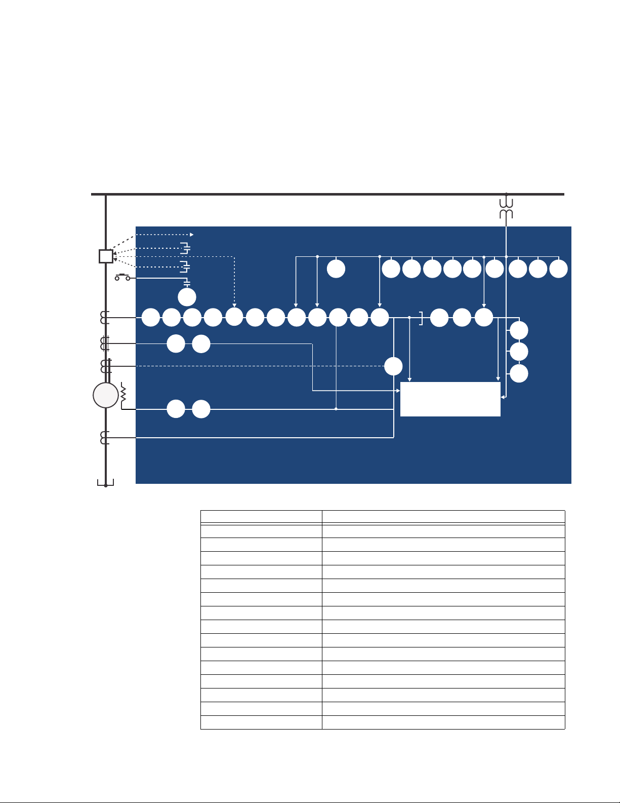
A summary of the available functions and a single-line diagram of protection and control
features is shown below. For a complete understanding of each feature operation, refer to
Chapter 4:
feature and show all logic signals passed between individual features. Information related
to the selection of settings for each setpoint is also provided.
Setpoints. The logic diagrams include a reference to every setpoint related to a
Description of the 869 Motor Protection System
CPU
Relay functions are controlled by two processors: a Freescale MPC5125 32-bit
microprocessor that measures all analog signals and digital inputs and controls all output
relays, and a Freescale MPC8358 32-bit microprocessor that controls all the advanced
Ethernet communication protocols.
Analog Input and Waveform Capture
Magnetic transformers are used to scale-down the incoming analog signals from the
source instrument transformers. The analog signals are then passed through a 11.5 k Hz
low pass analog anti-aliasing filter. All signals are then simultaneously captured by sample
and hold buffers to ensure there are no phase shifts. The signals are converted to digital
values by a 16-bit A/D converter before finally being passed on to the CPU for analysis.
The 'raw' samples are scaled in software, then placed into the waveform capture buffer,
thus emulating a digital fault recorder. The waveforms can be retrieved from the relay via
the EnerVista 8 Series Setup
Frequency
Frequency measurement is accomplished by measuring the time between zero crossings
of the composite signal of three-phase bus voltages, line voltage or three-phase currents.
The signals are passed through a low pass filter to prevent false zero crossings. Frequency
tracking utilizes the measured frequency to set the sampling rate for current and voltage
which results in better accuracy for the Discrete Fourier Transform (DFT) algorithm for offnominal frequencies.
The main frequency tracking source uses three-phase bus voltages. The frequency
tracking is switched automatically by an algorithm to the alternative reference source, i.e.,
three-phase currents signal if the frequency detected from the three-phase voltage inputs
is declared invalid. The switching will not be performed if the frequency from the
alternative reference signal is detected invalid. Upon detecting valid frequency on the
main source, the tracking will be switched back to the main source. If a stable frequency
signal is not available from all sources, then the tracking frequency defaults to the nominal
system frequency.
Phasors, Transients, and Harmonics
All waveforms are processed eight times every cycle through a DC decaying removal filter
and a Discrete Fourier Transform (DFT). The resulting phasors have fault current transients
and all harmonics removed. This results in an overcurrent relay that is extremely secure
and reliable and one that will not overreach.
Processing of AC Current Inputs
The DC Decaying Removal Filter is a short window digital filter, which removes the DC
decaying component from the asymmetrical current present at the moment a fault
occurs. This is done for all current signals used for overcurrent protection; voltage signals
use the same DC Decaying Removal Filter. This filter ensures no overreach of the
overcurrent protection.
The Discrete Fourier Transform (DFT) uses exactly one cycle of samples to calculate a
phasor quantity which represents the signal at the fundamental frequency; all harmonic
components are removed. All subsequent calculations (e.g. power, etc.) are based upon the
software for display and diagnostics.
1–2 869 MOTOR PROTECTION SYSTEM – INSTRUCTION MANUAL
Page 13
CHAPTER 1: INTRODUCTION DESCRIPTION OF THE 869 MOTOR PROTECTION SYSTEM
892825A4.CDR
Phase CT
RTD
27P
59P 59N
59_2
VTFF 81U 81O
87S
METERING
TRANSIENT RECORDER
EVENT RECORDER
FAULT REPORT
TRIP
52
CLOSE
MONITORING
50BF
51P
50P
67P
50_2
50LR
49
BUS
Breaker
32
869
Motor Protection System
Neutral CT
M
50G/N51G/N
67N
86
55
START
3
3
Ground CT
1
Differential
core
balance CT
3
37
47
50G
51G
Internal Summation Percent Differential
Core Balance Percent Differential
81R
40
40Q
78
24
66
38
49S
AFP
27P
LIGHT
current and voltage phasors, such that the resulting values have no harmonic
components. RMS (root mean square) values are calculated from one cycle of samples
prior to filtering.
Protection Elements
All voltage, current and frequency protection elements are processed eight times every
cycle to determine if a pickup has occurred or a timer has expired. The voltage and current
protection elements use RMS current/voltage, or the magnitude of the phasor.
Figure 1-1: Single Line Diagram
Table 1-1: ANSI Device Numbers and Functions
ANSI Device Description
12/14 Over Speed Protection/ Under Speed Protection
24 Volts per Hertz
27P Phase Undervoltage
32 Directional Power
37 Undercurrent
37P Underpower
869 MOTOR PROTECTION SYSTEM – INSTRUCTION MANUAL 1–3
38 Bearing RTD Temperature
40 Loss of Excitation
40Q Reactive Power
46 Current Unbalance
47 Phase Reversal
49 Thermal Model
49S Stator RTD Temperature
50BF Breaker Failure
50G Ground Instantaneous Overcurrent
Page 14

DESCRIPTION OF THE 869 MOTOR PROTECTION SYSTEM CHAPTER 1: INTRODUCTION
ANSI Device Description
50SG Ground Fault
50LR Mechanical Jam
50N Neutral Instantaneous Overcurrent
50P Phase Instantaneous Overcurrent
50_2 Negative Sequence Instantaneous Overcurrent
51G Ground Time Overcurrent
51N Neutral Time Overcurrent
51P Phase Time Overcurrent
52 AC Circuit Breaker
55 Power Factor
59N Neutral Overvoltage
59P Phase Overvoltage
59X Auxiliary Overvoltage
59_2 Negative Sequence Overvoltage
66 Maximum Starting Rate
67N Neutral Directional Element
67P Phase Directional Element
78 Out-of-Step Protection
81O Overfrequency
81U Underfrequency
81R Frequency Rate of Change
86 Start Inhibit
87S Stator Differential
AFP Arc Flash Protection
VTFF Voltage Transformer Fuse Failure
Table 1-2: Other Device Functions
Description
Acceleration Time
Analog Input
Analog Output
Breaker Arcing Current (I2t)
Broken Rotor Bar
Switching Device Control
Breaker Control
Breaker Health
Data Logger
Demand
Digital Counters
Event Recorder
Fault Report
Flexelements
FlexLogic Equations
Flexstates
IEC 61850 Communications
Mechanical Jam
Metering: current, voltage, power, PF, energy, frequency, harmonics, THD
1–4 869 MOTOR PROTECTION SYSTEM – INSTRUCTION MANUAL
Page 15

CHAPTER 1: INTRODUCTION DESCRIPTION OF THE 869 MOTOR PROTECTION SYSTEM
Description
Modbus User Map
Motor Health Report
Motor Learned Data
Motor Start Records
Motor Start Statistics
Non-volatile Latches
OPC-UA Communications
Output Relays
Overload Alarm
Setpoint Groups (6)
Short Circuit
Stator Inter-Turn Fault
Trip Bus (6)
Transient Recorder (Oscillography)
Trip and Close Coil Monitoring
User-programmable LEDs
User-programmable Pushbuttons
Virtual Inputs (32)
Virtual Outputs (32)
Reduced Voltage Starting
RTD Temperature
869 MOTOR PROTECTION SYSTEM – INSTRUCTION MANUAL 1–5
Page 16

DESCRIPTION OF THE 869 MOTOR PROTECTION SYSTEM CHAPTER 1: INTRODUCTION
Setpoints
Device
System
Inputs
Outputs
Protection
Monitoring
Control
FlexLogic
S
tatus
Breakers
Contact Inputs
Output Relays
Virtual Inputs
Virtual Outputs
Targets
Motor
Metering
Records
Events
Transients
Motor Start Records
Breakers
Dig Counters
Clear Records
Currents
Voltages
Frequency
Harmonics
Harmonic Detection
Energy
RTDs
Data Logger
Fault Reports
Motor Start Statistics
Current Demand
Power Demand
Learned Data
Directional Power
Arc Flash
Arc Flash
Testing
PTP Status
Clock
Device Status
Information
Communications
Flex States
Last Trip Data
Summary
Power Factor
Analog Inputs
RTD Maximums
FlexElements
Summary
Switches
Motor
Impedance
Power
Figure 1-2: Main Menu Hierarchy
1–6 869 MOTOR PROTECTION SYSTEM – INSTRUCTION MANUAL
Page 17

CHAPTER 1: INTRODUCTION SECURITY OVERVIEW
Security Overview
The following security features are available:
BASIC SECURITY
The basic security feature is present in the default offering of the 869 relay. The
869 introduces the notion of roles for different levels of authority. Roles are used as login
names with associated passwords stored on the device. The following roles are available
at present: Administrator, Operator, Factory and Observer, with a fixed permission
structure for each one. Note that the Factory role is not available for users, but strictly
used in the manufacturing process.
The 869 can still use the Setpoint access switch feature, but enabling the feature can be
done only by an Administrator. Setpoint access is controlled by a keyed switch to offer
some minimal notion of security.
CYBERSENTRY
The CyberSentry Embedded Security feature is a software option that provides advanced
security services. When the software option is purchased, the Basic Security is
automatically disabled.
CyberSentry provides security through the following features:
• An Authentication, Authorization, Accounting (AAA) Remote Authentication Dial-In
User Service (RADIUS) client that is centrally managed, enables user attribution, and
uses secure standards based strong cryptography for authentication and credential
protection.
• A Role-Based Access Control (RBAC) system that provides a permission model that
device operations and configurations based on specific roles
devices using the Secure Shell (SSH) protocol, the
FASTPATH:
allows access to 869
and individual user accounts configured on the AAA server. At present the defined
roles are: Administrator, Operator and Observer.
• Strong encryption of all access and configuration network messages between the
EnerVista software and 869
Advanced Encryption Standard (AES), and 128-bit keys in Galois Counter Mode (GCM)
as specified in the U.S. National Security Agency Suite B extension for SSH and
approved by the National Institute of Standards and Technology (NIST) FIPS-140-2
standards for cryptographic systems.
• Security event reporting through the Syslog protocol for supporting Security
Information Event Management (SIEM) systems for centralized cyber security
monitoring.
There are two types of authentication supported by CyberSentry that can be used to
access the 869 device:
• Device Authentication – in which case the authentication is performed on the
device itself, using the predefined roles as users (No RADIUS involvement).
869
– 869 authentication using local roles may be done either from the front panel or
through EnerVista.
• Server Authentication - in which case the authentication is done on a RADIUS server,
using individual user accounts defined on the server. When the user accounts are
created, they are assigned to one of the predefined roles recognized by the 869
– 869 authentication using RADIUS server may be done only through EnerVista.
WiFi and USB do not currently support CyberSentry security. For this reason WiFi is
disabled by default if the CyberSentry option is purchased. The user can enable WiFi, but
be aware that doing so violates the security and compliance model that CyberSentry is
supposed to provide.
869 MOTOR PROTECTION SYSTEM – INSTRUCTION MANUAL 1–7
Page 18

869 ORDER CODES CHAPTER 1: INTRODUCTION
NOTE
When both 869 device and server authentication are enabled, the 869 automatically
directs authentication requests to the 869
device or the respective RADIUS server, based
on user names. If the user ID credential does not match one of the device local accounts,
the 869
automatically forwards the request to a RADIUS server when one is provided. If a
RADIUS server is provided, but is unreachable over the network, server authentication
requests are denied. In this situation, use local 869
system.
869
device accounts to gain access to the
USER ROLES
User Access Levels are used to grant varying permissions to specific user roles. User roles
are used by both Basic Security and CyberSentry.
The following user roles are supported:
• Administrator: The Administrator role has complete read and write access to all
settings and commands. The role does not allow concurrent access. The Administrator
role also has an operand to indicate when it is logged on.
• Operator: The Operator role is present to facilitate operational actions that may be
programmed and assigned to buttons on the front panel. The Operator has read/write
access to all settings under the command menu/section. The Operator can view
settings from EnerVista or the front panel but does not have the ability to change any
settings. This role is not a concurrent role.
• Observer: The Observer role has read-only access to all 869 settings. This role allows
concurrent access. The Observer is the default role if no authentication has been done
to the device. This role can download settings files and records from the device.
• Factory: This is an internal non-user accessible role used for manufacturing
diagnostics. The ability to enable or disable this role is a security setting that the
Administrator controls.
GENERAL RULES FOR USER ROLES WITH CYBERSENTRY
1. The only concurrent role is Observer. If the user is logged in through serial, front panel,
or over the network, that counts as the role being logged in for concurrency reasons.
2. Both EnerVista and the front panel provide a one-step logoff. For the front panel, the
root menu has a logoff command. From EnerVista right-clicking on a device and
providing a logoff function from the context menu is sufficient.
3. The EnerVista Login Screen has “User Name:” and “Password:” fields for the default
remote (Radius) authentication, but when a “Local Authentication” checkbox is
selected the “User Name:” field changes to a drop down menu where the user can
select one of the predefined roles on the 869.
869 Order Codes
NOTE:
NOTE:
1–8 869 MOTOR PROTECTION SYSTEM – INSTRUCTION MANUAL
Support of some of the features described in the "Setpoints" section are order code
dependent. Each 8 Series unit is ordered with a number of required and optional modules.
Each of these modules can be supplied in a number of configurations specified at the time
of ordering.
Refer to https://www.gegridsolutions.com/multilin/catalog/869.htm for available order
code combinations.
The information to specify an 869 relay is provided in the following Order Code figure:
Page 19

CHAPTER 1: INTRODUCTION 869 ORDER CODES
869 E ** ** ** H * * A * N G * * * * * * * * * N *
Interface 869 | | | | |||||||||||||||||| 869 Motor Protection System
Application E | | | | | | | | | | | | | | | | | | | | | Standard
Phase Currents ³
Slot J Bank 1/2
P1| ||||||||||||||||||| 1A three-phase current inputs (J1)
P5| ||||||||||||||||||| 5A three-phase current inputs (J1)
Phase Currents ³
Slot K Bank 1
NN | | | | | | | | | | | | | | | | | | | No phase current inputs
P1 | | | | | | | | | | | | | | | | | | | 1A three-phase current inputs (K1)
P5 | | | | | | | | | | | | | | | | | | | 5A three-phase current inputs (K1)
Ground Currents G1 |||||||||||||||||| 1A ground input (J1)
G5|||||||||||||||||| 5A ground input (J1)
B1||||||||||||||||||
1A ground (J1) + 50:0.025A
(K1, included with current protection M option only)
B5||||||||||||||||||
5A ground (J1) + 50:0.025A
(K1, included with current protection M option only)
0B|||||||||||||||||| 50:0.025A (J1), only available if NN is selected for Slot K Bank 1
Power Supply L | | | | | | | | | | | | | | | | | 24 to 48 V DC
H | | | | | | | | | | | | | | | | | 110 to 250 V DC/110 to 230 V AC
Slot B - LV IO N |||||||||||||||| None
R|||||||||||||||| 6 X RTDS (Pt100, Ni100, Ni120)
S|||||||||||||||| 6 X RTDS (Pt100, Ni100, Ni120, Cu10)
Slot C- LV IO N | | | | | | | | | | | | | | | None
R | | | | | | | | | | | | | | | 6 X RTDS (Pt100, Ni100, Ni120)
S | | | | | | | | | | | | | | | 6 X RTDS (Pt100, Ni100, Ni120, Cu10)
Slot F - HV IO A
||||||||||||||||||||||||||||2 Form A (Vmon), 3 Form C, 7 Digital Inputs (Low/High Voltage, Int/Ext
Supply)
Slot G - HV IO N | | | | | | | | | | | | | None
A | | | | | | | | | | | | | 2 Form A, 3 Form C, 7 Digital Inputs (Low/High Voltage, Int/Ext Supply)
L | | | | | | | | | | | | | 7 DcmA O/P + 4 DcmA I/P + 1 RTD
Slot H - HV IO N |||||||||||| None (High Voltage I/O)
F|||||||||||| 10 Digital Inputs + 4 Arc Flash Inputs
A|||||||||||| 2 Form A, 3 Form C, 7 Digital Inputs (Low/High Voltage, Int/Ext Supply)
Faceplate M | | | | | | | | | | | Basic = Membrane Keypad
G | | | | | | | | | | | Standard = Rugged Keypad
Current Protection S | | | |||||||
Basic: 12/14, 19, 37, 38, 46, 49, 50P, 50N, 50G, 50_2, 50LR(Mechanical
Jam), 51P, 51N, 51G, 66, 86
M|||||||||| Standard: Basic + 67P, 67N, 87S (2nd CT Bank required for 87S)
Voltage Monitoring and Protection S | | | | | | | | | Standard: 27P, 27X, 47, 59P, 59N, 59X, 81O, 81U, VTFF
P | | | | | | | | | Advanced : Standard + 32, 40, 40Q, 55, 59_2, 78
Control B | ||||||| Basic: Breaker/Contactor Control, Virtual Inputs
F|||||||| Standard: Basic + FlexLogic, 50BF, Trip Bus
T||||||||
Advanced HMI: Standard + Tab PBs, Annunciator Panel, Configurable
SLDs with Bay Control
Monitoring B
|
|
|
|
|
|
|
|
|
|
|
|
|
|
|
|
|
|
|
|
|
Basic: Motor Health Report, Motor Start Report , Motor Learned Data,
Data Logger, Breakers Coil Monitoring, Breaker Arcing, Harmonics,
THD, Demand
C | | | | | | | Standard: Basic + Breaker Health Report, Broken Rotor Bar
A | | | | | | | Advanced: Standard + Harmonic Detection, Stator Inter-turn Fault
E | | | | | | | Extended: Advanced + ESA Functions
Communications S E
||||||||||Standard: Front USB, 1 x Rear RS485: Modbus RTU, DNP3.0, IEC60870-
5-103 + 1 x Ethernet (Modbus TCP, DNP)
1E
||||||||||Advanced: Front USB, 1 x Rear RS485 + 2 x Ethernet Fiber, MODBUS
RTU/TCP, DNP3.0, IEC 60870-5-103/104, 1588, SNTP, OPC-UA
1P||||| Advanced + PRP
2A||||| Advanced + IEC 61850
2E||||| Advanced + PRP + IEC 61850
3A||||| Advanced + Extended IEC 61850
3E||||| Advanced + PRP + Extended IEC 61850
Advanced Communications Connector N | | | | None
S | | | | ST, Multi-mode 1310 nm
C | | | | RJ45, Copper 10/100M
Figure 1-3: 869 Order Codes
869 MOTOR PROTECTION SYSTEM – INSTRUCTION MANUAL 1–9
Page 20

869 ORDER CODES CHAPTER 1: INTRODUCTION
892800BA.PDF
Wireless Communication N | | | None
W| | | WiFi 802.11
Security B | | Basic
A | | Advanced: CyberSentry Level 1
Future Option N| Not Available
1
Wye 469-869 Retrofit Kit, terminal block wiring assembly for wye (for
retrofit kit only)
2
Delta 469-869 Retrofit Kit, terminal block wiring assembly for delta
(for retrofit kit only)
FASTPATH:
FASTPATH:
Harsh Environment Coating is a standard feature on all 8 Series units.
Advanced security is only available with advanced communications (1E, 1P, 2A, 2E, 3A, 3E).
When the advanced communications option is selected, the Ethernet port on the main CPU
is disabled.
Retrofit order codes must be configured using the GE Multilin Online Store (OLS) based on
the existing relay order code and additional requirements.
Navigate to https://www.gegridsolutions.com/multilin/catalog/869.htm
and click Buy
Retrofit Kit for further information.
Accessories
• 18J0-0030 8 Series Depth Reducing Collar - 1 3/8"
• 18J0-0029 8 Series Depth Reducing Collar - 3"
• 8 Series Retrofit Kit, 469 to 869
1–10 869 MOTOR PROTECTION SYSTEM – INSTRUCTION MANUAL
Page 21

CHAPTER 1: INTRODUCTION SPECIFICATIONS
Specifications
To obtain the total operating time, i.e. from the presence of a trip condition to initiation of a
trip, add 8 ms output relay time to the operate times listed below.
Device
ANNUNCIATOR PANEL
Number of Elements: ........................................1 (36 indicators)
Layout:.....................................................................Grid of 2x2 or 3x3
Data Storage:........................................................Non-volatile memory
Mode:........................................................................Self-reset, latched, acknowledgeable
Display Text:..........................................................3 lines of 15 characters maximum
Visual Indication:.................................................Flashing: 2Hz @ 50% duty cycle
CUSTOM CONFIGURATIONS
Config Mode:.........................................................Simplified, Regular
Protection
ACCELERATION TIME (37P)
Acceleration Current: ........................................1.00 to 10.00 x FLA in steps of 0.01
Operating Mode: .................................................Definite Time, Adaptive
Timing Accuracy:................................................±100 ms or ±0.5% of total time (whichever is greater),
applicable to definite time mode only
ARC FLASH HS PHASE/GROUND INSTANTANEOUS OVERCURRENT HS 50P/50G
Current:....................................................................Phasor Magnitude (special high speed algorithm)
Pickup Level:..........................................................0.050 to 30.000 x CT in steps of 0.001 x CT
Dropout Level: ......................................................97 to 98% of Pickup
Level Accuracy:....................................................For 0.1 to 0.2 x CT: ± 0.2% of reading or 1.5% of rated,
whichever is greater
For > 0.2 x CT: ± 1.5% of reading
Operate Time:.......................................................4 ms at >6 x Pickup at 60 Hz
5 ms at >6 x Pickup at 50 Hz
4-8 ms at > (3-6) x Pickup at 60 Hz
4-10 ms at > (3-6) x Pickup at 50 Hz
AUXILIARY OVERVOLTAGE (59X)
Operating Parameter:.......................................Vx (Phasor)
Pickup Level:..........................................................0.00 to 3.00 x VT in steps of 0.01 x VT
Dropout Level: ......................................................97 to 98% of Pickup
Level Accuracy:....................................................±0.5% of reading from 10 to 240 V
Overvoltage Curves: ..........................................Definite Time, Inverse Time, FlexCurves A/B/C/D
Pickup Time Delay:.............................................0.000 to 6000.000 s in steps of 0.001s
Dropout Time Delay: .........................................0.000 to 6000.000 s in steps of 0.001s
Pickup Accuracy:.................................................‘Auxiliary voltage input channel error
Operate Time:.......................................................< 30 ms at 1.1 x pickup at 60Hz
Curve Timing Accuracy: ..................................at >1.1 x PKP: 3.5% of operate time ± ½ cycle (whichever is
greater) from pickup to operate
Timer Accuracy:..................................................± 3% of operate time or ± ½ cycle (whichever is greater)
869 MOTOR PROTECTION SYSTEM – INSTRUCTION MANUAL 1–11
Page 22

SPECIFICATIONS CHAPTER 1: INTRODUCTION
CURRENT UNBALANCE (46)
Unbalance: ............................................................Unbal = (I2 / I1) x A
A
= (I
A
factor
factor
avg
= 1 if l
/ FLA) if l
avg
Trip/Alarm Pickup Level:..................................4.0 to 50.0% in steps of 0.1%
Trip Operating Curves: .....................................Definite Time: T=TDM sec
Inverse Time: T= (TDM/[Unbal]
Trip Pickup Delay:...............................................0.00 to 180.00 s in steps of 0.01 s when Trip Curve = Definite
Time
Trip Time Dial Multiplier (TDM):.....................0.00 to 180.00 in steps of 0.01 when Trip Curve = Inverse
Curve
Trip Maximum Time: .........................................0.00 to 1000.00 s in steps of 0.01 s
Trip Minimum Time:........................................... 0.00 to 1000.00 s in steps of 0.01 s
Trip Reset Time:................................................... 0.00 to 1000.00 s in steps of 0.01 s
Alarm Time Delay:..............................................0.00 to 180.00 s in steps of 0.01 s
Single Phasing Pickup Level: .........................unbalance level > 40% or when I
in any phase is less than the cutoff current
Single Phasing Time Delay: ...........................2 seconds
Pickup Accuracy: ................................................±2%
Operate Time: ...................................................... <2 cycles at 1.10 x pickup (NOTE 1)
Timing Accuracy:................................................±3% of delay setting time or ± 20 ms, whichever is greater
Element: ..................................................................Trip and Alarm
Single Phasing Element: .................................. Trip
factor
>= FLA
x 100%
< FLA
avg
2
) sec
>=25%FLA and current
avg
DIRECTIONAL POWER (32)
Measured Power:................................................3-phase
Number of Stages: ............................................. 2
Characteristic Angle:......................................... 0º to 359º in steps of 1°
Calibration Angle: ............................................... 0.00º to 0.95º in steps of 0.05°
Power Pickup Range: ........................................ –1.200 to 1.200 x Rated Power in steps of 0.001
Pickup Level Accuracy:.................................... ± 1% or ± 0.001 x Rated Power, whichever is greater
Hysteresis: .............................................................2% or 0.001 x Rated Power, whichever is greater
Pickup Time Delay: ............................................0.000 to 6000.000 s in steps of 0.001 s
Operate Time: ...................................................... < 55 ms at 1.1 x pickup at 60 Hz
< 65 ms at 1.1 x pickup at 50 Hz (NOTE 1)
Timer Accuracy:.................................................. ± 3% of delay setting or ± ¼ cycle (whichever is greater)
from pickup to operate
FLEXELEMENTS
Number of elements:........................................8
Operating signal: ................................................Any analog actual value, or two values in a differential mode
Operating signal mode:...................................Signed, or Absolute value
Operating mode:.................................................Level, Delta
Comparison direction:......................................Over, Under
Pickup Level: .........................................................-30.000 to 30.000 pu in steps of 0.001 pu
Hysteresis: .............................................................0.1 to 50.0% in steps of 0.1%
Delta dt:...................................................................40 msec to 45 days
Pickup and dropout delays:........................... 0.000 to 6000.000 s in steps of 0.001 s
1–12 869 MOTOR PROTECTION SYSTEM – INSTRUCTION MANUAL
Page 23

CHAPTER 1: INTRODUCTION SPECIFICATIONS
FREQUENCY RATE OF CHANGE (81R)
df/dt Trend:............................................................Increasing, Decreasing, Bi-directional
df/dt Pickup Level: ..............................................0.10 to 15.00 Hz/s in steps of 0.01 Hz/s
df/dt Dropout Level:...........................................96% of Pickup Level
df/dt Level Accuracy:........................................80 mHz/s or 3.5%, whichever is greater
Minimum Frequency:........................................20.00 to 80.00 Hz in steps of 0.01 Hz
Maximum Frequency:.......................................20.00 to 80.00 Hz in steps of 0.01 Hz
Minimum Voltage Threshold:.........................0.000 to 1.250 x VT in steps of 0.001 x VT
Minimum Current Threshold:.........................0.000 to 30.000 x CT in steps of 0.001 x CT
Pickup Time Delay:.............................................0.000 to 6000.000 s in steps of 0.001 s
Timer Accuracy:..................................................± 3% of delay setting or ± ¼ cycle (whichever is greater)
from pickup to operate
95% Settling Time for df/dt:...........................< 24 cycles
Operate Time:.......................................................typically 10 cycles at 2 × Pickup
GROUND FAULT (50G)
Pickup Level :.........................................................For 1A/5A Ground CT Type: 0.01 to 10.00 x CT in steps of 0.01
x CT;
For 50/0.025 Ground CT Type: 0.50 to 15.00 A in steps of
0.01A
Dropout Level: ......................................................97 to 98% of Pickup
Alarm Pickup Delay:...........................................0.00 to 180.00 s in steps of 0.01 s
Trip Pickup Start Delay:....................................0.00 to 180.00 s in steps of 0.01 s
Trip Pickup Run Delay:......................................0.00 to 180.00 s in steps of 0.01 s
Magnitude Accuracy:........................................50:0.025A CT: ± 5% of reading or ± 0.2A (in primary)
whichever is greater
1A/5A CT: For 0.1 to 2.0 x CT: ± 0.5% of reading or ± 0.4% of
rated, whichever is greater; For > 2.0 x CT: ± 1.5% of reading
Operate Time:.......................................................<16 ms @ 60Hz (I > 2.0 x PKP), with 0 ms time delay
<20 ms @ 50Hz (I > 2.0 x PKP), with 0 ms time delay
Timing Accuracy:................................................±3% of delay setting at ±1 cycle (whichever is greater) from
pickup to operate
LOSS OF EXCITATION (40)
Operating Condition:.........................................Positive-sequence impedance
Characteristic: ......................................................2 independent negative mho circles (LOE circle 1, 2)
Circle 1(2) Diameter: ..........................................0.1 to 300.0 Ω (in secondary) in steps of 0.1Ω
Circle 1(2) Offset: .................................................0.1 to 300.0 Ω (in secondary) in steps of 0.1Ω
Reach (Impedance) Accuracy:......................± 5%
Under Voltage (UV) Supervision Level: ......0.00 to 1.50 x VT in steps of 0.01 x VT
UV Pickup Accuracy: .........................................as per phase voltage inputs
Pickup Delay: ........................................................0.00 to 600.00 s in steps of 0.01 s
Timer Accuracy:..................................................± 3% of delay setting or ± ½ cycle (whichever is greater)
Operate Time:.......................................................< 3 cycles
MECHANICAL JAM
Operating Condition:.........................................Phase Overcurrent
Arming Condition:...............................................Motor not starting
Pickup Level:..........................................................1.00 to 10.00 x FLA in steps of 0.01
Dropout Level: ......................................................97 to 98% of Pickup
Level Accuracy:....................................................For 0.1 to 2.0 x CT: ±0.5% of reading; at > 2.0 x CT rating:
±1.5% of reading
Pickup Delay: ........................................................0.10 to 180.00 s in steps of 0.01
Dropout Delay:.....................................................0.00 to 180.00 s in steps of 0.01
Timer Accuracy:..................................................±3% of delay setting time or ±20 ms, whichever is greater
869 MOTOR PROTECTION SYSTEM – INSTRUCTION MANUAL 1–13
Page 24

SPECIFICATIONS CHAPTER 1: INTRODUCTION
NEGATIVE SEQUENCE INSTANTANEOUS OVERCURRENT (50_2)
Current:.................................................................... I_2 Fundamental Phasor Magnitude
Pickup Level: .........................................................0.050 to 30.000 x CT in steps of 0.001 x CT
Dropout Level:......................................................97 to 98% of Pickup
Level Accuracy: ...................................................For 0.1 to 2.0 x CT: ±0.5% of reading or ± 0.4% of rated,
whichever is greater
For > 2.0 x CT: ± 1.5% of reading
Pickup Time Delay: ............................................0.000 to 6000.000 s in steps of 0.001 s
Dropout Time Delay:.........................................0.000 to 6000.000 s in steps of 0.001 s
Overreach: .............................................................< 2%
Operate Time: ...................................................... < 12 ms typical at 3 x Pickup at 60 Hz
< 15 ms typical at 3 x Pickup at 50 Hz
Timer Accuracy:..................................................±3% of delay setting or ± ¼ cycle (whichever is greater) from
pickup to operate
NEGATIVE SEQUENCE OVERVOLTAGE (59_2)
Operating Parameter: ......................................V_2
Pickup Level: .........................................................0.00 to 3.00 x VT in steps of 0.01 x VT
Dropout Level:......................................................97 to 98% of Pickup
Level Accuracy: ...................................................± 0.5% of reading from 10 to 208 V
Pickup Time Delay: ............................................0.000 to 6000.000 s in steps of 0.001 s
Dropout Time Delay:.........................................0.000 to 6000.000 s in steps of 0.001 s
Operate Time: ...................................................... < 25 ms at 1.1 x pickup at 60 Hz
< 30 ms at 1.1 x pickup at 50 Hz
Timer Accuracy:.................................................. ± 3% of delay setting or ± ¼ cycle (whichever is greater)
from pickup to operate
NEUTRAL DIRECTIONAL OVERCURRENT (67N)
Directionality: ....................................................... Co-existing forward and reverse
Polarizing:...............................................................Voltage, Current, Dual
Polarizing Voltage:..............................................V_0 or VX
Polarizing Current:.............................................. Ig
Operating Current:.............................................I_0
Level Sensing:.......................................................3 x (|I_0| – K x |I_1|), Ig
Restraint, K:...........................................................0.000 to 0.500 in steps of 0.001
Characteristic Angle:......................................... -90º to 90º in steps of 1°
Limit Angle:............................................................40º to 90º in steps of 1°, independent for forward and
reverse
Angle Accuracy: .................................................. ±2º
Pickup Level: .........................................................0.050 to 30.000 x CT in steps of 0.001 x CT
Dropout Level:......................................................97 to 98% of Pickup
Operate Time (no direction transition): ....< 16 ms at 3 x Pickup at 60 Hz
< 20 ms at 3 x Pickup at 50 Hz
NEUTRAL OVERVOLTAGE (59N)
Operating Parameter: ......................................3V_0 calculated from phase to ground voltages
Pickup Level: .........................................................0.02 to 3.00 x VT in steps of 0.01 x VT
Dropout Level:......................................................97 to 98% of Pickup
Level Accuracy: ...................................................±0.5% of reading from 10 to 208 V
Neutral Overvoltage Curves:.........................Definite time, FlexCurve A,B,C,D
Pickup Time Delay: ............................................0.000 to 6000.000 s in steps of 0.001 s (Definite Time)
Dropout Time Delay:......................................... 0.000 to 6000.000 s in steps of 0.001 s (Definite Time)
Operate Time: ...................................................... < 25 ms at 1.1 x pickup at 60Hz
< 30 ms at 1.1 x pickup at 50Hz
Curve Timing Accuracy:..................................at > 1.1 x Pickup: ± 3% of curve delay or ± 1 cycle (whichever
is greater) from pickup to operate
1–14 869 MOTOR PROTECTION SYSTEM – INSTRUCTION MANUAL
Page 25

CHAPTER 1: INTRODUCTION SPECIFICATIONS
OUT-OF-STEP (78)
Characteristic: ......................................................Single blinder with offset mho supervisory
Measured Impedance:......................................Positive-sequence
Current Supervision Pickup Level:...............0.05 to 10.00 x CT in steps of 0.01 x CT
Fwd/Reverse Reach (sec.): ..............................0.10 to 500.00 Ω in steps of 0.01 Ω
Left and Right Blinders (sec.): ........................0.10 to 500.00 Ω in steps of 0.01 Ω
Impedance Accuracy: ......................................±5%
Blinder RCA: ...........................................................40 to 90º in steps of 1º
Angle Accuracy: ..................................................± 2º
Timer Accuracy:..................................................±3% of operate time or ±¼ cycle (whichever is greater)
OVERFREQUENCY (81O)
Pickup Level:..........................................................20.00 to 65.00 Hz in steps of 0.01
Dropout Level: ......................................................Pickup - 0.03 Hz
Pickup Time Delay:.............................................0.000 to 6000.000 s in steps of 0.001 s
Dropout Time Delay: .........................................0.000 to 6000.000 s in steps of 0.001 s
Minimum Operating Voltage:........................0.000 to 1.250 x VT in steps of 0.001 x VT
Level Accuracy:....................................................± 0.001 Hz
Timer Accuracy:..................................................± 3% of delay setting or ± ¼ cycle (whichever is greater)
from pickup to operate
Operate Time:.......................................................typically 7.5 cycles at 0.1 Hz/s change
typically 7 cycles at 0.3 Hz/s change
typically 6.5 cycles at 0.5 Hz/s change
FASTPATH:
Typical times are average Operate Times including variables such as frequency change
instance, test method, etc., and may vary by ± 0.5 cycles.
OVERLOAD ALARM
Operating Parameter:.......................................Average phase current (RMS)
Pickup Level:..........................................................0.50 to 3.00 x FLA in steps of 0.01 x FLA
Dropout Level: ......................................................97 to 98% of Pickup
Level Accuracy:....................................................For 0.1 to 2.0 x CT: ±0.5% of reading or ±0.4% of rated,
whichever is greater; For > 2.0 × CT rating ±1.5% of reading
Pickup Delay: ........................................................0.00 to 180.00 s in steps of 0.01 s
Dropout Delay:.....................................................0.00 to 180.00 s in steps of 0.01 s
Timer Accuracy: ..................................................±3% of delay setting or ± ½ cycle (whichever is greater) from
pickup to operate
PERCENT DIFFERENTIAL (87S)
Methods: .................................................................Internal summation and Core balance
Pickup Level:..........................................................0.05 to 1.00 x CT in steps of 0.01
Slope 1 and 2:.......................................................1 to 100% in steps of 1
Break 1:....................................................................0.50 to 2.00 x CT in steps of 0.01
Break 2:....................................................................2.00 to 30.00 x CT in steps of 0.01
Operate Time:.......................................................<16 ms at >3 × Pickup at 60 Hz;
<20 ms at >3 × Pickup at 50 Hz
PHASE DIRECTIONAL OVERCURRENT (67P)
Relay Connection: ..............................................90º(Quadrature)
Quadrature Voltage:..........................................ABC phase seq.: phase A (Vbc), phase B (Vca), phase C (Vab);
ACB phase seq.: phase A (Vcb), phase B (Vac), phase C (Vba)
Polarizing Voltage Threshold:........................0.050 to 3.000 x VT in steps of 0.001 x VT
Current Sensitivity Threshold:.......................0.05 x CT
Characteristic Angle:.........................................0º to 359º in steps of 1°
Angle Accuracy: ..................................................± 2º
Operation Time (FlexLogic™ operands):..Reverse to Forward transition: < 12 ms, typically;
Forward to Reverse transition: <8 ms, typically
869 MOTOR PROTECTION SYSTEM – INSTRUCTION MANUAL 1–15
Page 26

SPECIFICATIONS CHAPTER 1: INTRODUCTION
NOTE
PHASE/NEUTRAL/GROUND TIME OVERCURRENT (51P/N/G)
Current:.................................................................... Phasor or RMS
Pickup Level: .........................................................0.050 to 30.000 x CT in steps of 0.001 x CT
Dropout Level:......................................................97 to 98% of Pickup
Level Accuracy: ...................................................For 0.1 to 2.0 x CT: ±0.5% of reading or ±0.4% of rated,
whichever is greater;
For > 2.0 x CT: ±1.5% of reading
Curve Shape:......................................................... IEEE Extremely/Very/Moderately Inverse;
ANSI Extremely/Very/Normally/Moderately Inverse;
Definite T ime, IEC A/B/C and Short Inverse;
IAC Extremely/Very/Inverse/Short Inverse;
FlexCurve A/B/C/D, I
2
t, I4t
Curve Multiplier: ..................................................0.05 to 600.00 in steps of 0.01
Reset Time: ............................................................Instantaneous, Timed
Curve Timing Accuracy:..................................Currents > 1.03 to 20 x pickup: ± 3% of operate time or ± ½
cycle (whichever is greater) from pickup to operate
Voltage Restrained Function (51V): ............ Modifies Pickup from 0.1 < V < 0.9 VT Nominal in a fixed
linear relationship
FASTPATH:
Add 1.5 cycles to the curve time to obtain the TOC operating time, i.e., from fault inception
until operation.
PHASE/NEUTRAL/GROUND INSTANTANEOUS OVERCURRENT (50P/N/G)
Current (for Phase IOC only):.........................Phasor or RMS
Current (for Neutral/Ground IOC only):.....Fundamental Phasor Magnitude
Pickup Level: .........................................................0.050 to 30.000 x CT in steps of 0.001 x CT
Dropout Level:......................................................97 to 98% of Pickup
Level Accuracy: ...................................................For 0.1 to 2.0 x CT: ±0.5% of reading or ±0.4% of rated,
whichever is greater
For > 2.0 x CT: ±1.5% of reading
Operate Time: ...................................................... <12 ms typical at 3 × Pickup at 60 Hz (Phase/Ground IOC)
<16 ms typical at 3 × Pickup at 60 Hz (Neutral IOC)
<15 ms typical at 3 × Pickup at 50 Hz (Phase/Ground IOC)
<20 ms typical at 3 × Pickup at 50 Hz (Neutral IOC)
NOTE:
Operating time specifications given above are applicable when RMS inputs are used.
Typical times are average operate times over multiple test cases.
Timer Accuracy:..................................................±3% of delay setting or ± ¼ cycle (whichever is greater) from
pickup to operate
PHASE REVERSAL
Phase Reversal Condition:..............................V2/V1=100% when phase to phase voltages are greater than
50% of VT
Configuration: ......................................................ABC or ACB phase rotation
Pickup/Dropout Time Delay: .........................0.00 to 180.00 s in steps of 0.01 s
Timer Accuracy:.................................................. ±3% of delay setting or ±1% cycle (whichever is greater)
from pickup to operate
1–16 869 MOTOR PROTECTION SYSTEM – INSTRUCTION MANUAL
Page 27

CHAPTER 1: INTRODUCTION SPECIFICATIONS
PHASE UNDERVOLTAGE (27P)
Voltage:....................................................................Fundamental Phasor Magnitude
Minimum Voltage:...............................................0.00 to 1.50 x VT in steps of 0.01 x VT
Pickup Level:..........................................................0.00 to 1.50 x VT in steps of 0.01 x VT
Dropout Level: ......................................................102 to 103% of Pickup
Level Accuracy:....................................................±0.5% of reading from 10 to 208 V
Phases Required for Operation:...................Any one, Any two, All three
Undervoltage Curves: .......................................Definite Time, GE IAV Inverse Time or FlexCurves A/B/C/D
Pickup Time Delay:.............................................0.000 to 6000.000 s in steps of 0.001s
Operate Time:.......................................................< 20 ms at 0.90 x pickup at 60 Hz
< 25 ms at 0.90 x pickup at 50 Hz
Curve Timing Accuracy: ..................................at < 0.90 x pickup: ± 3.5% of curve delay or ± ½ cycle
(whichever is greater) from pickup to operate
PHASE OVERVOLTAGE (59P)
Voltage:....................................................................Fundamental Phasor Magnitude
Pickup Level:..........................................................0.02 to 3.00 x VT in steps of 0.01 x VT
Dropout Level: ......................................................97 to 98% of Pickup
Level Accuracy:....................................................±0.5% of reading from 10 to 208 V
Phases Required for Operation:...................Any one, Any two, All three
Pickup Time Delay:.............................................0.000 to 6000.000 s in steps of 0.001s (Definite Time)
Dropout Time Delay: .........................................0.000 to 6000.000 s in steps of 0.001s (Definite Time)
Pickup Accuracy:.................................................Per phase voltage input channel error
Operate Time:.......................................................< 25 ms at 1.1 x pickup at 60Hz
< 30 ms at 1.1 x pickup at 50Hz
Timer Accuracy:..................................................± 3% of delay setting or ± ¼ cycle (whichever is greater)
from pickup to operate
REACTIVE POWER (40Q)
Operating Condition:.........................................Three-phase reactive power
Positive/Negative var Trip/Alarm Pickup
Level:....................................................................0.02 to 2.00 x Rated in steps of 0.01
Positive/Negative var Trip/Alarm Pickup
Level:....................................................................1 to 25000 kvar in steps of 1 kvar
Pickup Level Accuracy: ....................................±1.0% of reading
Positive/Negative var Trip/Alarm Pickup
Delay:..................................................................0.00 to 600.00 s in steps of 0.01 s
Timer Accuracy:..................................................±3.0% of delay time or ±10 ms, whichever is greater
Hysteresis:..............................................................2 to 3%
Operate Time:.......................................................< 45 ms at 60 Hz
< 50 ms at 50 Hz
Elements: ................................................................Trip and Alarm
RTD PROTECTION
Pickup:......................................................................1°C to 250°C in steps of 1°C
Hysteresis:..............................................................2°C
Timer Accuracy:..................................................<2 s
Elements: ................................................................Trip and Alarm
869 MOTOR PROTECTION SYSTEM – INSTRUCTION MANUAL 1–17
Page 28
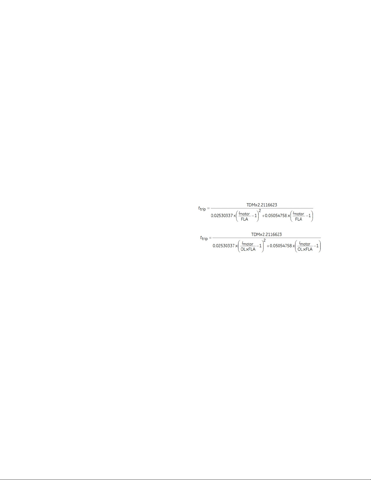
SPECIFICATIONS CHAPTER 1: INTRODUCTION
SHORT CIRCUIT
Inputs: ......................................................................RMS Phase Currents
Pickup Level: .........................................................1.00 to 30.00 x CT in steps of 0.01 x CT
Dropout Level:......................................................97 to 98% of Pickup
Pickup Delay:........................................................0.00 to 180.00 s in steps of 0.01 s
Level Accuracy: ...................................................For 1.0 to 2.0 x CT: ±0.5% of reading or ±0.4% of rated,
whichever is greater For > 2.0 x CT: ±1.5% of reading
Operate Time: ...................................................... <16 ms @ 60Hz (I > 2.0 x PKP), with 0 ms time delay
<20 ms @ 50Hz (I > 2.0 x PKP), with 0 ms time delay
Timer Accuracy:.................................................. ±3% of delay setting or ±1/2 cycle (whichever is greater)
from pickup to operate
Elements:................................................................Trip or Alarm
THERMAL MODEL (49)
Thermal Overload Curves:..............................Motor curve, FlexCurve, Standard Motor curve with voltage
dependent function, FlexCurve with voltage dependent
function, IEC curve
Motor Curve Time Multiplier:......................... 0.00 to 25.00 in steps of 0.01
FlexCurve Time Multiplier:..............................0.00 to 600.00 in steps of 0.01
IEC Curve Time Constant:...............................0 to 1000 in steps of 1
Thermal Overload Pickup: ..............................Overload factor x FLA
Overload Factor (OL): ........................................1.00 to 1.50 in steps of 0.01
Motor Full Load Current (FLA): ......................1 to 5000 A in steps of 1
Standard Overload Curve, Cutoff
Effect:.................................................................
Standard Overload Curve, Shift
Effect:.................................................................
Motor Rated Voltage:........................................1 to 50000 V in steps of 1
Thermal Model Biasing: ...................................Current Unbalance, RTDs
Thermal Model Update Rate: ........................ 1 power cycle
Stopped/Running Cool Time Constants:.. 1 to 1000 min. in steps of 1
Stopped/Running Cool Time Constant
Decay: ................................................................Exponential
Hot/Cold Safe Stall Ratio:................................ 0.01 to 1.00 in steps of 0.01
Current Accuracy: .............................................. Per phase current inputs
Current Source:.................................................... True RMS
Timer Accuracy:.................................................. ±100 ms or ±2%, whichever is greater
Timer Accuracy for Voltage Dependent
Overload:...........................................................±100 ms or ±4%, whichever is greater
UNDERCURRENT (37)
Operating Parameter: ......................................Per-phase current Ia, Ib, Ic (Phasor)
Trip/Alarm Pickup Level:..................................0.10 to 0.95 x FLA in steps of 0.01 x FLA
Dropout Level:......................................................102 to 103% of Pickup
Trip/Alarm Time Delay: .................................... 0.00 to 180.00 s in steps of 0.01 s
Pickup Accuracy: ................................................For 0.1 to 2.0 x CT: ±0.5% of reading or ±0.4% of rated,
whichever is greater
Operate Time: ...................................................... <45 ms at 60 Hz,<50 ms at 50 Hz
Timer Accuracy:.................................................. ±3% of delay setting or ± 2 power cycles (whichever is
greater) from pickup to operate
Stages:..................................................................... Trip and Alarm
1–18 869 MOTOR PROTECTION SYSTEM – INSTRUCTION MANUAL
Page 29

CHAPTER 1: INTRODUCTION SPECIFICATIONS
UNDERFREQUENCY (81U)
Pickup Level:..........................................................20.00 to 65.00 Hz in steps of 0.01
Dropout Level: ......................................................Pickup + 0.03 Hz
Pickup Time Delay:.............................................0.000 to 6000.000 s in steps of 0.001s
Dropout Time Delay: .........................................0.000 to 6000.000 s in steps of 0.001s
Minimum Operating Voltage:........................0.000 to 1.250 x VT in steps of 0.001 x VT
Minimum Operating Current: ........................0.000 to 30.000 x CT in steps of 0.001 x CT
Level Accuracy:....................................................± 0.001 Hz
Timer Accuracy:..................................................± 3% of delay setting or ± ¼ cycle (whichever is greater)
from pickup to operate
Operate Time:.......................................................typically 7.5 cycles at 0.1 Hz/s change
typically 7 cycles at 0.3 Hz/s change
typically 6.5 cycles at 0.5 Hz/s change
FASTPATH:
Typical times are average Operate Times including variables such as frequency change
instance, test method, etc., and may vary by ± 0.5 cycles.
UNDERPOWER
Operating Condition:.........................................Three-phase real power
Number of Elements: ........................................1, alarm and trip stages
Trip/Alarm Pickup Level: ..................................1 to 25000 kW in steps of 1
Pickup Level Accuracy: ....................................±1.0% of reading
Hysteresis:..............................................................3%
Trip/Alarm Pickup Delay:.................................0 to 180.00 s in steps of 0.01
Timer Accuracy: ..................................................±3% of delay time or ±10 ms, whichever is greater, pick up to
operate
Operate Time:.......................................................<45 ms at 60 Hz; <50 ms at 50 Hz (NOTE 1)
VOLTS PER HERTZ (24)
Voltages:..................................................................Phasor only
Pickup Level:..........................................................0.80 to 4.00 in steps of 0.01 pu
Dropout Level: ......................................................97 to 98% of pickup
Level Accuracy:....................................................±0.02 pu
Timing Curves: .....................................................Definite T ime; IEC Inverse A/B/C; FlexCurves A, B, C, and D
TD Multiplier: .........................................................0.05 to 600.00 s in steps of 0.01
Reset Delay:...........................................................0.00 to 6000.000 s in steps of 0.01
Timer Accuracy:..................................................±3% of operate time or ±15 cycles (whichever is greater) for
values greater than 1.1 x pickup
Number of Elements: ........................................2
Number of Elements: ........................................1
(NOTE 1) When the setpoint “Motor Load Filter Interval” is programmed as non-zero, it
might increase the trip/alarm times by 16.7 ms (or 20 ms at 50 Hz) for each additional
cycle in the filter interval for the following protection elements: Acceleration Time, Current
Unbalance, Mechanical Jam, Overload Alarm, Thermal Model, Undercurent, Power Factor,
and Underpower.
869 MOTOR PROTECTION SYSTEM – INSTRUCTION MANUAL 1–19
Page 30

SPECIFICATIONS CHAPTER 1: INTRODUCTION
Control
ARC FLASH SENSOR/FIBER
Number of Point Sensors:...............................4
Detection Radius: ...............................................180 degree
Maximum Fiber Length (Point Sensor):..... 18 ft
Fiber Size: ...............................................................1000 um
Mode:........................................................................ Multi-mode
Connector: .............................................................Small Media Interface (SMI)
Fiber Type: .............................................................Plastic Optical Fiber
Bend Radius:.........................................................>25 mm
BREAKER CONTROL
Operation: ..............................................................Asserted FlexLogic Operands
Function:.................................................................Opens/closes, blocks, bypasses blocks to the feeder breaker
BREAKER FAILURE
Mode:........................................................................ 3-pole
Current Supervision:.......................................... phase and neutral current (fundamental phasor magnitude)
Current Supervision Pickup:........................... 0.050 to 30.000 x CT in steps of 0.001 x CT
Current Supervision Dropout: ....................... 97 to 98% of pickup
Current Supervision Accuracy: ....................For 0.1 to 2.0 x CT: ± 0.5% of reading or ± 0.4% of rated
(whichever is greater),
For > 2.0 x CT: ± 1.5% of reading
Time Delay: ........................................................... 0.000 to 6000.000 s in steps of 0.001 s
Timer Accuracy:.................................................. ± 3% of delay setting or ± ¼ cycle (whichever is greater)
from pickup to operate
Reset Time: ............................................................< 10 ms typical at 2 x Pickup at 60 Hz
< 12 ms typical at 2 x Pickup at 50 Hz
LOCAL CONTROL MODE
Number of Elements: ........................................ 1
Select Before Operate Mode: ........................Disabled, Enabled
Mode:........................................................................ Local Mode ON, Local Mode OFF
Display Status:.....................................................LM (local mode) displayed in banner
Tagging: ..................................................................Disabled, Enabled
MAXIMUM STARTING RATE
Monitored Time Interval:................................. 1 to 300 minutes in steps of 1
Maximum Number of Starts:......................... 1 to 16 starts in steps of 1
Timer Accuracy:.................................................. ±2s or ±1% of total time (whichever is greater)
RESTART DELAY
Restart Delay:....................................................... 0 to 65000 seconds in steps of 1
Timer Accuracy:.................................................. ±2s or ±1% of total time (whichever is greater)
REDUCED VOLTAGE START
Mode:........................................................................ Current Only, Current and Timer, Current or Timer
Start Current Level:............................................0.25 to 3.00 of FLA, in steps of 0.01
Start Timer: ............................................................ 1.0 to 600.0 s in steps of 0.1
SWITCH CONTROL
Operation: ..............................................................Local (PB control and SLD) and Remote (asserted FlexLogic
operands)
Function:.................................................................Opens/Closes the disconnect switch
Timers:.....................................................................0.000 to 6000.000 s in steps of 0.001 s
TIME BETWEEN STARTS
Time Between Starts:........................................0 to 300 minutes in steps of 1
Timer Accuracy:.................................................. ±2s or ±1% of total time (whichever is greater)
1–20 869 MOTOR PROTECTION SYSTEM – INSTRUCTION MANUAL
Page 31

CHAPTER 1: INTRODUCTION SPECIFICATIONS
TRIP BUS
Number of Elements: ........................................6
Number of Inputs:...............................................16
Pickup Time Delay:.............................................0.000 to 6000.000 s in steps of 0.001 s
Dropout Time Delay: .........................................0.000 to 6000.000 s in steps of 0.001 s
Operate Time:.......................................................< 2 ms at 60 Hz
Timer Accuracy:..................................................± 3% of delay time or ± ¼ cycle (whichever is greater) from
pickup to operate
Monitoring
BREAKER ARCING CURRENT
Mode:........................................................................3-pole
Principle:..................................................................accumulates breaker duty (I
Initiation: .................................................................any operand
Alarm Threshold:.................................................0 to 50000 kA2-cycle in steps of 1 kA2-cycle
Timer Accuracy:..................................................± 3% of delay setting or ± ¼ cycle (whichever is greater)
from pickup to operate
BREAKER FAILURE
Mode:........................................................................3-pole
Current Supervision:..........................................phase and neutral current (fundamental phasor magnitude)
Current Supervision Pickup:...........................0.050 to 30.000 x CT in steps of 0.001 x CT
Current Supervision Dropout: .......................97 to 98% of pickup
Current Supervision Accuracy:.....................For 0.1 to 2.0 x CT: ± 0.5% of reading or ± 0.4% of rated
(whichever is greater),
For > 2.0 x CT: ± 1.5% of reading
Time Delay:............................................................0.000 to 6000.000 s in steps of 0.001 s
Timer Accuracy:..................................................± 3% of delay setting or ± ¼ cycle (whichever is greater)
from pickup to operate
Reset Time: ............................................................< 10 ms typical at 2 x Pickup at 60 Hz
< 12 ms typical at 2 x Pickup at 50 Hz
BREAKER HEALTH
Timer Accuracy:..................................................± 3% of delay setting or ± 1 cycle (whichever is greater) from
pickup to operate
BROKEN ROTOR BAR
Operating Parameter:.......................................Fundamental Phasor Magnitude
Pickup Level:..........................................................-60db to -12db in steps of -1dB
Dropout Level: ......................................................97 to 98% of Pickup
CLOSE CIRCUIT MONITOR (CCM)
Applicable Voltage: ............................................20 to 250 VDC
Trickle Current:.....................................................1 to 2.5 mA
Timing Accuracy:................................................± 3 % or ± 4 ms, whichever is greater
DEMAND
Measured Values:................................................Phase A/B/C present and maximum current
Measurement Type:...........................................Thermal Exponential, 90% response time (programmed): 5,
10, 15, 20, 30 minutes
Block Interval / Rolling Demand, time interval (programmed):
5, 10, 15, 20, 30 minutes
Current Pickup Level:.........................................10 to 10000 in steps of 1 A
Dropout Level: ......................................................96-98% of Pickup level
Level Accuracy:....................................................± 2%
2
t) during fault
869 MOTOR PROTECTION SYSTEM – INSTRUCTION MANUAL 1–21
Page 32

SPECIFICATIONS CHAPTER 1: INTRODUCTION
ESA (ELECTRICAL SIGNATURE ANALYSIS)
ESA (Bearing & Mechanical (Foundation looseness, Eccentricity and Mis-alignment)) Fault
Computing Parameter: ....................................Ia or Ib or Ic
Indicating Parameter:....................................... Peak Magnitude (dB), Energy (dB), Change in dB
Operating Parameter: ......................................Change in Peak and Energy magnitude (dB) or Peak and
Energy magnitude (dB)
Pickup level 1 & 2:............................................... Change in Peak and Energy magnitude > ‘X’ dB w.r.t base line
dB (configurable in setup SW) or Peak and Energy magnitude
> ‘X’ dB w.r.t base line dB (configurable in setup SW)
Pickup delay 1 & 2: ............................................5 to 60 min (multiples of 5 min) (Configurable in setup
software)
FAULT REPORTS
Number of Reports: ...........................................15
Captured Data: .................................................... Pre-fault and fault phasors for all CT and VT banks, pre-fault
and fault trigger operands, user-programmable analog
channels 1 to 32
HARMONIC DETECTION
Operating Parameter: ......................................Current 2nd, 3rd, 4th, 5th harmonic or THD per phase
Timer Accuracy:.................................................. Harmonics: ±3% of delay setting or ±1/4 cycle (whichever is
greater) from pickup to operate
THD: ±3% of delay setting or ±3 cycles (whichever is greater)
from pickup to operate
POWER FACTOR (55)
Switch-In Level:.................................................... 0.01 Lead to 1 to 0.01 Lag in steps of 0.01
Dropout Level:......................................................0.01 Lead to 1 to 0.01 Lag in steps of 0.01
Delay: ....................................................................... 0.000 to 6000.000 s in steps of 0.001 s
Minimum Operating Voltage:........................ 0.00 to 1.25 x VT in steps of 0.01 x VT
Level Accuracy: ...................................................± 0.02
Timer Accuracy:.................................................. ± 3% of delay setting or ± 1¼ cycle (whichever is greater)
from pickup to operate
SPEED PROTECTION
Configuration: ......................................................Assign to any contact input
Operating Range: ...............................................50 to 120% of Rated RPM
Minimum Pulse Width: .....................................>8% of a revolution
Level Accuracy: ...................................................±1% of rated speed
Timer Accuracy:.................................................. ±3% of delay setting or ±2 power cycles (whichever is
greater) from pickup to operate
Element: ..................................................................Trip and Alarm
STATOR TURN FAULT
Operating Parameter: ......................................I_2, V_1, V_2
Pickup Level Stage1/Stage2:.........................0.001 to 10.000 in steps of 0.001
Level Accuracy: ...................................................For 1.0 to 2.0 x CT: ±0.5% of reading or ±0.4% of rated,
whichever is greater For > 2.0 x CT: ±1.5% of reading
Dropout Level:......................................................97 to 98% of Pickup
Pickup Delay Stage1/Stage2:........................ 0.01 to 600.00 in steps of 0.01
Operate Time: ...................................................... <16 ms at 3 x pickup at 60 Hz
Timer Accuracy:.................................................. ±3% of operate time or ± 1/4 cycle (whichever is greater)
TRIP CIRCUIT MONITOR (TCM)
Applicable Voltage:............................................20 to 250 VDC
Trickle Current:..................................................... 1 to 2.5 mA
Timing Accuracy:................................................± 3 % or ± 4 ms, whichever is greater
1–22 869 MOTOR PROTECTION SYSTEM – INSTRUCTION MANUAL
Page 33

CHAPTER 1: INTRODUCTION SPECIFICATIONS
Recording
EVENT DATA
Number of Records:...........................................1024 (matches the existing Event Recorder)
Data Storage:........................................................Non-volatile memory
Time-tag Accuracy: ...........................................One microsecond
Settings:...................................................................64 Configurable FlexAnalog parameters,
Event Selector
Actuals:....................................................................Selected Event Number,
Timestamp of Selected Event ,
Cause of Selected Event,
64 Configurable FlexAnalog values
Commands: ...........................................................None (using existing Clear Event Recorder)
MOTOR START STATISTICS
Number of records:............................................5
Content:...................................................................Start Date/Time, Start Acceleration Time, Start Effective
Current, Start Peak Current
Number of records:............................................Non-volatile memory
MOTOR START RECORDS
Length:.....................................................................6 records, each containing a total of 60 seconds of motor
starting data
Trigger:.....................................................................Motor starting status
Trigger Position:...................................................1 second pre-trigger duration
Sample Rate:.........................................................1 sample/200 ms
MOTOR LEARNED DATA
Number of records:............................................250
Content:...................................................................Learned/last acceleration time, learned/last starting current,
learned/last start TCU, learned average load, learned
average real power, learned average reactive power, learned
average power factor, average run time (days/hours/
minutes), maximum speed, analog input minimum/
maximum values, RTD maximum temperature
Data Storage:........................................................ .LDR File, CSV Format
Learned acceleration time accuracy:.......3%
Learned starting current accuracy:...........1%
Learned average motor load accuracy:..1%
Learned average power accuracy:............1%
TRANSIENT RECORDER
Default AC Channels:.........................................8 currents + 4 voltages
Configurable Channels: ...................................16 analog and 64 digital channels
Sampling Rate:.....................................................128/c, 64/c, 32/c, 16/c, 8/c
Trigger Source:.....................................................Any element pickup, dropout or operate, digital input or
output change of state, FlexLogic operand
Trigger Position:...................................................0 to 100%
Storage Capability: ............................................Non-volatile memory
DATA LOGGER
Data Logger channels:.....................................16
Data Logger Rate:...............................................1 cycle, 1 sec., 30 sec., 1 min., 15 min., 30 min., 1 hour
Inputs:.......................................................................Any analog parameter from the list of available analog
parameters
Data Collection Mode:.......................................Continuous, Triggered
Trigger Source:.....................................................Any digital flag from the list of digital flags
Trigger Position:...................................................0 to 50% in steps of 1%
Channel 1(16) Mode:..........................................Sample, Min, Max, Mean
869 MOTOR PROTECTION SYSTEM – INSTRUCTION MANUAL 1–23
Page 34

SPECIFICATIONS CHAPTER 1: INTRODUCTION
EVENT RECORDER
Number of events:.............................................. 1024
Header:....................................................................relay name, order code, firmware revision
Content:................................................................... any element pickup, any element operate, digital input
change of state, digital output change of state, self-test
events
Data Storage:........................................................non-volatile memory
Time-tag Accuracy:........................................... to one microsecond
LAST TRIP DATA
Number of Records: ..........................................1
Data Storage:........................................................Non-volatile memory
Time-tag Accuracy:........................................... One microsecond
Actuals:....................................................................Event Number of Last Trip,
Timestamp of Last Trip,
Cause of Last Trip,
64 Configurable FlexAnalog values
Commands:...........................................................Clear Last Trip Data
User-Programmable Elements
FLEXLOGIC
Lines of code:........................................................ 1024
Supported operations: .....................................NOT, XOR, OR (2 to 16 inputs), AND (2 to 16 inputs), NOR (2 to
16 inputs), NAND (2 to 16 inputs), latch (reset-dominant),
edge detectors, timers
Inputs: ......................................................................any logical variable, contact, or virtual input
Number of timers: .............................................. 32
Pickup delay: ........................................................0 to 60000 (ms, sec., min.) in steps of 1
Dropout delay:.....................................................0 to 60000 (ms, sec., min.) in steps of 1
Timer accuracy:.................................................. ±3% of delay setting or ±¼ cycle (whichever is greater) from
pickup to operate
FLEXELEMENTS
Number of elements:........................................8
Operating signal: ................................................Any analog actual value, or two values in a differential mode
Operating signal mode:...................................Signed, or Absolute value
Operating mode:.................................................Level, Delta
Comparison direction:......................................Over, Under
Pickup Level: .........................................................-30.000 to 30.000 pu in steps of 0.001 pu
Hysteresis: .............................................................0.1 to 50.0% in steps of 0.1%
Delta dt:...................................................................40 msec to 45 days
Pickup and dropout delays:........................... 0.000 to 6000.000 s in steps of 0.001 s
FLEXSTATES
Number of States: ..............................................256 logical variables grouped under 16 Modbus addresses
Programmability:................................................ Any FlexLogic operand, any digital input, any virtual input,
any remote input
NON-VOLATILE LATCHES
Type:......................................................................... Set-dominant or Reset-dominant
Range:......................................................................16 individually programmed
Output:..................................................................... Stored in non-volatile memory
Execution sequence:.........................................As input prior to protection, control and FlexLogic
FLEXCURVES
Number: .................................................................. 4 (A through D)
Reset points:.......................................................... 40 (0.00 to 0.98 x pickup)
Operate points:....................................................80 (1.03 to 20.0 x pickup)
Time delay:............................................................ 0 to 200,000,000 ms in steps of 1 ms
Saturation level: ..................................................20 times the pickup level
1–24 869 MOTOR PROTECTION SYSTEM – INSTRUCTION MANUAL
Page 35

CHAPTER 1: INTRODUCTION SPECIFICATIONS
TAB PUSHBUTTONS
Number of elements: ........................................1 (20 Tab Pushbuttons)
Data Storage:........................................................Non-volatile memory
Mode:........................................................................Self-reset, latched
Display Message:................................................2 lines; 15 characters per line
Dropout Timer: .....................................................0.000 to 60.000 s in steps of 0.005
Auto-reset Timer: ................................................0.2 to 600.0 s in steps of 0.1
Hold Timer: ............................................................0.1 to 10.0 s in steps of 0.1
Timer Accuracy:..................................................±3% of delay setting or ±¼ cycle (whichever is greater) from
pickup to operate
USER-PROGRAMMABLE LEDS
Number: ..................................................................17 (14 + 3 PB LEDS) for Membrane and Rugged Front Panels
Programmability:................................................any logic variable, contact, or virtual input
Reset mode:........................................................... self-reset or latched
USER-PROGRAMMABLE PUSHBUTTONS
Number of pushbuttons:.................................3 (Membrane and Rugged Front Panels)
Mode:........................................................................Self-reset, latched
Display message:................................................2 lines of 13 characters on each line
Dropout timer:......................................................0.000 to 60.000 s in steps of 0.005
Auto-reset timer:.................................................0.2 to 600.0 s in steps of 0.1
Hold timer:..............................................................0.0 to 10.0 s in steps of 0.1
Metering
MOTOR
Motor Metered Values
Parameters: ...........................................................Motor Load, Thermal Model Biased Load, Filtered Motor
Load, Filtered RMS Phase A, B, C Currents, Filtered Phasor
Magnitude Phase A, B, C Currents
RMS Accuracy: .....................................................± 0.25% of reading or ± 0.2% of rated (whichever is greater)
from 0.1 to 2.0 x CT
± 1% of reading > 2.0 x CT
Magnitude Accuracy:........................................± 0.5% of reading or ± 0.2% of rated (whichever is greater)
from 0.1 to 2.0 x CT
RMS PARAMETERS
Currents
Parameters: ...........................................................Phase A, B, C, Neutral, Ground
Accuracy:................................................................± 0.25% of reading or ± 0.2% of rated (whichever is greater)
from 0.1 to 2.0 x CT
± 1% of reading > 2.0 x CT
Voltages
Parameters: ...........................................................Wye VTs: A-n, B-n, C-n, A-B, B-C, C-A, Average Phase, Neutral
and Residual
Delta VTs: A-B, B-C, C-A, Neutral and Residual
Accuracy:................................................................± 0.5% of reading from 15 to 208 V
± 1% for open Delta connections
Real Power (Watts)
Range: ......................................................................-214748364.8 kW to 214748364.7 kW
Parameters: ...........................................................3-phase; per phase if VT is Wye
Accuracy:................................................................± 1.0% of reading or 0.2 kW (whichever is greater) at -0.8 <
PF ≤ -1.0 and 0.8 < PF < 1.0
Reactive Power (Vars)
Range: ......................................................................-214748364.8 kvar to 214748364.7 kvar
Parameters: ...........................................................3-phase; per phase if VT is Wye
Accuracy:................................................................± 1.0% of reading or 0.2 kvar (whichever is greater) at -0.2 <
PF ≤ 0.2
869 MOTOR PROTECTION SYSTEM – INSTRUCTION MANUAL 1–25
Page 36

SPECIFICATIONS CHAPTER 1: INTRODUCTION
Apparent Power (VA)
Range:......................................................................0 kVA to 214748364.7 kVA
Parameters:...........................................................3-phase; per phase if VT is Wye
Accuracy: ...............................................................± 1.0% of reading or 0.2 kVA (whichever is greater)
Power Factor
Parameters:...........................................................3-phase; per phase if VT is Wye
Range:......................................................................0.01 Lag to 1.00 to 0.01 Lead
Accuracy: ...............................................................± 0.02 for 50 Hz and 60 Hz; ± 0.05 for 25 Hz
Watt-hours (positive and negative)
Range:......................................................................- 2147483.648 MWh to 2147483.647 MWh
Parameters:...........................................................3-phase only
Update Rate:.........................................................50 ms
Accuracy: ...............................................................± 2.0% of reading
Var-hours (positive and negative)
Range:......................................................................- 2147483.648 Mvarh to 2147483.647 Mvarh
Parameters:...........................................................3-phase only
Update Rate:.........................................................50 ms
Accuracy: ...............................................................± 2.0% of reading
PHASORS
Current
Parameters:...........................................................Phase A, B, C, Neutral and Ground
Magnitude Accuracy: .......................................± 0.5% of reading or ± 0.2% of rated (whichever is greater)
from 0.1 to 2.0 x CT
± 1.0% of reading > 2.0 x CT
Angle Accuracy: .................................................. 2° (3° for 25 Hz)
For 50:0.025 CT between 0.5A to 15A:
CBCT Angle Accuracy:......................................± 25°
Voltages
Parameters:...........................................................Wye VTs: A-n, B-n, C-n, A-B, B-C, C-A, Average Phase, Neutral
and Residual;
Delta VTs: A-B, B-C, C-A, Neutral and Residual
Magnitude Accuracy: .......................................± 0.5% of reading from 15 to 208 V;
± 1% for open Delta connections;
± 10% for 25 Hz with 150 V <V < 208V
Angle Accuracy: .................................................. 0.5° (15 V <V < 208 V)
FREQUENCY
Range:......................................................................2.000 to 90.000 Hz
Accuracy at:..........................................................V = 15 to 208 V: ± 0.01 Hz (input frequency 15 to 70 Hz);
I = 0.1 to 0.4 x CT: ± 0.020 Hz (input frequency 15 to 70 Hz);
I > 0.4 x CT: ± 0.01 Hz (input frequency 15 to 70 Hz)
CURRENT AND VOLTAGE HARMONICS
Parameters:...........................................................Magnitude of each harmonic and THD
Range:......................................................................2
nd
to 25th harmonic: per-phase displayed as % of f1
fundamental frequency
THD: per-phase displayed as % of f
1
1–26 869 MOTOR PROTECTION SYSTEM – INSTRUCTION MANUAL
Page 37

CHAPTER 1: INTRODUCTION SPECIFICATIONS
DEMAND
Measured Values:................................................Phase A/B/C present and maximum current
Measurement Type:...........................................Thermal Exponential, 90% response time (programmed): 5,
10, 15, 20, 30 minutes
Block Interval / Rolling Demand, time interval (programmed):
5, 10, 15, 20, 30 minutes
Current Pickup Level:.........................................10 to 10000 in steps of 1 A
Dropout Level: ......................................................96-98% of Pickup level
Level Accuracy:....................................................± 2%
FASTPATH:
Factory tested at 25°C
Inputs
AC CURRENTS
CT Rated Primary:...............................................1 to 12000 A
CT Rated Secondary:.........................................1 A or 5 A based on relay ordering
Burden: ....................................................................< 0.2 VA at rated secondary
Conversion Range: .............................................Standard CT: 0.02 to 46 x CT rating RMS symmetrical
CBCT (50:0.025): 0 to 15 A
Short Term CT Withstand:...............................1 second at 100 x rated current
2 seconds at 40 x rated current
continuous 3 x rated current
CBCT (50:0.025) Withstand: ............................continuous 150 mA
AC VOLTAGE
VT Range:................................................................10 to 260 V
Nominal Frequency:..........................................20 to 65 Hz
Burden: ....................................................................<0.25 VA at 120 V
Conversion Range: .............................................1 to 275 V
Voltage Withstand:.............................................continuous at 260 V to neutral
1 min/hr at 420 V to neutral
ANALOG INPUTS
Current Input (mA DC):......................................0 to 1mA, 0 to 5mA, 0 to 10mA, 0 to 20mA, 4 to 20mA
(configurable)
Input Impedance:................................................375 Ω ± 10%
Conversion range: ..............................................0 to +21 mA DC
Accuracy:................................................................± 1% of full scale,
Type: .........................................................................Passive
Analog Input Supply:.........................................+24 V DC at 100 mA max.
Sampling Interval: ..............................................Typically 500 ms
FREQUENCY
Nominal frequency setting: ...........................50 Hz, 60 Hz
Sampling frequency:.........................................64 samples per power cycle
128 samples per power cycle (available for transient
recorder
Tracking frequency range:.............................3 to 72 Hz
869 MOTOR PROTECTION SYSTEM – INSTRUCTION MANUAL 1–27
Page 38

SPECIFICATIONS CHAPTER 1: INTRODUCTION
ARC FLASH SENSOR/FIBER
Number of Point Sensors:...............................4
Detection Radius: ...............................................180 degree
Maximum Fiber Length (Point Sensor):..... 18 ft
Fiber Size: ...............................................................1000 um
Mode:........................................................................ Multi-mode
Connector: .............................................................Small Media Interface (SMI)
Fiber Type: .............................................................Plastic Optical Fiber
Bend Radius:.........................................................>25 mm
CONTACT INPUTS
Number of Inputs: ..............................................Based on relay ordering
Type:......................................................................... Wet or Dry
Wet Contacts:....................................................... 300 V DC maximum
Selectable thresholds:......................................17, 33, 84, 166 VDC
Tolerance:............................................................... ±20%
Recognition time:................................................ 1 ms (typical)
Debounce time: ................................................... 0.0 to 16.0 ms in steps of 0.5 ms
Continuous current draw (burden):............2 mA
CLOCK
Setup: .......................................................................Date and T ime, Daylight Saving T ime, UTC (Coordinated
Universal Time)
Backup Retention: .............................................. 1 hour
IRIG-B INPUT
Auto-detect: .......................................................... DC and AM
Amplitude Modulation:..................................... 1 V to 10 V pk-to-pk
DC Shift:................................................................... TTL
Input Impedance: ...............................................40 kΩ
Isolation: .................................................................2 kV
RTD INPUTS
Types (3-wire):......................................................100 Ω Platinum, 120 Ω Nickel, 100 Ω Nickel, 10 Ω Copper
Sensing current: .................................................. 5 mA
Range:......................................................................–40 to +250°C (-40 to +482°F)
Accuracy: ...............................................................±2°C (±4°F)
Isolation: .................................................................36 V pk-pk (a group of RTDs to ground)
Lead Resistance:.................................................25 Ohms max. per lead for platinum or nickel and 3 Ohms
max. per lead for copper RTDs
Outputs
ANALOG OUTPUTS
Range (configurable):........................................ 0 to 1mA, 0 to 5mA, 0 to 10mA, 0 to 20mA, 4 to 20mA
Max. load resistance:........................................10 kΩ @ 1 mA,
600 Ω @ 20 mA
Accuracy: ...............................................................± 1% of full scale
Isolation: ................................................................. 500V DC for one minute (functional isolation between analog
inputs and output group; and each group of chassis)
Driving Signal: ......................................................any Analog quantity
Sampling Interval: ..............................................Typically 500 ms
Upper and lower limit
(for the driving signal): ...............................-90 to 90 pu in steps of 0.001
1–28 869 MOTOR PROTECTION SYSTEM – INSTRUCTION MANUAL
Page 39

CHAPTER 1: INTRODUCTION SPECIFICATIONS
TRIP/CLOSE OUTPUT RELAYS
(Relays #1 and #2 from Slot F, Relays #9 and #10 from Slot G)
Type: .........................................................................FORM-A
Configuration:.......................................................2 (two) electromechanical
Contact material: ................................................silver-alloy
Operate time:........................................................<8 ms
Continuous current:...........................................10 A
Make and carry for 0.2s:..................................30 A per ANSI C37.90
Break (DC inductive, L/R=40 ms):.................24 V / 1 A
48 V / 0.5 A
125 V / 0.3 A
250 V / 0.2 A
Break (DC resistive):............................................24 V / 10 A
48 V / 6 A
125 V / 0.5 A
250 V / 0.3 A
Break (AC inductive):..........................................720 VA @ 250 VAC Pilot duty A300
Break (AC resistive):............................................277 VAC / 10 A
Operation Mode:..................................................Self-Reset , Latched, Pulsed, Non-Failsafe, Failsafe
FORM-A VOLTAGE MONITOR
Applicable voltage:.............................................20 to 250 VDC
Trickle current:......................................................1 to 2.5 mA
Timer acurracy:...................................................± 3% of operate time or ± 1/4 cycle (whichever is greater)
FASTPATH:
AUXILIARY OUTPUT RELAYS
(Relays #3, #4 and the Critical Failure Relay from Slot F, and Relays #11, #12 and #16 from
Slot G)
Type: .........................................................................FORM-C
Configuration:.......................................................electromechanical
Contact material: ................................................silver-alloy
Operate time:........................................................<8 ms
Continuous current:...........................................10 A
Make and carry for 0.2s:..................................30 A per ANSI C37.90
Break (DC inductive, L/R=40 ms):.................24 V / 1 A
48 V / 0.5 A
125 V / 0.3 A
250 V / 0.2 A
Break (DC resistive):............................................24 V / 10 A
48 V / 6 A
125 V / 0.5 A
250 V / 0.3 A
Break (AC inductive):..........................................720 VA @ 250 VAC Pilot duty A300
Break (AC resistive):............................................277 VAC / 10 A
Operation Mode:..................................................Self-Reset , Latched, Pulsed, Non-Failsafe, Failsafe
Breaking Capacity:.............................................For Form-C relays the following ratings are applied to meet
UL508 requirements: 1 second “ON”/10 seconds “OFF” per
output relay at maximum rating
For 2 IO_A module configuration the following ratings are applied to meet UL508
requirements: 1 second “on”/ 10 seconds “off” per output relay at max rating.
PULSED OUTPUTS
Mode:........................................................................3-phase positive and negative active energy measurement,
3-phase positive and negative reactive energy
measurements
Principle:..................................................................Pulsed output is energized for one second and then de-
energized for one second after the programed energy
increment.
869 MOTOR PROTECTION SYSTEM – INSTRUCTION MANUAL 1–29
Page 40

SPECIFICATIONS CHAPTER 1: INTRODUCTION
Power Supply
POWER SUPPLY
Nominal DC Voltage:.........................................125 to 250 V
Minimum DC Voltage:.......................................88 V
Maximum DC Voltage:...................................... 300 V
Nominal AC Voltage:..........................................100 to 240 V at 50/60 Hz
Minimum AC Voltage:........................................88 V at 50 to 60 Hz
Maximum AC Voltage:......................................265 V at 50 to 60 Hz
Voltage loss ride through:...............................20 ms duration
POWER SUPPLY (FOR “L” DC ONLY OPTION)
Nominal DC Voltage:.........................................24 V to 48 V
Minimum DC Voltage:.......................................20 V
Maximum DC Voltage:...................................... 60 V
POWER CONSUMPTION
Typical: ....................................................................20 W / 40 VA
Maximum: ..............................................................34 W / 70 VA
Communications
ETHERNET – BASE OFFERING
Modes: .....................................................................10/100 Mbps
One Port:.................................................................RJ45
Protocol:..................................................................Modbus TCP
ETHERNET – CARD OPTION “C” - 2X COPPER (RJ45) PORTS
Modes: .....................................................................10/100 MB
Two Ports:............................................................... RJ45 (with this option both enabled ports are on the
communications card; the Ethernet port located on the base
CPU is disabled)
Protocols:................................................................ Modbus TCP, DNP3.0, IEC60870-5-104, IEC 61850, IEC 61850
GOOSE, IEEE 1588, SNTP, IEC 62439-3 clause 4 (PRP)
ETHERNET – CARD OPTION “S” - 2X ST FIBER PORTS
Modes: .....................................................................100 MB
Two Ports:............................................................... ST (with this option both enabled ports are on the
communications card; the Ethernet port located on the base
CPU is disabled)
Protocols:................................................................ Modbus TCP, DNP3.0, IEC60870-5-104, IEC 61850, IEC 61850
GOOSE, IEEE 1588, SNTP, IEC 62439-3 clause 4 (PRP)
Wavelength:..........................................................1310nm
Typical link distance:......................................... 4 km
USB
Standard specification:....................................Compliant with USB 2.0
Protocols:................................................................ Modbus TCP, TFTP
SERIAL
RS485 port: ............................................................ Isolated
Baud rates: ............................................................Supports 9600, 19200, 38400, 57600, and 115200 kbps
Response time: ....................................................10 ms typical
Parity:.......................................................................None, Odd, Even
Protocol:..................................................................Modbus RTU, DNP 3.0, IEC 60870-5-103
Maximum distance:...........................................1200 m (4000 feet)
Isolation: .................................................................2 kV
WIFI
Standard specification:....................................IEEE802.11bgn
Range:......................................................................30 ft (direct line of sight)
1–30 869 MOTOR PROTECTION SYSTEM – INSTRUCTION MANUAL
Page 41

CHAPTER 1: INTRODUCTION SPECIFICATIONS
REMOTE MODBUS DEVICE PROFILE
Device Name:........................................................BSG3 (13 alphanumeric characters maximum)
IP Address:..............................................................0.0.0.0 – standard Ethernet address
Slave Address: ......................................................254 (1 to 254)
Modbus Port:.........................................................502 (0 to 10000, default 502)
Poll Rate: .................................................................3 minute (OFF, 3 to 120 minutes), the continuous mode poll
interval is defined as the poll rate interval
Trigger:.....................................................................Off (any FlexLogic Operand), the trigger mode is based on
the FlexLogic operand designed to trigger the poll
Testing & Certification
APPROVALS
Applicable Council Directive According to
CE compliance Low voltage directive EN60255-27
EMC Directive EN60255-26
R&TTE Directive ETSI EN300 328 ETSI EN301 489-1 ETSI
North America cULus UL508, e57838 NKCR, NRGU
ISO Manufactured under a registered
quality program
EN301-489-17
C22.2.No 14, e57838 NKCR7, NRGU7
ISO9001
TESTING AND CERTIFICATION
Test Reference Standard Test Level
Dielectric voltage withstand EN60255-5/IEC60255-27 2.3 kV
Impulse voltage withstand EN60255-5/IEC60255-27 5 kV
Insulation resistance IEC60255-27 500 VDC
Damped Oscillatory IEC61000-4-18 2.5 kV CM, 1 kV DM, 1 MHz
Electrostatic Discharge EN61000-4-2 Level 4
RF immunity EN61000-4-3 Level 3
Fast Transient Disturbance EN61000-4-4 Class A and B
Surge Immunity EN61000-4-5 Level 3
Conducted RF Immunity EN61000-4-6 Level 3
Power Frequency Immunity IEC60255-26 Class A & B
Voltage variation, interruption and
Ripple DC
Radiated & Conducted Emissions CISPR11 /CISPR22 Class A
Sinusoidal Vibration IEC60255-21-1 Class 1
Shock & Bump IEC60255-21-2 Class 1
Seismic IEC60255-21-3 Class 2
Power magnetic Immunity IEC61000-4-8 Level 5
Pulse Magnetic Immunity IEC61000-4-9 Level 4
Damped Magnetic Immunity IEC61000-4-10 Level 4
Voltage Dip & interruption IEC61000-4-11 0, 40, 70, 80% dips,
IEC60255-26 PQT levels based on
IEC61000-4-29,
IEC61000-4-11 and
IEC61000-4-17
250/300 cycle interrupts
869 MOTOR PROTECTION SYSTEM – INSTRUCTION MANUAL 1–31
Page 42

SPECIFICATIONS CHAPTER 1: INTRODUCTION
Harmonic Immunity IEC61000-4-13 Class 3
Conducted RF Immunity 0-150kHz IEC61000-4-16 Level 4
Ingress Protection IEC60529 IP54 front
Environmental (Cold) IEC60068-2-1 -40C 16 hrs
Environmental (Dry heat) IEC60068-2-2 85C 16hrs
Relative Humidity Cyclic IEC60068-2-30 6 day humidity variant 2
EFT IEEE/ANSI C37.90.1 4kV, 5 kHz
Damped Oscillatory IEEE/ANSI C37.90.1 2.5 kV, 1 MHz
Dielectric Between contacts IEEE C37.90 1500Vrms
Make and Carry IEEE C37.90 30A /200 ops
Electrostatic Discharge (ESD) IEEE/ANSI C37.90.3 8kV CD/ 15 kV AD
Product Safety IEC60255-27 As per Normative sections
Rated Burden, IEC60255-1 Sec 6.10
Contact Performance IEC60255-1 Sec 6.11
Physical
DIMENSIONS
Size: ........................................................................... Refer to Chapter 2
Weight: .................................................................... 9 kg [20.0 lbs]
Environmental
Ambient temperatures:
Storage/Shipping: -40°C to 85°C
Operating: -40°C to 60°C
Humidity: Operating up to 95% (non condensing) @ 55°C (As per
Altitude: 2000m (standard base reference evaluated altitude)
Pollution Degree: II
Overvoltage Category: II
Ingress Protection: IP54 Front
Insulation Class: 1
Noise: 0 dB
IEC60068-2-30 Variant 2, 6 days)
5000m (maximum achievable altitude)
1–32 869 MOTOR PROTECTION SYSTEM – INSTRUCTION MANUAL
Page 43

CHAPTER 1: INTRODUCTION CAUTIONS AND WARNINGS
Cautions and Warnings
Before attempting to install or use the device, review all safety indicators in this document
to help prevent injury, equipment damage, or downtime.
Safety words and definitions
The following symbols used in this document indicate the following conditions
DANGER:
Indicates a hazardous situation which, if not avoided, will result in death or serious
injury.
IMPORTANT:
CAUTION:
FASTPATH:
CAUTION:
CAUTION:
CAUTION:
Indicates a hazardous situation which, if not avoided, could result in death or serious
injury.
Indicates a hazardous situation which, if not avoided, could result in minor or
moderate injury.
Indicates practices not related to personal injury.
General Cautions and Warnings
The following general safety precautions and warnings apply.
Before attempting to use the equipment, it is important that all danger and caution
indicators are reviewed.
If the equipment is used in a manner not specified by the manufacturer or functions
abnormally, proceed with caution. Otherwise, the protection provided by the
equipment may be impaired and can result in impaired operation and injury.
Hazardous voltages can cause shock, burns or death.
Installation/service personnel must be familiar with general device test practices,
electrical awareness and safety precautions must be followed.
Before performing visual inspections, tests, or periodic maintenance on this device or
associated circuits, isolate or disconnect all hazardous live circuits and sources of
electric power.
Failure to shut equipment off prior to removing the power connections could expose
you to dangerous voltages causing injury or death.
Ensure that all connections to the product are correct so as to avoid accidental risk of
shock and/or fire, for example from high voltage connected to low voltage terminals.
Follow the requirements of this manual, including adequate wiring size and type,
terminal torque settings, voltage, current magnitudes applied, and adequate isolation/
clearance in external wiring from high to low voltage circuits.
Use the device only for its intended purpose and application.
869 MOTOR PROTECTION SYSTEM – INSTRUCTION MANUAL 1–33
Page 44

CAUTIONS AND WARNINGS CHAPTER 1: INTRODUCTION
Ensure that all ground paths are un-compromised for safety purposes during device
operation and service.
All recommended equipment that should be grounded and must have a reliable and
un-compromised grounding path for safety purposes, protection against
electromagnetic interference and proper device operation.
Equipment grounds should be bonded together and connected to the facility’s main
ground system for primary power.
Keep all ground leads as short as possible.
In addition to the safety precautions mentioned all electrical connections made must
respect the applicable local jurisdiction electrical code.
It is recommended that a field external switch, circuit breaker be connected near the
equipment as a means of power disconnect. The external switch or circuit breaker is
selected in accordance with the power rating.
This product itself is not Personal Protective Equipment (PPE). However, it can be used
in the computation of site specific Arc Flash analysis when the arc flash option is
ordered. If a new appropriate Hazard Reduction Category code for the installation is
determined, user should follow the cautions mentioned in the arc flash installation
section.
follow the cautions mentioned in the arc flash installation section.If a new appropriate Har
The critical fail relay must be connected to annunciate the status of the device when
the Arc Flash option is ordered.
Ensure that the control power applied to the device, the AC current, and voltage input
match the ratings specified on the relay nameplate. Do not apply current or voltage in
excess of the specified limits.
Only qualified personnel are to operate the device. Such personnel must be thoroughly
familiar with all safety cautions and warnings in this manual and with applicable
country, regional, utility, and plant safety regulations.
Hazardous voltages can exist in the power supply and at the device connection to
current transformers, voltage transformers, control, and test circuit terminals. Make
sure all sources of such voltages are isolated prior to attempting work on the device.
Hazardous voltages can exist when opening the secondary circuits of live current
transformers. Make sure that current transformer secondary circuits are shorted out
before making or removing any connection to the current transformer (CT) input
terminals of the device.
For tests with secondary test equipment, ensure that no other sources of voltages or
currents are connected to such equipment and that trip and close commands to the
circuit breakers or other switching apparatus are isolated, unless this is required by
the test procedure and is specified by appropriate utility/plant procedure.
When the device is used to control primary equipment, such as circuit breakers,
isolators, and other switching apparatus, all control circuits from the device to the
primary equipment must be isolated while personnel are working on or around this
primary equipment to prevent any inadvertent command from this device.
Use an external disconnect to isolate the mains voltage supply.
1–34 869 MOTOR PROTECTION SYSTEM – INSTRUCTION MANUAL
Page 45

CHAPTER 1: INTRODUCTION CAUTIONS AND WARNINGS
CAUTION:
FASTPATH:
FASTPATH:
LED transmitters are classified as IEC 60825-1 Accessible Emission Limit (AEL) Class
1M. Class 1M devices are considered safe to the unaided eye. Do not view directly with
optical instruments.
To ensure the settings file inside the relay is updated, wait 30 seconds after a setpoint
change before cycling power.
This product is rated to Class A emissions levels and is to be used in Utility, Substation
Industrial environments. Not to be used near electronic devices rated for Class B levels.
869 MOTOR PROTECTION SYSTEM – INSTRUCTION MANUAL 1–35
Page 46

MUST-READ INFORMATION CHAPTER 1: INTRODUCTION
Must-read Information
The following general statements apply and are repeated in the relevant sections of the
manual.
FASTPATH:
• WiFi and USB do not currently support CyberSentry security. For this reason WiFi is
disabled by default if the CyberSentry option is purchased. The user can enable WiFi,
but be aware that doing so violates the security and compliance model that
CyberSentry is supposed to provide.
• Before upgrading firmware, it is very important to save the current 869 settings to a
file on your PC. After the firmware has been upgraded, it is necessary to load this file
back into the 869.
• The SNTP, IRIG-B and PTP settings take effect after rebooting the relay.
• Commands may be issued freely through other protocols than Modbus (i.e., DNP, IEC
104, and, IEC 61850) without user authentication or encryption of data taking place,
even if the relay has the advanced security feature enabled.
• Note that the factory role password may not be changed.
• In 869 both DNP and IEC104 protocol can work at the same time, but the user has to
consider that there is only one point map. So, both protocols use the same configured
points.
• The 52b contact is closed when the breaker is open and open when the breaker is
closed.
• The Phase Directional element responds to the forward load current. In the case of a
following reverse fault, the element needs some time – in the order of 8 ms – to
change the directional signal. Some protection elements such as Instantaneous
Overcurrent may respond to reverse faults before the directional signal has changed.
A coordination time of at least 10 ms must therefore be added to all the instantaneous
protection elements under the supervision of the Phase Directional element. If current
reversal is a concern, a longer delay – in the order of 20 ms – is needed.
• The same curves used for the time overcurrent elements are used for Neutral
Displacement. When using the curve to determine the operating time of the Neutral
Displacement element, substitute the ratio of neutral voltage to Pickup level for the
current ratio shown on the horizontal axis of the curve plot.
• If the 3-phase VT uses a delta connection and FREQUENCY INPUT is set to J2-3VT, the
positive sequence voltage is used as the supervision voltage. In such condition, the
true supervision level is internally changed to 1/sqrt(3) of the user setting since the
base of VT here is the phase-phase voltage.
• To monitor the trip coil circuit integrity, use the relay terminals “FA_1 NO” and “FA_1
COM” to connect the Trip coil, and provide a jumper between terminals “FA_1 COM”
and “FA_1 OPT/V” voltage monitor).
• The relay is not approved as, or intended to be, a revenue metering instrument. If used
in a peak load control system, the user must consider the accuracy rating and
method of measurement employed, and the source VTs and CTs, in comparison with
the electrical utility revenue metering system.
• In bulk oil circuit breakers, the interrupting time for currents is less than 25% of the
interrupting rating and can be significantly longer than the normal interrupting time.
• For future reference, the user is advised to take a printout of the conversion report
immediately after the conversion. All conversion reports are removed and become
inaccessible if the user closes or re-launches the 8 Series Setup software.
1–36 869 MOTOR PROTECTION SYSTEM – INSTRUCTION MANUAL
Page 47

CHAPTER 1: INTRODUCTION FOR FURTHER ASSISTANCE
Storage
Store the unit indoors in a cool, dry place. If possible, store in the original packaging. Follow
the storage temperature range outlined in the Specifications.
Use the factory-provided dust caps on all Arc Flash sensor fiber and connectors when not
in use, to avoid dust contamination in the transceiver and sensor plugs.
For Further Assistance
For product support, contact the information and call center as follows:
GE Grid Solutions
650 Markland Street
Markham, Ontario
Canada L6C 0M1
Worldwide telephone: +1 905 927 7070
Europe/Middle East/Africa telephone: +34 94 485 88 54
North America toll-free: 1 800 547 8629
Fax: +1 905 927 5098
Worldwide e-mail: multilin.tech@ge.com
Europe e-mail: multilin.tech.euro@ge.com
Website: http://www.gegridsolutions.com/multilin
Repairs
The firmware and software can be upgraded without return of the device to the factory.
For issues not solved by troubleshooting, the process to return the device to the factory for
repair is as follows:
• Contact a GE Grid Solutions Technical Support Center. Contact information is found in
the first chapter.
• Obtain a Return Materials Authorization (RMA) number from the Technical Support
Center.
• Verify that the RMA and Commercial Invoice received have the correct information.
• Tightly pack the unit in a box with bubble wrap, foam material, or styrofoam inserts or
packaging peanuts to cushion the item(s). You may also use double boxing whereby
you place the box in a larger box that contains at least 5 cm of cushioning material.
• Ship the unit by courier or freight forwarder, along with the Commercial Invoice and
RMA, to the factory.
• Customers are responsible for shipping costs to the factory, regardless of whether the
unit is under warranty.
• Fax a copy of the shipping information to the GE Grid Solutions service department .
Use the detailed return procedure outlined at
https://www.gegridsolutions.com/multilin/support/ret_proc.htm
The current warranty and return information are outlined at
https://www.gegridsolutions.com/multilin/warranty.htm
869 MOTOR PROTECTION SYSTEM – INSTRUCTION MANUAL 1–37
Page 48

FOR FURTHER ASSISTANCE CHAPTER 1: INTRODUCTION
1–38 869 MOTOR PROTECTION SYSTEM – INSTRUCTION MANUAL
Page 49

GE
LISTED
C
US
L
U
E57838
IND. CONT. EQ.
2D58
R
MADE IN
CANADA
0RWRU Protection System
Model: 8-EP5NNG5HNNANNGSSBSNNNB
Serial Number: MJAXXXXXXX
POWER SUPPLY RATINGS:
Nominal: 100 to 240V 125 to 250V
Range: 88 to 265V (50/60Hz) 88 to 300V
Power Consumption: 20W Typ, 34W/70VA Max
Input /Output Ratings: Refer to Manual
Instruction Manual: GEK-1196
Pollution Degree 2 / Degré de pollution 2
Technical Support:
Worldwide: +1 905 927 7070
North America: 1 800 547 8629
www.gegridsolutions.com/multilin/
650 Markland Street, Markham
ON, Canada L6C 0M1
MFG. Date: Mar. 11, 2016
g
~
~
Multilin 8
g
!&%%+
!&%%
Grid Solutions
869 Motor Protection System
Chapter 2: Installation
Mechanical Installation
Installation
This section describes the mechanical installation of the system, including dimensions for
mounting and information on module withdrawal and insertion.
Product Identification
The product identification label is located on the side panel of the 869. This label indicates
the product model, serial number, and date of manufacture.
Figure 2-1: Product Label
869 MOTOR PROTECTION SYSTEM – INSTRUCTION MANUAL 2–1
Page 50

MECHANICAL INSTALLATION CHAPTER 2: INSTALLATION
>@
>@
>@
>@
>@
>@
Dimensions
The dimensions (in inches [millimeters]) of the 869 are shown below. Additional dimensions
for mounting, and panel cutouts, are shown in the following sections.
Figure 2-2: 869 Dimensions
2–2 869 MOTOR PROTECTION SYSTEM – INSTRUCTION MANUAL
Page 51

CHAPTER 2: INSTALLATION MECHANICAL INSTALLATION
Needle nose pliers
Mounting
The unit can be mounted two ways: standard panel mount or optional tab mounting, if
required.
• Standard panel mounting:
From the front of the panel, slide the empty case into the cutout. From the rear of the
panel, screw the case into the panel at the 8 screw positions (see figures in Standard
panel mount section).
• Optional tab mounting:
The “V” tabs are located on the sides of the case and appear as shown in the following
figure. Use needle nose pliers to bend the retaining "V" tabs outward to about 90°. Use
caution and do not bend and distort the wall of the enclosure adjacent to the tabs. The
relay can now be inserted and can be panel wired.
Figure 2-3: “V” Tabs Located on Case Side
869 MOTOR PROTECTION SYSTEM – INSTRUCTION MANUAL 2–3
Page 52

MECHANICAL INSTALLATION CHAPTER 2: INSTALLATION
Standard Panel Mount The standard panel mount and cutout dimensions are illustrated below.
CAUTION:
To avoid the potential for personal injury due to f ire hazards, ensure the unit is
mounted in a safe location and/or within an appropriate enclosure.
Figure 2-4: Standard panel mount
Figure 2-5: Panel cutout dimensions
2–4 869 MOTOR PROTECTION SYSTEM – INSTRUCTION MANUAL
Page 53

CHAPTER 2: INSTALLATION MECHANICAL INSTALLATION
10.40
A
9.00
7.25
GE PN 'A' DEPTH
1009-0310 1 3/8"
1009-0311 3"
Dimensions in inches
8.73
892703A1.dwg
7.25
9.00
3.863.86
3.85
3.85
4.74
4.74
8X
.220
Dimensions in inches
892703A1.dwg
Depth Reducing Collar Two different sizes of optional depth reducing collar are available for mounting relays in
narrow-depth service panels, or wherever space is an issue.
NOTE:
The drill hole locations are different when a depth reducing collar is used. See Figure 2-
7:Depth reducing collar panel cutout.
• 18J0-0030 8 Series Depth Reducing Collar - 1 3/8"
• 18J0-0029 8 Series Depth Reducing Collar - 3"
Figure 2-6: Depth reducing collar dimensions
Figure 2-7: Depth reducing collar panel cutout
869 MOTOR PROTECTION SYSTEM – INSTRUCTION MANUAL 2–5
Page 54

MECHANICAL INSTALLATION CHAPTER 2: INSTALLATION
DEPTH REDUCING COLLAR
GE PART# 1009-0311 3IN (76.2MM) DEPTH
GE PART# 1009-0310 1.375IN (34.9MM) DEPTH
8 SERIES UNIT
8-32x3/8IN P/HD PHIL BLK
GE PART# 1408-0306 (qty:16)
Tightening Torque: 15 in lb (1.7 Nm)
892703A1.dwg
Figure 2-8: Depth reducing collar installation
To mount an 8 Series relay with a depth reducing collar, follow these steps:
1. Drill mounting holes as shown on the panel cutout drawing (Figure 2-7:Depth
2. Mount the required collar (depth 1.375" or 3") on the captive unit using eight screws as
3. Mount the combined unit and collar on the panel using eight screws as shown.
reducing collar panel cutout).
shown.
2–6 869 MOTOR PROTECTION SYSTEM – INSTRUCTION MANUAL
Page 55

CHAPTER 2: INSTALLATION MECHANICAL INSTALLATION
67(3
6&$/(
67(3
+$1'/(72%(/,)7('72
326,7,21:+,/(6/,',1*
'5$:28781,7,172
&$37,9(81,7
67(3
0$,17$,1+$1'/(/,)7('326,7,21
817,/'5$:28781,7
,6)8//<,16(57('
386++$1'/('2:1
$1'7,*+7(17+(6&5(:
:,7+,1/%72548(
+$1'/(6+28/'%()/86+
:,7+)52173$1(/685)$&(
Draw-out Unit Withdrawal and Insertion
Unit withdrawal and insertion may only be performed when control power has been
removed from the unit.
FASTPATH:
Turn off control power before drawing out or re-inserting the relay to prevent maloperation.
Follow the steps outlined in the diagrams below to insert and withdraw the Draw-out unit.
Figure 2-9: Unit withdrawal and insertion diagram
869 MOTOR PROTECTION SYSTEM – INSTRUCTION MANUAL 2–7
Page 56

MECHANICAL INSTALLATION CHAPTER 2: INSTALLATION
Removable Power Supply
Follow the steps outlined in the Insert or Remove Power Supply diagram to insert (#1) or
remove (#2) the power supply from the unit.
Figure 2-10: Insert or Remove the Power Supply
Figure 2-11: Unlatch Module (location is marked by arrow)
2–8 869 MOTOR PROTECTION SYSTEM – INSTRUCTION MANUAL
Page 57

CHAPTER 2: INSTALLATION MECHANICAL INSTALLATION
Removable Magnetic Module
Follow the steps outlined in the diagram below to insert or remove the magnetic module
from the unit.
Figure 2-12: Insert or Remove the Magnetic Module
869 MOTOR PROTECTION SYSTEM – INSTRUCTION MANUAL 2–9
Page 58

MECHANICAL INSTALLATION CHAPTER 2: INSTALLATION
Arc Flash Sensor
The Arc Flash sensor houses the fiber optics and membrane that are used to detect the arc
flash. Two mounting screw holes are provided to affix the sensors to the panel.
CAUTION:
Sensor Fiber Handling
& Storage
CAUTION:
If the 8 Series is used in the computation for reducing the Hazard Reduction Category
code, operands for sensor failures must be assigned to an auxiliary output relay which
must be connected into the control logic of the breaker equipment to ensure safe
operations when the output relay is asserted. In the event of this assertion, the Hazard
Reduction Category code cannot be maintained unless backup protection is continuing
to maintain it.
Arc Flash sensor fiber is pressure sensitive and must be handled carefully to avoid
damage. Read the following guidelines fully before proceeding.
Care must be taken when handling the Arc Flash sensor fiber, which can be damaged if
twisted, bent, or clamped tightly during installation.
• Do not bend sensor fiber sharply, or with a radius of less than 25 mm (1 inch). Sharp
bends can damage the fiber. Do not pull or tug loops of sensor fiber, as sharp bends
may result.
• Do not clamp sensor fiber tightly during installation. Sensor fiber should be held in
place loosely for the best long-term performance. Avoid over-tightening ties which
may deform or break the sensor fiber.
• Do not pull or tug sensor fiber with force, as this may cause internal damage or
separate the fiber from the cable connector.
• Do not twist the sensor fiber, as twisting can damage the fiber resulting in
substandard performance.
• Do not attach sensor fiber directly to the bus.
• Avoid surface temperatures above 70 °C or 158 °F to prolong the life of the fiber.
• Secure all sensor fibers (loosely but securely) away from any moving parts.
• Use the factory-provided dust caps on all Arc Flash sensor fiber and connectors when
not in use, to avoid dust contamination in the transceiver and sensor plugs.
Sensor Installation Figure 2-13: AF Sensor - front, side and top view
FASTPATH:
2–10 869 MOTOR PROTECTION SYSTEM – INSTRUCTION MANUAL
Review the sensor fiber handling guidelines above.
Page 59

CHAPTER 2: INSTALLATION ELECTRICAL INSTALLATION
Sensor fiber should be held in place loosely for the best long-term performance. Avoid
over-tightening ties which may deform or break the sensor fiber.
Before installing the AF sensor unit, ensure that all other drilling and installation is
complete to minimize possible damage to the sensitive unit .
To install the AF sensor and route the sensor fiber, follow these steps:
1. Choose a location for the sensor clear of any obstructions that could shield the sensor
from arc flash light.
2. Mount the sensor securely, using the mounting screw holes.
3. Once the sensor is securely mounted, carefully route the sensor fiber from the AFS
sensor to the base unit, minimizing loops and curves for the strongest possible signal.
4. Secure all sensor fibers (loosely but securely) away from any moving parts.
FASTPATH:
Both the AF sensor connections (CH 1 through CH 4) and the sensor cables are shipped
with dust caps in place to avoid dust contamination. The small rubber dust caps must
be removed before operation.
Electrical Installation
Typical Wiring Diagram
The following illustrates the electrical wiring of the Draw-out unit.
869 MOTOR PROTECTION SYSTEM – INSTRUCTION MANUAL 2–11
Page 60

ELECTRICAL INSTALLATION CHAPTER 2: INSTALLATION
+
CONNECTION
WYE VT
DIRECTION OF POWER FLOW FOR POSITIVE WATTS
POSITIVE DIRECTION OF LAGGING VARS
+
869 Motor Protection System
NEUTRAL SIDE CTs
-
CC
CONT
COIL
STOP
START
CONTACTOR APPLICATION
TERMINAL SIDE CTs
Typical auxiliary
contacts connection
52b
52a
BREAKER APPLICATION
CLOSE
COIL
TRIP
COIL
52b
52a
START
BREAKER (52)
Phase C
Phase B
Phase A
MOTOR
INSTRUCTION
MANUAL
INPUT WIRING IN
SEE GROUND
STOP
+24 V
F21
COMMON
DIGITAL INPUT 7
DIGITAL INPUT 6
DIGITAL INPUT 5
DIGITAL INPUT 4
DIGITAL INPUT 3
DIGITAL INPUT 2
DIGITAL INPUT 1
F20
F19
F18
F17
F16
F15
F14
F13
G1 G2 G3 G4 G5 G6 G7 G8 G9
G10G11 G12
G13
G14 G15
G16 G17
G18 G19
G20 G21 G22 G23 G24
DCmA I/O
ANALOG OUTPUT
ANALOG INPUT
RTD
11
234567 11
234
SHIELD
SHIELD
SHIELD
RETURN
HOT
COMP
RESERVED
RESERVED
RETURN
RETURN
AMBIENT
TEMPERATURE
RESERVED
RESER
VED
RESERVED
H9
DIGITAL INPUT 7
DIGITAL INPUT 6
DIGITAL INPUT 5
DIGITAL INPUT 4
DIGITAL INPUT 3
DIGITAL INPUT 2
DIGITAL INPUT 1
H8
H7
H6
H5
H4
H3
H2
H1
+24 V
H12
COMMON
DIGITAL INPUT 10
H11
H10
DIGITAL INPUT 9
DIGITAL INPUT 8
SLOT G: I/O_L (OPTIONAL)
CH1
CH4
CH3
CH2
FIBER INPUT 1
FIBER INPUT 2
FIBER INPUT 3
FIBER INPUT 4
C9
C8
C7
C6
C5
C4
C3
C2
C1
C12
C11
C10
C15
C14
C13
C18
C17
C16
SHIELD
RETURN
COMP
HOT
COMP
HOT
RETURN
COMP
HOT
HOT
RESERVED
SHIELD
COMP
RETURN
COMP
HOT
COMP
HOT
RTD 7
RTD 7/8
RTD 8
RTD 9
RTD 10
RTD 11
RTD 12
RTD 9/10
B9
B8
B7
B6
B5
B4
B3
B2
B1
B12
B11
B10
B15
B14
B13
B18
B17
B16
SHIELD
RETURN
COMP
HOT
COMP
HOT
RETURN
COMP
HOT
HOT
RESERVED
SHIELD
COMP
RETURN
COMP
HOT
COMP
HOT
RTD 1
RTD 1/2
RTD 2
RTD 3
RTD 4
RTD 5
RTD 6
RTD 3/4
RTD 5/6
SLOT B OR C: I/O_R OR I/O_S* (OPTIONAL)
* SUPPORTS 10 OHM COPPER RTD AS WELL
CURRENT INPUTS
SLOT J
SLOT K
+24 V
G/H21
COMMON
DIGITAL INPUT 7
DIGITAL INPUT 6
DIGITAL INPUT 5
DIGITAL INPUT 4
DIGITAL INPUT 3
DIGITAL INPUT 2
DIGITAL INPUT 1
G/H20
G/H19
G/H18
G/H17
G/H16
G/H15
G/H14
G/H13
SLOT G OR H: I/O_A* (OPTIONAL)
ANY MEASURED
OR METERED
ANALOG PARAMETER
OUTPUTS
* SLOT H I/O_A IS AVAILABLE WHEN SLOT G IS WITH I/O_L
ANY MEASURED OR
METERED ANALOG PARAMETER
INPUTS
CABLE SHIELD TO BE GROUNDED
AT PLC/COMPUTER END ONLY
SLOT D
SLOT E
Figure 2-14: Typical wiring diagram
The TRIP output relay mode depends on the Breaker/Contactor selection. If the selection is
“Breaker” the relay is in a non-failsafe mode, if the selection is “Contactor” the relay is in a
failsafe mode.
FASTPATH:
2–12 869 MOTOR PROTECTION SYSTEM – INSTRUCTION MANUAL
892769A2
Page 61

CHAPTER 2: INSTALLATION ELECTRICAL INSTALLATION
89$1.cdr
J1 J2 J3 J4 J5 J6 J7 J8
F13
F14
F15
F16
F17
F18
F19
F20
DIGITAL INPUTS
DIGITAL INPUT 1
DIGITAL INPUT 2
DIGITAL INPUT 3
DIGITAL INPUT 4
DIGITAL INPUT 5
DIGITAL INPUT 6
DIGITAL INPUT 7
COMMON
CURRENT INPUTS
SLOT F: I/O_A
SLOT J
PHASE A PHASE B PHASE C GROUND
I
B
N
ICI
G
I
A
NN
SEE GROUND
INPUT WIRING IN
INSTRUCTION MANUAL
N
F21 +24 V
MOTOR
Phase A
Phase B
Phase C
MAIN
CONTACTOR
CONTACTOR APPLICATION
WITH WYE- DELTA OPEN
TRANSITION STARTER OPTION
TRIP
CLOSE/ AUX
START INHIBIT
AUXILIARY
CRITICAL
FAILURE
RELAY
F3
F4
F5
F6
F7
F8
F9
F10
F11
F12
F22
F23
F24
V
V
OUTP UT R EL AY S
F1
F2
WYE
CONTACTOR
(52)
DELTA CONTACTOR
52a
52b
Typical auxiliary
contacts connection
START
STOP
CONT
COIL
CC
+
DC
WC
WYE
COIL
DELTA
COIL
-
MAIN
TERMINAL SIDE CTs
869
89$1.cdr
J1 J2 J3 J4 J5 J6 J7 J8
CURRENT INPUTS
SLOT J
PHASE A PHASE B PHASE C
GROUND
I
B
N
I
CIG
I
A
NN
TERMINAL SIDE CTs
N
Phase A
Phase B
Phase C
SWITCHING
DEVICE (52)
MOTOR
TERMINAL SIDE CTs
H
H
H
L
L
L
Notes: Speed 1 = L & Speed 2 = H
Ground CT
These defaults are applied in EnerVista when you are creating a set point file. If settings
are done using the relay’s HMI, the user must ensure that the “Operation” set point for the
breaker or contactor is as noted above.
Figure 2-15: Typical wiring diagram (contactor application with open transition wyedelta starter)
Figure 2-16: Speed2 Motor wiring diagram
869 MOTOR PROTECTION SYSTEM – INSTRUCTION MANUAL 2–13
Page 62

ELECTRICAL INSTALLATION CHAPTER 2: INSTALLATION
NOTE
SCREW
WASHER
LOWER
TERMINAL
DIVIDER
TERMINAL
BLOCK
1
2
3
Terminal Identification
All the terminal strips are labeled with a slot letter to identify the module slot position and
numbers to identify the terminals within the module.
CAUTION:
NOTE:
Make sure that the first letter on the terminal strip corresponds to the slot location
identified on the chassis silkscreen.
Terminal Connections
When installing two lugs on one terminal, both lugs must be “right side up” as shown in the
picture below. This is to ensure the adjacent lower terminal block does not interfere with
the lug body.
Figure 2-17: Orient the Lugs Correctly
Figure 2-18: Correct Installation Method
2–14 869 MOTOR PROTECTION SYSTEM – INSTRUCTION MANUAL
Page 63

CHAPTER 2: INSTALLATION ELECTRICAL INSTALLATION
Figure 2-19: INCORRECT INSTALLATION METHOD (lower lug reversed)
A broad range of applications are available for the 869 relays. As such, it is not possible to
present typical connections for all possible schemes. The information in this section covers
the important aspects of interconnections, in the general areas of instrument transformer
inputs, other inputs, outputs, communications and grounding. The figure below shows the
rear terminal layout of the 869
Platform.
869 MOTOR PROTECTION SYSTEM – INSTRUCTION MANUAL 2–15
Page 64

ELECTRICAL INSTALLATION CHAPTER 2: INSTALLATION
AB
C
D
K
J
PORT 1
F
G
H
1
2
345
6
7
8910
2
3
1
2
345
6
7
8910
11
12131415161718
12
345
6
7
89101112131415161718192021222324
123456789101112131415161718192021222324
123456789101112131415161718192021222324
1
1
2
3
4
5
6
7
8
9
10
11
12
13
14
15
16
1
2
3
4
5
6
7
8
9
10
11
12
13
14
15
16
1
2
3
4
5
6
7
8
9
10
11
12
13
14
15
16
1
2
345
6
7
8910
11
12131415161718
Tx4
Rx4
Tx5
Rx5
PORT 5
PORT 4
E
BASIC
COMMS
I/OPSU
ADV
COMMS
AC ANALOG INPUTS
BANK - J2
BANK - K2
BANK - K1
BANK - J1
I/O
Figure 2-20: Rear Terminal Layout of the 8 Series Platform
Table 2-1: Power Supply
H - HV Power Supply
Terminal Description
1 Line
2 Neutral
3 Ground
2–16 869 MOTOR PROTECTION SYSTEM – INSTRUCTION MANUAL
Page 65

CHAPTER 2: INSTALLATION ELECTRICAL INSTALLATION
Table 2-2: Power Supply
L - LV Power Supply
Terminal Description (DC Voltage input polarity)
1 +ve (positive)
2 -ve (negative)
3 Ground
Table 2-3: Comms
SE - Comms - Basic Ethernet 1E/1P/2E/2A - Comms - Advanced Ethernet
Terminal Description Terminal Description
1 IRIG-B (+) 1 IRIG-B (+)
2 IRIG-B (-) 2 IRIG-B (-)
3 RS485_1 (+) 3 RS485_1 (+)
4 RS485_1 (-) 4 RS485_1 (-)
5 RS485_1 COM 5 RS485_1 COM
6 RESERVED 6 RESERVED
7 RESERVED 7 RESERVED
8 RESERVED 8 RESERVED
9 RESERVED 9 RESERVED
10 RESERVED 10 RESERVED
RJ45 ETHERNET RJ45 NOT USED
Table 2-4: HV IO
A - HV I/O - 2 FA (Vmon), 3FC, 7 Contact Inputs
Terminal Description
1 FA_1 COM TRIP
2 FA_1 NO TRIP
3 FA_1 OPT/V TRIP
4 FA_2 COM CLOSE/AUX
5 FA_2 NO CLOSE/AUX
6 FA_2 OPT/V CLOSE/AUX
7 FC_1 NC AUX
8 FC_1 COM AUX
9 FC_1 NO AUX
10 FC_2 NC AUX
11 FC_2 COM AUX
12 FC_2 NO AUX
13 CONTACT IN_1
14 CONTACT IN_2
15 CONTACT IN_3
16 CONTACT IN_4
17 CONTACT IN_5
18 CONTACT IN_6
19 CONTACT IN_7
20 CONTACT IN COM
21 DC +24
869 MOTOR PROTECTION SYSTEM – INSTRUCTION MANUAL 2–17
Page 66

ELECTRICAL INSTALLATION CHAPTER 2: INSTALLATION
22 FC_3 NC Critical Fail Relay
23 FC_3 COM Critical Fail Relay
24 FC_3 NO Critical Fail Relay
Table 2-5: AC Analog
AC Inputs - 4 X 1/5A CT, 4 VT (J Slot) AC Inputs - 4 X 1/5A CT, 1x50:0.025A (K Slot)
Terminal Description Terminal Description
1 CT1_IN 1 CT5_IN
2 CT1_RETURN 2 CT5_RETURN
3 CT2_IN 3 CT6_IN
4 CT2_RETURN 4 CT6_RETURN
5 CT3_IN 5 CT7_IN
6 CT3_RETURN 6 CT7_RETURN
7 CT4_IN 7 CBCT_IN (or 50:0.025_IN)
8 CT4_RETURN 8 CBCT_RETURN (or
9 VT1_IN 9 RESERVED
10 VT1_RETURN 10 RESERVED
11 VT2_IN 11 RESERVED
12 VT2_RETURN 12 RESERVED
13 VT3_IN 13 RESERVED
14 VT3_RETURN 14 RESERVED
15 VT4_IN 15 RESERVED
16 VT4_RETURN 16 RESERVED
50:0.025_RETURN)
Table 2-6: RTD Inputs
Terminal Description
1 RTD1_HOT
2 RTD1_COMP
3 RTD1/2_RETURN
4 RTD2_HOT
5 RTD2_COMP
6 RTD3_HOT
7 RTD3_COMP
8 RTD3/4_RETURN
9 SHIELD
10 RTD4_HOT
11 RTD4_COMP
12 RTD5_HOT
13 RTD5_COMP
14 RTD5/6_RETURN
15 RTD6_HOT
16 RTD6_COMP
17 SHIELD
18 RESERVED
Wire Size Use the following guideline when selecting wires or lugs to connect to terminal strips A, B,
C, D, E, F, G, H, and terminal blocks J, K. Note that the first two bullets are applicable to
terminal blocks J and K only:
2–18 869 MOTOR PROTECTION SYSTEM – INSTRUCTION MANUAL
Page 67

CHAPTER 2: INSTALLATION ELECTRICAL INSTALLATION
• 12 AWG to 22 AWG (3.3 mm2 to 0.3 mm2): Single wire termination with/without 9.53
mm (0.375”) maximum diameter ring terminals.
• 14 AWG to 22 AWG (2.1 mm2 to 0.3 mm2): Multiple wire termination with 9.53 mm
(0.375”) maximum diameter ring terminals. Two ring terminals maximum per circuit.
• Suggested wiring screw tightening torques are: terminal strips A-H tighten to 4.5 in-lbs
(0.5 N-m) and terminal blocks J, K to 15 in-lb (1.7 N-m).
Figure 2-21: Fiber Connector Types (S - ST)
Phase Sequence and Transformer Polarity
For correct operation of the relay features, follow the instrument transformer polarities,
shown in the Typical Wiring Diagram above. Note the solid square markings that are
shown with all instrument transformer connections. When the connections adhere to the
drawing, the arrow shows the direction of power flow for positive watts and the positive
direction of lagging vars. The phase sequence is user programmable for either ABC or ACB
rotation.
The 869 relay has four (4) current inputs in each J slot and K slot. Three of them are used
for connecting to the phase CT phases A, B, and C. The fourth input is a ground input that
can be connected to either a ground CT placed on the neutral from a Wye connected
transformer winding, or to a “donut” type CT measuring feeder ground fault current.
relay CT inputs are grouped into terminal block assembly, mounted on the rear of the
869
chassis. There are no internal ground connections on the current inputs. Current
A primaries may be used.
CAUTION:
transformers with 1 to 12000
Verify that the relay’s nominal input current of 1 A or 5 A matches the secondary rating
of the connected CTs. Unmatched CTs may result in equipment damage or inadequate
protection.
CAUTION:
IMPORTANT: The phase and ground current inputs correctly measure up to 46 times the
current input’s nominal rating. Time overcurrent curves become horizontal lines for
currents above 20 × PKP.
869 MOTOR PROTECTION SYSTEM – INSTRUCTION MANUAL 2–19
Page 68

ELECTRICAL INSTALLATION CHAPTER 2: INSTALLATION
89$1.cdr
869
J1
J2
J3
J4
J5
J7J6J8J7 J8
MOTOR
GROUND GROUND
Ground and Sensitive Ground CT Inputs
There are two dedicated ground inputs referred to throughout this manual as the Ground
Current (1A/5A secondary) and the Sensitive Ground (50:0.025) inputs.
Before planning to make any ground connections, be aware that the relay automatically
calculates the neutral (residual) current from the sum of the three phase current phasors,
which is used by the Neutral IOC and TOC which are both suitable for the ground fault
detection.
The following figures show two possible ground connections using the ground current
input (Terminals J7 and J8) and sensitive ground connections using the sensitive ground
current input (Terminals K7 and K8).
The ground input (Terminals J7 and J8) is used in conjunction with a zero sequence CT (core
balance) as a source, or in the neutral of wye-connected source CTs. When using the
residual connection, set the Ground CT Primary setpoint to a value equal to the Phase CT
Primary setpoint. Note that only 1A and 5A secondary CTs may be used for the residual
connection.
Figure 2-22: Ground Current Input Connections
Alternatively, the 50:0.025 ground CT input has been designed for sensitive ground current
detection on high resistance grounded systems where the GE Digital Energy 50:0.025 corebalance CT is to be used.
For example, in mining applications where earth leakage current must be measured for
personnel safety, primary ground current as low as 0.5 A primary may be detected with
the GE Digital Energy 50:0.025 CT. Only one ground CT input tap must be used on a given
unit. Note that when this CT input is selected for the Ground Fault function, fixed ratio of
50:0.025 A is used by the relay.
2–20 869 MOTOR PROTECTION SYSTEM – INSTRUCTION MANUAL
Page 69

CHAPTER 2: INSTALLATION ELECTRICAL INSTALLATION
894078A2.cdr
K7 K8
MACHINE
SENSITIVE
GROUND
I
sg
SENSITIVE GROUND INPUT
WITH ZERO SEQUENCE CT
GE 50:0.025
core-balance CT
Ground connection to neutral
must be on the source side
UNSHIELDED CABLE
LOAD
ABCN G
Ground
outside CT
Source
LOAD
SHIELDED CABLE
996630A5
AB C
Source
To ground;
must be on
load side
Stress cone
shields
Figure 2-23: Sensitive Ground Current Input Connections
Zero-Sequence CT Installation
The figure below shows the various CT connections and the exact placement of a Zero
Sequence current CT, so that ground fault current can be detected. Twisted pair cabling on
the Zero Sequence CT is recommended.
Figure 2-24: Zero Sequence (Core Balance) CT Installation
869 MOTOR PROTECTION SYSTEM – INSTRUCTION MANUAL 2–21
Page 70

ELECTRICAL INSTALLATION CHAPTER 2: INSTALLATION
J1 J2 J3 J4 J5 J6 J7 J8
CURRENT INPUTS
SLOT J
PHASE A PHASE B PHASE C GROUND
I
B
N
ICI
G
I
A
NN
NEUTRAL SIDE CTsTERMINAL SIDE CTs
N
MOTOR
Phase A
Phase B
Phase C
SWITCHING
DEVICE (52)
K1 K2 K3 K4 K5 K6 K7 K8
CURRENT INPUTS
PHASE A PHASE B PHASE C GROUND
I
B
N
I
C
I
G
I
A
NNN
SLOT K
89$1.cdr
Differential CT Inputs
Wiring diagrams for two differential input options are depicted in the following figures.
Figure 2-25: Internal Summation Percent Differential Wiring
Figure 2-26: Core Balance Percent Differential Wiring
2–22 869 MOTOR PROTECTION SYSTEM – INSTRUCTION MANUAL
Page 71

CHAPTER 2: INSTALLATION ELECTRICAL INSTALLATION
AB C
X
X
AB C
VV V
V
V
VV V
J9
J10
J11
J12
J13
J14 J16
J15
VOLTAGE INPUTS
SLOT J
OPEN DELTA VT
CONNECTION
Phase A
Phase B
Phase C
SWITCHING DEVICE (52)
8-Series
MOTOR
Voltage Inputs
The 869 relays have four channels for AC voltage inputs, each with an isolating
transformer. Voltage transformers up to a maximum 5000:1 ratio may be used. The
nominal secondary voltage must be in the 10 to 240 V range.
The 869 supports wye and delta (or open delta) VT connections. The typical open delta VT
wiring diagram is shown in the following figure: Open Delta VT Connections. The typical
wye VT wiring diagram is shown in the figure: Typical Wiring diagram.
Figure 2-27: Open Delta VT Connections
869 MOTOR PROTECTION SYSTEM – INSTRUCTION MANUAL 2–23
Page 72

ELECTRICAL INSTALLATION CHAPTER 2: INSTALLATION
Control Power
Control power is supplied to the relay such that it matches the relay’s installed power
supply range.
CAUTION:
CAUTION:
Control power supplied to the relay must match the installed power supply range. If the
applied voltage does not match, damage to the unit may occur. All grounds MUST be
connected for normal operation regardless of control power supply type.
For more details, please refer to the Power Supply subsection located in the Introduction
chapter.
The relay should be connected directly to the ground bus, using the shortest practical
path. A tinned copper, braided, shielding and bonding cable should be used. As a
minimum, 96 strands of number 34 AWG should be used. Belden catalog number 8660
is suitable.
Figure 2-28: Control Power Connection
2–24 869 MOTOR PROTECTION SYSTEM – INSTRUCTION MANUAL
Page 73

CHAPTER 2: INSTALLATION ELECTRICAL INSTALLATION
INPUT
SIGNAL
SWITCH
(DRY)
INPUT
SIGNAL
SWITCH
(WET)
EXTERNAL
DC POWER
SUPPLY
Contact Inputs
Depending on the order code, the 869 relay has a different number of contact inputs which
can be used to operate a variety of logic functions for circuit switching device control,
external trips, blocking of protection elements, etc. The relay has ‘contact inputs’ and
‘virtual inputs’ that are combined in a form of programmable logic to facilitate the
implementation of various schemes.
The voltage threshold at which the contact inputs detect a closed contact input is
programmable as 17 V DC for 24 V sources, 33 V DC for 48 V sources, 84 V DC for 110 to
125 V sources, and 166 V DC for 250 V sources.
Wet or Dry input signal types can be connected to contact input terminals as shown in the
figure: Wet and Dry Contact Input Wiring Examples.
Dry inputs use an internal +24V that is supplied by the 869. The voltage threshold must be
set to 17V for the inputs to be recognized using the internal +24V.
FASTPATH:
The same type of input signal must be connected to all contact inputs on the same contact
input card.
Figure 2-29: Wet and Dry Contact Input Wiring Examples
Output Relays
The locations of the output relays have a fixed assignment for the platform called the
master identifier. I/O options that include inputs occupy the fixed assigned output
locations so in these cases the relay assignment maps to the master identifier.
The critical failure output relay is reserved as Relay_8 and it is omitted and is not
programmable.
869 MOTOR PROTECTION SYSTEM – INSTRUCTION MANUAL 2–25
Page 74

ELECTRICAL INSTALLATION CHAPTER 2: INSTALLATION
Table 2-7: Slots F,G,H Terminal Master Identifier (left) and I/O options A,A,N (right)
Slots F,G,H Terminal Master Identifier Slots F,G,H with I/O options A,A,N
Terminal # SLOT F SLOT G SLOT H Terminal # SLOT F SLOT G
1 RELAY_1 RELAY_9 RELAY_17 1 RELAY_1 RELAY_9
2 RELAY_1 RELAY_9 RELAY_17 2 RELAY_1 RELAY_9
3 RELAY_1 RELAY_9 RELAY_17 3 RELAY_1 RELAY_9
4 RELAY_2 RELAY_10 RELAY_18 4 RELAY_2 RELAY_10
5 RELAY_2 RELAY_10 RELAY_18 5 RELAY_2 RELAY_10
6 RELAY_2 RELAY_10 RELAY_18 6 RELAY_2 RELAY_10
7 RELAY_3 RELAY_11 RELAY_19 7 RELAY_3 RELAY_11
8 RELAY_3 RELAY_11 RELAY_19 8 RELAY_3 RELAY_11
9 RELAY_3 RELAY_11 RELAY_19 9 RELAY_3 RELAY_11
10 RELAY_4 RELAY_12 RELAY_20 10 REL AY_4 RELAY_12
11 RELAY_4 RELAY_12 REL AY_20 11 RELAY_4 RELAY_12
12 RELAY_4 RELAY_12 REL AY_20 12 RELAY_4 RELAY_12
13 RELAY_5 RELAY_13 RELAY_21 13 Digital In_1 Digital In_8
14 RELAY_5 RELAY_13 RELAY_21 14 Digital In_2 Digital In_9
15 RELAY_5 RELAY_13 RELAY_21 15 Digital In_3 Digital In_10
16 RELAY_6 RELAY_14 RELAY_22 16 Digital In_4 Digital In_11
17 RELAY_6 RELAY_14 RELAY_22 17 Digital In_5 Digital In_12
18 RELAY_6 RELAY_14 RELAY_22 18 Digital In_6 Digital In_13
19 RELAY_7 RELAY_15 RELAY_23 19 Digital In_7 Digital In_14
20 RELAY_7 RELAY_15 RELAY_23 20 Common Common
21 RELAY_7 RELAY_15 RELAY_23 21 +24V +24V
22 RELAY_8 RELAY_16 REL AY_24 22 RELAY_8 RELAY_16
23 RELAY_8 RELAY_16 REL AY_24 23 RELAY_8 RELAY_16
24 RELAY_8 RELAY_16 REL AY_24 24 RELAY_8 RELAY_16
Table 2-8: Slots F,G,H with I/O options A,A,A (left) and I/O options A, L, A (right)
Slots F,G,H with I/O options A,A ,A Slots F,G,H with I/O options A,L,A
Terminal # SLOT F SLOT G SLOT H Terminal # SLOT F SLOT G SLOT H
1 RELAY_1 RELAY_9 RELAY_17 1 RELAY_1 Analog Out_1 RELAY_9
2 RELAY_1 RELAY_9 RELAY_17 2 RELAY_1 Analog Out_2 RELAY_9
3 RELAY_1 RELAY_9 RELAY_17 3 RELAY_1 Analog Out_3 RELAY_9
4 RELAY_2 RELAY_10 RELAY_18 4 RELAY_2 Analog Out_4 RELAY_10
5 RELAY_2 RELAY_10 RELAY_18 5 RELAY_2 Analog Out_5 RELAY_10
6 RELAY_2 RELAY_10 RELAY_18 6 RELAY_2 Analog Out_6 RELAY_10
7 RELAY_3 RELAY_11 RELAY_19 7 RELAY_3 Analog Out_7 RELAY_11
8 RELAY_3 RELAY_11 RELAY_19 8 RELAY_3 Return RELAY_11
9 RELAY_3 RELAY_11 RELAY_19 9 RELAY_3 Shield RELAY_11
10 RELAY_4 RELAY_12 RELAY_20 10 RELAY_4 Analog In_1 RELAY_12
11 RELAY_4 RELAY_12 RELAY_20 11 RELAY_4 Analog In_2 RELAY_12
12 RELAY_4 RELAY_12 RELAY_20 12 RELAY_4 Analog In_3 RELAY_12
13 Digital In_1 Digital In_8 Digital In_15 13 Digital In_1 Analog In_4 Digital In_8
14 Digital In_2 Digital In_9 Digital In_16 14 Digital In_2 Return Digital In_9
15 Digital In_3 Digital In_10 Digital In_17 15 Digital In_3 Shield Digital In_10
16 Digital In_4 Digital In_11 Digital In_18 16 Digital In_4 Reserved Digital In_11
17 Digital In_5 Digital In_12 Digital In_19 17 Digital In_5 Reserved Digital In_12
2–26 869 MOTOR PROTECTION SYSTEM – INSTRUCTION MANUAL
Page 75

CHAPTER 2: INSTALLATION ELECTRICAL INSTALLATION
Slots F,G,H with I/O options A,A ,A Slots F,G,H with I/O options A,L,A
Terminal # SLOT F SLOT G SLOT H Terminal # SLOT F SLOT G SLOT H
18 Digital In_6 Digital In_13 Digital In_20 18 Digital In_6 Reserved Digital In_13
19 Digital In_7 Digital In_14 Digital In_21 19 Digital In_7 RTD_Hot Digital In_14
20 Common Common Common 20 Common RTD_Comp Common
21 +24V +24V +24V 21 +24V RTD_Return +24V
22 RELAY_8 RELAY_16 RELAY_24 22 RELAY_8 Shield RELAY_16
23 RELAY_8 RELAY_16 RELAY_24 23 RELAY_8 Reserved RELAY_16
24 RELAY_8 RELAY_16 RELAY_24 24 RELAY_8 Reserved RELAY_16
Table 2-9: Slots F,G,H with I/O options A,A,F (left) and I/O options A, N, F (right)
Slots F,G,H with I/O options A,A,F Slots F,G,H with I/O options A,N,F
Terminal # SLOT F SLOT G SLOT H Terminal # SLOT F SLOT H
1 RELAY_1 RELAY_9 Digital In_15 1 RELAY_1 Digital In_8
2 RELAY_1 RELAY_9 Digital In_16 2 RELAY_1 Digital In_9
3 RELAY_1 RELAY_9 Digital In_17 3 RELAY_1 Digital In_10
4 RELAY_2 RELAY_10 Digital In_18 4 RELAY_2 Digital In_11
5 RELAY_2 RELAY_10 Digital In_19 5 RELAY_2 Digital In_12
6 RELAY_2 RELAY_10 Digital In_20 6 RELAY_2 Digital In_13
7 RELAY_3 RELAY_11 Digital In_21 7 RELAY_3 Digital In_14
8 RELAY_3 RELAY_11 Digital In_22 8 RELAY_3 Digital In_15
9 RELAY_3 RELAY_11 Digital In_23 9 RELAY_3 Digital In_16
10 RELAY_4 RELAY_12 Digital In_24 10 RELAY_4 Digital In_17
11 RELAY_4 RELAY_12 Common 11 RELAY_4 Common
12 RELAY_4 RELAY_12 +24V 12 RELAY_4 +24V
13 Digital In_1 Digital In_8 ARC
14 Digital In_2 Digital In_9 14 Digital In_2
15 Digital In_3 Digital In_10 15 Digital In_3
16 Digital In_4 Digital In_11 16 Digital In_4
17 Digital In_5 Digital In_12 17 Digital In_5
18 Digital In_6 Digital In_13 18 Digital In_6
19 Digital In_7 Digital In_14 19 Digital In_7
20 Common Common 20 Common
21 +24V +24V 21 +24V
22 RELAY_8 RELAY_16 22 RELAY_8
23 RELAY_8 RELAY_16 23 RELAY_8
24 RELAY_8 RELAY_16 24 RELAY_8
FLASHSensor
1Sensor
2Sensor
3Sensor 4
ARC
FLASHSensor
1Sensor
2Sensor
3Sensor 4
Serial Communications
One two-wire RS485 port is provided. Up to thirty-two 8 Series IEDs can be daisy-chained
together on a communication channel without exceeding the driver capability. For larger
systems, additional serial channels must be added. Commercially available repeaters can
also be used to add more than 32 relays on a single channel. Suitable cable should have a
characteristic impedance of 120 ohms and total wire length should not exceed 1200
meters (4000 ft).
Voltage differences between remote ends of the communication link are not uncommon.
For this reason, surge protection devices are internally installed across all RS485
terminals.Internally, an isolated power supply with an opto-coupled data interface is used
to prevent noise coupling.
869 MOTOR PROTECTION SYSTEM – INSTRUCTION MANUAL 2–27
Page 76

ELECTRICAL INSTALLATION CHAPTER 2: INSTALLATION
SCADA, PLC, OR
PERSONAL COMPUTER
COM
ISOLATION
DATA
8-Series IED
SHIELD
892780A4.CDR
UP TO 32, 8-Series
OR OTHER IEDs,
MAXIMUM CABLE
LENGTH OF
1200 m (4000 ft.)
LAST
DEVICE
(*) TERMINATING IMPEDANCE AT E ACH END
(typically 120 ohms and 1 nF)
TWISTED PAIR
Z (*)
T
RS485 +
RS485 -
COMMON
RS485 +
RS485 -
COMMON
IED
RS485 +
IED
RS485 -
COMMON
GROUND THE SHIELD AT THE
SCADA/PLC/COMPUTER ONLY
OR THE 8-Series ONLY
DATA
ISOLATION
D3
D4
D5
Z (*)
T
Figure 2-30: RS485 wiring diagram
CAUTION:
To ensure that all devices in a daisy-chain are at the same potential, it is imperative
that the common terminals of each RS485 port are tied together and grounded only
once, at the master or at the 869. Failure to do so may result in intermittent or failed
communications.
The source computer/PLC/SCADA system should have similar transient protection devices
installed, either internally or externally. Ground the shield at one point only, as shown in
the figure above, to avoid ground loops. Correct polarity is also essential. The 869
IEDs
must be wired with all the positive (+) terminals connected together and all the negative (–)
terminals connected together. Each relay must be daisy-chained to the next one. Avoid
star or stub connected configurations. The last device at each end of the daisy-chain
should be terminated with a 120 ohm ¼ watt resistor in series with a 1 nF capacitor across
the positive and negative terminals. Some systems allow the shield (drain wire) to be used
as a common wire and to connect directly to the COM terminal; others function correctly
only if the common wire is connected to the COM terminal, but insulated from the shield.
Observing these guidelines ensure a reliable communication system immune to system
transients.
2–28 869 MOTOR PROTECTION SYSTEM – INSTRUCTION MANUAL
Page 77

CHAPTER 2: INSTALLATION ELECTRICAL INSTALLATION
GE MULTILIN
8-SERIES
IRIG-B(-)
RECEIVER
TO OTHER DEVICES
SHIELDED CABLE
GPS SATELLITE SYSTEM
GPS CONNECTION
OPTIONAL
IRIG-B(+)
D1
D2
+
–
892781A3.CDR
IRIG-B
TIME CODE
GENERATOR
(DC SHIFT OR
AMPLITUDE MODULATED
SIGNAL CAN BE USED)
IRIG-B
IRIG-B is a standard time code format that allows time stamping of events to be
synchronized among connected devices within 1 millisecond. The IRIG-B time code
formats are serial, width-modulated codes which can be either DC level shift or amplitude
modulated (AM) form. The type of form is auto-detected by the 869
equipment is available for generating the IRIG-B signal; this equipment may use a GPS
satellite system to obtain the time reference so that devices at different geographic
locations can also be synchronized.
Figure 2-31: IRIG-B connection
relay. Third party
869 MOTOR PROTECTION SYSTEM – INSTRUCTION MANUAL 2–29
Page 78

ELECTRICAL INSTALLATION CHAPTER 2: INSTALLATION
2–30 869 MOTOR PROTECTION SYSTEM – INSTRUCTION MANUAL
Page 79

GE
Grid Solutions
869 Motor Protection System
Chapter 3: Interfaces
Interfaces
There are two methods of interfacing with the 869.
• Interfacing via the relay keypad and display.
• Interfacing via the EnerVista 8 Series Setup software.
This section provides an overview of the interfacing methods available with the 869 using
the relay control panel and EnerVista 8 Series Setup
interface parameters (for example, settings, actual values, etc.), refer to the individual
chapters.
FIRST ACCESSING THE RELAY
When first accessing the relay, log in as Administrator either through the front panel or
through EnerVista connected serially (so that no IP address is required). Use the default
password (the default password is “0”).
Basic Security
If the relay is in the commissioning phase and you want to bypass authentication, switch
the “Setpoint access” setting on or assign it to a contact input. Once the setting is on, you
have complete administrator access from the front panel. If a contact input is chosen, the
access is also conditional on the activation of the respective contact input.
For more information on setpoint access and other security features available with basic
security, refer to the Basic Security section in the Setpoints chapter.
CyberSentry
If logging in through EnerVista, choose Device authentication and login as Administrator.
Note: If the relay is in the commissioning phase and the user wants to bypass
authentication, the user may use the setpoint access feature to gain administrative access
to the front panel in the same way as with basic security (see the “Basic Security” section).
For more information on security features available with CyberSentry, refer to the
CyberSentry security section in the Setpoints chapter.
software. For additional details on
869 MOTOR PROTECTION SYSTEM – INSTRUCTION MANUAL 3–1
Page 80

FRONT CONTROL PANEL INTERFACE CHAPTER 3: INTERFACES
ESCAPE
ENTER HELP
IN SERVICE
TRIP
ALARM
PICK UP
START INHIBIT
GROUND FAULT
HOT RTD
START
RESET
STOP F1
STOPPED
STARTING
LOCAL MODE
OVERLOAD
TARGETS STATUS METERING SETPOINTS RECORDS
Navigation
Pushbuttons
Menu tabs associated
with pushbuttons for
screen navigation
Pushbuttons for
setpoints, and Up/ Down
value selections
“HELP”:help with
setting selection
“ESCAPE”:return to
previous menu
“Home”:r
eturn to
Home or default screens
“ENTER”: enter selected
setting
“RESET”: reset latched targets,
LEDs, output relays
LEDs #1and LED #4 (non-
programmable)
LED#2,LED #3,
and LEDs 5 to 14
(programmable)
Function PBs with LEDs
(programmable)
USB port
Display
LED labels
TEST MODE
MESSAGE
RUNNING
Front Control Panel Interface
The relay provides an easy to use faceplate for menu navigation using 5 navigation
pushbuttons and a high quality graphical display. Conveniently located on the panel is a
group of 7 pushbuttons for Up/Down value selection, Enter, Home, Escape, Help, and Reset
functions. The faceplate also includes 3 programmable function pushbuttons with LEDs.
Fourteen other status LEDs are available, 12 of which are programmable.
Figure 3-1: Front Control Panel
Figure 3-2: 869 Front Control Panel
3–2 869 MOTOR PROTECTION SYSTEM – INSTRUCTION MANUAL
The USB port is intended for connection to a portable computer.
Graphical Display Pages
The front panel liquid crystal display (LCD) allows visibility under various lighting
conditions. When the keypad and display are not being used and there are no active
Targets, the Home screen with system information is displayed after a user-defined period
of inactivity. Pressing the Escape key during the display of the default message, returns
the display to the previous display screen. Any Trip, Alarm, or Pickup operation causing a
new active Target is displayed immediately, automatically overriding the Home screen.
Page 81

CHAPTER 3: INTERFACES FRONT CONTROL PANEL INTERFACE
Setpoints
Device
System
Inputs
Outputs
Protection
Monitoring
Control
FlexLogic
S
tatus
Breakers
Contact Inputs
Output Relays
Virtual Inputs
Virtual Outputs
Targets
Motor
Metering
Records
Events
Transients
Motor Start Records
Breakers
Dig Counters
Clear Records
Currents
Voltages
Frequency
Harmonics
Harmonic Detection
Energy
RTDs
Data Logger
Fault Reports
Motor Start Statistics
Current Demand
Power Demand
Learned Data
Directional Power
Arc Flash
Arc Flash
Testing
PTP Status
Clock
Device Status
Information
Communications
Flex States
Last Trip Data
Summary
Power Factor
Analog Inputs
RTD Maximums
FlexElements
Summary
Switches
Motor
Impedance
Power
Figure 3-3: 869 Display Page Hierarchy
869 MOTOR PROTECTION SYSTEM – INSTRUCTION MANUAL 3–3
Page 82

FRONT CONTROL PANEL INTERFACE CHAPTER 3: INTERFACES
TARGETS STATUS METERING
SETPOINTS
RECORDS
Working with
Graphical Display
Pages
The display contains five main menu items labeled Targets, Status, Metering, Setpoints,
and Records located at the bottom of the screen. Choosing each main menu item displays
the corresponding sub-menu.
Figure 3-4: Typical paging operation from the main menu
3–4 869 MOTOR PROTECTION SYSTEM – INSTRUCTION MANUAL
There are two ways to navigate throughout the 869 menu: using the pushbuttons
corresponding to the soft tabs from the screen, or by selecting the item from the list of
items on the screen using the “Up” and “Down” pushbuttons to move the yellow
highlighted line, and pressing the pushbutton “Enter”.
Figure 3-5: Tab Pushbuttons
Page 83

CHAPTER 3: INTERFACES FRONT CONTROL PANEL INTERFACE
<< NIOC 2 NIOC 3
NIOC 4
>>
ENTER
The tab pushbuttons are used to enter the menu corresponding to the label on the tabs. If
more than 5 tabs exist, the first and the last tab are labelled with arrows to allow you to
scroll to the other tabs.
Figure 3-6: Keypad Pushbuttons
Each Keypad pushbutton serves the following function:
The Home pushbutton is used to display the home screen, and all screens defined under
the Front Panel/Screens menu as default screens.
The Enter pushbutton has a dual function. It is used to display a sub-menu when an item is
highlighted. It is also used to save the desired value for any selected setpoint.
The Up, and Down pushbuttons are used to select/highlight an item from a menu, as well
as select a value from the list of values for a chosen item.
869 MOTOR PROTECTION SYSTEM – INSTRUCTION MANUAL 3–5
Page 84

FRONT CONTROL PANEL INTERFACE CHAPTER 3: INTERFACES
ESCAPE
RESET
The Up, Down, Left, and Right pushbuttons on the membrane faceplate are used to move
the yellow highlight. These pushbuttons are also used on special screens to navigate to
multiple objects.
The Escape pushbutton is used to display the previous menu. This pushbutton can also be
used to cancel a setpoint change.
The Reset pushbutton clears all latched LED indications, target messages, and latched
output relays, providing the conditions causing these events are not present.
To change (or view) an item on (or from) the 869 menus:
1. Use the pushbuttons that correspond to the tabs (Targets, Status, Metering, Setpoints,
Records) on the screen to select a menu.
2. Use the Up and Down pushbuttons to highlight an item.
3. Press Enter to view a list of values for the chosen item. (Some items are view-only.)
4. Use the Up and Down pushbuttons to highlight a value.
5. Press Enter to assign the highlighted value to the item.
Single Line Diagram BKR1 LED setting for Breaker symbol color configuration
In all 8 Series devices the Breaker symbol color is configurable as per the color scheme
setting in
Single Line Diagram for 869 and Breaker/Contactor & Motor status color
The 869 has a single line diagram (SLD) that represents the power system. The single line
diagram provided is pre-configured to show:
•Breaker status
• AC input connection
•System voltage
Accompanying the single line diagram are typical metered values associated with the
power system.
The single line diagram is configured as the default menu but this can be changed under
Setpoints > Device > Front Panel > Default Screen.
Figure 3-7: SLD and typical metered values screen
Setpoints > Device > Front Panel > Display Properties > Color Scheme.
The breaker/contactor status icon changes state according to the breaker/contactor
status input and the color of the icon changes in accordance with the color scheme
setting.
3–6 869 MOTOR PROTECTION SYSTEM – INSTRUCTION MANUAL
Page 85

CHAPTER 3: INTERFACES FRONT CONTROL PANEL INTERFACE
SLD Breaker/Contactor symbol Color Motor Status
Color Scheme Open Color Close Color
Not
Configured
Unknown Disconnected Stopped Starting Running Overload Tripped
Red (Open)
Red Green Green Red Orange
Green (Open)
Green Red Red Green Orange
The Breaker/Contactor and motor status color is based on the following logic.
Figure 3-8: Breaker/Contactor and Motor status color
Regardless of the switching device selection (System > Motor > Setup > Switching Device),
the breaker/contactor colors will follow the color scheme setting (
Setpoints > Device >
Front Panel > Display Properties > Color Scheme). By default, the “Green (Open)” setting is
selected.
The parameters displayed in the Front panel screen example are as follows:
Parameter Input for the value
Ia Metering\CT Bank 1 -J1\J1 Ia
Ib Metering\CT Bank 1 -J1\J1 Ib
Ic Metering\CT Bank 1 -J1\J1 Ic
Ig Metering\CT Bank 1 -J1\J1 Ig
Ep Metering\Energy 1\Pwr1 Pos WattHours
Eq Metering\Energy 1\Pwr1 Pos VarHours
P Metering\Power 1\Pwr1 Real
Q Metering\Power 1\Pwr1 Reactive
PF Metering\Power 1\Pwr1 PF
869 MOTOR PROTECTION SYSTEM – INSTRUCTION MANUAL 3–7
Page 86

FRONT CONTROL PANEL INTERFACE CHAPTER 3: INTERFACES
LED 1
LED 2
LED 3
LED 4
LED 5
LED 6
LED 7
LED 8
LED 9
LED 10
LED 11
LED 12
LED 13
LED 14
LED 15
LED 16 LED 17
IN SERVICE
TRIP
ALARM
PICK UP
START INHIBIT
GROUND FAULT
HOT RTD
STOPPED
STARTING
LOCAL MODE
OVERLOAD
TEST MODE
MESSAGE
RUNNING
Rugged and Membrane Front Panel LEDs
Front panel LED details:
• Number of LEDs: 17
• Programmability: Any FlexLogic operand
• Reset mode: self-reset or latched
The 869 front panel provides two columns of 7 LED indicators each, and 3 LED pushbutton
indicators. The “IN-SERVICE” (LED 1) and the “PICKUP” (LED 4) indicators from the first LED
column are non-programmable LEDs. The bottom 3 LED indicators from the first column,
and the 7 LED indicators from the second LED column are fully programmable. The
indicators “TRIP” (LED 2), and “ALARM” (LED 3), are also programmable, and can be
triggered by either a selection of FlexLogic operand assigned in their own menu, or by the
operation of any protection, control or monitoring element with function selected as Trip,
Alarm, or Latched Alarm.
The RESET key is used to reset any latched LED indicator or Target Message once the
condition has been cleared (latched conditions can also be reset via the RESETTING menu).
Figure 3-9: LED numbering
Figure 3-10: Typical LED Indicator Panel
Some status indicators are common while some are feature specific which depend on the
availability in the order code. The common status indicators in the first column are
described below.
• IN SERVICE
– Green color = Relay powered up, passed self-test has been programmed, and
3–8 869 MOTOR PROTECTION SYSTEM – INSTRUCTION MANUAL
• TRIP
ready to serve. This LED indicates that control power is applied, all monitored
inputs, outputs, and internal systems are OK, and that the device has been
programmed.
– Red color = Relay failed self test, has not been programmed, or out of service
Page 87

CHAPTER 3: INTERFACES FRONT CONTROL PANEL INTERFACE
This LED indicates that the element selected to produce a trip has operated. This
indicator always latches; as such, a Reset command must be initiated to allow the
latch to be reset.
• ALARM
This LED indicates that the FlexLogic™ operand serving as an Alarm switch has
operated. Latching of the indicator depends on the selected protection function. A
Reset command must be initiated to allow the latch to be reset.
• PICKUP
This LED indicates that at least one element is picked up. This indicator is never
latched.
• TEST MODE
This LED indicates that the relay has been set into Test Mode.
• MESSAGE
This LED indicates the presence of Target Messages detected by the relay.
• LOCAL MODE
This LED indicates that the relay is operating in local mode.
Breaker status indication is based on the breaker’s 52a and 52b contacts. With both
contacts wired to the relay and configured, closed breaker status is determined by closed
52a contact and opened 52b contact. Vice-versa the open breaker status is determined by
opened 52a contact and closed 52b contact. If both 52a and 52b contacts are open, due to
a breaker being racked out from the switchgear, both the Breaker Open and Breaker
Closed LED Indicators will be off.
The Event Cause indicators in the first column are described as follows:
Events Cause LEDs are turned ON or OFF by protection elements that have their respective
target settings selected as either “Self-Reset” or “Latched”. If a protection element target
setting is “Self-Reset”, then the corresponding Event Cause LEDs remain ON as long as the
operate operand associated with the element remains asserted. If a protection element
target setting is “Latched”, then the corresponding Event Cause LEDs turn ON when the
operate operand associated with the element is asserted and will remain ON until the
RESET button on the front panel is pressed after the operand is reset.
Default labels are shipped in the package of every 869, together with custom templates. A
custom LED template is available for editing and printing, refer to publication GET-20035
http://www.gegridsolutions.com/multilin. The default labels can be replaced by user-
from
printed labels. User customization of LED operation is of maximum benefit in installations
where languages other than English are used to communicate with operators.
FASTPATH:
For LED and Pushbutton programming details, please refer to Front Panel.
869 MOTOR PROTECTION SYSTEM – INSTRUCTION MANUAL 3–9
Page 88

FRONT CONTROL PANEL INTERFACE CHAPTER 3: INTERFACES
NOTE
Home Screen Icons
The next figure shows the icons available on the front screen. For descriptions of these
screen icons see the following tables.
Figure 3-11: Home Screen Icons
Table 3-1: Security Icon
Security State Security Icon Color
User not logged in Icon is green and locked
User logged in Icon is red and unlocked
NOTE:
The security icon only represents the security access level through the front panel.
Table 3-2: Setpoint Group Icon
Description
Identifies the active setpoint group
Table 3-3: Wifi Icon
Wifi State Wifi Icon Color
Disabled Icon is grey and crossed by a red line
Disconnected Grey
Connecting Orange
Connected Green
Table 3-4: Active Target Icon
Description
When the target auto navigation setting is disabled, the message LED and the Active Target icon are
the only indication of active target messages.
Table 3-5: Breaker Health Icon
Description
The Breaker Health icon is blue when the setting for the breaker health function is not disabled.
When the setting is disabled the icon is grey.
Table 3-6: Settings Save Icon
Description
Indicates that a setting is being saved on the relay (i.e., when changing one of relay settings).
Icon is ON (relay is saving to flash memory)
Icon is OFF (relay is not saving to flash memory)
3–10 869 MOTOR PROTECTION SYSTEM – INSTRUCTION MANUAL
Page 89

CHAPTER 3: INTERFACES FRONT CONTROL PANEL INTERFACE
NOTE:
Do not remove power from the relay whenever the Settings Save icon is ON. When power
is removed the data being saved can also be lost.
Table 3-7: Local Mode Icon
Description
Indicates that Local Mode is active. During Local Mode, the control for the breakers and disconnect
switches can be performed only by the relay front panel.
Relay Messages
Target Messages Targets are messages displayed on the screen when any change of state of protection,
control, monitoring, or digital signal takes place. For the user’s convenience, the targets for
major motor protection elements are set to Latched by default. The user can disable
targets for any particular element by selecting and entering the setting “Disabled” within
the element’s menu.
Target Messages are displayed in order of their activation, whereas in cases of
simultaneous activation, they are displayed in the order outlined below (from highest to
lowest priority):
1. Targets generated by pressing programmable pushbutton
2. Targets generated by Contact inputs
3. Targets generated by Protection, Control and Monitoring elements
4. Targets generated by communications.
In cases where the Pickup and Operate flags from an element are detected at the same
time, the Pickup flag is not displayed. The Operate flag is displayed instead.
LED #6, from the first column of LEDs, is factory configured to be triggered by the
FlexLogic operand ANY TARGET, to indicate the presence of at least one target message.
This LED is labeled as “MESSAGE”. The LED can be programmed to any other FlexLogic
operand by choice.
MESSAGE TIMEOUT:
The timeout applies to each screen that is different than the default screen to which the
user navigates. Examples include viewing, metering, or navigating to a screen with setting,
etc. If no further navigation is performed, no pushbutton is touched, and/or no target is
initiated for the time specified in the message timeout setpoint, the display goes back to
the default screen (the metering summary screen).
The target message interrupts the message timeout. It overrides it. The message timeout
starts timing after each target message, and if no more activity is recorded for the
specified time, the display goes back to the default screen.
Pressing a programmable pushbutton activates a new screen with a Target Message
corresponding to the programmed PB action. The PB Target Message is displayed for 10
seconds then defaults to the screen that was displayed before pressing the pushbutton.
The PB Target Message is recorded in the list with other generated Target Messages.
Target Messages can be cleared either by pressing the PB corresponding to the tab
“CLEAR”, or by initiating a RESET command. The “CLEAR” command clears only the Target
Messages, while initiating a RESET clears not only the Target Messages, but also any
latched LEDs and output relays.
869 MOTOR PROTECTION SYSTEM – INSTRUCTION MANUAL 3–11
Page 90

FRONT CONTROL PANEL INTERFACE CHAPTER 3: INTERFACES
Self-Test Errors The relay performs self-diagnostics at initialization (after power up), and continuously as a
background task to ensure that the hardware and software are functioning correctly.
There are two types of self-test warnings indicating either a minor or major problem. Minor
errors indicate a problem with the relay that does not compromise protection and control
functionality of the relay. Major errors indicate a problem with the relay which takes it out
of service.
CAUTION:
NOTE:
Self-Test Warnings may indicate a serious problem with the relay hardware!
Upon detection of a minor problem, the relay does the following:
• Displays a detailed description of the error on the relay display as a target message
• Records the minor self-test error in the Event Recorder
•Flashes the “ALARM” LED
Upon detection of a major problem, the relay does the following:
• De-energizes critical failure relay
• De-energizes all output relays
• Blocks protection and control elements
• Turns the "IN SERVICE" LED to red
• Flashes the "ALARM" LED
• Displays “Major Self-test error” with the error code as a target message
• Records the major self-test failure in the Event Recorder
The Critical Failure Relay (Output Relay 8) is energized when the relay is in-service, and no
major error is present
Under both conditions, the targets cannot be cleared if the error is still active.
Figure 3-12: Minor Errors
3–12 869 MOTOR PROTECTION SYSTEM – INSTRUCTION MANUAL
Page 91

CHAPTER 3: INTERFACES FRONT CONTROL PANEL INTERFACE
Figure 3-13: Major Errors
Table 3-8: Minor Self-test Errors
Self-test Error
Message
1
Order Code Error Hardware doesn’t
CPU S/N Invalid CPU card doesn’t have
Slot“$” IO S/N
2
Invalid
Comms S/N Invalid Comms card doesn’t
CPanel S/N Invalid Control Panel doesn’t
PSU S/N Invalid Power Supply Unit
RTC Error The CPU cannot read
Product Serial
Invalid
Comm Alert #1 Communication error
Comm Alert #2 Every 1 second
Comm Alert #3 Every 1 second
FLASH Error The permanent storage
SPI Error Communication error
Invalid MAC
Address
Calibration Error Unit has default
Description of Problem How Often the Test is
Performed
Every 1 second If alert doesn’t self-reset then
match order code
Every 1 second
valid data to match the
order code.
IO card l ocat ed in slot $
Every 1 second
doesn’t have valid data
to match the order
code.
Every 1 second
have valid data to
match the order code.
Every 1 second
have valid data to
match the order code.
Every 1 second
doesn’t have valid data
to match the order
code.
Every 1 second
the time from the real
time clock
The product serial
Every 1 second
number doesn’t match
the product type
Every 1 second
between CPU and
Comms board
Every 1 second
memory has been
corrupted
Every 1 second
between CPU and LEDs,
Keypad or peripheral
memory devices
MAC address is not in
Every 1 second
the product range
Boot-up and Every 1
calibration values
second
What to do
contact factory. Otherwise
monitor re-occurrences as
errors are detected and selfreset
869 MOTOR PROTECTION SYSTEM – INSTRUCTION MANUAL 3–13
Page 92

FRONT CONTROL PANEL INTERFACE CHAPTER 3: INTERFACES
Self-test Error
Message
1
WiFi Default
Settings
Link Error Primary 3Port 1 or Port 4
Description of Problem How Often the Test is
Performed
SSID and Passphrase is
Every 1 second Set SSID and Passphrase
the factory default
Every 1 second Ensure Ethernet cable is
(depending on order
code) is not connected
Link Error
Port 5 is not connected Every 1 second Ensure Ethernet cable is
Secondary
Traffic Error
Primary
Abnormally high
amount of Broadcast
Every 1 second Contact site IT department to
and Uni-cast traffic on
port 1 or port 4
Traffic Error
Secondary
Abnormally high
amount of Broadcast
Every 1 second Contact site IT department to
and Uni-cast traffic on
port 5
Ambient
Temperature >80C
The ambient
temperature
Every 1 second Inspect mounting enclosure
surrounding the
product has exceeded
80C
Event Rate High Abnormally high
Every 1 second Ensure settings are not set
amounts of events have
been generated so the
relay has stopped
logging to prevent
further issues
IRIG-B Failure A bad IRIG-B input
Every 1 second Ensure IRIG-B cable is
signal has been
detected
Version Mismatch CPU and Comms do not
have the same revision
Boot-up and Every 1
second
on firmware
SelfTestFWUpdate The updating of the
Every 1 second Re-try uploading firmware. If
firmware failed
Remote CAN IO
Mismatch
The value of the cards
in the slots detected by
the Remote IO does not
Every 1 second. A
failure is declared after
60 consecutive failures
match the value
validated by the user
configuration
1. – Failure is logged after the detection of 5 consecutive failures
2. $ – is the slot ID (i.e., F, G, H etc.)
What to do
connected, check cable
functionality (i.e. physical
damage or perform
continuity test), and ensure
master or peer device is
functioning. If none of these
apply, contact the factory.
connected, check cable
functionality (i.e. physical
damage or perform
continuity test), and ensure
master or peer device is
functioning. If none of these
apply, contact the factory.
check network for
malfunctioning devices
check network for
malfunctioning devices
for unexpected heat sources
(i.e loose primary cables) and
remove accordingly
close to nominal ratings.
Ensure FlexLogic equations
do not have impractical
timing for status events
connected, check cable
functionality (i.e. physical
damage or perform
continuity test), ensure IRIGB receiver is functioning, and
check input signal level (it
may be less than
specification). If none of
these apply, contact the
factory.
Ensure that both the CPU
and Comms FW was
uploaded during the upgrade
process
the upload doesn’t work a
second time contact factory
Fix the remote CANBUS IO
mismatch.
3–14 869 MOTOR PROTECTION SYSTEM – INSTRUCTION MANUAL
Page 93

CHAPTER 3: INTERFACES FRONT CONTROL PANEL INTERFACE
NOTE
3.To disable Link Error Primary target when not in-use with SE order code, change IP
address to 127.0.0.1
Table 3-9: Major Self-test Errors
Self-test Error
Message
Relay Not
Ready
Major Self-Test
(error code)
NOTE:
When a total loss of power is present, the Critical Failure Relay (Output Relay 8) is de-
Latched
Target
Message
No PRODUCT SETUP
Yes Unit ha rdware failu re
Description of
Problem
INSTALLATION
setting indicates
relay is not in a
programmed state.
detected
How Often the Test
is Performed
On power up and
whenever the
PRODUCT SETUP
INSTALLATION
setting is altered.
Every 1 second Contact the factory and
What to do
Program all required
settings and then set the
PRODUCT SETUP
INSTALLATION setting to
“Ready”.
supply the failure code as
noted on the display.
energized.
Out of Service When the relay is shipped from the factory, the DEVICE IN SERVICE is set to “Not Ready”.
The IN SERVICE LED will be orange and the critical fail relay will be de-energized but this will
not be classified as a major self-test. An out of service event will be generated in the event
recorder.
Flash Messages Flash messages are warning, error, or general information messages displayed in response
to pressing certain keys. The factory default flash message time is 2 seconds.
Label Removal
The following procedure describes how to use the label removal tool.
1. Bend the tabs of the tool upwards as shown in the image.
869 MOTOR PROTECTION SYSTEM – INSTRUCTION MANUAL 3–15
Page 94

FRONT CONTROL PANEL INTERFACE CHAPTER 3: INTERFACES
2. Slide the label removal tool under the LED label as shown in the next image. Make sure
the bent tabs are pointing away from the relay. Move the tool inside until the tabs
enter the pocket.
3. Remove the tool with the LED label.
The following describes how to remove the user-programmable pushbutton label from the
front panel.
869
1. Slide the label tool under the user-programmable pushbutton label as shown in the
next image. Make sure the bent tab is pointing away from the relay.
2. Remove the tool and user-programmable pushbutton label as shown in image.
3–16 869 MOTOR PROTECTION SYSTEM – INSTRUCTION MANUAL
Page 95

CHAPTER 3: INTERFACES SOFTWARE INTERFACE
Software Interface
EnerVista 8 Series Setup Software
Although settings can be entered manually using the control panel keys, a PC can be used
to download setpoints through the communications port. The EnerVista 8 Series
software is available from GE Multilin to make this as convenient as possible. With
Setup
EnerVista 8 Series Setup software running, it is possible to:
• Program and modify settings
• Load and save setting files to and from a disk
• Read actual values
• Monitor status
• Read pre-trip data and event records
• Get help on any topic
• Upgrade the 869 firmware
The EnerVista 8 Series Setup software allows immediate access to all 869 features with
easy to use pull down menus in the familiar Windows environment. This section provides
the necessary information to install EnerVista 8 Series Setup
firmware, and write and edit setting files.
The EnerVista 8 Series Setup software can run without a 869 connected to the computer. In
this case, settings may be saved to a file for future use. If a 869
communications are enabled, the 869
addition, measured values, status and trip messages can be displayed with the actual
value screens.
can be programmed from the setting screens. In
software, upgrade the relay
is connected to a PC and
Hardware & Software
Requirements
The following requirements must be met for the software.
• Dual-core processor
• Microsoft Windows™ 7 or 8.1; 32-bit or 64-bit is installed and running properly.
• At least 1 GB of free hard disk space is available.
• At least 2 GB of RAM is installed.
• 1280 x 800 display screen
The software can be installed from either the GE EnerVista CD or the GE Multilin website at
http://www.gegridsolutions.com/.
869 MOTOR PROTECTION SYSTEM – INSTRUCTION MANUAL 3–17
Page 96

SOFTWARE INTERFACE CHAPTER 3: INTERFACES
Installing the
EnerVista 8 Series
Setup Software
After ensuring the minimum requirements indicated earlier, use the following procedure to
install the EnerVista 8 Series Setup software from the enclosed GE EnerVista CD.
1. Insert the GE EnerVista CD into your CD-ROM drive.
2. Click the Install Now button and follow the installation instructions to install the nocharge EnerVista software on the local PC.
3. When installation is complete, start the EnerVista Launchpad application.
4. Click the IED Setup section of the LaunchPad toolbar.
5. In the EnerVista Launchpad window, click the Add Product button and select the
869 Protection System as shown below. Select the Web option to ensure the most
recent software release, or select CD if you do not have a web connection, then click
the Add Now button to list software items for the 869.
6. EnerVista Launchpad obtains the latest installation software from the Web or CD and
automatically starts the installation process. A status window with a progress bar is
shown during the downloading process.
3–18 869 MOTOR PROTECTION SYSTEM – INSTRUCTION MANUAL
Page 97

CHAPTER 3: INTERFACES SOFTWARE INTERFACE
7. Select the complete path, including the new directory name, where the EnerVista 8
Series Setup software is being installed.
8. Click on Next to begin the installation. The files are installed in the directory indicated,
the USB driver is loaded into the computer, and the installation program automatically
creates icons and adds the EnerVista 8 Series Setup software to the Windows start
menu.
9. The 869 device is added to the list of installed IEDs in the EnerVista Launchpad
window, as shown below.
If you are going to communicate from your computer to the 869 Relay using the USB
port:
10. Plug the USB cable into the USB port on the 869 Relay then into the USB port on your
computer.
11. Launch EnerVista 8 Series Setup software from LaunchPad.
12. In EnerVista > Device Setup:
869 MOTOR PROTECTION SYSTEM – INSTRUCTION MANUAL 3–19
Page 98

SOFTWARE INTERFACE CHAPTER 3: INTERFACES
Upgrading the
Software
13. Select USB as the Interface type.
14. Select the Read Order Code button.
The latest EnerVista software and firmware can be downloaded from:
https://www.gegridsolutions.com/
After upgrading, check the version number under Help > About. If the new version does
not display, try uninstalling the software and reinstalling the new versions.
3–20 869 MOTOR PROTECTION SYSTEM – INSTRUCTION MANUAL
Page 99

CHAPTER 3: INTERFACES SOFTWARE INTERFACE
Connecting EnerVista 8 Series Setup software to the Relay
Using the Quick
Connect Feature
The Quick Connect button can be used to establish a fast connection through the front
panel USB port of a relay, or through the Ethernet port. The following window appears
when the QuickConnect button is pressed:
As indicated by the window, the "Quick Connect" feature can quickly connect the software
to a front port if the USB is selected in the interface drop-down list. Select “USB” and press
the Connect button. Ethernet or WiFi can also be used as the interface for Quick Connect
as shown next.
869 MOTOR PROTECTION SYSTEM – INSTRUCTION MANUAL 3–21
Page 100

SOFTWARE INTERFACE CHAPTER 3: INTERFACES
When connected, a new Site called “Quick Connect” appears in the Site List window.
The Site Device has now been configured via the Quick Connect feature for either USB or
Ethernet communications. Proceed to Connecting to the Relay next, to begin
communications.
Configuring Ethernet
Communications
FASTPATH:
Before starting, verify that the Ethernet cable is properly connected to the RJ-45 Ethernet
port.
869 supports a maximum of 3 TCP/IP sessions.
1. Install and start the latest version of the EnerVista 8 Series Setup software (available
from the GE EnerVista CD or Website). See the previous section for the installation
procedure.
2. Click on the Device Setup button to open the Device Setup window and click the Add
Site button to define a new site.
3. Enter the desired site name in the "Site Name" field. If desired, a short description of
the site can also be entered. In this example, we will use “Substation 1” as the site
name.
4. The new site appears in the upper-left list.
5. Click the Add Device button to define the new device.
6. Enter the desired name in the "Device Name" field, and a description (optional).
3–22 869 MOTOR PROTECTION SYSTEM – INSTRUCTION MANUAL
 Loading...