

GE 8500 Series, Zoneline AZ85H12DAC, Zoneline 8500 Series Owner's Manual

GEAppliances.com
Safety Instructions ........... 2
Operating Instructions
Controls—Dip Switches ......... 3–5
Controls—Terminal
Connections ...................6, 7
On/Off Switch ....................8
Ventilation Control ............... 8
Owner’s Manual and
Installation Instructions
Cool Only, Heat/Cool and
Heat Pump Models
8500 Series
Vertical
®
Zoneline
Care and Cleaning
Air Filters ........................9
Base Pan ........................ 9
Exhaust Coils ..................... 9
Installation Instructions
Electrical Supply. . . . . . . . . . . . . .11–13
Installing the Zoneline ........14–21
Preparation .....................10
Servicing ........................22
Troubleshooting Tips .......23
Normal Operating Sounds .......24
Consumer Support
Consumer Support ......Back Cover
Warranty .......................27
Español
For a Spanish version of this manual, visit our
Website at GEAppliances.com.
Para consultar una version en español deeste
manual de instrucciones, visite nuestrositio
de internet GEAppliances.com.
Française
For a French version of this manual, visit our
Website at GEAppliances.com.
Pour une version française de ce manuel
d’utilisation, veuillez visiter notre site web à
l’adresse GEAppliances.com.
Write the model and serial numbers
here:
Model # ________________________
Serial # _________________________
You can find them on a label on the front
case panel.
Air Conditioners
Printed in China
TINSEA612JBRZ 49-7639 01-10 GE

IMPORTANT SAFETY INFORMATION.
READ ALL INSTRUCTIONS BEFORE USING.
WARNING!
Risk of electric shock. Can cause injury or death. For your safety, the information in this manual
must be followed to minimize the risk of fire, electric shock or personal injury.
SAFETY PRECAUTIONS
n This Zoneline must be properly installed
in accordance with the Installation
Instructions before it is used.
See the Installation Instructions
in the back of this manual.
n Replace immediately all electric service
cords that have become frayed or
otherwise damaged. A damaged power
supply cord must be replaced with
a new power supply cord obtained
from the manufacturer and not repaired.
Do not use a cord that shows cracks
or abrasion damage along its length
or at either the plug or connector end.
n Product must be operated with
the electrical plug supplied with the
product. Do not replace the electrical
plug supplied with the product.
n If the receptacle does not match the plug,
the receptacle must be changed out by
a qualified electrician.
n Unplug or disconnect the Zoneline
at the fuse box or circuit breaker before
making any repairs.
NOTE: We strongly recommend that
any servicing be performed by a qualified
individual.
n All air conditioners contain refrigerants,
which under federal law must be
removed prior to product disposal.
If you are getting rid of an old product
with refrigerants, check with the
company handling disposal about
what to do.
nThese R410A Air Conditioner Systems
require contractors and technicians to
use tools, equipment and safety standards
approved for use with this refrigerant.
DO NOT use equipment certified for R22
refrigerant only.
READ AND FOLLOW THIS SAFETY INFORMATION CAREFULLY.
SAVE THESE INSTRUCTIONS
Consumer Support Troubleshooting Tips Care and Cleaning Operating Instructions Safety Instructions
2

Controls–dip switches. GEAppliances.com
Controls–Dip Switches
Safety Instructions Operating Instructions Care and Cleaning Troubleshooting Tips Consumer Support
The dip switch controls are located behind
the front case panel, through an opening
on the front of the unit.
To access the dip switches, remove the front
case panel by removing the filter, taking out
the four front screws, the upper two screws from
the top of the panel and the shipping screws on
each side, if present. (Discard the four side shipping
screws, if present).
Side
shipping
screw
Side
shipping
screw
Dip
Switches
NOTE: The owner is responsible for setting
the appropriate dip switches and connecting
terminals.
TL3 (C) (Temp. Limit 3–Cool)
TL2 (C) (Temp. Limit 2–Cool)
TL1 (C) (Temp. Limit 1–Cool)
ALL I2R (All Electric Heat) (Heat-pump models only)
FREEZ S (Freeze Sentinel)
CONST FAN (Constant ON Fan)
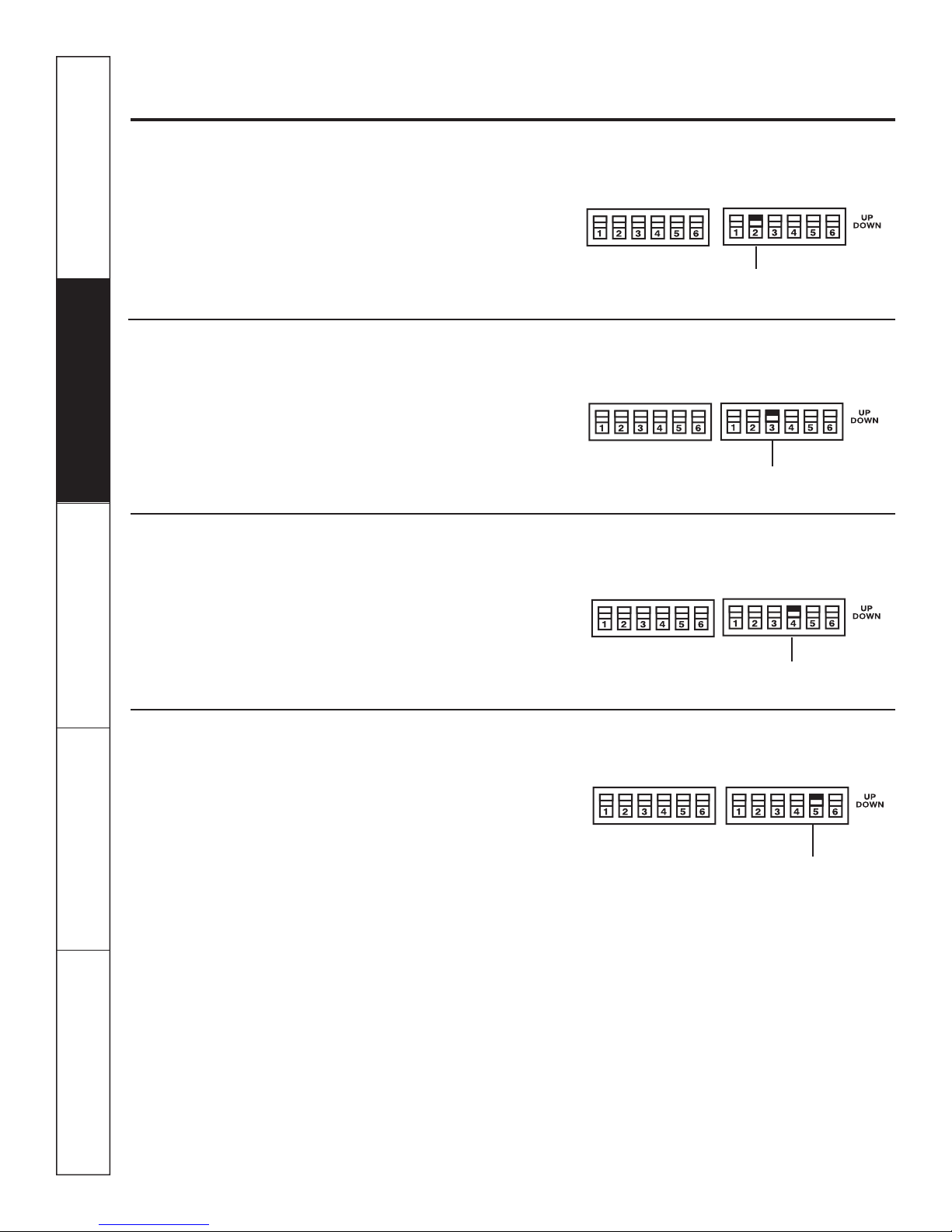
All Electric Heat (Heat pump models only)
When this switch is enabled (UP), heat pump
operation is locked out, causing the unit to provide
only electric resistance heat.
TL1 (H) (Temp. Limit 1–Heat)
TL2 (H) (Temp. Limit 2–Heat)
TL3 (H) (Temp. Limit 3–Heat)
No Function (Reserved for future use)
DUCT (Blower Fan)
OCCUPIED (Occupancy Sensor)
ALL I2R (All Electric Heat)
3
Controls–dip switches.
Freeze Sentinel (Requires room air sensor kit–RAVRMS)
When this switch is enabled (UP), it turns OFF
the freeze sentinel protection feature. With the
switch disabled (DOWN), the freeze sentinel is
activated which automatically provides heat
without user interface. This helps to prevent
plumbing damage by turning the heater
and fans ON at 41° F and OFF at 46° F.
Constant ON Fan
When this switch is enabled (UP), it allows the fan
to run continuously.
Occupancy Sensor (Field Supplied)
FREEZE S (Freeze Sentinel)
CONST FAN (Constant
ON Fan)
When this switch is enabled (UP), it allows the unit
to utilize an infrared motion sensor and a door
switch for occupancy detection. This feature
combined with field devices automatically cycles
the unit between normal operation and a preset
energy management operation.
Duct
The duct select function allows the indoor
fan to be operated at two variable fan speeds.
When this switch is enabled (UP), the unit
automatically selects either high or middle fan
speed (for longer ductwork applications). When
set in the down position, the unit is automatically
operated in either the middle or low fan speed
(for shorter ductwork applications).
OCCUPIED
(Occupancy Sensor)
DUCT
(Blower Fan)
Consumer Support Troubleshooting Tips Care and Cleaning Operating Instructions Safety Instructions
4
Temperature Limiting (Requires room air sensor kit–RAVRMS)
GEAppliances.com
Safety Instructions Operating Instructions Care and Cleaning Troubleshooting Tips Consumer Support
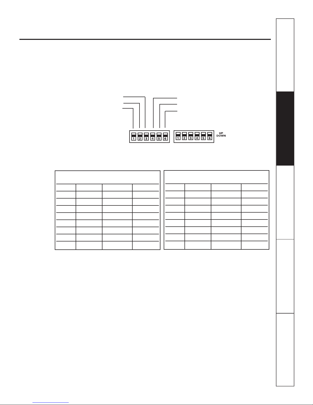
Temperature limiting can reduce energy costs
by limiting the lowest temperature that can be
set for cooling and the highest temperature that
can be set for heating. Temperature limiting is
controlled by switches 1–6 on the top block
TL3 (C) (Temp. Limit 3–Cool)
TL2 (C) (Temp. Limit 2–Cool)
TL1 (C) (Temp. Limit 1–Cool)
Temperature limiting during COOL mode
(all temperatures shown in °F)
UP DOWN Minimum Maximum
NONE 1, 2, 3 60° 85°
1 2, 3 64° 85°
1, 2 3 66° 85°
2 1, 3 68° 85°
2,3 1 70° 85°
1, 2, 3 NONE 72° 85°
1, 3 2 74° 85°
3 1, 2 76° 85°
of auxiliary controls. The first three switches are
used to select the cooling limits. The next three
switches are used to control the heating limits.
TL1 (H) (Temp. Limit 1–Heat)
TL2 (H) (Temp. Limit 2–Heat)
TL3 (H) (Temp. Limit 3–Heat)
Temperature limiting during HEAT mode
(all temperatures shown in °F)*
UP DOWN Minimum Maximum
NONE 4, 5, 6 60° 85°
4 5, 6 60° 80°
4, 5 6 60° 78°
5 4, 6 60° 76°
5,6 4 60° 74°
4, 5, 6 NONE 60° 72°
4, 6 5 60° 70°
6 4, 5 60° 65°
* Not applicable to Cool-Only models
5
Controls—terminal connections.
Controls–Terminal Connections
The terminal connections are located behind
the front case panel through an opening
on the front of the unit.
To access the terminal connections, remove
the front panel by removing the filter, taking out
the four front screws, the upper two screws from
the top of the panel and the shipping screws on
each side, if present. (Discard the four side shipping
screws, if present.)
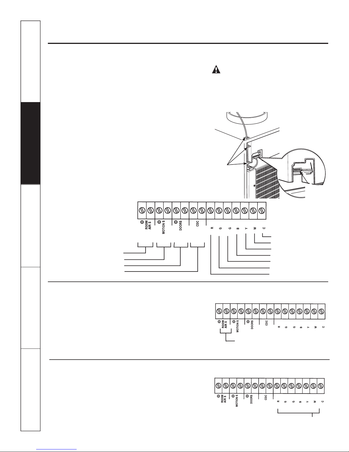
Insert the building hook-up wires into the bottom
of the terminals and tighten screws securely
to make the desired connections.
Route the wires from the terminal connections
through the unit wire guides and out through
the case wire guide.
NOTE: The owner is responsible for setting
the appropriate dip switches and connecting
terminals.
CAUTION:
Improper CDC wiring may damage the Zoneline
electronics or cause erratic Zoneline operation.
No common busing is permitted. A separate wire
pair must be run from each separate controlling
switch to each individual Zoneline.
Route wires
through
wire guides
Terminal
connections
Consumer Support Troubleshooting Tips Care and Cleaning Operating Instructions Safety Instructions
6
24VAC
FAN LO
FAN HI
COMP
REV VA L
AUX HEAT
Room Air Sensor
Motion Sensor
Door Sensor
Central Desk Control
Room Air Sensor (Requires room air sensor kit – RAVRMS)
When connected, the room air sensor will allow
utilization of the temperature limiting and freeze
sentinel features.
NOTE: If GE thermostat RAK148D1, RAK148P1
or RAK164D1, RAK164P1 is used with the unit,
the room sensor kit is not needed for temperature
limiting since this feature is incorporated in the
Room Air Sensor
thermostats.
Hydronic Heating (Requires Hydronic Heating Kit – RAVHW1, RAVHW2 or RAVHW3)
Required connections for hydronic heating kit.
NOTE: R, W, C terminal connections will
also be connected to the remote thermostat
if applicable.
COMMON
Common–Ground
White–Heater
Yellow–Compressor
Black–Reversing Valve
Green–High Speed Fan
Green–Low Speed Fan
Red–24V AC only
24VAC
FAN LO
FAN HI
24VAC
FAN LO
FAN HI
Hydronic Heating
COMP
REV VAL
REV VAL
COMP
AUX HEAT
AUX HEAT
COMMON
COMMON

Motion Sensor (Obtained locally)
The Occupancy Sensor dip switch must be in
the up position to use this feature.
When connected, the wall mounted motion sensor
will detect motion in the room and automatically
cycle the unit between normal operation and
energy management operation.
The door and motion sensors work together
to automatically cycle the unit between normal
operation and energy management operation.
Door Sensor (Obtained locally)
The Occupancy Sensor dip switch must be
in the up position to use this feature.
When connected, the door sensor will detect
when the door in the room is opened or closed.
This feature must be used in conjunction with
the motion sensor.
The door and motion sensors work together
to automatically cycle the unit between normal
and energy management operations.
Motion
Sensor
24VAC
24VAC
Door Sensor
GEAppliances.com
FAN HI
FAN HI
COMP
REV VAL
AUX HEAT
COMP
REV VAL
AUX HEAT
FAN LO
FAN LO
Safety Instructions Operating Instructions Care and Cleaning Troubleshooting Tips Consumer Support
COMMON
COMMON
Central Desk Control
When connected, the unit lock-out is released
and it can be turned ON or OFF with a switch
located at the Central Desk Control. A separate
wire pair must be run from each separate
controlling switch to each individual Zoneline. A
24V AC circuit powers the CDC system. No external
power is required.
Remote Thermostat
The unit will be controlled by a remote
thermostat.
IMPORTANT:
The Zoneline thermostat connections
provide 24V AC only.
If using a digital/electronic wall thermostat,
you must set it to the 24V AC setting. See the
Installation Instructions for the wall thermostat.
NOTICE:
Damage to a wall thermostat or to the
Zoneline electronics can result from improper
connections. Exercise extra attention when
connecting blue and black wires. No line
voltage connections should be made to any circuit
in the thermostat. Isolate all wires in building from
line voltage.
Red–24V AC only
Green–Low Speed Fan
Green–High Speed Fan
Black–Reversing Valve
Yellow–Compressor
White–Heater
Common–Ground
24VAC
FAN LO
FAN HI
COMP
REV VAL
Central Desk Control
24VAC
FAN LO
FAN HI
COMP
REV VAL
AUX HEAT
AUX HEAT
COMMON
COMMON
7

Other features of your Zoneline.
On/Off Switch
The unit on/off switch is located on the front
of the Zoneline.
To turn on the unit, press the top of the switch in.
To turn off the unit, press the bottom
of the switch in.
NOTE: The on/off switch does not remove power
from the unit.
Ventilation Control
The ventilation control lever is located on the left
side of the Zoneline unit, behind the front case
panel.
To access the ventilation control lever, remove
the front panel by removing the filter, taking out
the four front screws, the upper two screws from
the top of the panel and the shipping screws on
each side, if present. (Discard the four side shipping
screws, if present).
When the lever is in the CLOSE position, only the air
inside the room is circulated and filtered.
When the lever is in the OPEN position, some
outdoor air will be drawn into the room. This
will reduce the heating or cooling efficiency.
To close the vent, push the vent lever handle
down, pull it forward and lock it up in place.
To open the vent, push the vent lever handle
down, push it back and lock it up in place.
ON/OFF
switch
Open
Vent control (push
lever down and
pull forward or
back to operate)
Energy Tip: Keep the vent control in the CLOSE
position. The room air will be filtered and circulated.
NOTE: Ventilation openings are not intended to be
the source of make-up air for building ventilation
systems due to the additional heating and cooling
loads generated.
Close
About Heat Pumps (on some models)
Heat pumps can reduce operating costs by
exchanging heat from the outside air—even
when the outside temperature is below freezing—
and releasing that heat indoors.
To get the best economic benefit from your heat
pump, don’t change the room thermostat setting
very often. Raising the heat setting 2–3 degrees
will cause the Zoneline to use its electric heating
elements in order to reach the new temperature
setting quickly.
Do Not Operate the Air Conditioner (cool mode) in Freezing Outdoor Conditions
Air conditioners are not designed for use when
Consumer Support Troubleshooting Tips Care and Cleaning Operating Instructions Safety Instructions
freezing outdoor conditions exist. They must not be
used in freezing outdoor conditions.
8
There is a three minute minimum compressor run
time at any setting to prevent short cycling.
The indoor fan motor starts before the compressor
and stops after the compressor cycles off.
The electric heating elements use much
more electricity than heat pumps and cost
more to operate.

Care and cleaning. GEAppliances.com
Turn off the Zoneline and disconnect the power supply before cleaning.
Indoor/Outdoor Coils
The exhaust coils on the Zoneline should be
checked regularly. If they are clogged with dirt
or soot, they may be professionally steam cleaned
by your GE service center. You will need to remove
the unit from the case to inspect the coils because
the dirt build-up occurs on the exhaust side.
Outdoor coils
Have the coils cleaned regularly.
Drain
Clean the drain system regularly to prevent
clogging.
Safety Instructions Operating Instructions Care and Cleaning Troubleshooting Tips Consumer Support
Base Pan
In some installations, dirt or other debris may
be blown into the unit from the outside and settle
in the base pan (the bottom of the unit).
In some areas of the United States, a “gel-like”
substance may be present in the base pan.
Check it periodically and clean, if necessary.
Air Filters
To maintain optimum performance, change the filter at least every 30 days.
The most important thing you can do to maintain
the Zoneline is to change the filter at least every
30 days. Dirty filters reduce cooling, heating
and air flow.
Changing the filter will: Decrease cost of
operation, save energy, prevent clogged heat
exchanger coils and reduce the risk of premature
component failure.
To remove
and replace
the filter:
NOTICE: Do not operate
the Zoneline without the filter in place. If a filter
becomes torn or damaged, it should be replaced
immediately.
Operating without the filter in place or with
a damaged filter will allow dirt and dust to reach
the indoor coil and reduce the cooling, heating,
airflow and efficiency of the unit.
Remove filter
Unit-mounted filter
Filter
Replacement filters should be purchased
from your local retailer where air conditioner
and furnace accessories are sold.
Filter size required is 20” x 20” x 1".
Filter
Return air grille
Access-panel with
return air grille
9
 Loading...