

Page 1

GE
Intelligent Platforms
Operator Interface Products
6" QuickPanel* View
Basic, Monochrome, Round Bezel
IC754VSB06MTD
IC754VBB06MTD
Hardware User's Guide, GFK-2327B
September 2010
Page 2

Warnings, Cautions, and Notes
as Used in this Publication
Warning
Warning notices are used in this publication to emphasize that hazardous voltages,
currents, temperatures, or other conditions that could cause personal injury exist in this
equipment or may be associated with its use.
In situations where inattention could cause either personal injury or damage to
equipment, a Warning notice is used.
Caution
Caution notices are used where equipment might be damaged if care is not taken.
Note: Notes merely call attention to information that is especially significant to
understanding and operating the equipment.
This document is based on information available at the time of its publication. While efforts
have been made to be accurate, the information contained herein does not purport to cover
all details or variations in hardware or software, nor to provide for every possible contingency
in connection with installation, operation, or maintenance. Features may be described herein
which are not present in all hardware and software systems. GE Intelligent Platforms
assumes no obligation of notice to holders of this document with respect to changes
subsequently made.
GE Intelligent Platforms makes no representation or warranty, expressed, implied, or statutory
with respect to, and assumes no responsibility for the accuracy, completeness, sufficiency, or
usefulness of the information contained herein. No warranties of merchantability or fitness
for purpose shall apply.
* indicates a trademark of GE Intelligent Platforms, Inc. and/or its affiliates. All other
trademarks are the property of their respective owners.
©Copyright 2010 GE Intelligent Platforms, Inc.
All Rights Reserved
Page 3

Contact Information
If you purchased this product through an Authorized Channel Partner, please contact the
seller directly.
General Contact Information
Online technical support and GlobalCare 1http://www.ge-ip.com/support
Additional information 2Hhttp://www.ge-ip.com/
Solution Provider 3Hsolutionprovider.ip@ge.com
Technical Support
If you have technical problems that cannot be resolved with the information in this guide,
please contact us by telephone or email, or on the web at
Americas
4Hwww.ge-ip.com/support
Online Technical Support 5H6Hwww.ge-ip.com/support
Phone 1-800-433-2682
International Americas Direct Dial 1-780-420-2010 (if toll free 800 option is unavailable)
Technical Support Email 7H8Hsupport.ip@ge.com
Customer Care Email 9H10Hcustomercare.ip@ge.com
Primary language of support English
Europe, the Middle East, and Africa
Online Technical Support 11H12Hwww.ge-ip.com/support
Phone +800-1-433-2682
EMEA Direct Dial +352-26-722-780 (if toll free 800 option is unavailable or if
dialing from a mobile telephone)
Technical Support Email 13H14Hsupport.emea.ip@ge.com
Customer Care Email 15H16Hcustomercare.emea.ip@ge.com
Primary languages of support English, French, German, Italian, Czech, Spanish
Asia Pacific
Online Technical Support 17H18Hwww.ge-ip.com/support
+86-400-820-8208 Phone
+86-21-3217-4826 (India, Indonesia, and Pakistan)
Technical Support Email
19H20Hsupport.cn.ip@ge.com (China)
21H22Hsupport.jp.ip@ge.com (Japan)
23H24Hsupport.in.ip@ge.com (remaining Asia customers)
25H26Hcustomercare.apo.ip@ge.com Customer Care Email
27Hcustomercare.cn.ip@ge.com (China)
Page 4

Page 5

Notices
GE Intelligent Platforms reserves the right to make improvements to the products described in
this publication at any time and without notice.
QuickPanel and QuickPanel View are trademarks of GE Intelligent Platforms in the United
States and other countries. Any other trademarks referenced herein are the property of their
respective owners and used solely for purposes of identifying compatibility with the products
of GE Intelligent Platforms.
The 6” QuickPanel View has been tested and found to meet or exceed the requirements of U.S.
(47 CFR 15), Canadian (ICES-003), Australian (AS/NZS 3548) and European (EN55022)
regulations for Class A digital devices when installed in accordance with guidelines noted in
this manual.
Microsoft® requires the following notes be published according to their additional
licensing provisions:
Users are advised that a maximum of ten (10) computers or other electronic devices
may simultaneously connect to, access and use services of the Microsoft Windows®
CE Operating system on the QuickPanel View solely for remote access (including
connection sharing) The ten connection maximum includes any indirect connections
made through ‘multiplexing’, or other software or hardware which pools or
aggregates connections.
Note that the QuickPanel View does not provide any server functionality utilizing
Remote Desktop Protocol (RDP) to remotely connected client computers or devices.
However, it does support connectivity to a remote Microsoft® Terminal Services
server. The server providing these services must meet these restrictions and other
Microsoft licensing requirements as applicable.
Notice Regarding Video Standards
This product is licensed under one or more video patent portfolio licenses such as
and without limitation VC-1 and MPEG4 Part 2 Visual for the personal and noncommercial use of a consumer to:
(i) Encode video in compliance with the standards licensed under such patent
portfolio licenses and/or
(ii) Decode video that was encoded by a consumer engaged in a personal and noncommercial activity and/or was obtained from a video provider licensed to provide
video under such patent portfolio licenses.
Such license extends to this product only and only to the extent of other notices
which may be included in this document. The license does not extend to any other
product regardless of whether such product is included with this licensed product in a
single article. No license is granted or shall be implied for any other use. Additional
information may be obtained from MPEG LA, L.L.C. See http://www.mpegla.com.
Page 6

The FCC requires the following note to be published according to FCC guidelines:
This equipment has been tested and found to comply with the limits for a Class A
digital device, pursuant to Part 15 of the FCC Rules. These limits are designed to
provide reasonable protection against harmful interference when the equipment is
operated in a commercial environment. This equipment generates, uses, and can
radiate radio frequency energy and, if not installed and used in accordance with the
instruction manual, may cause harmful interference to radio communications.
Operation of this equipment in a residential area is likely to cause harmful
interference in which case the user will be required to correct the interference at his
own expense.
Any changes or modifications to the product or installation that are not expressly
approved by GE Intelligent Platforms could void the user's authority to operate the
equipment under FCC rules.
Notices
Industry Canada requires the following note to be published:
This Class A digital apparatus complies with Canadian ICES-003.
The following statements are required to appear for Class I Division/Zone 2
Hazardous Locations.
WARNING – EXPLOSION HAZARD – SUBSTITUTION OF COMPONENTS MAY IMPAIR
SUITABILITY FOR CLASS 1, DIVISION 2.
WARNING - EXPLOSION HAZARD - WHEN IN HAZARDOUS LOCATIONS, TURN OFF
POWER BEFORE REPLACING OR WIRING MODULES.
WARNING - EXPLOSION HAZARD - DO NOT CONNECT OR DISCONNECT EQUIPMENT
UNLESS POWER HAS BEEN SWITCHED OFF OR THE AREA IS KNOWN TO BE NONHAZARDOUS.
Power, input and output (I/O) wiring must be in accordance with Class I, Division 2
wiring methods, Article 501 10(b) of the National Electric Code, NFPA 70 and in
accordance with the authority having jurisdiction.
Users must supply an isolated DC supply to power the QuickPanel models covered by this
manual. The power supply to the QuickPanel must be limited by a slow blow fuse not to
exceed a maximum 100VA. For less than 20Vdc input, the fuse must be rated for no more
than 5A.
For a complete list of agency approvals, please refer to Appendix A.
Page 7

Contents
Welcome.................................................................................................1-1
Getting Started........................................................................................... 1-2
Panel Cutout ................................................................................................1-6
To Mount the QuickPanel View in a Panel .................................................. 1-8
Overview.................................................................................................2-1
QuickPanel View Hardware......................................................................... 2-2
QuickPanel View Software........................................................................... 2-5
Detailed Operation.................................................................................3-1
Touch Screen Display.................................................................................. 3-2
Serial Communication Port........................................................................ 3-15
Ethernet...................................................................................................... 3-23
DIP Switches.............................................................................................. 3-28
Memory...................................................................................................... 3-30
Other Subsystems ..................................................................................... 3-33
Specifications ....................................................................................... A-1
Physical........................................................................................................A-1
DC Power.....................................................................................................A-2
Display .........................................................................................................A-3
Front Panel...................................................................................................A-3
Touch Screen...............................................................................................A-3
CPU..............................................................................................................A-4
Memory........................................................................................................A-4
Communication Ports...................................................................................A-4
Environmental..............................................................................................A-5
Battery..........................................................................................................A-5
Calendar/Clock.............................................................................................A-6
Agency Qualifications ..................................................................................A-6
Diagnostics ........................................................................................... B-1
Power up......................................................................................................B-1
Physical Unit ................................................................................................B-1
GFK-2327B vii
Page 8

Page 9

Chapter
Welcome
1
Congratulations on your purchase of a QuickPanel View. The QuickPanel View
is available in different configurations to suit your requirements, either as a fullfeatured HMI, or as a combination of HMI and controller for local and distributed
control applications. Equally adept in a networked environment or as a standalone unit, the QuickPanel View is the ideal solution for factory floor HMI and
control.
Powered by Microsoft Windows CE.NET
system of choice, the QuickPanel View provides a fast track for application
program development. The commonality with other versions of Windows
simplifies porting your existing program code. Another benefit of Windows CE is
the familiarity of the user interface, shortening the learning curve for operators
and developers alike. The availability of third-party application software makes
this operating system even more attractive.
The 6" QuickPanel View is an all-in-one microcomputer designed for maximum
flexibility. The design, based on an advanced Intel
together a high-resolution operator interface with a variety of I/O options. With
many standard ports and expansion busses from which to choose, you can
connect to most industrial equipment.
TM, today’s embedded operating
® microprocessor, brings
The QuickPanel View is equipped with several memory types to satisfy even
the most demanding applications. A 16 MB section of DRAM is split between
the operating system, an object store, and application memory. A 16 MB
section of non-volatile FLASH memory, functioning as a virtual hard drive, is
divided between the operating system and persistent storage for applicatio n
programs. The many features of the QuickPanel View make it an obvious
choice for a world of applications. Your smart choice will provid e reliable
operation for years to come.
GFK-2327B 1-1
Page 10

1
Getting Started
Basic Setup
Your 6" QuickPanel View is shipped ready for use after a few configuration
steps. To power up all you need to do is connect a DC power supply via the
supplied quick-connect plug. Depending on your application, you may also want
to connect and configure communications ports, as described in chapter 3.
Optional Ethernet Connection
Power Supply
Caution
Electrical Shock Hazard: To avoid personal injury or damage
to equipment, ensure that the DC supply is disconnected
from power and that the leads are not energized before
attaching them to the unit's power supply plug.
1-2 6" QuickPanel* ViewBasic, Monochrome, Round Bezel – September 2010 GFK-2327B
Page 11

1
To Connect a DC Power Supply
1. Using the three screw terminals shown in the following diagram, attach
a 24VDC, 24W power supply to the plug supplied with the QuickPanel
View. See “DC Power” in appendix A for power supply and conductor
specifications.
2. Insert the plug into the power supply socket and securely tighten the
attaching screws.
Note: The torque range for the attaching screws is 4-6 inch/lbs.
Unit Runtime Setup
To download an application to a QuickPanel View unit, you must set up a data
link between it and your development workstation. For more information, see
“Ethernet” in chapter 3 and “Downloading a Machine Edition Project” in the
Machine Edition online help.
GFK-2327B Chapter 1 Welcome 1-3
Page 12

1
Startup
When you first start up the QuickPanel View, a few configuration steps are
necessary.
To start the QuickPanel View
1. Apply AC power to the 24VDC supply.
Once power is applied, the QuickPanel View begins initializing. The first
thing to appear on the display is the splash screen.
2. To skip running any programs included in the StartUp folder, tap Don’t
run StartUp programs.
The splash screen disappears automatically after about 5 secon ds. The
Windows CE desktop then becomes visible.
3. Tap
4. In the Control Panel, double-tap
Start, point to Settings and then tap Control Panel.
Display to configure the LCD
display.
5. In the Control Panel, double-tap
6. In the Control Panel, double-tap
Stylus to configure the touch screen.
Date and Time to configure the
system clock.
1-4 6" QuickPanel* ViewBasic, Monochrome, Round Bezel – September 2010 GFK-2327B
Page 13

1
7. In the Control Panel, double-tap System to configure a network
machine name. Many applications, including Proficy Historian require a
unique machine name. It is recommended procedure to set a unique
network name for the QuickPanel View to avoid future conflicts.
8. In the Control Panel, double-tap
Network and Dial-up Connections to
configure network settings.
9. To save the settings, run
Backup to save any new settings through a
power cycle.
Shutdown
There are no specific dangers associated with a power failure or other
unplanned shutdown of the QuickPanel View. In general, programs are retained
in FLASH memory and user data can be retained in battery-backed SRAM.
Some operating system settings are retained only with user intervention. We
recommend the following procedure to shut down the QuickPanel.
To shut down the QuickPanel View
1. Quit any programs that are running and wait for all file operations to
complete.
2. To save changes to operating system settings (e.g., brightness, touch
screen sensitivity) run
Backup.
3. Run Reboot, as described in chapter 2. When the Windo ws CE desktop
reappears, remove AC power from the 24VDC supply.
GFK-2327B Chapter 1 Welcome 1-5
Page 14
1
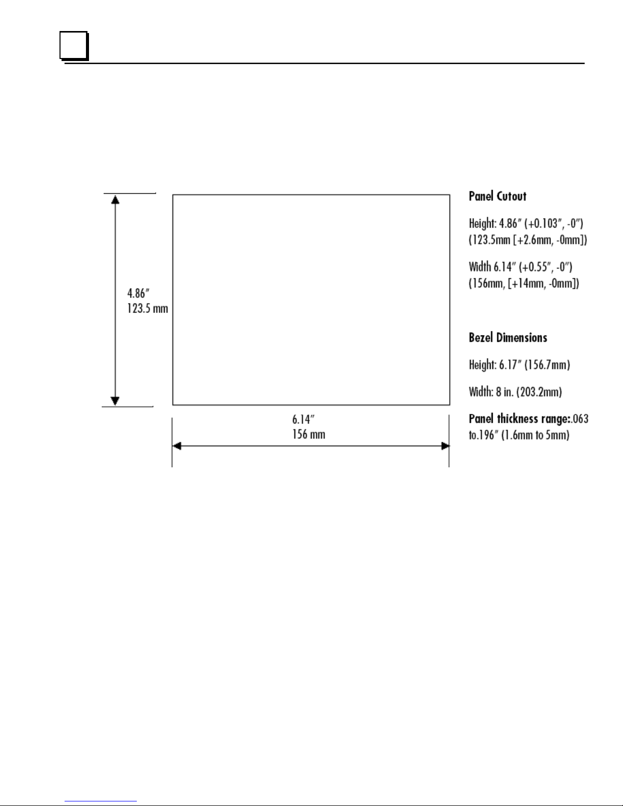
Panel Cutout
For enclosure mounting, cut an opening in the panel according to the following
specifications.
Depth 2.026” (51.5mm)
Notes:
For compliance to NEMA 4, 4x, and 12 qualification, the unit must be
mounted in a comparably NEMA rated (IP56 equivalent) panel or
enclosure.
For compliance to ATEX agency qualification, the unit must be mounted in
an IP66 panel or enclosure.
To avoid gasket degradation, limit repeated insertions or removals of the
unit and retightening of the mounting clips. For full protection, always use a
fresh gasket. Replacement gaskets may be ordered using p art number
IC754ACC06GAS.
1-6 6" QuickPanel* ViewBasic, Monochrome, Round Bezel – September 2010 GFK-2327B
Page 15

1
For adequate ventilation, allow at least 3 inches of space between adjacent
equipment and all sides of the QuickPanel. Ensure that specified conditions
of temperature and humidity are not exceeded.
In outdoor applications, direct sun exposure may impose increased thermal
loads on the QuickPanel leading to excessive temperature rises. Cabinet
design and orientation must be carefully considered to avoid exceeding the
operational temperature limits. These considerations could include shading
for the QuickPanel and its cabinet with awnings or other solar opaq ue
materials, avoiding a due East or West facing of the cabinet, ventilation or
active cooling of the cabinet, or other methods.
The unit will not fit through this cutout with any cables connected, or with the
power supply plug inserted in the socket. To secure the QuickPanel View to a
panel, use the four included mounting brackets. They hook into opening s
located on the top and bottom of the housing.
GFK-2327B Chapter 1 Welcome 1-7
Page 16

1
To Mount the QuickPanel View in a Panel
1. Verify that the gasket is properly seated in the bezel channel, then insert the
unit into the panel cutout.
2. Insert the hook of each mounting bracket in the housing openings as shown
below.
3. Firmly tighten the screws.
Note: The torque range for the mounting bracket screws is 2.6-4.4 inch/lbs
(0.3–0.5 Nm).
The mounting clamps hold the unit in place by tension. No drilling is required.
Do not damage the gasket attached to the back of the QuickPanel. This gasket
prevents shock hazards and damage caused by liquids accidentally entering
the unit after installation.
Also, limit the number of times you remove and reinstall the unit. Too many
installations may cause gasket “set” and degradation of the seal.
1-8 6" QuickPanel* ViewBasic, Monochrome, Round Bezel – September 2010 GFK-2327B
Page 17

Chapter
Overview
2
This chapter provides introductory information on the 6" QuickPanel View
hardware and software with procedures for completing some of the most
common tasks you will encounter.
In this chapter:
QuickPanel View Hardware 2-
Layout Diagram 2Block Diagram 2-
QuickPanel View Software 2-
Windows CE.NET 2Working with Windows CE 2To place a program in the Start menu 2Backup 2-
1H2
2H2
3H4
4H5
5H5
6H6
7H6
8H7
To run the Backup program 2Reboot 2To reboot the system 2System Information 2To run the System Information program 2Emulate PPC 2To use Emulate PPC during an ActiveSync session 2HTTP File Transfer Utility 2To use the HTTP utility 2-
GFK-2327B 2-1
14H10
15H10
16H11
17H11
9H7
10H8
11H8
12H9
13H9
Page 18

2
QuickPanel View Hardware
Layout Diagram
In addition to the primary touch screen interface, the 6" QuickPanel View
supports an RS232/485 serial communications port for co nnection to a wide
variety of controllers. The back of the QuickPanel opens allowing access to the
DIP switches and battery. The following diagram shows the physical layout of
the QuickPanel View and the locations of ports and connections.
Caution
Remove power from the QuickPanel View before opening the
back. Working on a “live” unit may result in damage to
equipment and injury to personnel. Always use anti-static
precautions (i.e. grounded wrist strap) when accessing the
interior of the unit. Do not allow conductive material, liquid or
solid, to contact the electronics of the QuickPanel.
The left LED below the display is green when power is applied and amber if the
backlight fails;
programmable.
Note: Backlights are not field-replaceable.
2-2 6" QuickPanel* ViewBasic, Monochrome, Round Bezel – September 2010 GFK-2327B
the right LED is tricolor (green, red, or amber) and
Page 19

2
Physical Layout of QuickPanel View
GFK-2327B Chapter 2 Overview 2-3
Page 20

2
Block Diagram
The 6" QuickPanel View is based on the XScale microprocessor, and employs
large-scale integration to provide high performance with a small footprint. The
following block diagram illustrates the major functional areas of the QuickPanel
View and the interfaces between them.
2-4 6" QuickPanel* ViewBasic, Monochrome, Round Bezel – September 2010 GFK-2327B
Page 21

2
QuickPanel View Software
Windows CE.NET
Microsoft Windows CE.NET is the operating system for the QuickPanel View. It
is a full 32-bit O/S with a graphical user interface. This operating system is
finding widespread application in hand-held PCs and embed ded HMI’s, such as
the QuickPanel View. From a user’s perspective, the familiar look and feel of
the Windows CE environment shortens the learning curve for those having
experience with Windows 95/98/NT/2000/ME/XP. From the software
developer’s perspective, the CE environment is a subset of the WIN32
application programming interface, simplifying the porting of existing software
from other versions of Windows. The QuickPanel View operating system is
stored in a 10 MB block of FLASH memory and executes directly from flash.
The operating system also uses a small portion of RAM. The operating system
starts automatically following a power-up or reset of the QuickPanel View.
For more on Windows CE visit
0Hwww.microsoft.com/windows/embedded/windowsce/default.mspx.
GFK-2327B Chapter 2 Overview 2-5
Page 22

2
Working with Windows CE
Although the main user input device when working with Windows CE is the
touch screen, it can often be convenient to use keyboard shortcuts, such as
those described in the following table.
Keyboard Shortcut Action
Opens the Windows CE Start menu. Use arrow
CTRL+ESC or
ALT+TAB Starts the Task Manager. Use it to quit
CTRL+ALT+= Starts the touch screen calibration.
SPACEBAR Equivalent to single-tap.
ENTER Equivalent to double-tap. In a dialog box,
TAB In a dialog box, select next control.
keys to select a program and ENTER to run it.
unresponsive programs.
equivalent to OK.
SHIFT+TAB In a dialog box, select previous control.
CTRL+TAB In a tabbed dialog box, open the next tab.
ESC Close dialog box, discarding changes.
ARROW KEYS
In a dialog box, select controls or items from a list
box.
To place a program in the Start menu
1. Start Windows Explorer.
2. Navigate to the program you want to place in the Start menu.
3. Tap the program’s icon to select it.
4. From the Edit menu, choose Copy.
5. Navigate to the ’\Windows\Programs\‘ folder.
6. From the Edit menu, choose Paste Shortcut.
7. To save the settings, run Backup (see page 2-
18H7).
2-6 6" QuickPanel* ViewBasic, Monochrome, Round Bezel – September 2010 GFK-2327B
Page 23
2
Backup
Backup saves changes that you make to the Windows Registry or Desktop to
Flash memory. This utility is required because the QuickPanel View is not
battery powered. Specifically, Backup does the following:
It stores the Windows CE registry (including any control panel settings)
in Flash memory.
It stores any changes (or additions) made to the ‘Windows’ subtree of
the file system in the user block of FLASH memory.
Run Backup whenever you make configuration changes to
the operating system or installed applications, and prior to
shutting down the QuickPanel View.
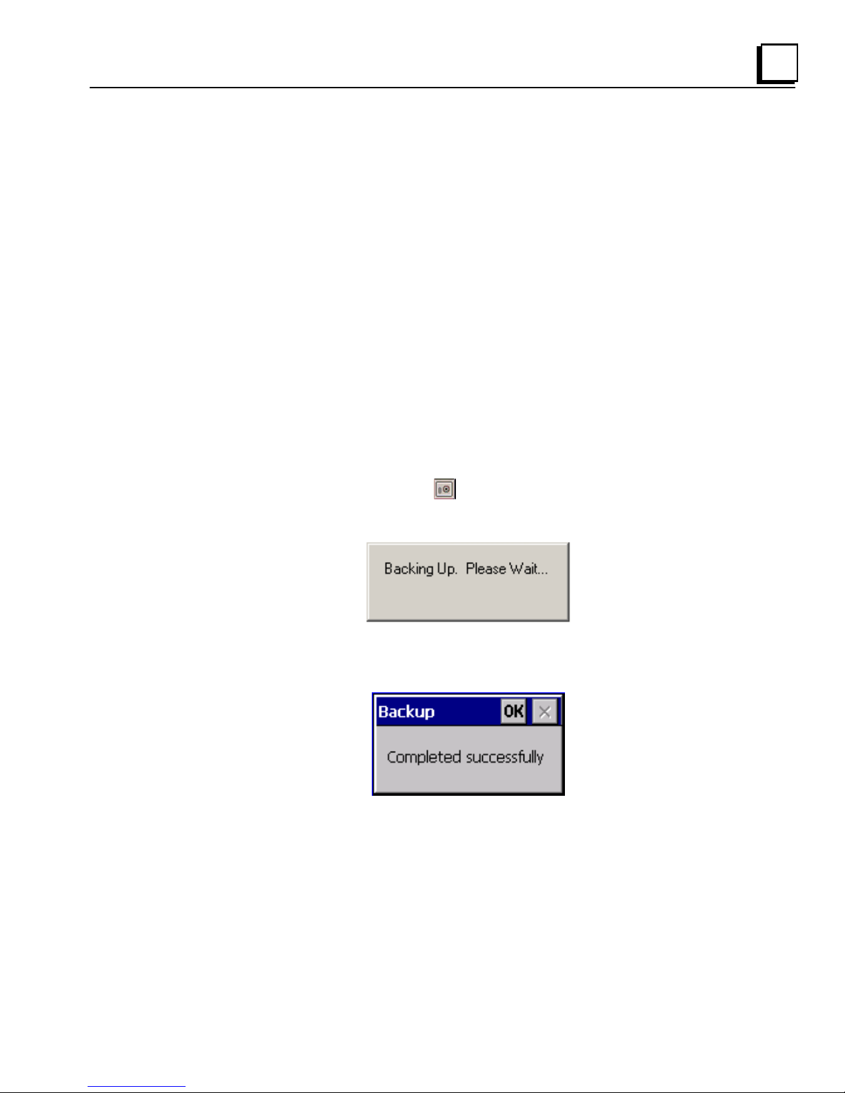
To run the Backup program
1. On the desktop, double-tap Backup.
The Backup dialog box appears.
2. Tap OK.
GFK-2327B Chapter 2 Overview 2-7
Page 24

2
Reboot
Reboot performs a controlled and orderly shut down of the Windows CE
operating system, then restarts the QuickPanel View. This ensures all open
files are closed properly.
To reboot the system
1. To save changes to system configurations, run Backup (see
page 2-
19H7).
2. Tap
Reboot.
A confirmation dialog box appears.
3. Tap Yes.
The operating system reboots.
Start, point to Programs, then the System folder, and tap
2-8 6" QuickPanel* ViewBasic, Monochrome, Round Bezel – September 2010 GFK-2327B
Page 25

2
System Information
System Information is a custom utility that displays a splash screen with the
following information:
Operating System version. For example, ‘Windows CE 5.00’.
Platform. Identifies the host hardware, its version and build number.
Tapping More Info on the splash screen opens the Advanced System
Information window, which provides information such as hard ware version and
serial number, CPU type and specifications, etc. This information can be
especially useful if you are contacting Technical Support.
To run the System Information program
1. On the desktop, double-tap System Information.
The System Information splash screen appears.
2. Tap More Info to open the Advanced System Information window, or
tap Close to continue.
Network information alone can be viewed by double-tapping the
icon displayed on the taskbar for each connection.
GFK-2327B Chapter 2 Overview 2-9
LAN
Page 26

2
Emulate PPC
Emulate PPC is a utility that allows the QuickPanel to emulate a Pocket PC
2003 during an ActiveSync session, enabling the download of third-party
Pocket PC 2003 software.
To use Emulate PPC during an ActiveSync session
1. Start Windows Explorer, double tap Windows, then double tap
EmulPPC.
The Emulate PPC dialog box appears.
2. Start the ActiveSync session. When installation of third party software is
complete, close the dialog box to deactivate Emulate PPC.
2-10 6" QuickPanel* ViewBasic, Monochrome, Round Bezel – September 2010 GFK-2327B
Page 27

2
HTTP File Transfer Utility
The HTTP File Transfer Utility (HFTU) is a small, standalone command line
program that allows you to send and delete files to and from computers over a
network. The HFTU uses the HTTP protocol, so you can even send files to
computers over the Internet.
Run the HTTP utility from a command line prompt, from a batch file (.BAT) or
as an application call in a script. The HTTP utility is an executable (.EXE) file
included in the 6" QuickPanel View operating system.
The HTTP utility currently supports two file transfer commands: COPY and
DELETE.
Note: In order to function, the HTTP File Transfer utility requires both
computers to have web servers that support PUT functionality.
(Most web servers support PUT, including the Proficy Machine
Edition web server installed with the runtimes for View and Logic
Developer - PC.) If in doubt, check the documentation for your web
server.
To use the HTTP utility
1. From the Start menu, choose Programs, then choose Command
Prompt.
The Command Line editor appears.
2. Type commands as required.
GFK-2327B Chapter 2 Overview 2-11
Page 28

2
3. Use the following syntax:
HTTPUTIL COPY source destination
Where “source” is the URL of the source file, and “destination” is the URL of
the destination file. For example:
HTTPUTIL COPY \MyFile.txt http://MyServer/webfiles/MyFileBACKUP.txt
Copies a file called MyFile.txt on drive C: of the local computer to the
webfiles folder under the web server at //MyServer. Note that you can
rename a file as you copy it.
HTTPUTIL DELETE url
Where “url” is the remote URL of the file you want to delete. This URL must
use the “//” or ”HTTP://” syntax. For example:
HTTPUTIL DELETE http://MyServer/webfiles/MyFileBACKUP.txt
Deletes a file called MyFileBACKUP.txt from the webfiles directory under the
web server at HTTP://MyServer.
2-12 6" QuickPanel* ViewBasic, Monochrome, Round Bezel – September 2010 GFK-2327B
Page 29

Chapter
Detailed Operation
3
Touch Screen Display 3-
Adjusting the display brightness, configuring backlight auto turn off,
calibrating the touch screen and setting the double-tap sensitivity.
Keyboard 3-1H10
Using an optional external keyboard and displaying the Soft Input Panel.
Serial Communication Port 3-2H15
Description and pin assignments for the serial port, cabling, and working
with the serial COM port.
Ethernet 3-3H23
Setting an IP address. Setting up access to a Windows network. Accessing
a remote resource on a Windows network.
DIP Switches 3-4H28
Configuring startup behavior
Memory 3-5H30
Adding Flash memory with a CF Card, changing the DRAM memory
allocation, installing additional DRAM.
0H2
Other Subsystems 3-6H33
Accessing the Power Properties control panel, removing and replacing the
internal battery, setting the real-time clock and displaying the time on the
taskbar.
GFK-2327B 3-1
Page 30

3
Touch Screen Display
The QuickPanel View has an integrated flat-panel monochrome display. The
monochrome display is backlit, measures 5.7" diagonally, and uses passive
FSTN technology.
The resolution of the monochrome display is 320 x 240 pixels and 256 sh ades
of gray.
A backlight timer is featured on all models. You can extend backlight life by
turning the backlight off automatically.
320 pixels
240 pixels
3-2 6" QuickPanel* ViewBasic, Monochrome, Round Bezel – September 2010 GFK-2327B
Page 31

3
To adjust the display contrast
1. In the Control Panel, double-tap Display and choose the Contrast
tab.
The Contrast dialog box appears.
2. Drag the Brightness slider between Lowest and Highest.
3. Tap OK to exit the control panel.
4. To save the settings, run
Backup (see page 2-7).
GFK-2327B Chapter 3 Detailed Operation 3-3
Page 32

3
To select backlight auto turn off
1. In the Control Panel, double-tap Display and choose the Backlight
tab.
The Backlight dialog box appears.
2. Select Auto turn off backlight while on external power.
3. Tap OK to exit the control panel.
4. To save the settings, run the Backup utility. (See page 2-7.)
3-4 6" QuickPanel* ViewBasic, Monochrome, Round Bezel – September 2010 GFK-2327B
Page 33

3
Touch Screen
The QuickPanel View display is coupled to a resistive touch panel with 12-bit
resolution. When the QuickPanel View is properly calibrated, this translates into
a grid of touch cells on the face of the display. A blunt stylus should always be
used during calibration for greatest accuracy. During normal operation use of a
finger or a soft and pliable, blunt object is recommended to preserve the
maximum reliability of the touch screen.
240 pixels
320 pixels
GFK-2327B Chapter 3 Detailed Operation 3-5
Page 34

3
To calibrate the touch screen
1. In the Control Panel, double-tap Stylus.
The Stylus Properties dialog box appears.
2. Choose the Calibration tab
3-6 6" QuickPanel* ViewBasic, Monochrome, Round Bezel – September 2010 GFK-2327B
Page 35

3
3. Tap the Recalibrate button.
A cross hair target is displayed.
Note: For greatest accuracy, it is recommended that you use a blunt stylus
when calibrating the touch screen.
4. Follow the directions given to calibrate the touch screen.
GFK-2327B Chapter 3 Detailed Operation 3-7
Page 36

3
5. Tap the screen to preserve the new setting or wait out the time limit to
revert to previous settings.
6. To save the settings, run the Backup utility. (See page 2-7.)
3-8 6" QuickPanel* ViewBasic, Monochrome, Round Bezel – September 2010 GFK-2327B
Page 37

3
To set the double-tap sensitivity
1. In the Control Panel, double-tap Stylus.
The Stylus Properties dialog box appears.
2. Choose the Double-Tap tab.
3. Double-tap the grid to enter a setting.
4. Double-tap the test icon to check the setting.
If the test icon doesn’t change when you double-tap it, double-tap the
grid again.
5. Tap OK to finish.
6. To save the settings, run the Backup utility. (See page 2-7.)
GFK-2327B Chapter 3 Detailed Operation 3-9
Page 38

3
Keyboard
The QuickPanel View can be configured to use a software emulation keyboard
as an operator data input device.
Soft Input Panel
The Soft Input Panel (SIP) is a touch screen version of a standard keyboard,
which can be used in place of a standard hardware keyboard.
An icon in the system tray lets you view or hide the SIP.
Soft Input Panel icon
To show/hide the Soft Input Panel
On the system tray of the task bar, double-tap the icon. The Soft Input Panel
appears/disappears.
Note: When the SIP is visible, it can be dragged around the screen by its
title bar to reveal different parts of the screen that would be
obstructed from view by the SIP.
3-10 6" QuickPanel* ViewBasic, Monochrome, Round Bezel – September 2010 GFK-2327B
Page 39

3
To display the Soft Input Panel icon in the system tray
1. In the Control Panel, double-tap Input Panel.
The Input Panel Properties dialog box appears.
2. Select the Allow applications to change the input panel state check box.
3. Select or clear the Show Input Panel in system tray check box.
4. Tap OK.
5. To save the settings, run the Backup utility. (See page 2-7.)
The Soft Input Panel has two basic configurations: Small key and Large key.
Small Key configuration: provides a standard QWERTY key layout with
numeric keys at the top row as illustrated in the following picture.
Small Key: Lower Case
GFK-2327B Chapter 3 Detailed Operation 3-11
Page 40

3
Upper case characters are accessed by pressing the SHIFT key once. This is
equivalent to holding down the SHIFT key on a conventional keyboard. The
SHIFT key is active while the next key is pressed then reverts back to its
unselected state. The CAP key does the same thing as SHIFT but does not
revert to lower case after another key is pressed. Pressing the CA P key causes
the Soft Input Panel to remain in upper case mode. The CTRL and ALT keys
behave the same as the SHIFT key.
Small Key: Upper Case
Large Key configuration: Provides alphabetic or numeric keys alone. No
numeric keys are displayed at the top of the alpha panel; alpha keys are not
displayed on the numeric panel. As with the small key configuration, upper or
lower case alpha keys can be displayed by using the
SHIFT key.
Large Key: Lower Case
Pressing the 123 key once locks the panel in numeric mode until the 123 key is
pressed again.
3-12 6" QuickPanel* ViewBasic, Monochrome, Round Bezel – September 2010 GFK-2327B
Page 41

3
Large Key: Upper Case
To change key configurations
1. In the Control Panel, double-tap Input Panel.
The Input Panel Properties dialog box appears.
2. From the Current input method list, choose CE Keyboard.
3. Tap Options.
The Soft Keyboard Options dialog box appears.
GFK-2327B Chapter 3 Detailed Operation 3-13
Page 42

3
4. Select Large Keys or Small Keys.
A preview of the key size is displayed on the dialog box.
5. 5. Tap OK twice to finish.
6. To save the settings, run the Backup utility. (See page 2-7.)
To reset the SIP Location
If you accidentally drop the SIP off screen and can’t drag it back on screen,
complete the following steps to reset the SIP to the center of the screen.
1. In the Control Panel, double-tap Input Panel.
The Input Panel Properties dialog box, shown on page 3-
2. Click Reset SIP location.
7H11), appears.
3-14 6" QuickPanel* ViewBasic, Monochrome, Round Bezel – September 2010 GFK-2327B
Page 43

3
Serial Communication Port
The QuickPanel View has one serial data communication port, COM1.
COM1- Serial
The COM1 port is a general purpose bidirectional serial data channel that
supports the EIA232C and EIA485 electrical standards. The COM1 port can be
accessed and configured:
as a direct or dial-up remote networking connection.
from a user-created application utility.
A connection can be configured to reside on a network supp orting a TCP/IP
protocol.
A DB25S (female) connector, mounted on the bottom of the enclosure,
provides standard signals as described in the followin g table.
1 GND - Frame Ground 14 VCC -5VDC, 0.5A
2 TX - (EIA232C) 15 TXB (EIA485)
3 RX - (EIA232C) 16 RXB (EIA485)
4 RTS - (EIA232C) 17 n/c
5 CTS -(EIA232C) 18 CSB (EIA485)
6 DSR - (EIA232C) 19 ERB (EIA485)
7 SG - Signal Ground 20 DTR (EIA232C)
8 DCD - (EIA232C) 21 CSA (EIA485)
9 TRMRXB (EIA485) 22 ERA (EIA485)
10 RXA (EIA485) 23 n/c
11 TXA (EIA485) 24 n/c
12 n/c 25 n/c
13 n/c
Note: Pin 14 is fused with a field-replaceable, 1.0A fast-blow fuse.
GFK-2327B Chapter 3 Detailed Operation 3-15
Page 44

3
Operating COM1 in EIA-485 Two-Wire Mode
Use of COM1 in EIA-485 two-wire mode requires additional control of the port
to ensure that the transmitter is turned off at the appropriate times to allow
other connected stations to transmit and to avoid collisions of transmissions.
This additional control avoids transmission collision s, which are possible in
two-wire mode because all the transmitters are tied together.
This function is normally carried out by the software driver included as part of
the application software and is not part of the Windows CE operating system.
Those who don't have the appropriate driver or who wish to develop their own
driver, will need to design their software driver to control the port appropriately
in the EIA-485 two-wire mode.
In all QuickPanel View models, the RTS (Request to Send) control signal is
brought out on the COM1 connector but is also conne cted to the dri v er enable
input (active low) of the EIA-485 transceiver device on COM1. When not
transmitting, RTS is de-asserted (turned off) to disable the transmitter and
asserted (turned on) before transmission to enable the transmitter.
The receiver is hardwired to always be enabled. In two-wire mode, the
communication software has to discard any returned message that it receives
while transmitting.
Activating RTS is possible using the standard Windows API for the COM ports
by appropriately setting the Device Control Block (DCB) for the port, then using
the resulting handle to the port to manipulate this signal.
When relying on the Windows API to control RTS, one entire message should
be written to the port at one time, not byte-wise, to ensure that RTS does not
toggle in the middle of a transmitted message.
3-16 6" QuickPanel* ViewBasic, Monochrome, Round Bezel – September 2010 GFK-2327B
Page 45

3
Recommended Cabling for TIA/EIA422 or TIA/EIA485
The COM1 port on the QuickPanel View provides connections to devices that
support either TIA/EIA422 or TIA/EIA485. These electrical standards specify a
differential signaling technique that provides high data rates, lon g distances and
good noise rejection. The standards do not address signal encoding (protocol),
connectors, or cabling. However, certain characteristics of these devices’
interfaces should be considered to ensure reliable connections.
Connections
Interconnect
media
Termination
Connect nodes in a daisy chain fashion. Do not connect in other
arrangements, especially "star." The standards do not specify the maximum
number of nodes or devices that can be connected to a TIA/EIA 422 or 485
network. Instead, the standards limit the number of electrical connections by
specifying that a maximum of 32 unit loads may be connected. The
QuickPanel View presents one unit load.
Always use twisted pair cabling and group complime ntary signals into
conductor pairs; TXA with TXB, for example. Use a cable with a characteristic
impedance of 100 ohms to 120 ohms. A wire gauge of 24 AWG is commonly
used. Maximum cable length is 4,000' (1,219.2m), but may be less due to
cable impedance, connection quality, data rates, and other factors.
Always provide proper termination at each end of the 422/485 network. The
QuickPanel View provides built-in termination resistance when pin #9
(TRMRXB) is connected to pin #10 (RXA).
Caution: Do not terminate every node. Only terminate the end nodes.
GFK-2327B Chapter 3 Detailed Operation 3-17
Page 46

3
Grounding
Shielding
A signal return path between transmitting and receiving devices must be
provided. This return path is separate from the Rx and Tx data lines and the
other 422/485 signals supported by the QuickPanel View, and may be
provided by a separate conductor in the cable. Connect both ends of the
signal return conductor to Signal Ground (pin #7). Shielding or use of a
twisted pair for this connection is not necessary.
For installations where all devices are in the same cabinet and have the same
ground potential between devices, connecting Signal Ground between all the
devices on the 422/485 network is adequate to ensure prop er voltage levels
at the devices.
However, if there is a difference in ground potential between devices, such as
when the devices are in widely separated cabinets, signal grounds on a
422/485 network should not be tied together. The cable shield an d signal
ground should be connected together at only one device, closest to the earth
ground connection.
The signal and frame grounds of the QuickPanel View are capacitively
coupled, but in some devices these ground references are connected
together. Connect Signal Ground (pin #7) to Frame Ground (pin #1) and then
to earth ground on the QuickPanel View only in the circumstance where the
other devices separate their signal and frame grounds and the QuickPane l
View is the only device with frame and signal ground connected to earth
ground.
Shielded cable is required for compliance with CE Mark and FCC
requirements. The cable shield should be connected to the metal connector
shell or by pin 1 of the QuickPanel 25-pin serial connector. Shield and signal
ground (pin 7 of the 25pin connector or pin 5 of the 9-pin serial co nnector)
should not be connected directly together.
Caution
Do not connect Signal Ground (pin #7) to Frame Ground (pin #1) on
the QuickPanel View, except in the specific and limited
circumstances noted in the Grounding section above.
3-18 6" QuickPanel* ViewBasic, Monochrome, Round Bezel – September 2010 GFK-2327B
Page 47

3
Working with the COM Port
To add a new remote networking connection
1. From the Start menu, tap Settings and then Network and Dialup Connections.
The Connection window appears.
2. Double-tap
Make New Connection.
The Make New Connection window appears.
3. Type a name for the new connection.
4. Choose a connection type. If you are configuring a modem, choo se
Dial-Up Connection. If you have a device, select Direct Connection.
GFK-2327B Chapter 3 Detailed Operation 3-19
Page 48

3
5. Tap Next. The Modem or Device dialog box appears, dependin g on the
connection type.
or
6. From the list, choose the device or modem you want to use. (If a serial
CF card is inserted, it is available in the device list.)
You can configure your device or TCP/IP Settings at this time if you
wish.
7. Tap Finish for direct connection (Device dialog box) or Next for dial-up
(Modem dialog box).
If you are adding a dial-up connection the following dialog box appears.
8. Type the destination Country/region code, Area code, and Phone
number in the appropriate boxes.
9. Select or clear the Force Long Distance or Force Local check boxes.
10. Tap Finish.
3-20 6" QuickPanel* ViewBasic, Monochrome, Round Bezel – September 2010 GFK-2327B
Page 49

3
To change the default device properties
1. From either the Device or Modem dialog box, tap Configure.
The Device Properties dialog box appears.
2. In the Port Settings tab, choose settings for all connection preferences.
3. If the connection is for terminal emulation, select or clear the terminal-
related check boxes.
You can use the QuickPanel View to emulate a terminal attached via a
modem link (Hayes compatible) to COM1. A terminal emulation
definition is added as a unique session.
GFK-2327B Chapter 3 Detailed Operation 3-21
Page 50

3
To change the default TCP/IP settings
1. Obtain correct TCP/IP settings from your network administrator.
2. From the Device, Modem, PPPoE Connection, or VPN Connection
dialog box, tap TCP/IP Settings.
The TCP/IP Settings dialog box appears.
3. Enter the TCP/IP settings from your network administrator and then
click OK.
3-22 6" QuickPanel* ViewBasic, Monochrome, Round Bezel – September 2010 GFK-2327B
Page 51

3
Ethernet
The QuickPanel View is equipped with a 10BaseT/100BaseTx auto-negotiate
Ethernet port (IEEE802.3), and you can connect an Ethernet network cable
(unshielded, twisted pair, UTP CAT 5) to the unit via the RJ45 connector on the
bottom of the enclosure. LED indicators on the port indicate channel status.
Access to the port is possible either by Windows CE network communications,
or by your custom application. The following diagram shows the location,
orientation, and pin out of the Ethernet port.
1 TX_D1 +
2 TX_D1 3 RX_D2 +
4 B1_D3+
5 B1_D36 RX_D2 7 B1_D4+
8 B1_D4-
GFK-2327B Chapter 3 Detailed Operation 3-23
Page 52

3
The QuickPanel View provides two methods for setting an IP address:
DHCP (Dynamic Host Configuration Protocol). This is the default
method that is carried out automatically.
Note: There must be a DHCP server on the connected network for a
valid IP address to be assigned. Contact your network
administrator to ensure correct DHCP server configuration.
Manual method. You uniquely specify the numeric addresses for the
QuickPanel View, the Subnet Mask, and the Default Gateway (if
applicable).
Note: Use a crossover cable to connect the QuickPanel View directly
to a PC. When connecting to a LAN HUB, use a
straight-through cable. Contact your network administrator for
further information.
To set an IP address
1. From the Control Panel, tap Network and Dial-up Connections.
The Connection window appears.
3-24 6" QuickPanel* ViewBasic, Monochrome, Round Bezel – September 2010 GFK-2327B
Page 53

3
2. Select a connection and choose Properties. The Built-in
Ethernet Port Settings dialog box appears.
3. Select a method:
Obtain an IP address via DHCP (automatic).
Specify an IP address (manual).
4. Enter the IP Address, Subnet Mask and Default Gateway numbers
obtained from your network administrator (manual method only).
5. Tap OK.
6. To save the settings, run the Backup utility. (See page 2-7.)
After setting an IP address for the QuickPanel View, you can access
any network drives or shared resources for which you have permission.
GFK-2327B Chapter 3 Detailed Operation 3-25
Page 54

3
To set up access to a Windows network
1. In the Control Panel, double-tap System. The System Properties
dialog box appears.
2. On the Device Name tab, in the Device name box, type a unique name
for your QuickPanel View. In the Device description box, type a
description.
3. Tap OK.
4. In the Control Panel, double-tap
Owner. The Owner Properties
dialog box appears.
3-26 6" QuickPanel* ViewBasic, Monochrome, Round Bezel – September 2010 GFK-2327B
Page 55

3
5. On the Network ID tab, type your User name, Password and Domain.
6. Tap OK.
7. To save the settings, run the Backup utility. (See page 2-7.)
Using Windows CE Explorer, you can now access anything on your local
network for which you have permission.
To access a remote resource on a Windows network
1. Start Windows Explorer. The Explorer window appears.
2. Type in the Address box, or choose from a list, the path to a remote
resource.
For example ‘\\MyRemoteComputer\MyFolder’ specifies the folder
named ‘MyFolder’ on a computer with the name ‘MyRemoteComputer’.
3. Press ENTER.
The resource specified is displayed as a collection of files and folders. It
can take a few moments to retrieve the data from your local network.
Note: You can use the NET command from the command prompt to map
a network resource to the QuickPanel View for frequent access.
The resource then appears in the
GFK-2327B Chapter 3 Detailed Operation 3-27
Network folder.
Page 56

3
DIP Switches
The QuickPanel View is equipped with four DIP switches that control separate
functions.
DIP switches are set to “OFF” by default in the factory. DIP switch 2 is the
Force Startup switch. Turning this switch on forces the startup applications to
run when the operating system is started.
When the switch is set to “OFF”, the QuickPanel View operates normally,
displaying the startup splash screen. You can skip running the startup
applications by tapping the “Don’t run StartUp Programs” button on the startup
splash screen.
3-28 6" QuickPanel* ViewBasic, Monochrome, Round Bezel – September 2010 GFK-2327B
Page 57

When the switch is set to “ON”, the startup programs are forced to run and the
“Don’t run Startup Programs” button is not available on the startup splash
screen.
Note: Do not adjust switches other than switch 2. They are reserved for
factory functions.
3
To configure startup behavior
Caution
Disconnect power from your DC power supply before opening
the QuickPanel View. Working on a “live” unit may result in
damage to equipment and injury to personnel. Always use
anti-static precautions (i.e. grounded wrist strap) when
accessing the interior of the unit.
Caution
Do not allow conductive material, either liquid or solid, to
contact the electronics of the QuickPanel.
1. Open the back cover of the QuickPanel View.
2. Locate the DIP switches and set DIP switch 2 to “ON”. The startup
applications are now forced.
Note: Do not adjust the other switches. They are rese rved for factory
functions.
GFK-2327B Chapter 3 Detailed Operation 3-29
Page 58

3
Memory
The QuickPanel View supports a variety of memory subsystems to ensure the
requirements of your application are met. All system memory is tied directly to
the microprocessor’s address and data busses for fastest access.
Flash Memory
This 16 MB block of non-volatile memory is the main long-term program
storage for the QuickPanel View, operating like a virtual hard drive from the
point of view of Windows CE. It is divided into two areas, of which only one is
accessible from Windows CE Explorer. The
represents a 6 MB block of memory available for long-term storage of user
application programs. Another 10MB block is used to store the Windows CE
operating system and is not directly accessible from Windows CE Explorer.
Flash Storage folder
The operating system and all user application programs are transferred from
Flash to DRAM for execution. Any user additions to the
retained in
FLASH memory has a limited write-cycle lifetime. That is, the physical memory
devices wear out after approximately 100,000 cycles (minimum), so it is
advisable to limit file operations such as copy, delete, etc.
The write cycle is much slower for FLASH than it is for other portions of RAM,
therefore FLASH is not recommended for the storage of program variables, or
any data items whose values are dynamic.
Flash Storage when the Backup utility is run.
Windows folder are
Caution
Do not remove power while the system is writing to flash
memory, such as when downloading a Proficy Machine
Edition project. Removing power while writing may lead to
data loss and file system corruption. To ensure the system
completes writing to flash and closes all files, see
“Shutdown” in chapter 1.
3-30 6" QuickPanel* ViewBasic, Monochrome, Round Bezel – September 2010 GFK-2327B
Page 59

3
DRAM Memory
The QuickPanel View is equipped with approximately 16 MB of dynamic RAM,
which is split between an object store for temporary file storage and the main
memory for running programs.
Typically, compressed programs stored in FLASH are expanded and moved to
DRAM for execution. Temporary storage of program variables or data files is
also provided by DRAM—any data stored in DRAM will not be retained through
a power cycle.
The split between program memory and storage memory may be adjusted as
necessary to make more room for one or the other, depending on your specific
application needs. For example, if you find that an application is short of
memory, use the System Properties dialog box to alter DRAM memory
allocation.
Caution
Setting Program Memory too low may prevent additional
applications from starting, or may cause currently running
applications to fail due to lack of memory. Setting Storage
Memory too low may prevent the saving of files into the
object store portion of the file system, which may also cause
application failures.
GFK-2327B Chapter 3 Detailed Operation 3-31
Page 60

3
To change the DRAM memory allocation
1. In the Control Panel, double-tap System. The System Properties
dialog box appears.
2. On the Memory tab, drag the slider to divide the DRAM into Storage
and Program memory.
The amount of memory allocated to and used by each area is shown on
the dialog box. The amount of memory allocated to and used by each
area is displayed numerically. The blue bar indicates the current
amount of unallocated DRAM and determines the boundaries within
which the slider can move.
3. Tap OK to apply the new setting.
4. To save the settings, run the Backup utility. (See page 2-7.)
Boot Loader ROM
The Boot Loader ROM provides 512 KB of non-volatile storage for the
QuickPanel View’s initialization program. This program configures the
QuickPanel View hardware then starts the operating system’s execution. This
memory is not accessible from Windows CE Explorer, nor should any attempts
be made to modify the contents of this ROM.
3-32 6" QuickPanel* ViewBasic, Monochrome, Round Bezel – September 2010 GFK-2327B
Page 61

3
Other Subsystems
Power Management
The QuickPanel View’s Power Properties control panel displays th e status of
the backup battery. The Battery Very Low Or Missing
taskbar when the battery is either missing or very low.
icon appears in the
To access the Power Properties control panel
1. In the Control Panel, double-tap Power. The Power Properties
dialog box appears.
GFK-2327B Chapter 3 Detailed Operation 3-33
Page 62

3
Battery Backup
Auxiliary backup power for the real-time clock and SRAM is provided by a
non-rechargeable, internal lithium battery (+3VDC, BR2032), ensuring that no
loss of data occurs when the main DC supply is removed. Backup power is
enabled or disabled by installing or removing the battery, accessed via the rear
panel as shown in the following illustration.
Caution
Remove power from the QuickPanel View before opening the back. Working on
a “live” unit may result in damage to equipment and injury to personnel. Always
use anti-static precautions when accessing the interior of the QuickPanel View.
Do not allow conductive material, liquid or solid, to contact the electronics of the
QuickPanel.
Caution
Do not allow conductive material, liquid or solid, to contact
the electronics of the QuickPanel.
3-34 6" QuickPanel* ViewBasic, Monochrome, Round Bezel – September 2010 GFK-2327B
Page 63

3
To remove the internal battery
1. Disconnect AC power from the DC supply.
2. Open the rear access panel.
3. Release the battery by gently lifting it from the completely exposed side,
past the small protrusions. To avoid breaking the battery retainer clips,
do not apply excessive upward pressure.
4. Slide the battery out of its carrier, noting the arrow on the carrier
indicating the direction of removal.
To install a new battery
1. Disconnect AC power from the DC supply.
2. Open the rear access panel.
Note: Battery must be installed with positive ( + ) side up.
3. To install the battery, insert one side of the battery into the upper side of
the battery clip, then press the other side into the clip until snaps into
place.
Warning
Replace battery with Panasonic BR2032 only. Use of another
battery may present a risk of fire or explosion.
Warning
Battery may explode if mistreated. Do not recharge,
disassemble or dispose of in fire.
GFK-2327B Chapter 3 Detailed Operation 3-35
Page 64

3
Real-time Clock
The QuickPanel View has a programmable real -time clock capable of reporting
the current time in Year/Month/Day/Hour/Minute/Second. The time is set from
the Windows CE interface and retained through a power cy cle if battery backup
is available. Daylight saving time is enabled by a check box within the dialog
box. The time can be displayed in the system tray on the task bar.
To set the real-time clock
1. In the Control Panel, double-tap Date/Time.
The Date/Time Properties dialog box appears.
Note: Tap Apply after making changes in any box.
2.
To modify the date, select the Date/Time tab.
3. Tap the year to choose a new year; tap the month to choose a new
month.
4. Tap a date to specify the day of month.
5. From the Time Zone box, choose your zone.
3-36 6" QuickPanel* ViewBasic, Monochrome, Round Bezel – September 2010 GFK-2327B
Page 65

3
6. Select Auto Adjust DST to configure the clock to automatically
compensate for daylight savings time.
7. In the Current Time box, adjust the hours, minutes and seconds.
8. Tap OK to finish.
9. To save the settings, run the Backup utility. (See page 2-7.)
To display the time on the taskbar
1. From the Start menu, choose Settings and then Taskbar and
Start Menu Properties.
The Taskbar Properties dialog box appears.
2. On the Taskbar Options tab, select Show Clock.
3. Tap OK.
An hours and minutes display now appears in the taskbar.
Clock Display
GFK-2327B Chapter 3 Detailed Operation 3-37
Page 66

Page 67

Appendix
Specifications
A
See page Asafety.
0H6 for a list of agency approvals for environmental service and
Physical
Enclosure dimensions
(actual – see “Panel Cutout”
in chapter 3 for cutout dimensions)
Bezel dimensions
Weight 2.5 lb (1.16 kg)
Height: 4.86 in. (126 mm)
Width: 6.14 in. (156 mm)
Depth: 2.026 in. (51.5 mm)
Height: 6.17 in. (156.7 mm)
Width: 8 in. (203.2 mm)
Depth: 0.85 in. (21.5 mm)
GFK-2327B A-
1
Page 68

A
DC Power
Input Voltage 12 to 30 VDC
Power Dip Tolerance -30% nominal input voltage, 10msec.
Insulation Resistance
Real Power 9 W
Connector (Vendor, p/n)
Power Supply Conductor Size 12 to 18 AWG
268Mohm @ 1000V frame ground to 0V
366Mohm @ 1000V frame ground to 24V
Power requirement nominal for startup when DC supply
is already powered and stable. Applying power to the
supply while connected to the QuickPanel View
increases total inrush current requirements. In this case,
supply should be rated at 10x the nominal startup
current. Otherwise, an interposing relay or switch must
be used between the DC supply and the QuickPanel
View.
NOTE: For compliance with UL 1604, switches or relays
inline with the DC power wiring cannot be used in
hazardous locations.
Phoenix Contact, 1777992
NOTE: The torque range for the attaching screws is 4-6
inch/lbs.
For compliance to CE Mark, the isolated frame ground
must be connected.
Recommended frame ground connection is via the
shortest possible route, using 14 AWG.
A-2 6" QuickPanel* ViewBasic, Monochrome, Round Bezel – September 2010 GFK-2327B
Page 69

A
Display
Size 5.75" (14.6 cm) diagonal
Colors 256 shades of gray
Resolution 320 x 240
Fabrication Passive FSTN
Backlight Cold Cathode Fluorescent (CCFL) -rated half life: 50,000
hours.
Note: Backlight is not field replaceable.
Luminance 100 NITS
Front Panel
Bezel Material Valox 3706
For material specifications, visit
www.gepolymerland.com
Membrane Material Lexan HP60
For material specifications, visit geplastics.com
LEDs
Left Power status indicator (green with power applied, red if
either backlight fails)
Right Programmable tri-color (green, red, amber)
Touch Screen
Type Resistive, 12 bit
Resolution (after calibration)
GFK-2327B Appendix A Specifications A-3
X axis: 320 cells
Y axis:240 cells
(after calibration)
Page 70

A
CPU
Processor Intel XScale PXA255
Clock speed 200 MHz
Memory
Flash 16 MB
DRAM 16 MB
ROM 512 KB (Boot loader)
Communication Ports
Ethernet
Serial COM1 EIA232C/EIA485, DP25S (female)
Speed 300 bps -115200 bps
Mounting hardware M2.6 jackscrew
Fuse 1.0A, 125V fast blow cartridge type
IEEE 802.3
10 BaseT/100 Base TX
RJ45 connectors
Two status LEDs
Maximum cable length: 30m
Littlefuse part #154001
A-4 6" QuickPanel* ViewBasic, Monochrome, Round Bezel – September 2010 GFK-2327B
Page 71

A
Environmental
14°F to 140°F Operating Temperature*
(-10°C to 60°C)
Operating Humidity 10% to 85% non-condensing
-4 to 158°F Storage Temperature*
-20 to 70°C
Storage Humidity 10% to 85% non-condensing
NEMA Rating 4, 4x and 12
Applies to front of installed unit when mounted in a
comparably rated NEMA panel (NEMA 4 is
approximately equivalent to IP66; visit
www.nema.org)
UL Rating Type 4X
Suitable for mounting on the flat surface of a type
4X enclosure.
Operational Vibration
IEC 60068-2-6
10–57Hz, 0.012" peak to peak displacement
57–500Hz, 1.0g acceleration
IEC 60068-2-27 Operational Shock
15g, 11ms (sine wave)
• Rated temperature limits refer to the ambient air temperature immediately
surrounding (less than 3” or 7.6 cm) the QuickPanel inside the enclosure in which
the QuickPanel is mounted. Additional provisions for remaining within the stated
limits must be considered where additional, external thermal loads are im posed
on the QuickPanel. These could include large heat produci ng motor drives, or
power supplies in the same cabinet or in outdoor applications involving direct sun
exposure.
Battery
Type BR2032 (3V, 190mAh, lithium)
Approximate 5 years
GFK-2327B Appendix A Specifications A-5
Page 72

A
Calendar/Clock
Resolution 1 second
Accuracy ±2 to 3 minutes per month
Retention Life of battery
Agency Qualifications
Model number: ES0620
Description
North American Safety for
Industrial Control Equipment
North American Safety for
Hazardous Locations Class I,
Div. 2, Groups A, B, C, D
Enclosures for Electrical
Equipment
Explosive Atmospheres
Directive European Safety for
Hazardous Locations
Equipment Group II,
Category 3
Low Voltage Directive
European Safety for Industrial
Control Equipment
Electromagnetic Compatibility
Directive European EMC for
Industrial Control Equipment
Agency Standard
or Marking
UL 508/C-UL Certification by Underwriter’s
Laboratories to UL standard and
equivalent CSA standard
UL 1604/C-UL Certification by Underwriter’s
Laboratories to UL standard and
equivalent CSA standard
UL 50 Certification by Underwriter’s
Laboratories to Type 4X
ATEX (when
mounted in an IP66
enclosure)
CE
Certification in accordance with
European directives; refer to
Declaration of Conformity and
Independent 3
Certificate.
Self-declaration in accordance with
European directives; refer to
Comments
rd Party Assessment
Declaration of Conformity
CE
Certification by competent body in
accordance with European directives;
refer to
Declaration of Conformity
The agency approvals listed above and on the Declaration of Conf ormities
are believed to be accurate; however, a product’s agency approval s should
be verified by the marking on the unit itself.
A-6 6" QuickPanel* ViewBasic, Monochrome, Round Bezel – September 2010 GFK-2327B
Page 73

Appendix
Diagnostics
B
The tables contained in this appendix can be used to identify and remedy
problems that can occur with the 6" QuickPanel View
Power up
Problem Suggested remedy
Blank screen
No power: Check all power connections to the
QuickPanel View.
Note: Left LED glows amber when backlight fails.
Physical Unit
Problem Suggested remedy
Slow or sluggish touch
response.
Touch screen does not work
reliably in corners or touch
areas activate just outside their
borders.
GFK-2327B B-
Ensure that configured I/O or communications
channels such as serial or Ethernet are operating
without error. These errors can cause higher system
overhead leading to delayed response to touch
inputs.
Ensure that flash drives, internal or external, are
operating without error. If the flash drives are highly
fragmented or corrupted, reads and writes to the
drive can experience significant delays leading to
delayed response to touch inputs. Corrupted
external flash drives may be corrected with Storage
Manager. See “Storage Manager” in chapter 3.
Touch screen may need recalibration. Select Start,
then Settings, Control Panel, Stylus, and then the
Calibration tab. Follow the on-screen directions.
1
Page 74

Page 75

Agency Approvals, A-6
Index
F
A
Flash memory
operation, 3-30
Front panel
specifications, A-3
B
Backup, 2-7
Basic setup, 1-2
Battery, 3-34
removing, 3-35
specifications, A-5
Block diagram, 2-4
Boot loader ROM, 3-32
C
Calendar/clock
specifications, A-6
Clock
operation, 3-36
setting, 3-36
Communication port
operation, 3-15
Communication ports
specifications, A-4
CPU
specifications, A-4
D
Diagnostics, B-1
Dimensions
bezel, A-1
cutout, 1-6
module, A-1
DIP Switches, 3-28
Display
operation, 3-2
specifications, A-3
DRAM memory, 3-31
E
Emulate PPC, 2-10
Environmental requirements, A-5
Ethernet port
operation, 3-23
G
Gasket
part number, 1-6
Getting started, 1-2
H
HTTP File Transfer Utility, 2-11
I
IP address
setting, 3-24
L
Layout diagram, 2-2
M
Memory, 3-30
specifications, A-4
O
Operating system, 2-5
P
Physical unit
diagnostics, B-1
Power management, 3-33
Power requirements, A-2
Power up
diagnostics, B-1
GFK-2327B Index-1
Page 76

Index
Reboot, 2-8
Remote resource
accessing, 3-27
Runtime setup, 1-3
Shutdown, 1-5
Software, 2-5
Specifications, A-1
Startup, 1-4
configuring, 3-29
System Information, 2-9
R
S
Technical Support. See page iii
Touch response
diagnostics, B-1
Touch Screen Display
operation, 3-2
Troubleshooting, B-1
Windows network
access, 3-26
T
W
Index-2 6" QuickPanel* ViewBasic, Monochrome, Round Bezel–September 2010 GFK-2327B
 Loading...