

Page 1

Adjustable Dual Technology Sound Sensor
Installation Instructions
Product summary
The sensor (60-834-95, 60-765-43) is a dual technology glassbreak detector that uses a single microphone for detecting both
flex and audio frequencies. Since glass breaking must be both
detected and verified, false alarms are virtually eliminated.
The sensor detects glass breakage of windows within 25 feet.
How It Works
The microphone is sensitive to different frequencies. It detects
both the ultra-low frequencies produced by a blow to a glass
window and the higher frequencies produced by breaking
glass.
The audio technology remains inactive until the microphone
detects a blow to the glass. Once this happens the microphone
must also detect the frequency of breaking glass, within a
defined time-window after the flex circuitry detects a blow to
the glass. Only then does the sensor go into alarm.
The sensor is powered by two 3.6V Lithium AA batteries
(included).
The sensor can be used with the glass types and thicknesses
shown in Table 1 below.
Table 1: Glass types and thicknesses
Glass type Thickness (inches)
Plate 3/32
Tempered 1/8
Laminated 1/8
Wired 1/4
For the sensor to work properly, the glass size must be at least
10-7/8” x 10-7/8”.
Tools Needed
• Small Phillips Screwdriver
• Small Flathead Screwdriver
• Screws and Anchors (included)
• Small Needle-Nose Pliers
• M4 or M5 Screw
• Sound Sensor Tester (part number 13-332)
Programming
The following steps describe the general guidelines for
programming (learning) the sensor into panel memory. Refer to
the specific panel installation instructions or reference manual
for complete programming details.
1. Set the panel to the program mode.
2. Proceed to the LEARN SENSORS menu.
3. Select the appropriate sensor group and sensor number
assignments.
4. When prompted by the panel to trip the sensor, activate
the sensor tamper by opening the sensor door.
P/N 466-17
5. Exit program mode.
26 • REV E • 16FEB11 1
Page 2
Y
(
)
w
Installation
Guidelines
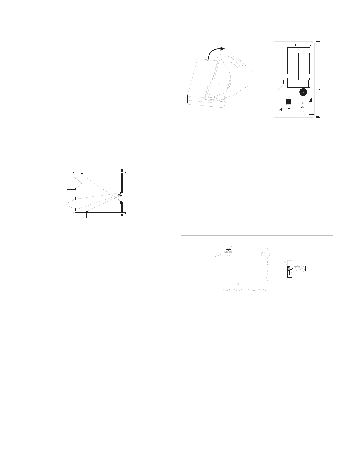
Determine the best mounting location for the sensor using the
following guidelines:
• Mount the sensor on the ceiling or on a wall at least 7 feet
from the floor with a direct and unobstructed line-of-sight
of the protected glass.
• Mount the sensor within 25 feet of the glass to be
protected (see Figure 1 below).
Figure 1: Sensor mounting locations
POOR LOCATION
FULLY OPENED DOOR CAN
BLOCK SENSORS VIEW
POOR LOCATION,
HIGH RISK OF
DOOR SLAM
OPTIMUM
LOCATIONS
SATISFACTORY
LOCATION
Note: Curtains, blinds, and other window coverings can absorb
energy from breaking glass. For example, heavy curtains will
effectively block the sound signal. In these cases, mount the
sensor behind the window covering next to or above the
window.
M
MU
I
X
MA
'
5
2
M
U
M
I
AX
M
M
U
'
5
M
2
I
X
A
M
'
25
SATISFACTOR
LOCATION
Figure 2: Opening cover to locate and remove cover screw
-
+
3.6V
3.6V
LITHIUM
LITHIUM
AA
AA
BATTERY
BATTERY
TEST MODE
OFF
ON
AUDIO
2 SNES
LED ENABLED
SCREW
1 SNES
ALARM
FLEX
2. Remove the sensor cover by first pulling up at the top of
the cover then lift up at the bottom. Set the sensor cover
aside.
Note: Steps 3 and 4 provide instructions on how to enable
the wall tamper switch. For commercial UL listed systems
the wall tamper switch must be used. If not using the
tamper switch feature, move on to step 5.
3. Enable the wall tamper switch by removing the plastic tab
on the back of the sensor using the needle-nose pliers
(see Figure 3 below).
Figure 3: Wall tamper switch
Wall
Tamper
Arm
Plastic Tab
Wall
Tamper
Arm
Scre
• Do not mount the sensor next to air ducts, forced air fans,
or bells measuring 2 inches (or larger) in diameter
Back of Sensor
• Do not mount the sensor near doors and windows that can
be slammed (see Figure 1 above).
Do not mount the sensor where furniture may be placed
•
between the glass and the sensor.
• Do not mount the sensor on posts, free-standing or
otherwise.
4. Screw the M4 or M5 screw into the wall or ceiling so that it
will make contact with the wall tamper arm.
5. Place the sensor base at the desired location on the wall
or ceiling (over tamper screw if installed) and mark the
narrow portion of the mounting holes (see Figure 4 on
e 3)
pag
• Do not mount the sensor where a door can be closed
between the sensor and the glass or where an open door
may obstruct sensor line-of-sight (see Figure 1 above).
Mounting the Sensor
Mount the sensor using the following procedure:
1. Open the sensor door and remove the cover screw using
a Phillips screwdriver (see Figure 2 below).
2 Adjustable Dual Technolog
(Side View)
y Sound Sensor Installation Instructions
Page 3
Y
t
4: Mounting hole locations
Figure
POOR LOCATION
FULLY OPENED DOOR CAN
BLOCK SENSORS VIEW
Sensor Testing with the FG-700 Glass Break Simulator
1. Set the panel to the dealer sensor test mode.
2. Open the sensor door (to view LEDs).
POOR LOCATION,
HIGH RISK OF
DOOR SLAM
OPTIMUM
LOCATIONS
SATISFACTORY
LOCATION
M
MU
I
X
MA
'
5
2
M
U
M
I
AX
M
M
U
'
5
M
2
I
X
A
M
'
25
SATISFACTOR
LOCATION
6. Insert screws part way into anchors (if necessary) or wall.
7. Place the sensor base on the screws and slide the narrow
portion of the mounting holes onto the screws.
8. Gently tighten the screws to secure the sensor in place.
Testing
Use the following procedures with the Sound Sensor Tester to
test the audio and RF ranges simultaneously. The
recommended tester is a FG-701 Glass Break Simulator,
however instructions for the FG-700 Glass Break Simulator are
also provided. For additional testing information, refer to the
tester operating instructions. For UL listed systems, the
installer should test the unit at least once a year.
Note: Do not test when the sensor is in normal mode.
Table 2 below describes LED indicator conditions.
Note: The only LEDs are for audio and alarm. The flex
LED hole should be empty.
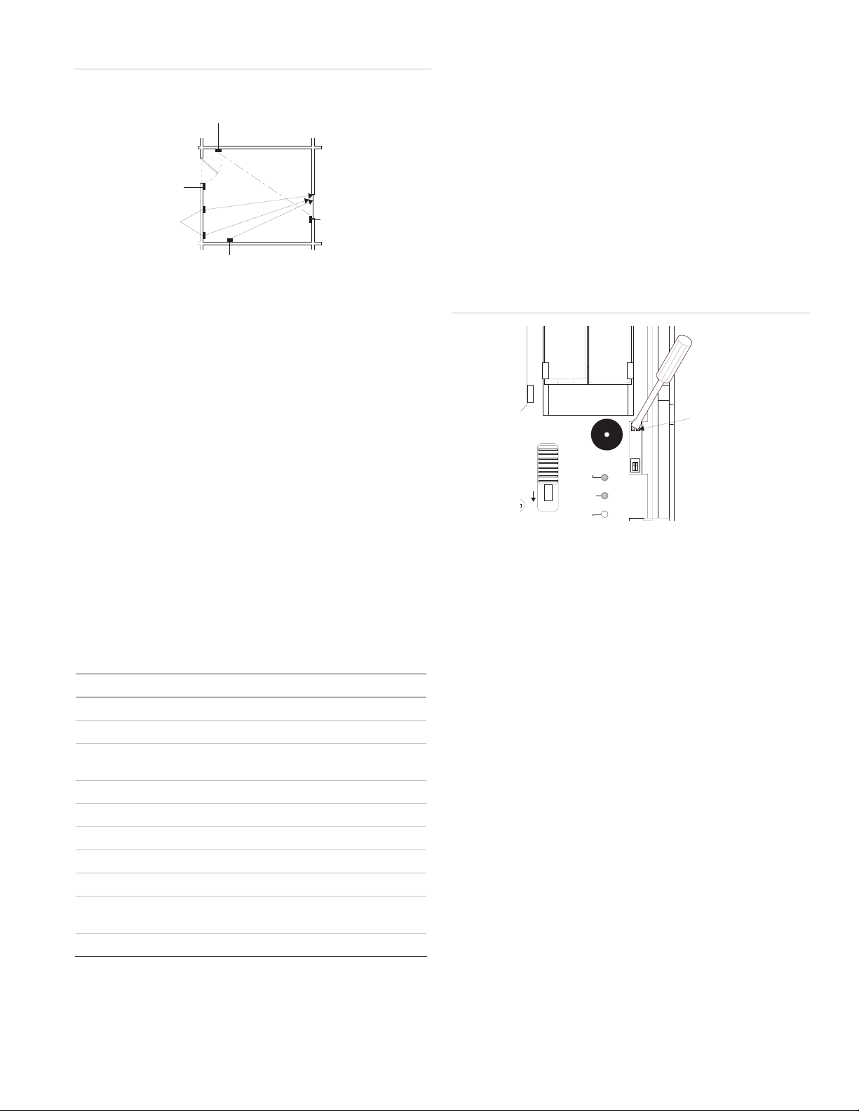
3. Place the sensor in test mode by shorting out the silver
test points on the sensor board using a small flathead
screwdriver (see Figure 5 below). When the sensor is in
test mode the gree
Figure 5: Shorting out the sensor board test points
LED ENABLED
n LED blinks once per second
AUDIO
ALARM
X
3.6V
TEST MODE
OFF
ON
2 SNES
1 SNES
Silver Tes
Points
3.6V
Note: The sensor returns to normal mode after 5 minutes. To
immediately return the sensor to normal mode short out the
silver test points a second time.
1. Hold the tester at the farthest point of the glass to be
protected (25 feet maximum).
Table 2: LED indicator conditions
Condition Green LED Red LED
2. Place the tester setting switches to “Flex” and “Temp.”
3. Within 30 seconds of arming the tester, generate a signal
Normal OFF OFF
Normal, event detected Flicker OFF
Normal, event detected
Flicker Flash 5 seconds
and alarm in memory
Normal, break detected OFF ON 5seconds
4. Listen for interior siren beeps to determine acceptable
Power up self-test ON 1 second ON 1 second
Trouble detected Flash ON/OFF Flash OFF/ON
Low battery Flash ON/OFF Flash ON/OFF
Test Mode Flash once per second OFF
Test Mode, event
Flicker OFF
detected
Test Mode, alarm Flash once per second ON 5 seconds
Sensor Testing with the FG-701 Glass Break Simulator
1. Set the panel to the dealer sensor test mode.
2.
Adjustable Dual Technolog
y Sound Sensor Installation Instructions 3
by striking the glass with your hand or a cushioned tool.
The tester will automatically generate a burst of glass
breaking sound, and the red LED on the sensor should
light to indicate an alarm condition.
range (see panel installation instructions).
Note: If the sensor response is unacceptable, change the
position or location of the sensor and re-test.
Open the sensor door (to view LEDs).
Note: The only LEDs are for audio and alarm. The flex
LED hole should be empty.
Page 4
3. Place the sensor in test mode by placing the tester setting
switches to “Activate” and “Man,” then press the red button
on the tester (within 15 feet of the sensor). The tester
emits a low frequency buzzing sound. When the sensor is
in test mode the green LED blinks once per second.
Note:
The sensor returns to normal mode after 5 minutes.
To immediately return the sensor to normal mode, place
the tester setting switches to “Activate” and “Man,” then
press the red button on the tester. The tester emits a low
frequency buzzing sound and the green LED stops
flashing.
Hold the tester at the farthest point of the glass to be
4.
protected (25 feet maximum).
Place the tester setting switches to “Test” and “Flex.”
5.
6. Within 30 seconds of arming the tester, generate a signal
by striking the glass with your hand or a cushioned tool.
The tester will automatically generate a burst of glass
breaking sound, and the red LED on the sensor should
light to indicate an alarm condition.
Listen for interior siren beeps to determine acceptable
7.
range (see panel installation instructions).
Table 3: Sensitivity settings
Sensiti
vity SENS 1 switch SENS 2 switch Approximate
Max Off Off 25 feet
Med On Off 15 feet
Low Off On 10 feet
Lowest On On 5 feet
coverage
4. Reinstall the batteries.
5. Place the sensor in test mode (see appropriate range
testing section).
6.
Turn on any heating/air-conditioning system, and any
other equipment in the sensor vicinity. Observe the green
audio LED for one minute with equipment running.
Excessive subsonic (inaudible) noise typically produced by
air handling systems may cause the green audio LED to
flash randomly.
If the LED flashes randomly, decrease the sensitivity
7.
according to the sensitivity settings in Table 3 above.
Specifications
Note: If
the sensor response is unacceptable, change the
position or location of the sensor and re-test.
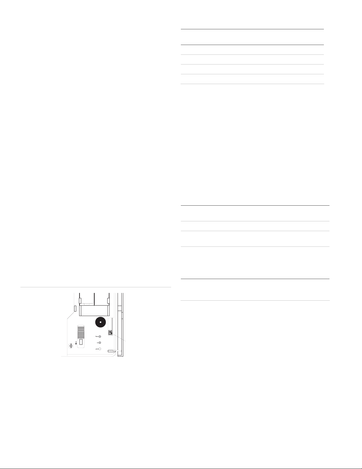
Adjusting the sensitivity
The sensitivity is set at the factory and should only be adjusted
when necessary. Adjust the sensitivity using the following
procedure.
Figure 6: LED sensitivity switches
TEST MODE
OFF
ON
AUDIO
2 SNES
1 SNES
Sensitivit y
Switches
Note: Sensitivit
removed.
LED ENABLED
ALARM
FLEX
y changes must be made with sensor batteries
Compatibility 60-834-95—all 319.5 MHz. Learn Mode panels
60-765-43—all 433 MHz. Learn Mode panels
Power source Two 3.6VDC Saft or Tadiran AA Lithium Batteries.
Operating
temperature range
Dimensions 4.75” x 4.13” x 1.25” (L x W x D)
32°F - 110°F
Regulatory information
Manufacturer UTC Fire & Security Americas Corporation, Inc.
1275 Red Fox Rd., Arden Hills, MN 55112-6943,
USA
Contact information
For contact information, see www.utcfireandsecurity.com or
www.interlogix.com.
Copyright © 2011 UTC Fire & Security. All rights reserved.
1. Open the sensor door.
2. Remove the batteries.
3. Use a small screwdriver to move the sensitivity switches to
the desired setting (see Figure 6 above). Sensitivity
settings are shown in Table 3 below.
4 Adjustable Dual Technology Sound Sensor Installation Instructions
 Loading...