

Page 1
Door/Window & Long Life Door/Window Sensors
Installation Instructions
Product Summary
Door/Window (60-362) and Long Life Door/Window (60-641)
sensors can be installed on doors, windows, or other devices that
open and close. Under normal use, door and window sensors
transmit open (TRIP) and close (RESTORE) signals to the panel
each time a magnet connects with or breaks away from a sensor.
Also, each sensor sends a supervisory signal to a panel every 64
minutes. The door/window sensor is powered by a 3.6V lithium
battery.
Note: The Long Life Door/Window Sensor battery cannot be
replaced. If you experience a low-battery condition, you
must return the sensor to GE Security for a full
replacement.
Installation Guidelines
• Mount sensors within 100 feet of the panel.
• For door mounts, mount the sensor to a door frame and the
magnet to the door.
• Mount sensors with screws; do not mount with double-sided
tape or other adhesive products.
• To avoid damage, mount each sensor a minimum of five
inches above the floor.
• For Long Life sensors, do not remove the jumper from the
circuit board. The sensor cannot operate without the jumper.
• Use spacers (not included) to keep sensors and/or magnets
away from metal surfaces such as flashing or foil wallpaper.
Door/Window Sensor Spacers:
White: Part No. 60-189
Brown: Part No. 60-191
Magnet Spacers:
White: Part No. 60-188
Brown: Part No. 60-190
466-1022 Rev. E
February 2005
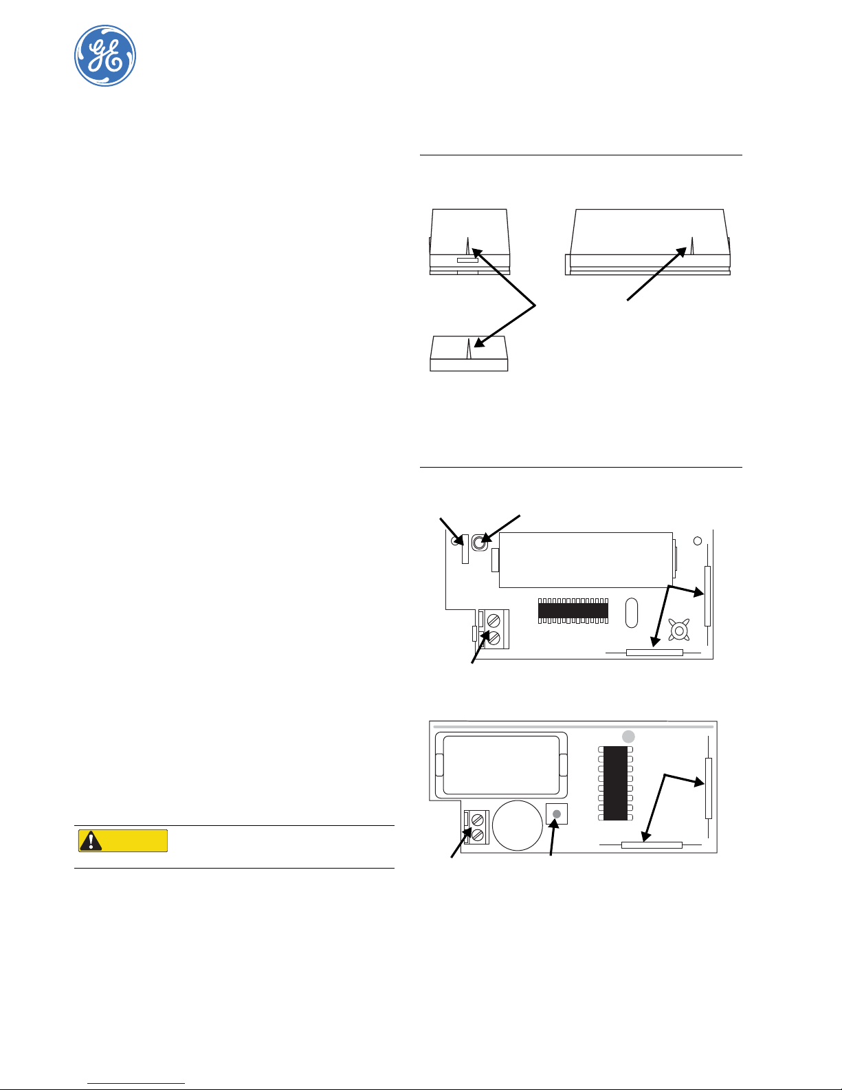
Figure 1. Locating Sensor Alignment Marks
Sensor End
Alignment Marks
Magnet
2. Remove sensor cover.
3. Remove the circuit board from the sensor base. Pull back on
the plastic tab and lift the battery to release the circuit board.
4. Remove unused reed switches. Clip the leads as close to the
board as possible (see Figure 2).
Figure 2. Door/Window Sensor Circuit Boards
Jumper Tamper Switch
3.6V Battery
Sensor Side
Reed Switch
• Remove internal reed switches not in use.
• Do not mount sensors near areas with excessive metal or
electrical wiring, or near areas with excessive moisture.
• Do not mount sensors where temperatures exceed 120°F.
Tools Needed
• #6 Flathead screws
• Phillips and Slotted screwdrivers
• Wire cutter/stripper
• Sensor/magnet spacers (not included)
Installation
CAUTION
1. Decide on a horizontal or vertical mount. Next, locate the
alignment marks on the mounting surface (see Figure 1).
The marks indicate reed switch locations. Remove unused
reed switches (Step 4).
.
You must be free of static electricity while
handling electronic components. Touch a bare
metal surface before touching the circuit board.
Terminals
Terminals
3.6V Battery
Tamper Switch
60-641 (Old)
Reed Switch
60-632 (Old)
Page 2
Door/Window & Long Life Door/Window Sensors
2
Installation Instructions
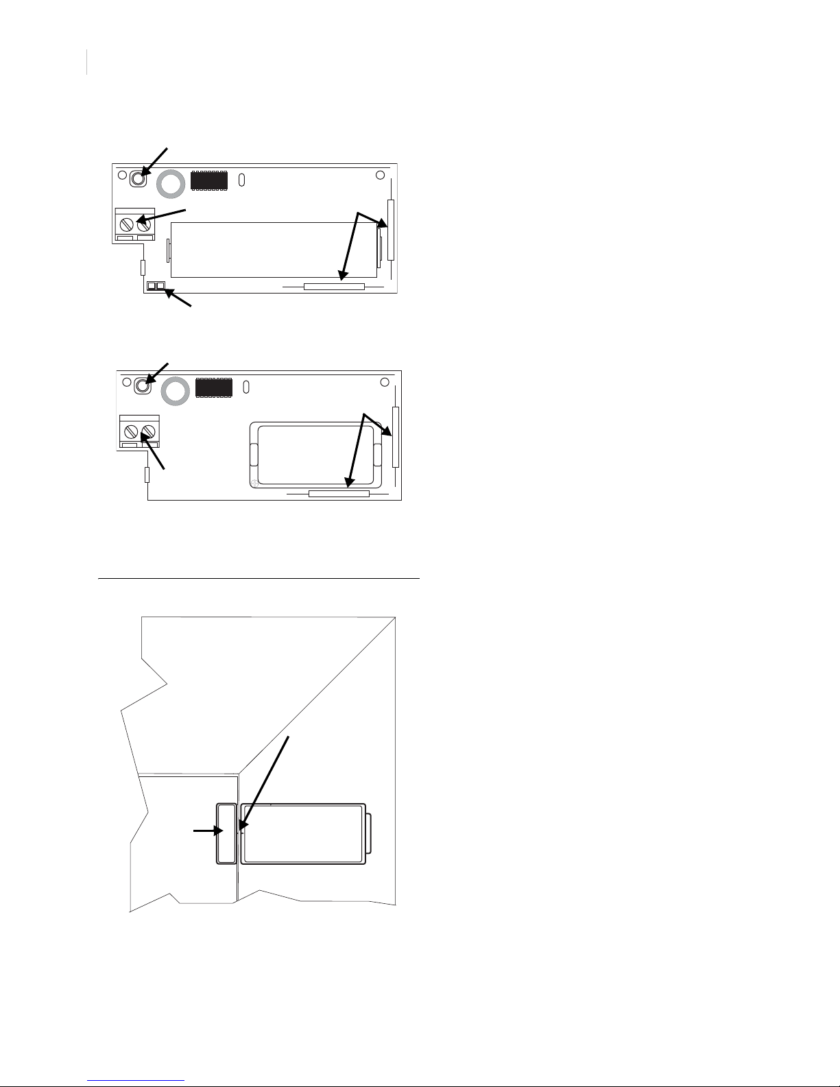
Fig 2. Continued from Page 1
Tamper Switch
Term in al s
3.6V Battery
Jumper
Tamper Switch
Terminals
Reed Switch
60-641 (New)
Reed Switch
3.6V Battery
60-632 (New)
5. Mount the sensor base. Next, remove the magnet from the
base and mount it no more than 3/8” from the sensor base
(see Figure 3).
Figure 3. Sensor Base and Magnet Mounted on a Door and Door Frame
Connecting External Switches
Door and window sensors can be connected to normally open
(close on alarm) or normally closed (open on alarm) external
switches. For normally open switches, wire multiple sensors in
parallel; for normally closed switches, wire multiple sensors in
series.
Do not use both a built-in reed switch and an external switch on
the same door/window sensor. For high-security installations,
remove both reed switches when external switches are connected
to sensor terminals.
Note: For UL-listed installations, use only a normally closed
configuration.
Materials Needed
• Sealed, external reed switches with a minimum 250 mS
open or close on alarm.
• Stranded, 22-gauge wire.
Installation Guidelines
• Do not use solid-core wire or mechanical switches.
• For remote device connections, do not use a sensor’s builtin reed switches.
• Do not connect fast pulse devices such as a Window Bug to
a door or window sensor.
• Do not exceed a wire length of 25 feet for 22-gauge,
stranded wire runs. For UL-listed installations, do not
exceed a wire length of three feet between a sensor and
external device.
• Do not exceed a length of six feet for untwisted wire pairs.
• Connect up to five switches and one alarm screen to a door/
window sensor.
• Do not route wire runs parallel to other electrical wires. If a
parellel wire run cannot be avoided, ensure a minimum
distance of 18” exists between the nearest electrical wiring.
• When necessary, cross electrical wires at a 90° angle.
Alignment Marks
Magnet
Door
Note: Mount the magnet so that it does not interfere with door or
window openings. Do not use double-sided tape or other
adhesive products.
Sensor
Door Frame
6. Connect the circuit board to the base.
7. Replace the sensor cover.
Programming
The following provides a general guideline for programming a
door/window sensor into panel memory. Refer to specific panel
Installation Instructions for complete programming details.
1. Set panel to Program Mode.
2. Enter the Learn Sensors menu. Next, select the appropriate
sensor group and number assignments.
3. Set external switches to Alarm (open for normally closed
circuits; closed for normally open circuits).
4. Remove sensor cover. The sensor tamper switch trips.
5. Exit Program Mode.
6. Replace sensor cover.
Testing
The following provides a general guideline for testing a door/
window sensor. Refer to the specific panel Installation Instruc-
tions for complete testing details.
1. Set panel to Sensor Test Mode.
2. Trip the sensor. Listen for interior siren beeps to determine
appropriate responses (refer to the panel Installation
Instructions).
The Long Life Door/Window Sensor has a built-in power saving
feature that automatically turns on when a sensor is tripped two
or more times within a four minute period.
When the power saving feature is on and a sensor is tripped, the
sensor transmits only half of the regular data rounds.
Page 3

3
For example, during a sensor test you normally expect to hear up
to eight data rounds. Because the power saving feature is on, you
may only hear up to four data rounds.
To ensure a sensor is within range of a panel, leave the sensor in
the closed (non-alarm) condition for five minutes prior to tripping it. This allows the sensor to disengage the power-saving
feature and provides for more accurate test results.
Battery Replacement
When the system indicates a low sensor battery, immediately
replace the battery. Use only exact replacement batteries (see
Specifications).
1. Remove sensor cover.
2. Remove battery and dispose as required by local laws.
3. Insert replacement battery. Observe polarity (see Figure 4).
4. Perform sensor test.
Figure 4. Observing Battery Polarity
Positive Terminal
Specifications
Model No. 60-362: Door/Window Sensor
Compatibility All GE Security 319.5 MHz Learn Mode panels
Power Source 60-362: 1/2 AA 3.6V Saft or Tekcell Lithium Battery
Storage Temperature -30° to 140°F (-34° to 60°C)
Operating Temperature 10° to 120°F (-12° to 49°C)
Maximum Humidity 90%, non-condensing
Transmit Range Minimum of 500 feet in open-air
UL Listings UL 1023 – Household Burglar Alarm Units
60-641: Long Life Door/Window Sensor
60-641: AA 3.6V Lithium Battery
and Systems
Notices
This device complies with FCC Rules Part 15. Operation is subject to the
following two conditions:
1. This device may not cause harmful interference.
2. This device must accept any interference that may be received,
including interference that may cause undesired operation.
Changes or modifications not expressly approved by GE Security can
void the user’s authority to operate the equipment.
FCC ID: B4Z-503A-DWS
GE Security
1275 Red Fox Road
Arden Hills, MN 55112
www.gesecurity.com
Technical Support
T: 800.777.2624
F: 651.779.4890
 Loading...