

Page 1
g
GE Digital Energy
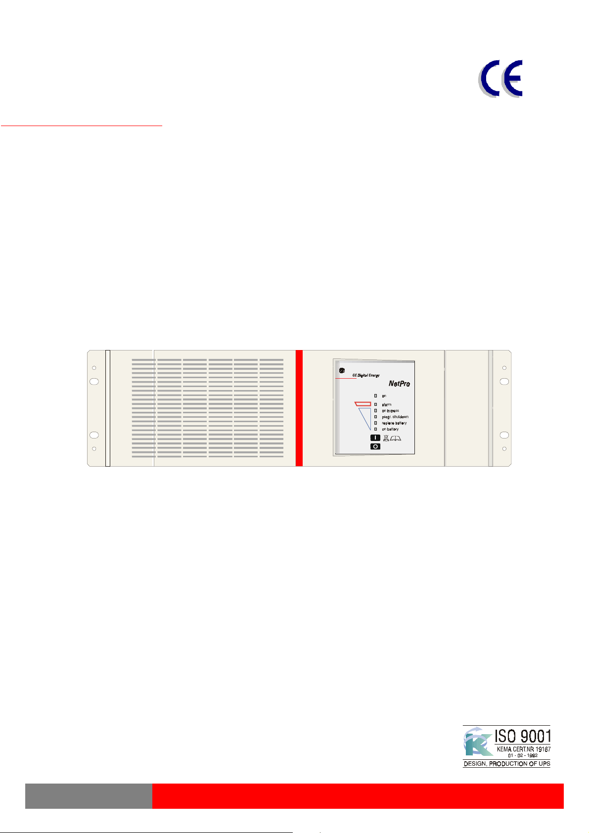
NetPro 19"
Uninterruptible Power Supply
600 - 1500 VA
Manufactured by:
GE Digital Energy
General Electric Company Telephone +41 (0)91 / 850 51 51
CH – 6595 Riazzino (Locarno) Fax +41 (0)91 / 850 51 44
Switzerland Website www.gedigitalenergy.com
NetPro 19" UPS
Technology for the Digital World.
ver 3.0 - GB
Page 2

g
GE Digital Energy
GB
USER MANUAL
NetPro 19"
Uninterruptible Power Supply
Uninterruptible Power Supply
Uninterruptible Power SupplyUninterruptible Power Supply
600 - 1500 VA
600 - 1500 VA
600 - 1500 VA600 - 1500 VA
Please read these instructions carefully before installation and start-up of the
NetPro 19” UPS. Keep this manual in a safe place for future reference.
CONTENTS
1 INTRODUCTION.............................................................................................2
1.1 Introduction
1.2 Safety Rules
1.3 Transport / Storage
2 INSTALLATION...............................................................................................2
2.1 Installation Rules
2.2 Installation Procedure
3 OPERATION...................................................................................................4
3.1 Start-up
3.1.1 Start-up, mains available
3.1.2 Start-up, mains not available (‘battery start’)
3.2 Use: Normal Operation
3.2.1 Normal operation conditions
3.2.2 Load indication
3.2.3 Auto-off (no-load shutdown)
3.2.4 Automatic bypass switch
3.2.5 Switching off
3.3 Use: Status and Alarm Indications
3.3.1 Charger on
3.3.2 On-line: normal operation
3.3.3 On battery
3.3.4 Battery low (end of runtime)
3.3.5 On bypass
3.3.6 Bypass out of limits
3.3.7 Overload
3.3.8 Overtemperature
3.3.9 Replace battery
3.3.10 Programmed shutdown
3.4 Use: Setup Mode
3.5 Battery Management
4 COMMUNICATION .........................................................................................9
4.1 RS232 Port
4.2 Relay Interface Card (option)
4.3 SNMP Interface Card (option)
5 OPTIONAL FEATURES................................................................................10
5.1 Extended Runtime (NetPro 19” 1000)
5.2 PowerFLAG SerVICe Box for Modem Connection
6 MAINTENANCE ............................................................................................10
6.1 General
6.2 Batteries
6.2.1 General
6.2.2 Battery Replacement
7 TROUBLESHOOTING..................................................................................12
8 SPECIFICATIONS ........................................................................................13
©
GE Digital Energy
subject to change; no liability can be accepted for any error or omission.
OPM_NPE_19X_600_1K5_2GB_V030 1 GE DE NetPro 19” 600-1500: User manual 3.0 (GB)
. All rights reserved; reproduction in whole or in parts without permission is prohibited. This manual may be
Page 3

g
GE Digital Energy
1 - Introduction
1.1 Introduction
General Electric (GE) Digital Energy NetPro 19” UPS
The
protects your equipment from all forms of power interference, including complete power failures.
1.2 Safety Rules
, a truly on-line uninterruptible power supply,
x
CAUTION: RISK OF ELECTRICAL SHOCK
outlets may be electrically live, even when the UPS is disconnected from the mains.
x
The UPS contains potentially hazardous voltages. Do not open the UPS, there are no user
serviceable parts inside.
x
All maintenance and service work,
performed by qualified service personnel.
except for replacement of the batteries
. The UPS contains batteries. The appliance
, should be
1.3 Transport / Storage
x
No liability can be accepted for any transport damage when the equipment is shipped in nonoriginal packaging.
x
During transport the battery drawer must either be removed or fixed with two screws at the rear
side of the UPS (A, fig. 1).
x
Store the UPS in a dry location with the batteries in a fully charged state. Storage temperature
must be within -20 +45 qC. If the unit is stored for a period exceeding 3 months, optimal battery
lifetime is obtained if the storage temperature does not exceed 25°C.
x
If the unit is stored for an extended period of time, the batteries must be recharged periodically.
Be sure that the battery drawer is connected to the UPS. Subsequently connect the unit to a wall
outlet and recharge the batteries for 24 hours:
- if the storage temperature is within -20 and +30°C: every 3 months,
- if the storage temperature is within -20 and +45°C: every month.
Please note that with completely discharged batteries the UPS will not start at all. External
charging or replacement of the batteries will be necessary.
2 - Installation
The shipping box contains a
ROM and this manual. Inspect the UPS for damage after unpacking. If any damage is present please
immediately notify the carrier and place of purchase.
NetPro 19”
UPS, two IEC male-female power cords, a data cable, a CD
IMPORTANT
x
x
:
Before making any connection and switching on the
conditions:
your mains supply is 220 - 240 Volts and 50 Hz (if the mains frequency is 60Hz, the output
frequency of the UPS can be changed, see section 3.4), and
the total power demand of the connected equipment does not exceed the rated output power of
NetPro 19”
the
UPS (indicated on the rating label).
WARNING
Connecting the UPS output to neutral or ground will result in a malfunctioning UPS.
2.1 Installation Rules
x
The UPS is intended to be used in normal domestic and office situations.
x
Protect the UPS, according to the wiring rules, with a 16A D-type fuse.
x
The UPS must be powered from a single phase grounded wall outlet. Do not use extension
cords.
x
Avoid locations that are excessively humid, near water, near heat sources or in direct sunlight.
x
The ambient temperature should not exceed 40qC. Optimal battery lifetime is obtained if the
ambient temperature does not exceed 30qC.
x
It is important that ventilation air can move freely around and through the unit. Do not block the air
vents.
x
Do not plug appliances such as electric heaters, toasters and vacuum cleaners into the UPS.
x
Be careful when connecting laser printers: be sure that the demanded power does not exceed the
capacity of the UPS.
x
The sum of the leakage currents of the UPS and the connected loads should not exceed 3.5mA.
NetPro 19”
UPS, please check the following
OPM_NPE_19X_600_1K5_2GB_V030 2 GE DE NetPro 19” 600-1500: User manual 3.0 (GB)
Page 4
g
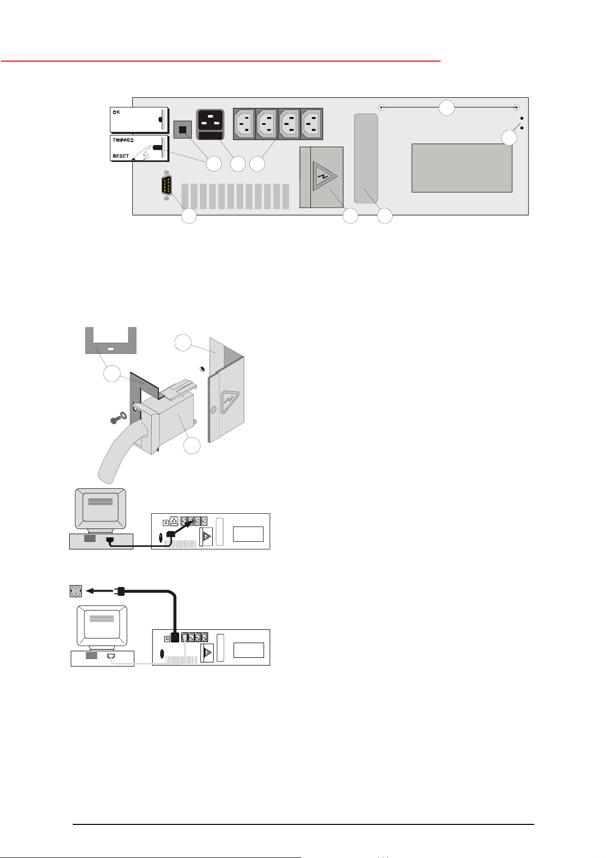
2.2 Installation Procedure
4
GE Digital Energy
A
B
51
6
1. Remove the transport screws (A, fig. 1) and store them in the free holes (B, fig.1). Mount the
NetPro 19”
it by using the front brackets only. The front brackets allow mounting of handles (not included).
2. Make sure that the air vents in the side panels of the module are not blocked by the mounting
rails or the side panels of the 19” rack.
7a
UPS in the 19” rack. The module must be supported by mounting rails, do not mount
1000VA model only:
3.
2
7
fig. 2
Battery extension module(s) can be installed to
increase the battery runtime. Connect the DC
connector of the battery module (7, fig. 2) to the DC
socket of the UPS (2, fig. 1/2). You will hear a click
when the cable is properly installed. Block the DC
connector: install the small locking plate (7a, fig. 2)
that came with the battery module, and fasten it with
the screw provided. Using the DC connector of the
battery module (not shown) you can install a second,
third, etc. module. See also section 5.1.
4. Switch off your computer, and unplug it from the
socket-outlet.
5. Disconnect the power cord from the computer
(rating 250Vac/10A) and connect this cord to the
mains input socket (5, fig. 1) of the UPS. See fig. 4.
2
3
fig. 1
6. Using the output cord(s) provided, connect the
computer(s) to the appliance outlet(s) (1, fig. 1) of
fig. 3
fig. 4
8. For best results, allow the UPS to recharge the batteries during a period of approx. 2 hours. It is
acceptable to use the UPS without first charging the battery, but the runtime may be reduced.
9. For advanced communication possibilities, the RS232 interface port (6, fig. 1) can be connected
to a computer system and/or optional interface cards (3, fig. 1) can be added. See chapter 4.
the UPS. Spread the loads over the appliance
outlets as equally as possible. If you use a
distribution box to connect more than one appliance
per outlet, please note that the maximum AC-current
rating of each appliance outlet is 10Amps. See fig. 3.
7. Connect the mains cord of the UPS to a working,
grounded AC wall socket outlet. See fig. 4. The
green LED 'on' (8, fig. 6) will blink now: mains power
is available and the batteries are charging. If the
LED does not blink but illuminates continuously
instead, press ‘0’ for one second.
OPM_NPE_19X_600_1K5_2GB_V030 3 GE DE NetPro 19” 600-1500: User manual 3.0 (GB)
Page 5
g
GE Digital Energy
3 - Operation
Please refer to figure 6.
3.1 Start-up
3.1.1 Start-up, mains available
1 Press keypad 'I' (14, fig. 6) briefly; LED ‘on’ (already blinking) will illuminate continuously now.
2 The equipment connected to the UPS can now be switched on.
3.1.2 Start-up, mains not available
If the mains input is absent (power cord not connected, or mains failure):
1 Press keypad 'I' until the buzzer sounds.
The LEDs 'on' and 'on battery' (13, fig. 6) will illuminate. The UPS operates on battery: it
discharges the batteries.
3.2 Use: Normal Operation
3.2.1 Normal operation conditions:
x
the mains supply is present,
x
the UPS is on,
x
the load does not exceed the capacity of the UPS and
x
the operating temperature is below alarm level
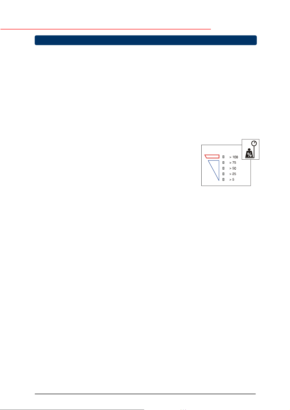
3.2.2 Load indication (fig. 5)
1 During normal operation, press keypad 'I' briefly.
2 Yellow LEDs will blink during 3 seconds, the number is load
dependent (in case of overload LED 'alarm' (9, fig. 6) blinks as well).
3.2.3 Auto-off (no-load shutdown)
If this function is activated, the UPS will switch off during a mains failure when the load is less
than 5% of the maximum load. In this way unnecessary discharging of the batteries is avoided.
The unit will automatically turn on again when mains power is restored. The default setting of the
no-load shutdown function is: activated. Changing of the setting is described in 3.4.
3.2.4 Automatic bypass switch
The UPS is equipped with an automatic bypass switch. This switch automatically transfers the
load to the mains if the UPS is unable to deliver the demanded output power due to overload or
overtemperature. The UPS will switch back to normal operation when the overload has been
removed or the temperature has dropped below alarm level.
If a power failure occurs during bypass operation, the UPS will switch to battery operation and
eventually, when the batteries are depleted, output power is lost. If the UPS functions under
overload or overtemperature conditions it may not be able to protect the load.
See also 3.3.6 and 3.4.
3.2.5 Switching off
1 Press keypad ‘0’ (15, fig. 6) for 1 second. If the UPS is switched off the output will always be
absent for a few seconds to ensure that the connected equipment is able to reboot.
2 If electric isolation is required, unplug the power cord from the wall outlet.
fig. 5
OPM_NPE_19X_600_1K5_2GB_V030 4 GE DE NetPro 19” 600-1500: User manual 3.0 (GB)
Page 6

g
3.3 Use: Status and Alarm Indications
status indications : the operating mode
o
low priority alarms : abnormal operating situations
!
GE Digital Energy
high priority alarms : situations in which
!!
output voltage of the UPS is no
longer guaranteed
action should be taken
on alarm
Situation
o Charger on
o Normal operation
(3.3.1)
(3.3.2)
- - - - -
the actual
; immediate
Indicators on front panel
on by-
pass
fig. 6
8
9
10
11 12 13 14 15
progr.
shutd.
repl.
batt.
on
batt.
buzzer*
! On battery
!! Battery low
!! On bypass
Bypass out of limits
!
(3.3.6)
!! Overload
!! High temperature
! Replace battery
o Progr. shutdown
pending
o Progr. shutdown in
progress
Operating modes and corresponding indications, see 3.3.1. – 3.3.10.
(3.3.3)
(3.3.4)
(3.3.5)
(3.3.7)
(3.3.10)
(3.3.10)
(3.3.8)
(3.3.9)
- - - - -
- - - - -
- - - - - - - - - -
- - - - -
- - - - -
- - - - -
- - - - -
1x/8 s.
- - - - -
1x/s.
- - - - -
1x/s.
- - - - -
1x/8s.
- - - - -
1x/s.
- - - - -
1x/s.
- - - - -
1x/8s.
- - - - = intermitting
= continuous
* = resettable: press push button ‘I’ > 2 secs.
OPM_NPE_19X_600_1K5_2GB_V030 5 GE DE NetPro 19” 600-1500: User manual 3.0 (GB)
Page 7

g
3.3.1 Charger on
The batteries are charging, see 2.2 step 7.
3.3.2 On line: normal operation
See 3.2.1.
3.3.3 On battery
The UPS uses the energy stored in the batteries: see chapter 7 ‘Batteries - runtime’.
The UPS will shutdown
x
after the batteries have been discharged (automatic restart), or
x
if keypad 'O' is pressed (restart via front panel required) or
x
if a 'UPS shutdown' command is given by the computer
(restart via front panel required).
Runtime indication (fig. 7)
During battery operation, press keypad 'I' briefly. The 4 yellow LEDs
indicate during 3 seconds the remaining runtime for the actual load.
GE Digital Energy
3.3.4 Battery low (end of runtime)
The batteries are nearly discharged: the remaining runtime is less than 2 minutes. Controlled
shutdown of any computer equipment is absolutely necessary at this point.
If the UPS operates at 100% load, the shutdown procedure should be completed within 2 minutes
after the 'battery low' alarm started. If only part of the output capacity of the UPS is used this
period can be longer, with aged batteries this period can be shorter.
When the batteries are fully discharged, the UPS is no longer able to power the connected
equipment.
3.3.5 On bypass
The bypass switch connected the load directly to the mains supply due to either overload or
overtemperature.
If keypad 'I' is momentarily pressed, the 4 yellow LEDs function during 3 seconds as a load
indication. See also 3.2.2. If 4 yellow LEDs
caused by an
bypass operation is caused by
temperature.
3.3.6 Bypass out of limits
The mains voltage or mains frequency are outside bypass input tolerance but inside UPS input
tolerance (see chapter 7). Bypass operation is inhibited: if for whatever reason the UPS is not
able to deliver the required output, output power is lost. If the input frequency is often out of
tolerance – during which bypass operation is inhibited and an alarm is generated – it may be
useful to disable the bypass function after which the unit operates as a UPS without automatic
bypass switch. See 3.4.
overload
. If only yellow LEDs illuminate (the red LED is off) during load indication,
overtemperature
fig. 7
and
the red LED illuminate, bypass operation is
. Take appropriate measures: reduce load and/or
3.3.7 Overload
The demanded power exceeds the normal capacity of the UPS. If keypad 'I' is momentarily
pressed to obtain a load indication all yellow LEDs will blink, and the red LED will remain blinking.
The alarm occurs when the load is > 100%. If the load exceeds 150% the UPS will immediately
switch to bypass, assuming that the conditions for a transfer to bypass are fulfilled.
If an overload condition between 110-150% persists, the UPS will eventually also switch to
bypass operation.
During an overload the UPS may automatically switch off within a few minutes (load dependent)
and output power is lost:
x
if a transfer to bypass is inhibited (see 3.3.6), or
x
if the bypass function has been disabled (see 3.4), or
x
if the UPS operates on battery (see 3.3.3).
To avoid these problems, be absolutely certain that the power demands of the protected
equipment are within the limits of the UPS.
OPM_NPE_19X_600_1K5_2GB_V030 6 GE DE NetPro 19” 600-1500: User manual 3.0 (GB)
Page 8

g
3.3.8 High temperature
The LED Indication is the same as during overload (see 3.3.7), but if keypad 'I' is momentarily
pressed to obtain a load indication the red LED will go out.
Overtemperature can be caused by:
x
extreme environmental temperature,
x
lack of proper ventilation,
x
overload situation.
Take appropriate measures; if the temperature is allowed to rise further the UPS will switch to
bypass operation (if allowed). If bypass operation is inhibited, the unit will switch off and output
power is lost.
3.3.9 Replace battery
Either the batteries are almost chemically worn out or the battery wiring, including the battery
fuse, is faulty. If the batteries are aged, they must be replaced as soon as possible to ensure full
protection for your equipment (see 6.2). Perhaps the 'replace battery' alarm occurs after a test
which you started immediately after installation or after a power failure. In this case the alarm may
be incorrect as the batteries have been (partly) discharged during transport or storage or during
the power failure. Allow the UPS to recharge the batteries. See also 3.5.
3.3.10 Programmed shutdown
The UPS monitoring software allows you to program a 'sleep period' of the UPS by sending two
commands to the UPS:
x
shut down after # minutes (blinking LED), and subsequently:
x
shut down during # hours (continuous LED).
During the 'sleep period' the UPS is not completely switched off as it has to keep track of the
remaining sleep time. However, if a mains failure occurs during the sleep period and the battery
capacity eventually drops below 80% of the normal capacity, the UPS will automatically switch off
in order to save battery power. When the mains returns the UPS will start up automatically. The
programmed sleep time however is lost.
The programmed shutdown in progress can be cancelled:
x
press keypad 'I' for at least 5 seconds to cancel shutdown and switch UPS on.
x
press keypad '0' for at least 5 seconds to cancel shutdown and switch UPS off.
GE Digital Energy
3.4 Use: Setup Mode
The setup mode can only be entered if the UPS is connected to a live wall outlet and switched
(LED 'on' blinks).
Press keypads 'O' and 'I' simultaneously. Press 'O' before 'I', otherwise the unit will be switched
on. Three yellow LEDs can illuminate:
LED is
LED indicating on* off
'on bypass' : the bypass switch is active not active
'progr. shutdown' : the no-load shutdown is active not active
'replace battery' : the output frequency is 50 Hz 60Hz
* = default
1 Scroll through the three functions with keypad 'I', the one selected blinks.
2 Toggle the setting of the selected function by pressing 'O' during approx 1 sec. (LED does not
blink anymore)
3 Store the new settings and leave the setup mode by pressing 'O' and 'I' simultaneously.
NOTE: The unit can be used as a frequency converter: the input frequency range is 45-66Hz, the
output frequency is selectable 50/60Hz. If the unit is used as a frequency converter, the
bypass function is no longer available. As a result an audible alarm will be generated
continuously (see 3.3.6). To avoid this, we advise to disable the bypass.
WARNING: Changing of the output frequency can cause severe damage of equipment
connected to the appliance outputs of the UPS: Be sure that the new frequency is
suitable for the connected equipment!
off
OPM_NPE_19X_600_1K5_2GB_V030 7 GE DE NetPro 19” 600-1500: User manual 3.0 (GB)
Page 9

g
3.5 Battery Management
Maximum battery life and reliability are obtained by the following features:
GE Digital Energy
xxxx
xxxx
xxxx
Quick battery test
The quick battery test checks whether the batteries and their wiring are healthy. If a quick battery
test shows that the batteries are close to being worn out, a 'replace battery' alarm will be
generated (see 3.3.9). The batteries must be replaced as soon as possible (see 6.2).
Automatic battery test
NetPro 19”
The
x
5 hours after manual switch-on
x
5 hours after return of mains following any power failure, and
x
30 days from the last battery test
Manual battery test
A quick battery test can be initiated manually through UPS software, via the RS232 Interface
Port. For details please refer to the manual of your monitoring software.
NOTE: If the test is started manually immediately after installation or after a power failure,
the UPS may generate a false 'replace battery' alarm as the batteries have been (partly)
discharged during transport/storage or during the power failure.
UPS conducts periodic automatic battery tests:
Deep battery test
A deep battery test, to be initiated through the UPS software via the RS232 port, checks the
actual battery capacity in order to ensure accurate runtime prediction. During a deep battery test
the batteries will be discharged until 'battery low' alarm level. Please note that immediately after a
deep battery test the expected runtime is very short: allow the UPS to recharge its batteries. For
details please refer to the manual of your UPS software.
Temperature compensated battery charging
This feature adjusts the battery charge voltage to the ambient temperature. As a result poor
charging of the batteries under low temperature conditions and overcharging of the batteries
under high temperature conditions are avoided.
xxxx
xxxx
xxxx
Load dependent battery-end-voltage
The allowable final battery voltage depends on the discharge current: the higher the current, the
lower the 'end-of-discharge' battery voltage. In this way maximum battery capacity is obtained
without overdischarging. Overdischarging would result in shortened service life and failure to
recover normal capacity.
Charger off at end of charge
Only charging when necessary, increases battery lifetime.
Automatic boost charge
This feature reduces the battery recharge time considerably: totally depleted batteries will be
recharged to 90% in approx. 1.5 hours, provided that discharging took place at 100% load.
OPM_NPE_19X_600_1K5_2GB_V030 8 GE DE NetPro 19” 600-1500: User manual 3.0 (GB)
Page 10

g
GE Digital Energy
4 - Communication
4.1 RS232 Port (fig. 8)
The RS 232 Port is a plug-in interface port (9-pin, Sub-D, male) which enables advanced communication
between the UPS and the computer (UPS software required). The interface port is operative as soon as
the mains power cord is plugged into a live wall outlet, even if the UPS is switched off.
We strongly recommend to use only original
the interface port.
Pin # Function
1 RS232 input (UPS shutdown)
2 RS232 output
3 General alarm
1)
4 Plug and Play
5 Common
6 Bypass active
7 Battery low
8 UPS connected
9 Mains failure
GE Digital Energy
fig. 8
software products in combination with
5 = COMMON
8 = UPS CONNECTED
MAINS FAILURE
DC
PnP
GENERAL ALARM
BATTERY LOW
BYPASS ACTIVE
RS232
5
9
4
8
3
7
2
6
1
DC
DC
1)
Active if the output voltage of the UPS is no longer
guaranteed due to other circumstances than already
indicated by pin 6-7-9:
-
Output converter overload
-
Overtemperature (pre-)alarm
-
High charger voltage
-
Bypass out of limits
-
Inverter shutdown (due to inverter failure or batt. failure)
DATA FROM
UPS
DATA TO UPS
REMOTE UPS
SHUT DOWN
MAX: +48V 100mA
4.2 Relay Interface Card (option)
The card is equipped with potential free change-over contacts for the following alarms:
• mains failure
• general alarm
• battery low
• bypass active
For more information please refer to the user manual that comes with the interface card.
4.3 SNMP Interface Card (option)
This card allows the data interface to be connected directly to an Ethernet network.
For more information please refer to the user manual that comes with the interface card.
RS232
RS232
RS232
PORT
OPM_NPE_19X_600_1K5_2GB_V030 9 GE DE NetPro 19” 600-1500: User manual 3.0 (GB)
Page 11

g
GE Digital Energy
5 - Optional Features
Apart from the options described in 4.2 and 4.3 the following options are possible:
5.1 Extended Runtime (NetPro 19” 1000)
Extended runtime can be obtained by connecting a separate battery extension pack to the UPS. In this
case the UPS must be informed about the new total battery capacity to allow a reliable recalculation of the
available runtime (please contact your dealer). Dependent of the charge condition of the new batteries the
new runtime calculations may temporarily be unreliable.
The additional batteries increase the recharging time for the unit, all other operational information is the
same as for standard models. It is not allowed to connect an external charger to the UPS!
5.2 PowerFLAG SerVICe Box for Modem Connection
If you connect the PowerFLAG SerVICe Box between the communication port of the UPS and a modem,
a programmed number can be dialed in case of a UPS alarm. It also allows service personnel to dial in
and check the status of the UPS to perform remote diagnostics. This way service costs, specially in
remote areas, can be reduced considerably.
6 - Maintenance
6.1 General
The UPS is virtually maintenance free: take care of proper environmental conditions and keep air
inlets/outlets free of dust. Please read 2.1.
6.2 Batteries
6.2.1 General
The service life of the battery is from 3 to 6 years, depending on the operating temperature and on the
number of discharge cycles.
As a healthy battery is critical to the performance of the UPS, an automatic quick battery test is performed
regularly to ensure failsafe operation (see section 3.5). When the condition of the battery is critical, a
'replace battery'
NOTE: under certain circumstances a
'quick battery test'.
6.2.2 Battery replacement
-
WARNING:
- When replacing the batteries, use the same number and voltage(V)/capacity(Ah).
- Proper disposal or recycling of the batteries is required. Refer to your local codes for disposal
requirements.
- Never dispose of batteries in a fire: they may explode.
- Do not open or mutilate batteries: their contents (electrolyte) may be extremely toxic. If exposed to
electrolyte, wash immediately with plenty of water.
- Avoid charging in a sealed container.
- Never short circuit batteries. When working with batteries, remove watches, rings or other metal
objects, and only use insulated tools.
alarm will be activated (see 3.3.9). Replace the batteries as soon as possible. See 6.6.2.
manual
first read the safety rules in section 1.2.
battery test can result in a false alarm: please see 3.5
Battery replacement procedure:
OPM_NPE_19X_600_1K5_2GB_V030 10 GE DE NetPro 19” 600-1500: User manual 3.0 (GB)
see next page
Page 12

g
Battery replacement procedure
GE Digital Energy
Refer to the label on the battery drawer.
1. Be sure that the transport screws (A, fig. 1) have
been removed.
2. Remove the front panel of the battery compartment.
Use a screw driver or pen as a lever.
3. Remove the two screws that hold the battery drawer.
4. Disconnect the DC connectors. Use a screwdriver
as a lever.
fig. 9
5. Remove battery drawer.
6. Remove clamp (two screws) and replace the
batteries.
7. Reinstall battery clamp, do not pinch or clamp the
wires.
8. Slide in the battery drawer.
9. Connect the DC connectors, a small spark is
normal. Fasten the two screws.
10. Reinstall the front panel.
Be careful, heavy weight!
OPM_NPE_19X_600_1K5_2GB_V030 11 GE DE NetPro 19” 600-1500: User manual 3.0 (GB)
Page 13

g
GE Digital Energy
7 - Troubleshooting
Whenever a malfunction occurs, first check external factors (e.g connections, temperature, humidity or
load) to determine whether the problem is caused by the unit itself or by its environment. Subsequently
check the thermal circuit breaker: it may be tripped. If so: reset it (see 4, fig.1) and be sure that the UPS is
not overloaded.
The following chart is a simple troubleshooting checklist only. If the suggested solution does not succeed,
or if the information is insufficient to solve the problem, please contact your dealer or consult
www.gedigitalenergy.com.
PROBLEM POSSIBLE CAUSE SOLUTION
Thermal Circuit Breaker (TCB)
tripped
UPS will not switch on (without
using 'battery start')
and the output has been off for
a few secs. (see also 3.2.5)
UPS will not switch on after
installation, LED 'on' remains off
UPS switched off automatically
UPS overload Reduce load, reset TCB
(4, fig. 1)
System failure Contact your dealer or consult
www. gedigitalenergy.com.
Most probably an overload See 3.3.7, reduce the loadLED 'on bypass' blinks
Overtemperature See 3.3.8
Allow the UPS to cool down
Line cord not connected Read 2.2
Connect line cord
Dead wall socket outlet, or
mains voltage out of limits
UPS overtemperature See 3.3.8
Tripped Thermal Circuit Breaker See above
Batteries have been discharged
too deep during transport and/or
storage
UPS overtemperature See 3.3.8
Mains failure, battery
discharged
Contact qualified electrician
Allow UPS to cool down
Contact your dealer or consult
www. gedigitalenergy.com
Allow UPS to cool down
Wait until mains returns
Programmed shutdown in
progress
UPS received shut down
command from computer during
mains failure
The load is < 5% of the max.
load and no mains power is
present.
(No-load shutdown function is
active, see 3.2.3)
LED ‘replace battery’
illuminates, buzzer is silent
OPM_NPE_19X_600_1K5_2GB_V030 12 GE DE NetPro 19” 600-1500: User manual 3.0 (GB)
Battery test just after installation
or mains failure
Battery test shows weak battery Read 6.2, replace batteries
See 3.3.10
Wait until mains returns
Wait until mains returns
Allow the UPS to recharge the
batteries
Page 14

g
GE Digital Energy
8 - Specifications
NetPro 19” model : 600 1000 1500
Ratings
Voltage Amperes (VA) : 600 1000 1500
with computer type load
Watts (W) : 360 600 900
with resistive load
Input thermal circuit breaker (A) : 5 5 7
Input fuse (A) : 8 8 10
Input converter
AC input voltage : 220 - 240 V
AC input voltage range : 100% load: 187 - 264 V
Minimum start-up AC voltage : 187 V (at any load)
Input current waveform : sinusoidal
Input current (A) at nom. inp. volt. : 2.0 3.3 5.0
Input power factor : 1
Input frequency range : 45 - 66 Hz
Inrush current : none
Output converter
AC output voltage : 230 V (suitable for 220 - 240 V loads)
AC output voltage tolerance : ± 2%
Output frequency : 50 or 60 Hz, front selectable
Output frequency range : nominal ± 0.15% unless synchronized to the mains
Output waveform : sine wave
Harmonic distortion : < 2% (typical 1.5%) with linear load
Power factor : 0.6 (0.7 at 90% load)
Crest factor (peak to RMS current) : suitable for loads with c.f. up to 6:1
Capacity appliance outlets : max. 10 A per outlet
Bypass
AC input voltage range : 195 - 264 V
Frequency tracking rate : 2 Hz/sec.
Frequency tracking range : nominal ± 10%
Phase difference : < 7º
Typical transfer time, msec : 4
Overload capability
Overload behaviour (battery operation) : 110% during 5 minutes; 150% during 5 seconds
Overload behaviour during : depends on rating of thermal circuit breaker
bypass operation typical: 125% of TCB value for 200 seconds
Batteries (ratings given for 25ºC)
Nominal voltage (Vdc) : 24 36 48
Number of 7 Ah batteries : 2 3 4
Type : sealed lead acid, maintenance free
Service life : up to 6 years (depending on use)
Recharge current : 1.5 A
Battery recharge time
(batt. discharged at 100% load) : 1.5 hours for 90% capacity, std battery
Runtime in minutes
at typical load (75%) : 12 12 10
VA/Watts
100/60 : 64 104 124
200/120 : 34 54 71
400/240 : 15 27 36
600/360 : 9 15 24
1000/600 : - 9 12
1500/900 : - - 6
General
Weight without battery drawer (kg) : 14 14 14
Weight with battery drawer (kg) : 19 22 24
Dimensions (hxwxd, mm) : 133.5 (3HU) x 450 (19”) x 440
Depth required in 19” rack (mm) : 420 (without connectors)
Enclosure / protection : steel - plastic / IP20
Environment
Safety : EN 50091-1-1, EN 60950, IEC 950
Electromagnetic compatibility : EN 50091-2
Ambient temperature : -10 to +40ºC
Audible noise at 1 meter : < 45 dB(A), load and temperature dependent
Max. relative humidity : 95% (non-condensing)
70% load: 120 - 264 V
input >264 Vac: UPS switches to battery operation
input >312 Vac: UPS shuts down, manual restart required
conform or better than EN 61000-3-2 (IEC 555-2)
: Fully protected against overload and short circuits
200% of TCB value for 10 seconds
300% of TCB value for 4 seconds
OPM_NPE_19X_600_1K5_2GB_V030 13 GE DE NetPro 19” 600-1500: User manual 3.0 (GB)
 Loading...