

Page 1
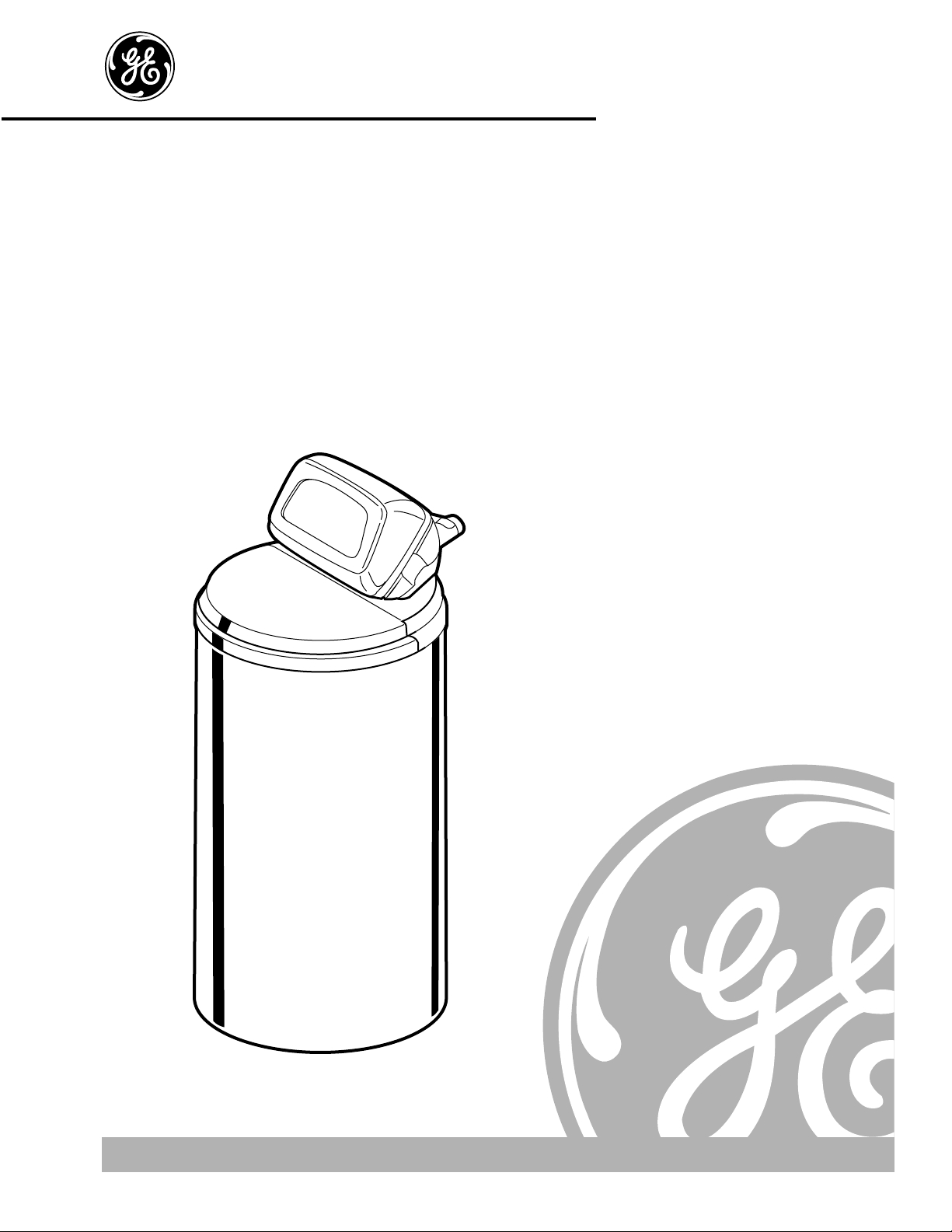
GXSS17Z01
GE Appliances
Water Softening System
Part No. 215C1044P003–1 Pub. No. 49-50007–1
8–98 CG
7196674
Installation and
Owner’s Manual
GE Answer Center ®800.626.2000
Page 2
Congratulations!
You are Now Part of the GE Family.
Safety Information
. . . . . . . . . . . . . 3
Installation Instructions
. . . .4–11
Important Recommendations . . . . . . . . . . . .4
Tools/Materials Required . . . . . . . . . . . . . . .5
Step-by-Step Instructions . . . . . . . . . . .7–11
Drain Connections . . . . . . . . . . . . . . . . . . .8
Sanitize . . . . . . . . . . . . . . . . . . . . . . . . . . .9
Program the Timer . . . . . . . . . . . . . . . . . .10
Specifications/Dimensions . . . . . . . . . . .11
Troubleshooting Tips
Before You Call For Service
. . . . . . . . . . . . .18
Operating Instructions
. . . .12–17
About the System . . . . . . . . . . . . . . . . . . .12
Service . . . . . . . . . . . . . . . . . . . . . . . . . . .12
Water Bypass . . . . . . . . . . . . . . . . . . . . .12
Breaking a Salt Bridge . . . . . . . . . . . . . .13
Cleaning the Nozzle
and Venturi Assembly . . . . . . . . . . . . . . .14
Features . . . . . . . . . . . . . . . . . . . . . . . . . .15
Regeneration . . . . . . . . . . . . . . . . . . . .16, 17
Customer Service
Product Registration . . . . . . . . . . . . . . .19, 20
Parts List . . . . . . . . . . . . . . . . . . . . . . .21–24
Warranty . . . . . . . . . . . . . . . . . . . . . . . . . .27
Service Telephone Numbers . . . . . . . . . . .28
2
Welcome to the GE family. We’re proud of our quality products and we are
committed to providing dependable service. You’ll see it in this easy-to-use Owner’s
Manual and you’ll hear it in the friendly voices of our customer service department.
Best of all, you’ll experience these values each time you use the water system. That’s
important, because your new system will be part of your family for many years. And
we hope you will be part of ours for a long time to come.
We thank you for buying GE. We appreciate your purchase, and hope you will
continue to rely on us whenever you need quality appliances for your home.
FOR YOUR RECORDS
Write the model and serial numbers here:
#
#
You can find them on the sump bracket.
Staple sales slip or cancelled check here.
Proof of the original purchase date is needed to obtain service under
the warranty.
Inside you will find many helpful hints on how to use and maintain
your water system properly. Just a little preventive care on your part
can save you a great deal of time and money over the life of your
system. A video has been included with the product containing
important use and care instructions.
You’ll find many answers to common problems in the
Before You Call
For Service
section. If you review our chart of
Troubleshooting Tips
first,
you may not need to call for service at all.
READ THIS MANUAL
IF YOU NEED SERVICE
If you do need service, you can relax knowing help is only a phone
call away. A list of toll-free customer service numbers is included in
the back section.
IMPORT ANT!
Fill out and return the Consumer Product Registration Card that is
packed with this product. If you cannot find it, please send in the
duplicate card printed in the back of this manual.
Customer Service Troubleshooting Tips
Installation Instructions
Safety Instructions
Operating Instructions
Customer Service Troubleshooting Tips Safety InstructionsCustomer Service Troubleshooting Tips Safety Instructions
Page 3
3
IMPORTANT SAFETY INFORMATION.
READ ALL INSTRUCTIONS BEFORE USING.
WARNING!
For your safety, the information in this manual must be followed to minimize the risk of
electric shock, property damage or personal injury.
Customer ServiceTroubleshooting Tips
Installation Instructions
Safety Instructions
Operating Instructions
SAFETY PRECAUTIONS
■ Check and comply with your state and local
codes. You must follow these guidelines.
■Use care when handling the water softening
system. Do not turn upside down, drop, drag,
or set on sharp protrusions.
■Water softening systems using sodium chloride
(salt) for regeneration add sodium to the water.
Persons on sodium restricted diets should consider
the added sodium as part of their overall intake.
Potassium chloride can be used as an alternative to
sodium chloride.
■
The water softening system works on 24 volt-60 Hz
electrical power only.
Be sure to use only the
included transformer.
■Keep the salt hole cover in place on the softener
unless servicing the unit or refilling with salt.
WARNING:
Do not
use with water that is
microbiologically unsafe or of unknown quality
without adequate disinfection before or after the
system.
Read and follow this Safety Information carefully.
SA VE THESE INSTRUCTIONS
PROPER INSTALLATION
■Install or store where it will not be exposed to
temperatures below freezing or exposed to any
type of weather. Water freezing in the system will
break it. Do not attempt to treat water over 100°F.
■
Do not
install in direct sunlight. Excessive sun heat
may cause distortion or other damage to nonmetallic parts.
■Properly ground to conform with all governing
codes and ordinances.
■Use only
lead-free solder and flux
for all sweatsolder connections, as required by state and
federal codes.
■
Maximum allowable inlet water pressure is 125 psi.
If daytime pressure is over 80 psi, nighttime
pressure may exceed the maximum. Use a pressure
reducing valve to reduce the flow if necessary.
WARNING:
Discard all unused parts and
packaging material after installation. Small parts
remaining after the installation could be a choke
hazard.
This water softening system must be properly installed and located in accordance with the Installation
Instructions before it is used.
Page 4
Read entire manual. Failure to follow all guidelines and rules could cause personal injury or property
damage.
•Before you begin installation, read these Installation Instructions completely. Then, obtain all the
materials and tools you will need to make the installation. Failure to properly install the softener
voids the warranty.
•Check local codes. The installation must conform to them.
•Use only lead-free solder and flux for all sweat-solder connections, as required by state and federal
codes.
•Connect the softener to the main water supply pipe
before
or
ahead of the
water heater.
DO NOT RUN
HOT WATER THROUGH THE SOFTENER.
Temperature of water passing through the softener must be
less than 120° F.
•Use care when handling the softener. Do not turn upside down, drop, drag, or set on sharp
protrusions.
•Maximum allowable inlet water pressure is 125 psi. If daytime pressure is over 80 psi, nighttime
pressure may exceed the maximum. Use a pressure reducing valve if necessary. (Adding a pressure
reducing valve may reduce the flow.)
•The softener works on 24 volt-60 Hz electrical power only. Be sure to use the included transformer.
Be sure the electric outlet and transformer are in an inside location to protect from wet weather.
•See
Where to Install the Softener
section for more details.
WARNING:
Do not use with water that is microbiologically unsafe or of unknown quality without
adequate disinfection before or after the system. The water should be tested periodically to
verify that the system is performing satisfactorily.
Small parts remaining after the installation could be a choke hazard. Discard safely.
4
Installation instructions.
Customer Service Troubleshooting Tips
Operating Instructions
Safety Instructions
Operating Instructions
Customer Service Troubleshooting Tips Safety Instructions
Operating Instructions
Customer Service Troubleshooting Tips Safety Instructions
Installation Instructions
CAUTION:
Certain plumbing skills are needed for installation. If you are unsure about any part
of the installation of this product, consult a professional plumber.
Unpacking and Inspection
The softener is shipped in one master carton. The softener is completely assembled at the factory,
except as required at installation.
Be sure to check the entire softener for any shipping damage or parts loss. Also note damage to the
shipping cartons. Contact the transportation company for all damage and loss claims. The
manufacturer is not responsible for damages in transit.
Small parts, needed to install the softener, are on a skin-packed cardboard piece. To avoid loss of the
small parts, keep them on the skin-pack until you are ready to use them.
Important Installation Recommendations
Page 5
5
Customer ServiceTroubleshooting Tips
Installation Instructions
Safety Instructions
Operating Instructions
•Place the softener as close as possible to a sewer drain, or other acceptable drain point or standpipe.
•It is recommended to keep outside faucets on hard water to save soft water and salt.
•Do not install the softener in a place where it could freeze.
Freeze damage is not covered by the warranty.
•Do not install the softener where it would block access to the water heater or access to the main water
shutoff.
•Put the softener in a place where water damage is least likely to occur if a leak develops. The
manufacturer will not repair or pay for water damage.
•A 120 volt electric outlet is needed to plug in the included transformer. The softener has a 10 foot
power cable. If the outlet is remote (up to 100 feet), use 18 gauge wire to connect.
Be sure the
electric outlet and transformer are in an inside location, to protect from wet weather.
Be sure the outlet
is unswitched to prevent accidental shutoff.
•If installing in an outside location, you must take the steps necessary to assure the softener,
installation plumbing, wiring, etc., are as well protected from the elements (sunlight, rain, wind,
heat, cold), contamination, vandalism, etc., as when installed indoors.
•
Keep the softener out of direct sunlight.
The sun’s heat may distort non-metallic parts and may damage
the electronics.
Where to Install the Softener
•In and out pipes to the softener must be at least 3/4″size. Some local codes require a minimum of
1″pipe size. To plumb with 1″pipes, buy adapters to fit the 1″pipe threads on the bypass valve (see
Fig. 1 and Fig. 2).
• Use copper, brass or galvanized pipe and fittings. Some codes may also allow CPVC plastic pipes.
• Use the included bypass valve to install the softener. The bypass valve allows you to turn off water to
the softener for servicing, but still have water in the house pipes.
• Drain hose is needed for valve and salt tank drains. A 20′length of drain tubing is included. If a
longer length is needed, it can be ordered from GE Parts at 800.626.2002.
• If a rigid valve drain is needed to comply with plumbing codes, you can buy the parts needed (Fig. 4A)
to connect a 1/2″copper tubing or plastic pipe drain.
• Clean nugget or pellet water softener salt is needed to fill the brine tank, see
Step 9.
in the
Step-by-
Step Installation Instructions.
Tools and Materials Required for Installation
You must first decide how to run in and out pipes to the softener. Look at the house main water pipe
at the point where you will connect the softener. Is the pipe soldered copper, glued plastic, or
threaded galvanized? What is the pipe size?
WARNING:
Use only lead-free solder and flux to prevent lead poisoning.
See
T ypical Installation Illustration,
Fig.1. Use this as a guide when planning your particular installation.
Be sure to direct the incoming hard water supply to the softener valve inlet fitting.
The valve
is marked INand
OUT.
See below to help you prepare.
NOTE:
The state of Massachusetts requires a licensed plumber to perform the installation.
Plan How You Will Install the Softener
Page 6
Installation instructions.
Customer Service Troubleshooting Tips
Installation Instructions
Safety InstructionsCustomer Service Troubleshooting Tips
Operating Instructions
Safety InstructionsCustomer Service Troubleshooting Tips Safety Instructions
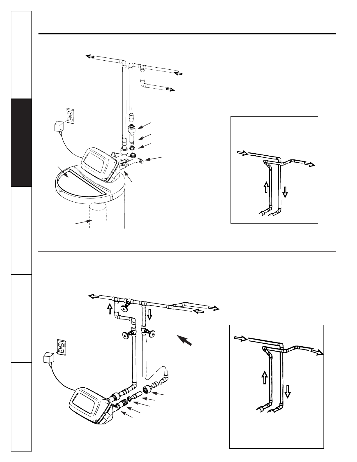
Typical Installation Illustration
Fig 1.
Optional 3-Valve Bypass Installation Illustration
Fig 2.
6
Adapters for this installation are not supplied with the softener. To order these adapters, call
GE Parts 800.626.2000.
Soft water
Hard water to
outside faucets
MAIN WATER PIPE
Hard water
Installation nut (2)
Copper tube, 3/4″(2)
Washer (2)
Bypass Valve
• Pull out for service
• Push in for bypass
NOTE:
Threads on the bypass
valve are 1″ male pipe. If 1″
pipes are needed, do not use the
copper tubes and nuts included.
Buy adapters and plumb directly
to the 1″ threads.
INLET
Brinewell
NOTE:
See
Drain Hose
Connections
section.
SALT
GOES HERE
Salt hole
cover
removed
24V transformer
120-volt outlet
Hard water
Soft water
From softener outlet
To softener inlet
CROSS-OVER
Use if water supply flows from the left.
Include single or 3-valve bypass.
Hard water
Soft water
From softener outlet
To softener inlet
CROSS-OVER
Use if water supply flows from the left.
Include single or 3-valve bypass.
MAIN WATER PIPE
Soft water
Hard water
Copper tube, 3/4″ (2)
Washer (2)
Installation adapter (2)
INLET
NOTE:
Threads on the installation adapters are 1″ male pipe.
If 1″ pipes are needed, do not use the copper tubes and nuts
included. Buy adapters and plumb directly to the 1″ threads.
24V transformer
120-volt outlet
Bypass valve
Hard water to outside faucets
Inlet valve
Outlet valve
Nut (2)
3-valve bypass system
For soft water service:
• Open the inlet and outlet valves
• Close the bypass valve
For bypass hard water:
• Close the inlet and outlet valves
• Open the bypass valve
Page 7
Step-by-step installation instructions.
Customer ServiceTroubleshooting Tips
Installation Instructions
Safety Instructions
Operating Instructions
7
Turn off the water supply to pipes to be cut and drain the
house water pipes. Open both hot and cold faucets.
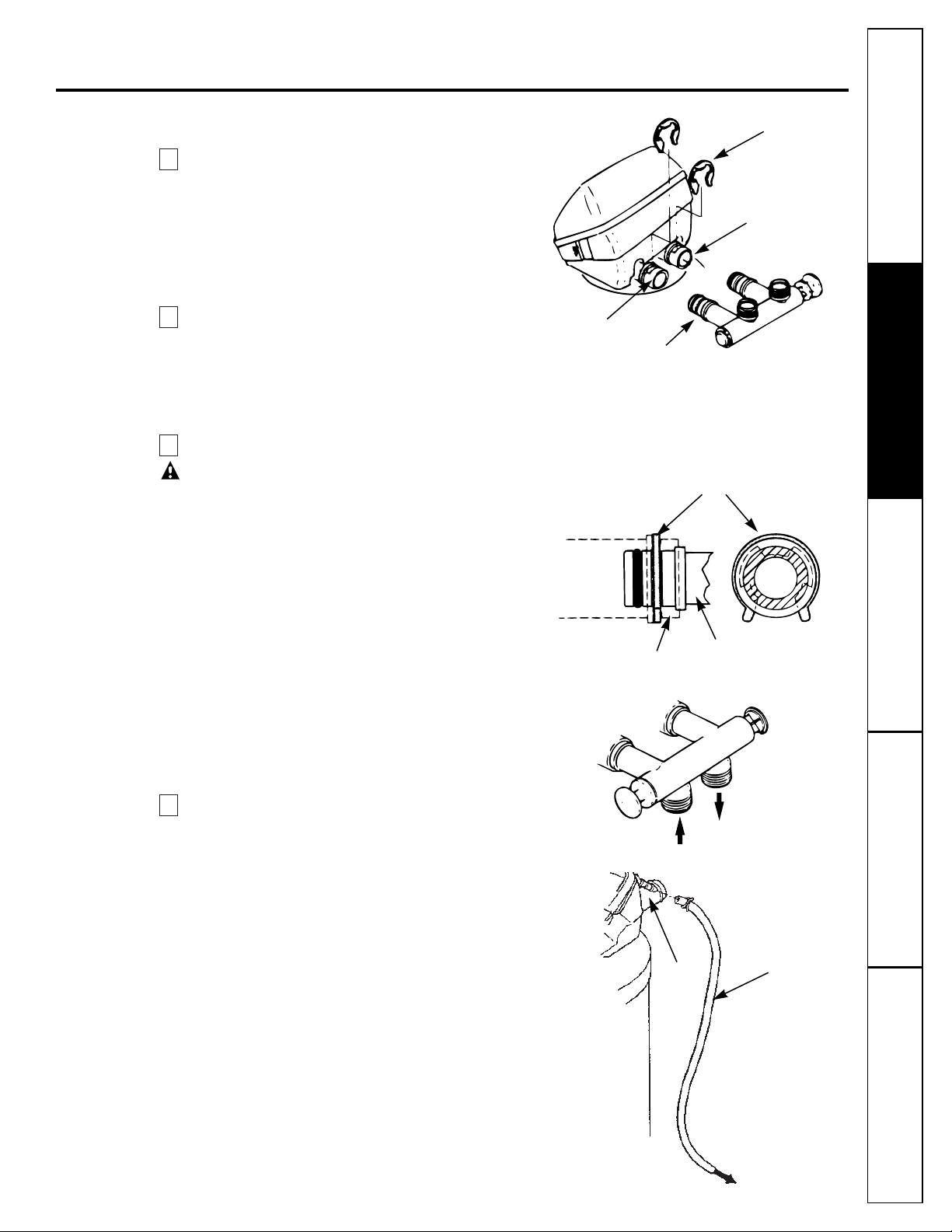
Install bypass valve:
•Push the bypass valve (lubricate o-ring seals with silicone
grease) into both ports of the valve as shown in Fig. 3A.
•Snap the 2 large plastic clips in place, from the top, down
as shown in Fig. 3A and Fig. 3B. Be sure they snap into
place. Pull on the bypass valve to make sure it is held
securely in place.
Move the softener assembly into installation position:
•Be sure the installation surface is level and smooth. Sharp
objects under the tank may puncture it. If needed, place
the tank on a section of 3/4″thick (minimum) plywood.
Then, place shims under the plywood as needed to level
the softener.
Plumb IN and OUT pipes to and from softener:
CAUTION:
Observe all of the following cautions as you
connect inlet and outlet plumbing.
•Turn off the water heater.
•Be sure incoming hard water supply is directed to the
softener valve inlet port. If house water flow is from the
left, use a plumbing cross-over as shown in Fig. 1.
•If making a soldered copper installation,
do all sweat
soldering before
connecting pipes to the bypass valve.
Torch
heat will damage plastic parts.
•When turning threaded pipe fittings onto plastic fittings,
use care not to cross-thread.
•Use pipe joint compound on all external pipe threads.
•Support inlet and outlet plumbing in some manner (use
pipe hangers) to keep the weight off of the valve fittings.
Install the brine tank overflow fittings:
•Insert the rubber grommet into the 3/4″diameter hole in
the brine tank sidewall as shown in Fig. 5.
•Push the end of the hose adapter elbow into the grommet
as shown in Fig. 5.
4
3
2
1
Fig. 3A.
Fig. 3B.
Fig. 3C.
Fig. 4.
Drain
fitting on
valve
Valve
drain
hose
To sewer drain
IN
OUT
Turn bypass valve upside down to connect
to floor level plumbing
Valve body inlet or
outlet
Bypass valve
(push all the way in)
Clip
END
VIEW
Clip
Outlet
Inlet
O-ring seal goes into the outer groove
only. The clip snaps into the inner
groove (see below).
Bypass valve
NOTE:
Threads on
the valve are 1″
male pipe. If 1″
pipe is needed, buy
adapters and plumb
to the 1″ threads.
SIDE
VIEW
Page 8
Step-by-step installation instructions.
Customer Service Troubleshooting Tips
Installation Instructions
Safety InstructionsCustomer Service Troubleshooting Tips
Operating Instructions
Safety InstructionsCustomer Service Troubleshooting Tips Safety Instructions
Connect and run the valve drain hose:
•Use the provided drain hose (20′length included) to attach
to the valve drain fitting. To keep water pressure from
blowing the hose off, use a hose clamp to secure in place.
•Locate the other end of the hose at a suitable drain point
(floor drain, sump, laundry tub, etc.) that terminates at the
sewer.
Check and comply with local codes.
IMPORTANT:
If more drain hose is needed, it should be
ordered from GE Parts at 800.626.2002.
The water softener will
not work if water cannot exit this hose during regenerations.
•Tie or wire the hose in place at the drain point. High water
pressure will cause it to whip during the back-wash and fast
rinse cycles of regeneration.
Also provide an air gap of at least
1–1/2″between the end of the hose and the drain point.
An air
gap prevents possible siphoning of sewer water into the
softener, if the sewer should back-up.
•If raising the drain hose overhead is required to get to the
drain point,
do not raise higher than 8´above the floor.
Elevating the hose may cause a back-pressure that could
reduce brine draw during regenerations.
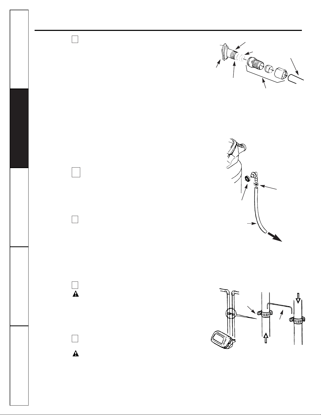
Connect a rigid valve drain tube:
•To adapt a copper drain tube to the softener, use a hacksaw to
cut the barbed end from the drain fitting as shown in Fig. 4A.
Rotate the drain fitting so the cutting blade clears the valve
housing to prevent damage to valve. Buy a compression fitting
(1/4″female pipe thread x 1/2″O.D. tube) and needed
tubing from your local hardware store.
Connect and run the cabinet (brine tank) overflow hose
•
Attach a length of hose (use remaining hose from
Step 5
) to
the drain elbow installed in
Step 4.
Use a hose clamp to hold
it in place.
•
Locate the other end of the hose at the drain point.
DO NOT
ELEVATE
this hose higher than the elbow on the brine tank.
DO NOTTEE
this hose to the valve drain hose.
NOTE:
This drain is for safety only. If the cabinet (brine tank)
should over-fill with water, the excess is carried to the drain.
Install grounding clamps and wire:
DANGER:
Failure to properly attach ground wire could
result in electrical shock.
•If plumbing is metal, to
maintain electrical ground continuity
in the house cold water piping, install the included ground
clamps as shown in Fig. 6. Be sure the pipes are clean under
the clamps to assure good contact.
Flush pipes, expel air from softener, and test your
installation for water leaks:
CAUTION: To avoid water or air pressure damage to softener
inner parts, be sure to do the following steps in exact order.
A.
Fully open 2 cold soft water faucets nearby the softener.
B.
Place bypass valve in bypass position by pushing the stem
inward.
C.
Fully open the house main water pipe shutoff valve. Observe
a steady flow from both faucets opened in
Step A
above.
8
7
6
5A
5
8
Fig. 4A
Fig. 5
Fig. 6
Clamp (2)
Ground
wire
From valve outlet
To valve
inlet
To sewer
drain
Overflow drain hose
Hose clamp
Grommet
Clip
1/4″ NPT threads
Barbs
1/2″ O.D. copper
tube (not furnished)
Cut barbs
from drain
fitting
Compression fitting,
1/4″ NPT X 1/2″O.D.
tube (not furnished)
Page 9
Add water and salt to the brine tank:
•Remove the cabinet (brine tank) cover. Add about 3 gallons of water into the tank. Do not add
into the brinewell.
•Fill tank with
NUGGET, PELLET
or coarse
SOLAR
water softener salt with a purity of 99.5% or higher.
Do not use rock, block, granulated, or ice cream-making salts. Salt storage capacity is
approximately 200 lbs. for model GXSS17. Keep the salt hole cover in place on the softener
unless servicing the unit or refilling with salt.
NOTE:
If the softener is installed in a humid basement or other damp area, it is better to fill the tank
with less salt, more frequently. Eighty to 100 lbs. of salt will last for several months, depending on
water hardness and family size.
Connect to electrical power:
•If transformer wiring is not visible at the back of the control head, remove control cover.
DO NOT
PULL ON OR DISCONNECT WIRING.
Locate the long wire with U shaped connectors on one end.
Route this wire through the rear of the control housing. Replace the control cover.
•Fasten the 2 power cable lugs (U shaped connectors) to the 2 screws on the transformer, and
tighten the screws. Then, plug the transformer into the electrical outlet.
Program the CONTROL.
11
10
9
Customer ServiceTroubleshooting Tips
Installation Instructions
Safety Instructions
Operating Instructions
9
D.
Place bypass valve in the service position
EXACTLY
as follows.
KEEP SOFT WATER FAUCETS OPEN.
SLOWLY
pull or slide the valve stem toward service, pausing several times to allow the softener to
pressurize slowly. This initial flow of water may be rusty colored. This is normal and will disappear
quickly.
E.
After about 3 minutes, open a
HOT
water faucet for 1 minute, or until all air is expelled, then close.
F.
Close all water faucets.
G.
Check your plumbing work for leaks and fix right away if any are found. Be sure to observe
previous caution notes.
H.
Turn on the gas or electric supply to the water heater. Light the pilot, if applicable.
I.
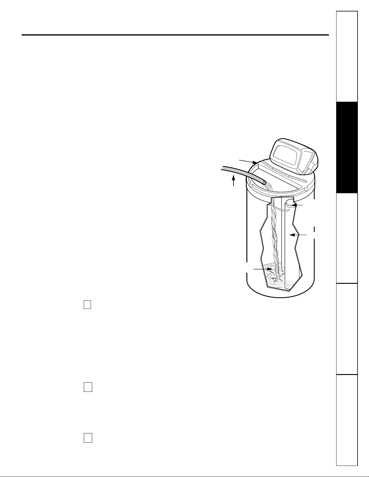
Sanitize the softener.
Care is taken at the factory to keep your softener clean
and sanitary. Materials used to make the softener will
not infect or contaminate your water supply and will
not cause bacteria to form or grow. However, during
shipping, storage, installing and operating, bacteria
could get into the softener. For is reason, sanitizing
as follows is suggested when installing.
•Lift the salt hole cover and use a pail or hose to
fill the salt storage tank with at least 3 gallons
of water.
•
Remove the brinewell cover, see Fig. 7 and pour
about 3/4 ounce of common 5.25% household
bleach (Clorox, Linco, BoPeep, White Sail, Eagle,
etc.) in the softener brinewell.
•Press the
TOUCH/HOLD
button and hold for 3
seconds to start a recharge. This first recharge
does
several things: fills the salt tank to the water
level needed,
gets all the air out of the resin tank,
makes the resin bed ready for service. See the
Recharging
section.
NOTE: This recharge takes about 2 hours.
Fig. 7
Salt hole cover
removed
Hose
Brinewell
Brinewell
cover (remove
and add about
3/4 oz. bleach)
Water, about
3 gallons
Page 10

Step-by-step installation instructions.
Customer Service Troubleshooting Tips
Installation Instructions
Safety InstructionsCustomer Service Troubleshooting Tips
Operating Instructions
Safety InstructionsCustomer Service Troubleshooting Tips Safety Instructions
10
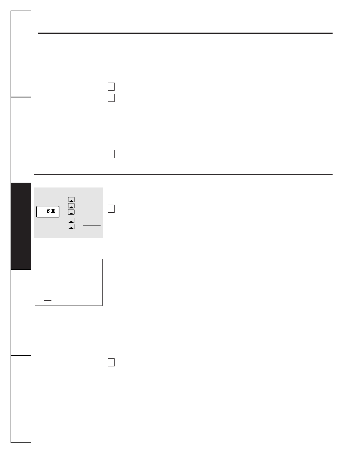
Program the Timer
Set the timer:
When the transformer is plugged into electrical outlet, 12:00AM, SUnday will begin to flash in the time display.
Set the time of day and present day of week as follows:
A.
Set the time of day:
Press the
TIME/DAY
b
utton once and the hour display will begin to flash.
Press the
SET/CLEAR
b
utton until the present hour of the day shows in the display. Be sure AMfor
morning hours, or PMfor afternoon and evening hours shows.
NOTE:
Press
SET/CLEAR
button and quickly release to move the hour display ahead 1 at a time to the
correct hour. Or, hold the
SET/CLEAR
button to move the display ahead 2 hours each second, to the
correct hour.
Press the
TIME/DAY
b
utton once to steady the hour display, and minutes begin to flash.
Repeat
Step A. 2
to set the correct minutes.
Press the
TIME/DAY
b
utton again to steady the minute display (day will begin flashing). Fig. 9 shows
the timer set at 3:30 PM.
B.
Set the present day of the week:
Press the
SET/CLEAR
b
utton to set the present day of the week in the display.
NOTE:
Press
SET/CLEAR
b
utton and quickly release to move the day display 1 at a time. Or hold the
SET/CLEAR
button to move the day display ahead 2 days each second.
Press the
TIME/DAY
button again to steady the entire display. Fig. 9 shows the timer set at
TUesday.
No other settings are needed
after installing your water softener. The softener is factory set to regenerate every
Monday, Wednesday and Saturday (beginning at 2:00 AM). For most families, this gives enough soft water
for their needs. However, if you want the softener to regenerate at a different time, or on different days, or to
set for the most efficiency, see
About the Water Softener System
section.
2
1
4
3
2
1
Solid State Timer
SmartWater Softening System
REGENERATE NOW
VACATION ON/OFF
TOUCH
HOLD
SET/CLEAR
TIME/DAY
REGENERATION
DAY
REGENERATION
TIME
Fig. 8
See the
Operating
section for other timer controls and features.
REGENERATE NOW
VACATION ON/OFF
TOUCH
HOLD
SET/CLEAR
TIME/DAY
REGENERATION
DAY
REGENERATION
TIME
PM
TU
E
E
Fig. 9
EXAMPLE: This drawing shows the
present time of day at 3:30 PM,
and the present day on TUesday.
Page 11

Customer ServiceTroubleshooting Tips
Installation Instructions
Safety Instructions
Operating Instructions
11
Specifications/Dimensions
Rated Capacity
Amount of high capacity resin (lbs/cu. ft)
Resin tank nominal size (in., dia. x height)
Service flow rate (gpm)
Water supply maximum hardness (gpg)
➄
Water supply maximum clear water iron (ppm) ➄
Water pressure limits (min.-max. psi)
Pressure drop at rated service flow (psig)
Water temperature maximum (°F)
Water supply minimum flow rate (gpm)
Regeneration cycle flow rates (gpm)
Fill (flow to brine tank)
Brining
Brine Rinse
Backwash
Fast Rinse
GXSS17Z
31.2/.6
8 x 40
8
50
3
20-125
15
120
3
.3
.19
.12
1.8
1.8
See rating decal, located on
the Softener
➄Determined by water analysis from a qualified water testing laboratory.
}
(flow to drain)
GXSS17
11–1/2″
3–3/8″
OUT
INLET
INLET-OUTLET
48–3/4″
41–1/4″
18–1/4″
40–1/2″
Page 12

Service
When the
water softening system
is providing soft water, it is called “Service.” During
service, hard water flows from the house main water pipe into the
water softening system
.
Inside the
water softening system
resin tank is a bed made up of thousands of tiny, plastic
resin beads. As hard water passes through the bed, each bead attracts and holds the hard
minerals. This is called ion-exchanging. It is much like a magnet attracting and holding
metals. Water without hard minerals (soft water) flows from the
water softening system
and
to the house pipes.
After a period of time, the resin beads become coated with hard minerals and they have to
be cleaned. This cleaning is called regeneration, or recharge. Regeneration is started at
2:00 AM (factory setting) by the
water softening system
control, and consists of five stages or
cycles. These are
FILL, BRINING, BRINE RINSE, BACKWASH
and
FASTRINSE
.
About the water softener system.
Customer Service Troubleshooting Tips
Installation Instructions
Safety InstructionsCustomer Service Troubleshooting Tips
Operating Instructions
Safety InstructionsCustomer Service Troubleshooting Tips Safety Instructions
12
Automatic Hard Water Bypass During Regeneration
For emergency needs, hard water is available
to the home during the regeneration cycles.
However, you should avoid using HOT water
because the water heater will fill with the
hard water.
Fill Backwash
Salt dissolved in water is called brine. Brine
is needed to clean the hard minerals from
resin beads. To make the brine, water flows
into the salt storage area during the fill stage
as shown.
Brining
During brining, brine travels from the salt
storage area into the resin tank. Brine is the
cleaning agent needed to remove hard
minerals from the resin beads. The hard
minerals and brine are discharged to the
drain.
The nozzle and venturi create a suction to
move the brine, maintaining a very slow rate
to get the best resin cleaning with the least
salt.
Brine Rinse
After a pre-measured amount of brine is
used, the brine valve closes. Water
continues to flow in the same path as during
brining, except for the discontinued brine
flow. Hard minerals and brine flush from
the resin tank to the drain.
During backwash, water travels upthrough
the resin tank at a fast flow rate, flushing
accumulated iron, dirt, and sediments from
the resin bed and to drain.
Fast Rinse
Backwash is followed by a fast flow of water
down
through the resin tank. The fast flow
flushes brine from the bottom of tank, and
packs the resin bed.
After fast rinse, the
water softening system
returns to soft water service.
Soft water
OUT
Salt storage
tank (salt
not shown)
Brine
valve
Hard water
IN
Resin
tank
Resin
bed
Soft water
OUT
Hard water
IN
Salt
storage
tank
Fill
water
Brine
valve
Hard water
bypass OUT
Nozzle &
venturi
Hard water
IN
Brine
valve
Brine
Drain
Drain
Hard water
bypass OUT
Hard water
IN
Drain
Soft water
OUT
Hard water
IN
Page 13

Customer ServiceTroubleshooting Tips
Installation Instructions
Safety Instructions
Operating Instructions
13
Breaking a Salt Bridge
Sometimes, a hard crust or salt bridge forms in the salt storage area. It is usually caused
by high humidity or the wrong kind of salt. When the salt bridges, an empty space forms
between the water and salt. Then salt will not dissolve in the water to make brine.
If the brine tank is full of salt, it is hard to tell if you have a salt bridge. Salt is loose on top,
but the bridge is under it. The following is the best way to check for a salt bridge.
Salt should be loose all the way to the bottom of the tank. Take a broom handle or like
tool, and carefully push it down into the salt, working it up and down. If the tool strikes a
hard object (be sure it’s not the bottom or sides of the tank), it’s most likely a salt bridge.
Carefully break the bridge with the tool.
Do not
pound on the walls of the tank.
If the wrong kind of salt made the bridge, take it out. Then fill the tank with nugget or
pellet salt only. In humid areas, it is best to fill with less salt, more often.
Push tool into salt
bridge to break
Pencil
mark
Broom
handle
Salt
Salt
bridge
Water level
1
² – 2²
Page 14
About the water softener system.
Customer Service Troubleshooting Tips
Installation Instructions
Safety InstructionsCustomer Service Troubleshooting Tips
Operating Instructions
Safety InstructionsCustomer Service Troubleshooting Tips Safety Instructions
14
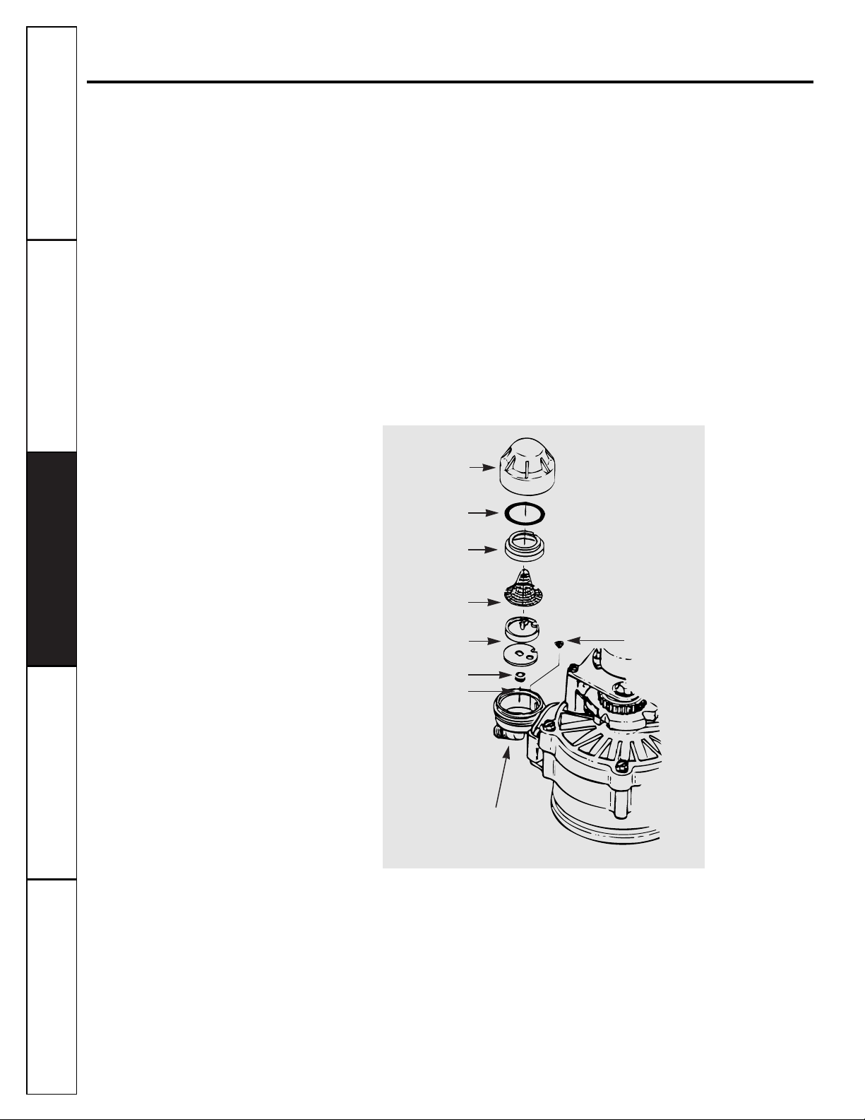
Cleaning the Nozzle and Venturi Assembly
A clean nozzle and venturi is needed for the water softening system to work properly.
This small
unit makes the suction to move brine from the salt storage area to the resin tank during
regeneration. If it becomes plugged with sand, dirt, etc., the water softening system will not
work and you will get hard water.
To get to the nozzle and venturi, remove the water softening system top cover. Be sure the
water softening system is in service cycle (no water pressure at nozzle and venturi). Then,
while holding the nozzle and venturi housing with one hand, remove the cap. Lift out the
screen support and screen, then the nozzle and venturi. Wash and rinse the parts in warm
water until clean. If needed, use a small brush to remove iron or dirt. Also check and clean
the gasket.
NOTE:
Some models have a small flow plug located in the nozzle and venturi, and/or a
small cone shaped screen in the housing. Be sure to check and clean these parts, if your
model is so equipped.
Carefully replace all parts in the correct order. Lightly lubricate the o-ring seal with clean
silicone grease or petroleum jelly and place in position.
Install and tighten the cap, by hand
only. Do not over-tighten the cap or housing.
IMPORTANT: Be sure small holes in the gasket are centered directly
over the small holes in the nozzle and venturi housing.
*Install with numbered side up, concave side down.
Cap
O-ring seal
Screen support
Screen
Screen
Nozzle & Venturi
Nozzle & Venturi housing
Gasket
*Fill Flow plug
Page 15

If electrical power to the timer goes off, the
memory built into the timer circuitry keeps
all settings for six hours (minimum) or
more. The display is blank and softener will
not regenerate.
When electrical power comes on… one of two
things will happen.
The present time of day will show,
meaning the timer memory has kept all
settings.
NOTE:
If the softener was in a
regeneration when the power was lost, it
will now finish the cycle.
OR
The display will show a flashing time.
The timer memory did not keep the
time settings and they must be reset.
See the
Program the Timer
section.
NOTE:
When the power comes on, the
flashing display returns to a time of
12:00 AM Sunday, then begins to keep
time again. If you do not reset all time
settings, the softener will regenerate
three days each week. However,
regeneration will most likely be on the
wrong days and at the wrong time.
If the softener was in a regeneration when
the power went off, the valve will return to
service position without finishing the
regeneration cycle.
If your water tastes salty:
—use
RECHARGENOW
to start another
regeneration. See the
Recharging
section.
—open one or more soft water faucets and
allow to run until the salt taste is gone.
2
1
About the face plate timer features.
Customer ServiceTroubleshooting Tips
Installation Instructions
Safety Instructions
Operating Instructions
15
Recharging
If you have guests visiting, or other times when you use more water than usual, you could
begin to run out of soft water. If the softener is not scheduled to regenerate for another day
or two, you would get hard water until then. If this happens, or you think it might happen,
press and hold in the
TOUCH HOLD
button for three seconds until
RCHG
shows.
RCHG
will
flash in the display during the regeneration, which lasts under two hours.
NOTE:
Avoid using
HOT
water while the softener regenerates, because bypass hard water will
refill the water heater, see the
Automatic Bypass
section.
REGENERATE NOW
VACATION ON/OFF
TOUCH
HOLD
SET/CLEAR
TIME/DAY
REGENERATION
DAY
REGENERATION
TIME
PM
RCHG
Going on Vacation?
The day you leave on vacation, or for a long
absence, press (do not hold) the
TOUCH
HOLD
button
VAC
begins to flash in the
display. The timer will keep time, but the
softener will not regenerate.
NOTE:
While on vacation, the softener will
go through a regeneration if the
RECHARGE
NOW
feature is used.
To shut off the water supply to the softener,
use the plumbing bypass valve.
When you return, press the
VACATION
button again to return the softener to
service and also returning the softener to
the correct time of day in the display.
WARNING:
Remember to do this or the
softener will not regenerate and you will
soon have hard water.
Error Code
An error code could appear in the face plate display if a problem occurs in the softener
electronics. If you see an error code instead of the present time of day, see the
Trouble
ShootingTips
section or call the GE Answer Center 800.626.2000 for service.
What to do When a Power Outage Occurs.
TIME/DAY
REGENERATION
PM
RCHG
TIME
REGENERATION
DAY
SET/CLEAR
TOUCH
HOLD
VACATION ON/OFF
REGENERATE NOW
E
E
Page 16
It is not hard to fine-tune your softener, but it does take a few minutes of your time to do it right.
Read the following carefully.
To have soft water all the time, the softener must regenerate, or recharge a certain number of
times in each seven day period. How many times to regenerate (set the timer) depends on three
things:
The number of people in your home tells you how much water is used.
The grains per gallon (GPG) hardness of your water supply.
NOTE:
If your water supply contains iron, compensate for it by adding to the water hardness
number.
For example, assume your water is 15 gpg hard and contains 2 ppm iron. Add 5 to
the
hardness number for each 1 ppm of iron thus, making the example water hardness number 25 .
15 gpg hardness
2 ppm iron x 5 = 10 +10
(times) 25 HARDNESS NUMBER
How much salt used in each regeneration is determined by the length of the fill cycle. See
the
Regeneration Chart
section.
3
2
1
About regenerating the system.
Customer Service Troubleshooting Tips
Installation Instructions
Safety InstructionsCustomer Service Troubleshooting Tips
Operating Instructions
Safety InstructionsCustomer Service Troubleshooting Tips Safety Instructions
16
Setting the Timer for Days and Fill Minutes of Regeneration
NOTE:
The timer is factory set for Monday, Wednesday and Saturday with regenerations starting
at 2:00 AM. Fill time is factory set for 16 minutes.
Set days and time of regeneration or recharge.
Step 1—
Press the
REGENERATION TIME
button once to display the factory set regeneration days
and starting time (flashing). To change the regeneration start time, do
Step 2
following
this. Otherwise go to
Step 3.
NOTE:
See
Automatic Bypass
section, when choosing a regeneration starting time other
than 2:00 AM.
Step 2—
Press the
SET/CLEAR
button until the desired regeneration starting time shows in the
display.
NOTE:
Press
SET/CLEAR
and quickly release to move the display ahead 1 hour at a
time.
Or, hold the
SET/CLEAR
button to move display ahead 2 hours each
second.
Step 3—
Press the
REGENERATION DAY
button and
SUnday
begins to flash.
—
If you do want regenerations on Sunday, see the
Regeneration Chart
, press the
SET/CLEAR
button to display
ON.
—
If you do
NOT
want regenerations on Sunday, press
SET/CLEAR
button to display
OFF.
Step 4—
Press
REGENERATION DAY
button again to display a flashing
MOnday
and
ON
(factory set
recharge). Use the
SET/CLEAR
button to change display from ONto
OFF
or from
OFF
to
ON.
Step 5—
Press
RECHARGE DAY
button to display a flashing
TUesday, WEdnesday,
etc., each time
using the
SET/CLEAR
button to display either ONor
OFF
as needed.
Set the Fill Cycle Minutes
Step 1—
Press and hold the
REGENERATION TIME
button until
FILL
shows in the display, then
release button. After a few seconds, the fill cycle minutes (factory setting…16) will flash.
Step 2—
Press the
SET/CLEAR
button to set the minutes of fill cycle needed, as shown in the
Regeneration Chart
section.
NOTE:
You may get hard water between regenerations if you set the timer for fewer fill
minutes than the
Regeneration Chart
shows you to set. A higher setting than needed will
waste salt.
NOTE:
Press
SET/CLEAR
and quickly release to move the display ahead 1 minute at a time.
Or, hold the
SET/CLEAR
button to move the display ahead 2 minutes each second.
The
display begins over at 0 after passing 59.
2
1
AM
MO
WE SA
REGENERATE NOW
VACATION ON/OFF
TOUCH
HOLD
SET/CLEAR
TIME/DAY
REGENERATION
DAY
REGENERATION
TIME
Write in your results here.
1. M T W TH F S SU
—circle suggested days—
Suggested days to regenerate
2.
Fill Cycle minutes needed
Page 17

Customer ServiceTroubleshooting Tips
Installation Instructions
Safety Instructions
Operating Instructions
Regeneration Chart
This makes it easy for you to pick the best regeneration and fill time setting to use.
Step 1—
Go down the side of the chart to the number of persons in your family, or the
number of people in the house using water.
Step 2—
Across the top of the chart, find the column listing the grains per gallon hardness
of your water, or hardness number for iron water.
Step 3—
Read across and down the chart to find the point where
Steps 1
and 2meet. At this
point, suggested days to regenerate, and fill cycle minutes needed are shown.
Up to 5 6 to 10 11 to 15 16 tp 20 21 to 25 26 to 30 31 tp 35 36 to 40 41 to 45 46 to 50
M
2 min.
M
2 min.
M
2 min.
M
2 min.
M
3 min.
M
3 min.
M
4 min.
M
5 min.
M TH
2 min.
M TH
3 min.
M
2 min.
M
2 min.
M
3 min.
M
5 min.
M TH
3 min.
M TH
3 min.
M W S
2 min.
M W S
3 min.
M W S
3 min.
M T TH
F S
2 min.
M
2 min.
M
3 min.
M TH
2 min.
M TH
3 min.
M W S
3 min.
M W S
3 min.
M W S
3 min.
M T TH
S
3 min.
M T TH
F S SU
2 min.
M T TH
F S
3 min.
M
2 min.
M
5 min.
M TH
3 min.
M W S
3 min.
M T TH
F S
2 min.
M W S
2 min.
M T TH
F S SU
2 min.
Every
Day
2 min.
M T TH
F S SU
3 min.
Every
Day
3 min.
M
3 min.
M TH
6 min.
M W S
3 min.
M T TH
F S
2 min.
M T TH
F S SU
2 min.
M T TH
S
3 min.
M T TH
F S SU
3 min.
Every
Day
3 min.
Every
Day
4 min.
Every
Day
4 min.
M
3 min.
M TH
3 min.
M W S
3 min.
M T TH
S
3 min.
M T TH
F S
3 min.
M T TH
F S SU
3 min.
Every
Day
3 min.
Every
Day
4 min.
Every
Day
5 min.
Every
Day
7 min.
M
4 min.
M W S
2 min.
M W S
3 min.
M T TH
F S SU
2 min.
M T TH
F S SU
3 min.
Every
Day
3 min.
Every
Day
4 min.
Every
Day
5 min.
Every
Day
8 min.
M
5 min.
M W S
3 min.
M T TH
S
3 min.
Every
Day
2 min.
Every
Day
3 min.
Every
Day
4 min.
Every
Day
5 min.
Every
Day
8 min.
M TH
2 min.
M W S
3 min.
M T TH
F S SU
2 min.
M T TH
F S SU
3 min.
Every
Day
4 min.
Every
Day
5 min.
Every
Day
8 min.
M TH
6 min.
M T TH
F S
2 min.
M T TH
F S
3 min.
Every
Day
3 min.
Every
Day
4 min.
Every
Day
7 min.
Step 3—
Press
TIME/DAY
button to return the present time and day display.
To set the present time of day and day of week see
Program the Timer
section.
If you need help to program the timer, all the GE Answer Center 800.626.2000.
17
# in household
1
2
3
4
5
6
7
8
9
10
Water Hardness—Grains Per Gallon
Days to Regenerate:
M=Monday, T=Tuesday, W=Wednesday, TH=Thursday, F=Friday, S=Saturday, SU=Sunday
(factory set for Monday, Wednesday and Saturday)
Min.= length of fill cycle needed (factory set for 8 minutes)
Salt
usage
Time
1.8 pounds 2.7 pounds 3.6 pounds 4.5 pounds 5.4 pounds 6.3 pounds 7.2 pounds 8.1 pounds 9.0 pounds
2 minutes 3 minutes 4 minutes 5 minutes 6 minutes 7 minutes 8 minutes 9 minutes
10
minutes
Pounds of Salt Used Each Regeneration
Minutes of Fill is at 0.3 GPM
Page 18

18
Before you call for service…
Customer Service Troubleshooting Tips Safety InstructionsCustomer Service Troubleshooting Tips Safety InstructionsCustomer Service Troubleshooting Tips
Operating Instructions
Safety Instructions
Installation Instructions
Problem Possible Causes What To Do
No soft water
No salt in the storage tank. •Refill with salt. See the
Step-by-Step Installation Instructions.
Use the
TOUCH HOLD
button to start a regeneration. See
the
About the Face Plate Timer
section.
Transformer unplugged • Check for loss of power and correct. Reset the times, then
at the wall outlet, or power use the
TOUCH HOLD
button to start a regeneration. See
cable disconnected. the
About the Face Plate Timer
section.
Fuse blown, circuit breaker
•
Replace the fuse, reset the circuit breaker, or switch breaker
tripped, or circuit switched
on. Reset the times and then use the
TOUCH HOLD
button
off. to start a regeneration. See the
About the Face Plate Timer
section.
Timer in the vacation • See
VACATION
feature to return the softener to service.
(VAC) position. See the
About the Face Plate Timer
section.
No regenerations set on • Select and program a schedule. See the
About the Water
the timer.
Softener System
section. Use the
TOUCH HOLD
button to
start a regeneration. See the
About the Face Plate Timer
section.
Manual bypass valve(s) in • Move stem in single bypass valve to
SERVICE.
bypass position.
Salt in storage tank bridged.
•
See the
Breaking a Salt Bridge
section.
Dirty, plugged or damaged
• Take apart and clean or replace damaged parts.
nozzle & venturi. See
Cleaning the Nozzle and Venturi Assembly
section.
Valve drain hose plugged. • Hose must not have kinks, sharp bends or any water flow
breakage. See the
Step-by-Step Installation Instructions.
Low or high system water pressure • If pressure is low, increase to a minimum of 20 psi. Add a
(Low pressure may disrupt brine pressure reducing valve, in the supply pipe to the softener,
draw during recharge. High if day time pressure is over 100 psi.
pressures may cause inner valve
parts failure.)
Water hard sometimes
Too few regenerations. • See the
Regeneration Chart
, for the correct setting.
More water being used. •See the
Regeneration Chart
, for the correct setting.
Hot water used when softener • Avoid using hot water as the water heater refills with hard
is regenerating. water. See the
Automatic Bypass
section.
Possible increase in water • Call GE Answer Center 800.626.2000 for a new water
hardness. analysis.
Leaking faucet or toilet valve. • A small leak will waste hundreds of gallons of water in a
few days. Fix all plumbing leaks and always fully close faucets.
Troubleshooting Tips
Save time and money! Review the chart on this
page first and you may not need to call for service.
Page 19

19
General Electric Company
Warranty Registration Department
P.O. Box 34070
Louisville, KY 40232-4070
GE Service Protection Plus
™
GE, a name recognized worldwide for quality and dependability, offers you Service
Protection Plus
™
—comprehensive protection on all your appliances—No Matter
What Brand!
Benefits Include:
•Backed by GE
•All brands covered
• Unlimited service calls
•All parts and labor costs included
•No out-of-pocket expenses
•No hidden deductibles
•One 800 number to call
You will be completely satisfied with our service protection or you may request your money back
on the remaining value of your contract. No questions asked. It’s that simple.
Protect your refrigerator, dishwasher, washer and dryer, range, TV, VCR and much more—any brand!
Plus there’s no extra charge for emergency service and low monthly financing is available. Even icemaker
coverage and food spoilage protection is offered. You can rest easy knowing that all your valuable
household products are protected against expensive repairs.
Place your confidence in GE and call us in the U.S. toll-free at 800-626-2224
for more information.
*All brands covered, up to 20 years old, in the continental U.S.
We’ll Cover Any Appliance.
Anywhere. Anytime.*
Please place in envelope and mail to:
✁
Cut here
Page 20

20
Consumer Product Ownership Registration
Model Number Serial Number
Important
Mail
Today!
GE Appliances
General Electric Company
Louisville, Kentucky 40225
First
Name
Mr. ■■ Ms. ■■ Mrs. ■■ Miss ■■
Street
Address
City
State
Date Placed
In Use
Month
Day
Year
Zip
Code
Apt. #
Last
Name
Phone
Number
_ _
Consumer Product Ownership Registration
Dear Customer:
Thank you for purchasing our product and thank you for placing your
confidence in us. We are proud to have you as a customer!
Follow these three steps to protect your new appliance investment:
Complete and mail
your Consumer
Product Ownership
Registration today.
Have the peace of
mind of knowing we
can contact you in
the unlikely event of
a safety modification.
After mailing
the registration
below, store this
document in a safe
place. It contains
information you
will need should
you require service.
Our service number
is 800-GE-CARES
(800-452-2737).
Read your Owner’s
Manual carefully.
It will help you
operate your new
appliance properly.
If you have questions,
or need more
information call the
GE Answer Center
®
800.626.2000.
Important: If you did not get a registration card with your product,
detach and return the form below to ensure that your
product is registered.
1
2 3
Model Number Serial Number
✁
Cut here
Page 21

Customer ServiceTroubleshooting Tips
Installation Instructions
Safety Instructions
Operating Instructions
21
Parts list.
Page 22

22
Parts catalog.
Customer Service Troubleshooting Tips
Installation Instructions
Safety Instructions
Operating Instructions
Customer Service Troubleshooting Tips Safety InstructionsCustomer Service Troubleshooting Tips Safety Instructions
REF. NO. PART NO. PART DESCRIPTION
0003 WS35X10001 O-RING SEAL KIT 1
0004 DECAL 1
0005 WS07X10004 HOSE DRAIN, 20 FT. 1
0007 WS14X10002 DISTRIBUTOR TOP 1
0008 WS14X10001 DISTRIBUTOR BOTTOM 1
0009 WS01X10002 RESIN - 1 CU. FT. 1
0010 WS32X10001 TANK RESIN 1
0011 WS31X10001 COVER BOTTOM 1
0012 WS31X10002 COVER CONTROL
0013 CONTROL 1
0014 WS19X10003 HARNESS WIRE 1
0015 WS06X10003 POWER CORD 1
0016 WS26X10001 TRANSFORMER 1
0017 WS31X10010 COVER SALT HOLE 1
0018 WS33X10001 SEAL VAPOR BARRIER 1
0019 WS33X10002 RIM 1
WS31X10003 COVER BRINEWELL 1
0021 WS02X10009 WING NUT, 1/4 ″ - 20 1
0022 WS32X10002 TANK BRINEWELL, ROUND 1
0023 WS02X10011 SCREW, 1/4 ″ - 20 NYLON 1
0024 WS32X10003 TANK BRINE, ROUND 1
0025 WS18X10003 CLAMP HOSE 1
0026 WS22X10016 ADAPTER HOSE 1
0027 WS22X10017 GROMMET 1
0028 WS35X10002 GROUND CLAMP KIT 1
0029 WS15X10005 BRINE VALVE ASM. 1
0030 WS35X10003 FLOAT, STEM & GUIDE ASM. 1
0031 WS03X10006 CLIP 1
0032 WS15X10006 VALVE BODY, BRINE 1
0033 WS03X10007 CLIP 1
0034 WS03X10008 SCREEN 1
0035 WS07X10002 TUBING ASM. 1
0036 WS07X10003 TUBE BRINE 1
0055 WS28X10003 RETAINER CLAMP 2
0056 WS28X10004 CLAMP 2
0999 49-50007 PM MANUAL INSTALLATION/
USE & CARE
Page 23

Parts list.
Customer ServiceTroubleshooting Tips
Installation Instructions
Safety Instructions
Operating Instructions
23
Page 24

24
Parts catalog.
Customer Service Troubleshooting Tips
Installation Instructions
Safety Instructions
Operating Instructions
Customer Service Troubleshooting Tips Safety InstructionsCustomer Service Troubleshooting Tips Safety Instructions
REF. NO. PART NO. PART DESCRIPTION
0025 WS18X10003 CLAMP HOSE 1
0101 WS02X10012 SCREW, #4 - 24 X 1-1/8″ 1
0102 WS02X10013 SPACER 1
0103 WS21X10003 SWITCH 1
0104 WS03X10009 PIN EXPANSION 1
0105 WS02X10014 SCREW, #10 - 14 X 2″ 5
0106 WS31X10006 COVER VALVE 1
0107 WS03X10010 WASHER WAVE 1
0108 WS26X10002 ROTOR & DISC 1
0109 WS19X10004 CAP 1
0110 WS03X10011 SEAL O-RING 1.1″ X 1.4″ 1
0111 WS19X10005 SUPPORT SCREEN 1
0112 WS03X10013 SCREEN 1
0113 WS22X10020 FLOW PLUG, .1 GPM 1
0114 WS08X10005 GASKET, NOZZLE/VENT 1
0115 WS03X10015 CONE SCREEN 1
0116 WS22X10021 PLUG, FILL FLOW, .3 GPM 1
0117 WS03X10017 NUT FERRULE 1
0118 WS15X10009 NOZZLE/VENTURI ASM. 1
0119 WS03X10018 RETAINER 1
0120 WS03X10019 SEAL O-RING 1/4″ X 3/8″ 2
0121 WS15X10010 BODY VALVE 1
0122 WS03X10020 SPRING 1
0123 WS22X10022 PLUG, DRAIN SALT 1
0130 WS35X10005 SEAL KIT 1
0132 WS22X10023 ADAPTER DRAIN HOSE 1
0133 WS03X10021 O-RING 5/8″ X 13/16″ 1
0134 WS03X10022 PLUG FLOW, RINSE CONTROL 1
0135 WS03X10023 CLIP 1
0136 WS26X10003 CAM & GEAR 1
0137 WS26X10004 BEARING 1
0138 WS26X10005 PLATE MOTOR 1
0139 WS02X10015 SCREW, #6 - 20 X 3/8″ 2
0140 WS26X10006 MOTOR ASM. 1
0141 WS02X10016 SCREW, #6 - 20 X 7/8″ 2
0142 WS60X10001 NUT INSTALLATION 2
0143 WS60X10002 TUBE INSTALLATION 2
0144 WS60X10003 WASHER 2
0145 WS60X10004 CLIP 2
0146 WS28X10005 HOUSING SENSOR 1
0147 WS19X10006 TURBINE & SUPPORT ASM. 1
0150 WS03X10024 SEAL, O-RING 1
0151 WS15X10012 VALVE BYPASS ASM. 1
0152 WS03X10025 SEAL, O-RING 2
Page 25

Notes
Customer ServiceTroubleshooting Tips
Installation Instructions
Safety Instructions
Operating Instructions
25
Page 26

26
Notes
Customer Service Troubleshooting Tips
Installation Instructions
Safety Instructions
Operating Instructions
Customer Service Troubleshooting Tips Safety InstructionsCustomer Service Troubleshooting Tips Safety Instructions
Page 27
Customer ServiceTroubleshooting Tips
Installation Instructions
Safety Instructions
Operating Instructions
27
GE Water Softening System Warranty
All warranty service provided by our Factory Service Centers, or an authorized Customer Care®technician.
For service, call 800-GE-CARES.
■ Service trips to your home to teach you how to use the
product.
■ Improper installation.
■ Failure of the product if it is abused, misused, or used for
other than the intended purpose or used commercially.
■ Filters, membranes or batteries.
■ Replacement of house fuses or resetting of circuit
breakers.
■ Damage to the product caused by accident, fire, floods or
acts of God.
■ Incidental or consequential damage to personal property
caused by possible defects with this appliance.
What GE Will Not Cover:
This warranty is extended to the original purchaser and any succeeding owner for products purchased for home
use within the USA. In Alaska, the warranty excludes the cost of shipping or service calls to your home.
Some states do not allow the exclusion or limitation of incidental or consequential damages. This warranty gives
you specific legal rights, and you may also have other rights which vary from state to state. To know what your legal
rights are, consult your local or state consumer affairs office or your state’s Attorney General.
Warrantor: General Electric Company. Louisville, KY 40225
For The Period Of: GE Will Replace, At No Charge To You:
One Year Any part
of the Water Softening System which fails due to a defect in materials or workmanship.
From the date of the
During this
full one-year warranty,
GE will also provide,
free of charge,
all labor and in-home
original purchase
service to replace the defective part.
Three Years The electronic monitor,
if it fails due to a defect in materials or workmanship. During this
From the date of the three-year limited warranty,
you will be responsible for any labor or in-home service costs.
original purchase
Ten Years A replacement cabinet (brine tank) or resin tank,
if either fails due to a defect in materials or
From the date of the
workmanship. During this
ten-year limitedwarranty,
you will be responsible for any labor
original purchase
or in-home service costs.
Page 28

Printed in the United States
28
Service Telephone Numbers.
GE Answer Center
®
800.626.2000
The GE Answer Center® is open 24 hours a day, 7 days a week.
In-Home Repair Service
800-GE-CARES (800-432-2737)
Expert GE repair service is only a phone call away.
Special Needs Service
800.626.2000
800-TDD-GEAC (800-833-4322)
GE offers, free of charge, a brochure to assist in planning a barrier-free kitchen for persons
with limited mobility.
Service Contracts
800-626-2224
Purchase a GE service contract while your warranty is still in effect and you’ll receive a
substantial discount. GE Consumer Service will still be there after your warranty expires.
Parts and Accessories
800-626-2002
Individuals qualified to service their own appliances can have parts or accessories sent directly
to their homes (VISA, MasterCard and Discover cards are accepted).
Instructions contained in this manual cover procedures to be performed by any user. Other servicing
generally should be referred to qualified service personnel. Caution must be exercised, since
improper servicing may cause unsafe operation.
Service Satisfaction
If you are not satisfied with the service you receive from GE:
First,
contact the people who serviced your appliance.
Next,
if you are still not pleased, write all the details—including your phone number—to:
Manager, Consumer Relations
GE Appliances
Appliance Park
Louisville, KY 40225
Finally,
if your problem is still not resolved, write:
Major Appliance Consumer Action Program
20 North Wacker Drive
Chicago, IL 60606
Customer Service Troubleshooting Tips
Installation Instructions
Safety Instructions
Operating Instructions
Customer Service Troubleshooting Tips Safety InstructionsCustomer Service Troubleshooting Tips Safety Instructions
 Loading...