

Page 1
WIDE
ANGLE
g
5885 ShatterPro Plus
Motion Sensitive Acoustic Sensor
Installation Instructions
Installation
To install the unit:
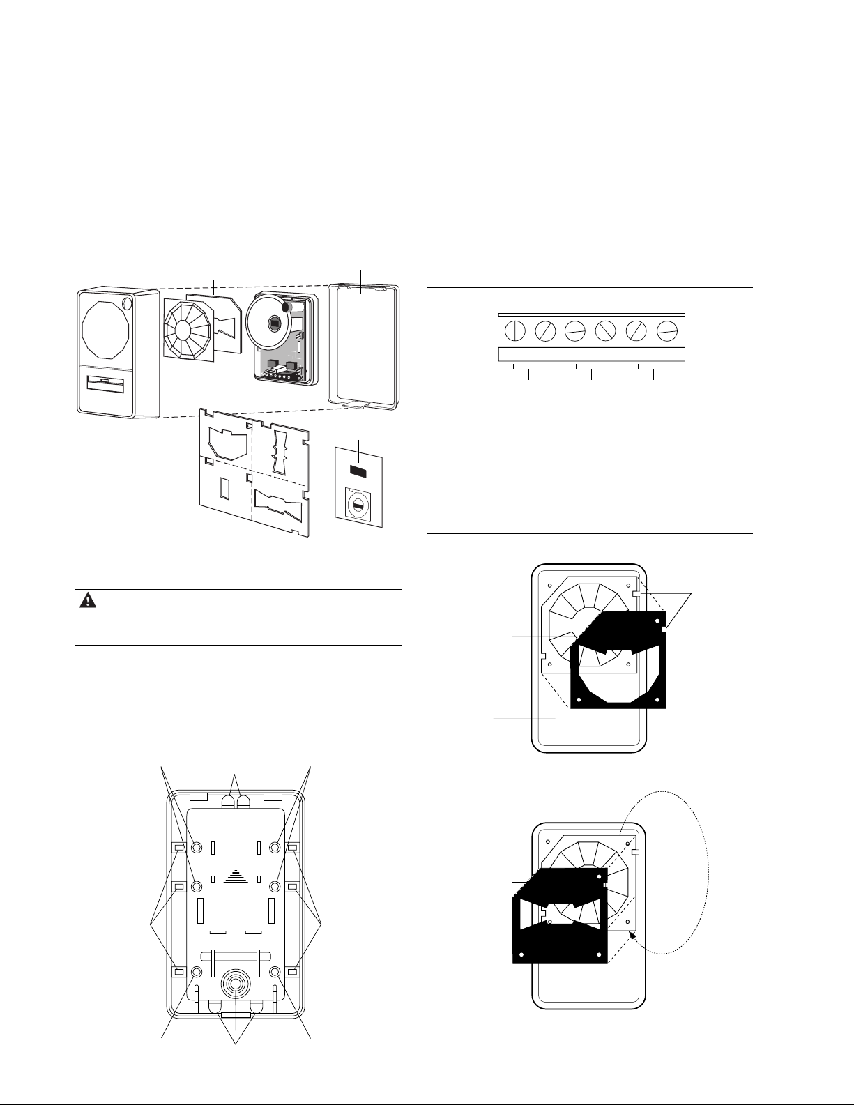
1. Remove the front cover (Figure 1) by gently prying the unit
apart at the bottom. The front cover hinges at the top.
Figure 1. Exploded view
Front cover Back coverMasking
2. Remove the circuit board assembly by holding the pyro shield
(Figure 1) and pulling it out of the back cover.
CAUTION You must be free of static electricity before
3. Mount the back cover to a ceiling, wall, or corner (see
Mounting). For wall mounting, make sure the UP arrow is
pointing up (Figure 2). Use the appropriate mounting and
wiring knockouts.
Figure 2. Back Cover
Lens Pyro shield
plate
PET
ALLEY
WIDE
ANGLE
Masking kit
SINGLE
SPOT
V
E
R
T
I
C
A
L
PET
ALLEY
B
A
R
R
I
E
R
handling sensor circuit boards. Touch a
grounded, bare metal surface before touching
circuit boards or wear a grounding strap.
Ceiling mount
mask sticker
6255/5885
Ceiling Mount Mask
Peel and stick to
groove side of lens.
Locate as shown.
4. Snap the circuit board assembly back onto the back cover by
aligning the lower edge of the board with the circuit board
guides and pressing it into place.
5. Strip back the outer jacket on the wiring cable to allow it to
flex in the case. Make sure the cable is slack in the ceiling or
wall to avoid stressing the wires at their connections. Connect
the wires as shown in Figure 3. The unit should be connected
to a UL listed power supply capable of providing 4 hours of
standby power.
Figure 3. Wiring
-+
T erminals for power
9-16 VDC
PIR
NC
Terminals for
PIR relay
PIR
COM
GBNCGB
COM
T erminals for
glassbreak relay
6. Choose a masking plate, if needed (see Zone patterns) and cut
to match the lens. Insert the masking plate behind the lens on
the front cover by pressing it over the three mounting pins
(Figure 4). To correctly mount the Pet Alley mask (Figure
5), the lens must be removed from the front cover, rotated
180 degrees, and cut to fit. Once the front cover is installed,
the masking plate will be held tight against the lens.
Figure 4. Inserting a masking plate
Align notch
with dimple
Cut to match lens
Inside of
front cover
Wall or ceiling
mount knockouts
Corner mount
knockouts
Wall or ceiling
mount knockouts
Wiring
knockouts
MADE IN U.S.A.
1-800-547-2556
UP
Wiring knockouts
Wall or ceiling
mount knockouts
Corner mount
knockouts
Wall or ceiling
mount knockouts
Figure 5. Using the pet alley masking plate
Rotate
Cut to match lens
PET
lens 180°
ALLEY
Inside of
front cover
ROTATE LENS
180
o
7. Replace the front cover and test the unit (see Testing the
sensor).
Page 2
ShatterPro Plus 5885
2
Installation Instructions
Mounting
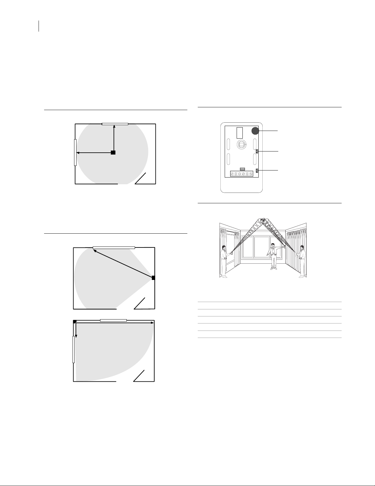
For ceiling mount (Figure 6):
1. Mount unit in direct line of sight of windows to be protected.
2 . Sensor can be mounted as close as 3.3 feet (1 m) from glass
and up to 12 feet (3.7 m) from glass.
Note When ceiling mounted, be sure to use the the ceiling
Figure 6. Ceiling mount
For wall or corner mount (Figure 7):
1 . Do not aim sensor directly at window - install so PIR is
covering the area of room you expect to have occupied.
2 . Sensor can be mounted as close as 3.3 feet (1 m) from glass
and up to 12 feet (3.7 m) from glass.
mount mask sticker to reduce potential for false alarms.
Glassbreak
coverage
12 feet
12 feet
PIR coverage
To test the glassbreak only: Place Jumper J2 (Figure 8) on two
pins so the motion sensing device is separated from glassbreak.
Place the 5709C tester next to the microphone and put the unit
into test mode by firing off the tester. The unit will be blinking red.
Position yourself next to the glass you want to detect, select the
appropriate glass type, and test the unit If drapes or blinds are
present, test behind them (Figure 9). The LED will go solid red for
4 seconds if glass is within detection range.
Figure 8. Jumper locations
Microphone
Jumper J1 for
LED latch
Jumper J2 for
separate glassbreack
and PIR
Figure 9. Testing positions
®
Figure 7. Wall and corner mount
Wall mount
Glassbreak coverage
PIR coverage
Corner mount
12 feet Glassbreak coverage
PIR coverage
12 feet
Sensor testing
Test the sensor to confirm that the field of view is set correctly
and that the glassbreak detector will detect at the desired mounting
location.
To test the field of view: Walk into the intended occupied area.
The green LED should blink at 1 Hz for 1 minute. This means that
the sensor has adjusted to a presence in the room and turned off the
glassbreak alarm relay for 1 minute. It will turn the glassbreak on
only after no movement has been detected for 1 minute. The LED
will remain solid green for 4 seconds, indiating motion detection by
the PIR.
T est and alarm LED indicators
Glassbreak alarm 4 seconds solid red
Glassbreak test 1 Hz blinking red for 1 minute
Glassbreak latched Solid red
Hand clap test 2 red blinks
PIR alarm 4 seconds solid green
PIR shunting glassbreak 1 Hz blinking green for 1 minute
Note: Each time the glassbreak sensor alarms, it also goes into
test mode for 1 minute.
Hand clap test
The ShatterPro Plus can be checked by the installer or end-user
while in normal mode by simply clapping hands loudly under the
sensor. The LED will blink twice, but the sensor will not trip. This
verifies visually that the microphone and circuit board are
functioning.
When the ShatterPro Plus trips to an actual alarm condition, it will
latch solid for 4 seconds, then start blinking for 1 minute. At the
end of 1 minute, the LED will extinguish unless set for “LATCH-
ING LED”.
Latching LED
To use the latching LED, remove Jumper J1 (Figure 8) to latch the
LED for glassbreak. When the unit alarms for glassbreak, the LED
will remain solid red after exiting test mode. Reset the unit by
removing power for at least 1 second.
Page 3
3
Application tips
The ShatterPro Plus provides two separate relays, one for the
glassbreak sensor and one for the PIR. This configuration allows
the ShatterPro Plus to be used in a variety of applications.
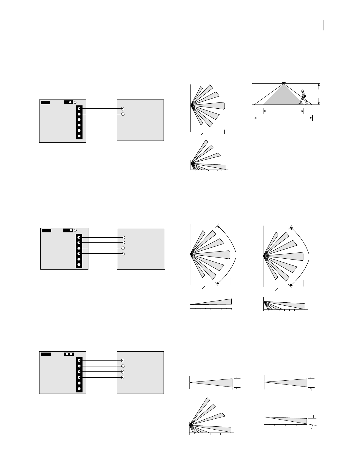
Application 1 - 24-hour glassbreak
Jumper 1
5885
circuit
board
In this application, the glassbreak relay is wired to a separate 24hour zone and Jumper 2 is placed across one pin. Any time a person
enters the PIR’s field of view, the glassbreak sensor will be disabled.
The glassbreak sensor will automatically turn back on one
minute after the PIR’s field of view is vacated. This applica-
tion is ideal for kitchens, garages, and other small, accousticallylive rooms that may incur loud occupant-generated sounds. It is
also good for 24-hour perimeter protection in commercial
installations that employ access control.
Application 2 - 24-hour glassbreak and interior backup
PIR
Jumper 1
Jumper 2
GB COM
GB NC
PIR COM
PIR NC
Jumper 2
24-Hour Zone
+
-
Control panel
Zone patterns
Wall mount no mask
Top V iew
0
9.1m
Side
View
7’
2.1m
0
Wall mount
with pet alley mask
Top V iew
30’
3.0m
38.4°
54°
20°
20°
38.4°
54°
40’
12.2m
10’
20’
30’
6.1m
9.1m
12.2m
360° ceiling mount
with ceiling mount mask
0°
15’ (4.8 m) x 20’ (6.2 m)
capture zone
25’ (7.2 m) diameter
coverage pattern
Note: Intruder must enter
coverage pattern 3-4 feet (1-
1.2 m) to cross one zone for
detection of alarm. False
alarm sources, such as
heaters, should be kept out of
40’
the coverage pattern.
Wall mount
with wide angle mask
Top V iew
5885
circuit
board
GB COM
GB NC
PIR COM
PIR NC
+
-
24-Hour Zone
Interior Zone
Control panel
In this application, the glassbreak relay is wired to a 24-hour zone,
the PIR relay is wired to a separate interior zone, and Jumper 2 is
placed across one pin. The PIR relay is wired to the control panel
to provide PIR backup for interior protection. Now when the
interior zone is armed, the PIR will also act as a motion detector
that will trigger an alarm if someone enters the room. This
application is an affordable way to get two sensors in one
installation.
Application 3 - Perimeter glassbreak and interior backup
PIR
Jumper 1
5885
circuit
board
Jumper 2
GB COM
GB NC
PIR COM
PIR NC
Non 24-Hour
Perimeter Zone
Interior Zone
+
-
Control panel
In this application, the glassbreak relay is wired to a separate
perimeter (non 24-hour) zone, the PIR relay is wired to a separate
interior zone, and Jumper 2 is placed across two pins. This
configuration is a very affordable way to get two sensors in one, a
glassbreak and a PIR. It’s perfect for installations that don’t require
24-hour operation, but are armed at night, during unoccupied hours,
or during quiet occupied hours.
0
30’
Side
View
0,9m
9.1m
3’
10’
3.0m
20’
6.1m
0
30’
9.1m
12.2m
12.2m
Wall mount with
vertical barrier mask
To p View
0
Side View
7’
2.1m
10’
20’
6.1m
30’
9.1m
12.2m
0
3.0m
40’
40’
40’
12.2m
40’
10°
90°
Side
View
7’
2.1m
0
30’
9.1m
10’
0
3.0m
Wall mount
with single spot mask
Top View
0
Side View
7’
2.1m
10’
0
3.0m
20’
6.1m
20’
6.1m
30’
9.1m
30’
9.1m
40’
12.2m
40’
12.2m
12.2m
40’
12.2m
90°
10°
40’
7°
Page 4
ShatterPro Plus 5885
4
Installation Instructions
Specifications
Electrical
Operational voltage 9 to 16 VDC
Current draw 15mA typical, 30 mA max.
Alarm outputs Normally closed, open 4 seconds on
alarm
On resistance 5 to 15 Ohms
Off resistance >1 MOhms
Maximum loop rating 16 VDC, 50 mA (relay or tamper loop)
Fails safe and opens on power loss
Wire gauge 14 - 22 AWG
Environmental
Lightning suppression 400 watts for 1 msec pulse
Operating temperature 0 to 120°F (-18 to 50°C)
RFI immunity 20 V/meter from 1 to 1000MHz
Humidity 10% to 90% noncondensing
PIR Features
Pulse count Bi-directional, 1 zone (2 pulses) with
motion verification
Range
1. Wide Angle (90°) 30 ft. x 30 ft. (9.1 m x 9.1 m),
7 ft. (2.1 m) mounting height
2. 360° Ceiling 15 ft. x 20 ft. (4.6 m x 6.1 m) at 8 ft.
(2.4 m) height, 16 ft. x 30 ft. (4.9 m x
9.1 m) at 12 ft. (3.7 m) height, ceiling
mounting height up to 12 ft. (3.7 m)
3. Single Spot 40 ft. (12.2 m) range, 7 ft. (2.1 m)
mounting height
4.Vertical Barrier 40 ft. (12.2 m) range, 7 ft. (2.1 m)
mounting height
5. Pet Alley (90°) 30 ft. (9.1 m) range, 3 ft. (0.9 m)
mounting height
Acoustic Glassbreak Features
Microphone Omni directional 360° electret
Sensitivity setting Factory set
Range 12 ft. (3.7 m) from ceiling to window
wall, 12 ft. (3.7 m) to side wall
Glass types detected:
Plate glass 1/8 in. (3.2 mm) to 1/4 in. (6.4 mm)
Tempered glass 1/8 in. (3.2 mm) to 1/4 in. (6.4 mm)
Wired glass 1/4 in. (6.4 mm)
Laminated glass 1/4 in. (6.4 mm)
Mounting location Ceiling or any wall except opposite
wall
Min. distance from glass 3.3 ft. (1 m)
Min. glass size 1 ft. (0.3 m) x 2 ft. (0.6 m)
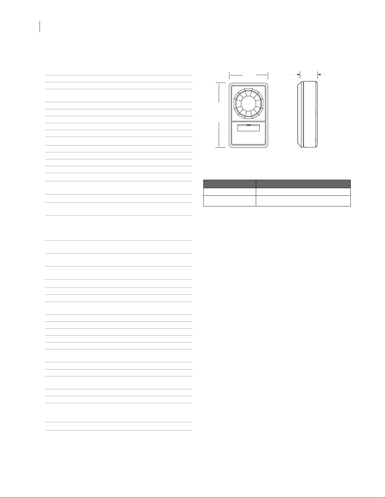
Dimensions 3.7 in. (9.4 cm) H x 2.2 in. (5.6 cm) W x
1.2 in. (3.1 cm) D
Housing material Flame retrardant ABS plastic
Color White/white
Shunting feature Glassbreak automatically turns back on
1 minute after vacating PIR’s field of
view
Listings UL639
Dimensions
2.2”
➝
(5.6 cm)
➝
➝
3.7”
(9.4 cm)
➝
Ordering information
Model number Description
5885-W ShatterPro
5709C Hand held tester
Plus
1.2”
(3.1 cm)
12345 SW Leveton Drive
GE Security
Tualatin, OR 97062
503-692-4052
USA & Canada: 800-547-2556
Tech Support: 800-648-7424
www.ge-security.com
12287G / September 2004
 Loading...