

Page 1

GE Healthcare
3900/3900P Pulse Oximeter
TruTrak®+
User’s Manual
♥
Page 2

Page 3
GE Healthcare
3900/3900P Pulse Oximeter
TruTrak®+
User’s Manual
♥
6050-0006-406
March 2005
Page 4

Important
Rx Only (USA)
Attention! Consult the accompanying instructions before using this
device.
The safety, reliability, and performance of this device can be assured only under
the following conditions:
• If it is used according to the accompanying operating instructions.
• If fittings, extensions, readjustments, changes, or repairs are carried out by
agents authorized by Datex-Ohmeda.
• If it is used in buildings having ground equalization wiring that complies with
relevant local standards and regulations.
This device must be cleaned and checked periodically. Do not use a defective
device. Parts that are broken, missing, plainly worn, distorted, or contaminated
should be replaced immediately. If repair or replacement becomes necessary,
request service advice from Datex-Ohmeda. Do not repair this device or any of its
parts other than in accordance with written instructions provided by DatexOhmeda.
The user of this device shall have the sole responsibility for any malfunction that
results from improper use, faulty maintenance, improper repair, unauthorized
service, damage, or alteration by anyone other than Datex-Ohmeda.
Trademarks
Datex®, Ohmeda®, OxyTip®, PerfTrak®, TeleOximetry®, TruTrak®, and PIr® are
the property of GE Healthcare Finland Oy. All other product and company names
are the property of their respective owners.
0537
GE Healthcare Finland Oy
Helsinki, Finland
+358 10 394 11
www.gehealthcare.com
© 2005 General Electric Company. All rights reserved.
Page 5

Table of Contents
1/Overview
Product description.....................................................................................................................................1-1
Intended use........................................................................................................................................1-1
TruTrak+ technology.......................................................................................................................1-1
PIr pulsatile value............................................................................................................................1-2
Other features.....................................................................................................................................1-2
Functional components................................................................................................................1-3
Principles of operation..................................................................................................................1-4
Calibration..............................................................................................................................1-5
Front panel.......................................................................................................................................................1-6
Alarm silence button......................................................................................................................1-7
Alarm silence ........................................................................................................................1-7
All mute....................................................................................................................................1-7
Numeric display...............................................................................................................................1-7
Graphic display .................................................................................................................................1-8
SpO2 alarm limits, high and low............................................................................................1-9
Pulse rate alarm limits, high and low ..................................................................................1-9
Display contrast adjuster..............................................................................................................1-9
Power/Standby button/AC power light ..............................................................................1-9
Battery operation.................................................................................................................1-9
Carrying handle ............................................................................................................................. 1-10
Sensor connector...........................................................................................................................1-10
Screen option buttons................................................................................................................. 1-10
Pulse beep volume button....................................................................................................... 1-11
Alarm volume button..................................................................................................................1-11
Printer..................................................................................................................................................1-11
Rear panel......................................................................................................................................................1-12
Power entry module .................................................................................................................... 1-12
Equipotential ground connector........................................................................................... 1-12
Product information label ........................................................................................................ 1-12
Mode Switch .................................................................................................................................... 1-12
RS-232 serial/analog connector.............................................................................................1-12
Precautions....................................................................................................................................................1-13
Warnings............................................................................................................................................1-13
Failure of operation........................................................................................................1-13
Data validity........................................................................................................................1-13
Explosion hazard..............................................................................................................1-13
Electrical shock hazard ................................................................................................ 1-13
Electrical shock and flammability hazard ........................................................ 1-14
Patient safety.......................................................................................................................1-14
Patient safety (sensors)..................................................................................................1-14
Patient safety (modem).................................................................................................1-14
RS-232 system interconnection................................................................................1-15
Cautions..............................................................................................................................................1-15
Handle the monitor with care.................................................................................. 1-15
Cleaning................................................................................................................................1-15
Sensors...................................................................................................................................1-15
Battery.....................................................................................................................................1-15
Printer.....................................................................................................................................1-15
Disposal.................................................................................................................................. 1-15
i
Page 6

Table of Contents
2/Setup and Operations
Powering the oximeter...............................................................................................................................2-1
Setup....................................................................................................................................................................2-2
Factory settings..................................................................................................................................2-2
Mode switch settings......................................................................................................................2-3
Checkout procedure...................................................................................................................................2-5
Signal and data validity............................................................................................................................2-8
Plethysmographic waveform.....................................................................................................2-8
Numeric display............................................................................................................................2-10
Waveform screen button.......................................................................................................................2-11
Menu button.................................................................................................................................................2-11
Main menu function key buttons.........................................................................................2-11
LABELS............................................................................................................................................................2-12
Locking label lines........................................................................................................................ 2-14
SETTINGS.....................................................................................................................................................2-15
Date and time...............................................................................................................................................2-17
Trend options...............................................................................................................................................2-18
Trend function keys.....................................................................................................................2-19
Trend data ......................................................................................................................................... 2-20
Patient function key lockout...............................................................................................................2-22
Before powering on the oximeter ..............................................................................2-2
After powering on the oximeter .................................................................................2-2
Language selection.............................................................................................................2-3
Averaging mode...................................................................................................................2-4
PIr pulsatile value display.............................................................................................2-4
EMI line frequency ............................................................................................................2-4
Low perfusion.......................................................................................................................2-8
Signal noise............................................................................................................................2-9
SpO2........................................................................................................................................2-10
Pulse rate .............................................................................................................................. 2-10
PIr pulsatile value............................................................................................................2-10
Summary: custom patient labels...........................................................................2-12
Select field function keys................................................................................2-13
– / + Select character function keys....................................................................2-13
Function key...........................................................................................................2-13
CLEAR....................................................................................................................................2-14
SAVE LIMITS.....................................................................................................................2-15
ALL MUTE...........................................................................................................................2-16
BAUD RATE........................................................................................................................2-16
ANALOG...............................................................................................................................2-16
MODE.....................................................................................................................................2-16
OUTPUT...............................................................................................................................2-16
CONTRAST (3900P printer only)...........................................................................2-16
Date..........................................................................................................................................2-17
Time.........................................................................................................................................2-17
Scroll buttons.........................................................................................................2-19
Shift buttons...................................................................................................2-19
CLEAR....................................................................................................................................2-19
Viewing time scale for display................................................................................. 2-20
ii
Page 7

Table of Contents
3/Messages and Troubleshooting
Messages.............................................................................................................................................................3-1
Alarm categories............................................................................................................................................3-5
High priority........................................................................................................................................3-5
Medium priority................................................................................................................................3-5
Low priority.........................................................................................................................................3-6
System failure.....................................................................................................................................3-6
Troubleshooting.............................................................................................................................................3-7
4/Printer
Printer buttons................................................................................................................................................4-2
Print real-time data..........................................................................................................................4-2
Summary statistics only................................................................................................................4-2
Trend print...........................................................................................................................................4-2
Stop print/advance paper ...........................................................................................................4-3
Printed data samples..................................................................................................................................4-3
Printer maintenance...................................................................................................................................4-5
Replacing the paper roll..............................................................................................................4-5
Removing a paper jam..................................................................................................................4-6
5/TeleOximetry
Using a modem: summary.....................................................................................................................5-1
Modem connection......................................................................................................................................5-2
Modem status..................................................................................................................................................5-3
Select data.........................................................................................................................................................5-4
Send......................................................................................................................................................................5-5
FAX .......................................................................................................................................................................5-6
Fax transmission messages.........................................................................................................5-7
Canceling a transmission (FAX CANCELED)..................................................................5-7
Sending data to a remote computer..................................................................................................5-8
Remote computer requirements................................................................................5-8
Preparing for transmission............................................................................................5-8
Dialing and answering calls at the remote computer...................................5-8
Receiving the data file at the remote computer...............................................5-8
Remote computer.............................................................................................................................5-9
Wait for call .........................................................................................................................................5-9
Canceling a transmission (TRANSMISSION CANCELED)..................................5-10
Transmission failure messages..........................................................................................................5-10
Modem setup................................................................................................................................................5-11
Guard tone.........................................................................................................................................5-11
Custom initialization string ..................................................................................................... 5-11
Default initialization string.........................................................................................5-12
Sample reports............................................................................................................................................5-13
Remote computer report format...........................................................................................5-13
InstaReport fax—SpO2 mode...................................................................................................5-14
InstaReport fax—PIr mode ........................................................................................................ 5-16
iii
Page 8

Table of Contents
6/Maintenance and Service
Cleaning.............................................................................................................................................................6-1
Oximeter (with or without the printer) ...............................................................................6-1
Recharging the battery..............................................................................................................................6-2
Replacing the battery.................................................................................................................................6-2
Replacing the fuses.....................................................................................................................................6-3
Repair policy and procedure.................................................................................................................6-4
Packaging and return procedure ............................................................................................6-4
Parts list ..............................................................................................................................................................6-5
7/Compliance and Specifications
Compliance with standards....................................................................................................................7-1
General safety requirements......................................................................................................7-1
Electromagnetic compatibility (EMC) ..................................................................................7-2
Safety checks for software...........................................................................................................7-2
Specifications..................................................................................................................................................7-3
Circuitry.................................................................................................................................................7-3
Audio indicators................................................................................................................................7-3
Audible alarms..................................................................................................................................7-3
Displays..................................................................................................................................................7-4
Mode switch........................................................................................................................................7-4
SpO2.........................................................................................................................................................7-4
Pulse rate...............................................................................................................................................7-5
PIr pulsatile value............................................................................................................................7-5
Sensor emitter wavelength ranges.........................................................................................7-5
Environmental....................................................................................................................................7-5
Electrical................................................................................................................................................7-5
RS-232 serial/analog connector................................................................................................7-6
Dimensions and weight ................................................................................................................7-6
Electromagnetic effects....................................................................................................7-2
Alarm limits ...........................................................................................................................7-3
Interfering substances......................................................................................................7-4
Battery........................................................................................................................................7-5
Power.........................................................................................................................................7-6
Current leakage....................................................................................................................7-6
Fuses...........................................................................................................................................7-6
Serial output ..........................................................................................................................7-6
Analog output........................................................................................................................7-6
iv
Page 9

Table of Contents
A/Screen Maps
Screen maps...................................................................................................................................................A-1
B/Communications
Serial device communications..............................................................................................................B-1
Requirements....................................................................................................................................B-1
RS-232 interface cable—serial pinout.....................................................................B-2
Connection..........................................................................................................................................B-2
Serial communication output..................................................................................................B-3
Auto-output mode..............................................................................................................B-4
Trend-output mode ........................................................................................................... B-4
Analog device communications...........................................................................................................B-4
RS-232 serial/analog interface cable—analog pinout..................................................B-5
Index
Warranty
v
Page 10

List of Figures
Name Page
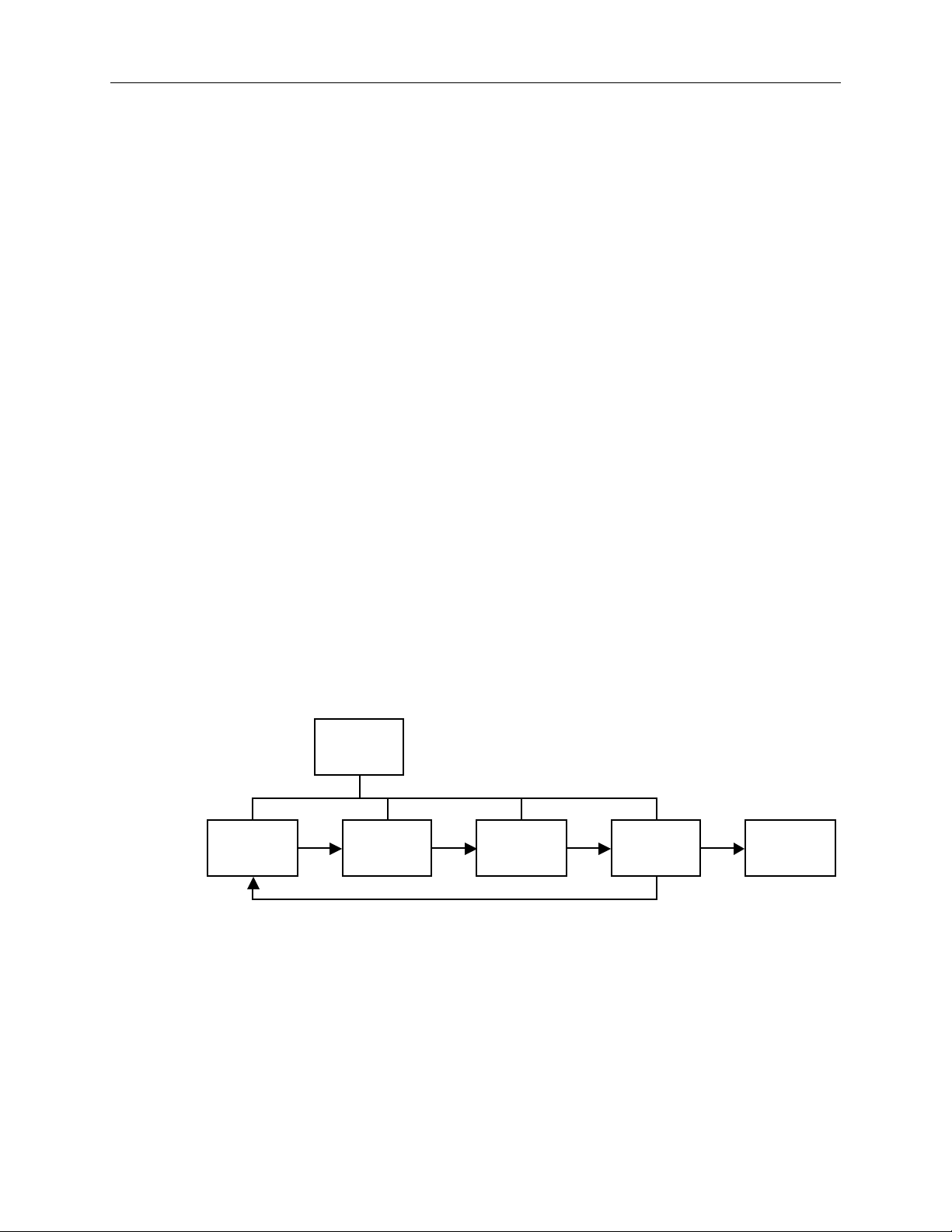
Figure 1-1. Signal processing block diagram...........................................................................1-3
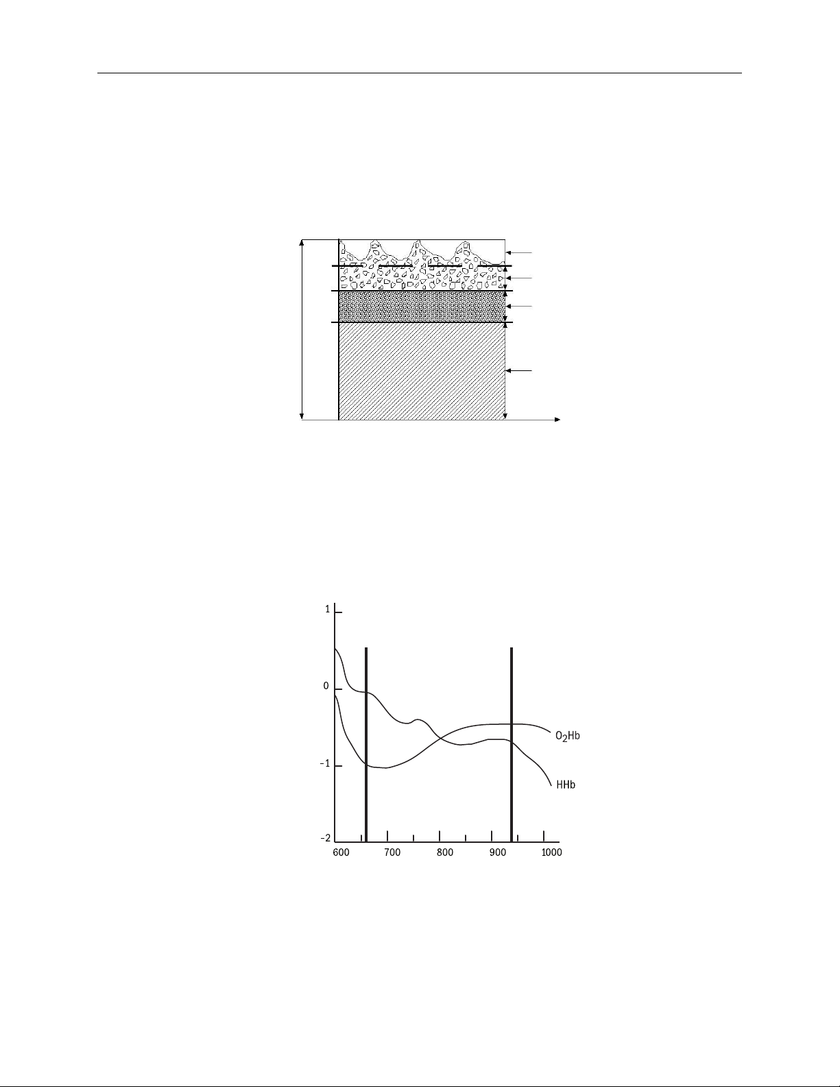
Figure 1-2. Comparative light absorption...................................................................................1-4
Figure 1-3. Extinction versus wavelength graph....................................................................1-4
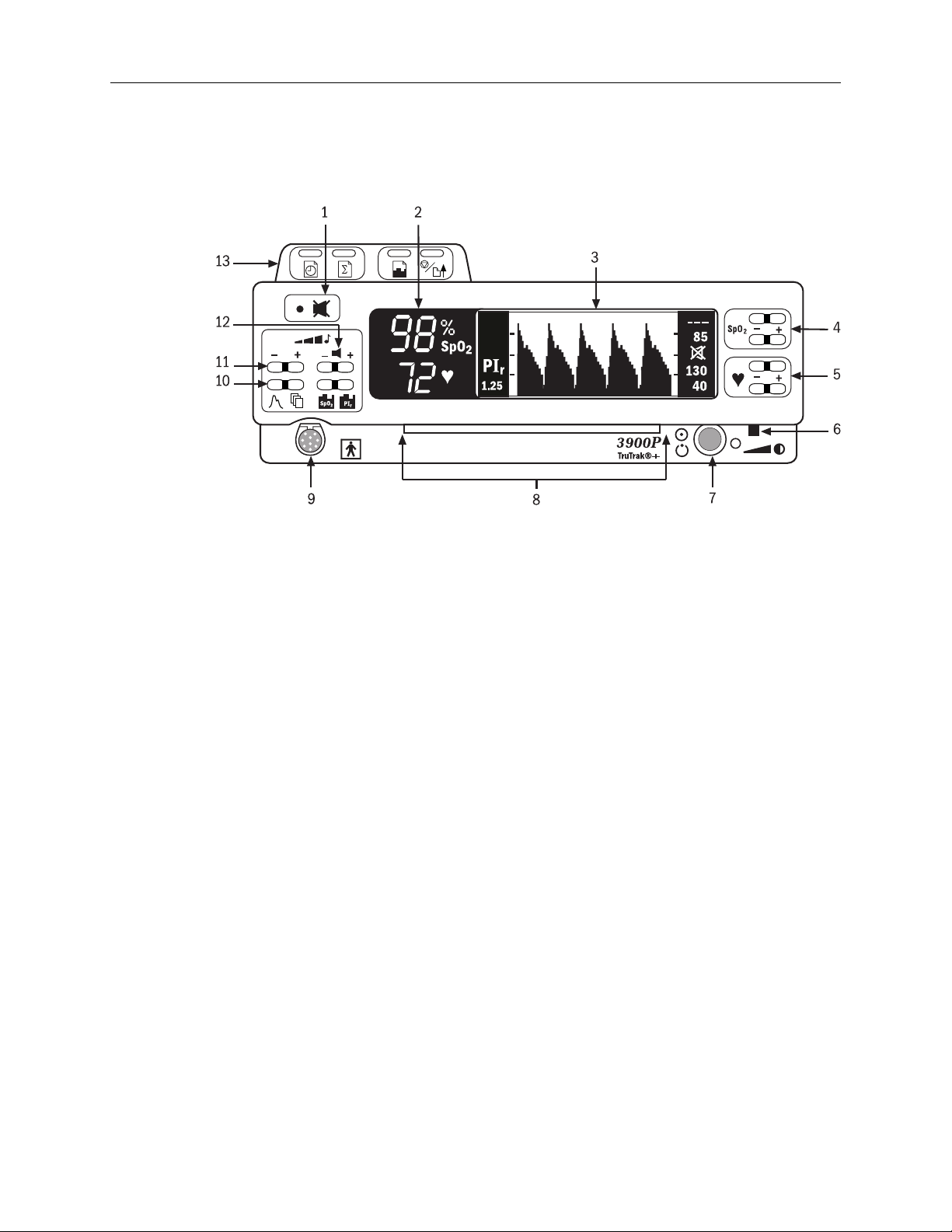
Figure 1-4. 3900P Pulse Oximeter front panel.........................................................................1-6
Figure 1-5. 3900/3900P Pulse Oximeter rear panel ........................................................... 1-12
Figure 2-1. Typical adult plethysmographic waveform .....................................................2-8
Figure 2-2. Typical neonate plethysmographic waveform...............................................2-8
Figure 2-3. Low perfusion waveform............................................................................................2-9
Figure 2-4. Noisy plethysmographic waveform ......................................................................2-9
Figure 2-5. Main menu.......................................................................................................................2-11
Figure 2-6. LABELS screen .............................................................................................................. 2-13
Figure 2-7. Settings screen options.............................................................................................. 2-15
Figure 2-8. DATE/TIME screen......................................................................................................2-17
Figure 2-9. Trend screens.................................................................................................................2-18
Figure 4-1. 3900P printer......................................................................................................................4-2
Figure 4-2. SELECT HOURS screen .............................................................................................4-2
Figure 4-3. Printed data samples.....................................................................................................4-4
Figure 4-4. Replacing the paper roll .............................................................................................4-5
Figure 4-5. Removing the paper-feed cover ..............................................................................4-6
Figure 5-1. MODEM STATUS screen ...........................................................................................5-3
Figure 5-2. SELECT HOURS screen .............................................................................................5-4
Figure 5-3. SEND screen......................................................................................................................5-5
Figure 5-4. PHONE NUMBER screen ..........................................................................................5-6
Figure 5-5. SENDING FAX screen..................................................................................................5-7
Figure 5-6. SENDING DATA screen..............................................................................................5-9
Figure 5-7. MODEM SETUP screen............................................................................................ 5-11
Figure 5-8. INITIALIZATION STRING screen......................................................................5-12
vi
Page 11

1/Overview
This chapter
• Introduces the product, including the principles of its operation.
• Describes the oximeter’s controls and features.
• Lists the precautions you must take when using the oximeter.
Product description
The Datex-Ohmeda Model 3900 and Model 3900P pulse oximeters with TruTrak
technology feature two easy-to-read displays that present patient data and status
information.
• The numeric display shows the SpO2 and pulse rate values.
• The graphic display shows the plethysmographic waveform (or trend data),
You can send current or trend data (SpO2 or PIr pulsatile value) to the built-in
printer (3900P only) and to a computer. You can connect a modem to the monitor
and use the TeleOximetry® feature to transmit data to a fax machine or computer.
You can also set the date and time and create labels for individual data records.
Intended use
The 3900/3900P pulse oximeter with TruTrak+ technology is indicated for spotchecking and continuous monitoring of functional oxygen saturation and pulse
rate, including monitoring during conditions of clinical patient motion.1 This
device is intended for use with adult, pediatric, and neonatal patients in both
hospital and non-hospital environments.
messages, the Relative Perfusion Index (PI
and low alarm limit settings for SpO2 and pulse rate.
Important: Only OxyTip
®
+ sensors can be used with this monitor.
®
) pulsatile value, and the high
r
®
+
TruTrak+ technology
TruTrak+ technology improves pulse oximetry performance during conditions of
clinical patient motion. In the clinical environment, oximetry readings are affected
by several types of patient motion. The types of motion include clenching,
pressing, and rubbing as well as extending, flexing, and kicking. Unlike motion
technologies that use only a single method to correct for motion, TruTrak+ selects
1
Anesthesia & Analgesia. 2002;94,1S, S54-S60
1-1
Page 12

3900/3900P User’s Manual
one of many proprietary motion-correction algorithms, depending on the type and
intensity of the motion.
TruTrak+ technology employs a patented five-step process that consists of
1) high-speed data sampling; 2) motion identification, quantification, and
correction; 3) calculation of the SpO2 value; 4) weighting and averaging of the
SpO2 value; and 5) the display of an improved SpO2 value. The result of this
process is a more accurate and stable displayed SpO2 value, with fewer false
alarms or dashed displays.
Important: For TruTrak+ performance, the averaging mode must be set to Long.
See Setup in chapter 2.
PIr pulsatile value
The PIr pulsatile value indicates the strength of the pulse signal at the sensor site:
the higher the PIr value, the stronger the pulse signal. A strong pulse signal
increases the validity of SpO2 and pulse rate data.
PIr is a relative value that varies from patient to patient. Clinicians can use the PI
value to compare the strength of the pulse signal at different sites on a patient in
order to locate the best site for the sensor (the site with the strongest pulse signal).
You can choose to display or not display the PIr value (see Setup in chapter 2).
Other features
• PerfTrak® waveform display, an automatic scale of the plethysmographic
• Large SpO2 digital display for clear differentiation from the pulse rate value.
• Backlit display and contrast control for excellent visibility in subdued lighting
• Direct access to user-selectable high and low alarm limits for SpO2 and pulse
• An audible pulse indicator with an adjustable volume; the automatic pitch
• Visual and audible (adjustable volume) alarms.
• Ability to save volume and alarm limit settings.
• An alarm-silence feature that silences audible alarms for 120 seconds.
• An all-mute feature that silences audible alarms until deactivated. This ability
• Automatic tiered alarm messages.
• Language options that display the monitor’s screen text and, in most cases,
• Short, medium, or long SpO2 response averaging modes.
• Automatic storage of alarm conditions and up to 24 hours of SpO2, pulse rate,
r
waveform to provide a relative indication of the sensor site perfusion level.
conditions; adjustable viewing angle, using the pull-down feet under the
monitor.
rate.
modulation reflects changing SpO2 level.
to mute all alarms can be disabled.
printed or transmitted data in the selected language.
and PIr pulsatile value data.
1-2
Page 13
• Ability to print or transmit the data in trend memory, along with custom
patient labels, alarm limit violations, and time stamps.
• Viewable SpO2 or PIr pulsatile value trend data.
• Custom patient labels that appear on printer, fax, modem, and serial
communication output.
• Two analog output channels, SpO2 and pulse rate, for connecting a chart
recorder or polysomnography machine.
• An automatic self-test and calibration check at start-up. After start up, the
oximeter continuously performs background self-tests.
• Rechargeable, sealed, lead-acid battery operation, including battery status
reporting.
• A lock button function that prevents unintended changes to settings while
monitoring a patient.
Functional components
The 3900/3900P oximeter uses the following key electrical component elements to
determine SpO2, pulse rate, and PIr pulsatile values:
• The sensor
• Sensor-signal processing
• Microprocessor calculations
1/Overview
The sensor consists of
• The light source—red and infrared light-emitting diodes (LEDs)
• The photodetector—an electronic device that produces an electrical current
proportional to incident light intensity
Timing
Control
Sensor
Figure 1-1. Signal processing block diagram
The two light wavelengths generated by the LEDs pass through the tissue at the
sensor site. The photodetector collects this light (partially absorbed and modulated) and converts it into an electronic signal that is sent to the oximeter for
further processing.
The electronic circuitry receives the photodetector’s electronic signal, processes it,
and passes it on to the microprocessor for calculation of the SpO2, pulse rate, and
the PIr pulsatile value.
Analog
Processing
A/D
Converter
Digital
Processing
Input/
Output
1-3
Page 14
3900/3900P User’s Manual
Principles of operation
The 3900/3900P pulse oximeter uses a two-wavelength pulsatile system—red and
infrared light—to distinguish between oxygenated (O2Hb) and reduced (HHb)
hemoglobin, each of which absorbs different amounts of light emitted from the
oximeter sensor. The system then calculates the relative percentage of these two
constituents and displays SpO
Absorption
.
2
Variable absorption
(due to arterial pulse)
Arterial blood absorption
Venous blood absorption
Other tissue absorption
Time
Figure 1-2. Comparative light absorption
Arterial blood pulsation at the test site modulates transmission of the oximeter
sensor’s light. Since other fluids and tissues present generally don’t pulsate, they
don’t modulate the light passing through that location. The attenuation of light
energy due to arterial blood flow is detected and isolated by using the pulsatile
portion of the incoming signal. PIr pulsatile value is a measure of the relative size
of this portion of the signal.
(Red)
660 nm
Extinction (10x)
(Infrared)
940 nm
1-4
Wavelength (nm)
Figure 1-3. Extinction versus wavelength graph
The sensor’s photodetector converts the light, which is partially absorbed and
modulated as it passes through the tissue sample, into an electronic signal. Since
O2Hb and HHb allow different amounts of light to reach the photodetector at the
selected wavelengths, the electronic signal varies according to the light source that
Page 15

1/Overview
is “on” and the oxygenation of the arterial hemoglobin. Analog and digital signal
processing then converts the light-intensity information into SpO2, pulse rate, and
PIr pulsatile values for display on the monitor.
Calibration
A CO-oximeter typically uses four or more wavelengths of light and calculates
reduced hemoglobin (HHb), oxyhemoglobin (O2Hb), carboxyhemoglobin (COHb),
and methemoglobin (MetHb). Datex-Ohmeda pulse oximeters use two
wavelengths ranges, 650 nm - 670 nm and 930 nm - 950 nm, both with an average
power of less than 1 mW. These wavelengths are used to calculate the presence of
O2Hb and reduced HHb. Because of this, pulse oximetry readings will be
different than CO-oximetry readings in situations where a patient’s COHb or
MetHb are increased.
Two different methods of calibration are currently used by manufacturers of pulse
oximeters: fractional and functional.
Important: This pulse oximeter uses the functional calibration method. The user
cannot change the calibration method to fractional.
• Fractional saturation is represented mathematically as the percentage of the
total amount of hemoglobin carrying oxygen. It is determined by dividing the
oxyhemoglobin by the total hemoglobin.
O2Hb
Fractional SpO2 =
• Functional saturation is represented mathematically as the percentage of
hemoglobin capable of carrying oxygen that is carrying oxygen.
Functional SpO2 =
The calculation of SpO
methemoglobin (MetHb), and no other pigments. Appreciable variation from these
values will influence SpO2 accuracy. These values are based on the Ohmeda
Pulse Oximeter Empirical Calibration Study.
( )
Hb
TOTAL
( )
Hb
TOTAL
assumes 1.6% carboxyhemoglobin (COHb), 0.4%
2
x 100 =
O2Hb
– COHb – MetHb
( )
O2Hb + HHb + COHb + MetHb
O2Hb
x 100 =
x 100
O2Hb
( )
O2Hb + HHb
x 100
1-5
Page 16
3900/3900P User’s Manual
Front panel
NOTE: The 3900 model does not have the built-in printer (item 13).
♥
Figure 1-4. 3900P Pulse Oximeter front panel
1 Alarm silence button
2 Numeric display (LED)
3 Graphic display (LCD)
4 SpO2 alarm limits, high/low setting buttons
5 Pulse rate alarm limits, high/low setting buttons
6 Display contrast adjust slide
7 Power/Standby button
8 Carrying handle
9 Sensor connector
10 Screen display option buttons
11 Pulse beep volume button
12 Alarm volume button
13 Built-in printer (3900P)
1-6
Page 17
1/Overview
1 Alarm silence button
This button has two functions:
• 120-second alarm silence—activated by a single press.
• Continuous all mute—activated by three quick presses (if the all-mute
feature is enabled). Press once to deactivate.
Alarm silence
When an active alarm condition exists, press this button to silence the audible
portion of the alarm for 120 seconds. The flashing red or yellow alarm light
becomes a steady light. If an alarm condition still exists after 120 seconds, the
audible tone and flashing light resume.
Exceptions: Both NO SENSOR and SENSOR OFF audible alarms will not be
activated until after the unit obtains a valid signal. The same conditions apply
to an active audible alarm for NO SENSOR, SENSOR OFF, or SENSOR
FAILURE that has been silenced; i.e., once the sensor alarm condition is
acknowledged by silencing the audible alarm, a new audible alarm will not
sound until the condition has been cleared and the unit obtains a valid signal.
NOTE: Pressing the alarm silence button produces 120 seconds of silence,
regardless of other alarm conditions that may occur during this 120-second
interval, except for the SYSTEM FAILURE, CONNECT UNIT TO LINE
POWER, and BUTTON STUCK alarms.
All mute
To continuously silence any alarm that can be silenced, press the alarm
silence button three times within three seconds. After you have activated all
mute, the all mute icon flashes between the SpO2 and pulse rate alarm limit
settings on the right side of the screen display. (On Japanese menu screens,
the icon flashes at the upper right beside the first menu option.) When an
alarm condition occurs, the alarm button light flashes and the alarm message
appears on the waveform display but no audible alarm sounds.
When all mute is active, press the alarm silence button once to deactivate this
feature and enable all audible alarms.
The ability to mute all alarms continuously can be disabled; see SETTINGS,
ALL MUTE in chapter 2.
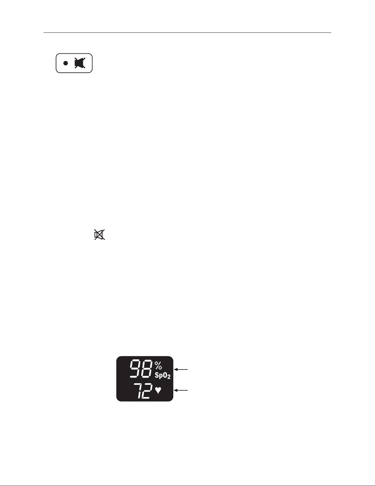
2 Numeric display
SpO2 numeric area—calculated SpO
Pulse rate numeric area—calculated pulse rate
2
1-7
Page 18
3900/3900P User’s Manual
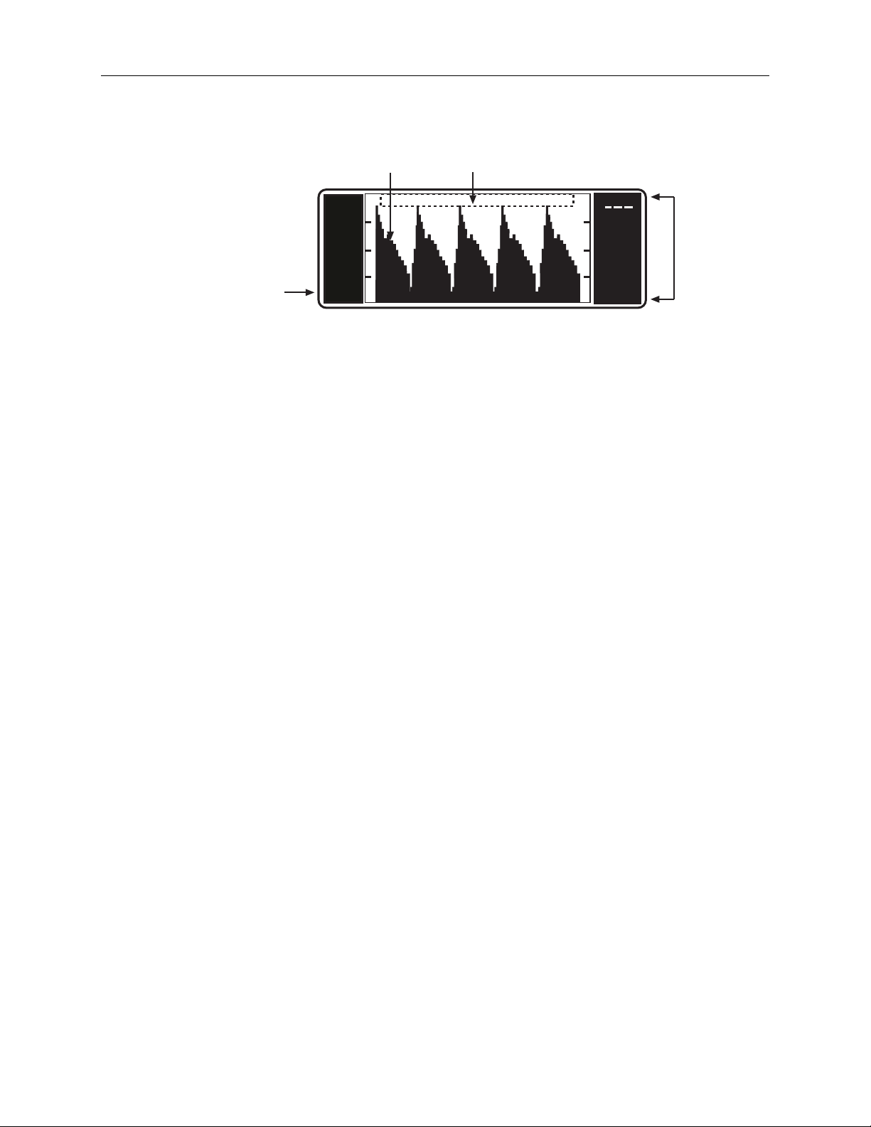
3 Graphic display
21
85
3
PI
r
4
1 Plethysmographic waveform (also the display area for trend data, screen
2 Message area.
3 SpO2 and pulse rate alarm limits
1.25
menus, and options)
The PerfTrak waveform display appears after the monitor has detected
data from the sensor. It represents the blood volume change of the
hemodynamic system, assuming no other factors (e.g., motion artifact) are
present. This waveform scales automatically to the perfusion level or
strength of the signal being received at the patient monitoring site.
See Trend options in chapter 2 for detailed descriptions of the SpO2 and
PIr pulsatile value trend screens.
Status and alarm messages appear above the waveform area on the
waveform display (the height of the waveform is reduced while messages
are displayed). Status messages give you information about the oximeter's
operating condition. Alarm messages alert you to conditions that need
your attention. See chapter 3 for complete alarm and status message
information.
The high and low alarm limit settings appear here. If a limit is set to OFF,
three dashes appear in the location for that limit.
130
40
1-8
When an SpO2 or pulse rate limit is violated, the LED on the numeric
display and the LCD’s limit value flashes for that alarm.
4 PIr pulsatile value
Dashes (- - -) appear if the following conditions exist: no sensor is
connected to the unit, the sensor is not attached to the patient, the sensor
has failed, there is insufficient light penetrating the tissue site, or there is
too much ambient light.
Page 19
SpO
♥
1/Overview
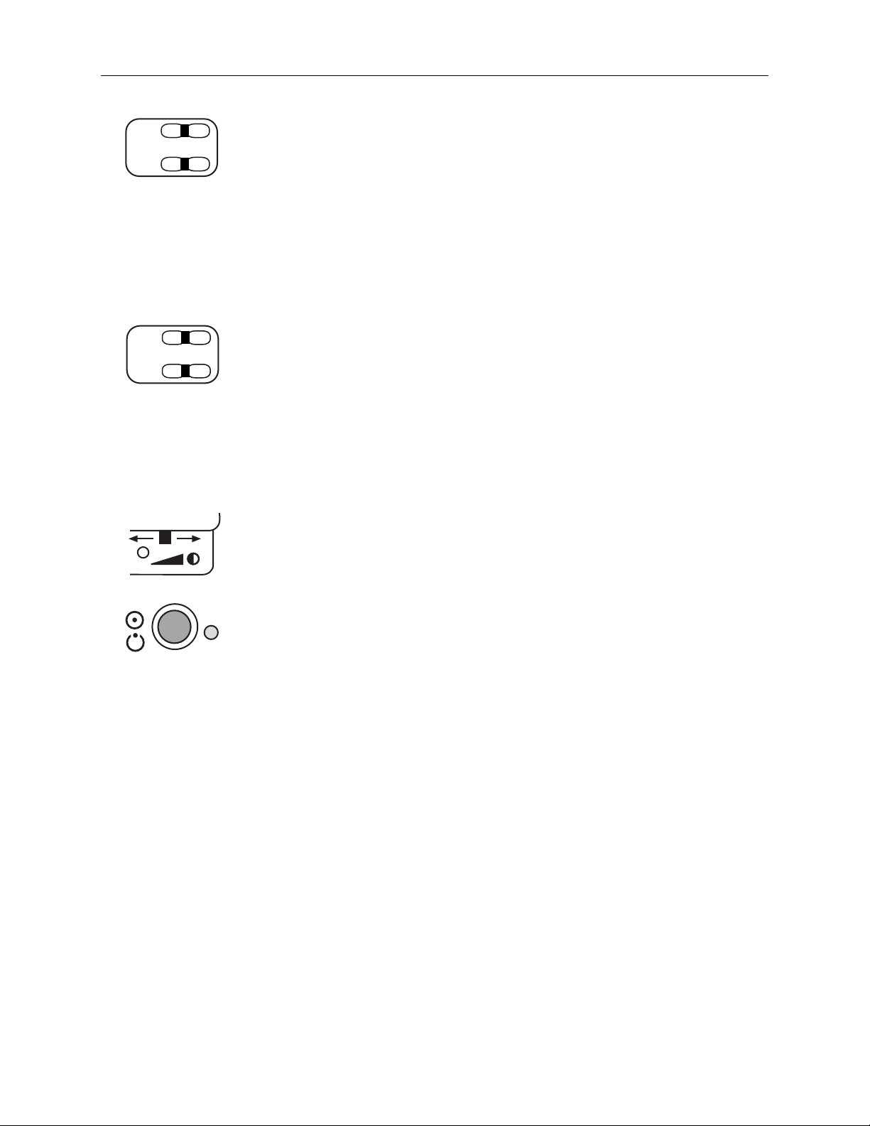
4 SpO2 alarm limits, high and low
2
+
–
While viewing the waveform screen, the top button sets the high alarm limit
and the bottom button sets the low alarm limit. For either limit, press the +
side of the button to raise the value or the – side to lower it. As you press one
of these buttons, the values do not cycle through the available settings; e.g.,
when you reach 100, the value does not cycle (or wrap) to 50 or OFF and vice
versa.
When you are using menu options, these two buttons become function
keys—the function each performs depends on the options available in the
menu on the screen; see Menu button in chapter 2.
5 Pulse rate alarm limits, high and low
+
–
While viewing the waveform screen, the top button sets the high alarm limit,
the bottom button sets the low alarm limit. For either limit, press the + side to
raise the value or the – side to lower it. As you press one of these buttons, the
values do not cycle through the available settings; e.g., when you reach 235,
the value does not cycle (or wrap) to 30 or OFF and vice versa.
When you are using menu options, these two buttons become function
keys—the function each performs depends on the options available in the
menu on the screen; see Menu button in chapter 2.
6 Display contrast adjuster
Use this sliding lever to adjust the vertical viewing angle of the graphic
display Slide the lever to the left to reduce the contrast and to the right to
increase it.
7 Power/Standby button/AC power light
This button toggles between On (operational mode) and Off (standby mode).
The battery recharges as long as the unit is plugged into the AC power supply.
No displays are visible in the Off/Standby mode.
The green light to the right of the button is lit when the unit is connected to
an AC power supply.
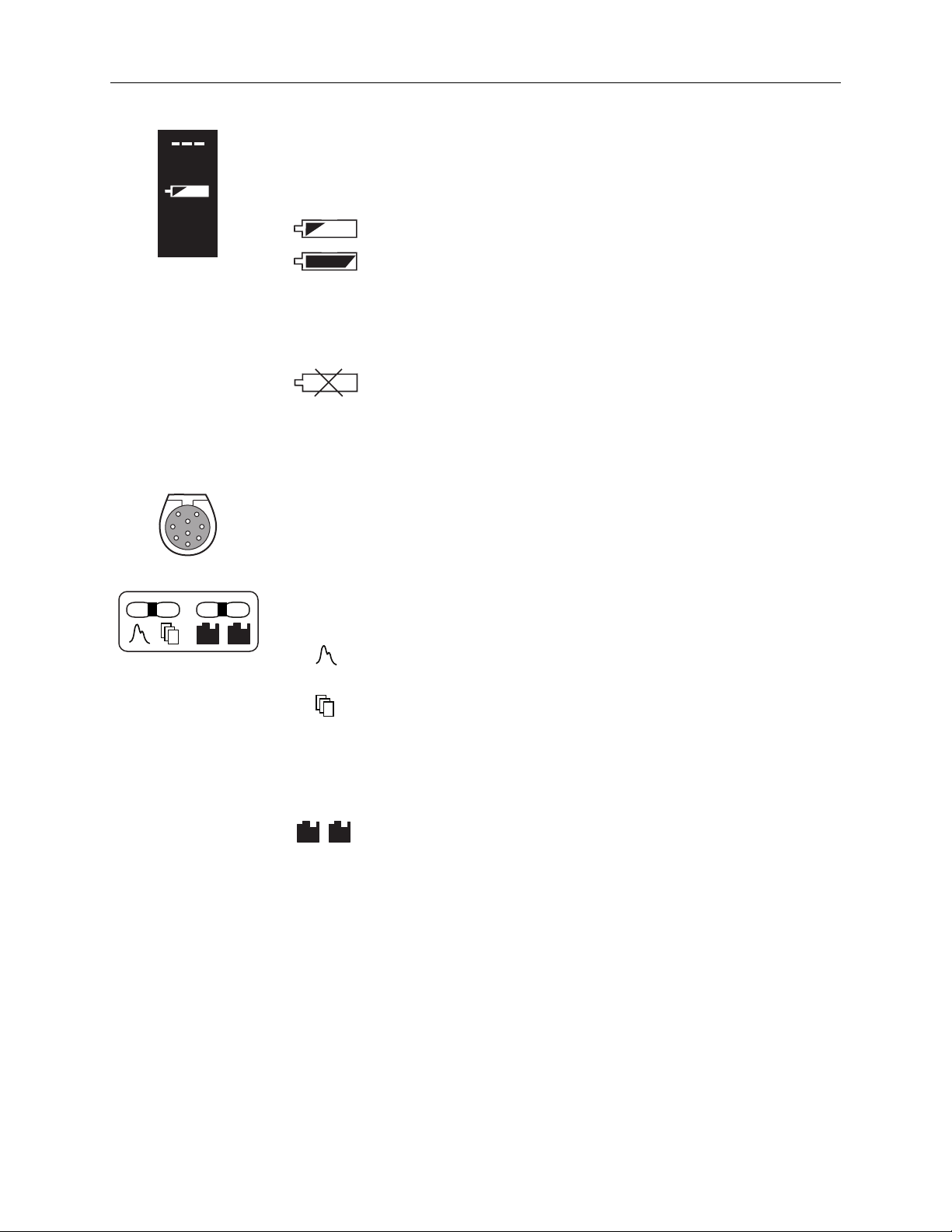
Battery operation
The oximeter runs for at least five and one-half hours on a new, fully charged
battery (somewhat less if the 3900P is printing) at normal operating
temperatures. LOW BATTERY appears when between 5 and 15 minutes of
battery operation time remain. Plug the monitor into AC power to continue
monitoring and recharge the battery. The unit will operate with a dead or
defective battery when it is connected to the AC power supply.
When the CONNECT UNIT TO LINE POWER message appears, you must
immediately plug the oximeter into the AC power supply or the unit turns
itself off after 10 seconds.
1-9
Page 20
3900/3900P User’s Manual
85
130
40
8 Carrying handle
9 Sensor connector
When operating on battery power, an icon appears between the two pairs of
alarm limit values on the right side of the LCD. (On Japanese menu screens,
the icon appears at the upper right beside the first menu option.) This icon
indicates the battery condition as follows:
Charged/not low
Low
If the all mute condition exists, the display of this icon alternates with the
display of the all mute icon.
This icon appears on the status screen:
Depleted, not installed, or defective
The lower front portion of the oximeter’s case is designed to be a carrying
handle for ease of moving the unit from one place to another.
The sensors for this oximeter plug into this nine-contact connector. Use only
OxyTip+ sensors compatible with this oximeter (see Parts list in
chapter 6).
SpO
10 Screen option buttons
PI
2
r
These buttons access the following features:
Press this button to return to the plethysmographic waveform
when you are at any other screen.
Press this button to view the main MENU. This menu provides
options for entering custom patient labels for individual data
records, for defining certain parameters, and for setting the
current date and time. This menu also provides access to the
modem features if a modem is installed. See Menu button in
chapter 2 for detailed information.
SpO
PI
2
r
Press the desired button to display SpO2 or PIr pulsatile value
trend on the screen. See Trend options in chapter 2 for detailed
information.
1-10
Page 21

1/Overview
♥
+
–
+
–
11 Pulse beep volume button
This button adjusts the volume level for the pulse indicator in incremental
steps from OFF to level 5. The power-on default is 2 if SAVE LIMITS is set to
NO (see SETTINGS in chapter 2).
Press the + side of the button to increase the volume or the – side to decrease
it; you will hear the volume level as you press the button. As you press one of
these buttons, the values do not cycle through the available settings; e.g., when
you reach 5, the value does not cycle (or wrap) to OFF and vice versa.
As you adjust the volume, the volume setting is shown in the message area
above the waveform.
NOTE: The pitch of the pulse tone changes as the SpO2 value increases or
decreases—the higher the SpO2 value, the higher the pitch of the pulse tone.
12 Alarm volume button
This button adjusts the audible alarm volume level in incremental steps from
1 to 5. You cannot set the alarm volume to OFF. The power-on default is 3 if
SAVE LIMITS is set to NO (see SETTINGS in chapter 2).
Press the + side of the button to increase the alarm volume or the – side to
decrease it; you will hear the volume level as you press the button. As you
press one of these buttons, the values do not cycle through the available
settings; e.g., when you reach 5, the value does not cycle (or wrap) to 1 and
vice versa.
As you adjust the volume, the volume setting is shown in the message area
above the waveform.
13 Printer
Monitoring data, current or trend, SpO2 or PIr pulsatile value, can be printed
on the 3900P printer. See chapter 4 for specific operating instructions.
1-11
Page 22
3900/3900P User’s Manual
t
Rear panel
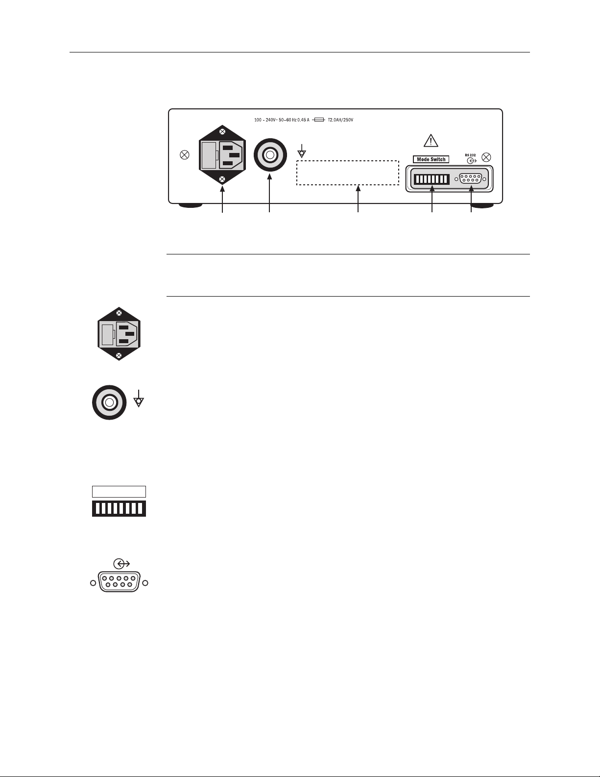
Figure 1-5. 3900/3900P Pulse Oximeter rear panel
WARNING: Electrical shock hazard. Because the unit is not grounded when it is operating on
battery power, do not connect any equipment to the RS-232 connector on the rear panel
unless the unit is connected to the AC power supply.
1 Power entry module
12 3 45
This module contains
• Fuses
• Power connector for the power cord that connects the oximeter to the
AC power supply for continuous operation and/or battery recharging.
Mode Switch
RS 232
2 Equipotential ground connector
In locations where this type of ground is required, connect your grounding
system here.
3 Product information label
Refer to Compliance with standards in chapter 7 for definitions of symbols tha
indicate compliance with standards set by regulatory agencies.
4 Mode Switch
This symbol identifies the two-position switches that set the display language,
the averaging mode, the display of the PIr pulsatile value, and the EMI line
frequency. See chapter 2 for instructions.
5 RS-232 serial/analog connector
This 9-pin connector provides:
• Serial information on SpO2, pulse rate, PIr pulsatile value, alarm limit
violations, and alarm messages with a time stamp and custom patient
label. The connector is compatible with most serial communication
devices; see Appendix B for instructions.
• Analog information on SpO2 and pulse rate waveform. Using the Datex-
Ohmeda modem/analog cable, the monitor can output data to a chart
recorder or polysomnography machine; see Appendix B for instructions.
• Serial information through a modem, using the Datex-Ohmeda
modem/analog cable. Data can be output to a fax machine or computer.
For details, see chapter 5.
1-12
Page 23

Precautions
Warnings
1/Overview
Two types of precautions appear in this manual: warnings and cautions.
• A WARNING indicates the possibility of injury to the patient or operator.
• A CAUTION indicates a condition that may lead to equipment damage or
malfunction.
NOTE: If you connect a modem, refer to the precautions contained in the
instructions you received with your modem.
Failure of operation
If the oximeter fails any part of the checkout procedures or current leakage test,
remove it from operation until qualified service personnel have corrected the
situation.
It is possible for any device to malfunction; therefore, always verify unusual data
by performing a formal patient assessment.
Data validity
Conditions that may cause inaccurate readings and impact alarms include
interfering substances, excessive ambient light, electrical interference, excessive
motion, low perfusion, low signal strength, incorrect sensor placement, poor sensor
fit, and movement of the sensor on the patient.
To prevent erroneous readings, do not use an inflated blood pressure cuff or
arterial blood pressure measurement device on the same limb as the oximeter
sensor.
Explosion hazard
Do not use the monitor in the presence of any flammable anesthetic mixture.
Electrical shock hazard
Do not remove the monitor cover. An operator may only perform maintenance
procedures specifically described in this manual. Refer servicing to qualified
service personnel trained in the repair of this equipment.
Measure the oximeter’s leakage current whenever an external device is connected
to the RS-232 port. Forward and reverse polarity = 100 microamperes maximum.
This equipment must be properly grounded.
• Electrical safety specifications (e.g., current leakage and ground resistance)
can be assured only when the monitor is connected to a three-wire, grounded
receptacle without the use of extension cords or adapters.
• If there is any doubt about the integrity of the AC power supply protective
earth conductor, operate the monitor on internal battery power.
• Because the unit is not grounded when it is operating on battery power, do not
connect any equipment to the RS-232 connector on the rear panel unless the
unit is connected to the AC power supply.
1-13
Page 24
3900/3900P User’s Manual
Electrical shock and flammability hazard
Before cleaning or servicing the oximeter, always turn it off and disconnect the
power cord from the AC power supply.
Patient safety
The correct use of the oximeter is to measure only arterial oxygen saturation
(SpO2), pulse rate, and Relative Perfusion Index pulsatile value.
• A pulse oximeter does not measure respiration and should never be used as a
• A pulse oximeter may be used during sleep studies of adults only to gather
This device is not intended for use in a magnetic resonance imaging (MRI)
environment.
Patient safety (sensors)
Patient conditions (such as reddening, blistering, skin discoloration, ischemic skin
necrosis, and skin erosion) may warrant changing the sensor site frequently or
using a different style of sensor.
substitute for an apnea monitor or as the primary monitor for infants being
monitored for apnea.
information regarding SpO2, pulse rate, and PIr pulsatile value.
To prevent patient injury or equipment damage, use only OxyTip+ oximeter
sensors approved for use with this oximeter. For complete information about the
safe and appropriate use of a sensor, consult the instructions for that sensor.
Discard a damaged sensor immediately. Do not repair a damaged sensor or use a
sensor repaired by others.
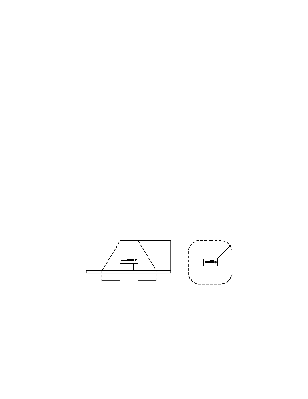
Patient safety (modem)
Do not use the modem within the patient environment defined below:
)
t
f
2
.
8
(
m
5
.
2
1.5 m (5 ft)1.5 m (5 ft)
)
t
f
5
(
m
5
.
1
Do not connect the modem to the oximeter when the oximeter is operating on
battery power.
RS-232 system interconnection
Accessory equipment connected to the RS-232 serial/analog connector must be
certified according to the current version of the respective IEC/EN standards
(e.g., IEC 60950 for data processing equipment and IEC/EN 60601-1 for medical
equipment). All configurations shall also comply with IEC/EN 60601-1-1. Anyone
who connects additional equipment to the RS-232 serial/analog connector
configures a medical system, and is therefore responsible that the system complies
with the requirements of IEC/EN 60601-1-1. If in doubt, call your local authorized
1-14
Page 25

Cautions
1/Overview
service office. The 3900/3900P is referred to as an IEC/EN 60601/F device
in the summary of situations table contained in IEC/EN 60601-1-1.
Handle the monitor with care
Improper handling can cause damage or inaccurate results.
Cleaning
Do not autoclave, pressure sterilize, or gas sterilize this oximeter.
Use cleaning solution sparingly. Do not soak or immerse the monitor in liquid.
Excessive solution can flow into the monitor and damage internal components.
When cleaning the display area, do not use abrasive cleaning compounds or other
materials that could damage the screen.
Do not use petroleum-based solutions, acetone solutions, or other harsh solvents to
clean the oximeter. These substances may damage the oximeter and cause a
malfunction.
To prevent damage to the 3900P printer, do not allow any cleaning solution to get
into the printer mechanism.
Sensors
Do not apply tension to the sensor cable; sensor damage may result.
Battery
The 3900/3900P internal battery, containing lead and acid, is a hazardous waste.
Dispose of the battery through an approved hazardous materials disposal facility
or return it to Datex-Ohmeda for disposal.
To prevent damage to the lead-acid battery, do not turn the monitor on after the
LOW BATTERY message appears without first plugging it in to the AC power
supply.
Printer
To avoid damage to the print head, do not operate the printer without paper.
Paper purchased from Datex-Ohmeda has red edges when the paper roll is
nearing depletion.
To avoid damage to the printer, never pull the paper backward through the
printer mechanism.
To avoid damaging the printhead mechanism, discharge any possible static
electricity from your person before removing the paper feed cover on the printer.
Disposal
Dispose of this medical device and its packing materials according to local
requirements.
1-15
Page 26

3900/3900P User’s Manual
1-16
Page 27

2/Setup and Operations
This chapter provides the following information and instructions:
• Powering the oximeter.
• Selecting the language, averaging mode, PIr pulsatile value display, and EMI
(electromagnetic interference) line frequency.
• Checkout procedure—to determine that all functions of the 3900/3900P
oximeter are working properly.
• Signal and data validity guidelines.
• Menu options.
• Trend data options; SpO2 and PIr pulsatile value.
• Lock-buttons procedure—to prevent changes to the monitor’s settings.
To operate the 3900/3900P oximeter effectively, you must
• Know how the oximeter derives its readings (see Principles of operation in
chapter 1).
• Be familiar with its controls and components (see chapter 1).
• Understand its messages (see chapter 3).
Powering the oximeter
The 3900/3900P pulse oximeter is designed to operate on battery power and on all
commonly available voltage supplies. Your oximeter was shipped with the correct
power cord for your local AC power supply. Any hospital-grade power cord,
however, with the female connector end that fits into the power module (IEC-320
type) on the 3900/3900P can be used; the male connector that plugs into the
grounded “wall” outlet may be whatever is needed locally. The oximeter accepts a
range of AC mains power; see chapter 7 for details.
To protect data validity in cases of possible electromagnetic interference, make
sure the EMI line frequency mode switch is set to the same frequency as your
local AC power supply before using the unit for patient monitoring; see EMI line
frequency under Mode switch settings later in this chapter.
A battery does not need to be installed for the oximeter to operate on the AC
power supply.
2-1
Page 28

3900/3900P User’s Manual
Setup
Factory settings
When you turn on the oximeter, the following settings are in effect and remain in
operation until you change them.
Before powering on the oximeter
Use the mode switches in the oximeter’s rear panel to set the language, averaging
mode, PIr pulsatile value display, and EMI line frequency.
Parameter Factory Setting Range
Language English Danish, Dutch, English, Finnish, French,
German, Italian, Japanese, Norwegian,
Polish, Portuguese, Spanish, or Swedish
Averaging mode
PIr pulsatile value display Yes Yes (display PIr value) or No
EMI line frequency 60 Hz 50 Hz or 60 Hz
Long / TruTrak+
(12 seconds)
Long / TruTrak+ (12 seconds),
Medium (6 seconds), or Short (3 seconds)
After powering on the oximeter
Changes you make to the parameters shown below take effect immediately.
Parameter Factory Setting Range
High SpO2 limit OFF
(appears as: – – –)
Low SpO2 limit 85% 50% to 100% or OFF
High pulse rate 130 bpm* 30 to 235 bpm or OFF
Low pulse rate 40 bpm 30 to 235 bpm or OFF
Alarm volume 3 1 to 5
Pulse volume 2 1 to 5 or OFF
Save limits NO YES or NO
All mute YES YES (enabled) or NO (disabled)
50% to 100% or OFF
2-2
Serial transmission baud rate 9600 9600, 19.2K, 38.4K, or 57.6K
Data output mode
(printer and modem)
Data output resolution 6-second interval 6- or 30-second intervals
Print contrast 5 1 through 10
Date format DD/MM/YY MM/DD/YY, DD/MM/YY, YY/MM/DD
* bpm= beats-per-minute
SpO
2
SpO2 or PI
r
Page 29
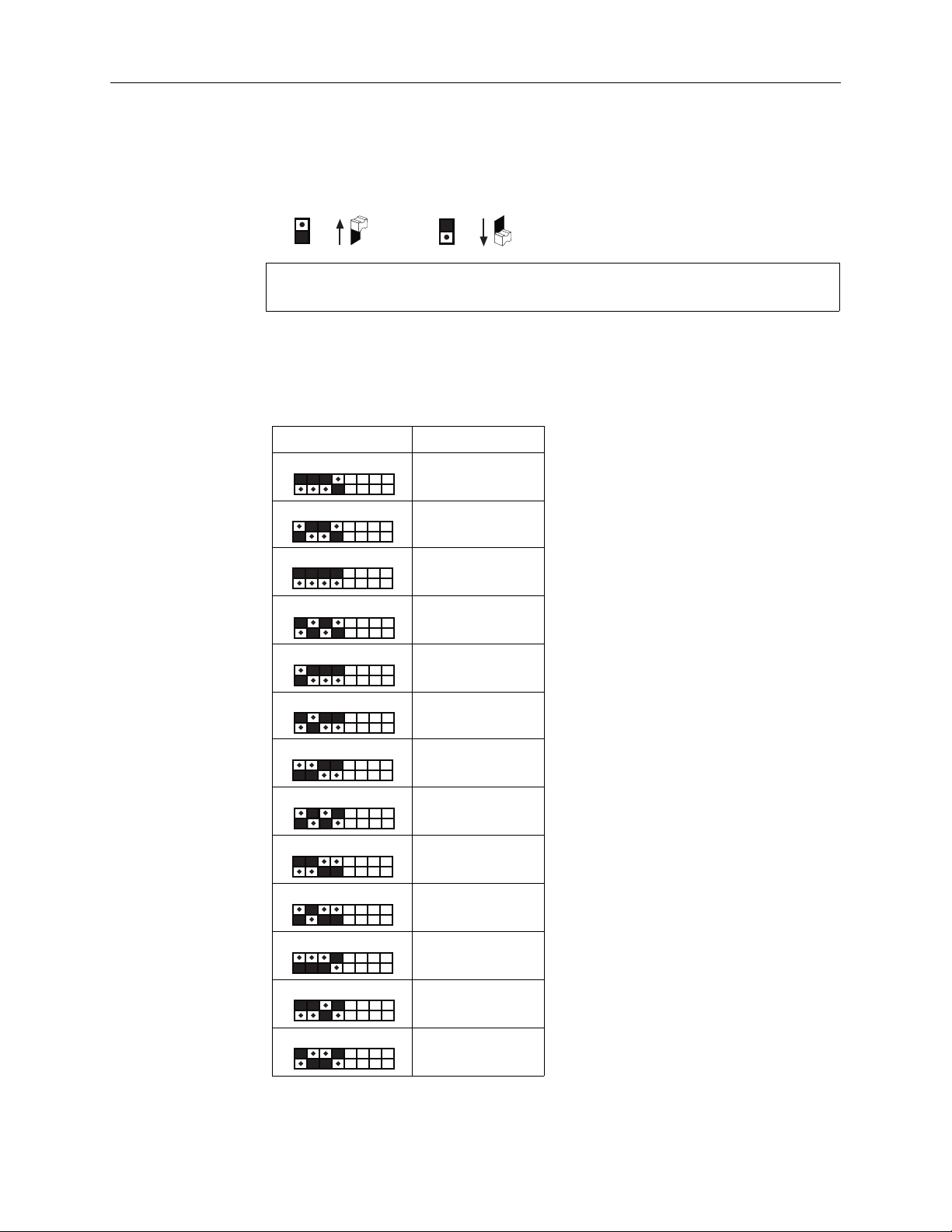
Mode switch settings
A bank of eight numbered, two-position switches is accessed through the rear
panel. The up position is ON and the down position is OFF.
2/Setup and Operations
=
=
Important: If you change the switch settings while the oximeter is on, the new
settings do not take effect until you power off, then on again.
Language selection
Switches 1, 2, 3, and 4 set the language used for the display, 3900P printer output,
and data transmitted through the RS-232 port. (For Japanese, printer output and
data transmissions are in English only.)
Switches Language
1234
Danish
1234
Dutch
1234
English
1234
Finnish
1234
French
1234
1234
1234
1234
1234
1234
1234
1234
German
Italian
Japanese
Norwegian
Polish
Portuguese
Spanish
Swedish
2-3
Page 30
3900/3900P User’s Manual
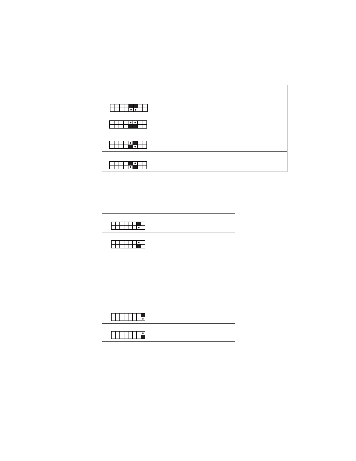
Averaging mode
Switches 5 and 6 set the averaging mode. The averaging mode selects the time
period of data used to calculate a weighted average SpO2 value to be displayed by
the oximeter.
Switches SpO2 and Pulse Rate Averaging
56
56
56
56
Long (12 seconds) Yes (enabled)
Medium (6 seconds) No
Short (3 seconds) No
PIr pulsatile value display
Switch 7 sets the display of the PIr pulsatile value.
Switch Display PIr value
7
Yes
7
No
TruTrak+
EMI line frequency
Switch 8 sets the EMI line frequency. To optimize EMI (electromagnetic
interference) immunity, make sure switch 8 is in the correct position for the AC
power line frequency in use.
Switch EMI Line Frequency
8
60 Hz
8
50 Hz
2-4
Page 31

Checkout procedure
WARNING: Failure of operation. If the oximeter fails any part of the checkout procedures or
current leakage tests, remove it from operation until qualified service personnel have
corrected the situation.
WARNING: Explosion hazard. Do not use the monitor in the presence of any flammable
anesthetic mixture.
WARNING: Electrical shock hazard. This equipment must be properly grounded.
• Electrical safety specifications (e.g., current leakage and ground resistance) can be
assured only when the monitor is connected to a three-wire, grounded receptacle without
the use of extension cords or adapters.
• If there is any doubt about the integrity of the AC power supply protective earth conductor,
operate the monitor on internal battery power.
• Because the unit is not grounded when it is operating on battery power, do not connect
any equipment to the RS-232 connector on the rear panel unless the unit is connected to
the AC power supply.
2/Setup and Operations
If you plan to send serial or analog data to another device, make sure the device is
connected to the rear panel connector before you power on the monitor and
make sure the monitor is connected to the AC power supply.
Important: For TruTrak+ performance, the averaging mode must be set to Long.
1. Inspect the oximeter case for damage. Make sure the display windows are
clean.
WARNING: Sensors
• Discard a damaged sensor immediately. Do not repair a damaged sensor or use a
sensor repaired by others.
• To prevent patient injury or equipment damage, use only Datex-Ohmeda oximeter
sensors approved for use with this oximeter. For complete information about the safe
and appropriate use of a sensor, consult the instructions for that sensor.
CAUTION: Do not apply tension to the sensor cable; sensor damage may result.
2. Check that the sensor is a compatible model before connecting it to the
oximeter. Only Datex-Ohmeda OxyTip+ sensors can be used with this monitor.
If you’re using a reusable sensor, make sure it opens and closes smoothly.
Remove substances that may interfere with the transmission of light between
the sensor's light source and detector.
3. Connect the sensor cable to the sensor connector on the monitor. Make sure
the connection is firm and that the cable is not twisted, sliced, or frayed.
4. Attach the sensor to a finger or an ear, depending on the sensor you are using.
2-5
Page 32

3900/3900P User’s Manual
5. To turn on the oximeter, press the power button.
The first screen shows the Datex-Ohmeda logo and the model name
(Model 3900 or Model 3900P).
Important: If the low SpO2 alarm limit was saved at a limit lower than 80%
(or at OFF), you will be alerted by a screen message that shows the current
low SpO2 alarm limit and alarm volume level:
LIMITS SAVED
LOW SpO2 = 75%
The next screen shows the averaging mode in effect, the SpO2 calibration
mode, the progress of the self-test, and the status of the battery charge.
Averaging Mode: Long
SpO2 Calibration: Functional
Self-test in progress …
(indicates battery-charge status)
Below the bar graph, the version number of the unit’s system and oximetry
software appears as Version X.XXX/YY.YYY, where X’s represent the system
software version and Y’s the oximetry software version.
Diagnostic self-test
During this time the system performs a diagnostic self-test (electronics,
battery status, analog signal path integrity, calibration check) and sets the
default parameters. This self-test takes approximately 10 seconds.
• A start-up tone sequence tests the audio circuit; all display LEDs and
the LCD backlight are illuminated, then blanked.
• The alarm LED toggles between red and yellow while a numeric
countdown from 9 to 0 occurs on each seven-segment LED display
ending with a decimal point.
• A battery icon is displayed to indicate the battery condition as either
charged, depleted, or defective/missing (see chapter 3).
Upon successful completion of all diagnostic self-tests, the unit is
considered to be in calibration and begins normal operation. This message
is displayed:
Test passed. In calibration.
2-6
If the unit does not pass the self-test, an error message is displayed and the
unit is inoperable.
Page 33

2/Setup and Operations
6. On the displays, verify
• The high and low alarm limits for SpO2 and pulse rate.
• Dashes (– – –) appear for any limit set to OFF.
• The readings for SpO
Dashes may appear on the display until the SpO
pulsatile value readings have stabilized (approximately 12 seconds).
NOTE: The audible alarm feature for all alarm conditions is silenced for the first
two minutes after powering on.
7. If two minutes have elapsed since you powered on, verify that the patient
alarms are functional by setting the high and low SpO2 and pulse rate alarm
limits beyond the current readings. Make sure
• An alarm tone sounds.
• The violated alarm limit and reading flash on the display.
• Depending on the priority of the alarm, a red or yellow alarm light flashes.
8. Verify the sensor alarms are functional by removing the sensor from the
sensor site. Make sure
• SENSOR OFF or CHECK SENSOR SITE appears in the message area of
the graphic display.
• The alarm tone sounds; the alarm light flashes.
, pulse rate, and PIr pulsatile value.
2
, pulse rate, and PI
2
r
9. Unplug the sensor from the oximeter. Make sure
• NO SENSOR appears.
• The alarm tone sounds; the alarm light flashes.
10. Press the alarm silence button. Make sure
• The alarm tone ceases.
• The alarm light is steady.
11. To begin patient monitoring, connect the desired Datex-Ohmeda sensor to the
oximeter. Attach that sensor to the patient.
To verify the sensor is on correctly and that the data are verifiable, see Signal and
data validity in this chapter.
WARNING: Patient safety. Patient conditions (such as reddening, blistering, skin discoloration,
ischemic skin necrosis, and skin erosion) may warrant changing the sensor site frequently or
using a different style of sensor.
2-7
Page 34

3900/3900P User’s Manual
Signal and data validity
Plethysmographic waveform
The oximeter’s PerfTrak waveform display provides a visual indicator of the
validity of the values that appear on the display. The waveform is scaled to
correspond to the perfusion level or strength of the signal being received at the
patient monitoring site.
NOTE: When a message appears in the upper portion of the LCD, the waveform
rectangle becomes smaller but the correspondence between signal strength and
waveform height is maintained.
You should be able to easily identify three complete passes of the
plethysmographic waveform. Although the waveform shape may vary from patient
to patient, under normal conditions it corresponds to the arterial pressure
waveform.
Use Figures 2-1 (adult) and 2-2 (neonate) as guidelines to determine a sensor
placement that generates the fewest noise spikes.
Figure 2-1. Typical adult plethysmographic waveform
Figure 2-2. Typical neonate plethysmographic waveform
The “typical” neonate waveform differs from that of an adult, including the
absence of a dicrotic notch (a notch on the descending limb of the normal arterial
pulse tracing that corresponds to aortic valve closure).
Low perfusion
As the perfusion at the patient monitoring site decreases, so will the height of the
waveform. (The PIr pulsatile value is a numeric representation of the relative
height of the waveform.)
The height will decrease to the point where the signal quality becomes too small
or too poor for accurate, reliable readings. At that point, the message CHECK
SENSOR SITE appears in the message area and an alarm is generated. The
waveform will be similar to Figure 2-3.
2-8
Page 35

CHECK SENSOR SITE
Figure 2-3. Low perfusion waveform
Signal noise
The following conditions can cause noisy waveforms:
• Poor sensor placement.
• Motion at the sensor site.
• Electrical interference.
2/Setup and Operations
Figure 2-4. Noisy plethysmographic waveform
If three easily identifiable passes of a “typical” waveform do not occur,
• Make sure the sensor’s detector is flush with the sensor site (for sensor
application, see the instructions for the sensor you are using).
• Make sure the light source and detector are directly opposite each other.
• Select a site where the distance between the light source and the detector is less.
• Make sure the patient site is stable; minimize movement of the sensor site.
• Massage the sensor site with a 70% isopropyl alcohol pad or rubefacient cream
(10-30% methyl salicylate and 2-10% menthol) for 20-30 seconds. Strong
vasodilator creams, such as nitroglycerin paste, are not recommended.
• If possible, remove electrical noise sources such as electrosurgery or
electrical/electronic devices (e.g., fans). If these solutions are not possible,
operate the oximeter on battery power, or try plugging the oximeter into a
different electrical outlet.
• If artificial nails or excessive fingernail polish are present, select another site
or remove the polish/artificial nails.
2-9
Page 36

3900/3900P User’s Manual
Numeric display
SpO
2
Stability of the SpO2 readings is a good indicator of signal validity. Although
“stability” is a relative term, with practice you’ll get a good feeling for changes that
are artifactual or physiological and the speed of each. The stability of the readings
over time is affected by which averaging mode you're using. In Long / TruTrak+
mode (12-second averaging), the readings tend to be more stable because the
signal is averaged over a longer period of time than the Short (3 seconds) or
Medium (6 seconds) modes.
Too great a distance between the sensor emitter and detector can reduce signal
strength and result in a poor signal. When the value is too low, the message
CHECK SENSOR SITE may appear to alert you that the SpO2 value may not be
accurate. Perfuse the sensor site or relocate the sensor to a site with higher blood
flow.
Pulse rate
Compare the displayed pulse rate to the patient’s palpated pulse rate. If the unit’s
rate varies significantly from the palpated rate, the data may be less accurate due
to motion artifact or other noise.
A cough or other hemodynamic pressure disturbance can disrupt the pulse rate,
which is determined from the plethysmographic waveform. The time span
between the waveform’s peaks determines the pulse rate. The unit uses the same
averaging mode (long, medium, or short) as that selected for SpO2.
PIr pulsatile value
The PIr pulsatile value is a measurement of the strength of the photoplethysmographic signal read by the oximeter. The greater the number, the greater the
pulsatility and the validity of the SpO2 and pulse rate data. This value is useful
when determining that the sensor is correctly attached and that the data are
verifiable. It is also an indicator of relative perfusion at the sensor site.
2-10
Page 37

Waveform screen button
When you are viewing some other display or screen, press this button to return to
the waveform screen. You can also use this button to exit from a menu or option
screen to prevent changes you have made from being confirmed.
Menu button
This button accesses the main menu, which has the following options:
2/Setup and Operations
MENU
MODEM
LABELS
SpO
— +
2
SETTINGS
DATE
— +
Figure 2-5. Main menu
Important: If an alarm occurs while you are viewing any screen other than the
waveform screen or PIr pulsatile value trend screen, the display immediately
reverts to the waveform screen and the alarm message appears above a reduced
waveform graphic.
If you have not confirmed the selection(s) you made (by selecting ), the
changes are not in effect. You must access the option screen again and re-enter
the changes after you have attended to the alarm condition (except when
entering label text, see LABELS in this chapter).
If you are viewing the waveform screen while transmitting data, you can check
the status of the transmission by pressing the Menu button. The screen that
appears also contains an option to cancel the transmission. After viewing the
status, press the Waveform button to return to the waveform screen.
Main menu function key buttons
When this screen and subsequent screens accessed from this menu are displayed,
the four alarm limits buttons to the right of the screen become function keys—their
function changes to permit selection of the menu item to the left of the key. For
example, in Figure 2-5 above,
• Press the top button (high SpO2 alarm limit) to select MODEM.
• Press the second button (low SpO2 alarm limit) to select LABELS.
• Press the third button (high pulse rate alarm limit) to select SETTINGS.
• Press the bottom button (low pulse rate alarm limit) to select DATE.
2-11
Page 38

3900/3900P User’s Manual
LABELS
This main menu option accesses the screen where you can enter custom patient
labels—alphanumeric characters that help identify patients and their associated
data. There are four lines available to enter labels.
A label is included in data transmissions and printouts. If you use the modem or
fax function, we recommend that you enter a label to identify the patient. If you
do not enter a label, the report will contain four blank lines, on which you can
write the patient’s name. If you do not want a label, clear all text from the LABELS
screen.
If a custom patient label is desired, the label text mmmmuuuusssstttt be entered before
monitoring begins. Once the label is entered into memory, aaaallllllll subsequent patient
data stored to memory is associated with that label (unless it is cleared or
changed). If a new label is not entered prior to monitoring, the data will be
associated with the previous label.
Once the label is input on the LABELS screen, you must press
label to trend memory. If you fail to press , the label is simply present on the
LABELS screen and is not stored in trend memory.
Labels are stored in memory along with their associated SpO2 and PIr pulsatile
value data. A new record is created in memory each time a new label is stored to
memory, the oximeter is turned off, or the date and/or time are changed. When a
report is generated, a page break and new headings print for each new record.
The labels you create remain in trend memory until you clear the trend data or
until all the patient data associated with the label are overwritten; i.e., when 24
hours of data are already stored in memory and the oldest records are overwritten
as additional data are recorded and stored to memory.
If labels and associated data are cleared from trend memory but label text is not
cleared from the LABELS screen when you begin monitoring again, any text on
the LABELS screen is used to identify the new record.
to store the
Summary: custom patient labels
• Labels are used to identify patients.
• Labels are included in all printed reports (3900P) and data transmissions.
• Labels must be entered prior to monitoring patients.
• Labels create new records in trend memory.
• Labels are cleared from the LABELS screen and/or from trend memory by
using the CLEAR button on the LABELS screen (Figure 2-6) and the trend
screens (Figure 2-9).
2-12
Page 39

2/Setup and Operations
LABELS
— +
SpO
H
_GONZALES _ _ _ _ _
_ _ _ _ _ _ _ _ _ _ _
_
O
O
DR_CASEY _ _ _ _ _ _
O
GENERAL
Figure 2-6. LABELS screen
_ _ _ _ _ _ _
– / +
CLEAR
2
— +
Select field function keys
Press the left half of the button (–) to move the cursor (a rectangle) left ( ) or press
the right half (+) to move the cursor right ( ) one character field from its current
position.
• If the cursor is on the first character of the first line and you press , the
cursor moves to the last character of the last line.
• If the cursor is on the last character of the last line and you press , the cursor
moves to the first character of the first line.
When moving the cursor to the right and it reaches the end of a line, it moves
down to the beginning of the next line. When moving the cursor left and it
reaches the beginning of a line, it moves up to the end of the previous line.
Hold down the desired side of the button to move more quickly through the fields;
release it when you reach the field you want to change.
When the screen is first accessed, the cursor is on the first character field in the
first line.
– / + Select character function keys
Use this button to move through the characters available for the language you set.
For English and Japanese, this set is
A B C D E F G H I J K L M N O P Q R S T U V W X Y Z
0 1 2 3 4 5 6 7 8 9
/ & ’ – , (comma) . (period) [space]
Press the left half (–) to move to the next character in descending order. Press the
right half (+) to move to the next character in ascending order. Hold down the
desired side of the button to move more quickly to the character you want and
then release it.
Function key
After entering or clearing label characters, press this function key to store your
changes to trend memory and to exit the screen. This begins a new data record.
At this point, label screen text is stored in memory and any monitoring that occurs
after this time is stored with the new label. The lines of information you entered
remain on the screen until you clear them from this screen or enter and confirm
new label information in their place.
2-13
Page 40

3900/3900P User’s Manual
NOTE: If an alarm occurs while you are entering label characters, the waveform
screen appears with the alarm message. After you have attended to the alarm
condition, return to the LABELS screen. The characters you had entered prior to
the alarm are still there but they are not yet saved in memory as the label for the
current data record. You do not have to reenter them, but you do need to
complete the label information and then press
CLEAR
Select CLEAR to access the clear patient data screen options:
Option Action
CLEAR LABELS Clears label text from unlocked lines on the LABELS
CLEAR TREND Clears all SpO2 and PIr trend data in memory, including
CLEAR BOTH Clears label text from unlocked lines on the LABELS
to save the label to memory.
screen.
the labels in memory associated with that data.
screen and clears all stored trend data, including labels
in memory associated with that data.
After choosing an option, you can confirm your choice by selecting YES or NO.
• If you select YES, a high beep tone sounds. If you select NO, a low beep tone
sounds. A message indicating that the labels, trends, or both have or have not
been cleared (depending on your selection) is displayed for three seconds.
• If you do not select YES or NO within 10 seconds, a low beep tone sounds and
the previous screen is displayed.
NOTE: Text on the LABELS screen that is not erased will be used for the next
data record.
Locking label lines
Line 1 remains in memory until you change it (or clear it) and press . This
line has 13 character fields and it cannot be locked.
Lines 2, 3, and 4 can each be locked to retain their information until you unlock
the lines and change the text or use CLEAR to remove it. These lines have 12
character fields each. The first character field on each line is reserved for a lock or
unlock symbol. With the cursor on the symbol, use the –/+ function keys to switch
between the symbols and thereby lock or unlock that line. When a line is locked,
it is not erased from the screen when you select CLEAR.
2-14
Page 41

SETTINGS
2/Setup and Operations
Select SETTINGS from the main menu to access the first of two settings screens.
These settings are retained in memory and are not cleared when you clear trend
data or power off the monitor (as long as the internal battery is charged).
SAVE LIMITS: NO
— +
SpO
ALL MUTE: YES
– / +
2
BAUD RATE: 9600
— +
ANALOG: 0.0V
— +
MODE: SpO
2
– / +
SpO
2
OUTPUT: 6 SEC
CONTRAST: 5
Figure 2-7. Settings screen options
Press the function key to switch from screen to screen.
Press the or function key to move the cursor (a rectangle) down or up,
respectively, through the options.
Press the – or + function key to cycle through the settings available for the option
you have selected.
Press the function key to record your selections on these screens and return
to the MENU screen.
— +
SAVE LIMITS
Use this option to save the high and low SpO2 and pulse rate alarm limits and the
pulse beep and alarm volumes you have set so they are retained when you power
off. The cursor is automatically on the SAVE LIMITS option field when the settings
screen appears. The options are NO and YES. To save the alarm limits settings for
use the next time the unit is powered on, select YES.
NOTE:
• Whenever a low SpO2 alarm limit below 80% (or OFF) is set and then saved
to memory, a screen appears during the power-up sequence to alert the
operator. The screen shows the saved limit for the low SpO2 alarm and the
saved alarm volume setting.
• If your patients are neonates, use this option to save the appropriate high and
low alarm limits between power cycles.
2-15
Page 42

3900/3900P User’s Manual
ALL MUTE
Use this option to enable (YES) or disable (NO) the ability to mute audible alarms.
• When enabled (YES), you can press the alarm silence button three times
• When disabled (NO), you cannot silence the alarms continuously.
BAUD RATE
Use this option to select the appropriate baud rate when sending serial data
directly to a computer; see Appendix B for more information. The options are
9600, 19.2K, 38.4K, and 57.6K.
ANALOG
Use this option to calibrate an analog device (chart recorder, polysomnography
machine, etc.). The options are 0.0V, 0.5V, and 1.0V. See Appendix B for more
detailed information.
MODE
Use this option to select between SpO2 or PIr pulsatile value modes. The mode
you select determines the data and format used for printer and modem output.
The mode also determines whether an alarm condition will cause a trend display
screen to revert to the waveform screen.
(within 3 seconds) and silence the alarms until you press the alarm silence
button again (or the unit is powered off).
OUTPUT
Use this option to select 6-second or 30-second interval formats when printing data.
6 sec (second) output specifies the following:
Trend data: every data point for SpO2 or PIr data.
Current data: lowest data point for SpO2 and the average PIr value for that
6 seconds.
30 sec (second) output specifies the following for trend data:
SpO2: the lowest data point out of every 5.
PIr: the average of 5 data points.
CONTRAST (3900P printer only)
If you have the 3900P, this option allows you to adjust the print quality of the
printer output. The options are 1, (lightest print) through 10 (darkest print). Press
the – or + function key to decrease or increase, respectively, the print quality.
2-16
Page 43

Date and time
2/Setup and Operations
Select DATE from the main menu to set the current date and time. This
information appears with data records in trend memory and on all printed or
transmitted data.
DATE/TIME
DD / MM / YY
– / +
SpO
— +
2
17 05 98
HH : MM
FORMAT
— +
13 05
Figure 2-8. DATE/TIME screen
The cursor automatically appears in the first date field. Use the or function
keys to position the cursor on the desired field. Use the – or + function keys to
decrease or increase, respectively, the numbers in the fields.
NOTE: To only view this screen without changing the settings, select DATE, view the
information, and then press the waveform button to exit the screen. Do not press
, or the time may be altered slightly.
Date
Use the FORMAT function key to select the order in which you would like the
date to appear.
DD/MM/YY
MM/DD/YY
YY/MM/DD
You cannot set the last date for a month higher than the number of days in that
month. The values you can enter for the date are as follows:
Dates: 01 through 28, 29, 30, 31 (depending on month and year)
Months: 01 through 12
Years: 00 through 99
NOTE: If you need to set February 29 as the date in a leap year, specify the year
numbers first and the monitor will then accept 29 as the date.
Time
The time fields are always in 24-hours/minutes format: HH MM
The values you can enter are:
Hours: 00 through 23
Minutes: 00 through 59
To accept the values you have entered for the date and time, set the time, and
return to the main menu, select the function key.
2-17
Page 44

3900/3900P User’s Manual
Trend options
12
SpO
2
100
90
80
8
11:48:06 05-17-99
You may choose to view SpO2 data
3
56
4
94% - 96%
SpO
2
or PIr pulsatile value data
4
3
2
0.98 - 1.00
3.0
1
P I
2.49
r
P I
r
5
2.0
CLEAR
00:24
7
1.0
0.0
8
11:48:06 05-17-99
6
7
SpO2 trend PIr pulsatile value trend
Figure 2-9. Trend screens
1 The type of trend data being displayed appears here (SpO2 or PIr). In the PI
trend screen, the current PIr pulsatile value also appears here.
2 A heavy, dashed line indicates power to the monitor was turned off. All power-
off events are shown in the trend data.
3 The cursor is a dotted line in the middle of the screen.
4 The value for the data (or data value range) at the cursor appears here.
5 A gap in the trend indicates a period for which there was no data.
6 The most recent data are here, on the right side of the graph.
7 The time and date for the data at the cursor appear here.
8 SpO2: The bottom number on this scale adjusts automatically to show the
lowest value of the SpO2 data on the screen (rounded to a multiple of 10%).
The default is 80 to 100%. If, for example, a data point value in the trend is
78%, the scale adjusts to become 70 to 100%. The lowest scale value possible is
0 to 100%.
PIr: The top number of this scale adjusts automatically to show the range of
PIr pulsatile values. The default is 0.0 to 3.0. If, for example, a data point value
in the trend is 4.50, the scale adjusts to become 0.0 to 6.0. The highest scale
value possible is 9.99 on a scale of 0.0 to 10.0.
.
CLEAR
00:24
r
2-18
The default trend screen shows 24 minutes of data. If you select a different time
scale, that scale is in effect until you change it or power off; see Viewing time scale
for display.
Page 45

Trend function keys
Trend data scroll across the screen from right to left with the most recent data
record always appearing from the right. When viewing a trend screen, the alarm
limit buttons assume the following functions:
Scroll buttons
Press the side of the button that points to the side of the screen from which you
want data to appear: use to bring newer data in from the right (they scroll
across the screen to the left); use to bring older data onto the screen from the
left (they scroll across the screen to the right). These buttons scroll the data by one
pixel column until the end of the trend data is reached. You can hold down the
button to move through the data more quickly; you’ll hear a low beep when there
are no more data to view.
Shift buttons
These shift buttons scroll in the same manner as the scroll buttons, except that
they scroll by 25% of the displayed data until the end of the trend data is reached.
You can hold down the button to move through the data more quickly; you’ll hear
a low beep when there are no more data to view.
2/Setup and Operations
To scroll as quickly as possible through a large amount of data, select the longest
time scale possible (see Viewing time scale for display) and repeatedly press the
appropriate button ( to scroll to the newest data, or to scroll to the oldest
data) until you reach the data you want to view.
CLEAR
Select CLEAR to access the clear patient data screen options:
Option Action
CLEAR LABELS Clears label text from unlocked lines on the LABELS
screen.
CLEAR TREND Clears all SpO2 and PIr trend data in memory, including
the labels in memory associated with that data.
CLEAR BOTH Clears label text from unlocked lines on the LABELS
screen and clears all stored trend data, including labels
in memory associated with that data.
After choosing an option, you can confirm your choice by selecting YES or NO.
• If you select YES, a high beep tone sounds. If you select NO, a low beep tone
sounds. A message indicating that the labels, trends, or both have or have not
been cleared (depending on your selection) is displayed for three seconds.
• If you do not select YES or NO within 10 seconds, a low beep tone sounds and
the previous screen is displayed.
NOTE: Text on the LABELS screen that is not erased will be used for the next
data record. See LABELS earlier in this chapter.
2-19
Page 46

3900/3900P User’s Manual
Viewing time scale for display
You can select to view from 12 minutes to 24 hours of data on the screen; 24
minutes (00:24) is the default. When you change the time scale, that scale remains
in effect the next time you access the trend screen.
Press the left (-) or right (+) side of the function key to decrease or increase,
respectively, the viewing time scale. The available options are as follows:
At the shortest time scale (12 minutes), each pixel column on the trend graph
represents one six-second data point. A single numeric value appears to the left of
the cursor.
For longer time scales, each pixel column represents multiple data points. The
lowest and highest values for the range of data points at the cursor appear to the
left and right of the cursor line, respectively. When the cursor is on multiple data
points, the time and date of the oldest data appear at the bottom of the screen.
• If you change the time scale to be longer or shorter while viewing a column of
• If no valid data exist at a column, dashes represent “no value,” and the time
• All power-off cycles appear on the trend graph regardless of the time scale
00:12 or 00:24 minutes
01:00, 02:00, 06:00, 08:00, 12:00, 16:00, 20:00, or 24:00 hours
trend data, the time and date shown do not change.
and date are shown.
selected.
Trend data
The trend data are maintained in the monitor as long as the monitor’s battery is
connected and charged to minimum operating level.
The oximeter stores a maximum of 24 hours of trend data. The data are stored in
trend memory every six seconds and include the following:
• lowest SpO
• pulse rate
• alarm conditions
• PI
• date and time
• custom patient label associated with the current data record
These data can be
• viewed on the screen.
• transmitted through a modem to a fax machine or computer.
• printed on the 3900P printer.
• sent directly to a computer.
You may monitor patients while viewing trend data.
pulsatile value
r
data point
2
2-20
Page 47

2/Setup and Operations
A rolling 24 hours of trend data are stored in memory in FIFO (first in/first out)
order; e.g., the oldest trend data (hour 1) are stored, followed by new trend data.
Patient 1 Patient 2 Patient 3
April 3 April 4 April 5
Hour 1 Hour 9 Hour 17
Hour 2 Hour 10 Hour 18
Hour 3 Hour11 Hour 19
Hour 4 Hour 12 Hour 20
Hour 5 Hour 13 Hour 21
Hour 6 Hour 14 Hour 22
Hour 7 Hour 15 Hour 23
Hour 8 Hour 16 Hour 24
In the example above:
• The oldest data are for Patient 1, Hour 1.
• The newest data are for Patient 3, Hour 24.
After 25 hours, the oldest data are overwritten and newer data are saved to
memory (Patient 3, Hour 25). The custom label for Patient 1 is maintained in
memory until all eight hours of Patient 1 data are overwritten. Trend memory
would look similar to this example.
Patient 1 Patient 2 Patient 3
April 3 April 4 April 5
Hour 9 Hour 17
Hour 2 Hour 10 Hour 18
Hour 3 Hour11 Hour 19
Hour 4 Hour 12 Hour 20
Hour 5 Hour 13 Hour 21
Hour 6 Hour 14 Hour 22
Hour 7 Hour 15 Hour 23
Hour 8 Hour 16 Hour 24
Hour 25
The data you see on the screen can be static (historical trends at some point you
have selected to view) or dynamic (current data appearing during monitoring).
While you are monitoring, however, the data are continuously being stored in
trend memory, whether you are viewing that current data on the screen or not.
If you are viewing current data and the most current data record is visible on the
screen, the graph is automatically updated every six seconds with new data. If you
have scrolled past the most recent data, however, the graph is not updated until
you scroll it or change the time scale.
2-21
Page 48

3900/3900P User’s Manual
Patient function key lockout
After the oximeter is set up for monitoring, you may choose to lock the monitor’s
front panel buttons to prevent inadvertent changes to the settings you have
specified. This procedure disables all the buttons on the oximeter (and print trend
button—3900P printer) with the exception of the alarm silence button, the power
on/off button, and the SpO2 and PIr trend buttons.
You cannot lock or unlock the monitor’s buttons while you are transmitting
through the modem or printing.
To lock/unlock the monitor’s buttons:
1. Hold down the waveform button while pressing the high SpO2 alarm limit
button.
2. When the message LOCK BUTTONS? appears, you have LOCK and UNLOCK
as options.
3. To lock the buttons, select LOCK.
BUTTONS LOCKED and a lock symbol appear on the screen.
or
To unlock the buttons, select UNLOCK.
BUTTONS UNLOCKED appears on the screen.
SpO
and
— +
2
The screen then reverts to the waveform screen. When the buttons are locked, a
lock symbol appears above the PIr pulsatile value on the waveform screen. No
lock appears when the buttons are unlocked.
After you have the locked the buttons, you cannot use the following buttons; a low
beep sounds if one is pressed:
High and low SpO2 alarm limits
High and low pulse rate alarm limits
Pulse rate volume
Alarm volume
Menu
The CLEAR option on either trend screen
Print trend button (3900P printer)
2-22
Page 49

3/Messages and Troubleshooting
This chapter contains
• Descriptions of the messages and indicators that appear on the screen.
• Alarm categories and their characteristics.
• A chart for troubleshooting situations that may occur while using the oximeter.
Become thoroughly familiar with this information before using the oximeter to
monitor a patient.
Messages
The pulse oximeter acknowledges your actions and the monitor’s conditions by
displaying messages in the waveform screen message display area. Alarm
messages appear when an alarm condition occurs. The mode you have selected
(SpO2 or PIr) determines how the monitor responds to alarms when you are
viewing trend data.
• If you are in SpO2 mode, an alarm causes the waveform screen to appear
immediately with the alarm condition shown in the message area.
• If you are in PIr mode, the data remain on the screen when an alarm
occurs—the alarm button will flash and the audible alarm will sound (unless
muted). The only alarm violations that will cause the PIr mode trend screen
to revert to the waveform screen are system failure alarms and other alarms
that are not patient related, such as CONNECT UNIT TO LINE POWER (if
you are operating on battery power) or BUTTON STUCK.
The following chart alphabetically lists the messages that may appear on the
oximeter, why the message appears, and the action(s) to take if the message
indicates a problem.
NOTE: Messages that appear while using a modem are listed in chapter 5.
3-1
Page 50

3900/3900P User’s Manual
Message Possible cause(s) Recommended action(s)
Appears between the alarm
limit settings (and beside
the first menu option on
Japanese menu screens).
Appears in message area
on waveform screen.
The all mute feature is activated. No action required. (Press the
alarm silence button once to
deactivate.)
The alarm or pulse tone volume is
being adjusted.
Indicates a fully charged battery.
No action required. To adjust
audio volume, see Front panel in
chapter 1.
No action required.
Indicates a low-charged battery.
Appear on status screen
during power-on sequence
and on right side of LCD
during battery operation.
Indicates battery failure, or a
depleted or missing battery.
Appears on status screen
during power-on sequence.
AMBIENT LIGHT Excessive ambient light. Relocate the sensor to a site more
BUTTON STUCK Appears if something is pressing
against the buttons on the
monitor.
Appears when the last button you
pressed has not released properly
or has been pressed for more than
30 seconds.
CHECK SENSOR SITE Appears when SpO2 readings
may be invalid due to motion, an
unacceptable sensor site, poor
placement, low perfusion, or
because the sensor is off the
patient.
CONNECT UNIT TO LINE POWER The battery needs immediate
recharging.
To recharge, plug the unit into AC
mains power.
To recharge, plug the unit into AC
mains power. If the condition
persists, the unit requires service.
shielded from light or reduce the
amount of light shining on the
sensor.
Make sure nothing is pressing
against the front of the unit.
Press that button again or turn the
power off and then on. If the
condition persists, the unit
requires service.
For all causes, reposition or
relocate the sensor, and/or
increase perfusion (see the sensor
user instructions).
Plug the oximeter into the AC
power supply; otherwise the unit
will turn itself off in 10 seconds.
3-2
Page 51

3/Messages and Troubleshooting
Message Possible cause(s) Recommended action(s)
INSUFFICIENT LIGHT Dirt on the sensor emitter or
detector. Sensor detector failure.
Clean the sensor (if reusable) or
replace it.
Test site dirty. Misaligned or
poorly positioned sensor.
Insufficient light penetrating the
tissue site. Dark pigmentation.
Fingernail polish present.
INTERFERENCE DETECTED Appears when the signal is too
erratic to be processed due to
proximity of other electrical
equipment generating highfrequency electromagnetic noise.
LIMITS SAVED
LOW SpO2 = XXX
LOW BATTERY Appears when 5 to 15 minutes of
LOW QUALITY SIGNAL
(appears only in serial
communication output)
NO SENSOR
(also see
CHECK SENSOR SITE)
Appears during power-up
sequence if low SpO2 limit saved
is below 80%. XXX represents the
numerical limit or OFF.
battery operation remain.
Sensor off patient.
Perfusion insufficient for valid
readings. Motion at sensor site,
electrical noise, or incorrect
sensor placement.
Sensor not connected or not fully
inserted into the sensor connector.
May be an incorrect sensor.
Clean the test site. Reposition the
sensor or select another test site.
Reposition the sensor or select
another test site.
Remove polish or select another
test site.
No action required. May be
caused by strong radio frequency
(RF) interference possibly
generated by electrosurgery.
SpO2 and PR readings do not
change during detected interference (or become dashes if
interference persists). When
interference ceases, signal
processing resumes.
No action required. This is an
operator alert message. Make sure
to change a limit that may be too
low.
Plug the oximeter into the AC
power supply to recharge the
battery and continue monitoring.
Important: To prevent permanent
damage to the battery, recharge a
discharged battery within eight
hours after the LOW BATTERY
message is displayed.
Reattach the sensor.
Check patient and oximeter setup.
Insert sensor cable into the
connector.
Refer to the instructions for the
sensor you are using.
3-3
Page 52

3900/3900P User’s Manual
Message Possible cause(s) Recommended action(s)
PRINTER FAILURE Printer paper jam.
Remove the jammed paper.
See Removing a paper jam in
chapter 4.
Printer has failed.
SENSOR FAILURE The connected sensor is not an
OxyTip+ sensor. Oximeter can’t
identify the connected sensor.
Broken sensor cable wire,
inoperative LEDs, or faulty
detector; the sensor has failed.
SENSOR OFF Sensor off patient. Reattach the sensor.
SYSTEM FAILURE #XXX:
SERVICE UNIT
TruTrak+ OFF TruTrak+ technology is not active;
An internal component of the unit
has failed. XXX represents the
error code.
the averaging mode is not set to
Long.
Printer requires service.
Replace sensor. Refer to the
instructions for the sensor you are
using.
Replace sensor.
Unit requires service.
For TruTrak+ performance, set the
averaging mode to Long (see
Setup in chapter 2).
3-4
Page 53

Alarm categories
3900/3900P oximeter tiered alarms fall into three priority categories: high, medium
and low. Depending on what is occurring at the time, an alarm may fall into more
than one category.
NOTE: The audible alarm feature for all alarm conditions is silenced for the first
two minutes after powering on.
High priority
Requires immediate operator response.
Red alarm button light flashes.
Two five-tone sequences (beep-beep-beep, beep-beep) sound every 10 seconds
until the condition is removed or the alarm is silenced
• A violation of the low or high SpO2 limit (violated limit flashes).
• BUTTON STUCK
• CONNECT UNIT TO LINE POWER
If the following alarms occur during active monitoring, they also fall into the high
priority category.
• AMBIENT LIGHT
• CHECK SENSOR SITE
• INSUFFICIENT LIGHT
• NO SENSOR
• SENSOR FAILURE
• SENSOR OFF
3/Messages and Troubleshooting
NO SENSOR and SENSOR OFF alarm conditions are not active until after the
oximeter displays an initial valid reading.
Medium priority
Requires prompt operator response.
Yellow alarm button light flashes.
One three-tone sequence (beep-beep-beep) every 20 seconds until the condition is
removed or the alarm is silenced.
• A violation of the low or high pulse rate limit (violated limit flashes).
• INTERFERENCE DETECTED
• LOW BATTERY
• PRINTER FAILURE (3900P only)
3-5
Page 54

3900/3900P User’s Manual
If the following alarms occur before active monitoring, these alarms are considered
to be of medium priority:
• AMBIENT LIGHT
• CHECK SENSOR SITE
• INSUFFICIENT LIGHT
• NO SENSOR
• SENSOR FAILURE
• SENSOR OFF
Low priority
Requires operator awareness.
Yellow alarm button light illuminates continuously.
One tone (beep) sounds; no repetition.
• INTERFERENCE DETECTED
Requires operator awareness.
Yellow alarm button light illuminates continuously.
• LOW QUALITY SIGNAL
System failure
A special category of alarms exists for system failure and the imminent failure of
pulse oximeter operation.
Requires immediate operator response.
Red alarm button light continuously flashes.
A continuous tone sounds; overrides all mute condition.
• SYSTEM FAILURE #XXX, SERVICE UNIT
For more information, refer to the 3800/3900/3900P Technical Reference Manual.
3-6
Page 55

3/Messages and Troubleshooting
Troubleshooting
The following chart list some conditions that may occur with the oximeter along
with the cause(s) and recommended action(s) for correcting them.
Condition Possible cause(s) Recommended action(s)
Unit does not power on. The battery is fully discharged or
disconnected and/or the unit is
not plugged into the AC power
supply.
To charge the battery and begin
monitoring, plug the unit into the
AC power supply.
If the condition persists, the unit
requires service.
One or both of the fuses have
blown.
Unit powers on but the
graphic display is blank.
Continuous speaker tone. Internal failure. Unit requires service.
Buttons don’t work when
pressed.
Unit doesn’t beep when
powered on.
Dashed display, waveform
may appear erratic;
various alarm messages
3900P printer is not
printing.
The viewing contrast is not
correct.
Buttons may be locked.
Internal failure.
Disconnected or failed speaker. Unit requires service.
Sensor failure. Replace sensor.
Buttons do not respond when you
press them.
Replace the fuse(s). See Replacing
the fuses in chapter 6.
If the new fuse blows shortly after
installation, the unit requires
service.
Use the display contrast adjust
slide to adjust the viewing angle.
If the condition persists, the unit
requires service.
See Patient function key lockout in
chapter 2.
Unit requires service.
See CHECK SENSOR SITE under
Messages in this chapter.
Buttons may be locked; see Patient
function key lockout in chapter 2.
3900P printer will not stop
printing.
Times in reports (printout,
InstaReport, PC
download, etc.) are
slightly different when
reports are compared
and/or do not match the
actual monitoring event.
Modem transmission may be
occurring.
Internal failure
Internal failure. Power off the oximeter. Unit
The clinical information in
reports, including the duration of
events, is complete and accurate.
The time stated in reports for
individual events may vary
depending on when and how the
reports are generated.
Wait until modem transmission
ends.
Unit requires service.
requires service.
No action required.
3-7
Page 56

3900/3900P User’s Manual
Condition Possible cause(s) Recommended action(s)
No communication
through the modem.
Incorrect cable used to connect
modem to monitor.
You must use the Datex-Ohmeda
modem/analog cable.
Refer to Parts list in chapter 6.
Data transmission from
the oximeter is very slow
or fails repeatedly.
Modem is powered off or not
properly connected. Phone line
failure.
Incorrect or improperly entered
modem initialization string.
Your phone system may require a
guard tone.
Mismatched baud rate. For some
older modems, the baud rate for
the oximeter must be set to match
the baud rate for the modem.
Modem failure.
The data transfer rate of the
modem connected to the oximeter
is too low.
Check and correct all modem
connections. Power on the modem.
Check the phone line.
Check initialization string entry.
Verify the accuracy of the string. See
Modem setup in chapter 5.
Enter a guard tone, if needed. See
Modem setup in chapter 5.
Set the oximeter baud rate to match
the modem baud rate. See
SETTINGS in chapter 2.
Contact the manufacturer of the
modem for assistance.
Use a 56K modem.
3-8
Page 57

4/Printer
This chapter covers
• Operating the 3900P printer.
• Maintaining the printer.
The 3900P pulse oximeter’s integrated printer is powered on with the oximeter.
You can print real-time or trend data.
You cannot print while data are being transmitted through the modem. The
printer buttons are inactive until the transmission is completed or canceled.
NOTE: Over time, the thermal paper used in the printer darkens. To preserve the
printed data for long-term storage, make photocopies of the printouts.
Before you begin printing data, be sure you have done the following:
• Selected the mode for the data you want to print: SpO2 or PIr. See MODE
under SETTINGS in chapter 2.
• Selected the time interval format for the printout: 6-second or 30-second-datapoint information. See OUTPUT under SETTINGS in chapter 2.
• If you are going to print current data, make sure the correct label text is
associated with the data you are about to print. See LABELS in chapter 2.
4-1
Page 58

3900/3900P User’s Manual
Printer buttons
The printer’s buttons are active only when you are viewing the waveform or trend
screens.
Figure 4-1. 3900P printer
1. Print real-time data
2. Print real-time data summary statistics
3. Print trend data
4. Stop printing/advance paper
Print real-time data
To begin printing current monitoring data, press this button.
1 2 3 4
Σ
Summary statistics only
To stop current data from printing and print a summary of the monitoring data to
Σ
that point, press this button. If you are not printing real-time data, this button is
not active.
Trend print
To begin printing trend data, press this button. The SELECT HOURS screen
appears.
SELECT HOURS
12 HOURS
Figure 4-2. SELECT HOURS screen
HOURS –/+
If there are fewer than 12 hours stored in memory, the hours shown reflect the
amount of stored data, rounded to the nearest whole number. In this case, this
function key will only allow you to select fewer hours, unless there is 1 hour or
less of stored data, at which point it is inactive.
HOURS – / +
(18 HRS.) ALL
STATS ONLY
PRINT
SpO
— +
2
— +
4-2
If there are 12 hours or more of data, use this function key to select fewer (–) or
more (+) hours up to the maximum stored in memory.
Page 59

(xx HRS.) ALL
(XX) shows the total number of hours of data stored in memory (up to a maximum
of 24 hours). To select to print all the stored data, press this function key.
STATS ONLY
To print only the summary statistics for the number of trend data hours selected,
press this function key. STATS ONLY appears on the screen.
PRINT
To begin printing trend, press this function key. The message PRINTING …
appears on the screen above a bar graph showing the progress of the printing. If
you return to the waveform screen during printing, this message appears in the
message area on that screen. When all data have printed, printing stops and the
paper advances 1.27 cm (1/2 inch).
Stop print/advance paper
When you press this button while printing current or trend data, the printer
completes the current line of print, advances the paper 1.27 cm (1/2 inch) and
stops. If you are printing trend data, ACTION NOT COMPLETED appears on the
printout.
4/Printer
When you are not printing, press and hold this button to advance the paper
through the printer.
Printed data samples
Figure 4-3 shows examples of SpO2 and PIr pulsatile value printouts.
“Smart Print” feature
If a series of data points contains dashes for all parameters (SpO2, PR, and PIr),
only the first and last lines of the series print. The message NO DATA prints
between them.
4-3
Page 60

3900/3900P User’s Manual
SpO
H GONZALES
110
DR CASEY
GENERAL
BY:
---------------------
COMMENTS:
------------------------
-----------------------STUDY DATE:
05/16/98
ALARM LEGEND
HIGH SpO2..............↑
LOW SpO2...............↓
NO SENSOR..............!
SENSOR OFF.............?
TIME ♥ 50 60 70 80 90 100 SpO
12:34 80
12:34 82
12:34 84
12:35 86
12:35 88
12:35 90
STUDY DURATION AND VALUES
START DATE/TIME:
O5/16/98 12:34
END DATE/TIME:
05/16/98 12:35
STUDY DURATION:
00:01:00
LOW SpO
HIGH PR 90♥
LOW PR 80♥
AVERAGE SpO
SpO2 STD.DEV. ---
90-100
85-89
80-84
70-79
0-69
90-100% 00:00:24
# SpO2 VALUES BELOW 85%:
2
TOTAL DURATION BELOW 85%:
00:00:12
mode printed data PIr mode printed data
2
H GONZALES
1
110
DR CASEY
GENERAL
BY:
---------------------
---------------
COMMENTS:
---------------
------------------------
-----------------------STUDY DATE:
05/16/98
6-SECOND FORMAT
PIr™ PULSATILE VALUE
TIME PIr 0.0 1.0 2.0 SpO
12:34 1.50
12:34 1.50
12:34 0.50
12:35 0.50
12:35 1.50
12:35 1.50
STUDY DURATION AND VALUES
START DATE/TIME:
O5/16/98 12:34
6-SECOND FORMAT
SpO
2
95
95
80↓
80↓
95
95
2
3
2
4
END DATE/TIME:
05/16/98 12:35
5
STUDY DURATION:
00:01:00
LOW SpO
2
80% 84♥ 12:35
HIGH PR 90♥
LOW PR 80♥
AVERAGE SpO
2
2
TIME
80% 84♥ 12:35
SpO2 STD.DEV. --LOW PI
2
90%
SUMMARY STATISTICS
% TIME PER SpO2 RANGE
0 20 40 60 80 100 %
TIME PER SpO
RANGE
2
85-89% 00:00:00
80-84% 00:00:12
70-79% 00:00:00
0-69% 00:00:00
67
33
4
0
0
0
5
r
HIGH PI
AVERAGE PI
r
r
PIr STD. DEV. ---
SUMMARY STATISTICS
% TIME PER PIr RANGE
0 20 40 60 80 100 %
>2.0
1.01-2.0
0.51-1.0
0.26-0.5
0.0-0.25
TIME PER PIr RANGE
>2.0 00:00:00
1.01-2.0 00:00:24
0.51-1.0 00:00:00
0.26-0.5 00:00:12
0.0-0.25 00:00:00
2
95
95
80
80
95
95
TIME
90%
0.50 12:35
1.50 12:35
1.17
0
67
0
33
0
4-4
Figure 4-3. Printed data samples
1 Custom patient label text entered for this data record
2 Symbols used in the SpO2 graph to indicate alarm types
3 Output interval selected for this data record (6 or 30 seconds)
4 Graphic and numeric patient data (omitted when STATS ONLY was selected)
5 Summary statistics data
Page 61

Printer maintenance
For information on cleaning the printer, see Cleaning in chapter 6.
Replacing the paper roll
CAUTIONS: To avoid damage to the printer,
• Do not operate the printer without paper. Paper purchased from Datex-Ohmeda has red edges
when the paper roll is nearing depletion.
• Never pull the paper backward through the printer mechanism.
Figure 4-4. Replacing the paper roll
4/Printer
2
1
1. To access the paper well (1), press in on the sides of the cover (2) while lifting
up and back. Place your fingers as close to the oximeter cover as possible
while pressing and lifting. The lid is designed to require this pressure to open
so it does not release inadvertently during transportation of the oximeter.
2. Lift the old paper roll up slightly from the printer and cut across the paper.
Remove the spent roll. This allows you to feed the paper still in the printing
mechanism through to the front. Never pull the paper backward through the
printer mechanism.
3. To remove the remaining paper from the printer, press and hold down the
advance paper button until all paper is free of the printer.
4. On the new paper roll (REF 0380-1500-113), loosen the end of the paper and
cut diagonally across the end, away from any glue that held the paper to the
roll.
5. Place the new roll in the paper well so that the paper will feed from the
bottom of the roll.
Only one side of thermal printer paper—the shiny side—will accept printing.
Make sure the paper on the roll feeds into the printer from the bottom of the
roll as shown in Figure 4-4.
6. Place the cut end of the paper over the aligning ridge (3) and down into the
printer mechanism. Press and hold down the advance paper button until the
paper is fully through the printer mechanism.
7. Push the cover back down over the paper well and make sure it is secure. You
are ready to print.
4-5
Page 62

3900/3900P User’s Manual
Removing a paper jam
CAUTION: To avoid damaging the printhead mechanism, discharge any possible static electricity
from your person before removing the paper feed cover on the printer.
1. Turn off the oximeter. Leave it plugged into the AC power supply.
2. To discharge static electricity from your person, ground yourself by touching
the bottom of the metal chassis on the oximeter.
3. Now, unplug the oximeter from the AC power supply.
4. Remove the paper feed cover.
2
1
Figure 4-5. Removing the paper feed cover
• Position a small, round-pointed object (e.g., ball-point pen) in the
D-shaped hole (1) in the printer case (in front of the paper feed cover).
• Press gently on the small paper feed cover tab (2) that is below the
D-shaped hole (1). Use only slight pressure—the tab will release with little
force.
• With the tab (2) released, gently push down and back on the raised
portions on each side of the paper feed cover to release the tabs (3) on
each side of the cover and slide the cover back.
5. Use your fingers to loosen the jammed paper from the printer mechanism and
pull the paper forward through the printer until you have flat, printable
paper.
6. Carefully place the paper feed cover back on the printer so that the tabs on
the sides of the cover will slide under the printer case. Slide the cover forward
until the tabs are in place and you feel it snap into place.
7. Turn the oximeter on and press the advance paper button to make sure it is
working properly.
3
4-6
If the paper continues to jam frequently, make sure the paper is properly inserted
in the printer. If it is and the paper continues to jam, the printer requires service.
See Repair policy and procedure in chapter 6.
Page 63

5/TeleOximetry
This chapter covers
• Connecting a modem to the 3900/3900P.
• Selecting the data to be transmitted.
• Sending a fax through a fax modem.
• Sending data through the modem to a remote computer.
• Setting up the 3900/3900P for your modem.
Sample reports are included at the end of the chapter.
Using a modem: summary
You cannot transmit data through a modem while printing. Complete one
operation, then begin the other.
If you use a fax modem, you can transmit data to a fax machine.
The steps for using a modem to transmit trend data are summarized below.
Details for performing these steps and descriptions of messages that may be
displayed are included in this chapter, except as noted below.
1. Connect your modem.
2. Press the Menu button to display the MENU screen.
3. Select SETTINGS, then MODE to choose the trend data (PIr or SpO2) to be
transmitted.
For remote computer transmissions, select the BAUD RATE. See SETTINGS in
chapter 2.
4. Select MODEM to display the MODEM STATUS screen.
5. Choose SELECT DATA and select the number of hours of data to be
transmitted.
6. Select SEND to display the SEND screen.
7. Select FAX or REMOTE COMPUTER, enter the phone number, and select
SEND.
or
Select WAIT FOR CALL.
5-1
Page 64

3900/3900P User’s Manual
Modem connection
The oximeter works with 56K modems that comply with the following:
• Relevant international or national electrical safety requirements.
• National requirements for connection to the telecommunications system.
The oximeter contains all the software necessary for communication between the
3900/3900P and the modem to a fax machine or to another modem.
WARNINGS: Patient safety (modem)
• Do not use the modem within the patient environment defined below:
)
t
f
2
.
8
(
m
5
.
2
1.5 m (5 ft)1.5 m (5 ft)
)
t
f
5
(
m
5
.
1
• Do not connect the modem to the oximeter when the oximeter is operating on battery
power.
WARNINGS: Electrical shock hazard
• Because the unit is not grounded when it is operating on battery power, do not connect
any equipment to the RS-232 connector on the rear panel unless the unit is connected to
the AC power supply.
• Measure the oximeter’s leakage current whenever an external device is connected to the
RS-232 port. Forward and reverse polarity: 100 microamperes maximum.
To connect the modem:
1. Connect the Datex-Ohmeda modem/analog cable to the 9-pin RS-232
connector on the rear of the oximeter and to the 25-pin serial connector on the
modem.
5-2
Important: You must use the Datex-Ohmeda modem/analog cable. Refer to
Parts list in chapter 6.
2. Connect your modem to a telephone line, to the telephone, and to AC power.
Follow the instructions you received with your modem.
3. Power on your modem.
4. Power on the oximeter and display the MODEM STATUS screen. See Modem
Status.
Page 65

Modem status
5/TeleOximetry
To access the modem options:
1. Press the Menu button to display the MENU screen.
2. Select MODEM. The MODEM STATUS screen appears.
MODEM STATUS:
SELECT DATA
(12 HRS.) SEND
SpO
— +
2
SEARCHING ...
SETUP
Figure 5-1. MODEM STATUS screen
3. The SEARCHING message appears while the system searches for the modem.
When the modem is detected, the message changes to FOUND.
If the NOT FOUND: CONNECT MODEM message appears, check and correct
all connections between the monitor and modem. Verify that the modem is
powered on. If the message persists, refer to Troubleshooting in chapter 3.
4. Select the data to be sent. Refer to Select data.
— +
5-3
Page 66

3900/3900P User’s Manual
Select data
To select the amount of data you want to send:
1. Display the MODEM STATUS screen and choose SELECT DATA.
SELECT HOURS
HOURS – / +
(18 HRS.) ALL
SpO
— +
2
12 HOURS
— +
Figure 5-2. SELECT HOURS screen
XX HOURS (shown as 12 HOURS in Figure 5-2) indicates the number of
hours of stored data that are currently selected.
• If 12 or fewer hours of data are stored, XX HOURS indicates the actual
number of hours of stored data. One hour is the minimum.
• If 13 to 24 hours of data are stored, XX HOURS shows 12 HOURS, the
default selection.
(XX HRS.) ALL indicates the total number of hours of stored data that are
available. The maximum is 24 hours.
2. Select (XX HRS.) ALL to include all stored data. Selecting ALL updates XX
HOURS to the same number of hours.
or
Use the HOURS –/+ keys to change XX HOURS to a specific number of hours
of data, up to the maximum number of hours stored. Press – to decrease the
number (1 hour is the minimum). Press + to increase the number to the actual
hours of stored data. Hold down these keys to move quickly through the hours.
You cannot exceed the total hours of stored data. For example, if 14 hours of
data are stored, you can select 14 or fewer hours.
3. Press
4. Transmit the data. Refer to Send.
to record your selection and return to the MODEM STATUS screen.
5-4
Page 67

Send
5/TeleOximetry
After you select the amount of data you want to send, you can:
• Send the data to a fax machine (Group 3 only).
• Send the data to a remote computer.
• Set the 3900/3900P so that a query from a remote computer will initiate
transmission of the data to that computer.
Important: To send data directly from the 3900/3900P to a computer that is not
accessed through a modem, do not use the modem/analog cable or these
instructions—see Appendix B for connection and transmission instructions.
Before you begin sending data, verify the following:
• The modem and oximeter are correctly connected, plugged into an AC power
supply, and powered on.
• You selected the mode for the data you want to send (SpO2 or PIr). See
SETTINGS, MODE in chapter 2.
To transmit the data:
1. At the MODEM STATUS screen, select (XX HRS.) SEND.
The SEND screen appears, showing the number of hours you selected.
SEND
FAX
REMOTE COMPUTER
SpO
— +
2
12 HOURS
WAIT FOR CALL
Figure 5-3. SEND screen
2. Verify that the number of hours shown on this screen is correct.
If you want to change the number of hours of data, press
MODEM STATUS screen.
For instructions regarding the options on the SEND screen, refer to FAX and
Sending data to a remote computer.
NOTE: You can press the Waveform button to display the waveform screen
during data transmission and while waiting for a remote computer to call your
modem. To check the progress of the transmission, press the Menu button.
— +
to redisplay the
5-5
Page 68

3900/3900P User’s Manual
FAX
The fax feature requires the use of a Class 1 fax modem to send a fax to a Group 3
fax machine only.
To send data to a fax machine:
1. From the SEND screen, select FAX.
2. The PHONE NUMBER screen is displayed. Enter the phone number for the
fax machine.
PHONE NUMBER
– / +
SpO
— +
2
––––––––––––––––––––
––––––––––––––––––––
CLEAR
— +
SEND
Figure 5-4. PHONE NUMBER screen
The first time this screen appears, the phone number field is blank. The
number you enter appears the next time this screen is displayed.
You can edit an existing number or select CLEAR to remove it from the
screen, then enter a new number. If the number is long, continue it on the
next line.
Use and to move the cursor. Hold down the key to move quickly.
Use – and + to move in descending (–) or ascending (+) order to the new
character. Hold down the key to scroll quickly through the available
characters:
0 1 2 3 4 5 6 7 8 9 * # T P W , (comma) / ! @ – <space>
T = sends a tone dial (as from a push-button, or touch-tone, phone). Since
tone dial is the default for most modems, T is usually not needed.
P = sends a pulse dial (as from a rotary dial phone).
W or , (comma) = activates a pause that may be necessary on your phone
line before you can dial the rest of the phone number.
5-6
Example:
P9,1236574 indicates you are using a pulse dial phone from which you
must dial 9 to access an outside line, wait for the dial tone, then dial the
phone number.
Dashes and forward slashes are accepted, but not required. For an explanation
of the other characters you can use in the number string, refer to the
instructions for your modem.
3. After entering the phone number of the fax machine, press SEND.
Page 69

5/TeleOximetry
Fax transmission messages
After you press SEND to transmit a fax, some or all of the following messages may
be displayed:
DIALING REMOTE FAX—the modem is dialing the number.
BUSY—the fax machine is busy. The modem redials the number until the fax
machine is no longer busy or until you press CANCEL.
CONNECTING—the FAX machine has answered the phone.
SENDING FAX—the connection process is complete.
— +
SpO
SENDING FAX ...
2
52%
PAGE 1 OF 2
Figure 5-5. SENDING FAX screen
A bar graph shows the progress of the transmission. The percentage of data
transmitted, the number of pages faxed, and the total number of pages to be
faxed are shown below the bar graph.
The page is sent again if the fax machine reports poor page quality. The bar
graph shrinks accordingly. The percentage sent and page number reference
reflect the new status.
FAX DONE—transmission is complete. The modem disconnects the phone line.
Press to display the SEND screen.
If the transmission is interrupted, refer to Transmission failure messages later in
this chapter.
CANCEL
— +
Canceling a transmission (FAX CANCELED)
If you select CANCEL while transmitting data, transmission stops and the modem
disconnects the phone line.
When you cancel a fax transmission, the FAX CANCELED message is displayed
on the screen and transmitted to the fax machine.
Press to return to the SEND screen.
5-7
Page 70

3900/3900P User’s Manual
Sending data to a remote computer
When connected to an external modem, the 3900/3900P supports the transmission
of up to 24 hours of trend data over public telephone lines to a modem-equipped
remote computer. The telephone connection may be initiated by the remote
computer or by the 3900/3900P.
Remote computer requirements
Your remote computer must be equipped with a serial communications software
program (e.g., ProComm Plus by Data Storm Technologies) or a terminal
emulation program, such as those that are incorporated within some operating
systems (e.g., the Microsoft Windows Terminal program in Windows 3.1 or the
Microsoft Hyper Terminal program in Windows 95 and Windows NT).
Data are transmitted to a remote computer using the Xmodem or Xmodem/CRC
protocol. The communications program should support one of these protocols.
Preparing for transmission
The user of the remote computer may need to set up the remote computer
modem as described in the instructions for the modem. Before trend data can be
transferred, the remote computer user must set up the communications program
and verify that it is configured as follows:
• No parity, 8 data bits, 1 start bit, 1 stop bit, full duplex, and hardware flow
control.
• Baud rate of 9600, 19.2K, 38.4K, or 57.6K BPS.
Important: The communications program and the oximeter must use the same
baud rate. To set the 3900/3900P baud rate, see SETTINGS in chapter 2.
Dialing and answering calls at the remote computer
Consult the instructions for the communications program used on the remote
computer for details regarding dialing and answering features.
• To initiate a call from the remote computer, the remote computer user will
need to set up the dialing features of the communications program.
• To receive a call from the 3900/3900P, the remote computer user may need to
complete the connection by answering the call. Some communications
programs may require the user to type the modem command for answering
an incoming call: ATA <return>
Receiving the data file at the remote computer
The remote computer user must select the Xmodem or Xmodem/CRC binary
transfer protocol to receive a data file from the 3900/3900P. It is recommended
that the received data be saved to a file on the remote computer. Saving data to a
file is supported by most communications programs and is activated by the
computer user. Although a successfully transferred data file can be viewed and
edited as an ASCII file, if the computer user must choose either ASCII or binary,
the user should select binary.
5-8
Page 71

Remote computer
To transmit data to a remote computer equipped with a modem:
1. From the SEND screen, select REMOTE COMPUTER.
2. At the PHONE NUMBER screen, enter the phone number for the remote
computer modem. For details, refer to Figure 5-4 and the instructions
immediately after it.
3. After entering the phone number, press SEND.
Some or all of these messages may be displayed:
DIAL REMOTE COMPUTER—the modem is dialing the number.
BUSY—the phone line is busy. The modem redials the number until the phone
SENDING DATA—data is being sent to the remote computer. A bar graph
line is no longer busy or until you press CANCEL.
shows the status of the transmission.
SENDING DATA ...
SpO
5/TeleOximetry
— +
2
Wait for call
52%
— +
CANCEL
Figure 5-6. SENDING DATA screen
TRANSMISSION DONE—transmission is complete. The modem disconnects
the phone line. Press to return to the SEND screen.
If the transmission is interrupted, refer to Transmission failure messages later in
this chapter.
If your modem and the 3900/3900P are connected and powered on, the
3900/3900P is capable of automatically answering a call from a remote computer
and transmitting all data in trend memory. Intervention at the oximeter is not
required. The following procedure is necessary only if your modem does not
support this capability.
To transmit data when a remote computer initiates the transmission:
1. Select WAIT FOR CALL.
The following messages are displayed:
WAITING FOR CALL—the modem is waiting for an incoming call. You may
not use the 3900P printer while the modem is active. To cancel the
transmission, press CANCEL.
SENDING DATA—your modem received the call and is sending data to the
remote computer. Refer to Figure 5-6.
5-9
Page 72

3900/3900P User’s Manual
TRANSMISSION DONE—transmission is complete. The modem disconnects
the phone line. Press to return to the SEND screen.
If the transmission is interrupted, refer to Transmission failure messages later in
this chapter.
Canceling a transmission (TRANSMISSION CANCELED)
If you select CANCEL while transmitting data, transmission stops and the modem
disconnects the phone line.
When you cancel a remote computer transmission, the TRANSMISSION
CANCELED message is displayed on the screen and transmitted to the remote
computer. Press to return to the SEND screen.
Transmission failure messages
For each of the following conditions, the modem disconnects the phone line (if a
connection was achieved before the transmission failed). You can press to
return to the SEND screen.
CONNECTION FAILURE—the modem cannot contact the fax machine or remote
computer. Verify that the number was entered correctly and the remote
equipment (fax machine, modem and/or computer) is powered on. Your phone
system may require a guard tone. See Modem setup later in this chapter.
FAX ERROR—a nonrecoverable error occurred during transmission of a fax. This
message indicates a problem with your modem, the phone line, or the fax
machine. Check the function of all these components. Verify that you are
faxing to a Group 3 fax machine.
INITIALIZATION STRING FAILURE—the modem rejected the initialization
string. Make sure you entered the initialization string correctly. Refer to
Modem setup, Custom initialization string later in this chapter. If the entry is
correct, consult the instructions for your modem.
NO ANSWER—there is no answer after the number is dialed. Verify that you
entered the number correctly and the remote equipment (fax machine,
modem and/or computer) is powered on.
NO DATA—you tried to send a fax that covered only hours during which no
numeric data were collected. For example, if numeric data were collected two
hours earlier, but not during the last hour of operation, you can send two or
more hours of data, but not one. This eliminates the possibility of sending an
InstaReport that contains no numeric data.
NO DIAL TONE—the modem cannot find a dial tone when attempting to call the
number. Verify that the correct phone lines are properly connected to the
modem.
5-10
TRANSMISSION ERROR—a nonrecoverable error occurred during transmission.
This message indicates a problem with your modem, the phone line, the
remote modem, or the remote computer. Check the function of all these
components.
Page 73

Modem setup
5/TeleOximetry
You may need to change the default initialization string or use a guard tone if you
encounter problems when transmitting data through your modem.
To check or change these settings, display the MODEM STATUS screen and select
SETUP.
Guard tone
MODEM SETUP
Figure 5-7. MODEM SETUP screen
In some countries, a guard tone is needed to transmit data through a modem over
the telephone line. If the CONNECTION FAILURE message appears when you try
to send data, you may need to select a guard tone. If you do not know the required
guard tone for the phone line in your area, call your local phone service company
or call the nearest Datex-Ohmeda service office.
To choose a guard tone:
1. From the MODEM SETUP screen, select GUARD TONE.
2. Select NONE (the default), 550 Hz, or 1800 Hz.
To enter your selection and return to the MODEM STATUS screen,
3.
press
.
GUARD TONE
CUSTOM
SpO
— +
2
— +
Custom initialization string
A modem’s initialization string enables the monitor to use the modem. The
monitor uses the initialization string for the USRobotics Sportster fax modem as
the default.
When the INITIALIZATION STRING FAILURE message appears and you cannot
send data successfully, you may need to change the initialization string. If you
cannot find the initialization string in the instructions for your Class 1 modem,
call the modem manufacturer.
The initialization string for your modem must:
• Set the flow control to hardware only.
• Set the DTR (Data Terminal Ready) signal so that it can be used to reset the
modem.
5-11
Page 74

3900/3900P User’s Manual
To enter a custom initialization string:
1. From the MODEM SETUP screen, select CUSTOM.
INITIALIZATION
STRING
– / +
SpO
— +
2
AT&D3&H1 ___
____________
DEFAULT
— +
____________
Figure 5-8. INITIALIZATION STRING screen
2. Move to and enter the correct characters. Three lines are provided on the
screen—if the string is too long to fit on the first line, continue it on the second
line, then the third line.
Use and to move the cursor to the character to be changed. Hold down
the key to move quickly.
Use – and + to move in descending (–) or ascending (+) order to the character
you want to enter. Hold down the key to move quickly through the available
characters:
. (period) A - Z, 0 – 9, $ / > + @ & # ? = , (comma) <space>
The initialization string may not have spaces before or between characters.
Use the “space” to eliminate, or erase, unwanted characters.
3. Press
to record the string and return to the MODEM STATUS screen.
Default initialization string
To restore the default initialization string:
1. Display the INITIALIZATION STRING screen and select DEFAULT.
The RESET DEFAULT MODEM INITIALIZATION? message appears.
2. To restore the default string, select YES. A high tone sounds and DEFAULT
RESTORED appears briefly.
or
To retain the custom initialization string, select NO. A low tone sounds and
DEFAULT NOT RESTORED appears briefly.
3. When the INITIALIZATION STRING screen reappears, press
the MODEM SETUP screen.
to return to
5-12
Page 75

Sample reports
Remote computer report format
5/TeleOximetry
The format of the report you send depends on the option you choose from the
SEND screen. Samples of the report that is sent to a remote computer and the
InstaReport fax for each mode (SpO
A report similar to the following is sent when you choose REMOTE COMPUTER
or WAIT FOR CALL. Data transmission to a remote computer is in ASCII format.
Datex-Ohmeda Model 3900 Pulse Oximeter (or 3900P)
TREND DATA OUTPUT
6 SECONDS PER DATA POINT
P HERNANDEZ
93256
J P CLAIR
GENERAL
09/03/98
14:01:31 SpO2= 80 PR= 70 PIr=1.38 ** LOW SpO2
14:01:25 SpO2= 81 PR= 70 PIr=1.43 ** LOW SpO2
14:01:19 SpO2= 81 PR= 70 PIr=1.48 ** LOW SpO2
14:01:13 SpO2= 97 PR= 70 PIr=1.56
14:01:07 SpO2= 99 PR= 70 PIr=2.14
14:01:01 SpO2= 100 PR= 70 PIr=0.47
14:00:55 SpO2= 100 PR= 69 PIr= - - 14:00:49 SpO2= - - - PR= - - - PIr= - - - ** NO SENSOR
14:00:43 SpO2= - - - PR= - - - PIr= - - - ** NO SENSOR
14:00:37 SpO2= - - - PR= - - - PIr= - - - ** NO SENSOR
:
:
::
END TREND DATA
and PIr) are shown below.
2
5-13
Page 76

3900/3900P User’s Manual
T
T
InstaReport fax—SpO2 mode (page 1 of 2)
Pulse Oximetry InstaReport
H GONZALES BY
110 COMMENTS
DR CASEY
GENERAL
STUDY DURATION AND VALUES
STUDY START DATE/TIME: 01/02/99 00:00:00 PR TIME
STUDY END DATE/TIME: 01/03/99 12:00:00 LOW SpO
STUDY DURATION: 12:00:00
# SpO2 VALUES BELOW 85 % 130 AVERAGE PR 72 BPM
TOTAL DURATION BELOW 85 % 00:13:34
100 %
80 %
2
AVERAGE SpO
SpO2 STD. DEV. 8 %
HIGH PR 134 BPM 90 % 06:10:00
LOW PR 61 BPM 80 % 04:05:06
2
81 % 134 BPM 01:05:05
91 %
SpO
2
TIME
60 %
OTAL
IME
40 %
20 %
9 %
SpO
7 %7 %
2
2 %
0 %
0-70 % 71-75 % 76-80 % 81-85 % 86-89 % 90-95 % 96-100 %
Pulse Oximetry InstaReport page 1 of 2
4 %
20 %
51 %
5-14
Page 77

5/TeleOximetry
InstaReport fax—SpO2 mode (page 2 of 2)
Pulse Oximetry InstaReport
H GONZALES BY
110 COMMENTS
DR CASEY
GENERAL
LEGEND: LOW SpO
100
90
SpO
PR
SpO
PR
SpO
PR
80
2
70
60
250
200
150
100
50
0
00:00:00 01:00:00 02:00:00 03:00:00 04:00:00
100
90
80
2
70
60
250
200
150
100
50
0
04:00:00 05:00:00 06:00:00 07:00:00 08:00:00
100
90
80
2
70
60
250
200
150
100
50
0
08:00:00 09:00:00 10:00:00 11:00:00 12:00:00
2
NO DATA
Pulse Oximetry InstaReport page 2 of 2
5-15
Page 78

3900/3900P User’s Manual
T
T
InstaReport fax—PIr mode (page 1 of 2)
PIr pulsatile value InstaReport
H GONZALES BY
110 COMMENTS
DR CASEY
GENERAL
STUDY DURATION AND VALUES
STUDY START DATE/TIME: 01/02/99 00:00:00 PR TIM E
STUDY END DATE/TIME: 01/03/99 12:00:00 LOW SpO
AVERAGE SpO
2
2
81 % 134 BPM 03:04:05
91 %
SpO2 STD. DEV. 8 %
STUDY DURATION: 12:00:00
SpO
2
HIGH PI
r
LOW PI
r
# SpO2 VALUES BELOW 85 % 130 AVERAGE PI
r
1.85 90 % 02:28:12
0.12 80 % 04:05:06
_ _ _
TOTAL DURATION BELOW 85 % 00:13:34 PIr STD. DEV. 0.2
100 %
80 %
TIME
60 %
60 %
OTAL
IME
40 %
20 %
20 %
10 %
5 %5 %
0 %
0.00-0.25 0.26-0.50 0.51-1.00 1.01-2.00 2.01-9.99
PIr™
PIr pulsatile value InstaReport page 1 of 2
5-16
Page 79

5/TeleOximetry
InstaReport fax—PIr mode (page 2 of 2)
PIr pulsatile value InstaReport
H GONZALES BY
110 COMMENTS
DR CASEY
GENERAL
SpO
PI
SpO
PI
LEGEND: LOW SpO
100
90
80
2
70
60
3.0
r
r
2.0
1.0
0
00:00:00 01:00:00 02:00:00 03:00:00 04:00:00
100
90
80
2
70
60
3.0
2.0
1.0
0
04:00:00 05:00:00 06:00:00 07:00:00 08:00:00
2
NO DATA
100
90
SpO
PI
r
80
2
70
60
3.0
2.0
1.0
0
08:00:00 09:00:00 10:00:00 11:00:00 12:00:00
PIr pulsatile value InstaReport page 2 of 2
5-17
Page 80

3900/3900P User’s Manual
5-18
Page 81

6/Maintenance and Service
This chapter covers
• Maintenance procedures:
Cleaning the oximeter, as necessary.
Recharging the battery, as necessary.
Replacing the fuses in the power module, as necessary.
• The Datex-Ohmeda repair policy.
• A list of items you may order for the oximeter.
To replace the paper roll in the printer, see chapter 4.
Cleaning
To clean the modem, refer to the instructions for the modem you are using. To
clean a reusable sensor, refer to the instructions for the sensor.
Oximeter (with or without the printer)
WARNING: Electrical shock and flammability hazard. Before cleaning the oximeter, always turn
it off and disconnect the power cord from the AC power supply.
CAUTION:
• Do not autoclave, pressure sterilize, or gas sterilize this oximeter.
• Use cleaning solution sparingly. Do not soak or immerse the monitor in liquid. Excessive
solution can flow into the monitor and damage internal components.
• When cleaning the display area, do not use abrasive cleaning compounds or other materials
that could damage the screen.
• Do not use petroleum-based solutions, acetone solutions, or other harsh solvents to clean
the oximeter. These substances may damage the oximeter and cause a malfunction.
Be sure that the oximeter is turned off and unplugged from the AC power supply
before cleaning and that the unit is completely dry before use.
To clean the display panel, use a cotton swab moistened with 70% isopropyl
alcohol and gently wipe the panel.
6-1
Page 82

3900/3900P User’s Manual
To clean the outer surface of the oximeter, use a soft cloth dampened with a mild
soap and water solution or one of the following solutions:
70 vol% isopropyl or ethyl alcohol
quaternary ammonia
3 vol% hydrogen peroxide in water
100:1 bleach solution
Cidex® plus activator (ready solution contains 2 vol% glutaraldehyde)
Sodium hypochlorite solution (5 vol%)
CAUTION: To prevent damage to the 3900P printer, do not allow any cleaning solution to get into
the printer mechanism.
Recharging the battery
The oximeter's internal battery (a sealed pack of 8V lead-acid batteries) provides
the following operation times when it is new, used at normal temperatures, and
charged to full capacity:
• 3900/3900P: at least 5 -1/2 hours of continuous operation.
• 3900P: approximately 4 hours of operation when printing.
A LOW BATTERY message appears when 5 to 15 minutes of battery operation
remain. When the alarm message CONNECT UNIT TO LINE POWER appears
during operation on battery power, an audible alarm sounds and the oximeter
automatically shuts off in approximately 10 seconds.
Important: To prevent permanent damage to the battery, recharge a discharged
battery within eight hours after the LOW BATTERY message is displayed.
To recharge the battery, plug the oximeter into the AC power supply. The
oximeter is operational while recharging the battery.
The battery charging times are approximately
• 4 hours for 80% battery capacity.
• 8 hours for 100% battery capacity.
Under normal conditions, the battery lasts for several hundred charge/discharge
cycles. The battery will not overcharge.
Batteries stored for extended periods of time should be recharged every six
months to maintain the charging capacity of the battery.
Replacing the battery
If the battery will no longer recharge with AC power connected, it should be
replaced. Battery replacement should be performed by authorized service
personnel only.
6-2
Page 83

Replacing the fuses
Should a power problem blow one or both of the fuses in the power input module
on the rear panel, you’ll need to replace them.
Tool required
Small flat-blade screwdriver, 5 mm (3/16 inch)
WARNING: To protect against fire hazard, replace only with fuses of the same type and voltage
rating.
1. Power off the oximeter and unplug the power cord from the back of the
oximeter.
2. Insert the small flat-blade screwdriver into the center slot of the fuse holder.
Gently pry loose and remove the fuse holder.
Fuse holder
6/Maintenance and Service
3. Note how the fuses are placed in the fuse holder for installation of the new
fuses.
Fuses
4. To remove the fuses from the fuse holder, use the edge of the screwdriver
blade to pry against the bottom of the metal portion of the fuse where it is
secured to the glass portion of the fuse.
5. Place the new fuse(s) (T2.0AH/250V) in the fuse holder, properly orienting
them as shown above.
6. Slide the fuse holder back into the power entry module and press firmly to
make sure it is fully inserted.
NOTE: If the fuses blow shortly after replacement, the unit requires service.
6-3
Page 84

3900/3900P User’s Manual
Repair policy and procedure
Contact Datex-Ohmeda or your authorized service office to order parts or for
assistance.
NOTE: Datex-Ohmeda does not warrant or service modems. Contact the
manufacturer of your modem for service.
Do not use malfunctioning equipment. Have the unit repaired by Datex-Ohmeda.
After repair, perform the Checkout procedure (in chapter 2) to verify the unit is
fully functional.
WARNING: Do not remove the cover of the monitor. An operator may perform only
maintenance procedures specifically described in this manual. Refer servicing to qualified
service personnel trained in the repair of this equipment.
Packaging and return procedure
If you are instructed to ship the monitor to Datex-Ohmeda or to an authorized
service office for repair, follow these steps:
1. Clean the monitor. Make sure it is completely dry before you pack it for
shipment.
2. Package the monitor carefully for shipment (in the original shipping container
if possible).
3. You may be required to enclose the following items (when you call for
assistance, verify the shipping requirements):
• A letter describing the problem in detail.
• Person (name, telephone/fax number, and country) to contact for
questions about necessary repairs.
• Ship-to and bill-to information.
• Purchase order number for tracking purposes or to cover repairs if the
oximeter is not under warranty.
4. Ship the monitor as directed by your service office.
6-4
Page 85

Parts list
6/Maintenance and Service
Description REF
Sensors
Refer to the sensor chart that accompanies this manual for a list of the
sensors you can use with the 3900/3900P. Only OxyTip+ sensors can
be used with this monitor.
3900/3900P Pulse Oximeter User’s Manual
Manual ships with a Quick Reference Label Danish
and a Mode Switch Label Dutch
English
Finnish
French
German
Italian
Japanese
Norwegian
Polish
Portuguese
Spanish
Swedish
6050-0006-408
6050-0006-410
6050-0006-406
6050-0006-412
6050-0006-414
6050-0006-416
6050-0006-418
6050-0006-420
6050-0006-422
6050-0006-424
6050-0006-426
6050-0006-428
6050-0006-430
3800/3900/3900P Technical Reference Manual, English
Service kit, PCA drawings
Battery pack 6050-0004-277
Carrying case, 3900 or 3900P 6011-0000-070
Printer paper, thermal, package of 5 0380-1500-113
Printer upgrade kit
This kit upgrades a 3900 Pulse Oximeter to a 3900P Pulse Oximeter..
Datex-Ohmeda serial/analog cable (10 cm/4 inch)—black cable with one
RS-232 connector and two analog connectors (1 red, 1 white)
TeleOximetry cable interface kit (6050-0005-132 and 6001-0000-181):
• Datex-Ohmeda modem/analog cable (61 cm/24 inch)—dark gray cable
with one RS-232 connector and two analog connectors (1 red, 1 white)
• RS-232 serial cable, DB-9 male/female (1.8 m/6 ft.)
TeleOximetry® PC Access Software (no charge)
This software lets you access trend data that is stored on a 3900/3900P
and transfer the data to your PC. Each data transfer creates a file you
can view or use to generate reports. The software, a demonstration
program, and instructions are provided on a compact disc (CD). The
instructions and interface (menus, messages, etc.) are in English only.
6050-0006-404
6050-0006-476
6050-0005-145
..
6050-0005-131
6050-0005-833
6050-0005-132
6001-0000-181
6050-0006-529
6-5
Page 86

3900/3900P User’s Manual
Description REF
Power cord
Socket Type: Commonly Used In:
Australia, China
Canada, Japan, Latin America, USA
Continental Europe
Italy
United Kingdom
6030-0000-001
0208-0943-300
6030-0000-006
6030-0000-002
6050-0002-259
6-6
Page 87

7/Compliance and Specifications
This chapter contains
• Information about the tests that were conducted and the regulations with
which the oximeter complies to assure its safe use.
• Performance specifications for the oximeter.
Compliance with standards
The presence on the monitor of any symbol described below indicates
compliance with the standard represented by that symbol.
Medical Device Directive 93/42/EEC of the European Union for a
class I (with a measuring function), IIa, IIb, or III device.
0537
Medical electrical equipment classified in the US and Canada
with respect to electric shock, fire, and mechanical hazards only,
in accordance with the Canadian Standards Association
CAN/CSA C22.2 No. 601.1 and Underwriters Laboratories Inc.
UL 2601-1.
General safety requirements
The 3900 and 3900P comply with the requirements of EN 60601-1 Part 1: General
requirements for safety of medical electrical equipment.
Type BF applied part.
Type of protection against electric shock: Class I/Internal electrical power source
Degree of protection against ingress of liquids: Ordinary (IPX0)
Mode of operation: Continuous
The monitor also complies with the following:
EN 865 Pulse oximeters – Particular requirements
EN 475 Medical devices – Electrically-generated alarm signals
7-1
Page 88

3900/3900P User’s Manual
Electromagnetic compatibility (EMC)
The 3900 and 3900P pulse oximeters comply with the requirements of EN 60601-12: Electromagnetic compatibility – Requirements and tests.
Emissions EN 55011 Group I, Class B
The 3900 and 3900P pulse oximeters were tested with an RS-232 cable and analog
output cables attached when operating on AC power. A USRobotics Sportster fax
modem was connected during Electrical Safety and EMC testing. The analog
output was measured using a fiber optic link during testing. The oximeters were
tested with no peripheral devices when operating on battery power.
When installing and using this monitor, take precautions to ensure electromagnetic
compatibility. For more information, refer to the 3800/3900/3900P Technical
Reference Manual.
Electromagnetic effects
Electromagnetic interference, including interference from portable and mobile
radio frequency (RF) communications equipment, can affect this monitor.
Indications that the 3900 or 3900P is experiencing electromagnetic interference
include the following:
• Variations in the PerfTrak waveform display.
• Sudden increases or decreases in the waveform height that do not correlate to
the physiological condition of the patient.
• Sensor-related messages that are not resolved by the instructions found in this
manual.
• The display of dashes on numeric LEDs when a valid physiological signal is
present.
• Printed output that is garbled, solid black, or missing.
This interference may be intermittent and careful correlation between the effect
and its possible source is important. Indications of interference should not occur if
the monitor is used within its intended electromagnetic environment.
Safety checks for software
The Datex-Ohmeda software design controls include performance of a risk
analysis using methods consistent with EN 1441 Medical devices – Risk analysis.
To ensure proper operation of the 3900/3900P software, the 3900/3900P employs
three separate watchdog circuits for the microprocessors, power-on self-tests
(including memory checksum and calibration verification), and memory tests
during monitoring. The software continuously monitors the patient sensor and, if a
failure is detected, discontinues power to the sensor.
7-2
Page 89

Specifications
Circuitry
Audio indicators
7/Compliance and Specifications
Unless otherwise indicated, all specifications are nominal and are subject to
change without notice.
Microprocessor-controlled
Automatic self-test of oximeter when powered on
Automatic setting of default parameters
Automatic alarm messages
Trend (real-time and stored) data output of SpO2, pulse rate, PIr pulsatile value,
and alarm messages to the built-in printer (3900P only), and through the
RS-232 serial port—up to 24 hours of stored data
SpO2 and pulse rate output through two analog channels
Adjustable-volume audible pulse
Adjustable-volume audible alarm tone
Pitch modulation reflects changing SpO2 levels
Alarm silence (120 seconds)
All mute (continuous silence)
Pulse rate out-of-limits alarm
SpO2 level out-of-limits alarm
Sensor-condition alarms
System-failure and recharge-battery alarms
Audible alarms
Setting levels available:
Intensity at 1-meter distance:
Alarm limits
SpO2 alarm limit range:
Pulse rate alarm limit range in beats per minute (BPM):
Alarm: 1 through 5
Pulse beep: OFF and 1 through 5
Volume setting of 1: 55 decibels (minimum)
Volume setting of 5: 85 decibels (maximum)
High = 50 to 100% or OFF
Low = OFF or 50 to 100%
High = 30 to 235 or OFF
Low = OFF or 30 to 235
7-3
Page 90

3900/3900P User’s Manual
Displays
The displayed SpO2, pulse rate, and PIr values are updated every second. The
plethysmographic waveform sweep is updated every 4 seconds.
Numeric display (Light-Emitting Diodes–LEDs)
Arterial oxygen saturation (SpO2) reading
Pulse-rate reading
Graphic display (Liquid Crystal Display–LCD)
Plethysmographic waveform
SpO2 real-time or stored data graph
PIr pulsatile value real-time or stored data graph
PIr pulsatile value
High and low SpO2 alarm limits settings
High and low pulse rate alarm limits settings
Sensor condition alarms
System operational status messages
Alarm messages
Contrast adjustment for best viewing
Mode switch
SpO
2
Interfering substances
Language: Danish, Dutch, English (factory setting), Finnish, French, German,
Italian, Japanese, Norwegian, Polish, Portuguese, Spanish, or Swedish
Averaging mode: Long / TruTrak+ (12 seconds–factory setting),
Medium (6 seconds), or Short (3 seconds)
PIr pulsatile value display: Yes (factory setting) or No
EMI line frequency: 60 Hz (factory setting) or 50 Hz
Range: 0 to 100%
Accuracy, A
70 to 100% ± 2 digits
70 to 100% ± 3 digits during conditions of clinical patient motion (with
TruTrak+ enabled)
Below 70% unspecified
Resolution: 1%
Carboxyhemoglobin may erroneously increase readings. The level of increase is
approximately equal to the amount of carboxyhemoglobin present. Dyes, or any
substances containing dyes, that change usual arterial pigmentation may cause
erroneous readings.
(previously represented by 1 Standard Deviation):
rms
7-4
Page 91

Pulse rate
Range: 30 to 250 bpm
Accuracy assuming a constant pulse rate: ± 2% or ± 2 bpm (whichever is greater)
Accuracy during conditions of clinical patient motion: unspecified
Resolution: 1 bpm
PIr pulsatile value
Range: 0.00 to 9.99
Averaging interval: 12 seconds
Resolution: 0.01
Sensor emitter wavelength ranges
Red LED peak wavelength range: 650 to 670 nm
Infrared (IR) LED peak wavelength range: 930 to 950 nm
Average power: ≤ 1 mW
7/Compliance and Specifications
Environmental
Parameter Operating Transport and Storage
Temperature 0 to 50 ºC
Relative humidity,
noncondensing
Pressure 1060 to 697 hPa 1060 to 188 hPa
Approximate elevation –378 to 3048 m
Electrical
Battery
Type: pack of 8-volt, sealed lead-acid
Capacity: 3.2 ampere hours
Operation time for a new battery at normal operating temperatures:
Low battery indicator (LOW BATTERY): when the battery has between 5 and 15
Charge time:
Life: several hundred charge/discharge cycles
–40 to 70 ºC (–40 to 158 ºF)
(32 to 122 ºF)
20% to 95% 5% to 95%
(–1240 to 10,000 ft.)
3900/3900P: at least 5 1/2 hours (with all functions operative from a fully
charged battery)
3900P: approximately 4 hours when printing
minutes remaining capacity
4 hours = 80% capacity
8 hours = 100% capacity
Units with printer paper:
–20 to 45 °C (4 to 113 °F)
–378 to 12.2 km
(–1240 to 40,000 ft.)
7-5
Page 92

3900/3900P User’s Manual
Power
Consumption (typical): 15 watts (3900); 20 watts (3900P)
Input voltage range: 90 to 264 VAC at 47-63 Hz
Current (typical): 0.45 A(rms) at 100 V, 0.37 A(rms) at 120 V,
Current leakage
With power on, forward or reverse polarity: 100 microamperes maximum
Ground resistance: less than 0.1 Ω
Fuses
T2.0AH/250V, 5 mm (OD) x 20 mm (length)
RS-232 serial/analog connector
NOTE: Pins 1 and 4 are not used for serial or analog output.
Serial output
Data output every 2 seconds (auto-output mode) or 6 seconds (trend-output mode):
SpO2, pulse rate, alarm limit violation messages, Relative Perfusion Index, time
stamp, custom patient label, and displayed alarm/error messages.
9600, 19.2K, 38.4K, or 57.6K baud
Full duplex
Number of bits per character: 8
Parity: none
Bits: 1 start, 1 stop
Handshaking: CTS/RTS
Connector type: 9-pin standard D, female
Connector pin functions:
0.25 A(rms) at 220/ 230/240 V
2 = oximeter receives data
3 = oximeter transmits data
5 = signal ground
7 = RTS
8 = CTS
7-6
Analog output
Connector pin functions:
5 = signal ground
6 = SpO2 (0 to 1 Vdc ± 20 mV = 0 to 100% ± 2.0%)
9 = Pulse rate (0 to 1 Vdc ± 20 mV = 0 to 255 bpm ± 2.0%)
Dimensions and weight
Height: 3900—9.4 cm (3.7 in.), 3900P—10.4 cm (4.1 in.)
Width: 24.4 cm (9.5 in.)
Depth: 22.5 cm (8.9 in.)
Weight: 3900—2.9 kg (6.5 lb.), 3900P—3.2 kg (7.0 lb.)
Page 93

A/Screen Maps
MENU
MODEM
LABELS
SETTINGS
DATE
MODEM STATUS:
SEARCHING …
LABELS
H _ GONZALES _ _ _ _ _
o
_ _ _ _ _ _ _ _ _ _ _ _
o
DR_CASEY _ _ _ _ _ _
o
GENERAL _ _ _ _ _ _ _
SAVE LIMITS: NO
ALL MUTE: YES
BAUD RATE: 9600
ANALOG: 0.0V
MODE: SpO
OUTPUT: 6 SEC
CONTRAST: 5
DATE/TIME
DD / MM / YY
17 05 98
HH : MM
13 05
(12 HRS.) SEND
SELECT DATA
SETUP
– / +
CLEAR
– / +
2
– / +
– / +
FORMAT
Go to page A-3
Go to page A-2
Go to page A-2
Print trend button (3900P printer)
Σ
SELECT HOURS
12 HOURS
HOURS – / +
(18 HRS.) ALL
STATS ONLY
PRINT
PRINTING …
52 %
CANCEL
A-1
Page 94

3900/3900P User's Manual
LABELS
CLEARED
LABELS
H _ GONZALES _ _ _ _ _
o
_ _ _ _ _ _ _ _ _ _ _ _
o
DR_CASEY _ _ _ _ _ _
o
GENERAL _ _ _ _ _ _ _
SETTINGS
SAVE LIMITS: NO
ALL MUTE: YES
BAUD RATE: 9600
ANALOG: 0.0V
MODE: SpO
OUTPUT: 6 SEC
CONTRAST: 5
– / +
CLEAR
CLEAR LABELS
CLEAR TREND
CLEAR BOTH
CLEAR LABELS?
CLEAR SpO
CLEAR LABELS AND SpO
AND PI
AND PIr TRENDS?
2
TRENDS?
r
YES
2
NO
NOT CLEARED
SAVE LIMITS: YES or NO
– / +
ALL MUTE: YES or NO
BAUD RATE: 9600, 19.2K, 38.4K, or 57.6K
ANALOG: 0.0V, 0.5V, or 1.0V
2
– / +
MODE: SpO2 or PI
OUTPUT: 6 SEC or 30 SEC
r
CONTRAST (Printer): 1 through 10
TREND
100
3.0
2.0
1.0
0.0
SSppOO
2
SpO
2 94% - 96%
90
80
11:48:06 05-17-99
PP I
r
0.98 - 1.00
11:48:06 05-17-99
CLEARED
CLEAR LABELS?
CLEAR SpO2 AND PIr TRENDS?
CLEAR LABELS AND SpO
AND PI
TRENDS?
r
2
YES
NO
CLEAR
00:24
CLEAR LABELS
CLEAR TREND
CLEAR BOTH
NOT CLEARED
CLEARED
P I
r
2.49
CLEAR
00:24
CLEAR LABELS
CLEAR TREND
CLEAR BOTH
CLEAR LABELS?
CLEAR SpO2 AND PIr TRENDS?
CLEAR LABELS AND SpO
AND PI
TRENDS?
r
2
YES
NO
NOT CLEARED
A-2
Page 95

MODEM—SELECT DATA and SEND
A/Screen Maps
MODEM STATUS:
SEARCHING …
12 HOURS
SELECT DATA
(12 HRS.) SEND
SEND
SETUP
FAX
REMOTE COMPUTER
WAIT FOR CALL
SELECT HOURS
12 HOURS
PHONE NUMBER
––––––––––––––––––––
––––––––––––––––––––
SENDING FAX …
52%
PAGE 1 OF 2
PHONE NUMBER
––––––––––––––––––––
––––––––––––––––––––
HOURS – / +
(18 HRS.) ALL
– / +
CLEAR
SEND
CANCEL
– / +
CLEAR
SEND
YES
CLEAR PHONE NUMBER?
NO
YES
CLEAR PHONE NUMBER?
NO
MODEM—SETUP
MODEM STATUS:
SEARCHING …
SELECT DATA
(12 HRS.) SEND
SETUP
SENDING DATA …
WAITING FOR CALL …
MODEM SETUP
INITIALIZATION STRING
AT&D3&H1____
_____________
_____________
52%
GUARD TONE
CUSTOM
– / +
DEFAULT
CANCEL
CANCEL
SELECT GUARD TONE
NONE
RESET DEFAULT
MODEM
INITIALIZATION?
NONE
550 HZ
1800 HZ
YES
NO
A-3
Page 96

3900/3900P User's Manual
A-4
Page 97

B/Communications
This appendix covers
• Serial device connections for computer/oximeter communication.
• Analog device connections.
WARNINGS: Electrical shock hazard
• Measure the oximeter’s leakage current whenever an external device is connected to the
RS-232. Forward and reverse polarity: 100 microamperes maximum.
• Because the unit is not grounded when it is operating on battery power, do not connect
any equipment to the RS-232 connector on the rear panel unless the unit is connected to
the AC main power supply.
Accessory equipment connected to the RS-232 serial/analog connector must be certified
according to the current version of the respective IEC/EN standards (e.g., IEC 60950 for data
processing equipment and IEC/EN 60601-1 for medical equipment). All configurations shall
also comply with IEC/EN 60601-1-1. Anyone who connects additional equipment to the RS-232
serial/analog connector configures a medical system, and is therefore responsible that the
system complies with the requirements of IEC/EN 60601-1-1. If in doubt, call your local
authorized service office. The 3900/3900P is referred to as an IEC/EN 60601/F device
in the summary of situations table contained in IEC/EN 60601-1-1.
Serial device communications
If you want to send data directly to a serial device (e.g., a computer) and to an
analog device simultaneously, you may purchase the Datex-Ohmeda serial/analog
cable; see Parts list in chapter 6.
Requirements
Connect the oximeter only to computers with
• An RS-232 interface.
• The ability to accept ASCII-formatted data at a baud rate of at least 9600.
The settings on the computer must be:
9600, 19.2K, 38.4K, or 57.6K baud
8-bit data
No parity
1 stop bit
1 start bit
Full duplex
Handshaking, CTS/RTS
B-1
Page 98

3900/3900P User’s Manual
RS-232 interface cable—serial pinout
Important: Use only a cable designed to interface directly between your
computer’s connector and the RS-232 connector on the oximeter. Refer to
Parts list in chapter 6. Do not use the Datex-Ohmeda modem/analog cable.
Configure the RS-232 interface cable as follows:
Connection
RS 232
Pins 1, 4, 6, and 9 are not used.
To acquire current or trend data on the computer, the computer must be running
a third-party communications program, such as ProComm™, Microsoft Windows
Terminal™, or PROFOX.
Pin 2 Oximeter receives data
1
Pin 3 Oximeter transmits data
Pin 5 Signal ground
Pin 7 RTS
Pin 8 CTS
Equipment needed
• A board for the computer that supports serial communication with the same
serial port connections as the oximeter.
• A male (DB-9P) to female (DB-9P) interface cable with the proper pin
connections.
• A third-party communication program.
Procedure
1. Locate the serial connector on the rear panel of the oximeter and connect the
male end of the RS-232 interface cable to it.
2. Locate the RS-232 interface connector on the rear panel of the computer and
connect the female end of the RS-232 interface cable to it.
3. Make sure that the RS-232 interface cable is securely connected on both ends.
4. Make sure the computer’s communication program is running and ready to
receive data at the correct baud rate.
5. Make sure the oximeter and the computer are set to the same baud rate.
B-2
• Press the Menu button .
• From the MENU, select SETTINGS.
• From the settings menu, select the correct BAUD RATE.
• Press
.
Page 99

Serial communication output
The oximeter is capable of two-way communication with computers:
• Auto-output mode (default)—current data.
• Trend-output mode—trend data stored in the oximeter's memory.
To use these modes,
• The oximeter must be connected to the computer.
• The computer must be running a communications program.
B/Communications
SpO2, pulse-rate, and PI
custom patient label, and alarm conditions, are transmitted and updated every
two seconds in auto-output mode, or every six seconds in trend-output mode. One
line of ASCII data is output to the computer every two seconds in auto-output
mode, or every six seconds in trend-output mode.
If a custom patient label was created for the data record, it appears at the start of
the data (see LABELS in chapter 2).
The information sent to the computer screen is formatted similarly to the
following example:
Datex-Ohmeda Model 3900 Pulse Oximeter (or 3900P)
TREND DATA OUTPUT
6 SECONDS PER DATA POINT
P HERNANDEZ
93256
J P CLAIR
GENERAL
09/03/98
14:01:31 SpO2= 80 PR= 70 PIr=1.38 ** LOW SpO2
14:01:25 SpO2= 81 PR= 70 PIr=1.43 ** LOW SpO2
14:01:19 SpO2= 81 PR= 70 PIr=1.48 ** LOW SpO2
14:01:13 SpO2= 97 PR= 70 PIr=1.56
14:01:07 SpO2= 99 PR= 70 PIr=2.14
14:01:01 SpO2= 100 PR= 70 PIr=0.47
14:00:55 SpO2= 100 PR= 69 PIr= - - 14:00:49 SpO2= - - - PR= - - - PIr= - - - ** NO SENSOR
14:00:43 SpO2= - - - PR= - - - PIr= - - - ** NO SENSOR
14:00:37 SpO2= - - - PR= - - - PIr= - - - ** NO SENSOR
:
:
::
END TREND DATA
pulsatile value readings, along with a time stamp,
r
B-3
Page 100

3900/3900P User’s Manual
Auto-output mode
This is the default mode, which transmits monitoring data being currently
collected. It is present when the oximeter begins communication with a computer,
and is the mode the oximeter returns to when exiting from other modes.
Messages relating to SpO2, pulse rate, PIr, and alarm limits violations that appear
on the oximeter also appear on the computer.
Trend-output mode
This mode allows up to 24 hours of trend data to be output to a computer.
NOTE: 24 hours of trend data are output in 10 minutes or less, depending on the
baud rate.
To enter trend-output mode:
Enter: <esc> CJ <enter>
To exit trend-output mode while trend data are being output:
Enter: <esc> CK <enter>
After trend data are output, auto-output mode automatically resumes. Trend data
are still in memory and can be output again without turning the oximeter off and
on again.
NOTE: No other modes can be activated through the computer interface while in
trend-output mode; only the trend output exit command is recognized.
To clear-trend data in the oximeter’s memory using the computer:
Enter: <esc> CP <enter>
Analog device communications
CAUTION: To prevent improper loading, which upsets the correspondence between the measured
voltage and the intended output voltage, connect only a high impedance device (1K Ω or higher) to
the analog output.
The 3900/3900P oximeter interfaces with any analog recording device capable of
accepting the 0- to 1-volt signal outputs that represent the SpO2 and pulse rate
values.
If you want to send data directly to a serial device (e.g., a computer) and to an
analog device simultaneously, you may purchase the Datex-Ohmeda serial/analog
cable; see Parts list in chapter 6.
B-4
 Loading...