

Page 1
en
Not for
Reproduction
Operator’s Manual
es
Manual del Operario
fr
Manuel de l’opérateur
Model 290000
Model 300000
Vanguardt
Gaseous
Vanguardt
Gaseous
Model 350000
Model 380000
Vanguardt
Gaseous
Vanguardt
Gaseous
Briggs & Stratton is a registered trademark
of Briggs & Stratton Corporation
English
en
E 2011 Briggs & Stratton Corporation,
Milwaukee, WI, USA. All rights reserved.
Español Français
es fr
Form No. 279766TRI
Revision: A
Page 2
1
Not for
Reproduction
H
K
N
D
J
I
B
C
B
L
N
M
G
E
A
H
D
F
C
2
A
A
C
B
2
VanguardEngines.com
Page 3
3
Not for
Reproduction
4
A
B
A
B
C
5
B
D
F
C
A
E
6 7
B
B
B
D
E
A
A
F
G
C
D
A
8
A
10 11
9
A
B
B
D
E
D
C
F
3
Page 4
General Information
Not for
Reproduction
This manual contains safety information to make you aware of the hazards and risks
associated with engines and how to avoid them. It also contains instructions for the
proper use and care of the engine. Because Briggs & Stratton Corporation does not
necessarily know what equipment this engine will power, it is important that you read and
understand these instructions and the instructions for the equipment. Save these
original instructions for future reference.
For replacement parts or technical assistance, record below the engine model, type, and
code numbers along with the date of purchase. These numbers are located on your
engine (see the Features and Controls page).
Date of purchase:
MM/DD/YYYY
Engine model:
Model: Code:Type:
WARNING
Certain components in this product and its related accessories contain
chemicals known to the State of California to cause cancer, birth defects, or
other reproductive harm. Wash hands after handling.
WARNING
The engine exhaust from this product contains chemicals known to the
State of California to cause cancer, birth defects, or other reproductive
harm.
Power Rating
The gross power rating for individual gas engine models is labeled in accordance with
SAE (Society of Automotive Engineers) code J1940 (Small Engine Power & Torque
Rating Procedure), and rating performance has been obtained and corrected in
accordance with SAE J1995 (Revision 2002--05). Torque values are derived at 3060
RPM; horsepower values are derived at 3600 RPM. Net power values are taken with
exhaust and air cleaner installed whereas gross power values are collected without
these attachments. Actual gross engine power will be higher than net engine power and
is affected by, among other things, ambient operating conditions and engine--to--engine
variability. Given the wide array of products on which engines are placed, the gas engine
may not develop the rated gross power when used in a given piece of power equipment.
This difference is due to a variety of factors including, but not limited to, the variety of
engine components (air cleaner, exhaust, charging, cooling, carburetor, fuel pump, etc.),
application limitations, ambient operating conditions (temperature, humidity, altitude), and
engine--to--engine variability.
Due to manufacturing and capacity limitations, Briggs & Stratton may substitute an
engine of higher rated power for this Series engine.
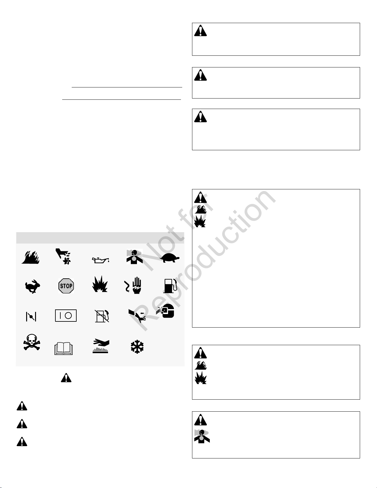
Operator Safety
SAFETY AND CONTROL SYMBOLS
Fire
Fast
Choke
Moving Parts
Stop
On Off
Oil
Explosion
Fuel Shutoff
Toxic Fumes
Shock
Kickback
Slow
Fuel
Wear Eye
Protection
WARNING
Briggs & Stratton does not approve or authorize the use of these engines
on 3-wheel All Terrain Vehicles (ATVs), motor bikes, fun/recreational
go-karts, aircraft products, or vehicles intended for use in competitive
events. Use of these engines in such applications could result in property
damage, serious injury (including paralysis), or even death.
NOTICE: This engine was shipped from Briggs & Stratton without oil. Before you start
the engine, make sure you add oil according to the instructions in this manual. If you
start the engine without oil, it will be damaged beyond repair and will not be covered
under warranty.
WARNING
Fuel and its vapors are extremely flammable and explosive.
Fire or explosion can cause severe burns or death.
When Adding Fuel
Fill fuel tank outdoors or in well-ventilated area.
Check fuel lines, tank, cap, and fittings frequently for cracks or leaks.
Replace if necessary.
When Starting Engine
Ensure that spark plug, muffler, and air cleaner (if equipped) are in place and
secured.
Do not crank engine with spark plug removed.
When Operating Equipment
Never start or run the engine with the air cleaner assembly (if equipped) or the
air filter (if equipped) removed.
When Transporting Equipment
On Natural/Liquid Petroleum (LP) Gas engines, transport with fuel cylinder
empty or valve closed, or fuel tank disconnected.
When Storing Fuel Or Equipment With Fuel In Tank
Store away from furnaces, stoves, water heaters or other appliances that have
pilot lights or other ignition sources because they can ignite fuel vapors.
Hazardous
Chemical
The safety alert symbol is used to identify safety information about hazards that can
result in personal injury. A signal word (DANGER, WARNING, or CAUTION) is used with the
alert symbol to indicate the likelihood and the potential severity of injury. In addition, a hazard
symbol may be used to represent the type of hazard.
Read Manual
Hot Surface
Frostbite
WARNING
Starting engine creates sparking.
Sparking can ignite nearby flammable gases.
Explosion and fire could result.
If there is natural or LP gas leakage in area, do not start engine.
Do not use pressurized starting fluids because vapors are flammable.
DANGER indicates a hazard which, if not avoided, will result in death or
serious injury.
WARNING indicates a hazard which, if not avoided, could result in death or
serious injury.
CAUTION indicates a hazard which, if not avoided, could result in minor or
moderate injury.
WARNING
Engines give off carbon monoxide, an odorless, colorless, poison gas.
Breathing carbon monoxide can cause nausea, fainting or death.
Start and run engine outdoors.
Do not start or run engine in enclosed area, even if doors or windows are open.
NOTICE indicates a situation that could result in damage to the product.
4 VanguardEngines.com
Page 5
WARNING
Not for
Reproduction
Rapid retraction of starter cord (kickback) will pull hand and arm
toward engine faster than you can let go.
Broken bones, fractures, bruises or sprains could result.
When starting engine, pull the starter cord slowly until resistance is felt and then
pull rapidly to avoid kickback.
Remove all external equipment /engine loads before starting engine.
Direct-coupled equipment components such as, but not limited to, blades,
impellers, pulleys, sprockets, etc., must be securely attached.
WARNING
Gaseous fuels are extremely flammable and readily form explosive
air-vapor mixtures at ambient temperatures.
Do not start the engine.
Do not actuate any electrical switches.
Do not use a phone in the vicinity.
Evacuate the area.
Contact the gas supplier or fire department.
WARNING
Rotating parts can contact or entangle hands, feet, hair, clothing, or
accessories.
Traumatic amputation or severe laceration can result.
Operate equipment with guards in place.
Keep hands and feet away from rotating parts.
Tie up long hair and remove jewelry.
Do not wear loose-fitting clothing, dangling drawstrings or items that could
become caught.
WARNING
Running engines produce heat. Engine parts, especially muffler,
become extremely hot.
Severe thermal burns can occur on contact.
Combustible debris, such as leaves, grass, brush, etc. can catch fire.
Allow muffler, engine cylinder and fins to cool before touching.
Remove accumulated debris from muffler area and cylinder area.
It is a violation of California Public Resource Code, Section 4442, to use or
operate the engine on any forest-covered, brush-covered, or grass-covered land
unless the exhaust system is equipped with a spark arrester, as defined in
Section 4442, maintained in effective working order. Other states or federal
jurisdictions may have similar laws. Contact the original equipment
manufacturer, retailer, or dealer to obtain a spark arrester designed for the
exhaust system installed on this engine.
WARNING
Unintentional sparking can result in fire or electric shock.
Unintentional start-up can result in entanglement, traumatic
amputation, or laceration.
Fire hazard
WARNING
Wear eye protection when doing repair work.
Frostbite can result from skin/eye contact with leaking LP liquid.
Installation, adjustment and repair work should be done by a qualified
technician.
Regularly check flexible supply line. Make sure they are in good condition.
Replace damaged or leaking components.
WARNING
Missing or inoperative “fuel lock-off” valve can cause a fire or
explosion.
Do not operate the equipment if the “fuel lock-off” valve is missing or inoperative.
Before performing adjustments or repairs:
Disconnect the spark plug wire and keep it away from the spark plug.
Disconnect battery at negative terminal (only engines with electric start.)
Use only correct tools.
Do not tamper with governor spring, links or other parts to increase engine
speed.
Replacement parts must be of the same design and installed in the same
position as the original parts. Other parts may not perform as well, may damage
the unit, and may result in injury.
Do not strike the flywheel with a hammer or hard object because the flywheel
may later shatter during operation.
When testing for spark:
Use approved spark plug tester.
Do not check for spark with spark plug removed.
en
5
Page 6
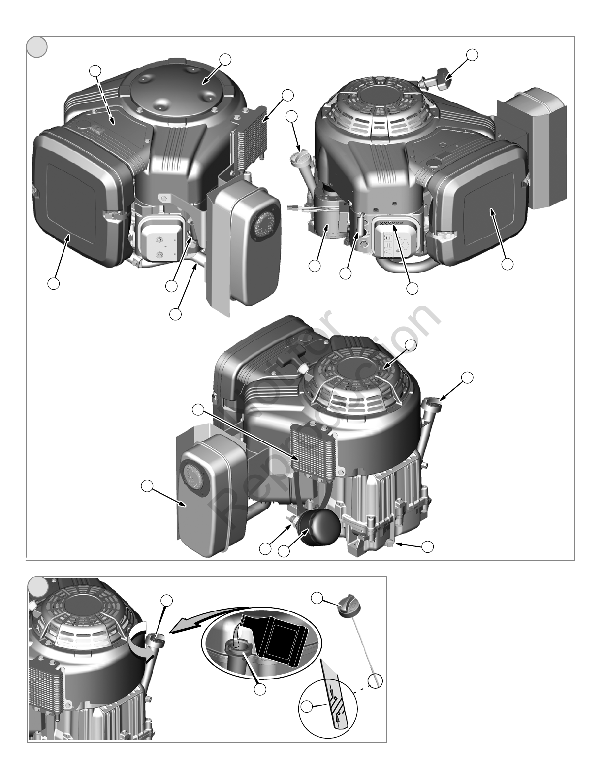
Features and Controls
Not for
Reproduction
Compare the illustration
various features and controls.
A. Engine Identification
Model Type Code
B. Spark Plug
C. Air Cleaner
D. Dipstick
E. Oil Filter (optional)
F. Oil Drain Plug
G. Oil Pressure Sensor
H. Finger Guard
I. Electric Starter
J. Rewind Starter (optional)
K. LPG/NG Mixer
L. Exhaust Manifold
M. Muffler (optional)
N. Oil Cooler (optional)
1
with your engine to familiarize yourself with the location of
Operation
Oil capacity (see the Specifications section)
Fuel Recommendations
WARNING
Missing or inoperative “fuel lock-off” valve can cause a fire or
explosion.
Do not operate the equipment if the “fuel lock-off” valve is missing or inoperative.
Fuel must meet these requirements:
Use clean, dry fuel, free of moisture or any particulate material. Using fuels outside
the following recommended values may cause performance problems.
In engines set up to run on LPG, commercial grade HD5 LPG is recommended.
Recommended fuel composition is fuel with a minimum fuel energy of 2500 BTU’s/ft
with maximum propylene content of 5% and butane and heavier gas content of 2.5%
and minimum propane content of 90%.
NG or LPG engines are certified to operate on natural or liquid propane gas. The
emissions control system for this engine is EM (Engine Modifications).
WARNING: The equipment on which this engine is mounted is equipped
with an automatic safety gas “fuel lock-off” valve. Do not operate the equipment if the
“fuel lock-off” valve is missing or inoperative.
3
Oil Recommendations
We recommend the use of Briggs & Stratton Warranty Certified oils for best
performance. Other high-quality detergent oils are acceptable if classified for service SF,
SG, SH, SJ or higher. Do not use special additives.
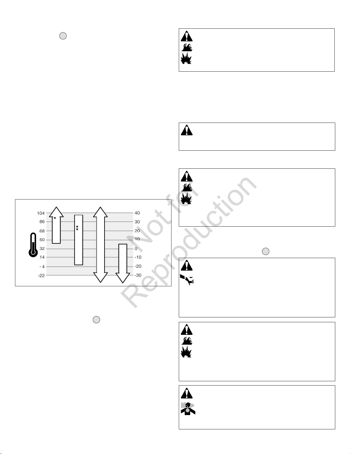
Outdoor temperatures determine the proper oil viscosity for the engine. Use the chart to
select the best viscosity for the outdoor temperature range expected.
°F °C
SAE 30
10W-30
Synthetic 5W-30
* Below 40°F(4°C) the use of SAE 30 will result in hard starting.
** Above 80°F(27°C) the use of 10W-30 may cause increased oil consumption. Check
oil level more frequently.
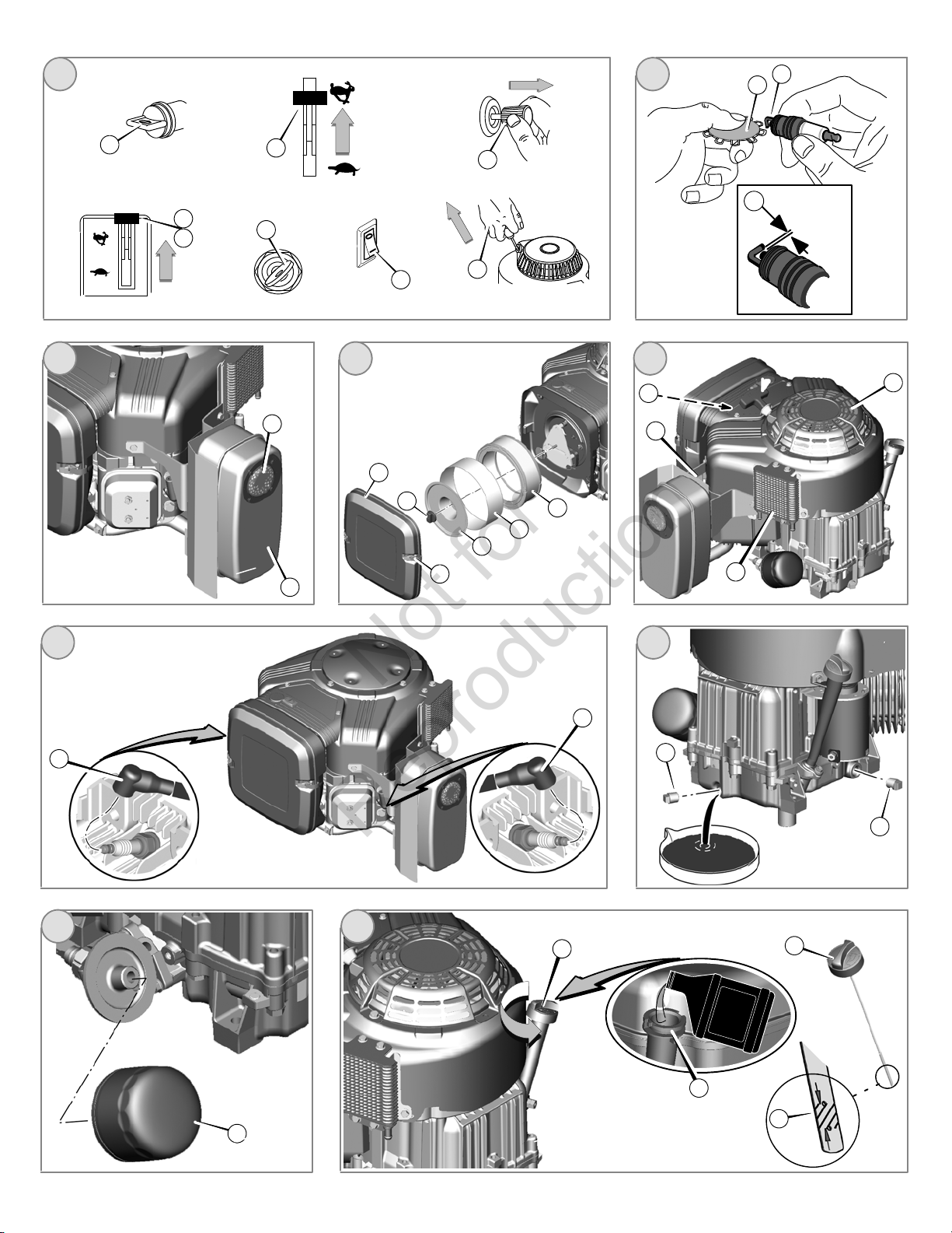
How To Check/Add Oil - Figure
Before adding or checking the oil
Place engine level.
Clean the oil fill area of any debris.
1. Remove the dipstick (A) and wipe with a clean cloth (Figure 2).
2. Fully insert the dipstick.
3. Remove the dipstick and check the oil level. It should be at the top of the full indicator
(B) on the dipstick.
4. If low, add oil slowly into the engine oil fill (C). Do not overfill. After adding oil, wait
one minute and then recheck the oil level.
5. Fully insert the dipstick.
2
5W-30
How To Add Fuel
WARNING
Fuel and its vapors are extremely flammable and explosive.
Fire or explosion can cause severe burns or death.
When Adding Fuel
Fill fuel tank outdoors or in well-ventilated area.
Check fuel lines, tank, cap, and fittings frequently for cracks or leaks.
Replace if necessary.
For information on refueling natural or LP gas engines, read the operating instructions
supplied by the equipment manufacturer.
How To Start The Engine - Figure
3
WARNING
Rapid retraction of starter cord (kickback) will pull hand and arm
toward engine faster than you can let go.
Broken bones, fractures, bruises or sprains could result.
When starting engine, pull the starter cord slowly until resistance is felt and then
pull rapidly to avoid kickback.
Remove all external equipment /engine loads before starting engine.
Direct-coupled equipment components such as, but not limited to, blades,
impellers, pulleys, sprockets, etc., must be securely attached.
WARNING
Fuel and its vapors are extremely flammable and explosive.
Fire or explosion can cause severe burns or death.
When Starting Engine
Ensure that spark plug, muffler, and air cleaner (if equipped) are in place and
secured.
Do not crank engine with spark plug removed.
Oil Pressure
If the oil pressure is too low, a pressure switch (if equipped) will either stop the engine or
activate a warning device on the equipment. If this occurs, stop the engine and check the
oil level with the dipstick.
If the oil level is below the ADD mark, add oil until it reaches the FULL mark. Start the
engine and check for proper pressure before continuing to operate.
If the oil level is between the ADD and FULL marks, do not start the engine. Contact an
Authorized Briggs & Stratton Dealer to have the oil pressure problem corrected.
WARNING
Engines give off carbon monoxide, an odorless, colorless, poison gas.
Breathing carbon monoxide can cause nausea, fainting or death.
Start and run engine outdoors.
Do not start or run engine in enclosed area, even if doors or windows are open.
6 VanguardEngines.com
Page 7
NOTICE: This engine was shipped from Briggs & Stratton without oil. Before you start
Not for
Reproduction
the engine, make sure you add oil according to the instructions in this manual. If you
start the engine without oil, it will be damaged beyond repair and will not be covered
under warranty.
Note: Some engines and equipment have remote controls. See the equipment manual
for location and operation of remote controls.
1. Check the oil level. See the How To Check/Add Oil section.
2. Make sure equipment drive controls, if equipped, are disengaged.
3. Turn the fuel shut-off valve (A), if equipped, to the on position (Figure 3).
4. Push the stop switch (F), if equipped, to the on position.
WARNING: Rapid retraction of the starter cord (kickback) will pull your
hand and arm toward the engine faster than you can let go. Broken bones, fractures,
bruises or sprains could result. When starting engine, pull the starter cord slowly until
resistance is felt and then pull rapidly to avoid kickback.
8. Electric Start: Turn the electric start switch (D) to the on/start position.
Note: If the engine does not start after repeated attempts, go to
VanguardEngines.com or call 1-800-999-9333 (in USA).
NOTICE: To extend the life of the starter, use short starting cycles (five seconds
maximum). Wait one minute between starting cycles.
5. Move the throttle control (B)tothefast
position.
6. Rewind Start: Turn the key switch (D), if equipped, to the run position.
7. Rewind Start: Firmly hold the starter cord handle (E). Pull the starter cord handle
slowly until resistance is felt, then pull rapidly.
Note: If the engine does not start after repeated attempts, go to
VanguardEngines.com or call 1-800-999-9333 (in USA).
position. Operate the engine in the fast
Maintenance
We recommend that you see any Briggs & Stratton Authorized Dealer for all
maintenance and service of the engine and engine parts.
NOTICE: All the components used to build this engine must remain in place for proper
operation.
Emissions Control
Maintenance, replacement, or repair of the emissions control devices and systems
may be performed by any non-road engine repair establishment or individual.
However, to obtain “no charge” emissions control service, the work must be performed
by a factory authorized dealer. See the Emissions Warranty.
WARNING
Unintentional sparking can result in fire or electric shock.
Unintentional start-up can result in entanglement, traumatic
amputation, or laceration.
Fire hazard
Before performing adjustments or repairs:
Disconnect the spark plug wire and keep it away from the spark plug.
Disconnect battery at negative terminal (only engines with electric start.)
Use only correct tools.
Do not tamper with governor spring, links or other parts to increase engine
speed.
Replacement parts must be of the same design and installed in the same
position as the original parts. Other parts may not perform as well, may damage
the unit, and may result in injury.
Do not strike the flywheel with a hammer or hard object because the flywheel
may later shatter during operation.
When testing for spark:
Use approved spark plug tester.
Do not check for spark with spark plug removed.
en
How To Stop The Engine - Figure
1. With the throttle control (B) in the slow position, turn the key switch (D)tothe
off position (Figure 3). Remove the key and keep in a safe place out of the reach of
children.
2. Push the stop switch (F) to the off position.
3. After t he engine stops, turn the fuel shut-off valve (A), if equipped, to the closed
position.
3
Maintenance Chart
First 5 Hours
Change oil
Every8HoursorDaily
Check engine oil level
Clean area around muffler and controls
Every 100 Hours or Annually
Clean or change air filter *
Change engine oil and filter
Replace spark plug
Check muffler and spark arrester
Every 250 Hours or Annually
Check valve clearance. Adjust if necessary.
Every 400 Hours or Annually
Clean air cooling system *
Clean oil cooler fins *
* In dusty conditions or when airborne debris is present, clean more often.
How To Replace The Spark Plug - Figure
Check the gap (A, Figure 4) with a wire gauge (B). If necessary, reset the gap. Install
and tighten the spark plug to the recommended torque. For gap setting or torque, see the
Specifications section.
Note: In some areas, local law requires using a resistor spark plug to suppress ignition
signals. If this engine was originally equipped with a resistor spark plug, use the same
type for replacement.
4
7
Page 8
Inspect Muffler And Spark Arrester - Figure
Not for
Reproduction
5
How To Service The Air Filter - Figure
6
WARNING
Running engines produce heat. Engine parts, especially muffler,
become extremely hot.
Severe thermal burns can occur on contact.
Combustible debris, such as leaves, grass, brush, etc. can catch fire.
Allow muffler, engine cylinder and fins to cool before touching.
Remove accumulated debris from muffler area and cylinder area.
It is a violation of California Public Resource Code, Section 4442, to use or
operate the engine on any forest-covered, brush-covered, or grass-covered land
unless the exhaust system is equipped with a spark arrester, as defined in
Section 4442, maintained in effective working order. Other states or federal
jurisdictions may have similar laws. Contact the original equipment
manufacturer, retailer, or dealer to obtain a spark arrester designed for the
exhaust system installed on this engine.
Remove accumulated debris from muffler area and cylinder area. Inspect the muffler (A,
Figure 5) for cracks, corrosion, or other damage. Remove the spark arrester (B), if
equipped, and inspect for damage or carbon blockage. If damage is found, install
replacement parts before operating.
WARNING: Replacement parts must be of the same design and installed
in the same position as the original parts. Other parts may not perform as well, may
damage the unit, and may result in injury.
How To Change The Oil - Figure
Used oil is a hazardous waste product and must be disposed of properly. Do not discard
with household waste. Check with your local authorities, service center, or dealer for safe
disposal/recycling facilities.
8 9 10 11
Remove Oil
1. With engine off but still warm, disconnect the spark plug wire (A) and keep it away
from the spark plug (Figure 8).
2. Remove the oil drain plug (B, Figure 9). Drain the oil into an approved container.
3. After the oil has drained, install and tighten the oil drain plug.
Change The Oil Filter (if equipped)
Some models are equipped with oil filter. For replacement intervals, see the
Maintenance chart.
1. Drain the oil from the engine. See Remove Oil section.
2. Remove the oil filter (C) and dispose of properly. See Figure 10.
3. Before you install the new oil filter, lightly lubricate the oil filter gasket with fresh,
clean oil.
4. Install t he oil filter by hand until the gasket contacts the oil filter adapter, then tighten
theoilfilter1/2to3/4turns.
5. Add oil. See Add Oil section.
6. Start and run t he engine. As the engine warms up, check for oil leaks.
7. Stop the engine and check the oil level. It should be at the top of the full indicator (F)
on the dipstick.
Add Oil
Place engine level.
Clean the oil fill area of any debris.
See the Specifications section for oil capacity.
1. Remove the dipstick (D) and wipe with a clean cloth (Figure 11).
2. Pour the oil slowly into the engine oil fill (E). Do not overfill. After adding oil, wait
one minute and then check the oil level.
3. Install and tighten the dipstick.
4. Remove the dipstick and check the oil level. It should be at the top of the full indicator
(F) on the dipstick.
5. Install and tighten the dipstick.
WARNING
Fuel and its vapors are extremely flammable and explosive.
Fire or explosion can cause severe burns or death.
Never start or run the engine with the air cleaner assembly (if equipped) or the
air filter (if equipped) removed.
NOTICE: Do not use pressurized air or solvents to clean the filter. Pressurized air can
damage the filter and solvents will dissolve the filter.
See the Maintenance Chart for service requirements.
1. Open the latches (A) and remove the cover (B).SeeFigure6.
2. Remove the nut (D) and the retainer (E)..
3. Remove the air filter (F).
4. Remove the pre-cleaner (G), if equipped, from the air filter.
5. To loosen debris, gently tap the air filter on a hard surface. If the air filter is
excessively dirty, replace with a new air filter.
6. Wash the pre-cleaner in liquid detergent and water. Then allow it to thoroughly air
dry. Do not oil the pre-cleaner.
7. Assemble the dry pre -cleaner to the air filter.
8. Install the air filter and secure with retainer and nut.
9. Install and secure the cover.
How To Clean The Air Cooling System - Figure
7
WARNING
Running engines produce heat. Engine parts, especially muffler,
become extremely hot.
Severe thermal burns can occur on contact.
Combustible debris, such as leaves, grass, brush, etc. can catch fire.
Allow muffler, engine cylinder and fins to cool before touching.
Remove accumulated debris from muffler area and cylinder area.
NOTICE: Do not use water to clean the engine. Water could contaminate the fuel
system. Use a brush or dry cloth to clean the engine.
This is an air cooled engine. Dirt or debris can restrict air flow and cause the engine to
overheat, resulting in poor performance and reduced engine life.
Use a brush or dry cloth to remove debris from the finger guard (A). Keep linkage,
springs and controls (B) clean. Keep the area around and behind the muffler (C)freeof
any combustible debris (Figure 7). Make sure that the oil cooler fins (D) are free of dirt
and debris.
Storage
WARNING
Fuel and its vapors are extremely flammable and explosive.
Fire or explosion can cause severe burns or death.
When Storing Fuel Or Equipment With Fuel In Tank
Store away from furnaces, stoves, water heaters or other appliances that have
pilot lights or other ignition sources because they can ignite fuel vapors.
Engine Oil
While the engine is still warm, change the engine oil.
Troubleshooting
Need Assistance? Go to VanguardEngines.com or call 1-800-999-9333.
8
VanguardEngines.com
Page 9

Specifications
Not for
Reproduction
Engine Specifications
Model 290000
Displacement 29.23 ci (479 cc)
Bore 2.677 in (68 mm)
Stroke 2.598 in (66 mm)
Oil Capacity 46 -- 48 oz (1.36 -- 1.42 L)
Engine Specifications
Model 300000
Displacement 29.23 ci (479 cc)
Bore 2.677 in (68 mm)
Stroke 2.598 in (66 mm)
Oil Capacity 46 -- 48 oz (1.36 -- 1.42 L)
Tune-up Specifications *
Model 290000, 300000
Spark Plug Gap 0.020 in (0.51 mm)
Spark Plug Torque 180 lb-in (20 Nm)
Armature Air Gap 0.008 - 0.012 in (0.20 - 0.30 mm)
Intake Valve Clearance 0.004 - 0.006 in (0.10 - 0.15 mm)
Exhaust Valve Clearance 0.007 - 0.009 in (0.18 - 0.23 mm)
* Engine power will decrease 3.5% for each 1,000 feet (300 meters) above sea level and 1% for each 10 F(5.6 C) above 77 F(25 C). The engine will operate satisfactorily at an
angle up to 15. Refer to the equipment operator’s manual for s afe allowable operating limits on slopes.
Engine Specifications
Model 350000
Displacement 34.78 ci (570 cc)
Bore 2.835 in (72 mm)
Stroke 2.756 in (70 mm)
Oil Capacity 46 -- 48 oz (1.36 -- 1.42 L)
Engine Specifications
Model 380000
Displacement 38.26 ci (627 cc)
Bore 2.972 in (75.5 mm)
Stroke 2.756 in (70 mm)
Oil Capacity 46 -- 48 oz (1.36 -- 1.42 L)
Tune-up Specifications *
Model 350000, 380000
Spark Plug Gap 0.020 in (0.51 mm)
Spark Plug Torque 180 lb-in (20 Nm)
Armature Air Gap 0.008 - 0.012 in (0.20 - 0.30 mm)
Intake Valve Clearance 0.004 - 0.006 in (0.10 - 0.15 mm)
Exhaust Valve Clearance 0.007 - 0.009 in (0.18 - 0.23 mm)
Common Service Parts n
Service Part Part Number
Air Filter -- model 290000, 300000 394018
Air Filter -- model 350000, 380000 841359
Air Filter Pre-cleaner 272490
Oil -- SAE 30 100028
Oil Filter -- 6 cm long 492932
n We recommend that you see any Briggs & Stratton Authorized Dealer for all maintenance and service of the engine and engine parts.
Service Part Part Number
Oil Filter -- 9 cm long 491056
Resistor Spark Plug 491055
Long Life Platinum Spark Plug 5066
Spark Plug Wrench 19374
Spark Tester 19368
en
9
Page 10

BRIGGS & STRATTON ENGINE OWNER WARRANTY POLICY
Not for
Reproduction
July 2010
LIMITED WARRANTY
Briggs & Stratton Corporation will repair or replace, free of charge, any part(s) of the engine that is defective in material or workmanship or both. Transportation charges on
product submitted for repair or replacement under this warranty must be borne by purchaser. This warranty is effective for and is subject to the time periods and conditions
stated below. For warranty service, find the nearest Authorized Service Dealer in our dealer locator map at BRIGGSandSTRATTON.COM, or by calling
1-800-233-3723, or as listed in the ‘Yellow Pages’.
There is no other expressed warranty. Implied warranties, including those of merchantability and fitness for a particular purpose, are limited to one year from
purchase, or to the extent permitted by law. All other implied warranties are excluded. Liability for incidental or consequential damages are excluded to the
extent exclusion is permitted by law. Some states or countries do not allow limitations on how long an implied warranty lasts, and some states or countries do not allow
the exclusion or limitation of incidental or consequential damages, so the above limitation and exclusion may not apply to you. This warranty gives you specific legal rights
and you may also have other rights which vary from state to state and country to country.
STANDARD WARRANTY TERMS *
Brand/Product Type Consumer Use Commercial Use
Vanguardt
Extended Life Seriest; I/C®; Intekt I/C®; Intekt Pro; Commercial Turf Seriest
Professional Seriest with Dura-Boret Cast Iron Sleeve;
850 Seriest with Dura-Bor et Cast Iron Sleeve;
Snow Series MAXt with Dura-Boret Cast Iron Sleeve
All Other Briggs & Stratton Engines Featuring Dura-Boret Cast Iron Sleeve
All Other Briggs & Stratton Engines 2 years 90 days
* These are our standard warranty terms, but occasionally there may be additional warranty coverage that was not determined at time of publication. For a listing of
Y
J
The warranty period begins on the date of purchase by the first retail consumer or commercial end user, and continues for the period of time stated in the table above. “Consumer
use” means personal residential household use by a retail consumer. “Commercial use” means all other uses, including use for commercial, income producing or rental purposes.
Once an engine has experienced commercial use, it shall thereafter be considered as a commercial use engine for purposes of this warranty.
No warranty registration is necessary to obtain warranty on Briggs & Stratton Products. Save your proof of purchase receipt. If you do not provide proof of the initial
purchase date at the time warranty service is requested, the manufacturing date of the product will be used to determine the warranty period.
J
current warranty terms for your engine, go to BRIGGSandSTRATTON.COM or contact your Authorized Briggs & Stratton Service Dealer.
Home Standby Generator applications: 2 years consumer warranty only. No commercial warranty. This warranty does not apply to engines on equipment used for
prime power in place of a utility. Engines used in competitive racing or on commercial or rental tracks are not warranted.
Vanguard installed on standby generators: 2 years consumer use, no warranty commercial use. Vanguard installed on utility vehi cles: 2 years consumer use, 2 years
commercial use. Vanguard 3-cylinder liquid cooled: see Briggs & Stratton 3/LC Engine Owner Warranty Policy.
About Your Warranty
Briggs & Stratton welcomes warranty repair and apologizes to you for being
inconvenienced. Any Authorized Service Dealer may perform warranty repairs. Most
warranty repairs are handled routinely, but sometimes requests for warranty service may
not be appropriate.
If a c ustomer differs with the decision of the Service Dealer, an investigation will be made
to determine whether the warranty applies. Ask the Service Dealer to submit all
supporting facts to his Distributor or the Factory for review. If the Distributor or the
Factory decides that the claim is justified, the customer will be fully reimbursed for those
items that are defective. To avoid misunderstanding which might occur between the
customer and the Dealer, listed below are some of the causes of engine failure that the
warranty does not cover.
Normal wear: Engines, like all mechanical devices, need periodic parts service and
replacement to perform well. Warranty will not cover repair when normal use has
exhausted the life of a part or an engine. Warranty would not apply if engine damage
occurred because of misuse, lack of routine maintenance, shipping, handling,
warehousing or improper installation. Similarly, warranty is void if the serial number of the
engine has been removed or the engine has been altered or modified.
Improper maintenance: The life of an engine depends upon the conditions under which
it operates, and the care it receives. Some applications, such as tillers, pumps and rotary
mowers, are very often used in dusty or dirty conditions, which can cause what appears
to be premature wear. Such wear, when caused by dirt, dust, spark plug cleaning grit, or
other abrasive material that has entered the engine because of improper maintenance, is
not covered by warranty.
This warranty covers engine related defective material and/or workmanship only
and not replacement or refund of the equipment to which the engine may be
mounted. Nor does the warranty extend to repairs required because of:
1 Problems caused by parts that are not original Briggs & Stratton parts.
2 Equipment controls or installations that prevent starting, cause unsatisfactory engine
performance, or shorten engine life. (Contact equipment manufacturer.)
,
3 years 3 years
2 years 1 year
3 Leaking carburetors, clogged fuel pipes, sticking valves, or other damage, caused
by using contaminated or stale fuel.
4 Parts which are scored or broken because an engine was operated with insufficient
or contaminated lubricating oil, or an incorrect grade of lubricating oil (check and
refill when necessary, and change at recommended intervals). OIL GARD may not
shut down running engine. Engine damage may occur if oil level is not properly
maintained.
5 Repair or adjustment of associated parts or assemblies such as clutches,
transmissions, remote controls, etc., which are not manufactured by Briggs &
Stratton.
6 Damage or wear to parts caused by dirt, which entered the engine because of
improper air cleaner maintenance, re-assembly, or use of a non-original air cleaner
element or cartridge. At recommended interv als, clean and/or replace the filter as
stated in the Operator’s Manual.
7 Parts damaged by over-speeding, or overheating caused by grass, debris, or dirt,
which plugs or clogs the cooling fins, or flywheel area, or damage caused by
operating the engine in a confined area without sufficient ventilation. Clean engine
debris at recommended intervals as stated in the Operator’s Manual.
8 Engine or equipment parts broken by excessive vibration caused by a loose engine
mounting, loose cutter blades, unbalanced blades or loose or unbalanced impellers,
improper attachment of equipment to engine crankshaft, over-speeding or other
abuse in operation.
9 A bent or broken crankshaft, caused by striking a solid object with the cutter blade of
a rotary lawn mower, or excessive v-belt tightness.
10 Routine tune-up or adjustment of the engine.
Warranty service is available only through authorized service dealers by Briggs &
Stratton Corporation. Locate your nearest Authorized Service Dealer in our dealer
locator map on BRIGGSandSTRATTON.COM or by calling 1-800-233-3723, or as
listed in the ‘Yellow Pages’.
Y
10 VanguardEngines.com
Page 11

California, U.S. EPA, and Briggs & Stratton Corporation Emissions Control Warranty Statement
Not for
Reproduction
Your Warranty Rights And Obligations
January 2011
The California Air Resources Board, U.S. EPA, and Briggs & Stratton (B&S) are pleased
to explain the emissions control system warranty on your Model Year 2011--2012
engine/equipment. In California, new small off-road engines and large spark ignited
engines less than or equal to 1.0 liter must be designed, built, and equipped to meet the
State’s stringent anti-smog standards. B&S must warrant the emissions control system
on your engine/equipment for the periods of time listed below provided there has been
no abuse, neglect, or improper maintenance of your engine or equipment.
Your emissions control system may include parts such as the carburetor or fuel injection
system, fuel tank, ignition system, and catalytic converter. Also included may be hoses,
belts, connectors, sensors, and other emissions-related assemblies.
Where a warrantable condition exists, B&S will repair your engine/equipment at no cost
to you including diagnosis, parts, and labor.
Manufacturer’s Warranty Coverage:
Small off-road engines and large spark ignited engines less than or equal to 1.0 liter are
warranted for three years. If any emissions-related part on your engine/equipment is
defective, the part will be repaired or replaced by B&S.
Owner’s Warranty Responsibilities:
As the engine/equipment owner, you are responsible for the performance of the
required maintenance listed in your owner’s manual. B&S recommends that you
retain all receipts covering maintenance on your engine/equipment, but B&S cannot
deny warranty solely for the lack of receipts or your failure to ensure the performance
of all scheduled maintenance.
As the engine/equipment owner, you should however be aware that B&S may deny
you warranty coverage if your engine/equipment or a part has failed due to abuse,
neglect, improper maintenance, or unapproved modifications.
You are responsible for presenting your engine/equipment to a B&S distribution
center, servicing dealer, or other equivalent entity, as applicable, as soon as a
problem exists. The warranty repairs should be completed in a reasonable amount of
time, not to exceed 30 days. If you have any questions regarding your warranty
rights and responsibilities, you should contact B&S at (414) 259-5262.
Briggs & Stratton Emissions Control Warranty Provisions
The following are specific provisions relative to your Emissions Control Warranty Coverage. It is in addition to the B&S engine warranty for non-regulated engines found in the
Operator’s Manual.
1. Warranted Emissions Parts
Coverage under this warranty extends only to the parts listed below (the emissions
control systems parts) to the extent these parts were present on the engine
purchased.
a. Fuel Metering System
Cold start enrichment system (soft choke)
Carburetor and internal parts
Fuel pump
Fuel line, fuel line fittings, clamps
Fuel tank, cap and tether
Carbon canister
b. Air Induction System
Air cleaner
Intake manifold
Purge and vent line
c. Ignition System
Spark plug(s)
Magneto ignition system
d. Catalyst System
Catalytic converter
Exhaust manifold
Air injection system or pulse valve
e. Miscellaneous Items Used in Above Systems
Vacuum, temperature, position, time sensitive valves and switches
2. Length of Coverage
Connectors and assemblies
For a period of three years from date of original purchase, B&S warrants to the
original purchaser and each subsequent purchaser that the engine is designed, built,
and equipped so as to conform with all applicable regulations adopted by the Air
Resources Board; that it is free from defects in material and workmanship that could
cause the failure of a warranted part; and that it is identical in all material respects to
the engine described in the manufacturer’s application for certification. The warranty
period begins on the date the engine is originally purchased.
The warranty on emissions-related parts is as follows:
Any warranted part that is not scheduled for replacement as required
maintenance in the owner’s manual supplied, is warranted for the warranty
period stated above. If any such part fails during the period of warranty
coverage, the part will be repaired or replaced by B&S at no charge to the
owner. Any such part repaired or replaced under the warranty will be warranted
for the remaining warranty period.
Any warranted part that is scheduled only for regular inspection in the owner’s
manual supplied, is warranted for the warranty period stated above. Any such
part repaired or replaced under warranty will be warranted for the remaining
warranty period.
Any warranted part that is scheduled for replacement as required maintenance
in the owner’s manual supplied, is warranted for the period of time prior to the
first scheduled replacement point for that part. If the part fails prior to the first
scheduled replacement, the part will be repaired or replaced by B&S at no
charge to the owner. Any such part repaired or replaced under warranty will be
warranted for the remainder of the period prior to the first scheduled
replacement point for the part.
Add on or modified parts that are not exempted by the Air Resources Board
may not be used. The use of any non exempted add on or modified parts by the
owner will be grounds for disallowing a warranty claim. The manufacturer will
not be liable to warrant failures of warranted parts caused by the use of a non
exempted add on or modified part.
3. Consequential Coverage
Coverage shall extend to the failure of any engine components caused by the
failure of any warranted emissions parts.
4. Claims and Coverage Exclusions
Warranty claims shall be filed according to the provisions of the B&S engine
warranty policy. Warranty coverage does not apply to failures of emissions parts
that are not original equipment B&S parts or to parts that fail due to abuse, neglect,
or improper maintenance as set forth in the B&S engine warranty policy. B&S is not
liable for warranty coverage of failures of emissions parts caused by the use of
add-on or modified parts.
Look For Relevant Emissions Durability Period and Air Index Information
On Your Small Off-Road Engine Emissions Label
Engines that are certified to meet the California Air Resources Board (CARB) small
off-road Emissions Standard must display information regarding the Emissions Durability
Period and the Air Index. Briggs & Stratton makes this information available to the
consumer on our emissions labels. The engine emissions label will indicate certification
information.
The Emissions Durability Period describes the number of hours of actual running time
for which the engine is certified to be emissions compliant, assuming proper
maintenance in accordance with the Operating & Maintenance Instructions. The
following categories are used:
Moderate:
Engine is certified to be emissions compliant for 125 hours of actual engine running time.
Intermediate:
Engine is certified to be emissions compliant for 250 hours of actual engine running time.
Extended:
Engine is certified to be emissions compliant for 500 hours of actual engine running time.
For example, a typical walk-behind lawn mower is used 20 to 25 hours per year.
Therefore, the Emissions Durability Period of an engine with an intermediate rating
would equate to 10 to 12 years.
en
Briggs & Stratton engines are certified to meet the United States Environmental
Protection Agency (USEPA) Phase 2 emissions standards. For Phase 2 certified
engines, the Emissions Compliance Period referred to on the Emissions Compliance
label indicates the number of operating hours for which the engine has been shown to
meet Federal emissions requirements.
For engines less than 225 cc displacement.
Category C = 125 hours, Category B = 250 hours, Category A = 500 hours
For engines of 225 cc or more displacement.
Category C = 250 hours, Category B = 500 hours, Category A = 1000 hours
11
Page 12

Información General
Not for
Reproduction
Este manual contiene información de seguridad para que usted tome conciencia de los
peligros y riesgos asociados con los motores, y cómo evitarlos. También contiene
instrucciones para el uso y cuidado apropiados del motor. Ya que Briggs & Stratton
Corporation no conoce necesariamente cuál equipo impulsará este motor, es importante
que usted lea y entienda estas instrucciones y las instrucciones del equipo. Guarde
estas instrucciones para consultarlas en el futuro.
Para conseguir repuestos o asistencia técnica registre los números de modelo, tipo y
código de su motor junto con la fecha de compra. Estos números los encuentra
localizados en su motor (consulte la página de Características y Controles).
Fecha de compra:
MES/DIA/AÑO
Modelo del motor:
Modelo:
Tipo:
Código:
ADVERTENCIA
Ciertos componentes en este producto y sus accesorios relacionados contienen
químicos que el Estado de California considera que ocasionan cáncer, defectos
congénitos y otros daños en el aparato reproductivo. Lávese las manos después de
manejarlos.
ADVERTENCIA
La descarga de escape que expele este motor por este producto contiene químicos
conocidos para el Estado de California que pueden ocasionar cáncer, defectos de
nacimiento u otros daños que pueden ser perjudiciales para la reproducción.
Clasificación de Potencia
La clasificación de potencia total para los modelos individuales de motores a gas se
etiqueta de acuerdo con el código J1940 de SAE (Sociedad de Ingenieros Automotrices)
(Procedimiento de Clasificación de Potencia & Torque del Motor Pequeño) y la
clasificación de desempeño se ha obtenido y se ha corregido de acuerdo con SAE
J1995 (Revisión 2002-05).Los valores de Torque se derivan a 3060 RPM; los valores de
potencia se derivan a 3600 RPM. Los valores netos de potencia se toman con escape y
filtro de aire instalado mientras que los valores de potencia total se recogen sin estos
accesorios. La potencia total real del motor puede ser mayor que la potencia neta del
motor y estar afectada por, entre otras cosas, condiciones ambientales de operación y
variabilidad de motor a motor. Dado el amplio conjunto de productos en los cuales son
puestos los motores, el motor a gas podría no desarrollar la potencia total nominal
cuando sea usado en una parte dada del equipo acoplado. Esta diferencia se debe a
una variedad de factores que incluyen, sin limitarse a, l avierdad de componentes del
motor (filtro de aire, sistema de escape, sistema de carga, sistema de enfriamiento,
carburador, bomba de combustible, etc.), limitaciones de la aplicación, condiciones
ambientales de operación (temperatura, humedad, altitud), y a la variabilidad de motor a
motor. Debido a las limitaciones de fabricación y capacidad Briggs & Stratton puede
sustituir un motor de potencia nominal más alta por esta Serie de motor.
Seguridad del Operario
SÍMBOLOS DE SEGURIDAD Y C ONTROL
Fuego
Fast
Estrangulador
Parar
On Off
Aceite
Explosión
Válvula de Paso
de Combustible
Gases TóxicosPartes en Movimiento
Descarga Eléctrica
Contragolpe
Slow
Combustible
Protección
Para los Ojos
ADVERTENCIA
Briggs & Stratton no aprueba ni autoriza el uso de estos motores en Vehículos Todo
Terreno de 3-ruedas (ATVs), bicicletas motorizadas, karts para diversión/recreo,
productos para aviación o vehículos para uso en eventos competitivos. El uso de
estos motores en tales aplicaciones podría ocasionar daños a la propiedad, lesiones
graves (incluyendo parálisis), o incluso la muerte.
NOTIFICACIÓN: Este motor fue despachado de Briggs & Stratton sin aceite. Antes de
darle arranque al motor, asegúrese de agregar aceite de acuerdo con las instrucciones
de este manual. Si da arranque al motor sin que éste tenga aceite, se dañará hasta tal
punto que no podrá ser reparado y no será cubierto por la garantía.
ADVERTENCIA
El combustible y sus vapores son extremadamente inflamables y
explosivos.
Un incendio o una explosión pueden causar graves quemaduras o la
muerte.
Cuando Aprovisione con Combustible
Llene el tanque de combustible en exteriores o en un área bien ventilada.
Compruebe con frecuencia si existen grietas o fugas en las mangueras de
combustible, el tanque, la tapa y en los accesorios. Cámbielos si es
necesario
Cuando le de Arranque al motor
Asegúrese que la bujía, el mofle y el filtro de aire (si está equipado) estén en su
lugar y firmemente asegurados.
No haga girar el motor si removió la bujía.
Cuando Opere El Equipo
Nunca arranque u opere el motor si removió el conjunto del filtro de aire (si está
equipado) o el filtro de aire (si está equipado).
Cuando Transporte el Equipo
Transporte los motores que operen con Gas Natural/Gas Propano (LP) con el
cilindro de combustible vacío o con la válvula cerrada, o con el tanque
desconectado.
Cuando Almacene el Combustible o el Equipo con Combustible en el Tanque
Almacene a distancia de hornos, estufas, calentadores de agua u otros
aparatos que utilicen testigos piloto u otras fuentes de encendido ya que estos
pueden encender los vapores combustibles.
Químico
Peligroso
El símbolo de aviso de seguridad se utiliza para identificar la información de
seguridad relacionada con los peligros que pueden ocasionar lesiones personales. Se
señaliza con una palabra (PELIGRO, ADVERTENCIA o PRECAUCIÓN) con el símbolo de
aviso para indicar la probabilidad de una lesión y su gravedad potencial. Además, un
símbolo de peligro puede ser utilizado para representar el tipo de peligro.
Lea el
Manual
Superficie
Caliente
Congelado
ADVERTENCIA
Dar arranque al motor crea chispeo.
El chispeo puede encender los gases inflamables cercanos.
Podría ocurrir una explosión o un incendio.
Si hay una fuga de gas natural o gas propano LP en el área, no le de arranque
al motor.
No use líquidos de arranque presurizado ya que los vapores son inflamables.
PELIGRO indica un peligro que si no es evitado, ocasionará la muerte o
heridas graves.
ADVERTENCIA indica un peligro que si no es evitado, podría ocasionar
la muerte o heridas graves.
PRECAUCIÓN indica un peligro que, si no es evitado, podría ocasionar
lesiones menores o moderadas.
NOTIFICACIÓN indica una situación que podría ocasionar daños al
producto.
ADVERTENCIA
Los motores emiten monóxido de carbono, un gas venenoso que
carece de olor y de color.
Respirar monóxido de carbono puede ocasionar náuseas, desmayos
olamuerte.
Dele arranque al motor y opérelo en exteriores.
No le de arranque al motor ni lo opere en un área encerrada, aun cuando las
puertas o las ventanas se encuentren abiertas.
12 VanguardEngines.com
Page 13

ADVERTENCIA
Not for
Reproduction
La retracción rápida de la cuerda de arranque (contragolpe) le halará
la mano y el brazo hacia el motor más rápido de lo que usted la pueda
dejar ir.
Podrían ocasionarse roturas de huesos, fracturas, moretones o
torceduras.
Cuando le de arranque al motor, hale lentamente la cuerda hasta que se sienta
resistencia y después hálela rápidamente para evitar un contragolpe.
Remueva todas las cargas externas del equipo/motor antes de darle arranque
al motor.
Los componentes de acople directo del equipo tal como, pero sin limitarse a,
cuchillas, impulsores, poleas, dientes de piñones, etc. se deben asegurar
firmemente.
ADVERTENCIA
Las partes rotantes pueden tener contacto o enredar las manos, los
pies, el cabello, la ropa o los accesorios.
Puede producirse una traumática amputación o una grave laceración.
Opere el equipo con los protectores en su lugar.
Mantenga sus manos y sus pies a distancia de las partes rotantes.
Recójase el cabello largo y quítese las joyas.
No use ropa floja, tiras que cuelguen ni artículos que puedan ser agarrados.
ADVERTENCIA
Los combustibles gaseosos son extremadamente inflamables y
fácilmente forman mezclas explosivas de aire-vapor en temperaturas
ambiente.
No le de arranque al motor.
No accione ninguno de los suiches eléctricos.
No use el teléfono cerca.
Evacúe el área.
Contacte al proveedor de gas o al departamento de bomberos.
ADVERTENCIA
Protéjase los ojos cuando realice un trabajo de reparación.
Se puede presentar congelamiento por el contacto de la piel/ojos con
una fuga de gas propano.
La instalación, el ajuste y las labores de reparación deben hacerse por un
técnico calificado.
Las mangueras flexibles de suministro deben revisarse con regularidad para
asegurarse que están en buenas condiciones. Reemplace los componentes
que estén dañados o que presenten fugas.
ADVERTENCIA
El funcionamiento de los motores produce calor. Las partes de los
motores, especialmente el mofle, se calientan demasiado.
Pueden ocurrir graves quemaduras a causa de su contacto.
Desechos combustibles, tal como hojas, grama, maleza, etc. pueden
alcanzar a encenderse.
Deje que el mofle, el cilindro y las aletas del motor se enfríen antes de tocarlos.
Remueva los desechos acumulados en el área del mofle y en el área del
cilindro.
Usar u operar el motor en un terreno que contenga bosques, arbustos o pasto
es una violación al Código de Recursos Públicos de California, Sección 4442, a
menos que el sistema de escape esté equipado con un atrapachispas, según se
define en la Sección 4442, mantenido en excelente estado de funcionamiento.
Otros estados o jurisdicciones federales pueden tener leyes similares. Contacte
al fabricante, comerciante o distribuidor del equipo original para obtener un
atrapachispas diseñado para el sistema de escape instalado en este motor.
ADVERTENCIA
Un chispeo involuntario puede producir un incendio o una descarga
eléctrica.
Una puesta en marcha involuntaria puede ocasionar un enredo, una
amputación traumática o una laceración.
Peligro de incendio
Antes de hacer ajustes o reparaciones:
Desconecte el cable de la bujía y mántegalo a distancia de la bujía.
Desconecte la batería en la terminal negativa (únicamente motores con
arranque eléctrico).
Use únicamente las herramientas correctas.
No manipule los resortes del regulador, las varillas u otras partes para
incrementar la velocidad del motor.
Los repuestos deben ser del mismo diseño y ser instalados en la misma
posición que tenían las partes originales. Es posible que otros repuestos no
funcionen tan bien, dañen la unidad y hasta pueden ocasionar lesiones.
No golpee la volante con un martillo ni con un objeto pesado ya que la volante
podría astillarse más adelante durante la operación.
Cuando compruebe chispa:
Utilice un probador aprobado.
No compruebe chispa si removió la bujía.
ADVERTENCIA
Si falta la válvula de “paso de combustible” o si es inoperante se
podría presentar una explosión o un incendio.
No opere el equipo si falta la válvula de “paso de combustible” o si es
inoperante.
es
13
Page 14

Características y Controles
Not for
Reproduction
Compare la ilustración1con su motor para que se familiarice con la ubicación de las
diversas características y controles.
A. Identificación del motor
Modelo, Tipo y Código. Ejemplo:
B. Bujía
C. Filtro de aire
D. Varilla Indicadora Nivel de Aceite
E. Filtro de Aceite (opcional)
F. Tapón Drenaje Aceite
G. Sensor de Presión de Aceite
H. Protector de Dedos
I. Arranque eléctrico
J. Arranque retráctil (opcional)
K. Mezclador LPG/NG
L. Múltiple de Escape
M. Mofle (opcional)
N. Enfriador del aceite (opcional)
Operación
Capacidad de aceite (vea la sección de Especificaciones)
Recomendaciones de Aceite
Se recomienda el uso de aceites Certificados por la Garantía Briggs & Stratton para
mejor rendimiento. Otros aceites detergentes de alta calidad son aceptables si están
clasificados para servicio SF, SG, SH, SJ o superior. No utilice aditivos especiales.
Las temperaturas exteriores determinan la viscosidad del aceite apropiada para el motor.
Utilice el cuadro para seleccionar la mejor viscosidad para el rango de temperatura
exterior esperado.
°F °C
Si el nivel de aceite está entre las marcas ADD y FULL, no de arranque al motor.
Contacte un Distribuidor Autorizado Briggs & Stratton para corregir el problema de
presión de aceite.
Recomendaciones para el Combustible
ADVERTENCIA
Si falta la válvula de “paso de combustible” o si es inoperante se
podría presentar una explosión o un incendio.
No opere el equipo si falta la válvula de “paso de combustible” o si es
inoperante.
El combustible debe cumplir con estos requerimientos:
Utilice combustible limpio, seco, libre de humedad o cualquier partícula. Si se utilizan
combustibles por fuera de los siguientes valores recomendados se podrían
presentar problemas de rendimiento.
En motores ajustados para operar con gas propano LPG, se recomienda un grado
comercial HD5 LPG. La composición recomendada de combustible es combustible
con una energía mínima de combustible de 2500 BTU’s/pies
máximo de propileno del 5% y butano y un contenido más denso de gas del 2.5% y
un contenido mínimo de propano del 90%.
Los motores NG o LPG están certificados para funcionar con gas natural o con gas
propano. El sistema de control de emisiones para este motor es EM (Modificaciones del
Motor).
3
con un contenido
ADVERTENCIA: El equipo en el cual se monta este motor viene
equipado con una válvula automática de seguridad de “cierre de combustible”. No
opere el equipo si falta la válvula de “cierre de combustible” o si es inoperante.
Cómo agregar combustible
ADVERTENCIA
El combustible y sus vapores son extremadamente inflamables y
explosivos.
Un incendio o una explosión pueden causar graves quemaduras o la
SAE 30
10W-30
5W-30 Sintético
5W-30
* El uso de aceite SAE 30 a temperaturas inferiores a 40°F(4°C) producirá dificultad
de arranque.
** El uso de aceite 10W-30 a temperaturas superiores a 80°F(27°C) puede producir
un incremento en el consumo de aceite. Compruebe el nivel de aceite con mayor
frecuencia.
Cómo verificar/Añadir aceite - Figura
Antes de aprovisionar con aceite o de comprobar el nivel de aceite
Coloque el motor a nivel.
Limpie el área de llenado de aceite de todo desecho.
1. Remueva la varilla indicadora de nivel de aceite (A) y límpiela con un trapo limpio
(Figura 2).
2. Inserte completamente la varilla indicadora de nivel de aceite.
3. Remueva la varilla indicadora de nivel de aceite y compruebe el nivel de aceite. El
aceite debe llegar arriba del indicador de (B) en la varilla indicadora de nivel de
aceite.
4. Si el nivel de aceite es bajo, añada aceite lentamente por dentro del tubo de llenado
de aceite (C). No llene excesivamente. Después de aprovisionar con aceite, espere
un minuto y después vuelva a comprobar el nivel de aceite.
5. Inserte completamente la varilla indicadora de nivel de aceite.
2
Presión de Aceite
Si la presión de aceite es muy baja, un suiche de presión (si está equipado) detendrá el
motor o activará un dispositivo de advertencia en el equipo. Si esto ocurre, detenga el
motor y compruebe el nivel de aceite con la varilla indicadora de nivel de aceite.
Si el nivel de aceite está por debajo de la marca ADD, agregue aceite hasta que alcance
la marca FULL. De arranque al motor y compruebe que tenga la presión correcta antes
de continuar la operación.
Para obtener información acerca del aprovisionamiento de motores que funcionan con
gas natural o con gas propano LP, lea las instrucciones de operación suministradas por
el fabricante del equipo.
Cómo Darle Arranque al Motor - Figura
muerte.
Cuando Aprovisione con Combustible
Llene el tanque de combustible en exteriores o en un área bien ventilada.
Compruebe con frecuencia si existen grietas o fugas en las mangueras de
combustible, el tanque, la tapa y en los accesorios. Cámbielos si es
necesario.
3
ADVERTENCIA
La retracción rápida de la cuerda de arranque (contragolpe) le halará
la mano y el brazo hacia el motor más rápido de lo que usted la pueda
dejar ir.
Podrían ocasionarse roturas de huesos, fracturas, moretones o
torceduras.
Cuando le de arranque al motor, hale lentamente la cuerda hasta que se sienta
resistencia y después hálela rápidamente para evitar un contragolpe.
Remueva todas las cargas externas del equipo/motor antes de darle arranque
al motor.
Los componentes de acople directo del equipo tal como, pero sin limitarse a,
cuchillas, impulsores, poleas, dientes de piñones, etc. se deben asegurar
firmemente.
ADVERTENCIA
El combustible y sus vapores son extremadamente inflamables y
explosivos.
Un incendio o una explosión pueden causar graves quemaduras o la
muerte.
Cuando le de Arranque al motor
Asegúrese que la bujía, el mofle, la tapa de combustible y el filtro de aire (si
está equipado) estén en su lugar, y firmemente asegurados.
No haga girar el motor si removió la bujía.
14 VanguardEngines.com
Page 15

ADVERTENCIA
Not for
Reproduction
Los motores emiten monóxido de carbono, un gas venenoso que
carece de olor y de color.
Respirar monóxido de carbono puede ocasionar náuseas, desmayos
olamuerte.
Dele arranque al motor y opérelo en exteriores.
No le de arranque al motor ni lo opere en un área encerrada, aun cuando las
puertas o las ventanas se encuentren abiertas.
NOTIFICACIÓN: Este motor fue despachado de Briggs & Stratton sin aceite. Antes de
darle arranque al motor, asegúrese de aprovisionar con aceite de acuerdo con las
instrucciones de este manual. Si le da arranque al motor sin que esté provisto de aceite,
éste se dañará más allá de la reparación y no será cubierto por la garantía.
Nota: Algunos motores y equipos tienen controles remotos. Vea el manual del equipo
para la ubicación y operación de los controles remotos.
1. Compruebe el nivel de aceite. Vea la sección Cómo Comprobar/Aprovisionar
con Aceite.
2. Asegúrese de que los controles de accionamiento del equipo, si está equipado, se
encuentren desengranados.
3. Gire la válvula de cierre de combustible (A), si está equipado, hacia la posición on
(Figura 3).
4. Mueva el suiche de parada (F), si está equipado, a la posición on.
5. Mueva el control del acelerador (B) hacia la posición fast
el control del acelerador en la posición fast
6. Arranque retráctil: Gire el suiche de llave (D), si está equipado, hacia la posición
run.
.
. Opere el motor con
7. Arranque retráctil: Sostenga firmemente la manija de la cuerda de arranque (E).
Jale lentamente la cuerda de arranque hasta que se sienta resistencia, después
jálela rápidamente.
Nota: Si el motor no arranca después de varios intentos, visite
VanguardEngines.com o llame al 1-800-999-9333 (en los EE.UU.).
ADVERTENCIA: La retracción rápida de la cuerda de arranque
(contragolpe) le halará la mano y el brazo hacia el motor más rápido de lo que
usted la pueda dejar ir. Podrían ocasionarse roturas de huesos, f racturas,
moretones o torceduras. Cuando le de arranque al motor, hale lentamente la
cuerda hasta que se sienta resistencia y después hálela rápidamente para evitar un
contragolpe.
8. Arranque eléctrico: Gire el suiche del arranque eléctrico (D) hacia la posición
on/Start.
Nota: Si el motor no arranca después de varios intentos, visite
VanguardEngines.com o llame al 1-800-999-9333 (en los EE.UU.).
NOTIFICACIÓN: Para prolongar la duración del arrendador, utilice ciclos de
arranque cortos (máximo de cinco segundos). Espere un minuto entre ciclos de
arranque.
Cómo Detener el Motor - Figura
1. Mueva el control del acelerador (B) hacia la posición slow ,gireelsuichede
llave (D) hacia la posición off (Figura 3). Retire la llave y guárdela en un lugar seguro
fuera del alcance de los niños.
2. Mueva el suiche de parada (F), si está equipado, a la posición off.
3. Después de que se detenga el motor, gire la válvula de cierre de combustible (A), si
está equipado, a la posición cerrada.
3
Mantenimiento
Recomendamos contactar un Distribuidor Autorizado Briggs & Stratton para todo lo
relacionado con el mantenimiento y el servicio del motor y sus partes.
NOTIFICACIÓN: Todos los componentes utilizados para fabricar este motor deben
mantenerse en su lugar para una correcta operación.
Control de Emisiones
El mantenimiento, cambio o reparación de los dispositivos y sistemas del control
de emisiones pueden ser realizados por cualquier establecimiento o persona que
repare motores todo terreno. Sin embargo, para obtener servicio de control de
emisiones “sin costo”, la labor debe ser realizada por un distribuidor autorizado por la
fábrica. Vea la Garantía de Emisiones.
ADVERTENCIA
Un chispeo involuntario puede producir un incendio o una descarga
eléctrica.
Una puesta en marcha involuntaria puede ocasionar un enredo, una
amputación traumática o una laceración.
Peligro de incendio
Antes de hacer ajustes o reparaciones:
Desconecte el cable de la bujía y mántegalo a distancia de la bujía.
Desconecte la batería en la terminal negativa (únicamente motores con
arranque eléctrico).
Use únicamente las herramientas correctas.
No manipule los resortes del regulador, las varillas u otras partes para
incrementar la velocidad del motor.
Los repuestos deben ser del mismo diseño y ser instalados en la misma
posición que tenían las partes originales. Es posible que otros repuestos no
funcionen tan bien, dañen la unidad y hasta pueden ocasionar lesiones.
No golpee la volante con un martillo ni con un objeto pesado ya que la volante
podría astillarse más adelante durante la operación.
Cuando compruebe chispa:
Utilice un probador aprobado.
No compruebe chispa si removió la bujía.
es
Cuadro de Mantenimiento
Las Primeras 5 horas
Cambie aceite
Cada 8 Horas o Diariamente
Compruebe el nivel de aceite del motor.
Limpie el área alrededor del mofle y los controles
Cada 100 horas o anualmente
Limpie o cambie el filtro de aire *
Cambie el aceite y el filtro del motor
Cambie la bujía
Compruebe el mofle y el atrapachispas
Cada 250 horas o anualmente
Compruebe la tolerancia de la válvula. Ajuste si es necesario.
Cada 400 horas o anualmente
Limpie el sistema de enfriamiento de aire *
Limpie las aletas del refrigerador de aceite *
* Limpie con mayor frecuencia en condiciones de mucho polvo o cuando el aire
contenga muchas partículas.
Cómo reemplazar la bujía - Figura
Compruebe el entrehierro (A, Figura 4) con un calibrador de alambre (B). Si es
necesario, reajuste el entrehierro. Instale y apriete la bujía al par de apriete
recomendado. Para el ajuste del entrehierro o el par de apriete, consulte la sección de
Especificaciones.
Nota: En algunas áreas, las leyes locales requieren el uso de una bujía con resistencia
para suprimir las señales de encendido. Si este motor vino originalmente equipado con
una bujía con resistencia, utilice el mismo tipo de bujía para el cambio.
4
15
Page 16

Inspección del Mofle y el Atrapachispas - Figura
Not for
Reproduction
5
ADVERTENCIA
El funcionamiento de los motores produce calor. Las partes de los
motores, especialmente el mofle, se calientan demasiado.
Pueden ocurrir graves quemaduras a causa de su contacto.
Desechos combustibles, tal como hojas, grama, maleza, etc. pueden
alcanzar a encenderse.
Deje que el mofle, el cilindro y las aletas del motor se enfríen antes de tocarlos.
Remueva los desechos acumulados en el área del mofle y en el área del
cilindro.
Constituye una violación del Código de Recursos Públicos de California,
Sección 4442, el utilizar u operar el motor en terrenos cubiertos con bosques,
maleza o grama, a menos que el sistema de escape esté equipado con un
atrapachispas, tal como se define en la Sección 4442, mantenido en correcto
orden de funcionamiento. Otros estados pueden tener leyes similares. Póngase
en contacto con el fabricante, minorista o distribuidor del equipo original para
obtener un atrapachispas diseñado para el sistema de escape instalado en este
motor.
Remueva los desechos acumulados en el área del mofle y en el área del cilindro.
Inspeccione el mofle (A, Figura 5) en busca de grietas, corrosión u otros daños.
Remueva el atrapachispas (B), en caso de estar equipado, e inspeccione en búsqueda
de daños u obstrucciones de carbón. Si se encuentran daños, instale los repuestos
antes de operar.
ADVERTENCIA: Los repuestos deben ser del mismo diseño y ser
instalados en la misma posición que tenían las partes originales. Es posible que
otros repuestos no funcionen tan bien, dañen la unidad y hasta pueden ocasionar
lesiones.
4. Remueva la varilla indicadora de nivel de aceite y compruebe el nivel de aceite. El
aceite debe llegar arriba del indicador de (F) en la varilla indicadora de nivel de
aceite.
5. Coloque y ajuste la varilla indicadora.
Cómo mantener el filtro de aire - Figura
6
ADVERTENCIA
El combustible y sus vapores son extremadamente inflamables y
explosivos.
Un incendio o una explosión pueden causar graves quemaduras o la
muerte.
Nunca arranque u opere el motor si removió el conjunto del filtro de aire (si está
equipado) o el filtro de aire (si está equipado).
NOTIFICACIÓN: No use aire a presión ni solventes para limpiar el filtro. El aire a
presión puede dañar el filtro y los solventes pueden disolverlo.
Consulte el Cuadro de Mantenimiento para los requerimientos de servicio.
1. Abra los seguros (A) y remueva la tapa (B).VealaFigura6.
2. Remueva la tuerca (D) y el retenedor (E).
3. Remueva el filtro de aire (F).
4. Remueva el pre-filtro (G), si está equipado, del filtro de aire.
5. Para aflojar los desechos, golpee suavemente el filtro sobre una superficie dura. Si
el filtro está excesivamente sucio, reemplácelo por un filtro nuevo.
6. Lave el pre-filtro en detergente líquido y agua. Luego permita que se seque
completamente al aire. No aceite el pre-filtro.
7. Instale el pre-filtro seco sobre el filtro de aire.
8. Instale el filtro de aire y asegúrelo con el retenedor y la tuerca.
9. Instale y asegure la cubierta.
Cómo cambiar el aceite - Figura
El aceite usado es un producto de desecho peligroso y se debe disponer de éste
adecuadamente. No lo descarte en la basurera de la casa. Verifique con sus autoridades
locales, con el centro de servicio, o con su distribuidor para obtener información acerca
de las facilidades seguras para su destrucción/reciclaje.
8 9 10
Remoción del Aceite
1. Con el motor apagado pero aún caliente, desconecte el cable de la bujía (A)y
manténgalo a distancia de la bujía (Figura 8).
2. Remueva el tapón de drenaje de aceite (B, Figura 9). Drene el aceite a un recipiente
aprobado.
3. Después de haber drenado el aceite del motor, instale y apriete el tapón de drenaje
de aceite.
Cambie el Filtro de Aceite (si está equipado)
Algunos modelos están equipados con un filtro de aceite. Para saber cada cuánto
requiere ser reemplazado, consulte el cuadro de Mantenimiento.
1. Drene el aceite del motor. Consulte la sección Remoción del Aceite.
2. Remueva el filtro de aceite (C) y deséchelo de manera adecuada. Vea la Figura 10.
3. Antes de instalar el nuevo filtro de aceite, lubrique un poco el empaque del filtro de
aceite con aceite fresco y limpio.
4. Instale manualmente el filtro de aceite de hasta que el empaque haga contacto con
el adaptador del filtro de aceite, luego apriete el filtro de aceite dándole 1/ 2 a 3/4 de
giro.
5. Añada aceite. Consulte la sección Aprovisionamiento de Aceite.
6. De arranque y opere el motor. A medida que el motor se caliente compruebe si hay
fugas de aceite.
7. Detenga el motor y compruebe el nivel de aceite. El aceite debe llegar arriba del
indicador de (F) en la varilla indicadora de nivel de aceite.
Aprovisionamiento de Aceite
Coloque el motor a nivel.
Limpie el área de llenado de aceite de todo desecho.
Consulte la sección de Especificaciones para la capacidad de aceite.
1. Remueva la varilla indicadora de nivel de aceite (D) y límpiela con un trapo limpio
(Figura 11).
2. Vierta el aceite lentamente por dentro del tubo de llenado de aceite (E). No lo llene
excesivamente. Después de aprovisionar con aceite, espere un minuto y vuelva a
comprobar el nivel de aceite.
3. Coloque y ajuste la varilla indicadora.
16
Cómo Limpiar el Sistema de Enfriamiento de Aire - Figura
7
ADVERTENCIA
El funcionamiento de los motores produce calor. Las partes de los
motores, especialmente el mofle, se calientan demasiado.
Pueden ocurrir graves quemaduras a causa de su contacto.
Desechos combustibles, tal como hojas, grama, maleza, etc. pueden
alcanzar a encenderse.
Deje que el mofle, el cilindro y las aletas del motor se enfríen antes de tocarlos.
Remueva los desechos acumulados en el área del mofle y en el área del
cilindro.
NOTIFICACIÓN: No use agua para limpiar el motor. El agua podría contaminar el
sistema de combustible. Utilice un cepillo o un trapo seco para limpiar el motor.
Este es un motor enfriado por aire. Las suciedades o los desechos pueden restringir el
flujo de aire y ocasionar recalentamiento en el motor, produciendo un desempeño pobre
y una vida del motor reducida.
Utilice un cepillo o un trapo seco para remover los desechos del protector de dedos (A).
Mantenga las varillas, los resortes y los controles (B) limpios. Mantenga el área
alrededor y por detrás del mofle (C) libre de todo desecho combustible (Figura 7).
Asegúrese que las aletas del refrigerador de aceite (D) estén libres de mugre y de
desechos.
Bodegaje
ADVERTENCIA
El combustible y sus vapores son extremadamente inflamables y
explosivos.
Un incendio o una explosión pueden causar graves quemaduras o la
muerte.
Cuando Almacene el Combustible o el Equipo con Combustible en el Tanque
Almacene a distancia de hornos, estufas, calentadores de agua u otros
aparatos que utilicen testigos piloto u otras fuentes de encendido ya que estos
pueden encender los vapores combustibles.
Aceite del Motor
Cambie el aceite del motor mientras que el motor se encuentre todavía caliente.
Detección de Fallas
¿Necesita Asistencia? Vaya a VanguardEngines.com o marque el teléfono
1-800-999-9333.
VanguardEngines.com
Page 17

Especificaciones
Not for
Reproduction
Especificaciones del Motor
Modelo 290000
Desplazamiento 29,23 in3(479 cm3)
Diámetro Interno del Cilindro 2,677 in (68 mm)
Carrera 2,598 in (66 mm)
Capacidad de Aceite 46 -- 48 oz (1,36 -- 1,42 L)
Especificaciones del Motor
Modelo 300000
Desplazamiento 29,23 in3(479 cm3)
Diámetro Interno del Cilindro 2,677 in (68 mm)
Carrera 2,598 in (66 mm)
Capacidad de Aceite 46 -- 48 oz (1,36 -- 1,42 L)
Especificaciones de Ajuste *
Modelo 290000, 300000
Entrehierro de la Bujía 0,020 in (0,51 mm)
Torque de la Bujía 180 lb-in (20 Nm)
Entrehierro Inducido 0,008 - 0,012 in (0,20 - 0,30 mm)
Tolerancia de la Válvula de Admisión 0,004 - 0,006 in (0,10 - 0,15 mm)
Tolerancia de la Válvula de Escape 0,007 - 0,009 in (0,18 - 0,23 mm)
* La potencia del motor disminuirá 3.5% por cada 1,000 pies (300 metros) sobre el nivel del mar y un 1% por cada 10 F(5.6 C) por encima de 77 F(25 C). El motor operará
satisfactoriamente a un ángulo de hasta 15. Refiérase al manual del operador del equipo para obtener información acerca de los límites de operación permitidos en pendientes.
Especificaciones del Motor
Modelo 350000
Desplazamiento 34,78 in3(570 cm3)
Diámetro Interno del Cilindro 2,835 in (72 mm)
Carrera 2,756 in (70 mm)
Capacidad de Aceite 46 -- 48 oz (1,36 -- 1,42 L)
Especificaciones del Motor
Modelo 380000
Desplazamiento 38,26 in3(627 cm3)
Diámetro Interno del Cilindro 2,972 in (75,5 mm)
Carrera 2,756 in (70 mm)
Capacidad de Aceite 46 -- 48 oz (1,36 -- 1,42 L)
Especificaciones de Ajuste *
Modelo 350000, 380000
Entrehierro de la Bujía 0,020 in (0,51 mm)
Torque de la Bujía 180 lb-in (20 Nm)
Entrehierro Inducido 0,008 - 0,012 in (0,20 - 0,30 mm)
Tolerancia de la Válvula de Admisión 0,004 - 0,006 in (0,10 - 0,15 mm)
Tolerancia de la Válvula de Escape 0,007 - 0,009 in (0,18 - 0,23 mm)
Partes de Servicio Comunes n
Parte de Servicio Numero de parte
Filtro de aire -- modelo 290000, 300000 394018
Filtro de aire -- modelo 350000, 380000 841359
Pre-filtro filtro de aire 272490
Aceite -- SAE 30 100028
Filtro de Aceite - 6 cms de largo 492932
n Recomendamos que contacte a cualquier Distribuidor de Servicio Autorizado Briggs & Stratton para todo lo relacionado con el mantenimiento y el servicio del motor y sus partes.
Parte de Servicio Numero de parte
Filtro de Aceite - 9 cms de largo 491056
Bujía con Resistencia 491055
Bujía de Platino de Larga Vida 5066
Llave de Bujía 19374
Probador de Chispa 19368
es
17
Page 18

PÓLIZA DE GARANTÍA DEL PROPIETARIO DEL MOTOR BRIGGS & STRATTON
Not for
Reproduction
Julio 2010
GARANTIA LIMITADA
Briggs & Stratton Corporation reparará o reemplazará, sin costo alguno, cual(es)quier parte(s) del motor considerada(s) como defectuosas en material, mano de obra o
ambos. Los gastos de transporte del producto sometido a reparación o cambio bajo esta Garantía deben ser abonados por el comprador. Esta garantía tiene vigencia y está
sujeta a los períodos y condiciones establecidos a continuación. Para recibir servicio de garantía, contacte el Distribuidor de Servicio Autorizado más cercano en nuestro
mapa de localización de distribuidores en BRIGGSandSTRATTON.COM, o marque el 1-800-233-3723, o según aparezca listado en las ‘Páginas Amarillas’.
No existe ninguna otra garantía expresa. Las garantías implícitas, incluso aquellas de mercantibilidad y adaptabilidad para un fin determinado quedan limitadas a
un año a partir de la fecha de compra o a la extensión permitida por la ley. Quedan excluidas todas las garantías implícitas. La responsabilidad por daños
fortuitos o consecuentes bajo cualesquier y todas las garantías queda excluida en la medida que dicha exclusión sea permitida por la ley. Algunos estados o países
no contemplan limitaciones en cuanto a la duración de una garantía implícita, y otros países o estados no permiten la exclusión o limitación de daños consecuentes o
incidentales, en cuyo caso la limitación y la exclusión anteriores pueden no ser aplicables para usted. Esta garantía le otorga derechos legales específicos, pudiendo tener a
su vez otros derechos que varían de un país a otro y de un estado a otro.
TÉRMINOS ESTÁNDAR PARA GARANTÍA *
Marca/Tipo de Producto Uso Privado Uso Comercial
Vanguardt
Extended Life Seriest; I/C®; Intekt I/C®; Intekt Pro; Commercial Turf Seriest
Professional Seriest con Funda de Hierro Colado Dura-Boret;
850 Seriest con Funda de Hierro Colado Dura-Boret;
Snow Series MAXt con Funda de Hierro Colado Dura-Boret
Todos los otros motores Briggs & Stratton que incorporan Funda de Hierro Colado Dura-Boret
Todos los otros motores Briggs & Stratton 2 años 90 días
* Éstos son nuestros términos de garantía estándares, pero de vez en cuando puede existir una cobertura adicional de la garantía que no fue determinada enel
Y
J
El período de garantía comienza a partir de la fecha en la cual lo compró el consumidor detallista original o usuario final comercial, y continúa por el período de tiempo establecido en
la tabla anterior. “Uso privado” significa uso doméstico personal por el consumidor detallista original. “Uso Comercial” significa todos los otros usos, incluyendo fines comerciales o
que produzcan ingresos o renta. Una vez que el motor haya experimentado uso comercial, será considerado en adelante como motor de uso comercial para fines de esta garantía.
No es necesario registrar la garantía para obtener servicio de Briggs & Stratton Products. Guarde su recibo de compra. Si no aporta la prueba de la fecha de compra
inicial en el momento de requerir servicio de garantía, se utilizará la fecha de fabricación del producto para determinar el período de garantía.
J
momento de la publicación. Para obtener un listado de los términos de garantía corrientes para su motor, vaya a BRIGGSandSTRATTON.COM o póngase en
contacto con su Distribuidor de Servicio autorizado de Briggs & Stratton.
Aplicaciones para Generadores Domésticos: Garantía de sólo 2 años para el consumidor. Los motores usados en aplicaciones de Generadores Domésticos están
garantizados únicamente para uso privado. Esta garantía no se aplica a motores en equipos usados para energía principal en lugar de un servicio. Los motores
usados en eventos competitivos o en trayectorias comerciales o de renta no están cubiertos por la garantía.
Vanguard instalado en generadores standby: 2 años de uso por el consumidor, la garantía solo aplica para generadores en uso privado. Vanguard instalado en
vehículos de servicio: 2 años de uso por el consumidor, 2 años para uso comercial. Vanguard para líquido enfriado de 3-cilindros: ver la Garantía en la Póliza de
Propiedad 3/LC de Briggs & Stratton.
Acerca de su Garantía
Briggs & Stratton recibe con agrado la reparación bajo garantía y le pedimos disculpas
por los inconvenientes presentados. Cualquier Distribuidor de Servicio Autorizado puede
hacer reparaciones bajo garantía. La mayor parte de las reparaciones bajo garantía se
atienden de manera rutinaria, pero algunas veces las peticiones para el servicio de
garantía pueden no ser apropiadas.
Si un cliente no está de acuerdo con la decisión del Distribuidor de Servicio, se realizará
una investigación para determinar la aplicabilidad de la garantía. Pida a su Distribuidor
de Servicio que envíe toda la información pertinente a su Distribuidor o a la Fábrica para
proceder a su revisión. Si el Distribuidor o la Fábrica deciden que su reclamación es
justificada, al cliente le será reembolsado totalmente el importe de aquellas partes que
son defectuosas. Para evitar cualquier malentendido que pudiera presentarse entre el
cliente y el Distribuidor de Servicio, listamos a continuación algunas de las causas de
fallas del motor que no cubre la garantía.
Desgaste Normal: Los motores necesitan, como todos los dispositivos mecánicos, el
cambio y el servicio periódico de las partes para desempeñarse bien. La garantía no
cubrirá la reparación cuando el uso normal haya agotado la vida de una parte o del
motor. La garantía no podría aplicarse si el daño del motor ocurrió debido a abuso, falta
del mantenimiento habitual, transporte, manejo, bodegaje o instalación inapropiados. De
igual manera se invalidará la garantía si el número serial del motor ha sido removido o si
el motor ha sido alterado o modificado.
Mantenimiento Incorrecto: La vida útil de un motor depende de las condiciones bajo
las cuales opere el motor y del cuidado que éste reciba. Algunas aplicaciones, tales
como cultivadoras, bombas y máquinas cortacésped rotantes, se utilizan con mucha
frecuencia en condiciones de mucho polvo o en condiciones muy sucias, las cuales
pueden hacer que parezca un desgaste prematuro del motor. Tal desgaste, cuando es
ocasionado por suciedad, polvo o por el hecho de limpiar la bujía con chorro de arena, o
porque otro material abrasivo haya entrado al motor debido a un mantenimiento no
apropiado, no será cubierto por la garantía.
Esta garantía cubre únicamente
relacionados con el motor, y no el cambio o reembolso del equipo en el cual
haya sido montado el motor. Ni extender á la garantí a a reparaciones requeridas
debido a:
1 Problemas ocasionados por el uso de partes que no sean partes originales
Briggs & Stratton.
2 Controles del equipo o instalaciones que impidan el arranque, ocasionando un
rendimiento poco satisfactorio del motor, o que acorten la vida del motor. (Contacte
el fabricante del equipo.)
, material defectuoso y/o mano de obra
3 años 3 años
2 años 1 año
3 Carburadores con fugas, conductos de combustible obstruidos, válvulas atascadas
u otros daños causados por el uso de combustible contaminado o pasado.
4 Partes que se hayan rayado o reventado por operar el motor con aceite lubricante
insuficiente o contaminado, o por el uso del grado de viscosidad de aceite
incorrecto (compruebe el nivel de aceite y termine de aprovisionar cuando sea
necesario, y cambie aceite según los intervalos recomendados.) El dispositivo
protector del aceite OIL GARD no se puede apagar durante la operación del motor.
Se podrían presentar daños en el motor si el nivel de aceite no se mantiene
correctamente.
5 Reparación o ajuste de partes asociadas o conjuntos tales como embragues,
transmisiones, controles remoto, etc., los cuales no son fabricados por Briggs &
Stratton.
6 Daño o desgaste de partes causado por la entrada de suciedades al motor debido
al mantenimiento incorrecto del filtro de aire, montaje incorrecto, o por el uso de un
elemento o cartucho para el filtro de aire que no sea original. Limpie y/o cambie el
filtro según los intervalos recomendados de acuerdo a lo establecido en el Manual
del Operador.
7 Partes dañadas por velocidad excesiva o recalentamiento causado por residuos de
grama, desechos o suciedades los cuales taponan u obstruyen las aletas de
enfriamiento, o el área de la volante, o por daños causados por operar el motor en
un área confinada sin la suficiente ventilación. Limpie los desechos del motor según
os intervalos recomendados de acuerdo a lo establecido en el Manual del
Operador.
8 Partes del motor o del equipo quebradas por vibración excesiva causada por un
montaje flojo del motor, cuchillas de corte flojas, cuchillas o impulsores flojos o no
balanceados, fijación incorrecta del equipo al cigüeñal del motor, velocidad excesiva
u otro abuso en la operación.
9 Un cigüeñal deformado o quebrado causado por golpear con un objeto sólido la
cuchilla de corte de una máquina cortacésped rotante, o por tensión excesiva de las
correas en v.
10 Afinación o ajuste de rutina del motor.
Se dispone del servicio de garantía únicamente a través de distribuidores de
servicio autorizados por Briggs & Stratton Corporation. Localice su Distribuidor de
Servicio Autorizado más cercano en nuestro mapa de localización de distribuidores
en BRIGGSandSTRATTON.COM, o marcando el teléfono 1-800-233-3723, o según
aparezca listado en las ’Páginas Amarillas’.
Y
18 VanguardEngines.com
Page 19

Informations générales
Not for
Reproduction
Ce manuel contient des informations concernant la sécurité visant à attirer l’attention des
usagers sur les dangers et les risques associés aux moteurs. Il contient aussi des
instructions d’utilisation et d’entretien appropriées à ce moteur. Briggs & Stratton
Corporation ne sachant pas forcément sur quel équipement ce moteur est monté, il est
important de lire et de comprendre ces instructions ainsi que celles c oncernant
l’équipement utilisé. Conserver ces instructions originales pour un usage ultérieur.
Pour obtenir des pièces de rechange ou une assistance technique, reporter ici les
numéros de Modèle, Type et Code du moteur ainsi que la date d’achat. Ces numéros
sont situés sur le moteur (voir la page Caractéristiqueset commandes).
Date d’achat:
JJ/MM/AAAA
Modèle de moteur:
Modèle:
Code:Type:
AVERTISSEMENT
Certains composés de ce produit et de ses accessoires contiennent des produits
chimiques connus dans l’État de Californie pour provoquer des cancers et des
troubles de la procréation. Se laver les mains après chaque manipulation.
AVERTISSEMENT
Les gaz d’échappement de ce moteur contiennent des substances chimiques
pouvant causer des cancers, des malformations fœtales ou d’autres problèmes de
fécondation.
Puissance théorique
La puissance théorique brute pour chaque modèle de moteur à essence est indiquée
conformément à la norme J1940 (procédure de calcul de la puissance et du couple des
petits moteurs) de la SAE (Society of Automotive Engineers) et les performances
théoriques ont été obtenues et corrigées selon SAE J1995 (révision 2002-05). Les
valeurs de couple sont définies à 3060 tr/min et les valeurs de puissance sont définies à
3600 tr/min. Les valeurs nettes de puissance sont établies avec l’échappement et le filtre
à air installés tandis que les valeurs brutes de puissance sont définies sans ces
accessoires. La puissance brute réelle du moteur sera supérieure à la puissance nette et
est influencée notamment par les conditions ambiantes de fonctionnement et les
variations d’un moteur à l’autre. Compte tenu de la grande variété de machines sur
lesquelles nos moteurs sont utilisés, il se peut que le moteur à essence ne développe
pas sa puissance brute théorique une fois qu’il est monté sur une machine particulière.
Cette différence s’explique par un grand nombre de facteurs, tels que (liste non
limitative), les accessoires (filtre à air, échappement, admission, refroidissement,
carburateur, pompe à essence, etc.), les limites d’utilisation, les conditions ambiantes
d’utilisation (température, humidité, altitude) et les variations d’un moteur à l’autre. Pour
des raisons de fabrication et de capacité limitées, Briggs & Stratton est susceptible de
remplacer un moteur par une version plus puissante pour ces moteurs de série.
Sécuritéde l’utilisateur
SYMBOLES DE SÉCURITÉ ET DE COMMANDE
Incendie
Fast
Starter
Pièces en
mouvement
Arrêter
Marche Arrêt
Huile
Explosion
Robinet
d’essence
Fumées
toxiques
Choc
Retour brutal
Slow
Essence
Porter des
lunettes
AVERTISSEMENT
Briggs & Stratton n’approuve pas et n’autorise pas l’utilisation de ces moteurs sur
les véhicules tout-terrain à 3 roues, les motocyclettes, les karts de loisir, les
aéroplanes ou les véhicules destinés à être utilisés en compétition. L’utilisation de
ces moteurs pour ces applications peut entraîner des dommages matériels, des
lésions graves (y compris la paralysie) ou la mort.
AVI S : Ce moteur a été expédié par Briggs & Stratton sans huile. Avant de le démarrer,
s’assurer d’avoir fait le plein d’huile selon les instructions de ce manuel. Si le moteur est
démarré sans huile, il sera endommagé irrémédiablement et ne sera pas couvert par la
garantie.
AVERTISSEMENT
Le combustible et ses vapeurs sont extrêmement inflammables et
explosifs.
Un incendie ou une explosion peut entraîner des blessures très
graves ou même la mort.
Pour faire le plein
Remplir le réservoir de carburant à l’extérieur ou dans un local extrêmement
bien ventilé.
Contrôler que les durites, le réservoir, le bouchon et les raccords de
carburant ne présentent ni fissures ni fuites. Remplacer si nécessaire.
Pour démarrer le moteur
S’assurer que la bougie, le bouchon du réservoir de carburant et le filtre à air
sont le cas échéant montés et solidement fixés.
Ne pas faire tourner le moteur avec la bougie enlevée.
Lors de l’utilisation de l’équipement
Ne pas démarrer ou faire fonctionner un moteur sans filtre à air ou avec le filtre
à air enlevé (le cas échéant).
Pour transporter l’équipement
Pour les moteurs à gaz naturel/GPL, transporter avec le cylindre de carburant
vide, le robinet fermé ou le réservoir débranché.
Pour stocker du carburant ou l’équipement avec un réservoir plein
Les ranger loin des chaudières, cuisinières, chauffe-eau ou tout autre appareil
comportant une veilleuse ou une source susceptible de produire une étincelle,
car ils pourraient enflammer les vapeurs de carburant.
Produits chimiques
dangereux
Le symbole d’alerte de sécurité est utilisé pour identifier des informations sur des
risques qui peuvent entraîner des blessures. Un mot (DANGER, AVER TISSEMENT,
ATTENTION) est utilisé avec le symbole d’alerte pour indiquer le risque de blessure. En
outre, un signal de danger peut être utilisé pour représenter le type de risque.
Lire le manuel
Surface
très chaude
Engelures
DANGER indique un risque qui, s’il n’est pas éliminé, entraînera la mort ou
des blessures très graves.
AVERTISSEMENT indique un risque qui, s’il n’est pas éliminé, pourrait
entraîner la mort ou des blessures très graves.
ATTENTION indique un risque qui, s’il n’est pas éliminé, pourrait entraîner
des blessures mineures ou légères.
AVIS indique une situation qui pourrait endommager l’appareil.
AVERTISSEMENT
Le démarrage du moteur produit des étincelles.
Les étincelles peuvent enflammer les gaz inflammables à proximité.
Ceci pourrait provoquer une explosion ou un incendie.
S’il y a une fuite de gaz naturel ou de GPL à proximité, ne pas démarrer le
moteur.
Ne pas utiliser de liquides de démarrage sous pression car leurs vapeurs sont
inflammables.
AVERTISSEMENT
Les moteurs produisent du monoxyde de carbone, qui est un gaz
toxique inodore et invisible.
L’inhalation de monoxyde de carbone peut provoquer des nausées,
un évanouissement et entraîner la mort.
Démarrer et faire fonctionner le moteur à l’extérieur.
Ne pas démarrer ou faire fonctionner le moteur dans un local fermé, même si
les portes et les fenêtres sont ouvertes.
fr
19
Page 20

AVERTISSEMENT
Not for
Reproduction
La rétraction rapide de la corde de lanceur (retour brutal) tirera votre
main et votre bras vers le moteur beaucoup plus vite que vous ne
pourrez les laisser partir.
Ceci pourrait entraîner des fêlures, des fractures, des ecchymoses ou
des foulures.
Pour démarrer le moteur, tirer lentement sur la corde jusqu’à sentir une
résistance et tirer alors rapidement af in d’éviter l’effet de rétraction.
Retirer tout équipement extérieur/charge avant de démarrer le moteur.
Les composants directement couplés à l’équipement, tels que lames, turbines,
poulies, engrenages, etc. sans que cette liste soit limitative, devront être
fermement arrimés.
AVERTISSEMENT
Les combustibles gazeux sont extrêmement inflammables et forment
facilement un mélange air-vapeur explosif à la température ambiante.
Ne pas démarrer le moteur.
Ne pas manipuler d’interrupteur électrique.
Ne pas utiliser de téléphone à proximité.
Évacuer la zone.
Prendre contact avec la compagnie du gaz ou avec les pompiers.
AVERTISSEMENT
Les pièces en rotation peuvent toucher ou saisir les mains, les pieds,
les cheveux, les vêtements ou les accessoires.
Le résultat peut en être une amputation ou une lacération grave.
Ne faire fonctionner l’équipement qu’avec les protections en place.
Ne pas approcher les mains ou les pieds des pièces en mouvement.
Attacher les cheveux longs et retirer les bijoux.
Ne pas porter de vêtements amples, de ceintures larges pendantes ou tout
vêtement pouvant être saisi.
AVERTISSEMENT
Un moteur en marche produit de la chaleur. Les pièces du moteur, et
plus particulièrement le silencieux, deviennent extrêmement chaudes.
Les toucher peut provoquer des brûlures sévères.
Les débris combustibles comme les feuilles, l’herbe, les broussailles
peuvent s’enflammer.
Laisser le silencieux, le cylindre du moteur et les ailettes refroidir avant de les
toucher.
Retirer les débris accumulés autour du silencieux et du cylindre.
La Section 4442 du California Public Resource Code (Code des ressources
publiques de Californie) interdit l’utilisation ou le fonctionnement du moteur dans
des espaces recouverts de forêts, de broussailles ou d’herbe sauf si le système
d’échappement est équipé d’un pare-étincelles, tel que défini dans la Section
4442, en bon état de fonctionnement. D’autres états ou juridictions fédérales
peuvent appliquer des lois similaires. Contacter le fabricant, le distributeur ou le
fournisseur d’origine de l’équipement pour obtenir un pare-étincelles conçu pour
le système d’échappement installé sur ce moteur.
AVERTISSEMENT
Une étincelle accidentelle peut provoquer un incendie ou un choc
électrique.
Un démarrage accidentel peut causer un étranglement, l’amputation
ou la lacération d’un membre.
Risque d’incendie
AVERTISSEMENT
Porter des lunettes de protection pour faire des réparations.
Le contact du gaz liquéfié sur la peau ou les yeux peut provoquer des
engelures.
L’installation, les réglages et les réparations doivent être effectués par un
technicien qualifié.
Vérifier régulièrement les Durits d’alimentation pour s’assurer qu’elles sont en
bon état. Remplacer les composants endommagés ou présentant des fuites.
AVERTISSEMENT
Un «détendeur» enlevé ou ne fonctionnant pas, peut provoquer une
explosion ou un incendie.
Ne pas faire fonctionner l’équipement si le «détendeur» a été enlevé ou ne
fonctionne pas.
Avant d’effectuer des réglages ou des réparations
Débrancher le fil de bougie et l’attacher à bonne distance de la bougie.
Débrancher le câble Négatif de la batterie (seulement pour les moteurs à
démarrage électrique).
N’utiliser que les outils corrects.
Ne pas modifier les ressorts du régulateur, les tringles et autres pièces pour
augmenter le régime du moteur.
Les pièces de rechange doivent être strictement identiques et être installées
dans la même position que les pièces d’origine. Des pièces autres risquent de
ne pas fonctionner aussi bien, d’endommager l’unité et d’entraîner des
blessures.
Ne pas taper sur le volant moteur avec un marteau ou un objet dur cela pourrait
entraîner une rupture ultérieure du volant pendant que le moteur fonctionne.
Contrôle de l’étincelle
Utiliser un contrôleur homologué.
Ne pas contrôler l’étincelle avec la bougie retirée.
20 VanguardEngines.com
Page 21

Caractéristiques et commandes
Not for
Reproduction
Comparer l’illustration1avec le moteur pour se familiariser avec l’emplacement des
différents composants et commandes.
A. Identification du moteur
Modèle Type Code
B. Bougie
C. Filtre à air
D. Jauge à huile
E. Filtre à huile (en option)
F. Bouchon de vidange
G. Capteur de pression d’huile
H. Protège-doigts
I. Démarreur électrique
J. Lanceur à rappel automatique (en option)
K. Diffuseur GPL/GN
L. Collecteur d’échappement
M. Silencieux d’échappement (en option)
N. Refroidisseur d’huile (en option)
Fonctionnement
Capacité d’huile (voir la section Spécifications)
Si le niveau d’huile est situé entre les repères ADD et FULL, ne pas démarrer le moteur.
Contacter un Réparateur Agréé Briggs & Stratton pour corriger le problème de pression
de l’huile.
Recommandations concernant le carburant
AVERTISSEMENT
Un «détendeur» enlevé ou ne fonctionnant pas, peut provoquer une
explosion ou un incendie.
Ne pas faire fonctionner l’équipement si le «détendeur» a été enlevé ou ne
fonctionne pas.
Le carburant doit répondre aux critères suivants:
Utiliser un carburant récent, propre, sans humidité ni particules solides. Le fait
d’utiliser des carburants qui ne correspondent pas aux spécifications requises peut
entraîner des problèmes de performances.
Pour les moteurs qui sont réglés pour fonctionner au GPL, la qualité recommandée
est HD5 GPL. La composition recommandée pour ce carburant doit permettre de
disposer d’une énergie minimale de 18 Kcal/m
propylène de 5% de butane et de gaz lourd de 2,5% et d’une concentration minimale
de propane de 90%.
Les moteurs GN ou GPL sont certifiés fonctionner au gaz naturel ou au gaz de pétrole
liquéfié. Le système de contrôle des émissions de ce moteur est EM (Modifications
Moteur).
3
, d’une concentration maximale de
Recommandations concernant l’huile
Nous recommandons l’utilisation des huiles certifiées par la garantie Briggs & Stratton
pour obtenir les meilleures performances. D’autres huiles détergentes sont acceptables
si elles sont classées SF, SG, SH, SJ ou supérieur. Ne pas utiliser d’additifs pour huile.
La température extérieure détermine la viscosité de l’huile. Utiliser le tableau pour
sélectionner la viscosité qui correspond à la gamme de température attendue.
°F °C
SAE 30
10W-30
Synthétique 5W-30
* L’emploi d’huile SAE 30 au-dessous de 4°C rend le démarrage difficile.
** L’utilisation d’une huile 10W-30 à des températures supérieures 27°C entraînera
une consommation d’huile supérieure à la normale. Vérifier le niveau d’huile plus
souvent.
Vérification/Plein d’huile - Figure
Avant de vérifier ou de faire le plein d’huile
Mettre le moteur de niveau.
Nettoyer le pourtour de l’orifice de remplissage de tout débris.
1. Sortir la jauge (A) et nettoyer avec un chiffon propre (Figure 2).
2. Introduire la jauge à fond.
3. Retirer la jauge et vérifier le niveau. L’huile doit être au ras de l’indicateur de niveau
maximum (B) de la jauge.
4. S’il est plus bas, verser doucement de l’huile dans l’orifice de remplissage du moteur
(C). Ne pas trop remplir. Après avoir ajouté de l’huile, attendre une minute et
revérifier le niveau d’huile.
5. Introduire la jauge à fond.
2
5W-30
Pression d’huile
Si la pression de l’huile est trop basse, un contacteur de pression (le cas échéant) arrête
le moteur ou active un dispositif sonore sur l’équipement. Dans ce cas, arrêter le moteur
et vérifier le niveau d’huile avec la jauge.
Si le niveau d’huile est situé au-dessous du repère ADD, verser de l’huile jusqu’au
repère FULL. Démarrer le moteur et vérifier que la pression est correcte avant de
continuer.
AVERTISSEMENT: L’équipement sur lequel ce moteur est monté est
équipé d’une «valve» automatique de sécurité. Ne pas le faire fonctionner si le
«clapet de sécurité» a été enlevé ou ne fonctionne pas.
Plein d’essence
AVERTISSEMENT
Le combustible et ses vapeurs sont extrêmement inflammables et
explosifs.
Un incendie ou une explosion peut entraîner des blessures très graves
ou même la mort.
Pour faire le plein
Remplir le réservoir de carburant à l’extérieur ou dans un local extrêmement
bien ventilé.
Contrôler que les Durits, le réservoir, le bouchon et les raccords de carburant
ne présentent ni fissures ni fuites. Remplacer si nécessaire.
Pour plus d’informations sur le plein de gaz naturel ou de GPL, lire les instructions
fournies par le constructeur de l’équipement.
Démarrage du moteur - Figure
3
AVERTISSEMENT
La rétraction rapide de la corde de lanceur (retour brutal) tirera votre
main et votre bras vers le moteur beaucoup plus vite que vous ne
pourrez les laisser partir.
Ceci pourrait entraîner des fêlures, des fractures, des ecchymoses ou
des foulures.
Pour démarrer le moteur, tirer lentement sur la corde jusqu’à sentir une
résistance et tirer alors rapidement af in d’éviter l’effet de rétraction.
Retirer tout équipement extérieur/charge avant de démarrer le moteur.
Les composants directement couplés à l’équipement, tels que lames, turbines,
poulies, engrenages, etc. sans que cette liste soit limitative, devront être
fermement arrimés.
AVERTISSEMENT
Le combustible et ses vapeurs sont extrêmement inflammables et
explosifs.
Un incendie ou une explosion peut entraîner des blessures très
graves ou même la mort.
Pour démarrer le moteur
S’assurer que la bougie, le bouchon du réservoir de carburant et le filtre à air
sont le cas échéant montés et solidement fixés.
Ne pas faire tourner le moteur avec la bougie enlevée.
fr
21
Page 22

AVERTISSEMENT
Not for
Reproduction
Les moteurs produisent du monoxyde de carbone, qui est un gaz
toxique inodore et invisible.
L’inhalation de monoxyde de carbone peut provoquer des nausées, un
évanouissement et entraîner la mort.
Démarrer et faire fonctionner le moteur à l’extérieur.
Ne pas démarrer ou faire fonctionner le moteur dans un local fermé, même si
les portes et les fenêtres sont ouvertes.
AVI S : Ce moteur a été expédié de chez Briggs & Stratton sans huile. Avant de le
démarrer, s’assurer d’avoir fait le plein d’huile selon les instructions de ce manuel. Si le
moteur est démarré sans huile, il sera endommagé irrémédiablement et ne sera pas
couvert par la garantie.
Remarque: Certains moteurs et équipements disposent de commandes à distance.
Consulter le manuel de l’équipement concernant l’emplacement et le fonctionnement de
ces commandes.
1. Vérifier le niveau d’huile. Voir la section Vérification/Plein d’huile.
2. Le cas échant, s’assurer que l’entraînement de l’équipement est débrayé.
3. Placer le robinet d’essence (A), le cas échéant, sur la position ON (Figure 3).
4. Mettre l’interrupteur d’arrêt (F), s’il existe, en position ON.
5. Déplacer la commande d’accélération (B) sur la position FAST
fonctionner l’équipement en position FAST
6. Lanceur: Tourner le contacteur à clé (D), le cas échéant, sur la position RUN.
.
.Faire
7. Lanceur: Prendre en main la poignée du lanceur (E). Tirer lentement sur la corde
jusqu’à sentir une résistance, puis tirer rapidement.
Remarque : Si le moteur ne démarre pas après plusieurs tentatives, consulter le site
VanguardEngines.com ou appeler le 1-800-999-9333 (aux États-Unis).
AVERTISSEMENT: La rétraction rapide de la corde de lanceur (retour
brutal) tirera la main et le bras de l’opérateur vers le moteur beaucoup plus vite qu’il
ne pourra les laisser partir. Ceci pourrait entraîner des fêlures, des fractures, des
ecchymoses ou des foulures. Pour démarrer le moteur, tirer lentement sur la corde
jusqu’à sentir une résistance et tirer alors rapidement afin d’éviter l’effet de
rétraction.
8. Démarreur électrique: Mettre le contact du démarreur électrique (D) sur la position
ON/START.
Remarque : Si le moteur ne démarre pas après plusieurs tentatives, consulter le site
VanguardEngines.com ou appeler le 1-800-999-9333 (aux États-Unis).
AVI S : Pour préserver l’usage du démarreur, ne l’utiliser que pendant des cycles
courts (cinq secondes maximum). Attendre une minute avant de recommencer.
Arrêt du moteur - Figure
1. Placer la commande d’accélération (B) sur la position SLOW , tourner le
contacteur à clé (D) sur la position OFF (Figure 3). Retirer la clé et la conserver dans
un endroit sûr, hors de la portée des enfants.
2. Mettre l’interrupteur (F), le cas échéant, en position OFF.
3. Quand le moteur est arrêté, placer le robinet d’essence (si équipé) (A) en position
fermée.
3
Entretien
Nous recommandons de voir un Réparateur Agréé Briggs & Stratton pour tout l’entretien
de votre moteur et l’acquisition de pièces.
AVI S : Tous les composants de ce moteur doivent rester à leur place d’origine pour que
le moteur fonctionne correctement.
Contrôle des émissions
L’entretien, le remplacement ou la réparation des dispositifs et des systèmes de
contrôle des émissions gazeuses peut être effectué par tout établissement ou
individu spécialisé dans la réparation des moteurs autres que les moteurs
automobiles. Néanmoins, pour que les réparations soient prises en charge par Briggs &
Stratton au titre de la garantie, l’intervention doit être effectuée par un Réparateur Agréé.
Voir la garantie des émissions.
AVERTISSEMENT
Une étincelle accidentelle peut provoquer un incendie ou un choc
électrique.
Un démarrage accidentel peut causer un étranglement, l’amputation
ou la lacération d’un membre.
Risque d’incendie
Avant d’effectuer des réglages ou des réparations
Débrancher le fil de bougie et l’attacher à bonne distance de la bougie.
Débrancher le câble Négatif de la batterie (seulement pour les moteurs à
démarrage électrique).
N’utiliser que les outils corrects.
Ne pas modifier les ressorts du régulateur, les tringles et autres pièces pour
augmenter le régime du moteur.
Les pièces de rechange doivent être strictement identiques et être installées
dans la même position que les pièces d’origine. Des pièces autres risquent de
ne pas fonctionner aussi bien, d’endommager l’unité et d’entraîner des
blessures.
Ne pas taper sur le volant moteur avec un marteau ou un objet dur cela pourrait
entraîner une rupture ultérieure du volant pendant que le moteur fonctionne.
Contrôle de l’étincelle
Utiliser un contrôleur homologué.
Ne pas contrôler l’étincelle avec la bougie retirée.
22 VanguardEngines.com
Tableau d’entretien
Après les 5 premières heures
Vidanger l’huile
Toutes les 8 heures ou chaque jour
Vérifier le niveau d’huile du moteur.
Nettoyer aux alentours du silencieux et des commandes
Toutes les 100 heures ou une fois par an
Nettoyer ou changer le filtre à air *
Vidanger l’huile moteur et changer le filtre
Remplacer la bougie
Inspecter le silencieux d’échappement et l’écran pare-étincelles
Toutes les 250 heures ou une fois par an
Contrôler le jeu des soupapes. Régler si nécessaire.
Toutes les 400 heures ou une fois par an
Nettoyer le système de refroidissement par air *
Nettoyer les ailettes du refroidisseur d’huile *
* Nettoyer plus s ouvent dans des conditions d’utilisation en atmosphère poussiéreuse
ou chargée de débris aériens.
Remplacement de la bougie - Figure
Vérifier l’écartement des électrodes (A, Figure 4) avec une jauge à fil (B). Le cas
échéant, régler l’écartement. Remettre la bougie et la serrer au couple recommandé.
Pour régler l’écartement et trouver le couple de serrage, voir la section Spécifications.
Remarque: Dans certains pays, la législation impose l’emploi de bougies à résistance
pour supprimer les parasites de l’allumage. Si ce moteur était équipé d’une bougie avec
résistance, utiliser le même type de bougie lors de son remplacement.
4
Page 23

Inspection du silencieux d’échappement et de l’écran
Not for
Reproduction
pare-étincelles - Figure
5
Entretien du filtre à air - Figure
6
AVERTISSEMENT
Un moteur en marche produit de la chaleur. Les pièces du moteur, et
plus particulièrement le silencieux, deviennent extrêmement chaudes.
Les toucher peut provoquer des brûlures sévères.
Les débris combustibles comme les feuilles, l’herbe, les broussailles
peuvent s’enflammer.
Laisser le silencieux, le cylindre du moteur et les ailettes refroidir avant de les
toucher.
Retirer les débris accumulés autour du silencieux et du cylindre.
La Section 4442 du California Public Resource Code (Code des ressources
publiques de Californie) interdit l’utilisation ou le fonctionnement du moteur dans
des espaces recouverts de forêts, de broussailles ou d’herbe sauf si le système
d’échappement est équipé d’un pare-étincelles, tel que défini dans la Section
4442, en bon état de fonctionnement. D’autres états ou juridictions fédérales
peuvent appliquer des lois similaires. Contacter le fabricant, le distributeur ou le
fournisseur d’origine de l’équipement pour obtenir un pare-étincelles conçu pour
le système d’échappement installé sur ce moteur.
Retirer les débris accumulés autour du silencieux et du cylindre. Inspecter le silencieux
(A, Figure 5) à la recherche de fissures, de corrosion ou autre dommage. Enlever le
pare-étincelles (B), le cas échéant, et inspecter s’il est endommagé ou obstrué par des
dépôts de carbone. En présence de pièces endommagées, les remplacer avant toute
utilisation.
AVERTISSEMENT: Les pièces de rechange doivent être strictement
identiques et être installées dans la même position que les pièces d’origine. Des
pièces autres risquent de ne pas fonctionner aussi bien, d’endommager l’unité et
d’entraîner des blessures.
Changement d’huile - Figure
L’huile usagée est un produit dangereux. S’en débarrasser correctement. Ne pas la jeter
avec les ordures ménagères. Vérifier le lieu de collecte ou de recyclage avec les
autorités locales, le/centre de services ou le vendeur.
8 9 10 11
Vidange de l’huile
1. Quand le moteur est arrêté mais encore chaud, débrancher le fil de bougie (A)et
l’éloigner de la bougie (Figure 8).
2. Retirer le bouchon de vidange (B, Figure 9). Vidanger l’huile dans un récipient
approuvé.
3. Quand l’huile a été vidangée, remettre le bouchon de vidange. Le serrer.
Changer le filtre à huile (le cas échéant)
Certains modèles sont équipés d’un filtre à huile. Pour connaître les intervalles de
maintenance, se reporter au Tableau d’entretien.
1. Vidanger l’huile du moteur. Voir la section Vidange de l’huile.
2. Enlever le filtre à huile (C) et le jeter correctement. Voir Figure 10.
3. Avant d’installer le nouveau filtre à huile, lubrifier légèrement le joint du filtre avec de
l’huile neuve.
4. Installer le filtre à huile à la main jusqu’à ce que le joint soit au contact de
l’adaptateur du filtre puis visser le filtre de 1/2 à 3/4 tours.
5. Ajouter de l’huile. Voir la section Faire le plein d’huile.
6. Démarrer puis faire tourner le moteur. Lorsque le moteur chauffe, détecter les
éventuelles fuites d’huile.
7. Arrêter le moteur et vérifier le niveau d’huile. L’huile doit être au ras de l’indicateur de
niveau maximum (F) de la jauge.
Faire le plein d’huile
Mettre le moteur de niveau.
Nettoyer le pourtour de l’orifice de remplissage de tout débris.
Voir la capacité d’huile dans la section Spécifications.
1. Sortir la jauge (D) et nettoyer avec un chiffon propre (Figure 11).
2. Verser doucement l’huile dans l’orifice de remplissage (E). Ne pas trop remplir.
Après avoir fait le plein d’huile, attendre une minute et revérifier le niveau d’huile.
3. Installer et serrer la jauge.
4. Retirer la jauge et vérifier le niveau. L’huile doit être au ras de l’indicateur de niveau
maximum (F) de la jauge.
5. Installer et serrer la jauge.
AVERTISSEMENT
Le combustible et ses vapeurs sont extrêmement inflammables et
explosifs.
Un incendie ou une explosion peut entraîner des blessures très
graves ou même la mort.
Ne pas démarrer ou faire fonctionner un moteur sans filtre à air ou avec le filtre
à air enlevé (le cas échéant).
AVI S : Ne pas utiliser d’air comprimé ni de solvant pour nettoyer le filtre à air. L’air
comprimé peut endommager le filtre, les solvants le dissoudre.
Se reporter au Tableau d’entretien pour connaître les conditions de service.
1. Ouvrir les languettes (A) et retirer le couvercle (B). Voir Figure 6.
2. Retirer l’écrou (D) et le support (E).
3. Retirerlefiltreàair(F).
4. Retirer le pré-filtre (G), le cas échéant, du filtre à air.
5. Pour le nettoyer, le tapoter doucement contre une surface dure. Si le filtre à air est
excessivement encrassé, le remplacer par un neuf.
6. Nettoyer le pré-filtre dans de l’eau additionnée de détergent liquide. Ne pas graisser
le pré-filtre.
7. Assembler le pré-filtre sec sur le filtre à air.
8. Installer le filtre à air et le fixer avec un support et un écrou.
9. Installer et fixer le couvercle.
Nettoyage du système de refroidissement par air - Figure
7
AVERTISSEMENT
Un moteur en marche produit de la chaleur. Les pièces du moteur, et
plus particulièrement le silencieux, deviennent extrêmement chaudes.
Les toucher peut provoquer des brûlures sévères.
Les débris combustibles comme les feuilles, l’herbe, les broussailles
peuvent s’enflammer.
Laisser le silencieux, le cylindre du moteur et les ailettes refroidir avant de les
toucher.
Retirer les débris accumulés autour du silencieux et du cylindre.
AVI S : Ne pas utiliser d’eau pour nettoyer le moteur. L’eau peut contaminer le système
d’alimentation en essence. Utiliser une brosse ou un chiffon sec pour nettoyer le moteur.
Ce moteur est refroidi par air. De la poussière ou des débris peuvent affecter le débit
d’air et faire chauffer le moteur, ce qui réduit ses performances et sa durée de vie.
Utiliser une brosse ou un chiffon sec pour enlever les débris du protège doigts (A).
Nettoyer les biellettes, les ressorts et les commandes (B). Ne pas laisser les débris
combustibles s’accumuler autour et derrière le silencieux d’échappement (C) (Figure 7).
Vérifier que les ailettes du refroidisseur d’huile (D) sont exemptes de saletés et de
débris.
Stockage
AVERTISSEMENT
Le combustible et ses vapeurs sont extrêmement inflammables et
explosifs.
Un incendie ou une explosion peut entraîner des blessures très
graves ou même la mort.
Pour stocker du carburant ou l’équipement avec un réservoir plein
Les ranger loin des chaudières, cuisinières, chauffe-eau ou tout autre appareil
comportant une veilleuse ou une source susceptible de produire une étincelle,
car ils pourraient enflammer les vapeurs de carburant.
Huile moteur
Pendant que le moteur est encore chaud, changer l’huile du moteur.
Dépannage
Besoin d’aide? Aller sur VanguardEngines.com ou appeler au 1-800-999-9333.
fr
23
Page 24

Spécifications
Not for
Reproduction
Spécifications du moteur
Modèle 290000
Cylindrée 29,23 ci (479 cc)
Alésage 2,677 in (68 mm)
Course 2,598 in (66 mm)
Capacité d’huile 46 -- 48 oz (1,36 -- 1,42 L)
Spécifications du moteur
Modèle 300000
Cylindrée 29,23 ci (479 cc)
Alésage 2,677 in (68 mm)
Course 2,598 in (66 mm)
Capacité d’huile 46 -- 48 oz (1,36 -- 1,42 L)
Spécifications de réglage *
Modèle 290000, 300000
Écartement des électrodes 0,020 in (0,51 mm)
Couple de serrage de la bougie 180 lb-in (20 Nm)
Entrefer bobine 0,008 - 0,012 in (0,20 - 0,30 mm)
Jeu de soupape d’admission 0,004 - 0,006 in (0,10 - 0,15 mm)
Jeu de soupape d’échappement 0,007 - 0,009 in (0,18 - 0,23 mm)
* La puissance du moteur décroît de 3,5% par 300 mètres d’altitude au-dessus du niveau de la mer et de 1% par 5,6 C au-delà de 25 C. Le moteur fonctionne normalement jusqu’à
15 d’inclinaison. Voir le manuel d’utilisation de l’équipement pour les limites autorisées de fonctionnement en pente.
Spécifications du moteur
Modèle 350000
Cylindrée 34,78 ci (570 cc)
Alésage 2,835 in (72 mm)
Course 2,756 in (70 mm)
Capacité d’huile 46 -- 48 oz (1,36 -- 1,42 l)
Spécifications du moteur
Modèle 380000
Cylindrée 38,26 ci (627 cc)
Alésage 2,972 in (75,5 mm)
Course 2,756 in (70 mm)
Capacité d’huile 46 -- 48 oz (1,36 -- 1,42 l)
Spécifications de réglage *
Modèle 350000, 380000
Écartement des électrodes 0,020 in (0,51 mm)
Couple de serrage de la bougie 180 lb-in (20 Nm)
Entrefer bobine 0,008 - 0,012 in (0,20 - 0,30 mm)
Jeu de soupape d’admission 0,004 - 0,006 in (0,10 - 0,15 mm)
Jeu de soupape d’échappement 0,007 - 0,009 in (0,18 - 0,23 mm)
Pièces d’entretien courant n
Pièce d’entretien Référence
Filtre à air -- modèle 290000, 300000 394018
Filtre à air -- modèle 350000, 380000 841359
Pré-filtre du filtre à air 272490
Huile - SAE 30 100028
Filtre à huile -- 6 cm long 492932
Filtre à huile-- 9 cm long 491056
n Nous recommandons de voir un Réparateur Agréé Briggs & Stratton pour tout l’entretien du moteur et de ses pièces.
Pièce d’entretien Référence
Bougie à résistance 491055
Bougie en platine longue durée 5066
Clé à bougie 19374
Éclateur 19368
24
VanguardEngines.com
Page 25

APPLICATION DE LA GARANTIE SUR LES MOTEURS BRIGGS & STRATTON
Not for
Reproduction
juillet 2010
GARANTIE LIMITÉE
Briggs & Stratton remplacera ou réparera gratuitement toute(s) pièce(s) du moteur présentant un défaut de matière ou de fabrication ou les deux. Tous les frais de
transport du produit destiné à être remplacé ou réparé au titre de la prés ente garantie restent à charge de l’acheteur. Cette garantie est applicable pendant la
période et aux conditions prévues dans le présent document. Pour toute intervention sous garantie, cherchez le Réparateur Agréé Briggs & Stratton le plus proche
dans la liste des Réparateurs sur notre site Internet BRIGGSandSTRATTON.COM ou en consultant les Pages Jaunes.
Il n’existe aucune autre garantie expresse. Les garanties implicites, y compris celles de la valeur marchande et d’adaptation à un objectif particulier, sont
limitées à un an à partir de la date d’achat ou à la période légale admise. Toute autre garantie implicite est exclue. Notre responsabilité pour les dégâts
provoqués par l’équipement ou les dommages-intérêts accessoires est exclue dans la limite des exclusions autorisées par la loi. Certains pays ou États
n’autorisent pas la limitation de la durée de la garantie implicite et certains pays ou États n’autorisent pas l’exclusion ou la limitation des dégâts provoqués ou consécutifs à
un accident, ce qui fait que les limitation et exclusion ci-dessus peuvent ne pas s’appliquer à vous. Cette garantie vous donne des droits légaux et vou s pouvez bénéficier
d’autres droits qui peuvent varier d’un pays à l’autre ou d’un État à l’autre.
CONDITIONS DE GARANTIE STANDARD *
Marque/Type de produit Usage privé Usage professionnel
Vanguardt
Extended Life Seriest; I/C®; Intekt I/C®; Intekt Pro; Commercial Turf Seriest
Professional Seriest avec chemise en fonte Dura-Boret;
850 Seriest avec chemise en fonte Dura-Boret;
Snow Series MAXt avec chemise en fonte Dura-Boret
Tous les autres moteurs Briggs & Stratton avec chemise en fonte Dura-Boret
Tous les autres moteurs Briggs & Stratton 2ans 90 jours
* Ces conditions sont nos conditions de garantie standard. Néanmoins, dans certains cas, nos produits peuvent bénéficier d’une couverture supplémentaire qui n’était
Y
J
La période de garantie débute à la date d’achat par l’acheteur particulier initial ou l’utilisateur professionnel final et continue pendant la période indiquée dans le tableau ci-dessus.
«Usage privé» signifie utilisation pour l’entretien de sa résidence personnelle par un acheteur particulier. «Usage commercial» couvre toutes les autres utilisations, y compris dans un
but commercial, de rentabilité ou de location. Dès qu’un moteur a servi à un usage commercial, il sera considéré comme moteur à usage commercial dans le cadre de la présente
garantie.
Pour tous les équipements fabriqués par Briggs & Stratton, l’enregistrement de la garantie n’est pas obligatoire pour qu’elle prenne effet. Conservez le reçu comme
preuve d’achat. Si, lors d’une demande d’intervention sous garantie, la date initiale d’achat ne peut être fournie, la date de fabrication du produit sert de référence pour
déterminer la période de garantie.
J
pas déterminée au moment de la publication. Pour consulter les conditions de garantie actuelles de votre moteur, rendez-vous sur BRIGGSandSTRATTON.COM ou
contactez le Réparateur Agréé Briggs & Stratton.
Groupes électrogènes stationnaires: 2ans de garantie en usage privé. Pas de garantie en usage professionnel. Les équipements utilisés pour une alimentation
principale en remplacement du réseau public d’électricité ne sont pas couverts par la présente garantie. Les moteurs utilisés en compétition ou avec un but
d’exploitation commerciale ou de location ne sont pas garantis.
Vanguard installés sur les groupes électrogènes stationnaires: 2ans de garantie en usage privé, pas de garantie en usage professionnel. Vanguard installés sur des
véhicules utilitaires: 2ans de garantie en usage privé, 2ans de garantie en usage professionnel. Vanguard 3cylindres refroidis à eau: consulter l’application de la
garantie sur les moteurs Briggs & Stratton 3/LC.
Au sujet de la garantie
Briggs & Stratton se fera un plaisir d’effectuer une réparation en garantie tout en
déplorant les inconvénients qu’elle peut vous occasionner. Tout Réparateur Agréé peut
effectuer des réparations en garantie. La plupart des réparations en garantie sont
effectuées sans discussion mais il peut arriver que la demande de réparation en garantie
soit injustifiée.
Si le client n’est pas d’accord avec la décision d’un Réparateur Agréé, une enquête sera
effectuée afin de déterminer si la garantie peut être appliquée. Demandez au Réparateur
Agréé de soumettre tous les faits au Grossiste ou à l’usine pour examen. Si le Grossiste
ou l’usine décide que la demande est justifiée, les articles reconnus défectueux seront
intégralement remboursés au client. Afin d’éviter tout malentendu entre les propriétaires
de moteurs et les Réparateurs Agréés Briggs & Stratton, nous indiquons ci-après
quelques-unes des causes de défaillance des moteurs pour lesquelles le remplacement
ou la réparation n’est pas couvert par la garantie.
Usure normale: Les moteurs, comme tous les dispositifs mécanisés, nécessitent un
entretien régulier et le remplacement des pièces d’usure pour fonctionner correctement.
Cette garantie ne couvre pas la réparation de pièces ou d’équipements usés par un
usage normal. La garantie ne s’applique pas quand la défaillance du moteur est due à un
abus, un manque d’entretien courant, l’expédition, la manutention, l’entreposage ou une
mauvaise installation. Il en va de même si le numéro de série du moteur a été éliminé ou
que le moteur a été modifié ou trafiqué.
Entretien inadéquat: La longévité d’un moteur dépend des conditions dans lesquelles il
est utilisé et de l’entretien qu’il reçoit. Certaines applications, comme les motoculteurs,
les pompes et les tondeuses, sont souvent utilisées dans un environnement poussiéreux
ou sale, ce qui peut être la cause d’une usure pouvant paraître prématurée. Une telle
usure, lorsqu’elle est conséc utive à l’entrée de poussière, sable ou autre produit abrasif
à cause d’un mauvais entretien, n’est pas couverte par la garantie.
Cette garantie couvre uniquement
et pas le remplacement ou le remboursement de l’équipement sur lequel est
monté le moteur. La garantie ne s’applique pas non plus aux réparations dues à:
1 Des problèmes provoqués par l’emploi de pièces non d’origine Briggs &
Stratton.
2 Les commandes de l’équipement ou les dispositifs qui empêchent le démarrage,
perturbent le fonctionnement du moteur ou abrègent sa durée de vie. (Contactez le
fabricant de l’équipement.)
les pièces défectueuses et/ou la main-d’œuvre
3ans 3 ans
2ans 1an
3 Les fuites de carburateur, l’obstruction des Durits d’alimentation, le gommage des
soupapes ou autres dommages provoqués par une essence contaminée ou trop
vieille.
4 Les pièces qui seraient rayées ou cassées du fait du fonctionnement du moteur
avec un manque d’huile ou d’une huile polluée, ou encore d’un indice de viscosité
de l’huile inadéquat (vérifier et refaire le niveau quand c’est nécessaire et vidanger
aux périodes recommandées). Le dispositif OIL GARD peut ne pas couper un
moteur en marche. Le moteur peut être endommagé si le niveau d’huile n’est pas
maintenu régulièrement.
5 La réparation ou le réglage de pièces ou d’un groupe de pièces associées tels que
les embrayages, transmissions, c omm andes à distance, etc., qui ne sont pas
fabriqués par Briggs & Stratton.
6 Les dommages ou l’usure de pièces provoqués par la pénétration de poussière due
au manque d’entretien ou au mauvais montage du filtre à air ou à l’emploi d’un
élément ou d’une cartouche de filtre à air non d’origine. Aux intervalles
recommandés, nettoyer et/ou remplacer le filtre comme indiqué dans le manuel
d’utilisation.
7 Les pièces endommagées suite à un surrégime ou une surchauffe provoqués par
l’obstruction des ailettes de refroidissement et de la zone du volant par des débris
d’herbe ou de la poussière ou par l’utilisation du moteur dans un local fermé
insuffisamment ventilé. Nettoyer les débris aux intervalles recommandés comme
indiqué dans le manuel d’utilisation.
8 Le bris de pièces du moteur ou de l’équipement dû à des vibrations excessives
résultant d’un serrage insuffisant des boulons de fixation du moteur, d’une lame ou
d’une turbine desserrée ou mal équilibrée, d’une mauvaise adaptation de
l’équipement sur le vilebrequin du moteur, d’un surrégime ou d’une mauvaise
utilisation.
9 Vilebrequin faussé ou cassé suite au choc de la lame d’une tondeuse rotative sur un
corps dur, ou d’une courroie trapézoïdale trop tendue.
10 Réglage ou mise au point normale du moteur.
Les interventions sous garantie ne sont effectuées que par les Réparateurs Agréés
par Briggs & Stratton Corporation. Recherchez-les dans la liste des Réparateurs
sur notre site Internet BRIGGSandSTRATT ON.COM ou en consultant les Pages
Jaunes.
fr
Y
25
Page 26

Déclaration de garantie du système de contrôle des émissions de l’État de Californie, de l’U.S. EPA et
Not for
Reproduction
de Briggs & Stratton Corporation Droits et obligations du propriétaire au titre de la garantie
janvier 2011
Le California Air Resources Board (CARB), l’U.S. EPA et Briggs & Stratton (B&S) ont le
plaisir de vous expliquer la garantie du système de contrôle des émissions pour votre
moteur/équipement fabriqué 2011--2012. En Californie, les petits moteurs à usage non
routier et les gros moteurs à explosion d’un litre ou moins, neufs, doivent être conçus,
fabriqués et équipés pour répondre aux normes sévères anti-effet de serre de l’État. B&S
doit garantir le système de contrôle des émissions de votre moteur/équipement pendant
les durées indiquées ci-après, en supposant que le moteur ou l’équipement n’ait pas fait
l’objet d’abus, de négligence ou d’un mauvais entretien.
Le système de contrôle des émissions peut comprendre des pièces comme le
carburateur ou le système d’injection de carburant, le réservoir de carburant, le système
d’allumage et le convertisseur catalytique. Des durites, des courroies, des connecteurs,
des capteurs et d’autres assemblages impliqués dans les émissions peuvent aussi en
faire partie.
Si la condition de garantie est remplie, B&S réparera gratuitement votre
moteur/équipement y compris le diagnostic, les pièces et la main-d’œuvre.
Couverture de la garantie du fabricant:
Les petits moteurs à usage non routier et les gros moteurs à explosion d’un litre ou
moins sont garantis pendant une période de trois (3) ans. Si une pièce liée aux
émissions de votre moteur/équipement est défectueuse, Briggs & Stratton la réparera
ou la remplacera.
Responsabilités du propriétaire au titre de la garantie:
En tant que propriétaire d’un moteur/équipement, vous êtes responsable de
l’entretien nécessaire indiqué dans le manuel d’utilisation. B&S recommande de
conserver toutes les factures de maintenance de votre moteur/équipement mais
B&S ne peut renier la garantie uniquement à cause de l’absence de factures ou
parce que tous les entretiens n’ont pas été effectués en temps prévu.
En tant que propriétaire d’un moteur/équipement, vous devez néanmoins savoir que
B&S peut refuser d’appliquer la garantie si la défectuosité de votre
moteur/équipement ou d’une partie de celui-ci est due à un abus, une négligence,
un entretien non correct ou des modifications non approuvées.
Vous avez la responsabilité de confier votre moteur/équipement à un centre de
distribution, un Réparateur Agréé ou toute entité équivalente de B&S, selon la
solution applicable, dès que le problème apparaît. Les réparations effectuées sous
garantie doivent l’être en un temps raisonnable qui ne doit pas excéder trente (30)
jours. Si vous avez des questions concernant vos droits et vos responsabilités au
titre de la garantie, contactez B&S au (414) 259-5262.
Dispositions de la garantie du système de contrôle des émissions de Briggs & Stratton
Suivent les dispositions particulières de la couverture de la garantie du système de contrôle des émissions. Elles viennent en complément de la garantie des moteurs B&S pour les
moteurs non réglementés qui se trouve dans le manuel d’utilisation.
1. Pièces relatives au contrôle des émissions garanties
La couverture au titre de cette garantie ne s’étend qu’aux pièces énumérées
ci-dessous (celles du système de contrôle des émissions) dans la mesure où ces
pièces étaient présentes dans le moteur au moment de l’achat.
a. Système de dosage du carburant
Système d’enrichissement pour démarrages à froid (starter)
Carburateur et pièces internes
Pompe à carburant
Durit et raccords de carburant, colliers
Réservoir de carburant, bouchon et câble d’attache
Réservoir à charbon activé
b. Système d’admission d’air
Filtre à air
Collecteur d’admission
Conduite de vidange et de mise à l’air
c. Système d’allumage
Bougie(s)
Système d’allumage par volant magnétique
d. Système catalytique
Convertisseur catalytique
Collecteur d’échappement
Système d’injection d’air ou soupape d’impulsion
e. Pièces diverses utilisées dans les systèmes ci-dessus
Soupapes et contacteurs de dépression, de température, de position et de
durée
2. Durée de la couverture
Raccords et assemblages
Pendant une période de trois (3) ans à compter de la date de l’achat initial, B&S
garantit à l’acheteur initial et à chaque acheteur suivant que le moteur est conçu,
fabriqué et équipé de manière à être en conformité avec toutes les réglementations
applicables adoptées par l’Air Resources Board, qu’il est exempt de tout défaut de
matière ou de construction susceptible d’entraîner la défaillance d’une pièce garantie
et qu’il est matériellement identique en tous points au moteur décrit dans la demande
de certification du fabricant. La période de garantie démarre à la date de l’achat
initial du moteur.
La garantie sur les pièces liées aux émissions est comme suit:
Toute pièce garantie dont le remplacement n’est pas prévu dans le cadre de la
maintenance obligatoire indiquée dans le manuel d’utilisation fourni est garantie
pendant la période susmentionnée. Si cette pièce se révélait être défectueuse
au cours de la période de garantie, elle serait réparée ou remplacée par B&S
sans aucun frais pour le propriétaire. La pièce ainsi réparée ou remplacée sera
garantie pour la période restante.
Toute pièce garantie dont seule une inspection régulière est prévue dans le
manuel d’utilisation fourni est garantie pendant la période susmentionnée. La
pièce réparée ou remplacée dans le cadre de la garantie sera garantie pour la
période restante.
Toute pièce garantie dont le remplacement est prévu dans le cadre de la
maintenance obligatoire indiquée dans le manuel d’utilisation fourni est garantie
pendant la période précédant le premier remplacement prévu de cette pièce. Si
cette pièce se révélait être défectueuse avant le premier remplacement prévu,
elle serait réparée ou remplacée par B&S sans aucun frais pour le propriétaire.
La pièce ainsi réparée ou remplacée sera garantie pour la période restante
précédant le premier remplacement prévu de ladite pièce.
Les pièces ajoutées ou modifiées qui ne sont pas exemptées par l’Air
Resources Board ne peuvent être utilisées. L’utilisation par le propriétaire de
pièces ajoutées ou modifiées non exemptées sera un motif de rejet de toute
réclamation. Le fabricant ne peut en aucun cas être tenu de garantir les
défaillances de pièces garanties dues à l’utilisation de pièces non exemptées
ajoutées ou modifiées.
3. Couverture des conséquences
La présente
la défaillance d’une pièce liée aux émissions garantie.
4. Réclamations et exclusions de garantie
Les réclamations sous garantie seront présentées selon les dispositions de la
police de garantie des moteurs de B&S. La garantie ne couvre pas les défaillances
de pièces liées aux émissions qui ne sont pas des pièces B&S d’origine ou les
défaillances de pièces qui ont fait l’objet d’abus, de négligence ou d’un mauvais
entretien ainsi qu’indiqué dans la police de garantie des moteurs de B&S. B&S n’est
pas tenu de couvrir la garantie des défaillances des pièces liées aux émissions
dues à l’utilisation de pièces rajoutées ou modifiées.
couverture s’étend à la défaillance de tout composant du moteur due à
Consultez les informations sur la période de durabilité des émissions et l’indice d’air sur
l’étiquette d’émissions du petit moteur à usage non routier
Les moteurs qui sont certifiés conformes à la norme d’émissions relatives aux petits
moteurs à usage non routier du California Air Resources Board (CARB) doivent afficher
l’information concernant la période de durabilité des émissions et l’indice d’air. Cette
information est indiquée sur les étiquettes apposées sur les moteurs par Briggs &
Stratton. L’étiquette du moteur indique les informations de certification.
La période de durabilité des émissions indique le nombre d’heures d’utilisation
normale pour lequel le moteur est certifié conforme aux normes d’émissions sous
réserve d’un entretien approprié tel qu’indiqué dans le manuel d’utilisation et d’entretien.
Les catégories suivantes sont utilisées:
Modéré:
le moteur est certifié conforme pour 125 heures d’utilisation normale.
Intermédiaire:
le moteur est certifié conforme pour 250 heures d’utilisation normale.
Étendu:
le moteur est certifié conforme pour 500 heures d’utilisation normale. Par exemple, une
tondeuse à conducteur marchant classique est utilisée 20 à 25 heures par an. Par
conséquent, la période de durabilité des émissions d’un moteur de catégorie
intermédiaire équivaudrait à une douzaine d’années.
Les moteurs Briggs & Stratton sont certifiés conformes aux normes environnementales
d’émissions de la United States Environmental Protection Agency (U.S. EPA) Phase 2.
Pour les moteurs certifiés Phase 2, la période de conformité d’émissions mentionnée sur
les étiquettes indique le nombre d’heures d’utilisation pour lequel le moteur est en
conformité avec les normes fédérales.
Pour les moteurs de cylindrée inférieure à 225cm3.
Catégorie C = 125heures, catégorie B = 250heures et catégorie A = 500heures.
Pour les moteurs de plus de 225 cm3.
Catégorie C = 250 heures, catégorie B = 500 heures et catégorie A = 1000 heures.
26 VanguardEngines.com
Page 27

Not for
Reproduction
27
Page 28

Not for
Reproduction
 Loading...