

Page 1
GE Oil & Gas
Technical Specifications
12/2012
Masoneilan* 36005 Series
V-Max* Rotary Control Valves
These high-capacity V-ported control ball valves offer automatic throttling
capability with flexible shutoff options, simplified maintenance needs, and
enhanced operational reliability.
Page 2

Table of Contents
Features and Benefits .................................................................................................................................................................................................................................. 2
Numbering System ........................................................................................................................................................................................................................................ 3
Actuator Mounting Guide .......................................................................................................................................................................................................................4-5
General Data .................................................................................................................................................................................................................................................6-7
Temperature/Seat Leakage ....................................................................................................................................................................................................................... 8
C
and FL versus Travel ............................................................................................................................................................................................................................... 9
V
Materials of Construction ................................................................................................................................................................................................................ 10 -13
Dimensions ............................................................................................................................................................................................................................................... 14 -17
Assembly Weights .........................................................................................................................................................................................................................................18
Features and Benefits
The V-Max* rotary control valve offers high-capacity, heavy-duty
automatic throttling capability. The valve’s advanced design features
offer substantial benefits, including:
• Simplified alignment. The valve’s integrally cast raised face flanges
(in compliance with ASME 150 or 300 Class standards) eliminate the
need for long tie rods, significantly simplifying the alignment process.
• Installation flexibility. To meet a variety of application needs,
the valve is available with two different face-to-face dimensions:
standard construction complies with ISA S75.04 and IEC 534-3-2
standards and a short pattern complies with the ANSI B16.10
standard (ANSI class 150 only).
• Enhanced flow capacities. A straight-through flow pattern provides
exceptional capacities, while the patented dual-characterized
V-port ball combines an equal percentage flow characteristic with
high capacities and greater than 500:1 rangeability.
• Excellentleakagecontrol.AstandardEF(emissionfree)seal
packingsystemprovideslong-term,zeroleakage
performance.
†
shaft sealing
• Flexible,reliableshutoffoptions.Threedifferentsealtypesprovide
flexible solutions for a variety of applications.
— MN-7 Seal Ring – This low-friction polymeric seal ring provides
reliable Class VI shutoff capability.
— 316 Stainless Steel Seal Ring – This unique seal ring design does
not require shims. It achieves Class IV shutoff and higher tem-
perature capability when combined with satellite bearings and
exiblegraphitepacking.
— Optional Heavy-duty Metal Seal Ring – This optional (NPS1-6)
heavy-duty seal ring provides long service life in harsh applica-
tions. The wiping action of the seal ring against the ball prevents
buildup of contaminants, helping maintain long-term perfor-
mance and reliable Class IV shutoff.
• Reliable operation, simplified maintenance.Fullinvolutespline
connections on plug, shaft, and actuator connections virtually
eliminatebacklash,enhancingoperationalreliabilityand
simplifying maintenance needs. Changing the ring seal requires
only the simple removal of two machine screws on the inlet flange.
†FactoryMutualcertiedreport
2 | GE Oil & Gas
Page 3
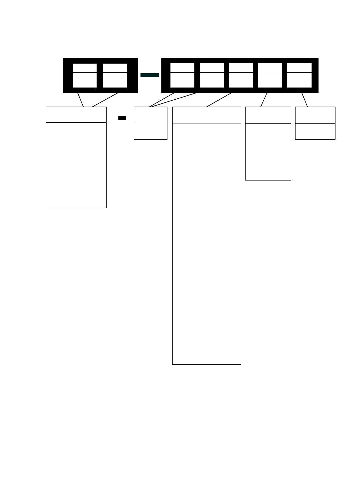
Numbering System
1st
Actuator Type
31 Spring opposed,
rolling diaphragm.
Air to close, fail
open action
32 Spring opposed,
rolling diaphragm,
Air to open, fail
closed action
33 Spring Diaphragm.
Air to extend action
only
2nd 3rd 4th 5th2nd
Body
Series
36
1st
3
6
Actuator Mounting
0 Undefined
1 Parallel to pipeline;
valve closes on stem
extension (air to close,
fail open)
2 Parallel to pipeline;
valve opens on stem
extension (air to open,
fail closed)
3 Vertical above
center; valve closes on
stem extension (air to
close, fail open)
4 Vertical above center;
valve opens on stem
extension (air to open,
fail closed)
5 Parallel to pipeline;
valve closes on stem
extension (air to close,
fail open)
6 Parallel to pipeline;
valve opens on stem
extension (air to open,
fail closed)
7 Vertical below
center; valve closes on
stem extension (air to
close, fail open)
8 Vertical below center;
valve opens on stem
extension (air to open,
fail closed)
Seal Type
1 MN-7 Seal Ring
2 316 SS Seal Ring
3 Heavy-Duty
Metal Seal Ring
(Optional)
Design
Series
5
Note:
Actuator sizes B and C are only supplied in positions 3, 4, 7 or 8.
36005 Series V-Max High Capacity V-Ported Control Ball Valve | 3
Page 4
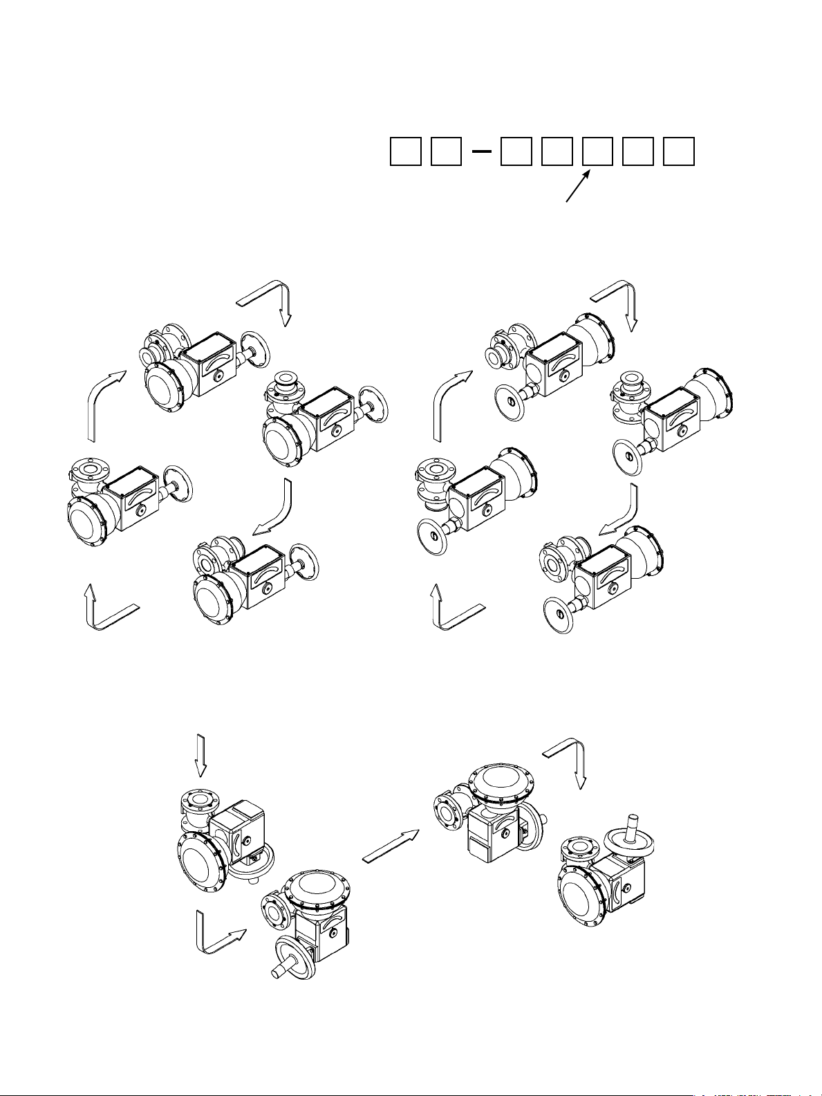
Actuator Mounting Guide
V-Max Valves
Actuator Model 33, Size AC
POS. 2
ATO
AIR TO
OPEN
POS. 4
ATO
POS. 8
ATO
3 X 3 6 X 0 5
Actuator position in relation to valve body
numbering system: 1 to 8.
POS. 1
ATC
POS. 3
POS. 7
POS. 7
ATO
ATC
AIR TO
CLOSE
ATC
POS. 6
ATO
Actuator Model 33, Sizes B and C
POS. 7
ATC
AIR TO
CLOSE
POS. 5
ATC
POS. 4
ATO
AIR TO
OPEN
POS. 3
ATC
POS. 8
ATO
4 | GE Oil & Gas
Page 5
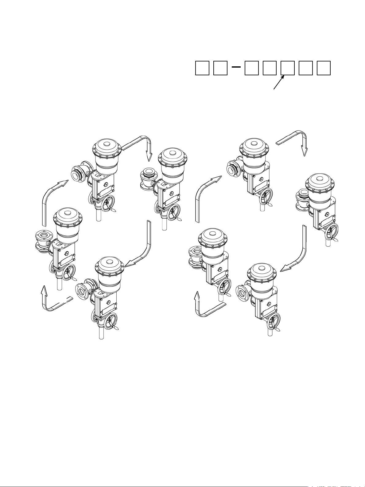
Actuator Mounting Guide
V-Max Valves
Actuator Models 31 and 32 (Size D)
POS. 4
ATO
AIR-TO-OPEN
ACTUATOR MODEL 32
SIZE D
POS. 2
ATO
3 X 3 6 X 0 5
Actuator position in relation to valve body
numbering system: 1 to 8.
POS. 3
ATC
AIR-TO-CLOSE
ACTUATOR MODEL 31
SIZE D
POS. 5
ATC
POS. 6
ATO
POS. 8
ATO
POS. 1
ATC
POS. 7
ATC
36005 Series V-Max High Capacity V-Ported Control Ball Valve | 5
Page 6

General Data
n Body
Type: Cast with integral bonnet
FlowDirection: Flowtoopen
Materials: Carbon steel
317 Stainless steel
Body Pressure
Rating:
EndConnections: F
n Trim
PlugType: D
Material: 317 Stainless steel, hard chrome plated
Seat Ring:
Materials:
Retainer: 317 Stainless steel
Capacity:
FlowCharacteristic:
Cv Ratio:
ANSI150or300Dependingonangerating
langed – bolts to ANSI Class 150 or 300 rated
flanges (1-inch to 12-inch)(DN25–300)
ual characterized, high capacity “V” contoured
segmented ball
MN-7,StandardMetalandHeavyDutyMetal
MN-7PolymericreinforcedPTFE
316 Stainless steel Standard Metal
Nitronic60HeavyDutymetal(OptionalNPS1-6)
High capacity ball valve
Equal percentage
Greater than 500:1
n Actuators
Spring-Opposed Diaphragm – Model 33
Size
AC:
B:
C:
Range
AC:
B:
C:
Air Connection:
Yoke: Castiron
Bearing: Sealed radial ball
Auxiliary Handwheel
AC:
B:
C:
Spring-Opposed Rolling Diaphragm – Model 31/32
SizeD:
RangeD:
Air Connection:
Yoke:
Bearing:
Manual Override:
30 in2 (194 cm2)
2.25-inch(57.2mm)Stroke
1-inch to 2-inchValves(DN25-50)
70 in2 (452 cm2)
2.625-inch(66.5mm)Stroke
2-inch to 4-inchValves(DN50-100)
140 in2 (903 cm2)
2.625-inch(66.5mm)Stroke
3-inch to 12-inch Valves(DN80-300)
7-15 psi
7-16 psi
9-16 psi
1/4 NPT
Optionalsoliddiskwithlockingnut
Optional rising stem push type
Optional rising stem push type
60 in2 (387 cm2)
4.00-inch(101.6mm)Stroke
6-inch to 12-inchValves(DN150-300)
12-28 psi
17-40 psi
29-68 psi
1/4 NPT
Cast iron
Sealed radial ball
Optionjackscrewgear
6 | GE Oil & Gas
Page 7

General Data
Standard Actuator Characteristics
Valve Size
in. DN in. mm
Shaft
Diameter
Model
Size Spring Range Effective Area
Standard Oversized
psi bar Sq. in. Sq. cm in. mm
Actuator
Stroke
1 25 0.62 15.7 33 AC 7-15 .48-1.03 30 194 2.250 57.2
1-1/2 40 0.62 15.7 33 AC 7-15 .48-1.03 30 194 2.250 57.2
Actuator
2 50
3 80
4 100
0.62 15.7 33 AC 7-15 .48-1.03 30 194 2.250 57.2
0.62 23.7 33 B 7-16 .48-1.10 70 452 2.625 66.5
0.93 23.7 33 B 7-16 .48-1.10 70 452 2.625 66.5
0.93 23.7 33 C 9-16 .62-1.10 140 903 2.625 66.5
0.93 23.7 33 B 7-16 .48-1.10 70 452 2.625 66.5
0.93 23.7 33 C 9-16 .62-1.10 140 903 2.625 66.5
1.2 30.5 33 C 9-16 .62-1.10 140 903 2.625 66.5
6 150
1.2 30.5 31/32 D 12-28 .83-1.93 60 387 4.000 101.6
1.2 30.5 31/32 D 17-40 1.17-2.76 60 387 4.000 101.6
1.2 30.5 31/32 D 29-68 2.00-4.69 60 387 4.000 101.6
1.2 30.5 33 C 9-16 .62-1.10 140 903 2.625 66.5
8 200
1.2 30.5 31/32 D 12-28 .83-1.93 60 387 4.000 101.6
1.2 30.5 31/32 D 17-40 1.17-2.76 60 387 4.000 101.6
1.2 30.5 31/32 D 29-68 2.00-4.69 60 387 4.000 101.6
1.37 34.8 33 C 9-16 .62-1.10 140 903 2.625 66.5
10 250
1.37 34.8 31/32 D 12-28 .83-1.93 60 387 4.000 101.6
1.37 34.8 31/32 D 17-40 1.17-2.76 60 387 4.000 101.6
1.37 34.8 31/32 D 29-68 2.00-4.69 60 387 4.000 101.6
1.37 34.8 33 C 9-16 .62-1.10 140 903 2.625 66.5
12 300
1.37 34.8 31/32 D 12-28 .83-1.93 60 387 4.000 101.6
1.37 34.8 31/32 D 17-40 1.17-2.76 60 387 4.000 101.6
1.37 34.8 31/32 D 29-68 2.00-4.69 60 387 4.000 101.6
Handwheel
Diameter
in.
mm
6.5
6.5
6.5
10
10
10
10
10
10
10
10
10
165
165
165
254
254
254
254
254
254
8
203
8
203
8
203
254
8
203
8
203
8
203
254
8
203
8
203
8
203
254
8
203
8
203
8
203
O-RING
Fugitive Emission Containment Package for
† Factory Mutual certified report
Zero Leakage
11
O-RING
Standard V-Max Packing Arrangement
EF Seal (Emission Free) Double O-Ring Seal
Packing Follower
Suitable for use in environmentally
sensitive applications, this economical
shaft seal solution to fugitive emissions
provides long-term, reliable, extremely low
emission performance without compromising control performance.
†
36005 Series V-Max High Capacity V-Ported Control Ball Valve | 7
Page 8

Temperature/Seat Leakage
Standard Metal Seal Ring Temperature Limitations
A strain hardened 316 stainless steel seal ring is an available
option when the MN-7 Seal is not suitable. Seat leakage is per
ANSI /FCI 70.2 Class IV. The metal seal ring can be used with
either MN-7 lined bearings or the optional solid metal bearings.
The fluid temperature is limited to 425°F (218°C) when using the
MN-7 lined. A high temperature package consisting of metal seal
ring, bearings and flexible graphite packing
elevates fluid temperature limitations to 600°F (316°C)
maximum or ANSI working pressure and temperature
limitations. For use in lubricated service only.
MN-7 Seal Ring Temperature Limitations
The standard MN-7 seal ring provides tight, ANSI/FCI 70.2
Class VI seat leakage. Pressure and temperature ratings of this
design are limited as shown in the chart below as well as those
shown in the corresponding pressure drop tables.
(Optional) Heavy Duty Metal Seal Ring (Bi-directional Flow)
A solid Heavy Duty Metal seat ring is available (NPS 1-6) when
the MN-7 or Standard Metal Seal ring is not suitable. The Heavy
Duty Seat ring must be used with solid metal bearings. Fluid
temperature is limited to 500°F (260°C) due to the material of
the radial seal. Seat leakage is per ANSI/FCI 70.2 Class IV.
400
300
200
Temperature °F
100
0
-50
100 200 300 400 500 600 700 800
(6.89) (13.79) (20.68) (27.58) (34.47) (41.37) (48.26) (55.16)
Temperature °F
1
3
2
Pressure Drop psi (bar)
1
1 Zone of maximum temperature limits
2
2 Zone of maximum pressure limits
3
3 Zone of maximum interactive pressure/temperature limits
200
150
100
50
0
-45
Temperature °C
8 | GE Oil & Gas
Page 9

CV and FL versus Travel
Flow Direction: Flow to Open
Flow Characteristics: Equal Percentage
ANSI Class 150 and 300
Valve Sizes: 1 to 12-inch (DN 25-300)
Percent (%) of Max.
Opening
Percent (%) of Max.
C
V
F
L
Valve Size
in DN
1 25 0.11 0.54 1.2 2.9 5.2 8.3 12.1 17 26 40 55
1-1/2 40 0.25 1.2 2.7 6.5 12 19 28 39 58 90 125
2 50 0.34 1.7 3.7 8.8 16 26 37 54 79 122 170
3 80 0.88 4.3 9.5 23 42 66 97 139 205 317 440
4 100 1.48 7.3 16 38 70 111 163 233 344 533 740
6 150 2.50 12 27 65 119 188 275 394 581 900 1250
8 200 3.72 18 40 97 177 279 409 586 865 1339 1860
10 250 6.0 30 65 157 287 453 664 951 1404 2174 3020
12 300 8.8 43 95 229 418 660 968 1386 2046 3168 4400
10 15 20 30 40 50 60 70 80 90 100
0.20% 0.98% 2.15% 5.2% 9.5% 15.0% 22.0% 31.5% 46.5% 72.0% 100.0%
0.92 0.91 0.90 0.89 0.87 0.83 0.80 0.76 0.72 0.67 0.60
Rated C
V
36005 Series V-Max High Capacity V-Ported Control Ball Valve | 9
Page 10

Materials of Construction
27
5
28
12
25 24 23 22 20 21 28 29
5
8
30
26 19 17
31
3
3
3
32
32
8
6
8
7
16
15
11
14
12
2
1
4
10
3
9
10 | GE Oil & Gas
Page 11

Materials of Construction
Carbon Steel Construction
Ref.
No
1 Body Flanged ASTM A216 Gr WCB Carbon Steel
2 Ball Plug ASTM A351 Gr CG8M Type 317, Hard Chromium Plated
Retainer Standard (ISA S75.04)
3
Retainer Extended (ANSI B16.10)
4 Gasket (retainer body) Flexible Graphite
5 Stem Shaft
6 Backup Ring (flat metal seat) ASTM A240 Type 317L Stainless Steel
7 Gasket (flat metal seat) 316 Stainless Steel/Flexible Graphite
Seat Ring Flexible Metal ASTM A66 1/4 Hard Strain Hardened 316 Stainless Steel Sheet
8
Seat Ring MN-7
Seat Ring Heavy Duty Rigid Nitronic 60 Stainless Steel
9 Slot Button Head Screw Carbon Steel Plated
10 Flat Washer Carbon Steel Plated
11 Pin Shaft
12 Cap Screw, End Flange ASTM A193 Gr B8
14 End Flange ASTM A36 Plated
15 Gasket Pin Shaft Nitrile Bound Acrylic
16 Lower Bushing
17 Upper Bushing
19 Packing Set
20 Packing Follower ASTM A582 Type 303 St. St.
21 O-Ring Viton
22 O-Ring Viton
23 Packing Box Flange ASTM A216 Gr WCC Plated
24 Nut, Packing Flange Stud ASTM A194 Gr 8
25 Stud, Packing Flange Alloy Steel ASTM A193 Gr B8
26 Stud, Bonnet Alloy Steel ASTM A193 Gr B8
Safety Pin ASTM A479 Type 316
27
Packing Adapter ASTM A479 Type 316
28
Shaft Ring ASTM A564 Gr 632
29
Radial Seal, HD Seat GFP Graphite Fiber Reinforced PTFE Seal, Hastelloy C276 Spring
30
Wave Spring, HD Seat Inconel X-750 Material (AM-5699) Precipitation Hardened
31
Seat Support Ring, Downstream ASTM A240 Type 317L Stainless Steel
32
Ref.
No
Temperature Range
Description Standard Materials
Temperature Range
-20oF +425oF +450oF +500oF +600oF
-29°C +218°C +232°C +260°C +316°C
∆∆ ∆∆∆
ASTM A351 Gr CG8M Type 317
ASTM A564 Gr 630 H1075
(NACE) Nitronic 50
ASTM A564 Gr 630 H1075
Nitronic 50
316 Stainless Steel/MN-7 Lined
Stellite
316 Stainless Steel/MN-7 Lined
Stellite
Crane 285K - TFE Aramid Core
Flexible Graphite
∆
-20oF +425oF +450oF +500oF +600oF
-29°C +218°C +232°C +260°C +316°C
∆ ∆ ∆
36005 Series V-Max High Capacity V-Ported Control Ball Valve | 11
Page 12

Materials of Construction
Stainless Steel Construction
Ref.
No
1 Body Flanged ASTM A351 Gr CG8M Type 317
2 Ball Plug ASTM A351 Gr CG8M Type 317, Hard Chromium Plated
Retainer Standard (ISA S75.04)
3
Retainer Extended (ANSI B16.10)
4 Gasket (retainer body) Flexible Graphite
5 Stem Shaft
6 Backup Ring (flat metal seat) ASTM A240 Type 317L Stainless Steel
7 Gasket (flat metal seat) 316 Stainless Steel/Flexible Graphite
Seat Ring Flexible Metal ASTM A66 1/4 Hard Strain Hardened 316 Stainless Steel Sheet
8
Seat Ring MN-7
Seat Ring Heavy Duty Rigid Nitronic 60 Stainless Steel
9 Slot Button Head Screw Carbon Steel Plated
10 Flat Washer Carbon Steel Plated
11 Pin Shaft
12 Cap Screw, End Flange ASTM A193 Gr B8
14 End Flange ASTM A36 Plated
15 Gasket Pin Shaft Nitrile Bound Acrylic
16 Lower Bushing
17 Upper Bushing
19 Packing Set
20 Packing Follower ASTM A582 Type 303 St. St.
21 O-Ring Viton
22 O-Ring Viton
23 Packing Box Flange ASTM A216 Gr WCC Plated
24 Nut, Packing Flange Stud ASTM A194 Gr 8
25 Stud, Packing Flange Alloy Steel ASTM A193 Gr B8
26 Stud, Bonnet Alloy Steel ASTM A193 Gr B8
Safety Pin ASTM A479 Type 316
27
Packing Adapter ASTM A479 Type 316
28
Shaft Ring ASTM A564 Gr 632
29
Radial Seal, HD Seat GFP Graphite Fiber Reinforced PTFE Seal, Hastelloy C276 Spring
30
Wave Spring, HD Seat Inconel X-750 Material (AMS 5699) Precipitation Hardened
31
Seat Support Ring, Downstream 317 Stainless Steel
32
Ref.
No
Temperature Range
Description Standard Materials
Temperature Range
-50oF +425oF +450oF +500oF +600oF
-46°C +218°C +232°C +260°C +316°C
∆∆ ∆∆∆
ASTM A351 Gr CG8M Type 317
Nitronic 50 (Standard)
ASTM A564 Gr 630 H1075 (Optional)
Nitronic 50 (Standard)
ASTM A564 Gr 630 H1075 (Optional)
316 Stainless Steel/MN-7 Lined
Stellite
316 Stainless Steel/MN-7 Lined
Stellite
Crane 285K - TFE Aramid Core
Flexible Graphite
∆
-50oF +425oF +450oF +500oF +600oF
-46°C +218°C +232°C +260°C +316°C
∆ ∆ ∆
12 | GE Oil & Gas
Page 13

Materials of Construction
Carbon Steel NACE Construction — Complies with NACE MR0103-2003
Ref.
No
1 Body Flanged
2 Ball Plug ASTM A351 Gr CG8M Type 317, Hard Chromium Plated
Retainer Standard (ISA S75.04)
3
Retainer Extended (ANSI B16.10)
4 Gasket (retainer body) Flexible Graphite
5 Stem Shaft Nitronic 50
6 Backup Ring (flat metal seat) ASTM A240 Type 317L Stainless Steel
7 Gasket (flat metal seat) 316 Stainless Steel/Flexible Graphite
Seat Ring Flexible Metal ASTM A66 1/4 Hard Strain Hardened 316 Stainless Steel Sheet
Seat Ring MN-7
8
Seat Ring Heavy Duty Rigid Nitronic 60 Stainless Steel
9 Slot Button Head Screw Carbon Steel Plated
10 Flat Washer Carbon Steel Plated
11 Pin Shaft Nitronic 50
12 Cap Screw, End Flange ASTM A193 Gr B8
14 End Flange ASTM A36 Plated
15 Gasket Pin Shaft Nitrile Bound Acrylic
16 Lower Bushing
17 Upper Bushing
19 Packing Set
20 Packing Follower ASTM A582 Type 303 St. St.
21 O-Ring Viton
22 O-Ring Viton
23 Packing Box Flange ASTM A216 Gr WCC Plated
24 Nut, Packing Flange Stud ASTM A194 Gr 8
25 Stud, Packing Flange Alloy Steel ASTM A193 Gr B8
26 Stud, Bonnet Alloy Steel ASTM A193 Gr B8
Safety Pin ASTM A479 Type 316
27
Packing Adapter ASTM A479 Type 316
28
Shaft Ring ASTM A564 Gr 632
29
Radial Seal, HD Seat GFP Graphite Fiber Reinforced PTFE Seal, Hastelloy C276 Spring
30
Wave Spring, HD Seat Inconel X-750 Material (AMS 5699) Precipitation Hardened
31
Seat Support Ring, Downstream ASTM A240 Type 317L Stainless Steel
32
Ref.
No
Temperature Range
Description Standard Materials
Temperature Range
-50oF -20oF +425oF +450oF +500oF +600oF
-46°C -29°C +218°C +232°C +260°C +316°C
∆∆∆ ∆∆∆
ASTM A216 Gr WCB Carbon Steel
ASTM A351 Gr CG8M Type 317
ASTM A351 Gr CG8M Type 317
316 Stainless Steel/MN-7 Lined
Stellite
316 Stainless Steel/MN-7 Lined
Stellite
Crane 285K - TFE Aramid Core
Flexible Graphite
∆ ∆ ∆ ∆ ∆
-50oF -20oF +425oF +450oF +500oF +600oF
-46°C -29°C +218°C +232°C +260°C +316°C
36005 Series V-Max High Capacity V-Ported Control Ball Valve | 13
Page 14

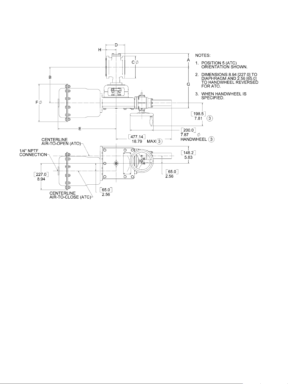
Dimensions
Actuator Model 33, Size AC – inches [millimeters]
Actuator Model 33, Size B and C – inches [millimeters]
14 | GE Oil & Gas
Page 15

Dimensions
Actuator Model 33, Sizes AC, B and C (inches)
Valve
Size
in. DN Size
Actuator
Size
Sq.
In.
ANSI
150
A
ANSI
300
(1)
C
B
ANSI
150
ANSI
300
Face-to-Face
D
Standard
ISA
(2)
S75.04
Optional
ASME
(3)
B16.10
E F G
Center-to-Face
H
Standard
S75.04
ISA
(2)
Optional
ASME
B16.10
1 25 AC 30 2.74 2.74 8.06 4.25 4.88 4.00 5.00 10.70 8.50 10.53 2.12 3.12
1.5 40 AC 30 3.13 4.08 8.33 5.00 6.12 4.47 6.49 10.70 8.50 10.80 2.43 4.46
AC 30 3.92 5.05 8.74 6.00 6.50 4.93 7.01 10.70 8.50 11.21 2.56 4.64
2 50
B 70 3.92 5.05 8.52 6.00 6.50 4.93 7.01 11.45 13.00 11.21 2.56 4.64
B 70 4.64 4.64 10.24 7.50 8.25 6.54 8.00 11.45 13.00 12.93 3.59 5.06
3 80
C 140 4.64 4.64 10.24 7.50 8.25 6.54 8.00 15.07 17.50 12.93 3.59 5.06
B 70 5.48 5.48 10.87 9.00 10.00 7.61 9.00 11.45 13.00 13.56 3.95 5.50
4 100
C 140 5.48 5.48 10.87 9.00 10.00 7.61 9.00 15.07 17.50 13.56 3.95 5.50
6 150 C 140 6.76 6.76 12.09 11.00 12.50 8.99 10.52 15.07 17.50 14.78 4.85 6.37
8 200 C 140 7.88 7.88 13.81 13.50 15.00 9.59 11.50 15.07 17.50 16.50 5.03 6.95
10 250 C 140 9.46 9.46 15.75 16.00 17.50 11.69 13.02 15.07 17.50 18.44 6.09 7.42
12 300 C 140 10.63 10.63 16.92 19.00 20.50 13.33 14.00 15.07 17.50 19.61 7.52 8.19
Actuator Model 33, Sizes AC, B and C (millimeters)
(3)
Valve
Size
Actuator
Size
A
(1)
C
B
in. DN Size
1 25 AC
1.5 40 AC
AC
Sq. cmANSI
150
194 69.60 69.60 204.72 107.95 123.95 101.60 127.00 271.78 215.90 267.46 53.85 79.25
194 79.50 103.63 211.58 127.00 155.45 113.54 164.85 271.78 215.90 274.32 61.72 113.28
194 99.57 128.27 222.00 152.40 165.10 125.22 178.05 271.78 215.90 284.73 65.02 117.86
ANSI
300
ANSI
150
ANSI
300
2 50
B
452 99.57 128.27 216.41 152.40 165.10 125.22 178.05 290.83 330.20 284.73 65.02 117.86
452 117.86 117.86 260.10 190.50 209.55 166.12 203.20 290.83 330.20 328.42 91.19 128.52
B
3 80
C
903 117.86 117.86 260.10 190.50 209.55 166.12 203.20 382.78 444.50 328.42 91.19 128.52
452 139.19 139.19 276.10 228.60 254.00 193.29 228.60 290.83 330.20 344.42 100.33 139.70
B
4 100
C
903 139.19 139.19 276.10 228.60 254.00 193.29 228.60 382.78 444.50 344.42 100.33 139.70
6 150 C
8 200 C
10 250 C
12 300 C
Notes:
1. Conforms to ASME/ANSI Standard B16.5 - 1996 “Pipe Flanges and Flange Fittings.”
2. Conforms to ISA Standard S75.04.
3. Conforms to ASME Standard B16.10 - 1992 (formerly ANSI Standard B16.10 - 1973)
Short Pattern Ball. Available for ANSI 150 Class Valves ONLY.
903 171.70 171.70 307.09 279.40 317.50 228.35 267.21 382.78 444.50 375.41 123.19 161.80
903 200.15 200.15 350.77 342.90 381.00 243.59 292.10 382.78 444.50 419.10 127.76 176.53
903 240.28 240.28 400.05 406.40 444.50 296.93 330.71 382.78 444.50 468.38 154.69 188.47
903 270.00 270.00 429.77 482.60 520.70 338.58 355.60 382.78 444.50 498.09 191.01 208.03
Face-to-Face
D
Standard
ISA
(2)
S75.04
Optional
ASME
(3)
B16.10
E F G
Center-to-Face
H
Standard
S75.04
ISA
(2)
Optional
ASME
B16.10
(3)
36005 Series V-Max High Capacity V-Ported Control Ball Valve | 15
Page 16
Dimensions
Actuator Model 31/32, Size D – inches [millimeters]
16 | GE Oil & Gas
Page 17

Dimensions
Actuator Model 31/32, Size D (inches)
Valve
Size
in. DN Size
Actuator
Size
Sq.
In.
ANSI
150
A
ANSI
300
(1)
C
B
ANSI
150
ANSI
300
Face-to-Face
D
Standard
ISA
(2)
S75.04
Optional
ASME
(3)
B16.10
E F G
Center-to-Face
H
Standard
S75.04
ISA
(2)
Optional
ASME
B16.10
3 80 D 60 4.64 4.64 12.12 7.50 8.25 6.54 8.00 19.78 12.75 13.88 3.59 5.06
4 100 D 60 5.48 5.48 12.75 9.00 10.00 7.61 9.00 19.78 12.75 14.51 3.95 5.50
6 150 D 60 6.76 6.76 14.06 11.00 12.50 8.99 10.52 19.78 12.75 15.82 4.85 6.37
8 200 D 60 7.88 7.88 15.69 13.50 15.00 9.59 11.50 19.78 12.75 17.45 5.03 6.95
10 250 D 60 9.46 9.46 17.63 16.00 17.50 11.69 13.02 19.78 12.75 19.39 6.09 7.42
12 300 D 60 10.63 10.63 18.80 19.00 20.50 13.33 14.00 19.78 12.75 20.56 7.52 8.19
Actuator Model 31/32, Size D (millimeters)
Valve
Size
in. DN Size
3 80
4 100
6 150
8 200
10 250
12 300
Actuator
Size
Sq. cmANSI
150
A
ANSI
300
(1)
C
B
ANSI
150
ANSI
300
Face-to-Face
D
Standard
ISA
(2)
S75.04
Optional
ASME
(3)
B16.10
E F G
Center-to-Face
H
Standard
S75.04
ISA
(2)
Optional
ASME
B16.10
D 387 117.86 117.86 307.85 190.50 209.55 166.12 203.20 502.41 323.85 352.55 91.19 128.52
D 387 139.19 139.19 323.85 228.60 254.00 193.29 228.60 502.41 323.85 368.55 100.33 139.70
D 387 171.70 171.70 357.12 279.40 317.50 228.35 267.21 502.41 323.85 401.83 123.19 161.80
D 387 200.15 200.15 398.53 342.90 381.00 243.59 292.10 502.41 323.85 443.23 127.76 176.53
D 387 240.28 240.28 447.80 406.40 444.50 296.93 330.71 502.41 323.85 492.51 154.69 188.47
D 387 270.00 270.00 477.52 482.60 520.70 338.58 355.60 502.41 323.85 522.22 191.01 208.03
(3)
(3)
Notes:
1. Conforms to ASME/ANSI Standard B16.5 - 1996 “Pipe Flanges and Flange Fittings.”
2. Conforms to ISA Standard S75.04.
3. Conforms to ASME Standard B16.10 - 1992 (formerly ANSI Standard B16.10 - 1973)
Short Pattern Ball. Available for ANSI 150 Class Valves ONLY.
36005 Series V-Max High Capacity V-Ported Control Ball Valve | 17
Page 18

Assembly Weights
Valve and Actuator Assembly Weights (without Manual Override)
Valve Size Actuator
in. DN Model Size lbs Kg lbs Kg lbs Kg lbs Kg
1 25 33 AC 50 22 53 24 50 23 7 3
1.5 40 33 AC 54 24 61 27 56 25 7 3
2 50
3 80
4 100
6 150
33 AC 60 27 81 37 63 29 7 3
33 B 101 46 122 55 103 47 27 12
33 B 124 56 134 61 128 58 27 12
33 C 182 82 192 87 186 84 27 12
31/32 D 227 103 237 107 231 105 12 5
33 B 147 67 166 75 152 69 27 12
33 C 205 93 224 101 210 95 27 12
31/32 D 250 113 269 122 255 116 12 5
33 C 250 114 288 131 260 118 27 12
31/32 D 295 134 333 151 305 138 12 5
Standard ISA S75.04 Face-to-Face
ANSI Class 150 Flanged ANSI Class 300 Flanged
Optional ASME B16.10
Face-to-Face
ANSI Class 150
Flanged ONLY
Manual
Override
Add to Valve /
Actuator Weight
8 200
10 250
12 300
33 C 303 137 359 163 326 148 27 12
31/32 D 348 158 404 183 371 168 12 5
33 C 393 178 416 189 480 217 27 12
31/32 D 438 199 461 209 525 238 12 5
33 C 520 236 540 245 642 291 27 12
31/32 D 565 256 585 265 687 312 12 5
18 | GE Oil & Gas
Page 19

36005 Series V-Max High Capacity V-Ported Control Ball Valve | 19
Page 20

DIRECT SALES OFFICE LOCATIONS
BELGIUM
Phone: +32-2-344-0970
Fax: +32-2-344-1123
BRAZIL
Phone: +55-11-2146-3600
Fax: +55-11-2146-3610
CHINA
Phone: +86-10-8486-4515
Fax: +86-10-8486-5305
FRANCE
Courbevoie
Phone: +33-1-4904-9000
Fax: +33-1-4904-9010
GERMANY
Ratingen
Phone: +49-2102-108-0
Fax: +49-2102-108-111
INDIA
Mumbai
Phone: +91-22-8354790
Fax: +91-22-8354791
New Delhi
Phone: +91-11-2-6164175
Fax: +91-11-5-1659635
ITALY
Phone: +39-081-7892-111
Fax: +39-081-7892-208
JAPAN Chiba
Phone: +81-43-297-9222
Fax: +81-43-299-1115
KOREA
Phone: +82-2-2274-0748
Fax: +82-2-2274-0794
MALAYSIA
Phone: +60-3-2161-0322
Fax: +60-3-2163-6312
MEXICO
Phone: +52-5-310-9863
Fax: +52-5-310-5584
THE NETHERLANDS
Phone: +0031-15-3808666
Fax: +0031-18-1641438
RUSSIA
Veliky Novgorod
Phone: +7-8162-55-7898
Fax: +7-8162-55-7921
Moscow
Phone: +7 495-585-1276
Fax: +7 495-585-1279
SAUDI ARABIA
Phone: +966-3-341-0278
Fax: +966-3-341-7624
SINGAPORE
Phone: +65-6861-6100
Fax: +65-6861-7172
SOUTH AFRICA
Phone: +27-11-452-1550
Fax: +27-11-452-6542
SOUTH and CENTRAL
AMERICA and the CARIBBEAN
Phone: +55-12-2134-1201
Fax: +55-12-2134-1238
SPAIN
Phone: +34-93-652-6430
Fax: +34-93-652-6444
UNITED ARAB EMIRATES
Phone: +971-4-8991-777
Fax: +971-4-8991-778
UNITED KINGDOM
Wooburn Green
Phone: +44-1628-536300
Fax: +44-1628-536319
UNITED STATES
Massachusetts
Phone: +1-508-586-4600
Fax: +1-508-427-8971
Corpus Christi, Texas
Phone: +1-361-881-8182
Fax: +1-361-881-8246
Deer Park, Texas
Phone: +1-281-884-1000
Fax: +1-281-884-1010
Houston, Texas
Phone: +1-281-671-1640
Fax: +1-281-671-1735
* Trademark of G eneral Elect ric Company
Other company names and product names used in this document are the registered trademarks
or trademarks of their respective owners.
© 2012 General El ectric Comp any. All rights re served.
GEA19375 12/2012
 Loading...