

Page 1
The Mini-Eegor™ bender was designed with personal safety in mind. Nevertheless, when a
machine is powered with ten tons of force, certain precautions must be exercised to keep that force under control at
all times.
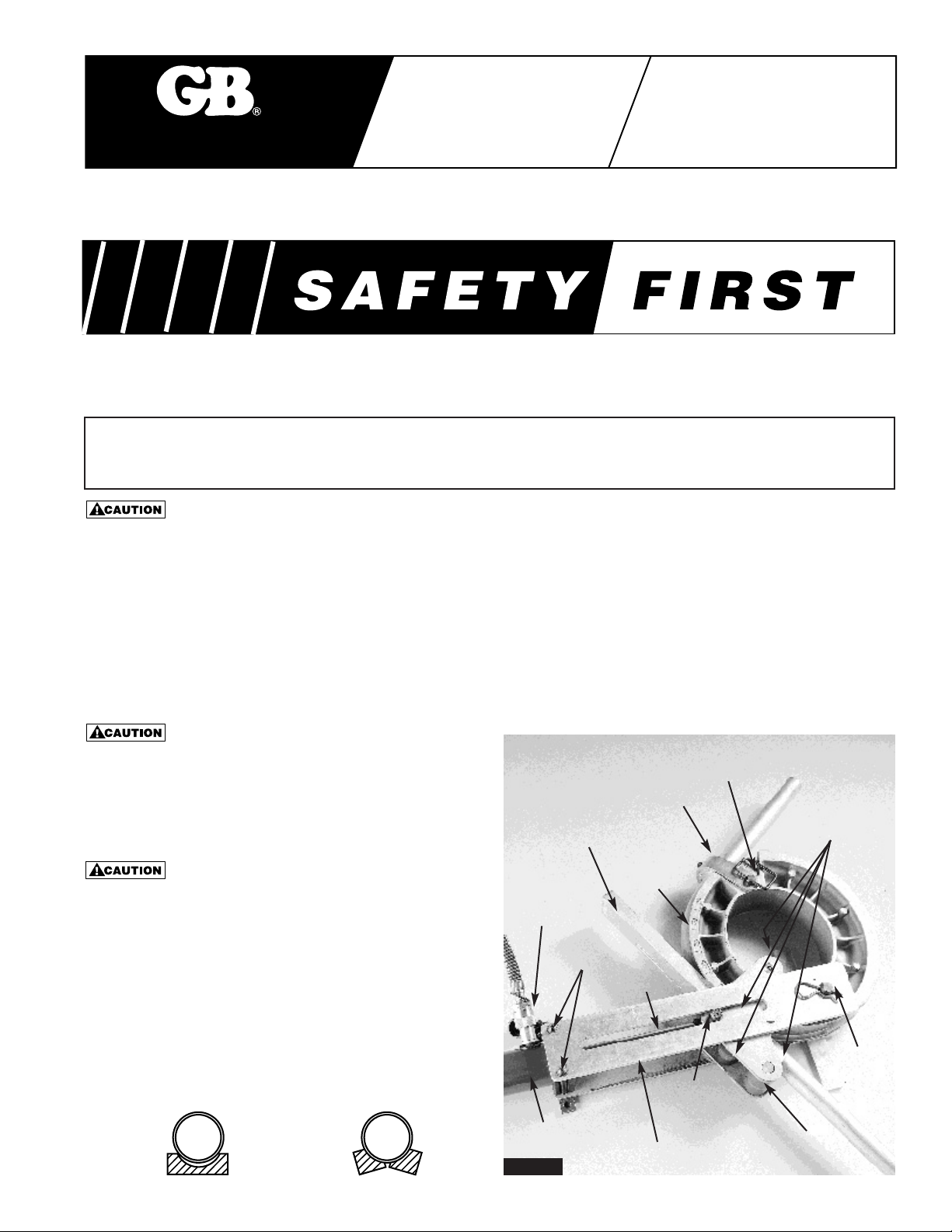
Fully Assemble All Load-bearing Pins:
Unless all pins are fully engaged in their respective sockets, the resulting misapplied loads can deform and destroy
the bender, with associated danger to attending personnel.
1. All four axles of the compression roller plate assembly must project through, or be flush with, both plates.
2. The top aluminum load arm must be fully seated so that three pins project through it with the chamfered roller
engaging the slot.
3. The U-strap pin must seat on its handle.
Do Not Attempt to Use Damaged Components:
Should any part of the Mini-Eegor™ bender become
damaged for any reason, replace it before resuming
bending operations. Failure to do so may jeopardize other
components and personal safety as well.
Keep Clear of Possible Pinch Points:
Relative motion between bender components could severely
pinch fingers or cut any objects wedged in between.
Use Standard Precautions with Hydraulic Hoses:
Couplings must be fully engaged to permit free flow of oil.
Be alert to avoid developing sharp bends or pinching
of hose.
Bend Only Conduit that Fits Freely into Shoe Grooves:
Oversize pipe that hangs up on the groove edges can
sometimes split a shoe.
Gardner
Bender
IMPORTANT RECEIVING INSTRUCTIONS: Visually inspect all components for shipping damage. If any shipping
damage is found, notify carrier at once. Shipping damage is NOT covered by warranty. The carrier is responsible for
all repair or replacement costs resulting from damage in shipment.
Instruction
Sheet
Mini-Eegor™
Hydraulic Bender
IMPORTANT USER SAFETY AND PROTECTION: In setting up systems to fit your operations, care must be taken
to select the proper components and design to insure appropriate integration with your operations and existing
equipment and that all safety measures have been taken to avoid the risk of personal injury and property damage
from your application or system.
GB ELECTRICAL CANNOT BE RESPONSIBLE FOR DAMAGE OR INJURY CAUSED BY UNSAFE USE,
MAINTENANCE OR APPLICATION OF ITS PRODUCTS. Please contact GB Electrical for guidance when you are
in doubt as to the proper safety precautions to be taken in designing and setting up your particular application.
To Protect Your Warranty, Use Only Enerpac Hydraulic Oil
Hydraulic
Coupling
Follow Bar
Load Arm Pins
Hydaulic Cylinder
Rod Eye
Chamfered
Roller
U-strap
Top
Load Arm
Top Compression
Roller Plate
U-strap Pin
Load
Arm Pin
4 Compression
Roller Axles
Bending
Shoe
Mini-Eegor™ Bender
Figure 1
This: Results in this:
Page 2
2
Instructions
Description
The Mini-Eegor™ conduit bender hydraulically bends
Electrical Metallic Tubing (i.e., Thinwall or EMT),
Intermediate Metal Conduit (IMC), Rigid Aluminum and
Rigid Steel Conduit, all with the same shoe, in sizes 1”,
11⁄4”, 11⁄2”, and 2”. Any angle up to and including 90°
can be quickly bent in one set-up. Upon completion of
the operation, the bent pipe is hydraulically stripped
from the bending shoe. The Mini-Eegor™ is available
with a variety of hydraulic pumps, and can be purchased
without the 1” bending capability at a reduced cost.
Operation
1. Select a work location with a reasonably flat surface
and, preferably, free of sand, gravel, or other debris
that might interfere with the bending operation.
(See Figure 2.)
2. Select a bending shoe and follower shoe (or follow
bar), if required, for the size pipe to be bent. Follow
bars are required for 2” IMC and rigid conduit and for
2”, 1
1
⁄2” and 11⁄4” EMT. All shoes are identified with
the nominal conduit size marked on the shoe. It is
recommended, particularly when preparing to bend
unfamiliar brands of conduit, to first lay the pipe in
the groove of the shoe and follow bar to ensure that
the pipe fits without hanging up on the edges.
Note that each Mini-Eegor™ bending shoe has two
grooves, one for EMT and the other for IMC and rigid
conduit. The conduit type is engraved in its
corresponding shoe side to indicate the side you will use
when bending EMT, or IMC and rigid conduit. The
appropriate shoe side will make contact with the conduit
during bending. For bending the other type of conduit,
just flip the shoe over.
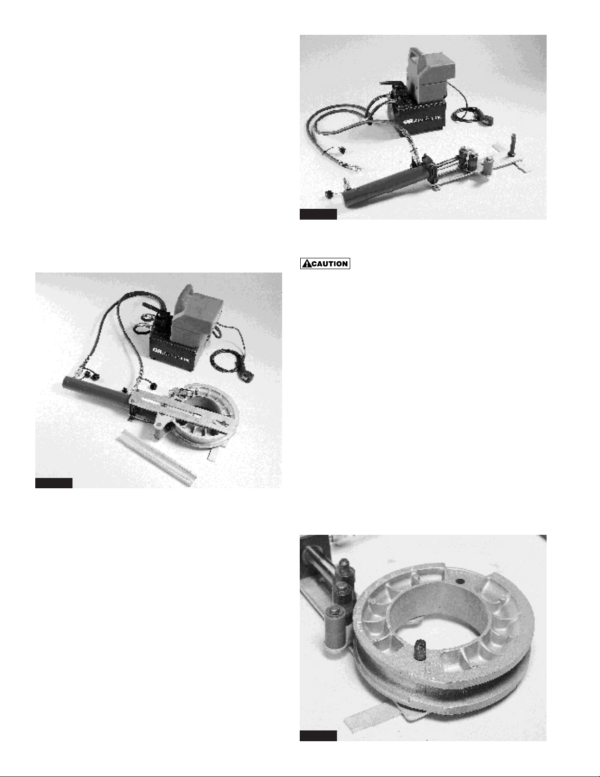
3. Connect the hydraulic hoses between the pump and
cylinder ports (see Figure 3).
Fully engage the couplers, and then be sure that the
threaded coupler sleeves bottom against their seats.
Failure to fully engage the couplers could result in oil
entrapment in one end of the cylinder which could
seriously over-pressurize the cylinder, resulting in
reduced product life and safety.
4. Lift off the top aluminum load arm and the top plate
of the roller assembly. The bending shoe must
swivel on the pivot pin and rest on the lower roller
plate close to the steel rollers.
5. Extend the cylinder plunger hydraulically until the
lower roller plate approaches the pivot pin closely
enough to support one end of the bending shoe.
6. Engage the bending shoe over the pivot pin (see
Figure 4).
Note: The 1” bending shoe (BZ259) has two pivot
holes. Be sure the pivot pin engages the hole
marked for the type conduit to be bent.
Otherwise, the shoe will not bend a full 90° bend.
Figure 2
Figure 3
Figure 4
Page 3

3
7. The bending shoe must swivel in a clockwise
direction about the pivot pin when bending pipe.
Therefore, when assembling the bender, swivel the
shoe counter clockwise to bring it into contact with
the steel rollers so that the top roller plate can be
assembled (see Figure 5).
8. Assemble the top roller plate sub-assembly (see
Figure 6). For easy assembly of the top roller plate
sub-assembly, first loosely engage the chamfered
roller atop the cylinder rod eye pin in its socket; then
engage the axle of the large steel roller into its
socket in the lower roller plate. The remaining axles
will then readily engage their respective sockets to
seat flush with the top plate surface.
Figure 7 illustrates the wrong way to assemble the
roller plates. The axle of the large steel roller inside of
the bending shoe (at right) is not seated in the lower
roller plate, as the gap under the roller indicates. Any
attempt to bend pipe with the roller plates in this position
will destroy the bender.
9. The top aluminum load arm can then be assembled
over the three projecting support pins and the
chamfered roller. Engage the pivot pin and
chamfered roller first, then lift lightly under the end
of the cylinder and the load arm will slip down over
the remaining pins in the cylinder support block
(see Figure 8).
Figure 8
Figure 5
Figure 6
Figure 7
The gap here indicates that the
axle is not seated in the lower
roller plate. Do not proceed with
bending until all axles are
properly engaged.
Do not attempt to bend pipe until all load bearing pins
are fully engaged in their respective sockets, or serious
damage may result.
10. Insert the pipe to be bent into the groove between
the rollers and the bending shoe (see Figure 9).
Page 4

4
4
12. The follow bar is next inserted between the pipe
and the rollers. The cylinder plunger should be fully
retracted, but not to the extent of locking up the
assembly. If a little slack is allowed so that the
bending shoe and frame components are loose, the
“start” end of the follow bar (with the ramp) can be
readily inserted until it contacts the U-strap.
11. The U-strap must now be assembled to clamp the
pipe to the bending shoe. Hydraulically retract the
cylinder plunger until the U-strap hole in the shoe
approaches the edge of the aluminum load arm
(bender frame). The greatest clearance for easiest
assembly exists when the U-strap hole is right next
to the load arm edge. Assemble the correct size
insert into the U-strap for the size pipe to be bent.
(No insert is required for the 2” size.) Assemble the
U-strap assembly over the conduit onto the shoe,
and insert the U-strap into the aligned holes until it
bottoms on the handle. Lay the handle flat against
the U-strap and oriented away from the bender
frame so that it will not contact the frame while
bending (see Figure 10).
13. The end of the follow bar must be inserted at least
as far as the rollers at the cylinder rod eye so that
all of the short steel rollers can ride on the follow
bar pressure surface (see Figure 11).
14. You are now ready to bend pipe. Actuate the
cylinder, and observe that the follow bar moves
together with the pipe as it passes through the roller
assembly (see Figure 12). If the follow bar does not
move, it has not been inserted far enough.
Immediately retract the cylinder plunger and re-seat
the follow bar so that it will move with the pipe.
15. Actuate the cylinder until the desired angle of bend
is achieved, as indicated by the bend angle scale
on the bending shoe as it emerges from under the
edge of the upper roller plate. A maximum 90°
bend is obtainable on all sizes and types of conduit
in one set-up with the Mini-Eegor™ (see Figure 13).
Figure 9
Figure 10
Figure 11
Figure 12
Insert pipe here
To prevent U-strap from damaging
conduit, be sure U-strap is completely
against the shoe prior to bending.
The end of the follow bar
must project past the contact
line of the short steel rollers.
Page 5

5
Note: Because electrical conduit varies somewhat from
lot to lot in size, material composition, hardness,
wall thickness, etc..., a general-purpose bend
angle scale cannot be established with any great
precision. Preparatory to doing any precision
bending, it is recommended that a trial bend be
made on each lot of conduit to establish a
correction value to be made to the bend angle
scale. The precise angle can then be marked on
the bending shoe at the leading edge of the
roller plate.
Maintenance of the Mini-Eegor™ Bender
Aside from conventional care of the hydraulic
components, very little maintenance of the Mini-Eegor™
bender is required. Removing sand and dirt from
grooves and moving parts will extend the bender life
and facilitate ease of operation. Lubricate rollers, when
needed, with molybdenum disulfide paste only (such as
Dow Corning’s Molykote No. G-n paste, or equivalent).
Note:
Graphite formulations are not equivalent lubrication.
Figure 13
Picture of a Finished Bend
Figure 14
16. To remove bent conduit from the Mini-Eegor™
upon completion of the bend, retract the cylinder
plunger, pull out the follow bar, and lift out the pipe (see
Figure 14).
Make sure follow bar doesn’t slide forward during
retraction.
Note: Removal of bent pipe may be easier if the
U-strap is first removed. Just pull the pin.
17. Offsets or other more complicated bends may
justify lifting off the top aluminum load arm and the
top roller plate before removing the pipe. Then,
just swivel the shoe away from the pipe for
easiest removal.
90° Stub-up and Kick Bend Instructions
Diagonal Distance (D) Chart
Rise
Bend Angle
(H) 15° 30° 45° 60° 90°
27
3
⁄4 42
13
⁄16 25⁄16 2
415
7
⁄16 85
11
⁄16 45⁄8 4
623
3
⁄16 12 81⁄2 615⁄16 6
830
15
⁄16 16 115⁄16 91⁄4 8
10 38
5
⁄8 20 141⁄8 119⁄16 10
12 46
3
⁄8 24 17 137⁄8 12
14 54
1
⁄16 28 1913⁄16 163⁄16 14
16 61
13
⁄16 32 225⁄8 181⁄2 16
18 69
9
⁄16 36 257⁄16 2013⁄16 18
20 77
1
⁄4 40 285⁄16 231⁄8 20
22 85 44 31
1
⁄8 253⁄8 22
24 92
3
⁄4 48 3315⁄16 2711⁄16 24
26 100
7
⁄16 52 363⁄4 30 26
28 108
3
⁄16 56 395⁄8 325⁄16 28
30 115
15
⁄16 60 427⁄16 345⁄8 30
Conduit “S” Set-back Dimension (inches)
Nominal Stub-ups Kick Bends
Type Size 90° 75° 60° 45° 30° 15°
1" 9
5
⁄16 713⁄16 69⁄16 51⁄2 41⁄2 35⁄8
11⁄4"11
1
⁄16 91⁄8 71⁄2 63⁄16 415⁄16 313⁄16
11⁄2"12
5
⁄8 107⁄16 85⁄8 71⁄8 53⁄4 41⁄2
2" 141⁄4 113⁄4 93⁄4 86
1
⁄2 51⁄16
1" 95⁄16 713⁄16 69⁄16 51⁄2 49⁄16 35⁄8
11⁄4"11
1
⁄4 95⁄16 73⁄4 67⁄16 53⁄16 41⁄16
11⁄2"12
5
⁄16 103⁄16 83⁄8 67⁄8 51⁄2 41⁄4
2" 1315⁄16 111⁄2 91⁄2 77⁄8 61⁄4 47⁄8
Mini-Eegor™ Set-back Chart
Rigid
&
IMC
EMT
(Thinwall)
Page 6

WARRANTY: GB ELECTRICAL, INC. warrants its
products against defects in workmanship and
materials for 1 year from date of delivery to user.
Chain is not warranted. Warranty does not cover
ordinary wear and tear, abuse, misuse, overloading,
altered products or use of improper fluid.
WARRANTY RETURN PROCEDURE: When
question of warranty claim arises, send the unit to the
nearest GB Authorized Service Center for inspection,
transportation prepaid. Furnish evidence of purchase
date. If the claim comes under the terms of our
warranty the Authorized Service Center will REPAIR
OR REPLACE PARTS AFFECTED and return the unit
prepaid.
PARTS AND SERVICE: For quality workmanship and
genuine GB ELECTRICAL parts, select an Authorized
GB Service Center for your repair needs. Only
repairs performed by an Authorized Service Center
displaying the official GB Authorized sign are backed
with full factory warranty. Contact GB Electrical
(414) 352-4160 for the name of the nearest GB
Authorized Service Center.
REPAIR AND SERVICE INSTRUCTIONS: For repair service and parts contact your nearest GB ELECTRICAL
Service Center. The Service Center will provide complete and prompt service on all GB ELECTRICAL products.
GB Electrical, Inc.
An Applied Power Company
6101 N. Baker Road, Milwaukee, WI 53209
Phone: (414) 352-4160 FAX (414) 352-2377
RPS-0034 Rev. A 03/07
6
6
To Make a Stub-up or Kick Bend
1. Determine “H” dimension by measuring rise or
height needed. From “Diagonal Distance
Chart” on page 5, determine straight length of
pipe (D) needed to reach to desired turn-up
height (H) at desired bend angle.
2. Lay off this distance (D) from end of conduit
and make first mark.
3. From “Set-back Chart”, select proper set-back
dimension (S) corresponding to conduit size
and bend angle desired.
4. Measure distance (S) back from the first mark and make second mark (see figure above).
5. Place conduit in bender with second mark aligned with leading edge of U-strap (see figure above) and bend
conduit to desired angle.
D
D
S
1st Mark
2nd Mark (Position leading edge of U-Strap at this mark.)
Turn-up
or
Rise (H)
Angle
To Make an Offset Bend:
1. Make first mark at location determined either by edge of obstacle or by following “Kick Bend Instructions for
Mini-Eegor™ Benders” (page 5).
2. From the “Offset Chart” for the size of conduit to be bent, obtain measurement (B) for offset height (H) and bend
angle desired.
3. Make second mark at distance (B) beyond first mark and on opposite side of conduit as
illustrated below.
4. Place conduit in Mini-Eegor™ bender with first mark aligned with leading edge of U-strap (see figure below) and
make first bend to the desired angle.
5. Advance the bent conduit through the frame assembly of
the Mini-Eegor™ bender and rotate the conduit 180°, so
the second mark aligns with the leading edge of
the U-strap.
6. Complete offset by making second bend to the exact
same angle as the first bend.
Offset
or
Rise (H)
Angle
B
B
2nd Mark
1st Mark (on other side of conduit)
Measurement (B) (Inches)
Desired Offset
Offset Angle
➤
15° 30° 45° 60°
(H) Conduit
(Inches) Size
➤
1”, 11⁄4”, 11⁄2”, & 2" 1” 11⁄4”11⁄2”2”
27
11
⁄16 ––––––
415
3
⁄8 713⁄16 –––––
623
1
⁄8 1113⁄16 85⁄16 ––––
830
13
⁄16 1513⁄16 111⁄8 87⁄16 –––
10 38
9
⁄16 1913⁄16 1315⁄16 103⁄4 109⁄16 107⁄16 –
12 46
5
⁄16 2313⁄16 163⁄4 131⁄16 127⁄8 123⁄4 129⁄16
14 54 2713⁄16 199⁄16 153⁄8 153⁄16 151⁄16 147⁄8
16 613⁄4 3113⁄16 227⁄16 1711⁄16 171⁄2 173⁄8 173⁄16
18 691⁄2 3513⁄16 251⁄4 20 1913⁄16 1911⁄16 191⁄2
20 773⁄16 3913⁄16 281⁄16 225⁄16 221⁄16 22 2113⁄16
22 8415⁄16 4313⁄16 307⁄8 245⁄8 243⁄8 241⁄4 241⁄8
24 9211⁄16 4713⁄16 333⁄4 2615⁄16 2611⁄16 269⁄16 267⁄16
26 1003⁄8 5113⁄16 369⁄16 291⁄4 29 287⁄8 283⁄4
28 1081⁄8 5513⁄16 393⁄8 319⁄16 315⁄16 313⁄16 311⁄16
30 11513⁄16 5913⁄16 423⁄16 337⁄8 335⁄8 331⁄2 333⁄8
 Loading...