

Page 1
Analog Multitester
Owners Manual Model #GMT-12A
GCM-221
Autoranging Digital Clamp Meter
Medidor de abrazadera digital
de autoreglaje
Pince ampèremétrique
• Read this owners manual
thoroughly before use
and save.
• Lea atentamente este manual
del propietario antes de
utilizar y guardar.
• Lisez ce manuel entièrement
avant utilisation et rangez-le
soigneusement.
Gardner
Bender
!
H
HOLD
OFF
A
V
Ω
A
A
VV
Ω
Ω
0 - 400
0 - 600
0 - 200
H
+
COM
600V CAT II
300V CAT III
!
!
600V
GCM-221
GCM-221 11/29/04 10:39 AM Page 1
Page 2
Contents
1. Meter Functions
2. Specifications
2.1 For Your Safety
3. Operating Suggestions
3.1 Instrument Familiarization
3.2 Measuring Resistance
3.3 Testing Continuity
3.4 Measuring AC Volts
3.5 Measuring AC Amps
4. Changing The Battery
1
GCM-221 11/29/04 10:39 AM Page 2
Page 3
2
!
H
HOLD
OFF
A
V
Ω
A
A
VV
Ω
Ω
0 - 400
0 - 600
0 - 200
H
+
COM
600V CAT II
300V CAT III
!
!
600V
GCM-221
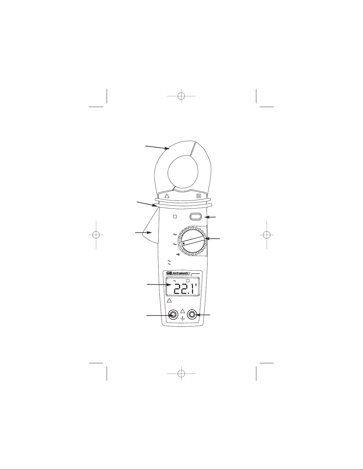
1. Meter Functions
LCD display
Data hold
button
COM input
terminal
Function
select dial
Safety
protection ring
Positive input
terminal
Current
Sensing Clamp
Clamp
opening
handle
GCM-221 11/29/04 10:39 AM Page 3
Page 4
3
2. Specifications
Ranges: Autoranging
AC Voltage: 600 Volts
AC Current: 600 Amps
Resistance (Ohms): 200 Ohms
Accuracy: AC voltage +/- 1.5%
AC current +/- 2.0%
Resistance +/- 1.0%
Function/Range switch: 4 functions
4 positions
Sample Rate: 2 times / sec
Operation Temperature: 32
o
F - 104oF (0oC - 40oC
)
Storage Temperature: 14
o
F - 140oF (-10oC - 60oC
)
31⁄2Digit LCD Display
Recessed Input Jacks: Negative (-) input jack for black test lead, positive
(+) input jack for red test lead.
Batteries: Two - "AAA"
Important:
Read this operators manual thoroughly before using this
meter.This manual is intended to provide basic information
regarding this meter and to describe common test
procedures which can be made with this unit. Many types of
appliance, machinery and other electrical circuit
measurements are not addressed in this manual and should
be handled by experienced service technicians.
Use extreme caution when using this
meter. Improper use of this meter can result in severe
damage to property, severe personal injury or death.
Follow all instructions and suggestions in this operators
manual as well as observing normal electrical safety
precautions. Do not use this meter if you are unfamiliar
with electrical circuits and proper test procedures.
!
WARNING
GCM-221 11/29/04 10:39 AM Page 4
Page 5
4
2.1 For Your Safety
1) Use extreme caution when checking electrical circuits.
2)
Do not stand in wet or damp work areas when
working with electricity.Wear rubber-soled boots or shoes.
3) Do not apply more voltage or current than
the set range of the meter will allow.
4) Do not touch the metal probes of the test
leads when making a measurement.
5) Replace worn test leads. Do not use test leads with
broken or tattered insulation.
6) Discharge a capacitor before measuring it.
7) Remove the test leads from the circuit being measured
as soon as the test is completed.
8) Do not measure voltage when the
function/range switch is set on the resistance (ohms) range.
Never measure current when the meter is set on the
resistance range. Setting the meter on the incorrect function
may burn out some of the internal circuitry and may pose a
safety hazard.
3. Operating Suggestions
1) Set the function/range switch to the proper position before
making a measurement. When the voltage or current is not
known, it MUST be determined that the capacity of the
selected range will handle the amount of voltage or current
in the circuit (see #3 under
For Your Safety
).
2) Avoid placing the meter in areas where vibration, dust or
dirt are present. Do not store the meter in excessively hot,
humid or damp places. This meter is a sensitive measuring
device and should be treated with the same regard as other
electrical and electronic devices.
3) Using the meter in areas with high magnetic fields can
result in inaccurate readings.
4) Never immerse the meter in water or solvents. To clean
the housing use a damp cloth with a minimal amount of
mild soap.
!
WARNING
!
WARNING
!
WARNING
!
WARNING
GCM-221 11/29/04 10:39 AM Page 5
Page 6

3.1 Instrument Familiarization:
Symbol Definition:
3.2
Measuring Resistance:
Switch the function selector to Ω range.
Connect red test lead to "+" terminal and black one to
the "COM" terminal.
Connect tip of the test leads to the points where the
value of the resistance is needed.
Read the result from the LCD panel.
Note: When taking measurements from a circuit,
make sure the power is off and all capacitors
are discharged.
5
GCM-221 11/29/04 10:39 AM Page 6
AC Symbol
Low Battery
Digital Reading
A
VV
Data Hold
H
Continuity
Voltage Indicator
V
Ampere Indicator
A
Ω
Ohm Indicator
!
H
HOLD
OFF
A
V
Ω
A
0 - 400
0 - 600
Ω
0 - 200
Ω
GCM-221
H
600V CAT II
!
300V CAT III
COM
+
!
600V
Page 7
6
!
H
HOLD
OFF
A
V
Ω
A
A
VV
Ω
Ω
0 - 400
0 - 600
0 - 200
H
+
COM
600V CAT II
300V CAT III
!
!
600V
GCM-221
Beeper
!
H
HOLD
OFF
A
V
Ω
A
A
VV
Ω
Ω
0 - 400
0 - 600
0 - 200
H
+
COM
600V CAT II
300V CAT III
!
!
600V
GCM-221
x
x
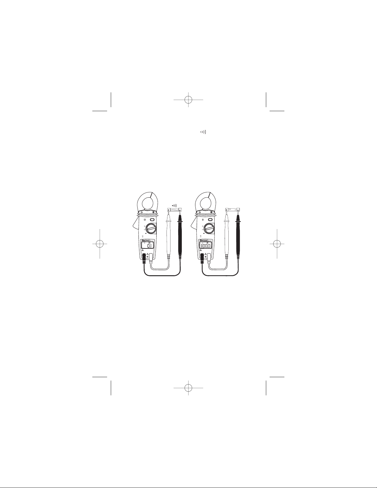
3.3 Testing Continuity:
Switch the function selector to Ω range.
Connect red test lead to "+" terminal and black one to
the "COM" terminal.
Connect tip of the test leads to the points where tests
need to be made.
If the resistance is under 100Ω, the beeper will
sound continuously.
GCM-221 11/29/04 10:39 AM Page 7
Page 8
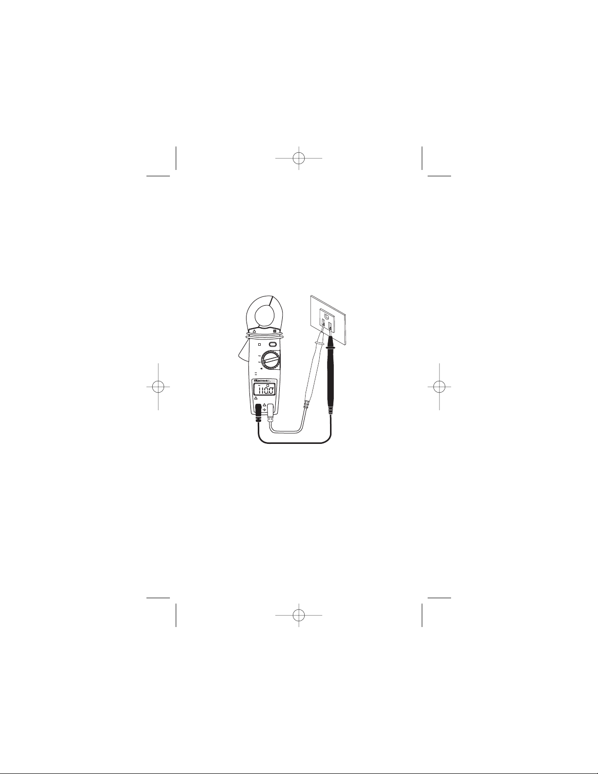
3.4 Measuring AC Volts:
Note: Voltage measurements can only be made using the
test leads and not the clamp-around jaws.
Switch the function selector to V~range.
Connect red test lead to "+" terminal and black one to
the "COM" terminal.
Measure the voltage by touching the test lead tips to
the circuit where the value of voltage is needed.
Read the result from the LCD panel.
7
3.5 Measuring AC AMPS:
Switch the function selector to A~range.
Open the jaws by pressing the handle and insert the
cable to be measured into the jaw.
Close the clamp and note the reading on the LCD.
Note: Never clamp the Jaws around two wires as this
will cause inaccurate readings. Only clamp Jaws
around a single wire — either the HOT or
NEUTRAL WIRE.
Note: When the display is hard to read, push the hold
button to freeze the reading.
GCM-221 11/29/04 10:39 AM Page 8
!
A
VV
Ω
H
HOLD
OFF
A
V
Ω
A
0 - 400
0 - 600
Ω
0 - 200
GCM-221
H
600V CAT II
!
300V CAT III
COM
+
!
600V
Page 9

4.
Changing The Battery:
1. When the battery voltage drops below proper
operating range the symbol will appear on the
LCD display and the battery needs to be changed.
2. Before changing the battery, switch the function
selector to "OFF" and disconnect test leads. Open
the back cover by removing the two screws. Replace
old batteries with two AAA size batteries.
3. Close the back cover and fasten the screws.
!
H
HOLD
OFF
A
V
Ω
A
A
V
V
Ω
Ω
0 - 400
0 - 600
0 - 200
H
+
COM
600V CAT II
300V CAT III
!
!
600V
G
C
M
-22
1
00
CORRECT
✔
!
H
HOLD
OFF
A
V
Ω
A
A
VV
Ω
Ω
0 - 400
0 - 600
0 - 200
H
+
COM
600V CAT II
300V CAT III
!
!
600V
GCM-221
oo
INCORRECT
✗
8
GCM-221 11/29/04 10:39 AM Page 9
Page 10

Contenidos
1. Funciones del Polímetro
2. Especificaciones
2.1 Para Su Seguridad
3. Sugerencias de Funcionamiento
3.1 Medición de la Resistencia
3.2 Medición del Voltaje de CA y CC
3.3 Medición de la Intensidad de CA A
3.4 Medición de Voltaje CA
3.5 Medición de la Intensidad CA
4. Cambio de pilas
11
GCM-221 11/29/04 10:39 AM Page 11
Page 11

!
H
HOLD
OFF
A
V
Ω
A
A
VV
Ω
Ω
0 - 400
0 - 600
0 - 200
H
+
COM
600V CAT II
300V CAT III
!
!
600V
GCM-221
1. Funciones del Polímetro
Dispositivo
visualizador de
pantalla de
cristal líquido
Interruptor
de retención
de datos
Terminal de
alimentación
COM
Dispositivo
de selección
de función
Anillo de
protección de
seguridad
Terminal de
alimentación
positiva
Abrazadera
sensora de
corriente
Manivela
de apertura
de abrazadera
12
GCM-221 11/29/04 10:39 AM Page 12
Page 12

2. Especificaciones
Rangos: Autoreglaje
Voltaje CA: 600 Voltios
Intensidad CA: 600 Amperios
Resistencia (Ohmios): 200 Ohmios
Precisión: CA Voltaje +/- 1.5%
Intensidad CA +/- 2.0%
Resistencia +/- 1.0%
Interruptor Función/Rango 4 funciones
4 posiciones
Frecuencia de muestreo: 2 veces / segundo
Temperatura de manejo: 32oF - 104oF (0oC - 40oC)
Temperatura de almacenamiento: 14oF - 140oF (-10oC - 60oC)
3 1⁄2 Dispositivo visualizador de
pantalla de cristal líquido de dígito
Clavijas de Entrada Demorada: Clavija de entrada negativa (-) para el
conductor de prueba negro, clavija de
entrada positiva (+) para el conductor de
prueba rojo.
Pilas: Dos de tipo "AAA"
Importante:
Lea atentamente este manual del operador antes de utilizar
este polímetro. Este manual está orientado a proporcionar la
información básica referente a este polímetro y a describir
los procedimientos habituales que se pueden realizar con
esta unidad. Muchos tipos de medidas de aplicaciones,
maquinaria y otros componentes eléctricos no están
reseñados en este manual y los deberán realizar técnicos
de servicio experimentados.
Tenga extremo cuidado cuando utilice
este polímetro. El uso inadecuado de este polímetro
puede dar lugar a daños graves al equipo, daños
personales o muerte. Siga todas las instrucciones y
sugerencias de este manual del operador y observe
también las precauciones de seguridad normales para
componentes eléctricos. No utilice este polímetro si no
está familiarizado con los componentes eléctricos y
con los procedimientos de ensayo adecuados.
13
!
ADVERTENCIA
GCM-221 11/29/04 10:39 AM Page 13
Page 13

2.1 Para Su Seguridad
1) Tenga extremo cuidado cuando compruebe
componentes eléctricos.
2)
No se coloque en áreas h medas o mojadas
cuando trabaje con electricidad. Lleve botas o zapatos con
suela de goma.
3) No aplique más voltaje o intensidad de
la que el rango del polímetro permita.
4) No toque las puntas de metal de los
conductores de prueba cuando se realice una medida.
5) Cambie los conductores de prueba desgastados. No use
conductores de prueba con el aislamiento roto o en
mal estado.
6) Antes de medir un condensador, descárguelo.
7) Retire los conductores de prueba del circuito que se está
midiendo tan pronto como se haya concluido la prueba.
8) No mida el voltaje cuando el interruptor
de función/rango esté indicando el rango de resistencia
(ohmios). No mida nunca intensidad cuando el polímetro
esté ajustado para la medida de resistencia. No mida
nunca voltaje de CA cuando el polímetro esté ajustado
para voltaje de CC. Al colocar el polímetro en la función
incorrecta, puede quemar algunos de los circuitos
internos y puede dar lugar a un riesgo de peligro
de seguridad.
3. Sugerencias de Funcionamiento
1) Coloque el interruptor de función/rango en la posición
adecuada antes de realizar una medida. Cuando el
voltaje o la intensidad no se conoce, DEBE determinarse
de modo que la capacidad del rango seleccionado pueda
soportar el voltaje o la intensidad del circuito (vea #3 en
Para Su Seguridad).
2) No poner el polímetro en zonas en las que haya
vibración, polvo o suciedad. No guarde el polímetro en
sitios excesivamente calientes, h medos o mojados. Este
polímetro es un dispositivo de medida sensible y se ha
de tratar con los mismos cuidados que el resto de los
dispositivos electrónicos.
14
!
ADVERTENCIA
!
ADVERTENCIA
!
ADVERTENCIA
!
ADVERTENCIA
GCM-221 11/29/04 10:39 AM Page 14
Page 14

15
3) Si se utiliza el polímetro en zonas con campos
magnéticos fuertes se pueden producir lecturas no
precisas.
4) Nunca sumerja el polímetro en agua o disolventes. Para
limpiar la caja utilice un paño humedecido con una
cantidad mínima de detergente suave.
3.1 Familiarización con los instrumentos
Definición de símbolos:
3.2 Medición de la Resistencia:
Conmute el selector de función a Ω rango.
Conecte el conductor de pruebas rojo a la terminal
positiva y el negro a la terminal "COM".
Conecte los extremos de los conductores de
pruebas a los puntos en los que se necesita el valor
de la resistencia.
Lea los resultados en el panel de la pantalla de
cristal líquido.
Nota: Cuando se tomen mediciones de un circuito,
asegúrese de que la potencia está
desconectada y todos los capacitores
estén descargados.
GCM-221 11/29/04 10:39 AM Page 15
Símbolo de corriente alterna
Batería baja
Lectura digital
H
Retención de datos
Continuidad
Indicador de voltaje
V
Indicador de amperios
A
Ω
Indicador de ohmios
Page 15

16
3.3 Prueba de continuidad:
Conmute el selector de función a Ω rango.
Conecte el conductor de pruebas rojo a la terminal
positiva y el negro a la terminal "COM".
Conecte los extremos de los conductores de pruebas
a los puntos en los que se necesita hacer las pruebas.
Si la resistencia es inferior a 100 Ω, el avisador
sonará continuamente.
!
H
HOLD
OFF
A
V
Ω
A
A
VV
Ω
Ω
0 - 400
0 - 600
0 - 200
H
+
COM
600V CAT II
300V CAT III
!
!
600V
GCM-221
Zumbador
!
H
HOLD
OFF
A
V
Ω
A
A
VV
Ω
Ω
0 - 400
0 - 600
0 - 200
H
+
COM
600V CAT II
300V CAT III
!
!
600V
GCM-221
x
x
GCM-221 11/29/04 10:39 AM Page 16
!
H
HOLD
OFF
A
V
Ω
A
A
0 - 400
VV
0 - 600
Ω
0 - 200
Ω
GCM-221
H
600V CAT II
!
300V CAT III
COM
+
!
600V
Page 16

17
3.4
Medición de Voltaje CA:
Nota: La medición de voltaje sólo se puede realizar
utilizando las puntas de prueba, no con las pinzas
abrazadera.
Conmutar el selector de función a rango V~.
Conecte el conductor de pruebas rojo a la terminal positiva
y el negro a la terminal "COM".
Mida el voltaje tocando los extremos de los conductores
de pruebas al circuito en el que se necesita el valor del
voltaje.Lea los resultados en el panel de la pantalla de
cristal líquido.
3.5 Medición de la Intensidad CA:
Conmute el selector de función a rango A~.
Abra las mordazas presionando la manivela e
introducir el cable que desea medir en la mordaza.
Cierre la abrazadera y anote la lectura de la pantalla
de cristal líquido.
Nota: Nunca fije las mordazas en torno a dos cables
ya que esto causaría lecturas inexactas. Fije
solamente mordazas en torno a un único
cable - bien sea el CABLE CON CORRIENTE
o el NEUTRO.
Nota: Cuando el dispositivo visualizador sea de difícil
lectura, presione el botón de parada para
congelar la lectura.
GCM-221 11/29/04 10:39 AM Page 17
A
VV
!
H
HOLD
OFF
A
V
Ω
A
0 - 400
0 - 600
Ω
0 - 200
Ω
GCM-221
H
600V CAT II
!
300V CAT III
COM
+
!
600V
Page 17

18
!
H
HOLD
OFF
A
V
Ω
A
A
V
V
Ω
Ω
0 - 400
0 - 600
0 - 200
H
+
COM
600V CAT II
300V CAT III
!
!
600V
G
C
M
-221
00
CORRECTO
✔
!
H
HOLD
OFF
A
V
Ω
A
A
VV
Ω
Ω
0 - 400
0 - 600
0 - 200
H
+
COM
600V CAT II
300V CAT III
!
!
600V
GCM-221
oo
INCORRECTO
✗
4. Cambio de pilas:
1. Cuando el voltaje de las pilas caiga por debajo del
rango de funcionamiento adecuado el símbolo
aparecerá en el dispositivo visualizador de la
pantalla de cristal líquido y será necesario cambiar
2. Antes de cambiar las pilas, conmute el selector de
función a la posición "OFF" y desconecte los
conductores de pruebas. Abra la tapa trasera
retirando los dos tornillos. Sustituya las pilas viejas
3. Cierre la tapa trasera y apriete los tornillos.
GCM-221 11/29/04 10:39 AM Page 18
Page 18

Table des matières
1. Fonctions du multimètre
2. Caractéristiques
2.1 Consignes De Sécurité
3. Suggestions d'Utilisation
3.1 Mesurer une Résistance
3.2 Mesurer les Volts Alternatifs et Continus
3.3 Mesurer les Ampères Alternatifs
3.4 Mesure des tensions alternatives
3.5 Mesure du courant alternatif (A)
4. Remplacement des piles
20
GCM-221 11/29/04 10:39 AM Page 20
Page 19

!
H
HOLD
OFF
A
V
Ω
A
A
VV
Ω
Ω
0 - 400
0 - 600
0 - 200
H
+
COM
600V CAT II
300V CAT III
!
!
600V
GCM-221
1. Fonctions de l'appareil de mesures
Afficheur à
cristaux
liquides
Bouton de
stockage des
données
Borne d'entr’ee
COM
Cadran du
sélecteur
de fonction
Anneau de
protection
Borne d'entrée
du Positif
Pince
ampèremétrique
Poignée
d'ouverture
de la pince
21
GCM-221 11/29/04 10:39 AM Page 21
Page 20

2. Caractéristiques
Gammes: Commutation automatique des gammes
Tension en CA: 600 Volts (V)
Courant en CA: 600 Ampères (A)
Résistance (Ohms): 200 Ohms
Précision: Tension en CA +/- 1,5%
Courant en CA +/- 2,0%
Résistance +/- 1,0%
Commutateur Fonction/Gamme: 4 fonctions
4 positions
Fréquence d'échantillonnage: 2 fois/s
Tempéerature de fonctionnement: 32oF – 104oF (0oC – 40oC)
Temp’erature de stockage: 14oF – 140oF (-10oC – 60oC)
3 1⁄2 Afficheur numérique à
cristaux liquides
Jacks d'entrée encastrés: Jack d'entrée négatif(-) pour le cordon de
tests noir, jack d'entrée positif (+) pour le
cordon de tests rouge.
Piles: Deux - "AAA"
Important:
Lisez le manuel d'utilisation entièrement avant d'utiliser le
multimètre. Ce manuel a pour objectif de vous aider à
utiliser le mètre et contient les procédures générales des
tests pouvant être réalisés avec cet appareil. Il existe de
nombreux types de mesures d'appareils, de machines et
autres circuits électriques auxquels ce manuel ne fait pas
référence et qui devront donc être effectuées par des
techniciens expérimentés.
L'utilisation de ce multimètre nécessite
l'emploi de nombreuses précautions. Une mauvaise
utilisation du multimètre peut entraîner des dommages
matériels importants, de graves préjudices corporels
ou la mort. Suivez toutes les instructions et suggestions
contenues dans ce manuel d'utilisation et respectez
les mesures de sécurité électrique habituelles. N'utilisez
pas ce multimètre si vous n'êtes pas familiarisé
avec les circuits électriques et les procédures de
tests appropriées.
22
!
AVERTISSEMENT
GCM-221 11/29/04 10:39 AM Page 22
Page 21

!
AVERTISSEMENT
!
AVERTISSEMENT
!
AVERTISSEMENT
!
AVERTISSEMENT
2.1 Consignes De Sécurité
1) Soyez extrêmement prudent lorsque vous contrôlez les
circuits électriques.
2)
Vous ne devez pas vous trouver dans un
espace de travail mouillé ou humide lorsque vous travaillez
avec l'électricité. Portez des bottes ou des chaussures avec
des semelles en caoutchouc.
3) N'appliquez pas de tensions ou de
courants supérieurs à ceux de la gamme prévue sur
le multimètre.
4) Ne touchez pas les sondes
métalliques des connexions d'essai lorsque vous r
éalisez une mesure.
5) Remplacez les connexions d'essai usées. N'utilisez
pas de connexions d'essai avec une isolation cassée
ou défectueuse.
6) Un condensateur doit être déchargé avant d'être mesuré.
7) Retirez les connexions d'essai du circuit mesuré dès que
le test est terminé.
8) Ne mesurez pas la tension lorsque le
sélecteur de fonctions/gammes est réglé sur la gamme
résistance (ohms). Ne mesurez jamais le courant lorsque
le multimètre est réglé sur la gamme résistance. Ne
mesurez jamais la tension alternative lorsque le
multimètre est réglé sur tension continue. Le fait de régler
le multimètre sur la mauvaise fonction risque de griller
certains des circuits internes et peut être dangereux.
3. Suggestions d'Utilisation
1) Réglez le sélecteur de fonctions/gammes sur la position
appropriée avant d'effectuer une mesure. Lorsque la
tension ou le courant n'est pas connu, vous DEVEZ vous
assurer que la capacité de la gamme sélectionnée est
suffisante pour la quantité de tension ou de courant dans
le circuit (voir #3 Consignes de Sécurité ci-dessous).
23
GCM-221 11/29/04 10:39 AM Page 23
Page 22

2) Evitez de placer le multimètre dans des lieux avec des
vibrations, de la poussière ou de la saleté. Ne rangez pas
le multimètre dans des endroits où la chaleur ou
l'humidité est excessive. Ce multimètre est un appareil de
mesure fragile et doit être traité avec le même égard que
les autres appareils électriques et électroniques.
3) Si vous utilisez le multimètre dans des lieux avec des
champs magnétiques intenses, les lectures risquent
d'être inexactes.
4) Ne plongez jamais le multimètre dans de l'eau ou des
dissolvants. Pour nettoyer le boîtier, utilisez un chiffon
humide avec juste un peu de savon doux.
3.1 Comment se familiariser avec l'instrument:
Définition des symboles:
3.2
Mesure de la résistance:
Basculer le sélecteur de fonction sur Ω gamme.
Connecter le cordon de tests rouge sur la borne "+"
et le cordon noir sur la borne "COM".
Connecter l'extrémité des cordons de tests sur les
points dont il est nécessaire de connaître la valeur
de la résistance.
Lire les résultats sur le panneau à cristaux liquides.
Remarque: Au cours de la prise de mesures sur un
circuit, s'assurer que l'alimentation est
hors service et que les capacités
sont déchargées.
24
GCM-221 11/29/04 10:39 AM Page 24
Symbole Courant Alternatif
Pile déchargée
Lecture numérique
Stockage des données
H
V
A
Ω
Continuité
Voyant de tension
Voyant de courant
Voyant de
résistance (Ohm)
Page 23

25
3.3 Test de la continuité:
Basculer le sélecteur de fonction sur Ω gamme.
Connecter le cordon de tests rouge sur la borne "+"
et le cordon noir sur la borne "COM".
Connecter l'extrémité des cordons de tests sur les
points devant être testés.
Si la résistance est inférieure à 100 Ω, l'avertisseur
sonore résonnera sans arrêt.
GCM-221 11/29/04 10:39 AM Page 25
!
H
HOLD
OFF
A
V
Ω
A
A
0 - 400
VV
0 - 600
Ω
0 - 200
Ω
GCM-221
H
600V CAT II
!
300V CAT III
COM
+
!
600V
A
VV
Avertisseur
sonore
x
x
A
VV
!
H
HOLD
OFF
A
V
Ω
A
0 - 400
0 - 600
Ω
0 - 200
Ω
GCM-221
H
600V CAT II
!
300V CAT III
COM
+
!
600V
!
H
HOLD
OFF
A
V
Ω
A
0 - 400
0 - 600
Ω
0 - 200
Ω
GCM-221
H
600V CAT II
!
300V CAT III
COM
+
!
600V
Page 24

26
3
.4 Mesure des tensions alternatives:
Remarque: La mesure de tension peut uniquement être
réalisée en utilisant les cordons de mesures
et en aucun cas la pince ampèremétrique.
Commuter le sélecteur de fonctions sur la gamme V~.
Connecter le cordon de tests rouge sur la borne "+" et
le cordon noir sur la borne "COM".
Effectuer la mesure de la tension en touchant le circuit
dont la mesure de tension est nécessaire avec
l'extrémité des cordons de tests.
Lire les résultats sur le panneau à cristaux liquides.
3.5 Mesure du courant alternatif (A):
Commuter le sélecteur de fonction sur la gamme A~.
Ouvrir la pince en appuyant sur la poignée et insérer le
câble devant être mesuré entre les mâchoires.
Refermer la pince et prendre note de la lecture sur
l'afficheur à cristaux liquides (LCD).
Remarque: Ne jamais refermer les mâchoires de la pince
autour de deux câbles, sous peine d'obtenir
des mesures imprécises. Refermer
uniquement les mâchoires autour d'un seul
câble - soit le POSITIF, soit le NEUTRE.
Remarque: Quand l'afficheur est difficile à lire, appuyer
sur le bouton de stockage des données pour
figer la lecture de la mesure.
GCM-221 11/29/04 10:39 AM Page 26
!
A
VV
Ω
H
HOLD
OFF
A
V
Ω
A
0 - 400
0 - 600
Ω
0 - 200
GCM-221
H
600V CAT II
!
300V CAT III
COM
+
!
600V
Page 25

4.
Remplacement des piles:
1. Quand la tension de la pile descend en dessous de
la valeur correcte de fonctionnement, le
symbole apparaît sur l'afficheur à cristaux liquides et
la pile doit être remplacée.
2. Avant de remplacer la pile, commuter le sélecteur de
fonction sur "OFF" (ARRÊT) et déconnecter les
cordons de tests. Ouvrir le couvercle arrière en
déposant les deux vis. Remplacer les anciennes
piles par deux piles neuves AAA.
3. Fermer le couvercle arrière et visser les vis.
!
H
HOLD
OFF
A
V
Ω
A
A
V
V
Ω
Ω
0 - 400
0 - 600
0 - 200
H
+
COM
600V CAT II
300V CAT III
!
!
600V
G
C
M
-2
21
00
CORRECT
✔
!
H
HOLD
OFF
A
V
Ω
A
A
VV
Ω
Ω
0 - 400
0 - 600
0 - 200
H
+
COM
600V CAT II
300V CAT III
!
!
600V
GCM-221
oo
INCORRECT
✗
27
GCM-221 11/29/04 10:39 AM Page 27
Page 26

ZX00023 • ©2000 GB Gardner Bender
6615 Ordan Drive, Units 14-15 • Mississauga, Ontario • L5T 1X2 Canada
In Toronto Call 905-564-5749 • Toll Free 1-800-268-4987 • Fax 1-800-461-2456
6101 N. Baker Road • Milwaukee, WI 53209 • 414-352-4160 • Fax 414-352-2377
www.gardnerbender.com
GCM-221 11/29/04 10:39 AM Page 28
Gardner
Bender
 Loading...