

Page 1
IMPORTANT: RECEIVING INSTRUCTIONS: Visually inspect
all components for shipping damage. If any shipping damage is
found, notify carrier at once.
Shipping damage is NOT covered by warranty. The carrier is
responsible for all repair or replacement costs resulting from
damage in shipment.
Instruction
Sheet
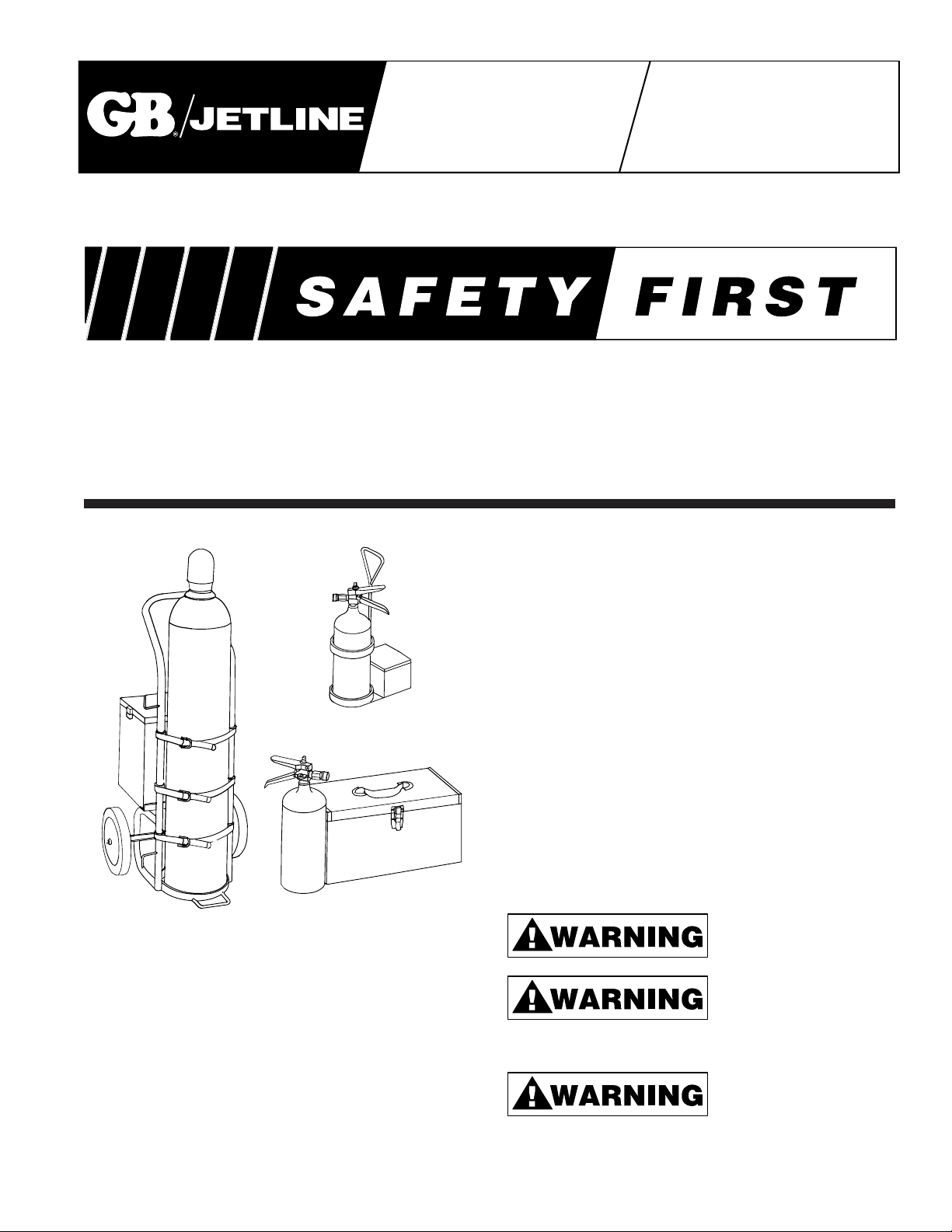
CO2 CONDUIT
FISHING
SYSTEMS
IMPORTANT—USER SAFETY AND PROTECTION: In setting up systems to fit your operations, care must be taken to select the
proper components and design to insure appropriate integration with your operations and existing equipment and that all safety
measures have been taken to avoid the risk of personal injury and property damage from your application or system.
GB ELECTRICAL CANNOT BE RESPONSIBLE FOR DAMAGE OR INJURY CAUSED BY UNSAFE USE, MAINTENANCE OR
APPLICATION OF ITS PRODUCTS. Please contact GB ELECTRICAL for guidance when you are in doubt as to the proper safety
precautions to be taken in designing and setting up your particular application. To protect your warranty use only GB/Enerpac
hydraulic oil.
Model JO25C Power Pak II™ (5 lb. CO
2
System with Caddy)
Model JO25 Power Pak I™
Model JO250 Powr House™ (5 lb. CO
2
System)
(50 lb. CO
2
System)
Model JO220 Powr House™ (20 lb. CO2System) not shown.
INTRODUCTION
The GB/Jet Line Carbon Dioxide (CO
2
) Conduit Fishing Systems are high pressure tools which are used to place a pull line
in most conduit runs from
1
/2” through 6” diameter.
These systems are completely self-contained and no other
energy source is required. They are convenient to use in
remote locations and in new construction where there is no
temporary electrical power available or where only one or two
conduit runs are required.
Each system consists of five basic components:
• A high pressure gas (CO
2
) driving media.
• A control valve to start and stop the gas flow.
• Hose and seal-off to conduct the gas to the conduit and form
a seal at the conduit entrance.
• A line carrier to serve as a movable piston that supplies the
pulling force.
• Pull line for pulling wire through the conduit or to pull in a
rope or cable for large difficult runs.
A thorough understanding of all components and their function
and operating precautions is essential for safe and efficient use
of the system.
Read all of the instructions before attempting to use the system
or blow line in the Conduit.
IMPORTANT SAFETY INSTRUCTIONS
Wear a hard hat, eye
protection, and gloves.
When using a carbon dioxide
conduit fishing system basic
precautions should always
be followed. FAILURE TO OBSERVE THESE INSTRUCTIONS COULD RESULT IN SERIOUS INJURY OR DEATH.
Do not discharge a cylinder
containing carbon dioxide
(CO
2
) in a non-ventilated
manhole or other non-ventilated areas. Carbon dioxide is relatively inert, but is heavier than air and will displace it and accumulate in depressions and along the floor. Concentrations of
Page 2
10% (100,000 ppm) can produce unconsciousness and death
from oxygen deficiency. Concentrations of 5% may produce
shortness of breath and headaches. Provide adequate
ventilation.
When operating a CO
2
System,
do not direct the high pressure
CO
2
stream towards any part of
the body; serious injury or possible death could occur.
All GB/Jet Line Systems are
designed to force loose debris
of all types out of the conduit by
means of a pressurized force. Serious or critical injury could
occur to anyone struck by high velocity exiting debris or the line
carrier. Warn all personnel to stand clear of the conduit exit prior
to commencing pressurization, flush-out procedures, or blowing
line into the conduit.
Do not hold the seal-off by therubber cone when discharging
CO
2
. Maintain a firm grip on
the seal-off hose and operating valve at all times while discharging CO
2
. The high velocity jet of CO2causes a recoil force, and
the free end of the hose could whip around possibly causing
injury or damage to equipment.
During use, portions of the
cylinder, valve, hose and seal-
off will become very cold as
may be noted by frost forming on these parts. Do not touch these
areas with bare hands. If bare hands become frozen to the frosted parts, do not pull away–run water over hand and metal part to
free it.
When transporting a GB/Jet
Line 5 Ib. CO
2
System, remove
the seal-off and hose assembly, install the safety pin in the valve handle, and screw down the
handle regulating screw to hold the safety pin in place.
Always make sure the 20 Ib.
and 50 Ib. CO
2
cylinders are
securely strapped to the cart to
prevent overturning and damage to the cylinder and valve.
When not in use or while being transported, close the cylinder
valve on 20 Ib. and 50 Ib. cylinders, depressurize operating hose
assembly and remove it from the cylinder to prevent accidental
discharge. Replace the screw on valve cover on 50 Ib. cylinders.
With excessive or constant use,
the liquid CO
2
in the cylinder
may freeze solid into dry ice,
the pressure in the cylinder may drop to zero, and the gas may
not flow. If this occurs, allow the cylinder to thaw out at room temperature; the pressure will return to normal. Do not apply heat to
the cylinder to speed up thawing. This could raise the cylinder
pressure to an excessively high level, causing the cylinder valve
safety disc to rupture and discharge the cylinder contents.
If the safety disc ruptures, have it replaced at an authorized fire
extinguisher service center, or replace it with a single GB/Jet Line
safety disc.
IMPORTANT: Use commercial grade CO
2
only when refilling the
CO
2
cylinder. Never, under any circumstances, substitute any
gas other than carbon dioxide (CO
2
). The cylinder is pressure
rated for CO
2
only.
Use only a GB/Jet Line System. GB has incorporated safety features into the CO
2
system; orifice flow restrictions, adjustable flow
regulation, low temperature pressure rated hose, and a rupture
disc pressure relief system.
Do not substitute any parts or accessories not manufactured by
GB/Jet Line on your CO
2
system.
Have the cylinders hydrostatically pressure tested by a qualified
local fire extinguisher service center at two year intervals. Under
no circumstances should the hydrostatic test intervals exceed
five years.
Observe all federal, state and local codes concerning handling,
transporting and storing of compressed gas cylinders.
CARBON DIOXIDE (CO2)
Carbon dioxide may exist in three physical states; solid (dry ice at
-109° F), liquid (under pressure) or gaseous CO
2
. Only the liquid
and gaseous states are useful in conduit fishing.
Carbon dioxide is normally stored in cylinders in liquid form under
pressure (838 P.S.I. at 70°F). It will rapidly turn into a high pressure, high velocity gas when the cylinder or operating hose valve
is opened. It is this high pressure, high velocity gas that is used
to drive the line carrier through the conduit. During the expansion
process, portions of the cylinder, valve, hose, and seal-off will
become very cold as may be visibly noted by frost forming on
these components.
Wear gloves, do not touch
these areas with bare hands.
Bare hands may become
frozen to the metal parts.
GB/JET LINE CO2 CYLINDERS
GB/Jet Line supplies three sizes of CO
2
Cylinders, 5, 20, and 50
Ibs., meeting U.S. Department of Transportation (DOT) requirements for compressed gas. Each cylinder bears a neck stamp
showing a DOT number indicating the maximum allowable working pressure, serial number, manufacturers identification code,
and date of manufacture.
The 5, 20, and 50 Ib. sizes indicate the weight in pounds of liquid
CO
2
that the cylinder will hold. CO2cylinders are supplied filled
and ready for use. When a cylinder becomes empty, it may be
refilled by most authorized fire extinguisher service centers. The
5 Ib. CO
2
cylinders may be refilled from the 50 Ib. CO2cylinder.
A refill connector Model RV5 is required for this operation. See
the refilling instructions on page 6.
Do not refill the CO
2
cylinders
with air, nitrogen or other
gasses. The cylinder is pressure rated for CO
2
use only.
Hydrostatic Pressure Testing –CO2cylinders returned to GB/
Jet Line for service or repair will be hydrostatically pressure tested for safety if the latest date stamp is more than two years old.
When a cylinder passes the hydrostatic pressure test, the month
and year shall be stamped on the cylinder by the approved testing center. Cylinders failing the pressure test must be destroyed.
2
Page 3
CO2 Cylinder Specifications
Model No. 1103N 1208 950
Cyl. Size 5 Ib. 20 Ib. 50 Ib.
Weight (full) * 14 Ibs. 55 Ibs. 154 Ibs.
Weight (empty) * 9 Ibs. 35 Ibs. 104 Ibs.
Weight (CO
2
) 5 Ibs. 20 Ibs. 50 Ibs.
Diameter * 5” 8” 9”
Height* 17
1
/2” 27” 51”
Valve Type Squeeze Rotary Rotary
Valve Coupling Ball Lock Threaded Threaded
Pressure (70°F) 838 P.S.I. 838 P.S.I. 838 P.S.I.
Maximum Cylinder See DOT 3 AA rating
Working Pressure stamped on cylinder neck
* Dimensions and empty weight of the cylinder may vary slightly,
depending on cylinder manufacturer.
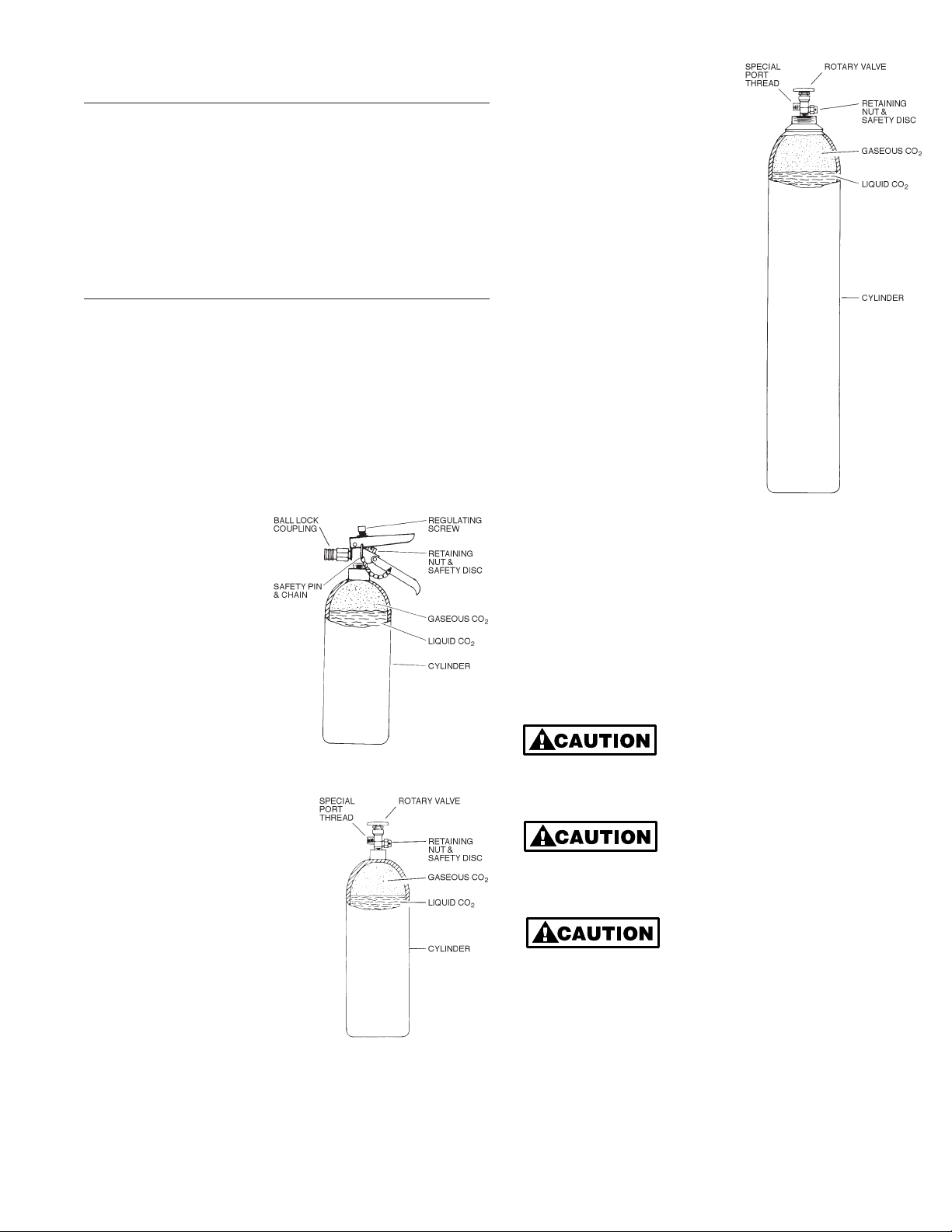
Model 1103N 5 Ib. CO2 Cylinder – The 1103N, 5 Ib. CO
2
cylinder, is used in both Power Pak I and Power Pak ll conduit fishing
kits.
The cylinder is equipped with a "squeeze to operate" hand valve.
A thumb screw is used to limit the operating handle movement
and regulate the amount of CO
2
dispensed. Adjusting the screw
will permit a mere trickle of CO
2
and backing out further will permit full handle travel and
a full flow of CO
2
(Refer
to Figure 1).
A safety pin inserted
through the handle and
valve body prevents the
handle from being
depressed accidentally. The
pin should always
be in place when the cylinder is not in use or when
the cylinder is being
transported.
A ball lock quick coupling is
provided for attaching sealoff Model 1215 or 1216.
Model 1208 20 Ib. CO2 Cylinder –
The model 1208, 20 Ib. cylinder, is
a cart-transported cylinder weighing approximately 55 Ibs. when
fully charged with 20 Ibs. of CO
2
.
This cylinder should always remain
strapped in the cart to prevent
overturning and damage to the
cylinder or valve.
The cylinder has a rotary hand
valve with a special port thread.
The valve requires a matching coupling nut and stem with an O-ring
face seal as supplied on Model
1105 CO
2
Operating Valve and
Hose Assembly (Refer to Figure 2
and 9).
Model 950 50 Ib. CO2 Cylinder– The model 950, 50 Ib. CO
2
cylinder, is a cart transported
cylinder weighing approximately
154 Ibs. when fully charged with
50 Ibs. of liquid CO
2
(Refer to
Figures 3 and 9).
The cylinder is equipped with a
rotary hand valve with a special
port thread. The valve requires
a matching coupling nut and
stem with an O-ring face seal
as supplied on the Model 1105
CO
2
Operating Valve and Hose
Assembly.
A screw on valve safety cover is
supplied with the cylinder and
should always be in place when
the cylinder is not in use or while
the cylinder is being transported.
The 50 Ib. cylinder may be used
as a field refilling supply tank for
the 5 Ib. cylinder if desired. See
refilling instructions on page 6.
USE AND OPERATION
With the GB/Jet Line CO
2
system, gas generated from the liquid
CO
2
stored in the cylinder is used to propel the line carrier
and pull line through the conduit.
When using the CO
2
system, adjust the flow regulating screw on
the “squeeze to operate” valve handle on the 5 Ib. cylinder or on
the 1105 valve and hose assembly. Regulate the flow to a moderate amount sufficient to keep the line carrier moving and the
line flowing into the conduit. Develop a light touch and conserve
CO
2
(Refer to Figure 4).
The valve handle is very easy to
operate when the regulating
screw is backed out. Do not
attempt to force the handle or damage to the screw and handle
could occur.
There is substantial force when
the valve is operated and CO
2
is
discharged in open air. Point the
nozzle in a safe direction and maintain a firm grip on the seal-off
frost guard and valve.
Where conduit is run under
ground; it may contain water or
be subjected to flooding. It may
be desirable to blow the water out before blowing a line in the
conduit. Because the water will be blown out ahead of the line
carrier, take precautions to protect nearby equipment that could
be damaged by moisture and sludge (Refer to Figure 16).
3
Figure 1
1103N 5 Lb. CO
2
Cylinder
Figure 2
1208 20 Lb. CO
2
Cylinder
Figure 3
950 50 Lb. CO
2
Cylinder
Page 4

BLOWING LINE IN THE CONDUIT
The GB/Jet Line CO2system is designed to blow a line in
“sealed” conduit such as EMT with compression type couplings,
rigid conduit, and plastic conduit with adhesive bonded joints.
These types of conduit generally require very little effort to install
a pull line with the CO
2
system.
There are some conduit runs that will be difficult or impossible to
blow a line in with the CO
2
system, such as:
• Conduit containing hard packed sand, silt, debris, or concrete.
• Conduit with separated joints.
• Conduit with two sizes of duct connected by a reducer coupling.
• Conduit with unsealed set screw couplings.
• Small diameter conduit of several hundred feet with multiple
bends.
PREPARATION
It is helpful to know the purpose for which a line is to be used
once it has been blown into the conduit. This will aid the user in
selecting the appropriate line for the job.
Knowing the approximate length of the conduit will prevent
selecting a line that is too short for the run; i.e., if the user wishes
to place a light line in a
3
/4” conduit with an estimated length of
195 to 200 feet, a 300 ft. power saver line package should be
selected for the run. An alternate solution would be to use a
3
/4”
foam line carrier pulling bulk nylon line. Either selection would
insure an adequate length of line.
Selecting the Pull Line – The following list is presented as a
guide in selecting a pull line. Users must determine for themselves which best fits their needs.
1. Identification of a conduit run termination where multiple con-
duit runs originate at a single location.
Recommended Line: Power Saver Line Packages or Bulk
Nylon Line.
2. Placing a line in the conduit for use at a later date.
Recommended Line: Small conduit
1
/2”, 3/4”, and 1” Power
Saver Line Packages, Bulk Nylon Line or PL232. Larger conduit 1
1
/4” through 6” Tag-Along Line Packages, PL Series
Line PL232, PL235, and PL2310.
3. Pulling in a larger line, rope or steel winch cable.
Recommended Line: Small conduit
1
/2”, 3/4” and 1”. Same as
2 above. Larger conduit PL232 or PL235.
4. Pulling wire in conduit.
Recommended Line: PL232, PL235, and PL2310.
SEAL-OFFS
Seal-offs provide a means of making the final connection
between the CO
2
operating valve and the conduit, as well as providing a means of feeding pull line into the conduit. The tapered
rubber cone that forms the seal at the conduit entrance must be
held firmly in the conduit when flushing out water and debris or
blowing line in the conduit. Be sure to keep a firm hold on the
seal-off hose frost guard while operating unit.
All CO
2
seal-offs are equipped with a male quick disconnect plug
that plugs into the operating valve ball lock coupling on the 5 Ib.
CO
2
cylinder valve or the 1105 operating valve and hose assem-
bly used with the 20 Ib. and 50 Ib. CO
2
cylinders (Refer to
Figure 4).
Connect the seal-off to the 5 Ib. CO
2
cylinder valve or the 1105
operating valve as follows:
1. Rotate the valve ball
lock coupling sleeve
to align notch with
embedded ball
(Refer to Figure 4).
2. Retract the ball lock
sleeve.
3. Plug in seal-off connector.
4. Release the sleeve to lock coupling.
5. Rotate sleeve notch away from embedded ball to prevent acci-
dental disconnection.
Disconnect the seal-off from the CO
2
operating valve when
threading pull line through the feed port and attaching a line carrier. This step will make the preparation job easier and eliminate
the possibility of accidental discharge of CO
2
.
Always maintain a firm grip on
the seal-off hose frost guard
when the seal-off is connected
to the operating valve (See Figure 5). This will prevent the free
end from whipping around while discharging CO
2
.
Model 1215 Seal-Off – The 1215 Seal-Off with two foot hose is
designed for use with the 5 Ib. CO
2
cylinder for blowing line in
3
/4”, 1/2”, 1”, and 11/4” conduit. This seal-off is required for blowing
power saver line packages in
1
/2”, 3/4”, and 1” conduit. The 1215
seal-off works equally well with the larger GB/Jet Line 20 and 50
Ib. systems when connected to the 1105 CO
2
operating valve
and hose assembly.
The feed through port will accept bulk nylon line and pull line up
to
1
/8” diameter.
Model 1216 Seal-Off – The 1216 Seal-Off with two foot hose is
similar to the 1215 except for a larger sealing cone. It may be
used in conduit sizes 1
1
/2” through 2 1/2” diameter and with pull
line up to
1
/8” diameter.
Model 1206 Seal-Off – The 1206 Seal-Off is designed for use
with the larger GB/Jet Line 20 and 50 Ib. CO
2
systems. It must be
used with the 1105 operating valve and hose assembly. The
large rubber cone will fit conduit sizes 1
1
/2” through 6”. The feed
through port will accept all GB/Jet Line PL Series pull lines
PL232, PL235, and PL2310.
OPERATING ACCESSORIES
GB/Jet Line provides specially designed easy-to-use operating
accessories for the CO
2
systems that meet most conduit fishing
needs.
Model 1105 Operating Valve and Hose Assembly – The 1105
operating valve and 12 ft. hose assembly connects to the 20 or
50 Ib. CO
2
cylinder and allows the operator a wide range of
movement to reach hard-to-get-to conduit runs.
4
RETAINING NUT
& SAFETY DISC
OPERATING
HANDLE
REGULATING SCREW
BALL LOCK
COUPLING
SEAL-OFF FITTING
MALE PLUG
SLEEVE NOTCH &
EMBEDDED BALL
CARRY HANDLE
Figure 4
Operating Valve and Seal-Off Coupling
Page 5

Connection to the 20 Ib. or 50 Ib. CO2cylinder rotary valve is
made with the special thread coupling nut and O-ring face seal
on the hose stem. The coupling nut screwed hand tight on the
valve port is all that is required for a good seal. When the cylinder
rotary valve is opened (opening one or two turns is sufficient) the
hose is pressurized up to the operator held hand valve.
Any of the GB/Jet Line CO
2
seal-offs may be threaded up with
pull line and line carrier and then connected to the operating
valve quick coupling. An adjusting screw is provided on the operating valve handle to limit the valve travel and regulate the flow of
CO
2
gas as required by the user.
When not in use, disconnect the seal-off from the operating
valve, close the cylinder rotary valve, operate the operating valve
to depressurize the hose and remove it from the cylinder valve.
Store the hose on the cylinder cart hose hanger hooks or in the
cart tool box.
Model 1142 Angle Adapter (See Figure 11) – The 1142 Angle
Adapter is provided for use with the 1215 seal-off for installing
line in small junction boxes and hard-to-get-to conduit.
To use, remove the rubber cone on the 1215 seal-off and screw
the angle adapter on the threaded end of the brass feed through
fitting.
Always maintain a firm grip on the seal-off hose behind the feed
through fitting to counteract the recoil force of the high velocity
CO
2
gas.
Blowing Line Packages through
Conduit – This is the easiest
method of placing a light weight pull
line in the conduit. The line package
or seal-off requires no thread up for
this operation. However, it is recommended that the seal-off be connected to the operating valve and a preliminary CO
2
flow adjustment be
made by alternately operating the
valve and adjusting the regulating
screw. If more CO
2
flow is required,
back out the regulating screw one
or two more turns (Refer to Figure 4
and 5).
Always maintain a firm grip on the
frost guard of the seal-off hose to
prevent it from whipping around.
Power Saver Line Package –
Select the Power Saver line package for size and length of line to fit
up to 1” diameter conduit. It is
recommended that you flex the
package back and forth two or
three times to loosen it prior to its
use. This will make the line easier to dispense.
Proceed as follows:
1. Pull out approximately two
feet of line. Hold on to this trailing end to prevent its loss in the
conduit.
2. Insert the line package in the conduit-foam tip first.
3. Hold the seal-off hose frost
guard, force rubber cone firmly in
the conduit entrance and give the
line package two or three quick
spurts of CO
2
. The package
should be blown through the conduit trailing a line as it goes
(Refer to Figure 6 and Table 1).
4. It is recommended that
the ends of the line be
tied off until ready for use
to prevent the end from
being accidentally pulled
back into the conduit.
Tag-Along Line Package -
Tag-Along Line Packages
perform the same function
as Power Saver line packages except they are used
in 1
1
/4” diameter and larger
conduit. Tag-Along packages must be used with a
line carrier to supply the
pulling force.
Select the Tag-Along Line
Package and a line carrier
either foam or inflatable that fits the conduit diameter and proceed as follows:
1. If a foam line carrier is selected, attach the Tag-Along pack-
age plastic eye to the foam line carrier hook. Pull out approximately two feet of line and hold on to the trailing end (Refer to
Figure 7).
2. Insert the foam line carrier and Tag-Along package in the
conduit.
3. Hold the seal-off hose frost guard, force rubber cone firmly in
the conduit entrance and squeeze the CO
2
operating valve
handle. Continue to apply a flow of CO
2
until line carrier
comes out the other end of the conduit. The run time will be
longer than for the Power Saver line package because of the
larger conduit and greater volume of CO
2
required. However,
the run time in 3” and 4” conduit 200 and 300 feet long should
be completed in a matter of seconds (Refer to Figure 7).
4. Tie off the ends of the
line to prevent it from
being accidentally
pulled into the conduit.
Inflatable Line Carrier
1. Select an Inflatable line
carrier within its conduit
diameter range and
attach the Tag-Along
Line Package to the
wire bail. Pull out
approximately two feet
of line and hold on to
the trailing end.
5
Figure 6
Blowing a Power Saver Line
Package In Conduit
Conduit Length
Model Dia. Ft.
LP2150
1
/2” 150’
LP3200
3
/4” 200’
LP3300
3
/4” 300’
LP3450
3
/4” 450’
LP4200 1” 200’
LP4300 1” 300’
LP4450 1” 450’
Table 1
Power Saver Line Packages
CONDUIT
1215
SEAL-OFF
POWER SAVER
LINE PACKAGE
TRAILING END
OF LINE
Figure 7
Blowing a Foam Line Carrier and
Tag-Along in Conduit
FOAM
LINE
CARRIER
1216
SEAL-OFF
TRAILING
END OF LINE
CONDUIT
Length Strength
Model Ft. Lbs.
LP2206T 400 22
LP2208T 600 22
LP2207T 800 22
LP1704T 1200 22
LP1705T 600 50
Table 2
Tag-Along Line Packages
Figure 8
Blowing an Inflatable Line Carrier and
Tag-Along in Conduit
THE
INFLATABLE®
LINE CARRIER
1216 SEAL-OFF
CONDUIT
TAG-A-LONG
LINE PACKAGE
TRAILING
END OF LINE
LOCK BALL
COUPLING
REG ULATING
SCREW
1215 SEAL-OFF
FROST GUARD
GRIP HERE
Figure 5
1103N Cylinder with 1215
Seal-Off Connected
Page 6

2.
Unfurl the Inflatable line carrier and place it in the conduit-bag
portion first (Refer to Figure 8).
3. In large conduit (4, 5, and 6” diameter), it may be necessary to
point the seal-off nozzle at the plastic sleeve of the Inflatable
to achieve initial inflation. This is accomplished by tilting the
seal-off in the conduit entrance. Otherwise the collapsed
Inflatable may allow the small diameter stream of CO2 to blow
past it.
BLOWING PULL LINE IN THE CONDUIT
All CO
2
systems may be used to blow pull line or nylon line in the
Conduit. Position cart
transported cylinder
and pull line in a location that will allow good
access to the conduit
entrance (Refer to Figure 9).
Set up as follows:
1. Connect the 1105
Operating Valve and
hose assembly coupling nut to the CO
2
cylinder valve.
Hand tight is sufficient for a good
seal.
2. Open the CO
2
cylinder rotary valve one or two turns is suffi-
cient to pressurize the hose up to the operating valve.
3. Connect the seal-off to the operating valve and make a prelim-
inary operating valve adjustment for moderate flow of CO
2
.
This is accomplished by backing out the operating valve handle regulating screw and operating the valve until the desired
flow of CO
2
gas is obtained (Refer to Figure 9).
Always maintain a firm grip
on the seal-off hose frost
guard to prevent it from whip-
ping around while making this adjustment and discharging CO
2
.
4. Disconnect the seal-off from the operating valve while threading pull line through the feed port and attaching the line
carrier.
5. Thread the pull line through the seal-off feed
port (Refer to Figures 10, 11, 12 and 13).
6. Tie the pull line securely to the line carrier to prevent loss in
the conduit (Refer to Figures 14 and 15).
7. Re-connect the seal-off to the operating valve and insert the
line carrier in the conduit.
8. Hold the seal-off hose frost guard, force seal-off firmly into the
conduit entrance and squeeze the operating valve to start the
flow of CO
2
. Continue the flow of CO2until the line carrier
comes out the other end of the conduit. This should take
approximately 20 to 30 seconds in a clear 3” or 4” duct that is
300 ft. long. If the duct contains water as shown in Figure 16,
the run time will be longer.
REFILLING THE 5 LB CYLINDER
To refill a 5 Ib. cylinder from a 50 Ib. cylinder, invert the 50 Ib.
cylinder sufficiently to
allow the CO
2
liquid to
flow to the top of the
valve end of the cylinder. The liquid in the 50
Ib. cylinder must cover
the valve so that it will
drain to the 5 Ib. cylinder, otherwise the 5 Ib.
cylinder will be filled
only with CO
2
gas.
Weigh the empty 5 Ib.
cylinder before beginning the refill operation. Refer to step 9.
1. Invert the 50 Ib. cylinder to an angle of approximately 30°
with the valve end down. Make sure the 50 Ib. cylinder is
held securely to prevent rolling or sliding and damage to the
cylinder valve.
2. Attach the threaded hex nut on the RV5 Refill Connector to
the 50 Ib. cylinder valve. Finger tight is sufficient.
6
1105 OPERATING VALVE
AND HOSE ASSEMBLY
CYLINDER
ROTARY VALVE
Figure 9
Blowing Pull Lines in Conduit
Figure 10
1215 Seal-Off for
1
/2", 3/4", 1", and 1 1/4"
Conduit
Figure 11
1215 Seal-Off with 1142 Angle
Adapter
Figure 12
1216 Seal-Off for 1
1
/4" to 2 1/2" Conduit
Figure 13
1206 Seal-Off for 1
1
/2" to 6" Conduit
Install on port
when flushing out
conduit or when blowing
Tag-Along line packages
Figure 14
Pull Line Attached to Foam Line
Carrier
Figure 15
Pull Line Attached to the Inflatable
Line Carrier
FOAM LINE CARRIER
1105 OPERATING VALVE AND HOSE
ASSEMBLY WITH 1206 SEAL-OFF
Figure 16
Water Being Pushed Ahead of Foam Line Carrier
Figure 17
Refilling the 5 Lb. CO
2
from the 50 Lb. Cylinder
SEAL-OFF
Page 7

3. Attach the other end of the RV5 to the 5 Ib. cylinder valve by
plugging it into the quick coupling (Refer to Figure 17).
4. Chill the 5 Ib. cylinder as follows:
(a) With the valve on the 5 Ib. cylinder in the open position
(handle depressed), open the 50 Ib. cylinder rotary valve
for a full six seconds.
(b) Close both valves.
(c) Release trapped pressure in the RV5 by loosening the
coupling nut at the 50 Ib. cylinder valve.
(d) Remove the RV5 from the 50 Ib. cylinder valve.
(e) With the RV5 still attached to the 5 Ib. cylinder, hold the
hose and point it in a safe direction. Operate the 5 Ib.
cylinder valve and release a short burst (3 to 4 seconds)
of CO
2
. Expelling CO2from the 5 Ib. cylinder will cause it
to become chilled.
5. Re-attach the RV5 to the 50 Ib. cylinder.
6. Open both cylinder valves and fill the 5 Ib. cylinder.
7. Close both valves when the audible sound of CO
2
flow stops
(about 15-30 seconds).
8. Disconnect the RV5 coupling nut from the 50 Ib. cylinder
valve first. This will bleed the trapped pressure in the hose
and prevent damage to the O-ring in the 5 Ib. cylinder operating valve.
9. Weigh the 5 Ib. cylinder. A full cylinder should weigh the total
obtained by adding 5 Ibs. to the empty weight.
10. If the 5 Ib. cylinder is underweight, operate the valve as in
step 4 and re-chill the cylinder. Re-attach the RV5 to both
50 Ib. and 5 Ib. cylinders and repeat steps 5, 6, 7, and 8.
11. If overweight, leave cylinder on the scales and bleed CO
2
until the correct weight is obtained.
NOTE: After the 5 Ib. cylinder has been filled, it may be very cold,
and the pressure may be low. It is recommended that the
cylinder be stored overnight at room temperature (70°F.).
This will insure full working capability of the cylinder.
MAXIMUM NUMBER OF CONDUIT RUNS
The following tables are presented as a guide to the maximum
number of conduit runs that can be achieved in “sealed” conduit
before refilling of the CO
2
cylinder is required.
“Sealed” conduit for this purpose is considered as EMT with compression type couplings, rigid conduit with threaded couplings
and plastic conduit with adhesive bonded joints.
Conditions of the conduit, operating valve adjustment and operator experience will cause the number of runs to vary.
Conduit Conduit Run Length (feet)
Diameter 100’ 200’ 300’ 400’
1
/2” 170 80 55 40
3
/4”75352017
1” 42 20 13 10
1
1
/4”281286
1
1
/2”18864
2” 14 5 3 2
2 1/2”7320
Table 3
5 Ib. CO
2
Cylinder Maximum Number of Conduit Runs Before Refilling
Conduit Conduit Run Length (feet)
Diameter 100’ 200’ 300’ 400’
1
/2” 700 345 225 170
3
/4” 315 155 103 79
1” 175 86 58 42
1
1
/4” 115 57 38 28
1
1
/2”78382518
2” 44 21 14 10
2
1
/2”281497
3” 19 9 6 4
3
1
/2”14743
4” 11 5 3 2
5” 7 3 2
6” 4 2
Table 4
20 Ib. CO
2
Cylinder Maximum Number of Conduit Runs Before Refilling
Conduit Conduit Run Length (feet)
Diameter 100’ 200’ 300’ 400’
1
/2” 1750 876 582 439
3
/4” 796 396 260 196
1 ” 443 220 145 107
1
1
/4” 290 142 95 70
1
1
/2” 195 96 64 47
2” 108 52 35 26
2
1
/2”64322116
3” 44 22 14 11
3
1
/2”3316108
4” 25 12 8 6
5” 16 8 5 4
6” 11 5 3 2
Table 5
50 Ib. CO2 Cylinder Maximum Number of Conduit Runs Before Refilling.
7
Page 8

WARRANTY: GB ELECTRICAL, INC. warrants its
products against defects in workmanship and materials for 1 year from date of delivery to user. Chain is
not warranted. Warranty does not cover ordinary wear
and tear, abuse, misuse, overloading, altered products
or use of improper fluid.
WARRANTY RETURN PROCEDURE: When question of warranty claim arises, send the unit to the nearest GB Authorized Service Center for inspection,
transportation prepaid. Furnish evidence of purchase
date. If the claim comes under the terms of our warranty the Authorized Service Center will REPAIR OR
REPLACE PARTS AFFECTED and return the unit
prepaid.
PARTS AND SERVICE: For quality workmanship and
genuine GB ELECTRICAL parts, select an Authorized
GB Service Center for your repair needs. Only
repairs performed by an Authorized Service Center
displaying the official GB Authorized sign are backed
with full factory warranty. Contact GB Electrical
(414) 352-4160 for the name of the nearest GB Authorized Service Center.
REPAIR AND SERVICE INSTRUCTIONS: For repair service and parts contact your nearest GB ELECTRICAL Service Center. The Service Center will provide complete and prompt service on all GB ELECTRICAL products.
GB Electrical, Inc.
An Applied Power Company
6101 N. Baker Road, Milwaukee, WI 53209
Phone: (414) 352-4160 FAX (414) 352-2377
RPS-0095 Rev. A 03/07
 Loading...