

Page 1
Gardner
Bender
Instruction
!
IMPORTANT
BOS57 / BOSA57
No-Dog
Sheet
IMPORTANT: RECEIVING INSTRUCTIONS: Visually inspect all components for shipping damage. If any shipping
damage is found, notify carrier at once. Shipping damage is NOT covered by warranty.The carrier is responsible for
all repair or replacement costs resulting from damage in shipment.
IMPORTANT USER SAFETY AND PROTECTION: In setting up systems to fit your operations, care must be taken to
select the proper components and design to insure appropriate integration with your operations and existing
equipment and that all safety measures have been taken to avoid the risk of personal injury and property damage
from your application or system.
GB ELECTRICAL, INC. CANNOT BE HELD RESPONSIBLE FOR DAMAGE OR INJURY CAUSED BY UNSAFE
USE, MAINTENANCE OR APPLICATION OF ITS PRODUCTS. Please contact GB's technical service depar tment
for assistance if you are in doubt as to the proper safety precautions essential to designing and setting up your
particular application.
Offset Bender
CAUTION
!
Model BOS57 and BOSA57 are designed for bending 1⁄2" EMT, IMC, Rigid and 3⁄4" EMT Conduit.
ATTEMPTS TO BEND ANY OTHER SIZES OR TYPES OF CONDUIT WILL DAMAGE THE BENDER
AND VOID ALL WARRANTY.
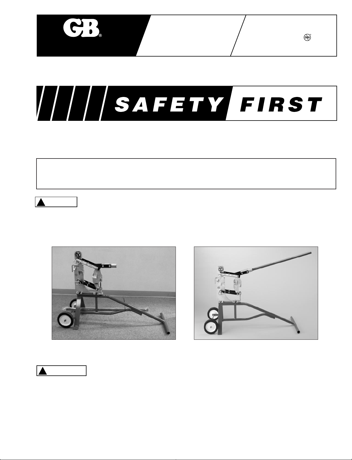
Upon initial receipt
Fully assembled
TO AVOID POOR QUALITY BENDS, BE SURE BRACKET TO FRAME MOUNTING HARDWARE IS
TIGHTENED SNUGLY TO PREVENT SIDE-TO-SIDE MOVEMENT. CHECK HARDWARE PERIODICALLY
OR IF EXCESS BRACKET MOVEMENT IS ENCOUNTERED.
1
Page 2
!
CAUTION
Initial Set-up Procedures
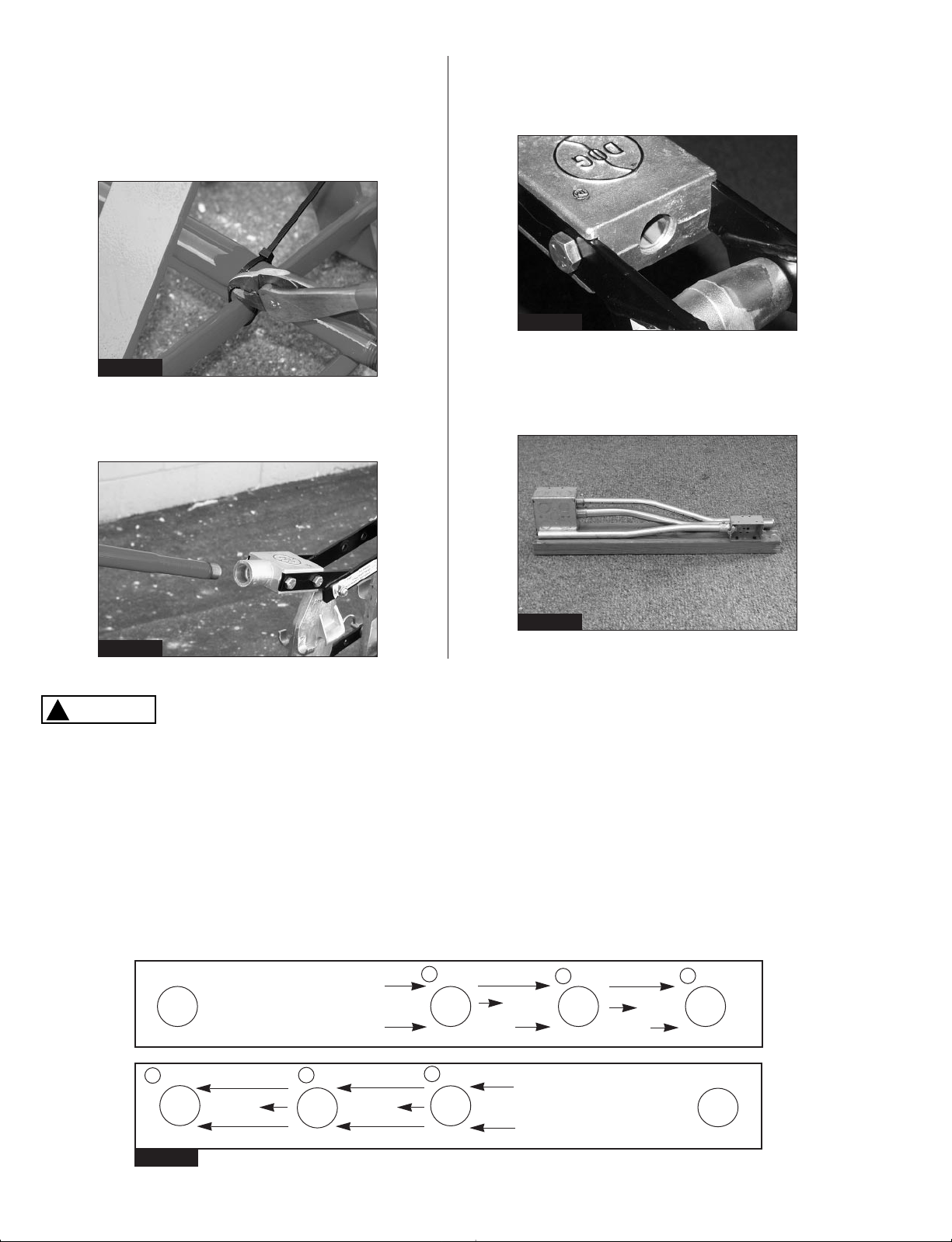
1. Remove all packing materials. Remove the
bender handle from the lower frame by cutting
the cable ties securing the handle to the frame.
See Figure 1.
The threads should pass all the way through and
be flush with the back side of the yoke.
See Figure 3.
Figure 3
Figure 1
3. Once the initial set-up is complete, the bender
will require specific steps to accomplish various
2. Install the bender handle by threading it
conduit bends. See Figure 4.
completely into the yoke.See figure 2.
Figure 4
Figure 2
DO NOT ATTEMPT TO BEND CONDUIT OTHER THAN 1⁄2" EMT (THINWALL), IMC AND RIGID OR 3⁄4"
EMT CONDUIT. USE OF ANY OTHER SIZES OR TYPES OF CONDUIT WILL DAMAGE THE BENDER
AND COULD CAUSE INJURIES.
Operating Procedures
1. Bending conduit is accomplished using jaws on the frame to stabilize the conduit. The jaws are
designed to accomidate specific types and sizes of conduit.
2. Determine the size and type of conduit, and the offset height required. Review the bracket decals to
locate the correct side of the frame to use. See Figure 5.
Patent pending
3
1
+
⁄2"
Figure 5
1
⁄2" EMT
Offset Height Range
Add to Height for Springback
Pin Position
2
0"-21⁄2"
3
+
⁄8"
0"-11⁄2"
0"-3⁄4"
1
1
+
⁄8"
1
0"-3⁄4"
1
+
⁄4"
2
0"-2"
Pin Position
Offset Height Range
Add to Height for Springback
3
+
0"-3"
⁄16"
3
⁄4" EMT
3
5
+
⁄16"
Patent pending
2
Page 3

3. Each bracket decal contains three vital pieces
of information.
a. Pin Position: Three locations to insert
retaining pin, which will produce different
heights of offset bends.
b.Offset Height Range: The range of offset
height that this pin hole position will
3
produce. (ie.0-
⁄4", 0-2" and 0-3")
c. Add to Height for Springback:The fraction
with a plus sign indicates the amount to
add to the offset height to correct for
conduit springback.
4. Select the correct hole location on the bracket,
pull the retaining pin and move the bracket until
the selected hole lines up with the frame hole.
Insert the retaining pin. See Figure 6.
Example: Offset height required = 2 inches
Conduit is
1
⁄2" EMT.
Hole Location is #2
Fraction added is +
1
⁄8", therefore
2"+1⁄8" = 21⁄8"
1
2
⁄8" is stop screw measurement for
step 6.
Figure 8
7. Lower the bender handle and complete the
bend by pushing down until the handle stops
moving. See Figure 9A. Raise the handle and
remove the conduit.See Figure 9B.
Figure 6
5. Raise the bender handle and insert the conduit
into the correct size bending jaws (check bend
bracket decals).See Figure 7. Be sure the
conduit extends a minimum of 2" beyond the jaw.
Figure 7
6. Set the bend stop screw adjustment by turning
the screw until the distance between the bottom
of hex head and the bottom of the frame is the
offset height plus the fractional number on the
decal. See Figure 8.
Figure 9A
Figure 9B
3
Page 4

Gardner
Bender
A unit of Tools and Supplies
Forming a Saddle Bend
1. Repeat steps listed in Operating Procedures
and complete the first offset bend.
2. Do not remove conduit.Keep all adjustments
and settings the same. Raise the bender handle
until the conduit can be slid forward.Slide the
conduit forward until the end of the first offset
bend is positioned past the second jaw. See
Figure 10. Level the conduit and hold it steady.
Figure 10
3. Push the handle down to complete the second
offset bend. See Figure 11. Raise the handle
and remove the conduit.
Conduit Reamer
1.The conduit reaming tool has a blade for the
inside and outside surface of the conduit.
Complies with article 348-11 of NEC.
2. Press the open end of the conduit against the
reamer blade.Hold the conduit fir mly and rotate
it 2 or 3 times to remove burrs and shar p edges.
See Figure 12.
Figure 12
Repeat Bending Feature
1. An adjustable length indicator is located on the
front edge of the bend frame.The indicator has
a maximum travel of 4 inches. See Figure 13.
2. Position the conduit into the bending jaws.
Loosen the thumb screw and move the indicator
until it contacts the end of the conduit.Tighten
the thumb screw. See Figure 13.
Adjustable
Length
Indicator
Figure 11
Figure 13
REPAIR AND SERVICE INSTRUCTIONS: For repair service and parts contact your nearest Gardner Bender Service Center. The GB
Service Center will provide complete and prompt service on all Gardner Bender products.
PARTS AND SERVICE: For quality workmanship and
genuine Gardner Bender parts, select an Authorized
Gardner Bender Service Center for your repair needs.
Only repairs performed by an Authorized Service
Center displaying the official Gardner Bender
Authorized sign are backed with full factory warranty.
Contact Gardner Bender (414)352-4160 for the name
of the nearest GB Authorized Service Center.
WARRANTY:Gardner Bender warrants its product
against defects in workmanship and materials for 1
year from date of delivery to user.Chain is not
warranted.Warranty does not cover ordinary wear
and tear, abuse, misuse, overloading, altered
products or use of improper fluid.
WARRANTY RETURN PROCEDURE:When question
of warranty claim arises, send the unit to the nearest
Gardner Bender Authorized Service Center for
inspection, transportation prepaid. Fur nish evidence of
purchase date. If the claim comes under the terms of
our warranty the Authorized Service Center will REPAIR
OR REPLACE PARTS AFFECTED and return the unit
prepaid.
6101 N. Baker Road, Milwaukee, WI 53209 • Phone:(414)352-4160 • FAX (414)352-2377
ZRPS-0135 4/99
 Loading...