

GB BGB300 Owner's Manual
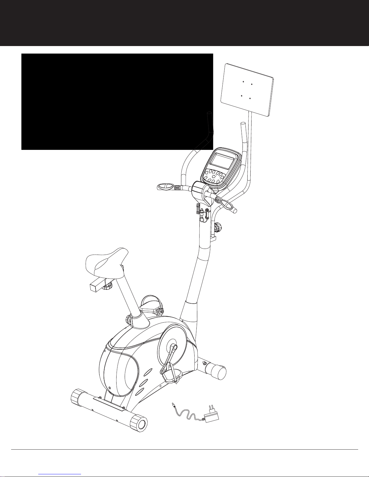
BGB300 GAME RIDER
* This item is for consumer use only and it is not meant for commercial use.
OWNER’S MANUAL

This page intentionally left blank
General Information
Safety
Before you undertake any exercise program,
please be sure to consult with your doctor.
Frequent strenuous exercise should be
approved by your doctor and proper use
of your product is essential. Please read
this manual carefully before commencing
the assembly of your product or starting to
exercise.
• Please keep all children away from this item
when in use. Do not allow children to climb or
play on them when they are not in use.
• Supervise teenagers while they use this unit.
• For your own safety, always ensure that there
is at least 3 feet of free space in all directions
around your product while you are exercising.
• Regularly check to see that all nuts, bolts and
fittings are securely tightened. Periodically
check all moving parts for obvious signs of
wear or damage.
• Clean only with a damp cloth, do not use
solvent cleaners. If you are in any doubt, do
not use your product; contact CUSTOMER
SUPPORT.
• Before use, always ensure that your product
is positioned on a solid, flat surface. If
necessary, use a rubber mat underneath to
reduce the possibility of slipping.
Always wear appropriate clothing and
•
footwear such as training shoes when
exercising. Do not wear loose clothing that
could become caught in moving parts during
exercise.
• Do not use this unit if it is not functioning
properly or if it is not fully assembled.
• Do not use this unit for commercial purposes.
• Before use, you must read and understand all
instructions & warnings stated in this Owner’s
Manual as well as posted on the equipment.
• It is the facility owner’s responsibility to properly
instruct users on the proper operation of the
equipment and to warn them of the potential
hazards.
• If at any time during exercise you feel faint, dizzy
or experience pain, stop and consult your
physician.
Assembling Tools
- Ruler with both metric and English measurements
- 2 x Adjustable Wrenches
- 1 x Philips (”Crosshead”) Screw Driver
Weight Limit
Your product is suitable for users weighing:
250 pounds or less.
Storage and Use
Your product is intended for use in clean
dry conditions. You should avoid storage in
excessively cold or damp places as this may
lead to corrosion and other related problems.
Warranty
Body Flex Sports warrants your product for
a period of 1 year for the frame and 90 days
on all parts if the item is used for the intended
purpose, properly maintained and not used
commercially. Any alterations or incorrect
assembly of the product will void this warranty.
Proof of purchase must be presented for any
warranty validation (no exceptions). This
warranty applies to the original purchaser only
and is not transferable.
This warranty does not cover abuse or defects
caused during use, storage or assembly.
During the warranty period, Body Flex Sports
reserves the right to:
a). provide replacement parts to the
purchaser in an effort to repair the item.
b). repair the product returned to our
warehouse (at the purchaser’s cost).
c). replace the product if neither of the two
previously mentioned actions effect repair.
This warranty does not cover normal wear and
tear on upholstery.
Questions
If you have any questions concerning the
assembly of your item or if any parts are
missing, please DO NOT RETURN THE
ITEM TO THE STORE OR CONTACT THE
RETAILER. Our dedicated customer service
staff can help you with any questions you may
have regarding the assembly of this unit and
can also mail you replacement parts.
Customer Support
Customer Support is open 9:00 a.m. to 5:00
p.m. (Pacific Time) Monday through Friday.
Please contact us by any of the following
means.
Body Flex Sports, Inc.
21717 Ferrero Parkway, Walnut, CA 91789
Telephone: (888) 266 - 6789
Fax: (909) 598 - 6707
Email: info@bodyflexsports.com
BGB 300 Page 1
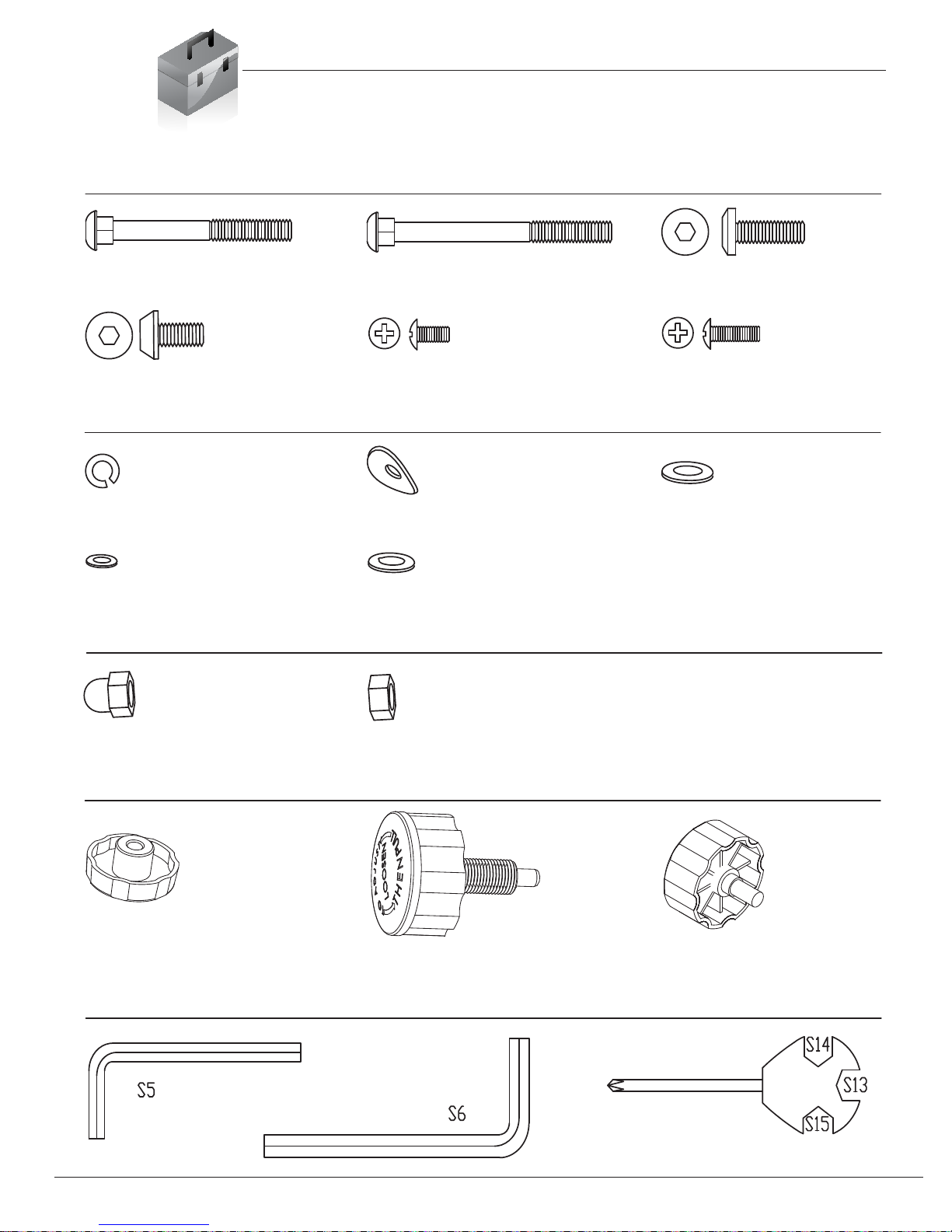
Bolt
Hardware List
The following hardware is used to assemble your unit. Please take a moment to familiarize yourself with these
items. Please note some of this hardware is already pre-assembled on the machine. Do not be alarmed if you
see parts on this page that are not included in your hardware packet
#13 Carriage Bolt (M8x73 mm)
[2 Pieces]
#23 Screw (M8x16 mm)
[4 Pieces]
Washer
#27 Spring Washer (M8)
[2 Pieces]
#30 Washer (M5)
[4 Pieces]
Nut
#14 Carriage Bolt (M8x90 mm)
[2 Pieces]
#25 Screw (M5x10 mm)
[4 Pieces]
#28 Arc Washer (M8)
[8 Pieces]
#32 Washer (M8, OD16)
[3 Pieces] Pre-assembled
#22 Screw (M8x25 mm)
[2 Pieces]
#26 Screw (M5x16 mm)
[3 Pieces]
#29 Washer (M10)
[1 Piece]
#15 Lock Nut (M8)
[4 Pieces]
Knob
#16 Knob (M10)
[1 Piece]
Tool
BGB 300
#33 Nut (M8)
[3 Pieces] Pre-assembled
#17 Spring Knob
(M16x27 mm) [1 Piece]
#18 Knob (M8x15 mm)
[1 Piece]
Page 2

Parts Listing
The following parts list describes all of the parts illustrated on the
exploded diagram on the following page. Please note, most of
these parts are already pre-assembled on your unit.
# Description # Description
01 Main Frame
02 Front Stabilizer
03 Rear Stabilizer
04 Center Post
05
Handle Bar
06 Monitor Support Bracket
07 Seat Post
08 Horizontal Seat Bar
09 Seat
10L Pedal (Left)
10R Pedal (Right)
11 Poster Support
12 Poster Board
13 Carriage Bolt (M8x73 mm)
14 Carriage Bolt (M8x90 mm)
15 Lock Nut (M8)
16 Knob (M10)
17 Spring Knob (M16x27 mm)
18 Knob (M8x15 mm)
19 Lock Pin
20 Screw (M5)
21 Screw (ST4)
22 Screw (M8x25 mm)
23 Screw (M8x16 mm)
24 Screw (ST3)
25 Screw (M5x10 mm)
26 Screw (M5x16 mm)
27 Spring Washer (M8)
28 Arc Washer (M8)
29 Washer (M10)
30 Washer (M5)
31 Washer (M6)
32 Washer (M8,OD16)
33
34
Nut (M8)
Center Post Cover
35
36
37
38
39
40 Square End Cap (38 mm)
41 Square End Cap (20 mm)
42 Round End Cap
43 Monitor
43a Left Handle Pulse Wire (Upper)
43b Right Handle Pulse Wire (Upper)
43c Main Sensor Wire (Upper)
43d Handle Sensor Wire (Upper)
44 Main Sensor Wire (Lower)
45a/b Main Sensor Wire (Middle)
46 Handle Sensor Wire (Lower)
47 Left Handle Pulse Wire (Lower)
48 Right Handle Pulse Wire (Lower)
49L Left Handle Bar Button
49R Right Handle Bar Button
50a AC Adapter for Wireless Box (DC 6V, 1000mA)
50b AC Adapter for Bike (DC 8V,1000mA)
51 Wireless Box
52a AV Cable (Upper)
52b Audio Cable (Lower)-White
52c Video Cable (Lower)-Yellow
53a USB Cable (Upper)
53b USB Cable (Lower)
54 Pulse Sensor
55 Resistance Band
56L Crank (Left)
56R Crank (Right)
57
58
59
60
Shroud
End Cap for Front Stabilizer
End Cap for Rear Stabilizer
Bushing
Rubber Ring (φ50 mm)
Handle Bar Cover (Lower)
Handle Bar Cover (Upper)
Rubber Ring (φ60 mm)
U Bracket
Page 3BGB 300
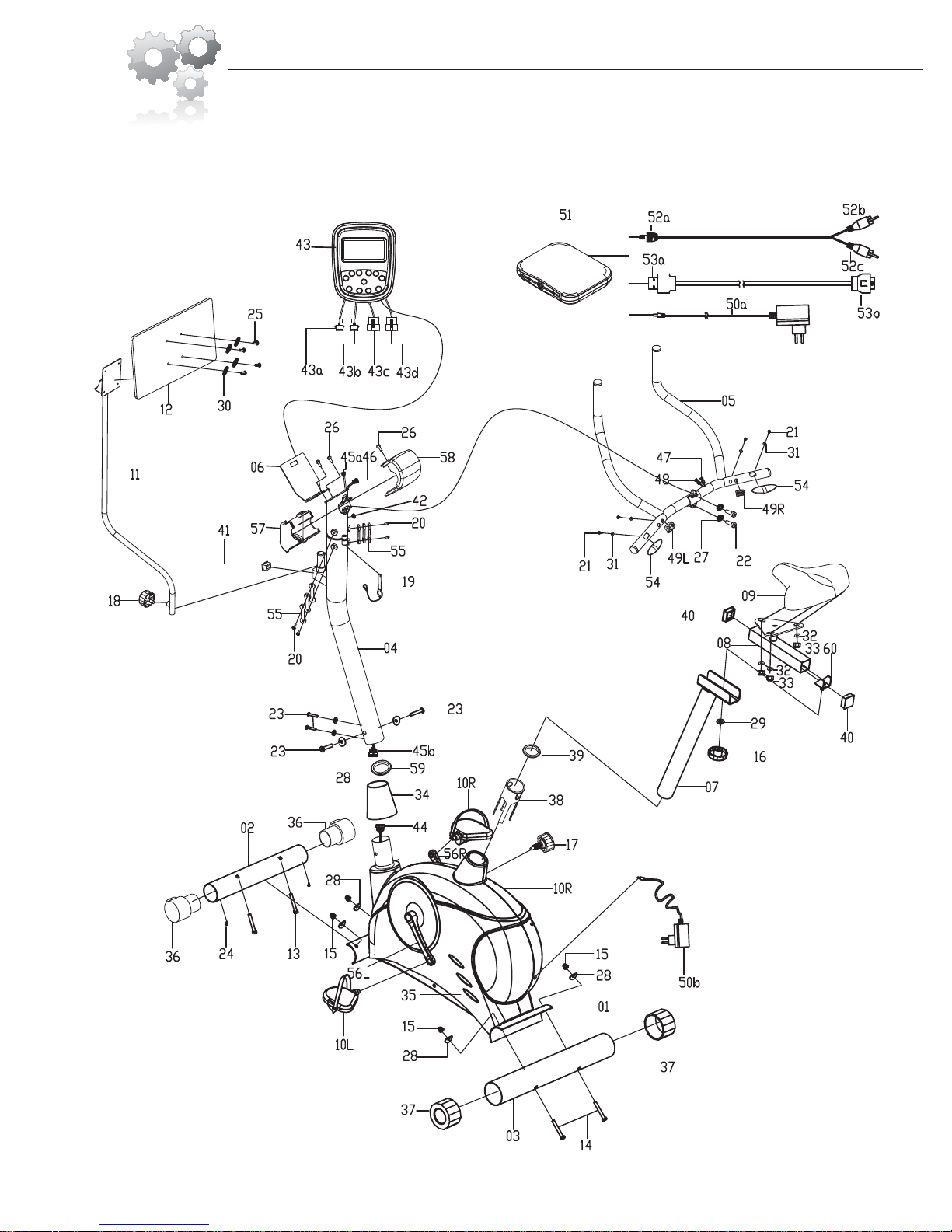
Exploded Diagram
The following diagram is provided to help you familiarize yourself with the parts and
hardware that will be used during the assembly process. Please note that not all of the
parts and hardware you see here will be used while you are assembling the machine
because some of these items are already pre-installed. Please continue to the next
page to begin the assembly process and use this page only as a reference guide for
parts and hardware.
BGB 300
Page 4
Assembly Instructions
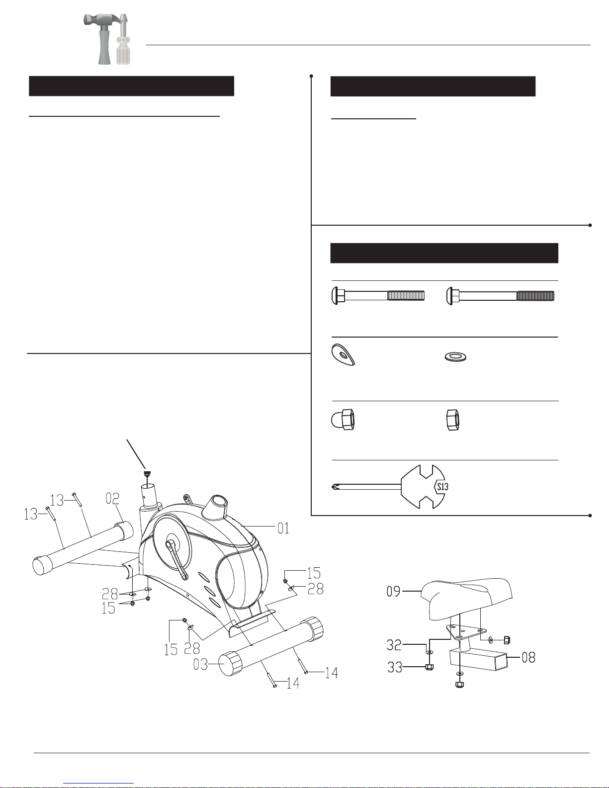
A s s e m b l y S t e p 1
Front & Rear Stabilizer Assembly
With the help of an assistant, attach the Front Stabilizer
(#02) to bracket at the front of Main Frame (#01). Insert two
Carriage Bolts (#13) through the Front Stabilizer (#02)
followed by the front Main Frame (#01). Secure them
together using two Arc Washers (#28) and two Lock Nuts
(#15). Now attach the Rear Stabilizer (#03) to the bracket
at rear of Main Frame (#01). Insert two Carriage Bolts (#14)
through the Rear Stabilizer (#03) followed by the rear
Main Frame (#01). Secure them together using two Arc
Washers (#28) and two Lock Nuts (#15).
NOTE: The Front Stabilizer (#02) has wheels on the end
caps that spin for ease of relocating and transporting the unit.
The Rear Stabilizer (#03) has height adjustable end caps
for leveling of the unit .
Make sure the wire is hanging out before
proceeding to the next step. If it has fallen
inside the tube, use a bent wire to “fish” them out.
A s s e m b l y S t e p 2
Seat Assembly
Remove the three Washers (#32) and three Nuts (#33)
that are pre-installed on the Seat (#09) as illustrated and
set them aside. Align the holes of the Seat (#09) to the
Horizontal Seat Bar (#08) as shown in the diagram.
Next, secure them together using three Washers (#32)
and three Nuts (#33) that were previously removed.
Hardware & Tool Required
Bolt
#13 Carriage Bolt (M8x73 mm)
[2 Pieces]
Washer
#28 Arc Washer (M8)
[4 Pieces]
Nut
#15 Lock Nut (M8)
[4 Pieces]
Tool
#14 Carriage Bolt (M8x90 mm)
[2 Pieces]
#32 Washer (M8, OD16)
[3 Pieces]
#33 Nut (M8)
[3 Pieces]
BGB 300 Page 5
Assembly Instructions
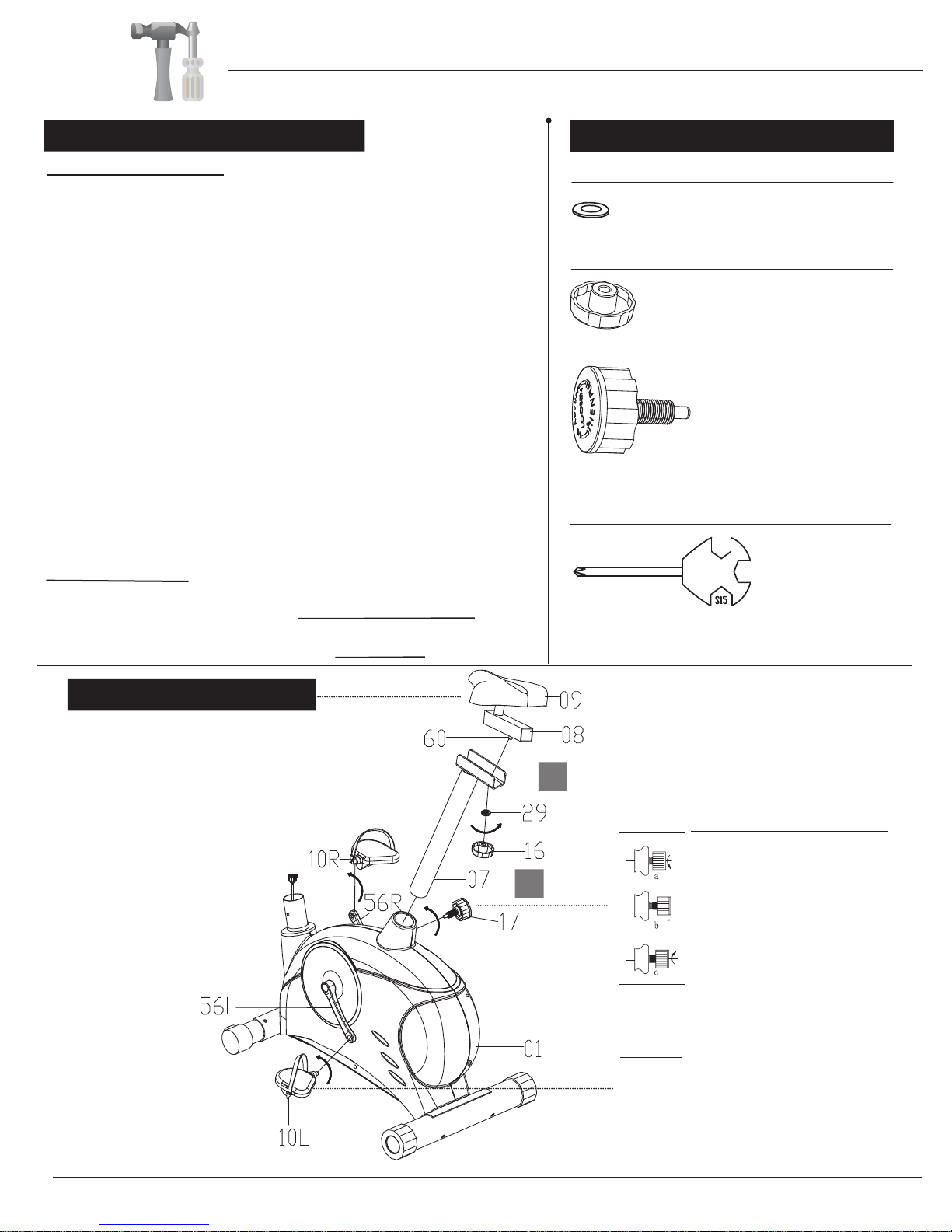
A s s e m b l y S t e p 3
Seat Post Assembly
A.) Attach the Horizontal Seat Bar (#08) onto the Seat Post (#07) by
inserting the bolt (on the bottom of the
through the Seat Post (#07), secure them using a Washer (#29)
and a Knob (#16). This knob can be loosened to adjust the distance
of the seat from the handle bars. Make sure to tighten the knob after
making any adjustment,
B.) If the Seat Post (#07) is not already pre-assembled, please insert
the Seat Post (#07) into the mouth of the post that is protruding
from the Main Frame (#01). Please ensure that the hole on the Seat
Post (#07) is facing the right so it can be aligned with the corresponding
hole on the Main Frame (#01). Screw in the Spring Knob (#17)
through the Main Frame (#01) post and through any hole located on
the Seat Post (#07). Please refer to illustration. To use the
safety-featured Spring Knob (#17), use one hand to hold the Seat
(#09) to prevent sudden slipping and the other hand to loosen the
knob by turning it counter-clockwise three times as you pull it outward.
Adjust the seat height to your liking and then pop the knob back in.
Then, tighten the knob by turning it clockwise. Please do not
over-tighten.
but do not over tighten the knob.
Pedal Assembly
Screw the
bolt head on the Pedal [Left](#10L) COUNTER-CLOCKWISE.
Screw the Pedal [Right](#10R) to the Crank [Right] (#56R) by turning
the bolt head on the Pedal [Right](#10R) CLOCKWISE.
Pedal [Left](#10L) to the Crank [Left] (#56L) by turning
Horizontal Seat Bar (#08))
the
Hardware & Tool Required
Washer
#29 Washer (M10)
Knob
#16 Knob (M10)
#17 Spring Knob
Tool
[1 Piece]
[1 Piece]
(M16x27 mm)
[1 Piece]
W A R N I N G
Do not remove the Seat (#09) for any
reason after you have installed it.
Exercising on this unit without the Seat
(#09) can result in SERIOUS INJURY.
Ensure the seat is locked in place by
tightening the two knobs prior to use.
B
A
Spring Knob Operation
Turn knob counter-clockwise
three times.
Pull knob outward and adjust
seat simultaneously
Push knob back inward until
it clicks and then tighten it by
turning clockwise.
NOTE:
If labels designating the Left/Right Pedal
are not present, please check pedals
closely for embossed
These will be “L” / “R” letters that
raised on the pedal material.
“L”/ “R” letter marks.
are
BGB 300
Page 6
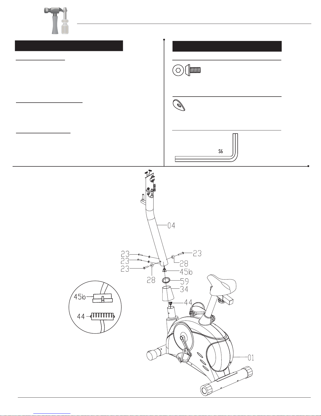
Assembly Instructions
A s s e m b l y S t e p 4
Wire Connection
Remove the Rubber Ring (#59) and Center Post Cover
(#34) from packaging and slide them
Post (#04) for now.
[Middle] (#45b) to the Main Sensor Wire [Lower] (#44)
Then, connect the Main Sensor Wire
Center Post Assembly
Slide the Center Post (#04) onto the Main Frame (#01)
and secure it using a total of four Arc Washers (#28) and
four Screws (#23).
Center Post Cover
Then, slide down the Center Post Cover (#34) and Rubber
Ring (#59)
snugly over the Main Frame (#01) . Please refer to positioning
of the
in the diagram below.
and twist/turn clockwise so it fits properly and
Center Post Cover (#34) and Rubber Ring (#59)
onto and up the
Center
.
Hardware & Tool Required
Bolt
#23 Screw (M8x16 mm)
Washer
#28 Arc Washer (M8)
Tool
[4 Pieces]
[4 Pieces]
BGB 300 Page 7
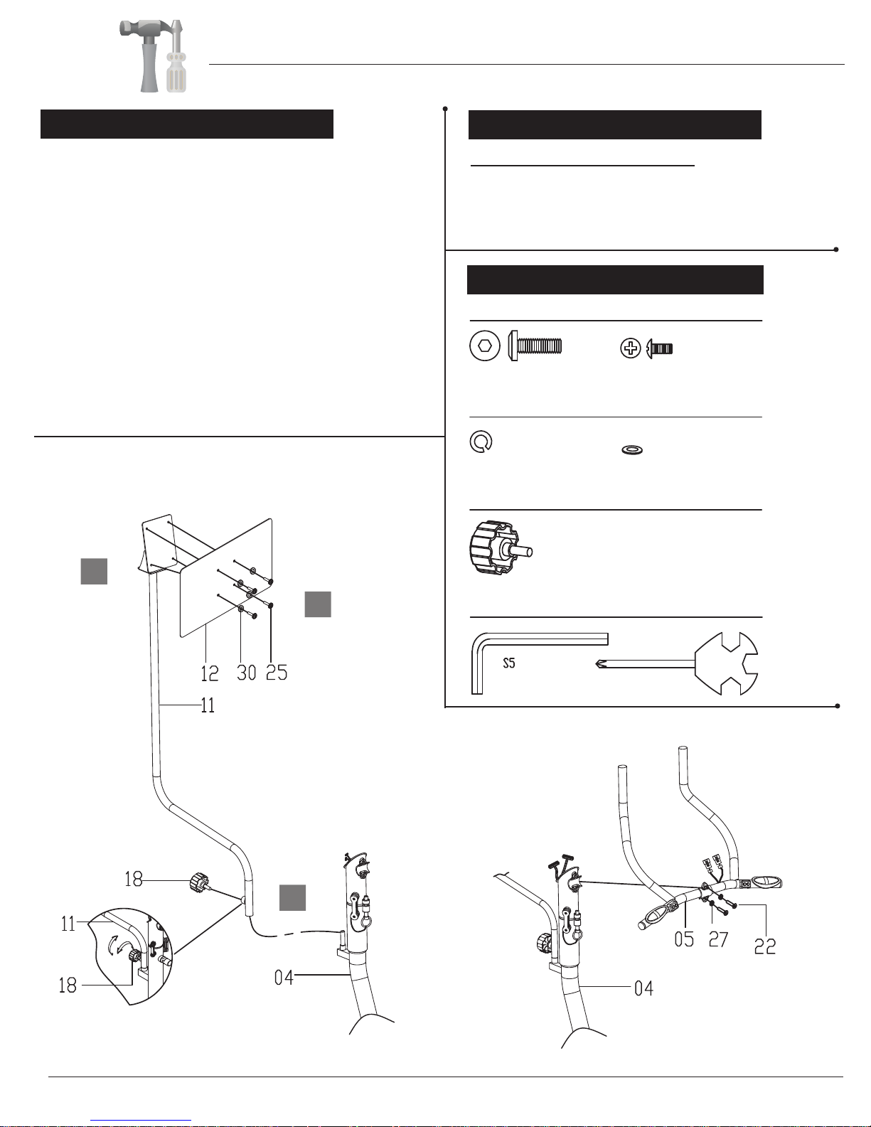
Assembly Instructions
A s s e m b l y S t e p 5
A.Place the Poster Support (#11) onto the corresponding
stem protruding from the Center Post (#04). Secure in
place using the Knob (#18) and tighten in place. You can
adjust the Poster Support (#11) location to your preference
by securing at the preferred angle.
B.Affix the Poster Board (#12) onto the plate of the Poster
Support (#11) using four Washers (#30) and four Screws
(#25).
C.The Poster Board (#12) and Poster Support (#11) are
intended to provide an easy-to-access guide to highlight
the key features and functions of the Game Rider. We
suggest placing the Poster Board (#12) at a 45 degree
angle to the user on either the right or left side.
A s s e m b l y S t e p 6
Pulse Handle Bar Assembly
Install the Handle Bar (#05) onto the inner side of the
Center Post (#04) using two Screws (#22) and two
Spring Washers (#27) as seen in diagram.
Hardware & Tool Required
Bolt
#22 Screw (M8x25 mm)
[2 Pieces]
Washer
#27 Spring Washer (M8)
[2 Pieces]
Knob
#25 Screw (M5x10 mm)
[4 Pieces]
#30 Washer (M5)
[4 Pieces]
C
A
B
#18 Knob (M8x15 mm)
[1 Piece]
Tool
BGB 300
Page 8
 Loading...