

Page 1
IMPORTANT: RECEIVING INSTRUCTIONS: Visually inspect all components for shipping damage. If any shipping
damage is found, notify carrier at once. Shipping damage is NOT covered by warranty. The carrier is responsible for
all repair or replacement costs resulting from damage in shipment.
Gardner
Bender
Instruction
Sheet
BE400 Eegor™
Bending Table
IMPORTANT USER SAFETY AND PROTECTION: In setting up systems to fit your operations, care must be taken to
select the proper components and design to insure appropriate integration with your operations and existing
equipment and that all safety measures have been taken to avoid the risk of personal injury and property damage
from your application or system.
Preliminary Procedure:
Read all instructions carefully and completely before
attempting to mount a hydraulic bender on this table
and/or operate this table.
Hydraulic Bender Operation:
Read all Eegor™ hydraulic bender instructions
before attempting to assemble or operate your
hydraulic bender.
Use Standard Precautions with Hydraulic
Hoses and Couplings:
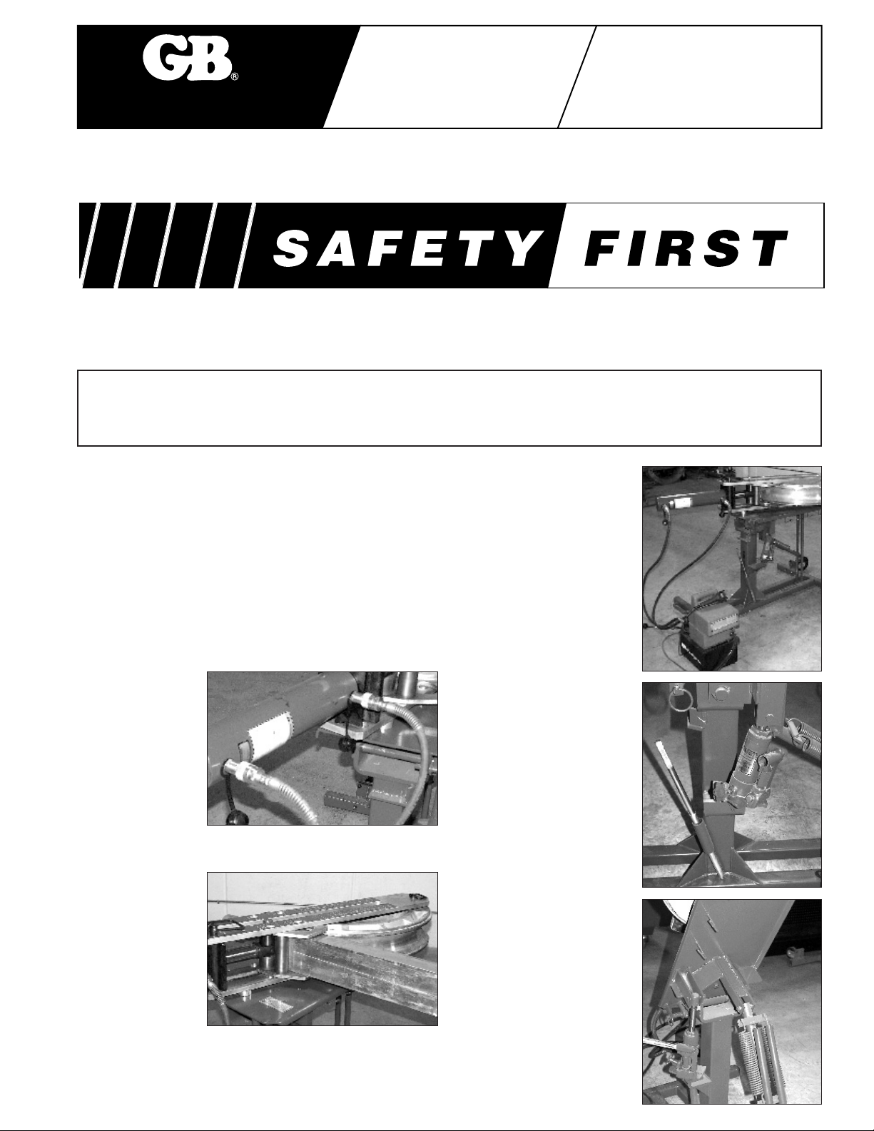
Avoid developing
sharp bends in, or
pinching, hoses.
Always provide
sufficient
clearances for
hoses and
couplings to avoid
rubbing or contact
with sharp edges.
Falling objects:
Before rotating
table top, always
remove any loose
objects from the
table or bender.
Check for proper
assembly of table,
bender and conduit
to avoid possible
injury due to falling
objects.
Clearances:
Before tilting table top,
always check for and
provide sufficient
clearances for table,
bender, and conduit.
Hydraulic Jack
Handle:
When you are not operating
hydraulic jack, place handle
in storage clips provided.
Keep Clear of
Possible Pinch
Points:
Motion between table
components could severely
pinch or cut any objects
wedged between.
GB ELECTRICAL, INC. CANNOT BE HELD RESPONSIBLE FOR DAMAGE OR INJURY CAUSED BY UNSAFE
USE, MAINTENANCE OR APPLICATION OF ITS PRODUCTS. Please contact GB's technical service department
for assistance if you are in doubt as to the proper safety precautions essential to designing and setting up your
particular application.
Page 2
Description
The Eegor™ Bending Table is designed to provide
mounting for an Eegor™ Hydraulic Bender. The table
positions the bender off the floor for easy, precise
bending and operator comfort. Hydraulic rotation of
the table top allows the user to accurately check
bending, and to obtain precise bends with the least
amount of effort.
Bender Mounting
1. Turn the Eegor™ bottom load arm / cylinder assembly
upside down, as shown in Fig. 1. Remove the four (4)
flat head cap screws, freeing the two (2) rest pads and
stabilizer bar from the load arm.
2. Position table top in horizontal position as shown in
Fig. 2.
3. Line up the two (2) pads and stabilizer bar, removed in
Step 1, on the table top over the four (4) mounting
holes as shown in Fig. 3. Position the load arm
cylinder assembly on the two (2) pads and stabilizer
bar on the table top with the cylinder positioned as
shown in Fig. 3. Line up the four (4) tapped holes in the
load arm with the four (4) mounting holes in the table
top. Fasten the load arm to the table top with the four (4)
1
⁄2 - 13 UNC x 13⁄4 long hex head cap screws supplied
with the table. Insert the cap screws through the bottom
of the table top plate through the pads and into the
tapped holes of the load arm. (Torque the cap screws to
50 ft. lbs.)
Properly support the overhanging
cylinder until the load arm / cylinder
assembly is secured to the table top.
4. The bottom load arm / cylinder assembly is now
securely mounted on the table top. Consult the
Eegor™ Hydraulic Bender instruction sheet for
complete bender set up and operating instructions.
Always provide proper support for
bender components and conduit during
set up and removal operations.
Improper support could result in a
serious injury.
Side Support Stand
The side support stand is provided to aid in the set up
and removal of the larger sizes of conduit.The stand is
attached to the bender table at a single pivot point to
provide maximum required stability while maintaining a
flexible stand position.
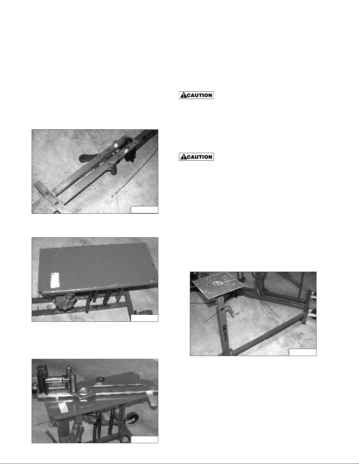
The correct assembly of the side support stand is shown
in Fig. 4.To attach the stand to the table, insert the pin
shown in Fig. 4 into the tube provided on the table base.
To adjust the height of the stand, loosen the L-screw
shown in Fig. 4. Move the top to the desired height and
retighten the L-screw to a firm hand tightness.
Before Bending
After the bending shoe (any size), top compression roller
assembly, top load arm, and bending shoe pivot pin
L-Screw
Figure 1
Figure 2
Figure 3
Figure 4
Page 3

have been installed per the Eegor™ Bender instruction
sheet, the safety hairpin (supplied with the bending
table) should be inserted in the bending shoe pivot pin
as shown in Fig.5.
Safety hairpin is required to prevent any
accidental dislodging of bender
components when table top is rotated to
its vertical position. Hairpin should be in
place at all times.
Table Operation
To change the table top position from horizontal (Fig. 6)
to vertical (Fig. 8), begin with all bender components
and conduit properly positioned and secured (with safety
hairpin inserted as shown in Fig. 5). Close the release
valve by turning it clockwise. Insert the jack handle
in jack, and operate the pump as indicated in Fig. 7.
Operate the pump until the table top is in a full vertical
position as shown in Fig. 8.
Do not attempt to install or remove any
conduit or bender components when
table top is in its vertical position.
2. To change the table top position from vertical (Fig. 8)
to horizontal (Fig. 6), open safety latch by pulling the
ring outward, as indicated in Fig. 9 and hold. Slowly
open jack release valve by turning counter-clockwise as
shown in Fig. 9A. The table top will automatically rotate
to its horizontal position. If the table top stops before
reaching its horizontal position, with the jack release
valve open, push lightly at the top of the table.
Pivot Pin
Figure 5
Figure 6
Figure 7
Figure 8
Figure 9
Figure 9A
Page 4

WARRANTY: GB ELECTRICAL, INC. warrants its
products against defects in workmanship and
materials for 1 year from date of delivery to user.
Chain is not warranted. Warranty does not cover
ordinary wear and tear, abuse, misuse, overloading,
altered products or use of improper fluid.
WARRANTY RETURN PROCEDURE: When question
of warranty claim arises, send the unit to the nearest
GB Authorized Service Center for inspection,
transportation prepaid. Furnish evidence of purchase
date. If the claim comes under the terms of our
warranty the Authorized Service Center will REPAIR
OR REPLACE PARTS AFFECTED and return the unit
prepaid.
PARTS AND SERVICE: For quality workmanship and
genuine GB ELECTRICAL parts, select an Authorized
GB Service Center for your repair needs. Only
repairs performed by an Authorized Service Center
displaying the official GB Authorized sign are backed
with full factory warranty. Contact GB Electrical
(414) 352-4160 for the name of the nearest GB
Authorized Service Center.
REPAIR AND SERVICE INSTRUCTIONS: For repair service and parts contact your nearest GB ELECTRICAL
Service Center.The Service Center will provide complete and prompt service on all GB ELECTRICAL products.
GB Electrical, Inc.
An Applied Power Company
6101 N. Baker Road, Milwaukee, WI 53209
Phone: (414) 352-4160 FAX (414) 352-2377
RPS-0036 Rev. A 03/07
The table top should always be lowered
from its vertical position at a slow,
controllable rate. A freely falling table
top will only shorten the life of your
bending table and bender components.
Open the jack release valve only enough
to provide a slow smooth return of your
table top and bender to their horizontal
position. Also, when changing the table
top position from horizontal to vertical or
vertical to horizontal, always check for and
provide proper clearances for table,
bender and conduit.
Maintenance of Table
1. To lubricate, apply #20 oil to all pivot points as
indicated in Fig. 10 at least once every month.
2. Retorque the four (4) mounting screws, indicated in
Fig. 10, monthly, to 50 ft. lbs. Visually inspect all
fasteners daily and retorque where necessary.
3. Periodically inspect table for worn and/or damaged
parts and replace where necessary.
Maintenance of Jack
Filling reservoir - with table top in horizontal position,
remove the filler plug as shown in Fig. 11. Add Enerpac
Hydraulic Oil until oil level is up to filler hole. Replace
filler plug. DO NOT use brake fluid, alcohol, glycerine,
and similar fluids. These fluids will damage packings and
corrode metallic parts.
Purging air - if the oil supply is low or if the table was on
its side, the pump may have become air bound. To purge
air from the system, proceed as follows:
1. Put table top in horizontal position.
2. Remove filler plug and check oil level (do not replace
filler plug).
3. Open release valve and operate pump several times.
4. Close the release valve, operate pump and check to
see that the table top raises. If the table top does not
raise, repeat steps 3 and 4.
5. If table top does not raise, lower it to its horizontal
position. Re-check the oil level and replace filler plug.
Figure 10
Figure 11
 Loading...